

Page 1

OPERATION AND PARTS MANUAL
Multiquip
Submersible Pump
Model ST-3050D
© COPYRIGHT 2002, MULTIQUIP INC.
Revision #1 (11/18/02)
MULTIQUIP INC.
18910 WILMINGTON AVENUE
CARSON, CALIFORNIA 90746
310 - 537-3700
800/421-1244 NATIONWIDE
FAX: 310 - 537-3927
PARTS DEPARTMENT:
800/427-1244
FAX: 800/672-7877
SERVICE DEPARTMENT:
800/478-1244
FAX: 310 - 537- 4259
Page 2

HERE'S HOW TO GET HELP
PLEASE HAVE THE MODEL AND SERIAL NUMBER
ON-HAND WHEN CALLING
PARTS DEPARTMENT
800/427-1244 or 310/537-3700
FAX: 800/672-7877 or 310/637-3284
SERVICE DEPARTMENT
800/478-1244 or 310/537-3700
FAX: 310 - 537-4259
WARRANTY DEPARTMENT
800/421-1244, EXT. 279 or 310/537-3700
FAX: 310 - 537-1173
MAIN
800/421-1244 or 310/537-3700
FAX: 310 - 537-3927
PAGE 2 — ST-3050D — PARTS & OPERATION MANUAL — REV. #1 (11/18/02)
Page 3
ST-3050D SUBMERSIBLE PUMP — TABLE OF CONTENTS
Here's How To Get Help ............................................2
Table Of Contents .....................................................3
Parts Ordering Procedures .......................................4
Safety Message Alert Symbols .................................5
Rules For safe Operation ..................................... 6-7
Specifications (Pump) ...............................................7
General Information .................................................. 9
ST-3050D Submersible
Pump
Components............................................................ 10
Application (Float Switches) ....................................11
Control Boxes.......................................................... 12
Control Box Installation (CB200)............................. 13
230/460 VAC Voltage Selection ...............................14
Pump Wiring Diagram .............................................15
Transformer Wiring Diagram (CB200) ....................16
Control Box Wiring Diagram (CB200) .....................17
Three-Phase Power Installation (CB200) ......... 18-19
Control Box Pre-Setup (CB200)........................ 20-21
Control Box Installation (MP102/104) .....................22
Control Box Wiring Diagram (MP102/104) ..............23
Operation .......................................................... 24-25
Maintenance ........................................................... 26
Pump Troubleshooting/Performance Curve ............27
Explanation Of Codes In Remarks Column ............28
Suggested Spare Parts ........................................... 29
Electric Submersible Pump Assembly .............. 30-33
Electric Motor Assembly.................................... 34-35
NOTE
Specification and
part number are
subject to change
without notice.
Terms and Condition of Sale
ST-3050D — PARTS & OPERATION MANUAL — REV. 0 (11/18/02) — PAGE 3
— Parts .....................36
Page 4

PARTS ORDERING PROCEDURES
■■
■ Dealer account number
■■
■■
■ Dealer name and address
■■
■■
■ Shipping address (if different than billing address)
■■
■■
■ Return fax number
■■
■■
■ Applicable model number
■■
■■
■ Quantity, part number and description of each part
■■
■■
■ Specify preferred method of shipment:
■■
UPS Ground
•
UPS Second Day or Third Day*
•
UPS Next Day*
•
Federal Express Priority One (please provide us with your Federal
•
Express account number)*
Airborne Express*
•
Truck or parcel post
•
*Normally shipped the same day the order is received, if prior to 2PM west coast time.
Earn Extra Discounts when
you order by FAX!
All parts orders which include complete part numbers
and are received by fax qualify for the following extra
discounts:
Number of
line items ordered Additional Discount
1-9 items 3%
10+ items** 5%
Get special freight allowances
when you order 10 or more
line items via FAX!**
■■
■
UPS Ground Service at no charge for freight
■■
■■
■
UPS Third Day Service at one-half of actual freight
■■
cost
No other allowances on freight shipped by any other carrier.
**Common nuts, bolts and washers (all items under $1.00 list price)
do not count towards the 10+ line items.
*DISCOUNTS ARE SUBJECT TO CHANGE*
Fax order discount and UPS special programs revised June 1, 1995
Extra Fax DiscountExtra Fax Discount
Extra Fax Discount
Extra Fax DiscountExtra Fax Discount
for Domestic USAfor Domestic USA
for Domestic USA
for Domestic USAfor Domestic USA
Dealers OnlyDealers Only
Dealers Only
Dealers OnlyDealers Only
Now! Direct TOLL-FREE access
to our Parts Department!
Toll-free nationwide:
800-421-1244
Toll-free FAX:
800/6-PARTS-7 • 800-672-7877
PAGE 4 — ST-3050D — PARTS & OPERATION MANUAL — REV. #1 (11/18/02)
Page 5
ST-3050D SUBMERSIBLE PUMP— SAFETY MESSAGE ALERT SYMBOLS
FOR YOUR SAFETY AND THE SAFETY OF OTHERS!
Safety precautions should be followed at all times when operating
this equipment. Failure to read and understand the Safety
Messages and Operating Instructions could result in injury to
yourself and others.
This Owner's Manual has been
developed to provide complete
instructions for the safe and efficient
NOTE
operation of the Multiquip
ST-3050D Submersible Pump.
Before using this pump, ensure
that the operating individual has
read and understands all
instructions in this manual.
Model
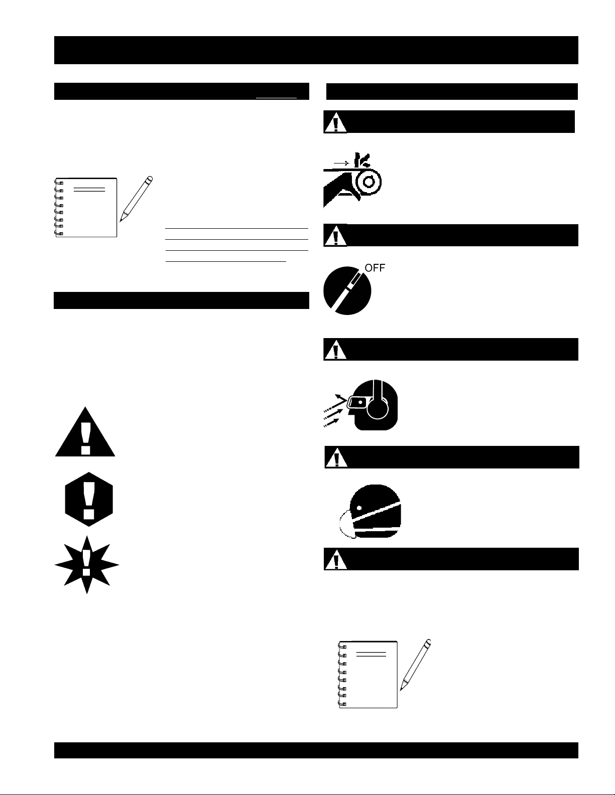
HAZARD SYMBOLS
SAFETY MESSAGE ALERT SYMBOLS
The three (3) Safety Messages shown below will inform you
about potential hazards that could injure you or others. The
Safety Messages specifically address the level of exposure to
the operator, and are preceded by one of three words: DANGER,
WARNING, or CAUTION.
Rotating Parts
NEVER operate equipment with covers,
or guards removed. Keep fingers, hands,
hair and clothing away from all moving
parts to prevent injury.
Accidental Starting
ALWAYS place the power source circuit
breaker or ON/OFF switch in the OFF
position, when the pump is not in use.
Sight and Hearing hazard
DANGER: You WILL be KILLED or
SERIOUSLY injured if you do not follow
directions.
WARNING: You CAN be KILLED or
SERIOUSLY injured if you do not follow
directions.
CAUTION: You CAN be injured if you
do not follow directions.
Potential hazards associated with the ST-3050D submersible
pump operation will be referenced with Hazard Symbols which
appear throughout this manual, and will be referenced in
conjunction with Safety Message Alert Symbols.
Other important messages are provided throughout this manual
to help prevent damage to your submersible pump, other property,
or the surrounding environment.
NOTE
ALWAYS wear approved eye and
hearing protection, if required.
Respiratory Hazard
ALWAYS wear approved respiratory
protection, if required.
Equipment Damage Messages
This submersible pump, other
property, or the surrounding
environment could be damaged if
you do not follow instructions.
ST-3050D — PARTS & OPERATION MANUAL — REV. 0 (11/18/02) — PAGE 5
Page 6
ST-3050D SUBMERSIBLE PUMP — RULES FOR SAFE OPERATION
■
CAUTION:
Failure to follow instructions in this manual may
lead to serious injury or even death! This
equipment is to be operated by trained and
qualified personnel only! This equipment is for
industrial use only.
The following safety guidelines should always be used when
operating the ST-3050D Submersible Pump:
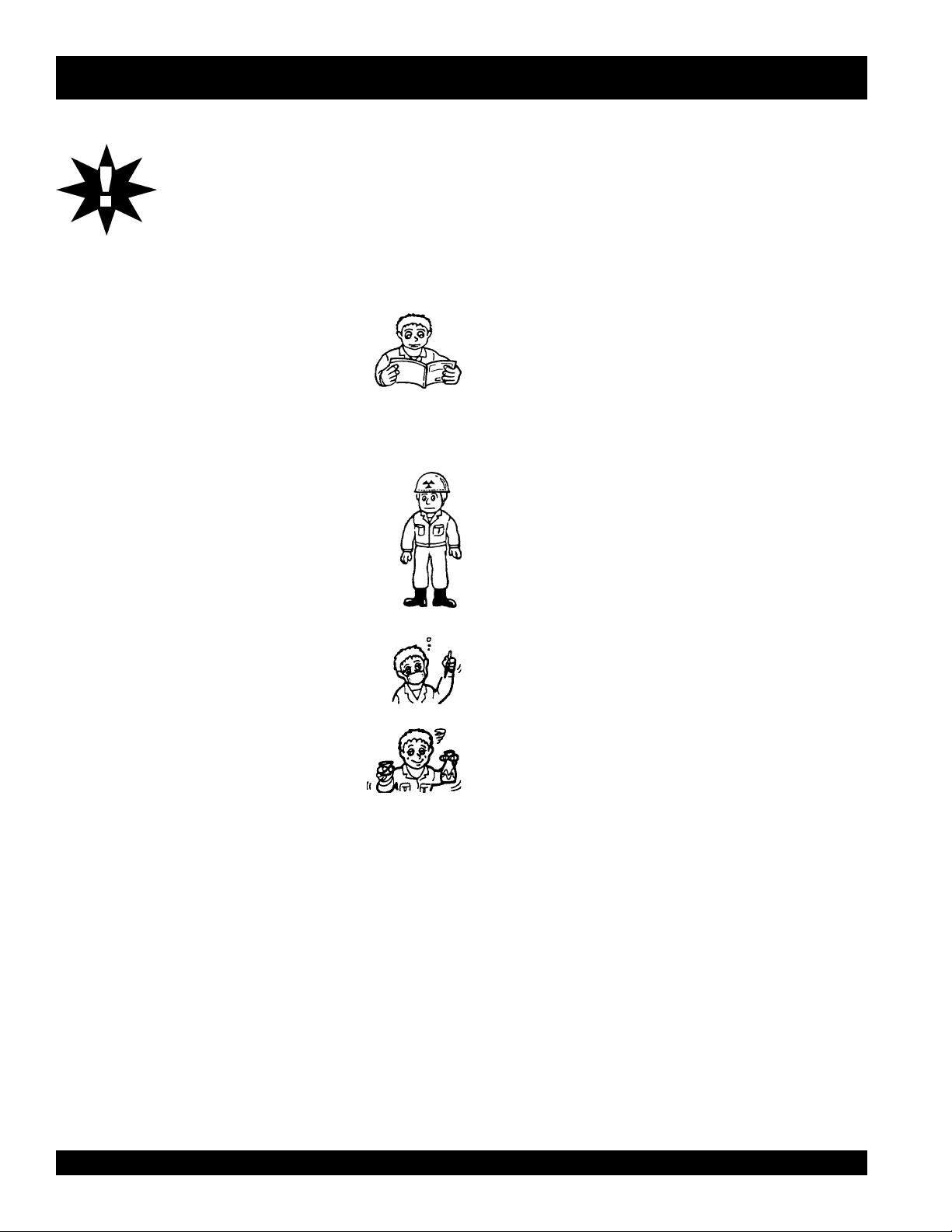
GENERAL SAFETY
■
DO NOT operate or service this equipment
before reading this entire manual.
■
This equipment should not be operated by persons under 18
years of age.
■
NEVER operate this equipment without proper
protective clothing, shatterproof glasses, steel-toed
boots and other protective devices required by the
job.
ALWAYS make sure submersible pump is grounded.
■
NEVER use gas piping as an electrical ground.
■
DO NOT place hands or fingers inside pump when pump is
running.
■
ALWAYS make certain that the voltage supplied to the pump
is correct. Always read the pump's nameplate to determine
what the power requirements are (230 or 460 VAC 3 phase).
■
DO NOT restrict the flow of the discharge hose as it may
cause overheating.
■
Be careful of discharge whipping under pressure.
■
Make sure pump installation is accordance with national
and local electrical codes.
■
ALWAYS have a qualified electrician perform the pump
wiring installation.
■
ALWAYS mount the control box in a vertical position
protected from the elements.
■
NEVER handle pump's AC power cord with
■
NEVER let an extension cord or plug connection
■
NEVER
to a power source.
stand in water
while AC power cord is connected
wet hands
.
lay in wate
r.
■
■
NEVER operate this equipment when not feeling
well due to fatigue, illness or taking medicine.
■
NEVER operate this equipment under the
influence or drugs or alcohol.
■
NEVER use accessories or attachments, which are not
recommended by Multiquip for this equipment. Damage to the
equipment and/or injury to user may result.
■
Manufacture does not assume responsibility for any accident
due to equipment modifications.
■
Whenever necessary, replace nameplate, operation and safety
decals when they become difficult read.
■
ALWAYS check the machine for loosened threads or bolts
before starting.
■
NEVER operate the submersible pump in an explosive
atmosphere or near combustible materials. An explosion or fire
could result causing severe
bodily harm or even death.
■
■
■
■
■
■
■
■
■
NEVER use a pump with a defective, frayed power cord.
Check the power cord on the pump for cuts in the insulation.
NEVER use a extension cord that is frayed or damaged
where the insulation has been cut.
ALWAYS make certain that proper extension cord has been
selected for the job See Table 3.
NEVER attempt to use the power cord as a lifting or lowering
device for the submersible pump.
When raising or lowering of the submersible pump is
required, always attach an adequate rope or lifting device
to the correct lifting point (handle) on the pump.
ALWAYS place the pump in an up-right position on a
platform before using. The platform will prevent the pump
from burrowing itself on soft sand or mud.
NEVER operate pump on its side.
DO NOT allow the pump to freeze in water.
NEVER leave an open pump chamber unattended.
The electrical voltage required to operate the pump can
cause severe injury or even death through physical contact
with live circuits.
from the pump before performing maintenance on the pump.
ALWAYS
disconnect the electrical power
PAGE 6 — ST-3050D — PARTS & OPERATION MANUAL — REV. #1 (11/18/02)
Page 7

ST-3050D SUBMERSIBLE PUMP — RULES FOR SAFE OPERATION
■
ALWAYS make sure that electrical circuits are properly
grounded
per the
National Electrical Code
(NEC) and
local codes before operating pump. Severe injury or death by
electrocution can result from operating an ungrounded pump.
■
NEVER use this pump to remove water from a swimming pool
when people are in the water.
■
ALWAYS be sure the operator is familiar with proper safety
precautions and operations techniques before using
submersible pump.
■
ALWAYS check pump oil level only when pump is cool.
Expansion due to heat may cause hot! oil to spray from the oil
plug when the oil plug is removed.
■
DO NOT attempt to thaw-out a frozen pump by using a torch
or other source of flame. Application of heat in this manner
may heat the oil in the seal cavity above the critical point,
causing pump damage.
■
DO NOT pump water greater than 104 degrees Fahrenheit.
Also DO NOT pump liquids containing acid or alkali.
■
ALWAYS check the dual voltage connection inside the pump
for proper voltage setting.
■
ALWAYS check strainer before pumping. Make sure strainer
is not clogged. Remove any large objects, dirt or debris from
the strainer to prevent clogging.
■
ALWAYS use a large basket strainer when pumping water
that contain large debris.
. Emergencies
■
■
■
ALWAYS know the location of the nearest
ALWAYS know the location of the nearest and
In emergencies
nearest phone or
always
know the location of the
keep a phone on the job site
fire extinguisher
first aid kit
.
Also know the phone numbers of the nearest
ambulance, doctor
and
fire department
. This
information will be invaluable in the case of an
emergency.
.
.
■
ALWAYS flush pump (clean) after use when pumping water
concentrated with heavy debris. It is very important to always
flush the pump before turning it off to prevent clogging.
■
ALWAYS store equipment properly when it is not being used.
Equipment should be stored in a clean, dry location out of the
reach of children.
■
ALWAYS read, understand, and follow procedures in
Operator’s Manual before attempting to operate equipment.
Maintenance Safety
■
NEVER lubricate components or attempt service on a running
machine.
■
ALWAYS allow the machine a proper amount of time to cool
before servicing.
■
Keep the machinery in proper running condition.
■
Fix damage to the machine immediately and always replace
broken parts.
ST-3050D — PARTS & OPERATION MANUAL — REV. 0 (11/18/02) — PAGE 7
Page 8

ST-3050D SUBMERSIBLE PUMP — SPECIFICATIONS
)pmuP(snoitacificepS.1elbaT
ledoMD0503-TS
epyTpmuPhsarTelbisrembuS
eziSegrahcsiD&noitcuS).mm67(.ni00.3
yticapaCgnipmuPmumixaM
retemaiDsdiloS.xaM).mm15(.ni00.2
tfiL.xaM)sretem26.7(.tf52
daeH.xaM)sretem00.62(.tf68
rewoP)wK57.3(PH5
esahPegatloV
pmuP
spmAgnitratS
spmAgninnuR
deriuqeRxoBlortnoCseY
noitcetorPdaolrevOlamrehTseY
noitatoResiwkcolC-retnuoC
yticapaClaeSliOlacinahceM)sretiL81.(.cc081
ecnaraelCrellepmI
etunim/snollag072
)etunim/sretil220,1(
3064/032
ø
CAV032@77
CAV064@93
CAV032@2.41
CAV064@1.7
1
2
.ni520.-210.
).mm536.-403.(
)deepS(MPR03±055,3
htgneLelbaCrewoP)sreteM26.7(.TF52
snoisnemiD
)retemaiDXthgieH(
thgieWteNyrD ).gK45(.sbl021
.ni8.62x2.01
).mc86X9.52(
1. Motor Rotation – Upon start-up, the pump "kicks" in the opposite direction of motor rotation. The correct rotation is counter-
clockwise (CCW) as viewed from the impeller end of the pump. Rotation direction for 3-phase pumps is changed by reversing
two of the power leads.
2. Mechanical Oil Seal – Use a good grade 10 weight non-detergent hydraulic oil (i.e. Shell Turbo 32 or equivalent). Fill oil cavity
75% to 85% full (allow air space for expansion).
PAGE 8 — ST-3050D — PARTS & OPERATION MANUAL — REV. #1 (11/18/02)
Page 9

ST-3050D SUBMERSIBLE PUMP — GENERAL INFORMATION
Introduction
The Multiquip Model ST-3050D submersible pump is designed
to pump water and is used for the draining (de-watering) of
swimming pools, well casings construction sites, cofferdams,
manholes, transformer vaults and excavations.
A vortex type impeller is attached to the output shaft of a 5.0 HP
electric motor which provides adequate power for general
purpose pumping. This submersible pump is supplied complete
with an electric power cable, and a discharge port located at the
top of the pump which accepts a 3-inch hose.
This pump is ideal for portability because of its light weight and
carrying handle. For reliability and long life, a mechanical seal
provides shaft sealing, with an oil chamber separating the pump
section from the motor.
The pump when in use, should be installed as free standing
(upright position) on its strainer base. A 3-inch discharge hose
(not supplied) should be connected to the discharge port located
on top of the pump. The discharge hose should be adequately
supported to avoid stress on the pump.
For maximum water flow, the discharge hose should be kept as
short as possible, and with minimum elevation above the pump.
Remember as the length and/or height of the discharge hose is
increased, the flow of water will be reduced. Also any reduction
in the hose size, and any fittings such as valves or outlet nozzles,
will restrict the water flow.
To avoid back-siphonage when the pump is switched off, ensure
that the end of the discharge hose is installed above the water
level at the final discharge point.
This pump must always be positioned on a platform in an upright
position. NEVER operate the pump by a suspended rope. To
prevent large solids from entering the pump, install a wire mesh
screen or similar barrier around the pump.
If the pump was used to pump water containing mud, silt, use
clean water to flush out the pump after each use.
DO NOT allow the pump to run dry, as this will damage the
pump. During maintenance, dry running is permissible but only
for a few seconds.
NEVER lift the pump by its electrical power cord. ALWAYS lift
the pump by its carrying handle or attached a rope to carrying
handle.
A pump fully submerged pump in liquid will not freeze, unless
the liquid freezes. DO NOT allow a partially submerged pump to
freeze. The expansion of water freezing in the volute may crack
the pump, causing expensive repairs. If there is any danger of
the pump being subjected to freezing temperatures, Lift the pump
from water and allow it to drain thoroughly.
If the pump jams or the pump rotor locks for any reason,
disconnect the pump from the power source immediately.
Allowing the pump motor to cycle ON and OFF under an overload
condition can burn out the motor.
When replacement of nuts and bolts is required, use only
recommended parts as referenced in the parts section of this
manual. This pump uses
measurement threads.
metric
threads. DO NOT use english
When the pump is switched off, the water remaining in the hose
will run back through the pump. This can be avoided by placing
a non-return valve in the hose nearest the pump.
NEVER use this submersible pump to pump flammable liquids
or operate in a explosive or flammable environment.
Avoid using this pump in conditions where mud, grit, silt or other
debris are present. These conditions could cause blockage and
cause excessive pump wear.
DO NOT install the pump directly into an area where there is a
heavy build-up of mud, grit, silt or debris. If this condition is present,
install the pump on a platform before operating.
ST-3050D — PARTS & OPERATION MANUAL — REV. 0 (11/18/02) — PAGE 9
Page 10
ST-3050D SUBMERSIBLE PUMP — COMPONENTS
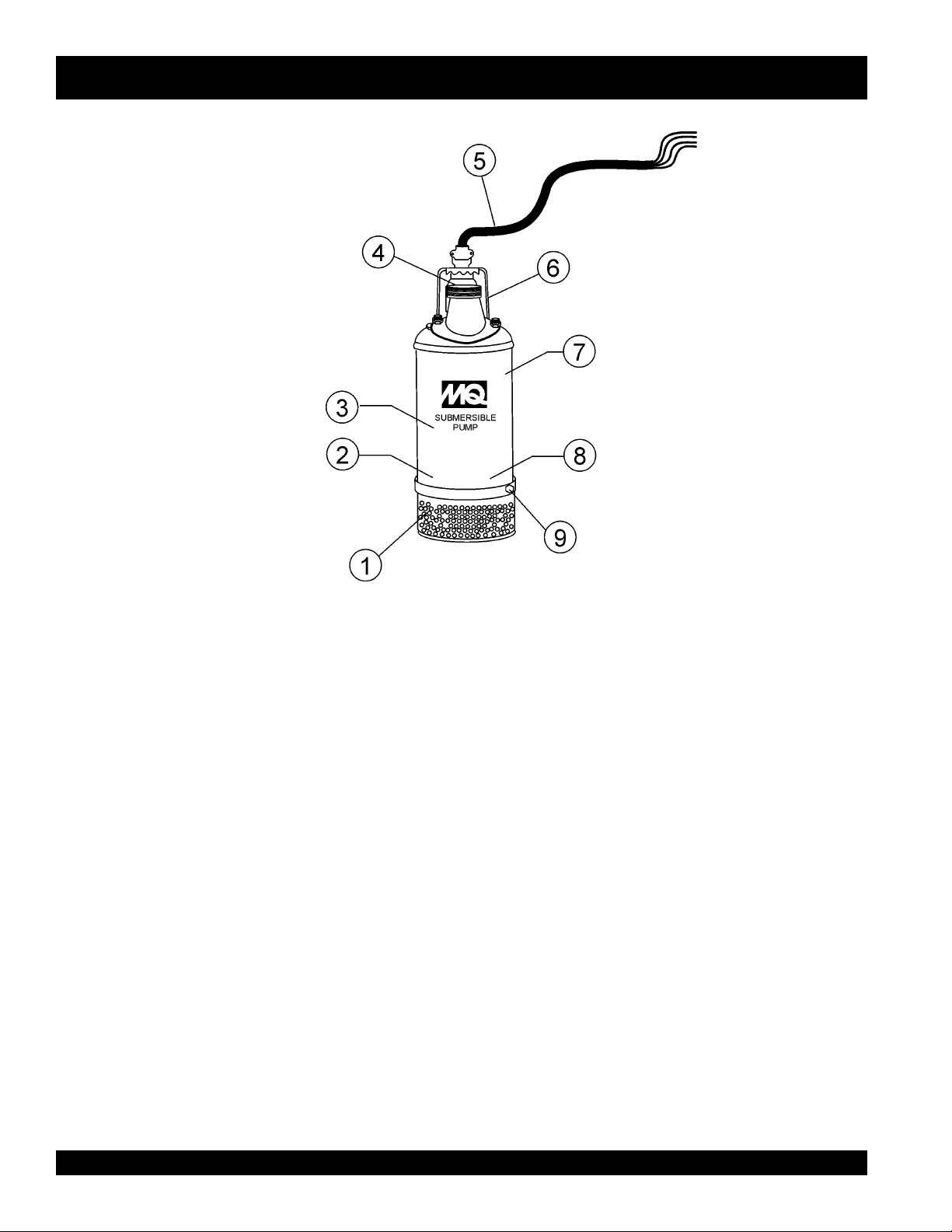
Figure 1. Submersible Pump Components
Figures 1 shows the location of the basic components, for the
ST-3050D Submersible Pump. Listed below is a brief explanation
of each component.
1. Strainer Base – This strainer base is made of stainless
steel which is resistant to hardware corrosion. DO NOT
pump large objects or debris with this pump. This pump is
for pumping water only. For de-watering purposes, always
place the strainer base on a platform.
2. Volute/Impeller – Impellers are constructed of high-chrome
ductile iron to minimizes wear and prolong service life.
3. Electric Motor – This unit utilizes a three-phase, 230/460
VAC, 5.0 HP electric motor. Consult with a licenced
electrician before connecting motor to a power source.
Observe all city and local safety codes.
4. Discharge Port – Connect a 3-inch hose to this port.
Remember to adequately support the discharge hose to
avoid stress on the pump.
5. AC Power Cable – This unit is supplied with a 50 ft. (15.24
meters) AC power cable. Always check the cable for signs
of wear. NEVER! use a defective power cable. Replace the
cable immediately if the cable is worn or defective.
6. Carrying Handle – Always carry the submersible pump
by its handle. NEVER! carry the pump by its power cord.
Carrying or lifting the pump by the power cord, will cause
undue stress on the cord, and ultimately the cord will
become dislodged from the pump.
7. Thermal Overload Protection – This pump will require
the use of an external control box with a thermal overload
protection device that will shut-down the motor in the event
of high operating temperatures. The motor will automatically
restart once the temperature returns to an acceptable
operating temperature.
8. Mechanical Oil Seal – This oil filled seal provides
lubrication when running the pump dry. NEVER! run the
pump dry. Running the pump dry will cause severe damage
to the pump.
9. Mechanical Oil Seal Plug – Remove this plug to check
and add hydraulic oil (Shell 32 or equivalent) to the oil
cavity. This oil protects the mechanical seal. Oil cavity should
be full enough to cover seal spring.
PAGE 10 — ST-3050D — PARTS & OPERATION MANUAL — REV. #1 (11/18/02)
Page 11
ST-3050D SUBMERSIBLE PUMP — APPLICATION (FLOAT SWITCHES)
CAUTION!
HIGH
VOLTAGE!
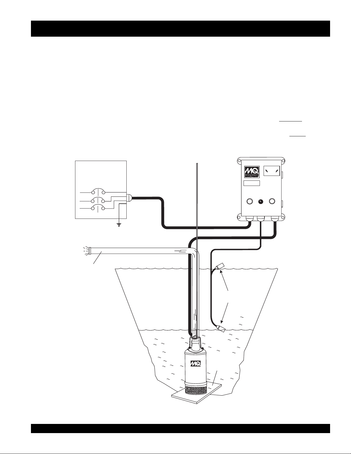
Float Switch Theory
There is a tilt-sensitive mercury switch hermetically sealed within
each float. As the liquid level (water) rises or falls, the float changes
its angle until the mercury switch makes (close) or breaks (open)
the circuit.
The length of cord between the float and point of attachment
determines the amount of water to be pumped.
Float Switch (Dual)
Float switches (Figure 2) are used for the unattended operation
of the submersible pump. The ST-3050D pump requires the use
of a control box to perform this function. Shown in Figure 2 is an
example of a dual float control switch application.
The Model ST-3050D submersible pump requires one each of
the Model SW-1WOP float type mercury switches. These
switches have a pumping range level between 5.5~18 feet
(1.67~5.5 meters). All float switch connections are bare wire (no
Contact Multiquip sales department to order float switches.
plug). The ST-3050D submersible pump
Control Box
application. The MCP102/104 control boxes
switch capability.
EXTERNAL 3-PHASE
(230 OR 460 VOLT)
POWER SOURCE
CIRCUIT
BREAKER
L1
L2
L3
GROUND
RED
WHITE
BLACK
GREEN
LIFTING
ROPE
must use the
CB 200
when float switches are required for the job
do not have float
CONTROL
BOX
CAUTION!
HIGH
VOLTAGE!
CB200
OFF
MANUAL
AUTO
FLOAT
SWITCH
INPUTS
RESET
AC
POWER
TO
PUMP
ON
AC
POWER
INPUT
3-INCH
DISCHARGE
HOSE
PUMP
FLOAT
SWITCHES
PUMP
OFF
SUPPORT
SUBMERSIBLE
PUMP
PLATFORM
Figure 2. Dual Float Control Switch
ON
ST-3050D — PARTS & OPERATION MANUAL — REV. 0 (11/18/02) — PAGE 11
Page 12
ST-3050D SUBMERSIBLE PUMP — CONTROL BOXES
CAUTION!
HIGH
VOLTAGE!
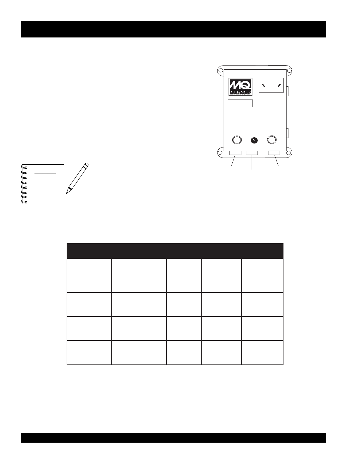
Control Boxes
Control boxes (Figure 3) are available for remote control and
thermal shut-down capability for the submersible pump. These
water resistant control boxes provide electronic overload
protection, watertight housing and glands to prevent water from
leaking into the box, and a float switch interface.
There are various control box models to choose from, reference
Table 2 for the model that meets your pumping requirements.
Contact Multiquip sales department to order control boxes as
listed in Table 2.
NOTE
ALWAYS
licensed electrician perform the
installation of the control box.
have a qualified
Figure 3. Electrical Control Box (CB-200)
AC POWER
INPUT
CONTROL
BOX
CB200
OFF
MANUAL
ON
FLOAT
SWITCH
INPUT
CAUTION!
VOLTAGE!
AUTO
HIGH
RESET
TO PUMP
002BC
201PCM
401PCM
.oNledoMepyTegatloV
snoitacifiepSxoBlortnoC.2elbaT
ASC/LU
detsiL
CAV064/032
esahP-eerhT
CAV032
esahP-eerhT
CAV064
esahP-eerhT
SEYSEYSEY
SEYSEYON
SEYSEYON
lamrehT
daolrevO
noitcetorP
taolF
hctiwS
ytilibapaC
PAGE 12 — ST-3050D — PARTS & OPERATION MANUAL — REV. #1 (11/18/02)
Page 13

ST-3050D SUBMERSIBLE PUMP/CTRL. BOX — INSTALLATION (CB200)
EZISERIWDNAHTGNELDROC.3ELBAT S
SPMA.TF05.TF001.TF051
6GWA61GWA61GWA41
8GWA61GWA41GWA21
01GWA61GWA41GWA21
21GWA41GWA41GWA21
41GWA41GWA21GWA01
61GWA21GWA21GWA01
DANGER:
POWER CORD REQUIREMENTS
When routing the three phase power via a power cord to the
control box,
Table 3 below (Cord Length/Wire Size) to determine the correct
wire size. Incorrect wire size can adversely affect the performance
of the pump.
To place the ST-3050D submersible pump into operation
requires the use of a control box. The control box contains the
necessary electronics (electronic overload module, float switch
connections and 230/460 voltage transformer) to operate the
pump. Remember this control box contains hazardous voltages.
Disconnect all sources of power before installing or servicing.
There exists the possibility of electrocution, electric shock or
burn, which can cause severe bodily harm or even
death
!
CAUTION:
This control box should only be installed or
serviced by a licensed electrician or qualified
personnel.
ALWAYS
use the correct wire size. Please reference
CONTROL BOX MOUNTING
Mount the control box in an
upright vertical position
the control box is securely fastened to a flat surface, that is free
of dust, dirt, moisture or any elements that may contaminate or
erode the electronic components of the control box.
3-Phase Power Installation (Input)
The ST-3050D submersible pump requires 230/460 3-phase
power for normal operation. The pump is shipped from the factory
in the 230 VAC configuration. To change the voltage setting from
230 VAC to 460 VAC refer to the transformer wiring section on
page 16.
If you cannot determine what your pump's power
requirements are, look at the vendor supplied identification
name tag attached to the pump or please contact Multiquip's
Service/Technical Assistance department.
CAUTION:
Applying incorrect power (
to the submersible pump can cause severe
damage to the pump. Please make sure that
the correct voltage and phase are transferred
to the pump at all times.
. Make sure
voltage phasing
)
FLOAT SWITCH INSTALLATION (CB200)
1. Remove the float switch input connector housing, then
route the float switch wires through the cable gland on the
control box. Attach the wires to the float switch terminal
block as indicated by Table 2. Reference Figures 7 and 8.
SNOITCENNOCHCTIWSTAOLF.4ELBAT S
HCTIWSTAOLF
TRATS2DNA1SLANIMRET
POTS4DNA3SLANIMRET
LANIMRETHCTIWSTAOLF
REBMUNKCOLB
2. Tighten the connector housing to ensure a tight fit between
the cord and the connector body. This will prevent the cable
from pulling out of the terminal block and also prevent
moisture from entering the control box..
3. Determine the length of the float switch wires, then secure
float switch wires to pump discharge hose.
ST-3050D — PARTS & OPERATION MANUAL — REV. 0 (11/18/02) — PAGE 13
Page 14

ST-3050D SUBMERSIBLE PUMP — 230/460 VAC VOLTAGE SELECTION
230/460 VAC Voltage Selection
The ST-3050D submersible pump is factory set at 230
VAC. To change the voltage from 230 VAC to 460 VAC,
perform the following:
1. Remove the four retaining screws that secure the power
cord gland assembly to the pump casing, and pull the 230
VAC female plug (Figure 4) from the pump's cavity.
2. Un-plug the 230 VAC female plug from the male motor
windings plug and insert the 460 VAC female plug into
male motor windings plug.
3. Re-install the power cord gland assembly back into the
pump's cavity. Make sure that the gland is seated correctly.
This will prevent any connector pins from bending or
breaking.
4. Insert the four retaining screws and tighten securely
Figure 4. 230/460 VAC Pump Voltage Selection
PAGE 14 — ST-3050D — PARTS & OPERATION MANUAL — REV. #1 (11/18/02)
Page 15

ST-3050D SUBMERSIBLE PUMP — PUMP WIRING DIAGRAM
Figure 5. Pump Wiring Diagram
ST-3050D — PARTS & OPERATION MANUAL — REV. 0 (11/18/02) — PAGE 15
Page 16

ST-3050D SUB. PUMP/CTRL. BOX — TRANSFORMER WIRING (CB200)
TRANSFORMER 230/460 VOLTAGE SETTINGS
CAUTION:
Transformer 230/460 Voltage Settings:
Pump motors are factory set at 230 VAC. The
transformer (Figure 6) of this control box
be set to the voltage requirements of the pump
in use. Refer to the attached wiring diagram
located inside the "Control Box" or reference Figures 7 & 8.
Use the two supplied
required output voltage.
NOTE
Transformer settings
are for CB 200 Control
Box only!
jumper tabs
to set the transformer to the
must
WARNING:
ALWAYS
to the correct output voltage. Incorrect transformer
output voltage settings can cause severe damage
to the pump.
make sure that the transformer is set
Figure 6. Transformer AC Voltage Settings (Jumper Tabs)
PAGE 16 — ST-3050D — PARTS & OPERATION MANUAL — REV. #1 (11/18/02)
Page 17

ST-3050D SUB. PUMP/CONTRL. BOX — WIRING DIAGRAM (CB200)
EXTERNAL 3-PHASE
(230 OR 460 VOLT)
POWER SOURCE
CIRCUIT
BREAKER
L1
L2
L3
WHITE
BLACK
GROUND
RED
GREEN
MANUAL
5
L2
XF
L1
L3
F1
FUSE
1/2 AMP
OFF
11
23
THREE PHASE WIRING
CONNECTIONS
H3
H1
X1
AUTO
1
12
4
24
H2
3
14 13
H4
CONTROL
TRANSFORMER
50VA CPT
6
X2
1
ELECTRONIC
OVERLOAD UNIT
T1
T2
T3
PUMP
MOTOR
TERMINALS
O/L
6
96
95
M
1
3
5
1
1
O/L
2
4
6
SEE FIGURE 1 FOR JUMPER SELECTION
230 0R 460 VAC SELECTION.
ON
INDICATOR
LAMP
7
G
CONTACTOR
5HP
7
M
A1
A2
WARNING
ONLYA LICENSED ELECTRICIAN
OR QUALIFIED PERSONNEL
SHOULD PERFORM WIRING AND
INSTALLATION OF THIS
CONTROL PANEL.
Float switch connections are for
NOTE
use with the CB200 Control Box
only!
TERMINAL
BLOCK
43 2
STOP
FLOAT
SWITCH
SWITCH
1
START
FLOAT
Figure 7. Control Box Wiring Diagram
NOTE:
1. REFER TO PAGE 20 OF THIS MANUAL
FOR THE CORRECT SETTING OF THE
ELECTRONIC OVERLOAD UNIT.
ST-3050D — PARTS & OPERATION MANUAL — REV. 0 (11/18/02) — PAGE 17
Page 18

ST-3050D SUB. PUMP/CTRL. BOX — 3Ø PWR. INSTALLATION (CB200)
3-PHASE POWER CORD (INPUT TO BOX) INSTALLATION
1. The three phase
input
power cord should have four wires.
Each wire is color coded. The colors are RED, WHITE,
BLACK and GREEN.
2. Remove the 3-phase AC input connector housing from the
control box, then route the three phase input power cable
through the cable gland on the control box. Attach the
wires to the AC terminal block inside the control box as
indicated by Table 5 and Figure 8.
SNOITCENNOCREWOPTUPNICAESAHP-3.5ELBAT
S
ROLOCERIWELBAC#KCOLBLANIMRETCA
DER1L
ETIHW2L
KCALB3L
NEERGDNUORG
3-PHASE POWER INSTALLATION (OUTPUT TO PUMP)
1. The three phase
Each wire is color coded. The colors are RED, WHITE,
BLACK and GREEN.
2. Remove the 3-phase AC output power connector housing
on the control box, then route the three phase output power
cable through the cable gland on the control box. Attach
the wires to the AC terminal blocks on the
overload
output
power cord should have four wires.
electronic
unit as indicated by Table 6 and Figure 8.
SNOITCENNOCREWOPTUPTUOCAESAHP-3.6ELBAT
S
ROLOCERIWELBAC
DER2
ETIHW4
KCALB6
DAOLREVOCINORTCELE
#KCOLBLANIMRETTINU
3. Tighten the connector housing to ensure a tight fit between
the power cord and the connector body. This will prevent
the cable from pulling out of the terminal block and also
prevent moisture from entering the control box.
It is recommended that the power being supplied to the control
box
ALWAYS
disconnect
of power from the control box in the event of an emergen
be connected to a
circuit breaker
or a
quick
switch. This safety feature allows for quick removal
cy.
NOTE
4. Connect the other end of the 3-phase input power cord to
the voltage source. Remember to provide a means of
disconnecting the power from the control box (circuit breaker
or quick disconnect switch). Also make sure to provide a
good earth ground to the control box.
NEERGDNUORG
Electrical connections to the power
source should only be performed by
licensed electrician
a
personnel.
or qualified
PAGE 18 — ST-3050D — PARTS & OPERATION MANUAL — REV. #1 (11/18/02)
Page 19

ST-3050D SUB. PUMP/CTRL BOX — 3Ø PWR. INSTALLATION (CB200)
Figure 8. Three Phase
Control Box/Pump System Diagram
ST-3050D — PARTS & OPERATION MANUAL — REV. 0 (11/18/02) — PAGE 19
Page 20

ST-3050D SUBMERSIBLE PUMP/CTRL. BOX — PRE SETUP (CB200)
ELECTRONIC OVERLOAD UNIT SETTINGS
Class Dial Setting
1. Set the CLASS dial pointer (Figure 9) to the HAND position
CAUTION:
Electronic Overload Unit: Always make sure that
the electronic unit supplied with the control box is set
to the correct amperage. This overload unit must
MATCH the amperage requirements of the pump
motor.
Using an electronic overload unit with incorrect settings may result in
serious damage to the pump. Refer to the Pump Amperage
Requirements Table (Table 7), for the correct overload amperage
settings.
There are two dials on the Electronic Overload Unit (Figure 9) that
require adjustment to meet the amperage requirement of the pump
motor in use.
These dials are located on top of the overload unit and are labeled
CLASS and FLC (A).
Use a phillips-head screw driver to adjust the dials to the correct
settings.
FLC (A) Dial Setting
1. Set the FLC (A) dial pointer (Figure 9) to the correct
amperage for the pump motor in use. Use Table 7, to
determine the correct amperage setting.
10. This controls the reset function only. It does not affect
the ability of the pump to run with or without float switches.
RESET Operation
This electronic control unit has two modes of reset. The modes are
defined as follows:
MODE 1
When the CLASS dial on the electronic overload module is in the HAND
position (manual) the reset button (Figure 10) on the front of the control
box must be
an overload.
MODE 1
When the CLASS dial on the electronic overload module is in the AUTO
position (automatic mode) the unit will automatically be reset in the
event of an overload
pushed
to reset the unit (restore power) in the event of
Figure 10. Control Box Reset Button
Figure 9. Electronic Overload Module
STNEMERIUQEREGAREPMAROTOMPMUP.7ELBAT
S
ledoMpmuP
D0503TS
esahP-eerhT
D0503TS
esahP-eerhT
lortnoC
xoB
002BC0322.41A61-04.6-610EXA
002BC0641.7A61-04.6-610EXA
stloV
)CAV(
spmAtinUdaolrevO
NOTE
All Multiquip
control boxes
should
have the CLASS dial set to the HAND
position 10.
Operation
1. From the voltage source set the circuit breaker or quick
disconnect switch to the ON position.
2. For manual operation of the pump, place the 3-position
operation switch (Figure 11) on the control box in the
MANUAL position.
Figure 11. Manual-Off-On SW. (Man Position)
PAGE 20 — ST-3050D — PARTS & OPERATION MANUAL — REV. #1 (11/18/02)
Page 21

ST-3050D SUBMERSIBLE PUMP/CTRL. BOX — PRE SETUP (CB-200)
3. Verify that the ON indicator (Figure 12) on the control box
is LIT. This means that power is being supplied to the control
box.
Figure 12. Control Box Power ON Indicator
4. In the manual mode the pump will run continuously. Pay
close attention when running the pump in this mode.
DAMAGE to the pump may occur if pump is not immersed
in water.
5. To operate the pump automatically (float switches), place the
3-position operation switch in the AUTO position (Figure 13).
Figure 13. Manual-Off-On SW. (Auto Position)
Shut-Down
1. Place the 3-position operation switch on the control box to
the OFF position (Figure 14).
Figure 14. Manual-Off-On SW. (OFF Position)
2. Verify that the control box power ON light is OFF.
3. Turn the circuit breaker or quick disconnect switch to the
OFF position.
6. In the AUTO mode the pump will run as long as there is a
sufficient amount of water. This amount is determined by
the setting of the float switches. The
contacts will open when the water level is low and power
will be removed from the pump's motor.
Once the water level has risen back to the appropriate
level the
will be restored to the pump's motor.
start float
switch contacts will close and power
stop float
switch
ST-3050D — PARTS & OPERATION MANUAL — REV. 0 (11/18/02) — PAGE 21
Page 22

ST-3050D SUB. PUMP/CTRL. BOX — INSTALLATION (MCP102/104)
DANGER:
It is recommended that the power being supplied to the control
ALWAYS
box
disconnect
of power from the control box in the event of an emergen
4. Connect the other end of the 3-phase input power cord to
the voltage source. Remember to provide a means of
Remember this control box contains hazardous voltages.
Disconnect all sources of power before installing or servicing.
There exists the possibility of electrocution, electric shock or
burn, which can cause severe bodily harm or even
Remember the
230 VAC 3-phase applications and the
is for 460 VAC 3-phase applications. Neither control box has
float switch capability.
MCP102 Control Box
is to be used only for
MCP 104 Control Box
death
!
disconnecting the power from the control box (circuit breaker
or quick disconnect switch). Also make sure to provide a
good earth ground to the control box.
ELECTRONIC OVERLOAD SETTING (230 VAC, 3Ø)
1. Using a small flat-blade screwdriver, set the
amperage dial pointer on the electronic
overload unit to 14.2 amps.
POWER CORD REQUIREMENTS
When routing the three phase power via a power cord to the
control box,
ALWAYS
use the correct wire size. Please reference
Table 3 (Cord Length/Wire Size) to determine the correct wire
size. Incorrect wire size can adversely affect the performance of
ELECTRONIC OVERLOAD SETTING (460 VAC, 3Ø)
1. Using a small flat-blade screwdriver,set the
amperage dial pointer on the electronic
overload unit to 7.1 amps.
the pump.
be connected to a
circuit breaker
or a
quick
switch. This safety feature allows for quick removal
cy.
6.3
5.1
14.2
6.3
5.1
7.1
CONTROL BOX MOUNTING
Mount the control box in an
upright vertical position
. Make sure
the control box is securely fastened to a flat surface, that is free
of dust, dirt, moisture or any elements that may contaminate or
erode the electronic components of the control box.
3-PHASE POWER CORD (INPUT TO BOX) INSTALLATION
1. The three phase
input
power cord should have four wires.
Each wire is color coded. The colors are RED, WHITE,
BLACK and GREEN.
2. Remove the 3-phase AC input connector housing from the
control box, then route the three phase input power cable
through the cable gland on the control box. Attach the
3-PHASE POWER INSTALLATION (OUTPUT TO PUMP)
1. The three phase
Each wire is color coded. The colors are RED, WHITE,
BLACK and GREEN.
2. Remove the 3-phase AC output power connector housing
on the control box, then route the three phase output power
cable through the cable gland on the control box. Attach
the wires to the AC terminal blocks on the
overload
wires to the terminal block on the electronic overload unit
inside the control box as indicated by Table 5 and Figure 15.
3. Tighten the connector housing to ensure a tight fit between
the power cord and the connector body. This will prevent
the cable from pulling out of the terminal block and also
prevent moisture from entering the control box.
output
power cord should have four wires.
electronic
unit as indicated by Table 6 and Figure 15.
PAGE 22 — ST-3050D — PARTS & OPERATION MANUAL — REV. #1 (11/18/02)
Page 23

HIGH
VOLTAGE
ST-3050D SUB. PUMP/CTRL. BOX — WIRING DIAGRAM (MCP102/104)
HIGH
VOLTAGE
AC POWER
INPUT
CONTROL
BOX
CAUTION
HIGH
VOLTAGE
MCP102
(230 VAC, 3Ø)
EXTERNAL 3-PHASE
L1
L2
L3
TO PUMP
(230/460 VAC)
POWER SOURCE
CIRCUIT
BREAKER
POWER CABLE
MOUNT CONTROL
BOX IN AN UPRIGHT
VERTICAL POSITION
AS SHOWN.
RED
WHITE
BLACK
GREEN
GROUND
3 PHASE
AC INPUT
BLACK
AC POWER
INPUT
MCP102/MCP104
3/L2
1/L1
6.3
5.1
4
STOP
SET TO
14.2 AMPS
WHITE
RED
TEST
2/T1 4/T2 6/T3
RED
WHITE
5/L3
START
ELECTRONIC
OVERLOAD
TERMINAL
BLACK
CONTROL
BOX
CAUTION
HIGH
VOLTAGE
UNIT
TERMINAL
BLOCK
BLOCK
MCP104
(460 VAC, 3Ø)
TO PUMP
3 PHASE
AC POWER
INPUT
GREEN
GROUND
GREEN
3 PHASE
AC OUTPUT
POWER CABLE
WARNING
INSTALLATION IS TO BE PREFORMED
ONLY BY A LICENSED ELECTRICIAN
OR QUALIFIED PERSONNEL.
ST-3050D
SUBMERSIBLE
PUMP
Figure 15. MCP102/104 Control Box Configurations
3 PHASE
AC POWER
OUTPUT
ST-3050D — PARTS & OPERATION MANUAL — REV. 0 (11/18/02) — PAGE 23
Page 24

Operation
ST-3050D SUBMERSIBLE PUMP — OPERATION
1. Attach a suitable lifting cable (rope) to the carrying handle
(Figure 16) on the pump and lower the pump into place. For
applications where there is an excessive amount of mud, grit
or silt, the use of a support platform is desirable. When
pumping water from swimming pool type applications where
2. Make sure the pump is always placed in an upright position,
not tilted (Figure 17). Never position the pump directly on a
soft, loose bottom. Remember to attain maximum pumping
capacity and prevent excessive wear, position the pump so
it will not burrow itself into sand or clay.
there is little or no debris, the support platform is not required.
POWER
CORD
LIFTING
ROPE
3-INCH
DISCHARGE
HOSE
CARRYING
HANDLE
SUBMERSIBLE
PUMP
SUBMERSIBLE
PUMP
SUPPORT
PLATFORM
Figure 16. Submersible Pump Upright Position
(Correct)
Figure 17. Submersible Pump Upright Position
(Incorrect)
3. After the pump has been positioned correctly into place,
power can be applied to the pump's electric motor.
PAGE 24 — ST-3050D — PARTS & OPERATION MANUAL — REV. #1 (11/18/02)
Page 25

ST-3050D SUBMERSIBLE PUMP — OPERATION
4. NEVER! grab or touch a live power cord (Figure 18) with wet
hands, the possibility exists of
and even
tion
(POWER ON)
DANGER:DANGER:
DANGER:
DANGER:DANGER:
death
.
POWER
CORD
Figure 18. Power Cord (Wet Hands)
NEVER! grab or touch a live power cord. DO
NOT stand in water when connecting the
pump's power cord into a voltage source. The
possibility exist of electrical shock, electrocution
and possibly
electrical shock, electrocu-
WET
HANDS
death!
Pump Shut-Down/Clean-up
1. Remove the power from the pump by turning off the circuit
breaker or switch that provides power to the pump. Remember to make sure that hands are dry (not wet), and feet are not
standing in water when removing disconnecting power from
the pump.
2. Using the lifting rope, lift the pump up from its current position.
Remove the discharge hose from the discharge port on the
pump.
3. Remove all power cables and float switches from the control
box. Place cables and float switches in a suitable container
where they will not get damaged.
4. If the pump was used to pump mud, grit or silt, flush vigorously
with clean water.
5. Remove the pump from the water. Wipe off any mud or debris
that might have attached itself to the pump.
6. Store pump in a clean dry place away from dirt and debris.
3. If all of the pump's electrical requirements have been met,
insert the power plug on the pump into the power source
receptacle.
4. Wait a few seconds and water should begin to flow from the
discharge hose.
5. If water is not flowing from the discharge hose or not flowing
freely after a few minutes, remove the power from the pump
and check the system for leaks.
ST-3050D — PARTS & OPERATION MANUAL — REV. 0 (11/18/02) — PAGE 25
Page 26

ST-3050D SUBMERSIBLE PUMP — MAINTENANCE
LUBRICATION
To check the oil level of the mechanical seal perform the
following:
1. Lay the pump (Figure 19) on its side with the oil plug facing
upwards.
2. Remove oil fill plug.
3. Visually inspect oil plug hole to verify that oil cavity is full
enough to cover seal spring. Check every 300 hours, change
hydraulic oil every 6 months (1,000 hours) or as needed.
4. While checking the hydraulic oil level, also check the
condition of the hydraulic oil in the seal cavity . Block the
opening with a finger and roll pump to one side to drain
oil into a small transparent container. If oil is cloudy or has
water in it, drain oil from pump cavity and replace hydraulic oil. Check the seal for wear damage.
5. If oil level is low fill with SAE 10 weight non-detergent
hydraulic oil (i.e. Shell Turbo 32 or equivalent). Fill oil cavity
75% to 85% full (allow air space for expansion). Pump oil
cavity capacity is approximately 180 cc.
IMPELLER
1. Make sure the clearance between the impeller and the
friction disk is approximately .012 - .020 inches (.304 - .508
mm.)
2. If impeller is defective or badly worn, replace impeller immediately.
Figure 19. Checking Hydraulic Oil
PAGE 26 — ST-3050D — PARTS & OPERATION MANUAL — REV. #1 (11/18/02)
Page 27

ST-3050D SUBMERSIBLE PUMP — TROUBLESHOOTING
GNITOOHSELBUORTPMUP.XELBAT
MOTPMYS MELBORPELBISSOP NOITULOS
?spma/egatlovtcerrocnI
?snoitcennoclacirtcelekcehC
?esufrewopnwolB
tratSoTsliaFpmuP
?esoh
lluFrevileDotsliaFpmuP
tuptuO
?dekcolrellepmI
?sgnidniwrotomteW
?sgniraeb
?egatlovwoL
pmupdnarotomevitcefeD
.evitcefedfirotom
egrahcsiddetcirtserrodetsiwT
?reniartspmupdeggolC .reniartsnaelC
.htgnelderiuqerehtrofyticapac
.esufnwolbfoesuackcehc,esufecalpeR
.mehtyrdotsgnidniwekabdnarotompmup
.drocrewoptcepsni,gniriwkcehcsehctiwstaolfgnisufI
.enilesohmorfgolcevomeR.deknik-nutalfesohyaL
ehtotdeilppusgniebsi)Ø3064/032(egatlovreporptahtkcehC
tnerrucfotnuomaetauqedanasierehttahtkcehcoslA.pmup
.rekaerbtiucricecruosrewopkcehC.pmupehtnurot)spma(
rellepmireporpmidnagniggolcrofkcehcdnadrocrewoptcennocsiD
.ecivednoitcetorpdaolrevokcehC.pmupgolcnU.ecnaraelc
tsumecnatsisernoitalusnI.noitalusnirotomkcehcotretemitlumesU
elbmessasid,wolsiecnatsiserfI.smhoagem51yletamixorppaeb
ecalpeR.sgniraebecalpernrowfi,raewgniraebevissecxerofkcehC
egatloV.dezigrenesipmupelihwegatlovkcehcotretemtlovaesU
nafI.)daoldnadaolon(ecruosrewopkcehC.%01±nihtiwebtsum
gniyrrac-tnerrucetauqedasahtierusekam,desusidrocnoisnetxe
liOlaeSniretaW
Figure 20.
Performance Chart
90
Total Head (Feet)
60
30
?nrowrellepmI .rellepmiecalpeR
?laesretawevitcefeD .laesretawecalpeR
?gulPlliFliOesooL .ylerucesnethgiT
Performance Curve
TOTAL HEAD
Max 86 ft
CAPACITY
Max 264 G.P.M
0
100
200
300
Capacity(US.G.P.M)
ST-3050D — PARTS & OPERATION MANUAL — REV. 0 (11/18/02) — PAGE 27
Page 28

EXPLANATION OF CODE IN REMARKS COLUMN
How to read the marks and remarks used in this parts
book.
Items Found In the “Remarks” Column
Serial Numbers-Where indicated, this indicates a serial
number range (inclusive) where a particular part is used.
Model Number-Where indicated, this shows that the
corresponding part is utilized only with this specific model
number or model number variant.
Items Found In the “Items Number” Column
NOTE
The contents of this
parts catalog are
subject to change
without notice.
All parts with same symbol in the number column,
■
, belong to the same assembly or kit.
NOTE
If more than one of the same
reference number is listed,
the last one listed indicates
newest (or latest) part
available.
, #, +, %, or
*
PAGE 28 — ST-3050D — PARTS & OPERATION MANUAL — REV. #1 (11/18/02)
Page 29

ST-3050D — SUGGESTED SPARE PARTS
ST-3050D SUBMERSIBLE PUMP 1 TO 3 UNITS
1 to 3 Units
Qty......... P/N .............................. Description
1 ............ 0203050120 ................ AC CORD W/CORD GLAND
1 ............ 0203050060 ................ MECHANICAL SEAL
1 ............ 0203050081 ................ OIL SEAL
1 ............ 0203050047 ................ LINER
1 ............ 0203050003 ................ IMPELLER
1 ............ 0202020004 ................ IMPELLER NUT
2 ............ 0203050214 ................ PACKING
1 ............ 0202020157 ................ PACKING
1 ............ 0202020435 ................ PACKING
1 ............ 0202020435 ................ SPRING WASHER
ST-3050D — PARTS & OPERATION MANUAL — REV. 0 (11/18/02) — PAGE 29
Page 30

ST-3050D — ELECTRIC SUBMERSIBLE PUMP ASSY.
ELECTRIC SUBMERSIBLE PUMP ASSY.
PAGE 30 — ST-3050D — PARTS & OPERATION MANUAL — REV. #1 (11/18/02)
Page 31

ST-3050D — ELECTRIC SUBMERSIBLE PUMP ASSY.
ELECTRIC SUBMERSIBLE PUMP ASSY.
NO PART NO PART NAME QTY. REMARK
1 0203050001 CASING 1
2 0203050002 FRICTION DISC. 1
3 0203050003 IMPELLER 1
4 0202020004 IMPELLER NUT 1
5 0202020005 SPRING WASHER 1
6 0203050006 IMPELLER KEY 1
31 0202020031 STUD BOLT 4
32 0202020032 NUT 4
33 0202020033 WASHER 4
47 0203050047 LINER 1
53 0202020053 WASHER 1
60 0203050060 MECHANICAL SEAL 1
65 0202020065 PLUG 1
81 0203050081 OIL SEAL 1
102 0203050102 DISCHARGE PORT 1
103 0203050103 PACKING 1
104 0203050104 STUD BOLT 2
116 0202020116 BOLT 3
119 0203050119 MOTOR ........................................ 1 .................... ST-3050
119 0203050D119 MOTOR ........................................ 1 .................... ST-3050D
120 0203050120 AC CORD W/CORD GLAND 1
121 0202020121 CORD CLAMP 1
127 0202020127 CARRYING HANDLE 1
128 0202020128 BOLT 2
146 0203050146 STRAINER 1
147 0203050147 STUD BOLT 4
148 0203050148 SPRING WASHER 4
156 0203050156 HEAD COVER 1
157 0202020157 PACKING 1
160 0203050160 SLEEVE 1
174 0203050174 OUTER PIPE 1
188 0203050188 STRAINER SET PIPE 4
191 0202020191 POWER CORD GLAND CASE 1
192 0202020192 BOLT 4
214-1 0203050214 PACKING 1
214-2 0203050214 PACKING 1
ST-3050D — PARTS & OPERATION MANUAL — REV. 0 (11/18/02) — PAGE 31
Page 32

ST-3050 D— ELECTRIC SUBMERSIBLE PUMP ASSY.
PAGE 32 — ST-3050D — PARTS & OPERATION MANUAL — REV. #1 (11/18/02)
Page 33

ST-3050D — ELECTRIC SUBMERSIBLE PUMP ASSY.
ELECTRIC SUBMERSIBLE PUMP ASSY.
NO PART NO PART NAME QTY. REMARK
222 0203050222 NUT 4
224 0202020224 PLUG 1
431 0203050431 NUT 2
434 0203050434 STUFFING BOX 1
435 0202020435 PACKING 1
436 0202020436 SPRING WASHER 2
437 0202020437 CORD GLAND CASE COVER 1
438 0202020438 BOLT 3
439 0202020439 PACKING 1
440 0202020440 CONNECTOR 1
441 0202020441 PACKING 1
442 0202020442 BOLT 3
443 0202020443 WASHER 3
444 0202020444 BOLT 2
613 0203050D613 CONNECTOR CASE 1 ST-3050D
614 0203050D614 BOLT 4 ST-3050D
615 0203050D615 PACKING 1 ST-3050D
616 0203050D616 PLUG 1 ST-3050D
617 0203050D617 GLAND RUBBER 1 ST-3050D
618 0203050D618 GLAND METAL 1 ST-3050D
619 0203050D619 BOLT 3 ST-3050D
620-1 0203050D620A CONNECTOR 1 ST-3050D
620-2 0203050D620B CONNECTOR 1 ST-3050D
ST-3050D — PARTS & OPERATION MANUAL — REV. 0 (11/18/02) — PAGE 33
Page 34

ELECTRIC MOTOR ASSY.
ST-3050D — ELECTRIC MOTOR ASSY.
PAGE 34 — ST-3050D — PARTS & OPERATION MANUAL — REV. #1 (11/18/02)
Page 35

ST-3050D — ELECTRIC MOTOR ASSY.
ELECTRIC MOTOR ASSY.
NO PART NO PART NAME QTY. REMARK
131 0203050131 BOLT 4
132 0202020B132 WASHER, LOCK 4
268 0203050268 MOTOR A BRACKET 1
269 0203050269 MOTOR B BRACKET 1
270 0203050270 MOTOR ROTOR 1
273 0203050D273 MOTOR STATOR 1
322 0202020B322 NUT 4
540 0203050540 A PACKING 1
541 0203050541 B PACKING 1
606 0203050606 A BEARING, MOTOR 1
607 0203050607 B BEARING, MOTOR 1
608 0202020B608 WASHER, WAVE 1
ST-3050D — PARTS & OPERATION MANUAL — REV. 0 (11/18/02) — PAGE 35
Page 36

Effective: October 1, 2002
TERMS AND CONDITIONS OF SALE — PARTS
PAYMENT TERMS
Terms of payment for parts are net 10 days.
FREIGHT POLICY
All parts orders will be shipped collect or
prepaid with the charges added to the invoice.
All shipments are F.O.B. point of origin.
Multiquip’s responsibility ceases when a signed
manifest has been obtained from the carrier,
and any claim for shortage or damage must be
settled between the consignee and the carrier.
MINIMUM ORDER
The minimum charge for orders from Multiquip is $15.00 net. Customers will be asked
for instructions regarding handling of orders
not meeting this requirement.
RETURNED GOODS POLICY
Return shipments will be accepted and credit
will be allowed, subject to the following provisions:
1. A Returned Material Authorization must
be approved by Multiquip prior to shipment.
2. To obtain a Return Mater ial Authorization,
a list must be provided to Multiquip Parts
Sales that defines item numbers, quantities, and descriptions of the items to be
returned.
a. The parts numbers and descriptions
must match the current parts price
list.
b. The list must be typed or computer
generated.
c. The list must state the reason(s) for
the return.
d. The list must reference the sales
order(s) or invoice(s) under which the
items were originally purchased.
e. The list must include the name and
phone number of the person requesting the RMA.
3. A copy of the Return Material Authorization must accompany the return shipment.
4. Freight is at the sender’s expense. All
parts must be returned freight prepaid to
Multiquip’s designated receiving point.
5. Parts must be in new and resalable con-
6. The following items are not returnable:
7. The sender will be notified of any material
8. Such material will be held for five working
9. Credit on returned parts will be issued at
10. In cases where an item is accepted, for
11. Credit issued will be applied to future
PRICING AND REBATES
Prices are subject to change without prior
notice. Price changes are effective on a specific date and all orders received on or after that
date will be billed at the revised price. Rebates
for price declines and added charges for price
increases will not be made for stock on hand
at the time of any price change.
Multiquip reserves the right to quote and sell
dition, in the original Multiquip package (if
any), and with Multiquip part numbers
clearly marked.
a. Obsolete parts. (If an item is in the
price book and shows as being replaced by another item, it is obsolete.)
b. Any parts with a limited shelf life
(such as gaskets, seals, “O” rings,
and other rubber parts) that were purchased more than six months prior to
the return date.
c. Any line item with an extended dealer
net price of less than $5.00.
d. Special order items.
e. Electrical components.
f. Paint, chemicals, and lubricants.
g. Decals and paper products.
h. Items purchased in kits.
received that is not acceptable.
days from notification, pending instructions. If a reply is not received within five
days, the material will be returned to the
sender at his expense.
dealer net price at time of the original
purchase, less a 15% restocking charge.
which the original purchase document
can not be determined, the price will be
based on the list price that was effective
twelve months prior to the RMA date.
purchases only.
direct to Government agencies, and to Original
Equipment Manufacturer accounts who use
our products as integral parts of their own
products.
SPECIAL EXPEDITING SERVICE
A $35.00 surcharge will be added to the invoice
for special handling including bus shipments,
insured parcel post or in cases where Multiquip
must personally deliver the parts to the carrier.
LIMITATIONS OF SELLER’S LIABILITY
Multiquip shall not be liable hereunder for
damages in excess of the purchase price of the
item with respect to which damages are
claimed, and in no event shall Multiquip be
liable for loss of profit or good will or for any
other special, consequential or incidental dam-
ages.
LIMITATION OF WARRANTIES
No warranties, express or implied, are made
in connection with the sale of parts or trade
accessories nor as to any engine not manufac-
tured by Multiquip. Such warranties made in
connection with the sale of new, complete units
are made exclusively by a statement of war-
ranty packaged with such units, and Multiquip
neither assumes nor authorizes any person to
assume for it any other obligation or liability
whatever in connection with the sale of its
products. Apart from such written statement of
warranty, there are no warranties, express,
implied or statutory, which extend beyond the
description of the products on the face hereof.
PAGE 36 — ST-3050D — PARTS & OPERATION MANUAL — REV. #1 (11/18/02)
Page 37

NOTE PAGE
ST-3050D — PARTS & OPERATION MANUAL — REV. 0 (11/18/02) — PAGE 37
Page 38

PARTS AND OPERATION MANUAL
HERE'S HOW TO GET HELP
PLEASE HAVE THE MODEL AND SERIAL NUMBER
ON-HAND WHEN CALLING
PARTS DEPARTMENT
800/427-1244 or 310/537-3700
FAX: 800/672-7877 or 310/637-3284
SERVICE DEPARTMENT
800/478-1244 or 310/537-3700
FAX: 310 - 537-4259
WARRANTY DEPARTMENT
800/421-1244, EXT. 279 or 310/537-3700
FAX: 310 - 537-1173
MAIN
800/421-1244 or 310/537-3700
FAX: 310 - 537-3927
MULTIQUIP INC.
18910 WILMINGTON AVENUE
CARSON, CALIFORNIA 90746
310 - 537-3700
800/421-1244 NATIONWIDE
FAX: 310 - 537-3927
PARTS DEPARTMENT:
800/427-1244
FAX: 800/672-7877
SERVICE DEPARTMENT:
800/478-1244
FAX: 310 - 537- 4259
 Loading...