

Page 1

OPERATION MANUAL
MODEL SP2S20H
SELF-PROPELLED
PROFESSIONAL PAVEMENT SAW
(HONDA GX630RTXF2 GASOLINE ENGINE)
Revision #1 (02/17/2012)
To find the latest revision of this
publication, visit our website at:
www.multiquip.com
THIS MANUAL MUST ACCOMPANY THE EQUIPMENT AT ALL TIMES.
PN: 35523
Page 2

PROPOSITION 65 WARNING
Engine exhaust and some of
its constituents, and some dust created
by power sanding, sawing, grinding,
drillingandotherconstructionactivities
contains chemicals known to the State
of California to cause cancer, birth
defects and other reproductive harm.
Some examples of these chemicals are:
Leadfromlead-basedpaints.
Crystallinesilicafrombricks.
Cementandothermasonryproducts.
Arsenicandchromiumfrom chemically
treatedlumber.
Your risk from these exposures varies,
dependingonhowoftenyoudothistype
of work. To reduce your exposure to
these chemicals: work in aALWAYS
well ventilated area, and work with
approved safety equipment, such as
dust masks that are specially designed
to filter out microscopic particles.
PAGE 2 — SP2S20H PAVEMENT SAW • OPERATION MANUAL — REV. #1 (02/17/12)
Page 3
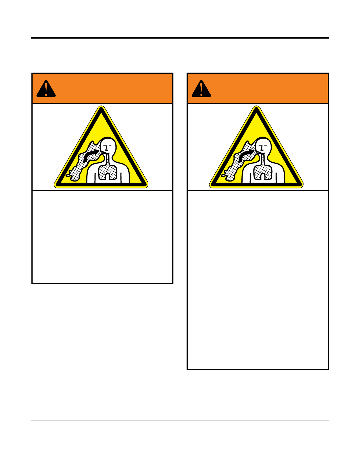
SILICOSIS/RESPIRATORY WARNINGS
WARNING
SILICOSIS WARNING RESPIRATORY HAZARDS
Grinding/cutting/drilling of masonry, concrete, metal and
other materials with silica in their composition may give
off dust or mists containing crystalline silica. Silica is a
basic component of sand, quartz, brick clay, granite and
numerous other minerals and rocks. Repeated and/or
substantial inhalation of airborne crystalline silica can
cause serious or fatal respiratory diseases, including
silicosis. In addition, California and some other
authorities have listed respirable crystalline silica as a
substance known to cause cancer. When cutting such
materials, always follow the respiratory precautions
mentioned above.
WARNING
Grinding/cutting/drilling of masonry, concrete, metal and
other materials can generate dust, mists and fumes
containing chemicals known to cause serious or fatal
injury or illness, such as respiratory disease, cancer,
birth defects or other reproductive harm. If you are
unfamiliar with the risks associated with the particular
process and/or material being cut or the composition of
the tool being used, review the material safety data
sheet and/or consult your employer, the material
manufacturer/supplier, governmental agencies such as
OSHA and NIOSH and other sources on hazardous
materials. California and some other authorities, for
instance, have published lists of substances known to
cause cancer, reproductive toxicity, or other harmful
effects.
Control dust, mist and fumes at the source where
possible. In this regard use good work practices and
follow the recommendations of the manufacturers or
suppliers, OSHA/NIOSH, and occupational and trade
associations. Water should be used for dust
suppression when wet cutting is feasible. When the
hazards from inhalation of dust, mists and fumes cannot
be eliminated, the operator and any bystanders should
always wear a respirator approved by NIOSH/MSHA for
the materials being used.
SP2S20H PAVEMENT SAW • OPERATION MANUAL — REV. #1 (02/17/12) — PAGE 3
Page 4

SP2S20H Pavement Saw
Proposition 65 Warning ........................................... 2
Silicosis/Respiratory Warnings ................................ 3
Table Of Contents .................................................... 4
Training Checklist .................................................... 6
Daily Pre-Operation Checklist ................................. 7
Safety Information ..............................................8-14
Specifications ...................................................15-16
Dimensions ............................................................ 17
General Information ............................................... 18
Components ..................................................... 19-20
Basic Engine .......................................................... 21
Inspection ......................................................... 22-28
Startup ................................................................... 29
Startup ................................................................... 30
Operation .......................................................... 31-33
Maintenance ..................................................... 34-44
Engine Wiring Diagram .......................................... 45
Troubleshooting ................................................ 46-48
TABLE OF CONTENTS
NOTICE
Specifications are subject to change without notice.
PAGE 4 — SP2S20H PAVEMENT SAW • OPERATION MANUAL — REV. #1 (02/17/12)
Page 5

NOTES
SP2S20H PAVEMENT SAW • OPERATION MANUAL — REV. #1 (02/17/12) — PAGE 5
Page 6

TRAINING CHECKLIST
Training Checklist
No, Description OK? Date
1
2
3 Fuel system, refueling procedure.
4 Operation of spray and lights.
5
6
7 Emergency stop procedures.
8
9 Forward and reverse travel.
10 Starting a cut.
11 Pavement cutting techniques.
12 Stopping a cut.
Read operation manual
completely.
Machine layout, location of
components, checking of engine
and hydraulic oil levels.
Operation of controls (machine
not running).
Safety controls, safety stop switch
operation.
Startup of machine, pre-heat,
engine choke.
13
14 Shutdown of machine.
15 Lifting of machine (lift loops).
16 Machine transport and storage.
Restart after stopping blade within
work surface — explanation
PAGE 6 — SP2S20H PAVEMENT SAW • OPERATION MANUAL — REV. #1 (02/17/12)
Page 7

DAILY PRE-OPERATION CHECKLIST
Daily Pre-Operation Checklist
1 Hardware and damage check
2 Engine oil level
3 Hydraulic oil level
4 Condition of blade
5 Safety stop switch operation
6 Braking control operation
SP2S20H PAVEMENT SAW • OPERATION MANUAL — REV. #1 (02/17/12) — PAGE 7
Page 8
SAFETY INFORMATION
Do not operate or service the equipment before reading
Potential hazards associated with the operation of this
the entire manual. Safety precautions should be followed
at all times when operating this equipment.
Failure to read and understand the safety
messages and operating instructions could
result in injury to yourself and others.
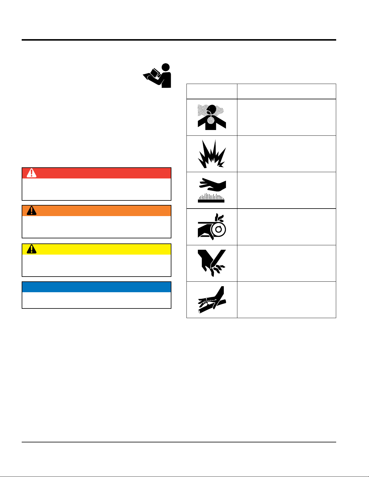
SAFETY MESSAGES
The four safety messages shown below will inform you
about potential hazards that could injure you or others. The
safety messages specifi cally address the level of exposure
to the operator and are preceded by one of four words:
DANGER, WARNING, CAUTION or NOTICE.
SAFETY SYMBOLS
DANGER
Indicates a hazardous situation which, if not avoided,
WILL result in DEATH or SERIOUS INJURY.
WARNING
Indicates a hazardous situation which, if not avoided,
COULD result in DEATH or SERIOUS INJURY.
equipment will be referenced with hazard symbols which
may appear throughout this manual in conjunction with
safety messages.
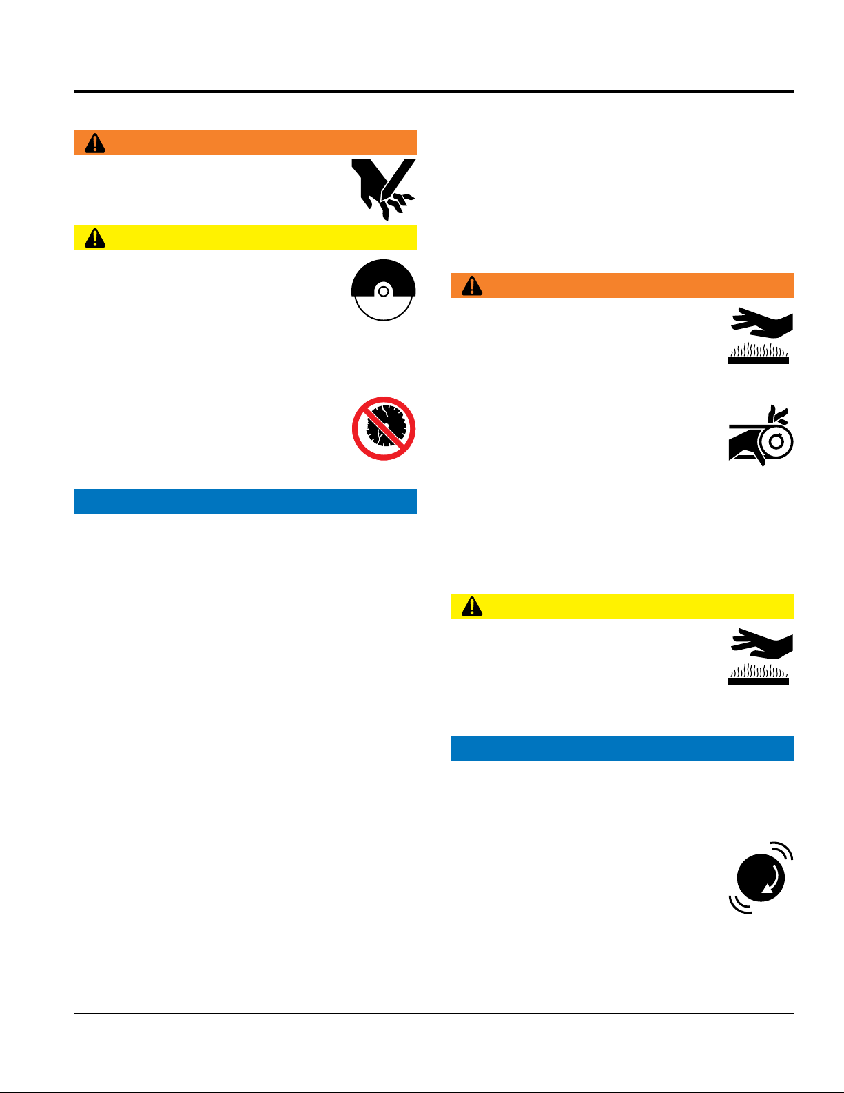
Symbol Safety Hazard
Lethal exhaust gas hazards
Explosive fuel hazards
Burn hazards
Rotating parts hazards
CAUTION
Indicates a hazardous situation which, if not avoided,
COULD result in MINOR or MODERATE INJURY.
NOTICE
Addresses practices not related to personal injury.
Cutting and crushing hazards
Hydraulic fluid hazards
PAGE 8 — SP2S20H PAVEMENT SAW • OPERATION MANUAL — REV. #1 (02/17/12)
Page 9
GENERAL SAFETY
NOTICE
This equipment should only be operated by trained and
Whenever necessary, replace nameplate, operation and
accident due to equipment modifi cations. Unauthorized
recommended by Multiquip for this equipment. Damage
keep
Also, know the phone numbers
fi re department.
SAFETY INFORMATION
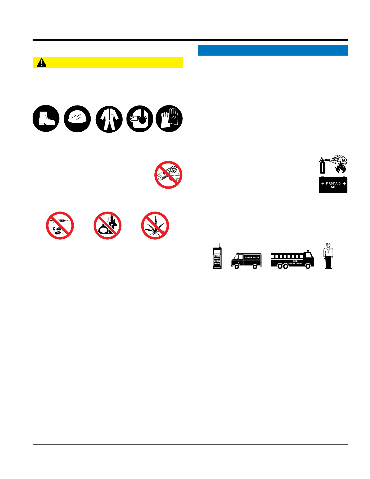
CAUTION
NEVER operate this equipment without proper protective
clothing, shatterproof glasses, respiratory protection,
hearing protection, steel-toed boots and other protective
devices required by the job or city and state regulations.
Avoid wearing jewelry or loose fi tting clothes that may
snag on the controls or moving parts as this can cause
serious injury.
NEVER operate this equipment when not
feeling well due to fatigue, illness or when
under medication.
NEVER operate this equipment under the
infl uence of drugs or alcohol.
ALWAYS clear the work area of any debris, tools, etc.
that would constitute a hazard while the equipment is
in operation.
qualifi ed personnel 18 years of age and older.
safety decals when they become diffi cult read.
Manufacturer does not assume responsibility for any
equipment modifi cation will void all warranties.
NEVER use accessories or attachments that are not
to the equipment and/or injury to user may result.
ALWAYS know the location of the nearest
fi re extinguisher.
ALWAYS know the location of the nearest
fi rst aid kit.
ALWAYS know the location of the nearest phone or
a phone on the job site.
of the nearest ambulance, doctor and
This information will be invaluable in the case of an
emergency.
No one other than the operator is to be in the working
area when the equipment is in operation.
DO NOT use the equipment for any purpose other than
its intended purposes or applications.
SP2S20H PAVEMENT SAW • OPERATION MANUAL — REV. #1 (02/17/12) — PAGE 9
Page 10
SAW SAFETY
NOTICE
placed on appropriate
leaving or when using on a slope. Some saws utilize a
brake system where the brakes are automatically applied
angle of the slope will help prevent accidental downhill
start
use on excessive slopes or on extremely uneven
keep the machine in proper running condition.
Make sure there is no buildup of concrete, grease, oil or
store equipment properly when it is not being
used. Equipment should be stored in a clean, dry location
out of the reach of children and unauthorized personnel.
SAFETY INFORMATION
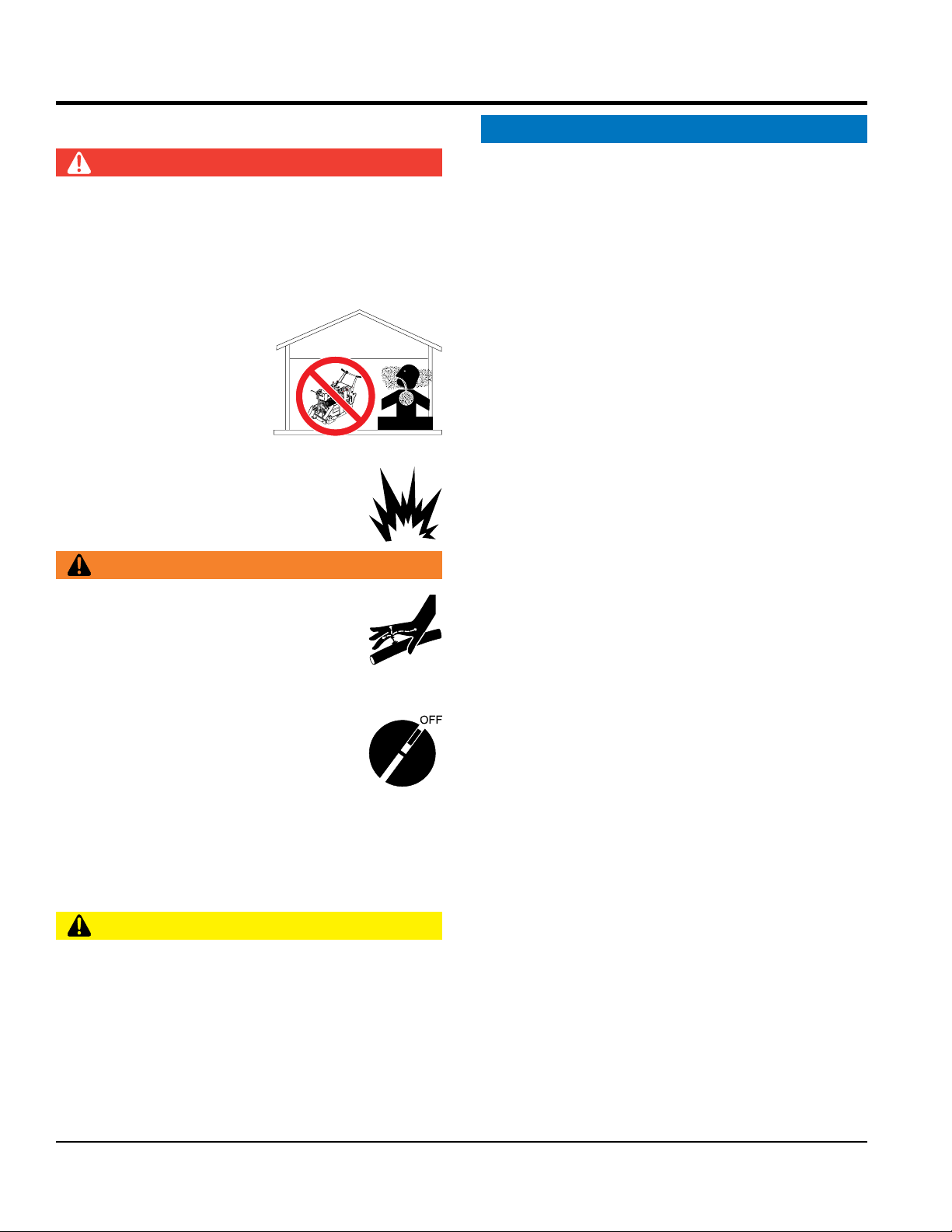
DANGER
Engine fuel exhaust gases contain poisonous carbon
monoxide. This gas is colorless and odorless, and can
cause death if inhaled.
The engine of this equipment requires an adequate free
fl ow of cooling air. NEVER operate this equipment in any
enclosed or narrow area
where free fl ow of the air is
restricted. If the air fl ow is
restricted it will cause injury
to people and property and
serio u s dama g e to t he
equipment or engine.
NEVER operate the equipment in an explosive
atmosphere or near combustible materials. An
explosion or fi re could result causing severe
bodily harm or even death.
WARNING
If applicable, NEVER use your hand to fi nd
hydraulic leaks. Use a piece of wood or
cardboard. Hydraulic fl uid injected into the
skin must be treated by a knowledgeable
physician immediately or severe injury or
death can occur.
Accidental starting can cause severe injury
or death. ALWAYS place the ON/OFF
switch in the OFF position.
NEVER disconnect any emergency or safety devices.
These devices are intended for operator safety.
Disconnection of these devices can cause severe injury,
bodily harm or even death. Disconnection of any of these
devices will void all warranties.
CAUTION
Anytime the saw is lifted onto its nose or tilted fully
back, such as for maintenance access, the high end of
the saw MUST be blocked up to prevent the possibility
of crush injury.
DANGEROUS
GAS FUMES
ALWAYS ensure saw is securely
blocks or jackstands when performing maintenance
requires elevation of the saw.
If saw has brakes, ensure brakes are applied when
when the engine is stopped.
If saw has a parking brake, ensure that the parking
brake is engaged and holds the saw safely in place
when parking on a slope.. Turning the saw across the
movement.
ALWAYS block the saw with appropriate blocks when
leaving the saw parked on a slope.
To prevent unexpected loss of control, DO NOT
engine on a sloping surface
DO NOT
surfaces
ALWAYS start engine with the control handle in
NEUTRAL position to prevent unexpected movement.
ALWAYS
Fix damage to machine and replace any broken parts
immediately.
debris on the machine.
ALWAYS
PAGE 10 — SP2S20H PAVEMENT SAW • OPERATION MANUAL — REV. #1 (02/17/12)
Page 11
BLADE SAFETY
Rotating blade can cut and crush. ALWAYS
D O NOT drop the diamond blade on ground or
Make certain the operator knows how to and is capable
run engine without an air fi lter or with a dirty air
fi lter. Severe engine damage may occur. Service air fi lter
keep hands and feet clear while operating
the saw.
NEVER operate the saw without blade
guards and covers in place. Exposure of
the diamond blade must not exceed 180
degrees.
Verify the engine start switch is set to the OFF position
before installing a blade.
ALWAYS i nspect blade be fo re ea ch
use. The blade should exhibit no cracks,
dings, or fl aws in the steel centered core
and/or rim. Center (arbor) hole must be
undamaged and true.
NOTICE
Use proper blades and follow blade manufacturer’s
recommendations. Match the blade RPM (blade shaft
RPM) to the recommended blade surface feet per minute
(SFPM).
Ensure the blade-mounting bolt is tightened to 125-175
foot lbs. of torque.
ALWAYS examine blade flanges for damage and
excessive wear.
Ensure the blade is marked with an operating speed
greater than the spindle speed of the saw.
Only cut the material that is specifi ed for the diamond
blade. Read the specifi cation of the diamond blade to
ensure the proper tool has been matched to the material
being cut.
WARNING
CAUTION
SAFETY INFORMATION
surface.
Ensure that the blade is mounted for proper operating
direction.
Adhere to the blade manufacturer’s recommendations
on handling, storage and safe usage of blades.
ENGINE SAFETY
WARNING
DO NOT place hands or fingers inside
engi ne compartment when e ngine is
running.
NEVER operate the engine with heat shields or
guards removed.
Keep fi ngers, hands hair and clothing away
from all moving parts to prevent injury.
ALWAYS shut down the engine before
performing service or maintenance.
DO NOT remove the engine oil drain plug while the
engine is hot. Hot oil will gush out of the oil tank and
severely scald any persons in the general area of the
saw.
CAUTION
NEVER touch the hot exhaust manifold,
muffl er or cylinder. Allow these parts to cool
before servicing equipment.
of turning the engine OFF in case of an emergency.
NOTICE
NEVER
frequently to prevent engine malfunction.
If wet cutting, ensure a WET CUTTING blade is being
used and that the water supply system to the blade is
properly functioning and being used.
SP2S20H PAVEMENT SAW • OPERATION MANUAL — REV. #1 (02/17/12) — PAGE 11
NEVER tamper with the factory settings
of the engine or engine governor. Damage
to the engine or equipment can result
if operating in speed ranges above the
maximum allowable.
Page 12
SAFETY INFORMATION
FUEL SAFETY
BATTERY SAFETY (ELECTRIC START ONLY)
drop the battery. There is a possibility that the
keep the battery charged. If the battery is not
charge battery if frozen. Battery can explode.
environment to avoid the risk of a dangerous concentration
NEGATIVE battery terminal
keep battery cables in good working condition.
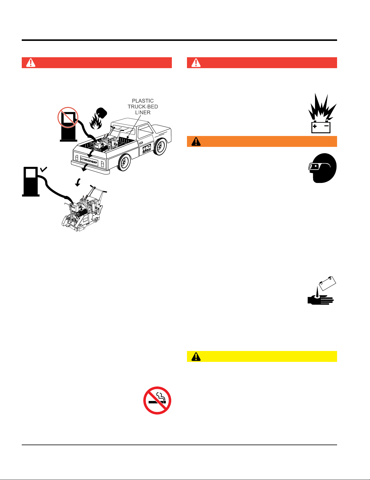
DANGER
DO NOT add fuel to equipment if it is placed inside truck
bed with plastic liner. Possibility exists of explosion or
fi re due to static electricity
FUEL
DO NOT start the engine near spilled fuel or combustible
fl uids. Fuel is extremely fl ammable and its vapors can
cause an explosion if ignited.
FUEL
DANGER
DO NOT
battery will explode.
DO NOT expose the battery to open fl ames,
sparks, cigarettes, etc. The battery contains
combustible gases and liquids. If these
gases and liquids come into contact with a
fl ame or spark, an explosion could occur.
WARNING
A LWAYS wear safety glasses when
handling the battery to avoid eye irritation.
The battery contains acids that can cause
injury to the eyes and skin.
Use well-insulated gloves when picking up
the battery.
ALWAYS
charged, combustible gas will build up.
DO NOT
When frozen, warm the battery to at least 61°F (16°C).
ALWAYS recharge the battery in a well-ventilated
ALWAYS refuel in a well-ventilated area, away from
sparks and open fl ames.
ALWAYS use extreme caution when working with
fl ammable liquids.
DO NOT fi ll the fuel tank while the engine is running
or hot.
DO NOT overfi ll tank, since spilled fuel could ignite if it
comes into contact with hot engine parts or sparks from
the ignition system.
Store fuel in appropriate containers, in well-ventilated
areas and away from sparks and fl ames.
NEVER use fuel as a cleaning agent.
D O NOT smoke around or near the
equipment. Fire or explosion could result
from fuel vapors or if fuel is spilled on a
hot engine.
of combustible gases.
If the battery liquid (dilute sulfuric acid)
comes into contact with clothing or skin,
rinse skin or clothing immediately with
plenty of water.
If the battery liquid (dilute sulfuric acid) comes into
contact with eyes, rinse eyes immediately with plenty
of water and contact the nearest doctor or hospital to
seek medical attention.
CAUTION
ALWAYS disconnect the
before performing service on the equipment.
ALWAYS
Repair or replace all worn cables.
PAGE 12 — SP2S20H PAVEMENT SAW • OPERATION MANUAL — REV. #1 (02/17/12)
Page 13

SAFETY INFORMATION
LIFTING SAFETY
NEVER tip the engine to extreme angles during lifting as
it may cause oil to gravitate into the cylinder head, making
use ramps capable of supporting the weight of
Ensure that the diamond blade does not come into contact
transport the saw to or from the job site with the
CAUTION
NEVER allow any person or animal to stand underneath
the equipment while lifting.
Some saws are very heavy and awkward to move around.
Use proper heavy lifting procedures.
DO NOT attempt to lift the saw by the guards, handle
bars or front pointers.
NOTICE
The easiest way to lift the saw is to utilize the lifting bale. A
strap or chain can be attached to the lifting bale, allowing
a forklift or crane to lift the saw up onto and off of a slab
of concrete. The strap or chain should have a minimum
of 2,000 pounds (1,000 kg) lifting capacity and the lifting
gear must be capable of lifting at least this amount.
Before lifting, make sure that the lifting bale is not
damaged.
Use one point suspension hook and lift straight upwards.
the engine start diffi cult.
Always make sure crane or lifting device has been
properly secured to the lifting bale.
DO NOT lift machine to unnecessary heights.
NEVER lift the equipment while the engine is running.
ALWAYS
the saw and the operator to load and unload the saw.
TRANSPORTING SAFETY
NOTICE
ALWAYS shutdown engine before transporting.
Tighten fuel tank cap securely and close fuel cock to
prevent fuel from spilling.
ALWAYS tie down equipment during transpor t by
securing the equipment with rope.
with the ground or surface during transportation.
LIFTING BALE
NEVER
blade mounted.
SP2S20H PAVEMENT SAW • OPERATION MANUAL — REV. #1 (02/17/12) — PAGE 13
Page 14

SAFETY INFORMATION
ENVIRONMENTAL SAFETY/DECOMMISSIONING
EMISSIONS INFORMATION
This engine has been certifi ed to meet US EPA Evaporative
proper training could damage the equipment or create an
Additionally, modifying the fuel system may adversely affect
evaporative emissions, resulting in fi nes or other penalties.
The emission control label is an integral part of the emission
If a replacement emission label is needed, please contact
NOTICE
Decommissioning is a controlled process used to safely
retire a piece of equipment that is no longer serviceable.
If the equipment poses an unacceptable and unrepairable
safety risk due to wear or damage or is no longer cost
effective to maintain (beyond life-cycle reliability) and is to
be decommissioned (demolition and dismantlement),be
sure to follow rules below.
DO NOT pour waste or oil directly onto the ground, down
a drain or into any water source.
Contact your country's Depar tment of
Public Works or recycling agency in your
area and arrange for proper disposal of
any electrical components, waste or oil
associated with this equipment.
When the life cycle of this equipment is over, remove
batter y and bring to appropriate facility for lead
reclamation. Use safety precautions when handling
batteries that contain sulfuric acid.
When the life cycle of this equipment is over, it is
recommended that the trowel frame and all other metal
parts be sent to a recycling center.
Metal recycling involves the collection of metal from
discarded products and its transformation into raw
materials to use in manufacturing a new product.
Recyclers and manufacturers alike promote the process
of recycling metal. Using a metal recycling center
promotes energy cost savings.
NOTICE
The gasoline engine used in this equipment has been
designed to reduce harmful levels of carbon monoxide
(CO), hydrocarbons (HC) and nitrogen oxides (NOx)
contained in gasoline exhaust emissions.
emissions requirements in the installed confi guration.
Attempting to modify or make adjustments to the engine
emmission system by unauthorized personnel without
unsafe condition.
Emission Control Label
system and is strictly controlled by regulation(s).
The label must remain with the engine for its entire life.
your authorized Honda Engine Distributor.
PAGE 14 — SP2S20H PAVEMENT SAW • OPERATION MANUAL — REV. #1 (02/17/12)
Page 15

Table 1. Specifications (Saw)
SPECIFICATIONS
Blade Capacity
Cutting Depth
Arbor Diameter
Front Wheels
Rear Wheels
125 mm Dia. x 50 mm Wide (5 in. x 2 in.)
203 mm Dia. x 50 mm Wide (8 in. x 2 in.)
Nominal Mass*
Maximum Operating Mass**
lbs. (kg)
Sound Pressure at
Operator’s Position
Hand/Arm Vibration
(At Handle)***
* Nominal Mass: Mass without blade, all fluid tanks empty, any optional parts removed.
** Maximum Operating Mass: Includes blade, all fluid tanks full, any necessary components installed.
*** Hand/Arm Vibration (at handle) results with SP2 Saw cutting cured concrete at a depth of 38.1mm
(1-1/2 in.) with 508 mm (20 in.) blade at FULL THROTTLE.
508 mm (20 in.)
191 mm (7.5 in.)
25.4 mm (1 in.)
173 kg (380 lbs.)
201 kg (443 lbs.)
88.8 dB
5.61 ms
-2
SP2S20H PAVEMENT SAW • OPERATION MANUAL — REV. #1 (02/17/12) — PAGE 15
Page 16

Table 2. Specifications (Engine)
SPECIFICATIONS
Model
Engine Type
Net Power Output
Bore x Stroke
Displacement
Net Torque
Carburetor
Ignition System
Starting System
Lubrication System
Air Cleaner
Oil Capacity
Fuel
Dry Weight
Dimensions
GX630RTXF2
Air-cooled, 4-stroke OHV
20.8 HP (15.5 kW) @ 3,600 rpm
3.1 x 2.8 in (78 x 72 mm)
3
42 in
(688 cm3)
35.6 ft lbs (48.3 Nm) @ 2,500 rpm
Horizontal Type, Two-Barrel Butterfly
Digital CDI with variable ignition
Electric Start
Forced Lubrication
Paper Filter
2.1 US qt (2.0 l)
Unleaded 86 octane or higher
97.88 lb(44.4 kg)
15.94 x 16.14 x 17.24 in
(405 x 410 x 438 mm)
PAGE 16 — SP2S20H PAVEMENT SAW • OPERATION MANUAL — REV. #1 (02/17/12)
Page 17
E
23587
UNLEADED GAS ONLY
H
G
A
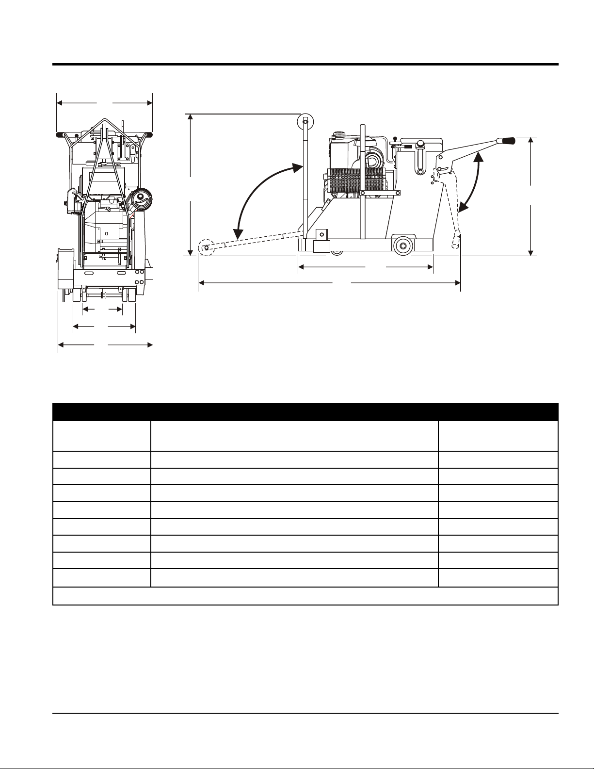
DIMENSIONS
B
C
D
F
REFERENCE
LETTER
A
B
C
D
E
F
G
H
Figure 1. Dimensions
Table 3. Dimensions
DESCRIPTION
Max Height (Handle Bars fully lowered & Front Pointer raised) 914 mm (36 in.)
Max Handle Bar Height (fully raised) 1016 mm (40 in.)
Max Length (Handle Bars & Front Pointer fully raised) 1092 mm (43 in.)
Max Length (Handle Bars fully raised & Front Pointer lowered) 1727 mm (68 in.)
Max Handle Bar Width 610 mm (24 in.)
Max Width 622 mm (24.5 in.)
Rear Wheel Base 406 mm (16 in.)
Front Wheel Base 356 mm (14 in.)
Crated Dimension (L x W x H): 1194 x 762 x 1118 mm (47 x 30 x 44 in.)
DIMENSIONS
IN. (MM)
SP2S20H PAVEMENT SAW • OPERATION MANUAL — REV. #1 (02/17/12) — PAGE 17
Page 18

GENERAL INFORMATION
INTENDED USE
The SP2S20H saw is designed for pavement cutting
utilizing diamond blades. Operation of the saw should be
in accordance with the manufacturer's instructions. The
manufacturer cannot be held liable for damages as a result
of misuse.
FAMILIARIZATION
The saw has been engineered for general and industrial flat
sawing applications. The reinforced steel box frame design
adds strength necessary to reduce blade vibrations while
cutting. By minimizing blade vibrations, the performance
of the blade is enhanced and thus the life of the blade is
extended.
Heavy-duty front and rear axles, sturdy oversized wheels,
and industrial undercarriage assembly ensure accurate
tracking and years of reliable use.
Additionally, the general strength-to-weight ratio design
of the frame and chassis assembly provides for optimum
weight distribution to keep the blade running true in the cut.
A rugged spindle bearing assembly ensures minimal flutter
and shaft harmonics providing the most advantageous
condition for a diamond blade at operating speeds.
The saw comes equipped with a 20-inch blade guard and
is engineered to optimize performance using a 20-inch
diamond blade. Diamond blades ranging from 14", 16" and
18" may be used with reduced overall performance.
A threaded, manual, raise/lower assembly easily raises
and lowers the blade and locks it into position to ensure a
constant depth cut. The saw is equipped with a retractable
cutting guide, oversized roller bearing wheels, industrial
spindle bearings, and a rigid steel frame.
CONSOLE
An ergonomically designed control console allows the
operator to easily understand and/or operate the adjustable
handlebars, the Raise/Lower Crank Handle, and the
transmission engage/disengage lever. Additionally, the
console also provides a forward/reverse control.
POWER PLANTS
The SP2S20H uses a 20HP Honda GX630RTXF2 aircooled, 4-stroke OVH gasoline engine. Blade rotation is
v-belt driven. This is accomplished by connecting to the
output shaft of the engine to an upper drive pulley. The
lower drive pulley (Blade) is then connected to the upper
drive pulley (Engine) by four V-belts. As the engine shaft
rotates, so does the blade.
Refer to the Engine Owner's Manual for specific instructions
regarding engine operation and maintenance practices.
The SP2S20H saw is designed, engineered and
manufactured with strict adherence to American
National Standards Institute, Inc. (ANSI) guidelines
B7.1 and B7.5.
WATER SYSTEM
The SP2S20H saw provides a water plumbing system that
evenly distributes water volume and optimum flow rate to
both sides of the blade to keep it cool when cutting. The
basic water system provides a valve that connects to a
standard garden hose.
The water is delivered (via a standard garden hose) to the
blade guard water plumbing system. When a water source
is not available, a (built-in) removable water tank delivery
system may be used for dust suppression.
FEATURES
Engine Stop Switch conveniently located on handle bar
Super-rigid box frame ensures straight cuts while
resisting warping and blade vibration
Rugged roller bearing wheels for long service life
Comfortable grip handles
Easy cranking for manually raising/lowering the blade to
the desired cutting height
Hinged front, lift-up blade guard is designed to provide
easy blade replacement
Saw position guide helps ensure straight cuts
Main water system provides optimum flow and volume
of water to both sides of the blade
The SP2S20H saw is classified in the industry as a
"medium" powered saw. This classification is particularly
useful when selecting the proper diamond blade for an
application.
PAGE 18 — SP2S20H PAVEMENT SAW • OPERATION MANUAL — REV. #1 (02/17/12)
Manually operated wheel clamps help to prevent
unwanted displacement of saw
Page 19

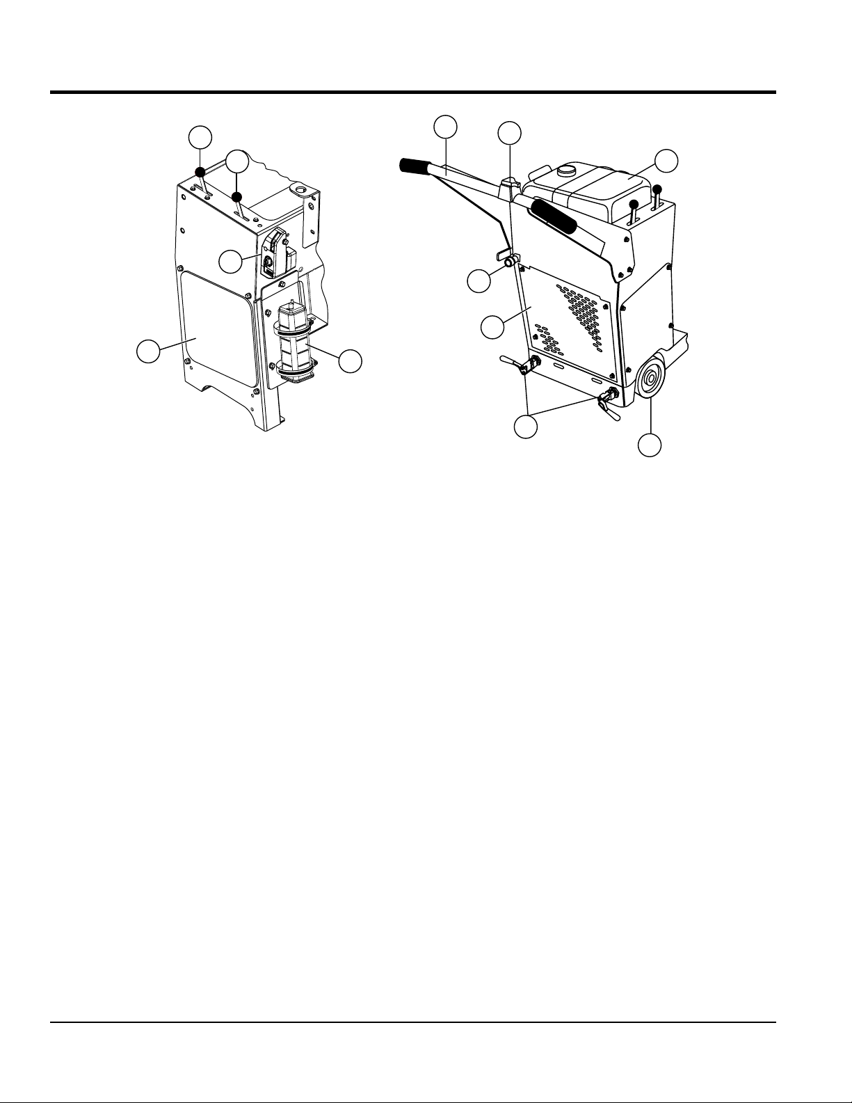
COMPONENTS
10
14
13
12
11
9
8
Figure 2. SP2S20H Components (Left Side)
7
1
4
6
2
3
LEFT-SIDE
5
1. Raise/Lower Crank Handle — Physically orients saw
(raises or lowers) depending on cranking direction
(clockwise or counterclockwise). Turning the handle
clockwise lowers the saw while turning the saw counterclockwise raises the saw.
2. Transmission Engage/Disengage Lever — Forward
locking position engages transmission. Rear Locking
position disengages transmission from rear axle and
permits "free wheeling".
3. Water ON/OFF Valve — ON position opens valve and
permits water to flow from source through saw water
hose. OFF position closes valve and halts the flow of
water.
4. WATER TANK ON/OFF VALVE —Turns on/off the flow
of water from the internal water tank.
5. Blade Removal Tool — Used to remove saw blade
from unit.
6. Belt Cover — Covers the drive shaft belt, engine pulley
and the hydraulic transmission belt.
7. Drive-Shaft Pulley Guard — Covers the drive shaft
pulley.
8. Balance Weight — Helps keep the blade running in
the cut while the saw is traveling through concrete.
9. Saw Blade — Use only MQ recommended blades. This
unit can use 14, 16, 18, and 20-inch blades.
10. Saw Blade Guard — Covers the saw blade during
cutting operations and allows water hoses to be
connected to the cover for wet cutting.
11. Pointer Arm — Front pointer wheel assists in straight
tracking. Lifts up for storage and pivots down for use.
12. Fuel Tank — Holds unleaded gasoline.
13. Lifting Bale — Allows for easy lifting and transporting
of the saw.
14. Choke Knob — Push down to close choke when
operating the saw in cold weather conditions, pull up
to open choke in normal weather.
SP2S20H PAVEMENT SAW • OPERATION MANUAL — REV. #1 (02/17/12) — PAGE 19
Page 20
COMPONENTS
15
16
17
19
18
RIGHT-SIDE
Figure 3. Saw Components (Right Side/ Rear)
15. Forward/Reverse Speed Lever — Controls forward
and reverse speeds. Provides positive neutral for
engine start. ALWAYS place transmission engage/
disengage lever in the engage position before setting
speed lever.
16. Throttle Lever — Used to adjust engine RPM speed
(SLOW or FAST).
17. Ignition Module — Turn switch clockwise to start
engine.
18. Charcoal Canister — A container filled with activated
charcoal that traps gasoline vapors emitted by the fuel
system.
19. Battery Access Panel — Allows access to the battery
for replacement or maintenance.
20. Handle Bars — Used to steer and push the saw during
cutting operations. The handle can be folded down for
transportation.
20
21. Engine OFF Switch — Toggle in either direction to
stop the engine.
22. Water Tank — A 5-gallon (18.95 liters) capacity water
tank provides water for the saw blade during short-run
cutting applications and dust control.
23. Rear Wheels — Allows the saw to be rolled across
ground. The rear wheels are turned by the spline gears
attached to the hydraulic transmission system.
24. Wheel Clamp — Move handle down, making contact
with wheel, to avoid unwanted rolling movement. Lift
handle to release.
25. Access Panel (Hydraulic Drive Transmission) —
Allows access to the hydraulic drive transmission that
controls the saw's forward and reverse movement by
using the forward/reverse speed lever.
26. Water Source Adapter — Connects to the water
source, either to the water tank through a tube or to
a garden hose.
26
25
21
24
REAR
22
23
PAGE 20 — SP2S20H PAVEMENT SAW • OPERATION MANUAL — REV. #1 (02/17/12)
Page 21

BASIC ENGINE
3 4
1 2
8
7
6
5
Figure 4. Engine Components
INITIAL SERVICING
The engine must be checked for proper lubrication and
filled with fuel prior to operation. Refer to the manufacturer's
engine manual for instructions and details of operation and
servicing.
1. Muffler — Used to reduce noise and emissions.
9
10
11
8
12
13
4. Fuel Filler Cap — Remove this cap to add unleaded
gasoline to the fuel tank. Make sure cap is tightened
securely. DO NOT overfill.
5. Fuel Filter — Filters fuel for contaminants.
6. Oil Drain Bolt — Remove to drain crankcase oil.
7. Oil Filter — Spin-on type, filters oil for contaminants.
WARNING
Engine components can generate extreme
heat. To prevent burns, DO NOT touch
these areas while the engine is running or
immediately after operating. NEVER operate
the engine with the muffler removed.
2. Air Cleaner — Prevents dirt and other debris from
entering the fuel system. Unsnap air filter cover to gain
access to filter element.
3. Fuel Tank — Five gallon capacity; use unleaded
gasoline.
DANGER
Add fuel to the tank only when the engine
is stopped and has had an opportunity to
cool down. In the event of a fuel spill, DO
NOT attempt to start the engine until the fuel
residue has been completely wiped up and
the area surrounding the engine is dry.
8. Spark Plug — Provides spark to the ignition system.
Set spark plug gap to 0.028 - 0.031 inch (0.6 - 0.8 mm).
Clean spark plug once a week.
9. Rollover Valve — Prevents the fuel from leaking from
the tank in the event of a rollover.
10. Oil Filler Cap — Remove to add engine oil.
11. Lifting Eye — Provided for use when the removal/
installation of the engine becomes necessary.
12. Oil Dip Stick — Remove to check amount and
condition of oil in crankcase.
13. Starter Solenoid — Starts engine when ignition key
is rotated to the ON position.
SP2S20H PAVEMENT SAW • OPERATION MANUAL — REV. #1 (02/17/12) — PAGE 21
Page 22

INSPECTION
AMBIENT TEMPERATURE
PREPARATION / PRE-INSPECTION
1. Read and fully understand this manual,
the safe ty infor m ati on sec tio n in
particular, and the engine manufacturer's
manual supplied with the saw.
2. Select the correct blade for each application. Refer to
the Blades and Blade Placement sections for further
information.
3. Check blade for wear or damage. Handle
all blades with care and ALWAYS
replace a damaged blade.
4. Clean the saw, removing dirt and dust,
particularly the engine cooling air inlet, carburetor and
air cleaner.
5. Check the air filter for dirt and dust. Replace the air
filter if it is found to be dirty.
6. Check carburetor for external dirt and dust. Clean with
dry compressed air.
the filler neck. Check the oil level shown on the dipstick.
4. If the oil level is low, fill to the edge of the oil filler hole
with the recommended oil type (Table 4). Maximum
oil capacity for the Honda GX630 engine is 2.1quarts
(2.0 liters).
Table 4. Recommended Viscosity Grades
7. Check fastening nuts and bolts for tightness.
8. Ensure a suitable water supply is available, hooked up,
and used (connected via garden hose or with a water
tank supply system).
ENGINE OIL CHECK
1. To check the engine oil level, place the saw on secure
level ground with the engine stopped. The frame
platform must be level to accurately check the engine
oil.
2. Remove the filler dipstick from the engine oil filler hole
(Figure 5) and wipe it clean.
GASOLINE CHECK
1. Remove the gasoline cap located on top of fuel tank.
2. Visually inspect to see if fuel level is low. If fuel is low,
replenish with unleaded fuel.
3. When refueling, be sure to use a strainer for filtration.
DO NOT top-off fuel. Wipe up any spilled fuel.
HYDROSTATIC TRANSMISSION
An EATON® Model 7 hydrostatic transmission (Figure 6)
provides the power for the saw's propulsion system. The
transmission drives a sprocket that directly connects the
spline drive to the rear wheels. The no load forward/reverse
speeds are approximately 24.4 m/min (80 ft/min).
Figure 5. Engine Oil Dipstick
3. Insert and remove the dipstick without screwing it into
PAGE 22 — SP2S20H PAVEMENT SAW • OPERATION MANUAL — REV. #1 (02/17/12)
Figure 6. Hydrostatic Transmission
Page 23

INSPECTION
1. The transmission is factor y filled with approved
hydraulic fluid that has a viscosity equivalent to SAE
20W-20. Should additional servicing be required, the
following hydraulic fluids are recommended:
• General Motors Dextron B
• Ford MM2C-33F
• Ford M2C-41A
• International harvester Hy-Tran Fluids
2. Note the level marks on the reservoir (Figure 7). It is
essential to reference the existing oil conditions (A) cold
or (B) hot prior to operating the saw. DO NOT over fill
the fluid reservoir.
Table 5. Material Listing and Blade Selection
Material Blade
Cured Concrete Cured Concrete Blade
Green Concrete Green Concrete Blade
Asphalt Asphalt Blade
Asphalt over Concrete Asphalt/Concrete Blade
Block, Brick, Masonry,
Refractories
Tile, Ceramic, Stone Tile Blade
Masonry Blade
Figure 7. Transmission Reservoir
NOTICE
Overfilling the transmission with hydraulic fluid may
cause the seals to rupture causing mechanical damage.
BLADE INSPECTION
This saw is to use the following type of blades only:
Steel Core Segmented or Continuous Diamond
Rim Cutting Wheel
Any other type of blade (tool) is not to be used. See Table
5 for specific blade usage for different materials.
Perform the blade inspection as described. Refer to Figure 8
for the location.
Figure 8. Diamond Blade Inspection Points
1. Drive Pin Hole — A commonly located hole on the
diamond blade core that prevents operational blade
slippage between the inner and outer blade flanges
(collars). Inspect the diameter of the hole to ensure
there is no distortion and that a snug fit develops
between the hole and drive pin.
2. Stress Relief Holes (Gullets) — Check the steel core
for cracks that may have propagated from the slots
and/or gullets. Cracks indicate extreme fatigue failure
and if sawing continues, catastrophic failure will occur.
3. Edge Of The Steel Core — Check the diameter
edge for discoloration (blue oxidation) indicating an
overheating condition caused by insufficient cooling
water/air. Overheating of blades may lead to loss of
core tension and increase the possibility for blade
failure. Check to make sure the steel core’s width is
SP2S20H PAVEMENT SAW • OPERATION MANUAL — REV. #1 (02/17/12) — PAGE 23
Page 24

INSPECTION
uniform about the rim of the blade, and not succumbing
to an “under cutting” condition brought about by highly
abrasive material or improper under cutting core
protection.
4. Directional Arrow — Check to ensure that the blade
is oriented properly on the blade shaft for sawing.
Reference the directional arrow in the blade and place
it so the direction of rotation “downcuts” with the turn
of the shaft.
5. Diamond Segment or Rim — Ensure there are no
cracks, dings, or missing portions of the diamond
segment/rim. DO NOT use a blade that is missing
a segment or a portion of the rim. Damaged and/or
missing segments/rims may cause damage to your saw
and injury to the user or others in the operating area.
6. Specifications — Ensure that the blade specifications,
size, and diameter properly match up to the sawing
operation. Wet blades must have water to act as a
coolant. Utilizing a diamond blade not matched properly
to the task may result in poor performance and/or
blade damage.
7. Arbor Hole — It is essential that the arbor hole
diameter properly matches the blade, and that it is free
from distortions. Correct blade flanges (collars) must
be used. The inside face of the flanges must be clean
and free of debris. An out of round arbor condition will
cause damage to the blade and the saw.
8. MAX RPM — This RPM reference is the maximum
safe operating speed for the blade selected. NEVER
exceed the max RPM on the diamond blade. Exceeding
the MAX RPM is dangerous and may cause poor
performance and damage the blade. All blades must
be designed to meet or exceed the maximum spindle
RPM.
CAUTION
Failure to thoroughly inspect the diamond blade for
operational safety could result in damage to the blade
and the saw, and may cause injury to the user or others
in the operating area. All damaged blades must be
discarded.
BLADE SELECTION
Selecting the diamond blade type and grade defines how
the blade will perform both in cutting speed and blade life.
Selection of the proper diamond blade depends on the
following factors:
Material to be Cut
Type of Saw Being Used
Horsepower of Saw
Hardness Characteristics of the Material
Performance Expectations
Factors for sawing economy are:
Type of Blade
Depth of Cut
Sawing Speed
Characteristics of the Material Being Cut
BLADE SPEED
A diamond blade’s performance is directly connected to
specific peripheral (rim) speeds.
The following shaft rotational speeds have been factory set
to ensure optimum blade performance:
SP2S20H - Engine RPM: 3,600
SP2S20H - Blade Shaft RPM: 2,270
20" Diamond Blade SFPM: 11,880
18" Diamond Blade SFPM: 10,692
16" Diamond Blade SFPM: 9,504
14" Diamond Blade SFPM: 8,316
CAUTION
Opera ting s aw blad es at rota tional
speeds greater than those specified
by the manufacturer can cause blade
damage,and may injure the user or others
in the operating area.
PAGE 24 — SP2S20H PAVEMENT SAW • OPERATION MANUAL — REV. #1 (02/17/12)
Page 25

BLADE PLACEMENT
The following steps should be accomplished before placing
the diamond blade on the blade shaft.
1. Set the engine ON/OFF switch to the OFF position.
2. Raise the saw to a high position by cranking the Raise/
Lower handle in a counterclockwise direction.
3. Use the Blade Nut Wrench and Blade Shaft Locking
Wrench stored on the front section of the console to
install the diamond blade.
Refer to Figure 9 when removing or installing the diamond
blade as follows.
1. Blade Guard — Raise the front half of the blade guard
to expose the blade shaft nut and outer flange.
2. Blade Nut Wrench — Remove the blade nut wrench
from the tool holder and unscrew the blade shaft nut
(right-side). This nut loosens clockwise and tightens
counterclockwise.
3. Blade Nut — Remove the blade nut. For reassembly,
DO NOT overtighten the blade nut against the outer
flange. Tighten blade nut approximately 125 - 175 ft-lbs
(169 - 237 N-m).
INSPECTION
Figure 9. Diamond Blade Placement
GUARDS AND COVERS
CAUTION
4. Outside Blade Flange (Collar) — Ensure that the
flange face is clean and free of debris and is placed
flush against the diamond blade. Check that the drive
pin goes through the blade pin hole and seats properly
into the inner flange collar.
5. Blade Pin Hole — Align this hole with the drive pin
hole on the inner flange collar.
6. Diamond Blade — Ensure that the proper blade has
been selected for the job. Pay close attention to the
directional arrow on the blade, clockwise for right-side
cutting and counterclockwise for left-side cutting. The
arbor hole of the blade must match the 1-inch arbor
of the blade shaft.
7. Inner Flange Collar — This flange is fixed upon the
blade shaft and is manufactured with a drive pin hole.
The inside surface of the flange must be free of debris
and must permit a tight closure on the surface of the
blade.
NEVER operate the saw without blade
guards and covers in place. DO NOT
operate with the front of the blade guard
raised. The blade exposure cannot exceed
180 degrees during operations.
Check the following on the blade guard (Figure 10).
Figure 10. Blade Guard
1. Check to ensure the capacity of the blade guard
matches the diameter of your diamond blade.
SP2S20H PAVEMENT SAW • OPERATION MANUAL — REV. #1 (02/17/12) — PAGE 25
Page 26

INSPECTION
2. Check that the guard seats firmly upon the bayonet
fitting of the saw frame.
3. Check that the spring tensioned front cover of the guard
is firmly seated with the rear section of the guard, and
there are no gaps.
4. Check the fit of the water hoses in the sides of the
blade guard. NEVER lift the blade guard while cutting.
5. Check that the flood water tubes are clear and open.
Test the water supply for pressure and flow (to both
sides of the blade) before sawing operations.
Check the following on the blade flange cover (Figure 11):
Figure 11. Blade Flange Cover
V-BELTS ALIGNMENT AND TENSIONING
This saw is equipped with 4 premium V-belts that have
been aligned and tensioned by factory personnel. All V-belts
MUST be installed for proper operation of the saw. Running
the saw with less than the required number of belts may
damage the saw or equipment.
Perform the following to check the alignment of V-belts:
1. Remove the bolts that secure the V-belt cover
(Figure 12) to the saw frame.
6. Check that the flange cover seats firmly upon the
bayonet fitting of the saw frame prior to operation.
7. This flange cover is to be in place when cutting from
either the right or left side of the saw.
Figure 12. V-Belt Cover Removal
2. Check uniform parallelism (Figure 13) of V-belts and
pulley (sheaves). Use a straight edge or machinists's
square against both pulleys and adjust both pulleys
until equally aligned.
Figure 13. V-Belt Parallelism
PAGE 26 — SP2S20H PAVEMENT SAW • OPERATION MANUAL — REV. #1 (02/17/12)
Page 27

INSPECTION
3. Check V-belt tension (Figure 14) by using a tensionmeter
(2.7 - 4.1 kg/6.0 - 9.0 lbs.) against the inside belt at a
midpoint between the two pulleys, or by deflecting the
center belt at a midpoint 10 mm (3/8”) - 13 mm (1/2”).
CORRECT V-BELT
TENSION 3/8 IN. (10 MM) TO
1/2 IN.(13 MM) WHEN
DEPRESSED AT MIDPOINT
AS SHOWN
Figure 14. V-Belt Tension
NOTICE
WATER TANK
This saw is equipped with a removable 19-liter (5-gallon)
on-board water tank fitted in the top of the console which
can be connected to the brass hose fitting on the rear of
the operator's console (Figure 18).
DO NOT over-tension or under-tension the V-belts.
Severe damage can occur to the saw and engine crank
shaft if the belts are over-tensioned. A decrease of
power to the blade and poor performance will result if
the belts are under-tensioned (loose on pulleys).
4. If the V-belts becomes worn or loose, replace them by
using the V-belt part numbers listed in Table 6.
Table 6. V-Belts and Pulleys
Blade
Size
508mm
(20 in)
V-Belt P/N
(Qty)
15897 (4) 28833-002 23280-001
Engine
Pulley P/N
Blade Shaft
Pulley P/N
Figure 15. Water Tank
Before using the water tank, ensure it is filled to capacity
and connected to the hose fitting to provide lubrication
during cutting. An external water source can also be
connected to the saw for extended wet cutting operations.
HANDLE BAR ADJUSTMENT
This saw has adjustable height handle bars. Before
operating the saw, adjust the handle bar height to a
comfortable working position:
1. Loosen the height adjustment bolts (Figure 16) on the
handle bars until the handle bars can freely pivot.
Figure 16. Handle Bar Adjustment Bolt
SP2S20H PAVEMENT SAW • OPERATION MANUAL — REV. #1 (02/17/12) — PAGE 27
Page 28
INSPECTION
2. Move the handle bars (Figure 17) up or down to
operator's desired preference.
Figure 17. Handle Bar Height Adjustment
3. Tighten the height adjustment bolts to secure the
handle bars in place.
CAUTION
To avoid losing control of the saw, be sure to fully tighten
the adjustment bolts before operation to prevent the
bolts from loosening during cutting.
DETERMINING THE CUT DEPTH
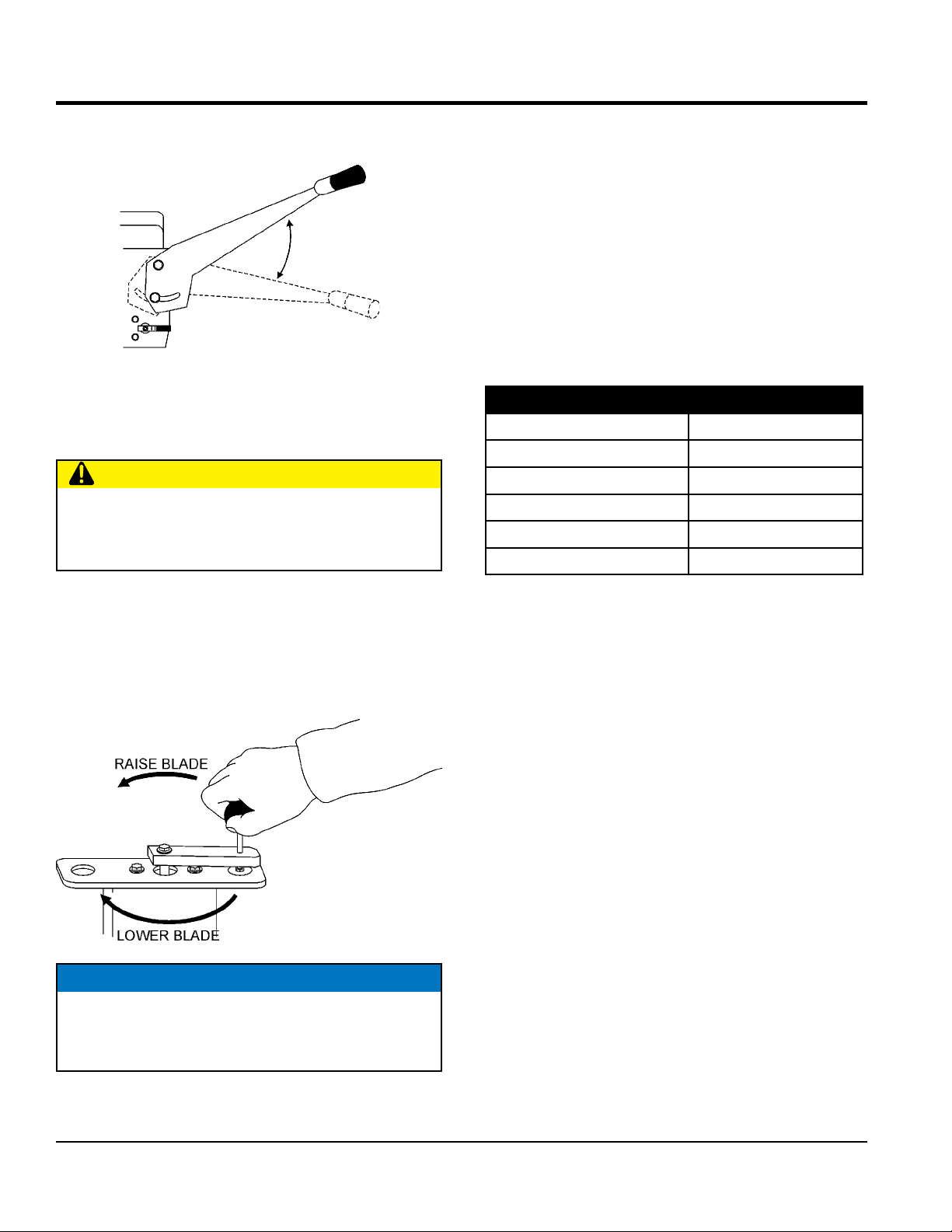
To adjust the blade height:
1. Pull upward on the raise/lower crank handle knob.
2. Rotate the crank handle clockwise to lower the blade.
Rotate the crank handle counterclockwise to raise the
blade (Figure 18). The handle will stop rotating when
the blade has been fully raised or lowered.
When preparing to cut, your blade size determines the
depth of the cut. See Table 7 to determine the proper blade
size for your required cutting depth.
Table 7. Blade Size Selection
Diamond Blade Diameter Depth of Cut
304.8 mm (12 in.) 92.1 mm (3-5/8 in.)
355.6 mm (14 in.) 117.48 mm (4-5/8 in.)
406.4 mm (16 in.) 142.88 mm (5-5/8 in.)
457.2 mm (18 in.) 168.28 mm (6-5/8 in.)
508 mm (20 in.) 193.68 mm (7-5/8 in.)
BLADE HEIGHT ADJUSTMENT
This saw uses a manual raise/lower crank handle located
on the console with clockwise rotation providing lowering
action, and counterclockwise rotation providing raising and
lowering action (Figure 18).
Figure 18. Blade Height Adjustment
NOTICE
When moving the saw around between cutting, fully
raise the blade to avoid striking the ground with the
blade.
PAGE 28 — SP2S20H PAVEMENT SAW • OPERATION MANUAL — REV. #1 (02/17/12)
Page 29

STARTUP
ENGINE STARTUP
1. Ensure the wheel clamps are in the LOCKED position.
(Figure 19).
Figure 19. Wheel Clamp
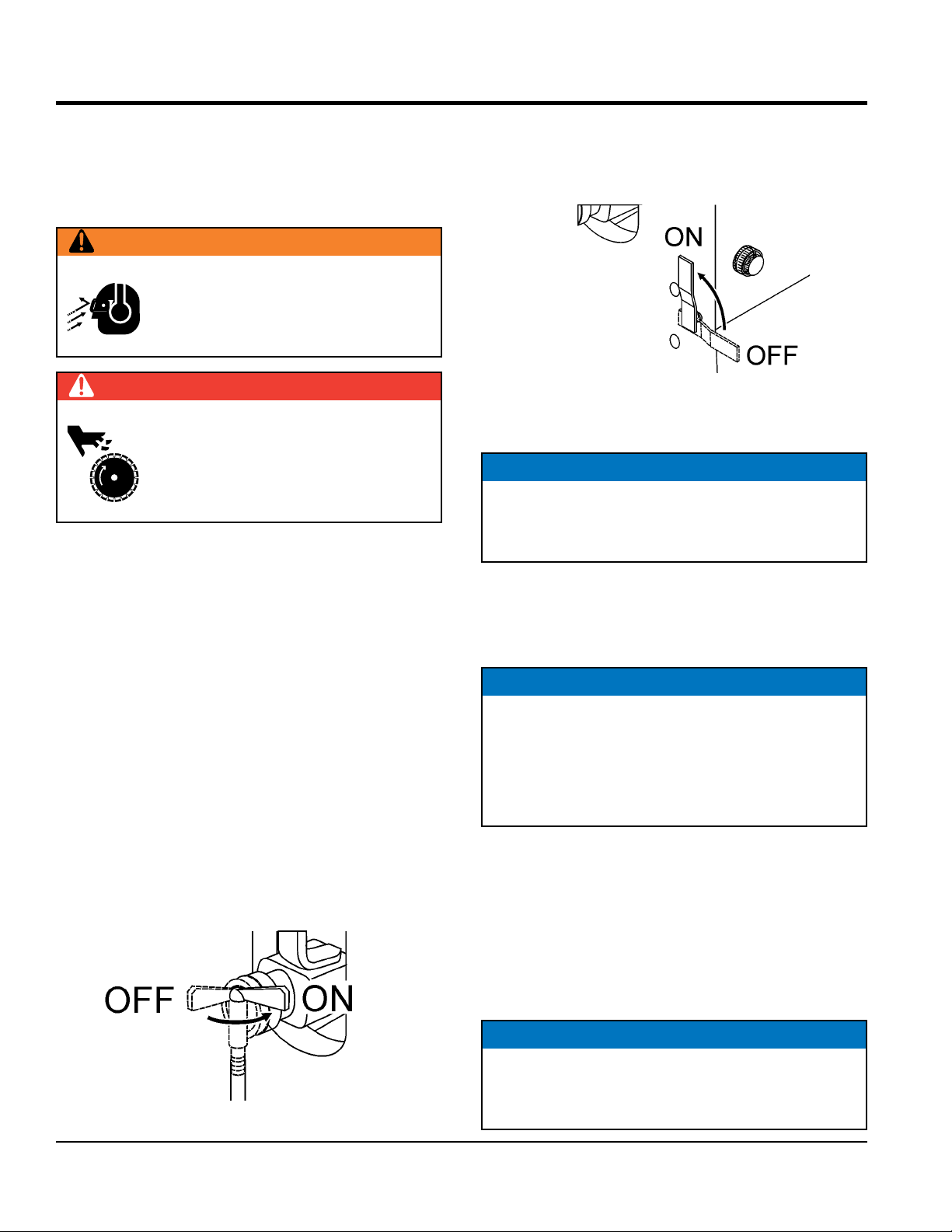
2. Ensure the Engine Shutdown Switch on the handlebar
and the ignition switch are both in the OFF position to
avoid accidental starting (Figure 20 and Figure 21).
4. If operating the saw in cold weather conditions, place
the Choke Lever (Figure 22) in the CLOSED position.
PUSH
(CLOSE)
Figure 22. Choke Lever (Closed Position)
5. In normal weather conditions, place the choke lever in
the OPEN position (Figure 23).
PULL
(OPEN)
Figure 20. Engine Shutdown Switch
Figure 21. Ignition Switch (OFF position)
3. Ensure the diamond blade has been mounted correctly
and that it is raised above the surface you are about
to saw.
NOTICE
The CLOSED position of the choke lever enriches the
fuel mixture for starting a COLD engine. The OPEN
position provides the correct fuel mixture for normal
operation after starting, and for restarting a warm
engine..
Figure 23. Choke Lever (OPEN Position)
6. Place the throttle lever (Figure 24) halfway between
fast and slow for starting.
FAST
SLOW
Figure 24. Throttle Lever (Mid Position)
7. Rotate the engine shutdown switch (Figure 20) to the
ON position.
SP2S20H PAVEMENT SAW • OPERATION MANUAL — REV. #1 (02/17/12) — PAGE 29
Page 30

STARTUP
8. Rotate the ignition switch to the START position to
engage the starter.
Figure 25. Ignition Switch (START) position
9. Once the engine has started, slowly return the choke
lever (Figure 22) to the CLOSED position. If the engine
has not started repeat steps 4 through 8.
10. Before the saw is placed into operation, place the
throttle lever in the FAST position and run the engine
for several minutes. Check for fuel leaks and noises
associated with a loose guard and/or covers.
CAUTION
ALWAYS cut with the saw at FULL THROTTLE.
Attempting to cut with the saw at less than full throttle
could cause the blade to bind or stop abruptly in the
slab resulting in serious injury to the operator or others
in the area.
CAUTION
DO NOT try to cut faster than the blade will allow.
Cutting too fast will cause the blade to rise up out of
the cut. Improper cutting rate can decrease the life of
the engine and blades.
Figure 26. Throttle Lever (FAST Position)
NOTICE
All cutting is done at full throttle. The engine governor
has been set at the factory to ensure an optimum
speed setting.
PAGE 30 — SP2S20H PAVEMENT SAW • OPERATION MANUAL — REV. #1 (02/17/12)
Page 31

OPERATION
TRAVELING DURING CUTTING
This saw has a hydrostatic transmission which mechanically
propels the saw during cutting operations. To prepare the
machine:
1. Place the travel lever in the neutral position (Figure 27).
Figure 27. Travel Lever (Neutral Position)
2. Lift the transmission engage/disengage lever, located
on the console (Figure 28) to engage. Leaving the
lever down disengages the transmission to allow for
manual pushing during cutting or moving the machine
around the job site.
3. Move the travel lever towards the FORWARD position
to increase forward travel speed during cutting
(Figure 29). Placing the travel lever fully forward will
move the saw at maximum speed.
Figure 29. Travel Lever (Forward Position)
4. When reverse movement is required, move the travel
lever towards the REVERSE position (Figure 30).
Placing the travel lever fully in reverse will move the
saw backwards at its maximum reverse speed.
Figure 28. Transmission Engage/Disengage
Lever (Engaged Position)
Figure 30. Travel Lever (Reverse Position)
SAW ALIGNMENT
1. The saw employs a front pointer (Figure 31) that
has been precisely aligned with the diamond blade
at the factory. Accurate tracking is accomplished by
referencing the front pointer tip over the cut line. Precise
saw direction is accomplished by slight operator
pressure against the handle bars.
FRONT
POINTER
Figure 31. Saw Pointer
SP2S20H PAVEMENT SAW • OPERATION MANUAL — REV. #1 (02/17/12) — PAGE 31
Page 32
OPERATION
2. To reorient a pointer position, loosen the screw
that secures the pointer bar to the shaft, adjust as
necessary, and retighten the screw.
CUTTING
WARNING
The operator must wear the appropriate
protective equipment and clothing while
engaged in sawing. Failure to do so can result
in SERIOUS INJURY.
DANGER
DO NOT operate this machine without the
Blade Guard or V-belt Guards in place. While
the blade is spinning, DO NOT place hands,
feet, or other body parts near the blade to
avoid SERIOUS INJURY or DEATH.
1. When cutting, determine the required cutting depth
and use an appropriately sized blade. Deep sawing is
wasteful to the life of the blade.
2. The preferred method of sawing is to step cut in
increments of 51 mm (2 inches). Step cutting provides
the optimum opportunity for the blade to cut fast and
last longest.
WATER SYSTEM
1. Connect hose from water source (on-board water tank
or external water source) to the hose fitting connection
(Figure 3) of the saw. The source pressure should be
approximately 30-40 psi.
4. Open the water system valve on the left side of the
console by moving the lever to the ON position (Figure
33) and ensure the water is flowing equally to both
sides of the diamond blade.
Figure 33. Water System ON/OFF Valve
5. Align the saw along the cut line utilizing the front pointer.
NOTICE
ALWAYS saw in a straight line only. Serious damage
to the blade or saw may occur if the saw is twisted or
forced to cut radius shapes
6. Slowly lower the diamond blade onto the cut line by
cranking the Raise/Lower handle clockwise. When the
handle can no longer be turned, the blade will be at
its full rated depth.
NOTICE
If the water supply to your blade is interrupted, STOP
cutting immediately to prevent damage to your blade
and/or saw.
If the engine stalls for any reason during cutting, raise
the blade out of the cut before restarting.
2. Ensure the vinyl water tubes are properly inserted into
the blade guard holes and are clear of any obstructions.
3. Turn water source on (Figure 32).
Figure 32. On-board Water Tank ON/OFF Valve
PAGE 32 — SP2S20H PAVEMENT SAW • OPERATION MANUAL — REV. #1 (02/17/12)
7. Follow steps 1 to 4 of the Traveling During Cutting
section.
8. The rotation of the blade creates a tendency for the
saw to slightly pull in a particular direction. To ensure
a straight line of sawing, apply pressure against the
appropriate side of the handle bar as you slowly
advance the saw forward.
NOTICE
ALWAYS saw in a straight line only. Serious damage
to the blade or saw may occur if the saw is twisted or
forced to cut radius shapes
Page 33

OPERATION
FINISHING A CUT
1. Raise the blade out of the cut by cranking the Raise/
Lower handle counterclockwise. Raise the blade high
enough out of the cut to clear the surface and allow
the saw to be maneuvered.
2. Shut the engine down according to the SHUTDOWN
PROCEDURE.
RESTARTING AFTER INTERVENTION
If cutting is interrupted where the engine stops or is turned
off while the blade is still in the cut:
1. Turn engine Shutdown switch on handlebar to the
OFF position.
2. Raise the blade out of the cut
3. Restart the engine as described in the STARTUP
section.
NOTICE
SHUTDOWN PROCEDURE
Stopping the engine under normal conditions:
1. Disengage the drive by placing the forward/reverse
speed lever (Figure 34) in the NEUTRAL position.
Figure 34. Speed Lever (Neutral Position)
2. Place the engine throttle lever (Figure 35) in the slow
position, and listen for the engine speed to decrease.
Allow engine to run for 2 or 3 minutes for proper
cooldown.
The only acceptable method for freeing a stuck blade
is to remove the saw from the stuck or pinched blade.
DO NOT try to get the blade unstuck using the Raise/
Lower system or by lifting the saw by the lifting bale, etc.
If cutting is interrupted where the blade is stuck in the cut:
1. Turn Engine On/Off switches to OFF.
2. Remove the blade guard.
3. Maneuver the saw away from the stuck blade.
4. A parallel cut made next to the blade may be necessary
to free it.
5. Once the blade is free, inspect the blade for damage.
Discard blade, if damaged.
6. Ensure an undamaged, usable blade is installed on
the saw before cutting is resumed.
Figure 35. Throttle Lever (Slow Position)
3. Turn the Engine Shutdown Switch located on the
handlebars to the OFF position. Shutting the engine off
using this switch confirms that is functioning properly.
4. Turn the ignition switch (Figure 36) to the OFF position.
The ignition switch must be turned off to prevent
unwanted battery discharge.
Figure 36. Ignition Switch (OFF Position)
5. Place the fuel valve lever (Figure 48) to the OFF
position.
SP2S20H PAVEMENT SAW • OPERATION MANUAL — REV. #1 (02/17/12) — PAGE 33
Page 34

Table 8. Engine Maintenance Schedule
MAINTENANCE
EVERY
YEAR
OR 300
HRS.
DESCRIPTION
(3)
OPERATION
BEFORE
EACH
USE
FIRST
MONTH OR
20 HRS.
EVERY 6
MONTHS
OR 100
HRS.
Check X
Engine Oil
Change X X
Engine Oil Filter Replace Every 200 Hrs.
Check X
Air Cleaner
Clean X (1)
Change X (*)
Check/Adjust X
Spark Plugs
Replace X
Spark Arrester Clean X
Fuel Filter Replace X (2)
Fuel Tube Check Every 2 years (replace if necessary) (2)
* - Replace the paper filter element only.
(1) Service more frequently when used in DUSTY areas.
EVERY 2
YEARS OR
500 HRS.
(2) These items should be serviced by your service dealer, unless you have the proper tools and are mechanically proficient.
Refer to the HONDA Shop Manual for service procedures.
(3) For commercial use, log hours of operation to determine proper maintenance intervals.
Table 9. Saw Maintenance Schedule
Periodic Maintenance
Interval
Check Item OPERATION DAILY
Every
25 Hrs
Every
50 Hrs
Every
100
Hrs
Bearing Lubrication (Rear Wheels) Grease X
Bearing Lubrication (Blade Shaft) Grease X
Raise/Lower Adjust Tube Grease X
Transmission Reservoir Cup Check X
Drive Chain Check X
Spline Gear Wheels Check X
PAGE 34 — SP2S20H PAVEMENT SAW • OPERATION MANUAL — REV. #1 (02/17/12)
Page 35

MAINTENANCE
Ge neral m aintenance pract ices are crucial to the
performance and longevity of your saw. The extreme
environments of sawing operations require routine cleaning,
lubrication, belt tensioning, and inspection for wear and
damage.
The following procedures, devoted to maintenance, can
prevent serious saw damage or malfunctioning.
CAUTION
Before servicing or inspection, ALWAYS park the saw
on a level surface with the blade removed. The Console
Engine ON/OFF switch and Engine ON/OFF switch
should be in the OFF position.
WARNING
Some maintenance operations may
require the engine to be run. Ensure
that the maintenance area is well
ventilated. Exhaust contains poisonous
carbon monoxide gas that can cause
unconsciousness and may result in
DEATH
AIR CLEANER
This engine is equipped with a replaceable, high-density
paper air cleaner element. See Figure 37 for air cleaner
components.
ARROW
MARK
(CASE)
MAIN
ELEMENT
AIR CLEANER
CASE
LATCH
Figure 37. Air Cleaner Components
ARROW
MARK
(DUST PAN)
DUST
PAN
EVACUATOR
VALVE
CAUTION
ALWAYS allo w the engin e to co o l
before servicing. NEVER attempt any
maintenance work on a hot engine.
CAUTION
ALWAYS make sure that the spindle has
COMPLETELY STOPPED ROTATING
before serv icing blades and eng ine
components.
GENERAL CLEANLINESS
Clean the machine daily. Remove all dust and slurry buildup.
If the saw is steam-cleaned, ensure that lubrication is
accomplished AFTER steam cleaning.
ENGINE CHECK
Check daily for any oil and/or fuel leakage, thread nut and
bolt tightness, and overall cleanliness.
1. Check the air cleaner daily or before starting the engine.
2. Check for and correct heavy buildup of dirt and debris
along with loose or damaged components.
3. Replace the element if it is found to be damaged,
excessively dirty, or oily.
NOTICE
Operating the engine with loose or damaged air cleaner
components could allow unfiltered air into the engine
causing premature wear and failure.
Cleaning the Air Cleaner
CAUTION
Wear prot ective equ ipment such as
approved safety glasses or face shields
and dust masks or respirators when
cleaning air filters with compressed air.
The air cleaner should be cleaned every 6 months. To
service the air cleaner perform the following steps. See
Figure 37 for location of parts.
SP2S20H PAVEMENT SAW • OPERATION MANUAL — REV. #1 (02/17/12) — PAGE 35
Page 36

4. Release the latches located on either side of the air
SEAL
cleaner dust pan. Remove the dust pan.
5. Remove the air cleaner element.
6. Blow low pressure air from the inside of the element
to dislodge the dust and dirt. Do not use excessive air
pressure or the element will be damaged and will need
to be replaced.
MAINTENANCE
7. Replace the element if it is damaged or excessively
dirty.
8. Clean the inside of the dust pan.
9. Reinstall the element or if equipped, the precleaner
over the paper air cleaner element.
10. Reinstall the air cleaner dust pan and secure the
latches.
NOTICE
DO NOT run the engine with the air cleaner removed
or without an element.
ENGINE OIL INSPECTION
Check daily. Inspect with blade removed and saw frame
on a level surface. Keep the oil clean and at the proper
servicing level. SAE 10W-30 of SG is recommended for
general use. DO NOT OVERFILL!
ENGINE OIL CHANGE
SEAL
WASHER
DRAIN
BOLT
(REMOVE)
Figure 38. Draining the Engine Oil
ENGINE OIL FILTER CHANGE
1. Replace the engine oil filter (Figure 39) every 200 hours.
OIL
FILTER
Change engine oil the first month or 20 hours of operation,
then every 6 months or 100 hours of operation.
1. Drain the engine oil when the oil is warm as shown in
Figure 38.
2. Remove the oil drain bolt and sealing washer and allow
the oil to drain into a suitable container.
3. Replace engine oil with recommended type oil as
listed in Table 4. For engine oil capacity, see Table 2.
DO NOT overfill.
4. Install drain bolt with sealing washer and tighten
securely.
PAGE 36 — SP2S20H PAVEMENT SAW • OPERATION MANUAL — REV. #1 (02/17/12)
Figure 39. Oil Filter
2. Be sure to coat the seal of the new oil filter with clean
engine oil.
FUEL FILTER CHANGE
1. Replace the engine fuel filter (Figure 40) every year or
300 hours.
Figure 40. Fuel Filter
Page 37

MAINTENANCE
IN.
)
SPARK PLUG ADJUSTMENT
NOTICE
For good performance, the spark plugs must be
properly gapped and free of deposits.
While a loose spark plug can overheat or damage the
engine, overtightening the sparkplug can damage the
threads in the cylinder head.
1. Make sure the engine is cool before servicing the
spark plugs.
2. Disconnect the spark plug caps. Check for dirt and
remove any dirt from around the spark plug area.
3. Remove the spark plugs with a 5/8-inch spark plug
wrench.
4. If the spark plugs are damaged, the sealing washer is
in poor condition, or if the electrode is worn, replace
the spark plugs.
5. Measure the spark plug electrode gaps with a wire-type
feeler gauge. If needed, adjust the gap to 0.7 - 0.8
mm (0.028 - 0.031 in), by carefully bending the side
electrode. See Figure 41.
SPARK ARRESTER CLEANING
Clean the spark arrester every 6 months or 100 hours.
1. Remove the special screw from the muffler and remove
the spark arrester (Figure 42).
Figure 42. Removing Spark Arrester
2. Carefully remove carbon deposits from the spark
arrester screen with a brush (Figure 43).
GAP
.028 - .031
(0.7- 0.8 MM.
Figure 41. Spark Plug Gap Adjustment
6. Install the spark plug carefully, by hand, to avoid cross
threading.
7. After the spark plug is seated, tighten with a 5/8-inch
spark plug wrench to compress the sealing washer.
8. When installing a new spark plug, tighten 1/2 turn, after
the spark plug seats, to compress the washer.
9. When reinstalling the original spark plug, tighten 1/8 1/4
turn after the spark plug seats to compress the washer.
10. Reattach the spark plug caps.
Figure 43. Cleaning The Spark Arrester
3. If the spark arrester is damaged and has breaks or
holes, replace with a new one.
4. Reinstall the spark arrester and muffler protector.
SP2S20H PAVEMENT SAW • OPERATION MANUAL — REV. #1 (02/17/12) — PAGE 37
Page 38

MAINTENANCE
BEARING LUBRICATION
There are four grease points for the saw. Use only Premium
Extreme Pressure Grease, conforming to NLG1 Grade #2
consistency, to grease the zerk fittings.
1. Rear Wheels (1) — Grease daily (Figure 44).
ZERK
GREASE
FITTING
Figure 44. Rear Wheels
2. Blade Shaft Bearings (2) — Grease daily (Figure 45).
GENERAL TRANSMISSION CARE
The saw utilizes spline gear wheel design coupled with an
EATON Model 7 Hydrostatic Transmission that provides
forward/reverse propulsion. The simple design of the
system keeps maintenance to a minimum.
Transmission Reservoir Cup
Check every 8 hours of operation. When the transmission
is cold (A), check oil level against the level indicator.
NOTICE
DO NOT use multiple viscosity oil. DO NOT overfill.
PILLOW
BLOCK
BEARING
ZERK
GREASE
FITTING
Figure 45. Blade Shaft Bearings
3. Raise/Lower Adjust Tube (1) — Grease daily (Figure
46).
ZERK
GREASE
FITTING
Figure 47. Transmission Reservoir
Servicing:
The transmission reservoir is factor y-filled. Should
servicing be required, use SAE20W-20, API classification
(SE,CC,CD) or better, General Motors Dexron B, Ford
M2C-33F, M2C-41A or International Harvester Hy-Tran
fluids. For extreme hot weather, drain oil and refill with an
oil having a viscosity of SAE30W-30 or SAE40W-40.
Drive Chain:
Check every 50 hours. Periodically wipe the chain clean
and relubricate with penetrating chain oil.
The drive chain may stretch requiring tension adjustments.
To adjust the drive chain tension perform the following
steps. Refer to Figure 48 for location of parts.
1. Loosen the four transmission attachment screws.
Figure 46. Raise/Lower Adjust Tube
PAGE 38 — SP2S20H PAVEMENT SAW • OPERATION MANUAL — REV. #1 (02/17/12)
2. Pivot the transmission in the “U” slots of the transmission
mount until the proper tension is achieved.
Page 39
MAINTENANCE
NOTICE
Excessive tension on the drive chain will reduce chain
life.
LOOSEN
SCREWS
4 PLACES
U-SLOTS
TRANSMISSION
MOUNT
HYDROSTATIC
TRANSMISSION
Figure 48. Hydrostatic Transmission
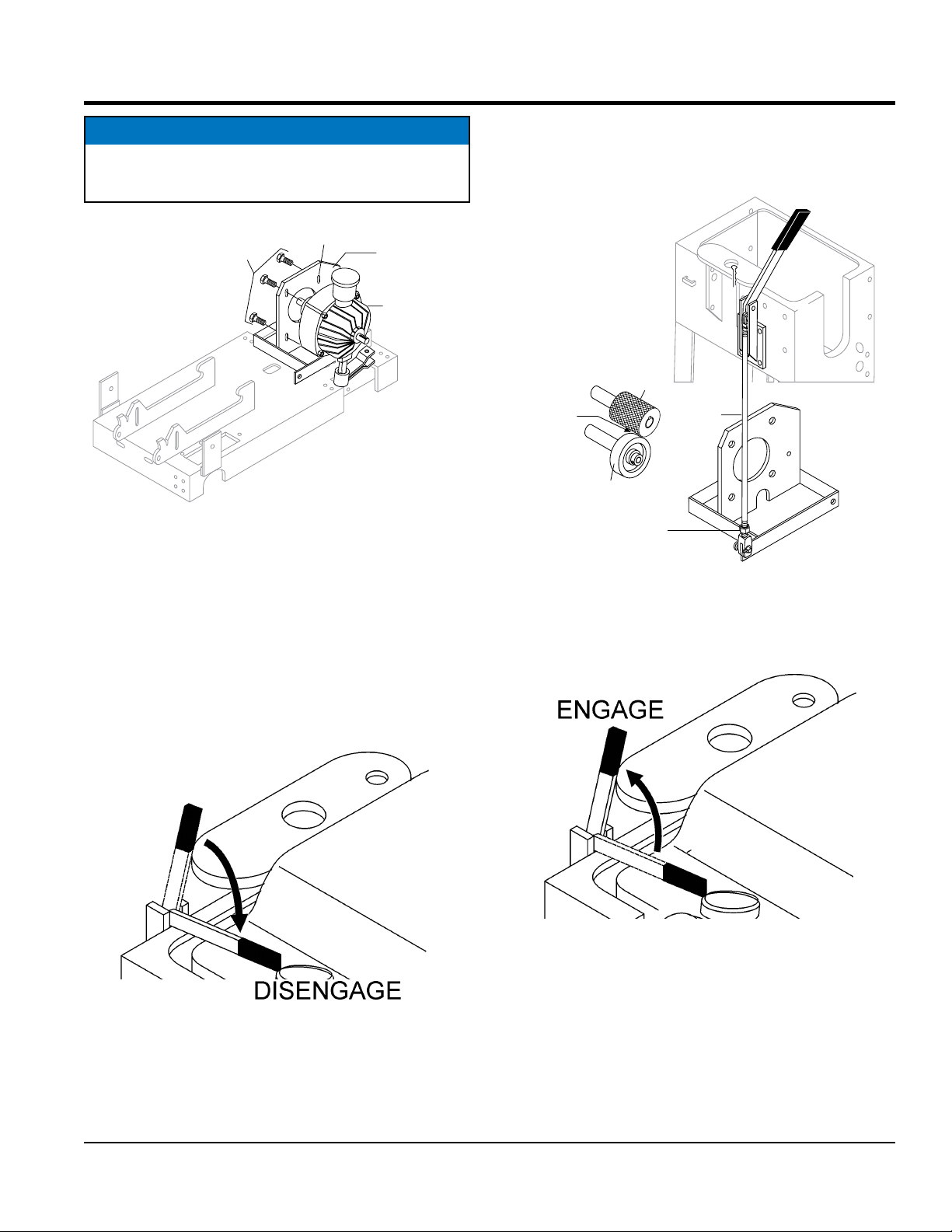
Spline Gear Wheels
Check every 25 hours and clean as necessary. If the spline
wheels DO NOT engage the rear wheels with sufficient
pressure, slippage of the rear wheels may occur.
To adjust the Spline Gear Assembly:
2. Loosen the linkage adjustment nut and slightly lengthen
the linkage rod (Figure 50).
TRANSMISSION
ENGAGE/DISENGAGE
LEVER
SPLINE
GEAR
CONTACT
POINT
REAR WHEEL
ADJUSTMENT
JAM NUT
LINKAGE
ROD
Figure 50. Linkage Adjustment
3. Move the transmission engage/disengage lever to the
ENGAGE position to observe the proper spline-to-rear
wheel contact (Figure 51).
1. Place the transmission engage/disengage lever in the
DISENGAGE position (Figure 49).
Figure 49. Transmission Lever
(Disengaged Position)
SP2S20H PAVEMENT SAW • OPERATION MANUAL — REV. #1 (02/17/12) — PAGE 39
Figure 51. Transmission Lever
(Engaged Position)
4. Retighten the adjustment nut.
Page 40

6 PLACES
MAINTENANCE
DRIVE V-BELT CHECK
The V-Belts of the saw have been factory-set utilizing
precision standards. Operating the saw with less than the
specified number of V-belts (See Table 6), or belts that are
slipping or are over-tensioned, will significantly diminish
the performance of the saw and may cause damage to
the blade.
V-Belt Replacement and Tension Adjustment
1. Remove the Belt Guard (Figure 52).
BELT GUARD
(REMOVE)
REMOVE
SCREWS
3. Loosen the four 1-1/2” HHC screws from the engine
mount (Figure 54).
ENGINE
BASE
ENGINE
BASE
PIVOTS
LOOSEN
SCREWS
LOOSEN
ENGINE MOUNT
CARRIAGE BOLT
4 PLACES
Figure 54. V-belt Adjustment
4. Loosen and back-off the engine mount carriage bolt
from the frame to permit the engine base to pivot.
5. Pivot the engine base to adjust the belt to the correct
tension (Figure 53).
Figure 52. Belt Guard Removal
2. Check the V-belt tension (Figure 53). If the V-belt
tension is correct, reinstall belt guard. If V-belt needs
adjustment or replacement, continue to the next steps.
CORRECT V-BELT
TENSION 3/8 IN. (10 MM) TO
1/2 IN.(13 MM) WHEN
DEPRESSED AT MIDPOINT
AS SHOWN
Figure 53. V-Belt Tension Check
6. If V-belt needs to be replaced, pivot the engine base
to provide slack in the V-belt. Remove the V-belt and
replace with new one (See Table 6). Pivot the engine
base to adjust the belt to the correct tension.
7. Rotate the engine back into place and tighten the
Engine Mount Carriage Bolt.
8. Retighten the four 1-1/2” HHC screws.
9. Replace all guards and covers.
WARNING
CLUTCH
PULLEY
NEVER attempt to check the V-belt
with the engine running. Severe injury
can occur if your hand gets caught
between the V-belt and the clutch.
VIBRATOR
PULLEY
Always use safety gloves.
PAGE 40 — SP2S20H PAVEMENT SAW • OPERATION MANUAL — REV. #1 (02/17/12)
Page 41

PULLEY REPLACEMENT AND ADJUSTMENT
The V-belts and their respective pulleys have been
professionally aligned at the factory. If there is a requirement
to remove/replace or adjust the pulleys, perform the
following steps.
1. Select the proper-sized pulley both in outside diameter
and arbor size. Use approved parts to ensure the
component compatibility.
2. A change in pulley diameters may require specifically
sized V-Belts. Contact Multiquip Parts Department to
ensure V-Belt compatibility.
3. Remove the V-Belts from around the pulleys, following
st eps in the V-Bel t R eplac ement and Tensio n
Adjustment section.
4. Remove the set screws that secure the pulleys to the
respective shafts (PTO shaft) for engine pulley or the
(blade shaft) for the blade shaft pulley.
5. Remove the pulley by sliding it off the shaft.
6. Reorient the new pulley on the shaft, and ensure
precise pulley alignment by utilizing an accurate
straight edge (see Figure 55 and Figure 56).
MAINTENANCE
Figure 55. Pulley Alignment
Figure 56. V-Belt Alignment
7. Replace and tighten set screws, treated with a drop of
LOCTITE Threadlocker 266.
8. Orient the proper replacement V-Belt(s) around the
blade shaft pulley and engine pulley.
SP2S20H PAVEMENT SAW • OPERATION MANUAL — REV. #1 (02/17/12) — PAGE 41
Page 42

HEX JAM
NUT
NUT
MAINTENANCE
BLADE
BLADE SIDE
OUTSIDE
FLANGE
KEY
DOWEL
PIN
INSIDE
FLANGE
KEY
PILLOW
BLOCK
BEARING
PILLOW
BLOCK
BEARING
SET
SCREW (2)
SCREW (2)
FLATWASHER (2)
LOCKWASHER (2)
SET
SCREW
BLADE
SPINDLE
SHAFT
SCREW (2)
FLATWASHER (2)
LOCKWASHER (2)
SET
SCREW
V-BELTS (4)
PULLEY SIDE
SPACER
Figure 57. Blade Shaft Bearing Replacement
BLADE SHAFT BEARING REPLACEMENT
Although the steps for this procedure are listed here, it is
recommended that this be performed by an authorized
service center.
The saw is supported by “tapped base lock collar (with/
set screw)" self-aligning Blade Shaft Bearings (Figure
57). These heavy duty bearings support the 1-1/4 blade
shaft, and have grease (zerk) points conveniently located
for service.
NOTICE
Replace both left and right bearings. NEVER replace
one and not the other.
PULLEY
BUSHING
RETAINING SCREW (3)
HEX JAM
1. Remove blade-side hex jam nut.
2. Remove pulley-side hex jam nut
3. Remove outside flange.
4. Remove blade and dowel pin. Store blade in an area
free of dirt and debris where it will not be damaged.
5. Remove inside flange.
6. Remove the screws (4), flat washers (4) and lock
washers (4) that secure the pillow block bearings (2)
to the frame.
7. Remove blade spindle shaft and associated components
from frame.
PAGE 42 — SP2S20H PAVEMENT SAW • OPERATION MANUAL — REV. #1 (02/17/12)
Page 43

MAINTENANCE
8. Place blade spindle (shaft) on a suitable workbench.
9. Remove blade-side key.
10. Loosen blade-side pillow block bearing set screw.
11. Slide blade side pillow block bearing off blade spindle
shaft.
12. Remove the three retaining screws that secure the
bushing to the pulley.
13. Remove pulley-side bushing.
14. Remove the two set screws that secure the pulley to
the blade spindle shaft.
15. Remove pulley-side blade spindle shaft key.
16. Loosen pulley-side pillow block bearing set screw.
17. Slide pulley side pillow block bearing off blade spindle
shaft.
18. Install new pillow block bearings (2) onto blade spindle
shaft, reassemble in reverse order.
BATTERY MAINTENANCE
CAUTION
ALWAYS wear safety glasses or face
mask, protective clothes, and rubber
gloves when working with battery.
Mishandling of the battery shortens the service life of the
battery and adds to maintenance cost. When handling the
battery do the following:
1. Be careful not to let the battery electrolyte come in
contact with your body or clothing.
2. Always wear eye protection and rubber gloves, since
the battery contains sulfuric acid which burns skin and
eats through clothing.
3. Always check the battery terminals periodically to
ensure that they are in good condition.
4. Use wire brush or sand paper to clean the battery
terminals.
6. If the pump will not be in operation for a long period
of time, store in cool dry place and check the battery
charge level every month to maintain the performance
of the battery.
7. Check the battery regularly and make sure that each
electrolyte level is to the bottom of the vent well
(Figure 58). If necessary add only distilled water in a
well-ventilated area.
Figure 58. Battery Electrolyte Levels
WARNING
Electrolyte is an acid and must be
ha ndled with cau tion. Servicing
instructions from the ele ct ro ly te
ma nu fact urer must ALWAYS be
followed to ensure safety. Serious
injur y can result from careless
handling and noncompliance to safety handling
instructions.
Overfilling the battery may cause the electrolyte to
overflow resulting in corrosion to nearby components.
Immediately wash off any spilled electrolyte (battery
acid).
Additionally, when connecting the positive
(+) cable to the battery's positive (+)
terminal post, DO NOT allow contact of
the wrench or any metallic part to come
in contact with the battery's negative(-)
terminal post. This may result in an electrical short
circuit or an explosion.
5. Always check battery for cracks or any other damage.
If white pattern appears inside the battery or paste has
accumulated at the bottom, replace the battery.
SP2S20H PAVEMENT SAW • OPERATION MANUAL — REV. #1 (02/17/12) — PAGE 43
Page 44

LONG-TERM STORAGE
For storage of the saw for over 30 days, the following is
required:
Drain the fuel tank completely, or add STA-BIL to the fuel.
Run the engine until the gasoline in the carburetor is
completely consumed.
Completely drain the oil from the crankcase and refill
with fresh oil.
Remove the spark plug. Pour 5 to 10 cc of SAE 30 oil
into the cylinder. Turn the engine switch to the START
position for a few seconds to distribute the oil. Reinstall
the spark plug.
Drain water from water tank and water lines.
Clean all external parts of the saw with a cloth.
Cover the saw and store in a clean, dry place.
MAINTENANCE
PAGE 44 — SP2S20H PAVEMENT SAW • OPERATION MANUAL — REV. #1 (02/17/12)
Page 45
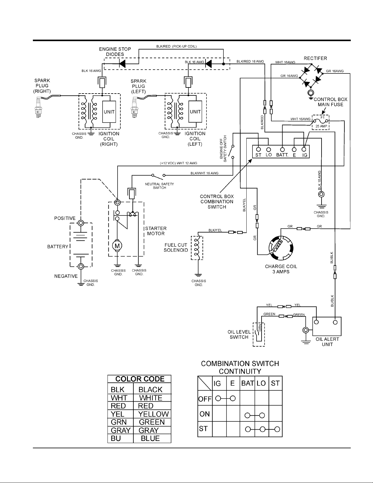
ENGINE WIRING DIAGRAM
SP2S20H PAVEMENT SAW • OPERATION MANUAL — REV. #1 (02/17/12) — PAGE 45
Page 46

Symptom Possible Problem Solution
Diffi cult to start, fuel is available, but no spark
at spark plug.
Diffi cult to start, fuel is available, and spark is
present at the spark plug.
Diffi cult to start, fuel is available, spark is
present and compression is normal.
Diffi cult to start, fuel is available, spark is
present and compression is low.
No fuel present at carburetor.
TROUBLESHOOTING
Troubleshooting (Engine)
Spark plug bridging? Check gap, insulation or replace spark plug.
Carbon deposit on spark plug? Clean or replace spark plug.
Short circuit due to defi cient spark plug
insulation?
Improper spark plug gap? Set to proper gap.
Fuel reaching carburetor? Check fuel line.
Water in fuel tank? Flush or replace fuel tank.
Fuel fi lter clogged? Replace fuel fi lter.
Stuck carburetor? Check fl oat mechanism.
Spark plug is red? Check transistor ignition unit.
Spark plug is bluish white?
No spark present at tip of spark plug?
No oil? Add oil as required.
Oil pressure alarm lamp blinks upon starting?
(if applicable)
ON/OFF switch is shorted? Check switch wiring, replace switch.
Ignition coil defective? Replace ignition coil.
Improper spark gap, points dirty? Set correct spark gap and clean points.
Condenser insulation worn or short circuiting? Replace condenser.
Spark plug wire broken or short circuiting? Replace defective spark plug wiring.
Wrong fuel type?
Water or dust in fuel system? Flush fuel system.
Air cleaner dirty? Clean or replace air cleaner.
Choke open? Close choke.
Suction/exhaust valve stuck or protruded? Reseat valves.
Piston ring and/or cylinder worn? Replace piston rings and/or piston.
Cylinder head and/or spark plug not tightened
properly?
Head gasket and/or spark plug gasket damaged? Replace head and spark plug gaskets.
No fuel in fuel tank? Fill with correct type of fuel.
Fuel cock does not open properly?
Fuel fi lter/lines clogged? Replace fuel fi lter.
Fuel tank cap breather hole clogged? Clean or replace fuel tank cap.
Air in fuel line? Bleed fuel line.
Check spark plug insulation, replace if worn.
If insuffi cient compression, repair or replace
engine. If injected air leaking, correct leak. If
carburetor jets clogged, clean carburetor.
Check transistor ignition unit is broken, and
replace defective unit. Check if voltage cord
cracked or broken and replace. Check if
spark plug if fouled and replace.
Check automatic shutdown circuit, "oil
sensor". (if applicable)
Flush fuel system, and replace with correct
type of fuel.
Torque cylinder head bolts and spark plug.
Apply lubricant to loosen fuel cock lever,
replace if necessary.
PAGE 46 — SP2S20H PAVEMENT SAW • OPERATION MANUAL — REV. #1 (02/17/12)
Page 47

Symptom Possible Problem Solution
Weak in power, compression is proper and
does not misfi re.
Weak in power, compression is proper but
misfi res.
Engine overheats.
Rotational speed fl uctuates.
Recoil starter malfunctions. (if applicable)
Starter malfunctions.
Burns too much fuel.
Exhaust color is continuously "white".
Exhaust color is continuously "black".
Will not start, no power with key "ON". (if
applicable)
TROUBLESHOOTING
Troubleshooting (Engine) - continued
Air cleaner dirty? Clean or replace air cleaner.
Improper level in carburetor? Check fl oat adjustment, rebuild carburetor.
Defective spark plug? Clean or replace spark plug.
Improper spark plug? Set to proper gap.
Water in fuel system?
Dirty spark plug? Clean or replace spark plug.
Ignition coil defective? Replace ignition coil.
Spark plug heat value incorrect? Replace with correct type of spark plug.
Wrong type of fuel? Replace with correct type of fuel.
Cooling fi ns dirty? Clean cooling fi ns.
Intake air restricted?
Oil level too low or too high? Adjust oil to proper level.
Governor adjusted incorrectly? Adjust governor.
Governor spring defective? Replace governor spring.
Fuel fl ow restricted? Check entire fuel system for leaks or clogs.
Recoil mechanism clogged with dust and
dirt?
Spiral spring loose? Replace spiral spring.
Loose, damaged wiring?
Battery insuffi ciently charged? Recharge or replace battery.
Starter damaged or internally shorted? Replace starter.
Over-accumulation of exhaust products?
Wrong spark plug?
Lubricating oil is wrong viscosity? Replace lubricating oil with correct viscosity.
Worn rings? Replace rings.
Air cleaner clogged? Clean or replace air cleaner.
Choke valve set to incorrect position? Adjust choke valve to correct position.
Carburetor defective, seal on carburetor
broken?
Poor carburetor adjustment, engine runs too
rich?
ON/OFF device not activated ON? Turn on ON/OFF device.
Battery disconnected or discharged?
Ignition switch/wiring defective? Replace ignition switch. Check wiring.
Flush fuel system and replace with correct
type of fuel.
Clear intake of dirt and debris. Replace air
cleaner elements as necessary.
Clean recoil assembly with soap and water.
Ensure tight, clean connections on battery
and starter.
Check and clean valves. Check muffl er and
replace if necessary.
Replace spark plug with manufacturer's
suggested type.
Replace carburetor or seal.
Adjust carburetor.
Check cable connections. Charge or replace
battery
SP2S20H PAVEMENT SAW • OPERATION MANUAL — REV. #1 (02/17/12) — PAGE 47
Page 48

Symptom Possible Problem Solution
Blade slows or Stops cutting,still remains on
blade.
Blade does not cut straight and/or true.
Blade discoloring, crackling and/or wearing
excessively.
TROUBLESHOOTING
Troubleshooting (Blades)
Blade too hard for the material being
cut?
Engine Torgue diminished because of
loose V-Belts?
Insuffi cent Engine power? Check Throttle setting. Check Engine horespower.
Improper direction of rotation?
Blade is slipping on the blade shaft?
Blade being used on misaligned saw?
Blade is excessively hard for the material
being cut?
Blade being used at improper RPM?
Blade improperly mounted on arbor
shoulders and fl anges?
Excessive force applied to blade while
cutting?
Blade too hard for the material being
cut?
Blade improperly mounted on arbor
shoulders and fl anges?
Blade not receiving enough cooling
water?
Abor hole out of round?
Incorrect blade chosen for material being
cut?
Excessive force applied to blade while
cutting?
Consult Dealer or Multiquip for correct blade. Try
cutting very soft material (sandstone, silica brick,
cinder block) to "Redress" the blade.
Tighten and/or replace V-Belts.
Check that the blade is oriented and rotational
arrow points are in a "Down-Cutting" direction.
Check that the blade and fl ange pin are properly
installed on the blade shaft.
Check blade shaft bearings and alignment
integrity.
Check specifi cations of the blade with the
material being cut. Consult Dealer or Multiquip for
information.
Ensure blade surface feet per minute speed
(SFPM) is approximately 6,000.
Ensure blade is properly affi xed on the blade
shaft.
Do not force the blade in the cut. Apply a slow,
steady pace to sawing.
Consult Dealer or Multiquip for correct blade. Try
cutting very soft material (sandstone, silica brick,
cinder block) to"Redress" the blade.
Ensure blade is properly affi xed on the blade
shaft. Ensure the blade fl anges are clean and free
of debris.
Ensure proper fl ow and volume of water is
provided for blades.
Ensure blade is properly affi xed on the blade
shaft.
Check specifi cations of the blade with the
material being cut. Consult Dealer or Multiquip for
information.
Do not force the blade in the cut. Apply a slow,
steady pace to sawing.
PAGE 48 — SP2S20H PAVEMENT SAW • OPERATION MANUAL — REV. #1 (02/17/12)
Page 49

NOTES
SP2S20H PAVEMENT SAW • OPERATION MANUAL — REV. #1 (02/17/12) — PAGE 49
Page 50

OPERATION MANUAL
HERE’S HOW TO GET HELP
© COPYRIGHT 2012, MULTIQUIP INC.
Multiquip Inc
trademarks are the property of their respective owners and used with permission.
This manual
The information and specifications included in this publication were in effect at the time of approval for printing. Illustrations, descriptions, references and technical data contained in
this manual are for guidance only and may not be considered as binding. Multiquip Inc. reserves the right to discontinue or change specifications, design or the information published
in this publication at any time without notice and without incurring any obligations.
PLEASE HAVE THE MODEL AND SERIAL
NUMBER ON-HAND WHEN CALLING
United StateS
Multiquip Corporate Office MQ Parts Department
18910 Wilmington Ave.
Carson, CA 90746
Contact: mq@multiquip.com
Service Department Warranty Department
800-421-1244
310-537-3700
Technical Assistance
800-478-1244 Fax: 310-943-2238
Tel. (800) 421-1244
Fax (800) 537-3927
Fax: 310-537-4259 800-421-1244
800-427-1244
310-537-3700
310-537-3700
Fax: 800-672-7877
Fax: 310-637-3284
Fax: 310-943-2249
mexico United Kingdom
MQ Cipsa Multiquip (UK) Limited Head Office
Carr. Fed. Mexico-Puebla KM 126.5
Momoxpan, Cholula, Puebla 72760 Mexico
Contact: pmastretta@cipsa.com.mx
Tel: (52) 222-225-9900
Fax: (52) 222-285-0420
Unit 2, Northpoint Industrial Estate,
Globe Lane,
Dukinfield, Cheshire SK16 4UJ
Contact: sales@multiquip.co.uk
Canada
Multiquip
4110 Industriel Boul.
Laval, Quebec, Canada H7L 6V3
Contact: jmartin@multiquip.com
Tel: (450) 625-2244
Tel: (877) 963-4411
Fax: (450) 625-8664
Tel: 0161 339 2223
Fax: 0161 339 3226
, the MQ logo and the Whiteman logo are registered trademarks of Multiquip Inc. and may not be used, reproduced, or altered without written permission. All other
MUST accompany the equipment at all times. This manual is considered a permanent part of the equipment and should remain with the unit if resold.
Your Local Dealer is:
PN: 35523
 Loading...