

Page 1

OPERATION MANUAL
StreetPro SERIES
MODEL SP1E16A
PROFESSIONAL PAVEMENT SAW
(5HP ELECTRIC MOTOR)
Revision #0 (04/14/10)
To find the latest revision of this
publication, visit our website at:
www.multiquip.com
THIS MANUAL MUST ACCOMPANY THE EQUIPMENT AT ALL TIMES.
PN: 38257
Page 2
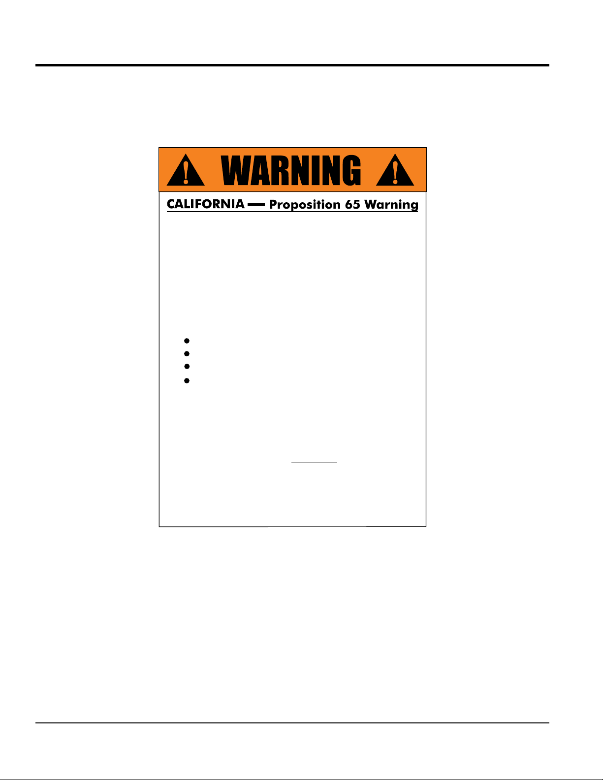
PROPOSITION 65 WARNING
Engine exhaust and some of
its constituents, and some dust created
by power sanding, sawing, grinding,
drillingandotherconstructionactivities
contains chemicals known to the State
of California to cause cancer, birth
defects and other reproductive harm.
Some examples of these chemicals are:
Leadfromlead-basedpaints.
Crystallinesilicafrombricks.
Cementandothermasonryproducts.
Arsenicandchromiumfrom chemically
treatedlumber.
Your risk from these exposures varies,
dependingonhowoftenyoudothistype
of work. To reduce your exposure to
these chemicals: work in aALWAYS
well ventilated area, and work with
approved safety equipment, such as
dust masks that are specially designed
to filter out microscopic particles.
PAGE 2 — SP1E16A PAVEMENT SAW • OPERATION MANUAL — REV. #0 (04/14/10)
Page 3
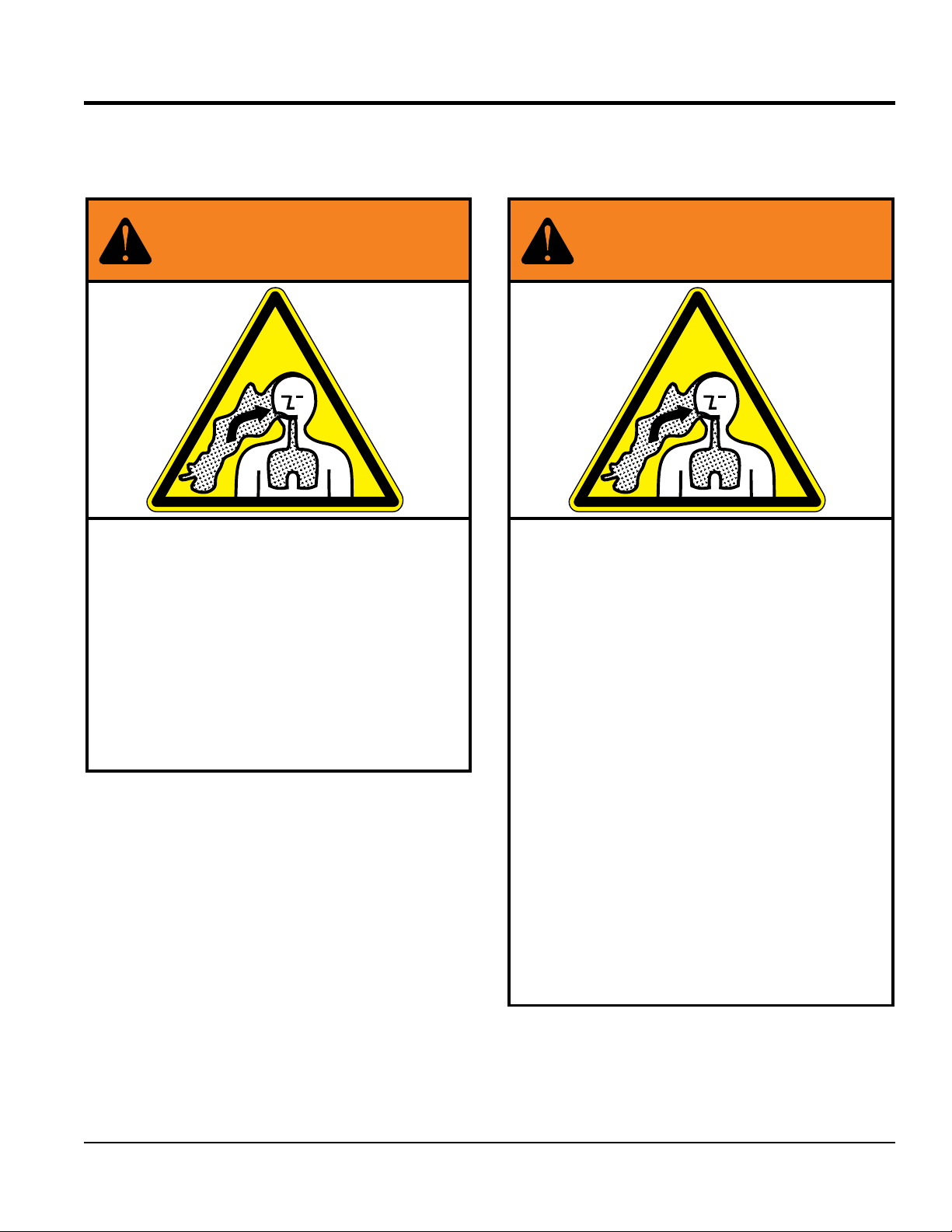
SILICOSIS/RESPIRATORY WARNINGS
WARNING
SILICOSIS WARNING RESPIRATORY HAZARDS
Grinding/cutting/drilling of masonry, concrete, metal and
other materials with silica in their composition may give
off dust or mists containing crystalline silica. Silica is a
basic component of sand, quartz, brick clay, granite and
numerous other minerals and rocks. Repeated and/or
substantial inhalation of airborne crystalline silica can
cause serious or fatal respiratory diseases, including
silicosis. In addition, California and some other
authorities have listed respirable crystalline silica as a
substance known to cause cancer. When cutting such
materials, always follow the respiratory precautions
mentioned above.
WARNING
Grinding/cutting/drilling of masonry, concrete, metal and
other materials can generate dust, mists and fumes
containing chemicals known to cause serious or fatal
injury or illness, such as respiratory disease, cancer,
birth defects or other reproductive harm. If you are
unfamiliar with the risks associated with the particular
process and/or material being cut or the composition of
the tool being used, review the material safety data
sheet and/or consult your employer, the material
manufacturer/supplier, governmental agencies such as
OSHA and NIOSH and other sources on hazardous
materials. California and some other authorities, for
instance, have published lists of substances known to
cause cancer, reproductive toxicity, or other harmful
effects.
Control dust, mist and fumes at the source where
possible. In this regard use good work practices and
follow the recommendations of the manufacturers or
suppliers, OSHA/NIOSH, and occupational and trade
associations. Water should be used for dust
suppression when wet cutting is feasible. When the
hazards from inhalation of dust, mists and fumes cannot
be eliminated, the operator and any bystanders should
always wear a respirator approved by NIOSH/MSHA for
the materials being used.
SP1E16A PAVEMENT SAW • OPERATION MANUAL — REV. #0 (04/14/10) — PAGE 3
Page 4

SP1E16A Pavement Saw
Proposition 65 Warning ........................................... 2
Silicosis/Respiratory Warnings ................................ 3
Table Of Contents .................................................... 4
Training Checklist ..................................................... 6
Daily Pre-Operation Checklist ................................. 7
Safety Information .............................................. 8-12
Specifications/Dimensions ..................................... 13
General Information ............................................... 14
TABLE OF CONTENTS
Controls And Components .................................... 15
Inspection/Setup ............................................... 16-17
Blades ............................................................... 18-20
Initial Startup ......................................................... 20
Operation ............................................................... 21
Maintenance ..................................................... 21-22
Troubleshooting (Electric Motor) ............................ 22
Troubleshooting (Saw) ........................................... 23
NOTICE
Specifications are subject to change without notice.
PAGE 4 — SP1E16A PAVEMENT SAW • OPERATION MANUAL — REV. #0 (04/14/10)
Page 5

NOTES
SP1E16A PAVEMENT SAW • OPERATION MANUAL — REV. #0 (04/14/10) — PAGE 5
Page 6

TRAINING CHECKLIST
Training Checklist
No, Description OK? Date
1
2
3
4 Safety controls.
5 Emergency stop procedures.
6 Startup of machine.
7 Starting a cut.
8 Pavement cutting techniques.
9 Stopping a cut.
10
11 Shutdown of machine.
Read operation manual
completely.
Machine layout, location of
components.
Operation of controls (machine
not running).
Restart after stopping blade within
work surface — explanation
12 Lifting of machine.
13 Machine transport and storage.
PAGE 6 — SP1E16A PAVEMENT SAW • OPERATION MANUAL — REV. #0 (04/14/10)
Page 7

DAILY PRE-OPERATION CHECKLIST
Daily Pre-Operation Checklist
1 Hardware and damage check
2 Condition of blade
3 ON/OFF switch
4 Condition of power cable
SP1E16A PAVEMENT SAW • OPERATION MANUAL — REV. #0 (04/14/10) — PAGE 7
Page 8
SAFETY INFORMATION
Do not operate or service the equipment before reading
Potential hazards associated with the operation of this
the entire manual. Safety precautions should be followed
at all times when operating this equipment.
Failure to read and understand the safety
messages and operating instructions could
result in injury to yourself and others.
SAFETY MESSAGES
The four safety messages shown below will inform you
about potential hazards that could injure you or others. The
safety messages specifi cally address the level of exposure
to the operator and are preceded by one of four words:
DANGER, WARNING, CAUTION or NOTICE.
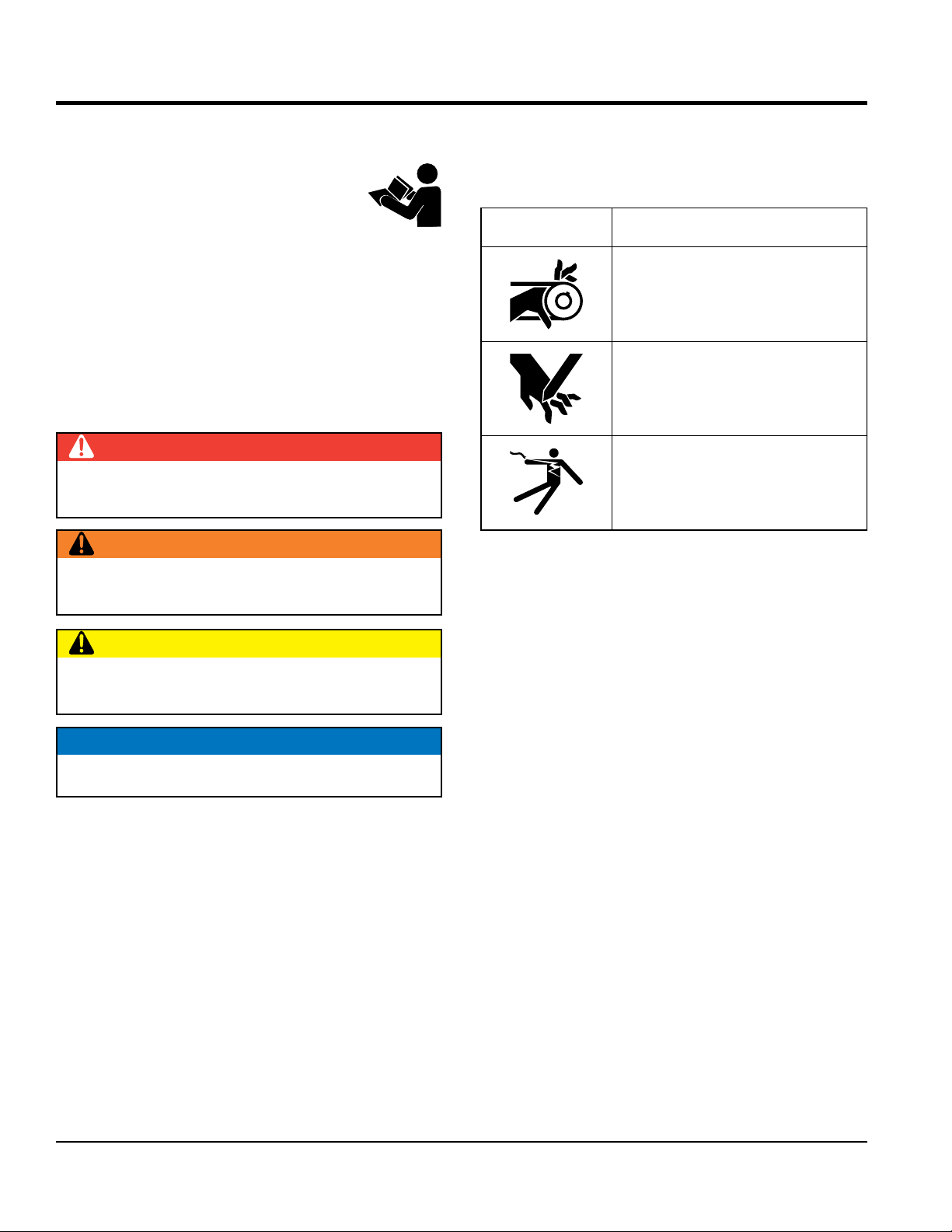
SAFETY SYMBOLS
DANGER
Indicates a hazardous situation which, if not avoided,
WILL result in DEATH or SERIOUS INJURY.
WARNING
Indicates a hazardous situation which, if not avoided,
COULD result in DEATH or SERIOUS INJURY.
equipment will be referenced with hazard symbols which
may appear throughout this manual in conjunction with
safety messages.
Symbol Safety Hazard
Rotating parts hazards
Cutting and crushing hazards
Electric shock hazards
CAUTION
Indicates a hazardous situation which, if not avoided,
COULD result in MINOR or MODERATE INJURY.
NOTICE
Addresses practices not related to personal injury.
PAGE 8 — SP1E16A PAVEMENT SAW • OPERATION MANUAL — REV. #0 (04/14/10)
Page 9

GENERAL SAFETY
NOTICE
This equipment should only be operated by trained and
Whenever necessary, replace nameplate, operation and
accident due to equipment modifi cations. Unauthorized
recommended by Multiquip for this equipment. Damage
keep
Also, know the phone numbers
fi re department.
SAFETY INFORMATION
CAUTION
NEVER operate this equipment without proper protective
clothing, shatterproof glasses, respiratory protection,
hearing protection, steel-toed boots and other protective
devices required by the job or city and state regulations.
Avoid wearing jewelry or loose fi tting clothes that may
snag on the controls or moving parts as this can cause
serious injury.
NEVER operate this equipment when not
feeling well due to fatigue, illness or when
under medication.
NEVER operate this equipment under the
infl uence of drugs or alcohol.
ALWAYS clear the work area of any debris, tools, etc.
that would constitute a hazard while the equipment is
in operation.
qualifi ed personnel 18 years of age and older.
safety decals when they become diffi cult read.
Manufacturer does not assume responsibility for any
equipment modifi cation will void all warranties.
NEVER use accessories or attachments that are not
to the equipment and/or injury to user may result.
ALWAYS know the location of the nearest
fi re extinguisher.
ALWAYS know the location of the nearest
fi rst aid kit.
ALWAYS know the location of the nearest phone or
a phone on the job site.
of the nearest ambulance, doctor and
This information will be invaluable in the case of an
emergency.
No one other than the operator is to be in the working
area when the equipment is in operation.
DO NOT use the equipment for any purpose other than
its intended purposes or applications.
SP1E16A PAVEMENT SAW • OPERATION MANUAL — REV. #0 (04/14/10) — PAGE 9
Page 10

SAW SAFETY
NOTICE
placed on appropriate
leaving or when using on a slope. Some saws utilize a
brake system where the brakes are automatically applied
If saw has a parking brake, ensure that the parking brake
parking on a slope. Turning the saw across the angle of
the slope will help prevent accidental downhill movement.
start saw
use on excessive slopes or on extremely uneven
keep the machine in proper running condition.
Make sure there is no buildup of concrete, grease, oil or
store equipment properly when it is not being
used. Equipment should be stored in a clean, dry location
out of the reach of children and unauthorized personnel.
SAFETY INFORMATION
DANGER.
NEVER operate the equipment in an explosive
atmosphere or near combustible materials. An
explosion or fi re could result causing severe
bodily harm or even death.
WARNING
Accidental starting can cause severe injury
or death. ALWAYS place the ON/OFF
switch in the OFF position.
NEVER disconnect any emergency or safety devices.
Thes e dev ices are intended for operator safet y.
Disconnection of these devices can cause severe injury,
bodily harm or even death. Disconnection of any of these
devices will void all warranties.
CAUTION
Anytime the saw is lifted onto its nose or tilted fully
back, such as for maintenance access, the high end of
the saw MUST be blocked up to prevent the possibility
of crush injury.
ALWAYS ensure saw is securely
blocks or jackstands when performing maintenance
requires elevation of the saw.
If saw has brakes, ensure brakes are applied when
when the motor is stopped.
is engaged and holds the saw safely in place when
ALWAYS block the saw with appropriate blocks when
leaving the saw parked on a slope.
To prevent unexpected loss of control, DO NOT
on a sloping surface
DO NOT
surfaces
ALWAYS
Fix damage to machine and replace any broken parts
immediately.
debris on the machine.
ALWAYS
PAGE 10 — SP1E16A PAVEMENT SAW • OPERATION MANUAL — REV. #0 (04/14/10)
Page 11

SAFETY INFORMATION
BLADE SAFETY
ELECTRIC MOTOR SAFETY
disconnect AC power plug from power source
cables or cords when
connecting equipment to power source. Inspect for cuts
Ensure that cables and cords will not be tripped over or
make certain that proper power or extension
cord has been selected for the job. See Cable Selection
Rotating blade can cut and crush. ALWAYS
keep hands and feet clear while operating
the saw.
NEVER operate the saw without blade guards
and covers in place. Exposure of the diamond
blade must not exceed 180 degrees.
ALWAYS ensure that unit is unplugged
(disconnected) when installing blade.
Verify the electric motor is set to the OFF position before
installing a blade.
A LWAYS in spect blad e be fo re ea ch
use. The blade should exhibit no cracks,
dings, or fl aws in the steel centered core
and/or rim. Center (arbor) hole must be
undamaged and true.
NOTICE
WARNING
CAUTION
NOTICE
Operate electric motor only at the specifi ed voltage
indicated on the nameplate.
DO NOT spray water onto electric motor.
ALWAYS
before moving saw.
ALWAYS make sure the ON/OFF switch
on the electric motor is in the OFF position
when not in use and before inserting the
mixer’s power plug into an AC receptacle.
POWER CORD/CABLE SAFETY
DANGER
NEVER let power cords or cables lay in water.
NEVER stand in water while AC power from the
generator is being transferred to a load.
NEVER use damaged or worn
Use proper blades and follow blade manufacturer’s
recommendations. Match the blade RPM (blade shaft RPM)
to the recommended blade surface feet per minute (SFPM).
Ensure the 5/8" blade-mounting bolt is tightened to 125-
175 foot lbs. of torque.
ALWAYS examine blade flanges for damage and
excessive wear.
Ensure the blade is marked with an operating speed
greater than the spindle speed of the saw.
Only cut the material that is specifi ed for the diamond blade.
Read the specifi cation of the diamond blade to ensure the
proper tool has been matched to the material being cut.
If wet cutting, ensure a WET CUTTING blade is being
used and that the water supply system to the blade is
properly functioning and being used.
DO NOT drop the diamond blade on ground or surface.
Ensure that the blade is mounted for proper operating direction.
in the insulation.
NEVER grab or touch a live power
cord or cable with wet hands. The
possibility exists of electrical shock,
electrocution or death.
CAUTION
trapped underneath the saw.
NOTICE
ALWAYS
Chart in this manual.
Adhere to the blade manufacturer’s recommendations
on handling, storage and safe usage of blades.
SP1E16A PAVEMENT SAW • OPERATION MANUAL — REV. #0 (04/14/10) — PAGE 11
Page 12

SAFETY INFORMATION
LIFTING SAFETY
ENVIRONMENTAL SAFETY
pour waste, oil or fuel directly onto the ground,
Recyclers and manufactures alike promote the process
CAUTION
NEVER allow any person or animal to stand underneath
the equipment while lifting.
DO NOT attempt to lift the saw by the guards, handle
bars or front pointers.
NOTICE
When lifting of the saw is required, use a forklift.
DO NOT lift machine to unnecessary heights.
NEVER lift the equipment while the motor is running.
ALWAYS use ramps capable of supporting the weight of
the saw and the operator to load and unload the saw.
TRANSPORTING SAFETY
NOTICE
ALWAYS shutdown saw before transporting.
ALWAYS tie down equipment during transport by
securing the equipment with rope.
Ensure that the diamond blade does not come into contact
with the ground or surface during transportation.
NEVER transport the saw to or from the job site with the
blade mounted.
NOTICE
Dispose of hazardous waste proper ly.
Examples of potentially hazardous waste
are used motor oil, fuel and fuel fi lters.
DO NOT use food or plastic containers to dispose of
hazardous waste.
DO NOT
down a drain or into any water source.
DECOMISSIONING
Metal Parts Recycling
NOTICE
When the life-cycle of this equipment is over,
it is recommended that the steel frame and
all other metal parts be sent to a recycling
center.
Metal recycling involves the collection of metal from
discarded products and its transformation into raw
materials to use in manufacturing a new product.
of recycling metal. Using a metal recycling center
promotes an energy cost savings.
Rubber Parts Recycling
PAGE 12 — SP1E16A PAVEMENT SAW • OPERATION MANUAL — REV. #0 (04/14/10)
NOTICE
Contact your country's Department of
Public Works or recyling agency in your
area and arrange for proper disposal of
any rubber components associated with
this equipment.
Page 13

SPECIFICATIONS/DIMENSIONS
Table 1. Electric Motor Specifications
Electric Motor 5HP, Single Phase 230 VAC Electric Motor
Max Output 5 HP/3450 RPM
Starting Method Electric
Input Voltage 230 VAC
Max Amps 19.5
Approx. Weight 72 lbs. (32.7 kg)
Phase Single
Frequency 60 Hz
Power Factor 99
Approx. Dimensions
(L x W x H)
17.25 x 8.63 x 9 in.
(438 x 219 x 229mm)
G
C
B
A
F
E
D
Figure 1. SP1E16A Dimensions
Table 2. SP1E16A Dimensions
Reference Letter Description Dimension (cm)
A Max Height 37.0 In. (94 cm)
B Max Length (Front Pointer Raised) 32.0 In. (80 cm)
C Max Length (Front Pointer Lowered) 54.5 In. (138 cm)
D Max Width 21.5 In. (55 cm)
E Rear Wheel Base 17.0 In. (40 cm)
F Front Wheel Base 10.0 In. (25.4 cm)
G Handle Bar Width 21.5 In. (55 cm)
SP1E16A PAVEMENT SAW • OPERATION MANUAL — REV. #0 (04/14/10) — PAGE 13
Page 14

GENERAL INFORMATION
The Multiquip SP1E16A walk-behind saw is designed for
wet or dry cutting of concrete or asphalt utilizing diamond
blades. These saws have been engineered for general
and industrial flat sawing applications.The reinforced
steel box frame design adds strength necessary to reduce
vibrations while cutting. Minimizing vibrations enhances the
performance of the blade and extends the life of the saw.
Heavy-duty front and rear axles, sturdy oversized wheels,
and industrial under carriage assembly ensure accurate
tracking and years of reliable use.
Additionally, the general weight-to-strength ratio design
of the frame and chassis assembly provides for optimum
weight distribution to keep the blade running true in the
cut. A rugged blade shaft bearing assembly ensures
minimal flutter and shaft harmonics providing the most
advantageous condition for a diamond blade at operating
speeds.
The SP1E16A saw comes standard with a 16-inch blade
guard and can handle diamond blades ranging in size from
12-16-inch in diameter.
The blade shaft accommodates a 1" arbor.
An ACME thread, manual raise/lower assembly, easily
raises and lowers the blade and locks it into position to
ensure a constant depth cut. The SP1E16A is equipped with
a retractable cutting guide, oversized roller bearing wheels,
industrial blade shaft berings, and a rigid steel frame.
POWER PLANTS
phase electric motor. Blade rotation is belt driven.
All Multiquip SP1E16A saws are designed, engineered
and manufactured with strict adherence to American
National Standards Institute, Inc. (ANSI) guidelines
B7.1 and B7.5.
WATER SYSTEM
The SP1E16A saw provides a hardy water plumbing
system that evenly distributes optimum water volume and
flow rate to both sides of the blade to keep the blade cool
when cutting. The basic water system consist of a standard
"garden hose" valve that connects the water source (via a
hose) to the saw.
FEATURES
Super-rigid box frame- ensures straight cuts while
resisting warping and vibration.
Rugged roller bearing wheels for long service life.
Comfortable grip handles
Easy cranking for manually raising/lowering the blade to
the desired cutting height.
Hinged front, lift-up blade guard is designed to provide
easy blade replacement.
Saw position guide helps ensure straight cuts.
Water system provides optimum flow and volume of
water to both sides of the blade.
The SP1E16A saw is generally classified in the industry as
a "LOW to MEDIUM " horsepower saw. This classification
is particularly useful when selecting the proper diamond
blade for an application.
Refer to the electric motor Owner's Manual for specific
instructions regarding motor operation and maintenance
practices.
The SP1E16A saw is powered by a 5.0 HP, 230 VAC single-
PAGE 14 — SP1E16A PAVEMENT SAW • OPERATION MANUAL — REV. #0 (04/14/10)
Page 15

CONTROLS AND COMPONENTS
1
10
2
3
Figure 2. SP1E16A Controls and Components
Figure 2 shows the location of the basic controls and
components for the SP1E16A. Listed below is a brief
explanation of each control or component.
1. Hand Grips/Handlebar — When operating the saw,
place both hands on each grip to maneuver the saw.
Replace hand grips when they become worn or
damaged.
2. H andle Lock — Lock bla de depth to de sired
position.
3. Garden Hose Connecter — Connect to water source
to provide blade cooling while cutting concrete or
asphalt.
4. W h e els/C a rriag e A ssemb ly — Hea vy-du t y
polyurethane wheels with permanently sealed ball
bearings.
5. Cutting Blade — Use appropriate type blades for
cutting concrete or asphalt. Requires 1" arbor.
6. Blade Guard — Covers saw blade and flips up to allow
blade to be changed.
7. Belt Tension Adjuster — Adjusts belt tension.
14
16
8
9
15
4
8. Front Pointer — Front pointer wheel assists in straight
tracking.
9. Front Pointer Arm — Stows up for storage and pivots
down for use.
10. Cutting Depth Adjuster — turn operating crank
clockwise or coun ter-clockwise to adjust the cutting
depth up or down.
11. Blade Coolant System — Provides cooling water to
blade during cutting operations.
12. V-Belt Cover — Remove this cover to gain access
to the V-belt. NEVER operate the saw with this cover
removed.
13. Arbor Shaft Grease Zerks — Conveniently located
for lubrication.
14. On/Off Switch — Turn to the "ON" position to allow
motor to be started and turn to the "OFF" position to
shut the motor off.
15. Electric Motor — 230 VAC, 60 Hz, single phase @
19.5 Amps
16. Power Cable — Connect to a 230 VAC, power source
@ 19.5 Amps.
12
6
13
7
11
5
SP1E16A PAVEMENT SAW • OPERATION MANUAL — REV. #0 (04/14/10) — PAGE 15
Page 16

INSPECTION/SETUP
INSPECTION/SETUP
1. Read and fully understand this manual,
the safety intructions in particular, and
the motor manufacturer's manual supplied
with the saw.
2. Select the correct blade for each application. If abrasive
blades are used, MAKE CERTAIN they are designed
for use on a concrete floor saw. They must be reinforced
and have a hole for the driving pin. When wet cutting
with an abrasive blade, MAKE CERTAIN the blade is
intended for wet cutting. Water will destroy a dry cut
abrasive blade. Some diamond blades require water
cooling and failure to do so will destroy them almost
immediately. Other diamond blades can be used with or
without water. Refer to the Blades and Blade Placement
sections in this manual for further information.
3. Handle all blades with care and NEVER use a damaged
blade. NEVER use an abrasive blade that has been
dropped.
Electric Motor
1. The motor should be connected to a power source in
compliance with all local electrical codes. This must
be performed by a qualified electrician. After this
connection is made, it will be necessary to check the
rotation of the motor shaft. The shaft rotation MUST
be counter-clockwise when viewing the motor from
the shaft extension end. If the rotation of the shaft is
incorrect make the necessary changes for the correct
shaft rotation.
WARNING
ALWAYS use a grounded extension cord and
make certain the motor is connected to a
properly grounded electrical circuit to protect
the operator from possible electric shock.
DANGER
ALWAYS use a grounded (3-wire) extension cord and
MAKE CERTAIN that the motor is connected to a
properly grounded electric circuit to protect the operator
from possible electric shock.
NEV ER touch the power
cord with wet hands or while
standing in water when it is
connected to a power source.
The possibly exists of electrical
shock (electrocution) or even
death. NEVER spray water
directly on the electric motor.
Guards And Covers
WARNING
NEVER operate the saw without blade guards and
covers in place. DO NOT operate with the front of
the blade guard raised. The blade exposure cannot
exceed 180 degrees during operation. Adhere to the
safety guidelines of the American National Standards
Institute (ANSI) B7.1 and B7.5.
2. MAKE CERTAIN the rated line voltage is at the motor
when cutting. Motors can burn out when the voltage
falls 10% below the voltage rating of the motor. Also
use the correct heavy duty circuit breakers or fuses in
the circuit.
3. MAKE CERTAIN the correct size extension cord is
used. Undersize wires will burn out motors. Use the
following chart to determine the extension cord size.
Table 3. Extension Cord Sizes
Motor Voltage 50' Long 75' Long 100' Long
5hp
single
phase
230 No. 10 No. 8 No. 6
PAGE 16 — SP1E16A PAVEMENT SAW • OPERATION MANUAL — REV. #0 (04/14/10)
BLADE GUARD
Figure 3. Blade Guard
Page 17

INSPECTION/SETUP
Check the following on the blade guard (Figure 3):
Ensure the capacity of the blade guard matches the
diameter of your diamond blade.
Check that the guard is bolted firmly upon the saw frame.
Check that the spring tensioned front cover of the guard
is firmly seated with the rear section of the guard and
there are no gaps. NEVER lift the blade guard while
cutting.
Ensure the v-belt cover is in place and securely fastened
during operation of the saw (Figure 4).
V-Belt Check
A worn or damaged V-belt can adversely affect the performance
of the saw. If a V-belt is defective or worn, replace ALL the
V-belts. V-belts should always be replaced in sets.
CAUTION
NEVER attempt to check the V-belt with the
engine running. Severe injury can occur.
Keep fingers, hands, hair, and clothing
away from all moving parts.
V-belt Alignment and Tensioning
This saw is equipped with a premium V-belt that has been
aligned and tensioned by factory personnel. The V-belt must
be aligned and tensioned for proper operation of the saw.
Use the following procedure to check the alignment of
V-belt:
1. Remove the bolts that secure the V-belt cover (Figure
4) to the saw frame.
2. Check uniform parallelism (Figure 5) of V-belt and
pulley (sheaves). Use a straight-edge or machinist's
square against both pulleys and adjust both pulleys
until equally aligned.
Figure 5. Pulley Alignment
3. Check V-belt tension by using a tension meter (3.0 lbs.)
against the inside belt at a mid point between the two
pulleys, or by deflecting the center belt at a mid point
3/16" (5 mm).
4. DO NOT over or under tighten the V-belt. Severe
damage can occur to the saw and engine crankshaft
if the belt is over-tensioned. A decrease of power to
the blade and poor performance will result if the belt
is under-tensioned (loose on pulleys).
NOTICE
V-belt alignment must be rechecked after adjusting
belt tension.
V-BELT COVER
Figure 4. V-Belt Cover
SP1E16A PAVEMENT SAW • OPERATION MANUAL — REV. #0 (04/14/10) — PAGE 17
Page 18

BLADES
Saw blades, or cutting disks, are available in either an
abrasive design or as diamond blades. Either blade will
work on the SP1E16A, however, diamond blades are
recommended. Ask your dealer about your specific cutting
application.
WARNING
Failure to thoroughly inspect the diamond
blade for operational safety could result in
damage to the blades or the saw and may
cause injury to the user or others in the
operating area.
Figure 6 highlights the components of a diamond blade.
3. Edge Of The Steel Core — Check the diameter
edge for discoloration (blue oxidation) indicating an
overheating condition caused by insufficient cooling
water/air. Overheating of blades may lead to loss of
core tension and/or increase the possibility for blade
failure. Check to make sure the steel core’s width is
uniform about the rim of the blade, and not succumbing
to an “under cutting” condition brought about by highly
abrasive material or improper under cutting core
protection.
4. Directional Arrow — Check to ensure that the blade is
oriented properly on the spindle for sawing. Reference
the directional arrow on the blade and place it so the
direction of rotation “downcuts” with the turn of the
shaft.
5. Diamond Segment or Rim — Ensure there are no
cracks, dings, or missing portions of the diamond
segment/rim. DO NOT
a segment or a portion of the rim
or missing segments/rims may cause damage to your
saw, and injury to the user or others in the operating
area.
use a blade that is missing
. Damaged and/
Figure 6. Diamond Blade
1. Drive Pin Hole — A commonly located hole on the
diamond blade core that prevents operational blade
slippage between the inner & outer blade flanges
(collars). Inspect the diameter of the hole to ensure
there is no distortion, and that a snug fit develops
between the hole and drive pin.
2. Stress Relief Holes (Gullets) — Check the steel core
for cracks that may have propagated from the slots
and/or gullets. Cracks indicate extreme fatigue failure
and if sawing continues, catastrophic failure will occur.
6. Specifications — Ensure that the blade specifications,
size, and diameter properly match up to the sawing
operation. Wet blades must have water to act as a
coolant. Utilizing a diamond blade not matched properly
to the task may result in poor performance and/or blade
damage.
7. Arbor Hole — It is essential that the arbor hole
diameter properly matches the shaft arbor (1"), and
that it is free from distortions. Correct blade flanges
(collars) must be used. The inside face of the flanges
must be clean & free of debris. An out of round arbor
condition will cause damage to the blade and the saw.
8. MAX RPM — This RPM reference is the maximum
safe operating speed for the blade selected. NEVER
exceed the max RPM on the diamond blade. Exceeding
the MAX RPM is dangerous, and may cause poor
performance and may damage the blade. All blades
used must be designed for the maximum spindle
RPM.
PAGE 18 — SP1E16A PAVEMENT SAW • OPERATION MANUAL — REV. #0 (04/14/10)
Page 19

BLADES
BLADE PLACEMENT
1. Blade Guard — Pivot the blade guard front cover all
the way back. The guard tension spring will keep the
front cover in position.
2. Blade Hex Nut — Unscrew the blade shaft nut (right
side loosens clockwise and tightens counter-clockwise
while the left side loosens counter-clockwise and
tightens clockwise. DO NOT overtighten the nut
(approximately 45-50 ft. lb/61-68 N/m) when finalizing
the assembly.
3. Outside Blade Flange (Collar) — Ensure that the
outside blade flange is placed flush against the
diamond blade. The inside surface of the flange must be
free of debris and permit a tight closure on the surface
of the blade core.
4. Diamond Blade — Ensure that the proper diamond
blade has been selected for the job. Pay close attention
to the directional arrows on the blade. The blade's
operating directional arrows must point in a "downcutting" direction to perform correctly. When placing
the blade onto the blade shaft, ensure the arbor hole
of the blade matches the diameter of the shaft.
Blade Removal and Replacement
CAUTION
ALWAYS ensure that unit is unplugged (disconnected)
when installing blade.
1. S et the motor ON/OFF switches to
the OFF position to prevent accidental
starting.
2. Place the saw on a stable level working
surface.
3. Ensure the blade is raised and the raise/lower crank
is locked into position.
NOTICE
When removing or installing a diamond blade, please
note that the blade retaining nuts are left and right-hand
threaded.
4. Lift up the blade guard cover to gain access to the
blade.
5. Inner Flange (Collar) — This flange is fixed upon the
blade shaft. The inside surface of the flange must be
free of debris and permit a tight closure on the surface
of the blade.
BLADE SPEED
A diamond blade’s performance is directly connected to
specific peripheral (rim) speeds.
The following shaft rotational speeds have been factory set
to ensure optimum blade performance.
SP1E16A 16-inch (406.4 mm) Capacity – 2,718 RPM
NOTICE
The following steps should be accomplished before
using the saw on any cutting surface.
WARNING
Dropping or forcing the blade onto the
cutting surface can severely damage the
diamond blade and may cause serious
damage to the saw and bodily harm.
Figure 7. Mounting the Diamond Blade
5. Use the provided blade nut wrench to remove and
install the blade (Figure 7).
6. Unscrew the spindle nut (right side loosens clockwise
and tightens counter-clockwise while the left side
loosens counter-clockwise and tightens clockwise).
DO NOT overtighten the nut (approximately 45-50 ft.
lb/61-68 N/m) when finalizing the assembly.
SP1E16A PAVEMENT SAW • OPERATION MANUAL — REV. #0 (04/14/10) — PAGE 19
Page 20

BLADES/INITIAL STARTUP
Cutting Depth Adjustment
The saw is equipped with a Raise/Lower Assembly that is
supported by the following components.
Raise/Lower Acme Screw
Jack Arm
Blade Guard
Adjusting Handle Crank
INITIAL STARTUP
CAUTION
DO NOT attempt to operate the saw until the Safety,
General Information and Inspection sections of this
manual have been read and thoroughly understood.
See motor manufacturer's operating manual.
NEVER operate the saw in a confined
area or enclosed area structure that does
not provide ample free flow of air.
ALWAYS wear approved eye and hearing
protection before operating the saw.
NEVER place hands or feet inside the belt
guard or blade guard while the engine is
running. ALWAYS shut the engine down
before performing any kind of maintenance
service on the saw.
DANGER.
NEV ER touch the power
cord with wet hands or while
standing in water when it is
connected to a power source.
The possibly exists of electrical
shock (electrocution) or even
death. NEVER spray water
directly on the electric motor.
3. Plug the other end of the extension cord into a 230VAC
power source. Remember to read the nameplate to
determine the motor's input voltage requirement.
WARNING
ALWAYS read the label on the electric motor before
applying power. The label will indicate the correct
power requirements for the motor. Remember, the use
of an incorrect input voltage will severely damage the
electric motor.
MAKE CERTAIN the motor is connected to a functional
ground fault circuit interrupter.
STARTING THE ELECTRIC MOTOR
1. Before starting, MAKE CERTAIN there is enough
clearance between the blade and the ground.
1. Ensure the diamond blade has been mounted correctly
and that it is raised above the surface you are about to saw.
2. Use an extension cord (see Table 3) of adequate
current carrying capacity. Insert the electric motor’s
power plug into one end of the extension cord.
CAUTION
MAKE CERTAIN that the electric motor's power switch
is in the OFF position before plugging the motor into
the power source.
DANGER
NEVER use a worn or frayed extension cord.
NEVER operate saw with V-belt cover removed.
PAGE 20 — SP1E16A PAVEMENT SAW • OPERATION MANUAL — REV. #0 (04/14/10)
2. Set the electric motor’s ON/OFF switch (Figure 8) to
the ON position.
ON
OFF
Figure 8. Electric Motor ON/OFF Switch
3. Before the saw is placed into operation, run the motor
for several minutes. Check for noises that would be
associated with loose guards and/or covers.
Page 21

OPERATION/MAINTENANCE
OPERATION
WARNING
ALWAYS keep clear of rotating or moving
parts while operating this equipment.
NOTICE
MAKE CERTAIN to raise the spindle high enough for the
blade to clear the pavement.
WARNING
MAKE CERTAIN the saw path is clear of debris and
obstructions to prevent tripping and/or falling onto the saw,
and to prevent debris from hitting the blade.
1. To begin sawing, lower the rotating blade allowing it to
cut to the preset depth.
2. When the blade has reached full cutting depth, slowly
walk behind the saw at a rate that will allow the motor
to operate without losing optimum RPM.
CAUTION
DO NOT try to cut faster than the blade will allow.
Cutting too fast will cause the blade to rise up out of
the cut. Improper cutting rate can decrease the life of
the motor and blades.
MAINTENANCE
WARNING
ALWAYS ensure that the motor ON/OFF switch is in the
OFF position, the power cable is unplugged, and that the
arbor shaft has COMPLETELY STOPPED ROTATING
before performing any of the following operations:
Removing or installing blades
Adjusting front or rear pointers
Lubricating any components
Removing motor mounting bolts
Inspecting, adjusting, or replacing drive belt, arbor shaft,
or arbor shaft bearings
Saw Blade Removal and Installation
See "Blade Removal and Replacement" section in this manual.
Front Pointer Adjustment
CAUTION
ALWAYS ensure that unit is unplugged (disconnected)
when installing blade.
The front pointer wheel has been set at the factory. Use
these procedures only if the pointer is suspect of being
out of alignment.
1. Chalk out a straight line on the prepared slab or cutting
surface.
NOTICE
Mark the cutting line clearly. ONLY saw in a straight line.
3. When the end of the cut has been reached, raise the
blade out of the cut by pulling back on the handlebars
(using a downward pressure) until the raise/lower rod
drops into its slots with the blade in the raised position.
4. If cutting is complete, turn the motor off and wait for
the blade to stop rotating.
STOPPING THE SAW
1. Place the electric motor’s ON/OFF switch in the OFF
position.
2. Disconnect the electric motor’s extension cord from
its power source.
SP1E16A PAVEMENT SAW • OPERATION MANUAL — REV. #0 (04/14/10) — PAGE 21
2. Use a 4 foot straight-edge or level by placing it flat
against the blade.
3. Adjust the front pointer wheel so it just touches the side
of the straight-edge or level.
4. Remove the straight-edge or level.
5. Position the front pointer and blade directly over the
chalk line.
6. Start the saw and lower the blade onto the chalk line.
7. Begin cutting and make sure the blade follows the chalk
line as closely as possible.
8. The pointer should follow the chalk line as well. If it does
not, adjust the pointer by loosening then tightening the
jam nuts on the pointer until the pointer follows the
same path as the blade.
Page 22

MAINTENANCE/TROUBLESHOOTING (ELECTRIC MOTOR)
Chassis Lubrication
Blade Shaft Bearings — Two zerk fittings are located
at the lower-front area of the saw. Lubricate before daily
use. Use a good quality automotive or general purpose
grease. Check and lubricate more often if unit is under
heavy use. Do not overfill bearings. Overfilling can
damage the grease seals which can result in bearing
exposure to dirt and contaminants which can then
shorten the life of the bearings. Excess grease can also
drip onto the cutting surface.
V-Belt
See "V-belt Alignment and Tensioning" section in this
manual.
TROUBLESHOOTING
Table 4. Troubleshooting (Electric Motor)
Symptom Possible Cause Solution
Is there power?
Is power cable plugged in? Plug in power cable.
Electric motor will not start.
Is ON/OFF switch placed in ON
position?
Defective cable? Check cable.
Electric motor continuously stops. Reset button OK? Check power source.
Electric motor RPM's too low. Low voltage? Check input voltage (230 VAC).
Electric motor RPM's too high. High voltage? Check input voltage (230 VAC).
Check power source. Check reset
button.
Place ON/OFF switch in ON position.
PAGE 22 — SP1E16A PAVEMENT SAW • OPERATION MANUAL — REV. #0 (04/14/10)
Page 23

Symptom Possible Problem Solution
Blade slows or stops cutting.
Blade does not cut straight and/or true.
Blade discoloring, crackling and/or wearing
excessively.
TROUBLESHOOTING (SAW)
Table 5. Blade Troubleshooting
Blade too hard for the material being cut?
Engine torque diminished because of loose
V-belt?
Insufficient engine power?
Improper direction of rotation?
Blade is slipping on the bladeshaft?
Blade being used on misaligned saw?
Blade is excessively hard for the material
being cut?
Blade being used at improper RPM?
Blade improperly mounted on arbor
shoulders and flanges?
Excessive force applied to blade while
cutting?
Blade too hard for the material being cut?
Blade improperly mounted on arbor
shoulders and flanges?
Blade not receiving enough cooling water?
Arbor hole out of round?
Incorrect blade chosen for material being
cut?
Excessive force applied to blade while
cutting?
Consult dealer or Multiquip for correct blade.
Try cutting very soft material (sandstone,
silica, brick, cinder block) to “redress” the
blade.
Tighten and/or replace V-belts.
Check throttle setting. Check engine
horsepower.
Check that the blade is properly oriented
and rotational arrow points in a down-cutting
direction.
Check that the blade and flange pins are
properly installed on the bladeshaft.
Check bladeshaft bearings and alignment
integrity.
Check specification of the blade with
the material being cut. Consult dealer or
Multiquip for information.
Ensure blade surface feet per minute speed
(SFPM) is approximately 6,000.
Ensure blade is proerly affixed on the
bladeshaft.
DO NOT force the blade in the cut. Apply a
slow and steady pace when sawing.
Consult dealer or Multiquip for correct blade.
Try cutting very soft material (sandstone,
silica, brick, cinder block) to “redress” the
blade.
Ensure blade is proerly affixed on the
bladeshaft.
Ensure proper flow and volume of water is
provided for wet cutting blades.
Ensure blade is properly affixed on the
bladeshaft.
Check specification of the blade with
the material being cut. Consult dealer or
Multiquip for information.
DO NOT force the blade in the cut. Apply a
slow and steady pace when sawing.
SP1E16A PAVEMENT SAW • OPERATION MANUAL — REV. #0 (04/14/10) — PAGE 23
Page 24

OPERATION MANUAL
HERE’S HOW TO GET HELP
Multiquip Inc and the MQ logo are registered trademarks of Multiquip Inc. and may not be used, reproduced, or altered without written permission. All other trademarks are the property
The information and specifi cations included in this publication were in effect at the time of approval for printing. Illustrations, descriptions, references and technical data contained in
this manual are for guidance only and may not be considered as binding. Multiquip Inc. reserves the right to discontinue or change specifi cations, design or the information published
PLEASE HAVE THE MODEL AND SERIAL
NUMBER ON-HAND WHEN CALLING
UNITED STATES
Multiquip Corporate Offi ce MQ Parts Department
18910 Wilmington Ave.
Carson, CA 90746
Contact: mq@multiquip.com
Mayco Parts Warranty Department
Tel. (800) 421-1244
Fax (800) 537-3927
800-427-1244
310-537-3700
Fax: 800-672-7877
Fax: 310-637-3284
800-306-2926
310-537-3700
Service Department Technical Assistance
800-421-1244
310-537-3700
Fax: 800-672-7877
Fax: 310-637-3284
Fax: 310-537-4259 800-478-1244 Fax: 310-631-5032
800-421-1244, Ext. 279
310-537-3700, Ext. 279
Fax: 310-537-1173
MEXICO UNITED KINGDOM
MQ Cipsa Multiquip (UK) Limited Head Offi ce
Carr. Fed. Mexico-Puebla KM 126.5
Momoxpan, Cholula, Puebla 72760 Mexico
Contact: pmastretta@cipsa.com.mx
Tel: (52) 222-225-9900
Fax: (52) 222-285-0420
Unit 2, Northpoint Industrial Estate,
Global Lane,
Dukinfi eld, Cheshire SK16 4UJ
Contact: sales@multiquip.co.uk
Tel: 0161 339 2223
Fax: 0161 339 3226
CANADA
Multiquip
4110 Industriel Boul.
Laval, Quebec, Canada H7L 6V3
Contact: jmartin@multiquip.com
© COPYRIGHT 2010, MULTIQUIP INC.
of their respective owners and used with permission.
This manual MUST accompany the equipment at all times. This manual is considered a permanent part of the equipment and should remain with the unit if resold.
Tel: (450) 625-2244
Tel: (877) 963-4411
Fax: (450) 625-8664
in this publication at any time without notice and without incurring any obligations.
Your Local Dealer is:
 Loading...