

Page 1

OPERATION AND PARTS MANUAL
STREET PRO 1 SERIES
MODEL SP1CE13H18
CONCRETE/ASPHALT SAW
(HONDA GX390 GASOLINE ENGINE)
Revision #3 (06/09/08)
To find the latest revision of this
publication, visit our website at:
www.multiquip.com
THIS MANUAL MUST ACCOMPANY THE EQUIPMENT AT ALL TIMES.
P/N 35213
Page 2
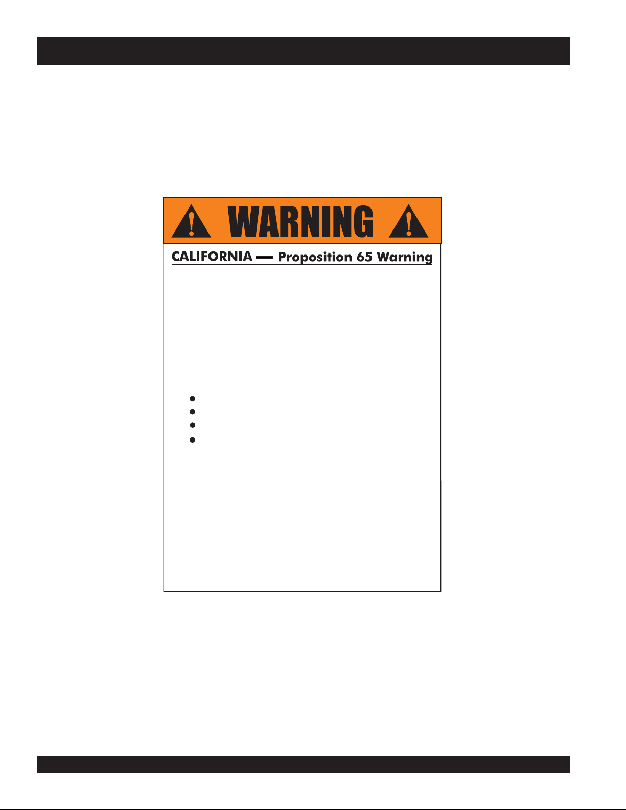
MQ STREET PRO 1 CE SAW — PROPOSITION 65 WARNING
Engine exhaust and some of
its constituents, and some dust created
by power sanding, sawing, grinding,
drillingandotherconstructionactivities
contains chemicals known to the State
of California to cause cancer, birth
defects and other reproductive harm.
Some examples of these chemicals are:
Leadfromlead-basedpaints.
Crystallinesilicafrombricks.
Cementandothermasonryproducts.
Arsenicandchromiumfrom chemically
treatedlumber.
Your risk from these exposures varies,
dependingonhowoftenyoudothistype
of work. To reduce your exposure to
these chemicals: work in aALWAYS
well ventilated area, and work with
approved safety equipment, such as
dust masks that are specially designed
to filter out microscopic particles.
PAGE 2 — SP 1 SAW CE— OPERATION AND PARTS MANUAL — REV. #3 (06/09/08)
Page 3
MQ STREET PRO 1 CE SAW — SILICOSIS/RESPIRATORY WARNINGS
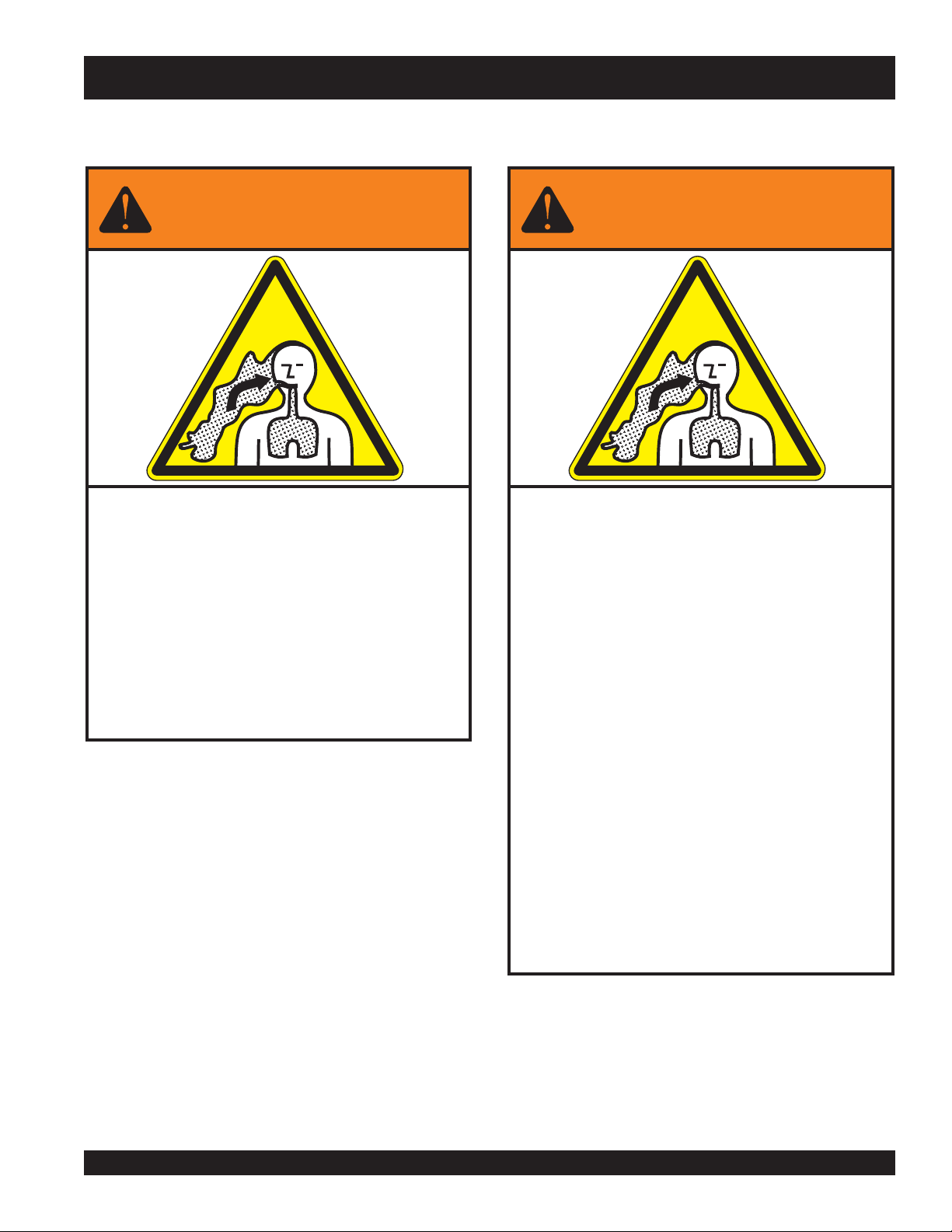
WARNING
SILICOSIS WARNING RESPIRATORY HAZARDS
Grinding/cutting/drilling of masonry, concrete, metal and
other materials with silica in their composition may give
off dust or mists containing crystalline silica. Silica is a
basic component of sand, quartz, brick clay, granite and
numerous other minerals and rocks. Repeated and/or
substantial inhalation of airborne crystalline silica can
cause serious or fatal respiratory diseases, including
silicosis. In addition, California and some other
authorities have listed respirable crystalline silica as a
substance known to cause cancer. When cutting such
materials, always follow the respiratory precautions
mentioned above.
WARNING
Grinding/cutting/drilling of masonry, concrete, metal and
other materials can generate dust, mists and fumes
containing chemicals known to cause serious or fatal
injury or illness, such as respiratory disease, cancer,
birth defects or other reproductive harm. If you are
unfamiliar with the risks associated with the particular
process and/or material being cut or the composition of
the tool being used, review the material safety data
sheet and/or consult your employer, the material
manufacturer/supplier, governmental agencies such as
OSHA and NIOSH and other sources on hazardous
materials. California and some other authorities, for
instance, have published lists of substances known to
cause cancer, reproductive toxicity, or other harmful
effects.
Control dust, mist and fumes at the source where
possible. In this regard use good work practices and
follow the recommendations of the manufacturers or
suppliers, OSHA/NIOSH, and occupational and trade
associations. Water should be used for dust
suppression when wet cutting is feasible. When the
hazards from inhalation of dust, mists and fumes cannot
be eliminated, the operator and any bystanders should
always wear a respirator approved by NIOSH/MSHA for
the materials being used.
SP 1 SAW CE— OPERATION AND PARTS MANUAL — REV. #3 (06/09/08) — PAGE 3
Page 4
MQ STREET PRO 1 CE SAW — TABLE OF CONTENTS
Proposition 65 Warning ............................................. 2
Silicosis/Respiratory Warnings .................................. 3
Table Of Contents ..................................................... 4
Parts Ordering Procedures ....................................... 5
Safety Message Alert Symbols .............................. 7-8
Rules For Safe Operation .................................... 9-11
Specifications (Saw) ................................................ 12
Specifications (Engine) ........................................... 13
General Information ................................................ 14
MQ — STREET PRO 1 CE SAW
Controls and Components ...................................... 15
Basic Engine ........................................................... 16
Preparation/Pre-Inspection ................................ 17-18
Blades ..................................................................... 19
Blade Placement ................................................20-21
Raise/Lower and Depth Stop .................................. 22
Initial Start-Up ....................................................23-24
Operation ........................................................... 25-26
Maintenance ...................................................... 27-28
Optional Water Tank ........................................... 29-30
Troubleshooting (Saw) ............................................ 31
Troubleshooting (Engine) ................................... 32-33
Explanation of Code in Remarks Column ............... 34
Suggested Spare Parts ........................................... 35
Decals ................................................................ 36-37
Engine, Belts and Pulleys .................................. 38-39
Undercarriage Assembly ................................... 40-41
Blade Assembly and Water System ................... 42-43
Pointer Assembly ............................................... 44-45
Water Tank (Optional) ........................................ 46-47
HONDA GX390K1QWT2/
GX390U1QWT2 ENGINE
Air Cleaner Assembly......................................... 48-49
Camshaft Assembly ...........................................50-51
Carburetor Assembly ......................................... 52-53
Control Assembly ............................................... 54-55
Crankcase Cover Assembly ............................... 56-57
Crankshaft Assembly .........................................58-59
Cylinder Barrel Assembly ................................... 60-61
Cylinder Head Assembly .................................... 62-63
Fan Cover Assembly .......................................... 64-65
Flywheel Assembly ............................................ 66-67
Fuel Tank Assembly ........................................... 68-69
Ignition Coil Assembly ........................................ 70-71
Muffler Assembly ............................................... 72-73
Piston Assembly ................................................. 74-75
Recoil Starter Assembly ..................................... 76-77
Labels ................................................................ 78-79
Terms and Conditions of Sale — Parts ................... 80
NOTE
Specifications and
part numbers are
subject to change
without notice.
PAGE 4 — SP 1 SAW CE— OPERATION AND PARTS MANUAL — REV. #3 (06/09/08)
Page 5
PARTS ORDERING PROCEDURES
Ordering parts has never been easier!
Choose from three easy options:
Effective:
January 1
st
, 2006
Best Deal!
Order via Internet (Dealers Only):
Order parts on-line using Multiquip’s SmartEquip website!
■
View Parts Diagrams
■
Order Parts
■
Print Specification Information
Goto www.multiquip.com and click on
Order Parts
to log in and save!
Order via Fax (Dealers Only):
All customers are welcome to order parts via Fax.
Domestic (US) Customers dial:
1-800-6-PARTS-7 (800-672-7877)
Non-Dealer Customers:
Contact your local Multiquip Dealer for
parts or call 800-427-1244 for help in
locating a dealer near you.
Order via Phone:
If you have an MQ Account, to obtain a
Username and Password, E-mail us at:
parts@multiquip.com.
To obtain an MQ Account, contact your
District Sales Manager for more information.
internet
Use the
on
Standard orders
and qualify for a 5% Discount
for all orders which include
complete part numbers.*
Fax
your order in and qualify for a 2% Discount
on
Standard orders
for all orders which include
complete part numbers.*
Domestic (US) Dealers Call:
1-800-427-1244
International Customers
their local Multiquip Representatives for
Parts Ordering information.
Note: Discounts Are Subject To Change
Note: Discounts Are Subject To Change
should contact
❒❒
❒
❒❒
❒❒
❒
❒❒
❒❒
❒
❒❒
❒❒
❒
❒❒
❒❒
❒
❒❒
❒❒
❒
❒❒
www.multiquip.com
SP 1 SAW CE— OPERATION AND PARTS MANUAL — REV. #3 (06/09/08) — PAGE 5
When ordering parts, please supply:
❒❒
❒
Dealer Account Number
Dealer Name and Address
Shipping Address (if different than billing address)
Return Fax Number
Applicable Model Number
Quantity, Part Number and Description of Each Part
All orders are treated as
and will ship the same day if received prior
to 3PM PST.
WE ACCEPT ALL MAJOR CREDIT CARDS!
❒❒
Standard Orders
Specify Preferred Method of Shipment:
✓
UPS/Fed Ex
■
Priority One
■
Ground
■ Next Day
■
Second/Third Day
✓ DHL
✓
Tr u c k
Page 6

NOTES
PAGE 6 — SP 1 SAW CE— OPERATION AND PARTS MANUAL — REV. #3 (06/09/08)
Page 7

MQ STREET PRO 1 CE SAW — SAFETY MESSAGE ALERT SYMBOLS
FOR YOUR SAFETY AND THE SAFETY OF OTHERS!
Safety precautions should be followed at all times when operating
this equipment. Failure to read, understand and comply with the
Safety Messages and Operating Instructions could result in injury
to yourself or others.
HAZARD SYMBOLS
NOTE
This Owner's Manual has been developed to provide
instructions for the safe and efficient operation of the
MULTIQUIP SP 1. For engine maintenance information,
please refer to the engine manufacturers' instructions
for data relative to its safe operation.
Before using this CONCRETE/ASPHALT SAW,
ensure that the operating individual has read and
understands all instructions in this manual.
SAFETY MESSAGE ALERT SYMBOLS
The three (3) Safety Messages shown below will inform you
about potential hazards that could injure you or others. The
Safety Messages specifically address the level of exposure to
the operator, and are preceded by one of three words: DANGER,
WARNING, or CAUTION.
Lethal Exhaust Gases
Engine exhaust gases contain poisonous
carbon monoxide. This gas is colorless and
odorless, and can cause death if inhaled.
NEVER operate this equipment in a confined
area or enclosed structure that does not
provide ample free flow air.
Guards and Covers In Place
NEVER operate the saw without blade guards
and covers in place. Adhere to safety
guidelines and applicable local regulations.
Burn Hazards
DANGERDANGER
DANGER
DANGERDANGER
You WILL be
if you DO NOT follow these directions.
WARNINGWARNING
WARNING
WARNINGWARNING
You CAN be KILLED or
you DO NOT follow these directions.
CAUTICAUTI
CAUTION
CAUTICAUTI
You CAN be
these directions.
Potential hazards associated with SP 1 operation will be
referenced with "
this manual, and will be referenced in conjunction with Safety
"
Message Alert Symbols
KILLED
INJURED
Hazard Symbols
or
SERIOUSLY INJURED
SERIOUSLY INJURED
if you DO NOT follow
" which appear throughout
".
if
Engine components can generate extreme heat.
To prevent burns, DO NOT touch these areas
while the engine is running or immediately after
operations. NEVER operate the engine with
heat shields or heat guards removed.
Rotating Parts
NEVER operate equipment with covers, or
guards removed. Keep fingers,
and
clothing
prevent injury.
hands, hair
away from all moving parts to
SP 1 SAW CE— OPERATION AND PARTS MANUAL — REV. #3 (06/09/08) — PAGE 7
Page 8
MQ STREET PRO 1 CE SAW — SAFETY MESSAGE ALERT SYMBOLS
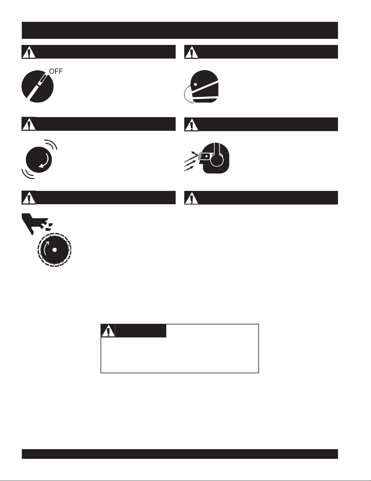
Accidental Starting
ALWAYS place the engine ON/OFF
switch in the OFF position, when the saw
is not in use.
Over Speed Conditions
NEVER tamper with the factory settings of the
engine governor. Personal injury and damage
to the engine or equipment can result if
operating in speed ranges above maximum
allowable.
Rotating Blade
Rotating blade can cut and crush. Keep
hands and feet clear.
Respiratory Hazard
ALWAYS wear approved respiratory protection.
Sight and Hearing hazard
ALWAYS wear approved eye and hearing
protection.
Equipment Damage Messages
Other important messages are provided throughout this manual
to help prevent damage to your concrete saw, other property, or
the surrounding environment.
CAUTION
This
concrete/asphalt saw
environment could be damaged if you do not follow
instructions.
PAGE 8 — SP 1 SAW CE— OPERATION AND PARTS MANUAL — REV. #3 (06/09/08)
, other property, or the surrounding
Page 9
MQ STREET PRO 1 CE SAW — RULES FOR SAFE OPERATION
RULES FOR SAFE OPERATION
WARNING
Failure to follow instructions in this manual may lead to
serious injury or even death! This equipment is to be operated
by trained and qualified personnel only! This equipment is
for industrial use only.
■
NEVER operate this equipment when not feeling well due to
fatigue, illness or taking medicine.
■
NEVER operate the saw under the influence or drugs or alcohol.
■
Replace nameplate, operation and safety decals when they
become difficult to read.
■
ALWAYS check the saw for loosened hardware such as nuts
and bolts before starting.
The following safety guidelines should always be used when
operating the SP 1.
SAFETY
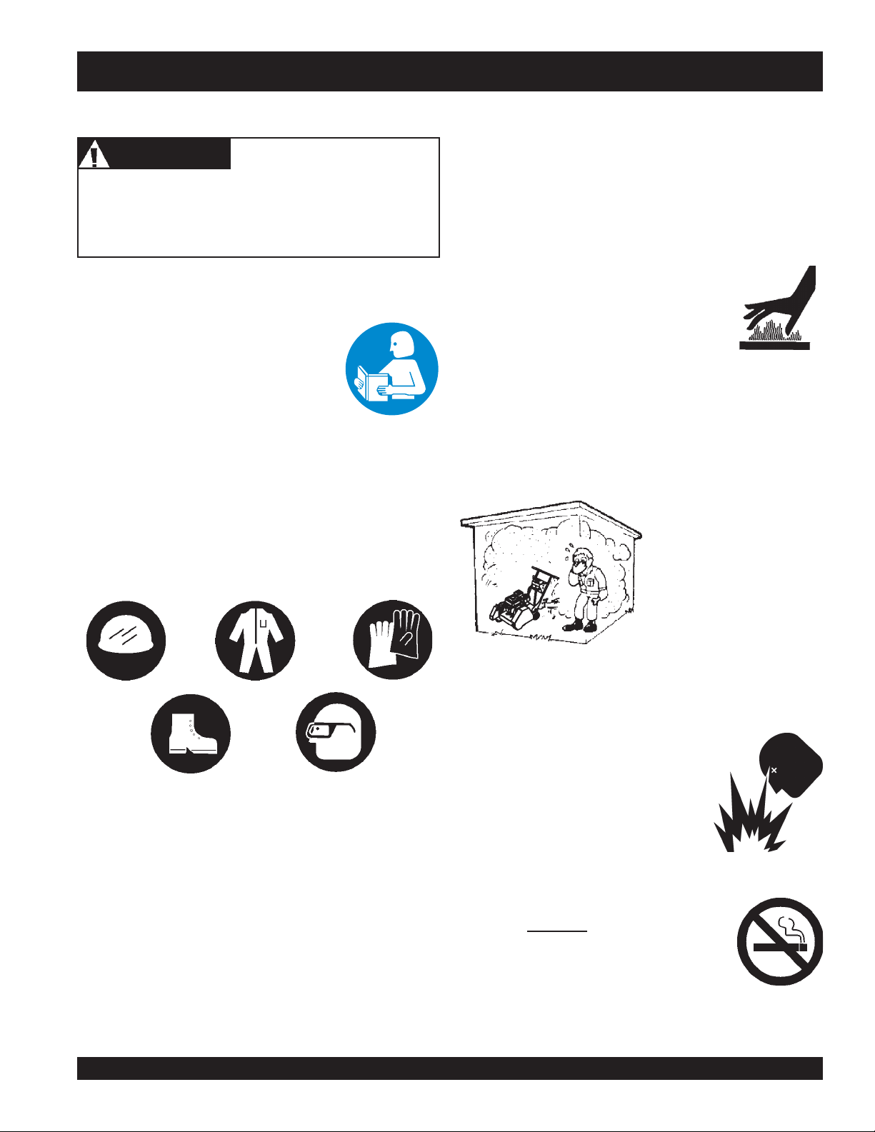
■
DO NOT operate or service this equipment
before reading this entire manual. The
manual must be kept available and accessible
to the operator.
■
This equipment should not be operated by persons under the
minimum statutory age limit.
■
NEVER use this machine for any purpose other than those
described in this manual.
■
NEVER operate the saw without proper protective clothing,
shatterproof glasses, steel-toed boots and other protective
devices required for the job.
■
NEVER touch the hot exhaust manifold, muffler
or cylinder. Allow these parts to cool before
servicing the saw.
■
High Temperatures – Allow the engine to cool before adding
fuel or performing service and maintenance functions. Contact
hot!
with
■
The engine of this saw requires an adequate free flow of
cooling air. NEVER operate the saw in any enclosed or narrow
■
ALWAYS refuel in a well-ventilated area, away from sparks
and open flames.
components can cause serious burns.
area where free flow of the
air is restricted. If the air flow
is restricted it will cause
serious damage to the saw's
engine and may cause injury
to people. Remember the
saw's engine gives off
DEADLY
gas.
carbon monoxide
■
■
NEVER use accessories or attachments which are not
recommended by Multiquip for this equipment. Damage to
the equipment and/or injury to user may result.
■
Manufacturer does not assume responsibility for any accident
due to equipment modifications. Unauthorized equipment
modification will void all warranties. Any modification which
could lead to a change in the original characteristics of the
machine should be made only by the manufacturer who shall
confirm that the machine is in conformity with appropriate
safety regulations.
SP 1 SAW CE— OPERATION AND PARTS MANUAL — REV. #3 (06/09/08) — PAGE 9
■
■
■
■
ALWAYS use extreme caution when
working with flammable liquids. When
refueling, STOP the engine and allow
it to cool.
NEVER operate the saw in an explosive
atmosphere where fumes are present,
or near combustible materials. An
explosion or fire could result in severe
bodily harm or even death.
NEVER
machine. Fire or explosion could result from
fuel vapors
engine.
Topping-off to filler port is dangerous, as it tends to spill fuel.
NEVER use fuel as a cleaning agent.
smoke
around or near the
, or if fuel is spilled on a
hot!
Page 10
MQ STREET PRO 1 CE SAW — RULES FOR SAFE OPERATION
General Safety
■
ALWAYS read, understand, and follow procedures in
Operator's Manual before attempting to operate equipment.
■
ALWAYS be sure the operator is familiar with proper safety
precautions and operating techniques before using the saw.
■
NEVER leave the machine
■
Apply the brakes when leaving or when using on a slope.
■
Maintain this equipment in a safe operating condition at all
times.
■
ALWAYS stop the engine before servicing, adding fuel and
oil.
■
NEVER run the engine without the air filter. Severe engine
damage could occur.
■
ALWAYS service air cleaner frequently to prevent carburetor
malfunction.
■
AVOID wearing jewelry or loose fitting clothing that may snag
on the controls or moving parts, this can cause a serious
injury.
■
ALWAYS keep clear of
saw is in operation.
■
ALWAYS store equipment properly when it is not being used.
Equipment should be stored in a clean, dry location out of
the reach of children.
■
ALWAYS keep the work area well organized.
■
ALWAYS Clear the cutting area of any debris, tools, etc. that
would constitute a hazard while the saw is in operation.
unattended
rotating
or
while running.
moving parts
while the
WARNING
ALWAYS check to make sure that the
cutting area is clear before starting the
engine.
Diamond Blade Safety
■
■
■
■
■
■
■
■
Use appropriate steel centered diamond blades
manufactured for use on concrete saws. See further blade
information on pages 17 to 19.
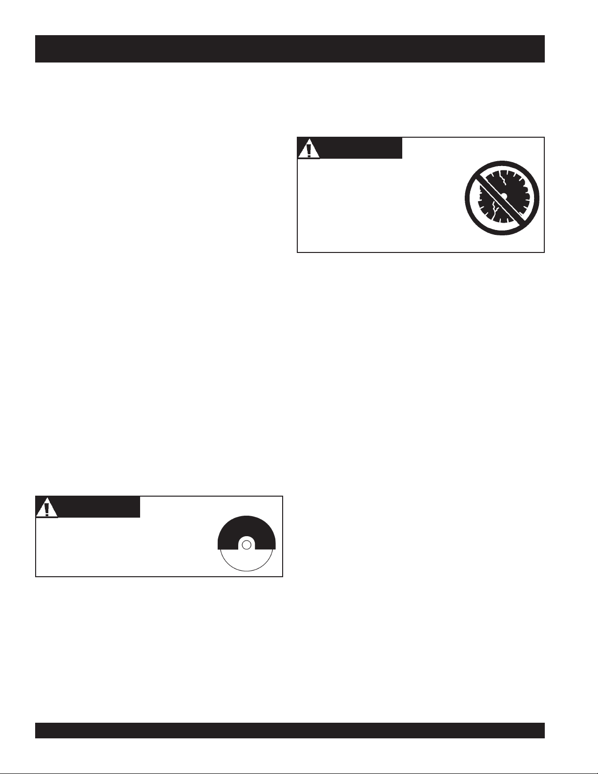
WARNING
ALWAYS inspect diamond blades
before each use. The blade should
exhibit no cracks, dings, or flaws in
the steel centered core and/or rim.
Center (arbor) hole must be
undamaged and true.
Examine blade flanges for damage and excessive wear.
Ensure the cleanliness of the blade before blade is installed.
Blade should fit snugly on the shaft and against the inside/
outside blade flanges.
Ensure the blade is marked with an operating speed greater
than the spindle speed of the saw.
Only cut the material that is specified for the diamond blade.
Read the specifications of the diamond blade to ensure the
proper tool has been matched to the material being cut. The
saw has been engineered for WET CUTTING. Ensure a
WET CUTTING blade is being used and that the water supply
system to the blade is properly functioning and being used.
ALWAYS keep blade guards in place. Exposure of the
diamond blade must not exceed 180 degrees.
Ensure that the diamond blade does not come into contact
with the ground or surface during transportation. DO NOT
drop the diamond blade on ground or surface.
The engine governor is set to permit maximum engine speed
in a no-load condition. Do not tamper with the engine
governor to increase the speed. Increasing the engine speed
could allow the maximum rated spindle speed to be
exceeded, creating an unsafe condition.
■
■
Keep all inexperienced and unauthorized people clear of
the cutting area when operating the saw.
■
Always observe all applicable compulsory regulations
relevant to environmental protection, especially fuel storage,
the handling of hazardous substances, and the wearing of
protective clothing and equipment. Instruct the user as
necessary, or, as the user, request this information and
training.
PAGE 10 — SP 1 SAW CE— OPERATION AND PARTS MANUAL — REV. #3 (06/09/08)
■
Ensure that the blade is mounted for proper operating
direction. (See Figure 4, page 13)
Adhere to the Blade Manufacturer's recommendations on
handling, storage, and safe usage of blades.
Page 11
MQ STREET PRO 1 CE SAW — RULES FOR SAFE OPERATION
Saw Transportation Safety
■
DO NOT use the handle bars and/or front pointer as lifting
points.
■
ALWAYS use ramps capable of supporting the weight of the
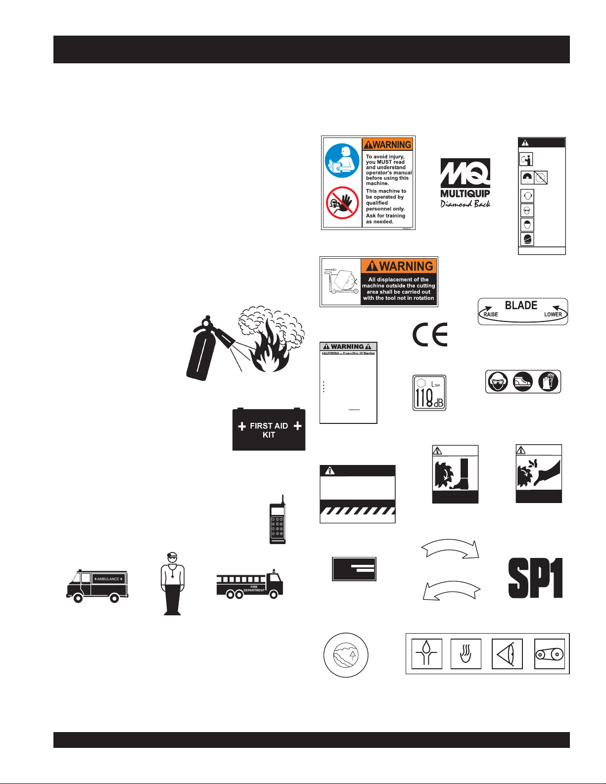
Machine Operation And Safety Decals
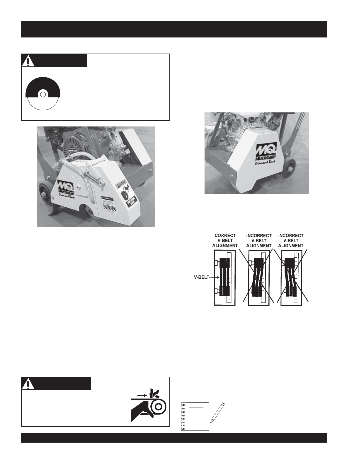
The SP 1 saw is equipped with a number of operation and safety
decals. (Figure 1) Should any of these decals become
unreadable, replacements can be obtained from your dealer.
saw and the operator to load and unload the saw. If the saw
must be lifted, always use two people. Never attempt to lift
the saw by yourself.
■
NEVER attempt to tow the untrailered saw behind a vehicle.
■
DO NOT use on slopes or on extremely uneven surfaces.
■
NEVER tip the engine to extreme angles as it may cause oil
to gravitate into the cylinder head making the engine start
difficult.
■
NEVER transport the saw to or from the job site with the
blade mounted.
EMERGENCIES
■
ALWAYS know the location
of the nearest
extinguisher
■
ALWAYS know the location of the
nearest
.
first aid kit
fire
.
P/N 35137
P/N 25867
Engine exhaust and some of
itsconstituents, andsome dust created
by power sanding, sawing, grinding,
drillingandother constructionactivities
contains chemicalsknown to the State
of California to cause cancer, birth
defects and other reproductive harm.
Someexamples ofthese chemicals are:
Leadfromlead-based paints.
Crystallinesilicafrom bricks.
Cementandother masonryproducts.
Arsenicandchromium fromchemically
treatedlumber.
Yourrisk from these exposures varies,
dependingonhow oftenyoudo thistype
of work.To reduce your exposure to
these chemicals: work in aALWAYS
well ventilated area, and work with
approved safety equipment, such as
dustmasks that are specially designed
tofilter out microscopic particles.
P/N 20525
P/N 25782
P/N 11092
P/N 35167
WARNING!
WARNING
TOPREVENT SERIOUS INJURY
DONOT OPERATE SAW
WITHOUTPROPER TRAINING
&FULL UNDERSTANDING
OFTHE OWNERS MANUAL
WHENOPERATING THIS MACHINE
KEEPALL
GUARDSIN
PLACE
ALWAYSWEAR SAFETY APPROVED
HEARING
PROTECTION
EYEOR FACE
PROTECTION
HEAD
PROTECTION
RESPIRATOR
MASONRYAND CONCRETE
SMI
SAWMANUFACTURING INSTITUTE
P/N 22122-001
P/N 35158
P/N 36099 (ISO Blue)
WARNING!
■
In emergencies
nearest phone or
always
know the location of the
keep a phone on the job site
.
Also know the phone numbers of the nearest
ambulance, doctor,
and
fire department
. This
information will be invaluable in the case of an
emergency.
SP 1 SAW CE— OPERATION AND PARTS MANUAL — REV. #3 (06/09/08) — PAGE 11
CAUTION
When Larger Blade and Guard
is Installed, Belt Drive MUST
Be Changed to Proper Size.
See Owners Manual.
FAILURE TOCOMPLY WITH THE C C AH
JADV EEE AV EEA OIEJGGVCBVVZ
S.M.I. MASONRYAND CONCRETE
SAW MANUFACTURER’SINSTITUTE
P/N 23330-001
MODEL
SERIAL NO.
CONTACT
SERVICE
DEPARTMENT
D
W
E
R
O
P
C
O
D
E
A
T
P/N 13118
KEEP FEET
CLEAR
P/N 25250-001
A
T
T
I
O
O
R
N
P/N 25491
A
T
T
I
O
O
R
N
P/N 25678
P/N 11246
(Sheet-Intl. Stds)
Figure 1. SP 1 Decals
KEEP HANDS
CLEAR
P/N 25249-001
P/N 25783
Page 12
MQ STREET PRO 1 CE SAW — SPECIFICATIONS (SAW)
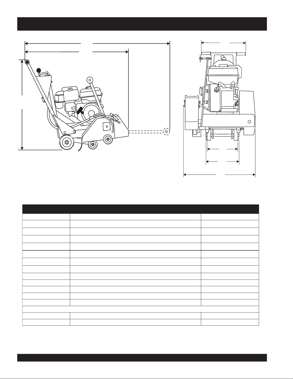
A
Side View
B
C
G
F
E
D
Front View
Figure 2. SP 1 Dimensions
snoitacificepS)81H31EC1PS(1PS.1elbaT
RETTELECNEREFER NOITPIRCSED )mc(NOISNEMID
A
B
C
D
E
F
G
* Vibration (at handle) results with SP1 Saw cutting concrete at a depth of 1-1/2 inches (38.1 mm) with an 18" (45.7 cm)
blade, FULL THROTTLE.
thgieH
)desiaRretnioPtnorF(htgneL
)derewoLretnioPtnorF(htgneLmumixaM
htdiW )mc55(.nI5.12
esaBleehWraeR )mc04(.nI0.71
esaBleehWtnorF )mc4.52(.nI0.01
htdiWraBeldnaH )mc55(.nI5.12
MPReldnipSmumixaM MPR6382
eziSrobrA )mc45.2("0.1
htpeDgnittuCmumixaM )mc87.71("0.7
noitisoPs'rotarepOtaerusserPdnuoS bd8.99
*noitarbiV sm6.21
ssaMgnitarepOmumixaM )gK701(.sbl632
)sdiulfroedalbtuohtiw(ssaMlanimoN )gK79(.sbl412
)mc49(.nI0.73
)mc08(.nI0.23
)mc831(.nI5.45
2-
PAGE 12 — SP 1 SAW CE— OPERATION AND PARTS MANUAL — REV. #3 (06/09/08)
Page 13

MQ STREET PRO 1 CE SAW — SPECIFICATIONS (ENGINE)
)enignE(snoitacificepS.2elbaT
ledoM
epyT
eroB
enignE
leuF
dohteM
ekortSX
tnemecalpsiD)cc983(.ni-uc7.32
tuptuOxaM.M.P.R0063/.P.H0.31
yticapaCknaTleuF
yticapaCliOebuL)retil1.1(
lortnoCdeepS
ADNOH
2TWQ1U093XG/2TWQ1K093XG
elgniS,ekorts4delooc-riA
enignEenilosaG,VHO,rednilyC
.ni5.2X.ni5.3
)mm46xmm88(
sn
ollaG.S.U27.1.xorppA
)sretiL5.6(
enilosaGelibomotuAdedaelnU
rehgihroenatcO68
tqSU61.1
epyTthgiew-ylFlagufirtneC
dohteMgnitratStratSlioceR
noisnemiD
)HxWxL(
yrD
thgieWteN
71x0.51
.ni4.71X7.
)mm344X054X083(
).gK13(sbl4.86
SP 1 SAW CE— OPERATION AND PARTS MANUAL — REV. #3 (06/09/08) — PAGE 13
Page 14

MQ STREET PRO 1 CE SAW — GENERAL INFORMATION
Intended Use
Operate the SP1 Saw, tools and components in accordance
with the manufacturer's instructions. Use of any other tools for
stated operation is considered contrary to designated use. The
risk of such use lies entirely with the user. The manufacturer
cannot be held liable for damages as a result of misuse.
This saw is not intended for dry cutting.
General Information
The MQ Whiteman SP1 series
for
wet
cutting of
These saws have been engineered for general and industrial
flat sawing applications.The reinforced steel box frame design
adds strength necessary to reduce blade vibrations while cutting.
By minimizing blade vibrations the performance of the blade is
enhanced and thus the life of the blade is extended.
Heavy-duty front and rear axles, sturdy oversized wheels, and
industrial undercarriage assembly ensure accurate tracking and
years of reliable use.
Additionally, the general strength-to-weight ratio design of the
frame and chassis assembly provides for optimum weight
distribution to keep the blade running true in the cut. A rugged
spindle bearing assembly ensures minimal flutter and shaft
harmonics providing the most advantageous condition for a
diamond blade at operating speeds.
The SP1 series saw comes equipped with an 18-inch blade guard
and handles Diamond Blade ranging in size from 12-18-inches in
diameter.
An ACME thread, manual raise/lower assembly easily raises and
lowers the blade and locks it into position to ensure a constant depth
cut. All SP1 series saws are equipped with a retractable cutting
guide, oversized roller bearing wheels, industrial spindle bearings,
and a rigid steel frame.
concrete
walk-behind saws
or
asphalt
utilizing Diamond Blades.
are designed
Power Plants
The SP1 saw is classified in the industry as a "low" powered saw.
This classification is particularly useful when selecting the proper
diamond blade for an application.
The SP1 saw is powered by a HONDA GX390 air cooled, 4stroke, single cylnder, OHV gasoline engine rated at 13 HP (9.6
kW) at 3,600 RPM. Blade rotation is V-belt driven. The upper
drive (engine) pulley on the output shaft of the engine connects
to the lower drive (spindle) pulley and thus, the blade, by three
V-Belts. As the engine shaft rotates, so does the blade. The ratio, or
difference between the engine speed and the spindle (blade) speed
is determined by the two different sizes of pulleys used.
Refer to the
regarding engine operation and maintenance practices.
All MQ Whiteman SP1 series saws are designed, engineered
and manufactured with strict adherence to American National
Standards Institute, Inc. (ANSI) guidelines B7.1 and B7.5.
Water System
All SP1 series saws provide a hardy water plumbing system that
evenly distributes water volume and optimum flow rate to both
sides of the blade to keep it cool when cutting. The basic water
system provides a valve that connects to a standard garden hose.
The water is delivered (via a hose) to the saw blade. A water tank
delivery system is optional.
Features
■
Engine Stop Switch conveniently located on handle bar
■
Super-rigid box frame- ensures straight cuts while resisting
warping and blade vibration
■
Rugged roller bearing wheels for long service life
■
Comfortable grip handles
Engine Owner's Manual
for specific instructions
■
Easy cranking for manually raising/lowering the blade to the
desired cutting height
■
Hinged front, lift-up blade guard is designed to provide easy
blade replacement
■
Saw position guide helps ensure straight cuts
■
Water system provides optimum flow and volume of water to
both sides of the blade
■
manually operated wheel clamps help to prevent unwanted
displacement of saw
Figure 3. MQ STREET PRO 1 SAW
PAGE 14 — SP 1 SAW CE— OPERATION AND PARTS MANUAL — REV. #3 (06/09/08)
Page 15
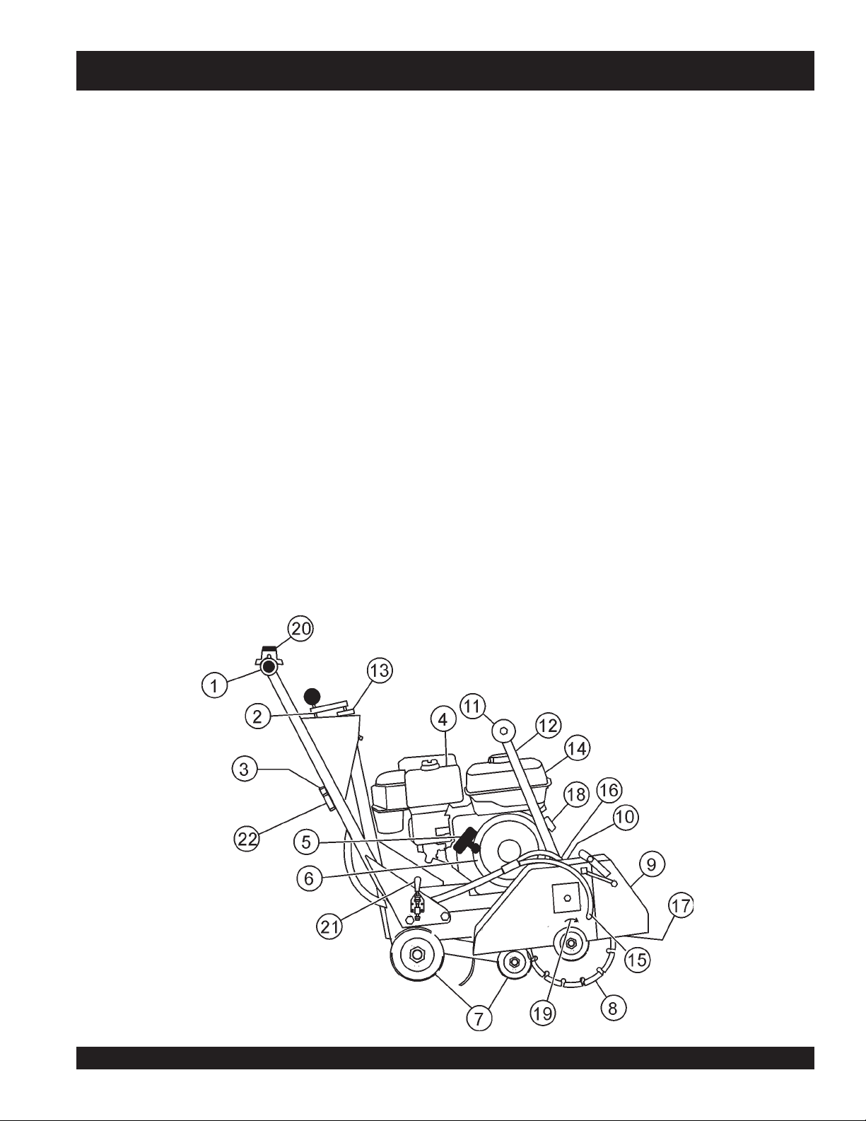
MQ STREET PRO 1 CE SAW — CONTROLS & COMPONENTS
CONTROLS & COMPONENTS
Figures 4 shows the location of the basic controls or components
for the SP 1. Listed below is a brief explanation of each control or
component.
1. Hand Grips/Handlebar – When operating the saw, place
both hands on each grip to maneuver the saw. Replace
hand grips when they become worn or damaged.
2. Handle Lock – Lock blade depth to desired position.
3. Garden Hose Connecter – Connect to water source to
provide blade cooling while cutting concrete or asphalt.
4. Air Filter – Prevents dirt and debris from entering the engine
air intake. Check filter periodically and replace when
necessary.
5. Recoil Starter Handle – Pull to engage and start the
engine.
6. Recoil Starter Assembly – Engages the engine when
the handle is pulled and rewinds the starter rope when the
handle is released.
7. Wheels/Carriage Assembly – Heavy-duty wheels with
permanently sealed ball bearings.
8. Cutting Blade – Use appropriate type blades for cutting
concrete or asphalt.
9. Blade Guard – Covers saw blade and flips up to allow
blade to be changed.
10. Belt Tension Adjuster – Adjusts belt tension.
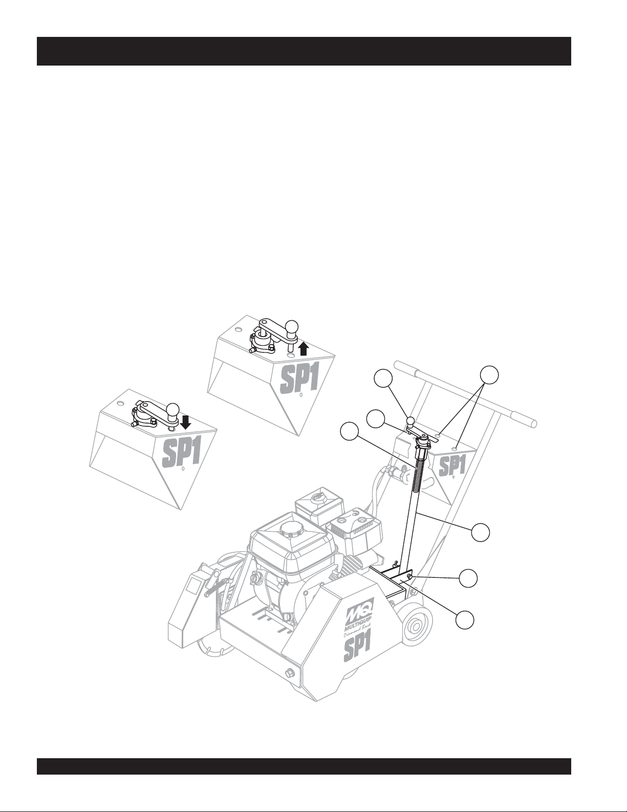
11. Front Pointer – Front pointer wheel assists in straight
tracking.
12. Front Pointer Arm – Stows up for storage and pivots down
for use.
13. Cutting Depth Adjuster – turn operating crank clockwise
or counter-clockwise to adjust the cutting depth up or down.
14. Fuel Tank – Use unleaded gasoline. Do not overfill.
15. Blade Coolant System – Provides cooling water to blade
during cutting operations.
16. V-Belt Cover – Remove this cover to gain access to the Vbelts. NEVER operate the saw with this cover removed.
17. Spindle Grease Zerks – Conveniently located for
lubrication.
18. On/Off Switch (On Engine) – Turn to the "ON" position to
allow engine to be started and turn to the "OFF" position to
shut the engine off.
19. Tool Rotation – Rotational direction of tool (blade) during
operation.
20. Engine Stop Switch (On Handlebar) – Toggle in either
direction to stop the engine.
21. Wheel Clamp – Move handle down making contact with
wheel to avoid unwanted rolling movement. Lift handle to
release.
Figure 4. SP 1 Components
22. Water Valve – Rotate handle to turn water supply on or off.
SP 1 SAW CE— OPERATION AND PARTS MANUAL — REV. #3 (06/09/08) — PAGE 15
Page 16
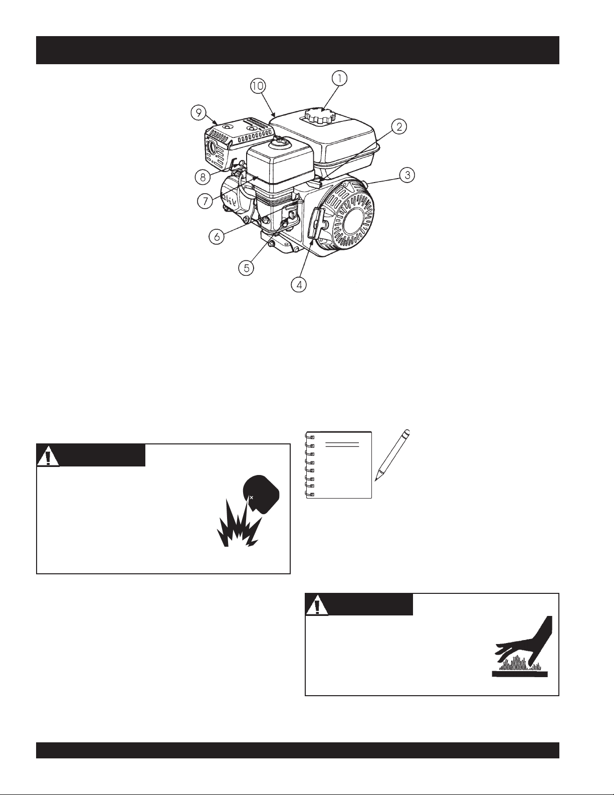
BASIC ENGINE
MQ STREET PRO 1 CE SAW — BASIC ENGINE
Figure 5. Engine Controls and Components
Initial Servicing
The engine (Figure 5) must be checked for proper lubrication and
filled with fuel prior to operation. Refer to the manufacturers engine
manual for instructions & details of operation and servicing.
1. Fuel Filler Cap – Remove this cap to add unleaded
gasoline to the fuel tank. Make sure cap is tightened
securely. DO NOT over fill.
DANGER
Adding fuel to the tank should be done only
when the engine is stopped and has had an
opportunity to cool down. In the event of a
fuel spill, DO NOT attempt to start the engine
until the fuel residue has been completely
wiped up, and the area surrounding the
engine is dry.
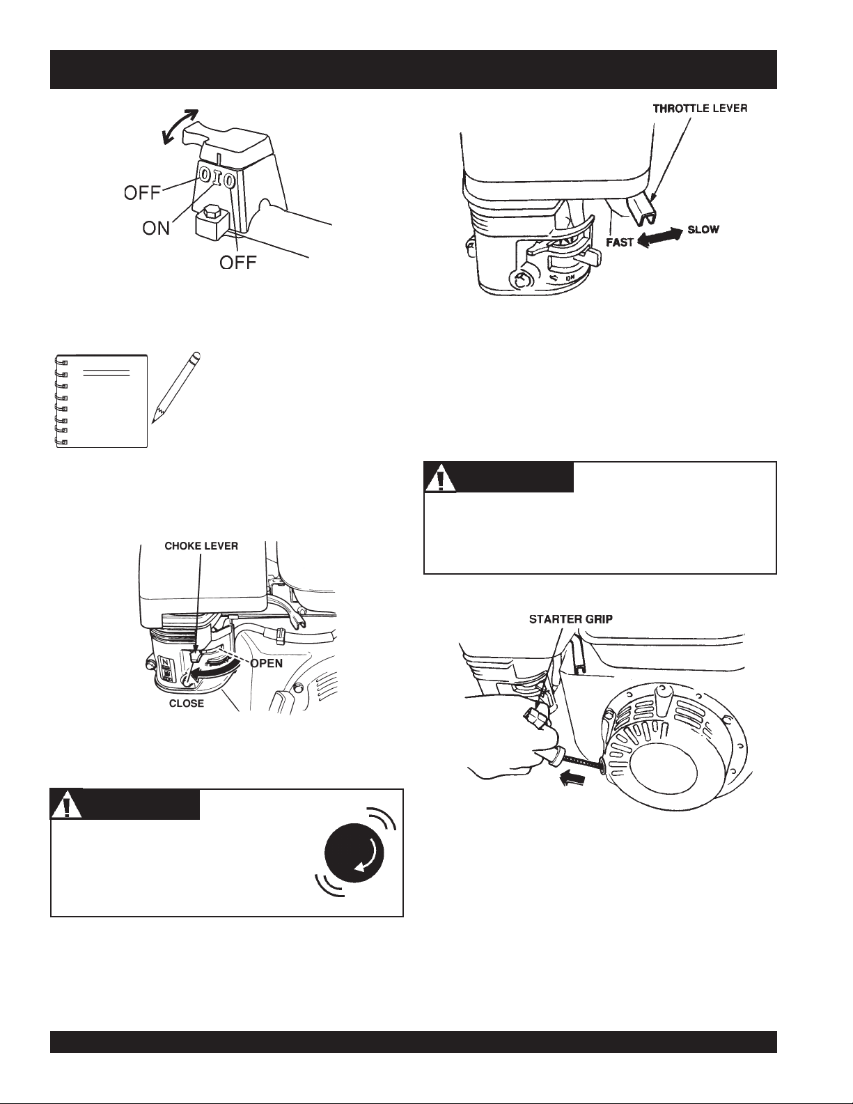
2. Throttle Lever – Used to adjust engine RPM speed (lever
advanced forward
FAST
).
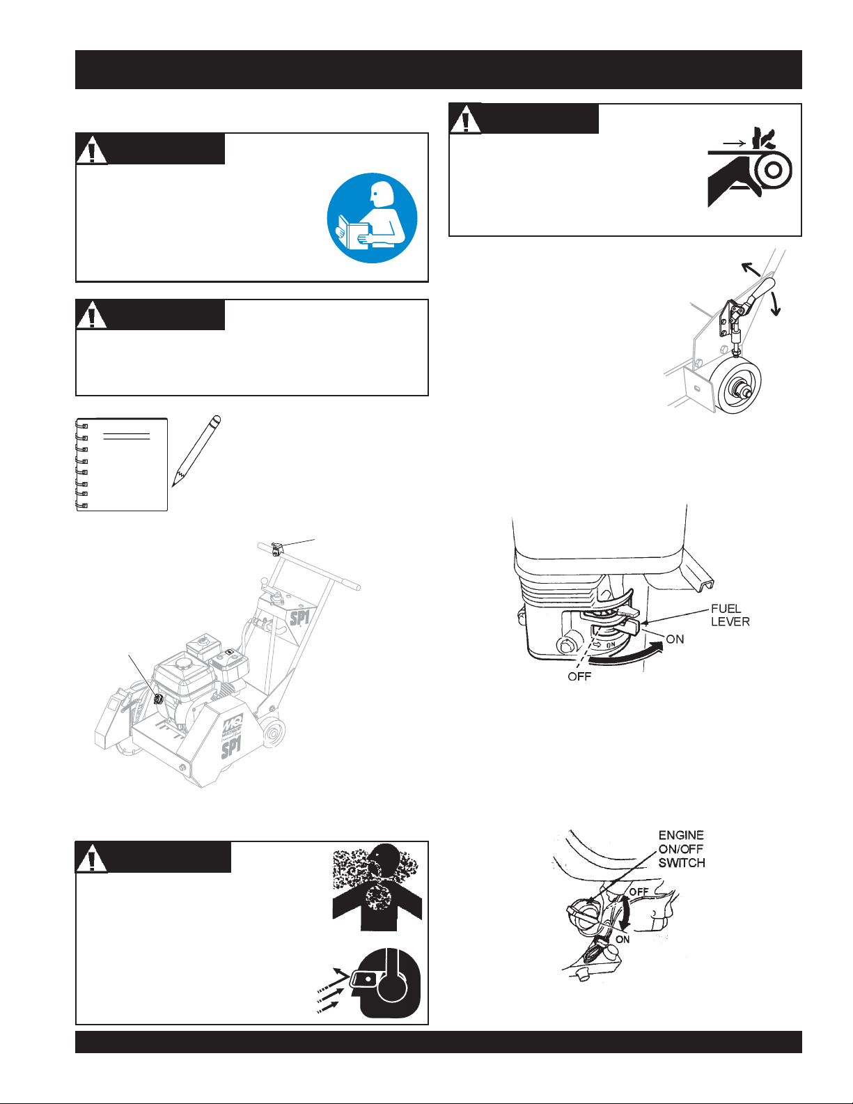
3. Engine ON/OFF Switch – ON position permits engine
starting, OFF position stops engine operations.
4. Recoil Starter (pull rope) – Manual-starting method. Pull
the starter grip until resistance is felt, then pull briskly and
smoothly.
SLOW
, lever back toward operator
6. Choke Lever – Used in the starting of a cold engine, or in
cold weather conditions. The choke enriches the fuel
mixture.
7. Air Cleaner – Prevents dirt and other debris from entering
the fuel system. Remove wing-nut on top of air filter
cannister to gain access to filter element.
NOTE
8. Spark Plug – Provides spark to the ignition system. Clean
spark plug once a month.
9. Muffler – Used to reduce noise and emissions.
Engine components can generate extreme heat.
To prevent burns, DO NOT touch these areas
while the engine is running or immediately after
operating. NEVER operate the engine with the
muffler removed.
Operating the engine without an air
filter, with a damaged air filter, or a
filter in need of replacement will
allow dirt to enter the engine, causing
rapid engine wear.
WARNING
5. Fuel Valve Lever – OPEN to let fuel flow, CLOSE to stop
the flow of fuel.
PAGE 16 — SP 1 SAW CE— OPERATION AND PARTS MANUAL — REV. #3 (06/09/08)
10. Fuel Tank – Holds unleaded gasoline. For additional
information refer to engine owner's manual.
Page 17
MQ STREET PRO 1 CE SAW — PREPARATION/PRE-INSPECTION
PREPARATION / PRE-INSPECTION
1. Read and fully understand this manual,
the safety intructions in particular, and
the engine manufacturer's manual
supplied with the saw.
2. Select the correct blade for each application. Refer to the
Blades and Blade Placement sections on pages 17 through
19 for further information.
3. Check blade for wear or damage.
Handle all blades with care and
ALWAYS replace a damaged blade.
4. Clean the
particularly the engine cooling air inlet,
carburetor and air cleaner.
5. Check the air filter for dirt and dust. Replace the air filter if it
is found to be dirty.
6. Check carburetor for external dirt and dust. Clean with dry
compressed air.
7. Check fastening nuts and bolts for tightness.
8. Ensure a suitable water supply is available, hooked up, and
used. (connected via garden hose or with an optional water
tank supply system).
saw,
removing dirt and dust,
NOTE
Reference manufacturer engine
manual for specific servicing
instructions.
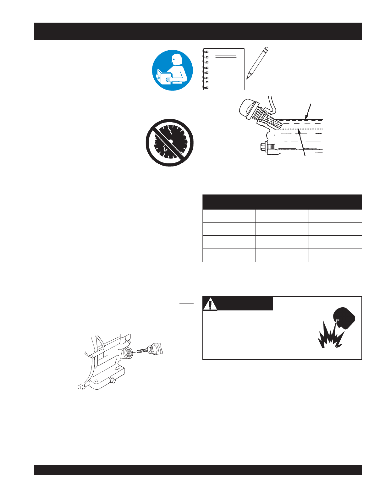
UPPER LIMIT
LOWER LIMIT
Figure 7. Engine Oil Dipstick (Oil Level)
epyTliO.3elbaT
nosaeS erutarepmeT epyTliO
remmuS rehgiHroC°52 03-W01EAS
llaF/gnirpS C°01~C°52 02/03-W01EAS
retniW rewoLroC°0 01-W01EAS
Engine Oil Check
1. To check the engine oil level, place the saw on secure level
ground with the engine stopped. The frame platform
be level
2. Remove the filler dipstick from the engine oil filler hole
(Figure 6) and wipe it clean.
to accurately check the engine oil.
must
Fuel Check
Motor fuels are highly flammable and can
be dangerous if mishandled. DO NOT
smoke while refueling. DO NOT attempt to
refuel the saw if the engine is
running
1. Remove the gasoline cap located on top of fuel tank.
2. Visually inspect to see if fuel level is low. If fuel is low, replenish
with unleaded fuel.
Figure 6. Engine Oil Dipstick (Removal)
3. When refueling, be sure to use a strainer for filtration. DO
3. Insert and remove the dipstick without screwing it into the filler
neck. Check the oil level shown on the dipstick.
4. If the oil level is low (Figure 7), fill to the edge of the oil filler
hole with the recommended oil type (Table 3).
NOT top-off fuel. Wipe up any spilled fuel.
Warning
.
hot!
or
SP 1 SAW CE— OPERATION AND PARTS MANUAL — REV. #3 (06/09/08) — PAGE 17
Page 18
MQ STREET PRO 1 CE SAW — PREPARATION/PRE-INSPECTION
Guards And Covers
WARNING
NEVER operate the saw without blade
guards and covers in place. DO NOT
operate with the front of the blade guard
raised. The blade exposure cannot exceed
180 degrees during operation. Adhere to
the safety guidelines or other applicable
local regulations.
Figure 8. Blade Guard
V-belt Alignment and Tensioning
This saw is equipped with premium V-belts that have been
aligned and tensioned by factory personnel. The V-belt must be
aligned and tensioned for proper operation of the saw.
Use the following procedure to check the alignment of V-belt:
1. Remove the bolts that secure the V-belt cover (Figure 9) to
the saw frame.
Figure 9. V-Belt Cover
2. Check uniform parallelism (Figure 10) of V-belt and pulley
(sheaves). Use a straight-edge or machinist's square against
both pulleys and adjust both pulleys until equally aligned.
CHECK the following on the blade guard (Figure 8):
■
Ensure the capacity of the blade guard is correct for an 18"
Diamond Blade.
■
Check that the guard is bolted firmly upon the saw frame.
■
Check that the spring tensioned front cover of the guard is
firmly seated with the rear section of the guard and there are
no gaps. NEVER lift the blade guard while engine is running.
ENSURE the V-belt Cover is in place and securely fastened
during operation of the saw (Figure 8).
3. Check V-belt tension by using a tension meter (3.0 lbs./
V-Belt Check
A worn or damaged V-belt can adversely affect the performance
of the saw. If a V-belt is defective or worn, replace ALL the Vbelts. V-belts should always be replaced in sets.
4. DO NOT over or under tighten the V-belt. Severe damage
WARNING
NEVER attempt to check the V-belt with the
engine running. Severe injury can occur.
Keep fingers, hands, hair, and clothing away
from all moving parts.
Figure 10. Pulley Alignment
1.36Kg) against the inside belt at a mid point between the
two pulleys, or by deflecting the center belt at a mid point
3/16" (5 mm).
can occur to the saw and engine crankshaft if the belt is
over-tensioned. A decrease of power to the blade and poor
performance will result if the belt is under-tensioned (loose
on pulleys).
NOTE
V-belt alignment must be rechecked after
adjusting belt tension.
PAGE 18 — SP 1 SAW CE— OPERATION AND PARTS MANUAL — REV. #3 (06/09/08)
Page 19
MQ STREET PRO 1 CE SAW — BLADES
SPECIFIC TOOLS TO BE USED
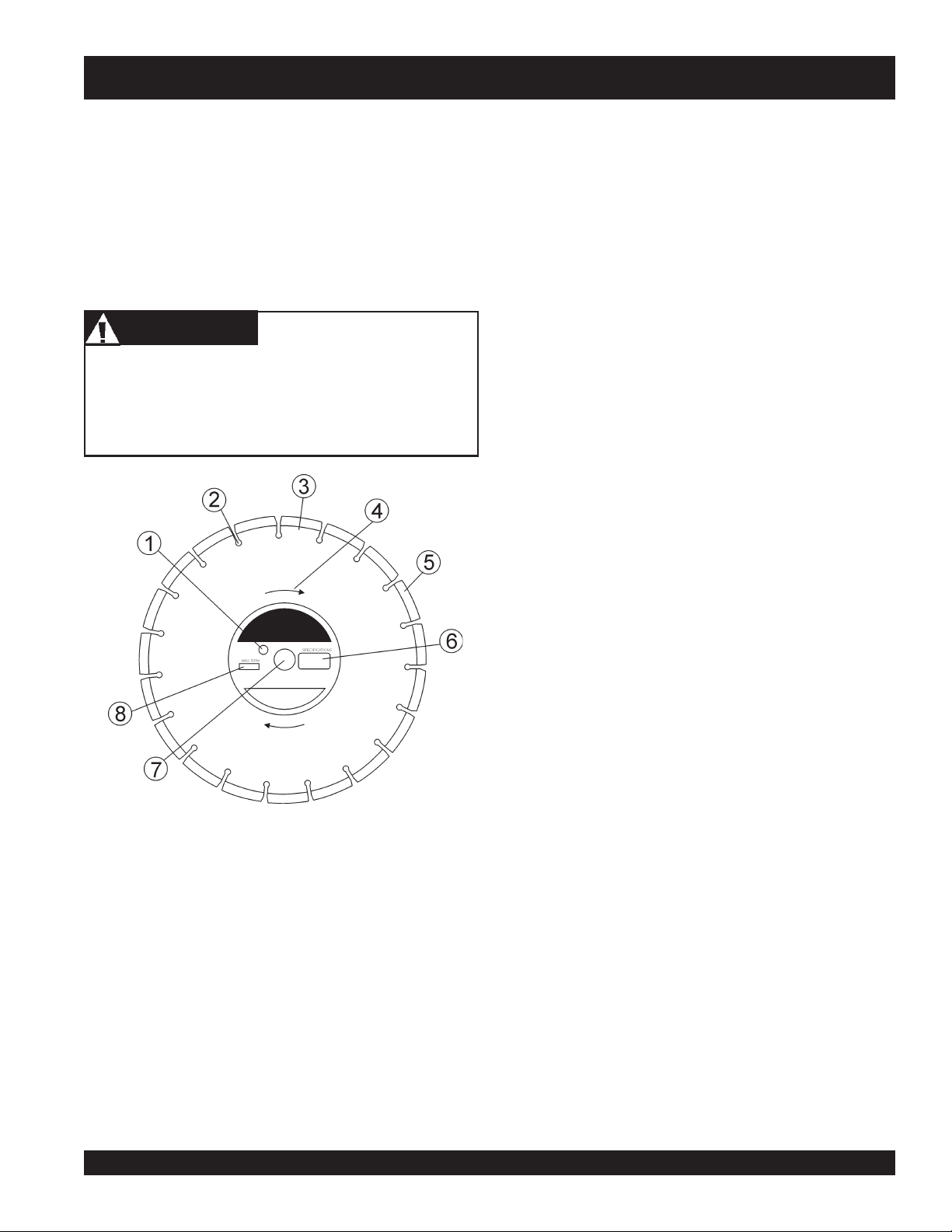
1. Drive Pin Hole – A commonly located hole on the diamond
This saw is to use tools (blades) as follows:
Steel Core Segmented or Continuous Diamond Rim
Cutting Wheel.
Any other type of tool is not to be used. See Table 4 for specific
blade usage for material.
WARNING
Failure to thoroughly inspect the diamond blade (Figure 11)
for operational safety could result in damage to the blade or
the saw, and may cause injury to the user or others in the
operating area. Discard damaged or worn blades and
replace with fresh blade.
2. Stress Relief Holes (Gullets) –
3. Edge Of The Steel Core – Check the diameter edge for
4. Directional Arrow – Check to ensure that the blade is
blade core that prevents operational blade slippage
between the inner & outer blade flanges (collars). Inspect
the diameter of the hole to ensure there is no distortion,
and that a snug fit develops between the hole and drive
pin.
Check the steel core for
cracks that may have propagated from the slots and/or
gullets. Cracks indicate extreme fatigue failure and if sawing
continues, catastrophic failure will occur.
discoloration (blue oxidation) indicating an overheating
condition caused by insufficient cooling water/air.
Overheating of blades may lead to loss of core tension
and/or increase the possibility for blade failure. Check to
make sure the steel core’s width is uniform about the rim of
the blade, and not succumbing to an “under cutting”
condition brought about by highly abrasive material or
improper under cutting core protection.
oriented properly on the spindle for sawing. Reference the
directional arrow on the blade and place it so the direction
of rotation “downcuts” with the turn of the shaft.
Figure 11. Diamond Blade
5. Diamond Segment or Rim – Ensure there are no cracks,
dings, or missing portions of the diamond segment/rim. DO
NOT
use a blade that is missing a segment or a portion
the rim
of
cause damage to your saw, and injury to the user or others
in the operating area.
. Damaged and/or missing segments/rims may
6. Specifications – Ensure that the blade specifications, size,
and diameter properly match up to the sawing operation.
Wet blades must have water to act as a coolant. Utilizing a
diamond blade not matched properly to the task may result
in poor performance and/or blade damage.
7. Arbor Hole – It is essential that the arbor hole diameter
properly matches the shaft arbor, and that it is free from
distortions. Correct blade flanges (collars) must be used.
The inside face of the flanges must be clean & free of debris.
An out of round arbor condition will cause damage to the
blade and the saw.
8. MAX RPM – This RPM reference is the maximum safe
operating speed for the blade selected. NEVER exceed
the max RPM on the diamond blade. Exceeding the MAX
RPM is dangerous, and may cause poor performance and
may damage the blade. All blades used must be designed
for the maximum spindle RPM.
SP 1 SAW CE— OPERATION AND PARTS MANUAL — REV. #3 (06/09/08) — PAGE 19
Page 20
MQ STREET PRO 1 CE SAW — BLADE PLACEMENT
NOITCELESEDALBDNAGNITSILLAIRETAM.4elbaT
lairetaMedalB
etercnoCderuCedalBetercnoCderuC
etercnoCneerGedalBete
tlahpsAedalBtlahpsA
etercnoCrevotlahpsAedalBetercnoC/tlahpsA
seirotcarfeR,yrnosaM,kcirB,kcolBeda
enotS,cimareC,eliTedalBeliT
Diamond Blades
Selecting the diamond blade TYPE and GRADE defines how
the blade will perform both in cutting speed and blade life.
Selection of the proper diamond blade consists of:
z
Material to be Cut
z
Type of Saw Being Used
z
Horsepower of Saw
z
Hardness Characteristics of the Material
z
Performance Expectations
Factors for sawing economy:
z
Type of Blade
z
Depth of Cut
z
Sawing Speed
z
Characteristics of the Material Being Cut
Blade Speed
A diamond blade’s performance is directly connected to specific
peripheral (rim) speeds.
The following shaft rotational speeds have been factory set to
ensure optimum blade performance.
z
SP1 18” Capacity - 2,836 RPM.
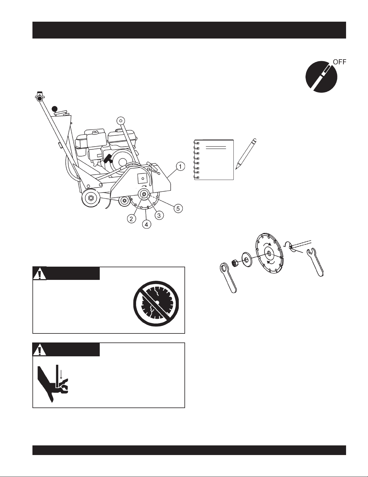
BLADE PLACEMENT
1. Engine OFF - Set the ENGINE ON/OFF switches to the
"OFF" position to prevent accidental starting.
2. Blade Guard - Pivot the blade guard front cover all the way
back. The guard tension spring will keep the front cover in
position.
3. Blade Hex Nut - Unscrew the spindle nut (right side loosens
clockwise and tightens counter-clockwise while the left side
loosens counter-clockwise and tightens clockwise. DO NOT
overtighten the nut (approximately 45-50 ft. lb/61-68 N/m)
when finalizing the assembly.
4. Outside Blade Flange (Collar) - Ensure that the outside
blade flange is placed flush against the diamond blade.
The inside surface of the flange must be free of debris and
permit a tight closure on the surface of the blade core.
WARNING
5. Diamond Blade - Ensure that the proper diamond blade
Operating saw blades at rotational speeds
greater than those specified by the manufacture can cause blade damage, and may
injure the user or others in the operating
area.
has been selected for the job. Pay close attention to the
directional arrows on the blade. The blade's operating
directional arrows must point in a "down-cutting" direction
to perform correctly. When placing the blade onto the spindle,
ensure the arbor hole of the blade matches the diameter of
the shaft.
rcnoCneerG
lByrnosaM
WARNING
Failure to thoroughly inspect the
diamond blade for operational safety
could result in damage to the blades
or the saw and may cause injury to
the user or others in the operating
area.
PAGE 20 — SP 1 SAW CE— OPERATION AND PARTS MANUAL — REV. #3 (06/09/08)
Page 21
MQ STREET PRO 1 CE SAW — BLADE PLACEMENT
6. Inner Flange (Collar) - This flange is fixed upon the spindle.
The inside surface of the flange must be free of debris and
permit a tight closure on the surface of the blade.
Blade Removal and Replacement
1. Set the ENGINE ON/OFF switches to
the "OFF" position to prevent
accidental starting.
2. Place the saw on a stable level working
surface.
3. Ensure the blade is raised and the raise/lower crank is locked
into position.
When removing or installing a
NOTE
4. Lift up the blade guard cover to gain access to the blade.
diamond blade, please note that the
blade retaining nuts are left and righthand threaded.
Figure 12. Tool (Blade) Placement
WARNING
Incorrectly installed blades can
cause damage to the blade or
equipment or cause injury due to
breakage.
WARNING
Dropping or forcing the blade onto the
cutting surface can severely damage the
diamond blade and may cause serious
damage to the saw and bodily harm.
Figure 13. Tool (Blade) Locking Wrenches
5. Use the provided blade nut and spindle locking wrenches
to remove and install the blade. (Figure 13)
6. Unscrew the spindle nut (right side loosens clockwise and
tightens counter-clockwise while the left side loosens
counter-clockwise and tightens clockwise). DO NOT
overtighten the nut (approximately 45-50 ft. lb/61-68 N/m)
when finalizing the assembly.
SP 1 SAW CE— OPERATION AND PARTS MANUAL — REV. #3 (06/09/08) — PAGE 21
Page 22
MQ STREET PRO 1 CE SAW — RAISE/LOWER AND DEPTH STOP
Raise/Lower and Depth Stop
The saw is equipped with a Raise/Lower and Depth Stop
Assembly that is supported by the following components. (Figure
14)
1. Adjusting Hand Crank Assembly
2. Raise/Lower Acme Screw
3. Jack Arm
4. Wheel Base Assembly
5. Jackshaft Pin
6. Lock Positions
Setting the Depth Stop
1. Lift the Adjusting Hand Crank to unlock (disengage) the
Depth Stop.
2. Rotate the crank to raise or lower the blade to the desired
depth.
3. Lower the crank into one of the lock position holes (Item 6).
Unlocked
Position
Locked
Position
1
6
6
2
3
5
4
Figure 14. Cutting Depth - Raise/Lower System
PAGE 22 — SP 1 SAW CE— OPERATION AND PARTS MANUAL — REV. #3 (06/09/08)
Page 23
MQ STREET PRO 1 CE SAW — INITIAL START-UP
INITIAL START-UP
CAUTION
DO NOT attempt to operate the saw until
this manual has been read and
thoroughly understood. Engine operating
steps may vary. See included engine
manufacturer's operating manual.
1. Keep Wheel Clamp applied (lever DOWN)
CAUTION
Ensure the work area is clear of tool, debris, and unauthorized
people.
The Engine Stop Switch located on the
NOTE
handlebar (Figure 15) serves both as
an Emergency Engine Shut-Off and
2. Ensure the diamond blade has been mounted correctly and
as the primary ON/OFF switch. This
allows the operator to shutdown the
3. Place the
saw safely away from moving parts.
CAUTION
NEVER place hands or feet inside the
belt guard or blade guard while the
engine is running. ALWAYS shut the
engine down before performing any kind
of maintenance service on the saw
until completely ready for cutting operation.
Figure 16. Wheel Clamp
that it is raised above the surface you are about to saw.
fuel valve lever
(Figure 17) to the "ON" position.
ENGINE STOP SWITCH
(Emergency Stop
and Primary ON/OFF)
ENGINE STOP
SWITCH
(Secondary ON/OFF)
Figure 15. Engine Stop Switches
WARNING
NEVER operate the saw in a confined area
or enclosed structure that does not provide
free flow of air
ample
.
Figure 17. Engine Fuel Valve Lever
4. Place the
ENGINE ON/OFF switch
(Figure 18) in the "ON" position. Place the
located on the HANDLEBARS (Figure 15) in the
switch
"ON" (center) position.
located on the ENGINE
ENGINE ON/OFF
ALWAYS wear approved eye and hearing
protection while operating the saw.
SP 1 SAW CE— OPERATION AND PARTS MANUAL — REV. #3 (06/09/08) — PAGE 23
Figure 18. Engine ON/OFF Switch (On Engine)
Page 24
MQ STREET PRO 1 CE SAW — INITIAL START-UP
Figure 19. Engine Stop Switch (Handlebar)
The CLOSED position of the
choke lever enriches the fuel
mixture for starting a COLD engine.
NOTE
The OPEN position provides the
correct fuel mixture for normal
operation after starting, and for
restarting a warm engine.
Figure 21. Throttle Lever
7. Grasp the starter grip (Figure 22) and slowly pull it out. The
resistance becomes the hardest at the compression point.
Pull the starter grip briskly and smoothly for starting.
5. Place the
position.
Choke Lever
Figure 20. Choke Lever
(Figure 20) in the "
CAUTION
The engine speed has been set at the
factory. Changing the governor speed
could damage the blade and/or the saw.
CLOSED
"
CAUTION
DO NOT pull the starter rope all the way to the end. DO NOT
release the starter rope after pulling. Allow it to rewind as
soon as possible.
Figure 22. Starter Grip
8. If the engine has started, slowly return the choke lever
(Figure 21) to the
started repeat steps 1 through 7.
"OPEN"
position. If the engine has not
6. Rotate the
and
engine governor speed is factory set to ensure optimum
blade operating speeds.
throttle lever
slow
for starting. All sawing is done at
PAGE 24 — SP 1 SAW CE— OPERATION AND PARTS MANUAL — REV. #3 (06/09/08)
(Figure 21) halfway between
full throttle
fast
. The
9. Before the saw is placed into operation, run the engine for
several minutes. Check for fuel leaks, and noises that could
be associated with loose guards and/or covers.
Page 25
MQ STREET PRO 1 CE SAW — OPERATION
OPERATION
WARNING
ALWAYS cut with the saw at FULL THROTTLE. Attempting
to cut with the saw at less than full throttle could cause the
blade to bind or stop abruptly in the slab resulting in serious
injury to the operator or others in the area.
1. Start the engine as described in the previous section. Rotate
WARNING
ALWAYS keep clear of
operating this equipment.
rotating
or
moving
parts while
2. Release Wheel Clamps by pulling levers UP.
CAUTION
Ensure the cutting area is clear of tools, debris, and
unauthorized people.
CAUTION
The Engine Stop Switch located on the
handlebar (Figure 19) serves both as
NOTE
the throttle lever (Figure 21) toward full throttle. Ensure water
supply system is in operation. Tur n valve to start flow of water.
(For water tank option, see page 27.)
unlock position
an Emergency Engine Shut-Off and
as the primary ON/OFF switch. This
allows the operator to shutdown the
saw safely away from moving parts.
lock position
DO NOT try to cut faster than the blade will allow. Cutting too
fast will cause the blade to rise up out of the cut. Improper
cutting rate can decrease the life of the engine and blades.
CAUTION
Engine components and the blade can get
EXTREMELY HOT! during operation.
ALWAYS allow the engine and blade to cool
before handling or servicing.
CAUTION
Whenever the saw is not in operation or being moved or
transported, apply the wheel clamp brakes to prevent
unwanted displacement.
NOTE
Mark the cutting line clearly and always
saw in a STRAIGHT LINE ONLY.
3. To begin sawing, use the raise/lower crank handle on the
console to lower the rotating blade allowing it to cut to the
preset depth.
4. When blade has reached full cutting depth, slowly walk
behind the saw at a rate that will allow the engine to operate
without losing optimum RPM.
5. When the end of the cut has been reached, use the raise/
lower crank on the console to raise the blade out of the cut.
6. When cutting is complete, turn the engine OFF using the
ENGINE STOP TOGGLE SWITCH on the handlebars, and
wait for the blade to stop rotating.
7. Set the engine ON/OFF switch to the OFF position.
8. Place the water valve in the OFF position (as required).
9. Push the Wheel Clamp Levers downward to apply braking
pressure to the wheels (Figure 23).
Figure 23. Wheel Clamp
SP 1 SAW CE— OPERATION AND PARTS MANUAL — REV. #3 (06/09/08) — PAGE 25
Page 26

MQ STREET PRO 1 CE SAW — OPERATION
Restarting After Intervention
If cutting is interrupted where the engine stops or is turned off
while the blade is still in the cut:
a. Turn Engine Off switches to "OFF"
b. Raise the blade out of the cut
c. Restart the engine as described in the previous
section.
CAUTION
The only acceptable method for freeing a stuck blade is to
remove the saw from the stuck or pinched blade. DO NOT
try to get the blade unstuck using the Raise/Lower system
or by lifting the saw by the lifting bale, etc.
If cutting is interrupted where the blade is stuck in the cut:
a. Turn Engine Off switches to "OFF".
b. Remove the blade guard.
c. Remove blade mounting bolt and outer flange.
d. Maneuver the saw away from the stuck blade.
e. A parallel cut made next to the blade may be necessary
to free it.
f. Once the blade is freed inspect the blade for damage;
discard if damaged.
e Ensure an undamaged, useable blade is installed on
the saw before cutting is resumed with that saw.
PAGE 26 — SP 1 SAW CE— OPERATION AND PARTS MANUAL — REV. #3 (06/09/08)
Page 27

MQ STREET PRO 1 CE SAW — MAINTENANCE
MAINTENANCE
See the engine manual supplied with your
machine for appropriate engine
maintenance schedule and troubleshooting
guide for problems.
General maintenance practices are crucial to the
performance and longevity of your saw. The extreme
environments of sawing operations require routine
cleaning, lubrication, belt tensioning, and inspection for wear
and damage
The following procedures devoted to maintenance can prevent
serious saw damage or malfunctioning.
ALWAYS allow the engine to cool before
servicing. NEVER attempt any maintenance
work on a
Saw Blade Removal and Installation
See page 19.
General Cleanliness
Clean the machine daily. Remove all dust and slurry build up.
If the saw is steam cleaned, ensure that lubrication is accomplished AFTER steam cleaning operations.
DANGER
Some maintenance operations may require
the engine to be run. Ensure that the maintenance area is well ventilated. Exhaust contains poisonous carbon monoxide gas that
can cause of unconsciousness and may result in DEATH.
WARNING
Before servicing or inspection, ALWAYS
park the saw on a level surface with the
blade removed, and the handlebar Engine ON/OFF switch & Engine ON/OFF
switch in “OFF” position.
Chassis Lubrication
■
Spindle Bearings - Two zerk fittings are located up under
the lower-front of the saw. Lubricate before daily use.
Use a good quality extreme pressure grease. Check and
lubricate more often if unit is under heavy use. Do not
overfill bearings. Overfilling can damage the grease seals.
This can result in bearing exposure to dirt and
contaminants which can then shorten the life of the
bearings. Excess grease can also drip onto the cutting
surface.
Drive Belt
Refer to page 16 of this manual for Drive Belt adjustment
procedures and Removal and Replacement procedures.
CAUTION
hot!
engine.
CAUTION
ALWAYS ensure that both ENGINE ON/
OFF switches (on the handlebar and on
the engine) are in the "OFF" position, and
that the spindle has COMPLETELY
STOPPED ROTATING before performing
any of the the following operations:
■
REMOVING
■
ADJUSTING
■
LUBRICATING
■
REMOVING
■
INSPECTING, ADJUSTING, OR
REPLACING
ANY
engine part
■
REMOVING
or
INSTALLING
front or rear pointers
any components
engine mounting bolts
drivebelt, spindle, spindle bearings or
blade or belt guards
SP 1 SAW CE— OPERATION AND PARTS MANUAL — REV. #3 (06/09/08) — PAGE 27
blades
General Engine Care
Engine check:
Check daily for any oil and/or fuel leakage, thread nut & bolt
tightness, and overall cleanliness.
Engine air filter:
Replace air filter if dirty. See Engine Owner’s Manual for
detailed information.
Engine oil:
Check daily. Inspect with blade removed and saw frame
level on a level surface. Keep the oil clean, and at the proper
servicing level (Figure 7). DO NOT OVERFILL! SAE 10W-
30 of SG is recommended for general use.
Page 28

MQ STREET PRO 1 CE SAW — MAINTENANCE
Engine oil change:
Change engine oil the first month or 20 hours of operation. Then
every 3 months/or 50 HOURS of operation. See Engine Owner’s
Manual for detailed information.
Drain the used oil while the engine is warm by the following
method:
Refer to Figure 24.
1. Place an oil pan or suitable container below the engine drain
plug to catch the used oil.
2. Remove the filler cap/dipstick and the drain plug.
3. Drain the oil completely and reinstall the drain plug. Ensure
the drain plug is tightened securely.
4. Make sure the engine is in a level position and fill to the outer
edge of the oil filler hole with the recommended oil. (See
Table 3.) Engine oil capacity is 1.16 US quart (1.1 liter).
5. Screw in the filler cap/dipstick securely.
Engine tank & strainer:
Clean every year/or 300 hours.
Fuel line:
Replace every two years/or as necessary.
Spark plug:
Clean/adjust every 6 months/or 100 hours. Replace every
year/ or 300 hours.
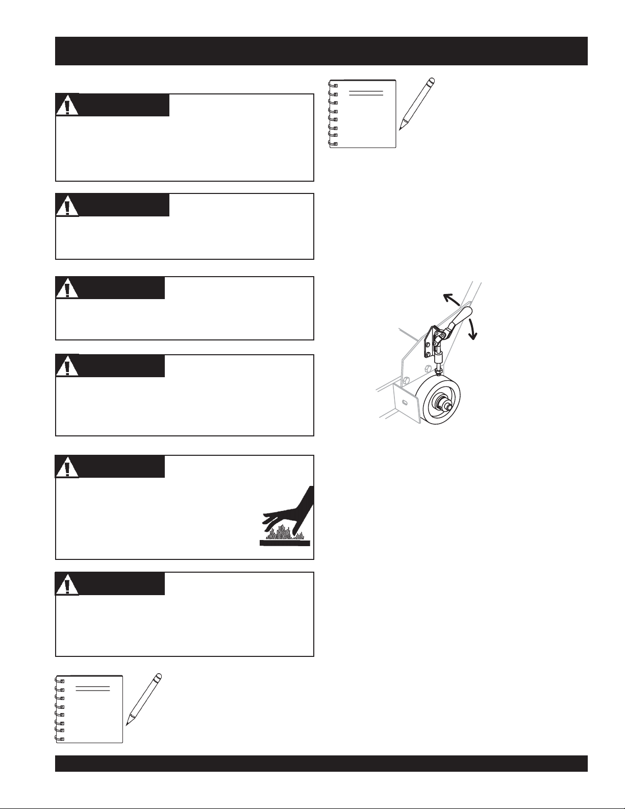
Front Pointer Adjustment
The front pointer wheel has been set at the factory. Use these
procedures only if the pointer is suspect of being out of alignment.
1. Chalk out a straight line on the prepared slab or cutting
surface.
2. Use a straight-edge or level by placing it flat against the blade.
3. Adjust the front pointer wheel so it just touches the side of the
straight-edge or level.
CAUTION
Running the engine with a low oil level can cause engine
damage.
Dispose of used oil properly. DO NOT
NOTE
environmental rules and regulations required in your area
concerning the disposal of hazardous waste such as used oil and
oil filters.
pour used oil on the ground, down a
drain, or throw in the trash. Used oil
can generally be taken to your local
recycling center or service station for
reclamation. Follow all required
4. Remove the straight-edge or level.
5. Position the front pointer and blade directly over the chalk
line.
6. Start the saw and lower the blade onto the chalk line.
7. Begin cutting and make sure the blade follows the chalk line
as closely as possible.
8. The pointer should follow the chalk line as well. If it does not,
adjust the pointer by loosening then tightening the jam nuts
on the pointer until the pointer follows the same path as the
blade.
Figure 24. Engine Oil Change
PAGE 28 — SP 1 SAW CE— OPERATION AND PARTS MANUAL — REV. #3 (06/09/08)
Page 29

MQ STREET PRO 1 CE SAW — OPTIONAL WATER TANK
WATER TANK KIT (OPTION)
An optional water tank kit is available for use with the SP1 Saw.
The following steps are instructions for the assembly of the kit
onto your SP1 Saw.
CAUTION
Make certain all bolts securing the kit to the saw are tight
before operating the saw.
CAUTION
DO NOT use a water tank larger than 5 gallons (18.95 liters)
with this kit.
While the optional water tank kit is
excellent for short-run cutting
NOTE
operations, the use of a pressurized,
continual water source may be
preferred for longer or sustained
cutting.
5. After determining the correct spacer length, place the spac-
ers (item 12, Figure 25) betweem the engine block and the
tank shelf bracket and secure the assembly with the 3/8"
hardware (items 6, 8, and 10). Use the appropriate length bolt
(item 6) for your application.
6. Connect the Swivel Connector (item 5, Figure 26) to one end
of the hose (item 3) with clamp (item 2).
1
8
10
7
11
12
6
9
13
Figure 25. Water Tank Kit (Option)
1. Locate all parts listed in the parts list (see page 45).
2. Slide the Tank Shelf (item 1, Figure 25) over the top of the
engine so the recoil starter fits through the large opening in
the shelf. The recoil starter handle must be accessible
through this opening. Ensure the recoil starter handle can be
pulled without binding or interference with the shelving.
3. Mount the Tank Shelf to the frame using hardware items 7, 9,
11, and 13 to attach the shelf to the frame utilizing existing
slots in the frame.
4. Locate the Spacers for the tank mount. This kit provides
spacers for two different engine options. The spacers are
identified as:
Honda 9HP - use 2-3/8" spacer
Honda 13HP - use 1-1/2" spacer
7. Remove the hard plastic tube from the valve on the Water
Tank (item 14). Slide this tube into the open end of the hose
(item 3) to a depth of approximately 1inch (25.4mm). Fasten
with clamp (item 2).
2
3
2
14
5
Figure 26. Hose and Clamps
8. Replace the hard plastic tube back into the Water Tank valve.
SP 1 SAW CE— OPERATION AND PARTS MANUAL — REV. #3 (06/09/08) — PAGE 29
Page 30

MQ STREET PRO 1 CE SAW — OPTIONAL WATER TANK
9 Place the Water Tank (with the hose assembled), onto the
Tank Shelf so the valve and hose are resting in the notch of
the top of the Tank Shelf. (Figure 27)
10. Place the Bungee Cord (item 4) over the Water Tank (item 14)
so it securely holds the tank onto the Shelf.
11. Disconnect the existing water hose from the saw blade guard
and connect instead, the new hose using the Swivel Connector. (item 5)
4
14
5
Figure 27. Water Tank Position
CAUTION
Remove the pre-existing water hose entirely or fasten it away
from any contact or interference with the blade or any moving
part.
PAGE 30 — SP 1 SAW CE— OPERATION AND PARTS MANUAL — REV. #3 (06/09/08)
Page 31

MQ STREET PRO 1 CE SAW — TROUBLESHOOTING (SAW)
GNITOOHSELBUORTEDALB.5ELBAT
MOTPMYS MELBORPELBISSOP NOITULOS
gnieblairetamehtrofdrahootedalB
?tuc
foesuacebdehsinimideuqrotenignE
?tleb-Vesool
.gnittucspotsroswolsedalB
thgiartstuctonseodedalB
.eurtro/dna
?gnittuc
?rewopenignetneiciffusnI .rewopesrohenignEkcehC.gnitteselttorhtkcehC
?tucgnieblairetam
?segnalfdnasredluohs
?noitatorfonoitceridreporpmI
?tfahsedalbehtnognippilssiedalB
?wasdengilasimnodesugniebedalB .ytirgetnitnemngiladnasgniraebtfahsedalbkcehC
ehtrofdrahylevissecxesiedalB
?MPRreporpmitadesugniebedalB
robranodetnuomylreporpmiedalB
elihwedalbotdeilppaecrofevissecxE
TONOD dnawolsaylppA.tucehtniedalbehtecrof
.edalbeht"sserdeR"
.stleB-Vecalperro/dnanethgiT
.noitcerid"gnittuC-nwoD"anistniopworra
.tfahsedalbeht
.000,6yletamixorppa
.gniwasnehwecapydaets
gnittucyrT.edalbtcerrocrofpiuqitluMrorelaeDtlusnoC
ot)kcolbrednic,kcirbacilis,enotsdnas(lairetamtfosyrev
lanoitatordnadetneiroylreporpsiedalbehttahtkcehC
nodellatsniylreporperanipegnalf&edalbehttahtkcehC
gnieblairetamehthtiwedalbehtfonoitacificepskcehC
.noitamrofnirofpiuqitluMrorelaeDtlusnoC.tuc
si)MPFS(deepsetunimrepteefecafrusedalberusnE
.tfahsedalbehtnodexiffaylreporpsiedalberusnE
gnilkcarc,gnirolocsidedalB
.ylevissecxegniraewro/dna
NOTE
gnieblairetamehtrofdrahootsedalB
?tuc
robranodetnuomylreporpmiedalB
?segnalfdnasredluohs
gniloochguonegniviecertonedalB
?retaw
?dnuorfotuoelohrobrA .tfahsedalbehtnodexiffaylreporpsiedalberusnE
lairetamrofnesohcedalbtcerrocnI
?tucgnieb
elihwedalbotdeilppaecrofevissecxE
?gnittuc
TONOD dnawolsaylppA.tucehtniedalbehtecrof
.edalbeht"sserdeR"
.sedalbgnittuc
.gniwasnehwecapydaets
gnittucyrT.edalbtcerrocrofpiuqitluMrorelaeDtlusnoC
ot)kcolbrednic,kcirbacilis,enotsdnas(lairetamtfosyrev
.tfahsedalbehtnodexiffaylreporpsiedalberusnE
tewrofdedivorpsiretawfoemulov&wolfreporperusnE
gnieblairetamehthtiwedalbehtfonoitacificepskcehC
.noitamrofnirofpiuqitluMrorelaeDtlusnoC.tuc
Certain operations referred to in this troubleshooting section
such as re-seating valves or replacing piston rings may require
special tools and must be performed by trained and competent
personnel.
SP 1 SAW CE— OPERATION AND PARTS MANUAL — REV. #3 (06/09/08) — PAGE 31
Page 32

MQ STREET PRO 1 CE SAW — TROUBLESHOOTING (ENGINE)
)ENIGNE(GNITOOHSELBUORT.6ELBAT
MOTPMYSESUACELBISSOPNOITULOS
?gnigdirbgulpkrapS
?gulpkrapsnotisopednobraC .gulpkrapsecalperronaelC
ontub,elbaliavasileuf",tratsottluciffiD
."gulpkrapstaKRAPS
dna,elbaliavasileuf",tratsottluciffiD
eserpsiKRAPS
."gulpkrapsehttatn
?noitalusni
?gnitiucric
ifedoteudtiucrictrohS
?paggulpkrapsreporpmI.pagreporp
?evitcefedliocnoitingI.liocnoitingiecalpeR
?detrohssihctiwsFFO/NO
?ytridstniop,pagkrapsreporpmI
trohsronrownoitalusniresnednoC
ronekorberiwgulpkrapS
?epytleufgnorW
gulpkrapstneic
.nrowfiecalper
otteS
.hctiws
.stniopnaelc
?gnitiucrictrohs
.gniriw
ronoitalusni,pagkcehC
.gulpkrapsecalper
,noitalusnigulpkrapskcehC
ecalper,gniriwhctiwskcehC
krapstcerrocteS
dnapag
.resnednocecalpeR
gulpkrapsevitcefedecalpeR
ecalperdna,metsysleufhsulF
.leuffoepyttcerrochtiw
kraps,elbaliavasileuf",tratsottluciffiD
inoisserpmocdnatneserpsi
ratsottluciffiD
."lamrons
kraps,elbaliavasileuf",t
."wolsinoisserpmocdnatneserpsi
t
.roterubracehttatneserpleufoN
udroretaW.metsysleufhsulF
?ytridrenaelcriA.renaelcriaecalpeR
?nepOekohC.ekohCesolC
?ylreporpdenethgi
?degamad
?deggolcretlifleuF.retlifleufecalpeR
niriA.enilleufdeelB
?enilleuf
?metsysleufnits
?dedurtorprokcutsevlavtsuahxe/noitcuS.sevlavtaes-eR
ednilycro/dnagnirnotsiP
?nrowr
tongulpkrapsro/dnadaehrednilyC
teksaggulpkrapsro/dnateksagdaeH
?deggolcelohrehtaerbpacknatleuF .packnatleufecalperronaelC
.notsip
.gulpkraps
R
.steksag
?)ypmeknat(knatleufnielbaliavatonleuF .leuffoepyttcerrochtiwlliF
ro/dnasgnirnotsipecalpeR
dnastlobdaehrednilyceuqroT
gulpkrapsro/dnadaehecalpe
PAGE 32 — SP 1 SAW CE— OPERATION AND PARTS MANUAL — REV. #3 (06/09/08)
Page 33

MQ STREET PRO 1 CE SAW — TROUBLESHOOTING (ENGINE)
)DEUNITNOC,ENIGNE(GNITOOHSELBUORT.6ELBAT
MOTPMYSESUACELBISSOPNOITULOS
?naelctonrenaelcriA.renael
reporpsinoisserpmoc"rewopnikaeW"
.erifsimtonseoddna
?gulpkrapsevitcefeD .g
?paggulpkrapsreporpmI.pagreporpotteS
?metsysleufniretaW
reporpsinoisserpmoc"rewopnikaeW"
.serifsimtub
.staehrevoenignE
?evitcefedliocnoitingI.liocnoitingiecal
?gulpkrapsytriD .gulpkrapsecalperronaelC
?epytleufgnorW
?roterubracnilevelleufreporpmI
peR
?reporpmieulavtaehgulpkrapS
criaecalpeR
.tnemtsujdataolfkcehC
.roterubracdliubeR
ulpkrapsecalperronaelC
ecalperdnametsysleufhsulF
.leufepyttcerrochtiw
ecalperdna,metsysleufhsulF
uffoepyttcerrochtiw
.le
foepyttcerrochtiwecalpeR
.gulpkraps
?ytridsnifgnilooC.snif
?yltcerrocdetsujdaronrevoG.ronrevogtsujdA
.setautculfdeepslanoitatoR
tratslioceR
.noitcnuflamre
?trid
pS.gnirpslaripsecalpeR
psronrevoG.gnirpsronrevogecalpeR
?detcirtserwolfleuF
?esoolgnirpslari
?gnissimroevitcefedgnir
dnatsudhtiwdeggolcmsinahcemlioceR
gniloocnaelC
rofmetsysleuferitnekcehC
.sgolcroskael
paoshtiwylbmessaliocernaelC
.retawdna
SP 1 SAW CE— OPERATION AND PARTS MANUAL — REV. #3 (06/09/08) — PAGE 33
Page 34

EXPLANATION OF CODE IN REMARKS COLUMN
The following section explains the different symbols and
remarks used in the Parts section of this manual. Use the help
numbers found on the back page of the manual if there are any
questions.
The contents and part numbers listed in the parts section are
subject to change
guarantee the availibility of the parts listed.
Sample Parts List:
NO. PART NO. PART NAME QTY. REMARKS
1 12345 BOLT ...................... 1 ...... INCLUDES ITEMS W/
2
*
2*12347 WASHER, 3/8 IN. ... 1 ......
3 12348 HOSE ................... A/R .... MAKE LOCALLY
4 12349 BEARING ............... 1 ......S/N 2345B AND ABOVE
NO. Column
Unique Symbols - All items with same unique symbol
(*, #, +, %, or >) in the number column belong to the same
assembly or kit, which is indicated by a note in the “Remarks”
column.
Duplicate Item Numbers - Duplicate numbers indicate
multiple part numbers are in effect for the same general
item, such as different size saw blade guards in use or a
part that has been updated on newer versions of the same
machine.
When ordering a part that has more than one
item number listed, check the remarks column
for help in determining the proper part to order.
without notice
WASHER, 1/4 IN. .............
. Multiquip does not
NOT SOLD SEPARATELY
MQ-45T ONLY
*
QTY. Column
Numbers Used - Item quantity can be indicated by a
number, a blank entry, or A/R.
A/R (As Required) is generally used for hoses or other parts
that are sold in bulk and cut to length.
A blank entry generally indicates that the item is not sold
separately. Other entries will be clarified in the “Remarks”
Column.
REMARKS Column
Some of the most common notes found in the “Remarks”
Column are listed below. Other additional notes needed to
describe the item can also be shown.
Assembly/Kit
unique symbol will be included when this item is purchased.
Indicated by:
“INCLUDES ITEMS W/(unique symbol)”
Serial Number Break
number range where a particular part is used.
Indicated by:
“S/N XXXXX AND BELOW”
“S/N XXXX AND ABOVE”
“S/N XXXX TO S/N XXX”
Specific Model Number Use
used only with the specific model number or model number
variant listed. It can also be used to show a part is NOT
used on a specific model or model number variant.
Indicated by:
“XXXXX ONLY”
“NOT USED ON XXXX”
- All items on the parts list with the same
- Used to list an effective serial
- Indicates that the part is
PART NO. Column
Numbers Used - Part numbers can be indicated by a
number, a blank entry, or TBD.
TBD (To Be Determined) is generally used to show a part
that has not been assigned a formal part number at time of
publication.
A blank entry generally indicates that the item is not sold
separately or is not sold by Multiquip. Other entries will be
clarified in the “Remarks” Column.
PAGE 34 — SP 1 SAW CE— OPERATION AND PARTS MANUAL — REV. #3 (06/09/08)
“Make/Obtain Locally”
purchased at any hardware shop or made out of available
items. Examples include battery cables, shims, and certain
washers and nuts.
“Not Sold Separately”
purchased as a separate item and is either part of an
assembly/kit that can be purchased, or is not available for
sale through Multiquip.
- Indicates that the part can be
- Indicates that an item cannot be
Page 35

MQ STREET PRO 1 CE SAW — SUGGESTED SPARE PARTS
SUGGESTED SPARE PARTS
MQ STREET PRO 1 CE CONCRETE/ASPHALT SAW
1 TO 3 UNITS WITH HONDA GX390K1QWT2/GX390U1QWT2 ENGINES
1 to 3 Units
Qty. ......P/N ........................... Description
3 20478 ................... HAND GRIP
4 2621 ..................... GREASE ZERK, SPINDLE BEARING
4 1162 A .................. CAP, GREASE ZERK
3 13249 ................... BELT (3VX315) 13HP HONDA
3 16779-006 ............ BELT (3VX300) 5HP ELECTRIC MOTOR
3 9807956846 ......... SPARK PLUG, BPR6ES, NKG
1
1
1
2 17210ZE3010 ...... AIR CLEANER ELEMENT
1
1
2 28086001 ............. 8" REAR WHEEL ( GAS MODEL)
2 23668001 ............. 6" REAR WHEEL ( ELECTRIC MODEL)
2 26221001 ............. 4" FRONT WHEEL
1 29013001 ............. 1-1/2" BOX WRENCH
17620ZH7023 ...... TANK CAP, BLACK, (S/N 3605677 AND BELOW)
17620Z0T305 ...... TANK CAP, CHROME PLATED, (S/N 3605678 AND ABOVE)
◊◊
◊
17620Z0T305 ...... TANK CAP, CHROME PLATED
◊◊
28462ZV7003 ...... ROPE, RECOIL STARTER
◊◊
◊
28462ZE3W01 .... ROPE, RECOIL STARTER
◊◊
NOTE
NOTE
The contents of this parts catalog
are subject to change without
notice.
GX390K1QWT2: Model S/N DECEMBER 2005 AND BELOW
◊◊
◊
GX390U1QWT2: Model S/N JANUARY 2006 AND ABOVE
◊◊
SP 1 SAW CE— OPERATION AND PARTS MANUAL — REV. #3 (06/09/08) — PAGE 35
Page 36

DECALS
MQ STREET PRO 1 SAW — DECALS
17
15
P/N 35158
P/N 11092
11
When Larger Blade and Guard
is Installed, Belt Drive MUST
Be Changed to Proper Size.
See Owners Manual.
FAILURETO COMPLY WITH THE C CAH
JADV EEEAV EEAOIEJGGVCBVVZ
S.M.I.MASONRY AND CONCRETE
SAWMANUFACTURER’S INSTITUTE
P/N 23330-001
6
P/N 36099 (ISO Blue)
5
P/N 25783
WARNING
TOPREVENT SERIOUS INJURY
DONOT OPERATE SAW
WITHOUTPROPER TRAINING
&FULL UNDERSTANDING
OFTHE OWNERS MANUAL
WHENOPERATING THIS MACHINE
KEEPALL
GUARDSIN
PLACE
ALWAYSWEAR SAFETYAPPROVED
HEARING
PROTECTION
EYEOR FACE
PROTECTION
HEAD
PROTECTION
RESPIRATOR
MASONRYAND CONCRETE
SMI
SAWMANUFACTURING INSTITUTE
7
P/N 22122-001
WARNING!
8
KEEP FEET
CLEAR
P/N 25250-001
4
P/N 25782
CAUTION
P/N 25867
14
4
16
P/N 25782
N
d
r
a
u
G
d
T
n
S
CAUTIO
a
U
e
.
M
d
e
e
la
iz
B
riv
S
r
r
D
e
e
lt
rg
p
e
a
ro
B
L
H
,
P
A
n
l.
d
C
e
a
to
h
u
C
lle
d
n
a
E
t
Z
W
e
a
H
V
s
T
g
V
M
n
In
H
B
T
a
C
I
rs
V
is
h
e
G
C
YW
n
G
L
J
e
P
w
E
I
M
B
O
O
O
A
C
e
E
e
E
E
TO
T
S
E
E
E
AV
T
R
R
E
U
C
U
E
T
L
I
N
I
E
T
O
S
FA
C
V
N
I
D
D
A
S
N
’
J
R
E
YA
R
R
N
U
T
O
C
S
A
A
F
M
U
.
I
N
.
A
M
.
M
S
W
A
S
3
P/N 13118
MODEL
SERIAL NO.
CONTACT MULTIQUIP
SERVICE DEPARTMENT
SERIALNO.
MODEL
Nasfsaerdfghhtethsfawwiot
S
M
I
tfarbsinpbb
Nesfardfgateths
thesfarbsinpbb
Neerdfgateths
thesfarbsi
Nesfaerdfgateths
thesfarbsi
Nesfaerdfg
npbb
thesfarbsi
Nesfaerdf
O
R
T
A
T
I
O
N
10
A
T
T
I
O
O
N
R
P/N 25491
P/N 35167
O
P
W
D
E
R
C
O
A
T
E
D
D
W
E
R
O
P
C
O
D
E
A
T
Nasfsaerdfghhtethsfawwiot
Nasfsaerdfghhtethsfawwiot
Nasfsaerdfghhtethsfawwiot
cbccR)19b4
sacctyguizcin
thesfarbsin
WARNING
Nesfaerdfgat
!
G
IN
N
R
A
W
N
A
H
P
R
E
A
E
E
K
L
C
W
h
C
e
n
is
A
L
In
U
a
s
r
B
g
T
t
a
e
e
IO
lle
r
C
B
d
S
h
la
N
,
a
e
B
d
n
e
e
e
g
O
lt
e
a
w
d
D
n
FA
n
d
to
r
I
iv
e
L
G
U
J
rs
e
P
A
R
u
D
E
r
M
M
a
V
o
TO
rd
p
U
a
E
e
n
S
C
E
r
O
E
u
T
S
M
a
AV
P
iz
l.
L
E
e
S
YW
E
.
.
M
A
.
I
O
I
S
T
.
I
A
H
M
E
W
J
A
T
G
H
S
M
G
O
E
A
V
N
C
N
C
R
U
C
B
YA
F
V
A
A
V
H
N
C
Z
D
T
U
C
R
O
E
N
R
C
’
S
R
E
I
N
T
S
E
T
I
T
U
T
E
9
S
D
CAUTION
When Larger Blade and Guard
is Installed, Belt Drive MUST
Be Changed to Proper Size.
See Owners Manual.
FAILURETO COMPLY WITH THE C CAH
JADV EEEAV EEAOIEJGGVCBVVZ
S.M.I.MASONRY AND CONCRETE
SAWMANUFACTURER’S INSTITUTE
P/N 23330-001
5
1
“HOT”
C
d
e
.
n
s
s
e
g
l
i
c
s
h
i
t
ha
t
e
i
r
c
aA
w
a
u
yd
p
s
l
n
l
k
i
o
c
,
r
a
t
i
t
i
k
p
n
c
e
r
e
wo
o
e
e
r
p
c
,
p
y
u
m
wo
t
s
s
s
d
s
p
e
s
i
n
o
i
e
i
S
r
r
u
a
p
h
a
t
q
,
va
t
e
ex
o
a
a
s
d
WAY
e
r
h
y
y
e
r
L
l
t
u
l
r
u
a
e
a
u
f
yo
c
s
yo
a
i
:
d
.
n
s
o
s
e
s
e
m
l
e
t
p
t
t
e
a
c
f
a
c
l
c
u
i
ex
u
i
t
ch
d
d
e
wo
n
m
e
o
s
o
m
e
e
r
e
h
o
r
:
h
f
n
ch
t
yp
e
Tor
.
r
o
r
.
.
m
e
s
a
n
m
g
k
u
s
k
o
r
m
o
i
s
n
.
c
l
i
r
r
.
s
i
f
h
s
r
a
m
a
r
d
a
t
t
e
wo
c
r
o
k
h
b
n
n
i
i
r
m
b
e
i
f
s
e
t
i
r
a
e
m
o
m
p
r
m
a
e
ch
v
p
e
o
t
,b
e
s
i
r
u
r
h
r
t
l
d
d
S
f
e
d
t
u
i
e
c
ch
,
n
e
d
t
a
o
e
c
i
u
a
g
s
e
e
c
Yo
d
h
v
t
n
i
d
a
c
n
i
s
t
l
i
i
n
a
a
i
t
d
o
b
e
a
e
c
n
d
s
-
r
c
o
e
h
r
t
t
t
f
e
a
n
d
p
t
e
t
i
a
n
s
f
o
a
e
e
n
n
r
n
r
e
i
e
r
e
o
s
l
r
g
o
l
w
l
i
A
u
r
c
m
s
t
o
a
,
a
t
e
m
t
e
e
c
e
n
l
g
c
s
s
h
o
u
C
k
t
p
n
r
r
m
y
u
i
f
t
r
o
s
o
d
o
m
l
s
w
d
t
C
s
a
a
e
a
d
n
a
c
s
e
n
o
i
a
m
ex
i
a
c
L
,
o
m
e
n
r
d
g
s
r
s
e
e
n
t
m
n
o
d
i
h
a
f
c
o
t
i
ch
n
d
l
e
o
S
a
f
n
a
s
,
d
e
a
t
n
C
s
i
n
d
s
t
s
a
a
f
n
u
t
r
g
e
o
a
n
e
n
u
h
o
i
t
w
l
i
c
l
t
o
i
ex
r
s
d
n
o
e
c
byp
n
s
i
t
i
g
n
E
P/N 25783
P/N 35137
B
“CHECK”
D
“LUBRICATION”
WARNING!
KEEP HANDS
CLEAR
P/N 25249-001
11
o
r
c
i
m
t
t
u
o
s
r
k
e
s
t
l
a
i
f
d
m
e
o
t
t
s
ov
u
r
d
v
p
p
l
l
a
e
w
e
h
t
12
“BELT DRIVE”
P/N 25782
A
B
C
D
13
5
P/N 25783
Engine exhaust and some of
itsconstituents,andsome dustcreated
bypower sanding,sawing, grinding,
drillingandotherconstructionactivities
containschemicalsknown to the State
of California to cause cancer,birth
defectsand other reproductiveharm.
Someexamplesofthese chemicalsare:
Leadfromlead-basedpaints.
Crystallinesilicafrombricks.
Cementandothermasonryproducts.
Arsenicandchromiumfromchemically
treatedlumber.
Yourriskfrom these exposures varies,
dependingonhowoftenyoudothis type
ofwork.To reduceyour exposureto
thesechemicals: workin aALWAYS
well ventilated area, and work with
approvedsafety equipment,such as
dustmasksthat arespecially designed
tofilterout microscopicparticles.
2
P/N 20525
A
4
BELT DRIVE
GEAR DRIVE
CHECK
LUBRICATION
LUBRICATION
DECAL SHEET
INTL STDS ISO
CLOCKWISE
GEAR DRIVE
COUNTER
HOT
CLOCKWISE
LIFTING POINTLIFTING POINT
LUBRICATION
LUBRICATION
P/N 11246
CHECK
PAGE 36 — SP 1 SAW CE— OPERATION AND PARTS MANUAL — REV. #3 (06/09/08)
Page 37

MQ STREET PRO 1 CE SAW — DECALS
DECALS
NO. PART NO. PART NAME QTY. REMARKS
1 35137 DECAL, WARNING, READ MANUAL1 .......... SAFETY ITEM
2 20525 DECAL, PROP 65 WARNING ......... 1 .......... SAFETY ITEM
3 13118 DECAL, POWDER COATED 1
4 25782 DECAL, MQ DIAMONDBACK 3
5 25783 DECAL, SP 1 3
6 36099 DECAL, ISO SAFETY GEAR ......... 1 .......... SAFETY ITEM
7 22122-001 DECAL, WARNING.......................... 1 .......... SAFETY ITEM
8 25250-001 DECAL, WARNING FEET ............... 1 .......... SAFETY ITEM
9 SERIAL NUMBER PLATE ............... 1 .......... CONTACT PARTS DEPT.
10 25491 DECAL, ROTATION CW .................. 1 .......... SAFETY ITEM
10 25678 DECAL, ROTATION CCW ................ 1 .......... SAFETY ITEM
11 23330-001 DECAL, CAUTION BLADE GUARD 1 .......... SAFETY ITEM
12 25249-001 DECAL, WARNING HANDS ............ 1 .......... SAFETY ITEM
13 11246 DECAL SHEET, INTL STDS ........... 1 .......... SAFETY ITEM
14 25876 DECAL, WARNING CE BLADE ....... 1 .......... SAFETY ITEM
15 11092 DECAL, CE ..................................... 1
16 35167 DECAL, SOUND POWER ............... 1 .......... SAFETY ITEM
17 35158 DECAL, BLADE RAISE/LOWER .... 1 .......... SAFETY ITEM
SP 1 SAW CE— OPERATION AND PARTS MANUAL — REV. #3 (06/09/08) — PAGE 37
Page 38

MQ STREET PRO 1 CE SAW — ENGINE, BELTS AND PULLEYS
ENGINE, BELTS AND PULLEYS
PAGE 38 — SP 1 SAW CE— OPERATION AND PARTS MANUAL — REV. #3 (06/09/08)
Page 39

MQ STREET PRO 1 CE SAW — ENGINE, BELTS AND PULLEYS
ENGINE, BELTS AND PULLEYS
NO. PART NO. PART NAME QTY. REMARKS
1 15103 ENGINE 13 HP HONDA RED 1
2 9152 KEY, 1/4 X 1-3/4 1
3 0669 A SCREW. HHCS 5/16-18 x 2-1/4" 4
4 0300B FLAT WASHER 5/16" 10
5 5283 NUT, 5/16 - 18 LOCK 4
6 23811-352 BELT TENSIONER 2
7 6059B SQUARE KEY, 1/4 X 2 1
8 23665-001 PULLEY, ENGINE 1
9 25354 SCREW, SHS 1/4 - 20 X 1/2 ALLOY4
10 13249 BELT, 3VX315 3
11 23665-009 PULLEY, SPINDLE 1
12 27044-001 SPACER 2
13 26105-751 BELT GUARD, 13HP RED ............... 1 .......... SAFETY ITEM
14 0202 SCREW, 5/16 - 12 X 1 2
15 0161 C WASHER, LOCK 5/16 2
16 26112-354 FRAME 1
17 10779-011 CAP 2
18 10133 NUT, 3/8 - 16 1
19 10136 WASHER, FLAT 3/8 1
SP 1 SAW CE— OPERATION AND PARTS MANUAL — REV. #3 (06/09/08) — PAGE 39
Page 40

MQ STREET PRO 1 CE SAW — UNDERCARRIAGE ASSY.
UNDERCARRIAGE ASSY
PAGE 40 — SP 1 SAW CE— OPERATION AND PARTS MANUAL — REV. #3 (06/09/08)
Page 41

MQ STREET PRO 1 CE SAW — UNDERCARRIAGE ASSY.
UNDERCARRIAGE ASSY
NO. PART NO. PART NAME QTY. REMARKS
1 08233-005 LOCKNUT, 5/16 - 18 1
2 18637-001 KNOB 1
3 0161 D HEX NUT, 5/16 - 18 3
4 25496 BUSHING 1
5 28808-002 CRANK HANDLE 1
6 26164-001 LOCK PIN 1
7 4568 ROLL PIN 3/16 X 1 1
8 07046-011 BOLT, CARRIAGE 5/16-18 X 1-1/2 2
9 23284-001 FLANGE BEARING 1
10 15081 HAND GRIP 2
11 26126-354 HANDLE 1
12 0300 B FLATWASHER 5/16 2
13 0161 C LOCKWASHER 5/16 2
14 1162 A CAP, GREASE ZERK 4
15 26137-002 ACME SCREW 1
16 2621 ZERK, GREASE STR 1/4 - 28 1
17 29408-352 JACK ARM (SUPPORT TUBE) 1
18 0205 SCREW, HHCS 3/8 - 16 X 1-1/4 8
19 0166 A LOCKWASHER, 3/8 8
20 10136 FLATWASHER 3/8 8
21 6014 B COTTER PIN 3/32 X 1 1
22 08326-019 PIN 3/8 X 2-5/16 1
23 07402-024 ROLL PIN 1/8 X 1-1/2 2
24 26120-352 WHEEL BASE ASSEMBLY 1
25 23666-001 CLAMP & BEARING ASSEMBLY 2
25A 11138 CLAMP ASSEMBLY 2
25B 11149 BEARING 2
26 23668-001 REAR WHEEL, (8 X 2) 2
27 26133-001 LOCKING COLLAR 4
28 8151 FLATWASHER, 3/4 6
29 26121-001 FRONT WHEEL 2
30 35131 CLAMP, DESTACO MODEL 609 ..... 2 .......... SAFETY ITEM
31 0131 A SCREW, HHC 1/4 - 20 X 3/4 8
32 0202 SCREW, HHC 5/16 - 18 X 1 2
33 0106 NUT, HEX JAM 5/16 - 18 2
34 0948 WASHER, FLAT SAE 1/4 8
35 10024 NUT, NYLOC 1/4 - 20 8
36 26112-354 FRAME 1
37 35127 SWITCH, ENGINE ON/OFF ............ 1 .......... SAFETY ITEM
38 35134 WIRE, ENGINE OFF SWITCH........ 1 .......... SAFETY ITEM
39 29013-001 1-1/2" BOX WRENCH 1
40 25677 SPACER, REAR AXLE BEARING 2
SP 1 SAW CE— OPERATION AND PARTS MANUAL — REV. #3 (06/09/08) — PAGE 41
Page 42

MQ STREET PRO 1 CE SAW — BLADE ASSEMBLY & WATER SYSTEM
BLADE ASSEMBLY & WATER SYSTEM
1
2
3
4
5
28
27
6
26
26
25
25
24
23
7
19
20
18
17
16
16
10
9
4
8
21
2
12
11
13
15
14
3
2
22
30
29
31
41
PULLEY ASSEMBLY.
1
SEE PAGE 30.
32
35
36
30
40
39
37
35
33
38
26
40
34
PAGE 42 — SP 1 SAW CE— OPERATION AND PARTS MANUAL — REV. #3 (06/09/08)
37
1
Page 43

MQ STREET PRO 1 CE SAW — BLADE ASSEMBLY & WATER SYSTEM
BLADE ASSEMBLY & WATER SYSTEM
NO. PART NO. PART NAME QTY. REMARKS
1 22129-001 CLAMP 2
2 0948 FLATWASHER, 1/4 5
3 0181B LOCK WASHER 1/4 5
4 0949 HEX NUT 1/4 - 20 5
5 0424 SCREW, HHCS 1/4 - 20 X 1 4
6 29406-753 BLADE GUARD 18" RED ................ 1 .......... SAFETY ITEM
7 18626-001 SPRING 2
8 23255-011 HOSE 26" 1
9 23566-001 BARBED FITTING 90 DEG. 1
10 35122-402 VALVE 1
11 11708 NIPPLE 1/2 1
12 16378-005 U-BOLT 1/4 1
13 23252-002 ELBOW 1/2 1
14 26134-001 CONNECTOR, GARDEN HOSE 1
15 13336-001 WASHER, RUBBER 1
16 12694-006 HOSE CLAMP 2
17 24778-001 SWIVEL CONNECTOR 1
18 24642-001 Y-FITTING 1
19 12694-004 HOSE CLAMP 2
20 60021 .............. HOSE, 1.0 FT. ................................. 2 .......... SOLD PER FOOT
21 0131 A SCREW, HHCS 1/4 - 20 X 3/4 2
22 28729-005 CHIP GUARD .................................. 1 .......... SAFETY ITEM
23 10930 FENDER WASHER 1/4 2
24 10024 LOCKNUT, 1/4 - 20 2
25 10136 FLATWASHER 3/8 6
26 0166 A LOCKWASHER 3/8 2
27 06501-032 SCREW, HHCS 3/8 - 16 X 4 1
28 0205 SCREW, HHCS 3/8 - 16 X 1 1
29 06922-003 NUT L.H. 1 - 1/4 1
30 24894-020 DOWEL PIN 3/8 X 1-1/4 2
31 26928-004 FLANGE, OUTER 1
32 28811-001 FLANGE, INNER 1
33 4001 FLATWASHER 4
34 1284 SCREW, HHCS 3/8 - 16 X 1-1/2 4
35 3200 BEARING 2
36 0125 WOODRUFF KEY 1/4 X 1 1
37 1162 A CAP, GREASE ZERK 2
38 26135-002 SPINDLE 1
39 9152 KEY 1/4 X 1-3/4 1
40 2621 GREASE ZERK 2
41 BLADE, DIAMOND BACK .............. 1 .......... CONTACT PARTS DEPT.
SP 1 SAW CE— OPERATION AND PARTS MANUAL — REV. #3 (06/09/08) — PAGE 43
Page 44

POINTER ASSEMBLY
1
2
4
3
MQ STREET PRO 1 CE SAW — POINTER ASSEMBLY
5
6
8
5
7
PAGE 44 — SP 1 SAW CE— OPERATION AND PARTS MANUAL — REV. #3 (06/09/08)
Page 45

MQ STREET PRO 1 CE SAW — POINTER ASSEMBLY
POINTER ASSEMBLY
NO. PART NO. PART NAME QTY. REMARKS
1 21017 SCREW, POINTER ARM 1
2 29043-001 WHEEL, POINTER 1
3 1007 NUT, HEX JAM 3/8 - 16 2
4 1456 NUT, HEX FINISH 3/8 - 16 2
5 10133 NUT, NYLOC 3/8 - 16 2
6 27073-001 ARM, POINTER 1
7 10136 WASHER, FLAT 3/8 2
8 29042-501 INDICATOR ASSEMBLY 1
SP 1 SAW CE— OPERATION AND PARTS MANUAL — REV. #3 (06/09/08) — PAGE 45
Page 46

WATER TANK (OPTION)
MQ STREET PRO 1 CE SAW — WATER TANK (OPTIONAL)
4
14
3
2
2
1
15
6
5
13
10
8
12
7
11
9
PAGE 46 — SP 1 SAW CE— OPERATION AND PARTS MANUAL — REV. #3 (06/09/08)
Page 47

MQ STREET PRO 1 CE SAW — WATER TANK (OPTIONAL)
WATER TANK (OPTION)
NO. PART NO. PART NAME QTY. REMARKS
1 29290-351 SHELF, TANK 1
2 14821-001 CLAMP, HOSE 2
3 27040-001 HOSE, CLEAR PVC 19" (482.6mm) 1
4 28862-001 CORD, BUNGEE 1
5 24778-003 CONNECTOR, SWIVEL 1
6 06501-016 SCREW, HHCS 3/8 - 16 X 2-1/4 2
6 06501-026 SCREW, HHCS 3/8 - 16 X 3-1/4 2
7 06500-010 SCREW, HHCS 5/16 - 16 X 1-1/4 2
8 07030-006 WASHER, FLAT 3/8 2
9 07030-005 WASHER, FLAT 5/16 4
10 07029-006 WASHER, LOCK 3/8 2
11 07029-005 WASHER, LOCK 5/16 2
12 29291-002 SPACER, TANK MOUNT, 2-3/8" 2
12 29291-001 SPACER, TANK MOUNT, 1-1/2" 2
13 07033-006 NUT, HEX 5/16 - 18 2
14 28089-001 TANK, WATER, 5 GAL(18.95 LITERS) 1
15 28861-002 TRIM, RUBBER 2
SP 1 SAW CE— OPERATION AND PARTS MANUAL — REV. #3 (06/09/08) — PAGE 47
Page 48

HONDA GX390K1QWT2/GX390U1QWT2 ENG.— AIR CLEANER ASSY.
AIR CLEANER ASSY.
PAGE 48 — SP 1 SAW CE— OPERATION AND PARTS MANUAL — REV. #3 (06/09/08)
Page 49

HONDA GX390K1QWT2/GX390U1QWT2 ENG.— AIR CLEANER ASSY.
AIR CLEANER ASSY.
NO. PART NO. PART NAME QTY. REMARKS
1
1
2 17210ZE3010 ELEMENT, AIR CLEANER ........................ 1 ......... INCLUDES ITEMS W/
3
4# 17219ZE3840 SEAL, AIR CLEANER COVER 1
5 17230ZE3841 COVER, AIR CLEANER (CYCLONE) 1
6
7# 17238ZE2310 COLLAR, AIR CLEANER 2
8# 17239ZE3840 COLLAR B, AIR CLEANER 1
9 17410ZE3840 ELBOW, AIR CLEANER ............................ 1 ......... INCLUDES ITEMS W/#
10
10
11 17475ZE3841 CAP, PRE AIR CLEANER 1
12 17476ZE3841 GUIDE, PRE AIR CLEANER 1
13 90142MB0000 SCREW, PAN 5X16.5 5
14 90325044000 WINGNUT, TOOL BOX SETTING 2
15 90009ZE2003 BOLT- WASHER 6X22 1
16 9405006000 NUT, FLANGE 6MM 2
16271ZE2000 GASKET, ELBOW 1
◊◊
◊
16271ZE2010 GASKET, ELBOW 1
◊◊
17218ZE3000 FILTER, OUTER 1
*
17232891000 GROMMET, AIR CLEANER 1
*
17470ZE3841 CASE, PRE AIR CLEANER 1
◊◊
◊
17470ZE3842 CASE, PRE AIR CLEANER 1
◊◊
*
NOTE
GX390K1QWT2: Model S/N DECEMBER 2005 AND BELOW
◊◊
◊
GX390U1QWT2: Model S/N JANUARY 2006 AND ABOVE
◊◊
SP 1 SAW CE— OPERATION AND PARTS MANUAL — REV. #3 (06/09/08) — PAGE 49
Page 50

HONDA GX390K1QWT2/GX390U1QWT2 ENG.— CAMSHAFT ASSY.
CAMSHAFT ASSY.
PAGE 50 — SP 1 SAW CE— OPERATION AND PARTS MANUAL — REV. #3 (06/09/08)
Page 51

HONDA GX390K1QWT2/GX390U1QWT2 ENG.— CAMSHAFT ASSY.
CAMSHAFT ASSY.
NO. PART NO. PART NAME QTY. REMARKS
1 14100ZF6W01 CAMSHAFT ASSEMBLY .......................... 1 ......... INCLUDES ITEM W/
2 14410ZE3013 ROD, PUSH 2
3 14431ZE2010 ARM, VALVE ROCKER 2
4 14441ZE2000 LIFTER, VALVE 2
5 14451ZE1013 PIVOT, ROCKER ARM 2
6
7 14711ZE3000 VALVE, INTAKE 1
8 14721ZE3000 VALVE, EXHAUST 1
9 14751ZE2003 SPRING, VALVE 2
10 14771ZE2000 RETAINER,INTAKE VALVE SPRING 1
11 14773ZE2000 RETAINER, EXHAUST VALVE SPRING 1
12 14775ZE2010 SEAT, VALVE SPRING 1
13 14781ZE2000 ROTATOR, VALVE 1
14 14791ZE2010 PLATE, PUSH ROD GUIDE 1
15 90012ZE0010 BOLT, PIVOT 8MM 2
16 90206ZE1000 NUT, PIVOT ADJ. 2
17 12209ZE8003 SEAL, VALVE STEM 1
14568ZE1000 SPRING, WEIGHT RETURN 1
*
*
SP 1 SAW CE— OPERATION AND PARTS MANUAL — REV. #3 (06/09/08) — PAGE 51
Page 52

HONDA GX390K1QWT2/GX390U1QWT2 ENG.— CARBURETOR ASSY.
CARBURETOR ASSY.
PAGE 52 — SP 1 SAW CE— OPERATION AND PARTS MANUAL — REV. #3 (06/09/08)
Page 53

HONDA GX390K1QWT2/GX390U1QWT2 ENG.— CARBURETOR ASSY.
CARBURETOR ASSY.
NO. PART NO. PART NAME QTY. REMARKS
1 16010ZE2812 CARBURETOR, GASKET SET 1 INCLUDES ITEMS W/+
2$ 16011ZA0931 VALVE SET, FLOAT 1
3$ 16013ZA0931 FLOAT SET 1
4$ 16015ZE8005 CHAMBER SET, FLOAT ...................... 1 ............. INCLUDES ITEM 4A
............................................................................. INCLUDES ITEM W/>
4A+ GASKET, CHAMBER SET FLOAT ...................... NOT SOLD SEPARATELY
5$ 16016ZH7W01 SCREW SET, PILOT 1
6$> 16024ZE1811 SCREW SET, DRAIN, .......................... 1 ............. INCLUDES ITEM 6A
6A+ GASKET, SCREW SET DRAIN ........................... NOT SOLD SEPARATELY
7$ 16028ZE0005 SCREW SET ....................................... 1 ............. INCLUDES ITEM 7A
7A+ GASKET, SCREW SET ....................................... NOT SOLD SEPARATELY
8$ 16044ZE3W20 CHOKE SET 1
9$ 16100ZF6V21 CARBURETOR ASSY. (BE85C B) ....... 1............. INCLUDES ITEMS W/$
10$ 16124ZE0005 SCREW, THROTTLE STOP 1
11$ 16166ZF6W10 NOZZLE, MAIN 1
12$+ 16173001004 GASKET, FUEL STRAINER CUP 1
13 16211ZF6000 INSULATOR, CARBURETOR 1
14 16220ZA0702 SPACER, CARBURETOR 1
15 16221ZF6800 GASKET, CARBURETOR 1
16 16223ZE3W00 GASKET, INSULATOR 1
20 16610ZE1000 LEVER, CHOKE (STD) ........................1 ............. INCLUDES ITEM W/
22$ 16953ZE1812 LEVER, VALVE 1
23$ 16954ZE1812 PLATE, LEVER SETTING 1
24$ 16956ZE1811 SPRING, VALVE LEVER 1
25$+ 16957ZE1812 GASKET, VALVE 1
26$ 16967ZE0811 CUP, FUEL STRAINER 1
28$ 93500030061H SCREW, PAN (3X6) 2
31
*
33$ 99101ZH80950 JET, MAIN (#95) (OPTIONAL) 1
33$ 99101ZH80980 JET, MAIN (#98) (OPTIONAL) 1
33$ 99101ZH81000 JET, MAIN (#100) 1
34$ 99204ZA00450 JET SET, PILOT (#45) ......................... 1............. INCLUDES ITEM 34A
34A+ GASKET, JET SET PILOT (#45) ......................... NOT SOLD SEPARATELY
35$ 16172ZE3W10 COLLAR, SET 1
9430520122 PIN, SPRING (2X12) 1
*
SP 1 SAW CE— OPERATION AND PARTS MANUAL — REV. #3 (06/09/08) — PAGE 53
Page 54

HONDA GX390K1QWT2/GX390U1QWT2 ENG.— CONTROL ASSY.
CONTROL ASSY.
PAGE 54 — SP 1 SAW CE— OPERATION AND PARTS MANUAL — REV. #3 (06/09/08)
Page 55

HONDA GX390K1QWT2/GX390U1QWT2 ENG.— CONTROL ASSY.
CONTROL ASSY.
NO. PART NO. PART NAME QTY. REMARKS
2 16551ZE3000 ARM, GOVERNOR 1
3 16555ZE3000 ROD, GOVERNOR 1
4 16561ZE3000 SPRING, GOVERNOR 1
5 16562ZE3000 SPRING, THROTTLE RETURN 1
6 16570ZE3W20 CONTROL ASSY. (REMOTE) .................... 1 ......... INCLUDES ITEMS W/
10
11
12
13
14
15
17
18
21 90013883000 BOLT, FLANGE (6X12) (CT200) 2
22 90015ZE5010 BOLT, GOVERNOR ARM 1
24
27
28
29 9405006000 NUT, FLANGE (6MM) 1
16571ZE3W00 LEVER, CONTROL 1
*
16574ZE1000 SPRING, LEVER 1
*
16575ZE2W00 WASHER, CONTROL LEVER 1
*
16576891000 HOLDER, CABLE 1
*
16578ZE1000 SPACER, CONTROL LEVER 1
*
16581ZE3W00 BASE, CONTROL 1
*
16584883300 SPRING, CONTROL ADJUSTING 1
*
16592883310 SPRING, CABLE RETURN 1
*
90114SA0000 NUT, SELF-LOCK (6MM) 1
*
93500050320A SCREW, PAN (5X32) 1
*
93500050160A SCREW, PAN (5X16) 1
*
*
SP 1 SAW CE— OPERATION AND PARTS MANUAL — REV. #3 (06/09/08) — PAGE 55
Page 56

HONDA GX390K1QWT2/GX390U1QWT2 ENG.— CRANKCASE ASSY.
CRANKCASE COVER ASSY.
PAGE 56 — SP 1 SAW CE— OPERATION AND PARTS MANUAL — REV. #3 (06/09/08)
Page 57

HONDA GX390K1QWT2/GX390U1QWT2 ENG.— CRANKCASE ASSY.
CRANKCASE COVER ASSY.
NO. PART NO. PART NAME QTY. REMARKS
2
2
◊◊
2
◊
◊◊
3 11381ZE3801 GASKET, CASE COVER 1
4 15600ZG4003 CAP ASSY., OIL FILLER ................................. 1 ................ INCLUDES ITEM W/
5 15600735003 CAP ASSY., OIL FILLER ................................. 1 ................ INCLUDES ITEM W/
8#
*
9 16510ZE3000 GOVERNOR ASSY. ..........................................1 ................ INCLUDES ITEMS W/+
10>%$+ 16511ZE8000 WEIGHT, GOVERNOR 3
11>%$+ 16512ZE3000 HOLDER, GOVERNOR WEIGHT 1
12>%$+ 16513ZE2000 PIN, GOVERNOR WEIGHT 3
13
>$% 16531ZE2000 SLIDER, GOVERNOR ...................................... 1 ................ S/N 3287256 AND BELOW
13
>%$ 16531Z0A000 SLIDER, GOVERNOR ......................................1 ................ S/N 3287257 AND ABOVE
◊◊
13
◊
>%$ 16531Z0A000 SLIDER, GOVERNOR 1
◊◊
15>%$ 90602ZE1000 CLIP, GOVERNOR HOLDER 1
16 90701HC4000 PIN, DOWEL (8X12) 2
17>%$ 91201ZE3004 OIL SEAL (35X52X8) 1
18>%$ 9410106800 WASHER, PLAIN (6MM) 1
19 957010804000 BOLT, FLANGE (8X40) 7
20>%$ 961006202000 BEARING, RADIAL BALL (6202) 1
21>%$ 961006207000 BEARING, RADIAL BALL (6207) 1
11300ZE3602 COVER ASSY., CRANKCASE .........................1 ................ S/N 3287256 AND BELOW
............................................................................................ INCLUDES ITEMS W/>
11300ZE3604 COVER ASSY., CRANKCASE .........................1 ................ S/N 3287257 AND ABOVE
............................................................................................ INCLUDES ITEMS W/%
11300ZE3604 COVER ASSY., CRANKCASE .........................1 ................ INCLUDES ITEMS W/$
#
15625ZE1003 GASKET, OIL FILLER CAP 2
*
NOTE
GX390K1QWT2: Model S/N DECEMBER 2005 AND BELOW
◊◊
◊
GX390U1QWT2: Model S/N JANUARY 2006 AND ABOVE
◊◊
SP 1 SAW CE— OPERATION AND PARTS MANUAL — REV. #3 (06/09/08) — PAGE 57
Page 58

HONDA GX390K1QWT2/GX390U1QWT2 ENG.— CRANKSHAFT ASSY.
CRANKSHAFT ASSY.
PAGE 58 — SP 1 SAW CE— OPERATION AND PARTS MANUAL — REV. #3 (06/09/08)
Page 59

HONDA GX390K1QWT2/GX390U1QWT2 ENG.— CRANKSHAFT ASSY.
CRANKSHAFT ASSY.
NO. PART NO. PART NAME QTY. REMARKS
2
13310ZF6W10 CRANKSHAFT .......................................... 1 ......... INCLUDES ITEM W/
◊◊
2
◊
13310ZF6W11 CRANKSHAFT .......................................... 1 ......... INCLUDES ITEM W/#
◊◊
............................................................................... S/N 1113739 AND BELOW
◊◊
2
8 13351ZE3010 WEIGHT, BALANCER 1
11 90745ZE2600 KEY(6.3X6.3X43) 1
12
12
12
13310ZF6W12 CRANKSHAFT .......................................... 1 ......... INCLUDES ITEM W/+
◊
◊◊
..........................................................................
91001ZF6003 BEARING, RADIAL BALL (6207S) 1
*
◊◊
◊
# 91001ZF6003 BEARING, RADIAL BALL (6207S) ............ 1 ......... S/N 1113739 AND BELOW
◊◊
◊◊
◊
+ 91001ZF6013 BEARING, RADIAL BALL (6207SH) ......... 1 ......... S/N 1113740 AND ABOVE
◊◊
S/N 1113740 AND ABOVE
*
NOTE
GX390K1QWT2: Model S/N DECEMBER 2005 AND BELOW
◊◊
◊
GX390U1QWT2: Model S/N JANUARY 2006 AND ABOVE
◊◊
SP 1 SAW CE— OPERATION AND PARTS MANUAL — REV. #3 (06/09/08) — PAGE 59
Page 60

HONDA GX390K1QWT2/GX390U1QWT2 ENG.— CYLINDER BARREL ASSY.
CYLINDER BARREL ASSY.
PAGE 60 — SP 1 SAW CE— OPERATION AND PARTS MANUAL — REV. #3 (06/09/08)
Page 61

HONDA GX390K1QWT2/GX390U1QWT2 ENG.— CYLINDER BARREL ASSY.
CYLINDER BARREL ASSY.
NO. PART NO. PART NAME QTY. REMARKS
1
◊◊
1
◊
◊◊
2
◊◊
2
◊
◊◊
◊◊
◊
2
◊◊
4 16541ZE3010 SHAFT, GOVERNOR ARM 1
9 90131883000 BOLT, DRAIN PLUG 12X15 2
10 90446KE1000 WASHER (8.2X17X0.8) 1
12 %# 91201ZE3004 OIL SEAL (35X52X8) 1
13 91203952771 OIL SEAL (8X14X5) 1
14 91353671004 O-RING (14MM) (NOK) 1
17 9405010000 NUT, FLANGE (10MM) 1
18 9410912000 WASHER, DRAIN PLUG (12MM) 2
19 9425110000 PIN, LOCK (10MM) 1
20 957010601200 BOLT, FLANGE (6X12) 2
21%# 961006202000 BEARING, RADIAL BALL (6202) 1
22
◊◊
22
◊
◊◊
◊◊
22
◊
◊◊
23 90013883000 BOLT, FLANGE (6X12) (CT200) 1
12000ZF6W13 CYLINDER ASSY. (ALERT) .................... 1 .............. INCLUDES ITEMS W/%
12000ZF6417 CYLINDER ASSY. ................................... 1 .............. INCLUDES ITEMS W/#
15510ZE2043 SWITCH ASSY., OIL LEVEL 1
15510ZE2043 SWITCH ASSY., OIL LEVEL .................. 1 .............. S/N 1412956 AND BELOW
15510ZE2053 SWITCH ASSY., OIL LEVEL .................. 1 .............. S/N 1412957 AND ABOVE
34150ZH7003 ALERT UNIT, OIL 1
34150ZH7003 ALERT UNIT, OIL .................................... 1 .............. S/N 1419413 AND BELOW
34150ZH7013 ALERT UNIT, OIL .................................... 1 .............. S/N 1419414 AND ABOVE
NOTE
GX390K1QWT2: Model S/N DECEMBER 2005 AND BELOW
◊◊
◊
GX390U1QWT2: Model S/N JANUARY 2006 AND ABOVE
◊◊
SP 1 SAW CE— OPERATION AND PARTS MANUAL — REV. #3 (06/09/08) — PAGE 61
Page 62

HONDA GX390K1QWT2/GX390U1QWT2 ENG.— CYLINDER HEAD ASSY.
CYLINDER HEAD ASSY.
PAGE 62 — SP 1 SAW CE— OPERATION AND PARTS MANUAL — REV. #3 (06/09/08)
Page 63

HONDA GX390K1QWT2/GX390U1QWT2 ENG.— CYLINDER HEAD ASSY.
CYLINDER HEAD ASSY.
NO. PART NO. PART NAME QTY. REMARKS
1
12200ZF6W01 CYLINDER HEAD ............................................. 1 ................ INCLUDES ITEMS W/
◊◊
◊
1
2
3
4
5 12251ZF6W00 GASKET, CYLINDER HEAD 1
6 12310ZE3791 COVER, HEAD 1
7 12315ZE3840 TUBE, BREATHER 1
8 12391ZE2020 GASKET, CYLINDER HEAD COVER 1
10 17316611000 CLIP, BREATHER TUBE 2
11 90014ZE2000 BOLT, HEAD COVER 1
12 90042ZE8000 BOLT, STUD (8X131.5) 2
13 92900080320E BOLT 2, STUD (8X32) 2
14 90441ZE2010 WASHER, HEAD COVER 1
16 9430112200 PIN A, DOWEL (12X20) 2
17
17
17
18 9807955846 SPARK PLUG (BPR5ES) (NGK) (OPT.) 1
18 9807955855 SPARK PLUG (W16EPR-U) (DENSO) 1
18 9807956846 SPARK PLUG (BPR6ES) (NGK) 1
18 9807956855 SPARK PLUG (W20EPR-U) (DENSO) 1
12200ZF6406 CYLINDER HEAD .............................................1 ................ INCLUDES ITEMS W/%
◊◊
% 12204ZE2306 GUIDE, VALVE (OS) (OPTIONAL) 1
*
% 12205ZE2305 GUIDE, EX. VALVE (OS) (OPTIONAL) 1
*
% 12216ZE2300 CLIP, VALVE GUIDE 1
*
957251008000 BOLT, FLANGE (10X80) 4
◊◊
◊
957251008000 BOLT, FLANGE (10X80) ...................................4 ................ S/N 1411816 AND BELOW
◊◊
◊◊
◊
957011008000 BOLT, FLANGE (10X80) ...................................4 ................ S/N 1411817 AND ABOVE
◊◊
*
NOTE
GX390K1QWT2: Model S/N DECEMBER 2005 AND BELOW
◊◊
◊
GX390U1QWT2: Model S/N JANUARY 2006 AND ABOVE
◊◊
SP 1 SAW CE— OPERATION AND PARTS MANUAL — REV. #3 (06/09/08) — PAGE 63
Page 64

HONDA GX390K1QWT2/GX390U1QWT2 ENG.— FAN COVER ASSY.
FAN COVER ASSY.
PAGE 64 — SP 1 SAW CE— OPERATION AND PARTS MANUAL — REV. #3 (06/09/08)
Page 65

HONDA GX390K1QWT2/GX390U1QWT2 ENG.— FAN COVER ASSY.
FAN COVER ASSY.
NO. PART NO. PART NAME QTY. REMARKS
4 16731ZE2003 CLIP, TUBE 1
7 19610ZE3010ZB COVER, FAN *NH1* (BLACK) 1
10 19631ZE3W00 SHROUD 1
13
13
13
15 90013883000 BOLT, FLANGE (6X12) (CT200) 6
36100ZH7003 SWITCH ASSY., ENGINE STOP 1
◊◊
◊
36100ZF6P81 SWITCH ASSY., ENGINE STOP ................. 1 .............. S/N 1412956 AND BELOW
◊◊
◊◊
◊
36100ZF6P82 SWITCH ASSY., ENGINE STOP ................. 1 .............. S/N 1412957 AND ABOVE
◊◊
NOTE
GX390K1QWT2: Model S/N DECEMBER 2005 AND BELOW
◊◊
◊
GX390U1QWT2: Model S/N JANUARY 2006 AND ABOVE
◊◊
SP 1 SAW CE— OPERATION AND PARTS MANUAL — REV. #3 (06/09/08) — PAGE 65
Page 66

HONDA GX390K1QWT2/GX390U1QWT2 ENG.— FLYWHEEL ASSY.
FLYWHEEL ASSY.
PAGE 66 — SP 1 SAW CE— OPERATION AND PARTS MANUAL — REV. #3 (06/09/08)
Page 67

HONDA GX390K1QWT2/GX390U1QWT2 ENG.— FLYWHEEL ASSY.
FLYWHEEL ASSY.
NO. PART NO. PART NAME QTY. REMARKS
1 19511ZE3000 FAN, COOLING 1
3 28450ZE3W11 PULLEY, STARTER (SCREEN GRID) 1
7 31100ZE3701 FLYWHEEL 1
10
10
10
11 90741ZE2000 KEY, SPECIAL WOODRUFF (25X18) 1
90201ZE3V00 NUT, SPECIAL (16MM) (1) 1
◊◊
◊
90201ZE3V00 NUT, SPECIAL (16MM) (1) ...........................1 ..............S/N 1317976 AND BELOW
◊◊
◊◊
90201ZE3790 NUT, SPECIAL (16MM) (1) ........................... 1 ..............S/N 1317977 AND ABOVE
◊
◊◊
NOTE
GX390K1QWT2: Model S/N DECEMBER 2005 AND BELOW
◊◊
◊
GX390U1QWT2: Model S/N JANUARY 2006 AND ABOVE
◊◊
SP 1 SAW CE— OPERATION AND PARTS MANUAL — REV. #3 (06/09/08) — PAGE 67
Page 68

HONDA GX390K1QWT2/GX390U1QWT2 ENG.— FUEL TANK ASSY.
FUEL TANK ASSY.
PAGE 68 — SP 1 SAW CE— OPERATION AND PARTS MANUAL — REV. #3 (06/09/08)
Page 69

HONDA GX390K1QWT2/GX390U1QWT2 ENG.— FUEL TANK ASSY.
FUEL TANK ASSY.
NO. PART NO. PART NAME QTY. REMARKS
1 16854ZH8000 RUBBER, SUPPORTER (107MM) 1
3 16955ZE1000 JOINT, FUEL TANK 1
6
17510ZE3010ZB TANK, FUEL *NH1* 1
◊◊
◊
6
6
6
8
8
9
9# 17631Z0T812 GASKET, FUEL FILLER CAP 39X62X3 1
15 91353671004 O-RING (14MM) (NOK) 1
17 9405008000 NUT, FLANGE (8MM) 2
18
18
18
20
20
20
22 957010802500 BOLT, FLANGE (8X25) 2
17510ZE3020ZB TANK, FUEL *NH1* ........................................... 1.......... S/N 1213085 AND BELOW
◊◊
◊◊
◊
17510ZE3800ZA TANK, FUEL *NH1* ........................................... 1.......... S/N 1213086 THRU 1383799
◊◊
◊◊
◊
17510ZE3801ZA TANK, FUEL *NH1* ........................................... 1.......... S/N 1383800 AND ABOVE
◊◊
17620ZH7023 CAP, FUEL FILLER (BLACK) ............................ 1.......... INCLUDES ITEM W/
◊◊
◊
17620Z0T305 CAP, FUEL FILLER (CHROME PLATED) .......... 1 .......... INCLUDES ITEM W/#
◊◊
17631ZH7003 GASKET, FUEL FILLER CAP 1
*
950014523540 BULK HOSE, FUEL (4.5X235) .......................... 1 .......... REPLACES 950014500160M
◊◊
◊
950014523540 BULK HOSE, FUEL (4.5X235) .......................... 1 .......... REPLACES 950014500160M
◊◊
....................................................................................... S/N 1105013 AND BELOW
◊◊
◊
91424Z5L801 BULK HOSE, FUEL (4.5X235) (FKM) ............... 1.......... S/N 1105014 AND ABOVE
◊◊
9500202080 CLIP, TUBE (B8) 2
◊◊
◊
9500202080 CLIP, TUBE (B8) ................................................ 2.......... S/N 1105013 AND BELOW
◊◊
◊◊
◊
950024080008 CLAMP, TUBE (D8) ........................................... 2.......... S/N 1105014 AND ABOVE
◊◊
*
NOTE
GX390K1QWT2: Model S/N DECEMBER 2005 AND BELOW
◊◊
◊
GX390U1QWT2: Model S/N JANUARY 2006 AND ABOVE
◊◊
SP 1 SAW CE— OPERATION AND PARTS MANUAL — REV. #3 (06/09/08) — PAGE 69
Page 70

HONDA GX390K1QWT2/GX390U1QWT2 ENG.— IGNITION COIL ASSY.
IGNITION COIL ASSY.
PAGE 70 — SP 1 SAW CE— OPERATION AND PARTS MANUAL — REV. #3 (06/09/08)
Page 71

HONDA GX390K1QWT2/GX390U1QWT2 ENG.— IGNITION COIL ASSY.
IGNITION COIL ASSY.
NO. PART NO. PART NAME QTY. REMARKS
1
1
1
2 30700ZE1013 CAP ASSY., NOISE SUPPRESSOR 1
8 31512ZE2000 GROMMET, WIRE 1
12 36101ZE2701 WIRE, STOP SWITCH (430MM) 1
17 90015883000 BOLT, FLANGE (6X28) 2
18 90684ZA0601 CLIP, WIRE HARNESS 1
30500ZF6W02 COIL ASSY., IGNITION 1
◊◊
◊
30500ZF6W02 COIL ASSY., IGNITION ..................................... 1.......... S/N 1411816 AND BELOW
◊◊
◊◊
◊
30500ZF6W03 COIL ASSY., IGNITION ..................................... 1.......... S/N 1411817 AND ABOVE
◊◊
GX390K1QWT2: Model S/N DECEMBER 2005 AND BELOW
NOTE
◊◊
◊
GX390U1QWT2: Model S/N JANUARY 2006 AND ABOVE
◊◊
SP 1 SAW CE— OPERATION AND PARTS MANUAL — REV. #3 (06/09/08) — PAGE 71
Page 72

HONDA GX390K1QWT2/GX390U1QWT2 ENG.— MUFFLER ASSY.
MUFFLER ASSY.
PAGE 72 — SP 1 SAW CE— OPERATION AND PARTS MANUAL — REV. #3 (06/09/08)
Page 73

HONDA GX390K1QWT2/GX390U1QWT2 ENG.— MEFFLER ASSY.
MUFFLER ASSY.
NO. PART NO. PART NAME QTY. REMARKS
2 18310ZE2W61 MUFFLER 1
3 18320ZE2W61 PROTECTOR, MUFFLER 1
5 18330ZE2W00 PIPE, EX. 1
6
6
6
7 18333ZF6W01 GASKET, EX. PIPE 1
8 18355ZE2W00 ARRESTER, SPARK (OPTIONAL) 1
9 18381ZE2W10 GASKET, MUFFLER (ARRESTER) (OPTIONAL) 1
10 18381ZE2800 GASKET, MUFFLER 1
19 90050ZE1000 SCREW, TAPPING (5X8) 4
22 90055ZE1000 SCREW, TAPPING (4X6) 3
27 90006ZE2000 SCREW, TAPPING (6X10) 1
28 9405008000 NUT, FLANGE (8MM) 5
31 90055ZE1000 SCREW, TAPPING (4X6) 1
18331ZE3810 CAP, MUFFLER 1
◊◊
◊
18331ZE3810 CAP, MUFFLER ...................................................... 1 ......... S/N 1166160 AND BELOW
◊◊
◊◊
◊
18331ZE3811 CAP, MUFFLER ...................................................... 1 ......... S/N 1166161 AND ABOVE
◊◊
NOTE
GX390K1QWT2: Model S/N DECEMBER 2005 AND BELOW
◊◊
◊
GX390U1QWT2: Model S/N JANUARY 2006 AND ABOVE
◊◊
SP 1 SAW CE— OPERATION AND PARTS MANUAL — REV. #3 (06/09/08) — PAGE 73
Page 74

PISTON ASSY.
HONDA GX390K1QWT2/GX390U1QWT2 ENG.— PISTON ASSY.
PAGE 74 — SP 1 SAW CE— OPERATION AND PARTS MANUAL — REV. #3 (06/09/08)
Page 75

HONDA GX390K1QWT2/GX390U1QWT2 ENG.— PISTON ASSY.
PISTON ASSY.
NO. PART NO. PART NAME QTY. REMARKS
1 13010ZF6005 RING SET, PISTON (STD) 1
1 13011ZF6005 RING SET, PISTON (0.25) 1
1 13012ZF6005 RING SET, PISTON (0.50) 1
1 13013ZF6005 RING SET, PISTON (0.75) 1
2 13101ZF6W00 PISTON (STD) 1
2 13102ZF6W00 PISTON (0.25) 1
2 13103ZF6W00 PISTON (0.50) 1
2 13104ZF6W00 PISTON (0.75) 1
3 13111ZF6W00 PIN, PISTON 1
4 13200ZE3020 ROD ASSY., CONNECTING (STD) ........................ 1 ......... INCLUDES ITEM W/
4 13200ZE3315 ROD ASSY., CONNECTING (0.25 UNDERSIZE) 1
5
6 90601ZE3000 CLIP, PISTON PIN (20MM) 2
90001ZE8000 BOLT, CONNECTING ROD 2
*
*
SP 1 SAW CE— OPERATION AND PARTS MANUAL — REV. #3 (06/09/08) — PAGE 75
Page 76

HONDA GX390K1QWT2/GX390U1QWT2 ENG.— RECOIL STATER ASSY.
RECOIL STARTER ASSY.
PAGE 76 — SP 1 SAW CE— OPERATION AND PARTS MANUAL — REV. #3 (06/09/08)
Page 77

HONDA GX390K1QWT2/GX390U1QWT2 ENG.— RECOIL STATER ASSY.
RECOIL STARTER ASSY.
NO. PART NO. PART NAME QTY. REMARKS
1 28400ZE3W01ZB STARTER ASSY., RECOIL *NH1* (BLACK) .............. 1 ...... INCLUDES ITEMS W/
2
3
4
5
6
7
8
10
11
11
13
14 90008ZE2003 BOLT, FLANGE (6X10) 3
28410ZE3W01ZB CASE, RECOIL STARTER *NH1* (BLACK) 1
*
28421ZE3W01 PULLEY, RECOIL STARTER 1
*
28422ZE2W01 RATCHET, STARTER 2
*
28441ZE2W01 SPRING, FRICTION 1
*
28442ZE2W01 SPRING, STARTER RETURN 1
*
28443ZE2W01 SPRING, RATCHET 2
*
28444ZE2W01 RETAINER, SPRING 1
*
28461ZE2W02 GRIP, STARTER 1
*
*28462ZV7003 ROPE, RECOIL STARTER 1
◊◊
◊*28462ZE3W01 ROPE, RECOIL STARTER 1
◊◊
90004ZE2W01 SCREW, CENTER 1
*
*
NOTE
GX390K1QWT2: Model S/N DECEMBER 2005 AND BELOW
◊◊
◊
GX390U1QWT2: Model S/N JANUARY 2006 AND ABOVE
◊◊
SP 1 SAW CE— OPERATION AND PARTS MANUAL — REV. #3 (06/09/08) — PAGE 77
Page 78

LABELS ASSY.
HONDA GX390K1QWT2/GX390U1QWT2 ENG.— LABELS ASSY.
PAGE 78 — SP 1 SAW CE— OPERATION AND PARTS MANUAL — REV. #3 (06/09/08)
Page 79

HONDA GX390K1QWT2/GX390U1QWT2 ENG.— LABELS ASSY.
RECOIL STARTER ASSY.
NO. PART NO. PART NAME QTY. REMARKS
1 28400ZE3W01ZB STARTER ASSY., RECOIL *NH1* (BLACK) .............. 1 ...... INCLUDES ITEMS W/
2
3
4
5
6
7
8
10
11
11
13
14 90008ZE2003 BOLT, FLANGE (6X10) 3
28410ZE3W01ZB CASE, RECOIL STARTER *NH1* (BLACK) 1
*
28421ZE3W01 PULLEY, RECOIL STARTER 1
*
28422ZE2W01 RATCHET, STARTER 2
*
28441ZE2W01 SPRING, FRICTION 1
*
28442ZE2W01 SPRING, STARTER RETURN 1
*
28443ZE2W01 SPRING, RATCHET 2
*
28444ZE2W01 RETAINER, SPRING 1
*
28461ZE2W02 GRIP, STARTER 1
*
*28462ZV7003 ROPE, RECOIL STARTER 1
◊◊
◊*28462ZE3W01 ROPE, RECOIL STARTER 1
◊◊
90004ZE2W01 SCREW, CENTER 1
*
*
NOTE
GX390K1QWT2: Model S/N DECEMBER 2005 AND BELOW
◊◊
◊
GX390U1QWT2: Model S/N JANUARY 2006 AND ABOVE
◊◊
SP 1 SAW CE— OPERATION AND PARTS MANUAL — REV. #3 (06/09/08) — PAGE 79
Page 80

TERMS AND CONDITIONS OF SALE — PARTS
PAYMENT TERMS
Terms of payment for parts are net 30 days.
FREIGHT POLICY
All parts orders will be shipped collect or
prepaid with the charges added to the invoice.
All shipments are F.O.B. point of origin.
Multiquip’s responsibility ceases when a signed
manifest has been obtained from the carrier,
and any claim for shortage or damage must be
settled between the consignee and the carrier.
MINIMUM ORDER
The minimum charge for orders from Multiquip
is $15.00 net. Customers will be asked for
instructions regarding handling of orders not
meeting this requirement.
RETURNED GOODS POLICY
Return shipments will be accepted and credit
will be allowed, subject to the following provisions:
1. A Returned Material Authorization must
be approved by Multiquip prior to shipment.
2. To obtain a Return Mater ial Author ization,
a list must be provided to Multiquip Parts
Sales that defines item numbers, quantities, and descriptions of the items to be
returned.
a. The parts numbers and descriptions
must match the current parts price
list.
b. The list must be typed or computer
generated.
c. The list must state the reason(s) for
the return.
d. The list must reference the sales
order(s) or invoice(s) under which the
items were originally purchased.
e. The list must include the name and
phone number of the person requesting the RMA.
3. A copy of the Return Material Authorization must accompany the return shipment.
4. Freight is at the sender’s expense. All
parts must be returned freight prepaid to
Multiquip’s designated receiving point.
5. Parts must be in new and resalable con-
6. The following items are not returnable:
7. The sender will be notified of any material
8. Such material will be held for five working
9. Credit on returned parts will be issued at
10. In cases where an item is accepted, for
11. Credit issued will be applied to future
PRICING AND REBATES
Prices are subject to change without prior
notice. Price changes are effective on a specific date and all orders received on or after that
date will be billed at the revised price. Rebates
for price declines and added charges for price
increases will not be made for stock on hand
at the time of any price change.
Multiquip reserves the right to quote and sell
dition, in the original Multiquip package (if
any), and with Multiquip part numbers
clearly marked.
a. Obsolete parts. (If an item is in the
price book and shows as being replaced by another item, it is obsolete.)
b. Any parts with a limited shelf life
(such as gaskets, seals, “O” rings,
and other rubber parts) that were purchased more than six months prior to
the return date.
c. Any line item with an extended dealer
net price of less than $5.00.
d. Special order items.
e. Electrical components.
f. Paint, chemicals, and lubricants.
g. Decals and paper products.
h. Items purchased in kits.
received that is not acceptable.
days from notification, pending instructions. If a reply is not received within five
days, the material will be returned to the
sender at his expense.
dealer net price at time of the original
purchase, less a 15% restocking charge.
which the original purchase document
can not be determined, the price will be
based on the list price that was effective
twelve months prior to the RMA date.
purchases only.
direct to Government agencies, and to Original
Equipment Manufacturer accounts who use
our products as integral parts of their own
products.
SPECIAL EXPEDITING SERVICE
A $35.00 surcharge will be added to the invoice
for special handling including bus shipments,
insured parcel post or in cases where Multiquip
must personally deliver the parts to the carrier.
LIMITATIONS OF SELLER’S LIABILITY
Multiquip shall not be liable hereunder for
damages in excess of the purchase price of the
item with respect to which damages are
claimed, and in no event shall Multiquip be
liable for loss of profit or good will or for any
other special, consequential or incidental dam-
ages.
LIMITATION OF WARRANTIES
No warranties, express or implied, are made
in connection with the sale of parts or trade
accessories nor as to any engine not manufac-
tured by Multiquip. Such warranties made in
connection with the sale of new, complete units
are made exclusively by a statement of war-
ranty packaged with such units, and Multiquip
neither assumes nor authorizes any person to
assume for it any other obligation or liability
whatever in connection with the sale of its
products. Apart from such written statement of
warranty, there are no warranties, express,
implied or statutory, which extend beyond the
description of the products on the face hereof.
—
Effective: February 22, 2006
PAGE 80 — SP 1 SAW CE— OPERATION AND PARTS MANUAL — REV. #3 (06/09/08)
Page 81

NOTE PAGE
SP 1 SAW CE— OPERATION AND PARTS MANUAL — REV. #3 (06/09/08) — PAGE 81
Page 82

OPERATION AND PARTS MANUAL
HERE’S HOW TO GET HELP
PLEASE HAVE THE MODEL AND SERIAL
NUMBER
UNITED STATES
Multiquip Corporate Office MQ Parts Department
18910 Wilmington Ave. Tel. (800) 421-1244 800-427-1244 Fax: 800-672-7877
Carson, CA 90746 Fax (800) 537-3927 310-537-3700 Fax: 310-637-3284
Contact: mq@multiquip.com
Mayco Parts Warranty Department
800-306-2926 Fax: 800-672-7877 800-421-1244, Ext. 279 Fax: 310-537-1173
310-537-3700 Fax: 310-637-3284 310-537-3700, Ext. 279
Service Department Technical Assistance
800-421-1244 Fax: 310-537-4259 800-478-1244 Fax: 310-631-5032
310-537-3700
MEXICO UNITED KINGDOM
MQ Cipsa Multiquip (UK) Limited Head Office
Carr. Fed. Mexico-Puebla KM 126.5 Tel: (52) 222-225-9900 Hanover Mill, Fitzroy Street, Tel: 0161 339 2223
Momoxpan, Cholula, Puebla 72760 Mexico Fax: (52) 222-285-0420 Ashton-under-Lyne, Fax: 0161 339 3226
Contact: pmastretta@cipsa.com.mx Lancashire OL7 0TL
CANADA BRAZIL
Multiquip Multiquip
4110 Industriel Boul. Tel: (450) 625-2244 Av. Evandro Lins e Silva, 840 - grupo 505 Tel: 011-55-21-3433-9055
Laval, Quebec, Canada H7L 6V3 Fax: (450) 625-8664 Barra de Tijuca - Rio de Janeiro Fax: 011-55-21-3433-9055
Contact: jmartin@multiquip.com Contact: cnavarro@multiquip.com.br, srentes@multiquip.com.br
ON-HAND
WHEN CALLING
Contact: sales@multiquip.co.uk
© COPYRIGHT 2008, MULTIQUIP INC.
Multiquip Inc, the MQ logo and the Diamond Back logo are registered trademarks of Multiquip Inc. and may not be used, reproduced, or altered without written
permission. All other trademarks are the property of their respective owners and used with permission.
This manual MUST accompany the equipment at all times. This manual is considered a permanent part of the equipment and should remain with the unit if resold.
The information and specifications included in this publication were in effect at the time of approval for printing. Illustrations, descriptions, references and technical
data contained in this manual are for guidance only and may not be considered as binding. Multiquip Inc. reserves the right to discontinue or change specifications,
design or the information published in this publication at any time without notice and without incurring any obligations.
Your Local Dealer is:
 Loading...