

Page 1

PARTS AND OPERATION MANUAL
MQ POWER
TM
WHISPERWELD
DC WELDER/AC GENERATOR
Model SGW-250SS
© COPYRIGHT 2001, MULTIQUIP INC.
Parts No. D2845200004A
Revision #2 (08/08/01)
MULTIQUIP INC. PARTS DEPARTMENT:
18910 WILMINGTON AVE. 800-427-1244
CARSON, CALIFORNIA 90746 FAX: 800-672-7877
310-537-3700
800-421-1244 800-478-1244
FAX: 310-537-3927 FAX: 310-537-4259
E-mail:mq@multiquip.com • www:multiquip.com
SERVICE DEPARTMENT:
Page 2
PAGE 2 — SGW-250SS DC WELDER/AC GENERATOR— PARTS & OPERATION MANUAL — REV. #2 (08/08/01)
Page 3

HERE'S HOW TO GET HELP
PLEASE HAVE THE MODEL AND SERIAL NUMBER
ON-HAND WHEN CALLING
PP
ARAR
TS DEPTS DEP
P
AR
TS DEP
PP
ARAR
TS DEPTS DEP
800/427-1244 or 310/537-3700
FAX: 800/672-7877 or 310/637-3284
ARAR
TMENTTMENT
AR
TMENT
ARAR
TMENTTMENT
SERSER
SER
SERSER
800/835-2551 or 310/537-3700
FAX: 310/638-8046
WW
W
WW
800/835-2551 or 310/537-3700
FAX: 310/638-8046
MAINMAIN
MAIN
MAINMAIN
800/421-1244 or 310/537-3700
FAX: 310/537-3927
VICE DEPVICE DEP
VICE DEP
VICE DEPVICE DEP
ARRANTY DEPARRANTY DEP
ARRANTY DEP
ARRANTY DEPARRANTY DEP
ARAR
TMENTTMENT
AR
TMENT
ARAR
TMENTTMENT
ARAR
AR
ARAR
TMENTTMENT
TMENT
TMENTTMENT
SGW-250SS DC WELDER/AC GENERATOR — PARTS & OPERATION MANUAL — REV. #2 (08/08/01) — PAGE 3
Page 4

TABLE OF CONTENTS
Here's How To Get Help ............................................ 3
Table Of Contents ..................................................... 4
Parts Ordering Procedures ....................................... 5
Rules For Safe Operation ...................................... 6-7
Operation and Safety Decals ................................. 8-9
Specifications .......................................................... 10
General Information ................................................ 11
Dimensions ............................................................. 12
Trailer Safety Guidelines .................................... 13-17
Trailer Wiring Diagram............................................. 18
Towing ..................................................................... 19
Controls and Indicators ...................................... 20-21
Installation ............................................................... 22
Pre-Setup ........................................................... 23-25
Instrumentation ....................................................... 26
Load Application ..................................................... 27
Welder Operating Instructions ........................... 28-30
Engine Operating Instructions ................................ 31
Maintenance ...................................................... 32-33
Preparation For Long Term Storage ....................... 34
Engine/Generator Wiring Diagram .......................... 35
Troubleshooting (Welder) ....................................... 36
Troubleshooting (Engine) ................................... 37-39
Explanation Of Codes In Remarks Column ............ 40
Suggested Spare Parts ........................................... 41
Honda GX610VXD Engine
Cylinder Head Assembly .................................... 60-61
Cylinder Barrel Assembly ................................... 62-63
Crankcase Cover Assembly ...............................64-65
Crankshaft Assembly .........................................66-67
Piston Assembly .................................................68-69
Camshaft Assembly ...........................................70-71
Fan Cover Assembly ..........................................72-73
Carburetor Assembly .........................................74-75
Air Cleaner Assembly......................................... 76-77
Muffler Assembly ............................................... 78-79
Fuel Pump Assembly .........................................80-81
Flywheel Assembly ............................................82-83
Ignition Coil Assembly ........................................ 84-85
Starter Motor Assembly .....................................86-87
Control Assembly ............................................... 88-89
Terms and Conditions Of Sale — Parts .................. 90
MQ Power SGW-250SS—
DC Welder/AC Generator
Generator Assembly .......................................... 42-43
Control Panel Assembly ..................................... 44-47
Electric Parts Assembly...................................... 48-49
Battery Assembly ............................................... 50-51
Tail Pipe Assembly ............................................. 52-53
Fuel Tank Assembly ........................................... 54-55
Enclosure Assembly ........................................... 56-57
Specification and part numberSpecification and part number
Specification and part number
Specification and part numberSpecification and part number
are subject to change withoutare subject to change without
are subject to change without
are subject to change withoutare subject to change without
noticenotice
notice
noticenotice
Name Plate And Decals ..................................... 58-59
PAGE 4 — SGW-250SS DC WELDER/AC GENERATOR— PARTS & OPERATION MANUAL — REV. #2 (08/08/01)
NOTE
..
.
..
Page 5
PARTS ORDERING PROCEDURES
■ Dealer account number
■ Dealer name and address
■ Shipping address (if different than billing address)
■ Return fax number
■ Applicable model number
■ Quantity, part number and description of each part
■ Specify preferred method of shipment:
UPS Ground
•
UPS Second Day or Third Day*
•
UPS Next Day*
•
Federal Express Priority One (please provide us with your Federal
•
Express account number)*
Airborne Express*
•
Truck or parcel post
•
*Normally shipped the same day the order is received, if prior to 2PM west coast time.
Earn Extra Discounts when
you order by FAX!
All parts orders which include complete part numbers
and are received by fax qualify for the following extra
discounts:
Number of
line items ordered Additional Discount
1-9 items 3%
10+ items** 5%
Get special freight allowances
when you order 10 or more
line items via FAX!**
■
UPS Ground Service at no charge for freight
■
PS Third Day Service at one-half of actual freight cost
No other allowances on freight shipped by any other carrier.
**Common nuts, bolts and washers (all items under $1.00 list price)
do not count towards the 10+ line items.
Now! Direct TOLL-FREE access
Extra Fax Discount
for Domestic USA
Dealers Only
to our Parts Department!
Toll-free nationwide:
800-421-1244
Toll-free FAX:
*DISCOUNTS ARE SUBJECT TO CHANGE*
Fax order discount and UPS special programs revised June 1, 1995
SGW-250SS DC WELDER/AC GENERATOR — PARTS & OPERATION MANUAL — REV. #2 (08/08/01) — PAGE 5
800/6-PARTS-7 • 800-672-7877
Page 6

RULES FOR SAFE OPERATION
CAUTION:
Failure to follow instructions in this manual may
lead to serious injury or even death! This
equipment is to be operated by trained and
qualified personnel only! This equipment is for
industrial use only.
The following safety guidelines should always be used when
operating the SGW-250SS Welder/AC Generator :
GENERAL SAFETY
■
DO NOT operate or service this equipment before
reading this entire manual.
■
This equipment should not be operated by
persons under 18 years of age.
■
NEVER operate this equipment without proper
protective clothing, shatterproof glasses, steeltoed boots and other protective devices required
by the job.
■
NEVER operate this equipment when not feeling
well due to fatigue, illness or taking medicine.
■
NEVER touch the hot exhaust
manifold, muffler or cylinder. Allow
these parts to cool before servicing
engine or generator.
■
High Temperatures – Allow the engine to cool before
adding fuel or performing service and maintenance
functions. Contact with
burns.
■
The engine of this welder/generator requires an adequate
free flow of cooling air. Never operate the generator in any
■
Always refuel in a well-ventilated area, away from sparks and
open flames.
hot
components can cause serious
enclosed or narrow area
where free flow of the air is
restricted. If the air flow is
restricted it will cause serious
damage to the welder/
generator engine and may
cause injury to people.
Remember the welder/
generator's engine gives off
DEADLY carbon monoxide
gas.
■
NEVER operate this equipment under the
influence or drugs or alcohol.
■
NEVER use accessories or attachments, which are not
recommended by MQ Power for this equipment. Damage to
the equipment and/or injury to user may result.
■
Manufacture does not assume responsibility for any accident
due to equipment modifications.
■
Whenever necessary, replace nameplate, operation and
safety decals when they become difficult read.
■
Always check the machine for loosened threads or bolts
before starting.
■
■
■
Always use extreme caution when
working with flammable liquids. When
refueling, stop the engine and allow it
to cool. DO NOT
the machine. Fire or explosion could
result from fuel vapors, or if fuel is
spilled on a hot engine.
NEVER operate the generator in an explosive atmosphere
or near combustible materials. An explosion or fire could
result causing severe
Topping-off to filler port is dangerous, as it tends to spill
fuel.
bodily harm or even death.
smoke around or near
PAGE 6 — SGW-250SS DC WELDER/AC GENERATOR— PARTS & OPERATION MANUAL — REV. #2 (08/08/01)
Page 7

CAUTION:
This generator is a source of providing
LETHAL high voltages. Never permit
unqualified personnel-especially children to
operate the generator.
■
area, away from sparks and open flames.
■
This generator is equipped with a
protection. Always complete the grounding path from the
generator to an external grounding source.
■
NEVER operate this generator, or handle any electrical
equipment while standing in
hands are wet, or in the rain. hands are wet, or in the rain.
hands are wet, or in the rain. Dangerous electrical shock
hands are wet, or in the rain. hands are wet, or in the rain.
could occur causing severe bodily harm or even death.
■
Keep electrical cords in good condition. Worn, bare or frayed
wiring can cause electrical shock, thus causing
or even death.
■
This generator requires an adequate free flow of cooling
air. Never operate the generator in any enclosed or narrow
area where free flow of the air is restricted. If the air flow is
restricted it will cause serious damage to the generator and
may cause injury to people.
■
NEVER touch the hot exhaust manifold, muffler or cylinder.
Allow these parts to cool before servicing generator.
Always refuel in a well-ventilated
ground terminal ground terminal
ground terminal
ground terminal ground terminal
ww
aterater
, while bare f, while bare f
w
ater
, while bare f
ww
aterater
, while bare f, while bare f
for your
oot, whileoot, while
oot, while
oot, whileoot, while
bodily harm
■
■
■
before adding fuel or performing service and maintenance
functions. Contact with
burns.
CAUTION:
Emergencies
Maintenance Safety
■
RULES FOR SAFE OPERATION
Provide adequate ventilation when operating the generator.
DO NOT operate the generator in any enclosed or narrow
space. The gasoline engine that provides power to the
generator gives off DEADLY monoxide gas.
Always make sure the welder/ generator is secure on level
ground so that it cannot slide or shift around, endangering
workers. Also keep the immediate area free of bystanders.
High Temperatures – Allow the machine and engine to cool
hot
components can cause serious
Always know the location of the nearest
extinguisherextinguisher
extinguisher
extinguisherextinguisher
location of the nearest telephone. Also know
the phone numbers of the nearest
doctordoctor
doctor
doctordoctor
NEVER lubricate components or attempt service on a running
machine.
fire departmentfire department
and
fire department
fire departmentfire department
first aid kitfirst aid kit
and
first aid kit
first aid kitfirst aid kit
. Know the
ambulanceambulance
ambulance
ambulanceambulance
.
firefire
fire
firefire
,
■
Always allow the machine a proper amount of time to cool
before servicing.
■
Keep the machinery in proper running condition.
■
Fix damage to the machine immediately and always replace
broken parts.
■
Dispose of hazardous waste properly. Examples of
potentially hazardous waste are used motor oil, coolant, fuel
and fuel filters.
■
DO NOT use plastic containers to dispose of hazardous
waste.
■
DO NOT pour waste, oil, coolant, or fuel directly onto the
ground, down a drain or into any water source.
SGW-250SS DC WELDER/AC GENERATOR — PARTS & OPERATION MANUAL — REV. #2 (08/08/01) — PAGE 7
Page 8
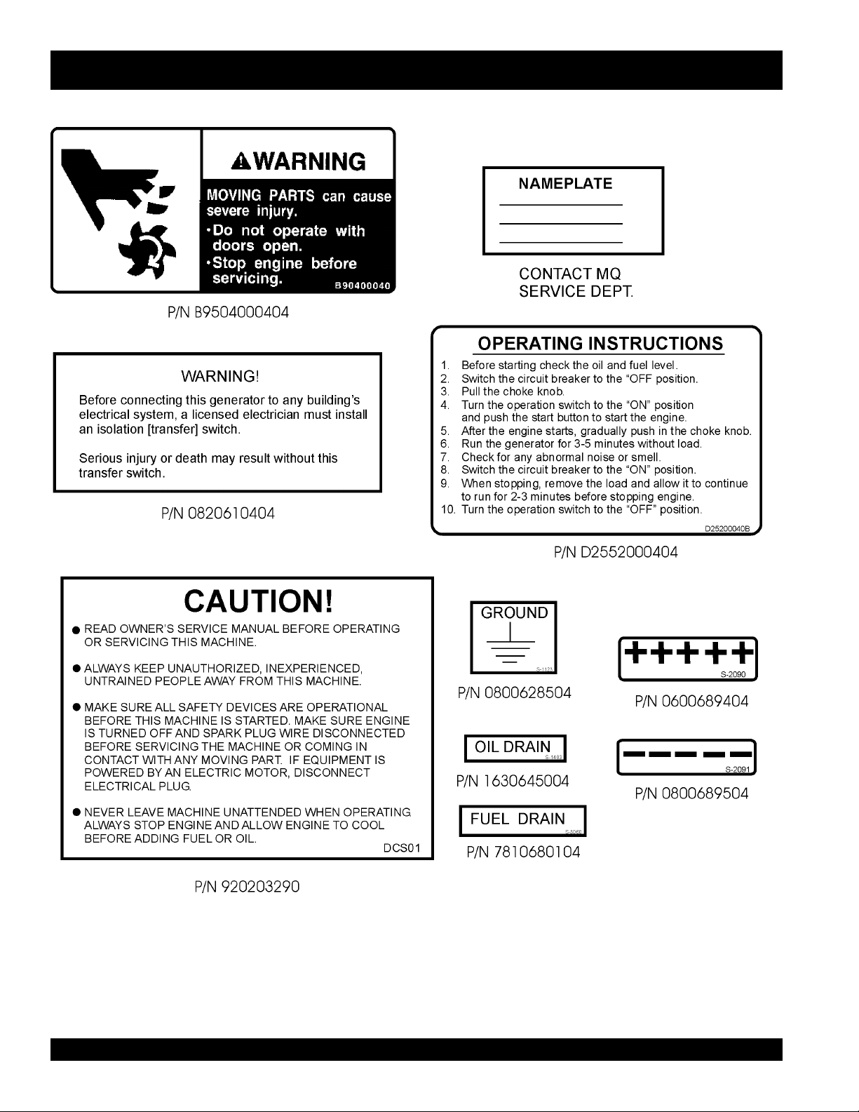
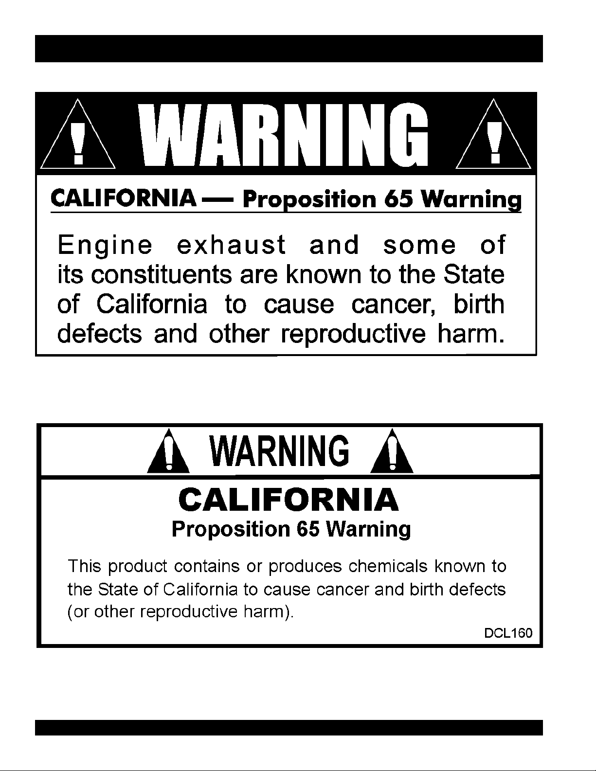
OPERATION AND SAFETY DECALS
PAGE 8 — SGW-250SS DC WELDER/AC GENERATOR— PARTS & OPERATION MANUAL — REV. #2 (08/08/01)
Page 9
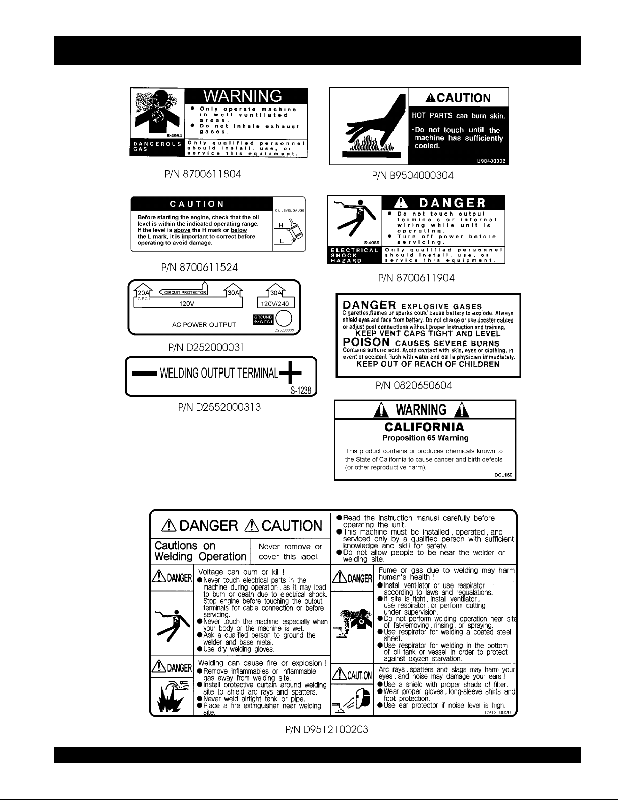
OPERATION AND SAFETY DECALS
P/N DCL160
SGW-250SS DC WELDER/AC GENERATOR — PARTS & OPERATION MANUAL — REV. #2 (08/08/01) — PAGE 9
Page 10

)CC/VC(tuptuOdetaRWk6.5/0.4
)CC(tnerruCdetaRspmA002
)CC/VC(egatloVdetaRstloV82/02
elcyCytuD%001
deepSdetaRmpr/0063
egnaRegatloVstloV82-51
egnaRtnerruCspmA522-05
esahPesahPelgniS
seriW)dednuorGlartueN(seriW-3
tuptuOdetaRWk2.7
egatloVdetaRstloV042/021
ycneuqerFzH06
rotcaFrewoP0.1
gnitaRsuounitnoC
ledoMDXV016XGADNOH
epyTVHO,EKORTS-4
tuptuOdetaR
tnemecalpsiD)cc416(ni.uc5.73
metsySgnilooCriadecroF
metsySgnitratStratScirtcelE
yticapaCknaTleuFsretil83/lag01
yticapaCliOebuLsretil5.1/lag04.0
:noitpmusnoCleuF
gnidleWVC.rh/)sretil15.3(lag39.0
gnidleWCC.rh/)sretil22.4(lag11.1
rewoPCA.rh/)sretil83.4(lag61.1
yrettaBhA53-V21
leuFenilosaGdedaelnU
)HxWxL(snoisnemiD
thgieWyrD)gk152(.sbl355
SGW-250SS — SPECIFICATIONS
snoitacificepS.1elbaT
snoitacificepSredleW
snoitacificepSrotareneG
snoitacificepSenignE
PH4.41/Wk7.01
mpr0063@
mm518x095x0701
)ni1.23x2.32x1.24(
The maximum output of the engine listed above is applicable to supplying electrical power for continuous service at ambient
conditions in accordance with SAE Test cord J607. The above ambient conditions are at standard sea level, with a barometric
reading of 29.92 inches and a temperature of 60 degrees fahrenheit.
°°
°
°°
Generally, the engine output power will decrease 3 1/2% for each 1000 feet of altitude above sea level, and 1% for each 10
°°
°
fahrenheit above the standard temperature of 60
°°
F
F
PAGE 10 — SGW-250SS DC WELDER/AC GENERATOR— PARTS & OPERATION MANUAL — REV. #2 (08/08/01)
Page 11

SGW-250SS — GENERAL INFORMATION
SGW-250SS FAMILIARIZATION
Generator
The MQ Power Model SGW-250SS welder/generator can
provide 200 amps of welding current when in the CV/DC
mode and 250 amps of welding current when in the CC/DC
mode. When used as a generator it can provide a maximum
of 7,200 watts of power.
Control Panel
control panelcontrol panel
The
control panel
control panelcontrol panel
z
One GFCI 120 volt receptacle, 30 amp (single-phase)
z
One 120 volt receptacle, 30 amp (single-phase)
z
One 120/240 volt receptacle, 30 amp (single-phase)
z
Main Circuit Breaker 265V @25 Amps
z
Circuit Protector Breaker (GFCI) 120V @20 Amps
z
Idle Control Switch
z
Starter Switch
z
Starter Button
z
Hour Meter
z
Ground Terminal
Welder Protection System
In the event of an overload, this welder/generator is equipped
with an welder protection system . If an overload is detected
while operating the welder/generator, the welder protection
system will shut down the engine.
is provided with the following:
Oil Pressure Warning Alarm
In the event of low oil pressure (engine), this welder/generator
is equipped with an engine protection fail safe system . If
low oil pressure is detected while operating the welder/
generator, the engine protection system will shut down the
engine.
If this condition (low oil pressure) should occur, please refer
to the engine troubleshooting table in this manual.
Excitation System
The SGW-250SS welder/generator uses a brushless
exciter to create rated output electricity. This system will
use the mechanical energy generated by the 3600 RPM
engine to spin the rotor (or armature) inside the generator
(or alternator end).
The motion created by the rotor (which holds copper coils)
spins inside a housing of permanent magnets called the
"STATOR". A magnetic field is created by the stator and
produces an electrical current.
Engine
The SGW-250SS is powered by an air-cooled, 4-cycle
HONDA gasoline engine. This engine is designed to meet
every performance requirement for generator. Reference
Table 1, page 9 for engine specifications.
In keeping with MQ Power's policy of constantly improving
its products, the specifications quoted herein are subject to
change without prior notice.
Figures 2 and 3 (pages 14-15) show the basic controls and
indicators for the SGW-250SS welder/generator.
SGW-250SS DC WELDER/AC GENERATOR — PARTS & OPERATION MANUAL — REV. #2 (08/08/01) — PAGE 11
Page 12
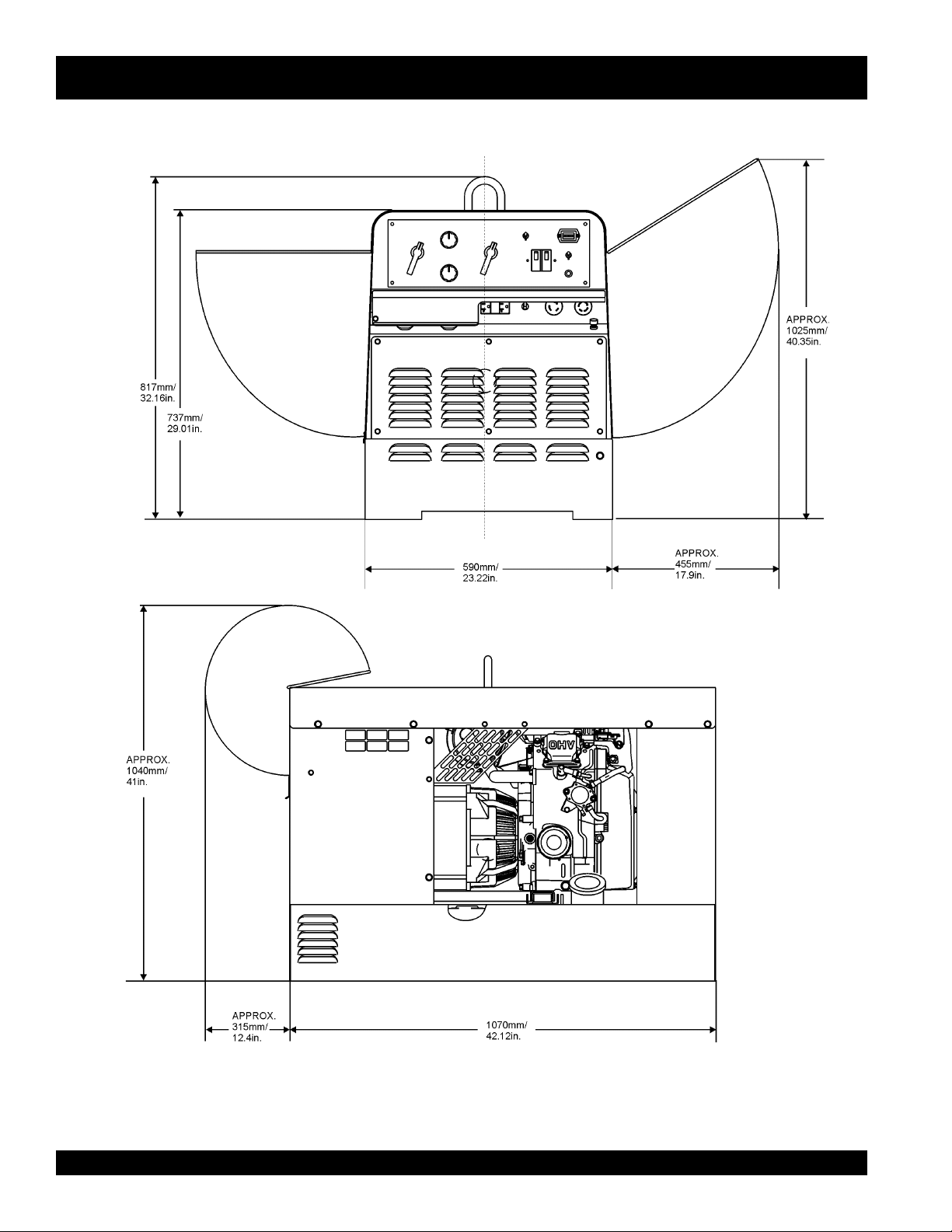
SGW-250SS — DIMENSIONS
Figure 1. SGW-250SS Dimensions
PAGE 12 — SGW-250SS DC WELDER/AC GENERATOR— PARTS & OPERATION MANUAL — REV. #2 (08/08/01)
Page 13

SGW-250SS — TRAILER-SAFETY GUIDELINES
CAUTION:
ALWAYS make sure the trailer is in good
operating condition. Check the tires for
proper inflation and wear. Also check the
wheel lug nuts for proper tightness.
Explanation of Chart:
This section is intended to provide the user with trailer service and maintenance information. The service and maintenance guidelines referenced in this section apply a wide
range of trailers. Remember periodic inspection of the trailer
will ensure safe towing of the equipment and will prevent
damage to the equipment and personal injury.
It is the purpose of this section to cover the major maintenance components of the trailer. The following trailer components will be discussed in this section:
Brakes
Tires
Lug Nut Torquing
Suspension
Electrical
Brake Troubleshooting Tables
Use the following definitions with reading Table 2.
1. Fuel Cell - Provides an adequate amount of fuel for
the equipment in use. Fuel cells must be empty when
transporting equipment.
2. Braking System - System employed in stopping the
trailer. Typical braking systems are electric, surge, hydraulic, hydraulic-surge and air.
3. GVWR- Gross Vehicle Weight Rating (GVWR), is the
maximum number of pounds the trailer can carry, including the fuel cell (empty).
4. Frame Length - This measurement is from the ball
hitch to the rear bumper (reflector).
5. Frame Width - This measurement is from fender to
fender.
6. Jack Stand - Trailer support device with maximum
pound requirement from the tongue of the trailer.
7. Coupler - Type of hitch used on the trailer for towing.
8. Tire Size - Indicates the diameter of the tire in inches
(10,12,14, etc.), and the width in millimeters
(175,185,205, etc.). The tire diameter must match the
diameter of the tire rim.
9. Tire Ply - The tire ply (layers) number is rated in letters;
2-ply,4-ply,6-ply, etc.
10. Wheel Hub - The wheel hub is connected to the trailer’s
axle.
11. Tire Rim - Tires mounted on a tire rim. The tire rim must
match the size of the tire.
12. Lug Nuts - Used to secure the wheel to the wheel hub.
Always use a torque wrench to tighten down the lug
nuts. See Table 4 and Figure 5 or lug nut tightening and
sequence.
13. Axle - Indicates the maximum weight the axle can support in pounds, and the diameter of the axle expressed
in inches (see Table 3). Please not that some trailers
have a double axle. This will be shown as 2-6000 lbs.,
meaning two axles with a total weight capacity of 6000
pounds.
14. Suspension - Protects the trailer chassis from shocks
transmitted through the wheels. Types of suspension
used are leaf, Q-flex, and air ride.
15. Electrical - Electrical connectors (looms) are provided
with the trailer so the brake lights and turn signals can
be connected to the towing vehicle.
16. Application - Indicates which units can be employed
on a particular trailer.
SGW-250SS DC WELDER/AC GENERATOR — PARTS & OPERATION MANUAL — REV. #2 (08/08/01) — PAGE 13
Page 14

SGW-250SS — TRAILER-SPECIFICATIONS
snoitacificepS.1elbaT
LEDOM NOITACILPPA LEUF
LLEC
W01-RLRT ,522WDS
003WLT,052WGS
01-RLRT ,21GLT,01ACD
51-ACD
FX01-RLRT ,21-GLT,01ACD
003-WLT,51ACD
W522-RLRT ,SREDLEW
SS0007AD
004WLB-RLRT 004-WLBONCIRTCELESBL0072"451TSAM/W
X05-RLRT 52-ACDONONSBL0072"421"55.BL008
FX05-RLRT 52-ACDLAG14ONSBL0072"421"55.BL008
W07-RLRT 07,06-,54-ACDONEGRUSSBL0007"681"77.BL0002
X07-RLRT 07,06-,54-ACDTPOEGRUSSBL0007"831"66.BL0002
FX07-RLRT 07,06-,54-ACDLAG35EGRUSSBL0007"831"66.BL0002
FX001-RLRT 521,001-ACDLAG051EGRUSCILUARDYHSBL0007"091"67.BL0002
521/58-RLRT ,001,58-ACD
521
FX051-RLRT 081,051-ACDLAG002EGRUSCILUARDYHSBL06111"402"48.BL0005
FX022-RLRT 022-ACDLAG052EGRUSCILUARDYHSBL00041"222"38.BL0005
FX003-RLRT 003-ACDLAG052EGRUSCILUARDYHSBL00081"832"38.BL0005
FX004-RLRT 004-ACDLAG053CIRTCELESBL00081"832"38.BL0005
FX006-RLRT 008,006-ACDLAG055RIASBL00003"483"69.BL0005
XS008-RLRT 008,006-ACDLAG055RIASBL00003"483"69.BL0005
ONONSBL0091"69"05.BL008
ONONSBL0091"69"05.BL008
LAG25ONSBL0091"69"05.BL008
ONONSBL0022"58"24.BL008
LAG541CILUARDYHSBL00001"681"77.BL0002
EKARB
METSYS
RWVG EMARF
EMARF
HTGNEL
"421O/W
HTDIW
"55
)LLAT"87(
KCAJ
DNATS
LEEHWTLITLLUF
LEEHWTLITLLUF
LEEHWTLITLLUF
LEEHWTLITLLUF
.BL008
LEEHWTLITLLUF
LEEHWTLITLLUF
LEEHWTLITLLUF
DAPTALF
DAPTALF
DAPTALF
DAPTALF
DAPTALF
DAPTALF
DAPTALF
DAPTALF
DAPTALF
DAPTALF
DAPTALF
PAGE 14 — SGW-250SS DC WELDER/AC GENERATOR— PARTS & OPERATION MANUAL — REV. #2 (08/08/01)
Page 15

SGW-250SS — TRAILER-SPECIFICATIONS
)t'noC(snoitacificepS.1elbaT
LEDOM RELPUOC SERIT SLEEHW ELXA SBUH NOISNEPSUS LACIRTCELE
W01-RLRT SSALCLLAB"2
01-RLRT SSALCLLAB"2
FX01-RLRT SSALCLLAB"2
W522-RLRT SSALCLLAB"2
WLB-RLRT
004
X05-RLRT SSALCLLAB"2CRL31-87B"05.4X"31.sbl0053
FX05-RLRT SSALCLLAB"2CRL31-87B"05.4X"31.sbl0053
W07-RLRT SSALCLLAB"2
X07-RLRT SSALCLLAB"2
FX07-RLRT SSALCLLAB"2
FX001-RLRT 6/5-2ELBATSUJDA
521/58-RLRT 6/5-2ELBATSUJDA
FX051-RLRT EYELLAB"3E61-057
FX022-RLRT EYE"3
FX003-RLRT EYE"3
FX004-RLRT EYE"3
FX006-RLRT LEEHWHT5H5.71R57/512TS
RA008-RLRT LEEHWHT5H5.71R57/512TS
ELBATSUJDA2
ELBATSUJDA2
ELBATSUJDA2
ELBATSUJDA2
SSALCLLAB"2
ELBATSUJDA2
ELBATSUJDA"3
ELBATSUJDA"3
ELBATSUJDA"3
EYE"3TPO
EYE"3TPO
ELBATSUJDA
ELBATSUJDA
ELBATSUJDA
C31-571"05.4X"312X2#0022GUL5FAEL3/WMOOLERIW4
C31-571"5.4X"312X2#0022GUL5FAEL3TALFELOP4
C31-571"5.4X"312X2#0022GUL5FAEL3TALFELOP4
B31-571"5.4X312X2#0022GUL5XELFQTALFELOP4
C31-571"5.4X312X2#0022GUL5FAEL3TALFELOP4
"8/3-2
"8/3-2
C41-502
)4(SAIB
C41-502
)4(SAIB
C41-502
)4(SAIB
C51-502
)4(SAIB
D51R57/522TS
)4(LAIDAR
)4(SAIB
E61R58/532TS
)4(LAIDAR
E61R58/532TS
)6(LAIDAR
E61R58/532TS
)6(LAIDAR
)8(LAIDAR
)8(LAIDAR
"5X"41.sbl0053
"3
"5X"41sbl0053
"3
"5X"41.sbl0053
"3
"5.5X"41sbl0053
"3
"6x"41sbl0006-)2(GUL6FAEL7MOOLERIW4
"7X"61sbl0006-)2(GUL8FAEL7MOOLERIW4
"7X"61sbl0007-)2(GUL8XELFQMOOLERIW4
"7X"61sbl0006-)2(GUL8XELFQMOOLERIW4
"7X"61.sbl0007-)3(GUL8XELFQMOOLERIW4
"7X"61sbl00001-)3(GUL8FAEL7MOOLERIW6
"7X"61sbl00001-)3(GUL8EDIR-RIAMOOLERIW6
GUL5FAEL4REBBURELOP4
GUL5FAEL4REBBURELOP4
GUL5FAEL5REBBURELOP4
GUL5FAEL5REBBURELOP4
GUL5FAEL5REBBURELOP4
GUL5FAEL5MOOLERIW4
TALFELOP4
TALF
TALF
TALF
TALF
TALF
SGW-250SS DC WELDER/AC GENERATOR — PARTS & OPERATION MANUAL — REV. #2 (08/08/01) — PAGE 15
Page 16
SGW-250SS —TRAILER SAFETY GUIDELINES
Tires/Wheels/Lug Nuts
Tires and wheels are a very important and critical
components of the trailer. When specifying or replacing the
trailer wheels it is important the wheels, tires, and axle are
properly matched.
CAUTION:
DO NOT attempt to repair or modify a
wheel. DO NOT install in inner tube to
correct a leak through the rim. If the rim
is cracked,
the air
pressure in
the inner tube may cause pieces
of the rim to explode (break off)
with great force and cause serious
eye or bodily injury.
Tire Wear/Inflation
Tire inflation pressure is the most important factor in tire life.
Pressure should be checked cold before operation DO NOT
bleed air from tires when they are hot. Check inflation
pressure weekly during use to insure the maximum tire life
and tread wear.
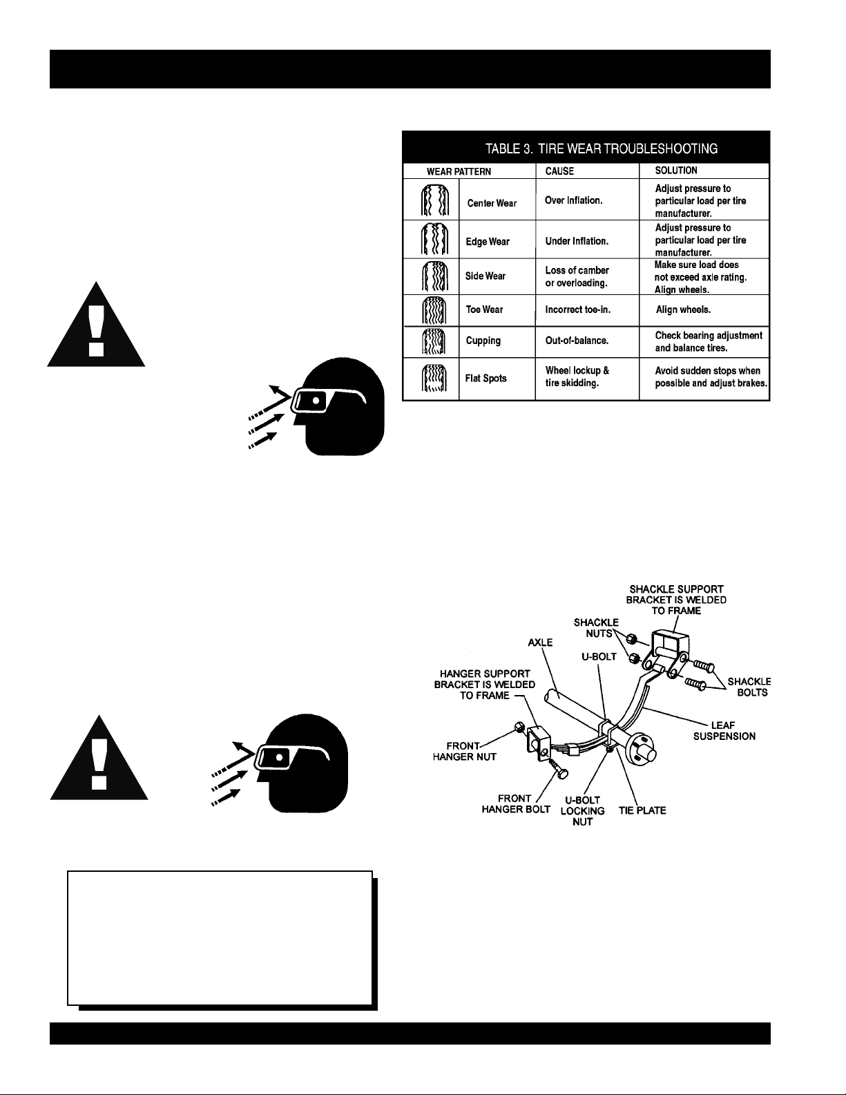
Table 3 (Tire Wear Troubleshooting) will help pinpoint the
causes and solutions of tire wear problems.
Suspension
The leaf suspension springs and associated components
(Figure 2) should be visually inspected every 6,000 miles for
signs of excessive wear, elongation of bolt holes, and
loosening of fasteners. Replace all damaged parts
(suspension) immediately. Torqued suspension components
as detailed in Table 4.
CAUTION:
Figure 2. Major Suspension Components
NOTE
ALWAYS wear safety glasses when removing
or installing force fitted parts. Failure to
comply may result in serious injury.
PAGE 16 — SGW-250SS DC WELDER/AC GENERATOR— PARTS & OPERATION MANUAL — REV. #2 (08/08/01)
Page 17
metI ).sbL-.tF(euqroT
TLOB-U"8/353-XAM03-NIM
TLOB-U"61/706-XAM54-NIM
TLOB-U"2/106-XAM54-NIM
SGW-250SS —TRAILER SAFETY GUIDELINES
stnemeriuqeReuqroTnoisnepsuS.4elbaT
SHACKLE BOLT
SPRING EYE BOLT
SHOULDER TYPE
SHACKLE BOLT
SNUG FIT ONLY.PARTS MUST ROTATE FREELY
LOCKING NUTS OR COTTER PINS ARE PROVIDED TO
-
RETAIN NUT
BOLT ASSEMBLY
.
05-XAM03-NIM
.
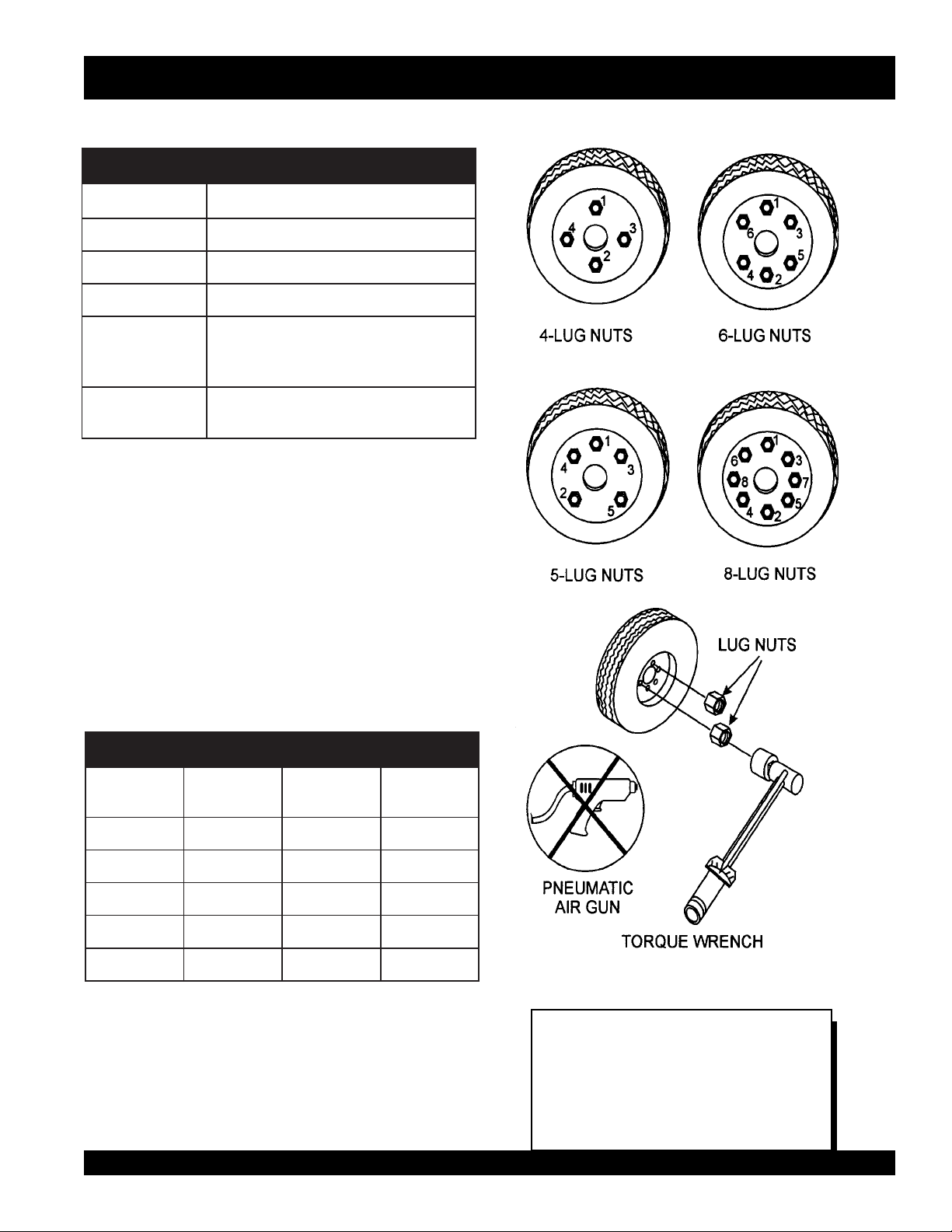
Lug Nut Torque Requirements
It is extremely important to apply and maintain proper wheel
mounting torque on the trailer. Be sure to use only the
fasteners matched to the cone angle of the wheel. Proper
procedure for attachment of the wheels is as follows:
1. Start all wheel lug nuts by hand.
2. Torque all lug nuts in sequence. See Figure 3. DO NOT
torque the wheel lug nuts all the way down. Tighten
each lug nut in 3 separate passes as defined by Table 5.
3. After first road use, retorque all lug nuts in sequence.
Check all wheel lug nuts periodically.
stnemeriuqeReuqroTeriT.5elbaT
eziSleehWssaPtsriF
SBL-TF
"2152-0204-5356-05
"3152-0204-5356-05
"4152-0206-05021-09
"5152-0206-05021-09
"6152-0206-05021-09
ssaPdnoceS
SBL-TF
ssaPdrihT
SBL-TF
Figure 3. Wheel Lug Nuts Tightening Sequence
NOTE
NEVER use an pneumatic air gun to
tighten wheel lug nuts.
SGW-250SS DC WELDER/AC GENERATOR — PARTS & OPERATION MANUAL — REV. #2 (08/08/01) — PAGE 17
Page 18
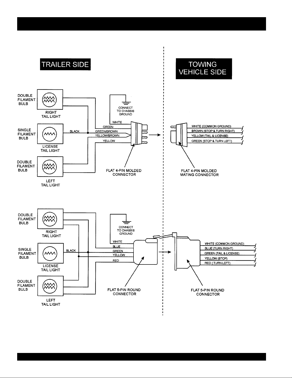
SGW-250SS —TRAILER-WIRING DIAGRAM
PAGE 18 — SGW-250SS DC WELDER/AC GENERATOR— PARTS & OPERATION MANUAL — REV. #2 (08/08/01)
Page 19
SGW-250SS —TOWING
Towing Safety Precautions
■
ALWAYS attach trailer's safety chain to bumper of towing
vehicle.
CAUTION :
■
ALWAYS make sure the vehicle and trailer directional,
Check with your county or state safety
towing regulations department before
towing your generator. Vehicle towing
codes and regulations can vary from state
to state.
To reduce the possibility of an accident while transporting
the generator on public roads, always make sure the trailer
(Figure 4) and the towing vehicle are in good operating
condition and both units are mechanically sound.
The following list of suggestions should be used when towing
your generator:
■
Make sure the hitch and coupling of the towing vehicle are
rated equal to, or greater than the trailer "gross vehicle weight
rating" (GVWR).
■
ALWAYS inspect the hitch and coupling for wear. NEVER
tow a trailer with defective hitches, couplings, chains etc.
■
Check the tire air pressure on both the towing vehicle and
the trailer. Also check the tire tread wear on both vehicles.
■
ALWAYS make sure the trailer is equipped with a "Safety
Chain".
backup, brake, and trailer lights are connected and are
working properly.
■
The maximum speed (unless otherwise posted) for highway
towing is 45 MPH. Recommended off-road towing is not to
exceed 10 MPH or less, depending on type of terrain.
■
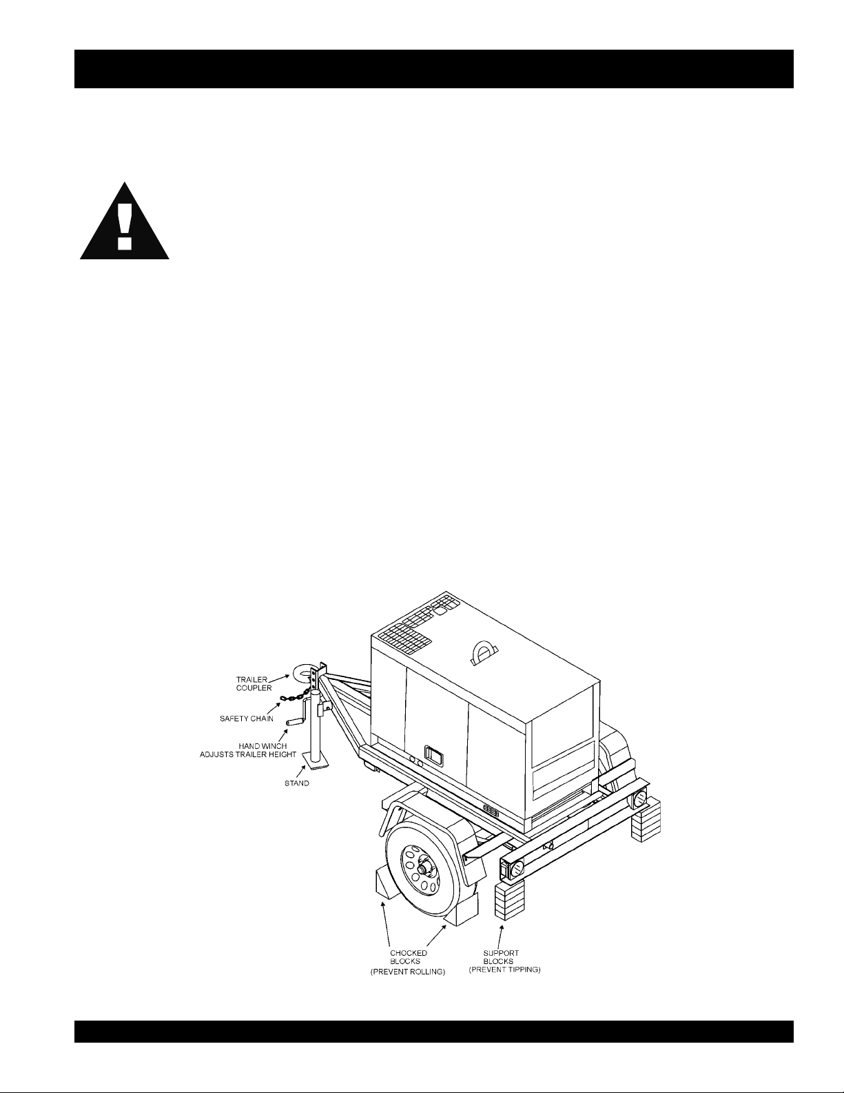
Place
while parked.
■
Place
prevent
■
Use the trailer's hand winch to adjust the height of the trailer,
then insert locking pin to lock wheel stand in place, while
parked.
■
Avoid sudden stops and starts. This can cause skidding, or
jackknifing. Smooth, gradual starts and stops will improve
gas milage.
■
Avoid sharp turns to prevent rolling.
■
Remove wheel stand when transporting.
■
DO NOT transport generator with fuel in tank.
chocked blocks
support blocks
tippingtipping
tipping
tippingtipping
underneath wheel to prevent
underneath the trailer's bumper to
, while parked.
rolling rolling
rolling,
rolling rolling
Figure 4. Welder/AC Generator and Towing Trailer
SGW-250SS DC WELDER/AC GENERATOR — PARTS & OPERATION MANUAL — REV. #2 (08/08/01) — PAGE 19
Page 20
POWERED
by
SGW-250SS — CONTROLS AND INDICATORS
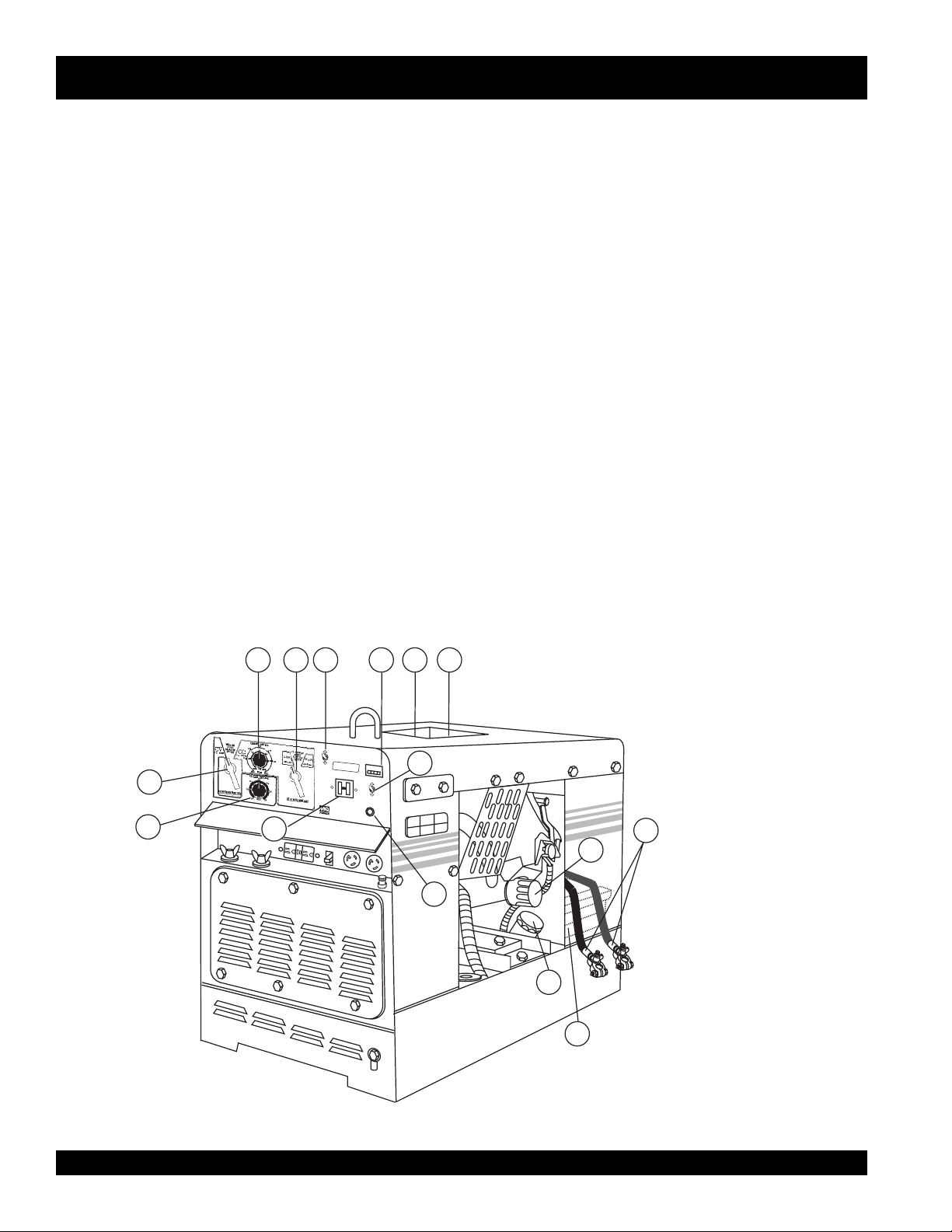
Figures 5 and 6 show the location of the controls and indicators.
The functions of each control or indicator is described below
and on the preceding page.
1. Welding Type (Wire/Stick) Selector Switch (CV/CC) –
Turn this selector switch to either the CV or CC for
welding. DO NOT turn this switch under load.
2. Current Range Selector Switch (CV/CC) – Turn this
selector switch to either the CV or CC for welding. DO
NOT turn this switch under load.
3. Current Control (CC) Adjustment Knob – Use this
control to adjust welding current. Low scale (50~120 amps),
High scale (90~250 amps). This function will not work in
the CV mode.
4. Voltage Control (CV) Adjustment Knob – Use this
control to adjust the welding voltage. This function will not
work in the CC mode.
5. Idle Control Switch – Regulates the engine speed when
the generator is under load.
6. Hour Meter – Indicates number of hours the welder has
been in use or engine has been running.
7. Oil Filler Port – Use this port when adding oil to the
engine.
8. Engine Air Cleaner – Prevents dirt and other debris
from entering the fuel system. Lift locking latch on air
filter cannister to gain access to filter element.
9. Main Circuit Breaker – This 2-pole circuit breaker provides
circuit protection (265V @30 amps) for the electric parts.
10. ON/OFF Switch – This switch is used to start and stop the
engine. Must be in th ON position (up) when starting the
engine. Place in the OFF position (down) to stop the engine.
11. Start Button – Press and hold this push-button switch
until the engine has started. The ON/OFF switch must be
in the ‘ON’ position in order for the start push-button switch
to start the engine.
12. Oil Filter – Provides oil filtering for the engine.
13. Fuel Cap – Remove this cap to add fuel. Add only clean
unleaded fuel. Always keep an adequate amount of fuel
in the tank. DO NOT top off. Wipe up any spilled fuel
immediately.
14. Battery Terminals – Connect these terminals to the
battery. Always pay close attention to the polarity of the
terminals when connecting to the battery, RED (positive),
and BLACK (negative).
15. Battery – Provides +12 VDC power for the generator.
When replacing battery (12V 35 AH) use only
3 2
5
6
7 8
recommended type battery.
O
N
WHISPERWELD
S
G
W
-250S
S
O
F
F
POWERED
by
O
N
T
R
O
L
MQ POWER
Q
U
A
R
H
T
Z
O
N
D
A
AC
C
I
R
C
U
I
T
B
R
E
A
K
E
R
H
O
U
R
M
E
T
ON
OFF
O
P
E
R
A
T
I
O
N
S
W
I
T
C
H
S
T
A
R
T
B
U
T
T
O
N
10
E
R
Power Source Professionals.
11
I
D
L
E
C
1
4
9
MQ POWER
MQ POWER
14
12
13
15
Figure 5. SGW250SS Components 1
PAGE 20 — SGW-250SS DC WELDER/AC GENERATOR— PARTS & OPERATION MANUAL — REV. #2 (08/08/01)
Page 21

POWERED
by
WHISPER WELD
MQ POWER
HC
PowerSource Professionals.
30
28
29
SGW-250SS — CONTROLS AND INDICATORS
16. Positive Welding Output Terminal – Connect the
23. Frame Ground Lug – Connect a ground strap between
welding cable to this terminal. Select the appropriate
polarities according to the application. See Table 7.
17. Negative Welding Output Terminal – Connect the
negative cable of the welding source to this terminal.
Select the appropriate polarities according to the
24. Fuel Tank – Holds 10 gallons (38 liters) of unleaded
application. See Table 7.
18. Receptacle G.F.C.I. – This receptacle provides 120 volts
25. Fuel Gauge – Indicates the amount of fuel in the fuel
and output @ 20 amps.
19. Circuit Protector Circuit Breaker – This single pole circuit
26. Choke Knob – Used in the starting of a cold engine, or
breaker provides circuit protection (250V @20 amps) for
the G.F.C.I receptacle.
20. Receptacle – Provides 120 volts output @ 25 amps.
21. Receptacle – Provides 120/240 volts output @ 25 amps.
27. Lifting Hook – Use this hook to lift the generator.
28. Engine Oil Dipstick – Indicates engine oil level, add oil
22. G.F.C.I Ground Terminal – Use this terminal to connect
external equipment grounds so the G.F.C.I. receptacle will
29. Oil Drain Plug – Remove this plug to drain oil from the
have a ground path.
30. Fuel drain Plug – Remove this plug to drain fuel from
O
N
WHISPERWELD
S
G
W
-2
5
O
F
F
POWEREDby
IDLECONTROL
H
O
N
D
A
AC CIRCUIT
BREAKER
MQ POWER
27
0S
S
Q
U
A
R
T
Z
H
O
U
R
M
E
T
E
R
O
N
O
F
F
O
P
E
R
A
T
IO
N
S
W
IT
C
H
S
T
A
R
T
B
U
T
T
O
N
MQ POWER
26
this lug and a ground rod. Make sure the ground rod is
inserted deep into the ground to provide a good earth
ground. Consult with local Electrical and Safety Codes
for proper connection.
fuel.
tank.
in cold weather conditions. The choke enriches the fuel
mixture for starting a cold engine.
as required. See Table 3 for correct type of oil.
engine.
the fuel tank.
16
17
Power Source Professionals.
MQ POWER
18
19
20
21
22
23
24
25
FRONT VIEW
Figure 6. SGW250SS Components 2
SGW-250SS DC WELDER/AC GENERATOR — PARTS & OPERATION MANUAL — REV. #2 (08/08/01) — PAGE 21
Page 22
SGW-250SS — INSTALLATION
Outdoor Installation
Install the welder/generator in a location where it will not be
exposed to rain or sunshine. Make sure the welder/generator
is on secure level ground so that it cannot slide or shift
around. Install the generator in a manner so the exhaust
fumes will not be discharged in the direction of nearby homes.
The installation site must be relatively free from moisture
and dust. All electrical equipment should be protected from
excessive moisture. Failure to do will result in deterioration
of the insulation and will result in short circuits and grounding.
Foreign materials such as dust, sand, lint and abrasive
materials will cause excessive wear, to the engine and
alternator parts.
Indoor Installation
Exhaust gases from gasoline engines are extremely
poisonous. Whenever an engine is installed indoors the
exhaust fumes must be vented to the outside. The engine
should be installed at least two feet from any outside wall.
Using an exhaust pipe which is too long or too small can
cause excessive back pressure which will cause the engine
to heat excessively and possibly burn the valves.
Eliminate the danger of deadly carbon monoxide gas.
Remember that exhaust fumes from any gasoline engine
are very poisonous if discharged in a closed room, but
harmless if allowed to mix with the outside air. If the generator
is installed indoors, you must make provisions for venting
the engine exhaust to the outside of the building.
CAUTION
CAUTION :
Pay close attention to ventilation when
operating the generator inside tunnels and
caves. The engine exhaust contains
noxious elements.
:
An electric shock may happen when
vibrators are used. Pay close attention to
handling when operating vibrators and
always use rubber boots and gloves to
insulate the body from electrical shock.
Selecting Optimum Welding Cable
Use the table below (Table 2) to select the best cable for the
total length and current of the application being used.
/)tf(htgneLelbaClatoT
)A(tnerruC
0014#4#4#3#3#2#1#
0513#3#3#2#1#0/1#0/2#
0022#2#2#1#0/1#0/2#0/3#
0521#1#1#0/1#0/2#0/3#0/4#
05001521051002052003
Note:
During the operation of Self-Sheld Welding ro MIG
Welding, do not allow the cables to bundle, because it
will cause a short current drop. This may also happen
if the size of the cables are smaller than recommended.
seziSelbaCgnidleW.6elbaT
PAGE 22 — SGW-250SS DC WELDER/AC GENERATOR— PARTS & OPERATION MANUAL — REV. #2 (08/08/01)
Page 23

SGW-250SS — PRE-SETUP
General Inspection Prior to Operation
The SGW-250SS utilizes a generator that has been thoroughly
inspected and accepted prior to shipment from the factory.
However, be sure to check for damaged parts or components,
or loose nuts and bolts, which could have occurred in transit.
Ground
The nut and ground terminal on the generator should always
be used to connect the generator to a suitable ground. The
ground path should be of #8 size wire.
Connect the terminal of the ground wire between the lock
washer and the nut and tighten the nut fully. Connect their
end of the wire to a suitable ground.
Circuit Breaker
To protect the generator from an overload, a 2-pole, 30 amp,
circuit breaker is provided. Make sure to switch the circuit
breaker to the "OFF" position prior to starting the engine.
Extension Cable
When electric power is to be provided to various tools or
loads at some distance from the generator, extension cords
are normally used. Cables should be sized to allow for
distance in length and amperage so that the voltage drop
between the generator and point of use (load) is held to a
minimum. Use the cable selection chart (Table 3 ) as a guide
for selecting proper cable size.
elbaCrotareneG.7elbaT
sttaWnIdaoLhtgneLelbaCelbawollAmumixaM
nitnerruC
serepmA
5.2003006.tf0001.tf006.tf573.tf052
50060021.tf005.tf003.tf002.tf521
5.70090081.tf053.tf002.tf521.tf001
0100210042.tf052.tf051.tf001
5100810063.tf051.tf001.tf56
0200420084.tf521.tf57.tf05
021tA
stloV
042tA
stloV
eriW01#eriW21#eriW41#eriW61#
.egatlovwolmorftlusernacegamadtnempiuqE:NOITUAC
SGW-250SS DC WELDER/AC GENERATOR — PARTS & OPERATION MANUAL — REV. #2 (08/08/01) — PAGE 23
Page 24
SGW-250SS — PRE-SETUP
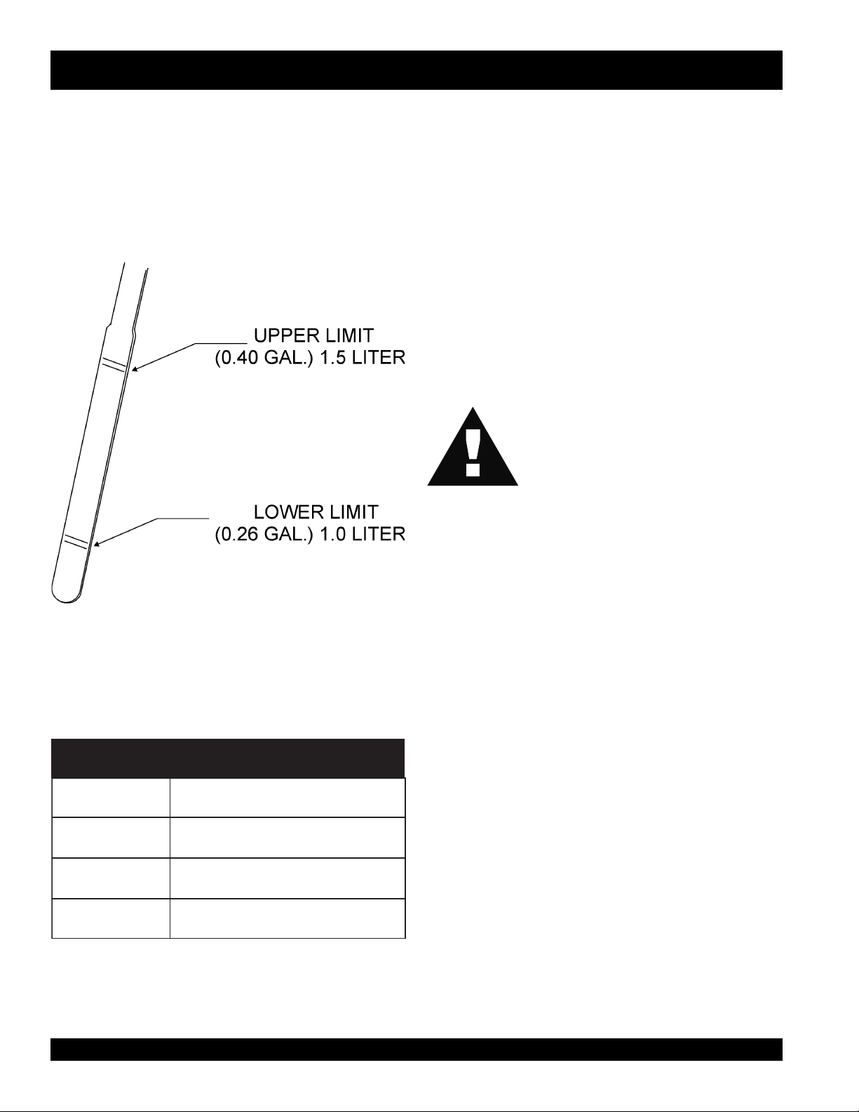
Lubrication Oil
Fill the engine crankcase with lubricating oil through the filler
hole, but do not overfill. Make sure the welder/generator is
level. With the dipstick inserted all the way, but without being
screw into the filler hole, verify that the oil level is maintained
between the two notches (Figure 7) on the dipstick. See
Fuel
Fill the fuel tank with clean and fresh unleaded gasoline. DO
NOT fill the tank beyond capacity.
Pay attention to the fuel tank capacity when replenishing
fuel. Refer to the fuel tank capacity listed on page 11,
Specification Table 1.
Table 4 for proper selection of engine oil.
The fuel tank cap must be closed tightly after filling. Handle
fuel in a safety container. If the container does not have a
spout, use a funnel.
CAUTION :
Never fill the fuel tank while the engine is
running or in the dark. Gasoline spillage
on a hot engine can cause a fire or
explosion. If gasoline spillage occurs, wipe
up the spilled gasoline completely to
prevent fire hazards.
Figure 7. Engine Oil Dipstick
egnaRerutarepmeTliOepyT
F°32~F°401
)C°5-~C°04(
F°5~F°32
)C°51-~C°5-(
)°51-(C°5woleB03-W01EASroW01EAS
03EAS
Air Cleaner
Periodic cleaning/replacement is necessary. Inspect it in
accordance with the engine manual.
Battery
This unit is of negative ground. DO NOT connect in reverse.
Always maintain battery fluid level between the specified
marks. Battery life will be shortened, if the fluid level is not
properly maintained. Add only distilled water when
replenishment is necessary.
The battery is sufficiently charged if the specific gravity of
liOrotoMdednemmoceR.8elbaT
the battery fluid is 1.28 (at 68° F). If the specific gravity
should fall to 1.245 or lower, it indicates that the battery is
dead and needs to be recharged or replaced.
Check to see whether the battery cables are loose. Poor
contact may result in poor starting or malfunctions, always
keep the terminals firmly tightened. Coating the terminals
03-W01EASro02EAS
with a thin film of grease will help to inhibit corrosion.
The battery gradually deteriorates over time. The actual life
span will vary according to operating conditions, but
generally a battery two years or older should be replaced.
PAGE 24 — SGW-250SS DC WELDER/AC GENERATOR— PARTS & OPERATION MANUAL — REV. #2 (08/08/01)
Page 25
BLW-400SSW — PRE-SETUP
CAUTION
Day-to-day addition of coolant or antifreeze is done from the
reserve tank. See Table 9 for engine, radiator and reserve
tank coolant capacities. Make sure the coolant level in the
reserve tank is always between the "H" and the "L" markings.
Operation in Freezing Weather
When operating in freezing weather, be certain that the proper
amount of antifreeze has been added. See Table 10 for
antifreeze operating temperatures.
:
When adding coolant or antifreeze to the
radiator, do not remove the radiator cap
until the unit has completely cooled.
yticapaCtnalooC.9elbaT
rotaidaRdnaenignE)L61.4(.laG1.1
knaTevreseR)L57.0(.laG2.0
Cleaning the Radiator
The radiator may overheat if the fins become overloaded
with dust or debris. Periodically clean the radiator fins with
compressed air.
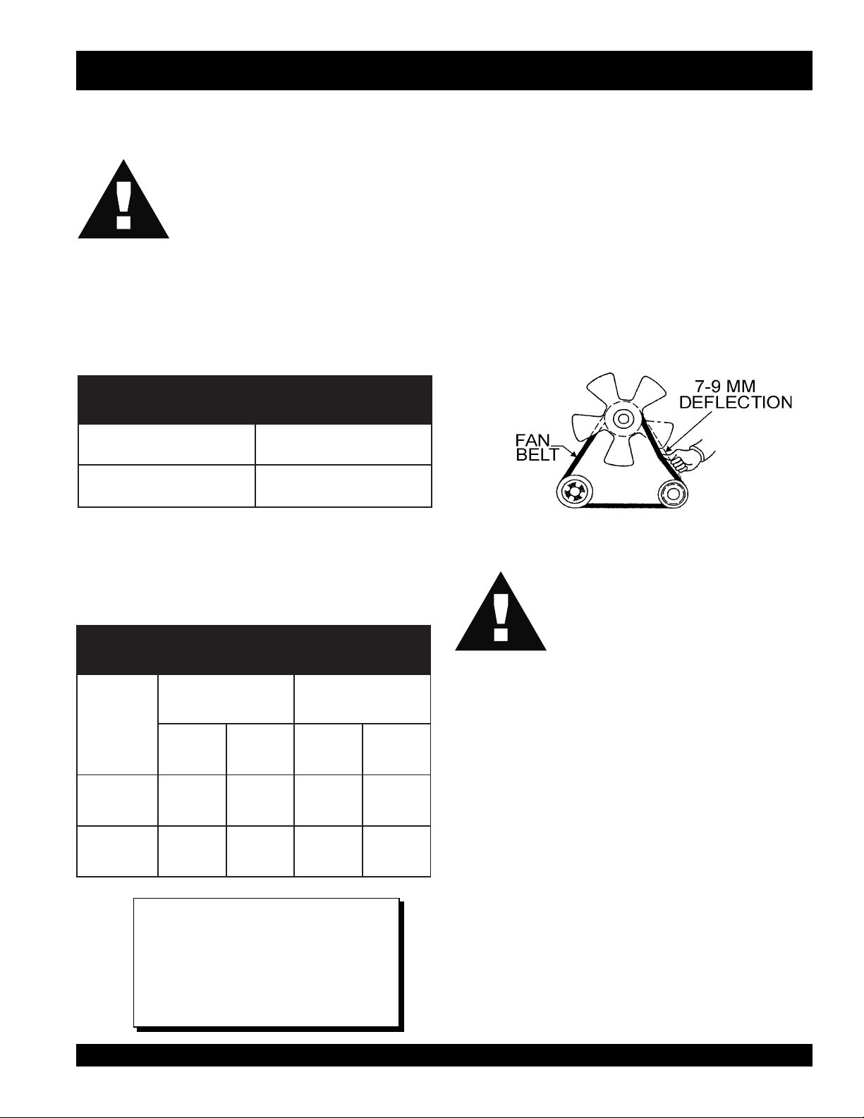
Fan Belt Tension
A slack fan belt may contribute to overheating, or to
insufficient charging of the battery. Inspect and adjust it in
accordance with the
The fan belt tension is proper if the fan belt (Figure 5) bends
7 to 9 mm (0.28- to 0.35 in.) when depressed with the thumb
as shown in Figure 13 below.
CAUTION :
Kubota Engine Operator's ManualKubota Engine Operator's Manual
Kubota Engine Operator's Manual
Kubota Engine Operator's ManualKubota Engine Operator's Manual
Figure 13. Fan Belt Tension
Never place hands near the belts or fan
while the welder/AC generator is running.
.
serutarepmeTgnitarepOezeerF-itnA.01elbaT
Air Cleaner
tnioPgnizeerFtnioPgnilioB
%loV
ezeerF-itnA
C° F° C° F°
0442-21-601222
0573-43-801622
NOTE
When the antifreeze is mixed withWhen the antifreeze is mixed with
When the antifreeze is mixed with
When the antifreeze is mixed withWhen the antifreeze is mixed with
ww
aterater
, the antifreez, the antifreez
w
ater
, the antifreez
ww
aterater
, the antifreez, the antifreez
be less than 50%.be less than 50%.
be less than 50%.
be less than 50%.be less than 50%.
SGW-250SS DC WELDER/AC GENERATOR — PARTS & OPERATION MANUAL — REV. #2 (08/08/01) — PAGE 25
e mixing re mixing r
e mixing r
e mixing re mixing r
atio matio m
atio m
atio matio m
ustust
ust
ustust
Periodic cleaning/replacement is necessary. Inspect it in
KK
accordance with the
Battery
This unit is of negative ground. DO NOT connect in reverse.
Always maintain battery fluid level between the specified
marks. Battery life will be shortened, if the fluid level is not
properly maintained. Add only distilled water when
replenishment is necessary.
The battery is sufficiently charged if the specific gravity of
the battery fluid is 1.28 (at 68° F). If the specific gravity
should fall to 1.245 or lower, it indicates that the battery is
dead and needs to be recharged or replaced.
Check to see whether the battery cables are loose. Poor
contact may result in poor starting or malfunctions, always
keep the terminals firmly tightened. Coating the terminals
with a thin film of grease will help to inhibit corrosion.
obota Engine Operobota Engine Oper
K
obota Engine Oper
KK
obota Engine Operobota Engine Oper
ator's Manator's Man
ator's Man
ator's Manator's Man
ual.ual.
ual.
ual.ual.
Page 26

SGW-250SS — INSTRUMENTATION
CAUTION :
When using a combination of dual
receptacles, total load should not exceed
the rated capacity of the generating set.
Power Outlets
The generator has the following 60 Hz, 120/240 volt singlephase receptacles.
zz
z
Single Phase
zz
One Duplex NEMA (GFCI) 5-20R (120V, 20 Amp)
One Twist Lock NEMA L5-30R (120V, 25 Amp)
One Twist Lock NEMA L14-30R (120/240V, 25 Amp)
Main Circuit Breaker (2-Pole)
This 2-pole 25 amp breaker protects the generator from short
circuiting or overloading from the 60 Hz single phase load.
Idle Control Switch
The unit is provided with an automatic idle control for noise
suppression and fuel cost reduction. The automatic idle
control automatically engages under a no-load condition.
With the automatic idle control switched “ON”, the engine
revolutions will automatically drop to about 2100 rpm (lowspeed operation) within 7 seconds after the welding stops.
When welding is resumed, the engine speed is automatically
increased to about 3600 rpm (high-speed operation) as soon
as the electrode contacts the base metal
This provides for smooth welding operation. With AC loads
of more than 100W (such as lighting equipment, motorpowered tools, submersible water pumps, etc.), the engine
runs at high speed. When a no load condition is produced,
the engine automatically shows down.
Turn the idle control switch to the “ON” (up) position when
the welder or AC loads of more than 100W is connected.
Turn the idle control switch to the “OFF” (down) position
when AC loads of less than 100W or when a magnetic switch
is used.
Fuel Gauge
GFCI Protection Breaker (Single-Pole)
This Single-pole 25 amp breaker protects the GFCI
receptacle from short circuiting or overloading from the 60
Hz single phase load.
The fuel gauge is located on the fuel tank and allows easy
monitoring of the fuel level.
GFCI Receptacle
Before connecting a load to the generator's GFCI receptacle,
push push
push
the "Test Button" on the front of receptacle before
push push
connecting the load, to confirm that the receptacle is
functioning correctly.
PAGE 26 — SGW-250SS DC WELDER/AC GENERATOR— PARTS & OPERATION MANUAL — REV. #2 (08/08/01)
Page 27
SGW-250SS — LOAD APPLICATION
Single Phase Load
Always be sure to check the nameplate on the generator
and equipment to insure the wattage, amperage and
frequency requirements are satisfactorily supplied by the
generator for operating the equipment.
Generally, the wattage listed on the nameplate of the
equipment is its rated output. Equipment may require 130—
150% more wattage than the rating on the nameplate, as
the wattage is influenced by the efficiency, power factor and
starting system of the equipment.
NOTE
If wattage is not given on the
equipment's name plate, approximate
wattage may be determined by
multiplying nameplate voltage by the
nameplate amperage.
WATTS = VOLTAGE x AMPERAGE
The power factor of this generator is 1.0. See Table 5. below
when connecting loads.
daoLyBrotcaFrewoP.11elbaT
daoLfOepyTrotcaFrewoP
srotomnoitcudniesahp-elgniS57.0-4.0
spmaltnecsednacni,sretaehcirtcelE0.1
spmalyrucrem,spmaltnecseroulF9.0-4.0
tnempiuqenoitacinummoc,secivedcinortcelE0.1
CAUTION:
cannot carry the required load can cause a voltage drop
which can burn out the appliance or tool and overheat the
cable.
The idle control is operated at minimum load capacity of
100W. If the load capacity is less than 100W, place the idle
control switch to the OFF position.
CAUTION:
Motors and motor-driven equipment draw
much greater current for starting than
during operation.
An inadequate size connecting cable which
Before connecting this generator to any
building’s electrical system, a licensed
electrician must install an isolation
(transfer) switch. Serious injury or death
may result without this transfer switch.
z
When connecting a resistance load such as an
incandescent lamp or electric heater, a capacity of up
to the generating set’s rated output (kW) can be used.
z
When connecting a fluorescent or mercury lamp, a
capacity of up to the generating set’s rated output (kW)
multiplied by 0.6 can be used.
z
When connecting an electric drill or other power tools,
pay close attention to the required starting current
capacity.
When connecting ordinary power tools, a capacity of up to
the generating set’s rated output (kW) multiplied by 0.8 can
be used.
SGW-250SS DC WELDER/AC GENERATOR — PARTS & OPERATION MANUAL — REV. #2 (08/08/01) — PAGE 27
Page 28
SGW-250SS — WELDER OPERATING INSTRUCTIONS
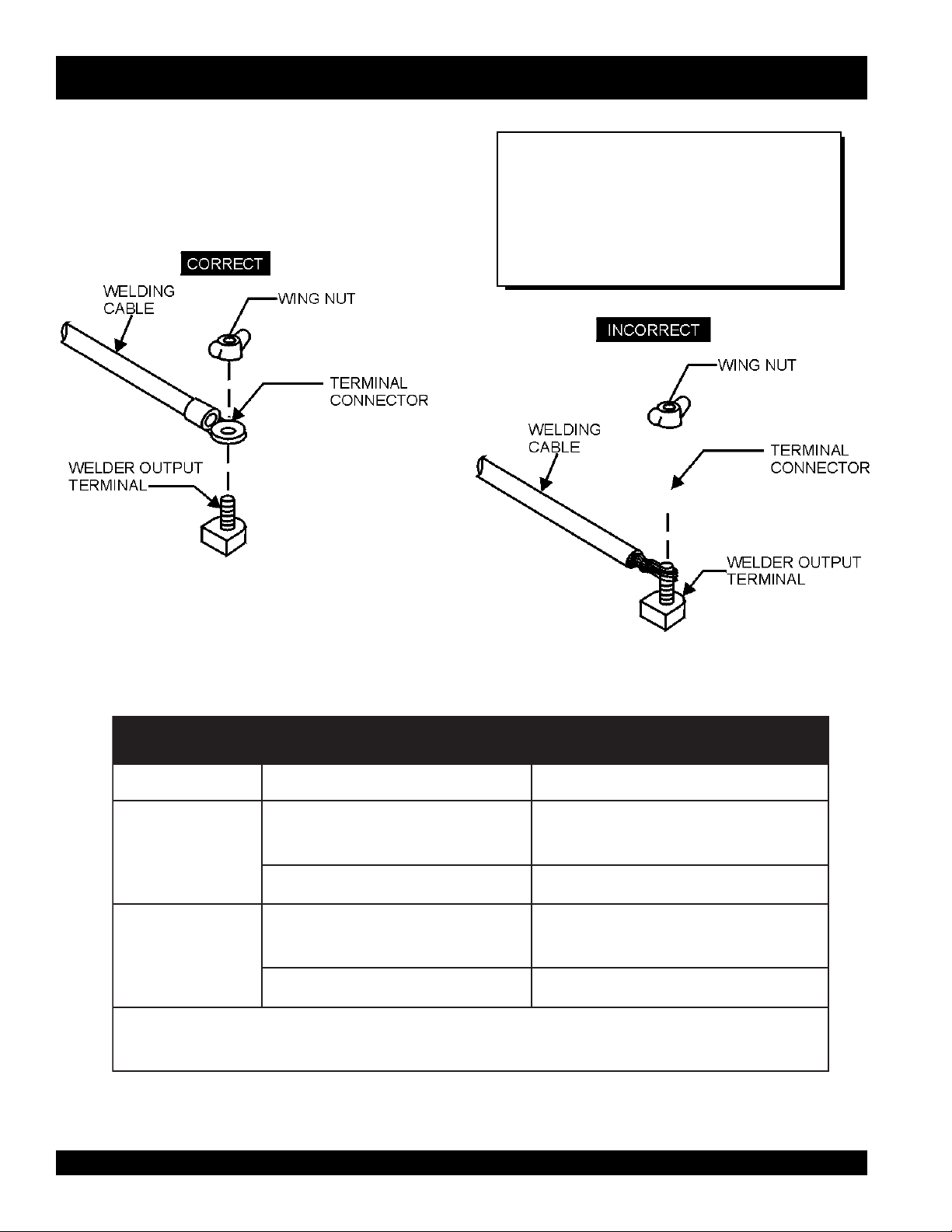
Welding Cables and Polarities
Connect the welding cables (Figure 8) to the welder's output
terminals located on the control panel. The output terminals
have positive(+) and negative(-) polarities. Select the
appropriate polarities according to the application (See Welding
Application, Table 6).
NOTE
Attach terminal connectors at the end
of each cable. NEVER connect
exposed wires (Figure 9) directly to the
terminal. Exposed wiring may cause
shocks or di-electric breakdown from
poor contact.
Figure 8. Welding Cable Connection
(Correct)
YTIRALOPDOHTEMGNIDLEWSNOITACILPPALACIPYT
...
)+(
ytiraloPthgiartS
ytiraloPesreveR
...
)+(
pmalCdnuorG
redloHedortcelE...)-(yollareppocrofgnidlewcrA
pmalCdnuorG...)+(
redloHedortcelEleetssselniatsfognidlewcrA
.rerutcafunameriwehtmorfsnoitcurtsni
Figure 9. Welding Cable Connection
(Incorrect)
snoitacilppAgnidleW.21elbaT
larenegrofslairetamleetsgnidleW
.setalpssenkcihtdna,serutcurts
fognidlewCRA,gnidlewpu-dliuB
setalpniht
ehtwollof,scitretcarahcVCehtniytiralopehtfonoitcelesehtgnidraugeR:etoN
PAGE 28 — SGW-250SS DC WELDER/AC GENERATOR— PARTS & OPERATION MANUAL — REV. #2 (08/08/01)
Page 29

SGW-250SS — WELDER OPERATING INSTRUCTIONS
CAUTION :
NEVERNEVER
NEVER
NEVERNEVER
SwitchSwitch
Switch
SwitchSwitch
When switching a selector switch, fully
rotate it to the right or left position.
1. Turn the CV/CC
(Figure 10) to the
VV
oltage Control oltage Control
the
V
oltage Control
VV
oltage Control oltage Control
Figure 10. Welding Voltage Adjustment
When the CV/CC
Current Control Current Control
Current Control
the
Current Control Current Control
SwitchSwitch
functions are inoperative.
Switch
SwitchSwitch
switch the CV/CC
during any welding operation.
CVCV
CV
position, and adjust voltage using
CVCV
knob.
NOTE
Selector Switch Selector Switch
Selector Switch
Selector Switch Selector Switch
,
and
is in the CV position,
Current Range SelectorCurrent Range Selector
Current Range Selector
Current Range SelectorCurrent Range Selector
SelectorSelector
Selector
SelectorSelector
Selector SwitchSelector Switch
Selector Switch
Selector SwitchSelector Switch
NOTE
When the CV/CC
VV
oltage Control oltage Control
V
oltage Control
the
VV
oltage Control oltage Control
3. Set the
Selector Switch Selector Switch
Selector Switch
Selector Switch Selector Switch
function is inoperative.
CCCC
Current Range Selector Switch Current Range Selector Switch
CC
Current Range Selector Switch
CCCC
Current Range Selector Switch Current Range Selector Switch
is in the CC position,
to the
desired position (Low/High).
4. Adjust current output, by setting
Current Control Current Control
Current Control
Current Control Current Control
knob
to desired current output.
NOTE
When using the
output, the outer scale is for the high range, and the inner
scale is for the low range.
Current ControlCurrent Control
Current Control
Current ControlCurrent Control
knob to adjust the current
Auxiliary AC Power
The Auxiliary AC power in most cases will not be affected
by the CV/CC Selector Switch or any controls (Figure 12)
on the front panel, and will supply a stable constant AC
voltage except when the welding mode is activated.
2. Turn the CV/CC
Selector SwitchSelector Switch
Selector Switch
Selector SwitchSelector Switch
(Figure 11) to the
CCCC
CC
CCCC
position.
Figure 12. Auxilliary AC Power
NOTE
When welding, remember that the output of the AC
AUXILIARY POWER is affected by the welding
operation. See next page for generator output voltage
Figure 11. Welding Current Adjustment
SGW-250SS DC WELDER/AC GENERATOR — PARTS & OPERATION MANUAL — REV. #2 (08/08/01) — PAGE 29
conditions when welding.
Page 30

SGW-250SS — WELDER OPERATING INSTRUCTIONS
Welding and Auxiliary Outputs.
The welding and auxiliary outputs can be used simultaneously,
subject to all of the following conditions:
z
CC/CV Selector Switch is in the CC mode.
z
CC Current Range Selector is in the low mode.
z
Current Control is in the MAX position.
NOTE
Under the above conditions, the welder can
supply welding current of 120 amps, and
AC current up to 3 kW at 120V and 240V.
Duty Cycle
The welder is rated at 100% duty cycle at 250 amps.
However the duty cycle depends upon the welding
current. Select the appropriate duty cycle from Table 7
to prevent overload.
NOTE
The 250 amp, 60% duty cycle referenced in
Table 7 is for CV welding ONLY.
elcyCytuD.31elbaT
)%(elcyCytuD0010806
)spmA(tnerruCsselro002522052
PAGE 30 — SGW-250SS DC WELDER/AC GENERATOR— PARTS & OPERATION MANUAL — REV. #2 (08/08/01)
Page 31

SGW-250SS — ENGINE OPERATING INSTRUCTIONS
WARNING:
The engine's exhaust contains harmful
ALAL
WW
AA
YS YS
emissions.
exhaust when operating inside tunnels,
excavations or buildings. Direct exhaust
away from nearby personnel.
Before Starting
1. Be sure to disconnect the electrical load and switch the
main circuit breaker to the “OFF” position prior to starting
the engine.
2. Never start the engine with the main circuit breaker “ON”.
3. Check the lubricating oil level prior to starting the engine.
Make sure the generator is level. The oil level must be
maintained between two notches on the dipstick.
4. When there is not enough lubricating oil, fill the
crankcase with high grade motor oil. Use a high quality
detergent oil classified CC or higher (See Table 3 on
page 16).
5. Check the coolant level in the radiator and subtank.
Replenish with antifreeze as necessary. Always maintain
the coolant level between the FULL and LOW markings
on the coolant container. Be sure that the radiator cap
is fastened securely.
AL
ALAL
W
WW
ventilate the
A
YS
AA
YS YS
CAUTION:
z
Check the fuel level on the fuel gauge.
When fuel is low, fill the fuel tank with
clean fresh unleaded automotive
gasoline.
CAUTION:
6. Let the engine idle for five minutes with the Automatic
Idle Control switch in the “ON” position.
7. Check the engine for abnormal vibrations, noises and
oil leakage.
8. Check the generator's output voltage by connecting an
AC voltmeter to the 120/240 volt output receptacles. If
the voltmeter indicates 120 volts, then 120 VAC can be
obtained from the 120 V and 240V receptacles at the
same time.
9. Turn the
or “ON” for full engine operation.
Shutdown
1. Remove the load from the generator, then place both
the main and GFCI circuit breakers to the OFF position.
2. Listen for the engine speed to drop. Run at low speed
for 3-5 minutes.
3. Stop the engine by setting the ON/OFF switch on the
generator's front panel to the OFF position.
STST
ARAR
TT
ST
AR
NEVER press the the “
switch while the engine is running.
AA
utomatic Idle Control Switch utomatic Idle Control Switch
A
utomatic Idle Control Switch
AA
utomatic Idle Control Switch utomatic Idle Control Switch
T
STST
ARAR
TT
to either “OFF”
” push-button
z
If gasoline spillage occurs, completely
Starting
1. On the front panel of the generator, set the ON/OFF
switch to the ON position (up).
2. Pull the choke knob half way out (half open).
3. Press and hold the start “push-button” switch until the
engine starts, then release.
4. After the engine starts gradually push the choke knob
inward, all the way back to its closed position.
5. If the engine does not start within 10 seconds after
pushing start button, wait about 30 seconds and repeat
steps 1 through 4. If the engine fails to start after repeated
attempts, refer to Table 8, Engine Troubleshooting.
SGW-250SS DC WELDER/AC GENERATOR — PARTS & OPERATION MANUAL — REV. #2 (08/08/01) — PAGE 31
wipe up the spilled gasoline.
Page 32

SGW-250SS — MAINTENANCE
General Inspection
At least daily or prior to each use, the welder/AC generator
should be cleaned and inspected for deficiencies. Check for
loose, missing or damaged nuts, bolts or other fasteners.
Also check for fuel or oil leaks.
Engine Side:
For a more detail engine maintenance schedule refer to the
HONDHOND
A Engine OperA Engine Oper
HOND
A Engine Oper
HONDHOND
A Engine OperA Engine Oper
Air Cleaner:
Every 50 hours: Remove air cleaner element by removing
the wing bolts and screws. Inspect and clean heavy duty
paper element by tapping it several times or blow with
compressed air (not to exceed 30 psi). If element is too
dirty or damaged, replace. Clean foam element with liquid
detergent and hot water or with kerosene. Wrap foam element
in a cloth and squeeze dry. Wipe any dirt from the inside of
the air cleaner body and cover using a moist rag. Be careful
to prevent dirt from entering the air chamber that leads to
the carburetor.
Place the foam air filter element to the air cleaner body. Be
sure the gaskets are in place, then reinstall the paper air
filter element and cover. Tighten the air filter wing bolt
securely.
ator's Manator's Man
ator's Man
ator's Manator's Man
ualual
ual
ualual
.
Removing Water from the Fuel ank
After prolonged use, water and other impurities accumulate in the bottom of the fuel tank. Occasionally remove
the drain cock and drain the contents. During cold
weather, the more empty are inside the tank, the easier it
is for water to accumulate inside the tank. This can be
reduced by always keeping the fuel tank as full as possible.
Fuel Addition
Always add clean, fresh unleaded fuel. Always pour
through mesh lining.
Rectifier Fins
Periodically inspect the rectifier fins for contamination.
ALWAYS keep fins free of dirt.
Air Removal
If air enters the fuel system of a gasoline engine, starting
becomes impossible. After running out of gasoline, or
after disassembling the fuel system, bleed the system by
following this procedure:
Turn the operation switch to the ‘ON’ position for 15-30
seconds. Try again, if needed.
Cleaning the Fuel Strainer
Clean the fuel strainer if it contains dust or water. Remove
dust or water in the strainer cap and wash it in gasoline.
Securely fasten the fuel strainer cap so that fuel will not
leak. Check the fuel strainer every 200 hours of operation or
once a month.
PAGE 32 — SGW-250SS DC WELDER/AC GENERATOR— PARTS & OPERATION MANUAL — REV. #2 (08/08/01)
Page 33

SDW-225SS — MAINTENANCE
SGW-250SS — MAINTENANCE
ECNANETNIAM/NOITCEPSNI
sleveLdiulFenignEkcehC X
renaelCriAkcehC X
leveLdicAyrettaBkcehC X
noitidnoCtleBnaFkcehC X
skaeLrofkcehC X
straPfogninesooLrofkcehC X
1
*retliFdnaliOenignEecalpeR
ENIGNE
retliFriAnaelC X
knaTleuFfomottoBniarD X
edistuOdnaedisnI,tinUnaelC X
2
*retliFleuFegnahC
leveLnoitcetorPtnalooCkcehCdnarotaidaRnaelC X
tnemelEretliFriAecalpeR
spmalCdnasesoHllakcehC
knaTleuFfoedisnInaelC
YLIADsrH01 srH052 srH005
X
X
srH0001
X
X
X
ROTARENEG
1
*
2
*
smhoM3revOecnatsiseRnoitalusnIerusaeM X
.ylnoemittsrif,sruoh001taretlifdnalioenigneecalpeR
.ylnoemittsrif,sruoh052taretlifleufecalpeR
SGW-250SS DC WELDER/AC GENERATOR — PARTS & OPERATION MANUAL — REV. #2 (08/08/01) — PAGE 33
Page 34

SGW-250SS — PREPARATION FOR LONG -TERM STORAGE
Welder/Generator Storage
For storage of the generating set for over 30 days, the
following is required:
z
Drain the fuel tank completely.
z
Run the engine until the gasoline in the carburetor is
completely consumed.
z
Completely drain the oil from the crankcase and refill
with fresh oil.
z
Remove the spark plug, pour 2 or 3 cc of SAE 30 oil
into the cylinder and crank slowly to distribute the oil.
z
Slowly rotate the engine a few times with the and install
a new plug.
z
Remove the NEGATIVE battery cable from the negative
post on the battery.
z
Stop the engine at the compression point.
z
Clean all external parts of the generating set with a cloth.
z
Cover the generating set and store in a clean, dry place.
PAGE 34 — SGW-250SS DC WELDER/AC GENERATOR— PARTS & OPERATION MANUAL — REV. #2 (08/08/01)
Page 35

SGW-250SS —ENGINE/GENERATOR WIRING DIAGRAM
SGW-250SS DC WELDER/AC GENERATOR — PARTS & OPERATION MANUAL — REV. #2 (08/08/01) — PAGE 35
Page 36

SGW-250SS — TROUBLESHOOTING (WELDER)
Practically all breakdowns can be prevented by proper
handling and maintenance inspections, but in the event of
a breakdown, please take a remedial action following the
diagnosis based on the Welder Troubleshooting (Table 8)
information shown below. If the problem cannot be remedied,
please consult our company's business office or service
plant.
MOTPMYS MELBORPELBISSOP NOITULOS
?deepswoL .noitces"deepswoltasniamerenignE"otrefeR
?)R(rotsiserevitcefeD .rotsiserecalpeR
s'rotarenegnitneserptonsiegatlovCA
.noitcesgnidlewronoitcesCA
CAniegatlovwoldnagnidlewrooP
.noitcesrewop
?rotorevitcefeD .rotorecalpeR
?3FesufnwolB .esufecalpeR
?rotorevitcefeD .rotorecalpeR
?deepswoL .noitces"deepswoltasniamerenignE"otrefeR
?gnidniw
?rellortnoCdleiFevitcefeD ."rellortnoCdleiF"ecalpeR
?gniriWevitcefeD .gniriwriapeR
?rellortnoCdleiFevitcefeD ."rellortnoCdleiF"ecalpeR
erutamranitiucric-trohsreyaL
GNITOOHSELBUORTREDLEW.41ELBAT
.erutamraecalpeR
?gniriwevitcefeD .gniriwriapeR
?rellortnoCdleiFevitcefeD ."rellortnoCdleiF"ecalpeR
?)eR(reifitcerevitcefeD .reifitcerecalpeR
onsierehttubtublamronsirewopCA
egatlovdnatnerruC.ytilibapacgnidlew
.evitarepo-nierastnemtsujda
,desuebtonnacrowolootsirewopCA
.lamronsignidlewtub
.noosootsegrahcsidyrettaB `?rotalugerenigneevitcefeD .rotalugerecalpeR
.elbacgnidlew
?gnidniw
?gniriwevitcefeD .gniriwriapeR
?sehctiwsrotcelesevitcefeD .2Sro1SecalpeR
rekaerbtiucricevitcefeD .rekaerbtiucricecalpeR
?)edisCA(
?gniriwevitcefeD .gniriwriapeR
?rellortnoCdleiFevitcefeD ."rellortnoCdleiF"ecalpeR
?remrofsnarttnerrucevitcefeD .3TCro2TC,1TC,remrofsnartecalpeR
?)2Lro1LroLCD(rotcaerevitcefeD .rotcaerecalpeR
fossenkcihtdnahtgneletauqedanI
erutamranitiucric-trohsreyaL
gnidniwerutamranitiucric-trohsreyaL
.elbacgnidlewecalpeR
.erutamraecalpeR
.erutamraecalpeR
?gniriwevitcefeD .gniriwriapeR
?hctiwsnoitingievitcefeD .hctiwsnoitingiecalpeR
PAGE 36 — SGW-250SS DC WELDER/AC GENERATOR— PARTS & OPERATION MANUAL — REV. #2 (08/08/01)
Page 37

SGW-250SS — TROUBLESHOOTING (ENGINE)
Practically all breakdowns can be prevented by proper
handling and maintenance inspections, but in the event of
a breakdown, please take a remedial action following the
MOTPMYS MELBORPELBISSOP NOITULOS
?leufoN .leufhsinelpeR
?metsysleufehtniriA .metsysdeelB
?deggolcepipleuF .epipleufnaelC
?deggolcretlifleuF .retlifleufegnahcronaelC
?erutarepmet
enatecwolhtiwleuF
?rebmun
diagnosis based on the Engine Troubleshooting (Table 9)
shown below. If the problem cannot be remedied, please
consult our company's business office or service plant.
?metsysleufehtniretaW .knatleufmorfretawevomeR
ytisocsivhgihylevissecxE
woltalioenigneroleuffo
)1TRAP(GNITOOHSELBUORTENIGNE.51ELBAT
.lioenigneroleufdeificepsehtesU
.leufdeificepsehtesU
esooloteudkaelleuF
?tungniniaterepipnoitcejni
.tratstonseodenignE
pmupnoitcejnI
?gninoitcnuflam
?gniraebrorenil
?rednilyc
?gnimitnoitcejnitcerrocnI .tsujdA
?nrowtfahsmacleuF .ecalpeR
?deggolcelzzonnoitcejnI .elzzonnoitcejninaelC
,tfahsknarcfoeruzieS
rednilyc,notsip,tfahsmac
morfkaelnoisserpmoC
?gnimitevlavreporpmI .raeggnimitecalperrotcerroC
?nrowrenildnagnirnotsiP .ecalpeR
?ecnaraelcevlavevissecxE .tsujdA
.tunnethgiT
.ecalperroriapeR
.ecalperroriapeR
wolg,tlobdaehrednilycnethgit,teksagdaehecalpeR
.redlohelzzondnagulp
SGW-250SS DC WELDER/AC GENERATOR — PARTS & OPERATION MANUAL — REV. #2 (08/08/01) — PAGE 37
Page 38

SGW-250SS — TROUBLESHOOTING (ENGINE)
MOTPMYS MELBORPELBISSOP NOITULOS
?ytridrodeggolcretlifleuF .egnahcronaelC
?deggolcrenaelcriA .egnahcronaelC
)2TRAP(GNITOOHSELBUORTENIGNE.51ELBAT
esooloteudkaelleuF
?tungniniaterepipnoitcejni
pmupnoitcejnI
?gninoitcnuflam
.htooms
tonsinoituloverenignE
?erusserp
?deggolc
?deggolc
.devresbosisag
tsuahxeeulbroetihwrehtiE
?kcutsro
gninepoelzzontcerrocnI
rokcutselzzonnoitcejnI
epipwolfrevoleuF
?gninoitcnuflamronrevoG .riapeR
?lioenigneevissecxE .leveldeificepsehtotecudeR
nrowrenildnagnirnotsiP
?gnimitnoitcejnitcerrocnI .tsujdA
?noisserpmoctneicifeD .ecnaraelcpottsujdA
.tunnethgiT
.ecalperroriapeR
.tsujdA
.ecalperroriapeR
.naelC
.ecalperroriapeR
?daolrevO .daolehtnesseL
?desuleufedargwoL .leufdeificepsehtesU
yargkradrokcalbrehtiE
.devresbosisagtsuahxe
.tuptuotneicifeD
PAGE 38 — SGW-250SS DC WELDER/AC GENERATOR— PARTS & OPERATION MANUAL — REV. #2 (08/08/01)
?deggolcretlifleuF .egnahcronaelC
?deggolcrenaelcriA .egnahcronaelC
?noitcejnielzzontneicifeD .elzzonehtecalperroriapeR
?gnimitnoitcejnitcerrocnI .tsujdA
strapgnivoms'enignE
?gniziesebotmees
?noitcejnileufnevenU .pmupnoitcejniehtecalperroriapeR
?noitcejnielzzontneicifeD .elzzonehtecalperroriapeR
?kaelnoisserpmoC
.ecalperroriapeR
wolg,tlobdaehrednilycnethgit,teksagdaehecalpeR
.redlohelzzondnagulp
Page 39

SGW-250SS — TROUBLESHOOTING (ENGINE)
MOTPMYSMELBORPELBISSOPNOITULOS
?tiucrictaeh-erpnekorB.tiucrictaeh-erpkcehC
retratsdnatratsotsliafenignE
.setator
woltasniamerdnastratsenignE
.deeps
.nurtonseodretratS ?degrahcsidyrettaB .yrettabegrahC
?leufoN.leufddA
?gniriwevitcefeD.gniriwkcehC
?reniartsleufdeggolC.ecalperronaelC
?renaelcriadeggolC.ecalperronaelC
?gniriwdetcennocsiD.gniriwriaperdnakcehC
?gninoitcnuflamretratS .ecalperroriapeR
?gninoitcnuflamhctiwsyeK .ecalperroriapeR
?detcennocsidgniriW .gniriwtcennoC
?tuodenrub5FesuF.esufecalpeR
)3TRAP(GNITOOHSELBUORTENIGNE.51ELBAT
rewopCAnitneserpegatlovoN
?ecruos
?rotorevitcefeD.rotorecalpeR
egatlovondnasesirdeepsenignE
.ecruosrewopCAnitneserpsi
?gnidniw
rewopCAdnasesirdeepsenignE
ebtonnacrowolootsiegatlov
.desu
yrettabdnasesirdeepsenignE
.noosootsegrahcsid
enignednasesirdeepsenignE
.dedaolrevosmees
lortnoCeldI"dnastratsenignE
enignE.noitisopFFOnisi"hctiwS
egralsahenignednasesirdeeps
.sdaolrevO.snoitarbiv
lortnoCeldI"dnastratsenignE
enignE.noitisopFFOnisi"hctiwS
sahenignednasesirdeeps
.esionlamronba
?retemtlovevitcefeD.retemtlovecalpeR
?gniriwdetcennocsiD.gniriwriaperdnakcehC
erutamranitiucric-trohsreyaL
?)rotcetorp(rekaerbtiucricevitcefeD .)rotcetorp(rekaerbtiucricecalpeR
niseriwnekorb,tiucric-trohsreyaL
?gnidniwerutamra
?rotalugerenigneevitcefeD.rotalugerecalpeR
?gniriwevitcefeD.gniriwecalperroriapeR
?rotanretlaevitcefeD.rotanretlaecalperroriapeR
?gniraebrotanretladegamaD.sgniraebrotanretlaecalpeR
?noitallatsnienignedaB.enignefonoitallatsnitaepeR
?strapenigneesooL .senthgitrofstrapenignellakcehC
?rotanretlaevitcefeD esoolrogniraebdegamadrofrotanretlakcehC
.)1ER(reifitcerecalpeR
.erutamraecalpeR
.erutamraecalperroriapeR
.stlobgnipmalc
?erusolcneevitcefeD .ssenthgitrofstloberusolcnekcehC
lortnoCeldI"dnastratsenignE
enignE.noitisopFFOnisi"hctiwS
hgihtasniamerdnasesirdeeps
sihctiwslortnoCeldInehwdeeps
.noitisopNOehtnidecalp
?dionelosevitcefeD .dionelosecalpeR
?yalerevitcefeD .yalerecalpeR
?ecivedlortnoceldievitcefeD .ecivedlortnoceldiecalperroriapeR
?hctiwslortnoceldievitcefeD .hctiwslortnoceldiecalpeR
SGW-250SS DC WELDER/AC GENERATOR — PARTS & OPERATION MANUAL — REV. #2 (08/08/01) — PAGE 39
Page 40

EXPLANATION OF CODE IN REMARKS COLUMN
How to read the marks and remarks used in this parts
book.
Items Found In the “Remarks” Column
Serial Numbers-Where indicated, this indicates a serial
number range (inclusive) where a particular part is used.
Model Number-Where indicated, this shows that the
corresponding part is utilized only with this specific model
number or model number variant.
Items Found In the “Items Number” Column
All parts with same symbol in the number column,
■
, belong to the same assembly or kit.
or
Note: If more than one of the same reference number is listed,
the last one listed indicates newest (or latest) part available.
NOTE
The contents of this parts catalog areThe contents of this parts catalog are
The contents of this parts catalog are
The contents of this parts catalog areThe contents of this parts catalog are
subject to change without notice.subject to change without notice.
subject to change without notice.
subject to change without notice.subject to change without notice.
, #, +, %,
*
PAGE 40 — SGW-250SS DC WELDER/AC GENERATOR— PARTS & OPERATION MANUAL — REV. #2 (08/08/01)
Page 41

SGW-250SS — SUGGESTED SPARE PARTS
SGW SGW
SGW
SGW SGW
Qty. P/N Description
5 ......... 17010ZJ1000 ... AIR FILTER
1 ......... 17218ZJ1000 ... AIR FILTER, OUTER
5 ......... 16910ZE8015 .. FUEL FILTER
5 ......... 15400PR3004 .. OIL FILTER
1 ......... 15427ZJ1000 ... SCREEN, CRANKCASE OIL FILTER
1 ......... 35480ZJ1812 ... SWITCH ASSY., OIL LEVEL
1 ......... 0601200102 ..... STARTER SWITCH
1 ......... 0810105800 ..... FUEL CAP
1 ......... 0601805331 ..... MAIN CIRCUIT BREAKER
1 ......... 0601827399 ..... CONTROL UNIT
1 ......... 1620150404 ..... SOLENOID, ROTARY
4 ......... 9807952876 ..... SPARK PLUG
2 ......... 0601821370 ..... RECTIFIER
1 ......... 0601831841 ..... CV/CC SELECTOR SWITCH
1 ......... 0601803070 ..... CC CURRENT RANGE SELECT. SW
2 ......... D1233000004 .. OUTPUT TERMINAL
2 ......... 0801880004 ..... INSULATOR WASHER
4 ......... 0039510000 ..... HEX NUT
4 ......... 0045110000 ..... LOCK WASHER
4 ......... 0042710000 ..... PLAIN WASHER
2 ......... 0037810000 ..... WING NUT
1 ......... 0601803117 ..... KNOB, SELECTOR SWITCHES
1 ......... A6356400303 .. THROTTLE WIRE
1 ......... 0602125032 ..... FUEL GAUGE
1 ......... 31740ZJ7003 ... DIODE ASSY., ENGINE STOP
W/HONDW/HOND
W/HOND
W/HONDW/HOND
A GX610 AIR-COOLED ENGINE 1 A GX610 AIR-COOLED ENGINE 1
A GX610 AIR-COOLED ENGINE 1
A GX610 AIR-COOLED ENGINE 1 A GX610 AIR-COOLED ENGINE 1
TT
O 3 UNITSO 3 UNITS
T
O 3 UNITS
TT
O 3 UNITSO 3 UNITS
SGW-250SS DC WELDER/AC GENERATOR — PARTS & OPERATION MANUAL — REV. #2 (08/08/01) — PAGE 41
Page 42

GENERATOR ASSY.
SGW-250SS — GENERATOR ASSY.
PAGE 42 — SGW-250SS DC WELDER/AC GENERATOR— PARTS & OPERATION MANUAL — REV. #2 (08/08/01)
Page 43

SGW-250SS — GENERATOR ASSY.
GENERATOR ASSY.
NO PART NO PART NAME QTY. REMARKS
1 D2110100003 ROTOR ASSY .......................... 1 .......... INCLUDES ITEMS W/
1-1
*
1-2
*
1-3
*
1-4
*
2 D2113400004 SET BOLT ROTOR 1
3 0801086104 SET WASHER BEARING 1
4 D2113100004 FAN 1
5 0040010000 LOCK WASHER 1
6 D2155100202 END BRACKET 1
7 D2134000803 ARMATURE ASSY 1
8 D2155000104 END BRACKET 1
9 D2137000203 FIELD ASSY EXCITER 1
10 011606025 HEX HEAD BOLT ..................... 4 .......... REPLACES 0017106025
11 1961324003 GROMMET 1
12 D2133300004 COVER 1
13 D2131500404 SET BOLT 4
14 0040010000 LOCK WASHER 4
15 031110160 PLAIN WASHER....................... 4.......... REPLACES 0041210000
16 D1153500603 COVER 2
17 D11535005031 COVER 2
18 D2155500013 COVER 1
19 011006010 HEX HEAD BOLT ..................... 4 .......... REPLACES 0017106010
20 1961844513 FIN 4
21 0601820012 RECTIFIER .............................. 2 .......... SR30MA- 6S
22 0601820013 RECTIFIER .............................. 2 .......... SR30MA-6R
23 0017105016 HEX HEAD BOLT 16
24 103189004 INSULATOR WASHER 16
25 011208035 HEX HEAD BOLT ..................... 6 .......... REPLACES 0017108035
26 D2185300004 SET BOLT 2
27 0040008000 LOCK WASHER 2
28 031108160 PLAIN WASHER....................... 2.......... REPLACES 0041208000
29 0019008016 HEX HEAD BOLT 4
30 020108060 HEX NUT ..................................4 .......... REPLACES 0207208000
31 1991843504 CONNECTION PLATE 2
32 1001843504 CONNECTION PLATE 12
33 D2155400004 COVER FAN 1
34 02072080000 HEX NUT 2
35 011208025 HEX HEAD BOLT ..................... 4 .......... REPLACES 0012308025
0601820037 RECTIFIER .............................. 1 .......... S10VB60
0601822638 SURGE ABSORBER ................ 1 .......... TNR15G 431K
042006304 BEARING ................................. 1 .......... 6304 DDU; REPLACES 0071206304
3051070003 FAN 1
*
SGW-250SS DC WELDER/AC GENERATOR — PARTS & OPERATION MANUAL — REV. #2 (08/08/01) — PAGE 43
Page 44

CONTROL PANEL ASSY.
SGW-250SS — CONTROL PANEL ASSY.
PAGE 44 — SGW-250SS DC WELDER/AC GENERATOR— PARTS & OPERATION MANUAL — REV. #2 (08/08/01)
Page 45

SGW-250SS — CONTROL PANEL ASSY.
CONTROL PANEL ASSY.
NO PART NO PART NAME QTY. REMARKS
1 D2205000203 CONTROL PANEL ............................................. 1 ........... D25122 00002
2 0021805020 MACHINE SCREW 4
3 0601831841 CV CC SELECTOR SWITCH ............................ 1 ........... SSK- 1831
4 0601803070 CC CURRENT RANGE SELECTOR SWITCH .. 1 ........... SSK-2036C
5 0021304015 MACHINE SCREW ........................................... 6 ........... REPLACES 0021506012
6 8705945004 SEAL 2
7 0601840095 RHEOSTAT CURRENT CONTROL ................... 1 ........... RV24YN20SB2KO
8 0601840026 RHEOSTAT VOLTAGE CONTROL ..................... 1 ........... RA25YN20SB2KOJ
9 0601840103 KNOB ................................................................ 2 ........... K- 2195
10 0023304008 SET SCREW 4
11 0601805331 CIRCUIT BREAKER ......................................... 1 ........... KM52 265V 30A
12 4341817004 BRACKET CIRCUIT BREAKER 1
13 0027104015 MACHINE SCREW 2
14 0601830739 IDLE CONTROL SWITCH ................................. 1 ........... ET210N12
15 0601830796 OPERATION SWITCH ...................................... 1 ........... ET225N12
16 0601200102 STARTER SWITCH ........................................... 1 ........... ST- 403
17 0601800682 HOUR METER .................................................. 1 ........... #820114
18 0027403512 MACHINE SCREW 2
0030003500 HEX NUT 2
19 0801831204A OUTPUT TERMINAL ......................................... 2 ...........REPLACES D1233000004
20 0801880004 INSULATOR WASHER 2
21 020310080 HEX NUT ........................................................... 4 ...........REPLACES 0039510000
22 030212300 LOCK WASHER ................................................. 4 ........... REPLACES 0045110000
23 0042710000 PLAIN WASHER 4
24 0037810000 WING NUT 2
25 0601812529 RECEPTACLE................................................... 1 ........... L14- 30R
26 0601811031 RECEPTACLE................................................... 1 ........... L5- 20R
27 0601812597 RECEPTACLE................................................... 1 ........... 5- 20R
28 0021004012 MACHINE SCREW 6
0030004000 HEX NUT ........................................................... 6........... REPLACES 0207004000
29 0601806420 CIRCUIT PROTECTOR 1
30 0027103006 MACHINE SCREW 2
31 0601815109 GROUND TERMINAL ........................................ 1 ........... T- 381
32 D2238100203 COVER OUTPUT TERMINAL 1
D2238400004 RUBBER SHEET 1
33 0805088004 STAY RUBBER 1
34 0821800014 COLLAR 2
35 011206020 HEX HEAD BOLT .............................................. 2 ........... REPLACES 0016906020
0207006000 HEX NUT 2
36 0016906016 HEX HEAD BOLT 1
37 0601842462 RESISTOR ........................................................ 1 ........... GG40W35O
38 0027104012 MACHINE SCREW 2
39 0601821370 RECTIFIER ....................................................... 3 ........... DE4503
40 0027105040 MACHINE SCREW 1
SGW-250SS DC WELDER/AC GENERATOR — PARTS & OPERATION MANUAL — REV. #2 (08/08/01) — PAGE 45
Page 46

CONTROL PANEL ASSY.
SGW-250SS — CONTROL PANEL ASSY.
PAGE 46 — SGW-250SS DC WELDER/AC GENERATOR— PARTS & OPERATION MANUAL — REV. #2 (08/08/01)
Page 47

SGW-250SS — CONTROL PANEL ASSY.
CONTROL PANEL ASSY.
NO PART NO PART NAME QTY. REMARKS
41 0601804211 CURRENT TRANSFORMER ............................. 3 ........... MCT-100Y
42 0027104012 MACHINE SCREW 6
43 0601823204 RECTIFIER ....................................................... 2 ........... S5VB60
44 0027103020 MACHINE SCREW 2
45 0601827399 CONTROL UNIT ................................................ 1 ........... FD-80
46 0027105012 MACHINE SCREW 6
47 0601823707 RELAY .............................................................. 1 ........... CA1A-DC12V- N
48 0027105020 MACHINE SCREW 1
49 0601815870 TERMINAL BOARD .......................................... 1 ........... KT-20 2P
D9522001204 SYMBOL SEAL 1
50 0601815758 TERMINAL BOARD .......................................... 1 ........... KT- 30 2P
D9522000804 SYMBOL SEAL 1
51 0027105020 MACHINE SCREW 2
52 8511864601A TERMINAL PLATE ............................................. 1 ...........REPLACES 8511864604
53 0016906016 HEX HEAD BOLT 5
54 0601802137 FUSE ................................................................ 1 ........... 10A AC250V
55 0601803117 KNOB (SELECTOR SWITCHES) 2
SGW-250SS DC WELDER/AC GENERATOR — PARTS & OPERATION MANUAL — REV. #2 (08/08/01) — PAGE 47
Page 48

ELECTRIC PARTS ASSY.
SGW-250SS — ELECTRIC PARTS ASSY.
PAGE 48 — SGW-250SS DC WELDER/AC GENERATOR— PARTS & OPERATION MANUAL — REV. #2 (08/08/01)
Page 49

SGW-250SS — ELECTRIC PARTS ASSY.
ELECTRIC PARTS ASSY.
NO PART NO PART NAME QTY. REMARKS
1 D2263500303 AC REACTOR 2
2 D2263500403 DC REACTOR ..................... 1 ............... INCLUDES ITEMS W/
2-1*0601831054 THERMOSTAT ..................... 1............... REPLACES 0603210120
3 0017106016 HEX HEAD BOLT 12
4 1622636103Z ROTARY SOLENOID ...........1 ............... 7SL25-22; REPLACES 1620150404
5 1992636004 ARM SOLENOID 1
6 0050403020 SPRING PIN 1
7 0010106025 HEX HEAD BOLT 1
0030006000 HEX NUT 1
8 A6356600404 WIRE STOPPER 1
9 0017105010 HEX HEAD BOLT 1
10 D2356200003 BRACKET SOLENOID 1
11 0207006000 HEX NUT 2
12 0010106040 HEX HEAD BOLT 1
0038706000 HEX NUT 1
13 0016906016 HEX HEAD BOLT 4
14 A6356400303B THROTTLE WIRE 1
15 0017105010 HEX HEAD BOLT 1
*
SGW-250SS DC WELDER/AC GENERATOR — PARTS & OPERATION MANUAL — REV. #2 (08/08/01) — PAGE 49
Page 50

BATTERY ASSY.
SGW-250SS — BATTERY ASSY.
PAGE 50 — SGW-250SS DC WELDER/AC GENERATOR— PARTS & OPERATION MANUAL — REV. #2 (08/08/01)
Page 51

SGW-250SS — BATTERY ASSY.
BATTERY ASSY.
NO PART NO PART NAME QTY. REMARKS
1 0805081004 BATTERY SHEET .................. 1 ............ REPLACES 1702202104
2 D2345200004 BATTERY BAND 1
3 0805082704 BATTERY BOLT 2
4 0037806000 WING NUT 2
5 0040006000 LOCK WASHER 2
6 0041206000 PLAIN WASHER 2
7 0602220600 TERMINAL CAP RED 1
0602220601 TERMINAL CAP BLACK 1
8 D1343200604 TERMINAL CAP 1
SGW-250SS DC WELDER/AC GENERATOR — PARTS & OPERATION MANUAL — REV. #2 (08/08/01) — PAGE 51
Page 52

TAIL PIPE ASSY.
SGW-250SS — TAIL PIPE ASSY.
PAGE 52 — SGW-250SS DC WELDER/AC GENERATOR— PARTS & OPERATION MANUAL — REV. #2 (08/08/01)
Page 53

SGW-250SS — TAIL PIPE ASSY.
TAIL PIPE ASSY.
NO PART NO PART NAME QTY. REMARKS
1 D2335100013 OUTLET PIPE 1
2 D9102200104 PIPE BAND 1
3 0016908030 HEX HEAD BOLT 1
SGW-250SS DC WELDER/AC GENERATOR — PARTS & OPERATION MANUAL — REV. #2 (08/08/01) — PAGE 53
Page 54

FUEL TANK ASSY.
SGW-250SS — FUEL TANK ASSY.
PAGE 54 — SGW-250SS DC WELDER/AC GENERATOR— PARTS & OPERATION MANUAL — REV. #2 (08/08/01)
Page 55

SGW-250SS — FUEL TANK ASSY.
FUEL TANK ASSY.
NO PART NO PART NAME QTY. REMARKS
1 A6365000402B FUEL TANK ................................ 1 ......... INCLUDES ITEMS W/
1-1
*
1-2
*
2 3015530004 DRAIN PLUG 1
3 0150200011 O RING 1
4 0602125032 FUEL GAUGE 1
5 0016908020 HEX HEAD BOLT 4
6 0605513143 FUEL HOSE 1
7 0605515093 HOSE BAND 1
8 0605515240 HOSE BAND 1
0810105900 CAP FUEL TANK ....................... 1 ......... REPLACES 0810105800
0810105900 FUEL FILTER 1
*
SGW-250SS DC WELDER/AC GENERATOR — PARTS & OPERATION MANUAL — REV. #2 (08/08/01) — PAGE 55
Page 56

ENCLOSURE ASSY.
SGW-250SS — ENCLOSURE ASSY.
PAGE 56 — SGW-250SS DC WELDER/AC GENERATOR— PARTS & OPERATION MANUAL — REV. #2 (08/08/01)
Page 57

SGW-250SS — ENCLOSURE ASSY.
ENCLOSURE ASSY.
NO PART NO PART NAME QTY. REMARKS
1 D2415000412 BASE 1
1-1 0226900130 EDGE COVER 1
2 D2415400014 BASE COVER 1
3 0016906016 HEX HEAD BOLT 4
4 D2305100004 ENGINE BASE 1
5 D2418500104 GENERATOR BASE 1
6 0016908020 HEX HEAD BOLT 6
7 D2418700103 COMMON BASE 1
7-1 D2498000004 LINING 1
8 3025419304 RUBBER SUSPENSION 2
9 D9312600104 RUBBER SUSPENSION 2
10 0207010000 HEX NUT 8
11 0010110045 HEX HEAD BOLT 2
0207010000 HEX NUT 2
12 0017110030 HEX HEAD BOLT 2
13 D2425000413 FRONT FRAME 1
13-1 D2492200114 LINING 1
14 0016908020 HEX HEAD BOLT 4
15 D2425200104 COVER FRONT FRAME 1
16 0016906016 HEX HEAD BOLT 6
17 D2485100213 PANEL 1
17-1 D2498200013 LINING 1
18 0016908020 HEX HEAD BOLT 2
19 D2445000402 REAR FRAME 1
20 0016908020 HEX HEAD BOLT 8
21 D2445300304 COVER REAR FRAME 1
22 0016906016 HEX HEAD BOLT 5
23 0016906016 HEX HEAD BOLT 1
0040506000 TEETHED WASHER 1
24 D2455400013 COVER 1
25 0016906016 HEX HEAD BOLT 4
26 D2465000303 ROOF PANEL 1
D2498500014 LINING 1
27 0016908020 HEX HEAD BOLT 19
28 D2332300014 COVER EXHAUST PIPE 1
29 0016906016 HEX HEAD BOLT 3
THE PART NUMBER SHOWN IS TEAL. ADD THE
FOLLOWING LETTERS AFTER THE PART NUMBER
WHEN ORDERING ANY PAINTED PANEL TO INDICATE
COLOR OF UNIT:
MQW - WHITE
THE SERIAL NUMBER MAY BE REQUIRED.
SGW-250SS DC WELDER/AC GENERATOR — PARTS & OPERATION MANUAL — REV. #2 (08/08/01) — PAGE 57
Page 58

NAME PLATE AND DECALS ASSY.
SGW-250SS — NAME PLATE AND DECALS ASSY.
PAGE 58 — SGW-250SS DC WELDER/AC GENERATOR— PARTS & OPERATION MANUAL — REV. #2 (08/08/01)
Page 59

SGW-250SS — NAME PLATE AND DECALS ASSY.
NAME PLATE AND DECALS ASSY.
NO PART NO PART NAME QTY. REMARKS
1* D2552000404 DECAL: OPERATING INSTRUCTIONS ............ 1.......... REPLACES D25200040B
2* D9512100203 DECAL: CAUTION (MULTIPLE) ........................ 1.......... REPLACES 91210020
3* 0820610404 DECAL: WARNING (TRANSFER SWITCH) 1
4* 0820610304 DECAL: READ OWNER’S MANUAL ................. 1 .......... DCS01
5* 8700611904 DECAL: DANGER ELECT. SHOCK HAZARD ... 1.......... S4985
6* B9504000304 DECAL: CAUTION HOT PARTS ........................ 1.......... REPLACES B90400030
7* A5562100204 DECAL: MQ POWER ........................................ 3 .......... REPLACES D26220010
8* D2562100003 DECAL: STRIPE ............................................... 2 .......... REPLACES D26210000
9* 0600689404 DECAL: BATTERY POSITIVE ..........................1 .......... S2090
10* 0800689504 DECAL: BATTERY NEGATIVE .......................... 1 .......... S2091
11* 0820650604 DECAL: DANGER EXP. GASES (BATTERY) 1
12* D2562100103 DECAL: STRIPE ............................................... 2 .......... REPLACES D26210010
13 PLATE, SERIAL NO. ......................................... 1 .......... CONTACT MQ SERVICE DEPT
WITH MODEL AND S/N
14* D2552000313 DECAL: AC POWER OUTPUT ......................... 1.......... REPLACES D25200031
15* 0800628504 DECAL: GROUND ............................................. 1.......... S1123
16* B9504000404 DECAL: WARNING MOVING PARTS ................2 .......... REPLACES B90400040
17* 0800690804 DECAL: WELDING OUTPUT TERMINAL 1
18* 8700611804 DECAL: WARNING DANGEROUS GAS ............ 1.......... S4984
19* 8700611524 DECAL: CAUTION OIL LEVEL GAUGE 1
20* 7810680104 DECAL: FUEL DRAIN ....................................... 1.......... S3060
21* 1630645004 DECAL: OIL DRAIN .......................................... 1 .......... S1403
22* D2562200004 DECAL: WHISPER WELD ................................. 1.......... REPLACES D26220000
23 DCL160 DECAL;PROPOSITION 65 WARNING .............. 1 .......... REPLACES D9522100204
DCLSGW250SSKIT, DECAL ....................................................... 1 .......... INCLUDES ITEMS W/*
SEE DECAL ILLUSTRATIONS ON PAGE 8 AND 9
SGW-250SS DC WELDER/AC GENERATOR — PARTS & OPERATION MANUAL — REV. #2 (08/08/01) — PAGE 59
Page 60

CYLINDER HEAD ASSY.
HONDA GX610VXD ENGINE — CYLINDER HEAD ASSY.
PAGE 60 — SGW-250SS DC WELDER/AC GENERATOR— PARTS & OPERATION MANUAL — REV. #2 (08/08/01)
Page 61

HONDA GX610VXD ENGINE — CYLINDER HEAD ASSY.
CYLINDER HEAD ASSY.
NO PART NO PART NAME QTY. REMARKS
1 12210ZJ1000 CYLINDER HEAD COMP., R. ....... 1 .... INCLUDES ITEMS W/
2 12220ZJ1U80 CYLINDER HEAD COMP., L. ....... 1 .... INCLUDES ITEMS W/
3
*
4
*
5 12251ZJ1003 GASKET, CYLINDER HEAD 2
6 12311ZJ1000 COVER, HEAD 1
7 12314ZJ1000 COVER, HEAD FILLER 1
8 12391ZJ1000 GASKET, HEAD COVER 2
9 15611921000 CAP, OIL 1
10 17101ZJ1000 MANIFOLD, IN. 1
11 17151ZJ1003 GASKET, IN. MANIFOLD 2
12 90121ZJ1000 BOLT, FLANGE (6X25) (CT200) 8
13 91301805000 O-RING (26X2.7) 1
14 92900080250B BOLT, STUD (8X25) 4
15 9430112200 PIN A, DOWEL (12X20) 4
16 9405008000 NUT FLANGE 8MM 4
17 9430112200 PIN DOWEL 12X20 4
18 957010603200 BOLT, FLANGE (6X32) 4
19 957011007500 BOLT, FLANGE (10X75) 8
20 957011013000 BOLT, FLANGE (10X130) 2
21 9807952876 SPARK PLUG (BPR2ES) 2
12205ZE2305 GUIDE, EX. VALVE (OS) 4
12216ZE2300 CLIP, VALVE GUIDE 4
*
*
SGW-250SS DC WELDER/AC GENERATOR — PARTS & OPERATION MANUAL — REV. #2 (08/08/01) — PAGE 61
Page 62

HONDA GX610VXD ENGINE — CYLINDER BARREL ASSY.
CYLINDER BARREL ASSY.
PAGE 62 — SGW-250SS DC WELDER/AC GENERATOR— PARTS & OPERATION MANUAL — REV. #2 (08/08/01)
Page 63

HONDA GX610VXD ENGINE — CYLINDER BARREL ASSY.
CYLINDER BARREL ASSY.
NO PART NO PART NAME QTY. REMARKS
1 12000ZJ1810 CYLINDER BARREL ASSY. .............. 1............... INCLUDES ITEMS W/
2 12356ZJ1000 COVER, BREATHER 1
3 12358ZJ1000 GASKET, BREATHER COVER 1
4 12372ZE2300 VALVE, BREATHER 1
5
*
7 15400PT7005 FILTER, OIL ....................................... 1 ............... REPLACES 15400PR3004
10 25523VD6010 COLLAR, FILTER SETTING 2
11 31511ZJ1000 CLAMP, WIRE 1
12 35480ZJ1812 SWITCH ASSY., OIL LEVEL 1
15 90014ZE6000 BOLT, FLANGE (6X35) 3
16 90018PN3000 HOLDER, OIL FILTER 1
17 90029888000 BOLT, FLANGE (6X16) 2
18 90031ZE1000 BOLT, FLANGE (6X32) 2
20
22 91353671003 O-RING (14MM) ................................. 1............... REPLACES 91353671004
23 9280014000 BOLT, DRAIN PLUG (14MM) 2
24 9405010000 NUT, FLANGE (10MM) 1
25 9410914000 WASHER, DRAIN PLUG (14MM) 2
26 957010607509 BOLT, FLANGE (6X75) 2
27 961406003010 BEARING, RADIAL BALL (6003) 1
13321ZJ1000 BEARING A, MAIN (BLUE) 1
13322ZJ1000 BEARING B, MAIN (BLACK) 1
13323ZJ1000 BEARING C, MAIN (BROWN) 1
91201ZJ1003 OIL SEAL (38X58X11) 1
*
*
1 120A0ZJ1000 CYLINDER ASSY. 1
SGW-250SS DC WELDER/AC GENERATOR — PARTS & OPERATION MANUAL — REV. #2 (08/08/01) — PAGE 63
Page 64

HONDA GX610VXD ENGINE — CRANKCASE COVER ASSY.
CRANKCASE COVER ASSY.
PAGE 64 — SGW-250SS DC WELDER/AC GENERATOR— PARTS & OPERATION MANUAL — REV. #2 (08/08/01)
Page 65

HONDA GX610VXD ENGINE — CRANKCASE COVER ASSY.
CRANKCASE COVER ASSY.
NO PART NO PART NAME QTY. REMARKS
1 11300ZJ1000 COVER ASSY., CRANKCASE ..... 1 ......... INCLUDES ITEMS W/*
2 11381ZJ1000 GASKET, CASE COVER 1
3 12105ZAO701 BOLT, SEALING 1
4* 13321ZJ1000 BEARING A, MAIN (BLUE) 1
13322ZJ1000 BEARING B, MAIN (BLACK) 1
13323ZJ1000 BEARING C, MAIN (BROWN) 1
5 15120ZJ1000 COVER ASSY., OIL PUMP 1
6 15124ZJ1003 ROTOR, OIL PUMP (OUTER) 1
7 15232ZJ1000 SPRING, RELIEF VALVE 1
8 15348ZJ1000 COVER, OIL FILTER 1
9 15427ZJ1000 SCREEN, OIL FILTER 1
10 15655ZJ1000 DIPSTICK, OIL 1
11 16541ZJ1000 SHAFT, GOVERNOR ARM 1
12 16542ZJ1000 FORK, GOVERNOR 1
16* 91201ZJ1003 OIL SEAL (38X58X11) 1
17* 91259NM0000 OIL SEAL (10X16X4.5) ................. 1 ......... REPLACES 91206333003
18 91302MB6830 O-RING (13X3.0) 2
19 93500050100A SCREW, PAN (5X10) 2
20 9430108140 PIN A, DOWEL (8X14) 2
21 957010602000 BOLT, FLANGE (6X20) 3
22 957010805000 BOLT, FLANGE (8X50) 9
23 9621112000 BALL, STEEL (#12) (3/8) 1
24 966000601600 BOLT, SOCKET (6X16) 2
SGW-250SS DC WELDER/AC GENERATOR — PARTS & OPERATION MANUAL — REV. #2 (08/08/01) — PAGE 65
Page 66

CRANKSHAFT ASSY.
HONDA GX610VXD ENGINE — CRANKSHAFT ASSY.
PAGE 66 — SGW-250SS DC WELDER/AC GENERATOR— PARTS & OPERATION MANUAL — REV. #2 (08/08/01)
Page 67

HONDA GX610VXD ENGINE — CRANKSHAFT ASSY.
CRANKSHAFT ASSY.
NO PART NO PART NAME QTY. REMARKS
3 13310ZJ0880 CRANKSHAFT COMP. V-TYPE 1
4 90401ZJ1000 WASHER, CRANKSHAFT THRUST 1
SGW-250SS DC WELDER/AC GENERATOR — PARTS & OPERATION MANUAL — REV. #2 (08/08/01) — PAGE 67
Page 68

PISTON ASSY.
HONDA GX610VXD ENGINE — PISTON ASSY.
PAGE 68 — SGW-250SS DC WELDER/AC GENERATOR— PARTS & OPERATION MANUAL — REV. #2 (08/08/01)
Page 69

HONDA GX610VXD ENGINE — PISTON ASSY.
PISTON ASSY.
NO PART NO PART NAME QTY. REMARKS
1 13010ZE8601 RING SET, PISTON (STD) NIPPON 2
13011ZE8601 RING SET, PISTON (0.25) NIPPON 2
13011ZE8602 RING SET, PISTON (0.25) TEIKOKU 2
13012ZE8601 RING SET, PISTON (0.50) NIPPON 2
13013ZE8601 RING SET, PISTON (0.75) NIPPON 2
13101ZJ1000 PISTON (STD) 2
13102ZJ1000 PISTON (0.25) 2
13103ZJ1000 PISTON (0.50) 2
13104ZJ1000 PISTON (0.75) 2
3 13111ZJ1000 PIN, PISTON 2
4 13210ZJ1000 ROD SET, CONNECTING ...................................... 2 .......... INCLUDES ITEM W/
5 13211ZJ1003 BEARING A, CONNECTING ROD (BLUE) 4
13212ZJ1003 BEARING B, CONNECTING ROD (BLACK) 4
13213ZJ1003 BEARING C, CONNECTING ROD (BROWN) 4
13214ZJ1003 BEARING D, CONNECTING ROD (GREEN) 4
13215ZJ1003 BEARING E, CONNECTING ROD 4
13216ZJ1003 BEARING F CONNECTING ROD 4
13217ZJ1003 BEARING G CONNECTING ROD 4
6
*
7
*
8 9460118000 CLIP, PISTON PIN (18MM) 4
13213ML0000 BOLT, CONNECTING ROD 4
13215KM3000 NUT, CONNECTING ROD 4
*
SGW-250SS DC WELDER/AC GENERATOR — PARTS & OPERATION MANUAL — REV. #2 (08/08/01) — PAGE 69
Page 70

CAMSHAFT ASSY.
HONDA GX610VXD ENGINE — CAMSHAFT ASSY.
PAGE 70 — SGW-250SS DC WELDER/AC GENERATOR— PARTS & OPERATION MANUAL — REV. #2 (08/08/01)
Page 71

HONDA GX610VXD ENGINE — CAMSHAFT ASSY.
CAMSHAFT ASSY.
NO PART NO PART NAME QTY. REMARKS
1 12209ZE8003 SEAL, VALVE STEM 2
2 14100ZJ1801 CAMSHAFT ASSY. ................................................ 1 ......... INCLUDES ITEM W/
3
*
4 14410ZJ1000 ROD, PUSH 4
5 14431ZJ1000 ARM, VALVE ROCKER 4
6 14441ZE2000 LIFTER, VALVE 4
7 14461ZJ1000 SHAFT, ROCKER ARM 2
8
*
9
*
10
11*# 14581ZJ1801 ROD, DECOMPER 1
12
13 14711ZJ1000 VALVE, INLET 2
14 14721ZJ1000 VALVE, EX. 2
15 14751ZE2003 SPRING VALVE 4
16 14771ZE2000 RETAINER, IN. VALVE SPRING 4
17 14775ZE2010 SEAT, VALVE SPRING 2
18
19
20
21
22
23
24 90012415000 SCREW, TAPPET ADJ. 4
25 90206250000 NUT, TAPPET ADJ. 4
26 90446357000 WASHER, THRUST (17.2MM) 1
27
28
14110ZJ1801 CAMSHAFT COMP. ............................................... 1 ......... INCLUDES ITEM W/#
14568ZJ1800 SPRING, WEIGHT RETURN 1
14569ZJ1801 HOLDER, DECOMPER PIN 2
14576ZJ1801 PIN A, DECOMPER (7.85) 2
*
14577ZJ1801 PIN B, DECOMPER (7.95) ..................................... 2 ......... REPLACES 14577ZJ1800
14578ZJ1800 PIN C, DECOMPER (8.05) ..................................... 2 ......... REPLACES 14578ZJ1800
14579ZJ1800 PIN D, DECOMPER (8.15) 2
14580ZJ1800 PIN E, DECOMPER (8.25) 2
14576ZJ1801 PIN A, DECOMPER (7.85) 2
14577ZJ1801 PIN B, DECOMPER (7.95) 2
14578ZJ1801 PIN C, DECOMPER (8.05 2
14579ZJ1801 PIN D, DECOMPER (8.15) 2
14580ZJ1801 PIN E, DECOMPER (8.25) 2
14586ZJ1800 SPRING, DECOMPER PIN HOLDER 2
*
16512ZJ1000 HOLDER, GOVERNOR WEIGHT 1
*
16522ZJ1000 PLATE, GOVERNOR WEIGHT HOLDER 1
*
16523ZJ1000 PIN, GOVERNOR WEIGHT HOLDER 1
*
16524ZJ1000 PLATE, GOVERNOR (LOWER) 1
*
16529ZJ1000 PLATE, GOVERNOR SLIDER 1
*
16531ZJ1003 SLIDER, GOVERNOR 1
*
90901ZJ1003 BALL, STEEL (18) 6
*
9451017000 CIRCLIP (OUTER) (17MM) 1
*
*
SGW-250SS DC WELDER/AC GENERATOR — PARTS & OPERATION MANUAL — REV. #2 (08/08/01) — PAGE 71
Page 72

FAN COVER ASSY.
HONDA GX610VXD ENGINE — FAN COVER ASSY.
PAGE 72 — SGW-250SS DC WELDER/AC GENERATOR— PARTS & OPERATION MANUAL — REV. #2 (08/08/01)
Page 73

HONDA GX610VXD ENGINE —FAN COVER ASSY.
FAN COVER ASSY.
NO PART NO PART NAME QTY. REMARKS
1 19611ZJ1800ZB COVER, FAN 1
4 19612ZJ1000 PLATE, R SIDE 1
5 19614ZJ1000 PLATE, L SIDE 1
6 19615ZJ1000 HOOD FAN COVER 1
7 19617ZJ4000 COVER, R, SIDE PLATE 1
9 19631ZJ1000 SHROUD, R 1
10 19632ZJ1000 SHROUD, L 1
12 33713GC2000 COLLAR B, TAILLIGHT 6
13 90013883000 BOLT FLANGE (6X12) 8
14 90018ZE1000 BOLT FLANGE (6X23) 2
15 90042ZJ1000 BOLT, STUD (6X75) 4
16 90055ZE1000 SCREW, TAPPING (4X6) 3
17 90104GF6000 BOLT FLANGE (6X20) 2
18 90113GE4000 BOLT FLANGE (6MM) BLACK 2
19 90320MM5000 NUT, SPRING, 6MM 2
20 9405006000 NUT, FLANGE 6MM 4
21 957010600800 BOLT FLANGE (6X8) 2
SGW-250SS DC WELDER/AC GENERATOR — PARTS & OPERATION MANUAL — REV. #2 (08/08/01) — PAGE 73
Page 74

CARBURETOR ASSY.
HONDA GX610VXD ENGINE — CARBURETOR ASSY.
PAGE 74 — SGW-250SS DC WELDER/AC GENERATOR— PARTS & OPERATION MANUAL — REV. #2 (08/08/01)
Page 75

HONDA GX610VXD ENGINE — CARBURETOR ASSY.
CARBURETOR ASSY.
NO PART NO PART NAME QTY. REMARKS
1 12357ZJ1000 TUBE, BREATHER 1
2 15772551000 CLIP, BREATHER TUBE 1
3*# 16010ZG8000 GASKET SET 1
4
*
5
*
6
*
7 16016ZJ1010 SCREW SET 1
8*# 16024124760 SCREW SET,DRAIN 1
9
*
10
11 16100ZJ0892 CARBURETOR ASSY. (BG21E B) .......... 1 ......... INCLUDES ITEMS W/
12
13
14
15
16
17 16211ZJ1000 INSULATOR, CARBURETOR 1
18 16221ZG8000 GASKET, CARBURETOR 2
19 17228ZG8003 GASKET, AIR CLEANER 1
20 17410ZJ1000 ELBOW COMP., AIR CLEANER ............. 1 ......... INCLUDES ITEMS W/++
21++ 19024ZA0000 COLLAR, DISTANCE 2
22 90682959661 CLIP B, CABLE 1
23
24 9500202080 CLIP, TUBE (B8) 1
25 950054546020 BULK HOSE, VAC (4.5X460) 1
26 958010610508 BOLT, FLANGE (6X10⁵) 2
27
16011382004 VALVE SET, FLOAT ................................ 1 ......... REPLACES 16011GK0891
16013ZV4005 FLOAT SET 1
16015ZJ1000 CHAMBER SET, FLOAT ......................... 1 ......... INCLUDES ITEMS W/#
16028ZG8000 SCREW SET 1
16081ZV4650 SCREW-WASHER 4
*
16148141881 CAP, CHOKE LEVER DUST 1
*
16151ZJ0020 JET SET (#60) 1
*
16166ZJ1010 NOZZLE, MAIN ....................................... 1 ......... REPLACES 16166ZJ0000
*
16178548004 O-RING (5.8X1.9) 1
*
16200ZJ1003 VALVE ASSY., SOLENOID 1
*
938920501218 SCREW-WASHER (5X12) 2
*
99201ZG80880 JET SET, MAIN (#88) 1
*
99201ZG80820 JET SET, MAIN (#82 HIGH ALTITUDE) 1
99201ZG80850 JET SET, MAIN (#85 HIGH ALTITUDE) 1
*
SGW-250SS DC WELDER/AC GENERATOR — PARTS & OPERATION MANUAL — REV. #2 (08/08/01) — PAGE 75
Page 76

AIR CLEANER ASSY.
HONDA GX610VXD ENGINE — AIR CLEANER ASSY.
PAGE 76 — SGW-250SS DC WELDER/AC GENERATOR— PARTS & OPERATION MANUAL — REV. #2 (08/08/01)
Page 77

HONDA GX610VXD ENGINE — AIR CLEANER ASSY.
AIR CLEANER ASSY.
NO PART NO PART NAME QTY. REMARKS
1 17010ZJ1000 ELEMENT SET, AIR CLEANER ............. 1 ......... INCLUDES ITEMS W/
2
*
3
*
4 17218ZJ1000 FILTER (OUTER) 1
5 17220ZJ1000 HOUSING COMP., AIR CLEANER ......... 1 ......... INCLUDES ITEMS W/#
6 17231ZJ1000 COVER, AIR CLEANER 1
7 17232ZJ1000 GROMMET, AIR CLEANER 1
8 17237ZJ1000 HOSE, AIR CLEANER 1
9 17251ZJ1000 TUBE, AIR CLEANER CONN. 1
10 17255758000 BAND, AIR CLEANER CONN. TUBE ...... 1 ......... INCLUDES ITEMS W/&
11 17257HB3000 BAND, AIR CLEANER (B) 1
12 90017ZJ1000 BOLT, AIR CLEANER 1
13 90018ZE1000 BOLT, FLANGE (6X23) 3
14# 90120102000 COLLAR, AIR CLEANER HOUSING 4
15& 93500040200A SCREW, PAN (4X20) 1
16 938910501608 SCREW, WASHER 2
17 957010601800 BOLT, FLANGE (6X18) ........................... 1 ......... REPLACES 957010601800
17216ZJ1000 GASKET A, ELEMENT 1
17217ZJ1000 GASKET B, ELEMENT 1
*
SGW-250SS DC WELDER/AC GENERATOR — PARTS & OPERATION MANUAL — REV. #2 (08/08/01) — PAGE 77
Page 78

MUFFLER ASSY.
HONDA GX610VXD ENGINE — MUFFLER ASSY.
PAGE 78 — SGW-250SS DC WELDER/AC GENERATOR— PARTS & OPERATION MANUAL — REV. #2 (08/08/01)
Page 79

HONDA GX610VXD ENGINE — MUFFLER ASSY.
MUFFLER ASSY.
NO PART NO PART NAME QTY. REMARKS
1 06183ZJ1820 MUFFLER KIT HIGH B ................. 1 ........ INCLUDES ITEMS W/*
2* 18310ZJ1000 MUFFLER COMP. HIGH ..............1 ........ 18310ZJ1003
3* 18321ZJ1000 PROTECTOR,MUFFLER HIGH ....1 ........ 18321ZJ1003
4* 18330ZJ1601 PIPE COMP., EX. HIGH-L 1
5* 18333ZJ1000 STAY, MUFFLER HIGH ................. 1 ........ 18338ZJ1003
6* 18396ZJ1003 BAND ASSY. 1
7* 957010801400 BOLT, FLANGE (8X14) 4
8* 957010802000 BOLT, FLANGE (8X20) 4
9* 957010600800 BOLT, FLANGE (6X8) 6
SGW-250SS DC WELDER/AC GENERATOR — PARTS & OPERATION MANUAL — REV. #2 (08/08/01) — PAGE 79
Page 80

FUEL PUMP ASSY.
HONDA GX610VXD ENGINE — FUEL PUMP ASSY.
PAGE 80 — SGW-250SS DC WELDER/AC GENERATOR— PARTS & OPERATION MANUAL — REV. #2 (08/08/01)
Page 81

HONDA GX610VXD ENGINE — FUEL PUMP ASSY.
FUEL PUMP ASSY.
NO PART NO PART NAME QTY. REMARKS
1 16700ZJ1003 PUMP ASSY., FUEL 1
2 16711ZJ1800 STAY, FUEL PUMP 1
4 16910ZE8015 STRAINER COMP., FUEL 1
5 19905ZA8701 GROMMET, WIRE 1
6 35806752630 BASE, CLIP 1
7 90617SA0003 CLIP, WIRE HARNESS 1
8 950014511040 BULK HOSE, FUEL (4.5X110) 1
9 950015519540 BULK HOSE, FUEL (5.5X195) 1
10 950015521540 BULK HOSE, FUEL (5.5X215) 1
11 9500202080 CLIP, TUBE (B8) 2
12 950024105008 CLIP, TUBE (10.5MM) 4
13 950033601620 TUBE, VINYL (11X13X160) 1
14 957010600800 BOLT, FLANGE (6X8) 2
15 957010601400 BOLT, FLANGE (6X14) 2
SGW-250SS DC WELDER/AC GENERATOR — PARTS & OPERATION MANUAL — REV. #2 (08/08/01) — PAGE 81
Page 82

FLYWHEEL ASSY.
HONDA GX610VXD ENGINE — FLYWHEEL ASSY.
PAGE 82 — SGW-250SS DC WELDER/AC GENERATOR— PARTS & OPERATION MANUAL — REV. #2 (08/08/01)
Page 83

HONDA GX610VXD ENGINE — FLYWHEEL ASSY.
FLYWHEEL ASSY.
NO PART NO PART NAME QTY. REMARKS
1 19511ZJ1000 FAN, COOLING 1
2 19513ZJ1000 PLATE, COOLING FAN SETTING 1
7 31110ZJ1811 FLYWHEEL COMP. 1
10 90201ZG3000 NUT, FLANGE (20MM) 1
11 90401ZG3000 WASHER (20MM) 1
12 90741ZE2000 KEY, SPECIAL WOODRUFF (25X18) 1
14 957010801600 BOLT, FLANGE (8X16) 3
SGW-250SS DC WELDER/AC GENERATOR — PARTS & OPERATION MANUAL — REV. #2 (08/08/01) — PAGE 83
Page 84

IGNITION COIL ASSY.
HONDA GX610VXD ENGINE — IGNITION COIL ASSY.
PAGE 84 — SGW-250SS DC WELDER/AC GENERATOR— PARTS & OPERATION MANUAL — REV. #2 (08/08/01)
Page 85

HONDA GX610VXD ENGINE — IGNITION COIL ASSY.
IGNITION COIL ASSY.
NO PART NO PART NAME QTY. REMARKS
1 30500ZJ1013 COIL ASSY., R. IGNITION 1
2 30518ZJ1000 GROMMET, IGNITION WIRE 2
3 30550ZJ1013 COIL ASSY., L. IGNITION 1
4 30700ZJ1003 CAP ASSY., NOISE SUPPRESSER 2
5 31630ZJ1003 COIL ASSY., CHARGE (12V/3A) 1
31630ZJ0880 COIL ASSY., CHARGE (12V/3A) 1
7 31740ZJ1003 DIODE ASSY., ENGINE STOP ............. 1 ............. INCLUDES ITEM W/*
8* 63312ZA7000 GROMMET, TOOL 1
9 90014ZE6000 BOLT, FLANGE (6X35) 2
11 90121952000 BOLT, FLANGE (6X25) 2
12 90658SA0003 CLIP, WIRE HARNESS 1
13 90673GJ5003 CLIP, CORD 1
14 91504750003 CLIP, WIRE HARNESS 1
15 957010600800 BOLT, FLANGE (6X8) 1
SGW-250SS DC WELDER/AC GENERATOR — PARTS & OPERATION MANUAL — REV. #2 (08/08/01) — PAGE 85
Page 86

STARTER MOTOR ASSY.
HONDA GX610VXD ENGINE — STARTER MOTOR ASSY.
PAGE 86 — SGW-250SS DC WELDER/AC GENERATOR— PARTS & OPERATION MANUAL — REV. #2 (08/08/01)
Page 87

HONDA GX610VXD ENGINE — STARTER MOTOR ASSY.
STARTER MOTOR ASSY.
NO PART NO PART NAME QTY. REMARKS
1 31200ZJ1004 MOTOR ASSY., STARTER 1
2 31243ZJ1800 BRACKET, STARTER MAGNETIC SET. 1
3 32402ZJ1810 CABLE, MAGNET SWITCH ....................... 1 ........ INCLUDES ITEMS W/
4
*
5
*
6 35850ZJ1811 SWITCH ASSY., STARTER MAGNETIC 1
7 9405006000 NUT, FLANGE (6MM) 2
8 9407006080 NUT, WASHER (6MM) 2
9 9430110120 PIN, DOWEL (10X12) 2
10 957010811000 BOLT, FLANGE (8X10) 2
32411KB9930 COVER A, MAGNETIC SWITCH 1
32411402000 COVER, STARTER. MOTOR TERMINAL 1
*
SGW-250SS DC WELDER/AC GENERATOR — PARTS & OPERATION MANUAL — REV. #2 (08/08/01) — PAGE 87
Page 88

CONTROL ASSY.
HONDA GX610VXD ENGINE — CONTROL ASSY.
PAGE 88 — SGW-250SS DC WELDER/AC GENERATOR— PARTS & OPERATION MANUAL — REV. #2 (08/08/01)
Page 89

HONDA GX610VXD ENGINE — CONTROL ASSY.
CONTROL ASSY.
NO PART NO PART NAME QTY. REMARKS
1 16263ZE3790 JOINT, ROD .................................. 1 .......... INCLUDES ITEMS W/*
2 165500ZJ1U80 CONTROL ASSY. 1
3 16534ZJ1U80 SPRING, RETURN 1
5 16555ZJ1000 ROD, GOVERNOR 1
6* 16561ZG1000 SPRING, GOVERNOR 1
7 16561ZJ1000 SPRING, GOVERNOR 1
8 16562ZJ1000 SPRING, THROTTLE RETURN 1
9* 16574ZE1000 SPRING, LEVER 1
10* 16575ZH8000 WASHER, CONTROL LEVER 1
11* 16576891000 HOLDER, CABLE 1
12* 16578ZE1000 SPACER, CONTROL LEVER 1
13* 16584883300 SPRING, CONTROL ADJ. 2
16* 16628ZJ1000 ROD, CHOKE KNOB 1
17* 16649ZJ1000 HOLDER, CHOKE KNOB 1
18* 17951ZG1000 KNOB, CHOKE 1
19 90013883000 BOLT, FLANGE (6X12) 2
20 90015ZE3790 BOLT, GOVERNOR ARM 1
22* 90114SA0000 NUT, SELFLOCK (6MM) 1
25* 9350005012OH SCREW, PAN (5X12) 2
26* 93500050160A SCREW, PAN (5X16) 1
27* 9350005025OH SCREW, PAN (5X25) 1
28* 94001050000s NUT, HEX 5MM 1
29 9455006000 NUT,FLANGE 6MM 1
31 16265ZJ1U80 STAY ASSY., AUTO THROTTLE... 1 .......... INCLUDES ITEMS W/#
32% 16534ZJU80 SPRING, RETURN 1
33 16550ZJ1U80 ARM COMP., GOVERNOR ........... 1 ......... INCLUDES ITEMS W/%
34# 16576891000 HOLDER, CABLE 1
35 16584883300 SPRING, CONTROL ADJ. 1
36# 16592ZJ1000 SPRING, CABLE RETURN 1
37# 16594883010 HOLDER, WIRE 1
38# 90605230000 CIRCLIP (5MM) 1
39# 9350004006OH SCREW, PAN (4X6) 1
40 9350005012OH SCREW, PAN (5X12) 1
41#% 9350005030OH SCREW, PAN (5X30) 2
42 9350005016OA SCREW, PAN (5X16) 1
43% 9405006000 NUT, HEX 5MM 1
SGW-250SS DC WELDER/AC GENERATOR — PARTS & OPERATION MANUAL — REV. #2 (08/08/01) — PAGE 89
Page 90

Effective: July 1, 2000
TERMS AND CONDITIONS OF SALE — PART S
PAYMENT TERMS
Terms of payment for parts are net 10 days.
FREIGHT POLICY
All parts orders will be shipped collect or
prepaid with the charges added to the invoice.
All shipments are F.O.B. point of origin.
Multiquip’s responsibility ceases when a
signed manifest has been obtained from the
carrier, and any claim for shortage or damage
must be settled between the consignee and the
carrier.
MINIMUM ORDER
The minimum charge for orders from Multiquip
is $15.00 net. Customers will be asked for
instructions regarding handling of orders not
meeting this requirement.
RETURNED GOODS POLICY
Return shipments will be accepted and credit
will be allowed, subject to the following
provisions:
1. A Returned Material Authorization must
be approved by Multiquip prior to shipment.
2. To obtain a Return Material Authorization,
a list must be provided to Multiquip Parts
Sales that defines item numbers,
quantities, and descriptions of the items
to be returned.
a. The parts numbers and descriptions
must match the current parts price
list.
b. The list must be typed or computer
generated.
c. The list must state the reason(s) for
the return.
d. The list must reference the sales
order(s) or invoice(s) under which
the items were originally purchased.
e. The list must include the name and
phone number of the person
requesting the RMA.
3. A copy of the Return Material
Authorization must accompany the return
shipment.
4. Freight is at the sender’s expense. All
5. Parts must be in new and resalable
6. The following items are not returnable:
7. The sender will be notified of any material
8. Such material will be held for 5 working
9. Credit on returned parts will be issued at
10. In cases where an item is accepted for
11. Credit issued will be applied to future
PRICING AND REBATES
parts must be returned freight prepaid to
Multiquip’s designated receiving point.
condition, in the original Multiquip package
(if any), and with Muiltiquip part numbers
clearly marked.
a. Obsolete parts. (If an item is listed
in the parts price book as being
replaced by another item, it is
obsolete.)
b. Any parts with a limited shelf life
(such as gaskets, seals, “O” rings,
and other rubber parts) that were
purchased more than six months
prior to the return date.
c. Any line item with an extended dealer
net price of less than $5.00.
d. Special order items.
e. Electrical components.
f. Paint, chemicals, and lubricants.
g. Decals and paper products.
h. Items purchased in kits.
received that is not acceptable.
days from notification, pending
instructions. If a reply is not received
within 5 days, the material will be returned
to the sender at his expense.
dealer net price at time of the original
purchase, less a 15% restocking charge.
which the original purchase document
can not be determined, the price will be
based on the list price that was effective
twelve months prior to the RMA date.
purchases only.
Prices are subject to change without prior
notice. Price changes are effective on a specific
date and all orders received on or after that date
will be billed at the revised price. Rebates for
price declines and added charges for price
increases will not be made for stock on hand
at the time of any price change.
Multiquip reserves the right to quote and sell
direct to Government agencies, and to Original
Equipment Manufacturer accounts who use
our products as integral parts of their own
products.
SPECIAL EXPEDITING SERVICE
A $20.00 to $50.00 surcharge will be added to
the invoice for special handling including bus
shipments, insured parcel post or in cases
where Multiquip must personally deliver the
parts to the carrier.
LIMITATIONS OF SELLER’S LIABILITY
Multiquip shall not be liable here under for
damages in excess of the purchase price of the
item with respect to which damages are
claimed, and in no event shall Multiquip be
liable for loss of profit or good will or for any
other special, consequential or incidental
damages.
LIMITATION OF WARRANTIES
No warranties, express or implied, are made
in connection with the sale of parts or trade
accessories nor as to any engine not
manufactured by Multiquip. Such warranties
made in connection with the sale of new,
complete units are made exclusively by a
statement of warranty packaged with such
units, and Multiquip neither assumes not
authorizes any person to assume for it any
other obligation or liability whatever in
connection with the sale of its products. A part
from such written statement of warranty, there
are no warranties, express, implied or statutory,
which extend beyond the description of the
products on the face hereof.
PAGE 90 — SGW-250SS DC WELDER/AC GENERATOR— PARTS & OPERATION MANUAL — REV. #2 (08/08/01)
Page 91

NOTE PAGE
SGW-250SS DC WELDER/AC GENERATOR — PARTS & OPERATION MANUAL — REV. #2 (08/08/01) — PAGE 91
Page 92

PARTS AND OPERATION MANUAL
PARTS AND OPERATION MANUAL
HERE'S HOW TO GET HELP
PLEASE HAVE THE MODEL AND SERIAL NUMBER
ON-HAND WHEN CALLING
PP
ARAR
TS DEPTS DEP
P
AR
TS DEP
PP
ARAR
TS DEPTS DEP
800/427-1244 or 310/537-3700
FAX: 800/672-7877 or 310/637-3284
ARAR
TMENTTMENT
AR
TMENT
ARAR
TMENTTMENT
SERSER
VICE DEPVICE DEP
SER
VICE DEP
SERSER
VICE DEPVICE DEP
ARAR
TMENTTMENT
AR
TMENT
ARAR
TMENTTMENT
800/835-2551 or 310/537-3700
FAX: 310/638-8046
WW
ARRANTY DEPARRANTY DEP
W
ARRANTY DEP
WW
ARRANTY DEPARRANTY DEP
ARAR
TMENTTMENT
AR
TMENT
ARAR
TMENTTMENT
800/835-2551 or 310/537-3700
FAX: 310/638-8046
MAINMAIN
MAIN
MAINMAIN
800/421-1244 or 310/537-3700
FAX: 310/537-3927
Manufactured for Multiquip Inc.
by
DENYO MANUFACTURING, CO., USA
MULTIQUIP INC.
18910 WILMINGTON AVE.
CARSON, CALIFORNIA 90746
310-537-3700
800-421-1244
FAX: 310-537-3927
E-mail:mq@multiquip.com • www:multiquip.com
 Loading...