

Page 1

)
OPERATION AND PARTS MANUAL
Floor Covering Scraper
Model SFCS-16
Revision #4 (05/28/09
To find the latest revision of this
publication, visit our website at:
www.multiquip.com
THIS MANUAL MUST ACCOMPANY THE EQUIPMENT AT ALL TIMES
Page 2

Page 3

TABLE OF CONTENTS
MULTIQUIP SFCS-16 Floor Covering Scrapper
Table Of Contents................................................................................................................................. 3
Parts Ordering Procedures ................................................................................................................... 4
Notice to Operators............................................................................................................................... 5-6
Operator Instructional Data Sheet ........................................................................................................ 7
Safety Precautions................................................................................................................................ 8
Preparation ........................................................................................................................................8
Operation ........................................................................................................................................... 9
Maintenance, Repair and Storage..................................................................................................... 10
Assembly .............................................................................................................................................. 11
Removing the Floor Covering Scrapper from the Pallet.................................................................... 11
Installation of the Adjustable Section of the Operator Handle........................................................... 11
Before Starting the Motor...................................................................................................................... 12
Theory of Operation........................................................................................................................... 12
Blade Configurations, Accessory Attachments and Applications...................................................... 12
Installing a Blade or the Ceramic Tile Ripper Attachment to the Floor Covering Scrapper ..............14
Removing a Blade or the Ceramic Tile Ripper Attachment from the Floor Covering Scrapper ........ 17
Operation .............................................................................................................................................. 19
Operational Disclaimer ...................................................................................................................... 19
California Proposition 65 Disclaimer.................................................................................................. 19
Transporting the Floor Covering Scraper .......................................................................................... 20
Adjusting the Operator Handle Height............................................................................................... 21
Starting the Floor Covering Scraper On the Jobsite.......................................................................... 21
Operating the Floor Covering Scraper On the Jobsite ...................................................................... 24
Stopping the Floor Covering Scraper On the Jobsite........................................................................ 27
Operational Parameters and Techniques for the Floor Covering Scraper ........................................ 28
Service .................................................................................................................................................. 29
Preventative Maintenance Check List ............................................................................................... 29
Lubrication Requirements.................................................................................................................. 30
Electric Motor Service........................................................................................................................ 31
Troubleshooting .................................................................................................................................... 32
Electric Motor..................................................................................................................................... 32
Operational Problems ........................................................................................................................ 32
Storage ................................................................................................................................................. 33
Specifications........................................................................................................................................ 34
Explanation of Codes in Remarks Column.........................................................................................
Recommended Spare Parts .................................................................................................................37
Component Parts Drawings
Adjustable Axle Assembly .................................................................................................................38-39
Replacement Cutting Blades Assembly ............................................................................................ 40-41
Frame Assembly................................................................................................................................ 42-45
Operator Handle Assembly................................................................................................................ 46-47
Decals ................................................................................................................................................ 48-49
.. 36
SFCS-16 OPERATION AND PARTS MANUAL REV #4 (05/28/09) PAGE 3
Page 4
PARTS ORDERING PROCEDURES
Ordering parts has never been easier!
Best Deal!
Choose from three easy options:
Order via Internet
Order parts on-line using Multiquip’s SmartEquip website!
■ View Parts Diagrams
■ Order Parts
■ Print Specifi cation Information
(Dealers Only)
:
If you have an MQ Account, to obtain a Username
and Password, E-mail us at: parts@multiquip.
com.
To o bt ain an MQ Accou nt, conta ct your
District Sales Manager for more information.
January 1
Effective:
st
, 2006
Goto www.multiquip.com and click on
Order Parts
Order via Fax
All customers are welcome to order parts via Fax.
Domestic (US) Customers dial:
1-800-6-PARTS-7 (800-672-7877)
to log in and save!
(Dealers Only)
:
Order via Phone:
Non-Dealer Customers:
Contact your local Multiquip Dealer for
parts or call 800-427-1244 for help in
locating a dealer near you.
When ordering parts, please supply:
❒ Dealer Account Number
❒ Dealer Name and Address
❒ Shipping Address (if different than billing address)
❒ Return Fax Number
❒ Applicable Model Number
❒ Quantity, Part Number and Description of Each Part
Use the internet and qualify for a 5% Discount
on Standard orders for all orders which include
complete part numbers.*
Note: Discounts Are Subject To Change
Fax your order in and qualify for a 2% Discount
on Standard orders for all orders which include
complete part numbers.*
Note: Discounts Are Subject To Change
Domestic (US) Dealers Call:
1-800-427-1244
International Customers should contact
their local Multiquip Representatives for
Parts Ordering information.
❒ Specify Preferred Method of Shipment:
✓ UPS/Fed Ex ✓ DHL
■ Priority One ✓ Tr uck
■ Ground
■ Next Day
■ Second/Third Day
NOTICE
All orders are treated as Standard Orders and will
ship the same day if received prior to 3PM PST.
www.multiquip.com
WE ACCEPT ALL MAJOR CREDIT CARDS!
SFCS-16 OPERATION AND PARTS MANUAL REV #4 (05/28/09) PAGE 4
Page 5

IF YOU CAN NOT READ OR DO NOT FULLY UNDERSTAND THE CONTENTS OF THIS
MANUAL, PLEASE CONTACT THE FACTORY FOR PROPER ASSISTANCE BEFORE
ATTEMPTING TO OPERATE THIS PRODUCT.
SI TU NO PUEDES LE'ER O NO COMPRENDES EL CONTENIDO DE ESTE MANUAL
FAVOR DE PONERSE EN CONTACTO CON LA. FABRICA PARA ASSISTENCIA- A
PROPIA ANTES DE INTENTAR PARA OPERAR ESTE PRODUCTO.
SOLLTEN SIE DIESE GEBRAUCHSANWEISUNG NICHT LESEN KOENNEN ODER ES
NICHT VOLLKOMMEN VERSTEHEN, WENDEN SIE SICH BITTE AN DEN HERSTELLER
FUER RICHTIGE HILFE EHE SIE VERSUCHEN DIESES PRODUKT ZU OPERIEREN.
SI VOUS NE LISEZ OU NE COMPRENDRE ENTIEREMENT LES MATIERES DE CE
MANUEL, S'IL VOUS PLAIT, CONTACTEZ L'USINE POUR L'ASSISTANCE APPROPRIEE
AVANT D'UTILISER LE PRODUIT.
NOTICE TO OPERATORS
DANGER
CAUTION
These safety alert symbols identify important safety messages in this manual. When you see these symbols, be
alert to the possibility of personal injury and carefully read the message that follows.
Do not allow anyone to operate the FLOOR COVERING SCRAPER without first reading this Operator Manual
and becoming familiar with its operation. The manufacturer of the FLOOR COVERING SCRAPER has gone to
great extremes to provide the owner(s) and/or operator(s) with the finest equipment available for its intended job
function of removing covering materials from concrete and wood floor surfaces. Yet, the possibility exists that the
FLOOR COVERING SCRAPER can be utilized in and/or subjected to job applications not perceived and/or
anticipated by the manufacturer. Such misuse
lead to the possibility of serious damage, injury or even death. It is the responsibility of the owner(s) and/or
operator(s) to determine that the FLOOR COVERING SCRAPER is being utilized and/or operated within the
scope of its intended job function. It is the responsibility of the owner(s) and/or operator(s) to establish, monitor
and constantly upgrade all safety programs and/or practices utilized in and for the operation of the FLOOR
COVERING SCRAPER. The purpose of such programs is to provide for owner(s') and/or operator(s') safety.
Operators must be instructed to recognize and avoid unsafe conditions associated with their work (29 CFR
1926.21 (b)(2)) and/or applicable updated revisions. It is the responsibility of the owner(s) and/or operator(s) to
determine that no modifications and/or alter
Modifications and/or alterations can lead to the possibility of serious damage, injury or even death. It is the
responsibility of the owner(s) and/or operator(s) to make this Operator Manual available for consultation during all
phases of operation. Refer to OSHA 2207 and/or applicable updated revisions which contains all OSHA job
safety and health rules and regulations (1926 and 1910) covering construction.
and/or misapplication of the FLOOR COVERING SCRAPER can
ations have been made to the FLOOR COVERING SCRAPER.
SFCS-16 OPERATION AND PARTS MANUAL REV #4 (05/28/09) PAGE 5
Page 6

CAUTION
The concept of electrically powered, walk-behind type floor covering removal equipment has been
successfully utilized for many years as a practical solution to many types of floor covering removal
requirements. The basic concept is proven and well accepted within the associated marketplaces. Use of
a FLOOR COVERING SCRAPER requires strenuous work activity. This type of work activity can be
considered to be greater in magnitude than that experienced with the use of many other types of both
light construction and lawn and garden related equipment. This type of work activity should only be
attempted by operators of adequate physical size and stature, mental awareness and physical strength
and condition. The body parts most noticeably affected during the covering removal process are the
arms, hands, wrists, shoulders, lower back and legs. The process can also produce excessive
stress/strain directly to the back muscles, spinal vertebrae and many other body parts. Back and wrist
related pain can be side effects of utilizing a FLOOR COVERING SCRAPER. A potential operator with a
chronic back related problem or a history of back and/or other medically related problems should not
attempt to utilize the FLOOR COVERING SCRAPER. Use of the FLOOR COVERING SCRAPER may only
aggravate this and any other medically related problem. Because of the diverse type of prevailing job
applications, job site conditions, operator experience levels and operator physical characteristics, no
warranty, guarantee, representation and/or liability is made by the manufacturer as to the absolute
correctness or sufficiency of any operational procedure, operational position and/or technique. There is
no absolute guarantee that an operator of any given experience level, physical size and/or physical
condition will be immune to the possibility of and/or probable physical side effects of the normal use of
the FLOOR COVERING SCRAPER. Each potential operator must be made aware of and assume the
operational and physical liability described and/or associated with the use of the FLOOR COVERING
SCRAPER. Improper use of the FLOOR COVERING SCRAPER can result in property damage and/or
personal injury, including death. Each potential operator not willing to assume the operational and
physical liability described and/or associated with the use of the FLOOR COVERING SCRAPER, should
not operate it. Proper levels of operator experience, skill and common sense are essential for maximizing
the safe and efficient operation of the FLOOR COVERING SCRAPER.
Record the FLOOR COVERING SCRAPER and electric motor serial numbers in the spaces provided below.
_______________ Model Number
_______________ Serial Number
_______________ Electric Motor Serial Number
_______________ Date of Purchase
Specifications and design are subject to change without notice or obligation. All specifications are general in
nature and are not intended for specific application purposes. Multiquip, Inc. reserves the right to make changes
in design, engineering or specifications and to add improvements or discontinue manufacture at any time without
notice or obligation. Multiquip, Inc. and its agents accept no responsibility for variations which maybe evident in
actual products, specifications, pictures and descriptions contained in this publication.
NOTICE TO OPERATORS
SFCS-16 OPERATION AND PARTS MANUAL REV #4 (05/28/09) PAGE 6
Page 7

The following undersigned operators of the FLOOR COVERING SCRAPER described and/or pertaining to this
Operator Manual have received formal safety and operational information/instruction from the undersigned
owner(s)/instructor(s) in accordance to OSHA 29 CFR 1926.21 (b)(2) and/or applicable updated revisions
pertaining to, but not necessarily limited to the:
1) READING, COMPREHENSION AND ACKNOWLEDGEMENT OF THE MATERIAL COMPRISING THE
ENTIRE CONTENTS OF THE APPLICABLE OPERATOR MANUAL AND APPLICABLE SAFETY AND
OPERATIONAL INFORMATION VIDEO TAPE FOR THE FLOOR COVERING SCRAPER.
2) FORMALIZED OPERATOR SAFETY PROGRAM TO BE DEVISED BY THE OWNER OF THE FLOOR
COVERING SCRAPER IN CONJUNCTION WITH THE CONTENTS OF THE APPLICABLE OPERATOR
MANUAL AND THE APPLICABLE SAFETY AND OPERATIONAL INFORMATION VIDEO TAPE FOR THE
FLOOR COVERING SCRAPER.
3) OSHA RULES AND REGULATIONS RESEARCHED FOR AND/OR BY THE OWNER OF THE FLOOR
COVERING SCRAPER AND DEEMED APPLICABLE TO THE SAFE AND PROPER USE AND/OR
OPERATION OF THE FLOOR COVERING SCRAPER FOR ANY SPECIFIC JOB APPLICATION.
4) LOCAL LAWS, REGULATIONS AND CUSTOMS RESEARCHED FOR AND/OR BY THE OWNER OF THE
FLOOR COVERING SCRAPER AND DEEMED APPLICABLE TO THE SAFE AND PROPER USE AND/OR
OPERATION OF THE FLOOR COVERING SCRAPER FOR ANY SPECIFIC JOB APPLICATION.
5) FORMALIZED MAINTENANCE PROGRAM FOR THE FLOOR COVERING SCRAPER TO BE DEVISED BY
THE OWNER OF THE FLOOR COVERING SCRAPER IN ACCORDANCE WITH, BUT NOT NECESSARILY
LIMITED TO, THE SPECIFICATIONS, GUIDELINES AND OPERATIONAL INFORMATION CONTAINED IN
THE APPLICABLE OPERATOR MANUAL.
6) COMPREHENSIVE OPERATIONAL INSTRUCTIONS FOR THE CORRECT AND PROPER USE OF THE
FLOOR COVERING SCRAPER AS PER THE CONTENTS OF THE APPLICABLE OPERATOR MANUAL AND
THE APPLICABLE SAFETY AND OPERATIONAL INFORMATION VIDEO TAPE.
_______________ Operator _______________ Owner/Instructor __________ Date
_______________ Operator _______________ Owner/Instructor __________ Date
_______________ Operator _______________ Owner/Instructor __________ Date
_______________ Operator _______________ Owner/Instructor __________ Date
_______________ Operator _______________ Owner/Instructor __________ Date
_______________ Operator _______________ Owner/Instructor __________ Date
NOTE: INSERT COPIES OF THIS PAGE WITHIN THE OPERATOR'S MANUAL IF SPACE FOR ADDITIONAL
OPERATORS IS REQUIRED.
OPERATOR INSTRUCTIONAL DATA SHEET
SFCS-16 OPERATION AND PARTS MANUAL REV #4 (05/28/09) PAGE 7
Page 8

SAFETY PRECAUTIONS
THE FOLLOWING SAFETY PRECAUTIONS
PROVIDE SOME COMMON SENSE GUIDES TO
PROMOTE SAFETY AND EFFICIENCY WITH THE
FLOOR COVERING SCRAPER. NO WARRANTY,
GUARANTEE OR REPRESENTATION IS MADE BY
THE MANUFACTURER AS TO THE ABSOLUTE
CORRECTNESS OR SUFFICIENCY OF ANY
INFORMATION OR STATEMENT. THESE SAFETY
PRECAUTIONS ARE INTENDED TO DEAL
PRINCIPALLY WITH COMMON PRACTICES AND
CONDITIONS ENCOUNTERED IN THE USE OF THE
FLOOR COVERING SCRAPER AND ARE NOT
INTENDED TO BE ALL INCLUSIVE. PROPER
LEVELS OF OPERATOR EXPERIENCE, SKILL AND
COMMON SENSE ARE ESSENTIAL FOR SAFE
AND EFFICIENT OPERATION.
THE DUSTS/BYPRODUCTS FROM THE COVERING
REMOVAL PROCESS ASSOCIATED WITH THE
OPERATION OF THE FLOOR COVERING
SCRAPER CAN CONTAIN CHEMICALS KNOWN TO
THE STATE OF CALIFORNIA TO CAUSE CANCER,
BIRTH DEFECTS OR OTHER REPRODUCTIVE
HARM. THIS STATEMENT IS MADE IN
COMPLIANCE TO CALIFORNIA PROPOSITION 65.
DANGER
DANGER
DANGER
INCORRECT USE OF THE FLOOR COVERING
SCRAPER CAN RESULT IN PROPERTY DAMAGE,
PERSONAL INJURY OR EVEN DEATH. TO
REDUCE THIS POSSIBILITY, GIVE COMPLETE
AND UNDIVIDED ATTENTION TO THE JOB AT
HAND AND FOLLOW THESE SAFETY
PRECAUTIONS:
PREPARATION.
1) The FLOOR COVERING SCRAPER is a
specialized type of powered equipment, designed for a
specific job function and requires adequate and
thorough instruction BEFORE it is operated. The size,
power, complexity and operating characteristics of this
type of powered equipment would dictate that each
operator must receive adequate, professional
instruction regarding the proper operation of the
FLOOR COVERING SCRAPER before being allowed
to utilize it. BEFORE attempting to utilize the FLOOR
COVERING SCRAPER, read this Operator's Manual,
and view the applicable
Safety and Operational Information Video Tape to
familiarize each operator with its correct operating
procedures. Avoid the urge not to take the necessa
time to read this Operator's Manual before operating
the FLOOR COVERING SCRAPER. DO NOT
OPERATE THE FLOOR COVERING SCRAPER
UNTIL EACH OPERATOR COMPLETELY
COMPREHENDS THE CONTENTS OF THIS
MANUAL, THE APPLICABLE SAFETY AND
OPERATIONAL INFORMATION VIDEO TAPE AND
APPLICABLE SUPPLEMENTAL INFORMATION.
2) Develop a comprehensive program for the safe
operation of the FLOOR COVERING SCRAPER by its
owner(s) and/or operator(s). Such a program will
include, but is not limited to: instructional requirements
for operation, applicable OSHA requirements, local
laws and regulations, job site safety and a FLOOR
COVERING SCRAPER maintenance program.
Constantly examine and upgrade this program to
guarantee owner(s) and/or operator(s) safety. Each
operator must be fully instructed regarding the
specifics of this safety program.
3) Determine that the FLOOR COVERING SCRAPER
is in its original, factory configuration and has not been
modified in any manner. Many modifications can result
in potentially dangerous configurations that can lead to
property damage and/or personal injury. If there are
any questions about possible modifications made to
the FLOOR COVERING SCRAPER, contact the
Customer Service Department for specific information
BEFORE utilization. There is no charge for this
service.
4) Minors should never be allowed to operate the
FLOOR COVERING SCRAPER. Bystanders,
especially children and animals, should not be allowed
in the area where the FLOOR COVERING SCRAPER
is in use. The covering removal process can result in
flying p
striking the operator and/or onlookers. This can lead to
the possibility of property damage and/or personal
injury. Keep all body parts, loose clothing, foreign
objects and onlookers clear of the rotating auger
and/or auger extensions.
5) Operators must be in proper physical condition,
mental health and not under the influence of any
substance (drugs, alcohol, etc.) which might impair
vision, dexterity or judgment. Working with the FLOOR
COVERING SCRAPER is strenuous. If you have any
condition that might be aggravated by strenuous work,
check with your doctor BEFORE operating the FLOOR
COVERING SCRAPER. Guard against the possibility
articles being emitted at high velocity and
ry
SFCS-16 OPERATION AND PARTS MANUAL REV #4 (05/28/09) PAGE 8
Page 9

SAFETY PRECAUTIONS
of back related injuries. Always lift the FLOOR
COVERING SCRAPER with leg muscles and not with
the back.
6) Prolonged use of the FLOOR COVERING
SCRAPER (or other, similar machines) exposes the
operator to vibrations which may produce Whitefinger
Disease (Raynaud's Phenomenon). This phenomenon
reduces the hand's ability to feel and regulate
temperature, produces numbness and burning
sensations and may cause nerve and circulation
damage and tissue necrosis. Antivibration systems do
not guarantee that you will not sustain Whitefinger
Disease. Therefore, continuous and regular users
should closely monitor the condition of their hands and
fingers. After each period of use, exercise to restore
normal blood circulation. If any of the symptoms
ar, seek medical advice immediately.
appe
7) Clothing must be sturdy and snug fitting, but allow
complete freedom of movement. Never wear loose
fitting jackets, scarves, neckties, jewelry, flared or
cuffed pants or anything that could become caught on
controls or moving parts. Wear long pants to protect
your legs. Protect your hands with heavy duty, nonslip
gloves to improve your grip. Good footing is most
important when operating the FLOOR COVERING
SCRAPER. Wear sturdy boots with nonslip soles.
Steel-toed safety shoes are highly recommended.
Keep shoes properly laced. Never wear tennis shoes
or other, similar type shoes which afford little or no
protection. Wear an approved safety hard hat to
protect the operator'(s') head(s) where there is a
danger of head injuries. Noise, generated by the
operation of the FLOOR COVERING SCRAPER and
ctual process itself, can damage your hearing.
the a
Wear approved sound barriers (ear plugs or ear
mufflers) to protect your hearing. Continuous and
regular operators should have their hearing checked
regularly.
8) Visually inspect the FLOOR COVERING
SCRAPER, blade(s), and accessories for damaged or
worn parts. Check for loose and/or broken parts.
Determine that operator controls work freely, all safety
devices are operative and information/safety decals
are readable. Check to determine that the FLOOR
COVERING SCRAPER and all related accessories
are in good mech
9) The FLOOR COVERING SCRAPER and related
accessories are not classified as being insulated.
Contact with electrical cables, gas lines and other
hazardous items can result in electrocution and/or an
explosion.
10) Know how the controls operate. Know how to stop
the motor quickly in an emergency. Always start the
anical condition BEFORE utilization.
motor according to the instructions as outlined in this
manual to minimize the possibility of unexpected or
uncontrolled blade/accessory oscillation. Unexpected
blade/accessory rotation can cause loss of machine
control, and the possibility of property damage and/or
personal injury.
11) Never exceed the recommended capacities of the
FLOOR COVERING SCRAPER. Refer to the
Specifications section of this manual for more
detailed information. Always utilize the correct blade
and extension cord designed for use with the FLOOR
COVERING SCRAPER. Use of an incorrect blade or
extension cord can result in property damage and/or
personal injury.
OPERATION.
1) Give complete and undivided attention to the job at
hand. Do not chew gum, smoke and/or use smokeless
tobacco while utilizing the FLOOR COVERING
SCRAPER. Do not attempt to eat and/or drink while
utilizing the FLOOR COVERING SCRAPER.
Determine that eyeglasses, hearing aid devices and
other medical related devices are properly secured.
Keep shoes properly laced. Use of the FLOOR
COVERING SCRAPER is strenuous and causes
fatigue. Help prevent the cause of an accident. Plan to
take work breaks
mental and physical alertness.
2) The FLOOR COVERING SCRAPER is not sealed
or insulated. Do not operate the FLOOR COVERING
SCRAPER in an explosive atmosphere or near
combustible materials. Refer to current OSHA rules
and regulations.
3) The FLOOR COVERING SCRAPER is designed for
use by one operator. Use of the FLOOR COVERING
SCRAPER by more than one operator can lead to
confusion and loss of control, resulting in property
damage and/or personal injury. Never operate the
FLOOR COVERING SCRAPER with an improper
number of operators. Such a configuration can result
in property damage and/or personal injury. If it is felt
that more than one person is required to furnish
additional "force" to the blade, STOP and contact the
Customer Service Department for specific operational
and service/maintenance information. There is no
charge for this service.
4) Do not operate the FLOOR COVERING SCRAPER
with onlookers close by. Caution all onlookers to stand
clear. The coverings removal process process can
result in flying particles being emitted at high velocity
and striking the operator and/or onlookers. This can
lead to the possibility of property damage and/or
as required to help maintain proper
SFCS-16 OPERATION AND PARTS MANUAL REV #4 (05/28/09) PAGE 9
Page 10

SAFETY PRECAUTIONS
personal injury. Keep all body parts, loose clothing and
foreign objects clear of the oscillating blade/accessory
5) Start the motor according to the instructions as
outlined in this manual to minimize the possibility of
unexpected blade/accessory oscillation. Unexpected
blade/accessory oscillation can result in the loss of
machine control and the possibility of property damage
and/or personal injury.
6) Operate the FLOOR COVERING SCRAPER only
when/where visibility and light are adequate for the job
at hand. Work carefully. Always hold the operator
handle firmly with both hands. Wrap your fingers
around the handle grips, keeping them cradled
between your thumbs and fingers. Always determine
the opera
moisture, pitch, oil or grease. Wear gloves to improve
your grip. Never leave the FLOOR COVERING
SCRAPER running unattended.
7) Stop the motor while moving and/or repositioning
the FLOOR COVERING SCRAPER on the jobsite.
Allowing the motor to remain operating substantially
increases the potential for property damage and/or
personal injury. Special care must be exercised on
slippery conditions and on difficult, uneven surfaces.
Watch for cracks, high spots and other surface
irregularities. Keep proper footing and balance at all
times. The normal use of this machine is on level
surfaces. Other terrains can be dangerous and should
be avoided. Only properly trained operators should
attempt these techniques.
8) Because the FLOOR COVERING SCRAPER is
classified as a low cost, low horsepower, portable type
machine, it is limited in the number of practical and/or
suitable job applications. A particular job site, actual
surface conditions, job specifications and operator
skill/common sense may dictate that a different type of
machine (with characteristics of higher purchase cost,
being mounted to a carrier vehicle, with greater
horsepower and less mobility), method and/or process
be utilized to properly complete the job with the degree
of efficiency and safety required. Contact the
Customer Service Department for specific information
regarding suitable job applications, job site surface
conditions and operator experience/skill/common
sense recommend
SCRAPER BEFORE utilization. There is no charge for
this service.
tor handle is in good condition and free of
ations for the FLOOR COVERING
MAINTENANCE, REPAIR AND STORAGE.
1) Use only genuine, approved replacement parts and
accessories for maintenance and repair. Use of parts
and accessories manufactured by others can result in
property damage and/or personal injury.
2) Follow the Service instructions as outlined in the
appropriate section of this manual.
3) Always stop the motor and disconnect the extension
cord BEFORE checking or working on the FLOOR
COVERING SCRAPER.
4) Always properly maintain the FLOOR COVERING
SCRAPER. Frequently check all fasteners and
individual parts. Built in safety features are effective
only if they are maintained in good working condition.
Replace any questionable part or assembly with a
genuine, factory approved, replacement part. Do not
forsake proper maintenance for the price of a few
replacement parts. Proper maintenance does not
cost...it actually pays dividends. Do not attempt any
maintenance repair work not described in this manual.
Have such work performed at your dealer's service
facility.
5) Maintain all safety and operation decals in proper
condition. If any decal becomes damaged and/or
unread
replacement part only.
6) The FLOOR COVERING SCRAPER may utilize self
locking type hexagon head nuts to minimize the
effects of vibration. Replace all self locking hardware
with genuine, factory approved, replacement parts
only.
7) Consult the material supplied by the motor
manufacturer for specific information relative to proper
operational, lubrication and storage requirements.
able, replace with a genuine, factory approved,
SFCS-16 OPERATION AND PARTS MANUAL REV #4 (05/28/09) PAGE 10
Page 11
ASSEMBLY INSTRUCTIONS/OPERATION
Assembly
The MULTIQUIP SFCS16 FLOOR COVERING
SCRAPER is shipped from the factory secured on a
specially designed wooden pallet and protected from
external damage by a corrugated carton or wood
crate. If shipped with a corrugated carton, the Surface
Grinder is secured to the pallet with wood support
strips. Remove the carton or crate immediately upon
receipt using suitable tools to remove the nails.
REMOVING THE FLOOR COVERING SCRAPER
FROM THE PALLET.
Tools Required:
1 each, cutting type pliers.
1 each, claw hammer or a hammer and an appropriate
pry bar.
Remove the corrugated carton which is fastened to the
pallet. The FLOOR COVERING SCRAPER is secured
to the pallet with banding. Using the pliers, cut and
remove the banding. The FLOOR COVERING
SCRAPER ca
WEAR SAFETY GLASSES AND OTHER
APPROPRIATE SAFETY APPAREL WHEN
CUTTING THE BANDING AND/OR REMOVING THE
CORRUGATED/WOOD SHIPPING CRATE.
Included in the shipment should be the following:
1 each, FLOOR COVERING SCRAPER main frame
assembly.
1 each, extension cord with integral GFI.
1 each, adjustable section of the operator handle.
1 each, pack of standard blades.
The FLOOR COVERING SCRAPER is shipped from
the factory completely assembled with the exception
of the adjustable section of the operator handle. If
ordered with the Surface Grinder, optional blades and
accessories can be shipped separately or included in
the shipping container.
Visually inspect the shipment for freight damage
and/or missing parts. If shipping damage is evident,
contact the delivering carrier immediately to arrange
for an inspection of the damage by its claims
representative. Federal law requires that a claim be
filed within a specific time period. If missing parts are
detected, notify your dealer or the Customer Service
Department who will assist you in obtaining them.
n then be removed from the pallet.
DANGER
Check all fasteners for proper security. Consult a
fastener torque chart for the proper torque value if any
fastener is found to require retorquing.
INSTALLATION OF THE ADJUSTABLE SECTION
OF THE OPERATOR HANDLE.
The installation of the adjustable section of the
operator will require a level working surface of
sufficient size and appropriate height.
1) The FLOOR COVERING SCRAPER incorporates
an operator handle design that folds for transport and
storage. The handle is secured to the main frame at
two locations; a pivoting (fixed) location secured by
Allen head type capscrews and a retaining (locking)
location secured by removeable, ball-detent type pins.
The pins are secured to the main frame by lanyards.
2) To place the operator handle in the work position,
move the handle upright so that the ball-detent pins
can be inserted through the operator handle and main
frame. Determine the ball-detent pins are properly
inserted through the operator handle and main frame
to fully expose the ball detent. FIGURE 1.
FIGURE 1
DANGER
THE BALL DETENT MUST BE FULLY EXPOSED
AGAINST THE MAIN FRAME TO PROVIDE THE
PROPER PIN RETAINING FORCE. AN IMPROPER
PIN RETAINING CONFIGURATION CAN RESULT IN
UNEXPECTED OPERATOR HANDLE MOVEMENT.
THIS OCCURRENCE CAN RESULT IN PROPERTY
DAMAGE AND/OR PERSONAL INJURY.
3) Remove the threaded knobs from the fixed section
of the operator handle. Install the adjustable section
into the fixed section with the handle grips facing
SFCS-16 OPERATION AND PARTS MANUAL REV #4 (05/28/09) PAGE 11
Page 12
ASSEMBLY INSTRUCTIONS/OPERATION
backwards toward the operator. FIGURE 2. Position
the adjustable section at a comfortable height.
Reinstall the threaded knobs and tighten until the
studs trust up tight against the adjustable handle
section.
CAUTION
The ergonomic design considerations of the
adjustable section of the operator handle will only
function if the handle grips are installed facing
backwards (toward) the operator. Installing the
adjustable section of the operator handle with the
handle grips facing forward (away) from the
operator will decrease machine control and
productivity.
CAUTION
INSTALLING THE ADJUSTABLE SECTION OF THE
OPERATOR HANDLE WITH THE HANDLE GRIPS
FACING FORWARD (AWAY) FROM THE
OPERATOR WILL NOT ALLOW THE THREADED
STUDS TO PROPERLY LOCATE WITHIN THE
SLOTS OF THE ADJUSTABLE HANDLE. THE SLOT
ENDS FORM INTEGRAL STOPS FOR THE
THREADED STUDS TO THRUST AGAINST. A
PROPER STUD/SLOT CONFIGURATION WILL
PREVENT THE ADJUSTABLE HANDLE FROM
INADVERTENTLY SEPARATING FROM THE FIXED
SECTION WHEN TRAVERSING AN INCLINE SUCH
AS A STAIRWAY. INADVERTENT SEPARATION OF
THE ADJUSTABLE HANDLE SECTION CAN
RESULT IN PROPERTY DAMAGE AND/OR
PERSONAL INJURY.
Improper knob tension and/or improperly securing
the operator handle to the main frame can result in
an unstable platform configuration. An unstable
platform configuration can result in property
damage and/or personal injury.
FIGURE 2
Before Starting the Motor
THEORY OF OPERATION.
The SFCS16 FLOOR COVERING SCRAPER is
designed to operate on the principle of various blades
and/or attachments oscillating with a random orbital
movement to remove a wide variety of covering
materials from work surfaces. Various types of multiaccessory blades and/or accessory attachments are
secured to the exciter plate located on the bottom of
the machine. The specific type of blade and/or
accessory attachment utilized directly affects the type
of material removed, the material removal rate and the
resulting smoothness of the work surface.
The coverings removal process is directly controlled
by these conditions:
1) The use of a suitable mechanism (blade or
accessory attachment) of proper design and
configuration to scrape against the work surface and
remove material while delivering an acceptable
service life.
2) Sufficient static weight supporting the blade or
accessory attachment to allow it to effectively
penetrate and remove the covering material.
3) Adequate force exerted against the FLOOR
COVERING SCRAPER by the operator that pushes
the blade or accessory attachment against the
covering material to deliver acceptable productivity
rates.
4) Since no two covering materials are exactly a
no two covering materials can be removed by the
exact same method. The nature of the covering
removal process, along with operator experience, skill
and common sense, would suggest that efficient and
productive material removal is a matter of trial and
error. Combinations of blade or accessory attachment
type, jobsite conditions, and feed rates are direct
factors that will also determine the overall success of
the job application.
BLADE CONFIGURATIONS, ACCESSORY
ATTACHMENTS AND APPLICATIONS.
FLOOR COVERING SCRAPER blades are fabricated
from high carbon steel, precision machined and heat
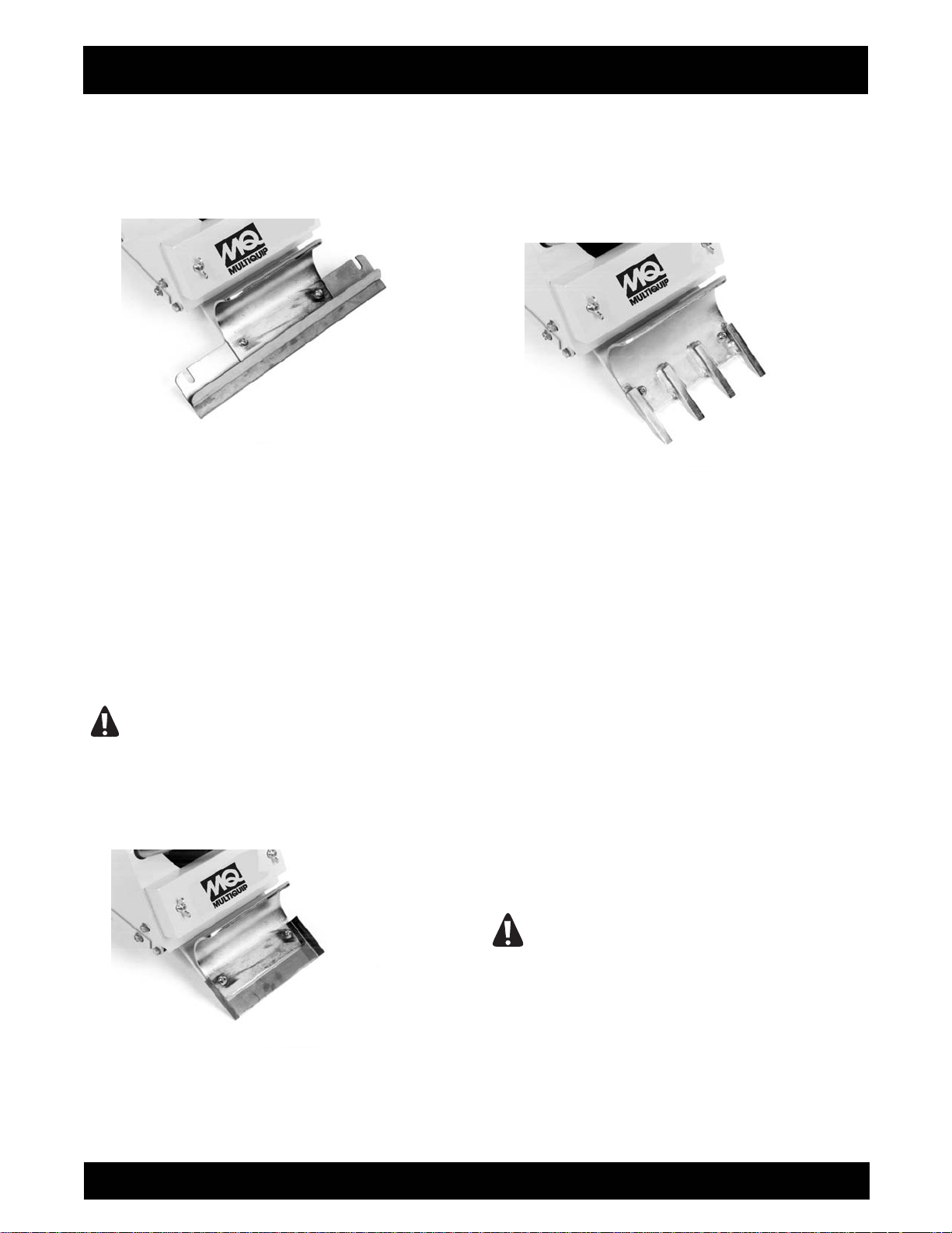
treated for extended service life. Blades a
depict use on either concrete or wood surfaces. When
utilized on concrete, the cutting edge is positioned
facing up. FIGURE 3. On wood flooring surfaces, the
re marked to
like,
SFCS-16 OPERATION AND PARTS MANUAL REV #4 (05/28/09) PAGE 12
Page 13
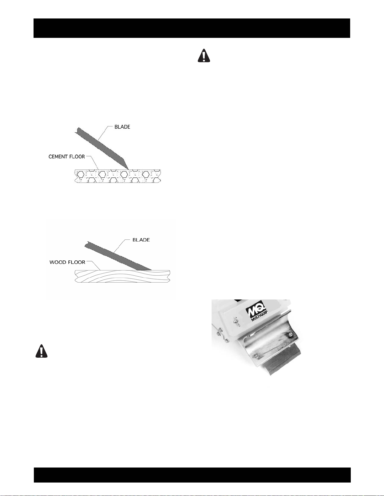
cutting edge faces down against the surface. FIGURE
4. This configuration allows the blade to skim over the
surface and minimize any tendency to gouge or dig
into the wood. A slotted blade configuration is
employed to lower installation and remova l time. The
slotted configuration is also intended to help minimize
direct exposure of hands, arms and other body parts
to the blade during the installation or removal process.
FIGURE 3
FIGURE 4
CAUTION
A protective covering is provided to protect the blade
cutting edge from external damage and minimize the
potential for property damage and/or personal injury.
Store the blade with the protective covering
properly installed to minimize the effects of
external damage to the cutting edge and the
potential for property damage and/or personal
injury.
ASSEMBLY INSTRUCTIONS/OPERATION
DANGER
THE BLADE IS EXTREMELY SHARP. IMPROPER
HANDLING WHILE REMOVING FROM THE
PACKAGE, REMOVING/REINSTALLING THE
PROTECTIVE CUTTING EDGE COVER,
INSTALLING/REMOVING FROM THE MACHINE OR
WHILE IMPROPERLY TRANSPORTING CAN
RESULT IN PROPERTY DAMAGE AND/OR
PERSONAL INJURY.
While individual blade or accessory atta
and configuration may vary, basic operational
characteristics are identical: impact against a floor
surface and remove the covering material. This
common operational characteristic has led to the
development of the following popular blade
configurations and accessory attachments:
Angled Mastic Removal Blade.
This blade configuration is utilized to remove a wide
variety of adhesives, mastics and material residues
from concrete surfaces. The steep angle increases
the cutting edge position relative to the floor surf
The angle increase allows the blade to better
penetrate the material and then shear and scrape it
from the floor surface. The cutting edge faces down
toward the floor surface. Angled mastic blades are
utilized on concrete surfaces only. Use on wood
surfaces will only dig into and remove substrate
material. FIGURE 5.
FIGURE 5
Straight Beveled Cutting Edge Blade.
This blade configuration is utilized to remove a wide
variety of VCT and linoleum tiles along with general
material removal from concrete and wood surfaces.
Some blades feature two cutting edges. Position the
blade edge facing up for use on concrete surfaces.
chment design
ace.
SFCS-16 OPERATION AND PARTS MANUAL REV #4 (05/28/09) PAGE 13
Page 14
ASSEMBLY INSTRUCTIONS/OPERATION
Flip the blade over for use on wood surfaces. Specific
blades are available for removing covering materials
from either concrete or wood surfaces. This blade
design does not allow it to be flipped over for use on
both concrete and wood surfaces. FIGURE 6.
FIGURE 6
Straight Beveled Scoring Blades.
This blade configuration is utilized to remove glued
type carpet and soft sheet type (PVC, rubber,
linoleum, etc) materials from concrete and wood
surfaces. FIGURE 7. The cutting wings score the
covering material to aid in removal. Specific part
numbers are available for removing covering materials
from either concrete or wood surfaces. The blade
design does not allow it to be flipped over for use on
both concrete and wood surfaces.
Use of a straight beveled scoring blade with the
cutting wings positioned down and against the
work surface can result in unrepairable surface
damage and personal injury.
FIGURE 7
CAUTION
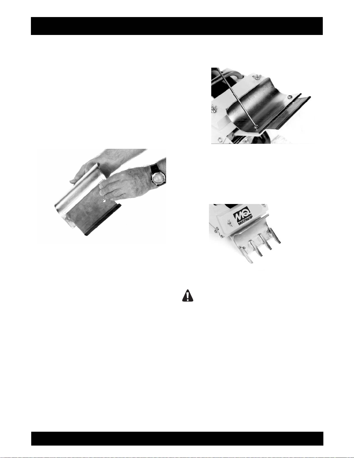
Ceramic Tile Ripper Attachment.
This att
projects requiring the removal of ceramic, thicker VCT
and linoleum tiles, hardwood floors, etc, from concrete
and wood surfaces. FIGURE 8.
FIGURE 8
The primary design function for the FLOOR
COVERING SCRAPER is not to remove ceramic
tile. Removing ceramic tile is a secondary job
application that may require the use of a machine
and/or process with significant greater stability,
power and/or impact force. The FLOOR COVERING
SCRAPER has demonstrated the ability to remove
ceramic tile for those job applications classified as
light to medium duty. An improper job application
for the FLOOR COVERING SCRAPER may result in
property damage and/or personal injury.
INSTALLING A BLADE OR THE CERAMIC TILE
RIPPER ATTACHMENT TO THE FLOOR
COVERING SCRAPER.
Tools required: 1 each, 5/32 inch T handled Allen
wrench provided with the machine.
Parts required: 1 each, blade appropriate for the job
application or the ceramic tile ripper attachment.
WHEN INSTALLING OR REMOVING A BLADE OR
THE CERAMIC TILE RIPPER ATTACHMENT
TO/FROM THE FLOOR COVERING SCRAPER
ALWAYS WEAR THE APPROPRIATE SAFETY
EYEWEAR, GLOVES, LEATHER SHOES AND
LONG PANTS TO MAXIMIZE PERSONAL
PROTECTION FROM THE SHARP EDGE (S).
IMPROPER CONTACT WITH A SHARP EDGE CAN
achment is designed for light to medium duty
DANGER
SFCS-16 OPERATION AND PARTS MANUAL REV #4 (05/28/09) PAGE 14
Page 15
ASSEMBLY INSTRUCTIONS/OPERATION
RESULT IN PROPERTY DAMAGE AND/OR
PERSONAL INJURY.
1) Properly disconnect the extension cord or the
FLOOR COVERING SCRAPER from the power
source.
2) To place the operator handle in the work position,
move the handle upright so that the ball-detent pins
can be inserted through the operator handle and main
frame. Determine the ball-detent pins are inserted
through the operator handle and main frame to fully
expose the ball detent. FIGURE 9.
FIGURE 9
DANGER
THE BALL DETENT MUST BE FULLY EXPOSED
AGAINST THE MAIN FRAME TO PROVIDE THE
PROPER PIN RETAINING FORCE. AN IMPROPER
PIN RETAINING CONFIGURATION CAN RESULT IN
UNEXPECTED OPERATOR HANDLE MOVEMENT.
THIS OCCURRENCE CAN RESULT IN PROPERTY
DAMAGE AND/OR PERSONAL INJURY.
3) Loosen the threaded handle knobs and extend the
operator handle out until the internal handle stops
thrust against the threaded studs. Retighten the
knobs. FIGURE 10.
FIGURE 10
CAUTION
Improper knob tension and/or improperly securing
the operator handle to the main frame can result in
an unstable platform configuration. An unstable
platform configuration can result in property
damage and/or personal injury.
4) Tilt the FLOOR COVERING SCRAPER back until
the operator handle comes in contact with the surface.
The FLOOR COVERING SCRAPER may not be in a
stable position in this configuration. To minimize the
possibility of property damage and/or personal injury,
properly secure an appropriate weight to the handle
for added stability. Other means can also be utilized to
support the frame and provide proper machine
stability. Appropriate wheel chocks are also
recommended. FIGURE 11.
DANGER
EXERCISE EXTREME CAUTION WHEN WORKING
NEAR OR UNDER THE FLOOR COVERING
SCRAPER WITH THE OPERATOR HANDLE TILTED
BACK IN THE SERVICE POSITION. IF THE FLOOR
COVERING SCRAPER IS NOT POSITIONED IN A
STABLE CONFIGURATION, WITH ADEQUATE
COUNTERWEIGHT PROPERLY SECURED,
UNEXPECTED MOVEMENT CAN ALLOW THE
MACHINE TO FALL BACK TO THE WORK
SURFACE. THIS OCCURRENCE CAN RESULT IN
PROPERTY DAMAGE AND/OR PERSONAL
INJURY.
FIGURE 11
SFCS-16 OPERATION AND PARTS MANUAL REV #4 (05/28/09) PAGE 15
Page 16
ASSEMBLY INSTRUCTIONS/OPERATION
5) Wear proper safety apparel and equipment. Use the
T-handled Allen wrench to loosen the button head cap
screws which secure the fence plate to the exciter
plate. This will allow the blade to slide in between the
fence plate and the exciter plate. IT IS NOT
NECESSARY TO REMOVE THE FENCE PLATE
FROM THE EXCITER PLATE. The fence plate has
an integral stop which the edge of the blade thrusts
up against. FIGURE 12. Blades are provided with a
covering that protects the cutting edge. Do not remove
the protective covering until you are ready to operate
the FLOOR COVERING SCRAPER. Exercise extreme
caution when removing and/or reinstalling the
protective cover.
FIGURE 12
6) Two attachment configurations for blades are
utilized. Narrow (less than 6 inches (152 mm) wide)
blades are positioned between the two button head
capscrews a
FIGURE 13. Use the T-handled Allen wrench to
tighten the button head screws. Wider (greater than 6
inches (152 mm) wide) blades incorporate a slotted
design which slides around the button head
capscrews. The slots afford increased clamping
pressure for the wider blades during the covering
removal process. SLOTS ALSO MAKE IT
UNNECESSARY TO REMOVE THE FENCE PLATE
FROM THE EXCITER PLATE. Use the T-handled
Allen wrench to tighten the button head capscrews.
FIGURE 13. If the FLOOR COVERING SCRAPER is
to be utilized immediately, remove the protective cover
from the blade. If the FLOOR COVERING SCRAPER
is not be utilized immediately, do not remove the
protective covering from the blade.
nd thrust up against the fence plate stop.
FIGURE 13
7) The installation of the ceramic tile ripper attachment
is similar to that of a blade with the exception that the
fence plate is removed the exciter plate. The ceramic
tile ripper attachment fa
plate. Follow the same tightening procedure as with a
blade. FIGURE 14.
FIGURE 14
CAUTION
stens directly to the exciter
For all blades and the ceramic tile ripper
attachment, tighten the button head capscrews
with the T-handled Allen wrench provided. Do not
utilize another wrench type and/or configuration.
The T-handled Allen wrench was chosen to place
body parts a practical distance from the blade
during the fastener tightening and loosening
process. Do not apply excessive impact force to
the button head capscrews. Ample seating torque
can be applied by the T-handled Allen wrench and
normal arm strength levels. Excessive impact
force can cause the T- handled Allen wrench to
slip out of the button head capscrew, resulting in
property damage and/or personal injury.
SFCS-16 OPERATION AND PARTS MANUAL REV #4 (05/28/09) PAGE 16
Page 17

ASSEMBLY INSTRUCTIONS/OPERATION
CAUTION
Do not substitute a different fastener type for the
button head capscrew configuration. The button
head configuration was chosen for operational
considerations. The use of another fastener types
can increase the potential for property damage
and/or personal injury.
DANGER
BLADES ARE EXTREMELY SHARP. CONTACT
WITH THE BLADE CAN RESULT IN PROPERTY
DAMAGE AND/OR PERSONAL INJURY. BLADES
ARE PROVIDED WITH A PROTECTIVE COVER
OVER THE CUTTING EDGE. EXERCISE EXTREME
CAUTION WHEN REMOVING AND/OR
REINSTALLING THE PROTECTIVE COVER. STORE
THE BLADE WITH THE PROTECTIVE COVER
PROPERLY INSTALLED TO MINIMIZE THE
POTENTIAL FOR BLADE DAMAGE AND/OR
PERSONAL INJURY.
8) Return the FLOOR COVERING SCRAPER to its
normal operating position.
9) Determine that the ON/OFF switch located on the
operator handle is in the OFF position. If the FLOOR
COVERING SCRAPER is to be used immediately,
then reconnect the extension cord or FLOOR
COVERING SCRAPER to the power source.
DANGER
UNEXPECTED MACHINE START UP CAN RESULT
IN PROPERTY DAMAGE AND/OR PERSONAL
INJURY.
REMOVING THE BLADE OR CERAMIC TILE
RIPPER ATTACHMENT FROM THE FLOOR
COVERING SCRAPER.
Tools Required: 1 each, 5/32 inch T-handled Allen
wrench provided with the machine.
DANGER
WHEN INSTALLING OR REMOVING A BLADE OR
THE CERAMIC TILE RIPPER ATTACHMENT
TO/FROM THE FLOOR COVERING SCRAPER,
ALWAYS WEAR THE APPROPRIATE SAFETY
EYEWEAR, GLOVES, LEATHER SHOES AND
LONG PANTS TO MAXIMIZE PERSONAL
PROTECTION FROM THE SHARP EDGE(S).
IMPROPER CONTACT WITH A SHARP EDGE CAN
RESULT IN PROPERTY DAMAGE AND/OR
PERSONAL INJURY.
1) Properly disconnect the extension cord or the
FLOOR COVERING SCRAPER from the power
source.
2) To place the operator handle in the work position,
move the handle upright so that the ball-detent pins
can be inserted through the operator handle and main
frame. Determine the ball-detent pins are inserted
through the operator handle and main frame to fully
expose the ball detent. FIGURE 15
FIGURE 15
THE BALL DETENT MUST BE FULLY EXPOSED
AGAINST THE MAIN FRAME TO PROVIDE THE
PROPER PIN RETAINING FORCE. AN IMPROPER
PIN RETAINING CONFIGURATION CAN RESULT IN
UNEXPECTED OPERATOR HANDLE MOVEMENT.
THIS OCCURRENCE CAN RESULT IN PROPERTY
DAMAGE AND/OR PERSONAL INJURY.
3) Loosen the threaded handle knobs and extend the
operator handle out until the internal handle stops
thrust against the treaded studs. Retighten the knobs.
FIGURE 16.
DANGER
SFCS-16 OPERATION AND PARTS MANUAL REV #4 (05/28/09) PAGE 17
Page 18

ASSEMBLY INSTRUCTIONS/OPERATION
CAUTION
Improper knob tension and/or improperly securing
the operator handle to the main frame can result in
an unstable platform configuration. An unstable
platform configuration can result in property
damage and/or personal injury.
FIGURE 16
4) Tilt the FLOOR COVERING SCRAPER back until
the operator handle comes in contact with the surface.
The FLOOR COVERING SCRAPER may not be in a
stable position in this configuration. To minimize the
possibility of property damage and/or personal injury,
properly secure an appropriate weight to the handle
for added stability. Other means can also be utilized to
support the frame and provide proper machine
stability. Appropriate wheel chocks are also
recommended. FIGURE 17.
FIGURE 17
DANGER
EXERCISE EXTREME CAUTION WHEN WORKING
NEAR OR UNDER THE FLOOR COVERING
SCRAPER WITH THE OPERATOR HANDLE TILTED
BACK IN THE SERVICE POSITION. IF THE FLOOR
COVERING SCRAPER IS NOT POSITIONED IN A
STABLE CONFIGURATION, WITH ADEQUATE
COUNTERWEIGHT PROPERLY SECURED,
UNEXPECTED MOVEMENT CAN ALLOW THE
MACHINE TO FALL BACK TO THE WORK
SURFACE. THE RESULT CAN BE PROPERTY
DAMAGE AND/OR PERSONAL INJURY.
5) Reinstall the protective blade cover. Exercise
extreme caution when removing and/or reinstalling the
protective cover. Use the T-handled Allen wrench to
loosen the button head capscrews which secure the
blade between the fence plate and exciter plate.
Remove the blade and store in an appropriate
location. Use the T-handled Allen wrench to tighten
the button head capscrews. Keep the button head
capscrews tight to minimize becoming lost.
6) The removal of the ceramic tile ripper attachment is
similar to that of a blade with the exception that the
fence plate is reinstalled to the exciter plate. Follow
the same tightening procedure as with a blade.
CAUTION
For all blades and the ceramic tile ripper
attachment, tighten the button head capscrews
only with the T-handled Allen wrench provided. Do
not utilize another wrench type and/or
configuration. The T-handled Allen wrench was
chosen to place body parts a practical distance
from the blade during the fastener tightening and
loosening process. Do not apply excessive impact
force to the button head cap screws. Ample
seating torque can be applied by the T-handled
Allen wrench. Excessive impact force can cause
the T- handled Allen wrench to slip out of the
button head capscrew, resulting in property
damage and/or personal injury.
CAUTION
Do not substitute a different fastener type for the
button head capscrew configuration. The button
head configuration was chosen for operational
considerations. The use of other fastener types
can increase the potential for property damage
and/or personal injury.
SFCS-16 OPERATION AND PARTS MANUAL REV #4 (05/28/09) PAGE 18
Page 19

DANGER
ASSEMBLY INSTRUCTIONS/OPERATION
BLADES ARE EXTREMELY SHARP. CONTACT
WITH THE BLADE CAN RESULT IN PROPERTY
DAMAGE AND/OR PERSONAL INJURY. BLADES
ARE PROVIDED WITH A PROTECTIVE COVER
OVER THE CUTTING EDGE. EXERCISE EXTREME
CAUTION WHEN REMOVING AND/OR
REINSTALLING THE PROTECTIVE COVER. STORE
THE BLADE WITH THE PROTECTIVE COVER
PROPERLY INSTALLED TO MINIMIZE THE
POTENTIAL FOR BLADE DAMAGE AND/OR
PERSONAL INJURY.
7) Return the FLOOR COVERING SCRAPER to its
normal operating position.
8) Determine that the ON/OFF switch located on the
operator handle is in the OFF position. IF the FLOOR
COVERING SCRAPER is to be used immediately,
then reconnect the extension cord or FLOOR
COVERING SCRAPER to the power source.
DANGER
UNEXPECTED MACHINE START UP CAN RESULT
IN PROPERTY DAMAGE AND/OR PERSONAL
INJURY.
Operation
OPERATIONAL DISCLAIMER.
THE MANUFACTURER OF THE FLOOR COVERING
SCRAPER MAKES NO WARRANTY OR
GUARANTEE THAT IT IS MERCHANTABLE
AND/OR SUITABLE FOR ANY SPECIFIC JOB
APPLICATION AND THAT IT WILL HAVE THE
CAPABILITY AND POWER REQUIRED TO
REMOVE ANY SPECIFIC COVERING FROM ANY
SPECIFIC WORK SURFACE.
CALIFORNIA PROPOSITION 65 DISCLAIMER.
DANGER
THE DUSTS/BYPRODUCTS FROM THE COVERING
REMOVAL PROCESS ASSOCIATED WITH THE
OPERATION OF THE FLOOR COVERING
SCRAPER CAN CONTAIN CHEMICALS KNOWN TO
CAUSE CANCER, BIRTH DEFECTS, OR OTHER
REPRODUCTIVE HARM.
INFORMATION RELATIVE TO MINIMUM
COMPONENT STANDARDS FOR THE OPERATION
OF THE FLOOR COVERING SCRAPER.
For operational safety and overall productivity
considerations, it is required that specific FLOOR
COVERING SCRAPER components meet minimum
acceptable operational standards BEFORE utilization:
1) Operator handle be properly mounted to the main
frame, with factory supplied ball-detent type retaining
pins that properly secure the handle to the main frame
while in the work position.
2) The operator handle is equipped with properly fitting
handle grips of sufficient integrity to allow for proper
job function as outlined within this manual. Loose
fitting handle grips or grips without full end caps are
not permitted.
3) An ON/OFF motor switch that allows it to perform its
intended job function as outlined within this manual.
Replace a
factory approved replacement part only.
4) An extension cord and GFI that allows this
accessory to perform its intended job function as
outlined within this manual. Replace any damaged
extension cord or GFI with a factory approved
replacement part only.
5) Exciter plate elastomeric rubber mounts which allow
them to perform their intended job function as outlined
within this manual. Do not operate the FLOOR
COVERING SCRAPER without the correct number of
exciter plate elastomeric rubber mounts. Do not
operate the FLOOR COVERING SCRAPER with a
damaged and/or improperly secured rubber mount.
Replace any damaged rubber mount with a factory
approved repl
6) Blade(s) and/or ceramic tile ripper attachment of
proper structural integrity (void of cracks, etc),
straightness, sharpness, etc which are retained by the
proper fasteners. Replace worn or damaged blades,
fasteners and the ceramic tile ripper attachment with a
factory approved replacement part only.
7) All safety decals, Operator Manual and operational
information decals (including the applicable Quik Tips
information) must be in proper and readable condition.
Replace a
Operator Manual and/or information decal with a
factory approved replacement part only.
ny damaged ON/OFF motor switch with a
acement part only.
ny missing or damaged safety decal,
SFCS-16 OPERATION AND PARTS MANUAL REV #4 (05/28/09) PAGE 19
Page 20

ASSEMBLY INSTRUCTIONS/OPERATION
TRANSPORTING THE FLOOR COVERING
SCRAPER.
The FLOOR COVERING SCRAPER has an
operational weight that prohibits one person from
loading and/or unloading it alone by conventional,
physical efforts.
DANGER
DO NOT ATTEMPT TO LIFT THE FLOOR
COVERING SCRAPER UP INTO A
TRANSPORTATION VEHICLE WITH THE USE OF
ONE PERSON ALONE. DO NOT ATTEMPT TO
LOWER THE FLOOR COVERING SCRAPER FROM
A TRANSPORTATION VEHICLE WITH THE USE OF
ONE PERSON ALONE. LIFT AND/OR LOWER THE
FLOOR COVERING SCRAPER ONLY BY THE USE
OF A POWER TAILGATE UNIT, A SUITABLE HOIST
UNIT OF PROPER CAPACITY AND/OR
CONFIGURATION OR BY THE USE OF A PROPER
QUANTITY OF PERSONNEL IN PROPER
PHYSICAL/MENTAL CONDITION.
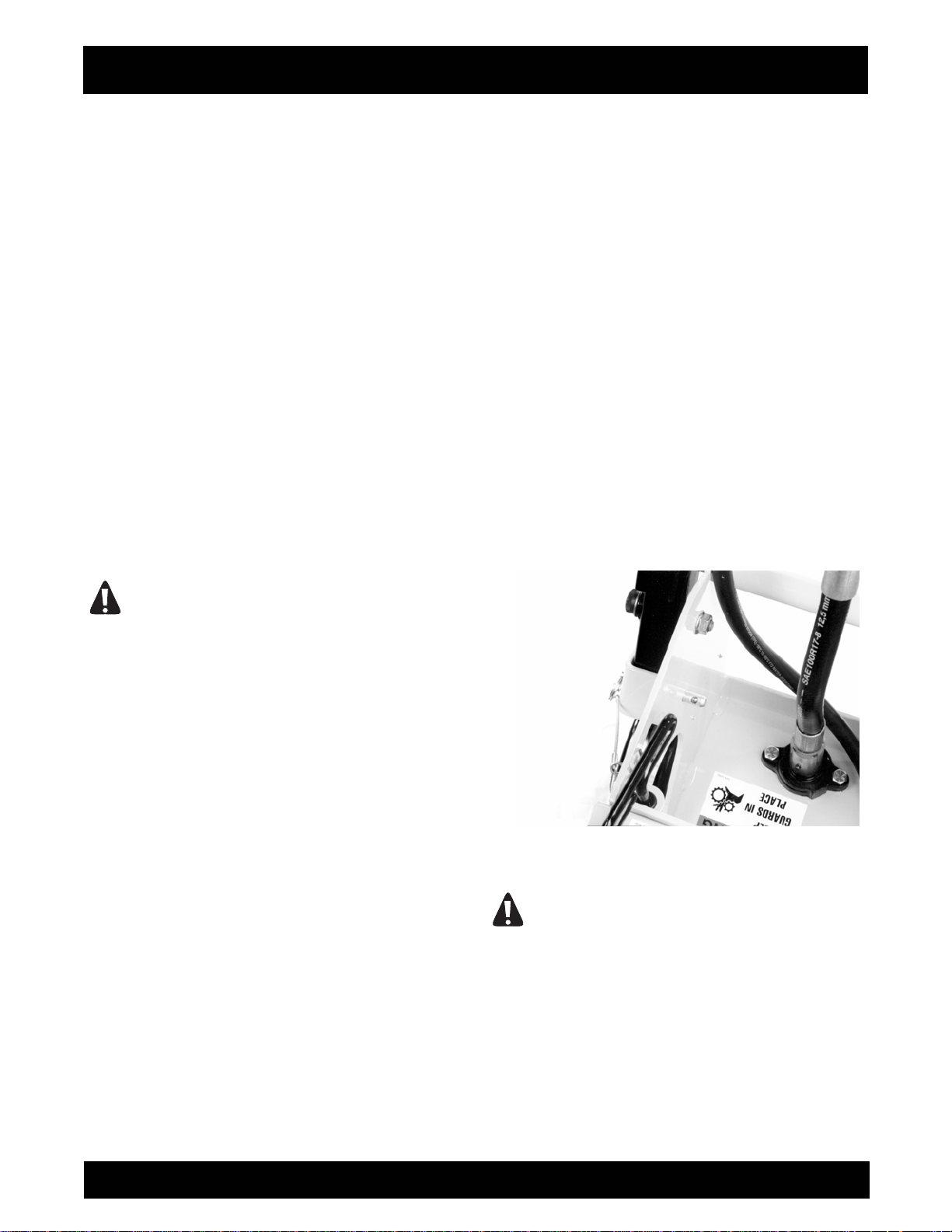
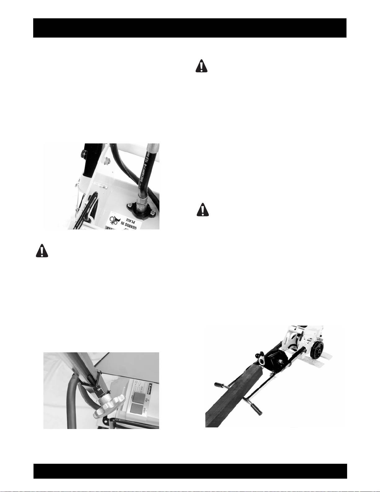
1) The FLOOR COVERING SCRAPER can be hoisted
by a mechanical device incorporating a chain and
suitable attachment device to the lifting bail area
located behind the electric motor. FIGURE 18. This
location may not always locate the exact position of
the center of gravity for the FLOOR COVERING
SCRAPER. Lifting handles are also provided on both
sides of the main frame. These handles can be
utilized by personnel whenever lifting/lowering the
FLOOR COVERING SCRAPER. FIGURE 19.
FIGURE 18
DANGER
EXERCISE EXTREME CAUTION WHEN UTILIZING
A MECHANICAL DEVICE FOR LIFTING THE
FLOOR COVERING SCRAPER. UTILIZE THE
MECHANICAL DEVICE IN ACCORDANCE TO
BOTH ITS DESIGNED STATIC AND DYNAMIC
LOADING ENVELOPES. DO NOT UTILIZE THE
MECHANICAL DEVICE UNTIL THIS INFORMATION
IS PROPERLY KNOWN AND UNDERSTOOD BY
ALL APPLICABLE PERSONNEL. FAILURE TO
PROPERLY UTILIZE THE MECHANICAL DEVICE
CAN RESULT IN PROPERTY DAMAGE AND/OR
PERSONAL INJURY.
CAUTION
Do not drop the FLOOR COVERING SCRAPER
directly upon the exciter plate. Direct impact
against the exciter plate can result in damage to
components including the plate, elastomeric
rubber mounts, electric motor shaft, bearings, etc.
FIGURE 19
2) To minimize the possibility of damage to the
FLOOR COVERING SCRAPER, always transport in
its normal, upright position. All equipment must be
secured in/on vehicles with suitable strapping or tiedowns. Personnel should not be transported in the
same compartment as equipment. Consult applicable
OSHA and transportation regulations (local, State and
Federal) for the proper transportation of the FLOOR
COVERING SCRAPER.
3) Do not transport the FLOOR COVERING
SCRAPER with a blade or the ceramic tile ripper
attachment attached to the main frame in the following
configurations:
a) To and from the jobsite.
b) For longer distances while being repositioned on
the jobsite.
c) When traversing up and down stairways.
d) While performing m
e) Lifting up/into or/down from a transporting vehicle.
aintenance and/or repairs.
SFCS-16 OPERATION AND PARTS MANUAL REV #4 (05/28/09) PAGE 20
Page 21

ASSEMBLY INSTRUCTIONS/OPERATION
Remove the blade or ceramic tile ripper attachment
according to the procedures as outlined in this manual
for the above listed configurations.
DANGER
LIFTING, LOWERING AND TRANSPORTING THE
FLOOR COVERING SCRAPER WITH A BLADE OR
CERAMIC TILE RIPPER ATTACHMENT INSTALLED
CAN RESULT IN PROPERTY DAMAGE AND/OR
PERSONAL INJURY.
4) When transporting to and from the jobsite, block the
bottom of the main frame to prevent direct impact
blows against the exciter plate. This procedure will
reduce impact loads directly to the elastomeric rubber
mounts, minimize their deflection and increase service
life.
ADJUSTING THE OPERATOR HANDLE HEIGHT.
The FLOOR COVERING SCRAPER incorporates a
handle that can be adjusted to compensate for
variances in operator height. Handle height can be
infinitely varied between the stop limits. No external
tools are required. Correct handle height can increase
overall machine productivity and reduce operator
fatigue.
1) Loosen the handle knobs located at the rear of the
ndle. Extend the knobs out approximately 1/2 inch
ha
(13 mm). FIGURE 20.
FIGURE 20
2) Position the operator handle grips at a height
convenient to the specific operator. In most
configurations, the operator handle grips will be at
approximately belt height.
3) Tighten the handle knobs finger tight. Determine the
adjustable section of the operator handle is properly
secured tight against the fixed section.
CAUTION
Improper knob tension and/or improperly securing
the operator handle to the main frame can result in
an unstable platform configuration. An unstable
platform configuration can result in property
damage and/or personal injury.
DANGER
DETERMINE THE THREADED STUDS ARE
PROPERLY SEATED AGAINST THE SLIDING
SECTION OF THE OPERATOR HANDLE. THE
ADJUSTABLE SECTION MUST BE FIRMLY
SECURED TIGHT AGAINST THE FIXED SECTION
OF THE OPERATOR HANDLE. IMPROPERLY
SECURED STUDS CAN RESULT IN INADVERTENT
OPERATOR HANDLE MOVEMENT AND/OR
SEPARATION, RESULTING IN PROPERTY
DAMAGE AND/OR PERSONAL INJURY
STARTING THE FLOOR COVERING SCRAPER ON
THE JOBSITE.
1) Position the FLOOR COVERING SCRAPER on a
flat and level surface of firm foundation.
2) Install a blade or the ceramic tile ripper attachment
per the procedures as outlined in this manual.
3) Determine that the ON/OFF switch located on the
operator handle is in the OFF position.
DANGER
UNEXPECTED MACHINE START UP CAN RESULT
IN PROPERTY DAMAGE AND/OR PERSONAL
INJURY.
4) The FLOOR COVERING SCRAPER is designed to
operate from a clean, 15 ampere, 115 VAC, 60 Hz,
nominal power source. A clean power source refers to
the amperage available from the individual electrical
circuit selected. Additional electrical products already
utilizing the same circuit will reduce the available
amperage, and can result in starting and operational
difficulties.
SFCS-16 OPERATION AND PARTS MANUAL REV #4 (05/28/09) PAGE 21
Page 22

CAUTION
Operating the Surface Grinder from a power
source of improper voltage and/or amperage will
result in unrepairable damage to the electric motor
and related controls.
5) Providing proper voltage and amperage levels to
the electric motor is essential to obtain maximum
productivity and service life. Low voltage and
amperage levels will cause the motor to overheat. The
motor is equipped with automatic thermal protection
device that will stop it before major internal damage
can result. After the motor has cooled to an acceptable
temperature level, the switch must be manually
activated to restart. FIGURE 21.
FIGURE 21
6) The FLOOR COVERING SCRAPER utilizes a
factory supplied extension cord equipped with an
integral GFI device. The GFI device is intended to
protect both the operator and electric motor in the
event a ground fault is developed during operation.
The extension cord is 37 foot (11 m) long, fabric
from 12 AWG wire and incorporates a NEMA 5-15P
plug and a NEMA L5-15R twist lock type receptacle.
The twist clock feature allows the extension cord to be
pulled by the FLOOR COVERING SCRAPER without
becoming disconnected.
DANGER
BEFORE USE, PROPERLY INSPECT THE
EXTENSION CORD AND WIRING DEVICES FOR
STRUCTURAL INTEGRITY. DO NOT UTILIZE A
CORD WITH A WORN OR CUT OUTER JACKET
MATERIAL. DO NOT UTILIZE A CORD WITH
EXPOSED INNER WIRES OR INSULATION
ASSEMBLY INSTRUCTIONS/OPERATION
ated
MATERIAL. DO NOT UTILIZE A CORD THAT HAS
BEEN REPAIRED WITH ELECTRICAL TAPE. DO
NOT UTILIZE A CORD WITH A CRACKED AND/OR
DAMAGED GFI CASE. USE OF AN EXTENSION
CORD OF IMPROPER STRUCTURAL INTEGRITY
AND/OR DAMAGED GFI CAN RESULT IN
PROPERTY DAMAGE AND/OR PERSONAL
INJURY.
DANGER
ALL ELECTRICAL WIRING, INCLUDING
EXTENSION CORD GAUGE SIZE AND/OR
LENGTH, MUST BE INSTALLED AND/OR
APPROVED IN ACCORDANCE TO LOCAL
ELECTRICAL CODES AND PRACTICES. AN
IMPROPER WIRING INSTALLATION CAN RESULT
IN PROPERTY DAMAGE AND/OR PERSONAL
INJURY.
7) Determine that the power source receptacle to be
utilized is properly grounded. This can be
accomplished with proper testing equipment and
procedures. If there are any questions regarding the
suitability of a specific power receptacle, contact your
dealer or our Customer Service Department for
assistance BEFORE utilizing the FLOOR COVERING
SCRAPER. There is no charge for this service. A
qualified electrician may need to be consulted.
8) If additional extension cord length is required for a
specific job application, an additional extension cord
can be utilized in conjunction with an external GFI.
Plug the receptacle of the additional extension cord
into the factory supplied GFI. Plug the ground fault
circuit interrupter into the power source receptacle.
Connect the extension cord plug into the external GFI.
This configuration will allow any fault over the length of
a defective extension cord to be indicated. Extension
cord gauge size and length must conform to National
Electric Code standards.
DANGER
FOR MAXIMUM PROTECTION AGAINST A FAULT,
ALWAYS CONFIGURE A GROUND FAULT CIRCUIT
INTERRUPTER TO BE PLUGGED INTO THE
POWER SOURCE RECEPTACLE. A
CONFIGURATION WITH THE GROUND FAULT
CIRCUIT INTERRUPTER PLACED BETWEEN THE
FLOOR COVERING SCRAPER AND THE POWER
SOURCE RECEPTACLE WILL NOT AFFORD
MAXIMUM PROTECTION AGAINST A POTENTIAL
FAULT.
SFCS-16 OPERATION AND PARTS MANUAL REV #4 (05/28/09) PAGE 22
Page 23

ASSEMBLY INSTRUCTIONS/OPERATION
9) Couple the NEMA L5-15R receptacle of the factory
supplied extension cord and the NEMA L5-15P plug
located on the FLOOR COVERING SCRAPER
together. Twist to lock. FIGURE 22. Connect the GFI
to the power source receptacle.
10) Grasp the operator handle with firm gripping.
When starting the electric motor, apply a down force
directly to the operator handle to help reduce
amount of static machine weight against the work
surface. The blade or ceramic tile ripper attachment
should remain in contact with the surface. Turn the
ON/OFF switch to the ON position. Reduce the
amount of applied down force on the operator handle
as the electric motor attains its operational speed.
FIGURE 22
11) The FLOOR COVERING SCRAPER is not
equipped with a centrifugal clutch assembly. The
electric motor is directly coupled to the exciter plate.
The exciter plate will begin to move when the electric
motor starts.
DANGER
the
AS SOON AS THE ELECTRIC MOTOR HAS
STARTED, THE OPERATOR MUST BE IN A
POSITION TO ASSUME DIRECT AND FULL
CONTROL OF THE FLOOR COVERING SCRAPER.
FAILURE TO ASSUME DIRECT AND FULL
CONTROL CAN RESULT IN PROPERTY DAMAGE
AND/OR PERSONAL INJURY.
12) The FLOOR COVERING SCRAPER is stopped by
moving the ON/OFF switch located on the operator
handle to the OFF position. For safety considerations,
it is also recommended that the extension cord be
disconnected from both the FLOOR COVERING
SCRAPER and power source receptacle whenever
the FLOOR COVERING SCRAPER is not in use on
the job site.
DANGER
IF THE FLOOR COVERING SCRAPER IS
EQUIPPED WITH A TOGGLE TYPE ON/OFF
SWITCH THE MOTOR CAN RESTART IF THE
ON/OFF SWITCH IS NOT MOVED TO THE OFF
POSITION WHEN THE POWER SOURCE LOOSES
POWER AND THEN BECOMES RE-ENERGIZED.
13) If the FLOOR COVERING SCRAPER is equipped
with a magnetic start (push button) type ON/OFF
switch, the motor will not restart if the power source
looses power and then becomes re-energized unless
the OFF button is first pushed.
CAUTION
If the FLOOR COVERING SCRAPER and/or an
individual component/accessory does not appear
to be functioning properly, STOP and do not
further operate the FLOOR COVERING SCRAPER
until the proper corrective action has been
completed. If there are any questions regarding
the proper operation of the FLOOR COVERING
SCRAPER, contact the Customer Service
Department BEFORE further utilization. There is
no charge for this service.
OPERATING THE FLOOR COVERING SCRAPER
ON THE JOBSITE.
DANGER
THE COVERINGS REMOVAL PROCESS CAN
PRODUCE EXCESSIVE NOISE, VIBRATION AND
FLYING DEBRIS. ALL OPERATORS AND WORK
PERSONNEL IN THE VICINITY OF THE FLOOR
COVERING SCRAPER MUST WEAR
APPROPRIATE SAFETY EYE WEAR AND
HEARING PROTECTION DEVICES. OTHER
SAFETY APPAREL AND/OR PROCEDURES,
DEEMED NECESSARY BY SUPERVISORY
PERSONNEL MUST ALSO BE WORN AND/OR
PRACTICED BY ALL APPROPRIATE
PERSONNEL.
SFCS-16 OPERATION AND PARTS MANUAL REV #4 (05/28/09) PAGE 23
Page 24

ASSEMBLY INSTRUCTIONS/OPERATION
1) The FLOOR COVERING SCRAPER utilizes an
offset weight design (termed the exciter) that
moves the blade or ceramic tile ripper attachment
with a random orbit oscillation. This design
configuration substantially enhances machine
control and reduces fatigue as long as the blade
or ceramic tile ripper attachment does not come in
direct contact with a protruding obstruction from
the floor. Direct contact with such an obstruction
can result in rapid and jerky directional movement
of the machine. This occurrence can lead to loss
of machine control, property damage and/or
personal injury. In most operating situations, direct
contact with a protruding obstruction from the work
ace will, at a minimum, result in damage to the
surf
blade and/or ceramic tile ripper attachment.
DANGER
EXERCISE EXTREME CAUTION WHEN
OPERATING THE FLOOR COVERING SCRAPER IN
THE VICINITY OF ANCHOR BOLTS, PIPES,
COLUMNS, OPENINGS, PROTRUDING NAIL
HEADS, LARGE CRACKS, UTILITY OUTLETS OR
ANY OBJECT PROTRUDING FROM THE WORK
SURFACE. CONTACT WITH SUCH OBJECTS CAN
LEAD TO LOSS OF MACHINE CONTROL,
RESULTING IN PROPERTY DAMAGE AND/OR
PERSONAL INJURY.
DANGER
ALWAYS MAINTAIN PROPER CONTROL OF THE
FLOOR COVERING SCRAPER. IF AN OPERATOR
LOOSES CONTROL OF THE MACHINE, A
"RUNAWAY" FLOOR COVERING SCRAPER CAN
RESULT IN PROPERTY DAMAGE AND/OR
PERSONAL INJURY. BECAUSE OF THE UNIQUE
OPERATING CHARACTERISTICS OF THE FLOOR
COVERING SCRAPER, THERE IS NO PROVISION
FOR THE ELECTRIC MOTOR TO AUTOMATICALLY
STOP IF THE OPERATOR FAILS TO MAINTAIN
PROPER CONTROL.
PERSONAL INJURY. WHEN WALKING
BACKWARDS DURING THE COVERING REMOVAL
PROCESS, BE AWARE OF DROP OFFS AND
OBSTRUCTIONS.
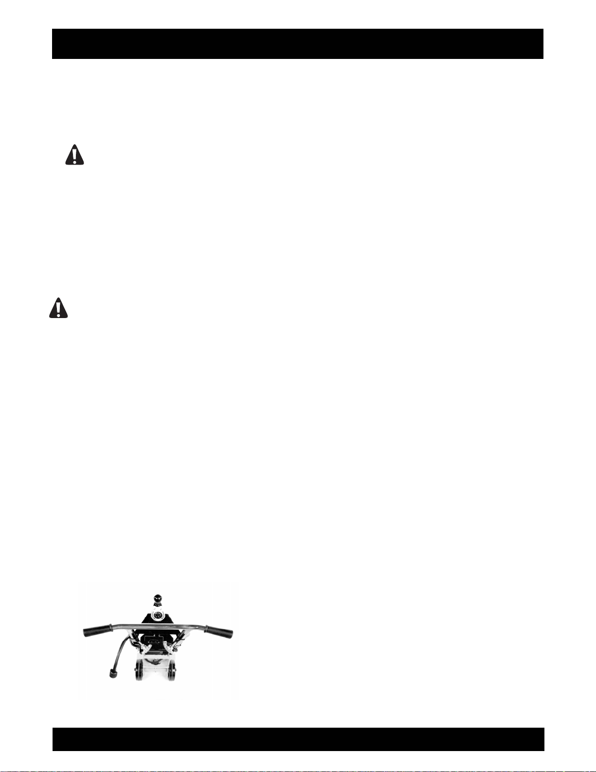
2) Productivity rates with the various blade and/or
attachments can be increased with the addition of
external weight being applied to the front of the
machine. FIGURE 23. Each external weight block
weighs 14 lbs (6.3 kg). Maximum allowable external
weight permits the use of three blocks or 42 lbs (19
kg). Exceeding this figure can result in permanent
structural damage to the FLOOR COVERING
SCRAPER. The additional external weight blocks can
be secured to the machine with the use of longer
length carriage bolts. FIGURE 24.
FIGURE 23
FIGURE 24
DANGER
WHEN OPERATING THE FLOOR COVERING
SCRAPER ON ABOVE GROUND FLOOR LEVELS,
EXERCISE EXTREME CAUTION TO PREVENT
LOSS OF CONTROL THAT COULD ALLOW THE
MACHINE AND/OR OPERATOR TO FALL DOWN
TO LOWER LEVELS. SUCH AN OCCURRENCE
CAN RESULT IN PROPERTY DAMAGE AND/OR
SFCS-16 OPERATION AND PARTS MANUAL REV #4 (05/28/09) PAGE 24
DANGER
DO NOT OPERATE THE FLOOR COVERING
SCRAPER WITHOUT ALL EXTERNAL WEIGHT
PROPERLY SECURED TO THE MAIN FRAME. A
SUDDEN CHANGE IN MOVEMENT OR DIRECTION
CAN ALLOW THE UNSECURED WEIGHT TO FALL
OFF THE FLOOR COVERING SCRAPER,
RESULTING IN LOSS OF MACHINE CONTROL,
Page 25

ASSEMBLY INSTRUCTIONS/OPERATION
PROPERTY DAMAGE AND/OR PERSONAL
INJURY. THIS PROCEDURE IS ESPECIALLY
IMPORTANT WHEN OPERATING THE FLOOR
COVERING SCRAPER ON FLOORS AND/OR
SURFACES ABOVE GROUND LEVEL.
3) Proper operator posture and stance will enhance
productivity rates and minimize fatigue. Adjust the
operator handle height to place the handle grips at
approximately waist level. Keep the upper body as
vertical as possible. This procedure will help to
maximize leverage and minimize back related stress.
Keep feet a comfortable distance apart to help provide
stability and locomotion force. A proper operator
position is depicted in FIGURE 25. Improper operator
positions are depicted in FIGURES 26 and 27. The
proper and improper operator positions depicted in this
manual are not all inclusive.
FIGURE 25
FIGURE 26
FIGURE 27
4) The wide variety of potential covering ma
along with the corresponding variety of jobsite
environments, makes it impossible to develop a
standardized operating procedure for the FLOOR
COVERING SCRAPER. Use of the FLOOR
COVERING SCRAPER will require constant trial a nd
error testing until satisfactory results are achieved.
Experience, gained over time, along with good
common sense will help minimize the amount of
necessary testing. Many factors will directly affect the
operating parameters and/or techniques utilized for a
specialized job application. Some of these factors
include:
a) Work surface material yield and tensile values. As a
general rule, these values will determine material
removal rate per unit of time. Ma
and tensile values will characteristically resist/limit
penetration. For such materials, the accepted
procedure is to decrease blade width and determine
optimum blade angle relative to the floor surface. This
will require increasing or decreasing the blade angle
with the Back Saver™ Blade Control System. Other
added benefits to this technique are decreased
vibration, less operator fatigue and increased
component service life.
b) Higher material removal rates can sometimes be
achieved by making a series of passes 90 degrees to
each other to form a waffle like pattern. This technique
is especia
accumulations of rubber type materials, material
residues and dirt debris from industrial floors.
lly useful when removing deeper
terials with high yield
terials
SFCS-16 OPERATION AND PARTS MANUAL REV #4 (05/28/09) PAGE 25
Page 26

ASSEMBLY INSTRUCTIONS/OPERATION
c) The covering removal process can be extremely
abrasive to the blade cutting edge. Blades can be
sharpened in the field by the use of the metal file
stored on the fixed section of the operator handle. Use
of the file in the field will not duplicate the original
blade manufacturing process, but can significantly
increase overall productivity rates versus the
continued use of a dull blade. Remove the blade from
the FLOOR COVERING SCRAPER per the
procedures outlined in this manual. Clamp the blade
in a suitable vice. Use the file to sharpen the blade
with a procedure similar to that of sharpening a rotary
lawnmower blade. FIGURE 28.
FIGURE 28
DANGER
EXERCISE EXTREME CAUTION WHEN
SHARPENING THE BLADE. CLAMP THE BLADE
FIRMLY IN THE VICE. REMAIN CLEAR OF THE
CUTTING EDGE DURING THE SHARPENING
PROCESS. IMPROPER CONTACT WITH THE
BLADE CAN RESULT IN PROPERTY DAMAGE
AND/OR PERSONAL INJURY.
5) The coverings removal process on many work
surface materials can produce sparks, dust and other
foreign particle contamination. Many covering
materials, adhesives and/or mastics can contain
asbestos and other chemicals that are known to cause
physical harm and/or affect the environment. These
types of materials need to be properly identified,
contained and disposed of according to established
OSHA, EPA and other rules and regulations.
DANGER
SPARKS PRODUCED BY THE ACTIONS OF
BLADE AND/OR CERAMIC TILE RIPPER
ATTACHMENT AGAINST THE WORK SURFACE
(FOR EXAMPLE: STRIKING ANCHOR BOLTS) CAN
RESULT IN A FIRE AND/OR EXPLOSION. THIS
OCCURRENCE CAN RESULT IN PROPERTY
DAMAGE AND/OR PERSONAL INJURY.
DANGER
THE CREATION OF DUST AND OTHER FOREIGN
PARTICLE CONTAMINATION FROM THE
COVERING REMOVAL PROCESS CAN RESULT IN
PROPERTY DAMAGE AND/OR PERSONAL
INJURY. FOR SUCH OPERATING CONDITIONS,
ALWAYS WEAR A NIOSH/MSHA APPROVED
DUST/MIST RESPIRATOR AND APPROPRIATE
SAFETY RELATED APPAREL. CONSULT
APPLICABLE OSHA REGULATIONS FOR
SPECIFIC INFORMATION.
6) Dust and other particle contamination can be
controlled by the use an appropriate industrial type
vacuum system to remove/control dust and other
particle contamination from the work surface.
DANGER
ALWAYS UTILIZE A VACUUM SYSTEM TO
OPERATE WITHIN THE SPECIFIC JOBSITE
REQUIREMENT. DUST MATERIAL CAN MEET
CLASS II OR CLASS III SPECIFICATIONS OF THE
NATIONAL ELECTRIC CODE® FOR HAZARDOUS
LOCATION CLASSIFICATIONS. CONSIDERATION
MUST ALSO BE GIVEN TO THE CREATION OF
HAZARDOUS TYPE MATERIALS REQUIRING
SPECIFIC DISPOSAL PROCEDURES. DETERMINE
THAT THE VACUUM SYSTEM IS PROPERLY
DESIGNED TO OPERATE WITHIN THESE
ATMOSPHERES. CONSULT CURRENT NATIONAL
ELECTRIC CODE®, OSHA AND ENVIRONMENTAL
PROTECTION AGENCY REGULATIONS FOR
SPECIFIC INFORMATION.
7) Water applied to the work surface is not normally
utilized to control dust and other particle
contamination. Water, and/or other conductive
materials, should be removed from the work surface
by an industry approved and/or accepted practice
BEFORE utilizing the FLOOR COVERING SCRAPER
to remove the covering material. The presence of
water and/or any other conductive material on the
work surface can substantially increase the potential
SFCS-16 OPERATION AND PARTS MANUAL REV #4 (05/28/09) PAGE 26
Page 27

ASSEMBLY INSTRUCTIONS/OPERATION
electrocution concern for the operator and/or
associated work personnel.
DANGER
WATER OR OTHER CONDUCTIVE MATERIALS
DEPOSITED ON THE WORK SURFACE
INCREASES THE ELECTROCUTION POTENTIAL
FOR THE OPERATOR AND/OR ASSOCIATED
WORK PERSONNEL. DETERMINE THE FLOOR
COVERING SCRAPER IS PROPERLY GROUNDED
(NO FAULTS), THE EXTENSION CORD IS FREE OF
CUTS, ABRASIONS, EXPOSED CABLE STRANDS
AND THAT THE GFI PROPERLY FUNCTIONS TO
ELIMINATE FAULT CONCERNS. IMPROPER
MACHINE GROUNDING, EXTENSION CORDS
AND/OR GFI CAN RESULT IN PROPERTY
DAMAGE AND/OR PERSONAL INJURY.
8) Normal usage of the FLOOR COVERING
SCRAPER will allow the build-up and accumulation of
work surface materials on the surfaces. It is highly
recommended that both the interior and exterior
surfaces be properly cleaned after the completion of
each use.
CAUTION
Failure to properly clean the interior surfaces of
the FLOOR COVERING SCRAPER can result in
dried material build-up and accumulation directly
affecting bearing service life.
DANGER
EXERCISE EXTREME CAUTION WHEN UTILIZING
ANY SOLVENT TO REMOVE ACCUMULATED
MATERIALS FROM THE SURFACES OF THE
MACHINE AND RELATED COMPONENTS. MANY
SOLVENTS ARE FLAMMABLE. DO NOT SMOKE
OR INTRODUCE FLAME IN THE WORK AREA.
PROVIDE ADEQUATE VENTILATION AND WEAR
PROPER SAFETY APPAREL.
DANGER
PROPERLY DISPOSE OF ALL ACCUMULATED
MATERIALS PER OSHA AND ENVIRONMENTAL
PROTECTION AGENCY CODES AND
REGULATIONS. MANY ACCUMULATED
MATERIALS CAN BE CLASSIFIED AS
HAZARDOUS AND REQUIRE PROPER DISPOSAL
PROCEDURES. CONTACT THE APPLICABLE
GOVERNMENT AND/OR PRIVATE AGENCIES FOR
SPECIFIC INFORMATION.
9) When the covering removal process creates a
considerable amount of loose material on the work
surface, it can become almost impossible to determine
proper material removal depths and the extent of work
already accomplished. The problem can be
compounded if a vacuum system is not utilized. Loose
material should be removed by sweeping or other,
appropriate processes and the FLOOR COVERING
SCRAPER utilized until conditions again warrant
removing the accumulated material.
STOPPING THE FLOOR COVERING SCRAPER ON
THE JOBSITE.
1) Stopping the FLOOR COVERING SCRAPER is
accomplished by moving the ON/OFF switch located
on the operator handle to the OFF position. For safety
considerations, it is also recommended that the
extension cord be disconnected from both the FLOOR
COVERING SCRAPER and electric power source
whenever the FLOOR COVERING SCRAPER is not in
use on the job site.
OPERATIONAL PARAMETERS AND TECHNIQUES
FOR THE FLOOR COVERING SCRAPER.
1) The specific type and/or density of adhesives and
mastics which bond coverings to the work surface can
directly affect removal rates. Many adhesives or
mastics remain flexible in the fully cured state. These
types of materials a re usually da rker or black in color.
The adhesives and mastics which become dried in the
fully cured state are usually yellowish or opaque in
color. These types of materials will usually require
less effort to remove than the dark types which remain
flexible even when cured.
2) As a general rule, the lower the adhesive or mastic
density (amount) utilized to adhere the covering to the
work surface, the lower the force required to "shea
through the bond and thus, the greater the covering
removal rate.
3) As a general rule, the thicker the adhesive or mastic
utilized to adhere the covering to the work surface, the
greater the force required to "shear" through the bond
and thus, the lower the covering removal rate.
4) The Back-Saver™ Blade Control System is
designed to adjust blade angle relative to the work
r"
SFCS-16 OPERATION AND PARTS MANUAL REV #4 (05/28/09) PAGE 27
Page 28

ASSEMBLY INSTRUCTIONS/OPERATION
surface without first stopping the machine to adjust
mechanical linkages or bend over to operate a crank
lever system. The Back-Saver™ Control System
features a crank lever located on the operator console.
FIGURE 29. Crank the lever clockwise to decrease the
blade angle. Turn the crank lever counterclockwise to
increase the blade angle.
FIGURE 29
5) Typically, adhesive/mastic densities or thickness
change on the job site usually as a result of application
rates on the work surface. This, in turn directly affects
bond densities and thickness. As these factors
change, the blade angle can be adjusted with the Back
aver™ Blade Control System to help optimize
S
covering removal rates.
6) Keep the extension cord free and clear the the main
frame area and orbiting blade/cera mic tile ripper
attachment while the FLOOR COVERING SCRAPER
is in operation. Contact with the blade can damage
the extension cord and create a potential electrocution
concern. In the event of damage, replace the
extension cord with a factory approved replacement
part only.
DANGER
KEEP THE EXTENSION CORD FREE AND CLEAR
OF THE MAIN FRAME AND BLADE AREA WHILE
THE FLOOR COVERING SCRAPER IS IN
OPERATION. CONTACT WITH THE MAIN FRAME
AND BLADE AREA CAN RESULT IN PROPERTY
DAMAGE AND/OR PERSONAL INJURY.
DANGER
IN THE EVENT THE EXTENSION CORD BECOMES
ENTANGLED ABOUT THE FLOOR COVERING
SCRAPER AND/OR THE OPERATOR, TURN THE
ELECTRIC MOTOR ON/OFF SWITCH TO THE OFF
POSITION. FAILURE TO PROPERLY STOP THE
FLOOR COVERING SCRAPER IN THIS
OPERATING CONFIGURATION CAN RESULT IN
PROPERTY DAMAGE AND/OR PERSONAL
INJURY. DETERMINE THE EXTENSION CORD AND
GFI ARE IN PROPER CONDITION TO CONTINUE
OPERATION. REPLACE ANY DAMAGED
COMPONENT WITH A FACTORY APPROVED
REPLACEMENT PART ONLY.
DANGER
DISCONNECT THE EXTENSION CORD FROM THE
FLOOR COVERING SCRAPER WHEN
TRAVERSING UP AND DOWN STAIRWAYS. AN
IMPROPERLY STORED/CONNECTED EXTENSION
CORD CAN ENTRAP AND/OR ENTANGLE
PERSONNEL, RESULTING IN PROPERTY
DAMAGE AND/OR PERSONAL INJURY.
7) Scoring blades are available to remove covering
material such as rubber-backed carpet and linoleum
from concrete and wood surfaces. The vertical ends of
the scoring blade are designed to shear the covering
and remove it in various widths as determined by the
overall blade width. FIGURE 30.
FIGURE 30
CAUTION
Do not operate the FLOOR COVERING SCRAPER
with the vertical ends of the scoring blade facing
down toward the work surface. In this
configuration, damage to the work surface can
result.
SFCS-16 OPERATION AND PARTS MANUAL REV #4 (05/28/09) PAGE 28
Page 29

ASSEMBLY INSTRUCTIONS/OPERATION
8) Part Number SFCS16-1900 Blade can be mounted
to the FLOOR COVERING SCRAPER in the offset
configuration to allow coverings to be removed from
under the kick panel areas of cabinets and other,
unaccessible locations. A stiffener is included with this
blade as a standard accessory and must be mounted
whenever this blade is utilized to minimize blade
deflection. FIGURE 31.
FIGURE 31
CAUTION
Do not operate Part Number SFCS16-1900 Blade
without the additional stiffener properly mounted
to the blade. Improper use of this blade without
the additional stiffener can result in property
damage and/or personal injury.
Service
PREVENTATIVE MAINTENANCE CHECK LIST.
The normal operation of the FLOOR COVERING
SCRAPER produces extreme dirt and dust, along with
levels of random vibration. Before operating the
FLOOR COVERING SCRAPER, the following service
list should be accomplished. This list is for reference
only and is not intended to be all inclusive. Other topic
areas can be added at the discretion of the owner(s)
and/or operator(s):
DANGER
DISCONNECT THE FLOOR COVERING SCRAPER
FROM THE EXTENSION CORD AND/OR POWER
SOURCE RECEPTACLE BEFORE PERFORMING
ANY SERVICE WORK OR REPAIR. TURN THE
ON/OFF SWITCH TO THE OFF POSITION.
FAILURE TO PROPERLY DISCONNECT THE
FLOOR COVERING SCRAPER FROM THE POWER
SOURCE DURING THESE ACTIVITIES CAN
RESULT IN PROPERTY DAMAGE AND/OR
PERSONAL INJURY.
1) Check all fasteners for proper torque values. If a
fastener requires retorquing, consult a torque chart for
the proper value. Properly discard and replace any
worn fastener with a factory approved, replacement
part.
2) Check the rubber elastomeric mounts for damage
and/or wear. Replace as necessary.
3) Check the external support bearing mounted to the
motor shaft for wear and proper alignment. Many
loose covering materials that accumulate in and
around the support bearing area can be extremely
abrasive. These materials can breach the bearing
seals and significantly reduce load capacity and
service life.
4) Determine the interior sections of the frame are free
of material build-up. Such build-ups can restrict the
operating process and present a potential safety
hazard. Clean and remove any material build-up from
the FLOOR COVERING SCRAPER after each use.
5) Keep loose materials from accumulating around the
motor cooling fan. Remove the fan shroud and clean
as necessary.
6) Remove material
surfaces of the electric motor. The electric motor is a
totally enclosed, fan cooled (TEFC) design. Keep the
fan fins clear of material accumulations to enhance air
flow over the motor exterior for cooling purposes.
CAUTION
accumulations from the exterior
Observe all applicable safety precautions for the
solvent.
7) Lubricate the caster wheel bearings with a dry film
lubricant. Use of other lubricant types can attract
foreign materials and reduce bearing service life.
8) Zerk® type grease fittings are provided in two
separate locations:
a) To lubricate the Back Saver™ Blade Control
System jackscrew.
SFCS-16 OPERATION AND PARTS MANUAL REV #4 (05/28/09) PAGE 29
Page 30

b) To lubricate the exciter bearing housing casting.
The exciter unit utilizes a sealed type ball bearing. The
Zerk® fitting provides lubrication for the self-aligning
feature of the bearing unit. Consult the LUBRICATION
section for additional information.
Sleeve type bearings are self-lubricating and will not
normally require additional lubrication during their
normal service life. Ball type bearings are shielded or
sealed and will not normally require additional
lubrication during their normal service life.
9) Determine that all safety decals and operational
information decals (including the applicable Quik Tips
ation) is in proper and readable condition.
inform
Replace any missing or damaged safety decal and/or
information decal with a factory approved replacement
part only.
10) The FLOOR COVERING SCRAPER utilizes
antivibration handle grips on the operator handle to
enhance control and help dampen the forces
experienced during the covering removal process.
Determine the handle is equipped with properly fitting
handle grips of sufficient integrity to allow for proper
job function as outlined in this manual. Loose fitting
handle grips or grips without end caps should be
replaced with factory approved replacement parts
only.
DANGER
ASSEMBLY INSTRUCTIONS/OPERATION
DO NOT OPERATE THE FLOOR COVERING
SCRAPER WITHOUT PROPERLY FITTED HANDLE
GRIPS OF SUFFICIENT INTEGRITY INSTALLED
ON THE OPERATOR HANDLE. OPERATING THE
FLOOR COVERING SCRAPER WITH IMPROPER
OR NO HANDLE GRIPS CAN RESULT IN
PROPERTY DAMAGE AND/OR PERSONAL
INJURY.
LUBRICATION REQUIREMENTS.
Parts Required:
1 each, standard grease gun filled with one of the
following: ESSO Beacon 325, Shell Alvania #2,
Chevron SRI, or equivalent.
1 each, container of dry film lubricant.
1) Lubricate the caster wheel bearings with a dry film
lubricant only. Dry film lubricants dry immediately
upon contact. Use sparingly. Excess lubricant will
attract the fine grained, powdered materials
described and directly affect bearing service life.
CAUTION
Do not lubricate the caster wheels with any
lubricant other than a dry film type. Grease and
many other liquid type lubricants will attract
foreign material accumulations that can reduce
bearing service life.
2) Zerk™ type grease fittings are provided at two
locations:
a) To lubricate the Back Saver™ Blade Control
System jackscrew. Keep the jackscrew properly
lubricated to minimize friction when operating the
blade control lever. Excessive lubrication will attract
foreign material accumulations that can reduce
jackscrew service life.
FIGURE 32.
b) To lubricate the exciter bearing housing casting.
The exciter utilizes a sealed type ball bearing. The
Zerk® fitting provides lubrication for the self-aligning
feature of the bearing unit. FIGURE 33. Grease
interval will vary depending upon machine utilization
rates and operating environment f
Sleeve type bearings utilized for the operator handle
are self-lubricating and will not normally require
additional lubrication during their normal service life.
Ball type bearings are shielded or sealed and will not
normally require additional lubrication during their
normal service life.
FIGURE 32
actors.
SFCS-16 OPERATION AND PARTS MANUAL REV #4 (05/28/09) PAGE 30
Page 31

FIGURE 33
ELECTRIC MOTOR SERVICE.
The electric motor is capable of operating for many
years with a reasonably small amount of maintenance.
Before attempting to service the motor, disconnect the
FLOOR COVERING SCRAPER from the power
supply. Clean the motor surfaces periodically,
preferably with a vacuum cleaner. Heavy
accumulations of dirt and lint will result in overheating
and premature failure of the motor.
The electric motor is equipped with higher capacity
ball bearings and under normal service and ambient
temperatures, should not require relubrication for
many years. If you feel that the motor requires
relubrica
motor manufacturer for specific information.
The seals utilized with the motor are intended to
deliver a longer service life in a dust filled atmosphere.
When replacing the seals, utilize only components
meeting the original factory specifications.
tion, contact the local representative of the
ASSEMBLY INSTRUCTIONS/OPERATION
SFCS-16 OPERATION AND PARTS MANUAL REV #4 (05/28/09) PAGE 31
Page 32

TROUBLESHOOTING
Troubleshooting
ELECTRIC MOTOR.
MOTOR FAILS TO START
ON/OFF switch in the OFF position. Place switch in
the ON position.
Thermal protection switch activated. Allow time for
motor to cool. Motor will not start until the temperature
is reduced low enough for the red switch located near
the capacitor to be activated.
GFI switch activated. Push GFI button to test and
rearm. Reconnect to power source.
Improper extension cord connection. Determine all
connections produce a closed circuit.
No power being received from power source. Check
power source for correct voltage and amperage
requirements.
MOTOR LOSES POWER
Check power source for correct voltage and amperage
requirements.
High operating temperatures. Clean fan blades and
exterior surfaces.
OPERATIONAL PROBLEMS.
UNEVEN BLADE WEAR
Incorrect blade installation. See INSTALLING A
BLADE OR CERAMIC TILE RIPPER ATTACHMENT
IN THE FLOOR COVERING SCRAPER.
Damaged exciter plate. Repl
Damaged elastomeric rubber mount(s). Replace
mount(s).
Bent blade. Replace blade.
EXCESSIVE JUMPING ON THE WORK SURFACE
Incorrect blade or ceramic tile ripper attachment
installation. See INSTALLING A BLADE OR
CERAMIC TILE RIPPER ATTACHMENT IN THE
FLOOR COVERING SCRAPER.
Damaged exciter plate. Replace plate.
Damaged elastomeric rubber mount(s). Replace
mount(s).
ace plate.
Improper blade angle. Readjust blade angle.
ACCELERATED EXCITER SHAFT BEARING WEAR
AND/OR FAILURE
Misaligned and/or improperly tensioned bearing
housing/mounting surfaces. Replace bearing and
realign bearing housing/mounting surface.
Bent electric motor shaft. Replace motor.
Improper lubrica
REQUIREMENTS.
DIFFICULTY IN OPERATING THE BACK SAVER™
BLADE CONTROL SYSTEM
Misaligned jackscrew bearing. Loosen and realign.
Improper lubrication. See LUBRICATION
REQUIREMENTS.
Bent jackscrew. Replace jackscrew and flexible joint
assembly.
UNEVEN COVERING MATERIAL REMOVAL
Excessive material build-up on caster wheel face
surface. Remove material. Readjust wheel scraper to
wheel gap setting: .03/.06 inch (.8/1.5 mm).
Excessive caster wheel bearing wear. Replace caster
wheel and shoulder type capscrew.
Excessive axle shoulder type capscrew wear. Replace
capscrew. Check caster wheel bearing for wear.
Replace as necessary.
ged elastomeric rubber mount(s). Replace
Dama
mount(s).
Damaged exciter plate. Replace plate.
Bent blade. Replace blade
tion. See LUBRICATION
SFCS-16 OPERATION AND PARTS MANUAL REV #4 (05/28/09) PAGE 32
Page 33

Storage
Proper procedure for long term storage of the FLOOR
COVERING SCRAPER will protect it against the
effects of corrosion and damage. If the FLOOR
COVERING SCRAPER is not to be operated for a
period of 30 days or more, proceed to store as follows:
1) Never store the FLOOR COVERING SCRAPER
with the blade or ceramic tile ripper attachment
installed. Remove the blade or ceramic tile ripper
attachment from the FLOOR COVERING
SCRAPER per the procedures outlined in this
manual.
STORAGE
CAUTION
Do not store the FLOOR COVERING SCRAPER
with the blade or ceramic tile ripper attachment
attached. This configuration can result in property
damage and/or personal injury.
2) Clean all accumulated foreign material from the
FLOOR COVERING SCRAPER utilizing an
appropriate safety solvent.
CAUTION
Observe all applicable safety precautions for the
solvent.
3) Check all visible parts for wear, breakage or
damage. Order any part required to make the
necessary repair. This will avoid a needless delay
when operating the FLOOR COVERING SCRAPER at
next use.
4) Apply a dry film lubricant to all exposed metal
components to prevent rust.
5) Block the bottom of the main frame to prevent
machine weight against the exciter plate. This
procedure will reduce impact loads to the elastomeric
rubber mounts, minimize deflection and increase
service life.
6) Store the FLOOR COVERING SCRAPER inside. If
the FLOOR COVERING SCRAPER must be stored
outside, protect it with a suitable covering.
SFCS-16 OPERATION AND PARTS MANUAL REV #4 (05/28/09) PAGE 33
Page 34

SPECIFICATIONS
Specifications
FRAME
STRUCTURE................................................................................. Unitized, Welded Steel Plate
DRIVE SYSTEM ........................................................................... Random 0rbit, Direct Shaft Mount.
NUMBER OF ELASTOMERIC RUBBER MOUNTS ..................... 4
WIDTH ........................................................................................... 14-1/2 inches (368 mm)
WIDTH (AT OPERATOR HANDLE).............................................. 23 inches (584 mm)
LENGTH (HANDLE FOLDED) ..................................................... 24 inches (610 mm)
LENGTH (OPERATING CONFIGURATION)................................ 34 inches (864 mm)
HEIGHT (HANDLE FOLDED) ...................................................... 23 inches (584 mm)
HEIGHT (MAXIMUM HANDLE EXTENSION................................ 42inches (1067 mm)
GENERAL
WEIGHT (WITH EXTERNAL WEIGHT
LESS BLADE)................................................................................ 130 lbs (59 kg)
EXTERNAL WEIGHT, EACH ........................................................ 14 lbs (6 kg)
NUMBER OF BLADE OSCILLATIONS......................................... 1725 PER MINUTE
ELECTRIC MOTOR 3/4 hp, 1725 RPM, 10.3 full loaded amperes @ 115 VAC, 60 Hz, thermally protected.
The electric motor requires a clean (no other electric products on the same circuit) 15 ampere capacity circuit to
properly function. The motor can be wired to also operate from a 230 VAC, 60 Hz, power source. Contact the
Customer Service Department for specific information.
SFCS-16 OPERATION AND PARTS MANUAL REV #4 (05/28/09) PAGE 34
Page 35

NOTE PAGE
SFCS-16 OPERATION AND PARTS MANUAL REV #4 (05/28/09) PAGE 35
Page 36

p
y
h
o
k
k
e
h
a
d
b
a
m
n
a
b
The following section explains the different symbols and
remarks used in the Parts section of this manual. Use the
help numbers found on the back page of the manual if there
are any questions.
NOTICE
The contents and part numbers listed in the parts
section are subject to change without notice. Multiquip
does not guarantee the availability of the parts listed.
SAMPLE PARTS LIST
NO. PART NO. PART NAME QTY. REMARKS
1 12345 BOLT .....................1 .....INCLUDES ITEMS W/%
2% WASHER, 1/4 IN. ..........NOT SOLD SEPARATELY
2% 12347 WASHER, 3/8 IN. ..1 .....MQ-45T ONLY
3 12348 HOSE ..................A/R ...MAKE LOCALLY
4 12349 BEARING ..............1 .....S/N 2345B AND ABOVE
NO. Column
Unique Symbols — All items with same unique
symbol
(@, #, +, %, or >) in the number column belong to the
same assembly or kit, which is indicated by a note in the
“Remarks” column.
Duplicate Item Numbers — Duplicate numbers indicate
multiple part numbers, which are in effect for the same
general item, such as different size saw blade guards in
use or a part tha
of the same machine.
NOTICE
When ordering a part that has more than one item
number listed, check the remarks column for help in
determining the proper part to order.
PART NO. Column
Numbers Used — Part numbers can be indicated by a
number, a blank entry, or TBD.
TBD (To Be Determined) is generally used to show a
part that has not been assigned a formal part number
at the time of publication.
A blank entry generally indicates that the item is not sold
se
arately or is not sold by Multiquip. Other entries will
EXPLANATION OF CODE IN REMARKS COLUMN
t has been updated on newer versions
QTY. Column
Numbers Used — Item quantity can be indicated b
number, a blank entry, or A/R.
A/R (As Required) is generally used for hoses or ot
parts that are sold in bulk and cut to length.
A blank entry generally indicates that the item is not s
separately. Other entries will be clarifi ed in the “Remar
Column.
REMARKS Column
Some of the most common notes found in the “Remar
Column are listed below. Other additional notes need
to describe the item can also be shown.
Assembly/Kit — All items on the parts list with t
same unique symbol will be included when this item
purchased.
Indicated by:
“INCLUDES ITEMS W/(unique symbol)”
Serial Number Break — Used to list an effective ser
number range where a particular part is used.
Indicated by:
“S/N XXXXX AND BELOW”
“S/N XXXX AND ABOVE”
“S/N XXXX TO S/N XXX”
Specifi c Model Number Use — Indicates that the p
is used only with the specifi c model number or mo
number variant listed. It can also be used to show
part is NOT used on a specifi c model or model num
variant.
Indicated by:
“XXXXX ONLY”
“NOT USED ON XXXX”
“Make/Obtain Locally” — Indicates that the part c
be purchased at any hardware shop or made out
available items. Examples include battery cables, shi
and certain washers and nuts.
“Not Sold Separately” — Indicates that an item can
be purchased as a separate item and is either part of
assembly/kit that can be purchased, or is not availa
SFCS-16 OPERATION AND PARTS MANUAL REV #4 (05/28/09) PAGE 36
Page 37

RECOMMENDED SPARE PARTS
MULTIQUIP MODEL SFCS-16 FLOOR COVERING SCRAPER 1 TO 3 UNITS
Qty. P/N Description
1 ............ SFCS160320 .........BEARING, 2-BOLT FLANGE S/N 26814 AND BELOW
1 ............ SFCS160321 .........BEARING, 2-BOLT FLANGE S/N 26815 AND ABOVE
1............. SFCSSP80430.......BRARING FLANGE
1............. SFCS161000 .........CORD, EXT. W/GFCI
1............. SFCS160270 .........FILE
1............. SFCS160250 .........FILE HANDLE
1............. SFCSHUB4720C ..PLUG, TWIST LOCK MALE 15A
1............. SFCS160040 .........CABLE, PLUG/SWITCH
1............. SFCSHUB1222 .....SWITCH ASSEMBLY
1............. SFCS160150 .........KNOB ASSEMBLY
SFCS-16 OPERATION AND PARTS MANUAL REV #4 (05/28/09) PAGE 37
Page 38

ADJUSTABLE AXLE ASSY.
ADJUSTABLE AXLE ASSY.
SFCS-16 OPERATION AND PARTS MANUAL REV #4 (05/28/09) PAGE 38
Page 39

ADJUSTABLE AXLE ASSY.
ADJUSTABLE AXLE ASSY.
NO. PART NO. PART NAME QTY. REMARKS
1 SFCS160060 AXLE 1
2 SFCS160130 AXLE ARM ASSY. 1
3 SFCS160050 SCREW, JACK 1
4 SFCS21020800 PIN ROLL, SPRIAL 1/8”X1” 1
5 SFCS160240 WHEEL 8” 2
6 SFCS5500590 FITTING GREASE 1
7 SFCS6600410 BUSHIG, BRONZE 3/4” ID 4
8 SFCS62122400 BOLT, SHOULDER 3/4”X3” 2
9 SFCS200682 WASHER, FIBER 2
10 SFCS62121200 BOLT, SHOULDER 3/4”X1-1/2” 2
11 SFCS18100000 NUT, HEX 5/8-11 UNC, PLATED 3
12 SFCS17100000 WASHER, FLAT 5/8” PLATED 2
13 SFCS160090 SCRAPER, WHEEL 2
14 SFCS17050000 WASHER, FLAT 5/16” PLATED 2
15 SFCS16050000 WASHER, LOCK 5/16” PLATED 2
16 SFCS55050600 SCREW, BUTTON HEAD 5/16” UNCX3/4” PLATED 2
SFCS-16 OPERATION AND PARTS MANUAL REV #4 (05/28/09) PAGE 39
Page 40

REPLACEMENT CUTTING BLADES ASSY.
REPLACEMENT CUTTING BLADES ASSY.
SFCS-16 OPERATION AND PARTS MANUAL REV #4 (05/28/09) PAGE 40
Page 41

REPLACEMENT CUTTING BLADES ASSY.
REPLACEMENT CUTTING BLADES ASSY.
NO. PART NO. PART NAME QTY. REMARKS
1 SFCS161100 BLADE, STRAIGHT 4”X6” GENERAL PURPOSE 1
REMOVAL PROJECTS ON BOTH CONCRETE &
WOOD SURFACES
2 SFCS161200 BLADE, ANGLED 6” WIDE MASTIC & THIN FILM 1
COVERINGS REMOVAL ON ONCRETE SURFACES
ONLY.
3 SFCS161300 BLADE, STRAIGHT 3”X10 GENERAL PURPOSE REMOVAL 1
PROJECTS ON BOTH CONCRETE & WOOD SURFACES
4 SFCS161400 BLADE, ANGLED 10” WIDE MASTIC & THIN FILM 1
COVERINGS REMOVAL ON CONCRETE SURFACES
ONLY.
5 SFCS161500 BLADE, SCORING 8” WIDE GLUDED CARPETS & SHEET 1
TYPE LINOELUM RUBBER PVC, ETC. PRODUCTS
FROM CONCRETE SURFACES ONLY.
6 SFCS161600 BLADE, SCORING 8” WIDE GLUDED CARPETS & 1
SHEET TYPE LINOELUM RUBBER PVC, ETC.
PRODUCTS FROM CONCRETE SURFACES ONLY.
7 SFCS161700 BLADE, SCORING 13” WIDE GLUDED CARPETS & SHEET 1
TYPE LINOELUM RUBBERPVC, ETC. PRODUCTS FROM
CONCRETE SURFACES ONLY.
8 SFCS161800 BLADE, SCORING 13” WIDE GLUDED CARPETS & SHEET 1
TYPE LINOELUM RUBBER PVC, ETC. PRODUCTS FROM
CONCRETE SURFACES ONLY.
9 SFCS161900 BLADE, STRAIGHT 4”X6” GENERAL PURPOSE REMOVAL 1
PROJECTS ON BOTH CONCRETE & WOOD SURFACES.
10 SFCS162000 RIPPER ATTACHEMENTUSE FOR REMOVEING CERAMIC 1
TILE, HARDWOOD FLOOR MATERIALS, THICK TILES, &
SIMILAR TYPE FLOORING MATERIALS
SFCS-16 OPERATION AND PARTS MANUAL REV #4 (05/28/09) PAGE 41
Page 42

FRAME ASSY.
FRAME ASSY.
SFCS-16 OPERATION AND PARTS MANUAL REV #4 (05/28/09) PAGE 42
Page 43

FRAME ASSY.
FRAME ASSY.
NO. PART NO. PART NAME QTY. REMARKS
1 SFCS160010 FRAME.................................................................................... 1............ S/N 26814~BELOW
1 SFCS160011 FRAME.................................................................................... 1............ S/N 26815~ABOVE
2 SFCS160170 COVER, MOTOR 1
3 SFCS160230 BLOCK, WEIGHT 1
4 SFCS160020 PLATE, ORBITAL.................................................................... 1............ S/N 26814~BELOW
4 SFCS160022 PLATE, ORBITAL.................................................................... 1............ S/N 26815~ABOVE
5 SFCS160190 PLATE, CLAMPING 1 S/N 27104~BELOW
5 SFCS160191 PLATE, CLAMPING 1 S/N 27105~ABOVE
6 SFCS160110 PLATE, BOTTOM 1 S/N 26814~BELOW
6 SFCS160111 PLATE, BOTTOM.................................................................... 1............ S/N 26815~ABOVE
7 SFCS160100 BLOCK, BEARING .................................................................. 1............ S/N 26814~BELOW
7 SFCS160101 BLOCK, BEARING .................................................................. 1............ S/N 26815~ABOVE
8 SFCS160030 MOTOR ELECTRIC 3/4HP 115 VOLT .................................... 1............ S/N 26814~BELOW
8 SFCS160031 MOTOR ELECTRIC 3/4HP 115 VOLT .................................... 1............ S/N 26815~ABOVE
9 SFCS160330 BEARING, SUPPORT ............................................................. 1............ S/N 26814~BELOW
9 SFCS160331 BEARING, SUPPORT ............................................................. 1............ S/N 26815~ABOVE
10 SFCS15050700 SCREW, CAP 5/16-18 UNCX7/8” PLATED 4
11 SFCS16050000 WASHER, LOCK 5/16, PLATED 10
12 SFCS17050000 WASHER, FLAT 5/16", PLATED ............................................. 4............ S/N 25549~BELOW
12 SFCS17040000 WASHER, FLAT 1/4", PLATED ............................................... 4............ S/N 25550~ABOVE
13 SFCS48050800 SCREW, CAP SELF TAP 5/16-18 UNC X 3/4” PLATED 10
14 SFCS86060000 NUT, HEX, FLANGE 3/8-16, UNC, PLATED........................... 8............ S/N 26814~BELOW
14 SFCS18060000 NUT, HEXAGON, 3/8-16, UNC, PLATED................................ 8............ S/N 26815~ABOVE
15 SFCS18060000 NUT, HEXAGON, 3/8-16 UNC, PLATED................................. 2............ S/N 26814~BELOW
15 SFCS86070000 NUT, HEXAGON, FLANGE 7/16”-14 UNC, PLATED .............. 2............ S/N 26815~ABOVE
16 SFCS160320 BEARING, 2 BOLT FLANGED ................................................ 1............ S/N 26814~BELOW
16 SFCS160321 BEARING, 2 BOLT FLANGED ................................................ 1............ S/N 26815~ABOVE
17 SFCS160070 HUB, OFFSET ......................................................................... 1............ S/N 26814~BELOW
17 SFCS160071 HUB, OFFSET ......................................................................... 1............ S/N 26815~ABOVE
18 SFCS15060800 SCREW, CAP 3/8-16 UNC X 1” PLATED................................ 2............ S/N 25549~BELOW
18 SFCS60060800 SCREW, SOCKET HEAD 3/8-16 UNC X 1” PLATED ............. 2............ S/N 25550~26814
18 SFCS60071000 SCREW, SOCKET HEAD 7/16-14 UNC X 1-1/4” PLATED ..... 2............ S/N 26815~ABOVE
19 SFCS63031000 KEY, SQUARE 3/16” X 1-1/4” ................................................. 1............ S/N 26814~BELOW
19 SFCS63030800 KEY, SQUARE 3/16” X 3/16” X 1”
........................................... 1............ S/N 26815~ABOVE
SFCS-16 OPERATION AND PARTS MANUAL REV #4 (05/28/09) PAGE 43
Page 44

FRAME ASSY.
FRAME ASSY.
SFCS-16 OPERATION AND PARTS MANUAL REV #4 (05/28/09) PAGE 44
Page 45

FRAME ASSY.
FRAME ASSY.
NO. PART NO. PART NAME QTY. REMARKS
20 SFCS87061800 BOLT, CARRIAGE 3/8-16 UNC X 2-1/4” PLATED 2
21 SFCS55050600 SCREW, BUTTON HEAD 5/16-18 UNC X 3/4” PLATED 2
22 SFCS160311 MOUNT, RUBBER ASSY. ..................................................... 4............ S/N 26797~ABOVE
............................................................................................... .............. INCLS. ITEMS W/#
23 SFCS15060800 SCREW, CAP 3/8-16 UNC X 1”, PLATED ............................. 4............ S/N 26814~BELOW
23 SFCS15060800 SCREW, CAP 3/8-16 UNC X 1”, PLATED ............................. 12.......... S/N 26815~ABOVE
24 SFCS16060000 WASHER, LOCK 3/8”, PLATED ............................................ 4............ S/N 26814~BELOW
24 SFCS16060000 WASHER, LOCK 3/8”, PLATED ............................................ 16.......... S/N 26815~ABOVE
25 SFCSSP80430 BEARING, FLANGE 1
26 SFCS53050000 NUT, HEX., NYLOCK 5/16-18 UNC, PLATED 2
27 SFCS15050800 SCREW, CAP 5/16-18 UNC X 1”, PLATED 2
28 SFCS43060000 NUT, WING 3/8-16 UNC, PLATED 2
29 SFCS160210 PIN/LANYARD ASSY. 2
30 SFCS15050600 SCREW, CAP 5/16-18 UNC X 3/4”, PLATED 4
31 SFCS160220 BAR, STOP 2
32 SFCS160300 GROMMET 2
33 SFCS160260 T-HANDLE HEX KEY 3/16” 1
34 SFCS20031000 PIN, ROLL 3/16 X 1-1/4” 2
35 SFCS160200 TUBE, HANDLE 1
36 SFCSKIC172 RING, KICK OUT ................................................................... 2............ S/N 25550~ABOVE
37# SFCS160311020 CUP RUBBER MOUNT ......................................................... 8............ S/N 26797~ABOVE
38 SFCS160310 MOUNT, RUBBER ................................................................. 4............ S/N 26796~BELOW
38# SFCS160311010 MOUNT, RUBBER................................................................. 4............ S/N 26797~ABOVE
39 SFCS15050900 SCREW, CAP 5/16-18 UNC X 1-1/8” PLATED...................... 2............ S/N 26815~ABOVE
40 SFCSSG120130 CONNECTOR, GREASE....................................................... 1............ S/N 26815~ABOVE
41 SFCSSG120120 CONNECTOR, GREASE 1/8” PIPE....................................... 1............ S/N 26815~ABOVE
42 SFCS160380 HOSE GREASE, 5/32” CLEAR (11” LENGTH)...................... 1............ S/N 26815~ABOVE
43 SFCS80590 FITTING, GREASE, STRAIGHT ............................................ 1............ S/N 26815~ABOVE
44 SFCS160370 BAR, STAND-OFF ................................................................. 2............ S/N 26815~ABOVE
45 SFCS49060000 WASHER, FENDER 3/8” X 1-1/2”.......................................... 8............ S/N 26796~BELOW
46# SFCS18060000 NUT, HEXAGON, 3/8-16, UNC, PLATED 2
47# SFCS16060000 WASHER, LOCK 3/8”, PLATED 2
48 SFCS60050300 SCREW, CAP 5/16-18 UNC X 3/8” PLATED 2
SFCS-16 OPERATION AND PARTS MANUAL REV #4 (05/28/09) PAGE 45
Page 46

OPERATOR HANDLE ASSY.
OPERATOR HANDLE ASSY.
SFCS-16 OPERATION AND PARTS MANUAL REV #4 (05/28/09) PAGE 46
Page 47

OPERATOR HANDLE ASSY.
OPERATOR HANDLE ASSY.
NO. PART NO. PART NAME QTY. REMARKS
1 SFCS160180 HANDLE, LOWER 1
2 SFCS160160 HANDLE, TOP 1
3 SFCS160140 CRANK ASSY. 1
4 SFCS160290 GRIP, RUBBER 2
5 SFCS80120 KNOB 1
6 SFCS15081600 SCREW, CAP 1/2-13 UNC X2”, PLATED 1
7 SFCS160120 HOSE, U-JOINT 1
8 SFCSCG3150 BUSHING, STRAIN RELIEF..............................................2 ..........S/N 25843 & BELOW
8 SFCS160460010 BUSHING, STRAIN RELIEF..............................................2 ..........S/N 25844 & ABOVE
9 SFCS6600410 BUSHING, BRONZE 3/4” ID 2
10 SFCSKIC172 RING, KICK-OUT 2
11 SFCS62081400 BOLT, SHOULDER 1/2” X 1-3/4” 2
12 SFCS160340 BUSHING, BRONZE 1/2” ID 2
13 SFCS20030900 PIN, ROLL 3/16” X 1-1/8” 2
14 SFCS86060000 NUT, HEXAGON, FLANGE 3/8-16 UNC, PLATED 2
15 SFCS160280 SIGN, TIPS 1
16 SFCS53030000 NUT, HEXAGON, NYLOCK #10-24 UNC, PLATED 2
17 SFCS160150 KNOB ASSY. 2
18 SFCS160080 CABLE, SWITCH/MOTOR .................................................1 ..........S/N 25843 & BELOW
18 SFCS160081 CABLE, SWITCH/MOTOR .................................................1 ..........S/N 25844 & ABOVE
19 SFCS160040 CABLE, PLUG/SWITCH ....................................................1 ..........S/N 25843 & BELOW
19 SFCS160041 CABLE, PLUG/SWITCH ....................................................1 ..........S/N 25844 & ABOVE
20 SFCSHUB4720C PLUG, TWIST LOCK, MALE 15A 1
21 SFCS60030500 SCREW, SOCKET HEAD #10-24 UNC, PLATED 2
22 SFCSHUB1222 SWITCH ASSY. .................................................................1 ..........S/N 25843 & BELOW
23 SFCSHUB1390 HOUSING, SWITCH..........................................................1 ..........S/N 25843 & BELOW
23 SFCS160460 SWITCH MAGNETIC STARTER .......................................1 ..........S/N 25844 & ABOVE
24 SFCS801 NUT, BULKHEAD ..............................................................2 S/N 25843 & BELOW
25 SFCS160350 WIRE, PIGTAIL GROUND 2
26 WIRENUTR WIRE NUT RED.................................................................1 ..........S/N 25843 & BELOW
27 WIRENUTY WIRE NUT YELLOW 2
28 SFCS161000 CORD, EXT. W/INTERGRAL GFI SWITCH 1
29 SFCS160250 FILE, HANDLE, LONG FEMULE 1
30 SFCS160270 FILE, MILL BASTARD 10” 1
SFCS-16 OPERATION AND PARTS MANUAL REV #4 (05/28/09) PAGE 47
Page 48

DECALS
WARNING
KEEP CLEAR
OF ROTATING
PA RTS
5
WARNING
ALWAYS OPERATETHIS MACHINE
WITH A GROUND FAULT CIRCUIT
INTERRUPTER UTILIZED
IMPROPER USAGE CAN RESULT
IN AN ELECTRICAL SHOCK
AND/OR ELECTROCUTION.
CONSULT OPERATORS MANUAL
FOR SPECIFIC INFORMATION
WARNING
KEEP
GUARDS IN
PLACE
7
10
WARNING
BEFORE HOISTING THIS MACHINE
CONSULT THEAPPLICABLE OPERATOR
MANUAL. IMPROPER HOISTING
PROCEDURES CAN RESULT IN
PROPERTY DAMAGE AND/OR PERSONAL
INJURY.
DECALS
1
2
3
4
WARNING
CONTACT
WITH BLADE
EDGE CAN
CAUSE PERSONAL
INJURY
WARNING
TO AVOID PROPERTY
DAMAGE OR PERSONAL
INJURY REMOVE BLADE
OR ATTACHMENT
BEFORE LIFTING OR
TRANSPORTING MACHINE
11
6
8
WARNING
EYE, EAR, AND
RESPIRATION
PROTECTION
REQUIRED
SFCS-16 OPERATION AND PARTS MANUAL REV #4 (05/28/09) PAGE 48
Page 49

DECALS
NO. PART NO. PART NAME QTY. REMARKS
1 TBD DECAL: “ MQ LOGO LARGE” 1
2 SP85030 DECAL: WARNING 1
3 512910 DECAL: “MQ LOGO SMALL” 1
4 SFCS165020 DECAL: WARNING 1
5 SFCS165030 DECAL: WARNING 1
6 SP85040 DECAL: WARNING 1
7 SP85050 DECAL: WARNING 1
8 SFCS165010 DECAL: ANGLE ADJUSTMENT 1
10 CS85050 DECAL: WARNING 1
11 SFCS165040 DECAL: WARNING 1
12 SFCS245072 DECAL: ASSISTANCE 1
DECALS
SFCS-16 OPERATION AND PARTS MANUAL REV #4 (05/28/09) PAGE 49
Page 50

Effective : February 22, 2006 TERMS AND CONDITION OF SALE—
PAYMENT TERMS
Ter ms of payment for parts are net 30 days.
FREIGHT POLICY
All parts orders will be shipped collect or
prepaid with the charges added to the invoice.
All shipments are F.O.B. point of origin.
Multiquip’s responsibility ceases when a
signed manifest has been obtained from the
carrier, and any claim for shortage or damage
must be settled between the consignee and
the carrier.
MINIMUM ORDER
The minimum charge for orders from Multiquip
is $15.00 net. Customers will be asked for
instructions regarding handling of orders not
meeting this requirement.
RETURNED GOODS POLICY
Return s hipments will be accepted and
credit will be allowed, subject to the following
provisions:
A Returned Materia l Authorization 1.
must be approved by Multiquip prior to
shipment.
To obtain a Return Material Authorization, 2.
a list must be provided to Multiquip
Parts Sales that defi nes item numbers,
quantities, and descriptions of the items
to be returned.
The parts numbers and descriptions a.
must match the current parts price
list.
The list must be typed or computer b.
generated.
The list must state the reason(s) c.
for the return.
The list must reference the sales d.
order(s ) or invoice(s ) u nder
which the items were origin
purchased.
The list must include the name e.
and phone number of the person
requesting the RMA.
A copy of the Return Material Authorization 3.
must accompany the return shipment.
Freight is at the sender’s expense. All 4.
parts must be returned freight prepaid to
Multiquip’s designated receiving point.
ally
Parts must be in new and re
condition, in the original Mu ltiquip
package (if any), and with Multiquip part
numbers clearly marked.
The following items are not returnable:6.
Obsolete parts. (If an item is in the a.
price book and shows as being
replaced by another item, it is
obsolete.)
Any parts with a limited shelf life b.
(such as
and other rubber parts) that were
purchased more than s ix months
prior to the return date.
Any line item with an extended c.
dealer net price of less than
$5.00.
Special order items.d.
Electrical components.e.
Paint, chemicals, and lubricants.f.
Decals and paper products.g.
Items purchased in kit
The sender will be notifi ed of any material 7.
received that is not acceptable.
Such materia l will be held for five 8.
working days from notifi cation, pending
instructions. If a reply is not received
within five days, the material will be
returned to the sender at his expense.
Credit on returned parts will be issued 9.
at dealer net price at time of the original
purchase, less
charge.
In cases where an item is accepted, for 10.
which the original purchase document
can not be determined, the price will be
based on the list price that was effective
twelve months prior to the RMA date.
Credit issued will be applied to future 11 .
purchases only.
gaskets, seals, “O” rings,
a 15 % re s tocking
PRICING AND REBATES
Prices are subject to change without prior
notice. Price changes are effective on a
specifi c date and all orders received on or
after that date will be billed at the revised price.
Rebates for price declines and added charges
for price increases will not be made for stock
on hand at the time of any price change.
salable 5.
Multiquip reserves the right to quote and
sell direct to Government agencies, and to
al Equipment Manufacturer accounts
Origin
who use our products as integral parts of their
own products.
SPECIAL EXPEDITING SERVICE
A $35.00 surcharge will be added to the
invoice for special handling including bus
shipments, insured parcel post or in cases
where Multiquip must personally deliver the
parts to the carrier.
LIMITATIONS OF SELLER’S LIABILITY
Multiquip shall not be liable hereunder for
damages in excess of the purchase price of
the item with respect to which damages are
claimed, and in no event shall Multiquip be
liable for loss of profi t or good will or for any
other special, consequential or incidental
damages.
LIMITATION OF WARRANTIES
s.h.
No warranties, express or implied, are
made in connection with the sale of parts or
trade accessories nor as to any engine not
manufactured by Multiquip. Such warranties
made in connection with the sale of new,
complete units are made exclusively by a
statement of warranty packaged with such
units, and Multiquip neither assumes
authorizes any pers on to assume for it
any other obligation or liability whatever in
connection with the sale of its products. Apart
from su ch written statement of warranty,
there are no warranties, express, implied or
statutory, which extend beyond the description
of the products on the face hereof.
Effective: February 22, 2006
nor
SFCS-16 OPERATION AND PARTS MANUAL REV #4 (05/28/09) PAGE 50
Page 51

NOTE PAGE
SFCS-16 OPERATION AND PARTS MANUAL REV #4 (05/28/09) PAGE 51
Page 52

©
OPERATION AND PARTS MANUAL
HERE’S HOW TO GET HELP
PLEASE HAVE THE MODEL AND SERIAL
NUMBER ON-HAND WHEN CALLING
UNITED STATES
Multiquip Corporate Offi ce MQ Parts Department
18910 Wilmington Ave.
Carson, CA 90746
Contact: mq@multiquip.com
Mayco Parts Warranty Department
Tel. (800) 421-1244
Fax (800) 537-3927
800-427-1244
310-537-3700
Fax: 800-672-7877
Fax: 310-637-3284
800-306-2926
310-537-3700
Service Department Technical Assistance
800-421-1244
310-537-3700
Fax: 800-672-7877
Fax: 310-637-3284
Fax: 310-537-4259 800-478-1244 Fax: 310-631-5032
800-421-1244, Ext. 279
310-537-3700, Ext. 279
Fax: 310-537-117
3
MEXICO UNITED KINGDOM
MQ Cipsa Multiquip (UK) Limited Head Offi ce
Carr. Fed. Mexico-Puebla KM 126.5
Momoxpan, Cholula, Puebla 72760 Mexico
Contact: pmastretta@cipsa.com.mx
Tel: (52) 222-225-9900
Fax: (52) 222-285-0420
Hanover Mill, Fitzroy Street,
Ashton-under-Lyne,
Lancashire OL7 0TL
Contact: sales@multiquip.co.uk
Tel: 0161 339 2223
Fax: 0161 339 3226
CANADA
Multiquip
4110 Industriel Boul.
Laval, Quebec, Canada H7L 6V3
Contact: jmartin@multiquip.com
COPYRIGHT 2009, MULTIQUIP INC.
Multiquip Inc and the MQ logo are registered trademarks of Multiquip Inc. and may not be used, reproduced, or altered without written permission. All other trademarks are the property
of their respective owners and used with permission.
This manual MUST accompany the equipment at all times. This manual is considered a permanent par t of the equipment and should remain with the unit if resold.
The information and specifi cations included in this publication were in effect at the time of approval for printing. Illustrations, descriptions, references and technical data contained in
this manual are for guidance only and may not be considered as binding. Multiquip Inc. reserves the right to discontinue or change specifi cations, design or the information published
in this publication at any time without notice and without incurring any obligations.
Tel: (450) 625-2244
Tel: (877) 963-4411
Fax: (450) 625-8664
Yo ur Local Dealer is:
 Loading...