

Page 1

OPERATION AND PARTS MANUAL
WHISPERWELD™
MODEL SDW-225SS
WELDER/GENERATOR
(KUBOTA DIESEL ENGINE)
PARTS LIST NO. D2845300004A
Revision #2 (10/07/05)
THIS MANUAL MUST ACCOMPANY
Revision #1 (07/13/01)
THE EQUIPMENT AT ALL TIMES.
Page 2

SDW-255SS — PROPOSITION 65 WARNING
Diesel engine exhaust and some of
PAGE 2 —SDW-225SS WELDER/GENERATOR— OPERATION & PARTS MANUAL — REV. # 2 (10/07/05)
Page 3

NOTE PAGE
SDW-225SS WELDER/GENERATOR — OPERATION & PARTS MANUAL — REV. #2 (10/07/05) — PAGE 3
Page 4

SDW-255SS — TABLE OF CONTENTS
Multiquip SDW-225SS
Welder/Generator
Proposition 65 Warning ............................................. 2
Table Of Contents ..................................................... 4
Parts Ordering Procedures ....................................... 5
Safety Message Alert Symbols .............................. 6-7
Rules For Safe Operation .................................... 8-11
Operation and Safety Decals ............................. 12-13
Specifications .......................................................... 14
General Information ................................................ 15
Dimensions ............................................................. 16
Controls and Indicators ...................................... 17-18
Trailer-10 Maintenance ...................................... 19-23
WKT225A Wheel Kit Assembly .......................... 24-25
Installation ............................................................... 26
Pre-Setup ........................................................... 27-29
Instrumentation ....................................................... 30
Load Application ..................................................... 31
Welder Operating Instructions ........................... 32-35
Engine Operating Instructions ................................ 36
Maintenance ........................................................... 37
Preparation For Long Term Storage ....................... 38
Generator Wiring Diagram ..................................... 39
Engine Wiring Diagram ........................................... 40
Troubleshooting Welder .......................................... 41
Troubleshooting (Engine and Generator) .......... 42-43
Troubleshooting (Engine) ................................... 44-45
Explanation Of Parts Section Remarks ................... 46
Suggested Spare Parts ........................................... 47
Generator Assembly .......................................... 48-49
Control Panel Assembly ..................................... 50-51
Electric Parts Assembly...................................... 52-53
Engine and Radiator Assembly.......................... 54-55
Battery Assembly ............................................... 56-57
Muffler Assembly ............................................... 58-59
Fuel Tank Assembly ........................................... 60-61
Enclosure Assembly ........................................... 62-63
Enclosure (Rubber Seals) .................................. 64-65
Name Plate and Decals ..................................... 66-67
Kubota Z482-EB Engine
Crankcase Assembly ......................................... 68-69
Oil Pan Assembly ............................................... 70-71
Cylinder Head Assembly .................................... 72-73
Gearcase Assembly ........................................... 74-75
Head Cover Assembly ....................................... 76-77
Oil Filter Assembly .............................................78-79
Dipstick and Guide Assembly ............................ 80-81
Main Bearing Case Assembly ............................ 82-83
Camshaft and Idle Gear Shaft Assembly ........... 84-85
Piston and Crankshaft Assembly .......................86-87
Flywheel Assembly ............................................ 88-89
Fuel Camshaft and Governor Shaft Assembly ..90-91
Engine Stop Lever Assembly ............................. 92-93
Stop Solenoid Assembly .................................... 94-95
Injection Pump 1. Assembly ...............................96-97
Injection Pump 2. Assembly ...............................98-99
Speed Control Plate Assembly ..................... 100-101
Nozzle Holder and Glow Plug Assembly ....... 102-103
Nozzle Holder Assembly ............................... 104-105
Fork Lever Assembly .................................... 106-107
Fuel Filter Assembly ..................................... 108-109
Fuel Pump Assembly .................................... 110-111
Dynamo and Pulley Assembly ...................... 112-113
Dynamo Assembly ........................................ 114-115
Starter 1 Assembly ....................................... 116-117
Starter 2 Assembly ....................................... 118-119
Oil Switch/Thermometer and Plug Assembly 120-121
Water Flange and Thermostat Assembly...... 122-123
Water Pump Assembly .................................. 124-125
Water Pipe Assembly .................................... 126-127
Fan Assembly................................................ 128-129
Valve and Rocker Arm Assembly .................. 130-131
Inlet Manifold Assembly ................................ 132-133
Exhaust Manifold Assembly .......................... 134-135
Glow Plug/Glow Lamp and Timer Assembly . 136-137
Starter Switch Assembly ............................... 138-139
Trailer-10 Assembly ...................................... 140-141
WKT225A Wheel Kit Assembly ..................... 142-143
NOTE
PAGE 4 —SDW-225SS WELDER/GENERATOR— OPERATION & PARTS MANUAL — REV. # 2 (10/07/05)
Specification and part
number are subject to
change without
notice.
Terms and Conditions Of Sale — Parts ................ 144
Page 5
Effective: June 1st, 2005
Ordering parts has never been easier!
PARTS ORDERING PROCEDURES
Choose from three easy options:
Best Deal!
Order via Internet (Dealers Only):
Order parts on-line using Multiquip’s SmartEquip website!
■
View Parts Diagrams
■
Order Parts
■
Print Specification Information
Goto www.multiquip.com and click on
Order Parts
to log in and save!
Order via Fax (Dealers Only):
All customers are welcome to order parts via Fax.
Domestic (US) Customers dial:
1-800-6-PARTS-7 (800-672-7877)
Order via Phone:
Non-Dealer Customers:
Contact your local Multiquip Dealer for
parts or call 800-427-1244 for help in
locating a dealer near you.
If you have an MQ Account, to obtain a
Username and Password, E-mail us at:
parts@multiquip.com.
To obtain an MQ Account, contact your
District Sales Manager for more information.
Use the
internet
on
Standard orders
complete part numbers.*
Fax
your order in and qualify for a 3% Discount
on
Standard orders
complete part numbers.*
Domestic (US) Dealers Call:
1-800-427-1244
and qualify for a 5% Discount
for all orders which include
for all orders which include
International Customers
their local Multiquip Representatives for
Parts Ordering information.
Note: Discounts Are Subject To Change
Note: Discounts Are Subject To Change
should contact
When ordering parts, please supply:
❒❒
❒
Dealer Account Number
❒❒
❒❒
❒
Dealer Name and Address
❒❒
❒❒
❒
Shipping Address (if different than billing address)
❒❒
❒❒
❒
Return Fax Number
❒❒
❒❒
❒
Applicable Model Number
❒❒
❒❒
❒
Quantity, Part Number and Description of Each Part
❒❒
NOTE
www.multiquip.com
Unless otherwise indicated by customer, all orders are treated as
within 24 hours. We will make every effort to ship
if received prior to 2PM PST.
WE ACCEPT ALL MAJOR CREDIT CARDS!
SDW-225SS WELDER/GENERATOR — OPERATION & PARTS MANUAL — REV. #2 (10/07/05) — PAGE 5
❒❒
❒
Specify Preferred Method of Shipment:
❒❒
✓
Fed Ex/UPS
■
■
■ Next Day
■
Stock Orders
✓ DHL
Priority One
Ground
Second/Third Day
✓
Tr u ck
Standard Orders
Air Shipments
must be noted on fax or web order form.
the same day the order is received,
and will ship
Page 6
SDW-225SS — SAFETY MESSAGE ALERT SYMBOLS
FOR YOUR SAFETY AND THE SAFETY OF OTHERS!
Safety precautions should be followed
at all times when operating this
equipment. Failure to read and
understand the Safety Messages and
Operating Instructions could result in
injury to yourself and others.
This Owner's Manual has been developed to provide complete
instructions for the safe and efficient operation of the MQ Model
SDW-225SS
manufacturer's instructions for data relative to its safe operation.
NOTE
SAFETY MESSAGE ALERT SYMBOLS
The three (3) Safety Messages shown below will inform you
about potential hazards that could injure you or others. The
Safety Messages specifically address the level of exposure to
the operator, and are preceded by one of three words: DANGER,
Welder/Generator
Before using this welder/generator,
ensure that the operating individual
has read and understands all
instructions in this manual.
. Refer to the engine
HAZARD SYMBOLS
Potential hazards associated with the operation of this
equipment will be referenced with Hazard Symbols which
appear throughout this manual, and will be referenced in
conjunction with Safety Message Alert Symbols.
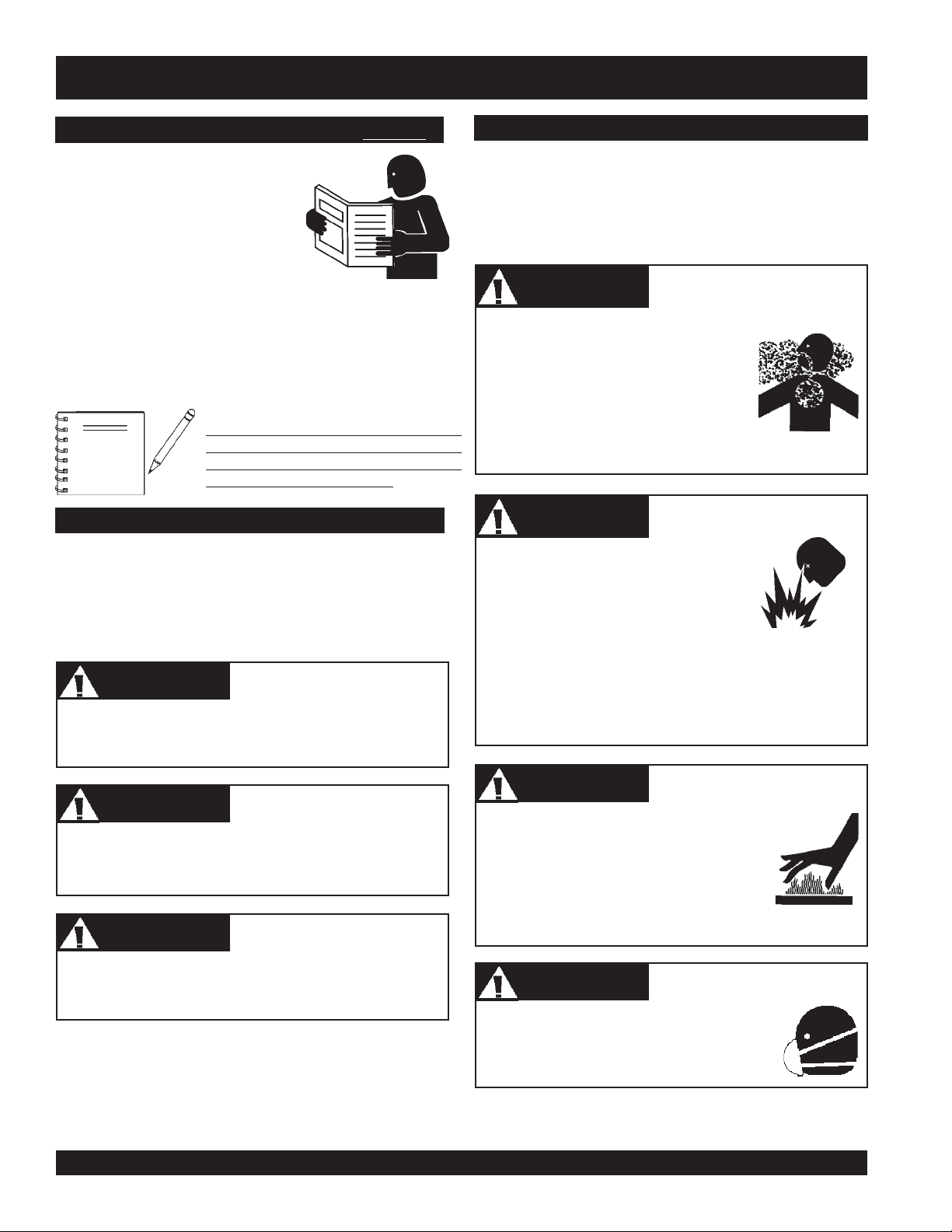
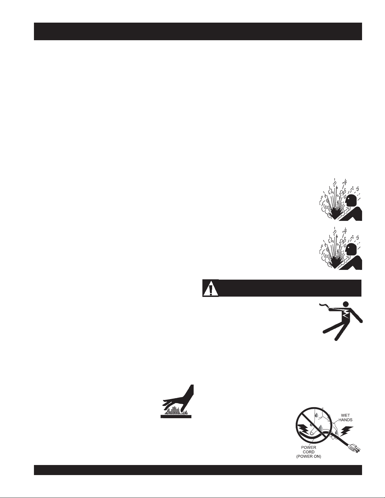
Engine exhaust gases contain
poisonous carbon monoxide. This gas
is colorless and odorless, and can
cause death if inhaled. NEVER operate
this equipment in a confined area or
enclosed structure that does not provide
ample free flow air.
Diesel Fuel is extremely flammable,
and its vapors can cause an explosion
if ignited. DO NOT start the engine near
spilled fuel or combustible fluids.
Lethal Exhaust Gases
WARNINGWARNING
WARNING
WARNINGWARNING
WARNINGWARNING
WARNING
WARNINGWARNING
Lethal Exhaust Gas Hazards
Explosive Fuel Hazards
DANGERDANGER
DANGER
DANGERDANGER
You WILL be
if you DO NOT follow these directions.
WARNINGWARNING
WARNING
WARNINGWARNING
You CAN be KILLED or
you DO NOT follow these directions.
CAUTICAUTI
CAUTION
CAUTICAUTI
You CAN be
these directions.
KILLED
INJURED
if you DO NOT follow
or
SERIOUSLY INJURED
SERIOUSLY INJURED
if
DO NOT fill the fuel tank while the engine is running or
hot. DO NOT overfill tank, since spilled fuel could ignite if
it comes into contact with hot engine parts or sparks from
the ignition system. Store fuel in approved containers, in
well-ventilated areas and away from sparks and flames.
WARNINGWARNING
WARNING
WARNINGWARNING
Engine components can generate extreme
heat. To prevent burns, DO NOT touch
these areas while the engine is running or
immediately after operations. Never
operate the engine with heat shields or heat
guards removed.
WARNINGWARNING
WARNING
WARNINGWARNING
ALWAYS wear approved
protection when required.
Burn Hazards
Respiratory Hazards
respiratory
PAGE 6 —SDW-225SS WELDER/GENERATOR— OPERATION & PARTS MANUAL — REV. # 2 (10/07/05)
Page 7
SDW-225SS — SAFETY MESSAGE ALERT SYMBOLS
CAUTIONCAUTION
CAUTION
CAUTIONCAUTION
NEVER operate equipment with covers,
or guards removed. Keep fingers, hands,
hair and clothing away from all moving
parts to prevent injury.
CAUTIONCAUTION
CAUTION
CAUTIONCAUTION
ALWAYS place the power source, circuit
breakers or ON/OFF switch in the OFF
position, when the generators is not in use,
unless connected to transfer switch.
CAUTIONCAUTION
CAUTION
CAUTIONCAUTION
ALWAYS wear approved eye and
hearing protection.
Rotating Parts Hazards
Accidental Starting Hazards
Eye and Hearing Hazards
CAUTIONCAUTION
CAUTION
CAUTIONCAUTION
Other important messages are provided throughout this
manual to help prevent damage to your portable generator,
other property, or the surrounding environment.
Equipment Damage
Hazards
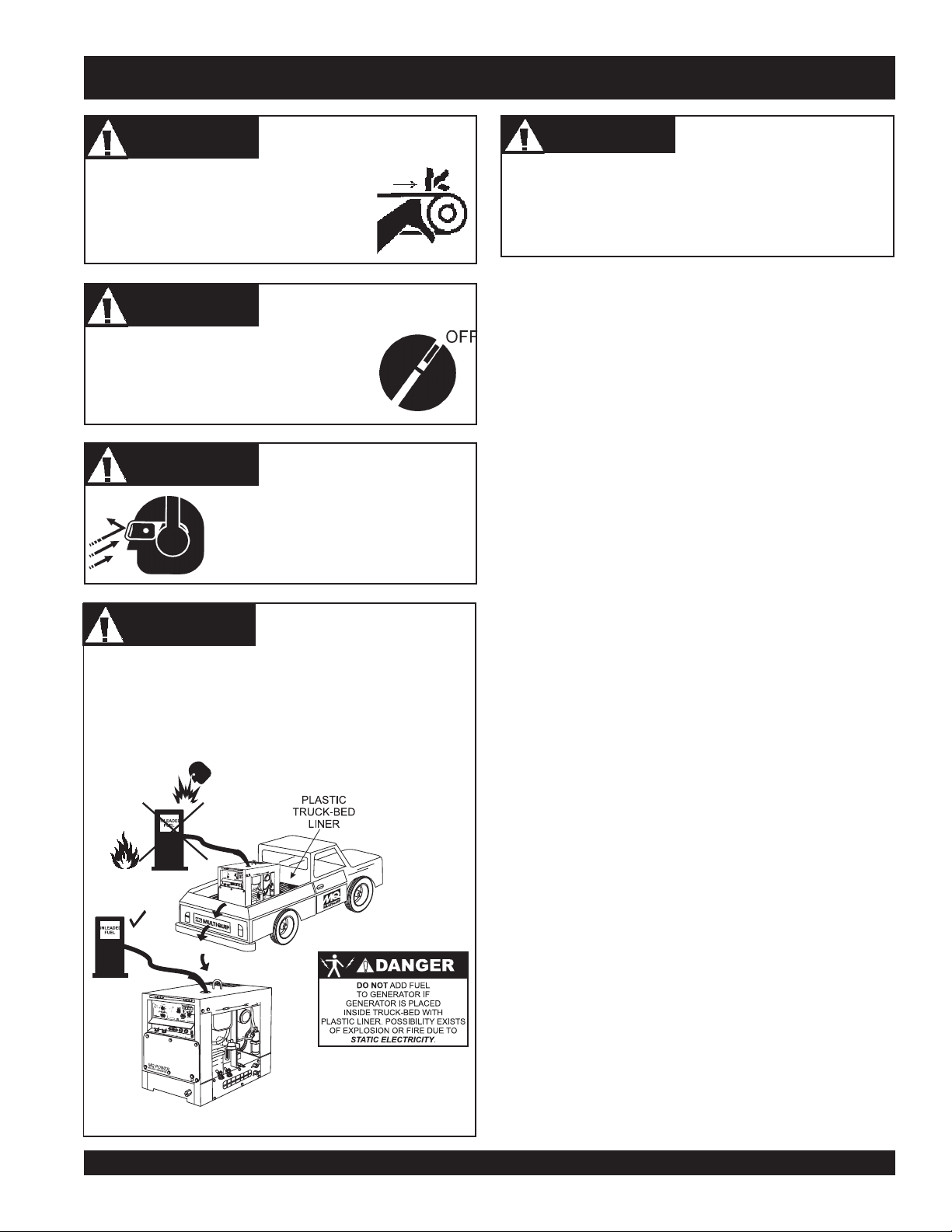
DANGERDANGER
DANGER
DANGERDANGER
NEVER refuel welder/generator when placed in truck bed
with plastic liner. The possibility exists of explosion due to
static electricity. When adding fuel, remove welder/
generator from truck bed and place on ground.
Refueling Hazard
SDW-225SS WELDER/GENERATOR — OPERATION & PARTS MANUAL — REV. #2 (10/07/05) — PAGE 7
Page 8
SDW-225SS — RULES FOR SAFE OPERATION
■
DANGERDANGER
DANGER
DANGERDANGER
Failure to follow instructions in this manual may lead
to serious injury or even death! This equipment is to
be operated by trained and qualified personnel only!
This equipment is for industrial use only.
The following safety guidelines should always be used when
operating the SDW-225SS Welder/Generator:
GENERAL SAFETY
■
DO NOT operate or service this
equipment before reading this entire
manual.
■
This equipment should not be operated by persons under
18 years of age.
■
NEVER operate this equipment without proper protective
clothing, shatterproof glasses, steel-toed boots and other
protective devices required by the job.
■
NEVER operate this equipment when not
feeling well due to fatigue, illness or taking
medicine.
■
NEVER operate this equipment under the influence of
drugs
or
alcohol
.
Read this manual!
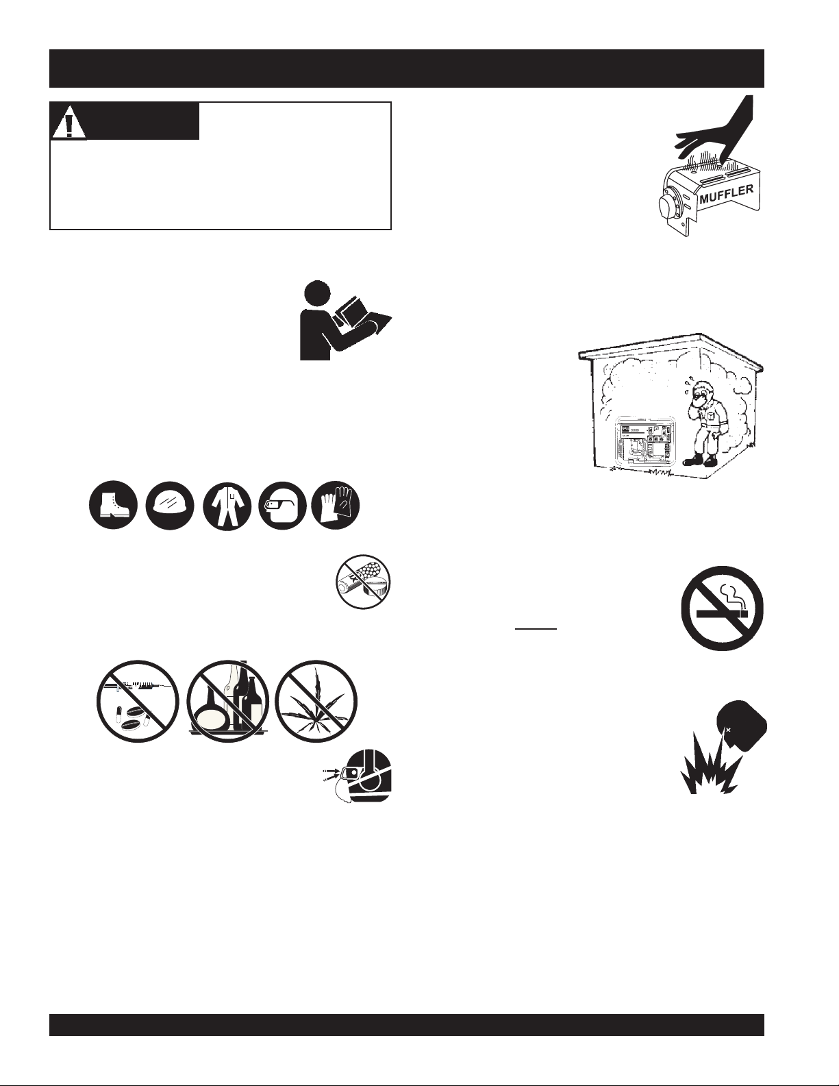
NEVER touch the hot exhaust
manifold, muffler or cylinder. Allow
these parts to cool before servicing
engine or generators.
■
The engine section of this welder/generator requires an
adequate free flow of cooling air.
welder/generator in any enclosed or narrow area where
free flow of the air is
restricted. If the air flow
is restricted it will cause
serious damage to the
generators or engine and
may cause injury to
people. Remember the
welder/generator's
engine gives off
DEADLY
■
ALWAYS refuel in a well-ventilated area, away from sparks
and open flames.
■
ALWAYS use extreme caution when
working with flammable liquids. When
refueling, stop the engine and allow it to
cool. DO NOT
machine. Fire or explosion could result
from fuel vapors, or if fuel is spilled on a
hot engine.
carbon monoxide gas.
smoke
around or near the
NEVER
operate the
■
■
ALWAYS wear proper respiratory (mask),
hearing and eye protection equipment when
operating the generator.
■
Whenever necessary, replace nameplate, operation and
safety decals when they become difficult read.
■
Manufacturer does not assume responsibility for any
accident due to equipment modifications.
■
NEVER use accessories or attachments, which are not
recommended by Multiquip for this equipment. Damage
to the equipment and/or injury to user may result.
PAGE 8 —SDW-225SS WELDER/GENERATOR— OPERATION & PARTS MANUAL — REV. # 2 (10/07/05)
■
■
NEVER operate the welder/generator in
an explosive atmosphere or near
combustible materials. An explosion or
fire could result causing severe
bodily
harm or even death.
NEVER disconnect any
These devices are intended for operator safety. Disconnection
of these devices can cause severe injury, bodily harm or even
death! Disconnection of any of these devices will void all
warranties.
ALWAYS be sure the operator is familiar with proper safety
precautions and operation techniques before using welder/
generator.
"emergency or safety devices"
.
Page 9
SDW-225SS — RULES FOR SAFE OPERATION
■
NEVER leave the welder/generator unattended. Turn off
engine when unattended.
■
Unauthorized equipment modifications will void all
warranties.
■
ALWAYS ensure welder/generator is on level ground before
use.
■
DO NOT place hands or fingers inside welder/generator's
engine compartment when engine is running.
■
NEVER run engine without air cleaner. Severe engine damage
may occur.
■
NEVER change or adjust the engine speed which has been
set at the factory prior to shipping.
Power Cord Safety
■
NEVER let power cables or cords
■
NEVER
is being transfer to a load.
■
NEVER use a defective or frayed power cable. Check the
cable for cuts in the insulation.
stand in water
while AC power from the generator
lay in wate
r.
■
■
■
■
■
■
■
ALWAYS replace any worn or damaged warning decals.
ALWAYS store equipment properly when it is not being used.
Equipment should be stored in a clean, dry location out of the
reach of children and unauthorized personnel.
The electrical voltage required to operate the generator can
cause severe injury or even death through physical contact
with live circuits.
performing maintenance on the generator.
Dispose of hazardous waste properly. Examples of potentially
hazardous waste are used motor oil, fuel and fuel filters.
DO NOT use food or plastic containers to dispose of
hazardous waste.
DO NOT pour waste, oil or fuel directly onto the ground,
down a drain or into any water source.
Removing the engine oil drain plug while
the engine is hot will result in hot oil to gush
out of the oil drain plug, therefore causing
severe scalding to any persons in the general
area of the generator.
Turn all circuit breakers OFF before
■
NEVER use a extension cord that is frayed or damaged where
the insulation has been cut.
■
ALWAYS make certain that proper power or extension cord
has been selected for the job.
■
Grounding Safety
■
ALWAYS make sure that electrical circuits are properly
grounded
local codes before operating generator. Severe
death!
ungrounded generator.
■
ALWAYS make sure the generators are properly grounded to
a suitable earth ground (GROUND ROD). See installation in
this manual.
■
NEVER use
per the
by electrocution can result from operating an
National Electrical Code
gas piping
as an electrical ground.
(NEC) and
injury
or
Maintenance Safety
■
NEVER lubricate components or attempt service on a running
machine.
■
High Temperatures – Always stop engine and
allow the engine to cool before adding fuel, oil
or performing service and maintenance
hot!
functions. Contact with
cause serious burns.
■
Keep the machinery in proper running condition.
■
Fix damage to the machine immediately and replace any
broken parts immediately.
components can
Removing the radiator plug while the engine
is hot will result in hot water or coolant to
gush out of the radiator, therefore causing
severe scalding to any persons in the general
area of the generator.
DANGERDANGER
DANGER
DANGERDANGER
During operation of this generator, there
exists the possibility of
electrical shock or burn
cause
DEATH!
To avoid these hazards:
severe bodily harm
NEVER use
ELECTROCUTION HAZARDSELECTROCUTION HAZARDS
-
ELECTROCUTION HAZARDS
ELECTROCUTION HAZARDSELECTROCUTION HAZARDS
damaged
or
electrocution
, which can
or even
worn
,
cables when connecting
equipment to the generator. Make sure power connecting
cables are securely connected to the generator’s output
receptacles, incorrect connections may cause damage
to the generators and electrical
shock.
NEVER grab or touch a live
power cord with wet hands, the
possibility exist of electrical
shock, electrocution, and even
death!
SDW-225SS WELDER/GENERATOR — OPERATION & PARTS MANUAL — REV. #2 (10/07/05) — PAGE 9
Page 10
SDW-225SS — RULES FOR SAFE OPERATION
NEVER insert any objects into
■
the output receptacles during
operation. This is extremely
dangerous. ALWAYS turn-off
the generators and place all
■
circuit breakers in the “OFF”
position when contact with the
output receptacles is required. There exist the possibility
of
electrocution, electrical shock or burn, which can
cause severe bodily harm or even death
Backfeed to a utility system can cause
electrocution
NEVER connect the generator to a
building's electrical system without a
transfer switch or other approved device.
All installations should be performed by
licensed electrician
a
with all applicable laws and electrical
codes. Failure to do so could result in
electrical shock or burn causing serious
injury or even death!
and or property damage.
in accordance
!
■
■
■
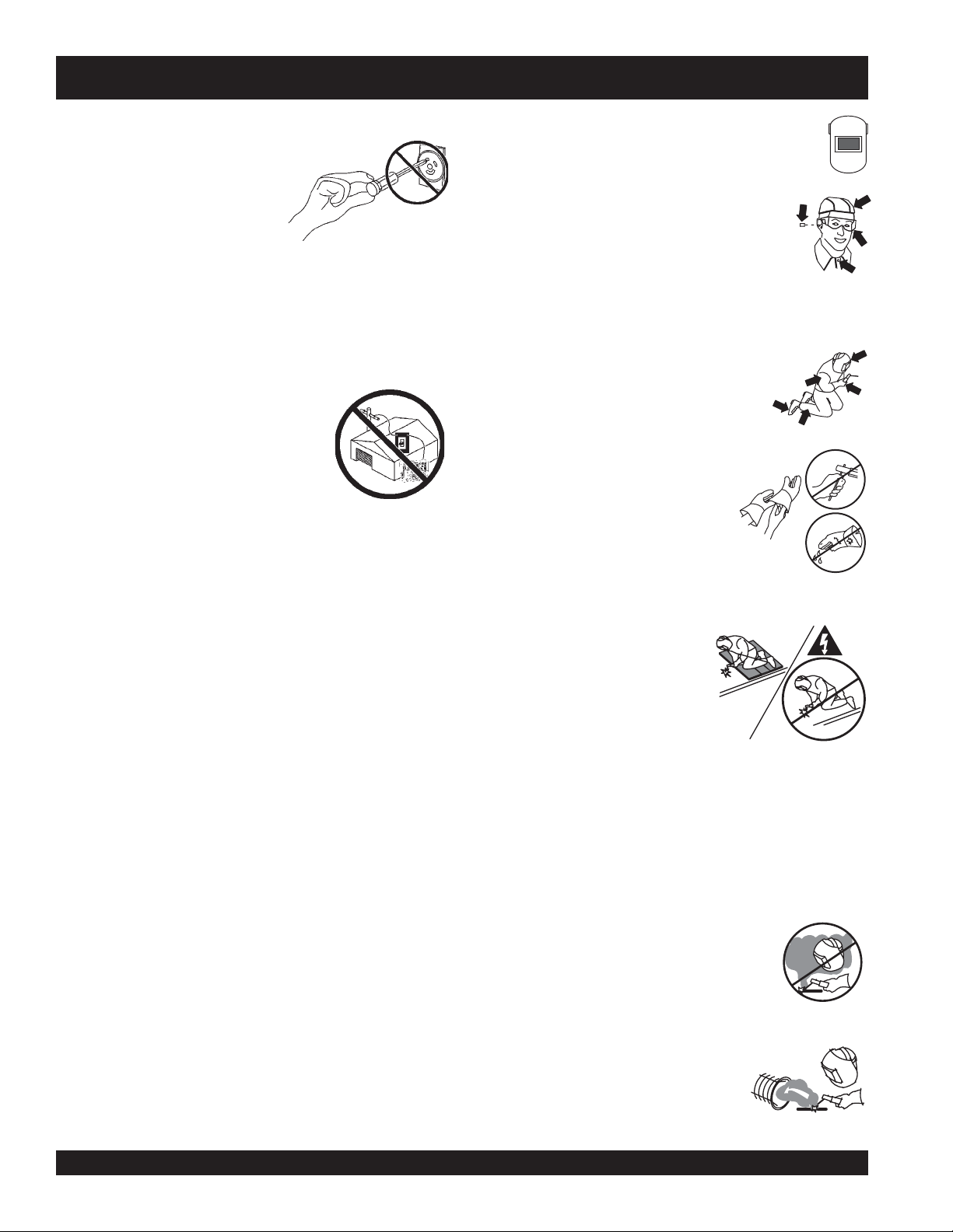
ALWAYS protect your eyes from rays of the arc. Wear
a head shield with proper filter plates when welding.
ALWAYS wear welder cap and approved
safety glasses with side shields.ALWAYS use
ear protection when welding out of position or
in confined spaces.
ALWAYS wear protective chipping goggles when chipping
off weld slag. Chip away from your face.
ALWAYS wear complete body protection
such as leather gloves, an apron or sleeves
to shield against the arc rays and sparks.
Button up shirt collar.
ALWAYS wear dry, hole-free
insulating gloves and body protection.
Do not touch electrode with bare hand.
Do not wear wet or damaged gloves.
Welding Safety
■
ALWAYS keep welder in good, clean, dry condition.
■
ALWAYS make sure all eledtrical connections are tight, clean,
and dry.
■
ALWAYS use correct size welding cable. NEVER overload.
■
ALWAYS make sure cables, holder and connections are
properly insulated.
■
ALWAYS cut off power to welders before cleaning machine
or making internal adjustments.
■
NEVER change polarity while machine is under load.
■
ALWAYS observe normal operating care for electrical
hazards.
■
ALWAYS keep work area neat , clean, and dry.
■
ALWAYS dispose hot electrode stubs in a metal container.
■
NEVER strike an arc on a compressed gas cylinder.
■
ALWAYS protect yourself from
electric shock by insulating
yourself from work and ground.
Use non-flammable, dry insulating
material if possible, or use dry
rubber mats, dry wood or plywood,
or other dry insulating material big
enough to cover your full area of
contact with the work or ground.
■
ALWAYS use a non-reflectingwelding curtain to protect others
in the area from arc rays.
■
ALWAYS make sure you work area has adequate ventilation
and plenty of fresh air. Special precautions are necessary
when welding lead, zinc, beryllium copper or cadmium.
■
ALWAYS keep your head out of the fumes.
Do not breathe the fumes. Use enough
ventilation, exhaust at the arc, or both, to keep
fumes and gases from your breathing zone
and the general area.
■
ALWAYS use enough forced ventilation
or loca exhaust (forced suction) at the
arc to remove the fumes from your
breathing area.
PAGE 10 —SDW-225SS WELDER/GENERATOR— OPERATION & PARTS MANUAL — REV. # 2 (10/07/05)
Page 11
SDW-225SS — RULES FOR SAFE OPERATION
■
ALWAYS use a ventilating fan to
remove fumes from the breathing
zone an welding area.
■
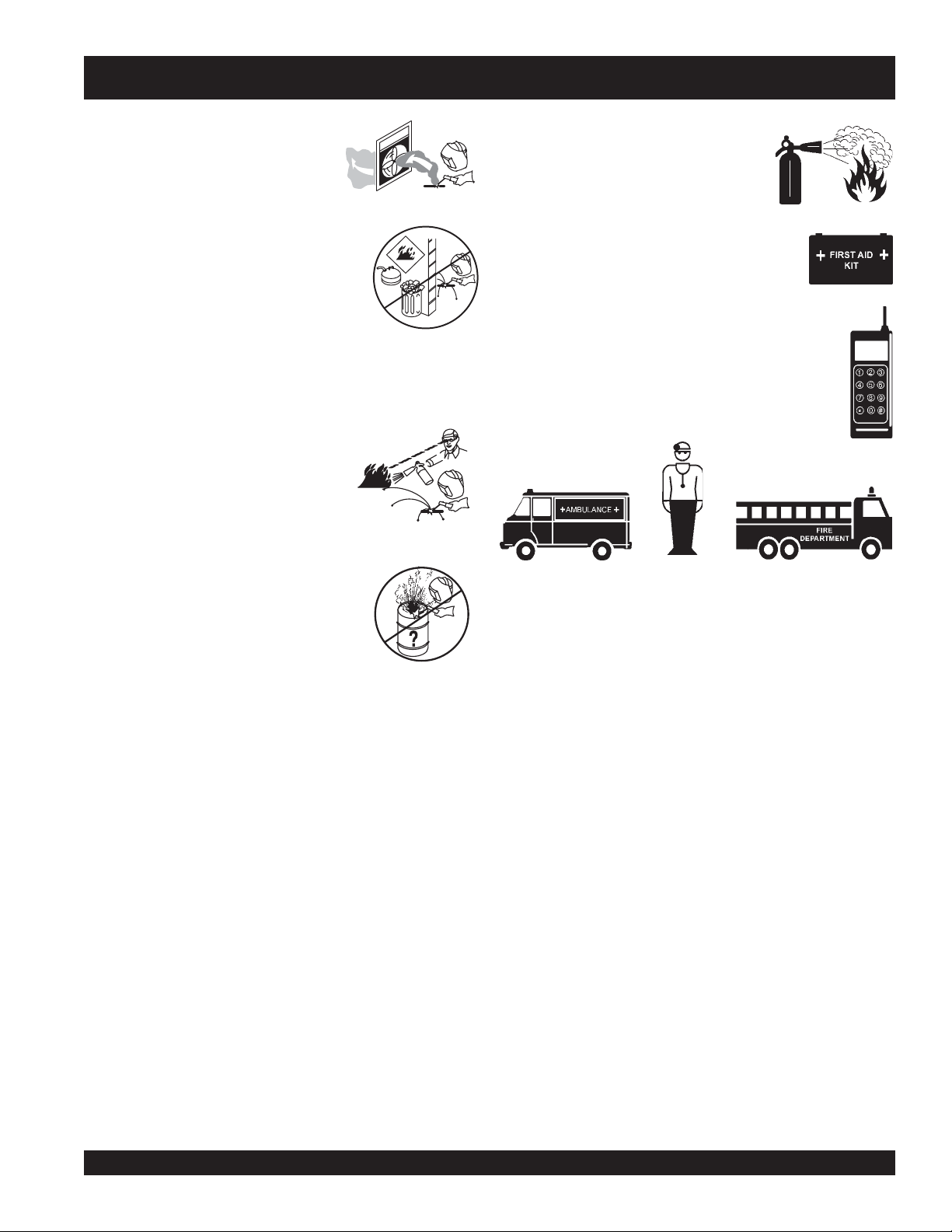
NEVER weld near flammable material.
Move flammables at 35 feet (11 meters)
away or protect them with flame-proof
covers.
■
NEVER weld near engine fuel. Engine fuel plus flames or
sparks can cause fire or explosion.
■
Welding sparks can cause fires.
ALWAYS have a fire extinguisher
nearby, and have a trained fire watcher
ready to use it.
Emergencies
■
ALWAYS know the location of the
nearest
■
ALWAYS know the location of the nearest
first aid kit
■
fire extinguisher
.
In emergencies
nearest phone or
Also know the phone numbers of the nearest
always
ambulance, doctor
information will be invaluable in the case of an
emergency.
.
know the location of the
keep a phone on the job site
and
fire department
.
. This
■
NEVER weld on drums, tanks, or any
closed containers unless a qualified
person has tested it and declared it or
prepared it to be safe.
SDW-225SS WELDER/GENERATOR — OPERATION & PARTS MANUAL — REV. #2 (10/07/05) — PAGE 11
Page 12
SDW-225SS — OPERATION AND SAFETY DECALS
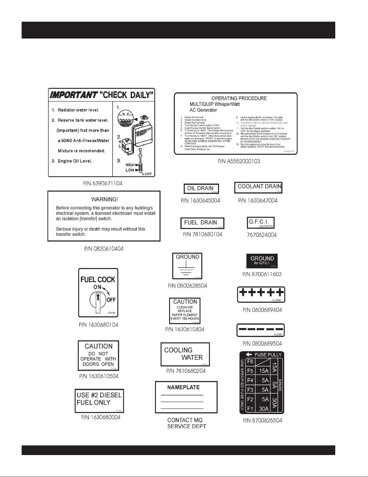
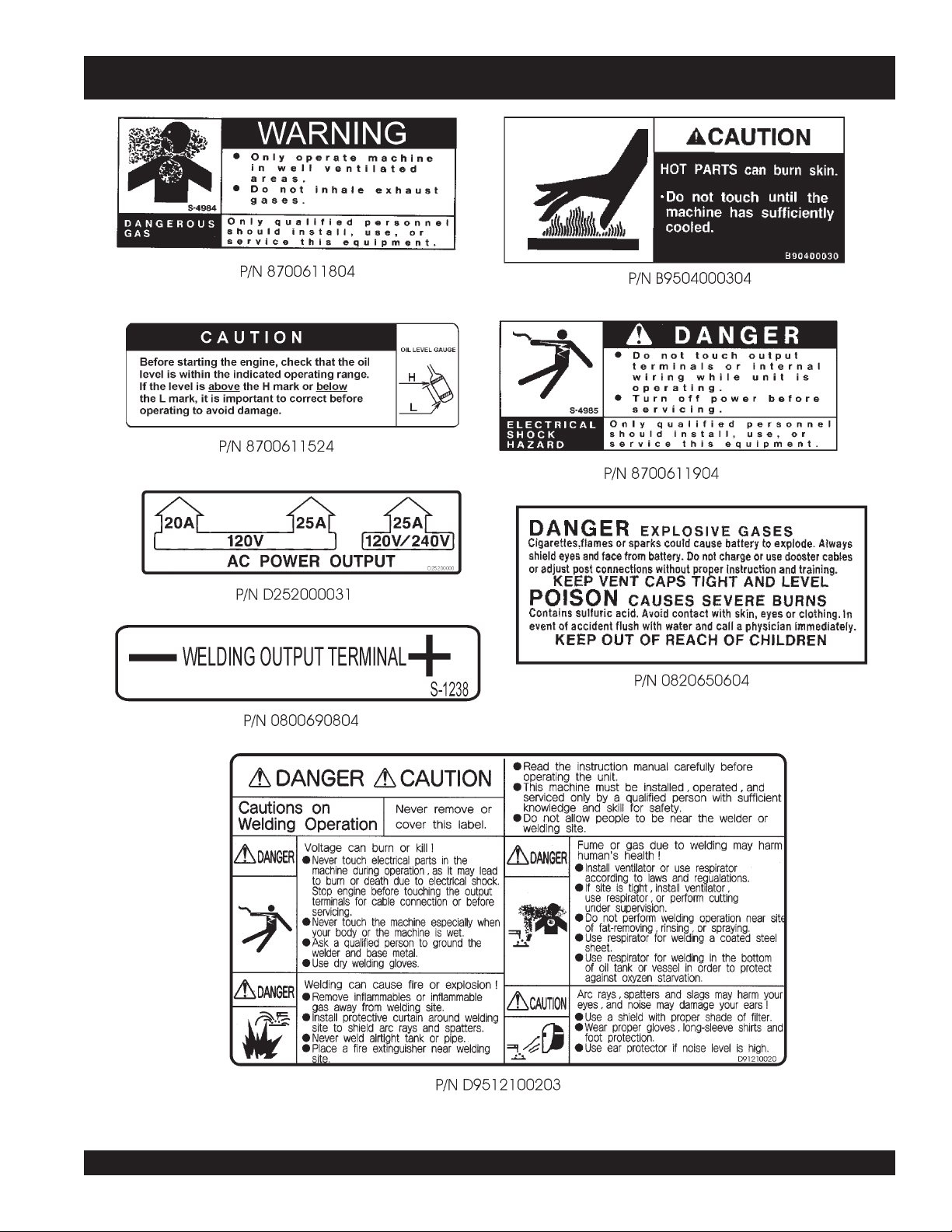
Machine Safety Decals
The SDW-225SS welder/generator is equipped with a number of safety decals. These decals are provided for operator safety and
maintenance information. The illustration below shows these decals as they appear on the machine. Should any of these decals
become unreadable, replacements can be obtained from your dealer.
PAGE 12 —SDW-225SS WELDER/GENERATOR— OPERATION & PARTS MANUAL — REV. # 2 (10/07/05)
Page 13
SDW-225SS — OPERATION AND SAFETY DECALS
SDW-225SS WELDER/GENERATOR — OPERATION & PARTS MANUAL — REV. #2 (10/07/05) — PAGE 13
Page 14

SDW-225SS — SPECIFICATIONS
snoitacificepS.1elbaT
snoitacificepSrotareneG
ledoM SS522-WDS
esahP esahPelgniS
seriW )dednuorGlartueN(seriW
tuptuOnumixaM sttaW0006
egatloVdetaR stloV042/021
ycneuqerF zH06
deepS mpr0063
rotcaFrewoP 0.1
gnitaR suounitn
snoitacificepSredleW
)CC/VC(rewoPtuptuOdetaR Wk6.5/Wk0.4
)CC/VC(egatloVtuptuOdetaR spmA002
CtuptuOdetaR stloV82/02
elcyCytuD %/001
deepSdetaR MPR0063
egnaRegatloV stloV82-51
egnaRtnerruC spmA522-05
ledoM BE-284-ZATOBUK
epyT elcyC-4,lacitreV
tuptuOdetaR
tnemecalpsiD )cc
metsySgnilooC delooC-retaW
metsySgnitratS tratScirtcelE
yrettaB hA53-V21
leuF 2.oNleuFleseiD
gieW )gk1.35(.sbl1.711
th
)CC/VC(tnerru
tacificepSenignE
snoi
srednilyCforebmuN 2
yticapaCknaTleuF s
yticapaCtnalooC sretil5.2/lag66.0
yticapaCliOebuL sretil1.2/lag55.0
noitpmusnoCleuF .rh/)sre
)HxWxL(snoisnemiD
-3
oC
PH9.11/Wk9.8
mpr0063@
974(ni.uc32.92
retil52/lag6.6
til36.2(lag96.0
mm025x983x153
)ni74.02x13.51x28.31(
The maximum output of the engine listed above is applicable to supplying electrical power for continuous service at ambient
conditions in accordance with SAE Test cord J607. The above ambient conditions are at standard sea level, with a barometric
reading of 29.92 inches and a temperature of 60° F.
°°
°
°°
Generally, the engine output power will decrease 3 1/2% for each 1000 feet of altitude above sea level, and 1% for each 10
°°
°
the standard temperature of 60
°°
F.
F above
PAGE 14 —SDW-225SS WELDER/GENERATOR— OPERATION & PARTS MANUAL — REV. # 2 (10/07/05)
Page 15

SDW-225SS — GENERAL INFORMATION
SDW-225SS FAMILIARIZATION
Generator
The MQ Power Model SGW-250SS welder/generator can
provide 200 amps of welding current when in the CV/DC
mode and 225 amps of welding current when in the CC/DC
mode. When used as a generator it can provide a maximum
of 6,000 watts of AC power.
Control Panel
The
control panel
z
One GFCI 120 volt receptacle, 20 amp (single-phase)
z
One 120 volt receptacle, 30 amp (single-phase)
z
One 120/240 volt receptacle, 30 amp (single-phase)
z
Main Circuit Breaker 240V @25 Amps
z
Circuit Protector Breaker (GFCI) 120V @20 Amps
z
Idle Control Switch
z
Starter Switch
z
Warning Lamp Unit
z
Hour Meter
z
Ground Terminal
z
DC (Welding) Output Terminal
Engine Protection System
Engine protection fail safe features are provided in the event
of low oil pressure, high coolant temperature and failure of
the battery to charge. If any of the above conditions occur
while operating the generator it will cause a complete unit
shut down.
Battery Charge Alarm
This unit is equipped with a protective device that signals
an alarm and automatically stops the engine when the battery
cannot be charged by the alternator.
Water Temperature Alarm
This unit is equipped with an apparatus that signals an alarm
and automatically stops the engine when the cooling water
temperature becomes abnormally high. This apparatus will
not function properly if the machine is operated with less
than the proper amount of coolant.
Oil Pressure Warning Alarm
In the event of low oil pressure (engine), this welder/
generator is equipped with an engine protection fail safe
system. If low oil pressure is detected while operating the
welder/generator, the engine protection system will shut down
the engine.
is provided with the following:
If this condition (low oil pressure) should occur, please refer
to the engine troubleshooting table in this manual.
Welder Protection System
In the event of an overload, this welder/generator is equipped
with a welder protection system. If an overload is detected
while operating the welder/generator, the welder protection
system will shut down the engine.
Open Delta Excitation System
The SDW-225SS generator is equipped with the state of the
art "
Open-Delta
consist of an electrically independent winding wound among
stationary windings of the AC output section.
There are four connections of the open delta A, B, C and D.
During steady state loads, the power from the voltage
regulator is supplied from the parallel connections of A to B,
A to D, and C to D. These three phases of the voltage input
to the voltage regulator are then rectified and are the
excitation current for the exciter section.
When a heavy load, such as a motor starting or a short
circuit occurs, the automatic voltage regulator (AVR)
switches the configuration of the open delta to the series
connection of B to C. This has the effect of adding the
voltages of each phase to provide higher excitation to the
exciter section and thus better voltage response during the
application of heavy loads.
The connections of the AVR to the AC output windings are
for sensing only. No power is required from these windings.
The open-delta design provides virtually unlimited excitation
current, offering maximum motor starting capabilities. The
excitation does not have a "
according the demands of the required load.
Engine
The SDW-225SS is powered by a 4-cycle KUBOTA
engine. This engine is designed to meet every performance
requirement for generator. Refer to Table 1 for engine
specifications.
In keeping with Multiquip's policy of constantly improving
its products, the specifications quoted herein are subject to
change without prior notice.
Figures 2 and 3 show the basic controls and indicators for
the SDW-225SS welder/generator.
" excitation system. The open delta system
fixed ceiling
" and responds
diesel
SDW-225SS WELDER/GENERATOR — OPERATION & PARTS MANUAL — REV. #2 (10/07/05) — PAGE 15
Page 16
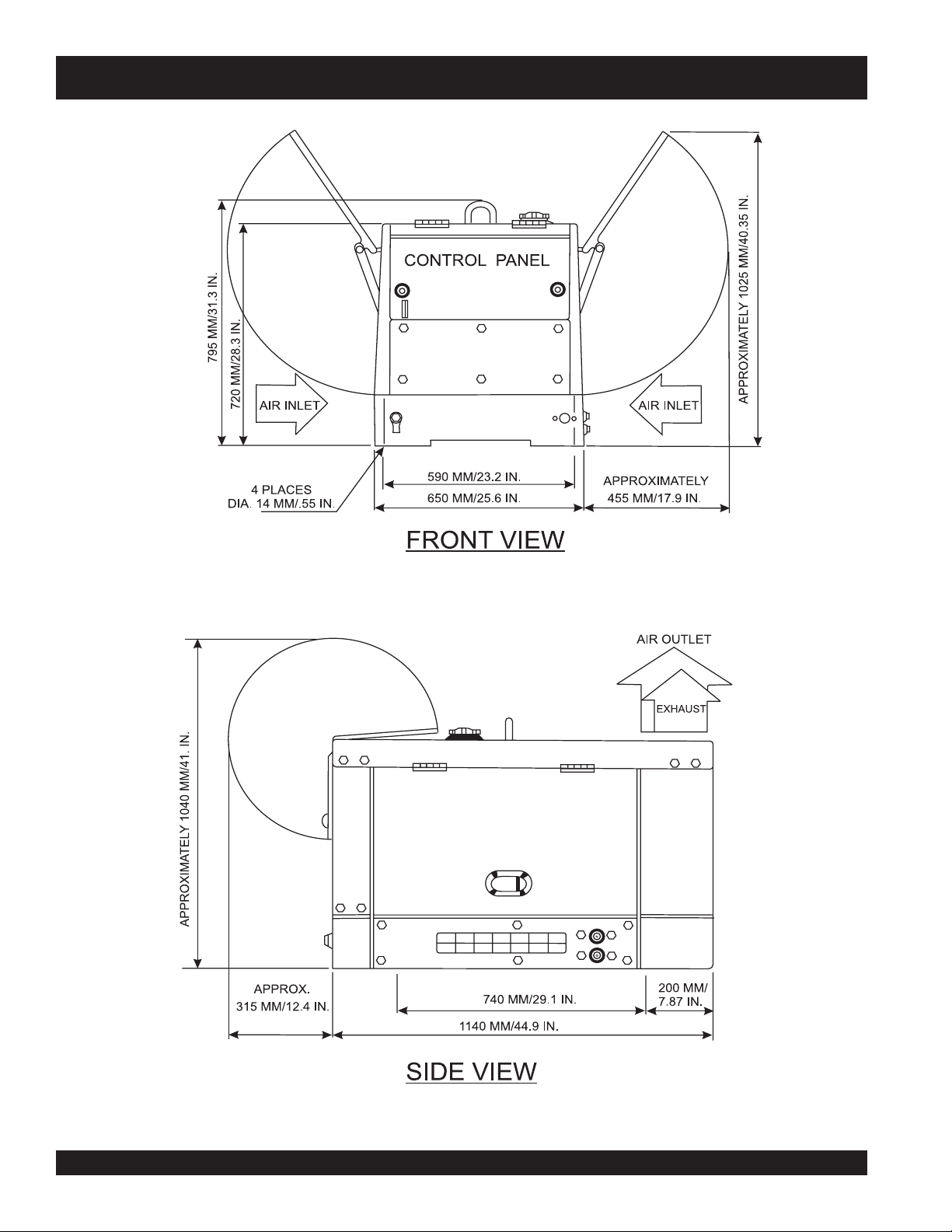
SDW-225SS — DIMENSIONS
Figure 1. SDW-225SS Dimensions
PAGE 16 —SDW-225SS WELDER/GENERATOR— OPERATION & PARTS MANUAL — REV. # 2 (10/07/05)
Page 17
SDW-225SS — CONTROLS AND INDICATORS
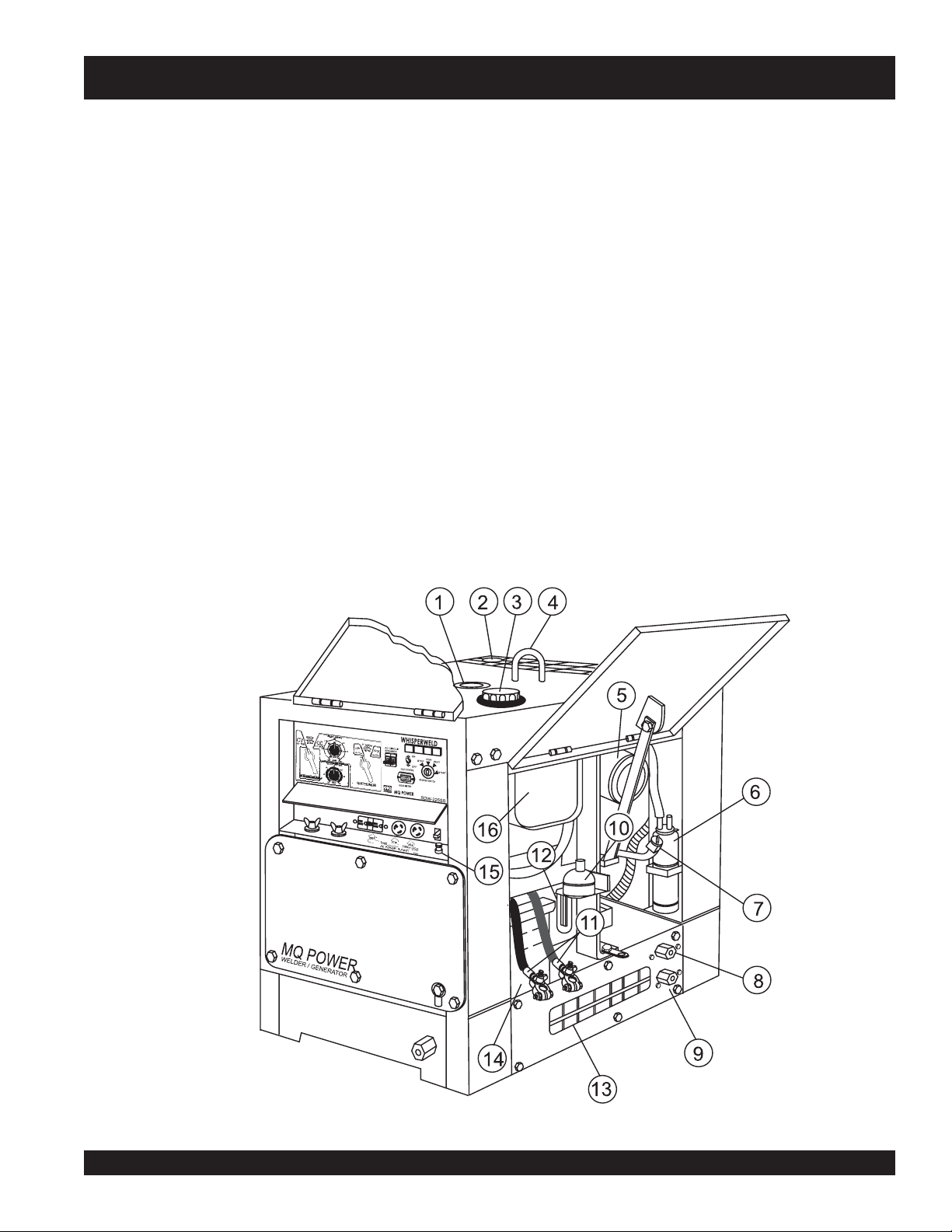
Figures 2 and 3 show the location of the controls and indicators.
The functions of each control or indicator is described below
and on the preceding page.
1. Fuel Gauge – Indicates the amount of fuel in the fuel tank.
2. Air Outlet and Exhaust – Allows engine exhaust to exit
the generator into the open air. NEVER block this opening.
3. Fuel Cap – Remove this cap to add fuel. Add only #2
diesel fuel
the tank. DO NOT top off. Wipe up any spilled fuel
immediately.
4. Lifting Hook – Use this hook to lift the generator.
5. Engine Air Cleaner – Prevents dirt and other debris from
entering the fuel system. Lift locking latch on air filter
cannister to gain access to filter element.
6. Overflow Bottle – Supplies coolant to the radiator when
radiator coolant level is low. Fill to indicated level as shown
on bottle.
7. Engine Oil Filler Port – Remove this cap to add engine
oil. Use only recommended type oil. See table 3.
8. Coolant Drain Plug – Remove this plug to drain coolant
from the radiator.
. Always keep an adequate amount of fuel in
9. Oil Drain Plug – Remove this plug to drain oil from the
engine.
10. Automatic Speed Control Solenoid – Automatically
returns the engine speed to idle when no load is present.
11. Battery Terminals – Connect these terminals to the battery.
Always pay close attention to the polarity of the terminals
when connecting to the battery, RED (positive), and BLACK
(negative).
12. Fuel Filter – Prevents dirt and other debris from entering
the fuel system. Change fuel filter as recommended in the
maintenance section of this manual.
13. Air Inlet Vent – Allows outside air to enter the generator.
NEVER block this opening.
14. Battery – Provides 12 VDC power for the generator. When
replacing battery (12V 35 AH) use only recommended type
battery.
15. G.F.C.I Ground Terminal – Use this terminal to connect
external equipment grounds so that the GFCI receptacle
will have a ground path.
16. Fuel Tank – Holds 6.6 gallons (25 liters) of diesel fuel.
Figure 2. SDW-225SS Components 1
SDW-225SS WELDER/GENERATOR — OPERATION & PARTS MANUAL — REV. #2 (10/07/05) — PAGE 17
Page 18
SDW-225SS — CONTROLS AND INDICATORS
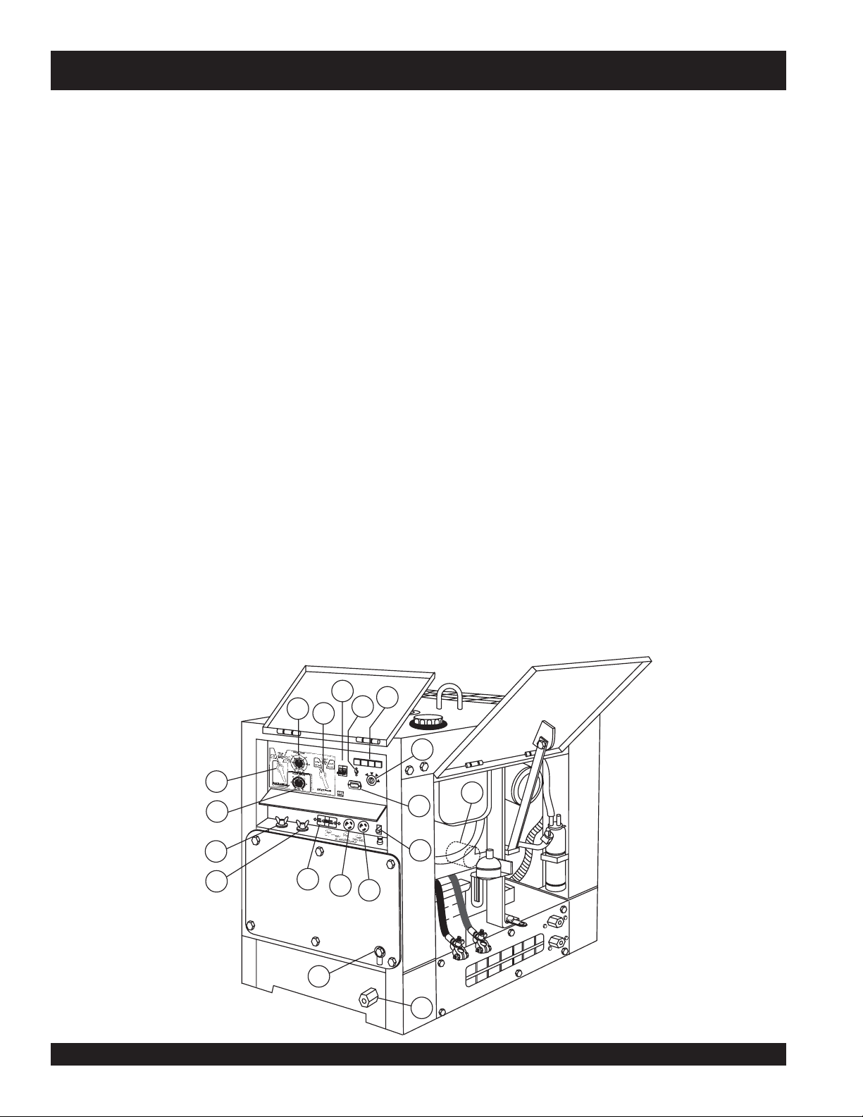
17. Fuel Drain Plug – Remove this plug to drain fuel from the
27. Idle Control Switch – Regulates the engine speed when
fuel tank.
18. Frame Ground Lug – Connect a ground strap between
28. Warning Lamp Display – Includes the following lamps.
this lug and a ground rod. Make sure that the ground rod is
inserted deep into the ground to provide a good earth
ground. Consult with local Electrical and Safety Codes for
proper connection and depth of ground rod.
19. Oil Filter – Provides oil filtering for the engine.
20. Hour Meter – Indicates number of hours machine has
been in use or hours engine was run.
21. Current Control (CC) Adjustment Knob – Use this
control to adjust the welding current between 50 to 225
amps. This function will not work in the CV mode.
22. Voltage Control (CV) Adjustment Knob – Use this
29. Ignition Switch – With key inserted, turn clockwise to
control to adjust the welding voltage between 15 to 28 V.
This function will not work in the CC mode.
30. Positive Welding Output Terminal – Connect the
23. Welding Type (Wire/Stick) Selector Switch (CV/CC) –
Turn this selector switch toeither CV or CC for welding.
DO NOT turn this switch under load.
31. Negative Welding Output Terminal – Connect the
24. Current Range Selector Switch (CC) – Turn this selector
switch to either low or high for welding. DO NOT turn this
switch under load.
25. Main Circuit Breaker – This 2-pole circuit breaker provides
32. Receptacle G.F.C.I. – This receptacle provides 120 volts
circuit protection (250V @25 amps) for the Electric Parts
Assembly.
26. Circuit Protector Circuit Breaker – This single pole circuit
33. Receptacle – Provides 120 volts output at 25 amps.
34. Receptacle – Provides 120/240 volts output at 25 amps.
breaker provides circuit protection (120V @20 amps) for
the G.F.C.I receptacle.
the generator is under load.
z
Low Oil Pressure Lamp - lights to indicate that
the engine pressure has fallen below acceptable
level.
z
High Water Temperature Lamp - lights to indicate
°
that the water temperature has exceeded 239
z
Electrical System Lamp - lights when the electrical
F.
system is not charging properly.
z
Pre-heat Lamp- when the key switch is set to the
pre-heat position, this lamp turns on. When the lamp
turns off, the key switch can be turned to the start
position.
start engine.
welding cable to this terminal. Select the appropriate
polarities according to the application. See Table 7.
negative cable of the welding source to this terminal. Select
the appropriate polarities according to the application. See
Table 7.
output at 20 amps.
23
22
30
31
21
32
MQ POWER
WELDER / GENERATOR
25
24
33
27
WHISPERWELD
A
C
C
IR
C
U
IT
B
R
E
A
K
E
R
I
D
L
E
C
O
N
00
0
0
0
H
O
U
R
S
H
O
U
R
M
E
T
E
MQ POWER
O
O
T
R
O
R
N
S
T
O
F
F
L
S
T
A
SDW-225SS
D
2
5
2
0
0
0
0
0
34
28
29
R
U
N
P
H
E
A
T
S
T
A
R
T
R
T
E
R
S
W
IT
C
H
19
20
26
18
17
Figure 3. SDW-225SS Components 2
PAGE 18 —SDW-225SS WELDER/GENERATOR— OPERATION & PARTS MANUAL — REV. # 2 (10/07/05)
Page 19

SDW-225SS — TRAILER-10 MAINTENANCE
The SDW-225SS welder/generator can be mounted on a
Trailer-10.
Trailer Maintenance
This section is intended to provide the user with service and
maintenance information for the Trailer-10.
Periodic inspection of the trailer will ensure safe towing of
the generator and will prevent personal injury and damage to
the equipment.
The definitions below describe some of the major components
of a Trailer-10 that would be used with the SDW-225SS welder/
generator.
1. GVWR- Gross Vehicle Weight Rating (GVWR) is the
maximum number of pounds the trailer can carry.
2. Frame Length - Measurement is from the ball hitch to
the rear bumper (reflector).
3. Frame Width - Measurement is from fender to fender.
4. Jack Stand - Trailer support device with maximum pound
requirement from the tongue of the trailer.
5. Coupler - Type of hitch used on the trailer for towing.
6. Tire Size - Indicates the diameter of the tire in inches
(10,12,14, etc.), and the width in millimeters
(175,185,205, etc.). The tire diameter must match the
diameter of the tire rim.
9. Tire Ply - The tire ply (layers) number is rated in letters;
2-ply,4-ply,6-ply, etc.
10. Wheel Hub - The wheel hub is connected to the trailer’s
axle.
11. Tire Rim - Tires mounted on a tire rim. The tire rim must
match the size of the tire.
12. Lug Nuts - Used to secure the wheel to the wheel hub.
Always use a torque wrench to tighten down the lug
nuts. See Table 5 and Figure 5
sequence.
13. Axle - Indicates the maximum weight the axle can sup-
port in pounds, and the diameter of the axle expressed
in inches.
14. Suspension - Protects the trailer chassis from shocks
transmitted through the wheels. Types of suspension
used are leaf, Q-flex, and air ride.
for lug nut tightening and
RWVG
htgneLemarFsehcni69
htdiWemarFsehcni05
dnatSkcaJ
relpuoCelbatsujdA2ssalCllaBhcni-
seriTC31-571
sleehWsehcni5.4x31
elxA2X2#0022
sbuHguL5
15. Electrical - Electrical connectors (looms) are provided
with the trailer so the brake lights and turn signals can
be connected to the towing vehicle.
snoitacificepS01-reliarT.2elbaT
sbl0091
sbl008
leehWtliTlluF
2
noisnepsuSfaeL3
lacirtcelEtalFeloP4
SDW-225SS WELDER/GENERATOR — OPERATION & PARTS MANUAL — REV. #2 (10/07/05) — PAGE 19
Page 20
SDW-225SS — TRAILER-10 MAINTENANCE
Tires/Wheels/Lug Nuts
Tires and wheels are a very important and critical
components of the trailer. When specifying or replacing the
trailer wheels it is important the wheels, tires, and axle are
properly matched.
Suspension
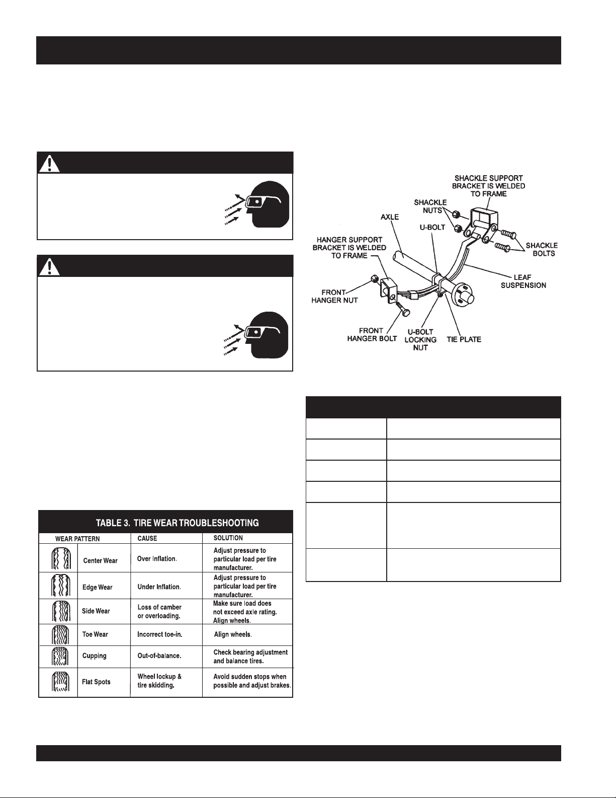
The
(Figure 4) should be visually inspected every 6,000 miles for
signs of excessive wear, elongation of bolt holes, and
loosening of fasteners. Replace all damaged parts
(suspension) immediately. Torqued suspension components
CAUTION - EYESIGHT HAZARD
ALWAYS
wear safety glasses when
as detailed in Table 4.
removing or installing force fitted parts.
Failure to comply may result in serious
injury.
CAUTION - REPAIRING TRAILER WHEELS
DO NOT attempt to repair or modify a wheel. DO NOT
install in inner tube to correct a leak through the rim. If the
rim is cracked, the air pressure in the inner
tube may cause pieces of the rim to
explode (break off) with great force and
cause serious eye or bodily injury.
leaf suspension
Figure 4. Major Suspension Components
springs and associated components
Tire Wear/Inflation
Tire inflation pressure is the most important factor in tire life.
Pressure should be checked cold before operation DO NOT
bleed air from tires when they are
hot!
. Check inflation
pressure weekly during use to insure the maximum tire life
and tread wear.
Table 3 (Tire Wear Troubleshooting) will help pinpoint the
causes and solutions of tire wear problems.
SHACKLE BOLT
SPRING EYE BOLT
SHOULDER TYPE
SHACKLE BOLT
metI ).sbL-.tF(euqroT
TLOB-U"8/353-XAM03-NIM
TLOB-U"61/706-XAM54-NIM
TLOB-U"2/106-XAM54-NIM
SNUG FIT ONLY
LOCKING NUTS OR COTTER PINS ARE PROVIDED
TO RETAIN NUT
stnemeriuqeReuqroTnoisnepsuS.4elbaT
.
PARTS MUST ROTATE FREELY
-
BOLT ASSEMBLY
.
05-XAM03-NIM
.
PAGE 20 —SDW-225SS WELDER/GENERATOR— OPERATION & PARTS MANUAL — REV. # 2 (10/07/05)
Page 21
SDW-225SS — TRAILER-10 MAINTENANCE
Lug Nut Torque Requirements
It is extremely important to apply and maintain proper wheel
mounting torque on the trailer. Be sure to use only the
fasteners matched to the cone angle of the wheel. Proper
procedure for attachment of the wheels is as follows:
1. Start all wheel lug nuts by hand.
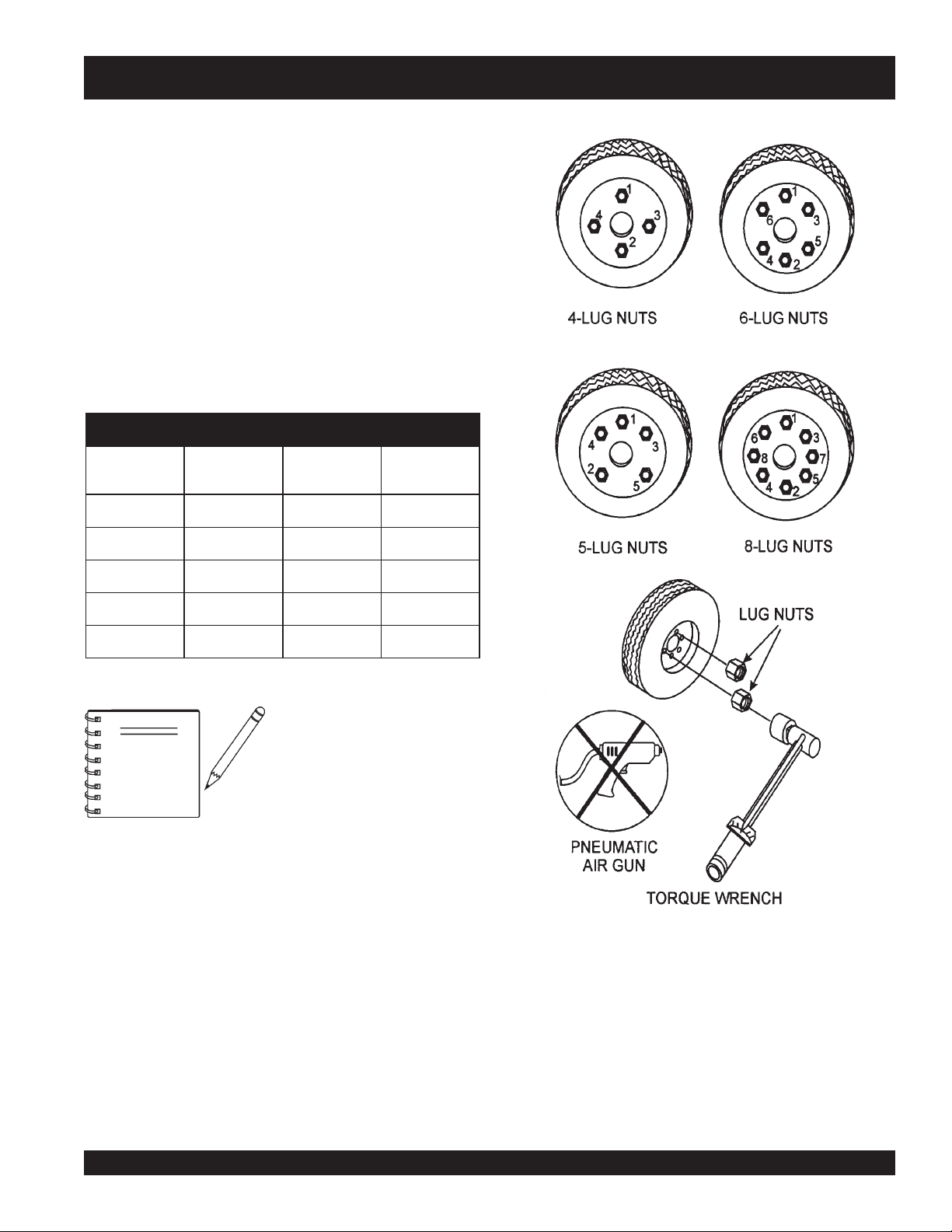
2. Torque all lug nuts in sequence (see Figure 5). DO NOT
torque the wheel lug nuts all the way down. Tighten each
lug nut in 3 separate passes as defined by Table 5.
3. After first road use, re-torque all lug nuts in sequence.
Check all wheel lug nuts periodically.
stnemeriuqeReuqroTeriT.5elbaT
eziSleehWssaPtsriF
SBL-TF
"2152-0204-5356-05
"315
"4152-0206-05021-09
"5152-0206-05021-09
"6152-0206-05021-09
NOTE
2-0204-5356-05
NEVER
ssaPdnoceS
SBL-TF
use an pneumatic air
gun to tighten wheel lug nuts.
ssaPdrihT
SBL-TF
Figure 5. Wheel Lug Nuts
Tightening Sequence
SDW-225SS WELDER/GENERATOR — OPERATION & PARTS MANUAL — REV. #2 (10/07/05) — PAGE 21
Page 22
SDW-225SS — TRAILER-10 MAINTENANCE
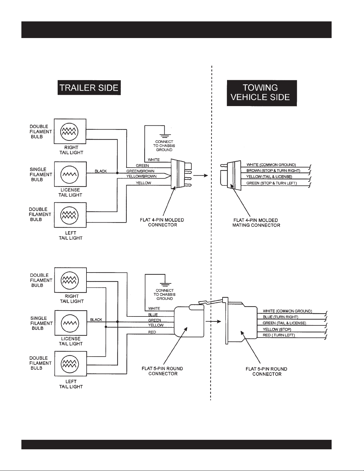
Figure 6. Trailer/Towing Vehicle Wiring Diagram
PAGE 22 —SDW-225SS WELDER/GENERATOR— OPERATION & PARTS MANUAL — REV. # 2 (10/07/05)
Page 23
SDW-225SS — TRAILER-10 MAINTENANCE
Towing Safety Precautions
CAUTIONCAUTION
CAUTION
CAUTIONCAUTION
Check with your local county or state towing safety
regulations before towing your generator.
To reduce the possibility of an accident while transporting
the generator on public roads, always make sure the trailer
(Figure 7) that supports the generator and the towing vehicle
are in good operating condition and both units are
mechanically sound.
The following list of suggestions should be used when towing
your generator:
■
Make sure the hitch and coupling of the towing vehicle
are rated equal to, or greater than the trailer "gross vehicle
weight rating" (GVWR).
■
ALWAYS inspect the hitch and coupling for wear. NEVER
tow a trailer with defective hitches, couplings, chains
etc.
■
Check the tire air pressure on both towing vehicle and
trailer. Also check the tire tread wear on both vehicles.
■
ALWAYS make sure the trailer is equipped with a "Safety
Chain".
■
ALWAYS attach trailer’s safety chain to bumper of towing
vehicle.
■
ALWAYS make sure the vehicle and trailer directional,
backup, brake, and trailer lights are connected and
working properly.
■
The maximum speed for highway towing is 55 MPH
unless posted otherwise. Recommended off-road towing
is not to exceed 15 MPH or less depending on type of
terrain. Refer to state or local towing regulations.
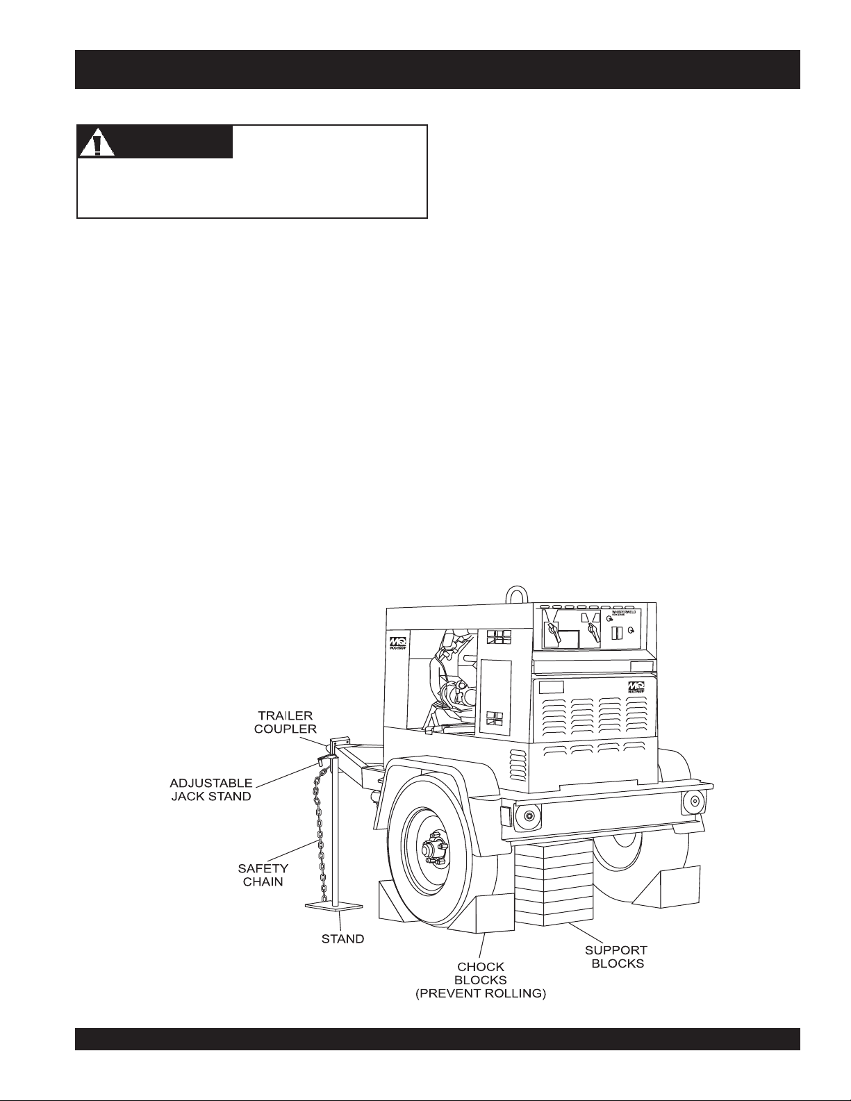
■
Place
rolling, while parked.
■
Place
prevent tipping, while parked.
■
Insert locking pin to lock wheel stand in place, while
parked. Use the trailer’s adjustable jack stand to adjust
the height of the trailer.
■
Avoid sudden stops and starts. This can cause skidding,
or jackknifing. Smooth, gradual starts and stops will
improve gas mileage of towing vehicle.
■
Avoid sharp turns to prevent rolling.
■
Remove or fold up wheel stand when transporting.
■
DO NOT transport generator with fuel in tank.
chocked blocks
support blocks
underneath wheel to prevent
underneath the trailer’s bumper to
Figure 7. Generator with Trailer
SDW-225SS WELDER/GENERATOR — OPERATION & PARTS MANUAL — REV. #2 (10/07/05) — PAGE 23
Page 24
SDW-225SS — WKT225A WHEEL KIT ASSEMBLY
The SDW-225SS welder/generator can be mounted on a
WKT225A Wheel Kit. .
Below are assembly Instructions for the WKT225 Wheek Kit.
Tools:
■■
■
Flashlight
■■
■■
■
Ratchet Set with 3/4", 9/16" sockets
■■
■■
■
Adjustable Wrench or 3/4", 9/16", 10mm open
■■
end wrenches
■■
■
Lifting Device of adequate capacity
■■
Procedure:
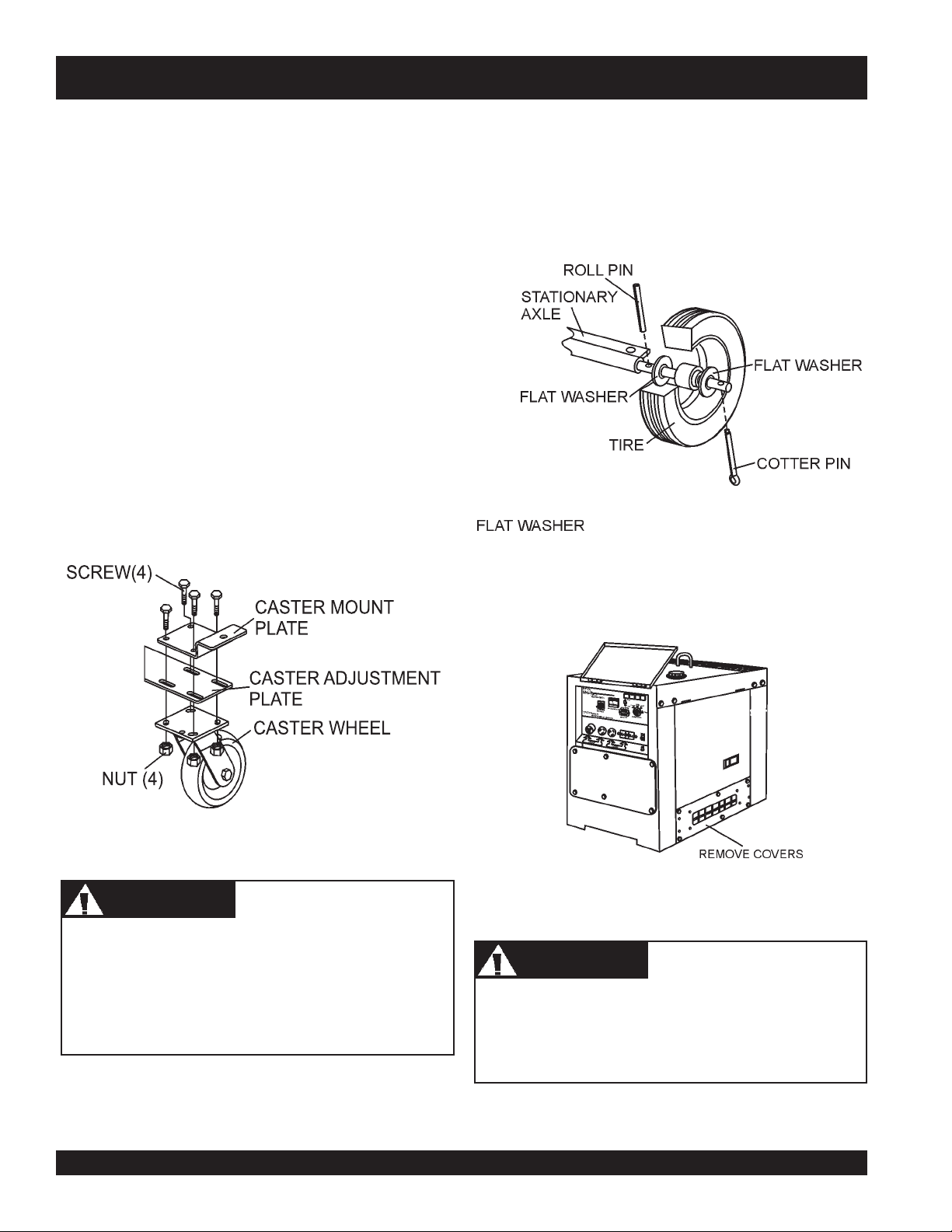
1. Assemble the Caster wheels (Figure 8) - Place the Caster
mount plate on the adjustment plate so the bolt holes
line up. Insert screws through the holes in the two plates
and push the caster wheel onto the screws. Loosely
secure the caster wheel to the adjustment plate using
the provided nuts to allow for adjustment when attaching
the caster wheels to the cabinet. Repeat for the other
side of the caster wheel assembly.
2. Assemble the stationary axle (Figure 9) - Push the roll
pin through the inner axle hole. Slide a flat washer onto
the axle shaft, then put the wheel on the axle. Push the
wheel flat against the washer and roll pin and slide a flat
washer against the wheel. Then insert the cotter pin
through the outer axle hole to secure the wheel on the
axle.
Figure 9. Stationary Axle Assembly
3. Remove side covers to provide access to the interior of
the cabinet. (Figure 10).
Figure 8. Caster Wheel Assembly
WARNINGWARNING
WARNING
WARNINGWARNING
DO NOT attempt to manually lift your generator/welder.
Use a lifting device that is rated to handle the full weight
of the equipment. DO NOT stand under the machine
while it is suspended in air.
Two people might be required to perform this installation
procedure safely. One person should support the axle
for another person to prevent the axle from dropping.
Figure 10. Removing Access Covers
CAUTICAUTI
CAUTION
CAUTICAUTI
PAGE 24 —SDW-225SS WELDER/GENERATOR— OPERATION & PARTS MANUAL — REV. # 2 (10/07/05)
Page 25
SDW-225SS — WKT225A WHEEL KIT ASSEMBLY
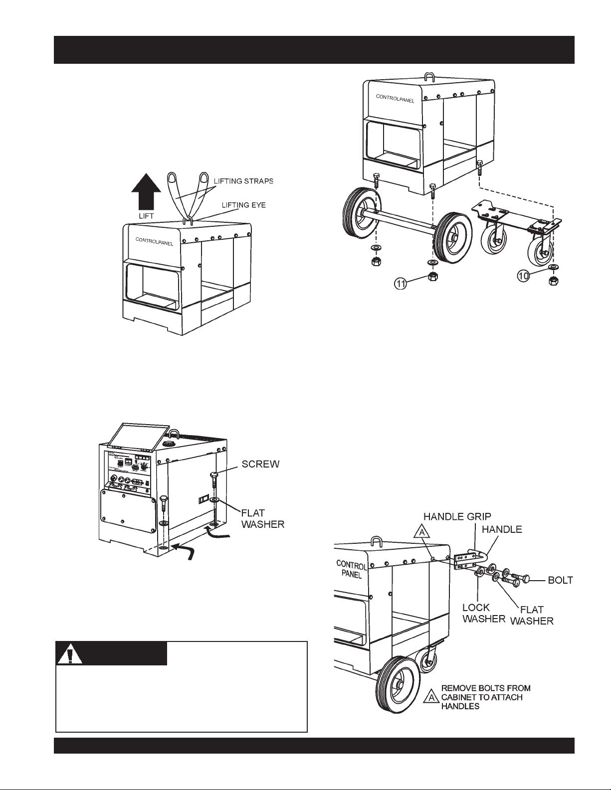
4. Insert a lifting strap through the lifting eye on top of the
machine and raise the generator/welder off the ground
using a lifting device of adequate capacity (Figure 11).
The generator/welder can be suspended in air while
installing the wheel kit or can be set down on an object
which can support the weight of the machine. Ensure the
bottom of the cabinet has enough clearance to install the
wheel kit.
7. Center the caster wheel assembly underneath the
Figure 11. Lifting Equipment
5. Locate the four bolt holes on the underside of the cabinet
near the front and rear of the machine. Reach into the
cabinet and place a bolt and washer through the cabinet
floor through each hole (Figure 12). A flashlight might be
necessary to find the bolt holes in the cabinet floor.
machine. Lift the caster wheels up so the bolts in the
cabinet floor pass through the bolt holes on the caster
wheel frame. Place a washer on the bolt under the castor
wheel frame and secure the castor wheels to the cabinet
with a nut (Figure 13).
8. Lower the machine onto the ground and remove the lifting
strap from the lifting eye. The machine should roll freely.
Figure 13. Securing Stationary Axle and
Caster Wheel Assembly to Cabinet
9. Near the top of the cabinet on the rear(control panel side)
of the machine, remove the two bolts from the cabinet
wall. Attach the handle to the cabinet wall by inserting a
bolt, lock washer, and flat washer through the bottom
two bolt holes on the handle into the cabinet (Figure 14).
Repeat on the other side of the cabinet.
Figure 12. Inserting Bolts/Washers
6. With the stationary axle facing front, lift the axle up so
the bolts in the cabinet floor pass through the bolt holes
on the axle. Place a washer on the bolt under the axle
and secure the axle to the cabinet with a nut (Figure 13).
CAUTICAUTI
CAUTION
CAUTICAUTI
Lock the caster wheels in place with the attached brake
lever when the generator/welder is not being moved to
prevent the machine from unintentional rolling while in
use.
Figure 14. Attaching Handles to Cabinet
SDW-225SS WELDER/GENERATOR — OPERATION & PARTS MANUAL — REV. #2 (10/07/05) — PAGE 25
Page 26
SDW-225SS — INSTALLATION
Outdoor Installation
Install the generator in a location where it will not be exposed
to rain or sunshine. Make sure that the welder/generator is
on secure level ground so that it cannot slide or shift around.
Also install the generator in a manner so that the exhaust
will not be discharged in the direction of nearby homes.
The installation site must be relatively free from moisture
and dust. All electrical equipment should be protected from
excessive moisture. Failure to do will result in deterioration
of the insulation and will result in short circuits and grounding.
Foreign materials such as dust, sand, lint and abrasive
materials have a tendency to cause excessive wear, not
only to the engine parts, but also to the alternator parts.
CAUTICAUTI
CAUTION
CAUTICAUTI
Pay close attention to ventilation when operating the
generator inside tunnels and caves. The engine exhaust
contains noxious elements.
Indoor Installation
Exhaust gases from diesel engines are extremely poisonous.
Whenever an engine is installed indoors the exhaust fumes
must be vented to the outside.
The engine should be installed at least two feet from any
outside wall. Using an exhaust pipe which is too long or too
small can cause excessive back pressure which will cause
the engine to heat excessively and possibly burn the valves.
Eliminate the danger of deadly carbon monoxide gas.
Remember that exhaust fumes from any diesel engine are
very poisonous if discharged in a closed room, but harmless
if allowed to mix with the outside air. If the generator is
installed indoors, you must make provisions for venting the
engine exhaust to the outside of the building.
An electric shock is apt to happen when generators are
used. Pay close attention to handling when operating
generator and always use rubber boots and gloves to
insulate the body from a short circuit.
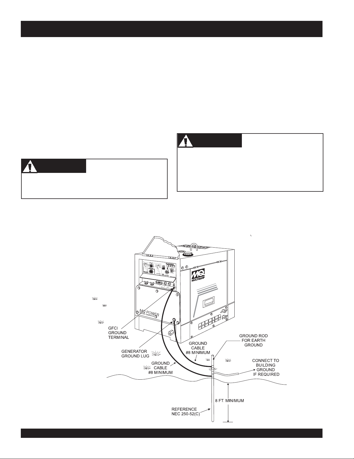
Connecting the Ground
The generator ground lug and the GFCI ground terminal should
always be used to connect the generator to a suitable ground.
The ground cable should be #8 size wire minimum. See Figure 15.
CAUTICAUTI
CAUTION
CAUTICAUTI
Figure 15. Generator Grounding
PAGE 26 —SDW-225SS WELDER/GENERATOR— OPERATION & PARTS MANUAL — REV. # 2 (10/07/05)
Page 27

SDW-225SS — PRE-SETUP
General Inspection Prior to Operation
The SDW-225SS utilizes a generator that has been thoroughly
inspected and accepted prior to shipment from the factory.
However, be sure to check for damaged parts or components,
or loose nuts and bolts, which could have occurred in transit.
Circuit Breakers
To protect the welder/generator from an overload,
amp,
main
circuit breaker is provided. In addition a single
pole, 20 amp breaker is provided for the G.F.C.I. receptacle.
Make sure to switch both circuit breakers to the "OFF"
position prior to starting the engine.
a 2-pole, 25
Extension Cable
When electric power is to be provided to various tools or
loads at some distance from the generator, extension cords
are normally used. Cables should be sized to allow for
distance in length and amperage so that the voltage drop
between the generator and point of use (load) is held to a
minimum. Use the cable selection chart (Table 6) as a guide
for selecting proper cable size.
sttaWnIdaoLhtgneLelbaCelbawollAmumixaM
nitnerruC
serepmA
021tA
stloV
042tA
stloV
eriW01#eriW21#eriW41#eriW61#
)noitarepOesahPelgniS,zH06(noitceleSelbaC.6elbaT
5.2003006.tf0001.tf006.tf573.tf052
50060021.tf005.tf003.tf002.tf521
5.
70090081.tf053.tf002.tf521.tf001
0100210042.tf052.tf051.tf001
5100810063.tf051.tf001.tf56
0200420084.tf521.tf57.tf05
0300630027.t
f57.tf05.tf53
.egatlovwolmorftlusernacegamadtnempiuqE:NOITUAC
SDW-225SS WELDER/GENERATOR — OPERATION & PARTS MANUAL — REV. #2 (10/07/05) — PAGE 27
Page 28
SDW-225SS — PRE-SETUP
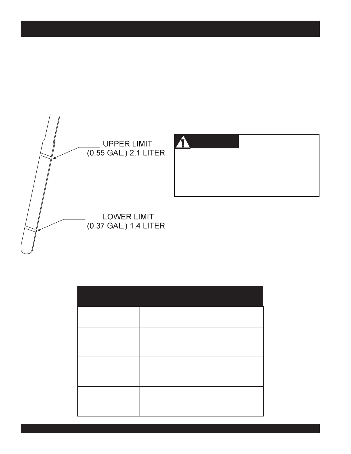
Lubrication Oil
Fill the engine crankcase with lubricating oil through the filler
hole, but do not overfill. Make sure the generator is level.
With the dipstick inserted all the way, but without being
screwED into the filler hole, verify that the oil level is
maintained between the two notches (Figure 16) on the
dipstick. See Table 3 for proper selection of engine oil.
Fuel
Fill the fuel tank with clean and fresh diesel fuel. Do not fill
the tank beyond capacity.
Pay attention to the fuel tank capacity when replenishing
fuel. Refer to the fuel tank capacity listed on page 11
Specification Table 1.
The fuel tank cap must be closed tightly after fillin
fuel in a safety container. If the container does not have a
spout, use a funnel.
Never fill the fuel tank while the engine is running or in
the dark. Diesel fuel spillage on a hot engine can cause
a fire or explosion. If diesel fuel spillage occurs, wipe
up the spilled diesel fuel completely to prevent fire
hazards.
Coolant
CAUTICAUTI
CAUTION
CAUTICAUTI
g. Handle
Figure 16. Engine Oil Dipstick
egnaRerutarepmeTliOepyT
F°77evobA
)C°52(
F°77~F°23
)C°52~C°0(
Use only potable tap water. If hard water or water with many
impurities is used, the inside of the engine and radiator may
become coated with deposits and cooling efficiency will be
reduced.
An anticorrosion additive added to the water will help prevent
deposits and corrosion in the cooling system. See the engine
manual for further details.
liOrotoMdednemmoceR.7elbaT
ro03EAS
03-W01EAS
04-W01EAS
ro02EAS
03-W01EAS
04-W01EAS
ro01EAS
)C°0(F°23woleB
PAGE 28 —SDW-225SS WELDER/GENERATOR— OPERATION & PARTS MANUAL — REV. # 2 (10/07/05)
03-W01EAS
04-W01EAS
Page 29
SDW-225SS — PRE-SETUP
CAUTICAUTI
CAUTION
CAUTICAUTI
When adding coolant or anti-freeze to the radiator, do
not remove the radiator cap until the unit has completely
cooled.
Day-to-day addition of coolant or anti-freeze is done from
the reserve tank. See Table 8. for engine, radiator and reserve
tank coolant capacities. Make sure that the coolant level in
the reserve tank is always between the "H" and the "L"
markings.
yticapaCtnalooC.8elbaT
rotaidaRdnaenignE.laG66.0
knaTevreseR.laG72.0
Day-to-day addition of coolant is done from the
Operation in Freezing Weather
When operating in freezing weather, be certain that the proper
amount of antifreeze has been added.See Table 9. for antifreeze operating temperatures.
Cleaning the Radiator
The radiator may overheat if the fins become overloaded
with dust or debris. Periodically clean the radiator fins with
compressed air. Cleaning inside the machine is dangerous,
so clean only with the engine turned off.
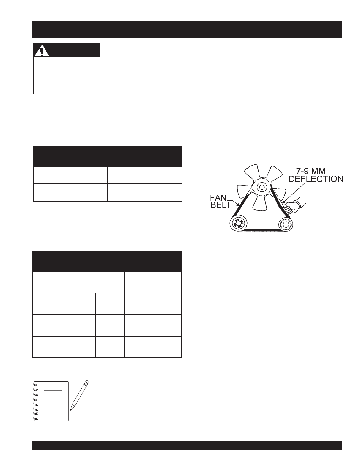
Fan Belt Tension
A slack fan belt may contribute to overheating, or to
insufficient charging of the battery. Inspect and adjust it in
accordance with the KUBOTA engine manual.
The fan belt tension is proper if the fan belt (Figure17) bends
7 to 9 mm (0.28- to 0.35 in.) when depressed with the thumb
as shown in Figure 16 below.
Figure 17. Fan Belt Tension
tnioPgnizeerFtnioPgnilioB
%loV
ezeerF-itnA
C°F°C°F°
0442-21-601222
0573-43-801622
When the anti-freeze is
NOTE
mixed with water, the antifreeze mixing ratio must
be less than 50%.
Air Cleaner
serutarepmeTgnitarepOezeerF-itnA.9elbaT
Periodic cleaning/replacement is necessary. Inspect it in
accordance with the engine manual.
Battery
This unit is of negative ground. DO NOT connect in reverse.
Always maintain battery fluid level between the specified
marks. Battery life will be shortened, if the fluid level is not
properly maintained. Add only distilled water when
replenishment is necessary.
The battery is sufficiently charged if the specific gravity of
the battery fluid is 1.28 (at 68° F). If the specific gravity
should fall to 1.245 or lower, it indicates that the battery is
dead and needs to be recharged or replaced.
Check to see whether the battery cables are loose. Poor
contact may result in poor starting or malfunctions, always
keep the terminals firmly tightened. Coating the terminals
with a thin film of grease will help to inhibit corrosion.
The battery gradually deteriorates over time. The actual life
span will vary according to operating conditions, but generally
a battery two years or older should be replaced.
SDW-225SS WELDER/GENERATOR — OPERATION & PARTS MANUAL — REV. #2 (10/07/05) — PAGE 29
Page 30

SDW-225SS — INSTRUMENTATION
CAUTICAUTI
CAUTION
CAUTICAUTI
When using a combination of dual receptacles, total load
should not exceed the rated capacity of the generator
set.
Power Outlets
The generator has the following single-phase 60 Hz, 120/
240 volt receptacles.
zz
Single Phase
z
zz
One Duplex NEMA (GFCI) 5-20R (120V, 20 Amp)
One Twist Lock NEMA L14-30R (120/240V, 30 Amp)
One Twist Lock NEMA L5-30R (120V, 30 Amp)
Main Circuit Breaker (2-Pole)
This 2-pole, 25 amp breaker protects the generator from
short circuiting or overloading from the 60 Hz single-phase
load.
GFCI Protection Breaker (Single-Pole)
This single-pole, 20 amp breaker protects the GFCI
receptacle from short circuiting or overloading.
Warning Indicator Lights
The generator has the following warning indicator lights:
Oil Pressure Light
If the oil pressure drops suddenly, the oil pressure light will
go on, and the generator will shut down.
Charge Light
The charge light will go on when the battery fails to charge,
and the generator will shut down.
Water Temperature Light
The water temperature light will go on if the temperature
rises to an abnormally high level, and the generator will shut
down.
I
dle Control Switch
The generator is provided with an automatic idle control device
for noise suppression and reduced fuel consumption. The
automatic idle control automatically engages under a no-load
condition. With the automatic idle control switched to "ON", the
engine revolutions will automatically drop to about 2600 rpm
(low-speed operation) within 3 seconds after the load stops.
When the operation is resumed, the engine speed is automatically
increased to about 3600 rpm (high speed operation) as soon as
the load is connected.
Fuel Gauge
The fuel gauge is located on top of the generator's enclosure
and allows easy monitoring of the fuel level.
GFCI Receptacle
Before connecting a load to the generator's GFCI receptacle,
push
the "Test Button" on the front of receptacle before
connecting the load, to confirm that the receptacle is
functioning correctly.
PAGE 30 —SDW-225SS WELDER/GENERATOR— OPERATION & PARTS MANUAL — REV. # 2 (10/07/05)
Page 31

SDW-225SS — LOAD APPLICATION
Single Phase Load
Always be sure to check the nameplate on the generator
and equipment to insure the wattage, amperage and
frequency requirements are satisfactorily supplied by the
generator for operating the equipment.
Generally, the wattage listed on the nameplate of the
equipment is its rated output. Equipment may require
130-150% more wattage than the rating on the nameplate,
as the wattage is influenced by the efficiency, power factor
and starting system of the equipment.
If wattage is not given on the
NOTE
The power factor of this welder/generator is 1.0. See Table
10 below when connecting loads.
equipment's name plate, approximate
wattage may be determined by
multiplying nameplate voltage by the
nameplate amperage.
WATTS = VOLTAGE x AMPERAGE
An inadequate size connecting cable which cannot carry
the required load can cause a voltage drop which can burn
out the appliance or tool and overheat the cable.
The idle control is operated at minimum load capacity of
100W. If the load capacity is less than 100W, throw the idle
control switch to the OFF position.
Before connecting this generator to any building’s electrical
system, a licensed electrician must install an isolation
(transfer) switch. Serious injury or death may result without
this transfer switch.
CAUTICAUTI
CAUTION
CAUTICAUTI
Motors and motor-driven equipment draw much greater
current for starting than during operation.
CAUTICAUTI
CAUTION
CAUTICAUTI
daoLyBrotcaFrewoP.01elbaT
daoLfOepyTrotcaFrewoP
srotomnoitcudniesahp-elgniS57.0-4.0
aehcirtcelE0.1
z
When connecting a resistance load such as an
incandescent lamp or electric heater, a capacity of up
to the generator's rated output (kW) can be used.
z
When connecting a fluorescent or mercury lamp, a
capacity of up to the generator's rated output (kW)
multiplied by 0.6 can be used.
z
When connecting an electric drill or other power tools,
pay close attention to the required starting current
z
When connecting ordinary power tools, a capacity of up
to the generator’s rated output (kW) multiplied by 0.8
can be used.
spmaltnecsednacni,sret
spmalyrucem,spmaltnecseroulF9.0-4.0
tnempiuqenoitacinummoc,secivedcinortcelE0.1
Before connecting this generator to any building’s
electrical system, a licensed electrician must install an
isolation (transfer) switch. Serious injury or death may
result without this transfer switch.
SDW-225SS WELDER/GENERATOR — OPERATION & PARTS MANUAL — REV. #2 (10/07/05) — PAGE 31
Page 32

SDW-225SS— WELDER OPERATING INSTRUCTIONS
Welding Cables
Connect the welding cables (Figure 18) to the welder's output
terminals located on the control panel. The output terminals
NOTE
have (+) and (-) polarities. Select the appropriate polarities
according to the application (see Table 11).
Figure 18. Welding Cable Connection
(Correct)
ALWAYS attach terminal connectors
at the end of each cable. NEVER
connect exposed or frayed wires
(Figure 19) directly to the terminals.
Exposed wiring may cause shocks
or di-electric breakdown from poor
contact.
Figure 19. Welding Cable Connection
Welding Polarity
Polarity indicates the direction of the current flow in a circuit.
Since DC current moves in only one direction, polarity is
important because the flow of current must be changed
depending on the application. By changing the polarity, the
greatest amount of heat can be concentrated where it is most
needed. With straight polarity (electrode negative) more heat is
directed to the workplace. When using reverse polarity (electrode
positive) more of the heat generated is directed to the electrode.
See Figure 20.
(Incorrect)
Figure 20. Welding Polarity
PAGE 32 —SDW-225SS WELDER/GENERATOR— OPERATION & PARTS MANUAL — REV. # 2 (10/07/05)
Page 33

SDW-225SS— WELDER OPERATING INSTRUCTIONS
CAUTICAUTI
CAUTION
CAUTICAUTI
NEVER
welding operation. When switching a selector switch,
fully rotate it to the right or left position.
switch the CV/CC
Selector Switch
during any
NOTE
When the CV/CC
is in the CC position, the
Control
function is inoperative.
Selector Switch
Voltage
1. Turn the CV/CC
position, and adjust voltage using the
knob.
Figure 21. Welding Voltage Adjustment
NOTE
Selector Switch
When the CV/CC
in the CV position, the
Control
Selector Switch
inoperative.
(Figure 21) to the
, and
CV
Voltage Control
Selector Switch
Current Range
functions are
is
Current
3. Set the CC
desired position (Low/High).
4. Adjust current output, by setting
to desired current output.
NOTE
Auxiliary AC Power
The Auxiliary AC power in most cases will not be affected
by the CV/CC Selector Switch or any controls (Figure 23)
on the front panel, and will supply a stable constant AC
voltage except when the welding mode is activated.
Current Range Selector Switch
Current Control
When using the
knob to adjust the current output, the
outer scale is for the high range, and
the inner scale is for the low range.
Current Control
to the
knob
2. Turn the CV/CC
position.
Figure 22. Welding Current Adjustment
SDW-225SS WELDER/GENERATOR — OPERATION & PARTS MANUAL — REV. #2 (10/07/05) — PAGE 33
Selector Switch
(Figure 22) to the
CC
Figure 23. Auxilliary AC Power
When welding, remember that the
NOTE
output of the AC AUXILIARY POWER
is affected by the welding operation.
See next page for generator output
voltage conditions when welding.
Page 34

SDW-225SS— WELDER OPERATING INSTRUCTIONS
Welding and Auxiliary Outputs.
The welding and auxiliary outputs can be used simultaneously,
subject to all of the following conditions:
z
CC/CV Selector Switch is in the CC mode.
z
CC Current Range Selector is in the low mode.
z
Current Control is in the MAX position.
Duty Cycle
The welder is rated at 100% duty cycle at 200 amps.
However the duty cycle depends upon the welding
current. Select the appropriate duty cycle from Table 12
to prevent overload.
NOTE
The 250 amp, 60% duty cycle
referenced in Table 12 is for CV
welding ONLY.
Quality Welding Check Points
Adherence to the following rules will ensure quality welds.
■
Use only high-quality welding machines, electrodes and
welding accessories.
■
Know the base material you are working on.
■
Select the proper welding process to give the highest
quality welds on the base material to be used.
■
Select the proper welding procedure to meet the service
requirement.
■
Select the correct electrode for the job.
■
When preheating is specified or required, make sure the
temperature requirements are met. In any case, do not
weld on material below 32 °F without first preheating.
■
Clean the base metal of all slag, paint, grease, oil,
moisture and any other foreign materials.
■
Remove weld slag and thoroughly clean each bead prior
to making the next bead or pass.
■
Do not weld over cracks or porous tack welds. Defective
tack welds should be removed prior to welding.
elcyCytuD.21elbaT
)%(elcyCytuD0010806
)spmA(tnerruCsselro002522052
■
Be particularly alert to obtain root fusion on the first pass
of fillet and groove welds.
■
When root gaps of groove welds are excessive, build up
one side of the joint prior to welding the pieces together.
■
When the root gap is excessive in fillet welding, be sure
to increase the size of the fillet weld to the amount of the
root gap in order to maintain the strength requirement.
In some cases it is advantageous to make a groove
weld in order to avoid extremely large fillets.
■
Inspect your work and immediately replace any defective
weld.
■
Observe the size requirement for each weld to ensure
you meet or slightly exceed the specified size.
■
Make sure the finished appearance of the weld is smooth
and that all overlaps and undercuts are repaired properly.
The strength of a weld should not be judged merely by
its external appearance.
PAGE 34 —SDW-225SS WELDER/GENERATOR— OPERATION & PARTS MANUAL — REV. # 2 (10/07/05)
Page 35

SDW-225SS— WELDER OPERATING INSTRUCTIONS
Welding Helmet Lens Shade Number
The shade number pertains to the lightness or darkness of the
lens in the welding helmet. Lens number range from 2 to 14
where 2 would be the lightest lens and 14 would be the darkest
lens. See Table 13 for the correct shade number for different
types of welding.
REBMUNEDAHSGNIDLEW.31elbaT
NOITAREPOGNIDLEWFOEPYT
GNIREDLOS2
GNIZARBHCROT4ro3
)hcni1otpU(GNITTUCNEGYXO4ro3
)sehcni6ot1(GNITTUCNEGYXO5ro4
)revodnasehcni6(GNITTUCNEGYXO6ro5
)hcni8/1otpU(GNIDLEWSAG5ro4
/1(GNIDLEWSAG6ro5
)hcni2/1othcni8
)revodnahcni2/1(GNIDLEWSAG8ro6
GNIDLEWCRA-LATEMDEDLEIHS
hcni23/5,8/1,23/3,61/1
-noN(GNIDLEWCRA-NETSGNUTSAG
)suorreF
)suorreF-noN(GNIDLEWCRA-LATEMSAG
sedortcelehcni23/5,8/1,23/3,61/1
01
11
SNELTEMLEHGNIDLEW
REBMUNEDAHS
(GNIDLEWCRA-NETSGNUTSAG
sedortcelehcni4/1,23/7,61/3
sedortcelehcni,8/3,61/5
YHCIMOTA41ot01
GNIDLEWCRA-NOBRAC41
SDW-225SS WELDER/GENERATOR — OPERATION & PARTS MANUAL — REV. #2 (10/07/05) — PAGE 35
)suorreF
)suorreF(GNIDLEWCRA-LATEMSAG
sedortcelehcni23/5,8/1,23/3,61/1
GNIDLEWCRA-LATEMGNIDLEIHS
GNIDLEWCRA-LATEMGNIDLEIHS
GNIDLEWNEGORD
21
21
41
Page 36

SDW-225SS — ENGINE OPERATING INSTRUCTIONS
4. Turn the key to the HEAT position. When the preheat
WARNINGWARNING
WARNING
WARNINGWARNING
The engine's exhaust contains harmful emissions.
ALWAYS
tunnels, excavations or buildings. Direct exhaust away
from nearby personnel.
Before Starting
1. Be sure to disconnect the electrical load and switch the
main circuit breaker to the “OFF” position prior to starting
the engine.
2. Never start the engine with the main circuit breaker “ON”.
3. Check the engine oil level prior to starting the engine.
Make sure the generator is level. The oil level must be
maintained between two notches on the dipstick.
4. When there is not enough engine oil, fill the crankcase
with high grade motor oil. Engine oil should be
MIL-L-2104C or have properties of API classification
CD grades or higher. Change the type of engine oil
according to the ambient temperature. (See Table 7 on
page 28).
5. Check the coolant level in the radiator and subtank.
Replenish with antifreeze as necessary. Always maintain
the coolant level between the FULL and LOW markings
on the coolant container. Be sure that the radiator cap is
fastened securely.
6. Check the fuel level on the fuel gauge. When fuel is low,
fill the fuel tank with clean fresh DIESEL FUEL..
ventilate the exhaust when operating inside
light is off, turn the key to the ”START” position to start
the engine. As soon as the engine starts, release the
key. The key will automatically return to the “RUN”
position.
5. During winter or when the surrounding air temperature is
cold, in situations where a load start is required, turn
the key to the “HEAT” position, you must wait until the
preheat light goes off.
6. If the engine does not start within 10 seconds after the
key is turned to the “START” position, wait for about 30
seconds and repeat the procedure as described in step 4
above.
NEVER turn the key to the “
the engine is running.
7. When the engine starts, the Oil Pressure Light and
Charge Light should turn off. If these lights stay on,
immediately stop the engine and check the system and
wiring (refer to the Engine Operation Manual).
8. Let the engine idle for five minutes with the Automatic
Idle Control switch in the “ON” position.
9. Check the engine for abnormal vibrations, noises and
oil leakage.
CAUTICAUTI
CAUTION
CAUTICAUTI
START
” position while
10. Turn the
CAUTICAUTI
CAUTION
CAUTICAUTI
If diesel fuel spillage occurs, completely wipe up the spilled
diesel fuel.
Starting
1. Turn the fuel cock lever to the “ON” position.
2. Always operate the generator with the doors in the closed
position. Operation with the doors open may cause
insufficient cooling to the unit and damage may result.
3. Insert the key into the starter switch and turn it to the
“RUN” position. Check to see that the Oil Pressure and
Charge Lights on the "Warning Lamp Unit " are lit. If
either light is not lit, check the system and wiring (refer
to the Engine Operation Manual).
PAGE 36 —SDW-225SS WELDER/GENERATOR— OPERATION & PARTS MANUAL — REV. # 2 (10/07/05)
or “ON” for full engine operation.
Shutdown
1. Remove the load from the generator, then place both
the main and GFCI circuit breakers to the OFF position.
2. Listen for the engine speed to drop. Run at low speed
for 3-5 minutes.
3. Stop the engine by turning the key to “STOP” position
and remove the key. Turn the fuel cock lever to the
“OFF” position.
Automatic Idle Control Switch
to either “OFF”
Page 37

SDW-225SS — MAINTENANCE
General Inspection
At least daily or prior to each use, the generator should be
cleaned and inspected for deficiencies. Check for loose,
missing or damaged nuts, bolts or other fasteners. Check
for fuel or oil leaks. Also check the radiator coolant level.
Engine Side:
For a more detail engine maintenance schedule refer to the
KUBOTA Engine Shop and Operator's Manuals.
Air Cleaner
Every 100 hours: The air cleaner employed on the KUBOTA
engine Model Z482-E is a dry type. NEVER apply oil to it. If
generator is used in severe dusty areas service air cleaner
element more frequently.
1. Release the air cleaner retaining clamps (Figure 24) and
remove the air cleaner element.
2. Wipe the inside of the air cleaner with a damp cloth and
remove all dust and debris that may have accumulated
inside air cleaner body.
3. Use compressed air to clean air filter element. Blow
compressed air from the inside while turning the element.
Oil Change
Every 100 hours: Change the engine oil after the first 50
hours of operation. Always check the crankcase oil level
prior to each use, or when the fuel tank is filled. Insufficient
oil may cause severe damage to the engine. Make sure the
generator is level when checking the oil level. The oil level
must be between the two notches on the dipstick as shown
in Figure 15.
Oil Cartridge
Every 200 hours: Replace the engine oil filter cartridge
after every 200 hours of operation.
Fuel Addition
Add diesel fuel (the grade may vary according to season
and locations). Always pour through the mesh filter.
Removing Water from the Tank
After prolonged use, water and other impurities accumulate
in the bottom of the tank. Occasionally remove the drain
cock and drain the contents. During cold weather, the more
empty area inside the tank, the easier it is for water to
accumulate. This can be reduced by always keeping the
tank as full as possible.
CAUTICAUTI
CAUTION
CAUTICAUTI
ALWAYS keep the pressure of the compressed air
below 99 psi.
Figure 24. Air Cleaner
Cleaning the Fuel Strainer
Every 100 hours: Clean the fuel strainer if it contains dust
or water. Remove dust or water in the strainer cap. Securely
fasten the fuel strainer cap so that fuel will not leak. Check
the fuel strainer every 100 hours of operation or once a month.
Air Removal
If air enters the fuel system of a diesel engine, starting
becomes impossible. After running out of fuel, or after
disassembling the fuel system, bleed the system according
to the following procedure.
To restart after running out of fuel, turn the key switch to the
“START” position for 15-30 seconds. Try again, if needed.
This unit is equipped with an automatic air bleeding system.
Service Daily
If engine is operating in very dusty and dry grass conditions.
A clogged air cleaner will result in high fuel consumption,
loss of power and excessive carbon buildup in the
combustion chamber.
SDW-225SS WELDER/GENERATOR — OPERATION & PARTS MANUAL — REV. #2 (10/07/05) — PAGE 37
Page 38

SDW-225SS — PREPARATION FOR LONG - TERM STORAGE
Generator Storage
For storage of the generator for over 30 days, the following
is required:
z
Drain the fuel tank completely.
z
Run the engine until
consumed.
z
Completely drain the oil from the crankcase and refill
with fresh oil.
z
Disconnect the
z
Clean all external parts of the generator with a cloth.
z
Cover the welder/generator and store in a clean, dry
place.
negative
all
the diesel fuel is completely
battery cable from the battery.
PAGE 38 —SDW-225SS WELDER/GENERATOR— OPERATION & PARTS MANUAL — REV. # 2 (10/07/05)
Page 39

Generator Wiring Diagram
SDW-225SS —GENERATOR WIRING DIAGRAM
SDW-225SS WELDER/GENERATOR — OPERATION & PARTS MANUAL — REV. #2 (10/07/05) — PAGE 39
Page 40

Engine Wiring Diagram
SDW-225SS — ENGINE WIRING DIAGRAM
PAGE 40 —SDW-225SS WELDER/GENERATOR— OPERATION & PARTS MANUAL — REV. # 2 (10/07/05)
Page 41

SDW-225SS — TROUBLESHOOTING (WELDER)
Practically all breakdowns can be prevented by proper
handling and maintenance inspections, but in the event of a
breakdown, please take a remedial action following the
diagnosis based on the Welder Troubleshooting (Table 13)
information shown below . If the problem cannot be remedied,
please leave the unit just as it is and consult our company's
business office or service plant.
MOTPMYS MELBORPELBISSOP NOITULOS
?deepswoL .noitces"deepswoltasniamerenignE"otrefeR
?)R(rotsiserevitcefeD .rotsiserecalpeR
s'rotarenegnitneserptonsiegatlovCA
.noitcesgnidlewronoitcesCA
CAniegatlovwoldnagnidlewrooP
.noitcesrewop
?rotorevitcefeD .rotorecalpeR
?3FesufnwolB .esufecalpeR
?rotorevitcefeD .rotorecalpeR
?deepswoL .noitces"deepswoltasniamerenignE"otrefeR
?gnidniw
?rellortnoCdleiFevitcefeD ."rellortnoCdleiF"ecalpeR
?gniriWevitcefeD .gniriwriapeR
?rellortnoCdleiFevitcefeD ."rellortnoCdleiF"ecalpeR
erutamranitiucric-trohsreyaL
GNITOOHSELBUORTREDLEW.41ELBAT
.erutamraecalpeR
?gniriwevitcefeD .gniriwriapeR
?remrofsnarttnerrucevitcefeD .3TCro2TC,1TC,remrofsnartecalpeR
?rellortnoCdleiFevitcefeD ."rellortnoCdleiF"ecalpeR
?)eR(reifitcerevitcefeD .reifitcerecalpeR
onsierehttubtublamronsirewopCA
egatlovdnatnerruC.ytilibapacgnidlew
.evitarepo-nierastnemtsujda
ebtonnacrowolootsirewopCA
.lamronsignidlewtub,desu
.noosootsegrahcsidyrettaB `?rotalugerenigneevitcefeD .rotalugerecalpeR
.elbacgnidlew
?gnidniw
?gniriwevitcefeD .gniriwriapeR
rekaerbtiucricevitcefeD .rekaerbtiucricecalpeR
?)edisCA(gnidniw
?gniriwevitcefeD .gniriwriapeR
?rellortnoCdleiFevitcefeD ."rellortnoCdleiF"ecalpeR
?)2Lro1LroLCD(rotcaerevitcefeD .rotcaerecalpeR
fossenkcihtdnahtgneletauqedanI
erutamranitiucric-trohsreyaL
?sehctiwsrotcelesevitcefeD .2Sro1SecalpeR
erutamranitiucric-trohsreyaL
.elbacgnidlewecalpeR
.erutamraecalpeR
.erutamraecalpeR
?gniriwevitcefeD .gniriwriapeR
?hctiwsnoitingievitcefeD .hctiwsnoitingiecalpeR
SDW-225SS WELDER/GENERATOR — OPERATION & PARTS MANUAL — REV. #2 (10/07/05) — PAGE 41
Page 42

SDW-225SS — TROUBLESHOOTING (ENGINE & GENERATOR)
Practically all breakdowns can be prevented by proper
handling and maintenance inspections, but in the event of a
breakdown, please take a remedial action following the
diagnosis based on the Engine and Generator Troubleshooting
(Table 14) information shown below and on the proceeding
page. If the problem cannot be remedied, please leave the
unit just as it is and consult our company's business office
or service plant.
MOTPMYS MELBORPELBISSOP NOITULOS
?yrettaBdaeD .yrettaBecalpeR
.etatortonseod
.setator
retratsdnatratsotsliafenignE
retratsdnatratsotsliafenignE
?leuFoN .leuFddA
?hctiwSretratSevitcefeD .hctiwSecalpeR
?retratSevitcefeD .retratSecalpeR
?tuOdenruB5FesuF .esuFecalpeR
`?tiucriCtaeH-erPnekorB .tiucriCtaeH-erPkcehC
?gniriWevitcefeD .gniriWkcehC
?hctiwSlortnoCeldIevitcefeD .hctiwSecalpeR
?noitisopNOnisihctiwSlortnoCeldI .noitisoPFFOothctiwSteS
GNITOOHSELBUORTROTARENEG&ENIGNE.51ELBAT
"hctiwSlortnoCeldI"stratsenignE
enignednanoitisopFFOnisi
.deepswoltasniamer
ecruos
lortnoCeldI"dnastratsenignE
enignE.noitisopFFOnisi"hctiwS
rp
ootsi
.noosoot
siegatlovondnasesirdeeps
.ecruosrewopCAnitnese
?gnidniw
lortnoCeldI"dnastratsenignE
enignE.noitisopFFOnisi"hctiwS
egatlovrewopCAdnasesirdeeps
.desuebtonnacrowol
lortnoCeldI"dnastratsenignE
enignE.noitisopFFOnisi"hctiwS
segrahcsidyrettabdnasesirdeeps
?reniartSleuFdeggolC .ecalpeRronaelC
?renaelCriAdeggolC .ecalpeRronaelC
?eciveDlortnoCeldIevitcefeD .ecalpeR
?gniriWdetcennocsiD .gniriWriapeRdnakcehC
rewoPCAnitneserPegatloVoN
?rotoRevitcefeD .rotoRecalpeR
?retemtloVevitcefeD .retemtloVecalpeR
?gniriWdetcennocsiD .gniriWriapeRdnakcehC
erutamranitiucriC-trohSreyaL
?)rotcetorP(rekaerBtiucriCevitcefeD .)rotcetorP(rekaerBtiucriCecalpeR
nIseriWnekorB,tiucriC-trohSreyaL
?gnidniWerutamrA
?rotalugeRenignEevitcefeD .rotalugeRecalpeR
?gniriWevitcefeD .gniriWecalpeRroriapeR
.)1ER(reifitceRecalpeR
.erutamrAecalpeR
.erutamrAecalpeRroriapeR
lortnoCeldI"dnastratsenignE
enignE.noitisopFFOnisi"hctiwS
smeesenignednasesirdeeps
.dedaolrevo
?rotanretlAevitcefeD .rotanretlAecalpeRroriapeR
?gniraeBrotanretlAdegamaD .sgniraeBrotanretlAecalpeR
PAGE 42 —SDW-225SS WELDER/GENERATOR— OPERATION & PARTS MANUAL — REV. # 2 (10/07/05)
Page 43

SDW-225SS — TROUBLESHOOTING (ENGINE & GENERATOR)
)DEUNITNOC(GNITOOHSELBUORTROTARENEG&ENIGNE.51ELBAT
MOTPMYS MELBORPELBISSOP NOITULOS
lortnoCeldI"dnastratsenignE
enignE.noitisopFFOnisi"hctiwS
egralsahenignednasesirdeeps
.daolrevo.snoitarbiv
?noitallatsnIenignEdaB .enignEfofonoitallatsnItaepeR
lortnoCeldI"dnastratsenignE
enignE.noitisopFFOnisi"hctiwS
sahenignednasesirdeeps
.esionlamronba
lortnoCeldI"dnastratsenignE
enignE.noitisopFFOnisi"hctiwS
hgihtasniamerdnasesirdeeps
sihctiwslortnoCeldInehwdeeps
.noitisopNOehtnidecalp
?straPenignEesooL .senthgiTroFstraPenignEllAkcehC
?rotanretlAevitcefeD .stloBgnipmalCesooLrogniraeBdegamaDrofrotanretlAkcehC
?erusolcnEevitcefeD .ssenthgiTrofstloBerusolcnEkcehC
?eciveDlortnoCeldIevitcefeD .eciveDlortnoCeldIecalpeRroriapeR
?hctiwSlortnoCeldIevitcefeD .hctiwSlortnoCeldIecalpeR
?dioneloSevitcefeD .dioneloSecalpeR
?yaleRevitcefeD .yaleRecalpeR
SDW-225SS WELDER/GENERATOR — OPERATION & PARTS MANUAL — REV. #2 (10/07/05) — PAGE 43
Page 44

SDW-225SS — TROUBLESHOOTING (ENGINE)
Practically all breakdowns can be prevented by proper
handling and maintenance inspections, but in the event of a
breakdown, please take a remedial action following the
diagnosis based on the Engine Troubleshooting (Table 15)
information shown below and on the proceeding page. If the
problem cannot be remedied, please leave the unit just as it
is and consult our company's business office or service
plant.
MOTPMYS MELBORPELBISSOP NOITULOS
?leufoN .leufhsinelpeR
?metsysleufehtniriA .metsysdeelB
?metsysleufehtniretaW .knatleufmorfretawevomeR
?deggolcepipleuF .epipleufnaelC
?deggolcretlifleuF .retlifleufegnahcronaelC
foytisocsivhgihylevissecxE
?erutarepmet
woltalioenigneroleuf
?rebmunenatecwolhtiwleuF .leufdeificepsehtesU
GNITOOHSELBUORTENIGNE.61ELBAT
.lioenigneroleufdeificepsehtesU
?tungniniaterepip
.tratstonseodenignE
?nrowtfahsmacleuF .ecalpeR
morfkaelnoisserpmoC
?rednilyc
?gnimitevlavreporpmI .raeggnimitecalperrotcerroC
?degrahcsidyrettaB .yrettabegrahC
noitcejniesooloteudkaelleuF
?gnimitnoitcejnitcerrocnI .tsujdA
?deggolcelzzonnoitcejnI .elzzonnoitcejninaelC
?gninoitcnuflampmupnoitcejnI .ecalperroriapeR
,tfahsmac,tfahsknarcfoeruzieS
?gniraebrorenilrednilyc,notsip
?nrowrenildnagnirnotsiP .ecalpeR
?ecnaraelcevlavevissecxE .tsujdA
?gninoitcnuflamretratS .ecalperroriapeR
.tunnethgiT
.ecalperroriapeR
dnagulpwolg,tlobdaehrednilycnethgit,teksagdaehecalpeR
.redlohelzzon
.nurtonseodretratS
?gninoitcnuflamhctiwsyeK .ecalperroriapeR
?detcennocsidgniriW .gniriwtcennoC
PAGE 44 —SDW-225SS WELDER/GENERATOR— OPERATION & PARTS MANUAL — REV. # 2 (10/07/05)
Page 45

SDW-225SS — TROUBLESHOOTING (ENGINE)
)DEUNITNOC(GNITOOHSELBUORTROTARENEG&ENIGNE.61ELBAT
MOTPMYS MELBORPELBISSOP NOITULOS
lortnoCeldI"dnastratsenignE
enignE.noitisopFFOnisi"hctiwS
iv
.daolrevo.snoitarb
egralsahenignednasesirdeeps
?noitallatsnIenignEdaB .enignEfofonoitallatsnItaepeR
lortnoCeldI"dnastratsenignE
enignE.noitisopFFOnisi"hctiwS
.esionlamronba
nehwdeeps
sahenignednasesirdeeps
lortnoCeldI"dnastratsenignE
enignE.noitisopFFOnisi"hctiwS
hgihtasniamerdnasesirdeeps
sihctiwslortnoCeldI
.noitisopNOehtnidecalp
?straPenignEesooL .senthgiTroFstraPenignEllAkcehC
?rotanretlAevitcefeD .stloBgnipmalCesooLrogniraeBdegamaDrofrotanretlAkcehC
?erusolcnEevitcefeD .ssenthgiTrofstloBerusolcnEkcehC
?eciveDlortnoCeldIevitcefeD .eciveDlortnoCeldIecalpeRroriapeR
?hctiwSlortnoCeldIevitcefeD .hctiwSlortnoCeldIecalpeR
?dioneloSevitcefeD .dioneloSecalpeR
?yaleRevitcefeD .yaleRecalpeR
SDW-225SS WELDER/GENERATOR — OPERATION & PARTS MANUAL — REV. #2 (10/07/05) — PAGE 45
Page 46

SDW-225SS — EXPLANATION OF PARTS SECTION REMARKS
The following section explains the different symbols and remarks
used in the Parts section of this manual. Use the help numbers
found on the back page of the manual if there are any questions.
The contents and part numbers listed in the parts section are
subject to change
guarantee the availability of the parts listed.
Sample Parts List:
NO. PART NO. PART NAME QTY. REMARKS
1 12345 BOLT ....................... 1 .... INCLUDES ITEMS W/
2
*
2*12347 WASHER, 3/8 IN. .... 1 ....
3 12348 HOSE .................... A/R .. MAKE LOCALLY
4 12349 BEARING ................ 1 .... S/N 2345B AND ABOVE
NO. Column
Unique Symbols - All items with same unique symbol
, #, +, %, or >) in the number column belong to the same
(
*
assembly or kit, which is indicated by a note in the “Remarks”
column.
Duplicate Item Numbers - Duplicate numbers indicate
multiple part numbers are in effect for the same general item,
such as different size saw blade guards in use or a part that
has been updated on newer versions of the same machine.
NOTE
without notice
WASHER, 1/4 IN. ...........
When ordering a part that has more
than one item number listed, check
the remarks column for help in
determining the proper part to order.
. Multiquip does not
NOT SOLD SEPARATELY
MQ-45T ONLY
QTY. Column
Numbers Used - Item quantity can be indicated by a number,
a blank entry, or A/R.
A/R (As Required) is generally used for hoses or other parts
that are sold in bulk and cut to length.
A blank entry generally indicates that the item is not sold
separately. Other entries will be clarified in the “Remarks”
Column.
REMARKS Column
Some of the most common notes found in the “Remarks”
*
Column are listed below. Other additional notes needed to
describe the item can also be shown.
Assembly/Kit
symbol will be included when this item is purchased.
Indicated by:
“INCLUDES ITEMS W/(unique symbol)”
Serial Number Break
range where a particular part is used.
Indicated by:
“S/N XXXXX AND BELOW”
“S/N XXXX AND ABOVE”
“S/N XXXX TO S/N XXX”
Specific Model Number Use
only with the specific model number or model number variant
listed. It can also be used to show a part is NOT used on a
specific model or model number variant.
Indicated by:
“XXXXX ONLY”
“NOT USED ON XXXX”
- All items on the parts list with the same unique
- Used to list an effective serial number
- Indicates that the part is used
PART NO. Column
Numbers Used - Part numbers can be indicated by a number,
a blank entry, or TBD.
TBD (To Be Determined) is generally used to show a part that
has not been assigned a formal part number at time of
publication.
A blank entry generally indicates that the item is not sold
separately or is not sold by Multiquip. Other entries will be
clarified in the “Remarks” Column.
PAGE 46 —SDW-225SS WELDER/GENERATOR— OPERATION & PARTS MANUAL — REV. # 2 (10/07/05)
“Make/Obtain Locally”
purchased at any hardware shop or made out of available
items. Examples include battery cables, shims, and certain
washers and nuts.
“Not Sold Separately”
purchased as a separate item and is either part of an
assembly/kit that can be purchased, or is not available for
sale through Multiquip.
- Indicates that the part can be
- Indicates that an item cannot be
Page 47

SDW-225SS — SUGGESTED SPARE PARTS
SDW-225SS W/KUBOTA Z482-EB DIESEL
ENGINE 1 TO 3 UNITS
Qty. P/N Description
5 ............ 7000011221 .......... AIR FILTER
5 ............ 1523143560 .......... FUEL FILTER
5 ............ 7000015241 .......... OIL FILTER
2 ............ 1980572531 .......... FAN BELT
1 ............ 3741059110 .......... STARTER SWITCH
5 ............ 3741055150 .......... IGNITION KEY
2 ............ 1584139010 .......... OIL SENDING UNIT
1 ............ D2312500103 ....... RADIATOR HOSE (UPPER)
1 ............ D2312500003 ....... RADIATOR HOSE (LOWER)
1 ............ 0810105800 .......... FUEL CAP
1 ............ 0602200475 .......... EMERGENCY UNIT
1 ............ 0601842462 .......... RESISTOR
1 ............ 0601807456 .......... MAIN CIRCUIT BREAKER
1 ............ 0601827399 .......... CONTROL UNIT
2 ............ 0601810830 .......... BULB, PRE-HEAT LAMP
3 ............ 0601806640 .......... FUSE, 65 AMP
1 ............ 1622636103Z ........ SOLENOID, ROTARY
4 ............ 1685165510 .......... GLOW PLUG
2 ............ 1554383040 .......... SWITCH, WATER TEMP.
1 ............ 0602201378 .......... REGULATOR
2 ............ 0601821370 .......... RECTIFIER
1 ............ 0601831841 .......... CV/CC SELECTOR SWITCH
1 ............ 0601831842 .......... CC CURRENT RANGE SELECT. SW
2 ............ D1233000004 ....... OUTPUT TERMINAL
2 ............ 0801880004 .......... INSULATOR WASHER
4 ............ 0039510000 .......... HEX NUT
4 ............ 0045110000 ..........
4 ............ 0042710000 .......... PLAIN WASHER
2 ............ 0037810000 .......... WING NUT
SPRING WASHER
SDW-225SS WELDER/GENERATOR — OPERATION & PARTS MANUAL — REV. #2 (10/07/05) — PAGE 47
Page 48

GENERATOR ASSY.
SDW-225SS — GENERATOR ASSY.
PAGE 48 —SDW-225SS WELDER/GENERATOR— OPERATION & PARTS MANUAL — REV. # 2 (10/07/05)
Page 49

SDW-225SS — GENERATOR ASSY.
GENERATOR ASSY.
NO PART NO PART NAME QTY. REMARKS
1 D2110000403 ROTOR ASSY. 1
1-1 0601820037 RECTIFIER ..................................... 1 ............... S10CVB60
1-2 0601822638 SURGE ABSORBER ...................... 1 ............... TNR15G 431K
1-3 0071206304 BEARING ........................................ 1 ............... 6304 DDU
1-4 1191070022 FAN 1
1-5 0171707033 KEY 1
1-6 1991072004 SET WASHER, FAN 1
1-7 0012308020 HEX. HEAD BOLT 1
2 0012308025 HEX. HEAD BOLT 6
3 D2155100002 END BRACKET 1
4 D2134000803 ARMATURE ASSY. 1
5 D2155000002 END BRACKET 1
6 D2137000203 FIELD ASSY. EXCITER 1
7 0017106025 HEX. HEAD BOLT 4
8 1961324003 GROMMET 1
9 D2131500404 SET BOLT 4
10 0040008000 SPRING WASHER 4
11 0041208000 PLAIN WASHER 4
12 1961844513 FIN 4
13 0601820012 RECTIFIER ..................................... 2 ............... SR30MA-6S
14 0601820013 RECTIFIER ..................................... 2 ............... SR30MA-6R
15 0017105016 HEX. HEAD BOLT 16
16 1031890004 INSULATOR WASHER 16
17 0017108035 HEX. HEAD BOLT 8
18 0019008016 HEX. HEAD BOLT 4
19 0207208000 HEX. NUT 4
20 1991843504 CONNECTION PLATE 2
21 1001843504 CONNECTION PLATE 12
22 0012308020 HEX. HEAD BOLT 6
23 7605419004 RUBBER SUSPENSION 2
24 0207010000 HEX. NUT 2
SDW-225SS WELDER/GENERATOR — OPERATION & PARTS MANUAL — REV. #2 (10/07/05) — PAGE 49
Page 50

CONTROL PANEL ASSY.
SDW-225SS — CONTROL PANEL ASSY.
PAGE 50 —SDW-225SS WELDER/GENERATOR— OPERATION & PARTS MANUAL — REV. # 2 (10/07/05)
Page 51

SDW-225SS — CONTROL PANEL ASSY.
CONTROL PANEL ASSY.
NO PART NO PART NAME QTY. REMARKS
1 D2225000001 CONTROL PANEL 1
2 0021805020 MACHINE SCREW .................................................. 4 ..............
3 0601831841 CV/CC SELECTOR SWITCH ................................. 1 ..............SSK-1831
4 0601831842 CC CURRENT RANGE SELECTOR SWITCH ...... 1 ..............SSK-2036
5 0021506012 MACHINE SCREW 6
6 8705945004 SEAL 2
7 0601840095 RHEOSTAT CURRENT CONTROL ....................... 1 ..............RV24YN20SB2KW
8 0601840026 RHEOSTAT VOLTAGE CONTROL ........................ 1 ..............RA25YN20SB2KWJ
9 0601840103 KNOB ....................................................................... 2 ..............K-2195
10 0023304008 SET SCREW 4
11 0601807456 CIRCUIT BREAKER ................................................ 1 ..............KM52 265V 25A
12 7911816004 BRACKET, CIRCUIT BREAKER 1
13 0027404030 MACHINE SCREW 2
14 0601830739 IDLE CONTROL SWITCH ...................................... 1 ..............ET210N12
15 3741059110 STARTER SWITCH ................................................. 1 ..............Replaces 3741059113 AND
...................................................................................................062100077
16 0601810523 WARNING LAMP UNIT ........................................... 1 .............. PL-B128Q
0601810830 BULB 4
17 0601800682 HOUR METER ......................................................... 1 ..............#820114
18 00274 03512 MACHINE SCREW 2
0030003500 HEX. NUT 2
19 D1233000004 OUTPUT TERMINAL 2
20 0801880004 INSULATOR WASHER 2
21 0039510000 HEX. NUT 4
22 0045110000 SPRING WASHER 4
23 0042710000 PLAIN WASHER 4
24 0037810000 WING NUT 2
25 0601812597 RECEPTACLE, 5-20R 1
26 0601810031 RECEPTACLE, L5-30R 1
27 0601812529 RECEPTACLE, L14-30R 1
28 0021004012 MACHINE SCREW 6
0207004000 HEX. NUT 6
29 0601815109 GROUND TERMINAL .............................................1 ..............T-381
30 D2238100013 COVER, OUTPUT TERMINAL 1
D2238400004 RUBBER SHEET 1
31 0805088004 STAY RUBBER 1
32 0821800014 COLLAR 2
33 0016906020 HEX. HEAD BOLT 2
34 0016906016 HEX. HEAD BOLT 1
35 0601806420 CIRCUIT PROTECTOR 1
36 0027103006 MACHINE SCREW 2
37 0601803117 KNOB (SELECTOR SWITCHES) 2
SDW-225SS WELDER/GENERATOR — OPERATION & PARTS MANUAL — REV. #2 (10/07/05) — PAGE 51
Page 52

ELECTRIC PARTS ASSY.
SDW-225SS — ELECTRIC PARTS ASSY.
PAGE 52 —SDW-225SS WELDER/GENERATOR— OPERATION & PARTS MANUAL — REV. # 2 (10/07/05)
Page 53

SDW-225SS — ELECTRIC PARTS ASSY.
ELECTRIC P ARTS ASSY .
NO PART NO PART NAME QTY. REMARKS
1 D226350030 AC REACTOR ............................... 2 ............ REPLACES D2263500303
2 D2263500403 DC REACTOR 1
2-1 0603210120 THERMOSTAT ..............................1 ............ US-622AYTLQE
3 0017106016 HEX. HEAD BOLT 12
4 1622636103Z ROTARY SOLENOID .................... 1 ............ 7SL25-22-489 REPLACES 1620150404
5 1992636004 ARM, SOLENOID 1
6 0050403020 SPRING PIN 1
7 0010106025 HEX. HEAD BOLT 1
8 0030006000 HEX. NUT 1
9 0207206000 HEX. NUT 2
10 D2356300004 GOVERNOR ROD 1
11 0041608000 PLAIN WASHER 1
12 0605010503 SNAP PIN ....................................... 1 ............ SSP-8
13 0042806000 PLAIN WASHER 1
14 0605010502 SNAP PIN ....................................... 1 ............ SSP-6
15 D2262500043 BRACKET, ELECTRIC PARTS 1
16 0226900365 EDGE COVER 1
17 0016906016 HEX. HEAD BOLT 4
18 0601827399 CONTROL UNIT ........................... 1 ............ FD-80
19 0027105012 MACHINE SCREW 6
20 0601842462 RESISTOR..................................... 1 ............ GG40W 35 W
21 0027104012 MACHINE SCREW 2
22 1569465990 LAMP TIMER .................................. 1 ............ REPLACES 1569465992 & 0602201273
23 0027105020 MACHINE SCREW 1
24 0601815758 TERMINAL BOARD ....................... 1 ............ KT-30 3P
D9522000804 SYMBOL SEAL 1
25 0027105020 MACHINE SCREW 2
26 0601821370 RECTIFIER ....................................2 ............ DE4503
27 0027105030 MACHINE SCREW 1
28 0601804211 CURRENT TRANSFORMER ....... 3 ............. MCT-100Y
29 0027104012 MACHINE SCREW 6
30 0601815759 TERMINAL BOARD ....................... 1 ............ KT-20 6P
D9522000704 SYMBOL SEAL 1
31 0027105020 MACHINE SCREW 2
32 8701899004 FUSE BOX .....................................1 ............ FB-6PS
0601806642 FUSE. 5 AMP 4
0601806643 FUSE, 15 AMP 2
0601806644 FUSE, 5 AMP 2
33 0027105020 MACHINE SCREW 2
34 0602201378 REGULATOR ................................ 1
35 0017105025
36 0601806640 FUSE, 65 AMP 1
37 D2262700014 COVER, ELECTRIC PARTS 1
38 0605011605 PLUNGER ..................................... 2 ............ H 323-3-1-2
0605011645 GROMMET .................................... 2 ............ H 323-3-2
39 D2262700214 COVER, REACTOR 1
40 0016906016 HEX HEAD BOLT 4
41 0602200475 EMERGENCY UNIT 1
42 0017105025 HEX HEAD BOLT 4
43 0605011410 NYLON RIVET ............................... 2 ............ FROM S/N 5304415
HEX. HEAD BOLT 2
SDW-225SS WELDER/GENERATOR — OPERATION & PARTS MANUAL — REV. #2 (10/07/05) — PAGE 53
Page 54

ENGINE & RADIATOR ASSY.
SDW-225SS — ENGINE & RADIATOR ASSY.
PAGE 54 —SDW-225SS WELDER/GENERATOR— OPERATION & PARTS MANUAL — REV. # 2 (10/07/05)
Page 55

SDW-225SS — ENGINE & RADIATOR ASSY.
ENGINE & RADIATOR ASSY.
NO PART NO PART NAME QTY. REMARKS
1 D2925200004 ENGINE 1
1980572531 FAN BELT 1 REPLACES 0602011477
1-1 7000015241 CARTRIDGE, OIL FILTER 1 REPLACES 1585332430 AND 0602041271
2 8745112003 ENGINE FOOT 2
3 0012410020 HEX. HEAD BOLT 8
4 7085419004 RUBBER SUSPENSION 2
5 0207010000 HEX. NUT 2
6 0602012750 RADIATOR 1
6-1 0602011074 CAP, RADIATOR 1
7 8702014004 INSULATOR 2
8 0605000460 RUBBER MOUNT 2
9 D2312500103 RADIATOR HOSE 1
10 D2312500003 RADIATOR HOSE 1
11 0605515111 HOSE BAND 2
12 0605515003 HOSE BAND 2
13 1556211012 AIR CLEANER 1 REPLACES 0602046265
7000011221 ELEMENT, AIR CLEANER 1 REPLACES 1556211081 AND 0602046374
14 3415013960 BANK, AIR CLEANER 1 REPLACES 0602040575
15 0016908030 HEX. HEAD BOLT 1
16 0207008000 HEX. NUT 1
17 8742031004 BRACKET, AIR CLEANER 1
18 0016908020 HEX. HEAD BOLT 2
19 0016906016 HEX. HEAD BOLT 2
20 8742032003 HOSE, AIR CLEANER 1
21 1612036203 HOSE, AIR CLEANER 1
22 0605515006 HOSE BAND 1
23 0605515021 HOSE BAND 2
24 1622014103 DRAIN JOINT, WATER 1
25 1502025103 DRAIN JOINT, OIL 1
26 0802011104 PLUG 2
27 0150000018 O RING 2
28 0016906016 HEX. HEAD BOLT 4
29 D2322700004 HOSE JOINT 1
30 0199900550 DRAIN HOSE 1
31 0199900700 DRAIN HOSE 1
32 06055150 94 HOSE BAND 4
33 0805010004 DRAIN JOINT 1
34 1552053004 JOINT BOLT 1
35 0602021190 PACKING 2
36 0192200400 DRAIN HOSE 1
37 0605515081 HOSE BAND 1
38 0605515003 HOSE BAND 1
39 0802081403 RESERVE TANK 1
40 0802081104 CAP, RESERVE TANK 1
41 1622082104 BRACKET, RESERVE TANK 1
42 0016906025 HEX. HEAD BOLT 1
43 0016906016 HEX. HEAD BOLT 2
44 7222016304 HOSE 1
45 0199900650 HOSE 1
46 0605515094 HOSE BAND 3
SDW-225SS WELDER/GENERATOR — OPERATION & PARTS MANUAL — REV. #2 (10/07/05) — PAGE 55
Page 56

BATTERY ASSY.
SDW-225SS — BATTERY ASSY.
PAGE 56 —SDW-225SS WELDER/GENERATOR— OPERATION & PARTS MANUAL — REV. # 2 (10/07/05)
Page 57

SDW-225SS — BATTERY ASSY.
BATTERY ASSY.
NO PART NO PART NAME QTY. REMARKS
1 0167103820 BATTERY ....................................... 1 ........... 38B20R
2 1702202104 BATTERY SHEET 1
3 D2345200004 BATTERY BAND 1
4 0805082704 BATTERY BOLT 2
5 0037806000 WING NUT 2
6 0040006000 SPRING WASHER 2
7 0041206000 PLAIN WASHER 2
8 BATTERY CABLE .......................... 1 ........... MAKE LOCALLY
9 BATTERY CABLE .......................... 1 ........... MAKE LOCALLY
10 0602220310 TERMINAL ASSY. .......................... 1 ........... No. 9P
11 0602220311 TERMINAL ASSY. .......................... 1 ........... No. 9N
12 0602220600 TERMINAL CAP ............................ 1 ........... TC-7R
SDW-225SS WELDER/GENERATOR — OPERATION & PARTS MANUAL — REV. #2 (10/07/05) — PAGE 57
Page 58

MUFFLER ASSY.
SDW-225SS — MUFFLER ASSY.
PAGE 58 —SDW-225SS WELDER/GENERATOR— OPERATION & PARTS MANUAL — REV. # 2 (10/07/05)
Page 59

SDW-225SS — MUFFLER ASSY.
MUFFLER ASSY.
NO PART NO PART NAME QTY. REMARKS
1 D2332100003 MUFFLER 1
2 0016908020 HEX. HEAD BOLT 4
3 D2335000003 EXHAUST PIPE 1
4 1526312371 GASKET 1 REPALCES 0602320153
5 1502336004 GASKET 1
6 0207008000 HEX. NUT 4
7 0016908035 HEX. HEAD BOLT 2
SDW-225SS WELDER/GENERATOR — OPERATION & PARTS MANUAL — REV. #2 (10/07/05) — PAGE 59
Page 60

FUEL TANK ASSY.
SDW-225SS — FUEL TANK ASSY.
PAGE 60 —SDW-225SS WELDER/GENERATOR— OPERATION & PARTS MANUAL — REV. # 2 (10/07/05)
Page 61

SDW-225SS — FUEL TANK ASSY.
FUEL TANK ASSY.
NO PART NO PART NAME QTY. REMARKS
1 D2365000013 FUEL TANK 1
0810105800 CAP, FUEL TANK 1
0810105900 FUEL FILTER 1
2 0602125033 FUEL GAUGE ................................ 1 ........... CJ-39A
3 D2365200004 TANK BAND 2
4 0805003414 PAD, TANK BANK 4
5 0016906006 HEX. HEAD BOLT 2
6 0207308000 HEX. NUT 2
7 D1490600104 RUBBER SEAL 1
8 1615511204 RUBBER SEAL 1
9 7812014003 DRAIN JOINT 1
10 0802011104 PLUG 1
11 0150000018 O RING 1
12 0016906016 HEX. HEAD BOLT 2
13 0199900670 DRAIN HOSE 1
14 060 5515094 HOSE BAND 2
15 1553143012 FUEL FILTER ................................ 1 ........... REPLACES 0602042460
1523143560 ELEMENT, FUEL FILTER ............. 1 ........... REPLACES 1523143563 AND 0602042171
16 D2368700004 BRACKET, FUEL FILTER 1
17 0016906016 HEX. HEAD BOLT 2
18 0016908065 HEX. HEAD BOLT 1
19 0966180240 SUCTION HOSE ........................... 1 ........... REPLACES 0605513158
20 0966180400 SUCTION HOSE ........................... 1 ........... REPLACES 0605513101
21 0966140360 RETURN HOSE ............................ 1 ........... REPLACES 0605514101
22 1491142751 HOSE BAND .................................. 4 ........... REPLACES 0605515070
24 1497142751 HOSE BAND .................................. 4 ........... REPLACES 0605515072
SDW-225SS WELDER/GENERATOR — OPERATION & PARTS MANUAL — REV. #2 (10/07/05) — PAGE 61
Page 62

ENCLOSURE ASSY
SDW-225SS — ENCLOSURE ASSY.
PAGE 62 —SDW-225SS WELDER/GENERATOR— OPERATION & PARTS MANUAL — REV. # 2 (10/07/05)
Page 63

SDW-225SS — ENCLOSURE ASSY.
ENCLOSURE ASSY.
NO PART NO PART NAME QTY. REMARKS
1 D2415000022 BASE ............................................... 1 .......... UP TO 5304414
1A D2415000023 BASE ............................................... 1 .......... FROM 5304415
D2492100004 LINING 1
2 D2415100004 FLOOR PANEL 1
3 0016906016 HEX. HEAD BOLT 4
4 D2415600004 DUCT .............................................. 1 ..........UP TO 5304414
4A D2415600014 DUCT .............................................. 1 .......... FROM 5304415
5 0016906016 HEX. HEAD BOLT 4
6 D2455200113 SPLASHER PANEL 1
7 D2455200003 SPLASHER PANEL 1
8 0016906016 HEX. HEAD BOLT 12
9 D2425000012 FRONT FRAME 1
0220900340 RUBBER SEAL 2
10 0016906016 HEX. HEAD BOLT 3
11 0016908020 HEX. HEAD BOLT 2
12 D2312100004 BRACKET, RADIATOR 1
13 0016906016 HEX. HEAD BOLT 2
14 D2312300013 FAN SHROUD 1
14-1 D2492200004 LINING 1
14-2 0221700050 LINING 4
14-3 0221900165 LINING 4
15 0016906016 HEX. HEAD BOLT 4
16 D2435300113 HANGER 1
17 D2435300013 HANGER 1
18 0012310025 HEX. HEAD BOLT 8
19 D2485500014 HARNESS GUIDE 1
20 0016906016 HEX. HEAD BOLT 2
21 D2445000002 REAR FRAME 1
22 0016906016 HEX. HEAD BOLT 4
23 D2445300004 COVER, REAR FRAME 1
24 0016906016 HEX. HEAD BOLT 6
25 D2465000022 ROOF PANEL 1
26 0016906016 HEX. HEAD BOLT 15
27 7432081004 COVER, RADIATOR CAP 1
28 0016906016 HEX. HEAD BOLT 2
29 D2455000113 SIDE DOOR 1
30 D2455000013 SIDE DOOR 1
31 0605010215 DOOR HANDLE 2
32 0021805016 MACHINE SCREW 8
33 0810014704 PIN 4
34 0080200004 SNAP RING 4
35 D2455700004 DOOR STAY 2
36 7835088004 COLLAR 2
37 0016908020 HEX. HEAD BOLT 2
38 D2445200013 REAR DOOR .................................. 1 .......... UP TO 5304414
38A D2445200023 REAR DOOR .................................. 1 .......... FROM 5304415
39 0601850090 STOPPER ....................................... 2 .......... C-30-RK-28 UP TO 5304414
39A 0601851613 STOPPER ....................................... 2 .......... CP-30-FF-15A FROM 5304415
40 0027104010 MACHINE SCREW ......................... 2 .......... UP TO 5304414
40A 0027104010 MACHINE SCREW ......................... 0 .......... FROM 5304415
41 0810014704 PIN 2
42 0080200004 SNAP RING 2
43 8511864604 TERMINAL PLATE 1
44 0016906016 HEX. HEAD BOLT 5
SDW-225SS WELDER/GENERATOR — OPERATION & PARTS MANUAL — REV. #2 (10/07/05) — PAGE 63
Page 64

ENCLOSURE (RUBBER SEALS)
SDW-225SS — ENCLOSURE (RUBBER SEALS)
PAGE 64 —SDW-225SS WELDER/GENERATOR— OPERATION & PARTS MANUAL — REV. # 2 (10/07/05)
Page 65

SDW-225SS — ENCLOSURE (RUBBER SEALS)
ENCLOSURE (RUBBER SEALS)
NO PART NO PART NAME QTY. REMARKS
1 0029400470 RUBBER SEAL 4
2 0229400760 RUBBER SEAL 2
3 0222900325 RUBBER SEAL 2
4 0222900125 RUBBER SEAL 4
5 0222600100 RUBBER SEAL 4
6 0228300600 RUBBER SEAL 1
7 0228300200 RUBBER SEAL 2
8 0228300550 RUBBER SEAL 2
9 0227600130 RUBBER SEAL 2
10 0227600500 RUBBER SEAL 2
SDW-225SS WELDER/GENERATOR — OPERATION & PARTS MANUAL — REV. #2 (10/07/05) — PAGE 65
Page 66

NAMEPLATE AND DECALS
SDW-225SS — NAMEPLATE AND DECALS
PAGE 66 —SDW-225SS WELDER/GENERATOR— OPERATION & PARTS MANUAL — REV. # 2 (10/07/05)
Page 67

SDW-225SS — NAMEPLATE AND DECALS
NAMEPLATE AND DECALS
NO PART NO PART NAME QTY. REMARKS
1
*
2
*
3
*
4
*
5
*
6
*
7
*
8
*
9
*
10
11
12
13
14
15
16
17
18
19
20
21
22
23
24
25
26
27
28
29 PLATE, SERIAL NO. ........................................ 1 ............ CONTACT MQ PARTS DEPT
SEE DECAL ILLUSTRATIONS ON PAGES 11 AND 12.
0800628504 Decal: Ground .................................................. 1 ............ S1123
0800690804 Decal: Welding Output Terminal ...................... 1 ............S1238
1630645004 Decal: Oil Drain ................................................ 1 ............S1403
1630647004 Decal: Coolant Drain ........................................ 1 ............ S1404
1630610404 Decal: Caution (Paper Element) ...................... 1 ............ S1406
1630680104 Decal: Fuel Cock .............................................. 1 ............ S1407
1630680004 Decal: Use 2 Diesel Fuel Only ........................ 1 ............S1408
1630610504 Decal: Caution (Doors Open) .......................... 2 ............ S1409
0600689404 Decal: Battery Positive ..................................... 1 ............S2090
0800689504 Decal: Battery Negative ................................... 1 ............S2091
*
6390671104 Decal: Important Check Daily .......................... 1 ............S2377
*
7810680104 Decal: Fuel Drain ............................................. 1 ............ S3060
*
7810680204 Decal: Cooling Water ....................................... 1 ............S3061
*
7670624004 Decal: Ground For G. F. C. I. ............................ 1 ............S3821
*
8700611603 Decal: Operating Procedure ............................ 1 ............ S4937
*
8700611804 Decal: Warning Dangerous Gas ..................... 1 ............S4984
*
8700611904 Decal: Danger Electrical Shock Hazard .......... 1 ............ S4985
*
D2552000003 Decal: AC Power Output .................................. 1 ............ D250200000
*
D9512100203 Decal: Caution (Multiple) 1
*
0820610404 Decal: Warning (Transfer Switch) 1
*
0820650604 Decal: Danger Explosive Gases (Battery) 1
*
8700611524 Decal: Caution Oil Level Gauge 1
*
8700625504 Decal: Fuse Box 1
*
8740631002 Decal: Stripe 1
*
8740631202 Decal: Stripe 1
*
D2562200004 Decal: Wisperweld ........................................... 1 ............ D26220000
*
D2562200104 Decal: MQ Power ............................................. 1 ............ D26220010
*
D9522001004 Decal: G.F.C.I. .................................................. 2 ............ D92200100
*
......................................................................................... WITH MODEL AND S/N
DCLSDW225SS KIT, DECAL ...................................................... 1 ............ INCLUDES ITEMS W/
*
SDW-225SS WELDER/GENERATOR — OPERATION & PARTS MANUAL — REV. #2 (10/07/05) — PAGE 67
Page 68

CRANKCASE ASSY.
KUBOTA Z482-EB ENGINE — CRANKCASE ASSY.
PAGE 68 —SDW-225SS WELDER/GENERATOR— OPERATION & PARTS MANUAL — REV. # 2 (10/07/05)
Page 69

KUBOTA Z482-EB ENGINE — CRANKCASE ASSY.
CRANKCASE ASSY.
NO PART NO PART NAME QTY. REMARKS
010 1685101012 COMP. CRANKCASE .......................... 1 ......... INCLUDES ITEMS W/
020*1685196260 CAP, SEALING 3
030
040
050
060
070
080
090
100
110
120
130
140
150 1522133700 0 RING 1
160 1584773130 JOINT, DRAIN PIPE 1
170 1685135010 ASSY PUMP, OIL 1
180 1685135152 GASKET, OIL PUMP NA 1
190 1584191050 BOLT 3
200 1584135660 GEAR, OIL PUMP DRIVE 1
210 0571200408 KEY, FEATHER 1
220 0278350100 NUT, FLANGE 1
1685196270 CAP, SEALING 3
*
1545196270 CAP, SEALING 2
*
1526196010 PLUG 4
*
1552106030 PLUG 1
*
1552196030 PLUG 1
*
1526196160 PLUG, EXPANSION 1
*
0501200508 PIN, STRAIGHT 2
*
0501200814 PIN, STRAIGHT 2
*
1522133650 PIN, PIPE 1
*
1523133960 PIN, PIPE 2
*
1733159190 PIN, PIPE 2
*
1685116212 COVER, FUEL CAMSHAFT 1
*
*
SDW-225SS WELDER/GENERATOR — OPERATION & PARTS MANUAL — REV. #2 (10/07/05) — PAGE 69
Page 70

OIL PAN ASSY.
KUBOTA Z482-EB ENGINE — OIL PAN ASSY.
PAGE 70 —SDW-225SS WELDER/GENERATOR— OPERATION & PARTS MANUAL — REV. # 2 (10/07/05)
Page 71

KUBOTA Z482-EB ENGINE — OIL PAN ASSY.
OIL PAN ASSY.
NO PART NO PART NAME QTY. REMARKS
010 1756101500 COMP. OIL PAN 1
020 0112360814 BOLT 1
030 0102350612 BOLT 14
040 1654133750 PLUG, DRAIN 1
050 1545196670 GASKET 1
060 1685132110 FILTER, OIL 1
070 0481400160 0 RING 1
SDW-225SS WELDER/GENERATOR — OPERATION & PARTS MANUAL — REV. #2 (10/07/05) — PAGE 71
Page 72

CYLINDER HEAD ASSY.
KUBOTA Z482-EB ENGINE — CYLINDER HEAD ASSY.
PAGE 72 —SDW-225SS WELDER/GENERATOR— OPERATION & PARTS MANUAL — REV. # 2 (10/07/05)
Page 73

KUBOTA Z482-EB ENGINE — CYLINDER HEAD ASSY.
CYLINDER HEAD ASSY.
NO PART NO PART NAME QTY. REMARKS
010 1522101750 HOOK, ENGINE 2
020 0112360816 BOLT 2
030 1685503042 COMP. CYLINDER HEAD ............... 1 ....... INCLUDES ITEMS W/
040*1532196260 CAP, SEALING 1
050
060
070
080 1584196020 PLUG 1
090 1460103450 BOLT, CYLINDER HEAD 10
100 1685103310 GASKET, CYLINDER HEAD 1
1526196010 PLUG 1
*
1584113540 GUIDE, INLET VALVE 2
*
1584113560 GUIDE, EXHAUST VALVE 2
*
*
SDW-225SS WELDER/GENERATOR — OPERATION & PARTS MANUAL — REV. #2 (10/07/05) — PAGE 73
Page 74

GEAR CASE ASSY.
KUBOTA Z482-EB ENGINE — GEAR CASE ASSY.
PAGE 74 —SDW-225SS WELDER/GENERATOR— OPERATION & PARTS MANUAL — REV. # 2 (10/07/05)
Page 75

KUBOTA Z482-EB ENGINE — GEAR CASE ASSY.
GEAR CASE ASSY.
NO PART NO PART NAME QTY. REMARKS
010 1687504024 COMP. CASE, GEAR ........................... 1 ........ INCLUDES ITEMS W/
020*1685196010 PLUG 2
030
040 04814061300 O RING 3
050 1586204132 GASKET, GEAR CASE NA 1
060 0102350618 BOLT 1
070 0102360650 BOLT 8
080 1584191010 BOLT 5
090 0102350670 BOLT 1
100 0102350675 BOLT 1
110 1524132290 JOINT, PIPE 1
120 1584194010 WASHER, PLAINT 1
130 1587704140 SEAL, OIL 1
150 1685136950 SPRING 1
160 1584136930 SEAT, VALVE 1
170 0771503211 BALL 1
180 1584633110 FLANGE, OIL FILLER 1
190 1381133140 PLUG, OIL FILLER 1
200 0481106230 O RING 1
210 1946188132 GASKET, H/M GEAR CASE 1
220 1522188210 STUD 3
230 0205650060 NUT 3
240 0451260060 WASHER, SPRING 3
1584156280 PIN, START SPRING 1
*
*
SDW-225SS WELDER/GENERATOR — OPERATION & PARTS MANUAL — REV. #2 (10/07/05) — PAGE 75
Page 76

HEAD COVER ASSY.
KUBOTA Z482-EB ENGINE — HEAD COVER ASSY.
PAGE 76 —SDW-225SS WELDER/GENERATOR— OPERATION & PARTS MANUAL — REV. # 2 (10/07/05)
Page 77

KUBOTA Z482-EB ENGINE — HEAD COVER ASSY.
HEAD COVER ASSY.
NO PART NO PART NAME QTY. REMARKS
010 1588105550 JOINT, BREATHER PIPE 1
020 1584105140 PLATE, BREATHER ELEMENT 1
030 1584105150 PLATE, BREATHER ELEMENT 1
040 1584105670 ELEMENT, BREATHER 1
050 1584105370 OIL SHIELD, BREATHER 1
060 1686193310 SCREW 2
070 1584705512 PIPE, BREATHER 1
080 1584105590 CLAMP, PIPE 1
090 0211450080 NUT 1
100 0401360080 WASHER, PLAINT 2
110 1685114512 COVER, CYLINDER HEAD 1
120 1685114522 GASKET, HEAD COVER 1
130 1584114620 NUT, CAP 2
140 1560196650 GASKET 2
150 1585233140 PLUG, OIL FILLER 1
160 1481150300 O RING 1
SDW-225SS WELDER/GENERATOR — OPERATION & PARTS MANUAL — REV. #2 (10/07/05) — PAGE 77
Page 78

OIL FILTER ASSY.
KUBOTA Z482-EB ENGINE — OIL FILTER ASSY.
PAGE 78 —SDW-225SS WELDER/GENERATOR— OPERATION & PARTS MANUAL — REV. # 2 (10/07/05)
Page 79

KUBOTA Z482-EB ENGINE — OIL FILTER ASSY.
OIL FILTER ASSY.
NO PART NO PART NAME QTY. REMARKS
010 1585399170 CARTRIDGE, OIL FILTER 1
SDW-225SS WELDER/GENERATOR — OPERATION & PARTS MANUAL — REV. #2 (10/07/05) — PAGE 79
Page 80

DIPSTICK & GUIDE ASSY.
KUBOTA Z482-EB ENGINE — DIPSTICK & GUIDE ASSY.
PAGE 80 —SDW-225SS WELDER/GENERATOR— OPERATION & PARTS MANUAL — REV. # 2 (10/07/05)
Page 81

KUBOTA Z482-EB ENGINE — DIPSTICK & GUIDE ASSY.
DIPSTICK & GUIDE ASSY.
NO PART NO PART NAME QTY. REMARKS
010 1685136410 GAUGE, OIL 1
SDW-225SS WELDER/GENERATOR — OPERATION & PARTS MANUAL — REV. #2 (10/07/05) — PAGE 81
Page 82

KUBOTA Z482-EB ENGINE — MAIN BEARING CASE ASSY.
MAIN BEARING CASE ASSY.
PAGE 82 —SDW-225SS WELDER/GENERATOR— OPERATION & PARTS MANUAL — REV. # 2 (10/07/05)
Page 83

KUBOTA Z482-EB ENGINE — MAIN BEARING CASE ASSY.
MAIN BEARING CASE ASSY.
NO PART NO PART NAME QTY. REMARKS
010 1685104092 ASSY. CASE, MAIN BEARING 1
020 1584104540 BOLT, BEARING CASE 2
030 1585204360 GASKET, BEARING CASE 1
035 1584104800 ASSY. COVER, BRG CASE ........................... 1 ................... INCLUDES ITEMS W/%
040% 1584104810 COVER, BEARING CASE 1
050% 1921599160 SEAL, OIL 1
060 1584104822 GASKET 1
070 0102350620 BOLT 8
080 0102350622 BOLT 8
090 1685104040 ASSY. CASE, MAIN BEARING 1
100 1584104540 BOLT, BEARING CASE 2
110 1584104562 BOLT, BEARING CASE 1
SDW-225SS WELDER/GENERATOR — OPERATION & PARTS MANUAL — REV. #2 (10/07/05) — PAGE 83
Page 84

KUBOTA Z482-EB ENGINE — CAMSHAFT & IDLE GEAR ASSY.
CAMSHAFT & IDLE GEAR SHAFT ASSY.
PAGE 84 —SDW-225SS WELDER/GENERATOR— OPERATION & PARTS MANUAL — REV. # 2 (10/07/05)
Page 85

KUBOTA Z482-EB ENGINE — CAMSHAFT & IDLE GEAR ASSY.
CAMSHAFT & IDLE GEAR SHAFT ASSY.
NO PART NO PART NAME QTY. REMARKS
010 1685115550 TAPPET 4
020 1685115110 PUSH ROD 4
030 1584116015 ASSY. CAMSHAFT .......................... 1 ............ INCLUDES ITEMS W/
040*1552193610 SCREW, SET 1
050
060
070
080 0102350612 BOLT 2
090 1587524013 COMP. GEAR, IDLE ......................... 1 ............ INCLUDES ITEMS W/
100# 1587524282 BUSH 1
120 1587524370 COLLAR, IDLE GEAR 1
130 1587524320 RING, SNAP 1
140 1587524250 SHAFT, IDLE GEAR 1
150 0102350614 BOLT 3
1686416510 GEAR, CAM 1
*
0571200518 KEY, FEATHER 1
*
1584116270 STOPPER, CAMSHAFT 1
*
*
#
SDW-225SS WELDER/GENERATOR — OPERATION & PARTS MANUAL — REV. #2 (10/07/05) — PAGE 85
Page 86

KUBOTA Z482-EB ENGINE — PISTON & CRANKSHAFT ASSY.
PISTON & CRANKSHAFT ASSY.
PAGE 86 —SDW-225SS WELDER/GENERATOR— OPERATION & PARTS MANUAL — REV. # 2 (10/07/05)
Page 87

KUBOTA Z482-EB ENGINE — PISTON & CRANKSHAFT ASSY.
PISTON & CRANKSHAFT ASSY.
NO PART NO PART NAME QTY. REMARKS
010 1685121112 PISTON STD 2
010 1685121900 PISTON +0.25MM 2
020 1685321050 ASSY. PISTON RING STD 2
020 1685321090 ASSY. PISTON RING +0.25MM 2
030 1685121310 PIN, PISTON 2
040 1526121330 AIR CLIP, PISTON PIN 4
050 1685122010 ASSY. CONNECTING ROD ...................... 2 ............ INCLUDES ITEMS W/
060*1685121980 BUSH, PISTON PIN 2
070
080
080 1586122970 METAL, CRANKPIN -0.20MM SET 2
080 1586122980 METAL, CRANKPIN -0.40MM SET 2
090 1685323030 ASSY. CRANKSHAFT ................................ 1 ............ INCLUDES ITEMS W/
100# 0771503207 BALL 2
110
120 1584124110 GEAR, CRANK 1
130 0571200515 KEY, FEATHER 1
140 1586123470 METAL, CRANKSHAFT STD 1
140 1586123910 METAL, CRANKSHAFT -0.20MM 1
140 1586123920 METAL, CRANKSHAFT -0.40MM 1
150 1686123480 METAL, CRANKSHAFT M STD SET 1
150 1569423930 METAL, CRANKSHAFT -0.20MMSET 1
150 1569423940 METAL, CRANKSHAFT -0.40MMSET 1
160 1686123490 METAL, CRANKSHAFT STD SET 1
160 1586123860 METAL, CRANKSHAFT -0.20MM SET 1
160 1586123870 METAL, CRANKSHAFT -0.40MM SET 1
170 1526123530 METAL, SIDE STD 2
170 1526123950 METAL, SIDE +0.20MM 2
170 1526123960 METAL, SIDE +0.40MM 2
180 1526123540 METAL, SIDE STD 2
180 1526123970 METAL, SIDE +0.20MM 2
180 1526123980 METAL, SIDE +0.40MM 2
190 1584123250 COLLAR, CRANKSHAFT 1
200 1588123310 SLINGER, OIL 1
210 0481416220 O RING 1
1685122140 BOLT, CONNECTING ROD 4
*
1685122320 METAL, CRANKPIN M STD SET 2
*
# 1921523280 SLEEVE, CRANKSHAFT 1
*
#
SDW-225SS WELDER/GENERATOR — OPERATION & PARTS MANUAL — REV. #2 (10/07/05) — PAGE 87
Page 88

FLYWHEEL ASSY.
KUBOTA Z482-EB ENGINE — FLYWHEEL ASSY.
PAGE 88 —SDW-225SS WELDER/GENERATOR— OPERATION & PARTS MANUAL — REV. # 2 (10/07/05)
Page 89

KUBOTA Z482-EB ENGINE — FLYWHEEL ASSY.
FLYWHEEL ASSY.
NO PART NO PART NAME QTY. REMARKS
010 1685125010 COMP. FLYWHEEL ........................ 1 .............. INCLUDES ITEMS W/#
020# 1685163820 GEAR, RING 1
030 1585225160 BOLT, FLYWHEEL 5
050 1584704612 HOUSING, FLYWHEEL 1
060 0112350820 BOLT 10
070 3122014170 COVER 1
080 0112360814 BOLT 1
090 0401360080 WASHER, PLAIN 1
SDW-225SS WELDER/GENERATOR — OPERATION & PARTS MANUAL — REV. #2 (10/07/05) — PAGE 89
Page 90

KUBOTA Z482-EB ENGINE — FUEL CAMSHAFT & GOV. SHAFT ASSY.
FUEL CAMSHAFT & GOVERNOR SHAFT ASSY.
PAGE 90 —SDW-225SS WELDER/GENERATOR— OPERATION & PARTS MANUAL — REV. # 2 (10/07/05)
Page 91

KUBOTA Z482-EB ENGINE — FUEL CAMSHAFT & GOV. SHAFT ASSY.
FUEL CAMSHAFT & GOVERNOR SHAFT ASSY.
NO PART NO PART NAME QTY. REMARKS
010 1685116020 ASSY. CAMSHAFT, FUEL ................... 1 ............ INCLUDES ITEMS W/#
020# 1584116172 CAMSHAFT, FUEL 1
030
# 0815306203 BEARING, BALL 1
040
# 1685151150 GEAR, INJECTION PUMP 1
050
# 0571200515 KEY, FEATHER 1
060
# 1584155450 SLEEVE, GOVERNOR 1
070
# 1584155690 CASE, GOVERNOR BALL 1
080
# 0771500801 BALL 32
090
# 1526155470 CIR-CLIP, GOVERNOR SLEEVE 1
100
# 0771503217 BALL 8
110 0810306203 BEARING, BALL 1
120 0461200170 CIR CLIP, EXTERNAL 1
130 1584116320 STOPPER, FUEL. CAMSHAFT 1
140 0102350612 BOLT 2
SDW-225SS WELDER/GENERATOR — OPERATION & PARTS MANUAL — REV. #2 (10/07/05) — PAGE 91
Page 92

KUBOTA Z482-EB ENGINE — ENGINE STOP LEVER ASSY.
ENGINE STOP LEVER ASSY.
PAGE 92 —SDW-225SS WELDER/GENERATOR— OPERATION & PARTS MANUAL — REV. # 2 (10/07/05)
Page 93

KUBOTA Z482-EB ENGINE — ENGINE STOP LEVER ASSY.
ENGINE STOP LEVER ASSY.
NO PART NO PART NAME QTY. REMARKS
010 1584154092 ASSY. APPARATUS, IDLE ............... 1 ............ INCLUDES ITEMS W/#
020# 1584154100 ASSY. BOLT, ADJUSTING 1
030
# 1526192020 NUT 1
040
# 1584154220 NUT, CAP 1
050
# 1502133660 GASKET 2
060 1584154270 CAP 1
070 1584154122 BOLT, ADJUSTING 1
080 1G03154210 NUT, LOCK 1
090 156019665 GASKET 2
100 1584192330 NUT, CAP 1
110 1G02154290 PIPE, LOCK 1
SDW-225SS WELDER/GENERATOR — OPERATION & PARTS MANUAL — REV. #2 (10/07/05) — PAGE 93
Page 94

STOP SOLENOID ASSY.
KUBOTA Z482-EB ENGINE — STOP SOLENOID ASSY.
PAGE 94 —SDW-225SS WELDER/GENERATOR— OPERATION & PARTS MANUAL — REV. # 2 (10/07/05)
Page 95

KUBOTA Z482-EB ENGINE — STOP SOLENOID ASSY.
STOP SOLENOID ASSY.
NO PART NO PART NAME QTY. REMARKS
010 1685160010 SOLENOID, STOP 1
020 0175450612 BOLT, FLANGE 2
SDW-225SS WELDER/GENERATOR — OPERATION & PARTS MANUAL — REV. #2 (10/07/05) — PAGE 95
Page 96

INJECTION PUMP 1 ASSY.
KUBOTA Z482-EB ENGINE — INJECTION PUMP 1 ASSY.
PAGE 96 —SDW-225SS WELDER/GENERATOR— OPERATION & PARTS MANUAL — REV. # 2 (10/07/05)
Page 97

KUBOTA Z482-EB ENGINE — INJECTION PUMP 1 ASSY.
INJECTION PUMP 1 ASSY.
NO PART NO PART NAME QTY. REMARKS
010 1600151010 ASSY PUMP, INJECTION 1
020 1600152090 SHIM, INJECTION PUMP 1
020 1600152110 SHIM, INJECTION PUMP 1
020 1600152120 SHIM, INJECTION PUMP 1
030 0131110620 BOLT, HEX-SOC-HD 3
040 1584191500 STUD 1
050 1584192320 NUT, CAP 1
060 0451260060 WASHER, SPRING 4
070 1584195680 JOINT, EYE 1
080 1526342010 ASSY. PIPE, FUEL ........................... 1 ............. INCLUDES ITEMS W/
090# 1491142750 CLIP, PIPE 2
100
# 6659154250 SPRING, PIPE PROTECT 1
#
SDW-225SS WELDER/GENERATOR — OPERATION & PARTS MANUAL — REV. #2 (10/07/05) — PAGE 97
Page 98

INJECTION PUMP 2 ASSY.
KUBOTA Z482-EB ENGINE — INJECTION PUMP 2 ASSY.
PAGE 98 —SDW-225SS WELDER/GENERATOR— OPERATION & PARTS MANUAL — REV. # 2 (10/07/05)
Page 99

KUBOTA Z 482-EB ENGINE—INJECTION PUMP ASSY. 2
INJECTION PUMP ASSY. 2
NO PART NO PART NAME QTY. REMARKS
010 1600151010 ASSY. PUMP, INJECTION ................. 1 ........... INCLUDES ITEMS W/#
020# 1685151050 PLUNGER, PUMP 2
030
# 1584151030 VALVE, DELIVERY 2
040
# 1584151230 SPRING, DELIV. VALVE 2
050
# 1584151240 GASKET, DELIV. VALVE 2
060
# 1685151220 HOLDER, DELIV. VALVE 2
070
# 1584196760 O RING 2
080
# 1584151560 FLANGE, SLEEVE 2
090
# 1584194570 PIN, JOINT 2
100
# 1584151200 O RING 4
110
# 1586291430 SCREW 4
120
# 1585251470 WASHER 4
130
# 1584151070 ASSY. TAPPET 2
140
# 1584151250 PIN, TAPPET GUIDE 2
150
# 1584151430 PIN, CLAMP 1
160
# 1584151280 SPRING, PLUNGER 2
170
# 1584151270 SEAT, SPRING UPPER 2
180
# 1584151290 SEAT, SPRING LOWER 2
190
# 1584151490 SHIM 1
200
# 1584151060 SHIM 1
210
# 1584151540 PLATE 1
220
# 1584193110 SCREW, CSK-HD 4
230
# 1584151380 SLEEVE, CONTROL 2
240
# 1584151320 SCREW, FOLLOW 1
250
# 1584196650 GASKET 2
260
# 1584151350 SCREW 1
270
# 1584196660 GASKET 1
SDW-225SS WELDER/GENERATOR — OPERATION & PARTS MANUAL — REV. #2 (10/07/05) — PAGE 99
Page 100

KUBOTA Z482-EB ENGINE — SPEED CONTROL PLATE ASSY.
SPEED CONTROL PLATE ASSY.
PAGE 100 —SDW-225SS WELDER/GENERATOR— OPERATION & PARTS MANUAL — REV. # 2 (10/07/05)
 Loading...