

Page 1

OPERATION MANUAL
MODELS
RX1575
RX157533
TRENCH ROLLER
(YANMAR 3TNV76 DIESEL ENGINE)
Revision #0 (04/28/15)
To find the latest revision of this
publication, visit our website at:
www.multiquip.com
THIS MANUAL MUST ACCOMPANY THE EQUIPMENT AT ALL TIMES.
Page 2

RX1575 Trench Roller
Declaration Of Conformity (CE) ............................... 3
General ................................................................. 4-7
Product Description ............................................ 8-12
Safety Information ............................................ 13-20
Structure And Function ..................................... 21-23
Operating And Display Elements ...................... 24-31
Commissioning ...................................................... 32
Operation ......................................................... 33-38
Options .................................................................. 39
Maintenance ..................................................... 40-69
Repair ............................................................... 70-82
Storage .................................................................. 83
Transport ..........................................................84-87
Disposal ............................................................ 88-89
Appendix ........................................................... 90-94
TABLE OF CONTENTS
NOTICE
Specifications are subject to change without notice.
PAGE 2 — RX1575 SERIES TRENCH ROLLER • OPERATION MANUAL — REV. #0 (04/28/15)
Page 3

DECLARATION OF CONFORMITY (CE)
Declaration of Conformity
This is to certify that the machine | group of machines indicated below conform(s) to the relevant basic safety
and health requirements of the relevant EC directives in terms of their conception and design and in the form
marketed by us.
This declaration shall cease to be valid in the event of any change made to the machine/group of machines
after handover to the trader/user if such changes are not agreed with us.
Name of machine or group of machines:
Model | Type:
Mode of functioning:
Serial number:
Relevant EC directives:
Applicable harmonized standards:
Issuing testing office for
noise tests:
Machine type as per appendix I from
2000/14/EC:
Conformity evaluation as per 2000/14/EC:
Noise emissions:
Manufacturer:
Address:
Signatures:
Trench rollers
Rammax 1575
Ground compaction
See identification plate
- Machinery Directive 2006/42/EC
- Directive on Electromagnetic Compatibility 2004/108/EC
- Noise Directive 2000/14/EC
EN 500-1, EN 500-4,
TÜV Austria
Testing office number: 0408
No.: 8
According to appendix VI
Recorded sound power level: 100dB(A)
Guaranteed sound power level: 103dB(A)
Ammann Schweiz AG
Eisenbahnstrasse 25
CH-4901 Langenthal
Name:
Mode of functioning:
Authorized representative:
Place, Date:
H. Queder
Plant manager
The technical documents are stored in the care of the abovementioned persons
Langenthal, December 2012
Ch. Anliker
Technology Manager
RX1575 SERIES TRENCH ROLLER • OPERATION MANUAL — REV. #0 (04/28/15) — PAGE 3
Page 4

1230047 | 21.06.2013
1.1 About this manual
This manual is part of the customer documentation for the Rammax 1575 trench roller. It is customer documentation of the Ammann Schweiz AG and its representatives
in other countries.
1.1.1 Target audience
The target audience for this manual is the owner/operator of the Rammax 1575
trench roller along with his employees who have been authorized for repair, operation and maintenance by the owner/operator.
1.1.2 Purpose
The purpose of this manual is to ensure the optimal use and safe application of the
roller for the following processes.
● Commissioning
● Operation
● Maintenance
● Repair
GENERAL
1.1.3 Overview of customer documentation
Please check that the delivery is complete and inform us within 14 days after
purchase if the delivery is not complete. Please always indicate the serial number.
The customer documentation for the trench roller and its components includes,
among others, the following customer documents.
● Roller manual
● Spare parts catalog for roller
● Yanmar engine manual in English
● Yanmar engine manufacturer’s declaration
Tab. 1-1 Documentation for the Rammax 1575
Language Manual
German 1230045
English 1230047
French 1230046
1.1.4 Validity of the manual
This manual is valid for the following roller:
Rammax 1575
PAGE 4 — RX1575 SERIES TRENCH ROLLER • OPERATION MANUAL — REV. #0 (04/28/15)
Page 5

An assortment of optional equipment is available for the roller, which we can install
as you wish. For this reason, some of the figures or descriptions in this manual could
deviate from your roller.
1.1.5 Storage of the manual
Ammann Schweiz AG delivers every trench roller with this manual. The manual is a
permanent component of the roller. Store it so that it is always available for viewing
by the users.
Ensure that the manual is complete and legible. If the manual should become lost,
damaged or illegible, replace it promptly.
The obligation to properly store the manual for the roller covers the roller's entire service life. If you loan the roller, ensure that the manual is taken along on board the
roller. If the roller is sold, hand the manual over to the new owner.
1.1.6 Technical changes
In the interest of technical developments, Ammann Schweiz AG reserves the right to
make changes to this customer document at any time without separate notice.
GENERAL
1.1.7 Copyrights
The publisher of this EC compliant customer document is Ammann Schweiz AG.
We reserve all rights for this document and the roller described therein. Reproduction, disclosure to third parties or utilization of its content is forbidden without our
express permission. © 2011 Ammann Schweiz AG
1.1.8 Spare parts
In this manual, we describe selected maintenance work. We refer you to your authorized dealer for the remaining maintenance work in accordance with the maintenance
plan.
When performing scheduled and unscheduled repairs, you may need to replace
components of the roller.
Only use spare parts which meet the requirements specified by the Amman Schweiz
AG. These requirement are fulfilled if only original Ammann spare parts are used.
For the ordering of spare parts, we provide you with a spare parts catalog.
1.2 Structure of the manual
The following explanations are designed to familiarize you with the roller and to provide support for handling and maintenance.
RX1575 SERIES TRENCH ROLLER • OPERATION MANUAL — REV. #0 (04/28/15) — PAGE 5
Page 6
It is essential that you read chapter 3 Safety information carefully before
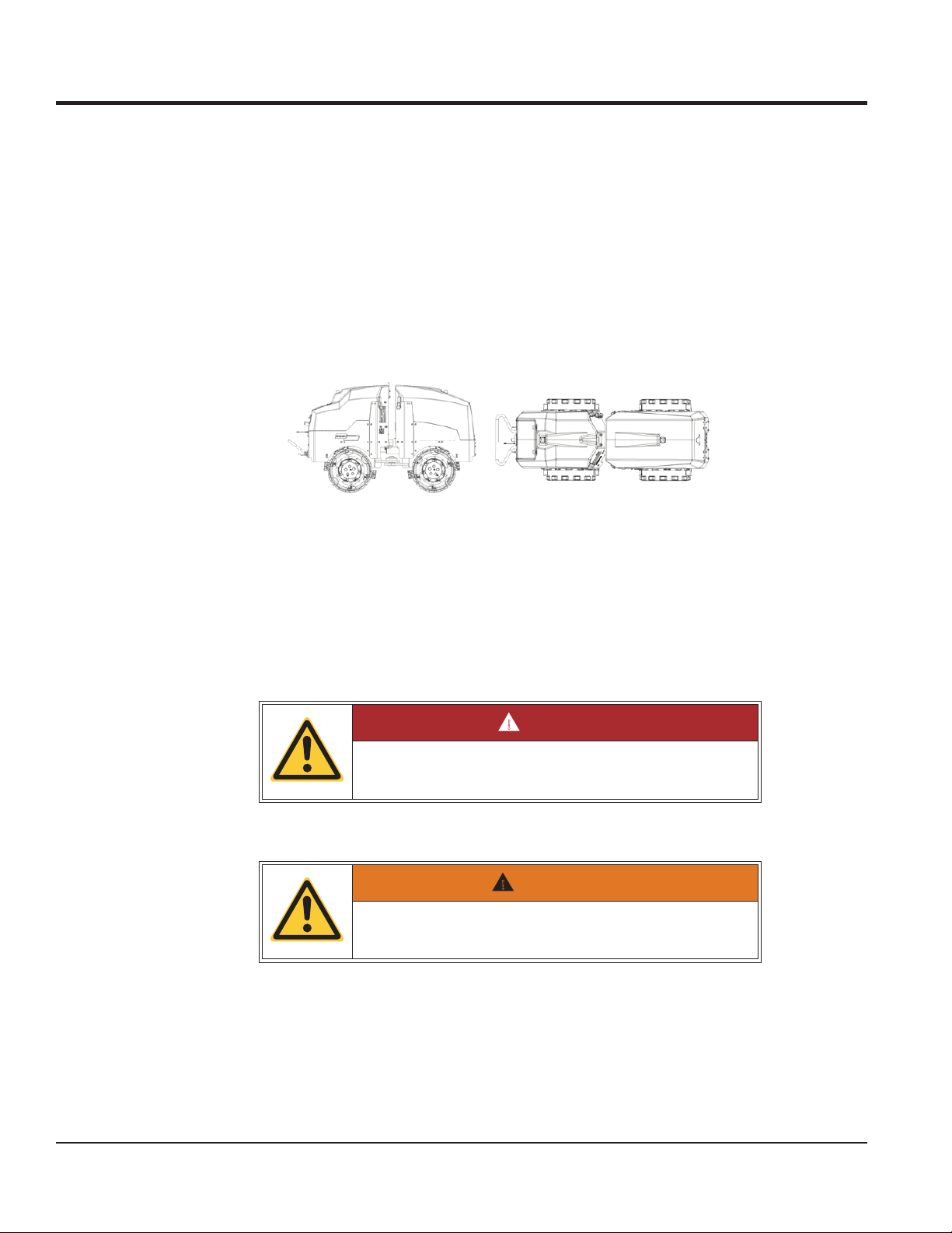
Rear
!
!
commissioning and carrying out maintenance work.
Observing the "safety instructions" in particular increases the reliability of the roller in
operation and its service life. This reduces repair costs and down time.
1.2.1 Orientation on the roller
When describing the components of the roller, we inform you of their position on the
roller. We adhere to the orientation below when doing so.
GENERAL
Fig. 1-1 Rammax 1575 orientation
We view the roller from the position of the driver standing behind the roller looking in
the direction of travel.
1.2.2 Warnings
Please observe the meaning of the following warnings:
Top
Bottom
Left
Front
Right
DANGER
● DANGER represents an immediate hazard leading to severe bodily injury or
death.
WARNING
● WARNING represents a possibly hazardous situation which could lead to se-
vere bodily injury or to death.
PAGE 6 — RX1575 SERIES TRENCH ROLLER • OPERATION MANUAL — REV. #0 (04/28/15)
Page 7

GENERAL
!
CAUTION
● CAUTION represents a possibly hazardous situation which could lead to
slight bodily injury.
● Caution also represents a hazard of environmental pollution causing local or
global environmental damage.
NOTE The battery poles and terminals must be clean. If they are coated with a (whi-
tish or greenish) sulfur crust they must be cleaned.
NOTE Risk of cable fire or short circuit
● NOTE represents first of all: damage which could be caused to the roller or parts
of it.
● NOTE represents secondly: Application tips and other particularly useful informa-
tion.
● NOTE is not a signal word for a hazardous or damaging situation.
RX1575 SERIES TRENCH ROLLER • OPERATION MANUAL — REV. #0 (04/28/15) — PAGE 7
Page 8
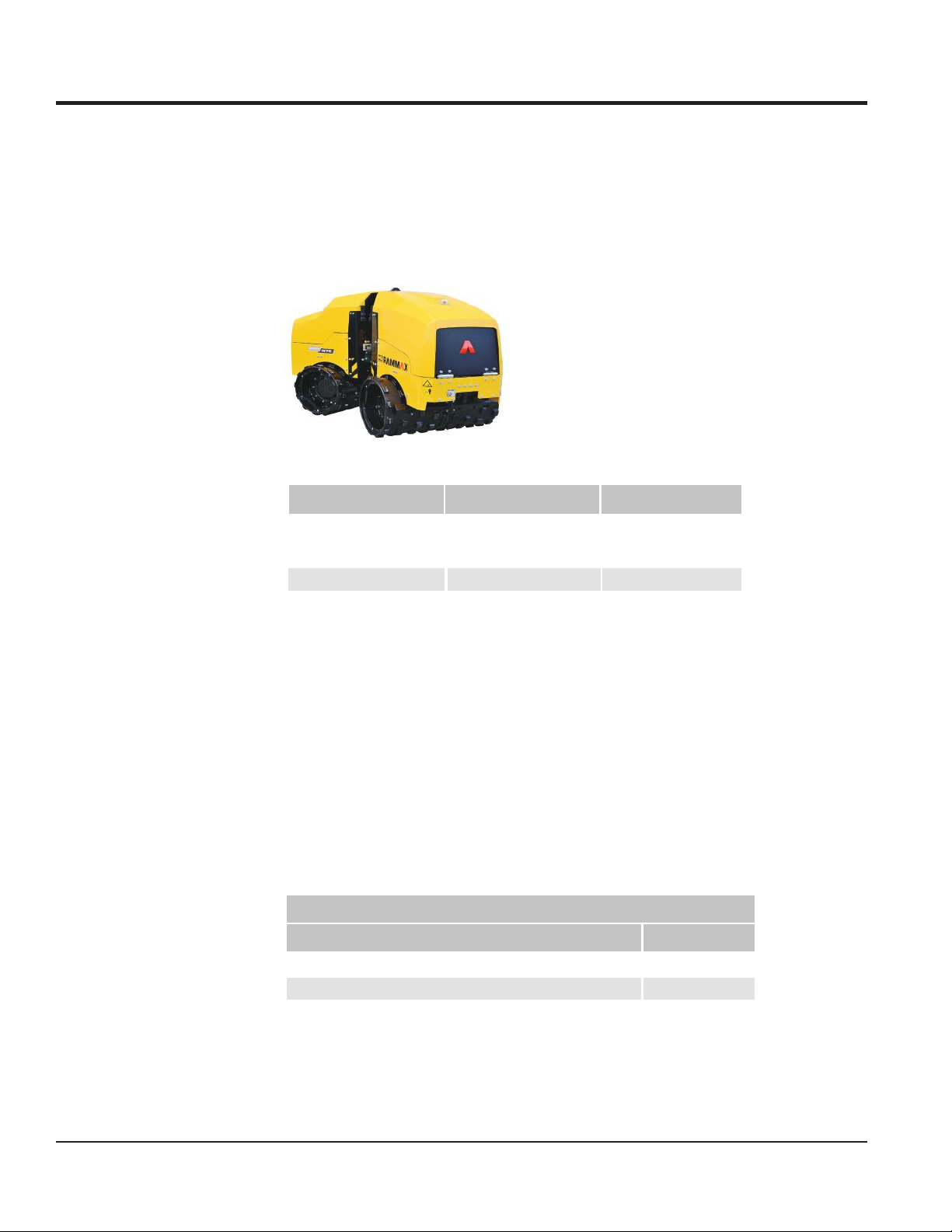
2.1 Identification of the roller
2.1.1 Machine types
The data given below serve to identify the models. The machine models differ only
in terms of weight and the width of the roller drum.
Tab. 2-1 Rammax 1575
Model Roller Drum Width Weight
5751 xammaR
with 24" drums
with drum rings 33 in (850 mm)
Rammax 157533
24 in (640 mm)
33 in (850 mm)
PRODUCT DESCRIPTION
3,087 lbs (1400 kg)
3,197 lbs (1450 kg)
3,197 lbs (1450 kg)
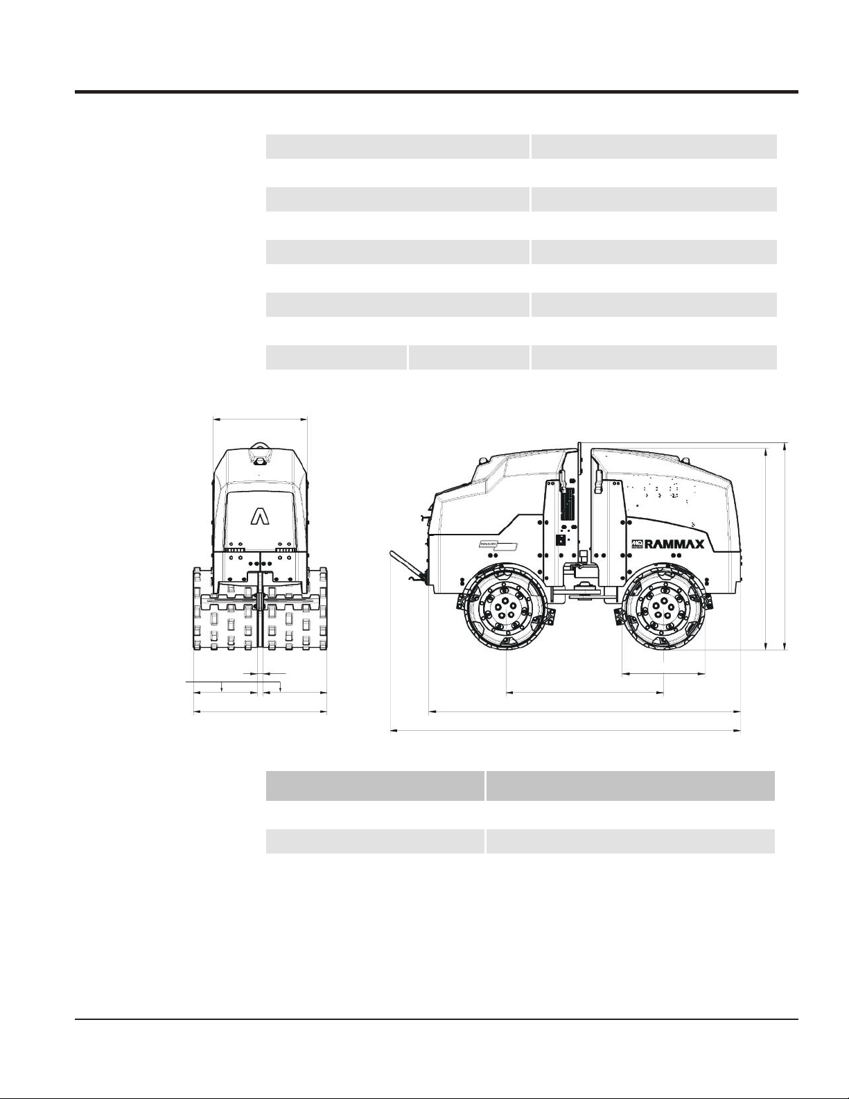
2.2 Product data
2.2.1 Dimensions
Fig. 2-1 1575 dimensions
2.2.2 Specifications
Tab. 2-2 Rammax 1575 performance data
Roller drum width in (mm) 24 (640) 33 (850)
Service weight according to CECE lbs (kg)
Static linear load lbs/in (kg/ cm)
Inside turning radius in (mm) 61 (1541) 57 (1436)
Outside Turning Radius-in (mm) 86.25 (2,191) 90 (2,286)
Rammax 1575
3,087 (1400)
10.1 (11.6) 7.7 (8.9)
3,197 (1450)
PAGE 8 — RX1575 SERIES TRENCH ROLLER • OPERATION MANUAL — REV. #0 (04/28/15)
Page 9
11.89 in (302 mm)/
16.02 in (407 mm)
PRODUCT DESCRIPTION
Low/ High amplitude in (mm) .024 (0.6)/.043 (1.1)
05/04noitarbiv tuohtiw/htiw % ni tneidarG
Drive YANMAR 3TNV76/EPA 4
Wk0.516403 OSI ot gnidrocca ecnamrofreP
/20.4HP
Operating speed 2400 1/min
Low Travel Speed ft/min (m/min)
High Travel Speed ft/min (m/min)
Vibration frequency
23.66 in (601 mm)
1.42 in
(36 mm)
25.20 in (640 mm)/
33.46 in (850 mm)
vpm (Hz)
2,460 (41)
39.37 in (1000 mm)
77.95 in (1980 mm)
87.68 in (2227 mm)
82 (25)
148 (45)
/+/-7°
°03-/+gnitovip/elgna gnireetS
20.67 in
(525 mm)
50.47 in (1282 mm)
51.85 in (1317 mm)
Filling capacities
Tab. 2-3 Rammax 1575 filling capacities
Container Contents
Hydraulic Oil Tank gal (liter)
Diesel Fuel Tank gal (liter)
4.2 (16)
7.4 (28)
RX1575 SERIES TRENCH ROLLER • OPERATION MANUAL — REV. #0 (04/28/15) — PAGE 9
Page 10
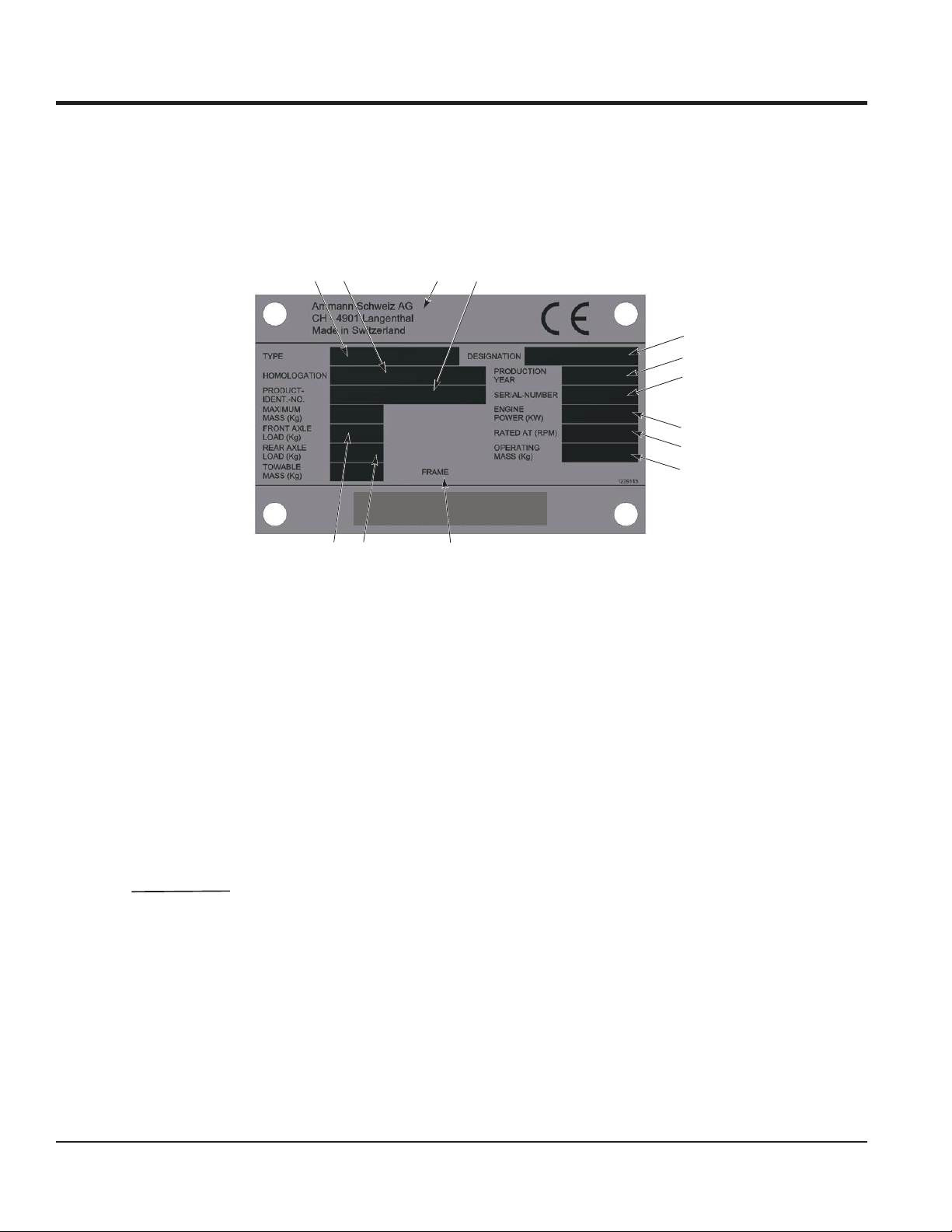
2.3 Roller designation
2.3.1 Identification plate
An identification plate is affixed to the roller for identification. The identification plate
is attached to the rear part of the chassis below the steering column.
Fig. 2-2 Data on the identification plate
NOTE When ordering spare parts you must indicate the serial number (S/N) of the rol-
ler.
1 Roller designation
2 Homologation number
3 Name and address of the manufacturer
4 Vehicle Identification Number (VIN)
5 Roller model
6 Year of manufacture
7 Serial number
8 Fuel engine output at
9 Speed of fuel motor (rpm )
10 CECE total weight
11 Axle load, front
12 Axle load, rear
13 Number stamped in chassis
1
2
5
6
7
8
11
4
9
3
12
10
13
PRODUCT DESCRIPTION
PAGE 10 — RX1575 SERIES TRENCH ROLLER • OPERATION MANUAL — REV. #0 (04/28/15)
Page 11

PRODUCT DESCRIPTION
2.4 Intended use
2.4.1 Intended purpose of the Rammax 1575
The Rammax 1575 trench roller is a roller specially designed for trench compacting.
The unlimited side clearance of the roller drums allows compacting in very narrow,
tight trenches right up to the trench walls. The wet, clayey soils found in sewer construction, pipeline construction, road foundations and construction backfilling, etc., are
the areas of application for this modern trench roller. The infrared remote control also
makes it possible to drive underneath trench shoring in trenches. In hazardous construction site applications, it is possible for the operator to control the machine from a
safe distance with no personal risk.
Normal modes of
operation
Special operating
modes
Use the Rammax 1575 roller exclusively for driving on and compacting:
● Unbonded layers (earth, gravel, crushed stone).
● Transport of the roller from A to B (crane and low loader).
● Cleaning the roller.
● Maintenance of roller according to maintenance plan or in the event of defects.
● Rectification of machine faults by trained personnel based on error messages.
● Towing the roller.
● Proper disposal by the operator in accordance with national regulations.
2.4.2 Requirements for the roller driver
Only trained, suitable and reliable specialists may operate the rollers.
2.4.3 Application limits
Tab. 2-4 Limits for application in consideration of environmental conditions
Operation Storage
Temperature limit -10°C to +48°C -25°C to +48°C
Humidity All-year operation/outdoor storage
Terrain Graded Graded
Upslope 40% with -/50% without vibration max. 15%
Downslope 40 % with -
/50% without vibration max. 15%
RX1575 SERIES TRENCH ROLLER • OPERATION MANUAL — REV. #0 (04/28/15) — PAGE 11
Page 12

1230047 | 21.06.2013
2.5 Inappropriate use
Inappropriate use includes any use not listed under intended use. Note the following
in particular:
● The roller is not a playground.
● The roller must not be used as a traction vehicle.
● The roller is not a passenger transporter.
● In the case of movements greater than 3km, the roller must be loaded on a trans-
porter.
● The roller is not a rock crusher, breaking chisel or similar.
2.5.1 Disclaimer
Ammann Schweiz AG accepts no liability for the continued reliable functioning of the
roller if it is not used appropriately.
Unauthorized conversions and changes to the roller are prohibited for safety reasons
and void any and every Ammann guarantee as well as, possibly, the CE directive.
Replaced spare or wear parts must meet the technical requirements specified by
Ammann. These requirements are fulfilled if only original Ammann spare parts are
used.
PRODUCT DESCRIPTION
The instructions given in the various sections must be adhered to. The safety instructions must be observed at all times. Failure to adhere to working instructions, their
correct order, safety instructions or safety labeling requirements causes liability
claims to become void.
PAGE 12 — RX1575 SERIES TRENCH ROLLER • OPERATION MANUAL — REV. #0 (04/28/15)
Page 13

1230047 | 21.06.2013
3.1 General working safety
!
● The roller may only be used for driving on and compacting loose top layers (gra-
vel, earth). Other uses are prohibited.
● Rollers may only be operated with all safety devices operating. Manipulation or
disregard of safety devices and regulations invalidates the CE conformity.
● Before starting every shift, check the effectiveness of the operation and safety de-
vices and that the protection devices are in place.
● Check the steering and brakes when you start work. If defects are apparent, roller
operation is not permitted.
● If you identify any defects on the safety system or defects that impair safe opera-
tion of the equipment, inform your supervisor immediately. The roller may no longer be operated.
● If you identify any defects which endanger safe operation, cease operation imme-
diately.
● Only perform work on and clean the roller if it is stationary and secured from
rolling away.
● Switch off the engine when filling the fuel tank. Do not fill up fuel in enclosed spa-
ces. No open flames.
● Do not vibrate on slopes or inclines where there is a hazard of slipping or overtur-
ning.
● Do not drive on slopes that are steeper than the maximum climbing capacity of
the equipment. Always drive the roller carefully perpendicular to the slope dip.
● Do not vibrate inside buildings and on unstable ground.
● The driving and working field of view must not be obstructed in any way.
● Switch off the engine before leaving the roller. Secure the roller against unautho-
rized start-up and rolling away.
● Take suitable visible measures to secure parked rollers that pose an obstruction.
● Never work under the influence of drugs, alcohol or medicines that impair consci-
ousness.
● Only operate the roller in good general light conditions and good workspace illu-
mination.
● The workplace of the operator is located at a safe distance of at least 2m.
SAFETY INFORMATION
3.2 Roller operation
DANGER
Rollover hazard when driving the roller!
• Only start the roller using the handheld transmitter.
• Personnel may not stand in front of or behind the roller while it
is in operation.
• Persons necessary for operations at the sides of the equipment
must remain at a safe distance of at least 2 m.
RX1575 SERIES TRENCH ROLLER • OPERATION MANUAL — REV. #0 (04/28/15) — PAGE 13
Page 14
3.2.1 Shear points
A
● When closing the hood ensure that no objects are situated between the hood and
the chassis.
● Take care that nothing is jammed in the joint plates when rotating the roller drums.
● Do not put hands between the roller drum and support during operation.
SAFETY INFORMATION
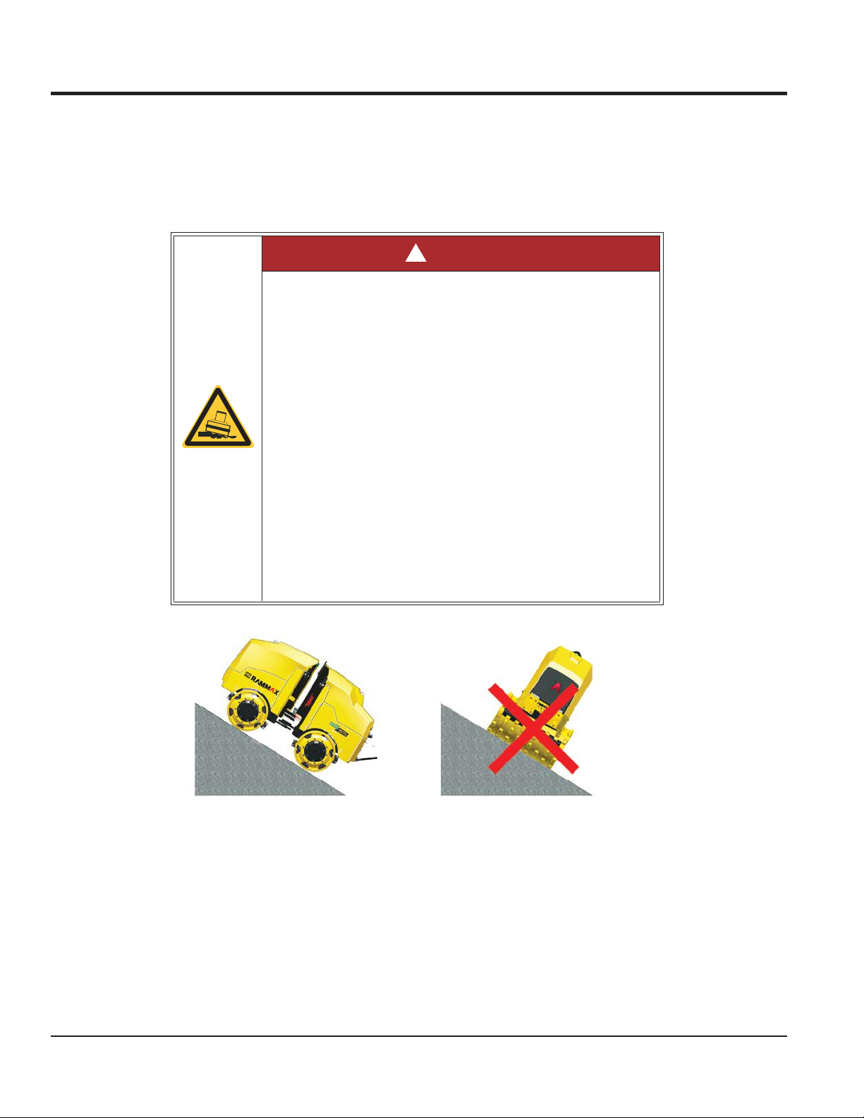
DANGER
Danger to life through tipping or slipping of the roller! The edges of filled areas may give way!
• Only travel directly up or down slopes.
• Do not drive across slopes.
• Keep your distance to embankments and edges!
• Do not drive at an angle into or out of the trench.
• Park the roller on slopes only in such a way that it cannot overturn.
• Use the roller on slopes only in such a way that it cannot overturn.
• The roller drums have very poor adhesion on snow and ice. Driving or working on a slope in snow or ice is prohibited.
• Damp a
upward and downward grades considerably. Adapt the speed
of the machine to the terrain when driving on grades.
• The nature of the ground and weather conditions can negatively affect the climbing ability of the machine.
Never drive on slopes that are steeper than the maximum climbing ability of the machine.
nd loose surfaces reduce the traction of the machine on
Fig. 3-1 Tipping hazard
Construction site conditions can have a negative effect on stability and the tipping
angle.
PAGE 14 — RX1575 SERIES TRENCH ROLLER • OPERATION MANUAL — REV. #0 (04/28/15)
Page 15

1230047 | 21.06.2013
!
!
!
!
SAFETY INFORMATION
DANGER
Crushing hazard in the area of the articulated joint
• During operation, there is always a crushing hazard in the area
of the articulated joint. Therefore, it is not permitted for persons
to be in this area during operation. In general, a safety distance
of at least 2 meters to the machine must be maintained during
operation.
DANGER
Crushing of toes through careless handling of the roller!
• Wear safety shoes when working with the roller in order to help
avoid crushed toes.
DANGER
3.3 Noise levels
The following noise level measurements were carried out by an accredited testing
and monitoring body in accordance with machine directive 2000/14/EEC of the
European parliament and council.
Danger of accident through improper operation of the roller!
• Read the operating instructions before operating the roller.
• Adhere to the safety regulations at all costs.
• In case of lack of clarity, contact your authorized dealer.
WARNING
Hearing damage due to continuous noise level!
Depending on the use of equipment it is possible that the allowed noise level of 85dB (A) will be exceeded.
• Wear ear protectors in accordance with national accident prevention regulations when working at higher noise levels.
Inspecting and monitoring organization: TÜV Österreich (Austrian technical inspectorate) Testing body no. 0408
RX1575 SERIES TRENCH ROLLER • OPERATION MANUAL — REV. #0 (04/28/15) — PAGE 15
Page 16

SAFETY INFORMATION
Tab. 3-1 Sound power level
Model Value
Measured sound power level 100dB (A)
NOTE The obligation to wear ear protection is standardized nationally. In Switzerland
and Germany, this is as of a measured level of 85dB (A) (sound pressure).
3.4 Safety markings on the machine
● Observe and adhere to the rules.
● Keep the safety stickers and signs complete and legible.
● Replace any damaged or illegible stickers and signs immediately.
● You can order new stickers from Ammann Schweiz AG.
From the moment the signs are no longer recognizable and understandable at first
glance, the machine must be shut down until new signs are installed.
3.4.1 Warning stickers
Tab. 3-2 Warning stickers on board
Warning stickers Meaning
Location on roller:
Air intake opening
Danger:
Damage to electrical controls!
Explanation:
Never spray a water jet into electrical or electronic components.
Never spray into the engine combustion air intake.
Location on roller: Outer cowling cover.
Danger: Danger of injury due to incompetent operation:
Explanation: Read the operating instructions before ope-
rating the roller. Adhere to the safety regulations at all
costs. Contact your authorized dealer if anything is unclear.
/Inside of cowling
PAGE 16 — RX1575 SERIES TRENCH ROLLER • OPERATION MANUAL — REV. #0 (04/28/15)
Page 17

1230047 | 21.06.2013
Warning stickers Meaning
Location on roller: Between the front and rear parts of
the roller.
Danger: Crushing hazard!
Explanation: Only stand in this area when necessary and
only with extreme caution!
Location on roller: In the middle of the front and back.
Danger:Rollover hazard
Explanation: Only stand in this area when necessary and
only with extreme caution!
SAFETY INFORMATION
Location on roller: Radiator, both sides.
Danger: Warnings for cooling water radiator
Explanation: Do not put hands in the radiator fan when
the machine is running.
RX1575 SERIES TRENCH ROLLER • OPERATION MANUAL — REV. #0 (04/28/15) — PAGE 17
Page 18

SAFETY INFORMATION
Warning stickers Meaning
Location on roller: Inner cowling cover.
Designation: If the roller has overturned, do not start the machine.
Explanation: Avoid oil shock.
Location on roller: Outer cowling cover.
Requirement: Wear ear protectors!
Explanation: Wear ear protectors in accordance with nati-
onal accident prevention regulations when working at higher noise levels.
3.4.2 Notice stickers
Tab. 3-3 Notice stickers on board
Notice stickers Meaning
Location on roller: Chassis rear
Designation: Guaranteed sound power level.
Explanation: Indicates the overall noise level produced by
the roller.
Location on roller: On the hydraulic oil tank
Designation: Hydraulic oil
Explanation: Please only use hydraulic oil indicated
PAGE 18 — RX1575 SERIES TRENCH ROLLER • OPERATION MANUAL — REV. #0 (04/28/15)
Page 19

1230047 | 21.06.2013
Notice stickers Meaning
Location on roller: Chassis rear.
Designation: Hydraulic oil drain.
Explanation: Drain hole for the hydraulic oil
Location on roller: Chassis, front right.
Designation: Motor oil drain.
Explanation: Drain hole for the motor oil
Location on roller: Chassis rear.
Designation: Fuel.
Explanation: Filler neck for diesel fuel.
Location on roller: On the middle of the front and rear
chassis.
Designation: Tie-down point.
Explanation: Points on the roller at which lashing means
for securing the roller on the transport vehicle can be attached.
SAFETY INFORMATION
Location on roller: Roll bar, rear.
Designation: Suspension hooks.
Explanation: Points on the roller at which hoisting tackle
for lifting the roller can be attached.
Location on roller: Rear chassis, front upper left.
Designation: Lifting and tie-down points.
Explanation: Illustrates how the machine is to be loaded
and transported.
RX1575 SERIES TRENCH ROLLER • OPERATION MANUAL — REV. #0 (04/28/15) — PAGE 19
Page 20

Notice stickers Meaning
Location on roller: Rear chassis, front upper left.
Designation: Spare parts information
Explanation: Information about the filters of the machine.
Location on roller: Inner cowling cover.
Designation: Close the cover.
Explanation: Attention: When driving using remote cont-
rol and when parking the machine, the cover must be closed.
Location on roller: Inner cowling cover.
Designation: Ignition
Explanation: Attention: Current is present when the igni-
tion is on.
SAFETY INFORMATION
3.5 Radiation compliance
This machine complies with the emission requirements for radio interference due to
radiation, European Norm EN 13309, for construction machinery.
PAGE 20 — RX1575 SERIES TRENCH ROLLER • OPERATION MANUAL — REV. #0 (04/28/15)
Page 21

4.1 Component overview
Fig. 4-1 View from the right
1 1-point lifting eye
2 Identification plate
3 Roller drum scraper
4 Rear hood latch (cowling)
5 Front hood latch (engine hood)
6 Front infrared sensor
STRUCTURE AND FUNCTION
Fig. 4-2 View from left
1 Articulated joint protection
2 Shutdown bar (optional)
3 Cockpit cover
4 Rear infrared sensor
RX1575 SERIES TRENCH ROLLER • OPERATION MANUAL — REV. #0 (04/28/15) — PAGE 21
Page 22

STRUCTURE AND FUNCTION
Fig. 4-3 Cockpit overview
1 Infrared transmitter
2 Storage area for spiral cable
3 Display unit
4 Ignition switch
5 Fuses
6 Connector for spiral cable to infrared sensor (back area)
2
Fig. 4-4 Overview of interior of rear chassis
1 Oil cooler
2 Fuel tank
3 Hydraulic tank
4 Battery
5 Controller (machine controller)
1
3
4
5
PAGE 22 — RX1575 SERIES TRENCH ROLLER • OPERATION MANUAL — REV. #0 (04/28/15)
Page 23

1230047 | 21.06.2013
Fig. 4-5 Front bottom view
1 Engine oil drain plug
STRUCTURE AND FUNCTION
RX1575 SERIES TRENCH ROLLER • OPERATION MANUAL — REV. #0 (04/28/15) — PAGE 23
Page 24

1230047 | 21.06.2013
5.1 Display unit
5.1.1 Control lamps
OPERATING AND DISPLAY ELEMENTS
1 Display/operating hours counter
2 Control lamp f
3 Error control lamp
4 Control lamp for engine oil pressure
5 Control lamp for cooling water temperature
6 Control lamp for shutdown bar
7 Control lamp for pre-heating
The control lamps for engine oil pressure and charging light up when the ignition is
switched on. They extinguish once the engine is running.
or battery charge level (charge control)
5.1.2 Control lamp functions
Error The Error control lamp lights as soon as the controller recognizes an error. Error
codes are shown on the LED display.
1 Check whether the desired function is working. (This also applies when the tilt
sensor is triggered.)
If the battery charging lamp is still lit after carryin
g out these checks, call a specialist.
PAGE 24 — RX1575 SERIES TRENCH ROLLER • OPERATION MANUAL — REV. #0 (04/28/15)
Page 25

!
OPERATING AND DISPLAY ELEMENTS
Battery If the battery charge level control lamp lights up during operation or does not go
off after starting, carry out the following check immediately.
1 Stop the engine.
2 Check the engine for defective or loose V-belt.
If the battery charging lamp is still lit after carrying out these checks, call a specialist.
Engine oil pressu-reIf the engine oil pressure control lamp lights up during operation or does not go off
after starting, stop the roller and turn off the engine immediately!
1 Check the engine for oil loss and correct oil level.
1.1 The oil level in the engine is correct: Call a specialist to remedy the pro-
blem.
NOTE The machine is equipped with an automatic shutdown system. If the oil pres-
sure falls below the limit value, the oil pressure warning lamp lights up. After
the warning lamp has been lit for 4 seconds, the machine is shut down.
Coolant temperature
WARNING
Danger of scalding! The cooling circuit is pressurized.
NOTE Danger of engine overheating. Stop immediately!
If the coolant temperature control lamp lights up during operation of the machine,
switch off the engine immediately and top up coolant!
1 Allow the engine to cool down.
2 Remove the radiator cap.
3 In order to avoid scalding, first unscrew the radiator cap one turn and allow the
pressure to drop.
4 As soon as the pressure has dropped, remove the cap and top up the liquid.
5 Check the cooling system for leaks and the radiator/expansion vessel for cor-
rect coolant level.
5.1 You are unable to find an error: Call a specialist to remedy the problem.
NOTE The machine is equipped with an automatic shutdown system. If the cooling
water temperature exceeds the limit value, the temperature warning lamp
lights up. After the warning lamp has been lit for 4 seconds, the machine is
shut down.
RX1575 SERIES TRENCH ROLLER • OPERATION MANUAL — REV. #0 (04/28/15) — PAGE 25
Page 26

1230047 | 21.06.2013
Pre-heating The pre-heating time lasts about 6 s. The pre-heating indicator lamp extinguishes
when the engine is started.
Shutdown bar
The shutdown bar indicator lamp remains lit as long as the shutdown bar is actuated.
1 Check whether the shutdown bar has been released.
2 Release the shutdown bar.
5.1.3 LED error display on the display unit
Error display
Tab. 5-1 Error display (tilt switch)
NOTE For safety reasons, as soon as the roller tips over, the ignition is also shut off.
The machine controller is equipped with an inclination sensor. It triggers as of
an angle of 45°. In this case, the engine shuts itself off automatically. The machine cannot be started as long as the inclination sensor remains triggered.
If the machine has tipped over, it is possible for engine oil to enter the combustion area. If the machine is started after it has been righted, engine damage is
possible.
• Set the machine upright. Do not start the engine un
der any circumstances.
• Inform the service workshop.
Tab. 5-2 Error and shutdown bar display
NOTE Bear in mind the priority of the displays: First is the tilt switch, then “Wait” and
last, the status error transistor.
Display Cause Remedy
Error lights up The tilt switch has been triggered.
The roller is at an angle of more
than about 45° or has tipped over.
Set the machine upright.
Display Cause Remedy
Error lights up A switching transistor signals
a status error. This means
that, for example, a short circuit or a cable break has
been detected.
Check the cable for a short circuit or cable break.
Error and shutdown
bar light up in unison
The machine controller is
waiting for both the inputs “Oil
pressure” and “Lima” to be at
the rest position.
Check the oil pressure and lima
outputs.
(OPTIONAL)
OPERATING AND DISPLAY ELEMENTS
PAGE 26 — RX1575 SERIES TRENCH ROLLER • OPERATION MANUAL — REV. #0 (04/28/15)
Page 27

OPERATING AND DISPLAY ELEMENTS
Display
Tab. 5-3 Shutdown bar display
Shutdown bar
Display Cause Remedy
Shutdown bar lights up Switch on shutdown bar has
Shutdown bar is blinking
Shutdown bar is flashing
triggered.
Close proximity shutdown
has been detected.
Close proximity has been
detected.
Move the shutdown bar to its original position.
Move more than 2m away from
the roller.
If the roller is controlled by
means of the cable, the user
must be present in the close
proximity area (between 2 and
4m)
NOTE Bear in mind the priority of the displays: First the bar switch, then the close
proximity shutdown and last, the close proximity area.
5.2 Infrared transmitter
5.2.1 Design
Fig. 5-1 Infrared transmitter
1 Work gear/transport gear
2 Forward travel/backward travel
3 Large/small amplitude vibration
4 Steering angle left/ right
RX1575 SERIES TRENCH ROLLER • OPERATION MANUAL — REV. #0 (04/28/15) — PAGE 27
Page 28

1230047 | 21.06.2013
OPERATING AND DISPLAY ELEMENTS
5 Start/ Stop
6 LED (error and charging display from IR transmitter)
7 Cable
5.2.2 LED error display on the IR transmitter
There are two LEDs on the cover: a green one and a red one.
Fig. 5-2 LED error display, green/red
Standard
Battery charge
monitoring
Tab. 5-4 Standard display
Display Cause
The green LED is blinking slowly. The roller is being controlled via the cable.
The green LED is flashing. The roller is being controlled via infrared.
The red LED blinks either faster or slower depending on the battery charge level. The lower
the charge state, the longer the on-phase of the LED.
Tab. 5-5 Battery charge monitoring display while performing a function
Display Cause Remedy
The red LED flashes briefly The battery is slowly
The red LED always lights when a
control is operated.
The red LED flashes. The battery is being
The red LED is lit. The battery is fully
becoming drained
When the battery is
drained, it is no longer
sent.
charged.
charged.
Connect the charging
cable for at least 1h.
Connect the charging
cable for at least 1h.
NOTE It is still possible to control via the cable once the battery is empty.
Battery warnings and errors are only displayed during active control (i.e., when
a control element is actuated).
As soon as and as long as the infrared transmitter is attached to the machine
controller via the cable and the ignition is turned to I, the red LED must flash
or be lighted.
PAGE 28 — RX1575 SERIES TRENCH ROLLER • OPERATION MANUAL — REV. #0 (04/28/15)
Page 29

OPERATING AND DISPLAY ELEMENTS
Automatic pairing
NOTE This procedure normally only takes a maximum of about 3seconds. If this blin-
Special cases
Tab. 5-6 Automatic pairing display
Display Cause
The green and red LEDs are blinking in unison quickly.
king lasts longer or should even become permanent, there is a problem with
pairing:
• A cable break in one of the signal lines
• A short circuit in one of the signal lines
As long as this blinking pattern remains, no control signals will be sent to the
machine controller.
Automatic pairing occurs at the moment the cable is unplugged, or, if the cable
is plugged in, when the infrared transmitter is switched on.
● When the infrared transmitter is switched on, both LEDs are switched on briefly.
This feature helps to determine that the LEDs are still functioning.
● As soon as the cable is unplugged from the handheld transmitter or from the rol-
ler, the red LED lights up for about 1 second.
The infrared transmitter is coupled with the
machine controller.
5.2.3 Cable connection
Fig. 5-3 Spiral cable connector
1 Spiral cable connector/protective cover fastener
2 Solar cells/Transmission elements
RX1575 SERIES TRENCH ROLLER • OPERATION MANUAL — REV. #0 (04/28/15) — PAGE 29
Page 30

1230047 | 21.06.2013
5.2.4 Handling
!
Sticker
The infrared transmitter is located in the black lower part of the housing. It contains
the following transmission elements:
● The solar cells
● The infrared diodes for data transmission and measuring the safety distance.
● Before startup, clean the transmission elements.
● Before startup, be sure that the solar cells in the lower part of the housing are not
covered over.
● Keep the solar cells clean during operation.
OPERATING AND DISPLAY ELEMENTS
CAUTION
Accident hazard due to covered over lower part of the
housing!
• Before and during operation with the infrared transmitter, make
sure that the entire lower part of the housing remains completely uncovered for the entire time of operation.
• In particular, the operator’s hand must not cover the lower part
of the housing even partially.
Wear the infrared transmitter correctly
1 Pay attention to correct positioning.
1.1 The cable connector must face forwards or be oriented according to the
sticker on the transmitter. The infrared transmitter may rest on the stomach of the operator.
1.2 Adjust the strap for the correct length to ensure optimal wearing comfort.
2 Pay attention to correct operation.
2.1 Only hold the housing by the upper part; see the warning information.
PAGE 30 — RX1575 SERIES TRENCH ROLLER • OPERATION MANUAL — REV. #0 (04/28/15)
Page 31

OPERATING AND DISPLAY ELEMENTS
RX1575 SERIES TRENCH ROLLER • OPERATION MANUAL — REV. #0 (04/28/15) — PAGE 31
Page 32

1230047 | 21.06.2013
6.1 Commissioning
NOTE Familiarize yourself with the manual before commissioning.
6.1.1 Inspection before commissioning
In order to begin operating the roller (driving), the following conditions must be fulfilled:
The following must be checked:
● The function of all safety devices
● Whether the transport restraint has been removed
● Whether the shutdown bar has been released
● All screw connections for tightness
● Fuel tank and pipes for leaks
● Machine and engine for damage
● Function of the controls
● Function of the steering
● Hydraulic system for leaks
● IR transmitter battery status (LED must be lit).
● Pair infrared transmitter with the machine controller (see below).
● Electronic ballast interference (an external influence from fluorescent tubes)
COMMISSIONING
NOTE The infrared transmitter does not work and no LEDs are lit.
• Connect the transmitter to the machine via the spiral cable. The battery will
be charged!
6.1.2 Automatic pairing of infrared transmitter and machine controller
In order to operate the machine using the infrared transmitter, they must first perform
a mutual address assignment. This is only necessary if a new infrared transmitter
must be registered on the machine.
1 Connect the cable to the transmitter.
2 Turn the ignition key to position I.
3 After approx. 3 seconds, the cable can be removed.
The cable is not required for infrared operation.
NOTE Pairing is required in order to operate the machine with a new infrared trans-
mitter. Pairing ensures that only one machine can be operated with one transmitter.
The green LED and the red LED blink during pairing
PAGE 32 — RX1575 SERIES TRENCH ROLLER • OPERATION MANUAL — REV. #0 (04/28/15)
Page 33

1230047 | 21.06.2013
7.1 Protection against vandalism
Always fold the vandalism protection cover upward before start-up of the roller.
The vandalism protection cover protects the display unit and the infrared sensor
from:
● the effects of weathering
● vandalism
● alterations by third parties
If you wish to secure the display unit and the infrared sensor from unauthorized
access by third parties, you can install a padlock on the loop provided for this purpose.
Commercially available padlocks can be obtained in any building supplies store.
OPERATION
Fig. 7-1 Vandalism protection cover opened/closed
7.2 Start the engine
7.2.1 Starting the engine using the ignition switch
0 Off
All electrical loads are off.
I Ignition on
All electrical consumers can be switched on.
II Pre-heating
III Start
7.2.2 Starting the engine using the infrared transmitter
1 Turn the ignition key clockwise to position I.
2 Hold the switch on the infrared sensor in the start position.
2.1 Preglow for a max. of 6sec.
3 Release the switch.
RX1575 SERIES TRENCH ROLLER • OPERATION MANUAL — REV. #0 (04/28/15) — PAGE 33
Page 34

OPERATION
Fig. 7-2 Start the engine/Infrared sensor
NOTE The control lamps for engine oil pressure and charging light up when the igni-
tion is switched on. They extinguish once the engine is running.
Pre-heating If the outside temperature is below 0°C:
1 Turn the ignition key to position II.
1.1 Hold it in this position for max. 6 sec.
2 Turn the ignition key further to position III.
NOTE The engine is always to be started at idling speed.
NOTE If the ignition key remains at position I and the machine has not yet been star-
ted or has just been shut off, then:
• The machine goes into standby mode automatically after 10minutes.
Standby
NOTE If the ignition key remains at position I and the machine has not yet been star-
OFF
It is possible at any time to start the machine via the transmitter, using the cable operation mode or via the ignition switch.
ted or has just been shut off, and no function is activated within 4hours, then:
• The machine controller shuts itself off completely.
To be able to start the machine, the ignition key must first be moved to position 0 briefly.
PAGE 34 — RX1575 SERIES TRENCH ROLLER • OPERATION MANUAL — REV. #0 (04/28/15)
Page 35

1230047 | 21.06.2013
7.3 Driving and braking
7.3.1 Position of the operator
Distance to roller:
< 6.5 ft (2m) Operation is not possible.
> 13 ft (4m) Cable is too short, operation is not possible (do not overstretch the cable).
OPERATION
156 in
Fig. 7-3 Position of the operator/Distance to roller
Overview of functions
Operation with the cable Operation with the infrared sensor
Automatic pairing
Steering functions
Vibration functions
max. range = 13 ft (4 m) max. range = 65 ft (20 m)
Close proximity shutdown, 6.5 ft (2 m)
RX1575 SERIES TRENCH ROLLER • OPERATION MANUAL — REV. #0 (04/28/15) — PAGE 35
Page 36

OPERATION
Controller
opening angle
0°
10°
20°
30°
40°
50°
60°
70°
2 4 6 8 10 12 14 16 18 20 m
Fig. 7-4 Controller opening angle
NOTE After a function has been executed, the engine speed is automatically increa-
sed to the working speed. If no function is executed for 15 seconds, the engine
speed is automatically reduced to idling speed.
7.3.2 Driving forwards/backwards
1 Move the switch:
2a Toward the front: The roller moves forward.
2b Toward the rear: The roller moves backward.
7.3.3 Steering left/right
1 Move the switch:
2a Toward the left: The roller moves left.
2b Toward the right: The roller moves right.
7.3.4 Work gear /Transport gear
The roller is equipped with two gears.
1 Move the switch:
2a Toward the top (rabbit): the hydraulic system switches to the "transport gear"
drive level.
The roller drives at a high speed.
2b Toward the bottom (0): the hydraulic system switches to the “working gear"
drive level. The roller drives at a low speed.
PAGE 36 — RX1575 SERIES TRENCH ROLLER • OPERATION MANUAL — REV. #0 (04/28/15)
Page 37

1230047 | 21.06.2013
NOTE Please also bear the following in mind:
!
• When large/small vibration is switched on, it is only possible to drive in the
working gear.
• When the machine is cold, the difference between high speed and low
speed is minimal.
7.3.5 Large/small amplitude vibration
1 Move the switch:
2a Toward the top: The roller vibrates with a large amplitude.
2b To the center: The roller does not vibrate.
2c Toward the bottom: The roller vibrates with a small amplitude.
Danger to life through slipping or caving in of the roller!
• Do not use vibration on steep embankments or at steep angles!
• Do not vibrate inside buildings and on unstable ground!
OPERATION
WARNING
NOTE Damage to material due to harsh vibration movement.
• Never use vibration while at a standstill! If the large/ small vibration function
is activated for more than 15seconds while at a standstill, the machine controller shuts it off automatically.
• When first started, it is only possible to use the small amplitude vibration
function for the first 2minutes.
7.4 Safety and monitoring equipment
7.4.1 Brake
The machine is equipped with an hydraulic service brake. It is switched on automatically when no function is being executed.
NOTE When a function is once again performed, there may be a jerking movement.
This has no effect on the stability of the machine.
7.4.2 Close proximity and distant shutdown
The close proximity and distant shutdown function is an electronic safety feature
designed to prevent the operator from loosing visual contact with the machine and to
keep it from coming to close.
RX1575 SERIES TRENCH ROLLER • OPERATION MANUAL — REV. #0 (04/28/15) — PAGE 37
Page 38

!
OPERATION
All of the distance values indicated are measured between the front or back infrared
sensor and the infrared transmitter.
The table below shows the approximate distance values for this feature.
Tab. 7-1 Distance values for close proximity and distant shutdown
Cable operation IR operation
Close proximity shutdown approx. 6.5 ft (2 m) approx. 6.5 ft (2 m)
Distant shutdown approx. 13 ft (4 m) approx. 65 ft (20 m)
NOTE The distance values can vary in dependence on weather conditions. If the ma-
ximum range is exceeded in infrared operation/cable operation, the diesel engine continues to idle, but the functions are interrupted. Reduce the distance
to the machine in order to resume control of it.
7.5 Turning off the engine
1 Move the switch on the infrared transmitter to “STOP”.
2 Turn the ignition key to the “0” position.
CAUTION
As long as the “Start-Stop” rocker switch is placed in the
“neutral” position, the transmitter remains operational.
• Always switch off the transmitter during work breaks and after
completing work by moving the rocker switch to the “Stop” position.
PAGE 38 — RX1575 SERIES TRENCH ROLLER • OPERATION MANUAL — REV. #0 (04/28/15)
Page 39

1230047 | 21.06.2013
8.1 Shutdown bar (OPTIONAL)
The shutdown bar is located on the rear of the machine under the operating unit. A
proximity switch is located on the rear section of the machine above the attachment
point of the shutdown bar. If the machine moves against an obstacle with the shutdown bar, the shutdown bar is actuated and triggers the proximity switch. This sends
a signal to the machine controller and the machine can now only be moved forward
away from the obstacle. If the vibration function is
vibration function must be restarted manually after the
tivated. The shutdown bar must be secured with the transport strap for transportation
(transport position).
OPTIONS
running, it will be shut down. The
shutdown bar has been deac-
Fig. 8-1 Shutdown bar
1 Shutdown bar
2 Securing point for strapping down the shutdown bar
3 Proximity switch
RX1575 SERIES TRENCH ROLLER • OPERATION MANUAL — REV. #0 (04/28/15) — PAGE 39
Page 40

1230047 | 21.06.2013
9.1 General safety information
!!!
Maintenance may only be carried out by trained personnel!
● Only perform maintenance and repair work on the roller if it is static and secured
from rolling away.
● Secure the roller with the joint protection.
● Relieve pressure before working on the hydraulic pipes.
● Disconnect the battery before commencing work on the roller's electrical systems.
○ Cover the battery with isolating material or remove it completely. This does not
apply to work requiring an electric current.
○ In the event of injuries caused by acid, rinse immediately with clean water and
consult a doctor.
● Replace all protection devices properly after performing maintenance and repair
work.
Danger to life through an unsafe work area!
• Always use an accident-proof support when working on a raised roller.
• Never work below a roller which is only supported by a crane or
other electrical/hydraulic lifting device.
• Only stand under a raised roller if it has been mechanically secured.
• Only use stable loading ramps suitable for the weight of the roller for loading.
• On transport vehicles, correctly secure the roller against rolling,
slipping and overturning.
MAINTENANCE
DANGER
DANGER
Gas poisoning through letting engine run in enclosed spaces!
• Do not leave the engine running in closed areas.
• If use of the roller in a confined space cannot be avoided, the
exhaust fumes must be extracted directly from the exhaust pipe.
DANGER
Danger of scalding from hot water / steam!
• Never remove the expansion cap or radiator cap while the engine is running or hot!
• First loosen the cap to the first stop to release the pressure.
Only then remove the cap.
PAGE 40 — RX1575 SERIES TRENCH ROLLER • OPERATION MANUAL — REV. #0 (04/28/15)
Page 41

!
!
!
MAINTENANCE
DANGER
Danger of severe injury through loose clothing being caught
and drawn in!
• Only open the engine hood when the engine is switched off.
• If trouble shooting makes working on moving parts (engine or
roller) unavoidable, never wear: necklaces, bracelets, rings,
scarves, ties or other loose items of clothing.
If any of these get caught in moving parts there is a danger of
serious injury!
WARNING
Danger of scalding from hot water / steam!
• Only work on a cool engine.
• Keep enough distance to the exhaust.
CAUTION
Environmental hazard through operating materials!
• Do not allow any liquids to enter drains, the soil or the environment.
NOTE Damage to electrical controls through contact with water!
• Never spray a water jet into electrical or electronic components.
• Never spray into the engine combustion air intake.
NOTE Damage to hydraulic controls through use of wrong oil!
Hydraulic tubes decompose.
• It is forbidden to change used rollers for use with biodegradable hydraulic
oils!
• If hydraulic hoses on a roller running on synthetic ester HE need replacing,
only those declared by the supplier as being compatible with synthetic esters may be used.
RX1575 SERIES TRENCH ROLLER • OPERATION MANUAL — REV. #0 (04/28/15) — PAGE 41
Page 42

1230047 | 21.06.2013
9.1.1 Battery safety instructions
!
!
Risk of serious injury through leaking battery acid!
The sulfuric acid in the battery is poisonous and so strong it
can burn holes in clothes and dissolve skin. If it gets into eyes
it can lead to blindness.
• Protect the battery from fire, flames and sparks.
• Protect the battery from mechanical damage
Risk of explosion when charging battery!
• Never check the battery charge level with a metal object. Use
a voltmeter or the battery's charge indicator.
• When disconnecting the battery always disconnect the negative terminal first (-).
• Connect the positive terminal (+) first when reconnecting.
MAINTENANCE
DANGER
.
DANGER
NOTE Doing welding work on the roller when the battery in installed can damage the
electrical controls!
• Always remove the battery completely before performing welding wo
the roller.
NOTE Always replace the battery with a service-free battery. If you are using a battery
that requires maintenance, always observe the safety instructions in the battery manual.
rk on
9.2 General information about maintenance
NOTE Not all maintenance tasks are listed in these operating and maintenance inst-
ructions. We would also like to point out the separate manual for the Yanmar
engine.
●
When carrying out maintenance work always observe the applicable safety
regu-lations in the 3 Safety information section.
● Maintenance work and inspections must be performed according to the following
maintenance tables in order to guarantee reliable roller operation.
● Remove all dirt before taking off any covers, plugs, measuring rods, etc. to inspect
or top up engine oil, hydraulic oil, diesel or other liquids.
● Any parts that do not pass the following inspections must be replaced immedia-
tely.
The protective devices must be correctly refitted after every service.
PAGE 42 — RX1575 SERIES TRENCH ROLLER • OPERATION MANUAL — REV. #0 (04/28/15)
Page 43

9.3 Rammax 1575 maintenance
Maintenance intervals in operating hours [h] and in calendar peri-
ods [daily, weekly, monthly, quarterly, semi annually, annually]
9.3.1 Maintenance plan
MAINTENANCE
Chapter / D = information
from dealer
Exchange, replace
Lubricate, treat
Clean, drain
Check, inspect, test, correct, set up
-
-
9.10
9.8
/Expansion tank
Object, condition
Coolant
Fuel system leakage
Hydraulic oil cooler
Engine oil level
• • •
• • • • • • • • •
9.11.2
Air-intake filter
9.7
9.9
Fuel level
Hydraulic oil level
9.8.4
9.11.1
/engine oil filter
Roller drum scraper
Engine oil
• • •
9.13
Brake test
-
9.12
Steering cylinder bearing
Hydraulic system leaks
•
9.9.5
9.9.6
Hydraulic oil tank ventilation filter
Hydraulic oil/hydraulic oil filter
ded
as nee-
1000
500
250
100
50
10
1 year
6 months
3 months
1 month
1 week
1 day
•
•
•
•
•
•
•
•
•
•
•
•
•
•
•
•
(•) 2nd
(•) 1st
•
•
•
•
•
•
•
•
•
(•) 1st
(•) 1st
•
RX1575 SERIES TRENCH ROLLER • OPERATION MANUAL — REV. #0 (04/28/15) — PAGE 43
Page 44

1230047 | 21.06.2013
MAINTENANCE
Object, condition
ded
as nee-
9.7.5
Fuel filter element
9.7.6
Water separator filter element
D
D
9.11.2
D
Air filter cartridge
Check 1-point lifting eye for cracks
and deformation
Check web plate tension sleeve for cracks
and deformation
Drive motor seal
9.7.4
Clean the fuel
D
Roller drum rubber elements
-
Fuel hoses
D
Hydraulic hoses
10.3
Gas strut for hood, front and rear
10.1
Battery
9.10
Cooling water radiator
10.2
Relays and fuses
D
Preparation for welding work
D
D
Roller drum bearings/roller drum maintenance
Hood hinges, front and rear
• • • • ••• • ••
• •
• •
• • • • • • • •
•
•
•
•
•
•
•
•
•
•
•
•
•
•
•
1000
500
250
100
50
10
1 year
6 months
3 months
1 month
1 week
1 day
•
•
•
•
•
•
•
NOTE Please also observe the Yanmar engine operating manual and the detailed in-
structions given there.
PAGE 44 — RX1575 SERIES TRENCH ROLLER • OPERATION MANUAL — REV. #0 (04/28/15)
Page 45

9.4 Maintenance check sheet
Roller, serial no.________________
MAINTENANCE
Date
Operating
hours
Comments /
Activity
Signature
RX1575 SERIES TRENCH ROLLER • OPERATION MANUAL — REV. #0 (04/28/15) — PAGE 45
Page 46

1230047 | 21.06.2013
9.5 Opening the hood, front and rear
!
!
DANGER
Danger of severe injury through loose clothing being caught
and drawn in!
•Only open the engine hood when the engine is switched off.
• If trouble shooting makes working on moving parts (engine or
roller) unavoidable, never wear: Necklaces, bracelets, rings,
scarves, ties or other loose items of clothing.
If any of these get caught in moving parts there is a danger of
serious injury!
WARNING
Danger of scalding from hot water / steam!
• Only work on a cool engine.
• Keep enough distance to the exhaust.
MAINTENANCE
There is one locking device each on the front and back as well as the left and right
of the roller.
1 Open both catches, on the right and the left.
2 Open the hood.
2.1 Lift the hood with slight pressure toward the center of the roller.
2.2* If the hood is defective, replace it immediately.
Fig. 9-1 Locking device
NOTE Two gas struts reduce the force required to open the hood and give it its final
position. If you need more force to open the hood, replace the gas
absorbers. See When replacing fuses, do not mix them up.
PAGE 46 — RX1575 SERIES TRENCH ROLLER • OPERATION MANUAL — REV. #0 (04/28/15)
Page 47

9.6 Engine compartment overview
6
9.6.1 Left side of the engine
MAINTENANCE
7
Fig. 9-2 Left side of the engine
1 Air-intake filter
2 Engine oil filter
3 Oil dipstick
4 Coolant drain
5 Engine oil filler neck
6 Coolant filler neck
7 Fuel filter
2
1
3
4
5
RX1575 SERIES TRENCH ROLLER • OPERATION MANUAL — REV. #0 (04/28/15) — PAGE 47
Page 48

1230047 | 21.06.2013
9.6.2 Right side of the engine
a
MAINTENANCE
Fig. 9-3 Right side of the engine
1 Engine oil filler neck
2 Alternator
3 Fuel pump
4 Coolant level display
5 Flow divider
6 Nozzle block
7 Water separator
Risk of burning and injury when handling parts in the engine
compartment!
• Switch the diesel engine off when performing any inspection
work. The locking brake is active when the diesel engine is
switched off.
WARNING
PAGE 48 — RX1575 SERIES TRENCH ROLLER • OPERATION MANUAL — REV. #0 (04/28/15)
Page 49

9.7 Fuel (diesel)
9.7.1 Checking fuel level
1 Open the hood.
2 Check the level in the plastic tank.
9.7.2 Refueling
1 Fill the fuel tank with diesel fuel up to the lower edge of the filler neck.
1a Every day before beginning work
The tank holds 28liters of diesel fuel.
MAINTENANCE
Fig. 9-4 Diesel fuel filler neck
Diesel
Specifications
NOTE Poor quality diesel can:
NOTE For more detailed information, please see the Yanmar engine manual.
Tab. 9-1 Excerpt from the Yanmar engine manual about diesel specifications
Diesel specifications Application
No. 2-D, No.1-D, ASTM D975-94 USA
EN 590:96 Europe
lanoitanretnIXMD 7128 OSI
BS 2869-A1 or A2 Great Britain
JIS K2204 grade no. 2 Japan
KSM-2610 Korea
anihC252BG
• Reduce the performance of the engine
• Damage the engine
RX1575 SERIES TRENCH ROLLER • OPERATION MANUAL — REV. #0 (04/28/15) — PAGE 49
Page 50

1230047 | 21.06.2013
9.7.3 Draining fuel
!
1 Unscrew the cover screw (1) under the roller (AF size27 wrench).
2 Place a container under the drain tap.
3 Drain off the diesel.
4 Install the screw plug (1).
4.1 Tighten the screw connection hand tight.
1
MAINTENANCE
CAUTION
Environmental hazard through operating materials!
• Do not allow any liquids to enter drains, the soil or the environment.
Fig. 9-5 Diesel drain, rear left on chassis
9.7.4 Cleaning the fuel tank
Over time, condensation water gathers in the fuel tank. It must be drained once a
year.
1 Unscrew the cover screw (1) under the roller (AF size27 wrench).
2 Place a container under the drain tap.
3 Allow about 1/2 liter of fluid to drain.
First, the water which has collected on the bottom of the tank will run out.
4 Install the screw plug (1).
4.1 Tighten the screw connection hand tight.
PAGE 50 — RX1575 SERIES TRENCH ROLLER • OPERATION MANUAL — REV. #0 (04/28/15)
Page 51

9.7.5 Fuel filter element
3
1
Fig. 9-6 Fuel filter
Replace fuel filter element (1) according to the maintenance plan.
1 Close stop cock (3).
1.1 Move to OFF.
2 Unscrew the filter housing (2).
3 Remove the old filter element (1).
MAINTENANCE
2
4 Insert new filter element (1).
5 Screw the filter housing (2) on.
6 Open stop cock (3).
6.1 Move to ON.
9.7.6 Water separator filter element
3
2
Fig. 9-7 Water separator
Drain filter
housing
If there is water in the filter housing, the housing must be drained at once.
1 Close stop cock (3).
1
1.1 Move to OFF.
2 Unscrew filter housing and empty.
RX1575 SERIES TRENCH ROLLER • OPERATION MANUAL — REV. #0 (04/28/15) — PAGE 51
Page 52

1230047 | 21.06.2013
3 Screw the filter housing on.
4 Open stop cock (3).
4.1 Move to ON.
MAINTENANCE
Filter element
clean
Clean water separator element (1) according to the maintenance plan.
1 Close stop cock (3).
1.1 Move to OFF.
2 Unscrew the filter housing (2).
3 Clean filter element (1).
4 Screw the filter housing (2) on.
5 Open stop cock (3).
5.1 Move to ON.
9.8 Engine oil
9.8.1 Checking the engine oil level
Oil dipstick
1 Check engine oil level daily using the dipstick. The dipstick (1) is located on
the left of the engine.
1.1 Check oil level while the roller is standing on a level surface and the
engine is cold.
1.2 You can see the engine oil level on the dipstick.
The oil level must be between the top (x) and bottom (y) marks.
2* Top up engine oil as required.
1
x
y
Fig. 9-8 Location of dipstick
PAGE 52 — RX1575 SERIES TRENCH ROLLER • OPERATION MANUAL — REV. #0 (04/28/15)
Page 53

9.8.2 Topping up the engine oil
!
1 Top up the engine oil at one of the two oil filler necks.
1a Filler neck on the left-hand side of the engine.
1b Filler neck on the engine.
b
MAINTENANCE
a
Fig. 9-9 Filler neck to the left and filler neck on top.
NOTE In order to guarantee operating safety of the engine for the long term, you must
not put any additives in the engine oil.
9.8.3 Draining engine oil
The engine oil drain (1) is located under the chassis at the front left.
1
Fig. 9-10 Roller turned fully /Engine oil drain
CAUTION
Environmental hazard through operating materials!
• Do not allow any liquids to enter drains, the soil or the environment.
RX1575 SERIES TRENCH ROLLER • OPERATION MANUAL — REV. #0 (04/28/15) — PAGE 53
Page 54

1230047 | 21.06.2013
1 Place a container under the drain.
2 Open the union by turning it anti-clockwise (size 27wrench).
The oil starts to flow out immediately.
9.8.4 Replace the engine oil filter
1
Fig. 9-11 Engine oil filter
1 Loosen the filter (1) by hand or using a filter wrench.
MAINTENANCE
2
1.1 The oil starts to flow out immediately. It’s best to place a rag under it
beforehand.
2 Replace oil filter (2).
3 Screw the complete filter back in place.
9.9 Hydraulic oil
9.9.1 Checking the hydraulic oil level
Inspection window
Always check the hydraulic oil level at operating temperature with the engine running.
1 Place the roller on level ground.
2 Let the roller continue to idle.
3 Check the oil level in the inspection window.
4* If the oil level is at the middle of the inspection glass, add 1 liter of hydraulic oil
via the filler neck.
9.9.2 Topping up hydraulic oil
1 Remove the screw lid (1) on the filler neck.
2 Add 1 liter of hydraulic oil.
PAGE 54 — RX1575 SERIES TRENCH ROLLER • OPERATION MANUAL — REV. #0 (04/28/15)
Page 55

3 Reinstall the screw lid (1).
3.1 Important: Always grease the O-ring before screwing it in place.
1
Fig. 9-12 Hydraulic oil filler neck
NOTE Observe the table of lubricants in chapter 9.14.
9.9.3 Draining the hydraulic oil
MAINTENANCE
NOTE Only drain the hydraulic oil at operating temperature.
• The oil flows better.
• Residues in the tank will be flushed out with the oil.
1 Place a container (with at least a 30 liter capacity) under the hydraulic oil drain.
2 Remove the hydraulic oil tank lid.
3 Unscrew the cover screw (1) under the roller (AF size27 wrench).
4 Allow the oil to drain into the container.
5 Install the screw plug (1).
5.1 Tighten the screw connection hand tight.
1
Fig. 9-13 Hydraulic oil drain
NOTE When you drain the hydraulic oil, please also replace the hydraulic oil filter.
See chapter 9.9.5.
RX1575 SERIES TRENCH ROLLER • OPERATION MANUAL — REV. #0 (04/28/15) — PAGE 55
Page 56

1230047 | 21.06.2013
NOTE Tighten the screw connections in the hydraulic tank hand tight.
9.9.4 Cleaning the hydraulic oil cooler
1 Check the cooling ribs of the hydraulic oil cooler for dirt and clogging.
2 Clean the ribs with water or blow them out with compressed air.
NOTE Never clean the cooler with high pressure (e.g. powerful water jet).
1
MAINTENANCE
Fig. 9-14 Hydraulic oil cooler grill
9.9.5 Replacing the hydraulic oil filter
1 Remove the filter lid.
2 Unlock the filter element.
3 Lift the filter element out of the filter housing.
3.1 Dispose of the filter element in an ecologically appropriate manner.
21
Fig. 9-15 Replacing the hydraulic oil filter, steps 1 to 3
4 Place the new filter element in the proper position.
3
PAGE 56 — RX1575 SERIES TRENCH ROLLER • OPERATION MANUAL — REV. #0 (04/28/15)
Page 57

4.1 Observe the position of the locking cam.
5 Turn the filter element fully clockwise to the stop.
MAINTENANCE
4
Fig. 9-16 Replacing the hydraulic oil filter, steps 4 to 6
6 Lightly oil the sealing ring on the filter lid.
7 Put the filter lid in place.
7.1 Tighten the lid with a torque wrench (max. torque, 20Nm).
87
Fig. 9-17 Replacing the hydraulic oil filter, steps 7 to 8
4.1 5
9.9.6 Replacing the ventilation filter
1
Fig. 9-18 Ventilation filter
RX1575 SERIES TRENCH ROLLER • OPERATION MANUAL — REV. #0 (04/28/15) — PAGE 57
Page 58

1230047 | 21.06.2013
Replace the ventilation filter (1) according to the maintenance plan.
!
9.10 Coolant
A coolant antifreeze mixture for up to -25° is provided upon delivery from the factory.
For temperatures colder than -25°, the fluid must be replaced by a suitable coolant
antifreeze mixture.
9.10.1 Checking coolant level
1 Check coolant level every day.
1.1 Check oil level while the roller is standing on a level surface and the
engine is cold.
1.2 You can read off the level of coolant on the expansion tank display.
The water level must be between the top (FULL) and bottom (LOW)
marks.
2* Top up coolant as required.
MAINTENANCE
Fig. 9-19 Expansion tank
9.10.2 Topping up coolant
Danger of scalding from hot water / steam!
• Only open the tank once the engine and the coolant have cooled down.
1 Unscrew the tank lid of the radiator.
2 Add coolant with antifreeze until the tank is full.
FULL
LOW
CAUTION
PAGE 58 — RX1575 SERIES TRENCH ROLLER • OPERATION MANUAL — REV. #0 (04/28/15)
Page 59

Fig. 9-20 Coolant filler neck
9.10.3 Cleaning the radiator
1 Check the cooling ribs of the water tank for dirt and clogging.
2 Clean the ribs with water or blow them out with compressed air.
MAINTENANCE
NOTE Never clean the cooler with high pressure (e.g. powerful water jet).
Fig. 9-21 Radiator grill
RX1575 SERIES TRENCH ROLLER • OPERATION MANUAL — REV. #0 (04/28/15) — PAGE 59
Page 60

1230047 | 21.06.2013
MAINTENANCE
9.11 Functional check
9.11.1 Scrapers
640 and 850 1 Before driving, adjust the roller drum scraper so that there is a clearance of
about 5mm between the roller drum and the scraper.
Fig. 9-22 Roller drum scraper
9.11.2 Air-intake filter
Soiling indicator 1 If a red ring appears on the soiling display (1) during operation of the roller, you
must:
2a clean the air filter cartridge,
3a or replace it.
1
Fig. 9-23 Soiling indicator
Air filter cartridge The air filter is located on the left side of the engine.
1 Remove the wing nut (1) with the cover.
2 Remove the wing nut (2) from the air filter cartridge.
3 Remove the air filter cartridge (3).
4 Check the air filter cartridge for:
PAGE 60 — RX1575 SERIES TRENCH ROLLER • OPERATION MANUAL — REV. #0 (04/28/15)
Page 61

5a Damage: replace the cartridge.
6a Soiling: clean the cartridge.
MAINTENANCE
1
2
Fig. 9-24 Air filter cartridge
NOTE If the machine is used on very dusty surfaces, the air filter must be checked for
clogging once per week.
• When cleaning/replacing the cartridge, take care that no dirt enters the intake hose.
Air intake 1 Check the air intake for:
1a Soiling: clean the intake opening.
3
Fig. 9-25 Air intake
9.11.3 Pendulum support
Check the pendulum support once a year for excessive play.
1 Attach the roller to a crane (central lifting point).
The play can be checked by alternately applying and releasing upward pressure to
the roller (visual inspection).
RX1575 SERIES TRENCH ROLLER • OPERATION MANUAL — REV. #0 (04/28/15) — PAGE 61
Page 62

1230047 | 21.06.2013
Fig. 9-26 Pendulum support
9.11.4 Articulated joint
Check the articulated joint once a year for excessive play.
1 Attach the roller to a crane (central lifting point).
The play can be checked by alternately applying and releasing upward pressure to
the roller (visual inspection).
MAINTENANCE
Fig. 9-27 Articulated joint
9.12 Lubricating steering cylinder, bearing
1 Rotate the roller's steering fully to the stop in order to grease the cylinder.
2 Steer the roller briefly to the right and the left. This causes the bearing to be
unloaded.
3 Clean the grease nipple (1) before greasing.
4 Connect the
5 Press grease into the bearing until it visibly begins to ooze out.
6 Put the protective cover back on.
grease gun to the grease nipple
PAGE 62 — RX1575 SERIES TRENCH ROLLER • OPERATION MANUAL — REV. #0 (04/28/15)
.
Page 63

MAINTENANCE
1
Fig. 9-28 Location of grease nipples on steering cylinder
NOTE Damager to property due to increased wear!
• Regrease the bearing after every cleaning/ steam cleaning of the roller.
1
RX1575 SERIES TRENCH ROLLER • OPERATION MANUAL — REV. #0 (04/28/15) — PAGE 63
Page 64

1230047 | 21.06.2013
9.13 Brake test
The function of the brakes must be checked periodically.
9.13.1 Cable/ connector Y9
The cable/connector Y9, which must be disconnected for the brake test, is located
at the front under the hood.
MAINTENANCE
Fig. 9-29 Cable/ connector Y9 under the hood
9.13.2 Brake test
Fig. 9-30 Cable/ connector Y9 under the hood
1 Put the machine into the work gear.
2 Disconnect connector Y9 (1) from the connector housing at the magnet.
3 Perform the forwards and backwards driving functions using the infrared sen-
sor.
4 Check all four roller drum
1
s for rotation (slipping).
If a brake is defective,
NOTE If a brake is defective, the roller is no longer safe for operation. Contact your
authorized dealer and have the roller repaired professionally.
the corresponding roller drum will rotate.
PAGE 64 — RX1575 SERIES TRENCH ROLLER • OPERATION MANUAL — REV. #0 (04/28/15)
Page 65

9.14 Lubricant table
Tab. 9-2 Lubricant table
Brand Hydraulic oil
Synthetic hydraulic
oil based on HE
esters
MAINTENANCE
Grease
Standard
Application
AGIP Amica 46
BLASER Blasol 148 Foodgrease SPM00
BP Bartran HV 46
CASTROL Hyspin AWH 46
ESSO Univis HP 46
MOBIL Mobil DTE15
Motorex Corex HV 46 MOLY 218
PANOLIN HLP Universal 46 HLP Synth 46
SHELL Tellus T 46
TOTAL Equivis ZS 46
ISO VG 46 HVLP
DIN 51524 T3
Drive and
vibration hydraulics
ISO 15380 HEES
Drive and
vibration hydraulics
ISO 2137
DIN 51502
(Rammax vibro bea-
ring)
(steering cylinder)
NOTE Using the wrong oil can cause damage to the hydraulic controls! Hydraulic tu-
bes decompose.
• It is forbidden to change used rollers for use with biodegradable hydraulic
oils!
• If hydraulic hoses on a roller running on synthetic ester HE need replacing,
only those declared by the supplier as being compatible with synthetic esters may be used.
RX1575 SERIES TRENCH ROLLER • OPERATION MANUAL — REV. #0 (04/28/15) — PAGE 65
Page 66

1230047 | 21.06.2013
9.15 Consumables
Tab. 9-3 Consumables
Designation Brand Quantity Art.no.
Engine oil Motorex Focus CF SAE 10W/40 1l 1242375
Grease Motorex Moly 218 400g 1111368
Grease Motorex 174 0.85kg 1144019
Grease Blaser Foodgrease SPM00 0.38kg 1094392
Blue adhesive Ergo 4052 50ml 1-907977
Red adhesive Ergo 4100 50ml 1-907978
Paint spray RAL dark gray 400ml 1202234
Paint spray RAL 1016 Sulfur yellow 400 ml 1-922700
Paint spray RAL 6033 Mint turquoise 400ml 1-922701
Sealant Ergo 4207 250g 1-923054
NOTE The screws can loosen due to the vibration of the roller!
MAINTENANCE
• Unless otherwise specified, secure all screws with blue thread-lock.
9.16 Tightening torques
The values below apply:
● Unless otherwise specified in the operating manual or in the workshop manual
● To female steel threads
9.16.1 Screws
Tab. 9-4 Tightening torque: Hex screws/bolts (including tapping screws) and hexagon-socket-head
screws
AF
size
hex
10 5 M6 8.8 10
AF
size
Allen
7 3 M4 8.8 3
8 4 M5 8.8 6
Screw
diameter
Steel quality
Tightening torque in
Nm
13 6 M8 8.8 25
13 6 M8 10.9 36
15 M10x1.25 10.9 90
PAGE 66 — RX1575 SERIES TRENCH ROLLER • OPERATION MANUAL — REV. #0 (04/28/15)
Page 67

MAINTENANCE
AF
size
hex
17 8 M10 8.8 48
19 10 M12 8.8 84
19 10 M12 10.9 123
24 - M16 8.8 206
Tab. 9-5 Tightening torque Extremely low-profile cylinder screws and filister-head screws
SW Allen
Tab. 9-6 Tightening torque Flanged oval-head screws
SW Allen
Tab. 9-7 Tightening torque Countersunk head screws
AF
size
Allen
3 M6 10.9 6
4 M8 10.9 13
3 M5 10.9 5
Screw
diameter
Screw
diameter
Screw
diameter
Steel quality
Steel quality
Steel quality
Tightening torque in
Tightening torque in
Tightening torque in
Nm
Nm
Nm
SW Allen
5 M8 10.9 16
Screw
diameter
9.16.2 Threaded adapters/Metric threads
Tab. 9-8 Tightening torques for threaded adapters/metric threads
Thread size Cutting ring Soft seat ring Nominal joint size
M10x1.0 18 Nm 18 Nm 6 L
M12x1.5 25 Nm 25 Nm 8 L
M14x1.5 45 Nm 45 Nm 10 L
M16x1.5 55 Nm 55 Nm 12 L
M18x1.5 70 Nm 70 Nm 15 L
M22x1.5 125 Nm 125 Nm 18 L
M26x1.5 180 Nm 180 Nm 22 L
M33x2.0 310 Nm 310 Nm 28 L
M12x1.5 35 Nm 40 Nm 6 S
Steel quality
Tightening torque in
Nm
M14x1.5 55 Nm 40 Nm 8 S
M16x1.5 70 Nm 70 Nm 10 S
RX1575 SERIES TRENCH ROLLER • OPERATION MANUAL — REV. #0 (04/28/15) — PAGE 67
Page 68

1230047 | 21.06.2013
Thread size Cutting ring Soft seat ring Nominal joint size
M18x1.5 110 Nm 90 Nm 12 S
M20x1.5 150 Nm 125 Nm 14 S
M22x1.5 170 Nm 135 Nm 16 S
M27x1.5 270 Nm 180 Nm 20 S
9.16.3 Threaded adapters/ Inch threads
Tab. 9-9 Tightening torques for threaded adapters /inch threads
Thread size Cutting ring Soft seat ring Nominal joint size
1/8“ 18 Nm 18 Nm 6 L
1/4“ 25 Nm 25 Nm 8 L
1/4“ 45 Nm 45 Nm 10 L
3/8“ 55 Nm 55 Nm 12 L
1/2“ 70 Nm 70 Nm 15 L
MAINTENANCE
1/2“ 125 Nm 125 Nm 18 L
3/8“ 180 Nm 180 Nm 22 L
1" 310 Nm 310 Nm 28 L
1/4“ 35 Nm 40 Nm 6 S
1/4“ 55 Nm 40 Nm 8 S
3/8“ 70 Nm 70 Nm 10 S
3/8“ 110 Nm 90 Nm 12 S
1/2“ 150 Nm 125 Nm 14 S
1/2“ 170 Nm 135 Nm 16 S
3/4“ 270 Nm 180 Nm 20 S
NOTE To tighten hydraulic hoses and fittings:
• Screw the union nut by hand all the way to the stop, then tighten ¼ of a turn
with the wrench (90°)
9.17 Cleaning the roller
After completion of work, clean the roller:
● of major soiling;
● and the lower scrapers of deposits.
PAGE 68 — RX1575 SERIES TRENCH ROLLER • OPERATION MANUAL — REV. #0 (04/28/15)
Page 69

Regularly clean completely; at least once a week.
!
Danger to life through runaway roller. Persons standing in the
vicinity can be rolled over!
• Before cleaning the roller, be absolutely certain to secure it
against unintentional rolling away.
NOTE While cleaning, observe the following:
• Do not use aggressive or flammable cleansing agents (e.g. gasoline or inflammable substances).
• Only work with the engine turned off.
• Do not directly subject electrical components or isolating materials to a
steam jet when using a steam cleaner. Always cover these materials.
• When washing the roller, ensure that no water is sprayed into the air-intake
filter.
• Before cleaning the roller with pressure cleaners using water, steam, etc.,
cover all openings into which the cleaning agent may penetrate. Remove
these dummy flanges after cleaning the roller.
MAINTENANCE
DANGER
RX1575 SERIES TRENCH ROLLER • OPERATION MANUAL — REV. #0 (04/28/15) — PAGE 69
Page 70

1230047 | 21.06.2013
10.1 Battery
NOTE Risk of cable fire or short circuit.
Keep to the proper sequence when removing or installing the terminal connections.
● Ignition on = battery voltage. The battery voltage should not fall below 10 volts
while starting, otherwise the battery must be charged.
● Machine running = alternator charging voltage. The voltage should lie in a range
of from 13 to 14.5 volts.
10.1.1 Replacing the battery
1 Loosen the (-) terminal and disconnect it (size13).
2 Loosen the (+) terminal and disconnect it (size10).
3 Loosen and remove the mounting bracket.
REPAIR
Fig. 10-1 Loosening the terminals
4 Lift the battery out of the engine compartment.
5 Set the new battery in place.
6 Connect the battery.
6.1 Begin with the (+) terminal.
Fig. 10-2 Replacing the battery
PAGE 70 — RX1575 SERIES TRENCH ROLLER • OPERATION MANUAL — REV. #0 (04/28/15)
Page 71

NOTE The battery poles and terminals must be clean. If they are coated with a (whi-
!
tish or greenish) sulfur crust they must be cleaned.
10.1.2 Starting with another battery (jumpering)
1 Connect the red cable to the (+) terminals of both batteries.
2 Connect one end of the green or black cable to the (-) terminals of both batte-
ries.
3 Actuate the starter. Allow the engine to run.
4 Wait until the engine is idling smoothly and then disconnect the cables.
4.1 Begin with the (-) terminal.
NOTE The battery poles and terminals must be clean. If they are coated with a (whi-
tish or greenish) sulfur crust they must be removed and cleaned.
10.1.3 Charging the battery using a battery charger
REPAIR
1 Disconnect the battery.
2 Connect the battery charger.
2.1 Observe the battery charger manufacturer’s manual.
3 Start with the (+) terminal when reconnecting the battery.
NOTE The battery poles and terminals must be clean. If they are coated with a (whi-
tish or greenish) sulfur crust they must be removed and cleaned.
10.1.4 Long-term storage
Remove the negative battery cable from the battery if a standstill period of more than
two weeks is expected.
10.2 Fuses
DANGER
There is danger to life if the roller does not stop in hazardous
situations!
• Fuses and safety switches must never be shorted.
RX1575 SERIES TRENCH ROLLER • OPERATION MANUAL — REV. #0 (04/28/15) — PAGE 71
Page 72

1230047 | 21.06.2013
CAUTION
!
Risk of injury through short circuit and cable fire when handling electrical parts!
• Always disconnect the power supply when working on the electrical system.
NOTE Before replacing the fuse, you must identify and remove the cause of the fault.
Always replace a defective fuse (1) with a functioning fuse (2) of the same amperage
(according to the label or color of the fuse).
2
1
REPAIR
10.2.1 Engine compartment fuses
The fuses are located above the diesel engine.
Tab. 10-1 Engine compartment fuses
Item Fuse No. Power Fuse-protected circuit
1 F21 40 A Pull-in solenoid
2 F22 10 A Diesel pump, alternator
3 F23 40 A Operating speed
4 F24 40 A Pre-heating coil
1
23
4
Fig. 10-3 Engine compartment fuses
PAGE 72 — RX1575 SERIES TRENCH ROLLER • OPERATION MANUAL — REV. #0 (04/28/15)
Page 73

10.2.2 Cockpit fuses
!
The fuses are located under the cowling in the cockpit
Tab. 10-2 Cockpit fuses
Item Fuse No. Power Fuse-protected circuit
1 F11 10 A Controller, power supply
2 F12 25 A Controller, outputs
3 F13 10 A Display unit, shutdown bar
4 F14 25 A Hydraulic oil cooler
REPAIR
Fig. 10-4 Cockpit fuses
NOTE Faulty installation can cause short circuiting or a cable fire.
• When replacing fuses, do not mix them up.
10.3 Gas strut
Gas struts are maintenance-free! They require no maintenance such as lubrication.
They are designed for the respective requirements and work trouble-free for many
years.
10.3.1 Replacing gas struts
WARNING
Risk of accident through hood falling down!
• Secure the hood before you replace the gas struts.
○ Support the hood with a rod.
○ Attach the hood to a crane by the handle.
removal 1 Use a screwdriver to lift the clips.
2 Pull the gas strut away from the ball joint.
RX1575 SERIES TRENCH ROLLER • OPERATION MANUAL — REV. #0 (04/28/15) — PAGE 73
Page 74

1230047 | 21.06.2013
Fig. 10-5 Using a screwdriver, lift the clips and loosen the springs
installing 1 The new gas struts can easily be installed by pressing them onto the ball joint.
1.1 The clamp must be seated securely afterward.
NOTE When reinstalling the gas strut, secure the extended part at the bottom:
REPAIR
1
Fig. 10-6 Gas strut
NOTE Gas struts should not be installed if they have been damaged through mecha-
nical manipulation.
• Welding on gas struts as well as dirt or paint on the piston rods can lead to
failure of the units.
• Avoid modifications, manipulation, impacts, tensile loading, heating, painting over or removal of imprints.
• Do not install defective or improperly handled products.
NOTE If gas struts are no longer needed, they must be disposed of in an environmen-
tally appropriate manner. For this purpose, they will be drilled out to allow the
compressed nitrogen to escape and to drain the oil they contain. See alsoRe-
moval and depressurization of the gas strut.
23
4
PAGE 74 — RX1575 SERIES TRENCH ROLLER • OPERATION MANUAL — REV. #0 (04/28/15)
Page 75

10.4 Overturning/Tipping of the Rammax 1575
A
Fig. 10-7 Rammax 1575 overturned
REPAIR
1 Place the machine back onto the roller drums as quickly as possible.
2 Turn the ignition off (position 0).
NOTE Do not under any circumstances attempt to restart the engine right away!
• Avoid oil shock!
• Severe engine damage can result!
CAUTION
Environmental hazard through operating materials!
• Do not allow any liquids to enter drains, the soil or the environment.
• Immediately bind any fluids which have leaked out, such as oil,
diesel, antifreeze, battery acid!
Fig. 10-8 Rammax 1575
RX1575 SERIES TRENCH ROLLER • OPERATION MANUAL — REV. #0 (04/28/15) — PAGE 75
Page 76

1230047 | 21.06.2013
10.4.1 Inspect for damage
1 Open both hoods.
2 Disconnect the ground cable (-).
REPAIR
1
Fig. 10-9 Disconnect the battery
3 Inspect the machine for visible damage.
3.1 Especially for fluids which have leaked out.
4 Empty any containers (tanks) which may be defective.
23 4
10.4.2 Prevent an oil shock
NOTE Before you begin the dismantling and disassembly of parts, you must thoro-
ughly clean the area around the valve cover, cylinder head and electrical steel.
If no visible damage is found or it has already been repaired, perform the following
procedure:
Removal of parts 1 Remove fuse F21 in the engine compartment.
1
F21
Fig. 10-10 Engine compartment fuses
2 Remove the air filter element.
2.1 If it is oily, replace it.
3 Clean the air filter housing.
4 Disassemble the air filter hose at the top.
23
4
PAGE 76 — RX1575 SERIES TRENCH ROLLER • OPERATION MANUAL — REV. #0 (04/28/15)
Page 77

Fig. 10-11 Remove the air filter hose at the top
5 Disassemble the fuel filter (AF size 13).
REPAIR
Fig. 10-12 Disassemble fuel filter
6 Disassemble the electrical steel and fold it toward the back.
6.1 Screws at back (2 Allen screws, SW 4).
6.2 Screws at front (4 hex screws, SW 13).
Fig. 10-13 Disassemble electrical steel at back/front
RX1575 SERIES TRENCH ROLLER • OPERATION MANUAL — REV. #0 (04/28/15) — PAGE 77
Page 78

1230047 | 21.06.2013
7 Disassemble the valve cover (9 hex screws, SW 10).
Fig. 10-14 Disassemble the valve cover
8 Remove the three cables and contact connectors on the glow plugs (AF
size8).
REPAIR
1
Fig. 10-15 Remove cables and contact connectors
23
4
9 Remove ALL three glow plugs (AF size 12).
9.1 Tools: Long socket (AF size 12) and torque wrench.
Fig. 10-16 Tools/Spark plug removal
PAGE 78 — RX1575 SERIES TRENCH ROLLER • OPERATION MANUAL — REV. #0 (04/28/15)
Page 79

REPAIR
Turn the engine
Ensure that the oil which may have collected is displaced by the piston.
over (rotate
crankshaft) with a
wrench
1 Turn the engine over twice clockwise by means of the central bolt (AF size 17)
on the crankshaft using a box-end ratchet wrench (1).
Fig. 10-17 Box-end ratchet wrench/Rotate crankshaft
NOTE Risk of cable fire or short circuit.
Insulate the connection cables for the glow plugs, e.g. using a piece of hose.
1
1
Fig. 10-18 Insulate the connection cable
23 4
2 Refasten the electrical steel using two screws (1).
1
1
1
Fig. 10-19 Fasten electrical steel
23 4
3 Reconnect the battery ground cable (-).
RX1575 SERIES TRENCH ROLLER • OPERATION MANUAL — REV. #0 (04/28/15) — PAGE 79
Page 80

1230047 | 21.06.2013
WARNING
!
Danger of burns due to ejected oil!
Eye injury, burns
• Wear safety goggles
REPAIR
Turn the engine
over using the
starter
1 Turn the engine over using the starter for 1-2 minutes.
After a few revolutions, the oil which has gathered in the combustion chambers
should have been pressed out through the openings for the glow plugs.
Repeat the procedure after about 5 minutes. It is essential to be sure that no more
oil is present in the combustion chambers!
2 Reinstall the glow plugs (AF size12, torque, 18 Nm).
1
Fig. 10-20 Glow plugs
3 Reconnect the contact connectors and cables to the glow plugs (AF size8, tor-
que, 1.5 Nm).
23
4
Turn the engine
over with the ignition key
1
Fig. 10-21 Connection cable
4 Install the valve cover.
5 Install the electrical steel.
1 Turn the ignition key clockwise to position III.
1.1 The engine must turn over.
23
4
PAGE 80 — RX1575 SERIES TRENCH ROLLER • OPERATION MANUAL — REV. #0 (04/28/15)
Page 81

If this is not the case, do not under any circumstances attempt to start the engine!
!
It is possible that there could still be oil in the combustion chambers. Repeat the procedure described above, or otherwise contact your authorized dealer right away!
If the engine turns over:
1 Check all fluid levels.
1.1 If needed, top up the fluids.
2 Put fuse F 21 back in place.
10.4.3 Start the engine
1. Attempt to start 1 Turn the ignition key clockwise to position III.
1.1a Attempt to start is successful, engine is running: See “Engine is running”
further down.
1.1b Attempt to start is unsuccessful, engine is not running: There could be
air in the diesel system. See “Check the pump” in the following.
REPAIR
Check the pump 1 Turn the ignition key clockwise to position I.
1.1 Check whether the electrical fuel pump is working.
Allow the pump to operate for about 1 minute. The system will be bled automatically.
2. Attempt to start 1 Turn the ignition key clockwise to position III.
2 Allow the engine to turn over in neutral!
2.1 Do not activate any functions.
Engine running The engine will smoke until the oil that has gathered in the exhaust system has been
burned away (can take up to 1h).
WARNING
Danger of fire!
It is possible for flames/ glowing embers to be shot out of the
exhaust pipe.
1 Immediately perform a visual inspection for any leaking fluids.
If everything is in order:
1 Bring the engine up to maximum speed.
1.1 Check the functions.
RX1575 SERIES TRENCH ROLLER • OPERATION MANUAL — REV. #0 (04/28/15) — PAGE 81
Page 82

1230047 | 21.06.2013
The smoke from the engine must be decreasing noticeably and then stop completely.
Otherwise, there may be a mechanical defect in the engine.
1 Switch off the engine.
2 Check all fluid levels.
2.1 Top up as needed.
3 Inspect for fluid losses.
4 Start the engine.
REPAIR
PAGE 82 — RX1575 SERIES TRENCH ROLLER • OPERATION MANUAL — REV. #0 (04/28/15)
Page 83

1230047 | 21.06.2013
11.1 Storage
11.1.1 Short-term storage
● Move the Start/ Stop lever on the infrared transmitter to the neutral position.
● Secure the roller from unauthorized start-up and unintentional rolling away.
● Remove the ignition key.
11.1.2 Long-term storage
Tab. 11-1 Long-term storage
Component precautions Chapter
STORAGE
Diesel engine Observe the information in the "Long-term storage" section in the diesel
Fuel (diesel) Drain. 9.7.3
Battery Uninstall the battery and clean the outside.
Air filter unit,
exhaust pipe
Hydraulic oil level Drain the hydraulic oil completely. Fill up the hydraulic oil tank with fresh oil
Steering cylinder Lubricate the bearings of the steering knuckle and the front bearing of the
Infrared transmitter Always move the “Start/Stop” switch to the Stop position.
engine manual.
10.1
Charge the battery once a month during standstill time.
Cover the air filter unit or its intake opening and the exhaust pipe with adhesive tape. This prevents moisture from getting into the engine.
9.9
when putting the machine back into operation.
9.12
steering cylinder with grease.
Lubricate the piston rod of the steering cylinder with grease guard.
RX1575 SERIES TRENCH ROLLER • OPERATION MANUAL — REV. #0 (04/28/15) — PAGE 83
Page 84

1230047 | 21.06.2013
12.1 Transport
!
!
12.1.1 Shipping weights and dimensions
Tab. 12-1 Shipping weights and dimensions
Rammax 1575
Roller drum width (mm) 640 850
Shipping weight (kg) 1400 1450
Dimensions: L x W x H - without shutdown bar (cm) 200 x 64 x 132 200 x 85 x 132
Dimensions: L x W x H - with shutdown bar folded upwards (cm) 205 x 64 x 132 205 x 85 x 132
DANGER
Risk of crushing through presence in the pivoting area (danger zone)!
• The articulated joint lock (joint protection) must be fitted before
lifting the roller for transport.
• Be certain that no persons are present in the area of the joint
protection.
TRANSPORT
12.1.2 Joint protection
Articulated joint
blocking
NOTE In order to operate the steering, you must start the roller and maintain a distan-
1 Release the lower part of the joint protection (1).
1.1 First, remove the compression spring (2) and then the lock bolt (3).
2 Carefully turn the roller steering until the joint protection comes in line with the
opposite loop.
ce of at least 2meters.
DANGER
Risk of crushing through presence in the pivoting area (danger zone)!
• As soon as the roller is aligned, shut if off again.
3 Hook the joint protection into place.
4 Secure the joint protection with the lock bolt (3).
5 Secure the lock bolt with the compression spring (2).
PAGE 84 — RX1575 SERIES TRENCH ROLLER • OPERATION MANUAL — REV. #0 (04/28/15)
Page 85

2
!
1
Fig. 12-1 Joint protection open/joint protection locked in place
12.2 1-point lifting eye
12.2.1 Lifting at the 1-point lifting eye
TRANSPORT
3
DANGER
Crushing hazard!
• Always lift the roller vertically.
• Do not stand under suspended loads!
• Use only anti-slip, stable ramps when loading!
• Secure the roller on transport vehicles to prevent it from rolling
away, slipping to the side or tipping over!
NOTE The lifting devices (steel cables, etc.) must be dimensioned in accordance with
relevant regulations.
1 Bring the joint protection into place.
2 Lift the roller vertically with suitable hoisting tackle.
2.1 Use suitable lifting equipment.
The 1-point lifting eye is designed for a WLL of 1.6 tons (Working Load Limit).
RX1575 SERIES TRENCH ROLLER • OPERATION MANUAL — REV. #0 (04/28/15) — PAGE 85
Page 86

1230047 | 21.06.2013
Fig. 12-2 1-point lifting eye
12.2.2 Securing the roller on the transporter
TRANSPORT
1 Bring the joint protection into place.
2 Attach the lashing straps to the lashing rings on the roller and on the truck
2.1 Lashing method: Direct lashing / diagonal lashing as shown in photo
2.2 Use four lashing straps with a permissible tensile force of LC =
2,500daN
The lashing rings on the roller are designed for a permissible tensile force of
2,500 daN.
Permissible angle ranges for diagonal lashing:
● 15° ≤ α ≤ 65°
● 30° ≤ β ≤ 75°
Fig. 12-3 Lashing the roller/side view
PAGE 86 — RX1575 SERIES TRENCH ROLLER • OPERATION MANUAL — REV. #0 (04/28/15)
Page 87

Fig. 12-4 Lashing the roller/front view
A
Risk of accident through blocked steering!
TRANSPORT
CAUTION
• Open the joint protection before starting the roller.
12.2.3 Center of gravity
The center of gravity relevant to transport is located 460 mm from the floor and
approx. in the center of the roller, depending on the fill level of the diesel or water
tanks.
Fig. 12-5 Roller's center of gravity
RX1575 SERIES TRENCH ROLLER • OPERATION MANUAL — REV. #0 (04/28/15) — PAGE 87
Page 88

1230047 | 21.06.2013
13.1 Introduction
!
!
!
CAUTION
Environmental hazard through operating materials!
• Do not allow any liquids to enter drains, the soil or the environment.
The roller must be disposed of properly; ask your authorized dealer.
13.2 Removal and depressurization of the gas strut
WARNING
Eye injury!
Because of the high internal pressure, chips and oil can spatter from the site of sawing or drilling.
DISPOSAL
• Wear eye and face protection.
• Cover the site of the saw cut.
CAUTION
Environmental hazard through operating materials!
Gas struts are filled with oil.
• Do not allow any liquids to enter drains, the soil or the environment.
In case of disposal, pressurized gas struts must be depressurized according to the
following regulations:
1 Fasten the pressurized tube between two prismatic jaws without deforming it
and in such a way that the dimension X is at least 25mm (see below).
2 To depressurize:
2a Slowly cut the pressurized tube open at the points indicated using a handsaw
or,
2b Drill a hole in the tube using a drill with about a 3 mm diameter.
PAGE 88 — RX1575 SERIES TRENCH ROLLER • OPERATION MANUAL — REV. #0 (04/28/15)
Page 89

DISPOSAL
1. Saw cut
2. Saw cut/drilled hole
Piston rod
Fig. 13-1 Removal and depressurization of the gas strut
1. Saw cut/hole position: Cut or drill into the pressurized tube about 20 mm from
the bottom.
2. Saw cut/hole position: Cut or drill into the pressurized tube in the bead.
NOTE If disposal according to these regulations is not possible, ask your authorized
dealer.
Pressurized
tube
/drilled hole
X
about
Bottom
RX1575 SERIES TRENCH ROLLER • OPERATION MANUAL — REV. #0 (04/28/15) — PAGE 89
Page 90

1230047 | 21.06.2013
14.1 Rammax 1575 wiring diagram
APPENDIX
Fig. 14-1 Wiring diagram no. 10378070
PAGE 90 — RX1575 SERIES TRENCH ROLLER • OPERATION MANUAL — REV. #0 (04/28/15)
Page 91

14.1.1 Legend for Rammax 1575 wiring diagram
Element Description
F11 Fuse, controller, supply
F12 Fuse, controller, outputs
F13 Fuse, display unit, shutdown bar
F14 Fuse, hydraulic oil cooler
F21 Fuse, pull-in solenoid
F22 Fuse, diesel pump, alternator
F23 Fuse, operating speed
F24 Fuse, pre-heating coil
F25 Fuse, “2nd solenoid”
G1 Alternator
G2 Battery
K1 Relay, ignition
K2 Relay, starting interlock
APPENDIX
K3 Timer relay
K4 Relay, pull-in solenoid
K5 Relay, operating speed
K6 Relay, pre-heating coil
K7 Relay, hydraulic oil cooler
K11 Relay, “solenoid driver”
M1 Starter motor
M2 Diesel pump
M3 Hydraulic oil cooler
N1 Machine controller
N2 Display unit
N3 Infrared transmitter
P1 Front infrared transmitter
P2 Rear infrared transmitter
R1 Pre-heating coil
S1 Switch, ignition switch
S21 Sensor, engine oil pressure
S22 Sensor, coolant temperature
S24 Sensor, shutdown bar
S25 Sensor, hydraulic oil temperature
Y1 Magnet, pull-in/holding solenoid
RX1575 SERIES TRENCH ROLLER • OPERATION MANUAL — REV. #0 (04/28/15) — PAGE 91
Page 92

1230047 | 21.06.2013
Element Description
Y2 Magnet, operating speed
Y3 Magnet, drive pump, forwards
Y4 Magnet, drive pump, backwards
Y5 Valve, steering, left
Y6 Valve, steering, right
Y7 Valve, large amplitude vibration
Y8 Valve, small amplitude vibration
Y9 Valve, locking brake
Y11 Magnet, “2nd solenoid”
APPENDIX
PAGE 92 — RX1575 SERIES TRENCH ROLLER • OPERATION MANUAL — REV. #0 (04/28/15)
Page 93

1230047 | 21.06.2013
14.2 Rammax 1575 hydraulic circuit diagram
APPENDIX
Fig. 14-2 Hydraulics diagram no. 10442344
RX1575 SERIES TRENCH ROLLER • OPERATION MANUAL — REV. #0 (04/28/15) — PAGE 93
Page 94

14.2.1 Legend for Rammax 1575 hydraulic circuit diagram
Element Description
1 Drive pump
2 Vibro-steering pump
3 Drive motor, rear left
4 Drive motor, rear right
5 Front left drive motor
6 Front right drive motor
7 Left steering cylinder
8 Right steering cylinder
9 Vibro steering/brake valve
10 Vibro motor, front
11 Vibro motor, rear
12 Oil cooler
13 Return-line suction filter
APPENDIX
14 Hydraulic oil tank
15 Filler, ventilation filter
16 Diesel tank
17 Nozzle block
PAGE 94 — RX1575 SERIES TRENCH ROLLER • OPERATION MANUAL — REV. #0 (04/28/15)
Page 95

NOTES
RX1575 SERIES TRENCH ROLLER • OPERATION MANUAL — REV. #0 (04/28/15) — PAGE 95
Page 96

OPERATION MANUAL
HERE’S HOW TO GET HELP
© COPYRIGHT 2015, MULTIQUIP INC.
Multiquip Inc
the MQ logo are registered trademarks of Multiquip Inc. and may not be used, reproduced, or altered without written permission. All other trademarks are the property
of their respective owners and used with permission.
This manual
The information and specifi cations included in this publication were in effect at the time of approval for printing. Illustrations, descriptions, references and technical data contained in
this manual are for guidance only and may not be considered as binding. Multiquip Inc. reserves the right to discontinue or change specifi cations, design or the information published
in this publication at any time without notice and without incurring any obligations.
PLEASE HAVE THE MODEL AND SERIAL
NUMBER ON-HAND WHEN CALLING
UNITED STATES
Multiquip Corporate Offi ce MQ Parts Department
18910 Wilmington Ave.
Carson, CA 90746
Contact : mq@multiquip.com
Service Department Warranty Department
800-421-1244
310-537-3700
Technical Assistance
800-478-1244 Fax: 310-943-2238
CANADA
Multiquip Multiquip (UK) Limited Head Offi ce
4110 Industriel Boul.
Laval, Quebec, Canada H7L 6V3
Contact : jmartin@multiquip.com
Tel. (800) 421-1244
Fax (310) 537-3927
Fax: 310-537-4259 800-421-1244
Tel: (450) 625-2244
Tel: (877) 963-4411
Fax: (450) 625-8664
800-427-1244
310-537-3700
310-537-3700
UNITED KINGDOM
Unit 2, Northpoint Industrial Estate,
Globe Lane,
Dukinfi eld, Cheshire SK16 4UJ
Contact : sales@multiquip.co.uk
Fax: 800-672-7877
Fax: 310-637-3284
Fax: 310-943-2249
Tel: 0161 339 2223
Fax: 0161 339 3226
,
MUST accompany the equipment at all times. This manual is considered a permanent part of the equipment and should remain with the unit if resold.
Your Local Dealer is:
 Loading...