

Page 1

OPERATION AND PARTS MANUAL
MODEL R2000H
RIDE-ON STATIC ROLLER
(
Honda GX240K1QAE2
Revision #4 (07/24/08)
To find the latest revision of this
publication, visit our website at:
www.multiquip.com
THIS MANUAL MUST ACCOMPANY THE EQUIPMENT AT ALL TIMES.
ENGINE)
Page 2
PROPOSITION 65 WARNING
PAGE 2 —R2000H RIDE-ON STATIC ROLLER — OPERATION & PARTS MANUAL — REV. #4 (07/24/08)
Page 3

NOTES
R2000H RIDE-ON STATIC ROLLER — OPERATION & PARTS MANUAL — REV. #4 (07/24/08) — PAGE 3
Page 4
TABLE OF CONTENTS
Multiquip R2000H —
Ride-On Static Roller
Proposition 65 Warning ............................................. 2
Table Of Contents ..................................................... 4
Parts Ordering Procedures ....................................... 5
Specifications (Roller) ............................................... 6
Specifications (Engine) ............................................. 7
Dimensions ............................................................... 8
Safety Message Alert Symbols ............................ 9-10
Rules For Safe Operation .................................. 11-13
Operation and Safety Decals .................................. 14
General Information ........................................... 15-16
Roller Components ............................................ 18-19
Engine Components ............................................... 20
Inspection ........................................................... 21-22
Initial Start-Up ......................................................... 23
Operation ........................................................... 24-25
Maintenance ...................................................... 26-28
Preparation For Long-Term Storage ...................... 29
Troubleshooting (Roller).......................................... 30
Troubleshooting (Engine) ........................................ 31
Explanation Of Code In Remarks Column .............. 32
Suggested Spare Parts ........................................... 33
Name Plate and Decals ..................................... 34-35
Brake Assembly ................................................. 36-37
Steering Assembly ............................................. 38-39
Chassis and covers Assembly ........................... 40-41
Battery Assembly ............................................... 42-43
Rear Drum Assembly ......................................... 44-45
Drive Assembly .................................................. 46-47
Transmission Assembly...................................... 48-49
Water System Assembly .................................... 50-51
Honda GX240K1QAE2 Engine
Air Cleaner Asssembly ....................................... 52-53
Camshaft Asssembly ......................................... 54-55
Carburetor Asssembly ....................................... 56-57
Control Asssembly ............................................. 58-59
Crankcase Cover Asssembly ............................. 60-61
Crankshaft Asssembly ....................................... 62-63
Cylinder Barrel Asssembly ................................. 64-65
Cylinder Head Asssembly ..................................66-67
Fan Cover Asssembly ........................................ 68-69
Flywheel Asssembly ........................................... 70-71
Fuel Tank Asssembly ......................................... 72-73
Ignition Coil Asssembly ...................................... 74-75
Starter Motor Assembly .....................................76-77
Control Box Assembly ........................................ 78-79
Muffler Asssembly .............................................. 80-81
Piston Asssembly ............................................... 82-83
Recoil Starter Asssembly ................................... 84-85
Engine Labels .................................................... 86-87
Terms and Conditions of Sale ................................. 88
NOTE
Specification and
part number are
subject to change
without notice.
PAGE 4 —R2000H RIDE-ON STATIC ROLLER — OPERATION & PARTS MANUAL — REV. #4 (07/24/08)
Page 5
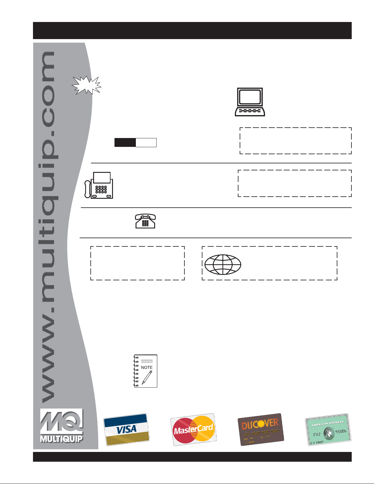
PARTS ORDERING PROCEDURES
Ordering parts has never been easier!
Choose from three easy options:
Effective:
January 1
st
, 2006
Best Deal!
Order via Internet (Dealers Only):
Order parts on-line using Multiquip’s SmartEquip website!
■
View Parts Diagrams
■
Order Parts
■
Print Specification Information
Goto www.multiquip.com and click on
Order Parts
to log in and save!
Order via Fax (Dealers Only):
All customers are welcome to order parts via Fax.
Domestic (US) Customers dial:
1-800-6-PARTS-7 (800-672-7877)
Non-Dealer Customers:
Contact your local Multiquip Dealer for
parts or call 800-427-1244 for help in
locating a dealer near you.
Order via Phone:
If you have an MQ Account, to obtain a
Username and Password, E-mail us at:
parts@multiquip.com.
To obtain an MQ Account, contact your
District Sales Manager for more information.
internet
Use the
on
Standard orders
and qualify for a 5% Discount
for all orders which include
complete part numbers.*
Fax
your order in and qualify for a 2% Discount
on
Standard orders
for all orders which include
complete part numbers.*
Domestic (US) Dealers Call:
1-800-427-1244
International Customers
their local Multiquip Representatives for
Parts Ordering information.
Note: Discounts Are Subject To Change
Note: Discounts Are Subject To Change
should contact
When ordering parts, please supply:
❒❒
❒
❒❒
Dealer Account Number
❒
❒❒
❒❒
❒
Dealer Name and Address
❒❒
❒❒
Shipping Address (if different than billing address)
❒
❒❒
❒❒
❒
Return Fax Number
❒❒
❒❒
❒
Applicable Model Number
❒❒
❒❒
❒
Quantity, Part Number and Description of Each Part
❒❒
All orders are treated as
Standard Orders
and will ship the same day if received prior
to 3PM PST.
www.multiquip.com
WE ACCEPT ALL MAJOR CREDIT CARDS!
R2000H RIDE-ON STATIC ROLLER — OPERATION & PARTS MANUAL — REV. #4 (07/24/08) — PAGE 5
Specify Preferred Method of Shipment:
❒❒
✓
UPS/Fed Ex
■
Priority One
■
Ground
■ Next Day
■
Second/Third Day
✓ DHL
✓
Tr u ck
Page 6

R2000H — SPECIFICATIONS (ROLLER)
thgieWyrD).gK726(.sbl283,1
thgieWtsallaBlluF).gK410,1(.sbl532,2
htgneLllarevO).mm458,1(.ni37
snoitacificepSrelloR0002R.1elbaT
htdiWllarevO).m
thgieHllarevO).mm592,1(.ni15
htdiWgnilloR
retemaiDlloR
ecnaraelCdnuorG
-HR
gnahrevO
yticapaCknaTretaW ).gK5.08sretil5.97(.sbl771snollag12
yticapaCslloRtnorF
yticapaClloRraeR ).gK491sretil391(.sbl724snollag15
m049(.ni73
).mm117(.ni82-tnorF
)mm318(.ni23-raeR
805(.ni02-tnorF
).mm
)mm016(.ni42-raeR
).mm38(.ni52.3-HR
).mm922(.ni9-HL
).mm38(.ni52.3
).mm44(.ni57.1-HL
).gK411sretil8.65+8.65(.sbl052snollag51+51
deepSlevarT)esreverdnadrawrof.xam(hpm6.5
aM)seerged51(%72
evirD
PAGE 6 —R2000H RIDE-ON STATIC ROLLER — OPERATION & PARTS MANUAL — REV. #4 (07/24/08)
tneidarGmumix
)edisnI(suidaRgninruT).mm002,3(.tf5.01
gnireetS)niahC(lacinahceM
ekarBgnikraPnoitautcalacinahcem-dnaB
metsySlacirtcelEdnuorg.gen,CDV21
epyTyrettaB42puorGeziS
snoisnemiDyrettaB ).mc8.71x8.71x5.32(.ni7x7x52.9
atsordyhnevirdtleb-V
llorraerotevird
sruoHpmA042G
niahcnoissimsnartcit
Page 7

R2000H — SPECIFICATIONS (ENGINE)
ledoM 2EAQ1K042XGADNOH
snoitacificepSenignE.2elbaT
epyT enignEenilosaGtfahSlatnoziroH,VHO,rednilyCelgniS,
ekortSXeroB
tnemecalpsiD )cc242(.ni-uc18.41
tuptuOxaM .M.P.R0063
yticapaCknaTleuF )sretil6(.lag.S.U95.1
leuF enilosaGelibomotuAdedaelnU
yticapaCliOebuL )sretil1.1(
lortnoCdeepS
dohteM
dohteMgnitratS tratScirtcelE
noisnemiD
)HxWxL(
ekorts4delooc-riA
.ni3.2x.ni9.2
)mm85xmm37(
/.P.H1.7
.tq.S.U61.1
epyTthgiew-ylFlagufirtneC
.61x9.61x0.41
.ni1
)mm014x034x553(
thgieWteNyrD )gK52(.sbl1.55
R2000H RIDE-ON STATIC ROLLER — OPERATION & PARTS MANUAL — REV. #4 (07/24/08) — PAGE 7
Page 8
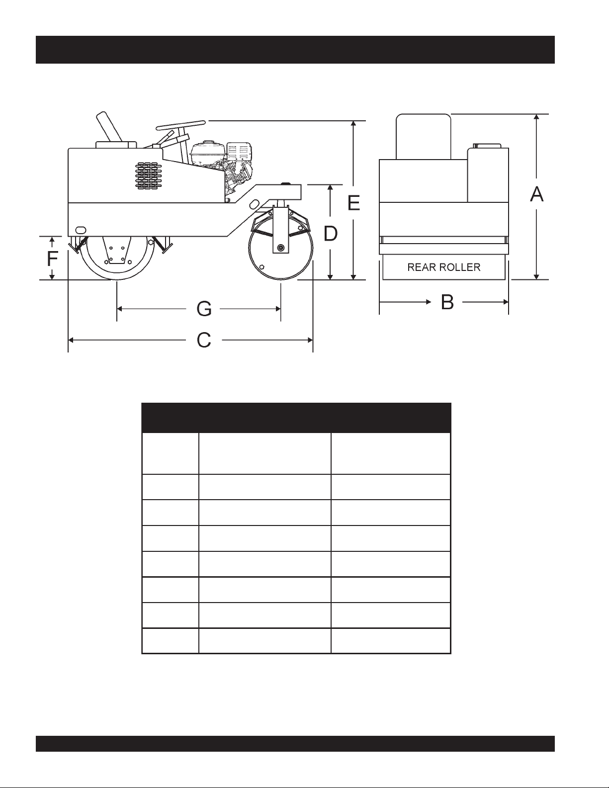
R2000H — DIMENSIONS
Figure 1. R2000H Roller Dimensions
SNOISNEMID.3ELBAT
.FER
NOITPIRCSED
RETTEL
AthgieHllarevO).mm5921(.ni15
BhtdiWllarevO).mm049(.ni73
ChtgneLllarevO)
DthgieHemarFtnorF).mm318(.ni23
EthgieHleehWgnireetS).mm9121(.ni84
FthgieHemarFrewoL).mm234(.ni71
GhtgneLesaBleehW).mm0721(.ni05
NOISNEMID
).MM(.NI
.mm4581(.ni37
PAGE 8 —R2000H RIDE-ON STATIC ROLLER — OPERATION & PARTS MANUAL — REV. #4 (07/24/08)
Page 9
R2000H — SAFETY MESSAGE ALERT SYMBOLS
FOR YOUR SAFETY AND THE SAFETY OF OTHERS!
Safety precautions should be followed at all times when
operating this equipment. Failure to read and understand the
Safety Messages and Operating Instructions could result in
injury to yourself and others.
This Operation and Parts Manual
has been developed to provide
NOTE
complete instructions for the safe
and efficient operation of the
Multiquip Model R2000H
Roller. Refer to the engine
manufacturer's instructions for
data relative to its safe operation.
Before using this roller, ensure
that the operating individual
has read and understands all
instructions in this manual.
Static
HAZARD SYMBOLS
SAFETY MESSAGE ALERT SYMBOLS
The three (3) Safety Messages shown below will inform you
about potential hazards that could injure you or others. The
Safety Messages specifically address the level of exposure to
the operator, and are preceded by one of three words: DANGER,
WARNING, or CAUTION.
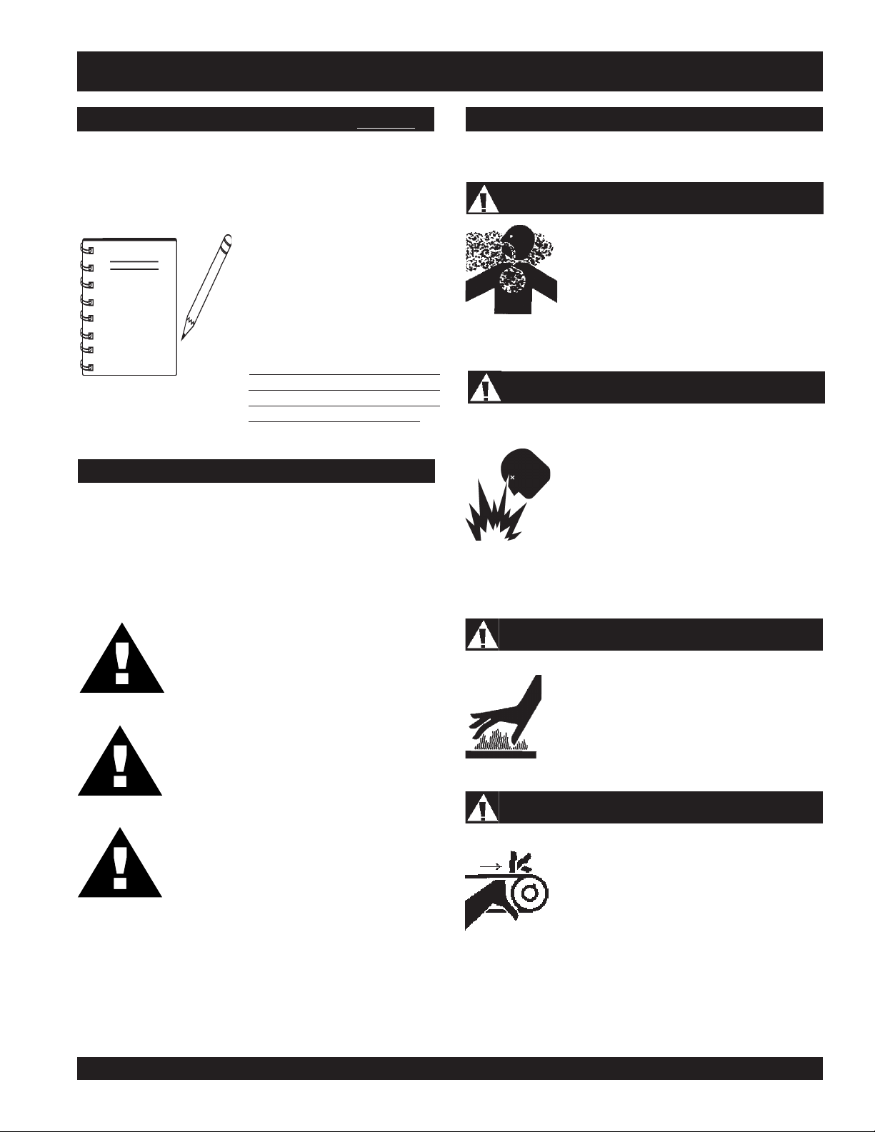
Lethal Exhaust Gases
Engine exhaust gases contain poisonous
carbon monoxide. This gas is colorless and
odorless, and can cause death if inhaled.
NEVER operate this equipment in a confined
area or enclosed structure that does not
provide ample free flow air.
Explosive Fuel
GASOLINE is extremely flammable, and its
vapors can cause an explosion if ignited. DO
NOT start the engine near spilled fuel or
combustible fluids. DO NOT fill the fuel tank
while the engine is running or hot. DO NOT
overfill tank, since spilled fuel could ignite if it
comes into contact with hot engine parts or
sparks from the ignition system. Store fuel in
approved containers, in well-ventilated areas
and away from sparks and flames. NEVER
use fuel as a cleaning agent.
DANGER: You WILL be KILLED or
SERIOUSLY injured if you do not follow
directions.
WARNING: You CAN be KILLED or
SERIOUSLY injured if you do not follow
directions.
CAUTION: You CAN be injured if you
do not follow directions.
Potential hazards associated with MQ R2000H vibration roller
operation will be referenced with Hazard Symbols which appear
throughout this manual, and will be referenced in conjunction
with Safety Message Alert Symbols.
Burn Hazards
Explosive Fuel
Engine components can generate extreme heat.
To prevent burns, DO NOT touch these areas
while the engine is running or immediately after
operations. Never operate the engine with heat
shields or heat guards removed.
Rotating Parts
NEVER operate equipment with covers, or
guards removed. Keep fingers, hands, hair and
clothing away from all moving parts to prevent
injury.
R2000H RIDE-ON STATIC ROLLER — OPERATION & PARTS MANUAL — REV. #4 (07/24/08) — PAGE 9
Page 10
R2000H — SAFETY MESSAGE ALERT SYMBOLS
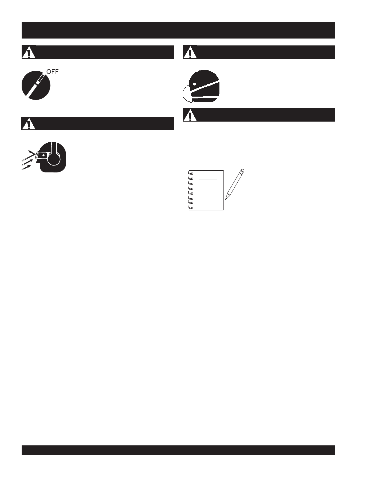
Accidental Starting
ALWAYS place the engine ON/OFF switch in
the OFF position, and remove the ignition key
when the machine is not in use.
Sight and Hearing hazard
ALWAYS wear approved eye and hearing
protection.
Respiratory Hazard
ALWAYS wear approved respiratory
protection.
Equipment Damage Messages
Other important messages are provided throughout this manual
to help prevent damage to your roller, other property, or the
surrounding environment.
This roller, other property, or the
surrounding environment could
NOTE
be damaged if you do not follow
instructions.
PAGE 10 —R2000H RIDE-ON STATIC ROLLER — OPERATION & PARTS MANUAL — REV. #4 (07/24/08)
Page 11
RULES FOR SAFE OPERATION
■
DANGER:
Failure to follow instructions in this manual may
lead to serious injury or even death! This
equipment is to be operated by trained and
qualified personnel only! This equipment is for
industrial use only.
The following safety guidelines should always be used when
operating the R2000H Roller:
GENERAL SAFETY
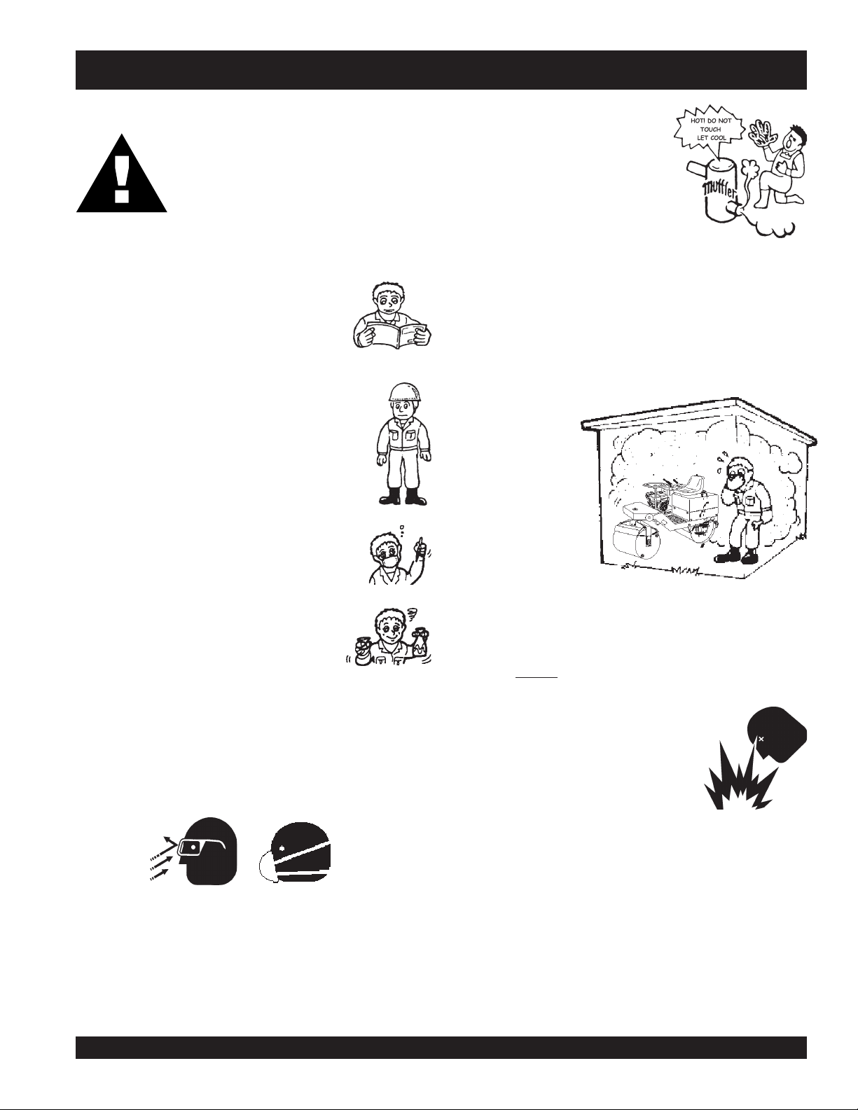
■
DO NOT operate or service this equipment before
reading this entire manual.
■
This equipment should not be operated by
persons under 18 years of age.
■
NEVER operate this equipment without proper
protective clothing, shatterproof glasses, steeltoed boots and other protective devices required
by the job.
■
NEVER operate this equipment when not feeling
well due to fatigue, illness or taking medicine.
NEVER touch the hot exhaust manifold,
muffler or cylinder. Allow these parts to
cool before servicing engine or pump.
■
High Temperatures – Allow the engine to cool before adding
fuel or performing service and maintenance functions. Contact
hot
with
■
The engine of this roller requires an adequate free flow of
cooling air. Never operate the roller in any enclosed or narrow
area where free flow of the air is restricted. If the air flow is
restricted it will
cause serious
damage to the roller
or engine and may
cause injury to
people and property.
Remember the
roller's engine gives
off DEADLY gases.
components can cause serious burns.
■
NEVER operate this equipment under the
influence or drugs or alcohol.
■
Whenever necessary, replace nameplate, operation and
safety decals when they become difficult read.
■
ALWAYS check the machine for loosened threads or bolts
before starting.
■
ALWAYS wear proper respiratory (mask) hearing and eye
protection equipment when operating the roller.
■
ALWAYS refuel in a well-ventilated area, away from sparks
and open flames.
■
ALWAYS use extreme caution when working with flammable
liquids. When refueling, stop the engine and allow it to cool.
DO NOT
could result from fuel vapors, or if fuel is spilled on a hot
engine.
■
NEVER operate the roller in an
explosive atmosphere or near
combustible materials. An explosion or
fire could result causing severe
smoke around or near the machine. Fire or explosion
bodily
harm or even death.
■
Topping-off to filler port is dangerous, as it tends to spill fuel.
■
Refer to the
technical questions or information.
■
NEVER use accessories or attachments, which are not
recommended by Multiquip for this equipment. Damage to
the equipment and/or injury to user may result.
■
Manufacturer does not assume responsibility for any accident
due to equipment modifications.
Honda Engine Owner's Manual
for engine
R2000H RIDE-ON STATIC ROLLER — OPERATION & PARTS MANUAL — REV. #4 (07/24/08) — PAGE 11
Page 12

■
NEVER Run engine without air cleaner. Severe engine
damage may occur.
■
ALWAYS read, understand, and follow procedures in
Operator’s Manual before attempting to operate equipment.
■
ALWAYS be sure the operator is familiar with proper safety
precautions and operations techniques before using roller.
■
ALWAYS store equipment properly when it is not being used.
Equipment should be stored in a clean, dry location out of the
reach of children.
■
DO NOT operate this roller with hydrostatic oil temperature
higher than 180 degrees fahrenheit.
■
NEVER leave the roller unattended, turn off engine and place
parking brake lever in upright position.
■
CAUTION must always be observed while servicing this roller.
Rotating parts can cause injury if contacted.
■
DO NOT leave roller with engine running.
■
If the roller must be stopped on an incline (grade), remove the
ignition key and
front
and
■
NEVER drive the roller on unshored trenches or near steep,
place chock blocks (not provided) under
rear
drums.
unsupported banks. The vibration caused by the roller could
cause a cave-in.
■
ALWAYS use extreme care when operating near obstructions,
on slippery surfaces, grades and side slopes.
■
ALWAYS wear slip resistant safety shoes or boots.
■
Unauthorized equipment modifications will void all
■
■
■
■
■
■
Maintenance Safety
■
the
■
■
■
■
■
warranties.
■
When working on slopes, avoid
sidehill travel
. Operate up
■
and down travel only. Remember, the danger of sliding on
and/or tripping on steep slopes is always present.
RULES FOR SAFE OPERATION
Start the roller only when seated in the operator’s position.
Check all hydraulic components and fittings for wear.
Before starting engine, ensure that there is smooth movement
of the travel lever, throttle and parking brake.
ALWAYS check
leakage before starting engine.
High Temperatures – Always stop engine and allow the
engine to cool before adding fuel, oil or performing service
and maintenance functions. Contact with
cause serious burns.
NEVER disconnect any
These devices are intended for operator safety. Disconnection
of these devices can cause severe injury, bodily harm or even
death! Disconnection of any of these devices will void all
warranties.
NEVER lubricate components or attempt service on a running
machine.
ALWAYS allow the machine a proper amount of time to cool
before servicing.
Keep the machinery in proper running condition.
Fix damage to the machine immediately and always replace
broken parts, or missing decals.
Dispose of hazardous waste properly. Examples of potentially
hazardous waste are used motor oil, fuel and fuel filters.
DO NOT use food or plastic containers to dispose of
hazardous waste.
DO NOT pour waste, oil or fuel directly onto the ground,
down a drain or into any water source.
hydraulic oil, engine oil
, and fuel levels for
hot
"emergency or safety devices"
components can
.
■
ALWAYS wear
■
When malfunctions occur, always remove the ignition key
and place a "
seat belts
.
DO NOT OPERATE
" sign in the operator's
seat.
■
If a malfunction occurs with the travel lever mechanism, speed
and direction will be impossible to control. Immediately stop
the roller and correct the problem.
■
If the steering system operates improperly, immediately stop
the engine and apply the parking brake.
■
In the event of hydraulic hose or line failure, promptly return
the travel lever to the “neutral” position, stop the engine and
set the parking brake.
PAGE 12 —R2000H RIDE-ON STATIC ROLLER — OPERATION & PARTS MANUAL — REV. #4 (07/24/08)
Page 13
RULES FOR SAFE OPERATION
Loading and Transporting
DANGER :
DANGER! ALWAYS LOAD AND UNLOAD
THE ROLLER ON LEVEL, HARD GROUND
OR PAVEMENT.
result from improper loading, lifting or
unloading. Use extreme caution!
■
The roller has an operating weight of approximately 2,063
lbs. (938 Kg). Use lifting equipment capable of lifting this
weight.
■
ALWAYS check the roller's lifting hooks. Before lifting or
transporting the roller, lock the frame with the locking bar that
is provided. Make sure the hooks are secure and tight before
lifting the machine.
■
When driving the roller onto a transporting vehicle or trailer,
use ramps or other suitable material of sufficient strength to
support the roller.
■
Remove mud, oil, ice, snow or any other slippery materials
from the ramps and bed of the vehicle to avoid accidents.
■
After loading, apply the parking brake.
■
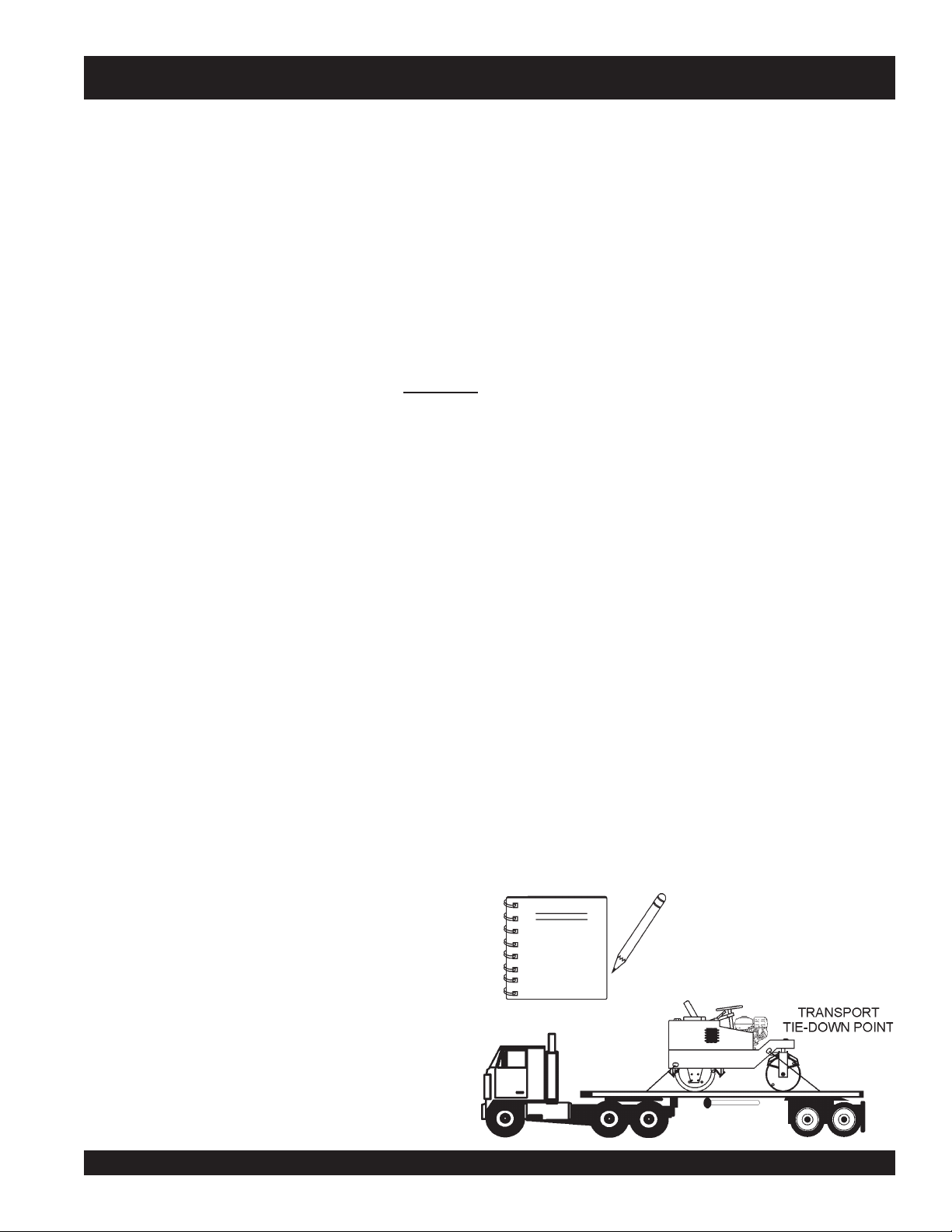
Use a chain, binders or other suitable means to firmly secure
the roller before transporting.
■
Only use the lifting points for the roller that are clearly marked
lifting point
as “
”.
Serious injury or death can
Emergencies
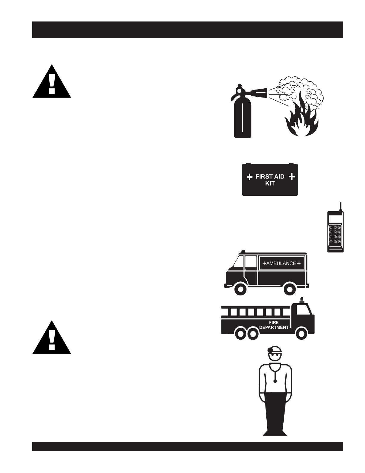
■
■
■
ALWAYS know the location of the nearest
ALWAYS know the location of the nearest and
In emergencies
nearest phone or
Also know the phone numbers of the nearest
ambulance, doctor
information will be invaluable in the case of an
emergency.
always
know the location of the
keep a phone on the job site
and
fire department
fire extinguisher
first aid kit
.
. This
.
.
■
NEVER apply chains through the articulating section of the
roller. The chain could cause damage by scoring the hydraulic
steering cylinder.
■
NEVER stand below roller when it is being lifted.
DANGER :
DO NOT allow personnel to
near any suspended machine
or death may result.
stand under
. Serious injury
or
R2000H RIDE-ON STATIC ROLLER — OPERATION & PARTS MANUAL — REV. #4 (07/24/08) — PAGE 13
Page 14
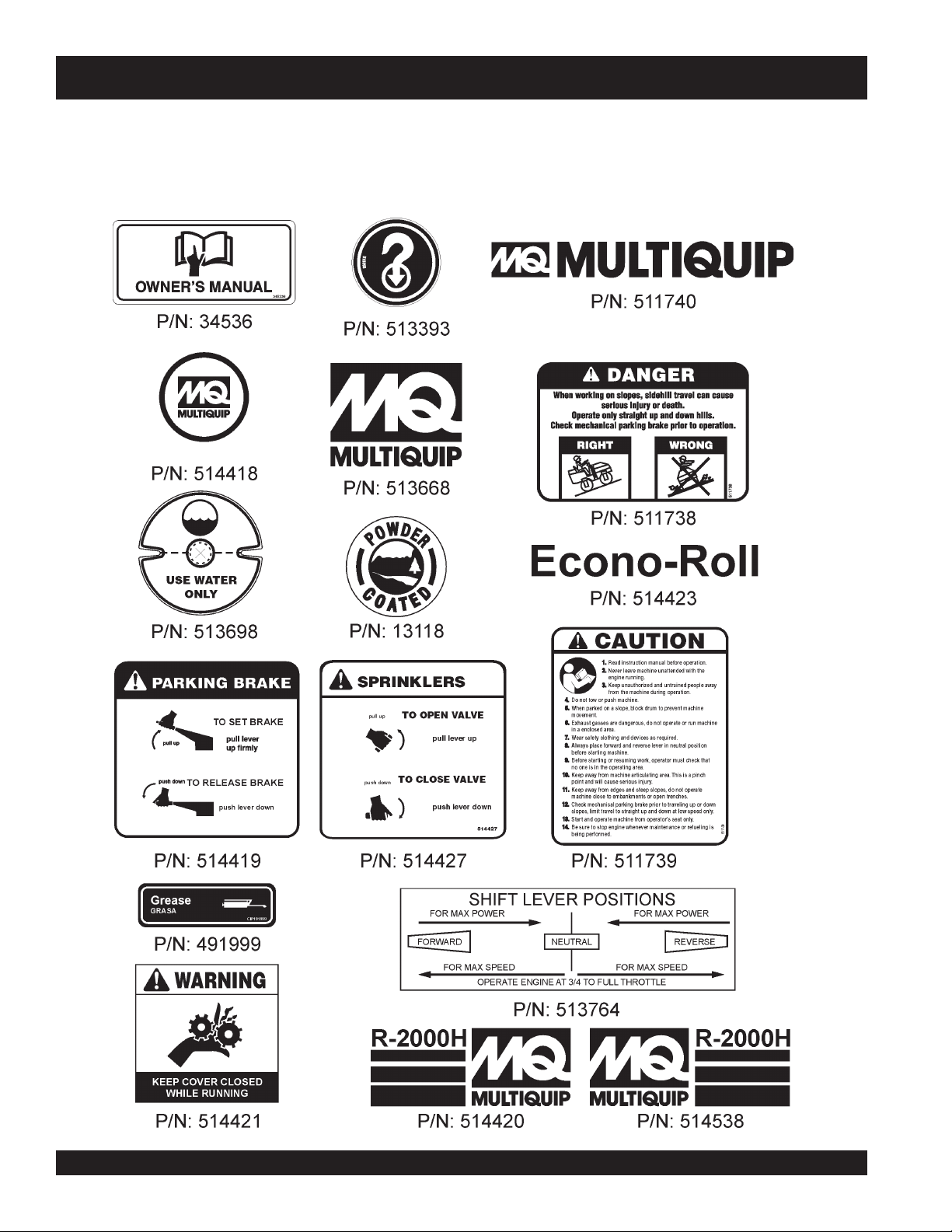
Machine Safety Decals
OPERATION AND SAFETY DECALS
The R2000H
information. The illustration below and on the next page shows these decals as they appear on the machine. Should any of these
decals become unreadable, replacements can be obtained from your dealer.
static roller
is equipped with a number of safety decals. These decals are provided for operator safety and maintenance
PAGE 14 —R2000H RIDE-ON STATIC ROLLER — OPERATION & PARTS MANUAL — REV. #4 (07/24/08)
Page 15
R2000H — GENERAL INFORMATION
The R2000H roller has been designed for asphalt application
and compaction of granular soils used in site preparation. Use
the machine only for the purpose intended and by experienced
personnel who understand this operating manual and all safety
decals. Typical applications for this roller are driveways, patch
work and road repairs.
POWER PLANT
The R2000H roller is powered by a Honda GX240K1QAE2, aircooled, gasoline engine rated at 7.1 hp @3,600 rpm. The engine
features a side-mounted muffler designed to direct engine
exhaust away from the operator. In the event of low oil, this engine
has a built in "
oil level reaches an unsafe operating level.
SPRINKLER SYSTEM
A 21 gallon (79.5 liters) water tank with a gravity feed spray bar
is provided for wetting the roll for asphalt pavement rolling.
The water system is fully adjustable from the operator’s position
by adjusting the valve in the floor.
Water can be added to the front and rear rollers. Thirty gallons
(250 lbs.) of water can be added to the front rollers, 51 gallons
(427 lbs.) to the rear roller.
oil alert system
" that will shut down if the engine
NEVER! stand under, or get onto the roller while it is being lifted
or moved.
ONLY! use approved certified lifting devices capable of lifting at
least 4,000 lbs. (1,814 Kg.).
When lifting of the roller is required, only use the provided
eyes
to lift the roller. Using other sections of the roller for lifting
purposes may cause severe damage to the roller.
DO NOT operate this roller on
Danger
CAUTION
CAUTION
CAUTION
Danger
slippery
or
wet
surfaces.
lifting
Before starting an asphalt rolling job, be sure all spray bar holes
are clear of dirt or foreign matter and are working. Always use
clean fresh water in the water tank. To prevent rust and foreign
debris from clogging the spray bar holes, drain and flush water
tank and spray bars every 30 days.
LIFTING THE ROLLER
When lifting of the roller is required, attach a suitable
hook or shackle to the
lifting points (4) are marked by a lifting hook decal. Make
sure the lifting device is capable of lifting 4,000 lbs. (1,814 Kg.).
lifting eye
of the roller. These
DANGER:
Before operating the roller, make sure that
personnel and obstacles are free from the
roller’s path. Serious injury or even death can
result!
The forward-reverse control lever operates the hydrostatic pump
which governs the roller speed and direction of travel. The speed
in which movement of this lever is made is directly related to the
amount of pressure that is applied to the travel lever in each
direction. Travel speed is infinitely variable from 0 to 4 mph. The
neutral position of this lever will cause the roller to stop.
This roller is
(ROPS). The possibility exists of the roller tipping over causing
severe bodily harm , even death, if side-side operation is used
(Figure 3). DO NOT use this roller for side to side applications.
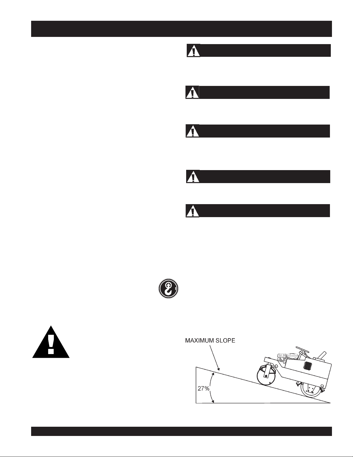
OPERATING ON SLOPES
Special care must be taken when operating the roller on hills or
slopes. There exist the possibility of serious injury to the operator
and severe damage to the roller in the event of a roll over.
ALWAYS operate the roller up and down hills rather than from
side to side. For safe operation hillside slopes should not exceed
15 degrees (27 % grade). See Figure 2 below.
not offered
Figure 2. Recommended Slope
with a
Rollover Protection Structure
R2000H RIDE-ON STATIC ROLLER — OPERATION & PARTS MANUAL — REV. #4 (07/24/08) — PAGE 15
Page 16
R2000H — GENERAL INFORMATION
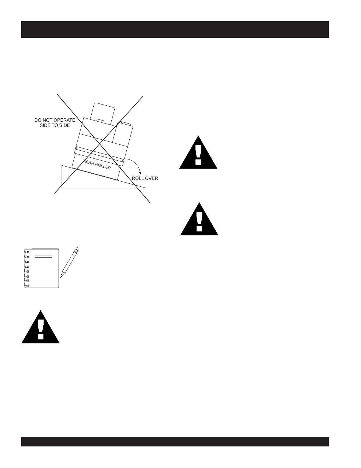
Tipping (Rollovers)
NEVER! operate the roller on side slopes (Figure 3). The
possibility exist that the roller could tip over (roll over), thus
causing bodily harm even death and serious damage to the
equipment.
In the event the roller does tip over, if at all possible, try to shut
down the engine by turning the ignition key to the
Extreme care must be taken to prevent damage to the engine.
When the roller has been tipped over, oil from the engine
crankcase can flow into the combustion chamber, which can
severely damage the engine the next time it is started.
IMMEDIATELY after a unit has tipped over upright the unit as
soon as possible to prevent oil from leaking into the combustion
chamber.
CAUTION:
WARNING:
Figure 3. Tipping (Rollover)
OFF
position.
To prevent damage to the engine after a
rollover, the roller must NOT be started.
NEVER start a roller after a rollover.
CONTACT your nearest authorized Multiquip
dealer for instructions or servicing.
This roller is intended to be used on flat
surfaces only. DO NOT use this roller near
open trenches, hollow spaces or rocks that
be below surface.
NOTE
DANGER:
NEVER! operate the roller on
slopes
causing injury to personnel and
severe damage to the equipment.
This roller is
Protection Structure
possibility exists of the roller tipping over
causing severe bodily harm , even death, if
side-side operation is used (Figure 3). DO
NOT use this roller for side to side
applications.
. The roller may tip over
not offered
with a
(ROPS). The
side
Rollover
PAGE 16 —R2000H RIDE-ON STATIC ROLLER — OPERATION & PARTS MANUAL — REV. #4 (07/24/08)
Page 17

NOTE PAGE
R2000H RIDE-ON STATIC ROLLER — OPERATION & PARTS MANUAL — REV. #4 (07/24/08) — PAGE 17
Page 18
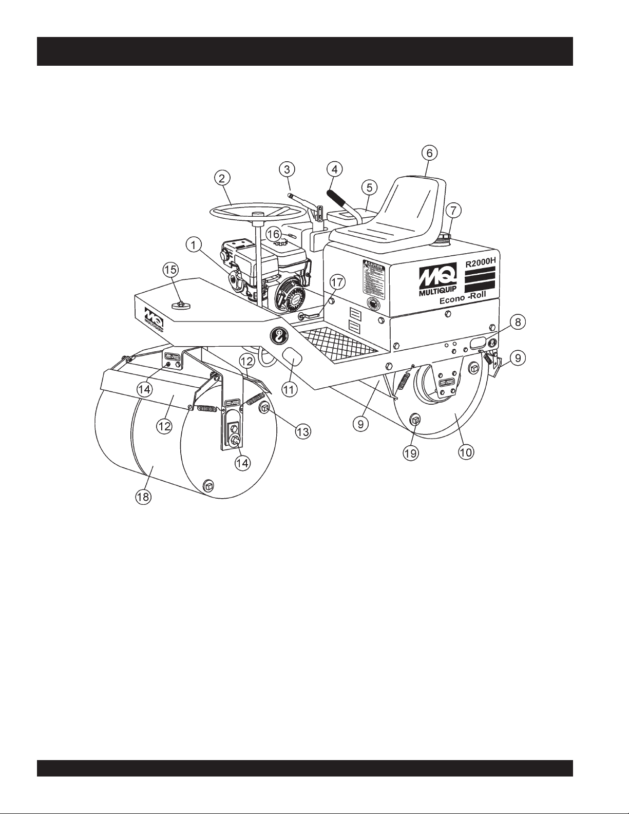
R2000H — ROLLER COMPONENTS
Figure 4. Roller Components
PAGE 18 —R2000H RIDE-ON STATIC ROLLER — OPERATION & PARTS MANUAL — REV. #4 (07/24/08)
Page 19
R2000H — ROLLER COMPONENTS
1. Engine – The MQ R2000H ride-on roller uses an 7.1 HP
Honda GX240K1QAE2 air cooled, 4-stroke, single cylinder
gasoline engine. This engine uses unleaded gasoline.
2. Steering Wheel — Use this wheel to steer the roller.
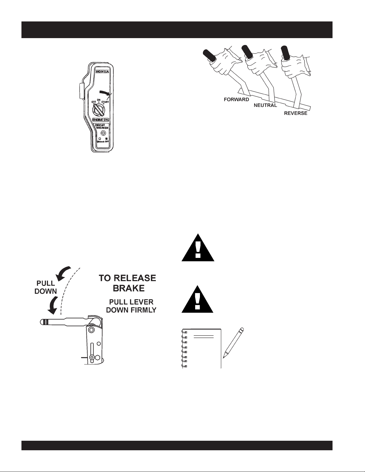
3. Parking Break Lever — Pull the lever upward to set the
parking break. To release the parking break, press and
hold the button on top of the lever and push lever downward.
4. Transmission Control Lever — Push the lever
to make the roller travel in a forward direction, pull the lever
backward
Maximum travel speed is 5.6 MPH (9.0 KPH). Center
position is neutral, no travel.
5. Documentation Box — Maintain and store
Operation, Parts, and Engine manuals in this box.
6. Operator's Seat —
of both front rear drum edges during
start the roller unless seated in the operator's seat.
7. Water Tank/Cap — Remove filler cap and fill with clean
fresh water. Water tank capacity is 21 gallons (79.5 liters).
If water level is low, add water as necessary.
8. Rear Lifting Point – Attach a crane or suitable lifting
device to this point when lifting of the roller is required.
9. Rear Scrapper – This adjustable rear scrapper blade
helps prevent the buildup of material between the drum
and frame.
10. Rear Roller – This roller is a 32-inch wide
with beveled edges (no vibration). The beveled edges
help prevent asphalt marring.
11. Front Lifting Point – Attach a crane or suitable lifting
device to this point when lifting of the roller is required.
12. Front Scrapper – This adjustable rear scrapper blade
helps prevent the buildup of material between the drum
and frame.
13. Front Roller Water Plug – Remove this plug to add
water (ballast) to the front drum. This plug is located on
each side of the split front roller.
14. Front Roller Zerk Fitting – Grease this fitting as
recommended in the maintenance section of this
manual.
15. Steering Zerk Fitting – Grease this fitting as
recommended in the maintenance section of this
manual.
to make the roller travel in a reverse direction.
A contoured seat that provides visibility
operation.
forward
at all times
NEVER!
steel drum
16. Access Panel – Lift this -panel to gain access to the
17. Sprinkler Valve Lever – A gravity feed spray bar is
18. Front Roller – This roller is a
19. Rear Roller Water Plug – Remove this plug to add
transmission assembly and battery.
A. Transmission – This roller uses a hydrostatic
pump which provides hydraulic pressure to the
hydraulic drive system. Fill the pump reservoir with
hydrostatic transmission fluid. Fill with Mobil 300,
GM Dextron B or Ford MCZ-41A type transmission
fluid.
Free Wheel Engagement Pin
The hydrostatic transmission is equipped with a free
wheel engagement pin, which, when actuated, allows
the oil to circulate freely within the roller, thereby
permitting the roller to be moved without the engine
running. This engagement pin is only to be used in
the event the roller is disabled.
This pin is located on the side of the hydrostatic
transmission underneath the acess cover. It is actuated
by pushing the pin inward and placing the locking
clip over the pin to keep it in place.
B. Battery – Provides +12VDC to the electrical
system. Replace only with recommended type
battery, see specification Table 1.
provided on the front and rear of the roller for the wetting
Pull
of the roll for asphalt pavement.
start
to
Push
drum
edges help prevent asphalt marring.
water (ballast) to the rear drum. This plug is located on
the chain-side of the roller. It is shown here for clarity
only.
NOTE
the flow of water to the gravity feed system.
the lever
with beveled edges (no vibration). The beveled
downward
to
Tie-Down Transport Points –
Attach a chain or suitable tie-down
device to these points when
transporting of the roller is
required.
upward on the lever
stop
the flow of water.
split
28-inch wide
steel
R2000H RIDE-ON STATIC ROLLER — OPERATION & PARTS MANUAL — REV. #4 (07/24/08) — PAGE 19
Page 20
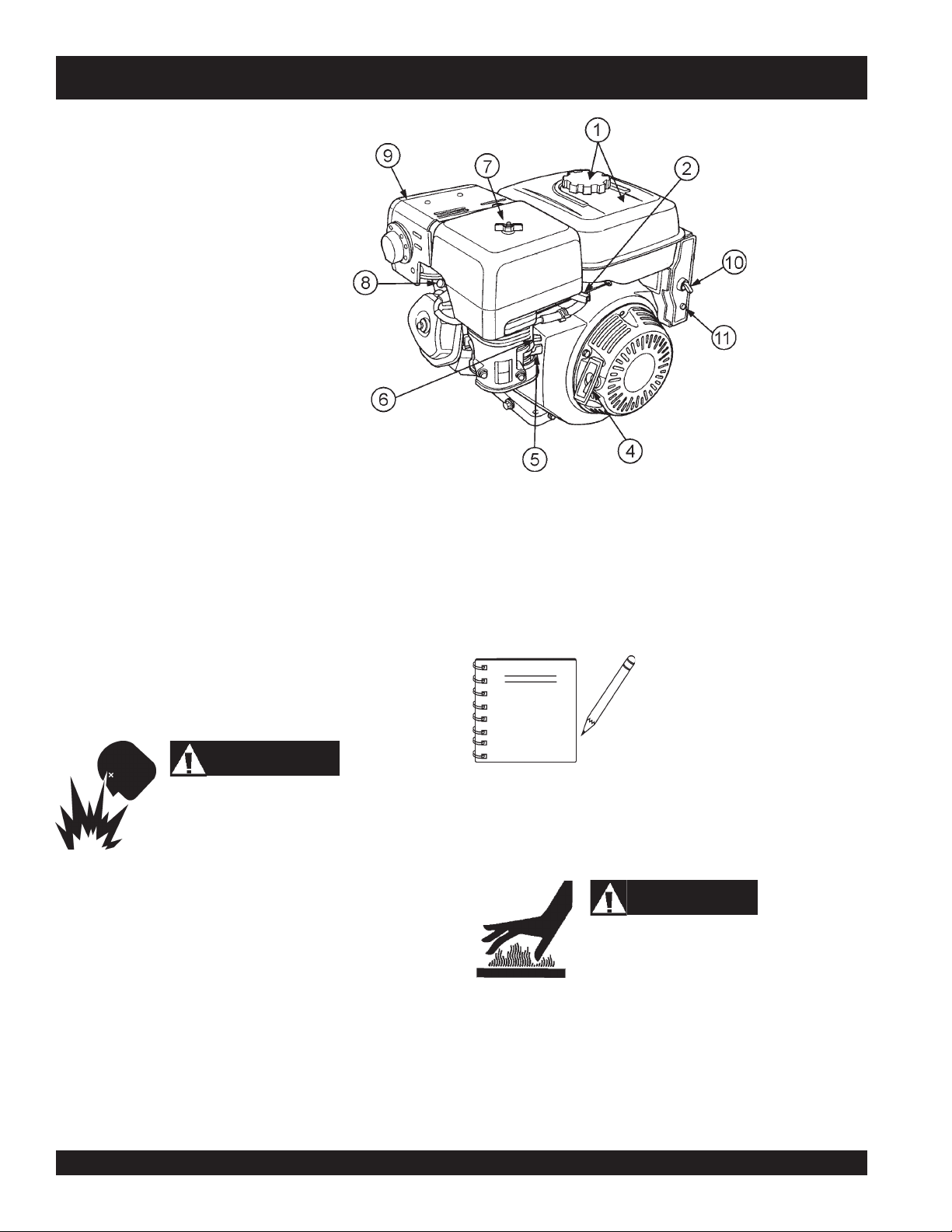
R2000H — ENGINE COMPONENTS
Figure 5. Engine Controls and Components
INITIAL SERVICING (ENGINE)
The engine (Figure 5) must be checked for proper lubrication and
filled with fuel prior to operation. Refer to the manufacturer's engine
manual for instructions and details of operation and servicing.
1. Fuel Filler Cap/Fuel tank – Remove this cap to add
unleaded gasoline to the fuel tank. Make sure cap is
tightened securely. DO NOT over fill. Fuel tank capacity is
1.59 gallons (6.0 liters). Use unleaded gasoline. For
additional information refer to Honda engine owner's
manual.
DANGER
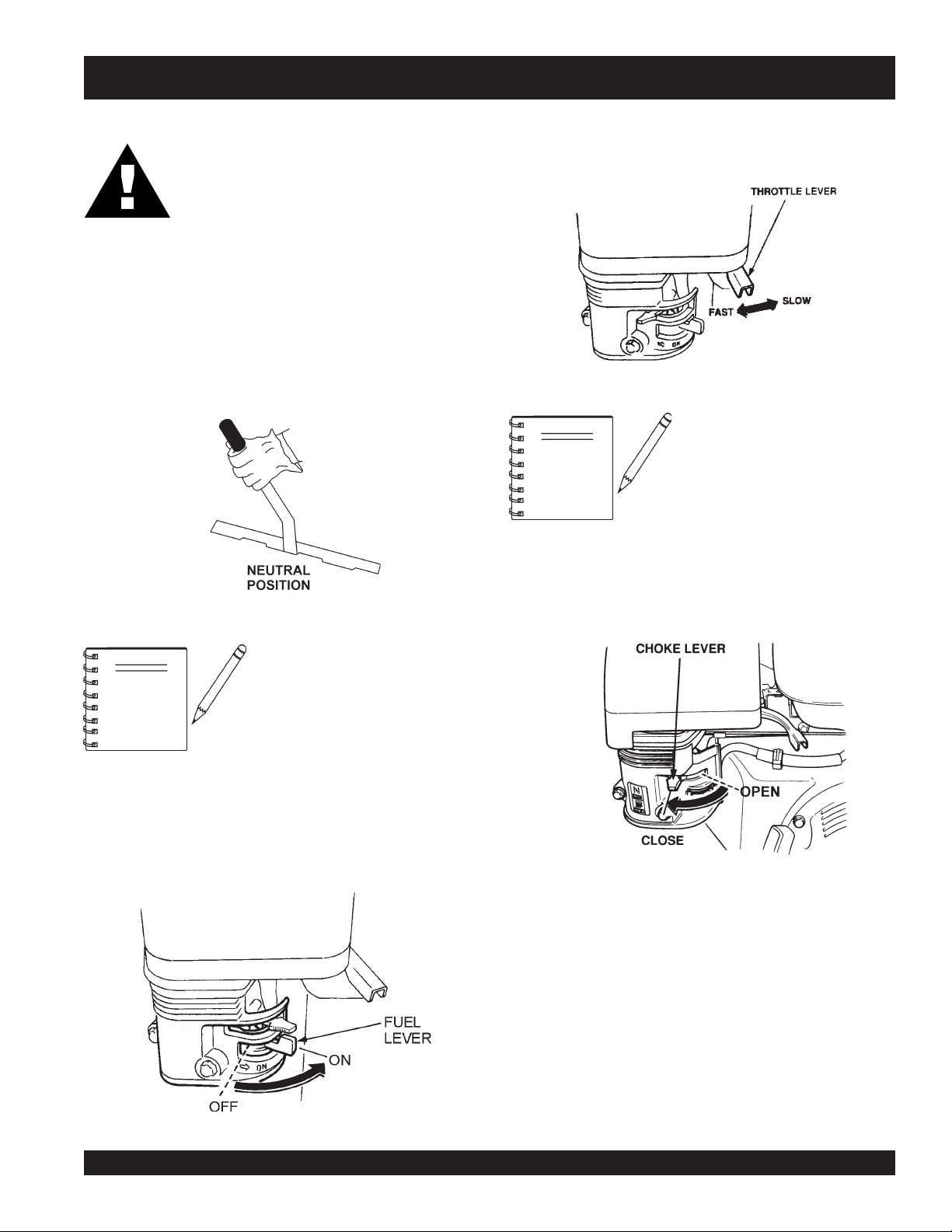
6. Choke Lever – Used in the starting of a cold engine, or in
cold weather conditions. The choke enriches the fuel
mixture.
7. Air Cleaner – Prevents dirt and other debris from entering
the air intake system. Remove wing-nut on top of air filter
cannister to gain access to filter element.
NOTE
Operating the engine without an air
filter, with a damaged air filter, or a
filter in need of replacement will allow
dirt to enter the engine, causing rapid
engine wear.
8. Spark Plug – Provides spark to the ignition system. Set
Adding fuel to the tank should be done only when
the engine is stopped and has had an opportunity
to cool down. In the event of a fuel spill, DO NOT
attempt to start the engine until the fuel residue has been completely
wiped up, and the area surrounding the engine is dry.
2. Throttle Lever – Used to adjust engine RPM speed (lever
advanced forward
FAST
).
3. Engine ON/OFF Switch – ON position permits engine
starting, OFF position stops engine operations.
4. Recoil Starter (pull rope) – Manual-starting method. Pull
the starter grip until resistance is felt, then pull briskly and
smoothly.
5. Fuel Valve Lever – OPEN to let fuel flow, CLOSE to stop
the flow of fuel.
PAGE 20 —R2000H RIDE-ON STATIC ROLLER — OPERATION & PARTS MANUAL — REV. #4 (07/24/08)
SLOW
, lever back toward operator
spark plug gap to 0.6 - 0.7 mm (0.028 - 0.031 inch) Clean
spark plug once a week.
9. Muffler – Used to reduce noise and emissions.
10. Ignition Switch– Use this switch to start and stop the
engine.
11. Circuit Breaker– Protects the battery charging circuit. See
Honda owner's manual for additional information.
WARNING
Engine components can generate extreme heat.
To prevent burns, DO NOT touch these areas
while the engine is running or immediately after
operating. NEVER operate the engine with the
muffler removed.
Page 21
R2000H — INSPECTION
CAUTION
NEVER operate the roller
in a confined area or
enclosed area structure
that does not provide
free flow of air
ample
ALWAYS wear approved eye and hearing
protection before operating the roller.
NEVER place hands or feet inside the guard
rings while the engine is running. ALWAYS
shut the engine down before performing any
kind of maintenance service on the roller.
Before Starting
1. Read safety instructions at the beginning of manual.
roller
2. Clean the
filter and carburetor.
3. Check the air filter for dirt and dust. If air filter is dirty, replace
air filter with a new one as required.
, removing dirt and dust, particularly the air
.
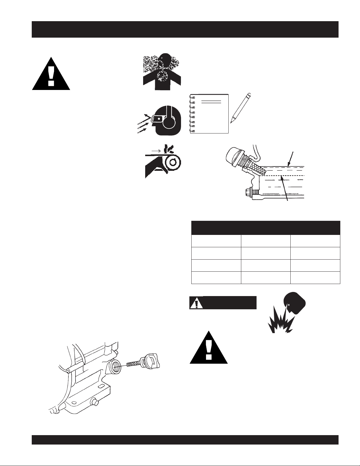
3. Insert and remove the dipstick without screwing it into the filler
neck. Check the oil level shown on the dipstick.
4. If the oil level is low (Figure 7), fill to the edge of the oil filler
hole with the recommended oil type (Table 4). Maximum oil
capacity is 400 cc.
Reference manufacturer engine
NOTE
Figure 7 Engine Oil Dipstick (Oil Level)
manual for specific servicing
instructions.
epyTliO.4elbaT
nosaeS erutarepmeT epyTliO
4. Check carburetor for external dirt and dust. Clean with dry
compressed air.
5. Check fastening nuts and bolts for tightness.
Engine Oil Check
Explosive Fuel
1. To check the engine oil level, place the roller on secure level
ground with the engine stopped.
2. Remove the filler dipstick from the engine oil filler hole
(Figure 6) and wipe it clean.
Figure 6. Engine Oil Dipstick (Removal)
CAUTION
Fuel Check
1. Remove the gasoline cap located on top of fuel tank.
2. Visually inspect to see if fuel level is low. If fuel is low, replenish
with unleaded fuel.
3. When refueling, be sure to use a strainer for filtration. DO
NOT top-off fuel. Wipe up any spilled fuel.
remmuS rehgiHroC°52 03-W01EAS
llaF/gnirpS C°01~C°52 02/03-W01EAS
retniW rewoLroC°0 01-W01EAS
Motor fuels are highly flammable and can be
dangerous if mishandled. DO NOT smoke
while refueling. DO NOT attempt to refuel the
roller if the engine is
hot! or running
.
R2000H RIDE-ON STATIC ROLLER — OPERATION & PARTS MANUAL — REV. #4 (07/24/08) — PAGE 21
Page 22
R2000H — INSPECTION
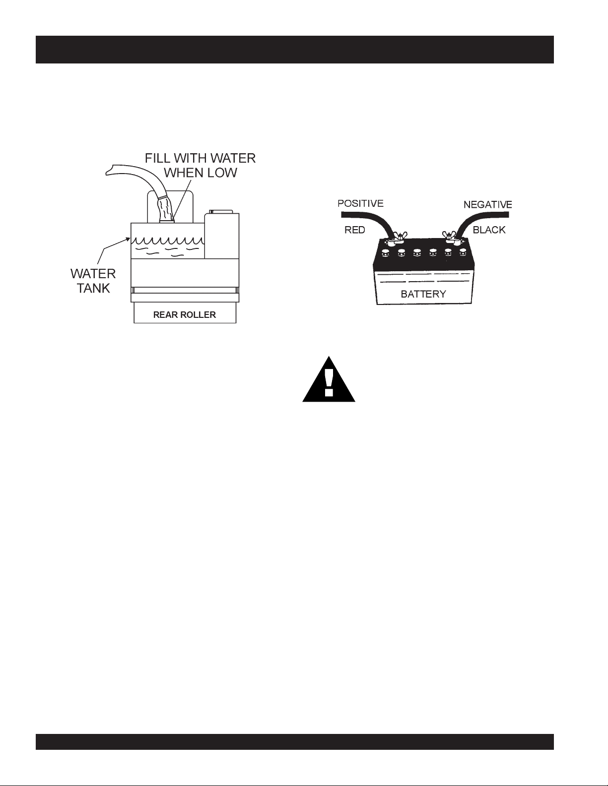
Water System Check
1. Check the water tank, located under the operator's seat, to
see if filled (Figure 8). Add water if necessary. The water
tank has a capacity of approximately 21 gallons (79.5 liters).
Figure 8. Water Tank Check
2. Water can also be added to the front and rear rollers. To fill,
remove pipe plug from the roller side plate and position
roller so that the hole is at the top. The right side cover must
be removed to fill the rear roller. Replace plugs and side
cover after filling. Thirty gallons (250 lbs.) of water can be
added to the front rollers and 51 gallons (427 lbs.) of water
can be added to the rear roller.
Battery Check
A 12-volt DC battery (Figure 9) is shipped dry, and will require a
proper electrolyte level for operation.
ALWAYS be sure that the battery cables are properly
connected to the battery terminals as shown below. Generally
RED
the
the battery, and the BLACK cable will be connected to the
negative terminal of the battery.
WARNING
cable will be connected to the positive terminal of
Figure 9. Battery
If the battery cables are connected
incorrectly, electrical damage will occur
causing damage to the roller's electrical
circuits. Pay close attention to the polarity
of the battery when connecting the battery.
3. Protect water from freezing by adding antifreeze or draining
water tank when not in use. Use only clean water in water
tank.
PAGE 22 —R2000H RIDE-ON STATIC ROLLER — OPERATION & PARTS MANUAL — REV. #4 (07/24/08)
Page 23
R2000H — INITIAL START-UP
CAUTION:
DO NOT attempt to operate the roller until the
Safety, General Information and Inspection
sections have been read and understood.
1. Sit down in the operator's seat.
2. Before starting engine, make sure the immediate area is free
of obstructions and debris that may lay in the roller's path.
3. Make sure that the roller's transmission control lever (Figure
10) is placed in the
neutral position
.
2 Rotate the
and
set to ensure optimum operating speeds.
NOTE
throttle lever
slow
for starting. The engine governor speed is factory
Figure 12. Throttle Lever
(Figure 12) halfway between
The CLOSED position of the
choke lever enriches the fuel
mixture for starting a COLD engine.
The OPEN position provides the
correct fuel mixture for normal
operation after starting, and for
restarting a warm engine.
fast
Figure 10. Transmission Control Lever
NOTE
Starting the Engine
1. Place the engine
position.
fuel valve lever
NEVER operate the roller with the
access cover open. Keeping the
cover closed will prevent dirt and
debris from entering into the
transmission and drivetrain
assemblies. ALWAYS keep the
access cover closed for normal
operation.
(Figure 11) to the "ON"
3. Place the
position.
Choke Lever
(Figure 13 in the "
Figure 13. Choke Lever
CLOSED
"
Figure 11. Engine Fuel Valve Lever
R2000H RIDE-ON STATIC ROLLER — OPERATION & PARTS MANUAL — REV. #4 (07/24/08) — PAGE 23
Page 24
4. Insert the ignition key into the ignition (Figure 14), place key
start
in the
5. If the engine does not start, repeat steps 1 through 4 or consult
the troubleshooting guide contained in this manual.
6. Let the engine warm for 3 to 5 minutes before using roller.
Check for fuel and oil leaks, and noises that would associate with a loose guard and/or covers.
7. If necessary return the choke knob to the full
position.
OPERATION
1. Release the parking brake by pushing down on the parking
brake lever.
position, when engine starts release key.
Figure 14. Ignition Switch
3. The speed of the roller is directly proportional to the amount
of pressure being applied to the lever in each direction. Travel
speed is between 0 and 4 mph (6.4 kph). The transmission
control lever may be moved forward or reverse at any engine
speed. However, it should not be moved rapidly as damage
to the drive train may result.
4. Further adjustment of travel speed can be made by changing
engine throttle setting. Maximum speed is attained with
maximum engine speed and full forward or reverse lever
position. Maximum power is attained with lever just out of
neutral position and maximum engine speed
OPEN
WARNING
R2000H — OPERATION
Figure 15. Traveling Forward
Transmission control lever must be in neutral
position when starting engine. NEVER engage
transmission abruptly because this places
unnecessary high loads on all drive line
components.
2. To make the roller move in a
transmission control lever forward as shown in Figure 15.
Make sure lever is securely place into notch.
PAGE 24 —R2000H RIDE-ON STATIC ROLLER — OPERATION & PARTS MANUAL — REV. #4 (07/24/08)
forward direction
, move the
WARNING
The
roller in the "
transmission system will not hold the roller in a
"stopped" condition.
NOTE
parking brake
To
transmission control lever toward
the
cannot be slowed or stopped
using the hydraulic braking system, use the
slow and then stop the roller.
must be used to hold the
stopped
slow
or
neutral position
" condition. The
stop
roller, move the
. If roller still
parking brake
to
Page 25
Water Sprinklers Control
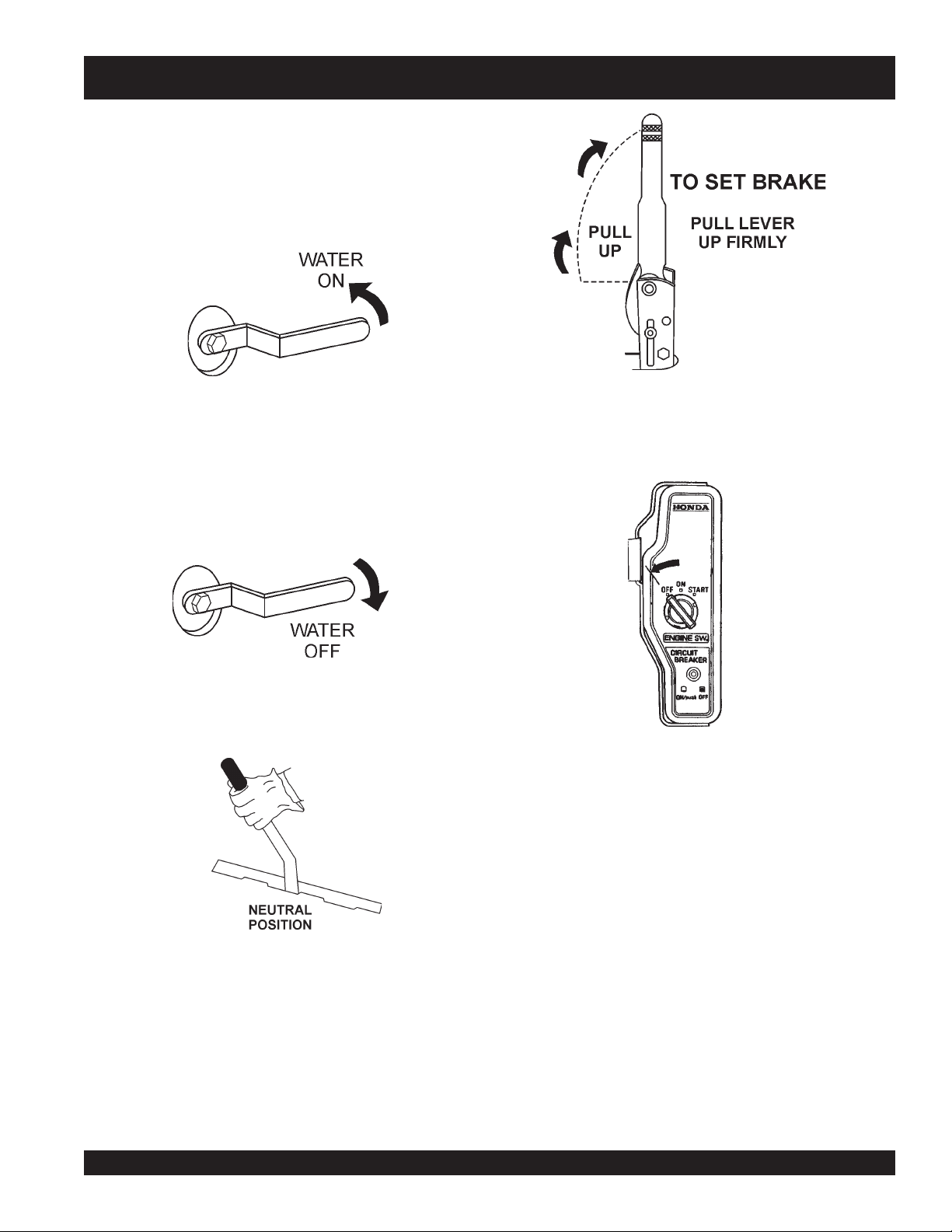
1. If the application requires the wetting of a surface, open
water valve
the
(Figure 16) to spread the proper amount of water onto the
roller drum at the desired rate that will wet both the front
and rear rollers.
located at the bottom of the roller floor
R2000H — OPERATION
Figure 16. Water Sprinkler Valve (ON)
Normal Shut-Down
1. Place the engine throttle lever in the idle position. Let the
engine idle for 3-5 minutes.
2. If the water valve is open, close it (Figure17)
Figure 17. Water Sprinkler Valve (OFF)
3.
Place
position
the transmission lever (Figure 18) in the
.
neutral
5. Turn the ignition key (Figure X) to the OFF position remove
key. Store key in a safe place.
6. Place the engine
position.
7. To prevent the roller from moving, place chock blocks under
each roller drum
Figure 19. Parking Brake Lever (Set)
Figure 20. Ignition Switch (OFF)
fuel valve lever
(Figure 20) in the OFF
Figure 18. Transmission Control Lever (Neutral)
4.
Place
the parking brake lever (Figure 19) in the
This will lock the rear roller drum in place, and prevent the
roller from moving. Whenever the operator's seat is vacated,
place the transmission lever in neutral, and set the parking
brake
R2000H RIDE-ON STATIC ROLLER — OPERATION & PARTS MANUAL — REV. #4 (07/24/08) — PAGE 25
set position
.
8. Clean the entire roller with warm water and mild soap. Pay
close attention to the scrapper bar and spray bar holes,
making sure that no dirt or debris is present. Dirt and debris
can cause the sprinkler system to get clogged.
Emergency Shut-Down
1. Turn the ignition key (Figure20) to the OFF position.
2. Place the engine
position.
fuel valve lever
(Figure 11) in the OFF
Page 26
R2000H — MAINTENANCE
Read carefully and follow the maintenance instructions in this
Hydrostatic Transmission
section. Always check the engine and transmission lubrication
before using the roller.
WARNING
1. Even minute amounts of foreign matter will cause major
damage. If the reservoir screen is damaged, it must be
replaced immediately.
Before servicing or performing maintenance,
off
make sure that the engine is
brake is
in the
disconnected
on
, the transmission control lever is
neutral
position, and the spark plug is
and secured away from the
, the parking
spark plug.
Lubrication
Refer to the lubrication chart below for proper lubrication of roller.
2. The fluid will last under normal operating conditions, for the
life of the transmission. If overheating or water contamination
occurs, the oil will change from its normal reddish color to
black or milky and must be replaced.
3. To drain the fluid, remove the plastic reservoir and the 3/816 hex head vent-plug from the top of the cast iron body.
CAUTION
Follow the engine's manufacturer manual for engine lubrication.
TRAHCNOITACIRBUL0002R.5ELBAT
METIEPYTLIOYCNEUQERF
citatsordyH
noissimsnarT
:nartyH.H.I
BnortxeD
ts
.kram
4. To refill, reassemble the hex head vent-plug and the plastic
tsriferofebyliadkcehC
"dloc"taniatniaM.tra
reservoir to the transmission. Refill through the reservoir with
clean fluid. With the transmission control lever in full forward
or reverse position, rotate the input pulley several times to
flush the internal mechanism of the transmission and re-
elxAtnorF
PMesaerGliboM
tnelaviuqero
ylkeeW
drain. Refill through the reservoir with an approved
transmission fluid.
The threads connecting the reservoir to the
aluminum body are left-handed. Turn
transmission upside down to drain.
toviPrelloRtnorF
eldnipS
gnireetSrelloRtnorF
eldnipS
sgniraeBrelloRraeR
sniahCevirD
enoN
PMesaerGliboM
tnelaviuqero
PMesaerGliboM
tnelaviuqero
detacirbul
W01EAS
)naelcpeek(
ylkeeW
ylkeeW
emitefilerasgniraeB.dedeen
yadaecnoylgnirapS
5. Prior to running the roller, the transmission fluid level should
not be above the cold mark. Overfilling reduces the expansion are in the reservoir and fluid will spill out at operating
temperatures.
6. Proper cooling is essential to both the performance and life
of the transmission. Cooling is dependent on the fan and the
fins on the body. Keep the fan tightened and replace it if the
blades become broken. Keep the cooling fins clean.
WARNING
Cleaning the transmission with high pressure
water spray or live steam may force water into
the reservoir. A few drops of water in the system
will result in excessive oil expansion, loss of oil
through the vent hole in the reservoir, and a
loss of power at operating temperature. A shield
or cover should be placed over the reservoir
cover during cleaning operation or in other
situations where water maybe introduced into
the unit.
PAGE 26 —R2000H RIDE-ON STATIC ROLLER — OPERATION & PARTS MANUAL — REV. #4 (07/24/08)
Page 27
R2000H — MAINTENANCE
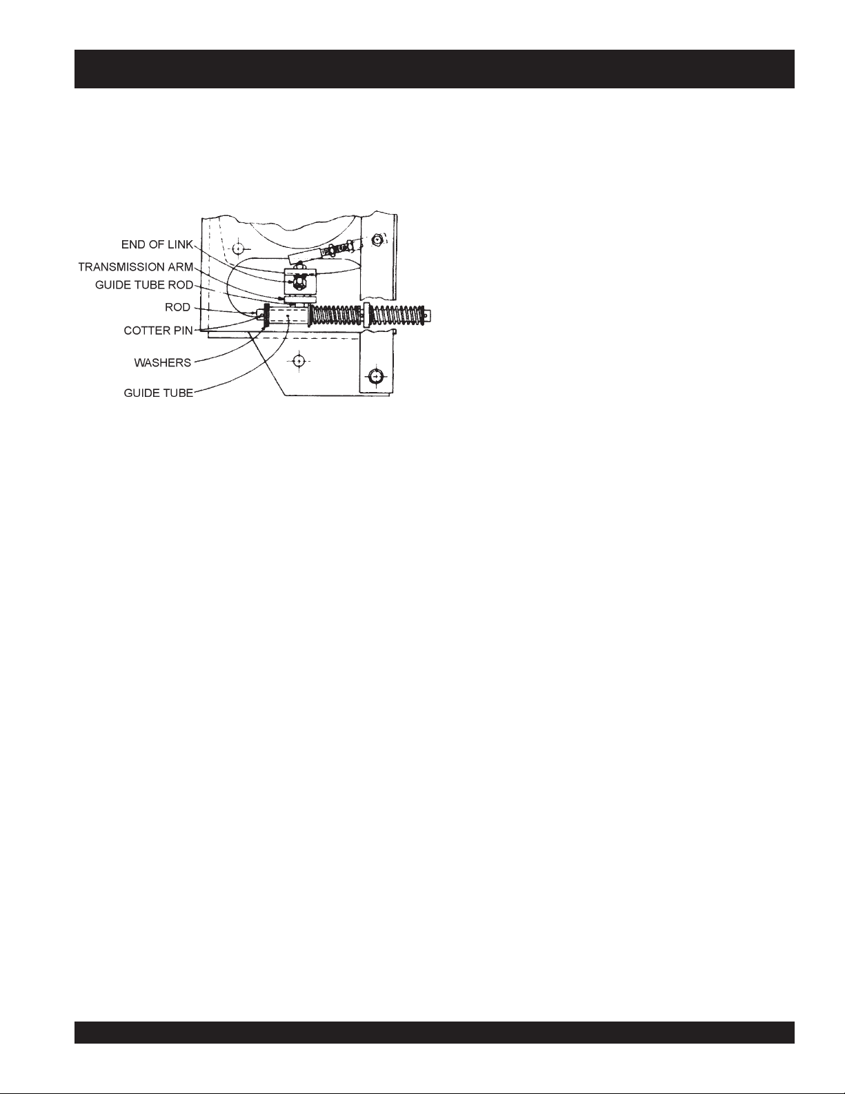
Transmission Control Lever Adjustment
If the roller tends to creep when the control lever is in neutral,
perform the following. Refer to Figure 21 for location of components.
Figure 21. Control Lever Adjustment Points
1. Place the unit where there is ample clearance fore and aft.
2. Open the cover, place the control lever to neutral position,
and remove cotter pin from rod.
3. Start engine and allow to run at idle speed.
4. Move control lever in reverse until roller just starts to move
backwards.
Brake Adjustment
1. The brake should be adjusted so that it takes 70 ± 5 lbs. of
force applied at the end of the lever to fully actuate it.
2. To adjust brake, turn the knob located at the top of the brake
lever clockwise (toward the operator) to tighten the brake.
3. Turn the knob counterclockwise (away from the operator) to
loosen the brake.
Steering Adjustment
1. The roller chain of the steering mechanism must be kept
clean, lightly oiled and properly tensioned.
2. Adjust the turnbuckle to allow 1/16" deflection to the slack
side of the chain when in the straight position.
Drive Chains
1. The drive chains must be kept clean, lightly-oiled, and
properly tensioned.
2. When wear of the side bars, rollers or sprockets become
noticeable, they should be replaced promptly.
3. Clean all dirt from the chain with solvent and re-oil lightly.
Drive Chains Tension Adjustment
5. Carefully hold the control lever in place and turn the engine
off.
6. Without disturbing setting of control lever/transmission arm,
add washers on rod between cotter pin hole and grid tube
and replace cotter pin.
7. Return control lever to neutral position.
8. Check position of guide tube rod in arm slot. If not centered,
remove end of link from arm, loosen lock nuts, adjust length
by screwing ends in or out until ball stud drops in arm in
centered position.
9. Tighten all nuts.
10. Restart engine and make sure transmission output sprocket
does not move, at all engine speeds.
1. Move the roller slowly in the reverse direction until the slack
side of the chain is toward the rear of the roller.
2. Put the control lever in the neutral position and shut the
engine off and apply parking brake.
3. Loosen the two bolts that hold the idler plate forward (into the
chain) using a pry bar.
4. Retighten the two mounting bolts.
5. Start the engine and move the roller in the forward direction,
5 to 10 feet.
6. Move the control lever to the neutral position and turn the
engine off.
7. Proper chain tension is approximately 0.2 to 0.4-inch deflection with approximately 5 lbs. of force applied to the center of
the span between the sprockets toward the front of the roller.
8. If the tension is still incorrect, readjust.
R2000H RIDE-ON STATIC ROLLER — OPERATION & PARTS MANUAL — REV. #4 (07/24/08) — PAGE 27
Page 28

R2000H — MAINTENANCE
Transmission V-Belt Adjustment
1. Keep pulleys clean and properly aligned using a straight
edge. Correct belt tension is essential for the transmission to
work properly and efficiently, and for the longevity of the belt.
2. Use a belt tension tester to check the belt tension.
3. Apply the load to the V-belt at the center of the span between
the pulleys. The belt deflection should be approximately 1/4"
with 3 1/2 lbs. to 4 lbs. load.
CAUTION
DO NOT overtighten the V-belt. This will cause
excessive strain on the transmission bearings,
resulting in transmission failure.
Scrapers, Cocoa Mats, and Sprinkler Bars
1. Keep roller scraper bars clean. Replace any broken or
stretched spring. Prevent accumulation of tar or debris around
pivot area.
3. ALWAYS keep the battery charged. If the battery is not
charged a buildup of combustible gas will occur.
4. ALWAYS keep battery charging and cables in good
working condition. Repair or replace all worn cables.
5. ALWAYS recharge the battery in an vented air
environment, to avoid risk of a dangerous concentration
of combustible gases.
6. ALWAYS wear eye protection and rubber gloves, since
the battery contains sulfuric acid which burns skin and
eats through clothing.
7. ALWAYS recharge the battery in an vented air
environment, to avoid risk of a dangerous concentration
of combustible gases.
8. In case the battery liquid (dilute sulfuric acid) comes in
contact with
immediately with plenty of water.
9. In case the battery liquid (dilute sulfuric acid) comes in
contact with your eyes, rinse eyes immediately with
plenty of water, then contact the nearest doctor or hospital,
and seek medical attention.
clothing or skin
, rinse skin or clothing
2. Remove and replace the cocoa mats when badly worn by
loosening the screws holding them in place. Remove the side
panel first to replace the rear mats.
3. Fill the water tank through the large cap on the top rear. Use
only clean water or the valve, hoses, and sprinkler bars may
become clogged.
Battery
The battery contains acids that can cause
injury to the eyes and skin. To avoid eye
irritation,
well insulated gloves when picking up the
battery. Use the following guidelines when
handling the battery:
1. DO NOT drop the battery. There is the possibility of risk
2. DO NOT expose the battery to open
always
that the battery may explode.
flames, sparks, cigarettes etc. The
battery contains combustible gases
and liquids. If these gases and
liquids come in contact with a flame
or spark, an explosion could occur.
wear safety glasses. Use
CAUTION:
z
Check the battery regularly and make sure that each
electrolyte level is to the bottom of the vent well
(Figure 22). If necessary add only distilled water in a
well-ventilated area.
If your clothing or skin comes in contact with
the battery acid,
running water and get medical attention.
Figure 22. Battery Fluid Levels
immediately
wash off with
PAGE 28 —R2000H RIDE-ON STATIC ROLLER — OPERATION & PARTS MANUAL — REV. #4 (07/24/08)
Page 29

R2000H — PREPARATION FOR LONG -TERM STORAGE
Roller Storage
For storage of the roller for over 30 days, the following is
recommended:
z
Drain the fuel tank completely, or add STA-BIL to the
fuel.
z
Run the engine until the fuel in the injection system is
completely consumed.
z
Completely drain used oil from the engine crankcase
and fill with fresh clean oil, then follow the procedures
described in the engine manual for engine storage.
z
Drain water tank
z
Clean the entire roller and engine compartment.
z
Remove battery and store it in cool dry place.
z
Cover the roller and place it a clean dry area, that is
protected from harsh elements.
z
Remove ignition key, and store in a safe place.
R2000H RIDE-ON STATIC ROLLER — OPERATION & PARTS MANUAL — REV. #4 (07/24/08) — PAGE 29
Page 30

R2000H — TROUBLESHOOTING (ROLLER)
GNITOOHSELBUORTRELLOR.6ELBAT
MOTPMYS MELBORPELBISSOP NOITULOS
?nievlavpmuD .evlavpmudtuolluP
esreveR
rewoPwoL
llitStupnIhtiw
egakaeLliO
rodrawroFoGt'noWrelloR
?tlebgnippilS .tlebnethgiT
?)citatsordyh(
tfahStupnIetatoRtonnaC ?noissimsnartdegamaD .relaedeeS
tfahStuptuOetatoRotelbA
?liowoL .liolliF
?egallipS .ylluferaclliF
?)citatsordyh(diulfwoL .diulfhtiwlliF
?tlebnekorbroesooL .yrassecenfiecalperrotlebnethgiT
?egaknillortnocnekorB egaknillortnocriapeR
?ylreporpgninnurtonenignE .launamdnagnitoohselbuortenigneotrefeR
?)citatsordyh(noissimsnartniretaW .ecalperdnaegruP
detaehrevonoissimsnarT
?noissimsnartdegamaD .relaedeeS
?mrawnehwnoisnapxE .dlocnehwllifrevotonoD
?riovreserdegamaD .riovreserecalpeR
?steksag,revoc,tlobtnevesooL .nethgiT
.gnittesdeepsrewoltaetarepo,nafnekorbecalper,snifnaelC
?laestfahslortnocdaB .laesecalpeR
?laestfahsdaB .relaedeeS
PAGE 30 —R2000H RIDE-ON STATIC ROLLER — OPERATION & PARTS MANUAL — REV. #4 (07/24/08)
Page 31

R2000H — TROUBLESHOOTING (ENGINE)
MOTPMYS MELBORPELBISSOP NOITULOS
tratsottluciffiD
GNITOOHSELBUORTENIGNE.7ELBAT
.)elbacnoisnet
rewoP(.etingiton TON taelbaliava
.)elbacnoisnethgih
noisserpmoc(setingi )lamron .
noisserpmoc(setingi wol .)
lliwgulpkrapstubelbaliavasileuF
hgihtaelbaliavarewoP(.etingiton
?srotalusni
lliwgulpkrapstubelbaliavasileuF
gulpkrapsdnaelbaliavasileuF
?stisoped
?)tsud
gulpkrapsdnaelbaliavasileuF
?nrowrednilyC .rednilycecalpeR
yrotcafsitastonnoitarepO
elbaliavarewophguonetoN
.)gnirif-ssimon,lamronnoisserpmoc(
?egdirbgniebgulpnoitingI .metsysnoitingikcehC
?noitingitatisopednobraC .noitingiecalperronaelC
evitcefedoteudtiucrictrohS
?pagkrapsreporpmI .pagtcerrocehtotpaggulpkrapsteS
?hctiwspotstatiucrictrohS .evitcefedfihctiwspotsecalpeR.tiucrichctiwspotskcehC
?evitcefedliocnoitingI .liocnoitingiecalpeR
nobrachtiwdeggolcrelffuM
,retaw(etauqedaniesunileuF
?deggolcrenaelCriA .renaelcriaecalperronaelC
?teksagdaehrednilycevitcefeD .teksagdaehecalperrostlobdaehrednilycnethgiT
?esoolgulpkrapS .gulpkrapsnehgiT
?deggolcrenaelcriA
?enilleufniriA .enilleufmorf)riaevomer(deelB
.srotalusniecalpeR
.relffumecalperronaelC
.leufhserfhtiwecalperdnametysleufhsulF
?reporpmirebmahc
elbaliavarewophguonetoN
.)gnirif-ssim,lamronnoisserpmoc(
?)tsud
.staehrevoenignE ninoitsopednobracevissecxE
.nobrac
yrotcafsitastonnoitarepO
.setautculfdeepslanoitatoR ?reporpmitnemtsujdaronrevoG .reveltcerrocotronrevogtsujdA
?citarrewolfleuF .enilleufkcehC
.ylreporpgnikrowtonretratslioceR ?trapgnitatornitsuD .ylbmessaretratsliocernaelC
?eruliafgnirpsgnirpS .gnirpslairpsecalpeR
taolfrotaerubracnilevelleuF
?rednilycnistisopednobraC rednilycecalperronaelC
?evitcefedliocnoitingI .leufhserfhtiwecalperdnametysleufhsulF
?strohsnetfogulpnoitingI .noitinginaelc,seriwnoitingiecalpeR
,retaw(etauqedaniesunileuF
?rebmahcnoitsubmoc
htiwdeggolcrelffumrotsuahxE
?tcerrocnieulavtaehgulpkrapS .gulpkrapsepyttcerrochtiwgulpkrapsecalpeR
?evitcefedgnirpsronrevoG .noitingiecalperronaelC
?enilnoitcushguorhtninekatriA .enilnoitcuskcehC
taolfrotaerubractsujdA
.leufhserfhtiwecalperdnametysleufhsulF
.esacknarcecalperronaelC
.relffumecalperronaelC
R2000H RIDE-ON STATIC ROLLER — OPERATION & PARTS MANUAL — REV. #4 (07/24/08) — PAGE 31
Page 32

EXPLANATION OF CODE IN REMARKS COLUMN
The following section explains the different symbols and
remarks used in the Parts section of this manual. Use the help
numbers found on the back page of the manual if there are any
questions.
The contents and part numbers listed in the parts section are
subject to change
guarantee the availibility of the parts listed.
Sample Parts List:
NO. PART NO. PART NAME QTY. REMARKS
1 12345 BOLT ...................... 1 ......INCLUDES ITEMS W/
2
*
2*12347 WASHER, 3/8 IN. ... 1 ......
3 12348 HOSE ................... A/R .... MAKE LOCALLY
4 12349 BEARING ............... 1 ...... S/N 2345B AND ABOVE
NO. Column
Unique Symbols - All items with same unique symbol
(*, #, +, %, or >) in the number column belong to the same
assembly or kit, which is indicated by a note in the “Remarks”
column.
Duplicate Item Numbers - Duplicate numbers indicate
multiple part numbers are in effect for the same general
item, such as different size saw blade guards in use or a
part that has been updated on newer versions of the same
machine.
When ordering a part that has more than one
item number listed, check the remarks column
for help in determining the proper part to order.
without notice
WASHER, 1/4 IN. .............
. Multiquip does not
NOT SOLD SEPARATELY
MQ-45T ONLY
*
QTY. Column
Numbers Used - Item quantity can be indicated by a
number, a blank entry, or A/R.
A/R (As Required) is generally used for hoses or other parts
that are sold in bulk and cut to length.
A blank entry generally indicates that the item is not sold
separately. Other entries will be clarified in the “Remarks”
Column.
REMARKS Column
Some of the most common notes found in the “Remarks”
Column are listed below. Other additional notes needed to
describe the item can also be shown.
Assembly/Kit
unique symbol will be included when this item is purchased.
Indicated by:
“INCLUDES ITEMS W/(unique symbol)”
Serial Number Break
number range where a particular part is used.
Indicated by:
“S/N XXXXX AND BELOW”
“S/N XXXX AND ABOVE”
“S/N XXXX TO S/N XXX”
Specific Model Number Use
used only with the specific model number or model number
variant listed. It can also be used to show a part is NOT
used on a specific model or model number variant.
Indicated by:
“XXXXX ONLY”
“NOT USED ON XXXX”
- All items on the parts list with the same
- Used to list an effective serial
- Indicates that the part is
PART NO. Column
Numbers Used - Part numbers can be indicated by a
number, a blank entry, or TBD.
TBD (To Be Determined) is generally used to show a part
that has not been assigned a formal part number at time of
publication.
A blank entry generally indicates that the item is not sold
separately or is not sold by Multiquip. Other entries will be
clarified in the “Remarks” Column.
PAGE 32 —R2000H RIDE-ON STATIC ROLLER — OPERATION & PARTS MANUAL — REV. #4 (07/24/08)
“Make/Obtain Locally”
purchased at any hardware shop or made out of available
items. Examples include battery cables, shims, and certain
washers and nuts.
“Not Sold Separately”
purchased as a separate item and is either part of an
assembly/kit that can be purchased, or is not available for
sale through Multiquip.
- Indicates that the part can be
- Indicates that an item cannot be
Page 33

R2000H — SUGGESTED SPARE PARTS
MQ R2000H ROLLER WITH HONDA GX240K1QAE2
GASOLINE ENGINE
1 to 3 Units
Qty. P/N Description
2 ......... 503837 ................. V-BELT A43
1 ......... 530328 ................. CHAIN, LARGE SPROCKET
1 ......... 530329 ................. CHAIN, MASTER LINK
1 ......... 530334 ................. CHAIN, SMALL SPROCKET
1 ......... 530336 ................. CHAIN, MASTER LINK
1 ......... 530335 ................. CHAIN LINK
1 ......... 509249 ................. CAP, PLASTIC WATER TANK
1 ......... 530278 ................. CHAIN, ROLLER
2 ......... 530279 ................. CHAIN LINK, OFFSET 5/8”
3 ......... 530280 ................. CHAIN LINK, STRAIGHT 5/8”
1 ......... 530340 ................. EXTENSION, CHAIN
1 ......... 29299-401 ............CABLE, PARKING BRAKE
3 ......... 17210ZE2822 ...... ELEMENT, AC DUAL
3 ......... 9807955846 ......... SPARK PLUG
1 ......... 17620ZH7023 ...... CAP, FUEL TANK
1 ......... 1762ZE2W01 .......FILTER, FUEL TANK
3 ......... 35111880003 ....... KEY, IGNITION
R2000H RIDE-ON STATIC ROLLER — OPERATION & PARTS MANUAL — REV. #4 (07/24/08) — PAGE 33
Page 34

NAME PLATE AND DECALS
R2000H — NAME PLATE AND DECALS
PAGE 34 —R2000H RIDE-ON STATIC ROLLER — OPERATION & PARTS MANUAL — REV. #4 (07/24/08)
Page 35

R2000H — NAME PLATE AND DECALS
NAME PLATE AND DECALS
NO PART NO PART NAME QTY. REMARK
1
*
2
*
3
*
4
*
5
*
6
*
7
*
8
*
9
*
10
11
12
13
14
15
16
17
18 PLATE, SERIAL NO. ........................... 1 .............. CONTACT PARTS DEPT.
19 514424 KIT, R-2000 DECAL ............................ 1 .............. INCLUDES ITEMS W/
514538 DECAL, MQ R2000H LEFT 1
514420 DECAL, MQ R2000H RIGHT 1
513688 DECAL, MQ 1
511740 DECAL, MQ MULTIQUIP 1
514423 DECAL, ECONO-ROLL 2
514419 DECAL, PARKING BRAKE 1
514421 DECAL, COVER WARNING 1
514427 DECAL, SPRINKLERS 1
511738 DECAL, SLOPE WARNING 1
491999 DECAL, GREASE 5
*
513393 DECAL, LIFT POINT 4
*
513698 DECAL, WATER TANK CAP 1
*
34536 DECAL, OWNERS MANUAL 1
*
13118 DECAL, POWDER COATED 1
*
511739 DECAL, CAUTION OPERATION 1
*
513764 DECAL, SHIFT LEVER 1
*
514418 DECAL, MQ STEERING WHEEL 1
*
*
R2000H RIDE-ON STATIC ROLLER — OPERATION & PARTS MANUAL — REV. #4 (07/24/08) — PAGE 35
Page 36

BRAKE ASSY.
R2000H — BRAKE ASSY.
PAGE 36 —R2000H RIDE-ON STATIC ROLLER — OPERATION & PARTS MANUAL — REV. #4 (07/24/08)
Page 37

R2000H — BRAKE ASSY.
BRAKE ASSY.
NO PART NO PART NAME QTY. REMARK
2 18057 LEVER, PARKING BRAKE 1
4 492367 CAP SCREW 5/16” 3
5 503736 SPACER 2
6 EM923023 WASHER 5/16” 3
8 2105164 HEX NUT 5/16” - 18 3
10 29299-401 CABLE, PARKING BRAKE 1
12 530342 ADJUSTABLE YOKE 1
14 530343 CLEVIS PIN 3/8” 1
16 509074 COTTER PIN 3/32” 1
18 530344 CLEVIS PIN 1/2” 2
20 2219 COTTER PIN 1/8” 2
22 530345 SUPPORT, PIVOT LEVER 1
24 6109180 WASHER 1/2” 2
26 981635 CAP SCREW 1/2” - 13 NC x 1” 2
28 EM490952 SNAP RING 1
30 530346 LEVER, PIVOT 1
32 530347 BRACKET, BRAKE 1
34 29298-001 BRAKE BAND 1
36 EM492566 JAM NUT 5/16” - 24 NF 1
R2000H RIDE-ON STATIC ROLLER — OPERATION & PARTS MANUAL — REV. #4 (07/24/08) — PAGE 37
Page 38

STEERING ASSY.
R2000H — STEERING ASSY.
PAGE 38 —R2000H RIDE-ON STATIC ROLLER — OPERATION & PARTS MANUAL — REV. #4 (07/24/08)
Page 39

R2000H — STEERING ASSY.
STEERING ASSY.
NO PART NO PART NAME QTY. REMARK
2 19113-001 CAP 1
4 492570 HEXNUT 5/8” 1
6 EM923348 FLATWASHER 5/8” 2
8 EM923023 WASHER 5/8” 1
10 24182-001 STEERING WHEEL 1
12 530273 STEERING POST 1
14 24175-001 REAR ROLL 1
16 530275 ROLL PIN 1
18 24586-001 FLANGE BEARING 1
20 0202 CAP SCREW 5/16” - 18 x 1” 4
22 EM923023 WASHER 5/16” 4
24 2105164 HEXNUT 5/16” - 18 4
26 223871 SCRAPER SPRING 1
28 EM916019 GREASE FITTING 3
30 530283 CAP SCREW 5/8” 2
32 EM923348 WASHER 5/8” 1
34 530284 WASHER 5/8” 1
36 530286 BRONZE WASHER 1
38 530287 SPINDLE PIN 1
40 530288 SPINDLE PIN 1
42 EM963055 CAP SCREW 3/8”, HEX HEAD 1
44 0166 A WASHER, LOCK 3/8” 1
46 530289 FRONK YOKE 1
48 530290 FRONT SHAFT 1
50 981635 CAP SCREW 1/2” - 13 NC X 1” 2
52 6109180 WASHER, LOCK 1/2” 2
54 530291 BRONZE WASHER 3
56 530292 FRONT ROLL UNIT 2
58 530295 CLAMP BAR 1
60 530015 WASHER 5/8” 1
62 491214 PIPE PLUG 4
64 530279 CHAIN LINK, OFFSET 5/8” 2
65 530280 CHAIN LINK, STRAIGHT 5/8” 3
66 530340 EXTENSION, CHAIN 1
67 530281 EXTENSION, CHAIN 1
68 530282 SPACER, CHAIN 1
69 6109160 NUT, HEX 1/2” 1
70 530278 CHAIN, ROLLER 1
71 24600-001 BUSHING 4
R2000H RIDE-ON STATIC ROLLER — OPERATION & PARTS MANUAL — REV. #4 (07/24/08) — PAGE 39
Page 40

CHASSIS & COVERS ASSY.
R2000H — CHASSIS AND COVERS ASSY.
PAGE 40 —R2000H RIDE-ON STATIC ROLLER — OPERATION & PARTS MANUAL — REV. #4 (07/24/08)
Page 41

R2000H — CHASSIS AND COVERS ASSY.
CHASSIS & COVERS ASSY.
NO PART NO PART NAME QTY. REMARK
2 530364 MAIN BODY FRAME 1
4 530365 GUARD, REAR 1
8 530368 PANEL, LEFT SIDE 2
10 530369 PLATE, SHIFTER 1
12 19093-401 SEAT ASSY. 1
14 530371 SEAT GUARD 1
32 492356 CAP SCREW 1/4” x 3/4” 6
34 2101402 WASHER, LOCK 1/4” 6
36 492596 WASHER 1/4” 20
40 492356 BOLT 1/4” x 3/4” 2
42 2101428 NUT, HEX 1/4” 4
44 EM963610 CAP SCREW 3/8” NC x 1-1/4” 4
46 0166 A WASHER, LOCK 3/8” 4
48 508389 WASHER 3/8” 4
50 510909 WASHER 3/8” 4
52 0166 A WASHER, LOCK 3/8” 4
54 EM963610 CAP SCREW 3/8” NC 1-1/4” 4
56 492357 CAP SCREW 1/4” 6
58 503740 HINGE 2
60 2101428 NUT, HEX 1/4” 12
62 492355 HEX SCREW 1/4” - 20 x 1/2” 6
64 29057 BOX, DOCUMENT 1
66 492356 BOLT 1/4” x 3/4” 2
68 492596 WASHER, FLAT 1/4” 4
72 34516 PLATE, SERIAL NUMBER ................ 1 ................. CONTACT PARTS DEPT.
W/ MODEL & SERIAL NO.
74 491757 RIVET 1/8” 2
78 530463 FLOOR PLATE, ALUMINUM 1
80 506158 BOLT, 5/16” x 3/4” 4
82 2105164 NUT, 5/16” 4
84 530464 GUARD, FRONT 1
94 505186 CUSION, RUBBER 2
R2000H RIDE-ON STATIC ROLLER — OPERATION & PARTS MANUAL — REV. #4 (07/24/08) — PAGE 41
Page 42

BATTERY ASSY.
R2000H — BATTERY ASSY.
PAGE 42 —R2000H RIDE-ON STATIC ROLLER — OPERATION & PARTS MANUAL — REV. #4 (07/24/08)
Page 43

R2000H — BATTERY ASSY.
BATTERY ASSY.
NO PART NO PART NAME QTY. REMARK
1 530372 BATTERY CABLE POSITIVE 1
2 530373 BATTERY CABLE NEGETIVE 1
3 507590 BATTERY 12V 1
4 506151 CLAMP, BATTERY 2
5 3019092 WASHER 3/8” 2
6 492379 CAP SCREW 3/8” 2
7 506266 BATTERY TERMINAL COVER ............... 1 ................ RED
8 505624 BATTERY TERMINAL COVER ............... 1 ................ BLACK
R2000H RIDE-ON STATIC ROLLER — OPERATION & PARTS MANUAL — REV. #4 (07/24/08) — PAGE 43
Page 44

REAR DRUM ASSY.
R2000H — REAR DRUM ASSY.
PAGE 44 —R2000H RIDE-ON STATIC ROLLER — OPERATION & PARTS MANUAL — REV. #4 (07/24/08)
Page 45

R2000H — REAR DRUM ASSY.
REAR DRUM ASSY.
NO PART NO PART NAME QTY. REMARK
1 530296 BEARING 2
2 492390 SCREW, CAP 7/16” 8
3 505081 HEXNUT 7/16” 8
4 530297 FRONT ROLL UNIT 1
5 24194-001 SPROCKET - 70 TOOTH 1
6 530298 SCREW, HEX 5/8” 4
7 EM969023 NUT, HEX 5/8” 4
8 491214 PIPE PLUG 2
R2000H RIDE-ON STATIC ROLLER — OPERATION & PARTS MANUAL — REV. #4 (07/24/08) — PAGE 45
Page 46

DRIVE SYSTEM ASSY.
R2000H — DRIVE SYSTEM ASSY.
PAGE 46 —R2000H RIDE-ON STATIC ROLLER — OPERATION & PARTS MANUAL — REV. #4 (07/24/08)
Page 47

R2000H — DRIVE SYSTEM ASSY.
DRIVE SYSTEM ASSY.
NO PART NO PART NAME QTY. REMARKS
2 GX240K1QAE2 HONDA GX240K1QAE2 1
4 492554 NUT, HEX 3/8” 4
6 492378 BOLT, 3/8” x 1-3/4” G5 4
8 512193 WASHER, FLAT 3/8” 7
9 EM502571 CLIP 1
10 0166 A WASHER, LOCK 3/8” 4
12 530311 PULLEY, ENGINE 6 MM 1
14 492467 SCREW, ALLEN 5/16” x 3/8” 2
16 503837 V-BELT A-43 1
18 530312 PULLEY, PUMP .5 MM 1
19 513489 SCREW, SET 1/4” x 3/8” 2
20 530313 WASHER, 1/4” FAN SECURING 2
22 492256 SCREW, ALLEN HEAD 1/4” x 1” 20-NC 1
24 530314 SCREW, ALLEN HEAD 1/4” x 1” 28-NF 1
26 210402 WASHER, LOCK 1/4” 2
28 530315 FAN, BLADE 1
30 491759 KEY, WOODRUFF 1/8” x 1/2 2
72 530326 DRIVE GEAR 10 TEETH, TRANSMISSION 1
74 255061 SCREW, SET 1/4” NC x 1/4” 2
86 530328 CHAIN LARGE SPROCKET 1
88 530329 CHAIN MASTER LINK ......................................... 1 ....... USED WITH ITEM 86
102 530331 SPROCKET 72 TEETH 1
104 500432 KEY, SQUARE 3/8” X 50 MM 1
105 530384 PINION SHAFT 1
106 530332 PILLOW BLOCK BEARING 2
108 492395 SCREW 1/2” NC x 1-3/4” G5 4
110 621 WASHER 1/2” ESP 8
112 492584 NUT, NYLOCK 1/2” NC 4
114 492471 SCREW, ALLEN 3/8” NC X 1/2” 2
116 530333 SPROCKET 12 TEETH SHAFT 1
118 492470 SCREW, ALLEN 3/8” NC 3/8” 2
120 530335 CHAIN LINK ......................................................... 1 ....... USED WITH ITEM 124
122 530336 CHAIN MASTER LINK ......................................... 1 ....... USED WITH ITEM 124
124 24675-001 CHAIN SMALL SPROCKET 1
126 492486 SQUARE-HEAD SCREW 3/8” NC X 1-3/4” 1
128 1456 NUT, HEX 3/8” NC 2
130 530337 PLATE, SUPPORT TENSION 1
132 509165 SCREW, HEX 1/2” NC x 2-1/4” G5 2
134 621 WASHER 1/2” ESP 2
135 6109160 NUT, HEX 1/2” NC G5 1
136 6109180 WASHER, LOCK 1/2” 2
138 492397 SCREW, HEX 1/2” NC X 2-1/2” G5 1
140 530338 SPROCKET 15 TEETH, IDLER 1
142 530339 SPACER, TENSION 1
144 492584 NUT, NYLOCK 1/2” NC 1
146 490166 BOLT, HHCS, 3/8” X 3-1/2” G5 1
R2000H RIDE-ON STATIC ROLLER — OPERATION & PARTS MANUAL — REV. #4 (07/24/08) — PAGE 47
Page 48

TRANSMISSION ASSY.
R2000H — TRANSMISSION ASSY.
PAGE 48 —R2000H RIDE-ON STATIC ROLLER — OPERATION & PARTS MANUAL — REV. #4 (07/24/08)
Page 49

R2000H — TRANSMISSION ASSY.
TRANSMISSION ASSY.
NO PART NO PART NAME QTY. REMARKS
30 EM491759 KEY, WOODRUFF 1/8” x 1/2 2
32 EM510971 PUMP, HYDROSTATIC 1
33 505832 LEVER, FREE FLOW RELIEF 1
34 EM963064 SCREW, 3/8” NC x 3-1/2” G5 16-NC 3
36 504679 WASHER, FLAT 3/8” 4
38 EM969013 NUT, LOCK 3/8” 4
40 530316 SHIFT ARM ASSY. 1
44 EM969012 NUT, NYLOCK 3/8” 16 NC 1
46 492357 BOLT, G8 1
48 492596 WASHER, FLAT 1/4” 2
50 530320 SPACER 1
52 2101428 NUT, NYLOCK 1/4” NC 20-NC 1
54 530321 SHIFT ARM EXTENSION 1
56 EM969013 NUT, HEX 3/8” NC 2
58 530322 ADJUSTMENT ROD 1
60 530323 BALL-JOINT 1
62 530324 SPRING, COMPRESSION 1
64 3019092 WASHER, FLAT 3/8” 5
66 530325 SNAP RING 1
68 EM923023 WASHER, FLAT 5/16" 1
70 2105164 NUT, NYLOCK 5/16” 1
78 2101402 WASHER, LOCK 1/4” 2
80 513870 BALL JOINT 2
82 EM968435 NUT, HEX 1/4” NF 4
84 530327 ROD, ADJUSTMENT 1
90 15081 HAND GRIP 1
92 530330 SHIFT HANDLE 1
94 EM963692 SCREW, HEX 1/2” NC x 1-1/2” G5 1
96 504322 WASHER, FLAT 1/2 “ 2
98 6109180 WASHER, LOCK 1/2” 1
100 492584 NUT, NYLOCK 1/2” 1
R2000H RIDE-ON STATIC ROLLER — OPERATION & PARTS MANUAL — REV. #4 (07/24/08) — PAGE 49
Page 50

WATER SYSTEM ASSY.
R2000H — WATER SYSTEM ASSY.
PAGE 50 —R2000H RIDE-ON STATIC ROLLER — OPERATION & PARTS MANUAL — REV. #4 (07/24/08)
Page 51

R2000H — WATER SYSTEM ASSY.
WATER SYSTEM ASSY.
NO PART NO PART NAME QTY. REMARK
2 530460 TANK, WATER 1
4 492438 BOLT, C/H 5/16"NF X 1" G5 4
6 EM923023 WASHER 5/16" FLAT W 4
8 EM923343 WASHER 5/16" LOCK 4
10 509249 CAP, PLASTIC WATER TANK 1
12 506071 FITTING, ELBOW 1/2" 3
14 504163 HOSE, VINYL WATER 2
16 513379 FITTING, TEE 1/2" NYLON 1
23 492596 WASHER 1/4" FLAT G. 19
24 491237 VALVE, WATER FLOW 1/2" 1
25 492356 BOLT, C/H 1/4"NC X 3/4" 19
26 EM502571 CLIP 4
30 511431 SUPPORT CLAMP, TUBE 3/4" 2
34 492581 NUT, 1/4" 19
42 492622 WASHER 1/4" LOCK 4
44 530305 COCOA MAT, FRONT 1
46 530303 SCRAPER, FRONT DRUM 1
54 530307 SCRAPER, FRONT DRUM REAR 2
56 530308 EXTENSIONS, FRONT DRUM SPRING 4
58 492393 BOLT, C/H 1/2"NC X 1.1/4" 8
60 492584 NUT, 1/2" 8
72 530309 SUPPORT, WATER TUBE 1
74 EM963610 BOLT, C/H 3/8"NC X 1.1/4" 2
76 3019092 WASHER, FLAT 3/8” 4
78 0166 A WASHER, LOCK 3/8” 2
80 1456 NUT, HEX 3/8" 2
82 530306 COCOA MAT, REAR 1
84 530304 SCRAPER, REAR DRUM 1
92 530310 SCRAPER, REAR DRUM REAR 2
98 530308 EXTENSIONS, REAR DRUM SPRING 4
102 492357 BOLT, C/H 1/4"NC X 1"G8" 4
103 508610 CAP PVC 13 MM 2
104 506072 PVC TUBE, FRONT DRUM 1/2” x 17” .........2 .............. CUT TUBE LENGTH TO 11.75"
104 506072 PVC TUBE, REAR DRUM 1/2 x 17” ............ 2 .............. CUT TUBE LENGTH TO 15.5"
105 506071 ELBOW PVC 1
106 513869 TEE PVC TUBE 1/2” 1
R2000H RIDE-ON STATIC ROLLER — OPERATION & PARTS MANUAL — REV. #4 (07/24/08) — PAGE 51
Page 52

AIR CLEANER ASSY.
HONDA GX240K1QAE2 ENGINE — AIR CLEANER ASSY.
PAGE 52 —R2000H RIDE-ON STATIC ROLLER — OPERATION & PARTS MANUAL — REV. #4 (07/24/08)
Page 53

HONDA GX240K1QAE2 ENGINE — AIR CLEANER ASSY.
AIR CLEANER ASSY.
NO. PART NO. PART NAME QTY. REMARKS
1 16271ZE2000 GASKET, ELBOW 1
2 17210ZE2822 ELEMENT, AIR CLEANER, DUAL ............. 1 ............. INCLUDES ITEMS W/
3
5 17231ZH9820 COVER, AIR CLEANER 1
6 17232891000 GROMMET, AIR CLEANER 1
8% 17238ZE2310 COLLAR, AIR CLEANER 2
9% 17239ZE1000 COLLAR B, AIR CLEANER 1
10 17410ZE2020 ELBOW COMP., AIR CLEANER ............... 1 ............. INCLUDES ITEMS W/%
13 90325044000 WINGNUT, TOOL BOX SETTING 2
14 90009ZE2003 BOLT- WASHER 6 X 22 1
15 9405006000 NUT, FLANGE 6MM 2
17218ZE2505 FILTER, OUTER 1
*
*
R2000H RIDE-ON STATIC ROLLER — OPERATION & PARTS MANUAL — REV. #4 (07/24/08) — PAGE 53
Page 54

CAMSHAFT ASSY.
HONDA GX240K1QAE2 ENGINE — CAMSHAFT ASSY.
PAGE 54 —R2000H RIDE-ON STATIC ROLLER — OPERATION & PARTS MANUAL — REV. #4 (07/24/08)
Page 55

HONDA GX240K1QAE2 ENGINE — CAMSHAFT ASSY.
CAMSHAFT ASSY.
NO. PART NO. PART NAME QTY. REMARKS
1 14100ZE2W01 CAMSHAFT ASSY. ................................... 1 ............. INCLUDES ITEMS W/
2 14410ZE2013 ROD PUSH 2
3 14431ZE2010 ARM VALVE ROCKER 2
4 14441ZE2000 LIFTER VALVE 2
5 14451ZE1013 PIVOT ROCKER ARM 2
6
7 14711ZE2000 VALVE, IN. 1
8 14721ZE2000 VALVE, EX. 1
9 14751ZE2003 SPRING, VALVE 2
10 14771ZE2000 RETAINER, IN. VALVE SPRING 1
11 14773ZE2000 RETAINER, EX. VALVE SPRING 1
12 14781ZE2000 ROTATOR, VALVE 1
13 14791ZE2010 PLATE, PUSH ROD GUIDE 1
14 90012ZE0010 BOLT, PIVOT 8MM 2
15 90206ZE1000 NUT, PIVOT ADJ. 2
14568ZE1000 SPRING, WEIGHT RETURN 1
*
*
R2000H RIDE-ON STATIC ROLLER — OPERATION & PARTS MANUAL — REV. #4 (07/24/08) — PAGE 55
Page 56

CARBURETOR ASSY.
HONDA GX240K1QAE2 ENGINE — CARBURETOR ASSY.
PAGE 56 —R2000H RIDE-ON STATIC ROLLER — OPERATION & PARTS MANUAL — REV. #4 (07/24/08)
Page 57

HONDA GX240K1QAE2 ENGINE — CARBURETOR ASSY.
CARBURETOR ASSY.
NO. PART NO. PART NAME QTY. REMARKS
1
%+ 16010ZE2812 GASKET SET 1
*
2
3
5
6
7
8
9 16100ZE2W71 CARBURETOR ASSY. ............................... 1 ............. INCLUDES ITEMS W/
10
11
12
13
14 16211ZE2000 INSULATOR, CARBURETOR 1
15 16220ZA0702 SPACER COMP., CARBURETOR 1
16 16221ZA0800 GASKET, CARBURETOR 1
17 16223ZA0800 GASKET, INSULATOR 1
18 16610ZE1000 LEVER COMP., CHOKE, STD. ................. 1 ............. INCLUDES ITEMS W/
19
20
21
22
23
24 93500030060H SCREW, PAN 3 X 6 2
25
26 99101ZH80820 JET, MAIN #82, OPTIONAL 1
26 99101ZH80850 JET, MAIN #85, OPTIONAL 1
26
27
28
16011ZA0931 VALVE SET, FLOAT 1
*
16013ZA0931 FLOAT SET 1
*
16016ZHW01 SCREW SET 1
*
+ 16024ZE1811 SCREW SET, DRAIN 1
*
16028ZE0005 SCREW SET B 1
*
16028ZE2005 CHOKE SET 1
*
16124ZE0005 SCREW, THROTTLE STOP 1
*
16166ZE2W70 NOZZLE, MAIN 1
*
16172ZE3W10 COLLAR, SET 1
*
16173001004 O-RING 1
*
16953ZE1812 LEVER, VALVE 1
*
16954ZE1811 PLATE, LEVER SETTING 1
*
16956ZE1811 SPRING, VALVE LEVER 1
*
16957ZE1812 GASKET, VALVE 1
*
16967ZE0811 CUP, FUEL STRAINER 1
*
■
9430520122 PIN, SPRING 2 X 12 1
99101ZH80880 JET, MAIN #88 1
*
99204ZE20400 JET SET, PILOT #40 ................................. 1 ............. INCLUDES ITEMS W/ %
*
16015ZE8005 CHAMBER SET, FLOAT ............................ 1 ............. INCLUDES ITEMS W/+
*
*
■
R2000H RIDE-ON STATIC ROLLER — OPERATION & PARTS MANUAL — REV. #4 (07/24/08) — PAGE 57
Page 58

CONTROL ASSY.
HONDA GX240K1QAE2 ENGINE — CONTROL ASSY.
PAGE 58 —R2000H RIDE-ON STATIC ROLLER — OPERATION & PARTS MANUAL — REV. #4 (07/24/08)
Page 59

HONDA GX240K1QAE2 ENGINE — CONTROL ASSY.
CONTROL ASSY.
NO. PART NO. PART NAME QTY. REMARKS
2 16551ZE2000 ARM, GOVERNOR 1
3 16555ZE2000 ROD, GOVERNOR 1
4 16561ZE2000 SPRING, GOVERNOR 1
5 16562ZE2000 SPRING, THROTTLE RETURN 1
8 16570ZE2W20 CONTROL ASSY., REMOTE ...................... 1 ............. INCLUDES ITEMS W/
10
11
12
13
14
15
16
17
19 90013883000 BOLT, FLANGE 6 X 12 CT200 2
20 90015ZE5010 BOLT, GOVERNOR ARM 1
21 90114SA0000 NUT, SELF-LOCK 6MM 1
24
26
27 9405006000 NUT, FLANGE 6MM 1
16571ZE2W00 LEVER, CONTROL 1
*
16574ZE1000 SPRING, LEVER 1
*
16575ZE2W00 WASHER, CONTROL LEVER 1
*
16576891000 HOLDER, CABLE 1
*
16578ZE1000 SPACER, CONTROL LEVER 1
*
16581ZE2W00 BASE COMP., CONTROL 1
*
16584883300 SPRING, CONTROL ADJUSTING 1
*
16592883310 SPRING, CABLE RETURN 1
*
93500050280A SCREW, PAN 5 X 28 1
*
93500050160A SCREW, PAN 5 X 16 1
*
*
R2000H RIDE-ON STATIC ROLLER — OPERATION & PARTS MANUAL — REV. #4 (07/24/08) — PAGE 59
Page 60

HONDA GX240K1QAE2 ENGINE — CRANKCASE COVER ASSY.
CRANKCASE COVER ASSY.
PAGE 60 —R2000H RIDE-ON STATIC ROLLER — OPERATION & PARTS MANUAL — REV. #4 (07/24/08)
Page 61

HONDA GX240K1QAE2 ENGINE — CRANKCASE COVER ASSY.
CRANKCASE COVER ASSY.
NO. PART NO. PART NAME QTY. REMARKS
2 11400ZE2601 COVER ASSY., CRANKCASE .................. 1 ............. INCLUDES ITEMS W/
3 11381ZE2801 GASKET, CASE COVER 1
4 15600ZG4003 CAP ASSY., OIL FILLER .......................... 1 ............. INCLUDES ITEMS W/%
5 15600735003 CAP ASSY., OIL FILLER .......................... 1 ............. INCLUDES ITEMS W/+
8+ 15625ZE1000 GASKET, OIL FILLER CAP 1
9% 15625ZE1003 GASKET, OIL FILLER CAP 1
10
11*$ 16511ZE2000 WEIGHT, GOVERNOR 2
12*$ 16512ZE2811 HOLDER, GOVERNOR WEIGHT 1
13*$ 16513ZE2000 PIN, GOVERNOR WEIGHT 2
14
15
16
17 90701HC4000 PIN, DOWEL 8 X 12 2
18
19
20 957010803500 BOLT, FLANGE 8 X 35 7
21
22
16510ZE2811 GOVERNOR ASSY., BALANCER ............. 1 ............. INCLUDES ITEMS W/$
*
16531ZE2000 SLIDER, GOVERNOR 1
*
90473147000 WASHER 6 X 16 1
*
90602ZE1000 CLIP, GOVERNOR HOLDER 1
*
91201890003 OIL SEAL 30 X 46 X 8 1
*
9410106800 WASHER, PLAIN 6MM 1
*
961006202000 BEARING, RADIAL BALL 6202 1
*
961006206000 BEARING, RADIAL BALL 6206
*
*
R2000H RIDE-ON STATIC ROLLER — OPERATION & PARTS MANUAL — REV. #4 (07/24/08) — PAGE 61
Page 62

CRANKSHAFT ASSY.
HONDA GX240K1QAE2 ENGINE — CRANKSHAFT ASSY.
PAGE 62 —R2000H RIDE-ON STATIC ROLLER — OPERATION & PARTS MANUAL — REV. #4 (07/24/08)
Page 63

HONDA GX240K1QAE2 ENGINE — CRANKSHAFT ASSY.
CRANKSHAFT ASSY.
NO. PART NO. PART NAME QTY. REMARKS
2 13320ZE2601 CRANKSHAFT COMP., Q- TYPE .............. 1 ............. INCLUDES ITEMS W/
8 13351ZE2010 WEIGHT, BALANCER 1
10 90745ZE2600 KEY 6.3 X 6.3 X 43 1
12
961006206000 BEARING, RADIAL BALL 6206 1
*
*
R2000H RIDE-ON STATIC ROLLER — OPERATION & PARTS MANUAL — REV. #4 (07/24/08) — PAGE 63
Page 64

HONDA GX240K1QAE2 ENGINE — CYLINDER BARREL ASSY.
CYLINDER BARREL ASSY.
PAGE 64 —R2000H RIDE-ON STATIC ROLLER — OPERATION & PARTS MANUAL — REV. #4 (07/24/08)
Page 65

HONDA GX240K1QAE2 ENGINE — CYLINDER BARREL ASSY.
CYLINDER BARREL ASSY.
NO. PART NO. PART NAME QTY. REMARKS
1 12000ZE2844 CYLINDER ASSY., BALANCER + OIL ALERT ...... 1 .......... INCLUDES ITEMS W/
2 15510ZE2043 SWITCH ASSY., OIL LEVEL 1
3 16541ZE2010 SHAFT, GOVERNOR ARM 1
3 16541ZE2010 SHAFT, GOVERNOR ARM 1
6 90131896650 BOLT, DRAIN PLUG 2
7 90446KE1000 WASHER 8.2 X17X0.8 1
8
9 91353671003 O-RING 1
10 9405010000 NUT, FLANGE 10MM 1
11 9410912000 WASHER, DRAIN PLUG 12MM 2
12 9425110000 PIN, LOCK 10MM 1
13 957010601200 BOLT, FLANGE 6X12 2
14
91201890003 OIL SEAL 30X46X8 1
*
961006202000 BEARING, RADIAL BALL 6202 1
*
*
R2000H RIDE-ON STATIC ROLLER — OPERATION & PARTS MANUAL — REV. #4 (07/24/08) — PAGE 65
Page 66

CYLINDER HEAD ASSY.
HONDA GX240K1QAE2 ENGINE — CYLINDER HEAD ASSY.
PAGE 66 —R2000H RIDE-ON STATIC ROLLER — OPERATION & PARTS MANUAL — REV. #4 (07/24/08)
Page 67

HONDA GX240K1QAE2 ENGINE — CYLINDER HEAD ASSY.
CYLINDER HEAD ASSY.
NO. PART NO. PART NAME QTY. REMARKS
1 12200ZH9000 CYLINDER HEAD COMP. ....................................... 1 .......... INCLUDES ITEMS W/
2
3
4
5 12251ZE2800 GASKET, CYLINDER HEAD 1
6 12310ZE2020 COVER COMP., HEAD 1
7 12391ZE2020 GASKET, CYLINDER HEAD COVER 1
8 14775ZE2010 SEAT, VALVE SPRING 1
10 90014ZE2000 BOLT, HEAD COVER 1
11 90042ZE2000 BOLT, STUD 8X123 2
12 92900080320E BOLT 2, STUD 8X32 2
13 90441ZE2010 WASHER COMP., HEAD COVER 1
14 9430112200 PIN A, DOWEL 12X20 2
15 950051100130M BULK HOSE, VACUUM 11X1000, 11X100 1
16 957011008000 BOLT, FLANGE 10X80 4
17 9807955846 SPARK PLUG, BPR5ES, NGK 1
17 9807955855 SPARK PLUG, W16EPR-U, DENSO, OPTIONAL 1
17 9807956855 SPARK PLUG, W20EPR-U, DENSO 1
12204ZE2306 GUIDE, VALVE, OS, OPTIONAL 1
*
12205ZE2305 GUIDE, EX. VALVE, OS, OPTIONAL 1
*
12216ZE2300 CLIP, VALVE GUIDE 1
*
*
R2000H RIDE-ON STATIC ROLLER — OPERATION & PARTS MANUAL — REV. #4 (07/24/08) — PAGE 67
Page 68

FAN COVER ASSY.
HONDA GX240K1QAE2 ENGINE — FAN COVER ASSY.
PAGE 68 —R2000H RIDE-ON STATIC ROLLER — OPERATION & PARTS MANUAL — REV. #4 (07/24/08)
Page 69

HONDA GX240K1QAE2 ENGINE — FAN COVER ASSY.
FAN COVER ASSY.
NO. PART NO. PART NAME QTY. REMARKS
1 16731ZE2003 CLIP, TUBE 1
2 19610ZE2010ZA COVER COMP., FAN *R8* BRIGHT RED 1
3 19631ZE2D00 SHROUD 1
6 81329567020 GROMMET, DRAIN HOLE 1
7 90013883000 BOLT, FLANGE 6X12, CT200 6
9 90684ZA0601 CLIP, WIRE HARNESS 1
R2000H RIDE-ON STATIC ROLLER — OPERATION & PARTS MANUAL — REV. #4 (07/24/08) — PAGE 69
Page 70

FLYWHEEL ASSY.
HONDA GX240K1QAE2 ENGINE — FLYWHEEL ASSY.
PAGE 70 —R2000H RIDE-ON STATIC ROLLER — OPERATION & PARTS MANUAL — REV. #4 (07/24/08)
Page 71

HONDA GX240K1QAE2 ENGINE — FLYWHEEL ASSY.
FLYWHEEL ASSY.
NO. PART NO. PART NAME QTY. REMARKS
1 19511ZE2000 FAN, COOLING 1
2 28450ZE2W11 PULLEY COMP., STARTER, SCREEN GRID 1
6 31100ZE2832 FLYWHEEL COMP. 1
7 90201ZE3V00 NUT, SPECIAL 16MM 1
8 90741ZE2000 KEY, SPECIAL WOODRUFF 25X18 1
R2000H RIDE-ON STATIC ROLLER — OPERATION & PARTS MANUAL — REV. #4 (07/24/08) — PAGE 71
Page 72

FUEL TANK ASSY.
HONDA GX240K1QAE2 ENGINE — FUEL TANK ASSY.
PAGE 72 —R2000H RIDE-ON STATIC ROLLER — OPERATION & PARTS MANUAL — REV. #4 (07/24/08)
Page 73

HONDA GX240K1QAE2 ENGINE — FUEL TANK ASSY.
FUEL TANK ASSY.
NO. PART NO. PART NAME QTY. REMARKS
1 16854ZH8000 RUBBER SUPPORTER 107MM 1
2 16955ZE1000 JOINT, FUEL TANK 1
3 17510ZE2010ZA TANK COMP., FUEL *NH1*, MC KINLEY WHITE 1
5 17620ZH7023 CAP COMP., FUEL FILLER .................................... 1 .......... INCLUDES ITEMS W/
6
8 17672ZE2W01 FILTER, FUEL 1
11 91353671003 O-RING 14MM, ARAI 1
12 9405008000 NUT, FLANGE 8MM 2
13 950014500360M BULK HOSE, FUEL 4.5X3000, 4.5X222 1
14 9500202080 CLIP, TUBE, B8 2
15 957010802500 BOLT, FLANGE 8X25 2
17631ZH7003 GASKET, FUEL FILLER CAP 1
*
*
R2000H RIDE-ON STATIC ROLLER — OPERATION & PARTS MANUAL — REV. #4 (07/24/08) — PAGE 73
Page 74

IGNITION COIL ASSY.
HONDA GX240K1QAE2 ENGINE — IGNITION COIL ASSY.
PAGE 74 —R2000H RIDE-ON STATIC ROLLER — OPERATION & PARTS MANUAL — REV. #4 (07/24/08)
Page 75

HONDA GX240K1QAE2 ENGINE — IGNITION COIL ASSY.
IGNITION COIL ASSY.
NO. PART NO. PART NAME QTY. REMARKS
1 30500ZE2023 COIL ASSY., IGNITION 1
2 30700ZE1013 CAP ASSY., NOISE SUPPRESSOR 1
5 31511ZE2000 CLAMP, WIRE 1
6 31512ZE2000 GROMMET, WIRE 1
7 31630ZE2841 COIL ASSY., CHARGE (3A) 1
8 36101ZE1010 WIRE, STOP SWITCH 370MM 1
9 36103ZE1000 HOLDER, STOP SWITCH WIRE 1
10 90013883000 BOLT, FLANGE 6X12 1
11 90015883000 BOLT, FLANGE 6X28 2
12 90017883000 BOLT, FLANGE 6X32 2
R2000H RIDE-ON STATIC ROLLER — OPERATION & PARTS MANUAL — REV. #4 (07/24/08) — PAGE 75
Page 76

STARTER MOTOR ASSY.
HONDA GX390K1QAE2 — STARTER MOTOR ASSY.
PAGE 76 —R2000H RIDE-ON STATIC ROLLER — OPERATION & PARTS MANUAL — REV. #4 (07/24/08)
Page 77

HONDA GX390K1QAE2 — STARTER MOTOR ASSY.
STARTER MOTOR ASSY.
NO. PART NO. PART NAME QTY. REMARKS
1
2
3
4 31210ZE2003 MOTOR UNIT STARTER .............................. 1 ......... INCLUDES ITEMS W/
5
6
7
8
9
10
12
13
14
15
16
17
18
19
20 957010804000 BOLT, FLANGE (8X35) 2
31204ZA0003 CONTACTOR ASSY. 1
*
31217ZE2003 ARMATURE 1
*
31214ZE2003 CLUTCH OVERRUNNING 1
*
31211ZE2003 BRACKET, CENTER 1
*
31212ZE2003 BRACKET, FRONT 1
*
31213ZE2003 GEAR, DRIVE PINION 1
*
31215ZE2003 BRUSH 2
*
31218ZE3003 YOKE 1
*
31219ZE2003 SPRING, BRUSH RETURN 4
*
31231ZE2003 HOLDER, BRUSH 1
*
31232ZE2013 WIRE, WATER COVER 1
*
31233ZE2003 INSULATOR 1
*
90110ZE2003 SCREW-WASHER (4X6) 1
*
91601ZE2003 GASKET 1
*
90007ZE2003 BOLT-WASHER (5X14) 2
*
938920503208 SCREW WASHER 5X3 4
*
9407006080 NUT-WASHER (6MM) 2
*
*
R2000H RIDE-ON STATIC ROLLER — OPERATION & PARTS MANUAL — REV. #4 (07/24/08) — PAGE 77
Page 78

HONDA GX240K1QAE2 — CONTROL BOX ASSY.
PAGE 78 —R2000H RIDE-ON STATIC ROLLER — OPERATION & PARTS MANUAL — REV. #4 (07/24/08)
Page 79

HONDA GX240K1QAE2 — CONTROL BOX ASSY.
CONTROL BOX ASSY.
NO. PART NO. PART NAME QTY. REMARKS
1 31610ZE2854ZB CONTROL BOX ASSY. (EXT. ALERT) ......... 1 ...... INCLUDES ITEMS W/
2
*
3
*
4
*
5
*
6
*
7
*
8
*
9
*
10
11 36103ZE1000 HOLDER, STOP SWITCH WIRE 1
12
13
14
15 90013883000 BOLT, FLANGE (6x12) 2
16
17 90630751000 CLIP, PURSE LOCK 1
18 90672SA0003 STRAP, CABLE 118mm 1
19 91406ZE2003 TUBE, FASTENER 1
20
21
22
23
24
25
26
31612ZE2003 CASE, CONTROL 1
31614ZE2003 BRACKET, CASE MOUNTING 1
31615ZE2003ZB PANEL, CONTROL 1
31700124003 RECTIFIER, SILICON ASSY. 1
# 32127738700 SUSPENSION, CONNECTOR 1
32197ZE1003 SUB-HARNESS 1
32902892003 BAND 1
35100ZE2842 SWITCH, COMBINATION ASSY. ................. 1 ...... INCLUDES ITEMS W/#
# 35111880003 KEY 2
*
38240ZE2840 PROTECTOR, CIRCUIT 3.5A 1
*
38250ZA8701 LENS, PROTECTOR ASSY. 1
*
87529ZE2811 PANEL, CONTROL BOX (EXTERNAL) 1
*
90380MA6010 SCREW, SPECIAL (6x12) 1
*
93500030120H SCREW, PAN (3x12) 2
*
93500040120H SCREW, PAN (4x12) 1
*
94001043900S NUT, HEX (4mm) 2
*
9411104800 WASHER, SPRING (4mm) 1
*
# 9820031500 FUSE, BLADE 15A 1
*
34150ZH7003 ALERT UNIT, OIL 1
*
9410104800 WASHER, FLAT (4mm) 1
*
*
R2000H RIDE-ON STATIC ROLLER — OPERATION & PARTS MANUAL — REV. #4 (07/24/08) — PAGE 79
Page 80

MUFFLER ASSY.
HONDA GX240K1QAE2 ENGINE — MUFFLER ASSY.
PAGE 80 —R2000H RIDE-ON STATIC ROLLER — OPERATION & PARTS MANUAL — REV. #4 (07/24/08)
Page 81

HONDA GX240K1QAE2 ENGINE — MUFFLER ASSY.
MUFFLER ASSY.
NO. PART NO. PART NAME QTY. REMARKS
1 18310ZE2W00 MUFFLER 1
2 18320ZE2W01 PROTECTOR COMP., MUFFLER 1
3 18323ZE2W00 PROTECTOR, EX. PIPE 1
4 18330ZE2W00 PIPE, EX. 1
5 18331ZE2810 CAP, MUFFLER 1
6 18333ZE3800 GASKET, EX. PIPE 1
7 18355ZE2010 ARRESTER, SPARK 1
8 18381ZE2W10 GASKET, MUFFLER, ARRESTER 1
10 90013883000 BOLT, FLANGE 6X12 CT200 1
11 90050ZE1000 SCREW, TAPPING 5X8 6
12 90055ZE1000 SCREW, TAPPING 4X6 3
13 90050ZE1000 SCREW, TAPPING 5X8 1
14 9405008000 NUT, FLANGE 8MM 5
R2000H RIDE-ON STATIC ROLLER — OPERATION & PARTS MANUAL — REV. #4 (07/24/08) — PAGE 81
Page 82

PISTON ASSY.
HONDA GX240K1QAE2 ENGINE — PISTON ASSY.
PAGE 82 —R2000H RIDE-ON STATIC ROLLER — OPERATION & PARTS MANUAL — REV. #4 (07/24/08)
Page 83

HONDA GX240K1QAE2 ENGINE — PISTON ASSY.
PISTON ASSY.
NO. PART NO. PART NAME QTY. REMARKS
1 13010ZE2013 RING SET, PISTON, STD. 1
1 13011ZE2013 RING SET, PISTON, OS 0.25, OPTIONAL 1
1 13012ZE2013 RING SET, PISTON, OS 0.50, OPTIONAL 1
1 13013ZE2013 RING SET, PISTON, 0.75, OPTIONAL 1
2 13101ZE2W00 PISTON, STANDARD 1
2 13102ZE2W00 PISTON, OS 0.25, OPTIONAL 1
2 13103ZE2W00 PISTON, OS 0.50, OPTIONAL 1
2 13104ZE2W00 PISTON, 0.75, OPTIONAL 1
3 13111ZE2000 PIN, PISTON 1
4 13200ZE2000 ROD ASSY., CONNECTING STANDARD ................ 1 .......... INCLUDES ITEMS W/
4 13200ZE2305 ROD ASSY., CONNECTING, US 0.25, OPT. .......... 1 ..........INCLUDES ITEMS W/
5
6 90551ZE1000 CLIP, PISTON PIN 18MM 2
90001ZE8000 BOLT, CONNECTING ROD 2
*
*
*
R2000H RIDE-ON STATIC ROLLER — OPERATION & PARTS MANUAL — REV. #4 (07/24/08) — PAGE 83
Page 84

HONDA GX240K1QAE2 ENGINE — RECOIL STARTER ASSY.
RECOIL STARTER ASSY.
PAGE 84 —R2000H RIDE-ON STATIC ROLLER — OPERATION & PARTS MANUAL — REV. #4 (07/24/08)
Page 85

HONDA GX240K1QAE2 ENGINE — RECOIL STARTER ASSY.
RECOIL STARTER ASSY.
NO. PART NO. PART NAME QTY. REMARKS
1 28400ZE2W01ZA STARTER ASSY., RECOIL *R8*, BRIGHT RED ............ 1 ....... INCLUDES ITEMS W/
2
3
4
5
6
7
8
10
11
13
14 90008ZE2003 BOLT, FLANGE 6X10 3
28410ZE2W01ZA CASE COMP., RECOIL STARTER *R8*, RED 1
*
28421ZE2W01 PULLEY, RECOIL STARTER 1
*
28422ZE2W01 RATCHET, STARTER 2
*
28441ZE2W01 SPRING, FRICTION 1
*
28442ZE2W01 SPRING, STARTER RETURN 1
*
28443ZE2W01 SPRING RATCHET 2
*
28444ZE2W01 RETAINER, SPRING 1
*
28461ZE2W02 GRIP, STARTER 1
*
28462ZE2W11 ROPE, RECOIL STARTER 1
*
90004ZE2W01 SCREW, CENTER 1
*
*
R2000H RIDE-ON STATIC ROLLER — OPERATION & PARTS MANUAL — REV. #4 (07/24/08) — PAGE 85
Page 86

ENGINE LABELS
HONDA GX240K1QAE2 ENGINE — ENGINE LABELS
PAGE 86 —R2000H RIDE-ON STATIC ROLLER — OPERATION & PARTS MANUAL — REV. #4 (07/24/08)
Page 87

HONDA GX240K1QAE2 ENGINE — ENGINE LABELS
ENGINE LABELS
NO. PART NO. PART NAME QTY. REMARKS
1 87521ZE2W01 EMBLEM, INTERNAL 1
3 87522ZH9000 LABEL, CAUTION 1
5 87528ZE2810 MARK, CHOKE, EXTERNAL 1
16 87532ZH8810 MARK, OIL ALERT, E 1
R2000H RIDE-ON STATIC ROLLER — OPERATION & PARTS MANUAL — REV. #4 (07/24/08) — PAGE 87
Page 88

TERMS AND CONDITIONS OF SALE — PARTS
PAYMENT TERMS
Terms of payment for parts are net 30 days.
FREIGHT POLICY
All parts orders will be shipped collect or
prepaid with the charges added to the invoice.
All shipments are F.O.B. point of origin.
Multiquip’s responsibility ceases when a signed
manifest has been obtained from the carrier,
and any claim for shortage or damage must be
settled between the consignee and the carrier.
MINIMUM ORDER
The minimum charge for orders from Multiquip
is $15.00 net. Customers will be asked for
instructions regarding handling of orders not
meeting this requirement.
RETURNED GOODS POLICY
Return shipments will be accepted and credit
will be allowed, subject to the following provisions:
1. A Returned Material Authorization must
be approved by Multiquip prior to shipment.
2. To obtain a Return Mater ial Authorization,
a list must be provided to Multiquip Parts
Sales that defines item numbers, quantities, and descriptions of the items to be
returned.
a. The parts numbers and descriptions
must match the current parts price
list.
b. The list must be typed or computer
generated.
c. The list must state the reason(s) for
the return.
d. The list must reference the sales
order(s) or invoice(s) under which the
items were originally purchased.
e. The list must include the name and
phone number of the person requesting the RMA.
3. A copy of the Return Material Authorization must accompany the return shipment.
4. Freight is at the sender’s expense. All
parts must be returned freight prepaid to
Multiquip’s designated receiving point.
5. Parts must be in new and resalable con-
6. The following items are not returnable:
7. The sender will be notified of any material
8. Such material will be held for five working
9. Credit on returned parts will be issued at
10. In cases where an item is accepted, for
11. Credit issued will be applied to future
PRICING AND REBATES
Prices are subject to change without prior
notice. Price changes are effective on a specific date and all orders received on or after that
date will be billed at the revised price. Rebates
for price declines and added charges for price
increases will not be made for stock on hand
at the time of any price change.
Multiquip reserves the right to quote and sell
dition, in the original Multiquip package (if
any), and with Multiquip part numbers
clearly marked.
a. Obsolete parts. (If an item is in the
price book and shows as being replaced by another item, it is obsolete.)
b. Any parts with a limited shelf life
(such as gaskets, seals, “O” rings,
and other rubber parts) that were purchased more than six months prior to
the return date.
c. Any line item with an extended dealer
net price of less than $5.00.
d. Special order items.
e. Electrical components.
f. Paint, chemicals, and lubricants.
g. Decals and paper products.
h. Items purchased in kits.
received that is not acceptable.
days from notification, pending instructions. If a reply is not received within five
days, the material will be returned to the
sender at his expense.
dealer net price at time of the original
purchase, less a 15% restocking charge.
which the original purchase document
can not be determined, the price will be
based on the list price that was effective
twelve months prior to the RMA date.
purchases only.
direct to Government agencies, and to Original
Equipment Manufacturer accounts who use
our products as integral parts of their own
products.
SPECIAL EXPEDITING SERVICE
A $35.00 surcharge will be added to the invoice
for special handling including bus shipments,
insured parcel post or in cases where Multiquip
must personally deliver the parts to the carrier.
LIMITATIONS OF SELLER’S LIABILITY
Multiquip shall not be liable hereunder for
damages in excess of the purchase price of the
item with respect to which damages are
claimed, and in no event shall Multiquip be
liable for loss of profit or good will or for any
other special, consequential or incidental dam-
ages.
LIMITATION OF WARRANTIES
No warranties, express or implied, are made
in connection with the sale of parts or trade
accessories nor as to any engine not manufac-
tured by Multiquip. Such warranties made in
connection with the sale of new, complete units
are made exclusively by a statement of war-
ranty packaged with such units, and Multiquip
neither assumes nor authorizes any person to
assume for it any other obligation or liability
whatever in connection with the sale of its
products. Apart from such written statement of
warranty, there are no warranties, express,
implied or statutory, which extend beyond the
description of the products on the face hereof.
Effective: February 22, 2006
PAGE 88 —R2000H RIDE-ON STATIC ROLLER — OPERATION & PARTS MANUAL — REV. #4 (07/24/08)
Page 89

NOTES
R2000H RIDE-ON STATIC ROLLER — OPERATION & PARTS MANUAL — REV. #4 (07/24/08) — PAGE 89
Page 90

OPERATION AND PARTS MANUAL
HERE’S HOW TO GET HELP
PLEASE HAVE THE MODEL AND SERIAL
NUMBER
UNITED STATES
Multiquip Corporate Office MQ Parts Department
18910 Wilmington Ave. Tel. (800) 421-1244 800-427-1244 Fax: 800-672-7877
Carson, CA 90746 Fax (800) 537-3927 310-537-3700 Fax: 310-637-3284
Contact: mq@multiquip.com
Mayco Parts Warranty Department
800-306-2926 Fax: 800-672-7877 800-421-1244, Ext. 279 Fax: 310-537-1173
310-537-3700 Fax: 310-637-3284 310-537-3700, Ext. 279
Service Department Technical Assistance
800-421-1244 Fax: 310-537-4259 800-478-1244 Fax: 310-631-5032
310-537-3700
MEXICO UNITED KINGDOM
MQ Cipsa Multiquip (UK) Limited Head Office
Carr. Fed. Mexico-Puebla KM 126.5 Tel: (52) 222-225-9900 Hanover Mill, Fitzroy Street, Tel: 0161 339 2223
Momoxpan, Cholula, Puebla 72760 Mexico Fax: (52) 222-285-0420 Ashton-under-Lyne, Fax: 0161 339 3226
Contact: pmastretta@cipsa.com.mx Lancashire OL7 0TL
CANADA
Multiquip
4110 Industriel Boul. Tel: (450) 625-2244
Laval, Quebec, Canada H7L 6V3 Fax: (450) 625-8664
Contact: jmartin@multiquip.com
ON-HAND
WHEN CALLING
Contact: sales@multiquip.co.uk
© COPYRIGHT 2008, MULTIQUIP INC.
Multiquip Inc and the MQ logo are registered trademarks of Multiquip Inc. and may not be used, reproduced, or altered without written permission. All other trademarks are
the property of their respective owners and used with permission.
This manual MUST accompany the equipment at all times. This manual is considered a permanent part of the equipment and should remain with the unit if resold.
The information and specifications included in this publication were in effect at the time of approval for printing. Illustrations, descriptions, references and technical data
contained in this manual are for guidance only and may not be considered as binding. Multiquip Inc. reserves the right to discontinue or change specifications, design or
the information published in this publication at any time without notice and without incurring any obligations.
Your Local Dealer is:
 Loading...