

Page 1

OPERATION AND PARTS MANUAL
PORTO-SCREED
MODEL PSH
EXPORT VERSION
ORIGINAL INSTRUCTIONS
MODEL #
SERIAL #
© COPYRIGHT 2004, MULTIQUIP INC.
Revision #1 (03/17/04)
STOW CONSTRUCTION EQUIPMENT
A DIVISION OF MULTIQUIP
HANOVER MILL
FITZROY STREET
ASHTON-UNDER-LYNE
Atlanta • Boise • Newark • Quebec, Canada
Manchester, UK • Rio de Janeiro, BR • Puebla, MX
LANCASHIRE, OL7 OTL
UNITED KINGDOM
PH. 0161-339-2223
FAX. 0161-339-3226
E-MAIL: stow@stowmfg.com
www.stowmfg.com
P/N 36505
Page 2

Page 3

FOR HELP AND TECHNICAL ASSISTFOR HELP AND TECHNICAL ASSIST
FOR HELP AND TECHNICAL ASSIST
FOR HELP AND TECHNICAL ASSISTFOR HELP AND TECHNICAL ASSIST
(UNITED KINGDOM AND EUROPE)
PLEASE HAVE THE MODEL AND SERIAL NUMBER
ON-HAND WHEN CALLING
PP
ARAR
P
PP
LANCASHIRE, OL7 OLLANCASHIRE, OL7 OL
LANCASHIRE, OL7 OL
LANCASHIRE, OL7 OLLANCASHIRE, OL7 OL
UNITED KINGDOM (UK) CALL:UNITED KINGDOM (UK) CALL:
UNITED KINGDOM (UK) CALL:
UNITED KINGDOM (UK) CALL:UNITED KINGDOM (UK) CALL:
TS/SERTS/SER
AR
TS/SER
ARAR
TS/SERTS/SER
VICE/ WVICE/ W
VICE/ W
VICE/ WVICE/ W
ARRANTYARRANTY
ARRANTY
ARRANTYARRANTY
TT
T
TT
PHONE: 161-339-2223
FAX: 161-339-3226
Your Local Dealer is:
ANCEANCE
ANCE
ANCEANCE
Atlanta • Boise • Newark • Quebec, Canada
Manchester, UK • Rio de Janeiro, BR • Puebla, MX
STOW CONSTRUCTION EQUIPMENT
A DIVISION OF MULTIQUIP
HANOVER MILL
FITZROY STREET
ASHTON-UNDER-LYNE
LANCASHIRE, OL7 OTL
UNITED KINGDOM
PH. 0161-339-2223
FAX. 0161-339-3226
E-MAIL: stow@stowmfg.com
www.stowmfg.com
Page 4

PORTO-SCREED PSH— TABLE OF CONTENTS
STOW — PORTO-SCREED PSH
Help and Technical Assistance.................................. 3
Table of Contents/Introduction .................................. 4
Parts Ordering Procedures U.K. & Europe................ 5
Parts Ordering Procedures U.S. ............................... 6
Specifications (PSH) ................................................. 5
Specifications (Engine) ............................................. 6
Safety Message Alert Symbols..............................7-8
Rules For Safe Operation ....................................9-10
Operation And Safety Decals.................................. 11
Introduction/Intended Use ...................................... 12
Assembly................................................................. 13
Controls and Components ...................................... 13
Basic Engine ........................................................... 14
Pre-Inspection......................................................... 15
Initial Start-Up ....................................................16-17
Operation ................................................................ 18
Maintenance ........................................................... 19
Troubleshooting (Engine) ........................................ 20
Suggested Spare Parts........................................... 2 1
Nameplate and Decals.......................................22-23
Assembly............................................................24-25
Terms and Conditions of Sale — Parts...................26
NOTE
PAGE 4 — STOW PORTO-SCREED — OPERATION & PARTS MANUAL — REV. #1 (03/17/04)
Specifications and part
numbers are subject to
change without notice.
Page 5

A
PORTO-SCREED PSH— SPECIFICATIONS (PSH)
C
B
Figure 1. PORTO-SCREED PSH Dimensions
thgieH).ni0.82(mc1.17
)smaebgnideercssseL(htdiW).ni42(mc0.16
htgneL).ni16(mc551
noitarbiVmrA/dnaHs/m4.31
)dethgieW-A(erusserPdnuoSbd49
deepScirtneccEMPR0054-0003
deepStnemegagnEMPR0042
ecroFlagufirtneC
gnideercSmumixaM enihcamenOroF).tF61(mc864
htdiWhtaP).ni42(mc16
thgieW).sbl09(gk14
NOTE:
1. Sound pressure is a weighted measure. It is measured at
the operator's ear position while the walk-behind PSH is
operating at full throttle on concrete in a manner most often
experienced in “
normal
” circumstances. Sound pressure
may vary depending upon the condition of the concrete.
Hearing protection is always recommended.
2. The vibration level indicated is the maximum RMS (Root
Mean Square) value obtained at the handle grip while
operating the walk-behind PSH on dry sand in a manner
most often experienced in “
were obtained from all three axes of motion. The values
shown represent the maximum RMS value from these
measurements.
snoitacificepSleworTHSPDEERCS-OTROP.1elbaT
2
MPR0003@)N5121(.sbl372
MPR0054@)N7372(.sbl516
normal
” circumstances. V alues
STOW PORTO-SCREED — OPERATION & PARTS MANUAL — REV. #1 (03/17/04) — PAGE 5
Page 6

PORTO-SCREED PSH— SPECIFICATIONS (ENGINE)
ledoM 2XQ1K021XGADNOH
epyT rednilyCelgniS,evlavdaehrevO,ekorts-4
snoitacificepSenignE.2elbaT
ekortSXeroB
tnemecalpsiD).ni.uc3.7(cc911
tuptuOxaM .M.P.R006,3ta).P.H9.3(Wk9.2
enignE
leuFenilosaGdedaelnU
noisnemiD
)HxWxL(
teNyrD
thgieW
yticapaCknaTleuF )snollaG.S.U66.0(sretiL5.2.xorppA
deepSeldIdradnatS .M.P.R051-/002+004,1
yticapaCliOebuL )strauQ.S.U36.0(sretiL06.0
dohteMlortnoCdeepS epyTthgiew-ylFlagufirtneC
dohteMgnitratStratSlioceR
mm24xmm06
).ni7.1X.ni4.2(
mm813X143X792
).ni5.21X4.31x7.11(
).sbl7.82(.gK0.31
PAGE 6 — STOW PORTO-SCREED — OPERATION & PARTS MANUAL — REV. #1 (03/17/04)
Page 7
PORTO-SCREED PSH— SAFETY MESSAGE ALERT SYMBOLS
FOR YOUR SAFETY AND THE SAFETY OF OTHERS!
Safety precautions should be followed at all times when operating
this equipment. Failure to read and understand the Safety
Messages and Operating Instructions could result in injury to
yourself and others.
HAZARD SYMBOLS
NOTE
This Owner's Manual has been developed to provide
complete instructions for the safe and efficient operation
of the STOW PORTO-SCREED. For engine
maintenance information, please refer to the engine
manufacturers instructions for data relative to its safe
operation.
Before using this Porto-Screed, ensure that the
operating individual has read, understands, and
complies with all instructions in this manual.
SAFETY MESSAGE ALERT SYMBOLS
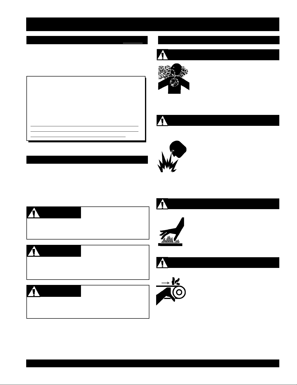
The three (3) Safety Messages shown below will inform you
about potential hazards that could injure you or others. The
Safety Messages specifically address the level of exposure to
the operator , and are preceded by one of three words: DANGER,
WARNING, or CAUTION.
Lethal Exhaust Gases
Engine exhaust gases contain poisonous
carbon monoxide. This gas is colorless and
odorless, and can cause death if inhaled.
NEVER operate this equipment in a confined
area or enclosed structure that does not
provide ample free flow air.
Explosive Fuel
Gasoline is extremely flammable, and its
vapors can cause an explosion if ignited. DO
NOT start the engine near spilled fuel or
combustible fluids. DO NOT fill the fuel tank
while the engine is running or hot. DO NOT
overfill tank, since spilled fuel could ignite if it
comes into contact with hot engine parts or
sparks from the ignition system. Store fuel in
approved containers, in well-ventilated areas
and away from sparks and flames. NEVER
use fuel as a cleaning agent.
DANGERDANGER
DANGER
DANGERDANGER
You WILL be
if you DO NOT follow these directions.
WARNINGWARNING
WARNING
WARNINGWARNING
You CAN be KILLED or
you DO NOT follow these directions.
CAUTICAUTI
CAUTION
CAUTICAUTI
You CAN be
these directions.
Potential hazards associated with PORTO-SCREED operation
will be referenced with
throughout this manual, and will be referenced in conjunction
with Safety
Message Alert Symbols
KILLED
INJURED
if you DO NOT f ollo w
Hazard Symbols
or
SERIOUSLY INJURED
SERIOUSLY INJURED
which appear
.
if
Burn Hazards
Engine components can generate extreme heat.
To prevent burns, DO NOT touch these areas
while the engine is running or immediately after
operations. NEVER operate the engine with
heat shields or heat guards removed.
Rotating Parts
NEVER operate equipment with covers, or
guards removed. Keep
and
clothing
prevent injury.
away from all moving parts to
fingers, hands, hair
STOW PORTO-SCREED — OPERATION & PARTS MANUAL — REV. #1 (03/17/04) — PAGE 7
Page 8

PORTO-SCREED PSH— SAFETY MESSAGE ALERT SYMBOLS
Respiratory Hazard
ALWAYS wear approved respiratory protection.
Sight and Hearing hazard
ALWAYS wear approved eye and hearing
protection.
Equipment Damage Messages
Other important messages are provided throughout this manual
to help prevent damage to your PSH, other property, or the
surrounding environment.
The "NOTE" symbol will be used
NOTE
whenever important or special
information should be referenced.
PAGE 8 — STOW PORTO-SCREED — OPERATION & PARTS MANUAL — REV. #1 (03/17/04)
Page 9

PORTO-SCREED PSH — RULES FOR SAFE OPERATION
RULES FOR SAFE OPERATION
CAUTION
Failure to follow instructions in this manual may lead to
serious injury or even death! This equipment is to be operated
by trained and qualified personnel only! This equipment is
for industrial use only.
The following safety guidelines should always be used when
operating the
SAFETY
■
ALWAYS read, understand, and follow
procedures in Operator’s Manual before
attempting to operate or service this
equipment. Make sure the operating
instructions are available and accessible
to the operator.
■
This equipment should not be operated by persons under the
minimum statutory age limit.
■
NEVER use this machine for any purpose other than those
described in this manual.
■
NEVER operate the PSH without proper protective clothing,
shatterproof glasses, steel-toed boots and other protective
devices required by the job.
PORTO-SCREED.
■
NEVER operate this equipment when not feeling well due to
fatigue, illness or taking medicine.
■
NEVER operate the PSH under the influence or drugs or
alcohol.
■
ALWAYS check the PSH for loosened nuts or bolts before
starting
■
NEVER touch the hot exhaust manifold, muffler
or cylinder. Allo w these parts to cool before
servicing the PSH.
■
High Temperatures – Allow the engine to
cool before adding fuel or performing service
and maintenance functions. Contact with
components can cause serious burns.
■
The engine of this PSH requires an adequate free flow of
cooling air. NEVER operate the PSH in any enclosed or narro w
area where free flow of
the air is restricted. If
the air flow is restricted
it will cause serious
damage to the engine
and may cause injury
to people. Remember
the engine gives off
DEADLY
monoxide gas.
hot!
carbon
■
■
■
Manufacturer does not assume responsibility for any accident
due to equipment modifications. Unauthorized equipment
modification will void all warranties. Any modification which
could lead to a change in the original characteristics of the
machine should be made only by the manufacturer who shall
confirm that the machine is in conformity with appropriate
safety regulations.
■
ALWAYS wear proper
protection equipment when operating the PSH.
respiratory
(mask),
hearing
and
eye
■
■
■
■
■
ALWAYS refuel in a well-ventilated
area, away from sparks and open
flames.
NEVER operate the PSH in an
explosive atmosphere or near
combustible materials. An explosion or
fire could result causing severe
bodily
harm or even death.
ALWAYS use extreme caution when w orking with flammable
liquids. When refueling, stop the engine and allow it to cool.
NEVER
Fire or explosion could result from
vapors
T opping-off to filler port is dangerous, as it tends to spill fuel.
ALWAYS close the fuel shut-off valve bef ore refueling.
NEVER use engine fuel as a cleaning agent.
smoke
, or if fuel is spilled on a
around or near the machine.
hot!
fuel
engine.
STOW PORTO-SCREED — OPERATION & PARTS MANUAL — REV. #1 (03/17/04) — PAGE 9
Page 10

PORTO-SCREED PSH — RULES FOR SAFE OPERATION
■
Whenever necessary, replace nameplate, operation and
Maintenance Safety
safety decals when they become difficult read.
■
■
NEVER Run engine without air filter. Severe engine damage
may occur. Service air filter frequently to prevent carburetor
malfunction.
■
AVOID wearing jewelry or loose fitting clothing that may snag
on the controls or moving parts as this can cause a serious
injury.
■
ALWAYS keep clear of
rotating
or
moving parts
while
operating the PSH.
■
Moving Parts – Shut down the engine before performing
service or maintenance functions. Contact with moving parts
■
■
■
■
■
can cause serious injury.
■
ALWAYS clear the work area around the screed of debr is
and obstructions to prevent tripping and/or falling onto the
screed.
■
NEVER leave the machine
unattended
while running, even
Emergencies
■
for a brief moment. DO NOT leave the screed until it comes
to a complete stop.
■
ALWAYS store equipment properly when it is not being used.
Equipment should be stored in a clean, dry location out of the
reach of children.
■
ALWAYS use factor y authorized par ts for replacement.
■
NEVER lubricate components or attempt service on a running
machine.
ALWAYS allow the machine a proper amount of time to cool
before servicing.
Keep the machinery in proper running condition.
Fix damage to the machine immediately and always replace
broken parts.
Dispose of hazardous waste properly . Examples of potentially
hazardous waste are used motor oil, fuel and fuel filters.
DO NOT use food or plastic containers to dispose of
hazardous waste.
ALWAYS know the location of the nearest
ALWAYS know the location of the nearest and
fire extinguisher
first aid kit
.
.
■
Refer to the
technical questions or information
HONDA Engine Owner's Manual
for engine
recommended by the
manufacturer for this equipment. Damage to the equipment
and/or injury to user may result.
■
No one other than the operator is to be in the working area
when the porto-screed is in operation.
■
Always observe all applicable compulsory regulations
■
relevant to en vironmental protection, especially , fuel storage,
the handling of hazardous substances, and the wearing of
protective clothing and equipment. Instruct the user as
necessary, or, as the user, request this information and
training.
Transporting
■
ALWAYS shutdown engine before transporting.
■
Tighten fuel tank cap securely and close fuel cock to prevent
fuel from spilling.
■
Drain fuel when transporting PSH over long distances or
bad roads.
■
When placing the PSH inside a truck-bed for transport,
always tie-down the PSH.
In emergencies
nearest phone or
always
know the location of the
keep a phone on the job site
.
Also know the phone numbers of the nearest
ambulance, doctor
and
fire department
. This
information will be invaluable in the case of an
emergency.
■
ALWAYS use proper lifting techniques when moving the PSH.
PAGE 10 — STOW PORTO-SCREED — OPERATION & PARTS MANUAL — REV. #1 (03/17/04)
Page 11

PORTO-SCREED PSH— OPERATION AND SAFETY DECALS
OPERATION AND SAFETY DECALS
The PORTO-SCREED walk-behind PSH is equipped with a number of operation and saf ety decals. These decals are provided for
operator safety and maintenance information. Should any of these decals become un readable, replacements can be ob tained from
your dealer.
WARNING
P/N 20109-001
To avoid injury,
you MUST read
and understand
operator’s manual
before using this
machine.
This machine to
be operated by
qualified
personnel only.
Ask for training
as needed.
P/N 35137
P/N35137
A
“BELT DRIVE”
B
“CHECK”
BELT DRIVE
GEAR DRIVE
CHECK
CLOCKWISE
GEAR DRIVE
CHECK
P/N 20525
P/N 36099 (ISO Blue)
WARNING!
KEEP GUARDS
IN PLACE
P/N 21302
P/N 21571
MODEL
SERIAL NO.
CONTACT
SERVICE
DEPARTMENT
D
W
E
R
O
P
C
O
D
E
A
T
P/N 13118
P/N 25263-001
C
“HOT”
D
“LUBRICATION”
HOT
LUBRICATION
LUBRICATION
COUNTER
CLOCKWISE
LIFTING POINTLIFTING POINT
LUBRICATION
LUBRICATION
DECAL SHEET
INTL STDS ISO
P/N 11246
Figure 2. PORTO-SCREED PSH Decals
STOW PORTO-SCREED — OPERATION & PARTS MANUAL — REV. #1 (03/17/04) — PAGE 11
Page 12

PORTO-SCREED PSH— INTRODUCTION
INTENDED USE
Operate the PSH P orto-Screed and components in accordance
with the manufacturer's instructions. Any use other than for stated
operation is considered contrary to designated use. The risk of
such use lies entirely with the user. The manufacturer cannot be
held liable for damages as a result of misuse.
INTRODUCTION
The STOW MODEL PSH PORTO-SCREED is designed for
vibration screeding concrete. Vibr ation screeding with the STOW
Porto-screed is the ideal way to strike-off and vibr ate concrete
sidewalks, floors, patios, and even bridge decks.
The PSH Porto-Screed incorporates a variety of features that
provide for ease of use. Among these are a throttle that allows
selection of the appropriate vibration required for proper
screeding, a free-swing handle, a handle-stop on the frame, a
centrifugal clutch, recoil engine starter and a remote throttle
control mounted on the handle within easy reach of the operator .
Figure 3. STOW Model PSH Porto-Screed
PAGE 12 — STOW PORTO-SCREED — OPERATION & PARTS MANUAL — REV. #1 (03/17/04)
Page 13

PORTO-SCREED PSH— ASSEMBLY
ASSEMBLY
CONTROLS AND COMPONENTS
WARNING
Whenever assembling, lubricating or adjusting any part of the
screed, make certain the engine is stopped with the spark plug
wire disconnected and secured away from contact with the spark
plug.
1. Handle Assembly – Gather all handle parts shown in the
illustration below . Place them in front of the machine (side
farthest from the engine). See Figure 4.
Figures 5 shows the location of the basic controls or components,
for the
of each control or component
Figure 5. Controls and Components
PORTO-SCREED PSH
. Listed below is a brief explanation
1. Throttle Control Lever – Controls the speed of the engine.
Move the hand lever towards the operator to increase
engine speed (high), away from the operator to decrease
engine speed (low).
2. Handle Bar – When operating the PSH, place both hands
on the bar to maneuver the PSH.
3. Engine – This PSH uses a Honda GX120 gasoline
Figure 4. Handle Assembly
2. Slip throttle cable "O-ring" (A) over the right handle rod (B).
3. Slide the handle bar (C) over the handle rods. Ensure the
side with the two holes are to the right.
4. Fasten the handle bar to the left handle rod (D) using bolt
and nut (E and F). F asten handle bar (with throttle control
lever) to the right handle rod. Fasten the throttle control
lever (G) to the handle bar with pan head screws (H).
5. Insert the flanged spacer (I) into the holes located in the
flattened portions of the handle rods making sure the
flanged end of both spacers are toward the outside.
6. Insert bolts (J) through the handle rods and the main frame
(K). Install the lockwasher and nut (L and M) to both bolts.
engine. See following sections on engine components
and engine operation.
4. Frame – Supports engine and handle assemblies; allows
clamping to screeding beams.
NEVER attempt to
assistance of another person to help lift the PSH .
Moving the PSH
CAUTION
lift
the PSH by yourself . ALWAYS get the
7. Connect throttle wire (N) to the engine. Follow instructions
in the engine manual for proper attachment.
STOW PORTO-SCREED — OPERATION & PARTS MANUAL — REV. #1 (03/17/04) — PAGE 13
This PSH is light weight, however for safety purposes always
two people
use
to lift the PSH up onto a slab of concrete.
Page 14

PORTO-SCREED PSH— BASIC ENGINE
INITIAL SERVICING
The engine (Figure 6) must be checked for proper lubrication and
filled with fuel prior to operation. Refer to the manufacturer's engine
manual for instructions & details of operation and servicing. The
engine shown above is a HONDA engine, operation for other
types of engines may vary somewhat.
1. Fuel Filler Cap – Remove this cap to add unleaded
gasoline to the fuel tank. Make sure cap is tightened
securely. DO NOT ov er fill.
Figure 6. Engine Controls and Components
6. Choke Lever – Used in the starting of a cold engine, or in
cold weather conditions. The choke enriches the fuel
mixture.
7. Air Cleaner – Prevents dirt and other debris from entering
the fuel system. Remove wing-nut on top of air filter
cannister to gain access to filter element.
NOTE
DANGER
Adding fuel to the tank should be done only
when the engine is stopped and has had an
opportunity to cool down. In the event of a fuel
spill, DO NOT attempt to start the engine until
the fuel residue has been completely wiped up,
and the area surrounding the engine is dry .
2. Throttle Lever – Used to adjust engine RPM speed (lever
SLOW
advanced forward
FAST
).
, lever back toward operator
8. Spark Plug – Provides spark to the ignition system. Clean
spark plug once a week.
9. Muffler – Used to reduce noise and emissions.
Operating the engine without an air
filter, with a damaged air filter, or a
filter in need of replacement will
allow dirt to enter the engine, causing
rapid engine wear .
WARNING
Engine components can generate extreme heat.
To prevent burns, DO NOT touch these areas
while the engine is running or immediately after
operating. NEVER operate the engine with the
muffler removed.
3. Engine ON/OFF Switch –
OFF
starting,
4. Recoil Starter (pull rope) – Manual-starting method. Pull
the starter grip until resistance is felt, then pull briskly and
smoothly.
5. Fuel Valve Lever – OPEN to let fuel flo w, CLOSE to stop
the flow of fuel.
position stops engine operation.
PAGE 14 — STOW PORTO-SCREED — OPERATION & PARTS MANUAL — REV. #1 (03/17/04)
ON
position permits engine
10. Fuel Tank – Holds unleaded gasoline. For additional
11. Oil Drain Plug – Remove this plug to remove oil from the
12. Dipstick/Oil Filler Cap – Remove this cap to determine if
information refer to engine owner's manual.
engine's crankcase.
the engine oil is low. Add oil through this filler port as
recommended in Table 3.
Page 15

PRE-INSPECTION
CAUTION
NEVER operate the PSH in a confined area
or enclosed area structure that does not
provide ample
ALWAYS wear approved eye and hearing
protection before operating the PSH.
free flow of air
.
PORTO-SCREED PSH— PRE-INSPECTION
Reference manufacturer engine
NOTE
manual for specific servicing
instructions.
Before Starting
1. Read safety instructions at the beginning of manual.
2. Clean the PSH, removing dirt and dust, particularly the
engine cooling air inlet, carburetor and air cleaner .
3. Check the air filter for dirt and dust. If air filter is dirty , replace
air filter with a new one as required.
4. Check carburetor for external dirt and dust. Clean with dry
compressed air.
5. Check fastening nuts and bolts for tightness.
Engine Oil Check
1. To check the engine oil level, place the PSH on secure
level ground with the engine stopped.
2. Remove the filler dipstick from the engine oil filler hole
(Figure 7) and wipe clean.
Fuel Check
Motor fuels are highly flammable and can
be dangerous if mishandled. DO NOT
smoke while refueling. DO NOT attempt to
refuel the PSH if the engine is
running
Figure 8. Engine Oil Dipstick (Oil Level)
epyTliO.3elbaT
nosaeS erutarepmeT epyTliO
remmuS rehgiHroC°52 03-W01EAS
llaF/gnirpS C°01~C°52 02/03-W01EAS
retniW rewoLroC°0 01-W01EAS
DANGER
hot!
or
.
1. Remove the gasoline cap located on top of fuel tank.
2. Visually inspect to see if fuel level is low. If fuel is low, replenish
with unleaded fuel.
Figure 7. Engine Oil Dipstick (Removal)
3. Insert and remove the dipstick without screwing it into the filler
neck. Check the oil level shown on the dipstick.
4. If the oil level is low (Figure 8), fill to the edge of the oil filler
hole with the recommended oil type (T able 3). Maximum oil
capacity is .56 liters (0.59 quarts).
STOW PORTO-SCREED — OPERATION & PARTS MANUAL — REV. #1 (03/17/04) — PAGE 15
3. When refueling, be sure to use a strainer for filtration. DO
NOT top-off fuel. Wipe up any spilled fuel.
V-Belt Check
A worn or damaged V -belt can adv ersely affect the performance
of the PSH. If a V -belt is def ective or worn simply replace the V belt as outlined in the maintenance section of this manual.
Page 16

PORTO-SCREED PSH — INITIAL START-UP
INITIAL START-UP
Lifting and Moving the PSH
Even though the PSH is lightweight, always use two people when
lifting or moving the PSH.
This section is intended to assist the operator with the initial
start-up of the PSH. It is extremely important that this section be
read carefully before attempting to use the PSH in the field.
DO NOT attempt to operate the PSH until the
Safety, General Information and Inspection
sections of this manual have been read and
thoroughly understood.
Starting the Engine
4. Place the
starting a
Figure 11. Engine Choke Lever
choke lever
warm engine
(Figure 12) in the "
or the
temperature is warm.
OPEN
" position if
1. Place the engine
position.
Figure 9. Engine Fuel Valve Lever
2. Place the trowel's
position.
fuel valve lever
throttle lever
(Figure 9) to the "ON"
(Figure 10) to the "IDLE"
Figure 12. Engine Choke Lever (Open)
5. Place the
position.
engine ON/OFF switch
(Figure 13) in the "
ON
"
Figure 10. Throttle Lever (Idle Position)
3. Place the
if starting a
choke lever
Figure 13. Engine ON/OFF Switch
(Figure 11) in the "
cold
engine.
PAGE 16 — STOW PORTO-SCREED — OPERATION & PARTS MANUAL — REV. #1 (03/17/04)
CLOSED
" position
Page 17

PORTO-SCREED PSH — INITIAL START-UP
6. Grasp the starter grip (Figure 14) and slowly pull it out. The
resistance becomes the hardest at a certain position, corresponding to the compression point. Pull the starter grip briskly
and smoothly for starting.
Figure 14. Starter Grip
7. If the engine has started, slowly return the choke lever
OPEN
(Figure 12) to the
repeat steps 1 through 6.
position. If the engine has not started
Stopping The Engine
1. Move the throttle lever to the IDLE or SLOW position (Figure
15) and run the engine for three minutes at low speed.
2. After the engine
“OFF” position (Figure 16).
Figure 16. Engine ON/OFF Switch (OFF Position)
3. Close the
valve lever to the OFF position.
cools
, turn the engine start/stop switch to the
fuel shut- off valve
(Figure 17) by moving the fuel
8. Before the PSH is placed into operation, run the engine for
several minutes. Check for fuel leaks, and noises that would
associate with a loose V -belt cov er or component.
Figure 15. Throttle Lever (Run Position)
Figure 17. Fuel Valve Lever (OFF Position)
STOW PORTO-SCREED — OPERATION & PARTS MANUAL — REV. #1 (03/17/04) — PAGE 17
Page 18

PORTO-SCREED PSH — OPERATION
OPERATION
4. Start the engine as previously described. Refer to the
1. Place the machine on the screeding beams (Items B,
Figure 18) and install the clamping studs (Items A).
CAUTION
Do not over tighten the clamping studs. Check the clamping
studs periodically during operation and retighten them if
they loosen.
For beam lengths up to 14 ft. (4.2
meters) "2x4" wooden or
NOTE
lightweight beams are
recommended. For longer lengths,
up to 20 ft. (6 meters), "2x6" beams
should be used.
5. To begin operation move the throttle le ver (Item C , Figure
Engine Manual Starting Instructions for complete starting
instructions of the engine. Allow the engine to warm up 1-2
minutes before oper ating. The throttle le ver should be set
to permit the engine to warm up WITHOUT engaging the
centrifugal clutch and causing the machine to vibrate and
move f orward under its own pow er.
18) to the high speed or “Full Throttle” position quickly to
prevent damage from occurring to the clutch. The “Full
Throttle” position of this machine has been pre-set at the
factory.
DO NOT alter .this setting since
NOTE
damage to the eccentric bearings
can result and both the engine
and machine warranty will be
automatically VOIDED .
C
B
TRAVEL
A
Figure 18. Screeding Beams
2. P osition the screed on the forms with the eccentric facing
the desired direction of travel.
3. P our the concrete into the f orms to a height just above the
bottom edge of the sceeding beams and at least 10 ft.
ahead of the unit.
Stopping The Engine
1. Move the throttle le ver to the IDLE or SLOW position (Item
C, Figure 15) and run the engine for three minutes at low
speed.
cools
2. After the engine
, turn the engine start/stop switch to the
“OFF” position (Figure 16).
PAGE 18 — STOW PORTO-SCREED — OPERATION & PARTS MANUAL — REV. #1 (03/17/04)
Page 19

PORTO-SCREED PSH — MAINTENANCE
MAINTENANCE
See the engine manual supplied with your
machine for appropriate engine maintenance
schedule and troubleshooting guide for
problems.
CAUTION
ALWAYS allow the engine to cool before
servicing. NEVER attempt any maintenance
hot!
work on a
WARNING
Whenever assembling, lubricating, cleaning or adjusting any
part of the screed, make certain the engine is stopped with the
spark plug wire disconnected and secured away from contact
with the spark plug.
engine.
B
Figure 19. V-Belt Tensioning
A
C
E
D
Lubrication
A. Engine: Lubricate the engine-refer to the “Engine Manual”.
Always check the engine for proper level of engine oil. The
engine warranty is VOID if run without oil. Check the oil level
daily and change the oil weekly .
B. Clutch: A few drops of lightweight oil occasionally squirted
between the clutch mechanism cover and the floating cone will
help keep the mechanism free of debris and is the only clutch
maintenance required
C. Pillow Block Bearings: After every 40 hours of
operation, remove the belt guard (Item B, Figure 18) and
grease each bearing (Item D) with quality grade multipurpose grease.
V-Belt Tensioning
T o tension the V -Belt (Item A, Figure 19)perform the follo wing:
1. Remove the belt guard (Item B).
2. Loosen the four (4) bolts (Item C) and slide the pillow
block (Item D) away from or toward the engine to tighten or
loosen the V -Belt until proper tension is achieved.
Cleaning
Clean the machine following each screeding operation before
concrete is allowed to dry on the machine. This is especially
important on the clamping stud threads. Keeping the belt
guard in place during operation not only provides a measure
of safety , b ut also helps to protect the eccentric, centrifugal
clutch, and belt from foreign matter .
General
Check for broken or missing componenst before each use.
Check all bolts for tightness bef ore each use. Tighten if
necessary .
MAINTENANCE SCHEDULE
Daily (8-10 Hours)
1. Check the oil level in the engine crankcase; fill as necessary.
2. Check V-belt.
Weekly (50-60 Hours)
1. Check the engine air filter and replace as necessary .
NOTE: Before retightening the pillow block bolts, be sure to
align the eccentric assembly (Item E) perpendicular to the belt.
STOW PORTO-SCREED — OPERATION & PARTS MANUAL — REV. #1 (03/17/04) — PAGE 19
2. Replace engine oil and filter as necessary, see engine
manual.
Page 20

PORTO-SCREED PSH — TROUBLESHOOTING (ENGINE)
)ENIGNE(GNITOOHSELBUORT.4ELBAT
MOTPMYSESUACELBISSOPNOITULOS
?gnigdirbgulpkrapS
ontub,elbaliavasileuf",tratsottluciffiD
."gulpkrapstaKRAPS
?noitalusni
?evitcefedliocnoitingI.liocnoitingiecalpeR
dna,elbaliavasileuf",tratsottluciffiD
."gulpkrapsehttatneserpsiKRAPS
?gnitiucric
?epytleufgnorW
?gulpkrapsnotisopednobraC .gulpkrapsecalperronaelC
gulpkrapstneicifedoteudtiucrictrohS
?paggulpkrapsreporpmI.pagreporpotteS
?detrohssihctiwsFFO/NO
?ytridstniop,pagkrapsreporpmI
trohsronrownoitalusniresnednoC
?gnitiucrictrohsronekorberiwgulpkrapS
.nrowfiecalper
.hctiws
.stniopnaelc
.gniriw
ronoitalusni,pagkcehC
.gulpkrapsecalper
,noitalusnigulpkrapskcehC
ecalper,gniriwhctiwskcehC
dnapagkrapstcerrocteS
.resnednocecalpeR
gulpkrapsevitcefedecalpeR
ecalperdna,metsysleufhsulF
.leuffoepyttcerrochtiw
?metsysleufnitsudroretaW.metsysleufhsulF
kraps,elbaliavasileuf",tratsottluciffiD
."lamronsinoisserpmocdnatneserpsi
kraps,elbaliavasileuf",tratsottluciffiD
."wolsinoisserpmocdnatneserpsi
.blubgnimirpedisnitneserpleufoN
?ytridrenaelcriA.renaelcriaecalpeR
)dlocenignE(?nepOekohC.ekohCesolC
)mrawenignE(?desolCekohC.ekohCnepO
?nrowrednilycro/dnagnirnotsiP
tongulpkrapsro/dnadaehrednilyC
?ylreporpdenethgit
?degamad
?knatleufnielbaliavatonleuF .leuffoepyttcerrochtiwlliF
?deggolcretlifleuF.retlifleufecalpeR
?enilleufniriA.enilleufdeelB
?dedurtorprokcutsevlavtsuahxe/noitcuS.sevlavtaes-eR
teksaggulpkrapsro/dnateksagdaeH
?deggolcelohrehtaerbpacknatleuF .packnatleufecalperronaelC
rodnasgnirnotsipecalpeR
.notsip
dnastlobdaehrednilyceuqroT
.gulpkraps
gulpkrapsdnadaehecalpeR
.steksag
PAGE 20 — STOW PORTO-SCREED — OPERATION & PARTS MANUAL — REV. #1 (03/17/04)
Page 21

PORTO-SCREED PSH — SUGGESTED SPARE PARTS
SUGGESTED SPARE PARTS
PORTO-SCREED PSH
1 TO 3 UNITS WITH HONDA GX120K1QX2 ENGINE
1 to 3 Units
Qty. ..... P/N ........................ Description
1 ...........30033-401............ CABLE, THROTTLE ASM
4 ...........22094-006............ O-RING (FASTENER)
4 ........... 1162 A .................. CAP, GREASE ZERK
3 ...........07055-028............ V-BELT 4L280
3 ...........19977 ................... KNOB, CLAMP
1 ...........17620ZH7023...... TANK CAP (HONDA)
2 ...........17210ZE1505 ...... AIR CLEANER ELEMENT
3 ...........9807956846......... SPARK PLUG
1 ...........28462ZH8003...... ROPE, RECOIL STARTER
NOTE
The contents of this parts catalog
are subject to change without
.
notice
STOW PORTO-SCREED — OPERATION & PARTS MANUAL — REV. #1 (03/17/04) — PAGE 21
Page 22

NAMEPLATE AND DECALS
PORTO-SCREED PSH — NAMEPLATE AND DECALS
A
BELT DRIVE
CLOCKWISE
P/N 36099 (ISO Blue)
1
WARNING!
KEEP GUARDS
IN PLACE
P/N 21302
A
“BELT DRIVE”
GEAR DRIVE
3
B
CHECK
GEAR DRIVE
CHECK
4
C
HOT
DECAL SHEET
INTL STDS ISO
P/N 11246
2
D
LUBRICATION
P/N 20525 SM
B
“CHECK”
1-1/2 x 2-1/4
C
“HOT”
8
MODEL
SERIAL NO.
LUBRICATION
CONTACT
SERVICE
9
!
G
IN
N
R
A
W
S
D
R
A
U
G
P
E
E
C
E
A
K
L
P
N
I
E
D
R
W
O
P
D
C
E
O
T
A
DEPARTMENT
COUNTER
CLOCKWISE
LIFTING POINTLIFTING POINT
LUBRICATION
LUBRICATION
P/N 35137
P/N 11092
10
D
7
W
E
R
O
P
C
O
D
E
A
T
P/N 13118
6
D
LUBRICATION
P/N 20109-001
“LUBRICATION”
P/N 25263-001
PAGE 22 — STOW PORTO-SCREED — OPERATION & PARTS MANUAL — REV. #1 (03/17/04)
5
Page 23

PORTO-SCREED PSH — NAMEPLATE AND DECALS
NAMEPLATE AND DECALS
NO. PART NO. PART NAME QTY. REMARKS
1 21302 DECAL: GU ARD WARNING .................................. 1 ....... SAFETY ITEM
2 20525 SMALL DECAL: WARNING, CA PROP 65......................... 1 ....... SAFETY ITEM
3 36099 DECAL: HELMET, SHOE AND GLOVE ................ 1 ....... SAFETY ITEM
4 11246 DECAL: SHEET-INTERNA TIONAL STAND ARDS.. 1 ....... SAFETY ITEM
5 20109-001 DECAL: STOW PORTO-SCREED 1
6 25263-001 DECAL: CAUTION GAS VIB ................................. 1 ....... SAFETY ITEM
7 13118 DECAL: POWDER COATED 1
8 NAME PLATE ........................................................ 1 ....... CONTACT PARTS DEPARTMENT
9 35137 DECAL: W ARNING, READ MANUAL .................... 1 ....... SAFETY ITEM
10 11092 DECAL: CE 1
SEE DECAL ILLUSTRATIONS ON PAGE 11
NOTE
The contents of this parts
catalog are subject to
change without notice.
STOW PORTO-SCREED — OPERATION & PARTS MANUAL — REV. #1 (03/17/04) — PAGE 23
Page 24

ASSEMBLY
PORTO-SCREED PSH — ASSEMBLY
30
33
19
34
20
22
21
32
36
1
2
7
37
3
31
26
5
6
4
5
6
8
9
16
17
29
14
10
13
12
11
35
18
8
19
20
15
24
7
23
15
25
5
27
PAGE 24 — STOW PORTO-SCREED — OPERATION & PARTS MANUAL — REV. #1 (03/17/04)
28
19
Page 25

PORTO-SCREED PSH — ASSEMBLY
ASSEMBLY
NO. PART NO. PART NAME QTY. REMARKS
1 21387 ENGINE, 4 HP. HONDA GX120K1QX2 1
2 12704-304 CLUTCH 1
3 18241-301 BEL T GUARD...................................................... 1 ......... SAFETY ITEM
4 0655 SCREW, HHC 5/16 - 18 X 3/4" 3
5 0161 C LOCK W ASHER 5/16” 9
6 0300 B FLAT W ASHER 5/16” 7
7 0949 HEX NUT 1/4- 20 8
8 0181 B LOCK W ASHER 1/4” 8
9 15488-001 PLATE, ENGINE MOUNT 1
10 5283 NUT, NYLOC 5/16 - 18 4
11 08297-008 NUT, LOCK 1/2 - 20 GRIPCO 1
12 0477 FLATWASHER, 1/2 1
13 36493 PULLEY, AS20 X 5/8 1
13A 07051-017 PULLEY, 1/8" KEYWAY ...................................... 1 .........SERVICE ONLY
14 07055-028 V-BELT4L280 1
15 27023-001 BEARING, P-BLOCK 2
16 1162 A CAP, GREASE ZERK #2 2
17 4001 FLAT WASHER 3/8” 4
18 1284 SCREW, HHCS 3/8- 16 X 1” 1
19 36494 KEY WOODRUFF #6 1
20 21101-002 SPINDLE, ECCENTRIC 1
21 0202 SCREW, HHC 5/16 - 18 X 3/4" 2
22 13658-001 SP ACER, HANDLE 2
23 4014 SCREW, 2 - 3/16 P-K TYPE U-DRIVE 2
24 11679-001 MOUNT , ISOLATION 4
25 0161 D NUT , HEX 5/16 X 18 2
26 0105 SCREW , HHC 5/16- 18 X 1-1/2” 4
27 12706-401 FRAME 1
28 19977 KNOB, CLAMP 6
29 11831-001 SP ACER, ECCENTRIC PULLEY 1
30 36491 TUBE, HANDLE LEG 2
31 36492 TUBE, HANDLE 1
32 12714-006 SCREW, PHSHT METAL 10 X 3/8 SLOTTED 2
33 30033-401 CABLE, THROTTLE ASM 1
34 22094-006 O-RING 2
35 36499 PLATE, LOWER BELT GUARD........................... 1 .........SAFETY ITEM
36 1834 DEFLECTOR, EXHA UST .................................... 1 ......... SAFETY ITEM
37 1273 SCREW, HHST 8-32 X 3/8 2
STOW PORTO-SCREED — OPERATION & PARTS MANUAL — REV. #1 (03/17/04) — PAGE 25
Page 26

Effective: July 15, 2003
TERMS AND CONDITIONS OF SALE — PARTS
Effective: July 1, 2000
PAYMENT TERMS
Terms of payment for unit sales are 2% 15
days net 30 days from date of invoice unless
otherwise specifically stated on our invoice.
Parts invoices have terms of net 10 days.
Minimum parts billing is $15.00 net.
Applicable discounts will be computed on
merchandise value only. Late charges will be
assessed at prevailing rates. Cash discounts
cannot be taken on current billings if any
previously billed amounts are past due.
FREIGHT POLICY
Freight policy is established to offer customers
every advantage possible. Due to bulk freight
ratings on some equipment and other shipping
considerations, freight policies differ by
equipment type. Actual back freight may be
charged for shipments originating from other
than specified FOB warehouses. See Freight
Policy for details.
All STOW domestic sales are FOB nearest
available designated MQ/STOW warehouse.
Export orders are ex-works factory located in
Carson, CA or Boise, ID .
Additions to orders already shipped cannot be
accepted for freight minimums.
Should STOW elect to make partial shipments
of an order originally complying with the “freight
allowed” requirements, transportation charges
will be absorbed by STOW on any subsequent
shipment applying to that order.
All other orders will be shipped collect or prepaid
with charges added to the invoice. STOW’s
responsibility ceases when a signed manifest
has been obtained from the carrier, and any
claim for shortage or damage must be settled
between the consignee and the carrier.
Parts: FOB Carson, California or Boise,
Idaho. See Freight Policy for details and
additional discounts.
DROP SHIPMENTS
STOW reserves the right to refuse Drop
Shipments outside the normal service area of
the purchasing dealer.
FIELD WAREHOUSES
Field Warehouses are currently located in
California, Georgia, Idaho, Iowa, and New
Jersey
SPECIAL EXPEDITING SERVICE
The higher of a $35.00 surcharge or actual
costs will be added to the invoice for special
handling, including bus shipments, or in cases
where STOW personnel must personally deliver
the equipment or parts to the carrier.
RETURNED GOODS POLICY
1. A Returned Material Authorization (RMA)
must be approved by STOW prior to
shipment. Approvals for returned goods
must be with just cause and are at the
sole discretion of STOW. A copy of the
Authorization must accompany the shipment to the designated Warehouse.
2. Parts being returned must be listed as
currently supplied on the current parts list.
3. Parts must be in new and resalable
condition in the original package, with part
numbers clearly marked.
4. Units and accessories must be current
models in the latest price list and in new
and resalable condition.
5. Special order items are not returnable for
credit.
6. Credit on returned parts and units will be
issued at actual dealer net price at time of
purchase less 15% restocking charge.
7. All returned shipments are to be made to
the STOW designated receiving point,
freight prepaid at the sender’s e xpense.
Terms and Conditions of Sale
TERMS AND CONDITIONS OF
STOW Construction Equipment
SALE — PARTS
The sender will be notified of any material
received that does not meet the above
provisions. Such material will be held for 30
days from notification pending instructions. If a
reply is not received within 30 days, the material
will be returned to the sender at his expense
with no credit issued.
PRICING, REBATES AND
SPECIFICATIONS
Every effort will be made to provide adequate
notice of changes; however, prices and
equipment specifications are subject to change
without notice.
Price changes are effective on a specific date
and all orders received on or after that date will
be billed at the revised price.
Rebates for price reductions and added charges
for price increases will not be made for stock in
dealer inventory at the time of a price change.
STOW reserves the right to quote and sell direct
to Government agencies and to Original
Equipment Manufacturer accounts who use our
products as integral parts of their own products.
LIMITATION OF SELLER’S LIABILITY
STOW shall not be liable hereunder for damages
in excess of the purchase price of the item with
respect to which damages are claimed and in
no event shall STOW be liable for loss of profit
or good will or for any other special,
consequential or incidental damages.
LIMITATION OF WARRANTIES
There are no warranties, express or implied,
made by STOW. hereunder on Products
manufactured or distributed by it except the
warranty against defects in material and
workmanship on new Products to the original
purchaser, as set forth in the STOW New
Product Limited W arranty.
STOW CONSTRUCTION EQUIPMENT
A DIVISION OF MULTIQUIP
HANOVER MILL
FITZROY STREET
ASHTON-UNDER-LYNE
LANCASHIRE, OL7 OTL
UNITED KINGDOM
Atlanta • Boise • Newark • Quebec, Canada
Manchester, UK • Rio de Janeiro, BR • Puebla, MX
PH. 0161-339-2223
FAX. 0161-339-3226
E-MAIL: stow@stowmfg.com
www.stowmfg.com
PAGE 26 — STOW PORTO-SCREED — OPERATION & PARTS MANUAL — REV. #1 (03/17/04)
Page 27

NOTE PAGE
STOW PORTO-SCREED — OPERATION & PARTS MANUAL — REV. #1 (03/17/04) — PAGE 27
Page 28

OPERATION AND PARTS MANUAL
FOR HELP AND TECHNICAL ASSISTFOR HELP AND TECHNICAL ASSIST
FOR HELP AND TECHNICAL ASSIST
FOR HELP AND TECHNICAL ASSISTFOR HELP AND TECHNICAL ASSIST
(UNITED KINGDOM AND EUROPE)
PLEASE HAVE THE MODEL AND SERIAL NUMBER
ON-HAND WHEN CALLING
PP
ARAR
P
PP
LANCASHIRE, OL7 OLLANCASHIRE, OL7 OL
LANCASHIRE, OL7 OL
LANCASHIRE, OL7 OLLANCASHIRE, OL7 OL
UNITED KINGDOM (UK) CALL:UNITED KINGDOM (UK) CALL:
UNITED KINGDOM (UK) CALL:
UNITED KINGDOM (UK) CALL:UNITED KINGDOM (UK) CALL:
TS/SERTS/SER
AR
TS/SER
ARAR
TS/SERTS/SER
VICE/ WVICE/ W
VICE/ W
VICE/ WVICE/ W
ARRANTYARRANTY
ARRANTY
ARRANTYARRANTY
TT
T
TT
PHONE: 161-339-2223
FAX: 161-339-3226
ANCEANCE
ANCE
ANCEANCE
Atlanta • Boise • Newark • Quebec, Canada
Manchester, UK • Rio de Janeiro, BR • Puebla, MX
STOW CONSTRUCTION EQUIPMENT
A DIVISION OF MULTIQUIP
HANOVER MILL
FITZROY STREET
ASHTON-UNDER-LYNE
LANCASHIRE, OL7 OTL
UNITED KINGDOM
PH. 0161-339-2223
FAX. 0161-339-3226
E-MAIL: stow@stowmfg.com
www.stowmfg.com
 Loading...