

Page 1

OPERATION MANUAL
STAY-LEVEL HANDLEBAR SERIES
MODELS
PS706016
PS706020
PS706026
PS706030
PS706036
PAVEMENT SAW
(DEUTZ BF3L2011 DIESEL ENGINE)
Revision #2 (06/02/08)
To find the latest revision of this
publication, visit our website at:
www.multiquip.com
THIS MANUAL MUST ACCOMPANY THE EQUIPMENT AT ALL TIMES.
P/N 37434
Page 2
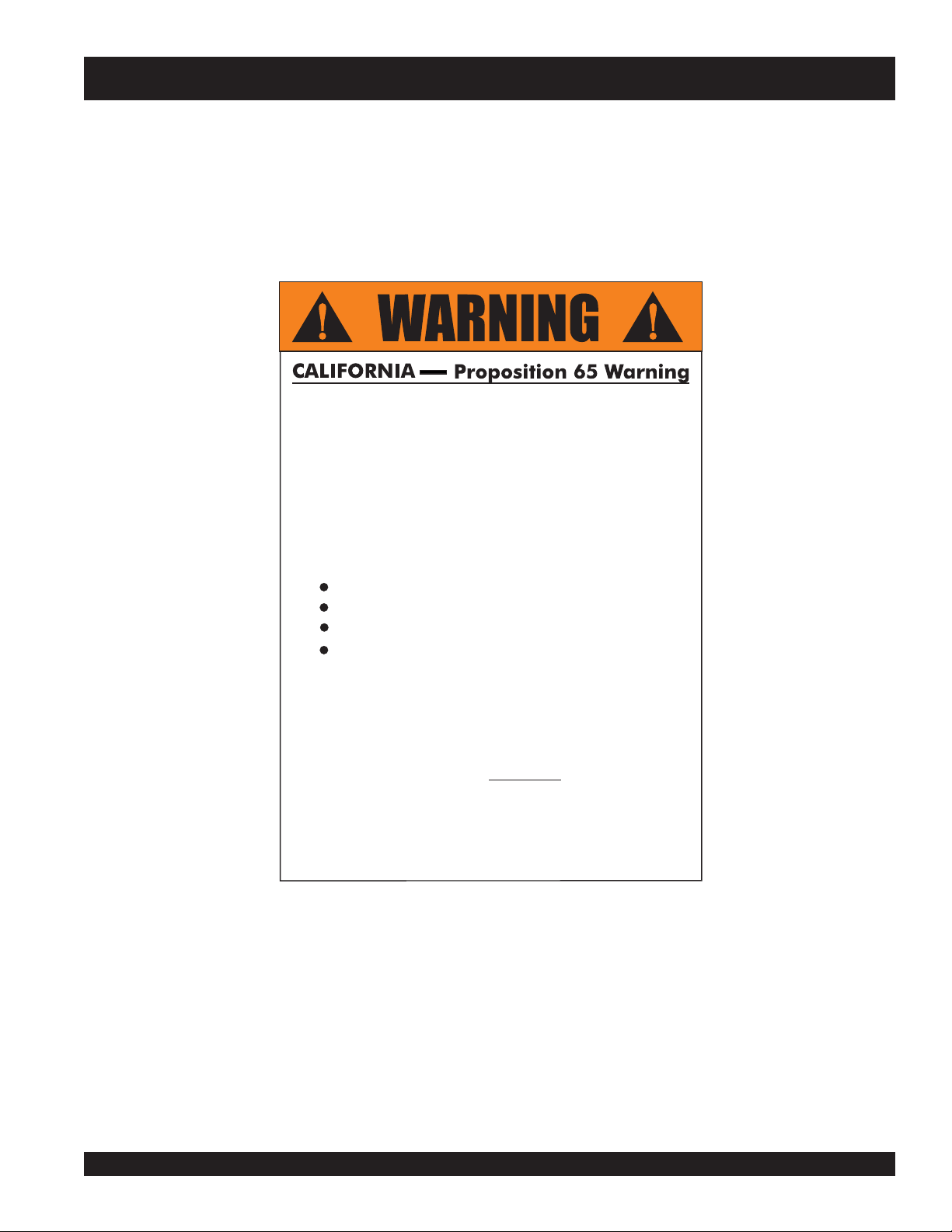
PROPOSITION 65 WARNING
Engine exhaust and some of
its constituents, and some dust created
by power sanding, sawing, grinding,
drillingandotherconstructionactivities
contains chemicals known to the State
of California to cause cancer, birth
defects and other reproductive harm.
Some examples of these chemicals are:
Leadfromlead-basedpaints.
Crystallinesilicafrombricks.
Cementandothermasonryproducts.
Arsenicandchromiumfrom chemically
treatedlumber.
Your risk from these exposures varies,
dependingonhowoftenyoudothistype
of work. To reduce your exposure to
these chemicals: work in aALWAYS
well ventilated area, and work with
approved safety equipment, such as
dust masks that are specially designed
to filter out microscopic particles.
Page 3
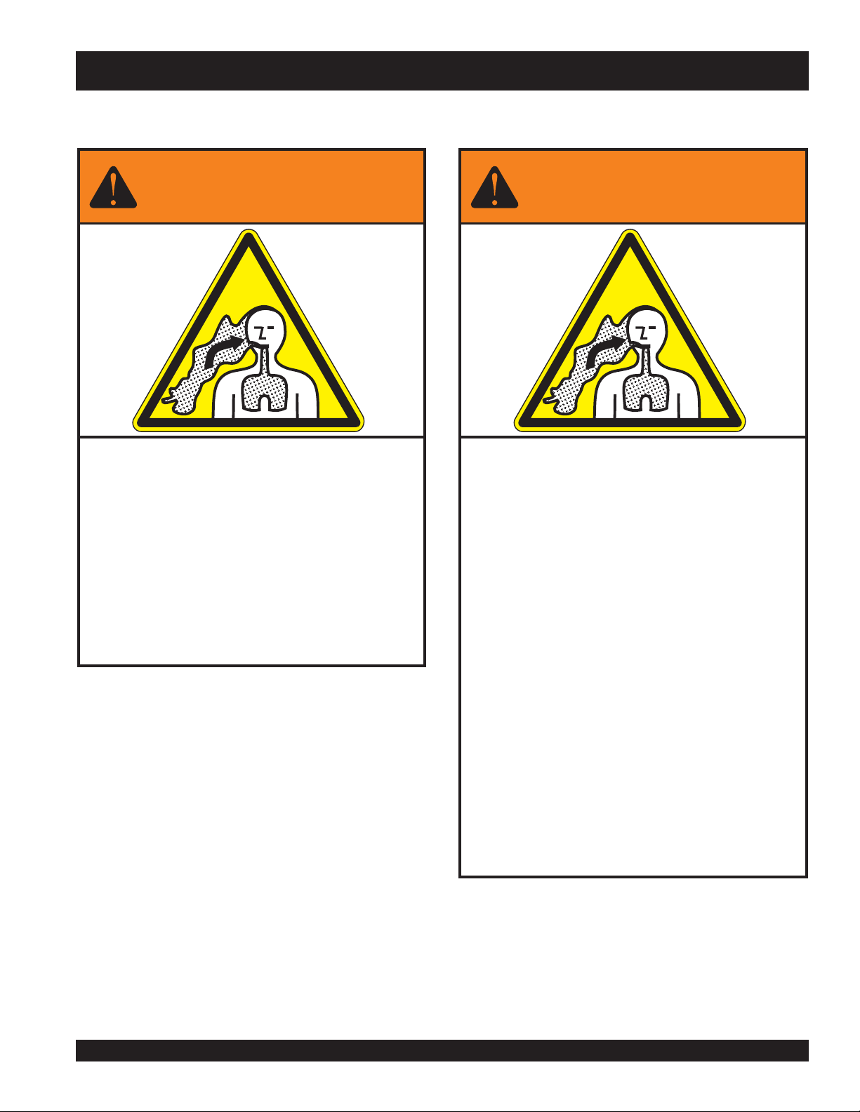
SILICOSIS/RESPIRATORY WARNINGS
WARNING
SILICOSIS WARNING RESPIRATORY HAZARDS
Grinding/cutting/drilling of masonry, concrete, metal and
other materials with silica in their composition may give
off dust or mists containing crystalline silica. Silica is a
basic component of sand, quartz, brick clay, granite and
numerous other minerals and rocks. Repeated and/or
substantial inhalation of airborne crystalline silica can
cause serious or fatal respiratory diseases, including
silicosis. In addition, California and some other
authorities have listed respirable crystalline silica as a
substance known to cause cancer. When cutting such
materials, always follow the respiratory precautions
mentioned above.
WARNING
Grinding/cutting/drilling of masonry, concrete, metal and
other materials can generate dust, mists and fumes
containing chemicals known to cause serious or fatal
injury or illness, such as respiratory disease, cancer,
birth defects or other reproductive harm. If you are
unfamiliar with the risks associated with the particular
process and/or material being cut or the composition of
the tool being used, review the material safety data
sheet and/or consult your employer, the material
manufacturer/supplier, governmental agencies such as
OSHA and NIOSH and other sources on hazardous
materials. California and some other authorities, for
instance, have published lists of substances known to
cause cancer, reproductive toxicity, or other harmful
effects.
Control dust, mist and fumes at the source where
possible. In this regard use good work practices and
follow the recommendations of the manufacturers or
suppliers, OSHA/NIOSH, and occupational and trade
associations. Water should be used for dust
suppression when wet cutting is feasible. When the
hazards from inhalation of dust, mists and fumes cannot
be eliminated, the operator and any bystanders should
always wear a respirator approved by NIOSH/MSHA for
the materials being used.
Page 4

PS7060 MULTIQUIP SAW — TABLE OF CONTENTS
Proposition 65 Warning ........................................... 2
Silicosis/Respiratory Warnings ................................ 3
Table of Contents .................................................... 4
Dimensions ............................................................. 5
Specifications .......................................................... 6
Engine Specifications .............................................. 7
Training Checklist .................................................... 8
Daily Pre-Operation Checklist ................................. 9
Safety Message Alert Symbols ........................ 10-11
Rules For Safe Operation ................................ 12-16
Intended Use/Familiarization ................................ 17
Serial Tag Information ........................................... 19
PS7060 — MULTIQUIP SAW
Controls and Indicators ......................................... 20
Components.......................................................... 21
Basic Engine Information ...................................... 22
Choosing Proper Blade Size ............................ 23-24
Specific Tools/Saw Blades ..................................... 25
Installing the Blade ........................................... 26-27
Blade Guards ................................................... 28-29
Water Delivery System .......................................... 30
SLH and Battery .................................................... 31
Fueling the Saw .................................................... 32
Pointer Adjustment ................................................ 33
Raise/Lower Controls............................................ 34
Blade Shaft Engage/Dis-engage........................... 35
Operation ......................................................... 36-37
Loading/Transporting ............................................ 38
Maintenance .................................................... 39-55
Troubleshooting ............................................... 56-58
Electrical Diagram To SN AF3700155 ................... 60
Electrical Diagram SN AF3700156 & Up .............. 61
Hydraulic Schematic To SN AF3700155 ............... 62
Hydraulic Schematic SN AF3700156 & Up ........... 63
Terms and Condition of Sale................................. 64
PAGE 4 — PS7060 MULTIQUIP SAW • OPERATION MANUAL — REV. #2 (06/02/08)
Specifications are subject to change without
notice.
Page 5
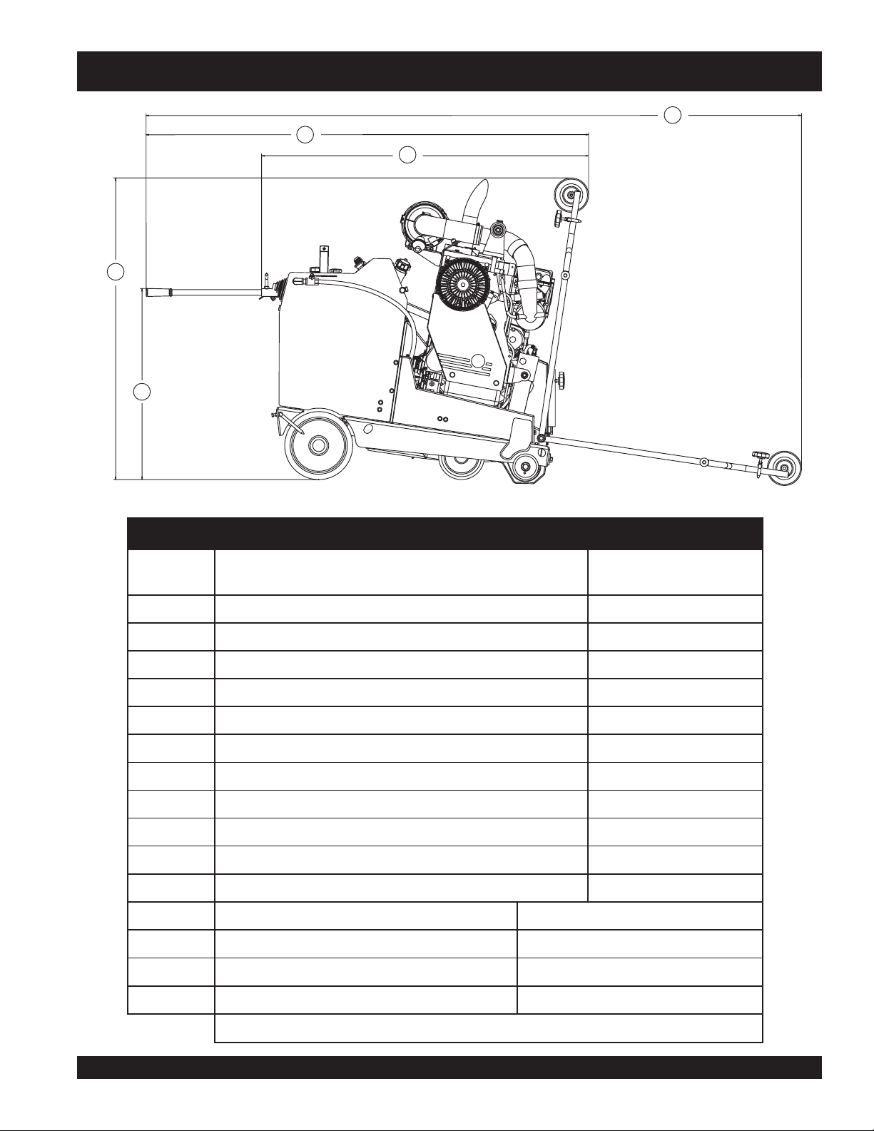
PS7060 MULTIQUIP SAW — DIMENSIONS
E
C
D
A
B
Figure 1. Chassis & Dimensions - Sideview
SNOISNEMID&SISSAHC.1ELBAT
ECNEREFER
RETTEL
A
B
C
D
E
F htdiWxaM )mm819(.ni8/1-63
G htdiWemarF )mm567(.ni8/1-03
H htgneLemarF )mm0721(.ni05
I htdiWleehWtnorF )mm517(.ni8/1-82
J htdiWleehWraeR )mm517(.ni8/1-82
K htdiWegnalFrennIotegnalFrennItfahSedalB )mm558(.ni8/5-33
thgieHraBeldnaHxaM )mm748(.ni8/3-33
NOITPIRCSED
)desiarretnioPtnorF(thgieHxaM )mm5331(.ni8/5-25
)desiaryllufretnioPtnorF&dellatsnIsraBeldnaH(htgneLxaM )mm2691(.ni4/1-77
)desiaryllufretnioPtnorF&dellatsnItonsraBeldnaH(htgneL )mm0541(.ni8/1-75
)derewolretnioPtnorF&dellatsnIsraBeldnaH(htgneLxaM )mm1092(.ni4/1-411
SNOISNEMID
)mm(.ni
srabeldnaH metsySrabeldnaHleveL-yatS
gnitnuoMelosnoC metsySlortnoCnoitarbiV
sissahC noitcurtsnoCxoBdedleWdemroF-dloC
thgiLthgiN lanoitpO
)mm5261x0901x5251(.ni46x34x06:)HxWxL(noisnemiDdetarC
PS7060 MULTIQUIP SAW • OPERATION MANUAL — REV. #2 (06/02/08) — PAGE 5
Page 6
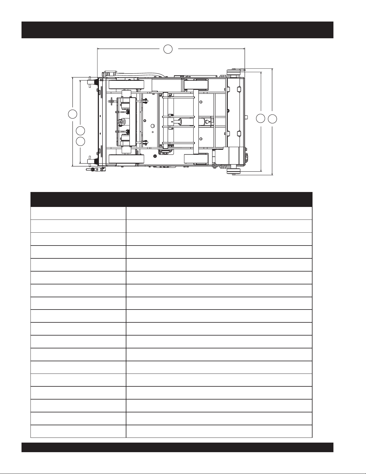
PS7060 MULTIQUIP SAW — SPECIFICATIONS
H
G
K
F
I
J
Figure 2. Chassis & Dimensions - Bottomview
SNOITACIFICEPSTFAHSDNAEDALB.2ELBAT
ylbmessAtfahSedalB
sgniraeBtfahSedalB
.ni8/3-2
(
retemaiDtfahSedalB
.ni1
retemaiDrobrA
segnalFedalB
2/1-4
seziSegnalFedalB
.ni
(
dna6
.ni
)mm06
)mm4.52
411(
mm
dna251
gnisuohnoritsacdesolcneylluf,ngisedhtabliO
stnemeriuqernoitacirbulon,detacirbulliO
tfahsotdetnuomsegnalfrenni,metsystcennocsidkciuQ
)mm
stleBevirD
thgieHesiaRedalB.xaM
gnitnuoMedalB
retemaiDedalB.xaM
tuCfohtpeD.xaM
yticapaCdrauGedalB
drauGedalB
rewoL-esiaRedalB
hctulCtfahSedalB
lortnoChctulCtfahSedalB
lortnoCretaW
noitubirtsiDretaW
PAGE 6 — PS7060 MULTIQUIP SAW • OPERATION MANUAL — REV. #2 (06/02/08)
)mm805(.ni02
thgiRrotfeL
)mm419(.ni63
)mm183(.ni51
tnuomderepat,no-pilS
pmupciluardyh-ortcelE
dradnatS
sevlavretawlauD
stlebevoorg-itlum035-XV3G5)2(,stleb01
)mm419-mm604(.ni63-61
edalbotretawreviledyltceridsenilretawlauD
metsysgninoisnetciluardyhybdellortnocyllacitamotuanoisnetevirdtleB
Page 7

PS7060 MULTIQUIP SAW — ENGINE SPECIFICATIONS
SNOITACIFICEPSROTOM/ENIGNE.3ELBAT
erutcafunaMenignE ztueD
ledoM
MPRxaM
rewopesroH
/
leuF
WkxaM
euqroTkaeP
yticapaCleuF
retliFriA
yticapaCliO
tnalooCenignE
1102L3FB
0003
2.06
/
9.44
.tf-bl4.331
/
snollag52.8
strauq8
/
mN181
leseiD
/
L2.13
renaelc-erpobrutlargetnihtiwlaeslaidartnemelelauD
L5.7
riAotliO
SNOITACIFICEPSMETSYSNOISSIMSNART.4ELBAT
pmuPnoissimsnarT
srotoMleehW
pmupnoissimsnartcitatsordyhraeg-ordyH
srotomleehwcitatsordyhraeg-ordyH
deepSlevarT
sekarB
ni3xni21
raeRsleehW
tnorFsleehW
(.
.ni3xni8
(
elbairavyletinifni,MPM48-0/MPF572-0
ekarbgnikrapgnitautcacitamotuA
)mm67xmm503
)mm67xmm302
STHGIEW.5ELBAT
thgieWdetarcnU
thgieWdetarC
)gK287(.sbl5271
)gK8.728(.sbl5281
PS7060 MULTIQUIP SAW • OPERATION MANUAL — REV. #2 (06/02/08) — PAGE 7
Page 8

TRAINING CHECKLIST
This checklist lists the minimum requirements for machine
maintenance and operation. Please feel free to detach it and
make copies. Use this checklist when training a new operator or
use as a review for more experienced operators.
.ON NOITPIRCSED ?KO ETAD
1 .yletelpmoclaunaMs’rotarepOdaeR
2 .slevelliociluardyhdnaenignefognikcehc,stnenopmocfonoitacol,tuoyalenihcaM
3 .erudecorpgnileufer,metsysleuF
4 .sthgildnayarpsfonoitarepO
5 .)gninnurtonenihcam(slortnocfonoitarepO
6 .noitarepohctiwspotsytefas,slortnocytefaS
TRAINING CHECKLIST
TSILKCEHCGNINIART
7 .serudecorppotsycnegremE
8 .ekohcenigne,taeh-erp,enihcamfoputratS
9 .levarTesreveRdnadrawroF
01 .tucagnitratS
11 .seuqinhcetgnittuCtnemevaP
21 .tucagnippotS
31 .noitanalpxe-ecafruskrownihtiwedalbgnippotsretfatrats-eR
41 .enihcamfonwodtuhS
51 .)spooltfil(enihcamfognitfiL
61 .egarotsdnatropsnartenihcaM
Operator _________________________________________ Trainee __________________________________________
COMMENTS:
PAGE 8 — PS7060 MULTIQUIP SAW • OPERATION MANUAL — REV. #2 (06/02/08)
Page 9

DAILY PRE-OPERATION CHECKLIST
1 .kcehcegamaddnaerawdraH
2 .levellioenignE
3 .levelliociluardyH
4 .edalbfonoitidnoC
DAILY PRE-OPERATION CHECKLIST
TSILKCEHCNOITAREPO-ERPYLIAD
5 efaS
6 .noitarepolortnocgnikarB
COMMENTS:
t
.noitarepohctiwSpotSy
PS7060 MULTIQUIP SAW • OPERATION MANUAL — REV. #2 (06/02/08) — PAGE 9
Page 10
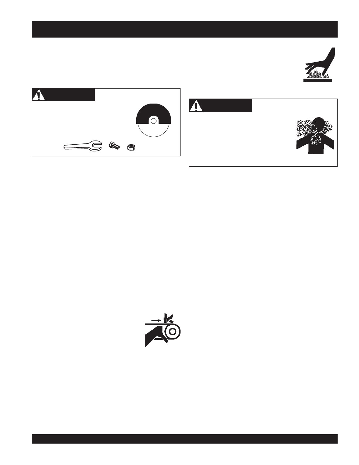
SAFETY MESSAGE ALERT SYMBOLS
FOR YOUR SAFETY AND THE SAFETY OF OTHERS!
Safety precautions should be followed at all times when
operating this equipment. Failure to read, understand and
comply with the Safety Messages and Operating Instructions
could result in injury to yourself and others.
This Operation Manual has been
developed to provide instructions for the
safe and efficient operation of the PS7060
MULTIQUIP Saw . For engine maintenance
information, please refer to the engine
manufacturer's instructions for data relative
to its safe operation.
Before using this Saw, ensure that the operating individual
has read, understands, and complies with all instructions
in this manual.
SAFETY MESSAGE ALERT SYMBOLS
The three (3) Safety Messages shown below will inform you
about potential hazards that could injure you or others. The
Safety Messages specifically address the level of exposure to
the operator, and are preceded by one of three words: DANGER,
WARNING, or CAUTION.
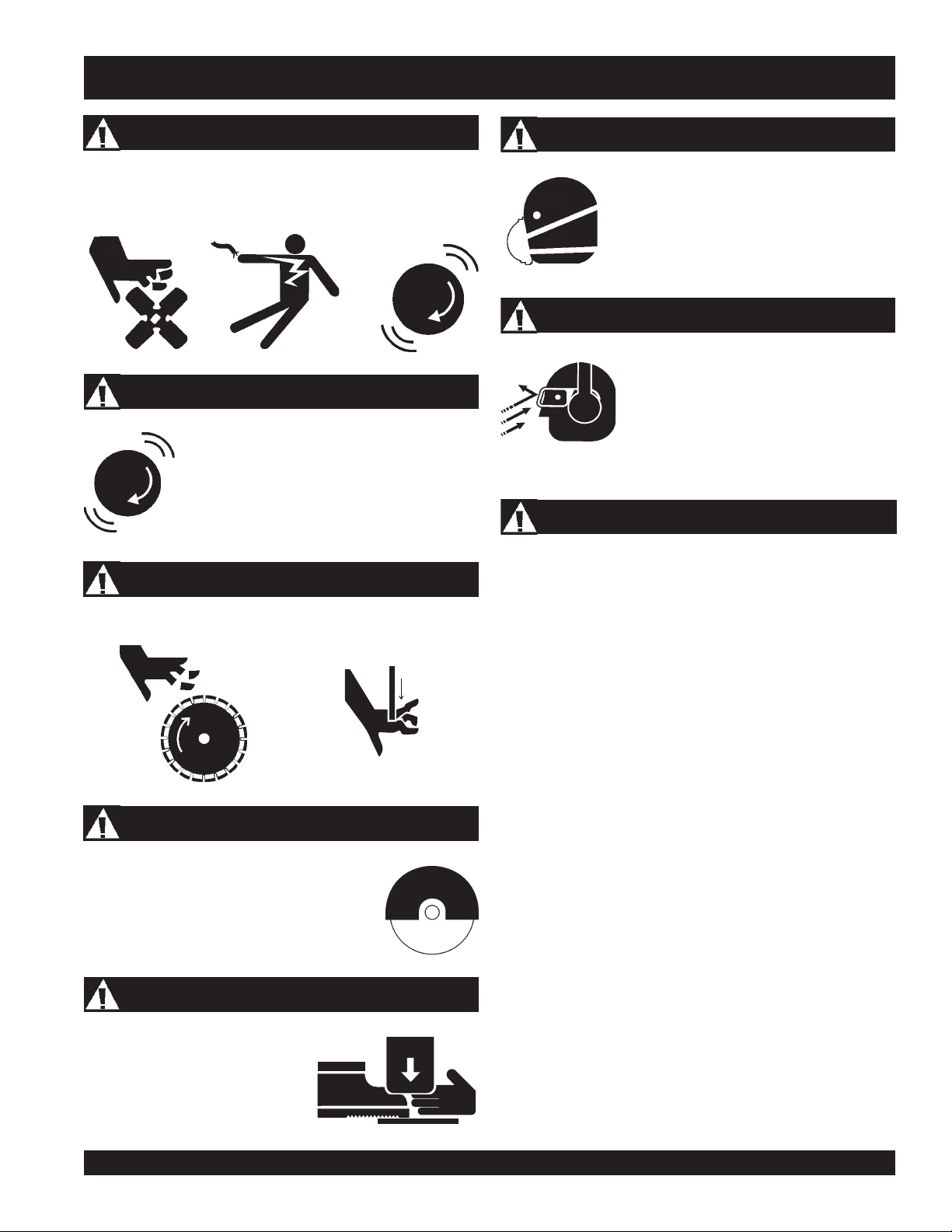
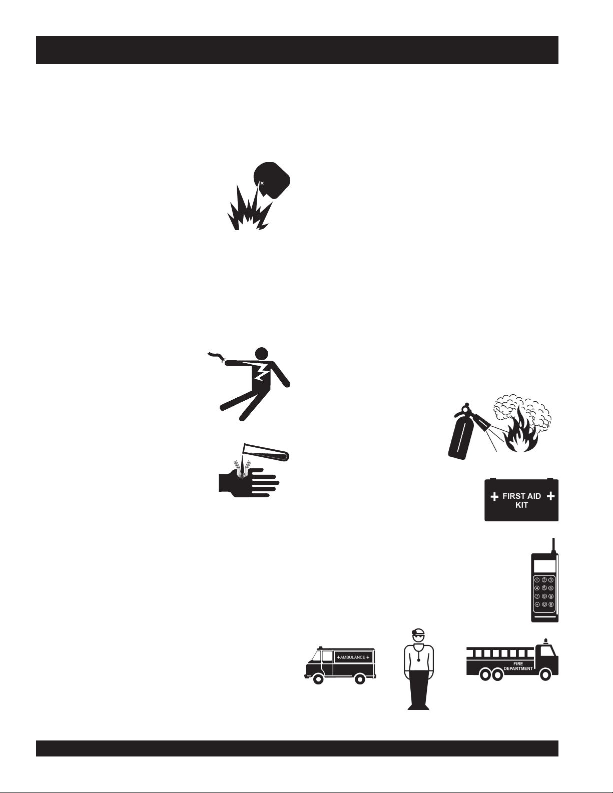
HAZARD SYMBOLS
Lethal Exhaust Gases
Engine exhaust gases contain harmful toxins
and will displace oxygen when running in an
enclosed or confined area. NEVER operate
this equipment in a confined area or enclosed
structure that does not provide ample free flow
air.
Explosive Fuel
Diesel fuel is flammable, and its vapors can
cause an explosion if ignited. DO NOT start
the engine near spilled fuel or combustible
fluids. DO NOT fill the fuel tank while the
engine is running or hot. DO NOT overfill
tank, since spilled fuel could ignite if it comes
into contact with hot engine parts or sparks
from the ignition system. Store fuel in
approved containers, in well-ventilated areas
and away from sparks and flames. NEVER
use fuel as a cleaning agent.
DANGERDANGER
DANGER
DANGERDANGER
You WILL be
if you DO NOT follow these directions.
WARNINGWARNING
WARNING
WARNINGWARNING
You CAN be KILLED or
you DO NOT follow these directions.
CAUTICAUTI
CAUTION
CAUTICAUTI
You CAN be
these directions.
Potential hazards associated with Saw operation will be
referenced with Hazard Symbols which appear throughout this
manual, and will be referenced in conjunction with Safety
Message Alert Symbols.
KILLED
INJURED
or
SERIOUSLY INJURED
SERIOUSLY INJURED
if you DO NOT follow
if
Burn Hazards
Engine components can generate extreme heat.
To prevent burns, DO NOT touch these areas
while the engine is running or immediately after
operations. NEVER operate the engine with
heat shields or heat guards removed.
Rotating Parts
NEVER operate equipment with covers, or
guards removed. Keep
and
clothing
prevent injury.
Skin Injection Hazard
NEVER use your hand to find hydraulic leaks.
Use a piece of wood or cardboard. Hydraulic
fluid injected into the skin must be treated by a
knowledgable physician immediately or severe
injury or death can occur.
away from all moving parts to
fingers, hands, hair
PAGE 10 — PS7060 MULTIQUIP SAW • OPERATION MANUAL — REV. #2 (06/02/08)
Page 11
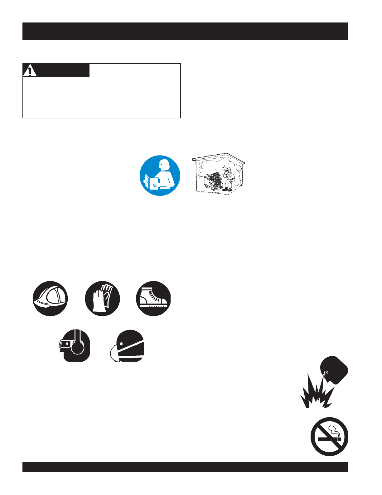
SAFETY MESSAGE ALERT SYMBOLS
Accidental Starting
Accidental starts can cause severe injury or death. ALWAYS
place the ON/OFF switch in the OFF position. Disconnect
negative battery cable from battery before servicing.
Over Speed Conditions
NEVER tamper with the factory settings of the
engine governor or settings. Personal injury
and damage to the engine or equipment can
result if operating in speed ranges above
maximum allowable.
Rotating Blade
Rotating blade can cut and crush. Keep hands and feet clear.
Other important messages are provided throughout this manual
to help prevent damage to your saw, other property, or the
surrounding environment.
Respiratory Hazard
ALWAYS wear approved respiratory
protection.
Sight and Hearing hazard
ALWAYS wear approved eye and hearing
protection.
Equipment Damage Messages
Guards and Covers In Place
NEVER operate the saw without blade guards
and covers in place. Adhere to safety
guidelines and applicable local regulations.
Crush Hazard
ALWAYS ensure saw is
SECURELY placed on appropriate
blocks or jackstands when
performing maintenance requiring
the saw to be elevated.
PS7060 MULTIQUIP SAW • OPERATION MANUAL — REV. #2 (06/02/08) — PAGE 11
Page 12
PS7060 MULTIQUIP SAW — RULES FOR SAFE OPERATION
■
RULES FOR SAFE OPERATION
WARNINGWARNING
WARNING
WARNINGWARNING
Failure to follow instructions in this manual may lead to serious
injury or even death! This equipment is to be operated by
trained and qualified personnel only! This equipment is for
industrial use only.
The following safety guidelines should always be used when
operating the PS7060 MULTIQUIP SAW .
SAFETY
■
DO NOT operate or service this
equipment before you read, understand,
and comply with all safety messages in
this manual. The manual must be kept
available and accessible to the operator.
■
This equipment should not be operated by persons under the
minimum statutory age limit.
■
NEVER use this machine for any purpose other than those
described in this manual.
NEVER operate this equipment when not feeling well due to
fatigue, illness or taking medicine.
■
NEVER operate the saw under the influence of drugs or alcohol.
■
AVOID wearing jewelry or loose fitting clothing that may snag
on the controls or moving parts, this can cause a serious
injury.
■
Replace operation and safety decals when they become
difficult to read.
■
The engine of this saw requires an adequate free flow of
cooling air. NEVER operate the saw in any enclosed or narrow
■
Make certain the operator knows how to and is capable of
turning the engine OFF in case of an emergency.
■
Turn engine OFF prior to fueling the saw.
area where free flow of the air is
restricted. If the air flow is restricted it
will cause serious damage to the
engine and may cause injury to people.
Remember the engine can give off
harmful toxins and will displace
oxygen.
■
NEVER operate the saw without proper protective clothing,
shatterproof glasses, steel-toed boots and other protective
devices required for the job.
■
NEVER use accessories or attachments which are not
recommended by the manufacturer for this equipment.
Damage to the equipment and/or injury to user may result.
■
Manufacturer does not assume responsibility for any accident
due to equipment modifications. Unauthorized equipment
modification will void all warranties. Any modification which
could lead to a change in the original characteristics of the
machine should be made only by the manufacturer who shall
confirm that the machine is in conformity with appropriate
safety regulations.
■
■
■
■
■
■
ALWAYS refuel in a well-ventilated area, away from sparks
and open flames.
Topping-off to filler port is dangerous, as it tends to spill fuel.
NEVER use fuel as a cleaning agent.
ALWAYS use extreme caution when working with flammable
liquids. Allow the engine to cool before adding fuel or
performing service and maintenance functions.
NEVER operate the saw in an
explosive atmosphere where fumes
are present, or near combustible
materials. An explosion or fire could
result in severe
death.
NEVER
Fire or explosion could result from
vapors
smoke
, or if fuel is spilled on a
bodily harm or even
around or near the machine.
fuel
hot!
engine.
PAGE 12 — PS7060 MULTIQUIP SAW • OPERATION MANUAL — REV. #2 (06/02/08)
Page 13
PS7060 MULTIQUIP SAW — RULES FOR SAFE OPERATION
■
ALWAYS keep the work area well organized.
■
Keep the saw clean. It will perform better and last longer.
■
ALWAYS Clear the cutting area of any debris, tools, etc. that
would constitute a hazard while the saw is in operation.
WARNINGWARNING
WARNING
WARNINGWARNING
ALWAYS check to make sure that the
cutting area is clear before starting the
engine.
■
Keep all inexperienced and unauthorized people clear of
the cutting area when operating the saw.
■
No one other than the operator is to be in the working area
when the saw is in operation.
■
NEVER allow passengers or riders on the saw during
operation or transportation.
■
ALWAYS check the saw for loosened hardware such as nuts
and bolts before starting.
■
■
■
■
NEVER touch the hot exhaust manifold, muffler
or cylinder. Allow these parts to cool before
servicing the saw. Contact with
components can cause serious burns.
DANGERDANGER
DANGER
DANGERDANGER
Pay close attention to ventilation when
operating the saw in confined spaces such
as tunnels, buildings or similar areas. The
engine exhaust contains harmful elements.
Ensure proper air flow to move engine
exhaust away from the operator.
Verify the engine start switch is set to the OFF position before
installing a blade.
Use proper blades and follow the blade manufacturer's
recommendations. Match the blade RPM (Blade Shaft RPM)
to the recommended blade surface feet per minute. (SFPM).
Ensure the 5/8" blade-mounting bolt is tightened to 125-175
foot lbs. of torque.
hot!
■
NEVER run the engine without the air filter. Severe engine
damage could occur. Service air cleaner at recommended
service intervals to prevent engine damage.
■
Make certain all protective guards are securely in place
BEFORE operating the saw. This saw is supplied with a blade
guard, blade flange guard, and a belt guard.
■
NEVER place your
starting or operating this equipment.
■
DO NOT go near rotating parts, (blades,
belts, pulleys or wheels), while engine is
running.
■
Moving Parts – Shut down the engine before performing
service or maintenance functions. Contact with moving parts
can cause serious injury.
feet
or
hands
inside the guards while
■
■
■
■
■
■
NEVER leave the machine
Ensure brakes are applied when leaving or when using on a
slope. This saw utilizes a brake system where the brakes are
automatically applied when the engine is stopped.
Start engine with the Control Handle in the NEUTRAL
position to prevent unexpected saw movement.
Do not start engine on a sloping surface to prevent
unexpected loss of control.
DO NOT use on excessive slopes or on extremely uneven
surfaces.
If the saw must be parked on a slope and engine turned off,
ensure the parking brake is engaged and holds the saw
safely in place. Turning the saw across the angle of the slope
will help prevent accidental downhill movement. Block the
saw as well when leaving.
unattended
while running.
PS7060 MULTIQUIP SAW • OPERATION MANUAL — REV. #2 (06/02/08) — PAGE 13
Page 14

PS7060 MULTIQUIP SAW — RULES FOR SAFE OPERATION
■
Always store equipment properly when not being used.
Equipment should be stored in a clean, dry location out of
the reach of children. When storing the saw in freezing
weather, blow out the water lines to prevent damage to
components in the water delivery system.
■
DON'T POLLUTE! Waste Oils and other chemicals must be
disposed of in a manner consistent with local and state
environmental protection regulations.
■
Always observe all applicable compulsory regulations
relevant to environmental protection, especially fuel storage,
the handling of hazardous substances, and the wearing of
protective clothing and equipment. Instruct the user as
necessary, or, as the user, request this information and
training.
Diamond Blade Safety
■
■
■
Use appropriate steel-centered diamond blades
manufactured for particular use on your saw. See further
blade information in this manual.
WARNINGWARNING
WARNING
WARNINGWARNING
ALWAYS inspect diamond blades
before each use. The blade should
exhibit no cracks, dings, or flaws in
the steel centered core and/or rim.
Center (arbor) hole must be
undamaged and true.
Examine blade flanges for damage and excessive wear.
Ensure the cleanliness of the blade before blade is installed.
Blade should fit snugly on the shaft and against the inside/
outside blade flanges.
■
Ensure the blade is marked with an operating speed greater
than the spindle speed of the saw.
■
Only cut the material that is specified for the diamond blade.
Read the specifications of the diamond blade to ensure the
proper tool has been matched to the material being cut. The
saw has been engineered for WET CUTTING. Ensure a
WET CUTTING blade is being used and that the water supply
system to the blade is properly functioning and being used.
■
ALWAYS keep blade guards in place. Exposure of the
diamond blade must not exceed 180 degrees.
■
Ensure that the diamond blade does not come into contact
with the ground or surface during transportation. DO NOT
drop the diamond blade on ground or surface.
■
The engine governor is set to permit maximum engine speed
in a no-load condition. Do not tamper with the engine
governor to increase the speed. Increasing the engine speed
could allow the maximum rated spindle speed to be
exceeded, creating an unsafe condition.
■
Ensure that the blade is mounted for proper operating
direction.
■
Adhere to the Blade Manufacturer's recommendations on
handling, storage, and safe usage of blades.
PAGE 14 — PS7060 MULTIQUIP SAW • OPERATION MANUAL — REV. #2 (06/02/08)
Page 15

PS7060 MULTIQUIP SAW — RULES FOR SAFE OPERATION
Saw Lifting and Loading Safety
CAUTIONCAUTION
CAUTION
CAUTIONCAUTION
This Saw is very
and DO NOT attempt to lift the by the guards.
DANGERDANGER
DANGER
DANGERDANGER
NEVER stand under or allow anyone else to stand under the
saw while it is being lifted.
■
DO NOT use the handle bars and/or front pointer as lifting
points.
■
ALWAYS use ramps capable of supporting the weight of the
saw and the operator to load and unload the saw. If the saw
must be lifted, always use two people. Never attempt to lift
the saw by yourself.
■
NEVER tip the engine to extreme angles as it may cause oil
to gravitate into the cylinder head making the engine start
difficult.
■
NEVER transport the saw to or from the job site with the
blade mounted.
heavy
. Use proper heavy lifting procedures
Towing Safety Precautions (Trailer Usage)
To reduce the possibility of an accident while transporting the
saw on public roads, always make sure the trailer that supports
the saw and the towing vehicle are in good operating condition
and both units are mechanically sound.
The following list of suggestions should be used when towing
your saw:
■
■
■
■
CAUTIONCAUTION
CAUTION
CAUTIONCAUTION
Conform to
Towing Regulations
roads.
Check the tire air pressure on both towing vehicle and trailer.
Refer to the tire manufacturer's recommended pressure. Also
check the tire tread wear on both vehicles.
Make sure the hitch and coupling of the towing vehicle are
rated equal to, or greater than the trailer "gross vehicle weight
rating" (GVWR) of 6,000 lbs.
ALWAYS inspect the hitch and coupling for wear. NEVER
tow a trailer with defective hitches, couplings, chains, etc.
ALWAYS make sure the trailer is equipped with "Safety
Chains " and ensure they are attached properly.
Department of Transportation (DOT) Safety
before transporting saw on public
Transporting (Via truck/trailer)
■
ALWAYS shutdown engine before transporting.
■
Tighten fuel tank cap securely and close fuel petcock to
prevent fuel from spilling.
■
Drain fuel when transporting saw for long distances or over
bad roads.
■
Use appropriate lifting equipment to ensure the safe
movement of the saw.
■
Do not use the handlebars or front pointer as lifting points.
■
When placing the saw on a truck-bed for transport,
tie-down the saw.
■
Do not use the handlebars or front pointer as tie-down points.
■
Never attempt to tow the saw untrailered behind a vehicle.
■
Never transport the saw with the blade mounted.
■
If the saw is being transported via a trailer, make sure the
trailer complies with all local and state safety transportation
laws. Refer to the following "
for basic towing techniques.
Towing Safety Precautions"
always
■
■
■
■
■
■
■
■
■
ALWAYS make sure the vehicle and trailer directional,
backup, brake, and trailer lights are connected and working
DO NOT exceed the recommended highway speed when
towing.
Use chock-blocks at each wheel when parked to prevent
trailer from rolling.
Use the trailer's swivel jack to adjust the trailer height to a
level position while parked.
Avoid sudden stops and starts. This can cause the trailer to
skid or jack-knife. Smooth, gradual starts and stops will
improve towing.
Avoid sharp turns.
Trailer should be adjusted to a level position at all times
when towing.
Raise and lock trailer wheel stand in the "UP" position when
transporting.
DOT requirements include the following:
Connect and test electric brake operation.
Secure portable power cables in cable tray with tie wraps.
PS7060 MULTIQUIP SAW • OPERATION MANUAL — REV. #2 (06/02/08) — PAGE 15
Page 16
PS7060 MULTIQUIP SAW — RULES FOR SAFE OPERATION
Battery
The battery contains acids that can cause injury to the eyes and
skin. To avoid eye irritation,
shielding. Use well insulated gloves when picking the battery
up. Use the following guidelines when handling the battery.
■
DO NOT drop the battery. Any impact to
the battery may cause it to explode.
■
DO NOT expose the battery to open flames,
sparks, lit cigarettes etc. The battery
contains combustible gases and liquids. If
these gases and liquids come in contact
with a flame or spark an explosion can occur.
■
ALWAYS keep the battery charged. If the battery is not
charged a buildup of combustible gas will occur.
■
ALWAYS recharge the battery in a vented air environment
to avoid risk of a dangerous concentration of combustible
gases.
■
ALWAYS keep battery cables in good working condition.
Repair or replace all worn cables.
■
Disconnect battery cables before
inspecting electrical system and
never "spark" battery terminals to test
for charge.
always
wear safety glasses or face
■
ALWAYS allow the saw a proper amount of time to cool
before servicing.
■
Prior to service, level the frame surface.
■
Anytime the saw is lifted onto its nose, or tilted fully back such
as for maintenance access, the high end of the saw MUST
be blocked up to prevent the possibility of crush injury.
■
Make sure that there is no buildup of concrete, grease, oil or
debris on the machine.
■
Repair damage to the saw immediately and always replace
broken parts.
■
Dispose of hazardous waste properly. Examples of potentially
hazardous waste are used motor oil, fuel and fuel filters.
■
DO NOT use plastic food containers to dispose of hazardous
waste.
■
DO NOT pour waste oil or fuel directly onto the ground, down
a drain or into any water source.
■
NEVER store saw with fuel in the tank for any extended period
of time. Always clean up spilled fuel immediately.
Emergencies
■
In case the battery liquid (dilute
sulfuric acid), comes in contact with
clothing or skin
immediately with plenty of water.
■
In case the battery liquid, (dilute sulfuric
acid), comes in contact with your
rinse eyes immediately with plenty of water, then contact the
nearest doctor or hospital and seek medical attention.
Maintenance Safety
■
Maintain this equipment in a safe operating condition at all
times.
■
ALWAYS shut down the engine and disconnect battery before
performing service or maintenance functions. Contact with
moving parts can cause serious injury.
■
Securely support any saw components that must be raised.
■
NEVER lubricate components or attempt service on a running
saw.
, rinse skin or clothing
eyes
,
■
■
■
ALWAYS know the location of
the nearest
ALWAYS know the location of the
nearest
Know the phone numbers of the nearest
ambulance, doctor
that a phone or radio is readily available at the
jobsite. If this is not possible, know the location of
the nearest phone. This information will be
invaluable in the event of an emergency.
fire extinguisher
first aid kit
.
and
.
fire department
. Ensure
PAGE 16 — PS7060 MULTIQUIP SAW • OPERATION MANUAL — REV. #2 (06/02/08)
Page 17

PS7060 MULTIQUIP SAW — INTENDED USE / FAMILIARIZATION
Intended Use
Operate the PS7060 MULTIQUIP SAW, tools and components
in accordance with the manufacturer's instructions. Use of any
other tools for stated operation is considered contrary to
designated use. The risk of such use lies entirely with the user.
The manufacturer cannot be held liable for damages as a result
of misuse.
This saw is not intended for dry cutting.
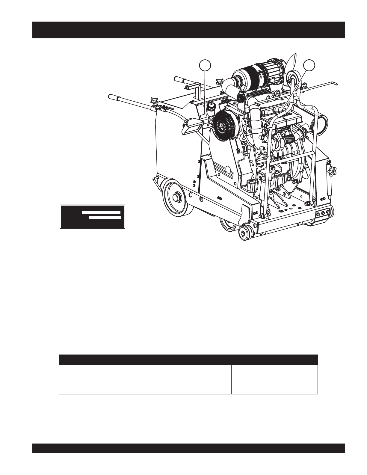
Engine
The PS7060 saw is classified in the industry as a "high" powered
saw. This classification is particularly useful when selecting the
proper cutting tool (blade) for an application.
The PS7060 saw is powered by a liquid cooled, 3 cylnder,
turbocharged diesel engine rated at 60.2 HP (44.9 kW) at 3,000
RPM. Blade rotation is belt driven. Wheel Drive system is driven
by a hydrostatic transmission consisting of a variable
displacement pump and two fixed displacement wheel motors.
Refer to the
regarding engine operation and maintenance practices.
Engine Owner's Manual
for specific instructions
Features
■
Stay-Level handlebar system adjusts handlebar angle
automatically.
■
Engine Stop Switch conveniently located on Operators
Control Panel.
■
Console mounted with Vibration Control System.
■
Chassis cold-formed welded box construction.
■
Oil lubricated Blade Shaft Bearings - no lubrication
requirements.
■
Oil Bath design, fully enclosed cast iron housing.
■
Quick Disconnect Blade Flange system; inner flanges
mounted to shaft.
■
Blade mounting Left side or Right side.
■
Saw position guide helps ensure straight cuts
■
Dual water lines directly deliver water to blade.
■
Slip-On, tapered mount Blade Guard for ease of removal
and installation.
■
Blade Raise-Lower by electro-hydraulic pump.
■
Belt Drive tension automatically controlled by hydraulic
tensioning system.
■
Water System
All PS7060 saws provide a hardy water plumbing system that
evenly distributes water volume and optimum flow rate to both
sides of the blade to keep it cool when cutting. The basic water
system provides a valve that connects to a standard garden hose.
The water is delivered (via a hose) to the saw blade.
All MULTIQUIP PS7060 saws are designed, engineered and
manufactured with strict adherence to American National
Standards Institute, Inc. (ANSI) guidelines B7.1 and B7.5.
Dual Filter Element Air Filter with integral turbo pre-cleaner.
■
Hydro-gear hydrostatic transmission pump.
■
Hydro-gear hydrostatic wheel motors.
■
Travel Speed up to 84 MPM (meters per minute)/ 275 FPM.
■
Automatic actuating parking brake.
■
Optional Night Light.
PS7060 MULTIQUIP SAW • OPERATION MANUAL — REV. #2 (06/02/08) — PAGE 17
Page 18

NOTES
PAGE 18 — PS7060 MULTIQUIP SAW • OPERATION MANUAL — REV. #2 (06/02/08)
Page 19
1
2
PS7060 MULTIQUIP SAW — SERIAL TAG INFORMATION
MODEL
SERIAL NO.
Figure 4. Serial Tag/Locations
Serial Tag
The serial tag contains the model number and serial number of
the saw. The information details all parts that were included with
the saw when it was shipped from the factory, as well as the date
of manufacture.
The SERIAL TAG is bonded to the inside of the console. (Item 1,
Figure 4.)
Record these numbers, in case you need to contact the
manufacturer for information or service in the future.
Record your ENGINE model, (Item 2) specification number and
serial number here:
REBMUNLEDOM REBMUNLAIRES REBMUNENIGNE
noitamrofnIgaTlaireS.6elbaT
PS7060 MULTIQUIP SAW • OPERATION MANUAL — REV. #2 (06/02/08) — PAGE 19
Page 20
PS7060 MULTIQUIP SAW — CONTROLS AND INDICATORS
INCH
MM
0
25
50
0
1
2
3
75
100
125
150
175
200
230
255
280
305
330
355
380
15
9
10
11
12
13
14
4
5
6
7
8
4
8
9
10
16
6
7
15
5
14
17
3
13
12
11
2
1
18
Figure 5. PS7060 MULTIQUIP SAW Controls and Indicators
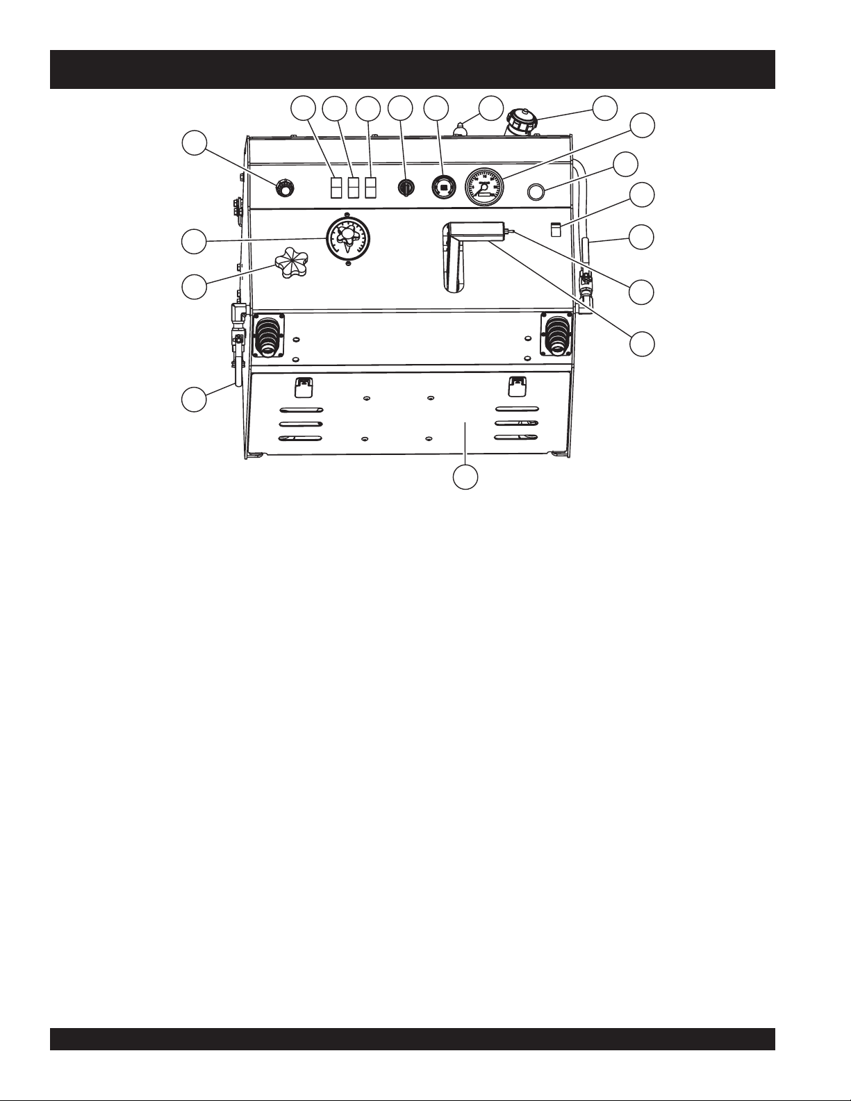
Figures 5 and 6 show the location of the controls, indicators and
9. Depth Stop –
general maintenance parts. The function of each control, indicator
or maintenance part is explained below:
1. FNR Handle – Use to engage the saw in a forward or
backward direction. Push handle forward to move the saw
forward; pull handle back to move saw backward.
2. Raise/Lower Switch –
Use to lift or lower the front of the
saw (and blade if installed).
3. Bladeshaft RPM –
Indicates bladeshaft speed in
revolutions per minute.
4. Throttle Control – Controls the speed of the engine.
Tu r n
knob counter-clockwise to increase engine speed. Turn
knob clockwise to reduce engine speed. For quick throttle
response, depress red button and push or pull knob.
5. System Status – Allows operator to monitor engine and
electrical functions.
6. Ignition Switch – With key inserted turn clockwise to start
10. Left Water Flow Valve – Meters water supply.
11. Right Water Flow Valve – Opens and closes water supply
to water supply system.
12. Water Pump Switch (Optional) –
or off.
13. Emergency Stop Button – Press the RED Emergency
Stop Button to shut the system down.
14. Socket Connector – Use to plug in optional light.
15. Blade Shaft Engage/Dis-engage Switch – Toggle switch
to engage or dis-engage the blade shaft drive.
16. Auxiliary Switch –
17. Fuel Filler Cap – Remove this cap to add fuel.
18. Rear Access Panel –
the battery, hydraulic filter, etc.
engine.
Allows repeatable cutting depths.
Toggle to turn pump on
Remove to access items such as
7. Light Switch – When activated, turns on light. Lights offer
better visibility when working indoors.
8. Depth Indicator – Indicates relative depth of blade in
surface.
PAGE 20 — PS7060 MULTIQUIP SAW • OPERATION MANUAL — REV. #2 (06/02/08)
Page 21

14
PS7060 MULTIQUIP SAW — COMPONENTS
15
1
16
2
13
10
12
11
23
1. Front Pointer Assembly
2. Blade Wrench
3. Bladeshaft Pulley Guard
4. Bladeshaft Assembly
5. Blade Flange
6. Front Axle Assembly
7. Left Wheel Motor
8. Brake Cylinder
9. Right Wheel Motor
10. Engine Guard
11. Rear Pointer
8
9
7
21
3
4
6
20
22
5
Figure 6. PS7060 MULTIQUIP SAW Components
13. Rightside Water On/Off Control Valve
14. Light Assembly
15. Engine Assembly
16. Engine Fuel Filler Cap
17. Control and Indicator Panel
18. Stay-Level Handles (SLH)
19. Rear Access Panel
20. Flange Guard
21. Leftside Water Metering Valve
22. Belt Guard
23. Slurry Strip
17
18
19
12. Documentation Box
PS7060 MULTIQUIP SAW • OPERATION MANUAL — REV. #2 (06/02/08) — PAGE 21
Page 22

PS7060 MULTIQUIP SAW — BASIC ENGINE INFORMATION
4
1
3
11
2
18
15
13
12
8
6
9
16
17
10
7
14
5
Figure 7. Basic Engine Components
Basic Engine Components
The following refer to basic engine components and their functions
that an operator may need to reference . The manufacturer's engine
manual provides further instructions and details of operation and
servicing. The engine shown in Figure 7 is a Deutz BF3L2011
engine.
1. Fuel Filter – Removes dirt and water from the engine fuel.
2. Governor Lever – This lever restricts engine speed (high
idle and low idle) through a speed control device linked to
the accelerator system.
3. Oil Dip Stick – Remove to check amount and condition of
oil in crankcase.
4. Oil Filter – Spin-on type, filters oil for contaminants.
5. Oil Drain Plug & Hose – Remove plug and attach drain
hose to drain crankcase oil.
6. Oil Filler Port – Remove to add fresh crankcase oil.
7. Crankshaft V-Pulley – Check fan V-belt between V-Pulley
and fan to determine proper belt tension.
8. Cooling Fan – Driven by the V-belt, the cooling fan cools
the engine by cooling engine oil that circulates through the
engine block and cylinder head.
9. V-belt Tension Adjustment – This bolt provides means
to adjust the V-belt tension at the alternator bracket.
10. V-belt (Fan belt) – Driven by the engine crank during
operation, drives the fan as well as the aternator.
11. Oil Fill Cap – Remove to add engine oil.
12. Lifting Eye – The lifting eye is provided if the removal/
installation of the engine becomes necessary.
13. Alternator – Located inside the fan assembly. Provides
current to the electrical system and charges the battery.
Driven by means of a crankshaft/V-belt pulley system.
14. Starter – Starts engine when ignition key is rotated to the
"START" position.
15. Flywheel – Main power is taken off from the flywheel end.
16. Air Intake Port – Provides air from the air cleaner to the
turbocharger unit.
17. Turbocharger – Provides pressurized intake air to the
cylinder by means of a turbine energized by exhaust gas
that rotates the blower.
18. Air Cleaner Assembly – Provides clean filtered air to the
air intake port.
PAGE 22 — PS7060 MULTIQUIP SAW • OPERATION MANUAL — REV. #2 (06/02/08)
Page 23

PS7060 MULTIQUIP SAW — CHOOSING PROPER BLADE SIZE
Choosing Proper Blade Size
To select the proper size blade for the job requires an understanding
of the cutting capability of your saw and its relationship between
engine power, (as reflected in the engine RPM), and the speed
(RPM) of the Blade Shaft. The diesel engine of the PS7060 runs at
2800 RPM (full load). If 2800 RPM was a desirable Blade Shaft
speed for the average conditions in which you work, we would use
the same size sheave on the engine shaft and the blade shaft making
the resulting ratio between the two of 1:1. (See figure 8.)
2800 (engine RPM) / 2000 (desired BS RPM) = 1.4
This is the ratio 1.4 : 1, which means that for every 1.4 revolutions of
the engine, the Blade Shaft only turns once.
Ratios greater than 1 : 1 also have the beneficial effect of
the torque of the Blade Shaft
The manufacturer advertises the Deutz 2011 Series diesel engine
develops 133 ft. lbs. (max) of torque. To find the
Shaft torque of our example saw setup:
Actual torque of the saw will vary somewhat. In general, more torque
means more cutting power.
by the same factor (1.4 in our example).
133 x 1.4 = 186.2 ft. lbs.
increasing
theoretical
Blade
1 : 1 Ratio
Figure 8. Blade Shaft Ratios
If, however, for your cutting conditions, you need a Blade Shaft speed
slower than the engine speed (and this usually is the case), we then
need to INCREASE the ratio between the two speeds by using a
larger diameter sheave on the Blade Shaft, which will cause the
Blade Shaft to run slower than the engine speed. If, for example, you
know from experience that you need a Blade Shaft speed of 2000
RPM for the size of blade you normally use, divide the engine speed
RPM by the desired blade speed RPM (refer to the Blade RPM vs.
SFPM Chart, Table 7.)
1.4 : 1 Ratio
Typically, however, the ratios are not used to design a level of torque;
they are used to create optimum blade speed (Blade Shaft RPM) for
your application.
The major factors are:
■
diameter of blade(s) you commonly use
■
cutting conditions
PS7060 MULTIQUIP SAW • OPERATION MANUAL — REV. #2 (06/02/08) — PAGE 23
Page 24

PS7060 MULTIQUIP SAW — CHOOSING PROPER BLADE SIZE
Blade RPM vs. Surface Feet Per Minute (SFPM)
CAUTIONCAUTION
CAUTION
When choosing a blade for your cutting conditions, follow the blade
manufacturer's recommendations. Match the blade speed (Blade
Shaft RPM) to the recommended blade Surface Feet Per Minute
(SFPM) See table 7.
WARNINGWARNING
WARNING
WARNINGWARNING
Maximum allowable Blade Surface Feet Per Minute per ANSI
Standard B.7.1 is 16,000 SFPM.
Table 7. Optimum Blade RPM Range
CAUTIONCAUTION
Verify the engine start switch is OFF before removing or
installing a blade.
Tighten the 5/8" blade-mounting bolt to 125-175 ft. lbs. of
torque.
OPTIMUM
BLADE
RPM
RANGE
NEVER EXCEED BLADE MANUFACTURER'S RECOMMENDED RPM'S
16" BLADE
RPM
2149 1719 1322 1146 955
2388 1910 1469 1273 1061
2627 2101 1616 1401 1167
2865 2292 1763 1528 1273
3104 2483 1910 1655 1379
3343 2674 2057 1783 1486
20" BLADE
RPM
26" BLADE
RPM
30" BLADE
RPM
36" BLADE
RPM
SURFACE FEET
PER MINUTE
9,000 SFPM
10,000 SFPM
11,000 SFPM
12,000 SFPM
13,000 SFPM
14,000 SFPM
PAGE 24 — PS7060 MULTIQUIP SAW • OPERATION MANUAL — REV. #2 (06/02/08)
Page 25

PS7060 MULTIQUIP SAW — SPECIFIC TOOLS / SAW BLADES
SPECIFIC TOOLS TO BE USED
This saw is to use tools (blades) as follows:
Steel Core Segmented or Continuous Diamond Rim
Cutting Wheel.
Any other type of tool is not to be used.
WARNINGWARNING
WARNING
WARNINGWARNING
Failure to thoroughly inspect the diamond blade, (Figure 9)
for operational safety could result in damage to the blade or
the saw, and may cause injury to the user or others in the
operating area. Discard damaged or worn blades and
replace with fresh blade.
1. Drive Pin Hole – A commonly located hole on the diamond
2. Stress Relief Holes (Gullets) –
3. Edge Of The Steel Core – Check the diameter edge for
4. Directional Arrow – Check to ensure that the blade is
blade core that prevents operational blade slippage
between the inner & outer blade flanges (collars). Inspect
the diameter of the hole to ensure there is no distortion,
and that a snug fit develops between the hole and drive
pin.
Check the steel core for
cracks that may have propagated from the slots and/or
gullets. Cracks indicate extreme fatigue failure and if sawing
continues, catastrophic failure will occur.
discoloration (blue oxidation) indicating an overheating
condition caused by insufficient cooling water/air.
Overheating of blades may lead to loss of core tension
and/or increase the possibility for blade failure. Check to
make sure the steel core’s width is uniform about the rim of
the blade, and not succumbing to an “under cutting”
condition brought about by highly abrasive material or
improper under cutting core protection.
oriented properly on the spindle/arbor for sawing. Reference
the directional arrow on the blade and place it so the
direction of rotation “downcuts” with the turn of the shaft.
Figure 9. Diamond Blade
5. Diamond Segment or Rim – Ensure there are no cracks,
dings, or missing portions of the diamond segment/rim. DO
NOT
use a blade that is missing a segment or a portion
of
the rim
cause damage to your saw, and injury to the user or others
in the operating area.
6. Specifications – Ensure that the blade specifications, size,
and diameter properly match up to the sawing operation.
Wet blades must have water to act as a coolant. Utilizing a
diamond blade not matched properly to the task may result
in poor performance and/or blade damage.
7. Arbor Hole – It is essential that the arbor hole diameter
properly matches the shaft arbor, and that it is free from
distortions. Correct blade flanges (collars) must be used.
The inside face of the flanges must be clean & free of debris.
An out of round arbor condition will cause damage to the
blade and the saw.
8. MAX RPM – This RPM reference is the maximum safe
operating speed for the blade selected. NEVER exceed
the max RPM on the diamond blade. Exceeding the MAX
RPM is dangerous, and may cause poor performance and
may damage the blade. All blades used must be designed
for the maximum spindle RPM.
. Damaged and/or missing segments/rims may
PS7060 MULTIQUIP SAW • OPERATION MANUAL — REV. #2 (06/02/08) — PAGE 25
Page 26

PS7060 MULTIQUIP SAW — INSTALLING THE BLADE
Installing the Blade
The blade can be mounted on either side of the saw to accomodate
different cutting jobs. With the proper sized blade selected, install
the new blade referring to the following procedure.
Ensure the flange faces are kept clean and smooth
as well as the inside diameter of the Blade Shaft.
1. Raise the saw so the blade will clear the ground when
installed.
2. Remove the blade flange bolt. This bolt is LEFT-HAND
thread on the RIGHT side of the saw and RIGHT-HAND
thread on the LEFT side of the saw.
3. Verify the blade flanges are clean and not damaged. Pay
particular attention to all holes and recesses. Clean or "rodout" as necessary (Figure 10.)
Figure 10. Inspect and Clean Flange
Figure 11. Aligning Flange Pin Through Blade
WARNINGWARNING
WARNING
WARNINGWARNING
Failure to properly tighten the Blade Mounting Bolt can result
in the bolts coming loose with the Blade Flange potentially
falling off the rotating Blade Shaft Assembly. The Blade and
other parts coming loose from the saw during operation pose
a high risk of serious injury or even death!
5. With the Blade still off the ground, tighten mounting bolt as
tight as can be achieved until blade spins.
12 shows tightening direction for blade mounted on RIGHT
side of saw.)
(Item B, Figure
B
(Flanges from Waterjet System Shown)
3. Taking note of the direction of rotation of the blade, (Item A,
Figure 12) insert the bushing and mounting bolt through
the outer flange and blade. (See Figure 11.)
4. Align flange pin through the blade into the inner flange.
The Blade Mounting Bolt on the right side of the
saw (as viewed from the operator's position), has
Left-hand
a
the saw has a
thread, while the bolt on the left side of
Right-hand
PAGE 26 — PS7060 MULTIQUIP SAW • OPERATION MANUAL — REV. #2 (06/02/08)
thread.
A
A. Blade Direction of Rotation
B. Tightening Direction - Right Side
Figure 12. Blade Rotation Direction
Page 27

PS7060 MULTIQUIP SAW — INSTALLING THE BLADE
Stacking Blades for Wide Cuts
CAUTIONCAUTION
CAUTION
CAUTIONCAUTION
An improperly torqued Mounting Bolt can cause the inside
diameter of the Blade, Blade Shaft, and Flange Bushing to
quickly wear. This can result in poor cutting characteristics
or premature failure of these parts requiring replacement
and machine "downtime".
2
1
1. 12 In. (30.48 cm)
2. 125-175 lbs (56.7-79.4 Kg)
Figure 13. Blade Wrench
125-175 lbs. (56.7 -79.4 Kg) of weight applied to
the end of the blade wrench will provide 125-175
ft. lbs. (169.5 -237.3 Nm) of torque to the blade
mounting bolt. (Figure 13.)
6. Lower the blade to the ground surface (A in Figure 14) to
prevent blade from spinning and tighten the mounting bolt
to 125-175 ft. lbs. (169.5 -237.3 Nm) of torque. (Item B in
Figure14.)
Combining, or stacking blades together to make wide cuts requires
and optional Bushing Extension Kit.
NEVER attempt to stack blades beyond the capacity of the
kits described here. NEVER operate the saw without blade
guards in place.
■
Kit #18501 allows blade stacking from .375" to .75" thickness.
■
Kit #18502 allows blade stacking from .75" to 1.125" thickness.
1. Remove existing blade. (See previous section.)
2. Replace the standard Flange Bushing, Outer Flange, and
Mounting Bolt that came with the saw, with the extended
Bolt and Bushing and the new Outer Flange supplied with
the kit. Remember that the Mounting Bolt for the right side
of the saw has a left-hand thread while the Mounting Bolt
for the left side of the saw has a right-hand thread.
3. Insert the Bushing and Mounting Bolt through the Outer
Flange and stack of Blades. Spacers are required between
blades when stacking multiple blades. The longer bushing
and bolt allow blades to be stacked together while
maintaining proper alignment of Flange Bushing into Blade
Shaft.
4. Align Flange Pin through the stack of blades into the Inner
Flange.
5. Tighten the 5/8" Mounting Bolt to 125-175 ft. lbs. of torque.
WARNINGWARNING
WARNING
WARNINGWARNING
WARNINGWARNING
WARNING
WARNINGWARNING
B
A
Figure 14. Torque Flange Bolt
PS7060 MULTIQUIP SAW • OPERATION MANUAL — REV. #2 (06/02/08) — PAGE 27
The operator must match the diamond blade diameter
to the proper blade guard size. See Blade/Guard Sizing
Chart.
trahCgniziSdrauG/edalB
drauGedalB"61"02"62"03"63
dnomaiD
edalB
).ni(retemaiD
"41"61"42"42"62
"61"81"62"62"03
"02 "03"63
Page 28

PS7060 MULTIQUIP SAW — BLADE GUARDS
Blade Guard
The Blade Guards can be mounted on either side of the saw to
accomodate different cutting jobs.
Removing a Blade Guard:
The saw utilizes a tapered Blade Guard mounting
clip that, during operation, settles in the taper by
the weight of the guard locking itself into place
providing a rigid, rattle-free fit.
1. Remove the water delivery hose from the Blade Guard.
(See Figure 15.)
3. With the opposite hand grasp the rear handle and rock
back and forth with an upward pressure to release the Blade
Guard tapered mounting clip. (See NOTE above for Blade
Guards 36" or larger.) Lift straight up then pull back once
the tapered lock is released. Install Blade Guard in reverse
order.
Figure 15. Blade Guard Water Delivery Connector
2. Standing toward the back of the blade guard, grasp the top
handle firmly with your outboard hand (this will be the right
hand if the guard is mounted on the right as viewed from
the operator's position), and prepare to support the weight
of the blade guard. (Figure 16.)
PAGE 28 — PS7060 MULTIQUIP SAW • OPERATION MANUAL — REV. #2 (06/02/08)
Installing a Blade Guard:
NEVER operate the saw with the front half of the Blade
Guard removed.
Figure 16. Removing The Blade Guard
WARNINGWARNING
WARNING
WARNINGWARNING
Bladeguards utilize one of two types of watering
systems. Determine if your saw has a standard
system with standard flanges (no holes in flange)
and flexible water tubes (Figure 18), or a Waterjet
system with flange holes as seen in Figure 10 and
rigid water tubes (Figure 21).
Page 29

PS7060 MULTIQUIP SAW — BLADE GUARDS
Blade Guards with Standard Water Systems:
1. Slide the Blade Guard straight downward to engage the
tapered Mounting Clip. (See Figure 17.)
Figure 17. Tapered Mounting Clip
2. Connect the water delivery hose to the Blade Guard. (Figure
15.)
o
3. Ensure that the hose ends maintain a 45
maintain a light contact with the surface of the blade.
angle and
Figure 18. Water Hose Detail
Figure 19. Water Tube Detail (Inner side)
Blade Guards with Waterjet Water Systems:
1. Slide the Blade Guard straight downward to engage the
tapered Mounting Clip. (See Figure 17.)
2. Ensure that the water delivery tubes are pointed toward
the water distribution grooves in the Blade Flanges. (Figure
21.)
3. Ensure the front hinged section of the Blade Guard is fully
closed before use.
4. Ensure the front hinged section of the Blade Guard is fully
closed before use.
PS7060 MULTIQUIP SAW • OPERATION MANUAL — REV. #2 (06/02/08) — PAGE 29
Page 30

PS7060 MULTIQUIP SAW — WATER DELIVERY SYSTEMS
Installing the Flange Guard
The Flange Guard protects the Blade Flange not in use.
1. Slide the Flange Guard onto the Guard Mounting Tab on
the frame. (See Figure 20.)
2. Verify that the Blade Flange not in use is secured to the
Blade Shaft, by tightening the mounting bolt.
Ensure that the hose ends maintain a 45
light contact with the surface of the blade.
Standard Water Delivery System
3.
ends maintain a 45
the surface of the blade. (Figure 18.)
Water Jet Delivery System
4.
tubes point toward the lower portion of the blade flanges,
aimed at the delivery ports, for proper water delivery to the
blade. (Figure 21.)
3
1
2
o
angle and maintain a
o
angle and maintain a light contact with
: Ensure that outlets of the water
: Ensure that the hose
Figure 20. The Flange Guard Installed
Water Delivery System
CAUTIONCAUTION
CAUTION
CAUTIONCAUTION
When storing the saw where temperatures may drop
below freezing, blow out the water lines to prevent damage
to the water delivery system.
1. Connect the water supply hose to the water inlet (garden
hose) fitting on the left side of the saw, (Item 21, Figure 6).
2. Verify that the water hose on the saw is connected to the
Blade Guard, (Figure 15), and that the water hoses or tubes
are pointed into both Blade Flanges.
5. The lever on the left side of the control panel regulates
water flow volume. The lever on the right side of the control
panel turns the water ON and OFF.
6. If the saw is equipped with an optional water pump, the
ON/OFF switch is located on the control panel next to the
water ON/OFF control valve.
Figure 21. Large Bladeguard Water Tube
PAGE 30 — PS7060 MULTIQUIP SAW • OPERATION MANUAL — REV. #2 (06/02/08)
Page 31

PS7060 MULTIQUIP SAW — SLH AND BATTERY
Stay-Level Handlebars (SLH)
This saw incorporates a unique handlebar design that allows
the handlebars to maintain a level height position regardless of
the attitude of the saw. Along with this, the height of the
handlebars can be adjusted for individual operator providing for
more comfortable operation.
To adjust the handlebar height adjustment:
1. Loosen the SLH Linkage Adjustment Plate bolts. (Figure
22.)
2. Set the handlebars to the desired height.
Shock or Fire due to electric shortcircuit. Disconnect battery cables
before inspecting electrical
system and never "spark" battery
terminals to test for charge.
WARNINGWARNING
WARNING
WARNINGWARNING
CAUTIONCAUTION
CAUTION
CAUTIONCAUTION
3. Tighten the SLH Linkage Adjustment Plate bolts.
Figure 22. Stay-Level Handlebars
Battery Setup
Use all safety precautions specified by the battery
manufacturer when working with the battery. See further
specific safety information on page 18 of this manual.
This saw was shipped with a wet charged battery, (Figure 23).
This battery may need to be charged for a brief period of time as
per the manufacturer instructions.
Figure 23. Battery and Battery Box
WARNINGWARNING
WARNING
WARNINGWARNING
Flammable, explosive gas. (produces
hydrogen gas while charging or during
operation). Keep area around battery
well ventilated and keep from any fire
source.
Battery electrolyte contains corrosive,
toxic chemical. (dilute sulfuric acid).
Avoid contact with eyes and skin.
PS7060 MULTIQUIP SAW • OPERATION MANUAL — REV. #2 (06/02/08) — PAGE 31
To install the battery on the saw, make sure that the battery is
properly clamped into the battery box. Connect the positive cable
to the positive terminal on the battery first, then connect the
negative cable to the negative terminal.
The PS7060 Saw uses 2 positive battery cables
and 2 negative battery cables. One set is for the
starter on the engine and the other set is for the
raise/lower pump assembly. Make sure that both
sets of cables are connected to the battery.
Page 32

PS7060 MULTIQUIP SAW — FUELING THE SAW
Fueling the Saw
This saw features an 8 gallon, clear, molded plastic fuel tank for
ease of checking the fuel level. It has a central drain and a shutoff
valve. The fuel tank cap is located at the front of the control panel
console and a fuel gauge tube is featured on the front of the
console.
CAUTIONCAUTION
CAUTION
CAUTIONCAUTION
Handle fuel safely.
Motor fuels are highly flammable and can
be dangerous if mishandled.
DO NOT smoke while refueling.
DO NOT attempt to refuel the saw if the
engine is hot or running.
Avoid spilling fuel on the control panel or engine. Clean up
fuel spills to avoid falls from slipping.
DO NOT overtighten the fuel tank cap.
Priming the Fuel System
Saws
UP TO
fueling the saw for the first time or re-filling after running out of
fuel. Locate the fuel primer bulb inside the console beneath the
fuel tank, (A in Figure 25) and squeeze the fuel priming bulb
until it fills with fuel, (it will become firm when properly primed),
priming the fuel transfer pump.
AFTER
Saws
into the engine transfer pump. (B in Figure 25)
DO NOT crank the engine without fuel in the line between
the tank and the primary fuel pump to prevent damage to the
primary fuel transfer pump.
S/N ZC3700225 utilize a fuel primer bulb when
S/N ZC3700225 utilize a fuel primer button built
WARNINGWARNING
WARNING
WARNINGWARNING
A
WARNINGWARNING
WARNING
WARNINGWARNING
Use DIESEL FUEL ONLY.
NEVER use gasoline or fuels not specifically for use in the
Deutz Diesel engine.
1. Determine if the engine fuel is low. ( Figure 24)
2. If fuel level is low, remove the fuel filler cap and fill with
diesel fuel. (Cetane fuel number 45 or greater).
Storage With Fuel In System
Figure 24. Fuel Gauge
B
Figure 25. Fuel Primer Bulb (A) or Button (B)
CAUTIONCAUTION
CAUTION
CAUTIONCAUTION
DO NOT store with fuel in the tank for an extended period of
time. Completely drain fuel system (tank, lines, etc.) if the
unit is to be put into long term storage. For shorter or
intermediate periods of time the tank should be filled to avoid
condensation that could cause contamination of the fuel.
PAGE 32 — PS7060 MULTIQUIP SAW • OPERATION MANUAL — REV. #2 (06/02/08)
Page 33

PS7060 MULTIQUIP SAW — POINTER ADJUSTMENT
Cold Weather Operation
In extreme cold weather, optional Block Heaters may be used.
Block Heaters are installed directly onto the crankcase and are
Glow Plugs
In weather where temperatures reach below 30
o
farenheit/ 0
Celsius, Glow Plugs may be required to start engine.
operated by plugging into a 110VAC electrical outlet. Be sure to
use appropriate guage wire when using extension cords and
o
abide by all safety rules when using electical power, power
cords, and extension cords. Do not use Block Heaters when the
To start engine using assistance of Glow Plugs, turn Ignition
when temperatures are above 20
Switch to ON position and monitor Glow Plug Indicator Light on
System Status Indicator, (Figure 26). When Glow Plug Light
goes out, rotate Ignition Switch to the START position. Release
key when engine starts.
Draining the Water System
When low temperatures fall below 32
1. If the saw is equipped with an optional Water Pump, open
In cold weather Glow Plugs may stay on up to 3
minutes after engine starts.
the drain petcock on the pump and allow the pump to drain.
Turn the water pump switch on for a few seconds to purge
any water remaining inside the pump body.
2. Tilt the saw UP and BACK, to allow water to drain.
3. Tilt the saw FORWARD, to allow water to drain again.
3
4. If an air compressor is available, blow out the system by
applying compressed air to the Water Inlet.
o
F, (-6.67o Celsius).
o
F, ( 0o C):
1
2
1. Ignition Switch w/key
2. System Status Indicator
3. Glow Plug Light
Figure 26. Ignition Switch and System Status
Block Heaters
CAUTIONCAUTION
CAUTION
CAUTIONCAUTION
DO NOT leave optional Block Heaters plugged in for
extended periods when temperatures may rise above
o
F, (-6.67o Celsius). The oil could "cook" inside the
20
crankcase and damage to the engine could result.
Pointer Adjustment
1. Lower the front pointer assembly, (Figure 27).
If the water system is not drained when the saw is not in
o
use and temperatures fall below 32
F, ( 0o C), damage
may occur to optional water pumps.
PS7060 MULTIQUIP SAW • OPERATION MANUAL — REV. #2 (06/02/08) — PAGE 33
Figure 27. Pointer Assembly
Page 34

PS7060 MULTIQUIP SAW — RAISE-LOWER CONTROLS
INCH
MM
0
25
50
0
1
2
3
75
100
125
150
175
200
230
255
280
305
330
355
380
15
9
10
11
12
13
14
4
5
6
7
8
2. Using 10-12 ft. (3-3.7 meters) of stringline, divide the length
of the string in half and slide the string into one of the slots
or gullets on the backside of the blade, (as viewed standing
in front of the pointer). (Item 2, Figure 28) Hold both ends of
the string in one hand and pull the string taut. (Item 3) Move
your hand from side to side until both strings are touching
Raise - Lower Controls
The PS7060 saw uses a 12-volt hydraulic pump and cylinder to
raise and lower the saw. The raise-lower function is controlled
by the operator through a 3-position toggle switch on the raiselower control handle located on the operators control panel.
both sides of the blade.
3. Adjust the pointer rod (Item 5), by loosening the lock knob
(Item 4). Move the pointer directly over the middle of the
two strings in your hand and tighten the pointer setscrew to
lock the pointer in position. Repeat this process for the rear
pointer.
4. To raise the front pointer assembly, (Item 1) first pull back
and up on the pointer cable. Secure the pointer assembly
in the desired raised position by locking the cable between
the jaws of the cam cleat.
Figure 29. Raise-Lower Control Toggle Switch
2
5
4
1
1. To Lower the blade, push the toggle switch located on the
end of the Control Handle FORWARD, ( Figure 29).
2. To Raise the blade, pull the toggle switch located on the
end of the Control Handle BACKWARD.
Setting the Depth Indicator
1. Lower the blade until it just touches the cutting surface.
2. Set the Depth Indicator dial to zero. (The Depth Indicator
now accurately indicates how deep the blade is cutting.)
(Figure 30)
1
2
5
1
5
0
1
0
0
1
7
5
7
5
2
0
0
5
2
0
3
0
2
5
5
1
2
5
0
2
8
0
1
1
3
0
5
M
M
I
N
C
H
1
3
2
3
0
3
5
5
1
3
3
8
0
1
4
1
5
3
Top View
Figure 28. Adjusting the Pointer Assembly
PAGE 34 — PS7060 MULTIQUIP SAW • OPERATION MANUAL — REV. #2 (06/02/08)
Figure 30. Depth Indicator
Page 35

PS7060 MULTIQUIP SAW — BLADESHAFT ENGAGE SYSTEM
Depth Control System
The PS7060 saw uses an electronically controlled Depth Stop
to position and lock the blade at the desired cut depth.
To Control the Depth of Cut with saw running and Blade Mounted:
To Re-adjust for Full Cutting Depth:
1. Hold the Raise/Lower Switch in the Lowering position and
rotate the Depth Control Knob
fully lowered.
2. Rotate Depth Control Knob clockwise an additional 1 turn.
1. Raise the saw above the desired cutting depth.
2. Turn the Depth Control Knob
counterclockwis
e until the
saw cannot be lowered by pushing the Raise/Lower Switch
forward. (Figure 31.)
To disable the Depth Stop when it is not needed:
1. While holding the Raise-Lower toggle switch FORWARD,
rotate Depth Control Knob CLOCKWISE until saw is at full
depth position.
2. Rotate Depth Control Knob an additional 1-2 turns.
1
R
aises
Low
ers
2
Bladeshaft Rotation Dis-engagement System
The engine MUST be at IDLE when engaging or dis-engaging
Bladeshaft Drive. (Item 1, Figure 32.)
To STOP Bladeshaft Rotation:
clockwise
until the saw is
1
Push rocker switch labeled BLADESHAFT forward, (Item 2,
Figure 32). Engine will tilt forward, disengaging the belt drive.
To START Bladeshaft Rotation:
6
4
Push rocker switch labeled BLADESHAFT backward, (Item 2,
Figure 32). Engine will tilt back, engaging belt drive.
5
1. Depth Control Knob
3
Figure 31. Setting Depth Gauge and Depth
3. Hold the Raise/Lower Switch in the Lowering position and
rotate the Depth Control Knob
cutting depth is achieved. The saw will repeat to the same
depth until readjusted.
2. Turn the depth control knob counterclockwise until the saw
cannot be lowered by pushing the raise/lower switch
forward.
2. Raise/Lower Toggle Switch
3. Adjuster Bracket
4. Adjuster Cable/Spring assy.
5. Adjuster Nut
6. Depth Control Housing
Stop
clockwise
until desired
Figure 32. Bladeshaft Engage/Dis-engage
2
1
PS7060 MULTIQUIP SAW • OPERATION MANUAL — REV. #2 (06/02/08) — PAGE 35
Page 36

PS7060 MULTIQUIP SAW — OPERATION
Wheel Drive System
The PS7060 saw features a cable-controlled hydrostatic
transmission with infinite Forward-Neutral-Reverse (F-N-R)
speed adjustment. This is controlled by the operation through
the control handle located on the operator control panel. The
saw is designed with locked axle drive, and can travel at speeds
up to 275 feet per minute.
A bi-directional variable displacement transmission pump
powers two hydraulic wheel motors that are directly coupled to
the wheels. The hydrostatic transmission provides vehicle
propulsion in both forward and reverse depending on the position
and direction of movement of the F-N-R control handle. The
hydrostatic transmission also provides dynamic braking action.
STARTING AND STOPPING THE ENGINE
DO NOT leave the saw unattended while the engine is
running. NEVER start, park, or leave the saw unattended on
a slope.
Allow the engine to warm up before increasing engine
speed.
DO NOT stop the engine abruptly when hot. Reduce the
throttle to idle and allow the engine to run one or two
minutes before turning the ignition switch off. This allows
the engine to cool down preventing damage to the Turbo
charger.
WARNINGWARNING
WARNING
WARNINGWARNING
CAUTIONCAUTION
CAUTION
CAUTIONCAUTION
Figure 33. F-N-R Control
Refer to Figure 33.
■
To increase the forward speed, slowly move the control
handle FORWARD.
■
To decrease the forward speed, pull the control handle
BACKWARD.
■
When the control handle is in the Neutral position the saw
will have neither a forward nor reverse motion.
■
As the control handle is passed backward through the
neutral position the saw will start to move in REVERSE.
Reverse speed is also controlled by the position of the
control handle.
Starting the Engine
1. Move the speed control handle to the NEUTRAL position.
2. Set the throttle to IDLE.
3. Make sure the Emergency Stop Button is in the OUT
position.
4. Ensure that water lines are attached and water is flowing to
the saw blade.
5. Turn the Ignition Switch to the ON position. (Figure 34.)
Figure 34. ON/OFF Switch
6. Wait for the Glow Plug Indicator Light to go out.
7. Turn Ignition Switch to the START position; RELEASE
switch after engine starts.
PAGE 36 — PS7060 MULTIQUIP SAW • OPERATION MANUAL — REV. #2 (06/02/08)
Page 37

PS7060 MULTIQUIP SAW — OPERATION
8. Allow the engine to warm up for several minutes.
9. Set the throttle to the recommended engine RPM to match
the recommended blade speed of the attached blade.
10. Lower the blade to the cut depth.
11. Move the control handle FORWARD to advance the cut.
Stopping the Engine
In case of an EMERGENCY, push the RED
EMERGENCY-STOP BUTTON to stop all
functions. (Figure 35.) Engine will not crank
when emergency stop button is depressed.
Operating Synopsis
BEFORE STARTING – Check all fluid levels. Secure blade firmly
to bladeshaft. Make sure all protective guards are in place
and properly mounted. Wear eye, ear protection and
protective clothing.
WATER SUPPLY –
water ON/OFF CONTROL to ON position. Adjust WATER
FLOW CONTROL lever to desired position. Drain watering
system in cold weather to prevent damage due to freezing.
BLADES – Always follow blade manufacturer's
recommendations for blade selection, speed and
application. NEVER exceed blade manufacturer's
maximum rated RPM. See previous steps for detailed blade
mounting instructions.
STARTING ENGINE – Set CONTROL HANDLE to NEUTRAL
position. Set THROTTLE to IDLE. Turn start switch to ON
position. Wait for glow plug indicator light to go out.
Momentarily turn switch to start position; release switch as
soon as engine starts. Allow engine to warm up for several
minutes before increasing engine speed. Use approved
diesel fuel only.
Connect water supply to water inlet. Move
STOPPING ENGINE – Do not stop engine abruptly when hot!
Figure 35. Emergency Stop Button
1. When finished with the cut, move the control handle to the
NEUTRAL position.
2. Raise the saw blade out of the cut.
3. Reduce the throttle to idle.
4. Allow the engine to run one or two minutes to let the engine
cool down.
5. To stop the engine, turn the Ignition Switch to the OFF
position.
Restarting After Running Out of Fuel
The 2011 series Deutz engines do not require bleeding of the
fuel system if the engine is run out of fuel.
To restart the engine:
1. Re-fill the fuel tank with fresh, clean diesel fuel.
Units up to S/N ZC3700225 only
2.
system by squeezing the fuel prime bulb (located inside
the console, directly under the fuel tank), until the fuel
primer bulb will becomes firm.
: Re-prime the fuel
Reduce THROTTLE to IDLE and allow engine to run 1 to 2
minutes before turning ignition switch off. Damage to engine
may occur if not allowed to cool adequately.
FWD-NEUTRAL-REV CONTROL – The panel mounted handle
controls FORWARD, NEUTRAL AND REVERSE operation.
Neutral position stops or holds saw in a stationary position.
Incremental movement in the FORWARD or REVERSE
direction will increase speed proportionate to amount of
movement.
RAISE-LOWER FUNCTION – RAISE-LOWER function is
controlled by the switch mounted at the right side of the
CONTROL HANDLE. Push toggle switch lever forward to
lower saw. Pull toggle switch lever backward to raise saw.
BRAKES –
are applied automatically when engine is off and disengaged when engine is running.
This saw is equipped with parking brakes. Brakes
3. Crank the engine normally until it starts.
PS7060 MULTIQUIP SAW • OPERATION MANUAL — REV. #2 (06/02/08) — PAGE 37
Page 38

PS7060 MULTIQUIP SAW — LOADING AND TRANSPORTING
LOADING/UNLOADING AND TRANSPORTING THE SAW
Loading and Unloading
WARNINGWARNING
WARNING
WARNINGWARNING
When LOADING, UNLOADING, or when on a STEEP
SLOPE, the engine MUST BE at 1800 RPM or above to
prevent loss of control.
Tie-Down Points
The saw is provided with holes at each corner of the lower frame
for easy tie-down during transportation.
CAUTIONCAUTION
CAUTION
CAUTIONCAUTION
NEVER tie the back end of the saw down by strapping
across the handlebars. Damage to the SLH (Stay Level
Handles) System will occur.
Lifting Point
The convenient single point for lifting the saw with a hoist is
located above the engine. (Figure 37.)
AVOID INJURY!
Stay clear of the saw while it is being hoisted.
To avoid possible damage to the saw, use approved rigging
(minimum 3000 lb. test) when hoisting the saw.
Figure 37. Lifting Point
WARNINGWARNING
WARNING
WARNINGWARNING
CAUTIONCAUTION
CAUTION
CAUTIONCAUTION
The use of tie-downs to secure the saw during
transportation is highly recommended. ALWAYS secure
the saw during transportation to prevent unwanted
movement or shifting that could result in equipment
damage or injury to personel.
Night Light
The night light, (Figure 38),can be used on either side of the saw
and can be extended and rotated for best illumination of the
cutting area. Aim the light then lock it in position by tightening
the lock knobs. The light can be removed for storage by loosening
the lock knobs, disconnecting the light cord and sliding the light
bar out of the saw.
To turn Lights ON, push the rocker-style switch located on the
instrument panel forward. To turn Lights OFF, push rocker switch
backward.
Figure 36. Tie-Down Points
PAGE 38 — PS7060 MULTIQUIP SAW • OPERATION MANUAL — REV. #2 (06/02/08)
Figure 38. Night Light
Page 39

MAINTENANCE
PS7060 MULTIQUIP SAW — MAINTENANCE
CAUTIONCAUTION
CAUTION
CAUTIONCAUTION
WARNINGWARNING
WARNING
WARNINGWARNING
Certain maintenance operations or machine adjustments
require specialized knowledge and skill. Attempting to
perform maintenance operations or adjustments without
the proper knowledge, skills or training could result in
equipment damage or injury to personnel. If in doubt,
consult your dealer.
When performing maintenance operations on
the saw or engine, follow all safety messages
and rules for safe operation stated here and
at the beginning of this manual.
See the engine manufacturer's manual
supplied with your machine for appropriate
maintenance schedule and troubleshooting guide for problems.
WARNINGWARNING
WARNING
WARNINGWARNING
Accidental starts can cause severe injury or death!
Avoid slips and falls!
Clean up all engine oil, hydraulic
oil, and diesel fuel spills
immediately.
Maintenance Schedule
Daily (8-10 Hours)
1. Check fluid levels in engine and reservoir; fill as necessary.
2. Visually inspect for wear and damage.
3. Visually inspect for engine leaks.
4. Check or replace the engine air filters as necessary.
5. Check operation of Emergency Stop Button.
Monthly (125-150 Hours)
1. Change Hydraulic oil and filter. (First 125 hours, then every
250 hours.)
2. Change Engine oil and filter.
Yearly (500-600 Hours)
1. Replace fuel filter cartridge and v-belt.
2. Check fuel lines for leakage.
ALWAYS place the ON/OFF switch in
the OFF position.
Disconnect negative battery cable
from battery before servicing.
Engine and muffler surfaces can get
HOT! Allow to cool before servicing.
ALWAYS ensure saw is
SECURELY placed on appropriate
blocks or jackstands when
performing maintenance requiring
the saw to be elevated.
3. Check battery cables and connectors.
4. Check engine monitoring and warning system.
Air Cleaners (Daily)
The saw utilizes both a primary air filter and a safety air filter,
(Figure 40). The air filter restriction light, (Item A, Figure 39) on
the engine status indicator (Item B, Figure 39), will illuminate
when the filter is plugged.
A
B
Figure 39. Air Filter Restriction Light
Empty the dust discharge valve daily and clean the discharge
slot from time to time. (Figure 40)
While the air filters should be checked daily and replaced when
necessary, there is no need to "over-service" the air filters. That
is, they require no cleaning and do not require the use of oil. If
the primary filter becomes clogged, simply replace it.
PS7060 MULTIQUIP SAW • OPERATION MANUAL — REV. #2 (06/02/08) — PAGE 39
Page 40

PS7060 MULTIQUIP SAW — MAINTENANCE
Never blow dirt out with compressed air or try to clean with fluids.
Damage can occur to the filter, and if re-installed, can result in
damage to the engine.
CAUTIONCAUTION
CAUTION
CAUTIONCAUTION
Safety Air Filters are NOT intended to be used for primary air
filtration. When the Primary Air Filter becomes clogged,
replace it immediately. DO NOT run the saw using the Safety
only
Filter
Replace the Safety Filter element every fourth Primary Filter
element. See Table 8, Air and Oil Filter Chart.
.
Engine
This saw features a 60 HP DEUTZ Tier II Turbocharged diesel
engine, BF3L2011. Complete engine service details and
recommendations can be found in the engine manufacturer's
manual included with the saw.
18
trahCretliFliOdnariA.8elbaT
RETLIF REBMUNTRAP
retliFriAyramirP 975277P
retliFriAytefaS 003577P
retliFliOenignE )PS-6144711#ztueD(210603
retliFmetsySciluardyH 600603
retliFleuF )6964711#nosdlanoD(010403
15
16
1
4
2
1
2
3
4
1. Air Cleaner Case
2. Primary Filter Element
3. Safety Filter Element
4. Latch
5. Dust Discharge Valve
Figure 40. Air Cleaner Components
5
5
14
1
17
7
19
3
13
9
CAUTIONCAUTION
CAUTION
CAUTIONCAUTION
Operating the engine with loose or damaged air cleaner
components could allow unfiltered air into the engine causing
premature wear and failure.
PAGE 40 — PS7060 MULTIQUIP SAW • OPERATION MANUAL — REV. #2 (06/02/08)
6
11
10
8
12
Page 41

PS7060 MULTIQUIP SAW — MAINTENANCE
1. V-belt
2. Rocker Arm Cover
3. Fuel Injection Pump
4. Alternator
5. Starter motor
6. Flywheel
7. Air Filter/Cooling System
8. Fuel Filter
9. Throttle Lever
10. Dipstick (engine oil)
11. Engine Oil Filter
12. Drain Plug (engine oil)
13. Filler Port (engine oil)
14. Crank Shaft V-pulley
15. Cooling Fan
16. Adjustment bolt (V-belt tension)
17. Belt Guard
2. Remove the oil filler cap (Figure 41, Item 13), and fill engine
crankcase with recommended type oil as listed in Table 3.
Fill to the upper limit of dipstick.
3. Crankcase capacity with filter replacement is 8 quarts, (7.57
liters). Refer to Table 9 for recommended viscosity grade
for temperature range.
Table 9. Recommended Viscosity Grades
SAE 0W-30, 0W-40
SAE 5W-30, 5W-40
SAE 10W-30, 10W-40
SAE 15W-40
SAE 20W-50
-20
F
C
-30
TEMPERATURE RANGE EXPECTED BEFORE NEXT OIL CHANGE
-20
0
-10
32 40 60 80 100
20
10
0
20 30 40
18. Fan Cover
19. Oil Cooler
Oil Filter (125 Hours)
1. Replace the engine oil filter (Figure 42) every oil change
or 125 hours. Refer to your engine manual for specific
Figure 41. Engine Service Areas
details to perform this operation.
Checking Engine Oil
1. Check engine oil level daily before starting the engine.
2. When checking or adding oil, place the machine so the
engine is level.
3. Pull the engine oil dipstick from its holder, (Item 10, Figure
41).
4. Determine if engine oil is low. Oil should be between the
upper and lower limit (add oil) lines.
5. If oil is below the "Add Engine Oil" line, add oil up to the
upper limit on the dipstick. Allow enough time for any oil to
make its way to the oil pan before rechecking.
CAUTIONCAUTION
CAUTION
CAUTIONCAUTION
DO NOT overfill the oil pan with engine oil. Always keep the
engine oil level at the upper limit lines on the dipstick due to
the tilting of the engine during operation.
2. Be sure to coat the
Changing Engine Oil And Filter
1. Change the engine oil after the first 5 hours of use, then
change every 6 months or 125 hours.
engine oil.
3. Spin on new filter until seal make contact with surface, then
tighten additional 2/3 to 3/4 turn.
1
1. Engine Oil Filter
2. Filter Seal
Figure 42. Oil Filter
seal
of the new oil filter with clean
2
PS7060 MULTIQUIP SAW • OPERATION MANUAL — REV. #2 (06/02/08) — PAGE 41
Page 42

PS7060 MULTIQUIP SAW — MAINTENANCE
Fuel Filter (500 Hours)
■
Replace the engine fuel filter (Figure 43) every 500 hours.
Refer to your engine manual for specific details to perform
this operation.
Lubrication
This saw has many service-saving features, including fully
enclosed oil bath lubricated Blade Shaft bearings that require
no daily lubrication.
This saw has 4 grease fittings on the front axle assembly.
Grease these fittings every 125 hours of operation with a premium
grade waterproof E.P. (extreme pressure) grease.
1
Figure 43. Fuel Filter Removal
Oil And Fuel Lines
■
Check the oil and fuel lines and connections regularly for
leaks or damage. Repair or replace as necessary.
WARNINGWARNING
WARNING
WARNINGWARNING
Prevent Crush Injury!
Ensure the saw is securely placed
on blocks before servicing
lubrication points.
Engine Tune-Up
■
See your engine manual for specific information on tuning
up your engine.
See the engine manual supplied with your
machine for appropriate engine maintenance
schedule and troubleshooting guide for
problems.
At the front of the book (Page 9) there is a “Daily Pre-Operation
Checklist”. Make copies of this checklist and use it on a daily
basis.
Disconnect negative (ground) battery cable and secure away
before attempting any service or maintenance on the saw.
1. Front Axle Pivot Bearing
2. Hydraulic Lift Cylinder End
Figure 44. Grease Fittings
PAGE 42 — PS7060 MULTIQUIP SAW • OPERATION MANUAL — REV. #2 (06/02/08)
Page 43

PS7060 MULTIQUIP SAW — MAINTENANCE
Cooling System
The Deutz 2011 Series Engine uses a robust, heavy duty oil
cooler system to cool the engine. The cooling system will benefit
from periodic inspection and cleaning.
1. Disconnect the Air Intake Hose at the Lifting Bale, (item A,
Figure 45).
2. Remove 3 bolts that mount the air filter bracket to the engine,
(item B) and cover the oil cooler, (C).
3. Remove the Air Box Cover, (Item D).
Battery/Charging System
Flammable, explosive gas. (produces
hydrogen gas while charging or during
operation). Keep area around battery
well ventilated and keep from any fire
source.
D
Shock or Fire due to electric shortcircuit. Disconnect battery cables
before inspecting electrical system
and never "spark" battery terminals
to test for charge.
B
WARNINGWARNING
WARNING
WARNINGWARNING
Battery electrolyte contains corrosive,
toxic chemical. (dilute sulfuric acid).
Avoid contact with eyes and skin.
A
This saw uses a Group 75, 12 Volt, 850 CCA (cold cranking
C
Figure 45. Air Cleaner Removal
4. Use a nylon bristle brush to gently brush the underside of
the oil cover to break loose any accumulated dirt and debris.
5. Using compressed air, carefully blow from the top of the oil
cooler to remove lodged dirt and debris. Blow out any dirt
out of the Air Box.
6. Use compressed air to next blow accumulated dirt and
debris from the Fan Air Intake, Fan, and Fan Tunnel.
7. Using a non-caustic degreasing agent, soak entire oil cooler
and let sit for several minutes. With low pressure water,
such as a garden hose with a spray nozzle, thoroughly
rinse Oil Cooler and Air Box out.
8. Re-install Air Box Cover, Air Filter Assembly and mount,
and tighten Air Intake Hose connector.
B
amp) AGM Technology battery.
1. Check and clean battery terminals for corrosion.
2. Never attempt to charge a battery that is frozen. The battery
can explode unless first allowed to thaw.
3. Disconnect the negative terminal ( - ) of the battery during
storage. If unit will be stored where ambient temperature
will drop to -15
warm, dry place.
o
C or less, remove and store battery in a
Refer to your engine manual for additional information.
PS7060 MULTIQUIP SAW • OPERATION MANUAL — REV. #2 (06/02/08) — PAGE 43
Page 44

PS7060 MULTIQUIP SAW — MAINTENANCE
Replacing the Battery
Removable Guards and Access Panels
For ease of service access, the guards and access panels shown
in Fig. 48 are removable.
2
Figure 46. Battery Location
1. Remove rear access panel.
2. Disconnect both negative battery cables first, then
disconnect both positive battery cables to prevent arcing.
3. Remove top battery retainer clip, (Item A, Figure 47).
3
4
5
6
1
4. Remove lower battery retainer, (Item B, Figure 47).
5. Carefully slide battery out of tray. Dispose of properly in
accordance with ordinances and regulations in your area.
6. Install new battery in tray.
7. Install lower battery retainer. Push retainer tightly against
battery and tighten bolt.
8. Install top battery retainer clip.
9. Re-connect both positive cables first, then both negative
cables to prevent arcing.
Replace guards and panels prior to starting the engine.
A
1. Blade Guard
2. Rear Access Panel
3. Console Access Panel
4. Belt Guard
5. Flange Guard
6. Engine/SLH Guard
Figure 48. Guards & Panels
WARNINGWARNING
WARNING
WARNINGWARNING
B
Figure 47. Battery Tray and Retainer Clips
PAGE 44 — PS7060 MULTIQUIP SAW • OPERATION MANUAL — REV. #2 (06/02/08)
Page 45

PS7060 MULTIQUIP SAW — MAINTENANCE
Belts and Pulleys
This saw uses a pair of Blade Shaft Drive Belts, (5G 3VX 530)
and a Hydrostatic Pump Belt, (AX-35).
2
1
Engine must be at idle when engaging or dis-engaging
bladeshaft drive:
To STOP Bladeshaft Rotation:
Push rocker switch labeled BLADESHAFT forward. Engine will
tilt forward, dis-engaging the drive belt.
To START Bladeshaft Rotation:
Push rocker switch lableled BLADESHAFT backward. Engine
will tilt back, engaging the belt drive.
3
1. Blade Shaft Drive Belt
2. Pump Drive Belt
3. Belt Tensioner Pulley
1
2
3
Figure 49. Belt Locations
V-Belt Tension
CAUTIONCAUTION
CAUTION
CAUTIONCAUTION
Keep belts clean of foreign material that may cause
slippage. Never dress belts as this can cause premature
failure.
The V-belt tension on this saw is automatically controlled by the
hydraulic system that actuates the Blade Shaft Engage/
Disengage System. Hydraulic pressure exerted on the engine
tilt cylinder applies force on the Belt Drive System to engage
Bladeshaft rotation.
5
4
1. Engine Sheave
2. Tensioner Nut
3. Tensioner Base
4. Jackshaft Pulley
5. Tensioner Pulley
Figure 50. Belt Drive System
PS7060 MULTIQUIP SAW • OPERATION MANUAL — REV. #2 (06/02/08) — PAGE 45
Page 46

PS7060 MULTIQUIP SAW — MAINTENANCE
Rotary Belt Tensioner
Blade Shaft Maintenance
The fully enclosed Blade Shaft eliminates most maintenance.
The Rotary Belt Tensioner system uses a 9/16"-headed nut and
15/16" or 1" nut to set belt tension by positioning an arm
a
between the Tensioner Pulley and the Tensioner Base. Ridges
on the Base mark the amount of tension.
Should the Blade Shaft need service or repair however, contact
the manufacturer for details.
Blade Shaft Assembly
Adjust to 3-1/2 notches on the tensioner:
1. Loosen the 9/16" nut.
2. Rotate the Tensioner Nut clockwise until the desired belt
tension is achieved.
3. Tighten the 9/16"nut.
3
2
External Components
Figure 52. Blade Shaft Assembly
4
5
1
1. 9/16" Nut
2. Tensioner Nut
3. Adjustment Notches
Figure 51. Tension Adjustment Notches
1
2
3
7
1. Bolt, 5/8 GR8
2. Bushing
3. Outer Flange
4. Inner Flange
5. Drive Key
6
7
5
3
6
4
2
1
6. Bladeshaft
7. Bladeshaft Housing
Figure 53. Blade Shaft External Components
PAGE 46 — PS7060 MULTIQUIP SAW • OPERATION MANUAL — REV. #2 (06/02/08)
Page 47

PS7060 MULTIQUIP SAW — MAINTENANCE
Removal and Replacement
To ensure correct Blade Shaft/Wheel alignment this operation
should be performed by and authorized Service Center.
Blade Alignment
Maintaining proper blade and drive system alignment will allow
the saw to cut lines that are straight without much effort. Therefore
the Blade Shaft Flanges MUST be equadistant to the sides of
the saw, (+/- .030"). See Figure 54 below where distance A must
equal distance B.
The second requirement for the blade is that it MUST be square
to horizontal (90
o
to flat surface). See Figure 54.
Drive System Alignment
In addition to Blade alignment, maintaining proper blade and
drive system alignment will allow the saw to cut lines that are
straight without much effort. Therefore the Front Wheels and
Blade Shaft Axles MUST be at right angles to the frame edge.
In Figure 55 you see the distance "A" on the right side is shown
as "A + .187"" which means that the distance between centers of
the front and rear drive axles are 3/16" longer than on the opposite
side. This will have the effect of causing the saw to "steer" slightly
to the left. After becoming familar with the saws particular sawing
characteristics, the operator may wish to have this alignment
altered to fit his own preferences or to fit a particular application.
A + .187”
X
A
o
B
90
Figure 54. Blade Alignment Requirements
PS7060 MULTIQUIP SAW • OPERATION MANUAL — REV. #2 (06/02/08) — PAGE 47
A
Figure 55. Wheel Alignment Requirements
Drive System Alignment Adjustment
The drive wheels are aligned by adjusting the entire rear drive
assembly.
1. Loosen the Transaxle Attachment Bolts just enough to move
the Transaxle. Do not completely loosen the Bolts.
2. Loosen and tighten the Alignment Jackscrew nuts to move
the Transaxle, and thus the wheels, in the appropriate direction to achieve the desired alignment distance. (See Fig. 55)
X
Page 48

PS7060 MULTIQUIP SAW — MAINTENANCE
3. Lock down the Transaxle Attachment Bolts when the
appropriate alignment distance is set.
1
2
1. Blade Flange
2. Horseshoe Puller Plate
3. Puller Plate
4. Perimeter Bolt
5. Center Puller Bolt
Removing the Inner Blade Flange
3
1. With the Outer Blade Flange in place, loosen the Blade
1. Pivot Attachment Bolt
2. Adjustment Attachment Bolts
3. Adjustment Screw
Figure 56. Drive Wheel Alignment Bolt
Locations
Blade Flange Removal/Installation
Correct removal or installation of the Inner Blade Flange requires
Flange Puller (p/n 18503) as shown in figure 57.
WARNINGWARNING
WARNING
WARNINGWARNING
If unfamilar with this operation seek assistance or training
from someone that is familar with this operation. Because of
the tapered fit between the Blade Flange and Blade Shaft,
5-10 tons of force is required to release the inner flange from
the Blade Shaft. Both parts and tools can become dangerous
projectiles if instructions are not followed properly.
Mounting Bolt approximately 1/4".
The Outer Flange MUST be in place to prevent the Puller
assembly and Inner Flange from flying off when the taper
breaks loose. Injury or equipment damage could otherwise
result.
2. While the 3 perimeter bolts hold the two Puller Plates
together, slide the Horseshoe Plate of the Flange Puller
behind the (Shaft) side of the Inner Flange.
3. Tighten the Bolt Head.
4. With the Outer Blade Flange in place, loosen the Blade
Mounting Bolt approximately 1/4".
5. While the 3 perimeter bolts hold the two Puller Plates
together, slide the Horseshoe Plate of the Flange Puller
behind the (Shaft) side of the Inner Flange.
6. Tighten the center puller bolt to remove the Inner Flange
from the Blade Shaft.
Figure 57. Blade Flange Puller
WARNINGWARNING
WARNING
WARNINGWARNING
PAGE 48 — PS7060 MULTIQUIP SAW • OPERATION MANUAL — REV. #2 (06/02/08)
Page 49

PS7060 MULTIQUIP SAW — MAINTENANCE
If the Inner Flange does not readily break free
from the tapered Blade Shaft while the center
puller bolt is tightened, lightly tap on the center
puller bolt to allow the flange to break free from
the shaft.
Installing the Inner Blade Flange
Figure 58. Inner Blade Flange Installation
1. Ensure that the tapered portion of the Blade Shaft and the
Inner Blade Flange are clean and free of burrs or
indentations. Clean and repair as necessary.
2. Ensure the Drive Key is in place.
3. Slide the Inner Flange onto the tapered portion of the Blade
Shaft.
6. Loosen the Mounting Bolt and remove the Outer Flange
and Bushing.
7. Inspect the Inner Flange to ensure the proper seating of
the tapered fit. The Inner Flange should be seated between
.030" and 0.0" (flush) to the end of the Blade Shaft.
1. Mounting Bolt
2. Flange Bushing
3. Outer Flange
4. Dowel Pin
5. Inner Flange
6. Drive Key
7. Blade Shaft
CAUTIONCAUTION
CAUTION
CAUTIONCAUTION
DO NOT use lubricant of any kind. Lubricant prevents the
tapered surface of the Flange and Shaft from mating
properly.
4. Install the Outer Blade Flange, Flange Bushing, and
Mounting Bolt.
5. Tighten with a 1/2" impact wrench to seat the tapered
surfaces of the Inner Flange and Blade Shaft.
5
6
1
2
3
7
4
1
2
0.000”
to 0.030”
3
4
1. Blade Shaft
2. Tolerance
3. Inner Flange Inside Face
4. Surface Area to be Checked
For Runout While Rotating
Figure 59. Inner Flange Seating
8. Test to ensure that the Inner Flange does not wobble when
rotated. Use a dial indicator on the face of the Flange. (Item
4 Figure 59.) Maximum tolerance is .002" runout on the
face of the Flange when rotated.
PS7060 MULTIQUIP SAW • OPERATION MANUAL — REV. #2 (06/02/08) — PAGE 49
Page 50

PS7060 MULTIQUIP SAW — MAINTENANCE
Circuit Breakers and Starter Relays
Thermal circuit breakers and Glow Plug Starter Relays are
located behind the console access cover at the top of the console.
1
3
4
1. Circuit Breakers
2. Relay, Glow Plug
3. Delay Timer
4. Starter Relay
Figure 60. Circuit Breakers and Starter Relay
Under normal circumstances the circuit breakers do not require
service. They automatically re-set when an overload condition
is corrected. If a breaker is cycling on and off, locate the cause of
the electrical overload and repair as required.
Maximum Cut Depth Adjustment
2
2
1
3
4
1. Left-Side Stop Bolt
2. Right-Side Stop Bolt
3. Blade Flanges
4. Blade Shaft Housing
While adjustment of the Depth Stop Limiting
Bolts can change the maximum usable cut
depth, they should not be adjusted to
compensate for unit "wobble" or blade/cut
problems. These indications are a result of other
issues that should be addressed.
The saw comes factory-adjusted for maximum usable cut depth.
Should this setting need to be changed, perform the following:
1. With the BLADE REMOVED, park the saw on a flat and
level surface.
2. Fully lower the saw onto the Depth Limiting Stop Bolts.
3. Measure the distance from the Blade Flanges to the surface.
4. If adjustment is required, loosen Locknut on the right-side
Depth Limiting Stop Bolt and screw bolt in several turns
until it no longer makes contact with the axle.
PAGE 50 — PS7060 MULTIQUIP SAW • OPERATION MANUAL — REV. #2 (06/02/08)
5. Adjust the left-side Stop Bolt in or out until the Blade Flange
or Lower Belt Guard achieves 1/8" to 3/16" ground
clearance. Tighten lock nut on left side.
6. Raise saw and place 2 jack stands under the Blade Shaft
Housing.
7. While holding the Raise-Lower Switch in the Lowering
Position, raise the front axle assembly until it contacts the
left-side Depth Limiting Stop Bolt.
8. While holding the axle firmly against the left-side Depth
Limiting Stop Bolt, screw the right-side Depth Stop Limiting
Bolt out until it makes contact with the axle. Tighten lock
nut on right side.
Following this procedure will prevent torsional stresses being
applied to the frame when fully lowered due to uneven adjustment
of Depth Limiting Stop Bolts.
Figure 61. Depth Adjustment
Page 51

PS7060 MULTIQUIP SAW — MAINTENANCE
PTO Drive Maintenance
Disassembly of the PTO Drive and replacement of the PTO
Drive Sheave/Bearing Assembly requires the PTO Bearing
Puller, p/n 18610. The Sheave/Bearing Assembly is not
serviceable and must be replace as a complete unit. Reference
Figure 62 for components.
Raise-Lower System
The saw uses a 12-volt hydraulic pump and hydraulic cylinder
to power the raise-lower system.
1. Check hydraulic oil level daily.
2. When checking or adding hydraulic oil, place the machine
so the saw frame is level to get an accurate reading.
1
6
2
4
2
9
7
5
1. Engine Adapter Plate
2. Belt Shoe
3. Drivebelt Pulley
4. Drivebelts
5. Bladeshaft Pulley
6. Idler Arm Tensioner
7. Idler Pulley
8 Idler Arm Belt
9. Pump Drive Pulley
Figure 62. PTO Drive Assembly
Figure 63. Hydraulic Oil Reservoir
3. Hydraulic oil should be 1/2" to 1" in the Oil Reserve when
cold.
4. If hydraulic oil level is low add oil to 1/2" to 1".
5. Use 15W-40 premium grade engine oil.
PS7060 MULTIQUIP SAW • OPERATION MANUAL — REV. #2 (06/02/08) — PAGE 51
Page 52

PS7060 MULTIQUIP SAW — MAINTENANCE
4
5
1
2
7
3
6
1. Pump Motor
2. Lift Pump Reservoir
3. Raise-Lower Valve (Solenoid)
4. Raise-Lower Toggle
5. Raise-Lower Wire Harness
6. Lift Cylinder
7. Lift Pump Solenoid
Figure 64. Raise-Lower System
Raise-Lower System Troubleshooting
Refer to the following table to assist in troubleshooting the RaiseLower System.
noitacidnI sesuaCelbissoP
esiaRt'noW
rewoLt'noW
gnitoohselbuorTmetsySrewoL-esiaR.01elbaT
selbac,ytluafdionelosrewol-esiar,degrahcsidyrettab
gniriwevitcefed,degamadroesool
evlav,dablioc,noitcennocgniriwytluaf,dabhctiws
dabegdirtrac
PAGE 52 — PS7060 MULTIQUIP SAW • OPERATION MANUAL — REV. #2 (06/02/08)
Page 53
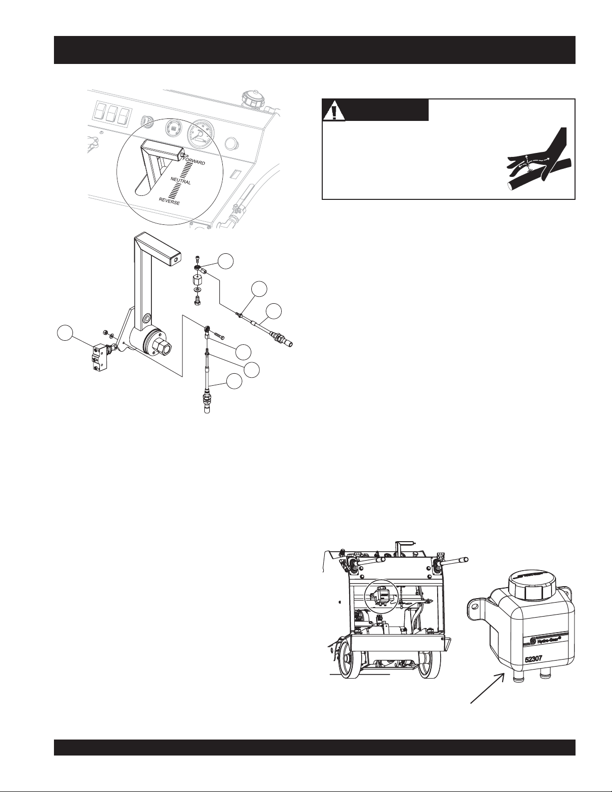
PS7060 MULTIQUIP SAW — MAINTENANCE
F-N-R Control Adjustment
4
Hydraulic System Maintenance
DANGERDANGER
DANGER
DANGERDANGER
NEVER use your hand to find hydraulic
leaks. Use a piece of wood or cardboard.
Hydraulic fluid injected into the skin must
be treated by a knowledgable physician
immediately or severe injury or death can
occur.
Many hydraulic problems are a result of low fluid levels. Before
checking any other possibilities, make sure the hydraulic fluid
level is correct.
2
1. Correct hydraulic fluid level.
1
3
2
2. Plugged hydraulic oil filter
3. Loose or leaking fittings.
4. Ruptured/damaged hydraulic lines.
5. Faulty hydraulic pump.
1
1. Adjustment Nut
2. Rod End
3. Push-Pull Cable
4. Neutral Safety Switch
Figure 65. F-N-R Control Adjustment
Control (Cable) adjustment for the F-N-R should not normally
be necessary, however, some adjustment can be made on each
of the Rod End adjustment nuts.
3
Hydraulic Oil System
1. Check hydraulic oil level daily.
2. When checking or adding hydraulic oil, place the machine
so the saw frame is level to get an accurate reading.
3. Hydraulic oil should be 1/2" to 1" in the Oil Reserve when
cold.
4. If hydraulic oil level is low add oil to 1/2" to 1".
5. Use 15W-40 premium grade engine oil.
6. Change oil and filter annually.
Figure 66. Oil Reserve Fill Line
PS7060 MULTIQUIP SAW • OPERATION MANUAL — REV. #2 (06/02/08) — PAGE 53
Page 54

PS7060 MULTIQUIP SAW — MAINTENANCE
1
5
1. Hydraulic Reservoir
2. Filter
3. Pump
4. Wheel Motor
5. Engine Pivot Cylinder
6. Engine Tilt Cylinder
7. Motor
8. Pump Body
3
8
4
6
1. Place an oil pan beneath the Blade Shaft Housing (1).
2. Remove the drain plug from the bottom of the Blade Shaft
Housing.
3. Collect and dispose the used oil (and filter) in accordance
with ordinances and regulations of your area.
4. Remove used oil filter.
5. After oil is drained, reinstall drain plug.
6. Pre-fill and install a new oil filter.
2
7
9
4
9. Lift Cylinder
Figure 67. Hydraulic System
1
2
3
Figure 68. Hydraulic System Drains
PAGE 54 — PS7060 MULTIQUIP SAW • OPERATION MANUAL — REV. #2 (06/02/08)
CAUTIONCAUTION
CAUTION
CAUTIONCAUTION
To prevent hydraulic pump damage, pre-fill the filter with
oil prior to installing it.
7. Add oil to the system reservoir.
8. The reservoir will need to be filled several times.
9. Run the engine for 5-10 minutes to cycle the oil throughout
the system.
10. Add oil as required.
11. Repeat process until oil level is stable after running engine.
Page 55

PS7060 MULTIQUIP SAW — MAINTENANCE
Tips When Draining and Filling the Hydraulic Oil System
1. It will take 3-4 quarts to fill the hydraulic system when new, and
somewhat less when changing the oil.
2. Remove the oil reservoir cap to speed oil draining.
3. When re-filling the system, raise the saw halfway up, then
lift the rear of the saw until the Blade Flanges touch the
ground. This will help to speed the filling process.
4. After filling the system, jack the saw up so the drive wheels
are off the ground. Start the saw and move the Control
Handle half way into FORWARD to purge air out of the
system.
If the Blade Shaft is drained completely, it will
require approximately 1 gallon to refill.
Long Term Storage
■
Remove the battery.
■
Drain fuel from fuel tank and fuel lines.
■
Clean exterior with a cloth soaked in clean oil.
■
Store unit covered with plastic sheet in moisture and dustfree location out of direct sunlight.
Never store the saw with fuel in the tank for any extended
period of time. Always clean up spilled fuel immediately.
Decommissioning Saw/Components
Decommissioning is a controlled process used to safely retire a
piece of equipment that is no longer serviceable. If the equipment
poses an
or damage or is no longer cost effective to maintain, (beyond lifecycle reliability) and is to be decommissioned,
dismantlement), the following procedure must take place:
CAUTIONCAUTION
CAUTION
CAUTIONCAUTION
unacceptable and unrepairable safety risk due to wear
(demolition and
1. Drain all fluids completely. These may include oil, gasoline,
hydraulic oil and antifreeze. Dispose of properly in accor-
Stay-Level Handles (SLH)
The Stay-Level Handlebar system is designed to require very
little maintenance. (See Figure 69. below)
NEVER try to lift the saw with the handlebars (a lift bale is provided
for lifting). DO NOT try to dislodge a stuck blade by prying or
using excessive force on the handlebars.
dance with local and governmental regulations. Never pour
on ground or dump down drains or
2. Remove battery and bring to appropriate facility for lead
reclamation. Use safety precautions when handling batteries that contain sulfuric acid, (See page 16).
3. The remainder can be brought to a salvage yard or metal
reclamation facility for further dismantling.
sewers.
Figure 69. Stay Level Handlebar System
PS7060 MULTIQUIP SAW • OPERATION MANUAL — REV. #2 (06/02/08) — PAGE 55
Page 56

PS7060 MULTIQUIP SAW — MAINTENANCE
)ENIGNE(GNITOOHSELBUORT.11ELBAT
MOTPMYSESUACELBISSOPNOITULOS
?nidehsupnottuBpotSycnegremE.nottuBpotS-Etuo
."NO"yekhtiwrewopon,tratstonlliW
iwsnoitingI
uF
?)ypme
?deggolcsenil/retlifleuF .senilleufroretlifleufecalpeR
.tneserpleufoN.tratstonlliW
nI.ecalperronaelC
dnaelbaliavasileuf",tratsottluciffiD
."lamronsinoisserpmoc
htaerbpacknatleuF .packnatleufecalperronaelC
?enilleufniriA.enilleufdeelB
?epytleufgnorW
?degrahcsidrodetcennocsidyrettaB
?evitcefedgniriw/hct
knat(knatleufnielbaliavatonle
?deggolcelohre
?evitcefedrodeggolcevlavnoitcej
)trid,retaW(?metsysleufdetanimatnoC.metsysleufhsulF
lluP
egrahc,snoitcennocelbackcehC
.yrettabecalperro
kcehC.hctiwsnoitingiecalpeR
.gniriw
.leuffoepyttcerrochtiwlliF
sysleufhsulF
.leuffoepyttcerrochtiw
ecalperdna,met
?ytridrenaelcriA.r
oitcuS.sevlavtaes-eR
dnaelbaliavasileuf",tratsottluciffiD
."wolsinoisserpmoc
aehrednilyCstlobdaehrednilyceuqroT
?degamadteksagdaeH.steksagdaehecalpeR
Certain operations referred to in this
troubleshooting section such as re-seating
valves or replacing piston rings may require
special tools and must be performed by trained
and competent personnel.
enaelcriaecalpeR
?dedurtorprokcutsevlavtsuahxe/n
?nrowrednilycro/dnagnirnotsiP
?ylreporpdenethgittond
.notsip
ro/dnasgnirnotsipecalpeR
For further engine troubleshooting, see your
engine owner's manual
PAGE 56 — PS7060 MULTIQUIP SAW • OPERATION MANUAL — REV. #2 (06/02/08)
Page 57

PS7060 MULTIQUIP SAW — TROUBLESHOOTING
)DEUNITNOC,ENIGNE(GNITOOHSELBUORT.21ELBAT
MOTPMYSESUACELBISSOPNOITULOS
?detcirtserriaekatnI
.yrassecen
eddnatridfoekatniriaraelC
.sirb
sastnemelerenaelcriaecalpeR
reporpsinoisserpmoc"rewopnikaeW"
.erifsimtonseoddna
?skaeleniLnoitcejnI.senilecalperroriapeR
gnikaelenilriaegrahC.enilecalperroriapeR
?
?metsysleufniretaW
reporpsinoisserpmoc"rewopnikaeW"
.serifsimtub
,egamaD.srotcejniecalperronaelC
.staehrevoenignE
?evitcefednoitingI.noitingiecalpeR
?epytleufgnorW
?detcirtserriaekatnI
fedevlaVnoitcejnI.evlavnoitcejnIecalpeR
?evitce
?leufdetanimatnocroleufreporpmI
.ytilauq
.leufepyttcerroc
?secifirorotcejnInrowro
tcerroc
.yrassecen
atnocfimetsysleufhsulF
.leuffoepyt
.detanim
debircserpfoleufnaelchtiwllifeR
htiwecalperdnametsysleufhsulF
htiwecalperdna,metsysleufhsulF
.sirbeddnatridfoekatniriaraelC
sastnemelerenaelcriaecalpeR
?ytridsnifgnilooC.snifgniloocnaelC
?hgihootrowolotlevelliO.levelre
?yltcerrocdetsujdaronrevoG.ronrevogtsujdA
.setautculfdeepslanoitatoR
mretratS
.noitcnufla
PS7060 MULTIQUIP SAW • OPERATION MANUAL — REV. #2 (06/02/08) — PAGE 57
ttaB .yrettabecalperroegrahceR
nirpsronrevoG.gnirpsronrevogecalpeR
?detcirtserwolfleuF
?gniriwdegamad,esooL
?degrahcyltneiciffusniyre
?gnissimroevitcefedg
.sgolc
?detrohsyllanretnirodegamadretratS.retratSecalpeR
porpotliotsujdA
roskaelrofmetsysleuferitnekcehC
nosnoitcennocnaelc,thgiterusnE
.retratsdnayrettab
Page 58

PS7060 MULTIQUIP SAW — TROUBLESHOOTING
GNITOOHSELBUORTEDALB.31ELBAT
MOTPMYS MELBORPELBISSOP NOITULOS
?tuc
?stleb-evirdnrowroesool
.gnittucspotsroswolsedalB
thgiartstuctonseodedalB
.eurtro/dna
?rewopenignetneiciffusnI .gnitoohselbuortenignEotrefeR.gnitteselttorhtkcehC
?wasnodengilasimedalB .ytirgetnitnemngilakcehC
?tucgnieblairetam
?segnalfdnasredluohs
gnieblairetamehtrofdrahootedalB
.edalbeht"sserdeR"
foesuacebdehsinimideuqrotenignE
?noitatorfonoitceridreporpmI
?tfahsedalbehtnognippilssiedalB
?elbbowedalbroevissecxe"paGtuC"
ehtrofdrahylevissecxesiedalB
?MPRreporpmitadesugniebedalB
robranodetnuomylreporpmiedalB
.tfahsedalbeht
.gnitaes
.ecalperrostlebnoisnet-eR
.noitcerid"gnittuC-nwoD"anistniopworra
.noitamrofnirofpiuqitluMrorelaeDtlusnoC.tuc
.000,01yletamixorppa
gnittucyrT.edalbtcerrocrofpiuqitluMrorelaeDtlusnoC
ot)kcolbrednic,kcirbacilis,enotsdnas(lairetamtfosyrev
lanoitatordnadetneiroylreporpsiedalbehttahtkcehC
nodellatsniylreporperanipegnalf&edalbehttahtkcehC
edalbdnaegamad,raewrofegnalfdnatfahsedalbkcehC
gnieblairetamehthtiwedalbehtfonoitacificepskcehC
si)MPFS(deepsetunimrepteefecafrusedalberusnE
.tfahsedalbehtnodexiffaylreporpsiedalberusnE
?gnittuc
?rehtoehtton
?tuc
?segnalfdnasredluohs
gnilkcarc,gnirolocsidedalB
.ylevissecxegniraewro/dna
?retaw
?dnuorfotuoelohrobrA .tfahsedalbehtnodexiffaylreporpsiedalberusnE
?tucgnieb
?gnittuc
elihwedalbotdeilppaecrofevissecxE
dnaedisenonotuogniraewedalB
gnieblairetamehtrofdrahootsedalB
robranodetnuomylreporpmiedalB
gniloochguonegniviecertonedalB
lairetamrofnesohcedalbtcerrocnI
elihwedalbotdeilppaecrofevissecxE
TONOD dnawolsaylppA.tucehtniedalbehtecrof
.gniwasnehwecapydaets
edalbdnaegamad,raewrofegnalfdnatfahsedalbkcehC
.gnitaes
gnittucyrT.edalbtcerrocrofpiuqitluMrorelaeDtlusnoC
ot)kcolbrednic,kcirbacilis,enotsdnas(lairetamtfosyrev
.edalbeht"sserdeR"
.tfahsedalbehtnodexiffaylreporpsiedalberusnE
tewrofdedivorpsiretawfoemulov&wolfreporperusnE
.sedalbgnittuc
gnieblairetamehthtiwedalbehtfonoitacificepskcehC
.noitamrofnirofpiuqitluMrorelaeDtlusnoC.tuc
otnidehsinrubroyawanrowlairetamevisarbadnomaiD
dnaegamadrotnemngilarofwaskcehC.latemeht
.edalbwasecalper
PAGE 58 — PS7060 MULTIQUIP SAW • OPERATION MANUAL — REV. #2 (06/02/08)
Page 59

NOTES
PS7060 MULTIQUIP SAW • OPERATION MANUAL — REV. #2 (06/02/08) — PAGE 59
Page 60

16
AWG
Red/White
16
AWG
Yellow/Blue
16
AWG
Dark
Green
16
AWG
Yellow/Orange
16
AWG
Yellow
16
AWG
Yellow/Black
16
AWG
Orange
16
AWG
Tan
16
AWG
Black
16
AWG
Black
10
AWG
Red
12
AWG
Red/Black
10
AWG
Tan
16
AWG
Black
10
AWG
Red
16
AWG
Black
16
AWG
Red
16
AWG
Red
16
AWG
Red/White
16
AWG
Black
16
AWG
Brown
16
AWG
White
16
AWG
Red/Black
16
AWG
Grey
16
AWG
Lite
Blue
16
AWG
Red
16
AWG
Orange
16
AWG
Red
12 AWG Red
12 AWG Red
10
AWG
Red
16
AWG
Red/Black
16
AWG
Black
16
AWG
Black
16
AWG
Black
16
AWG
Lite
Blue
16
AWG
Orange
16
AWG
Red
16
AWG
Lite
Blue
16
AWG
Black
10
AWG
Red
16
AWG
Black
16
AWG
Black
16
AWG
Orange
10
AWG
Red
16 AWG Red/Black
16
AWG
Red/Black
14
AWG
Purple
14
AWG
Purple
16
AWG
Red/White
14
AWG
Pink/Black
12
AWG
Red
16
AWG
Black
14
AWG
Pink/Black
16
AWG
Red
14
AWG
Pink/Black
16
AWG
Red/Black
16
AWG
Lite
Green/Black
16
AWG
Yellow/Black
16
AWG
Black
16
AWG
Black
16
AWG
Grey
+
-
PS7060 MULTIQUIP SAW — ELECTRICAL DIAGRAM TO SN AF3700155
ELECTRICAL DIAGRAM UP TO S/N AF3700155
16 AWG Red
16 AWG Black
14 AWG Pink/Black
16 AWG Black
14 AWG Pink/Black
16 AWG Black
16 AWG Tan
III
III
III
II
II
I
16 AWG Red/Black
14 AWG Purple
16 AWG Red/Black
16 AWG Red/Black
14 AWG Purple
III
12 AWG Red
12 AWG Red
16 AWG Yellow/Black
16 AWG Black
16 AWG Yellow
16 AWG Lite Green/Black
14 AWG Pink/Black
16 AWG Dark Green
16 AWG Yellow/Orange
16 AWG Yellow/Black
12 AWG Red
16 AWG Yellow/Blue
16 AWG Red
16 AWG Red
16 AWG Red/White
16 AWG Black
16 AWG Brown
16 AWG White
16 AWG Red/White
16 AWG Red/White
16 AWG Red
II
I
0
10 AWG Red
16 AWG Orange
16 AWG Red
16 AWG Lite Blue
16 AWG Grey
16 AWG Black
16 AWG Black
16 AWG Grey
16 AWG Lite Blue
16 AWG Red
16 AWG Orange
16 AWG Orange
10 AWG Red
16 AWG Lite Blue
16 AWG Black
16 AWG Black
16 AWG Orange
10 AWG Red
10 AWG Red
10 AWG Red
12 AWG Red/Black
10 AWG Tan
16 AWG Black
16 AWG Red/Black
16 AWG Red/Black
PAGE 60 — PS7060 MULTIQUIP SAW • OPERATION MANUAL — REV. #2 (06/02/08)
16 AWG Black
16 AWG Black
16 AWG Black
16 AWG Black
Page 61

.
.
.
.
.
.
.
. . .
.
.
I
II
III
0
I
III
III
III
II
II
MP1
J10
J28
J27
G1
CR4
MOT2
J33
V1
SP1
P3
J40
SP3
SP2
P5
SS1
SP4
J45
SP5
SS2
J43
J21
J14
J20
J3
J2
J4
RS1
P2
L1
PB1
J30
J15
V2
RS2
J44
P1
R1
J29
CR1
J16
CTL1
CR2
CR3
J17
J25
J39
J38
J34
J41
LS3
RS4
J9
J11
J12
J26
LS2
J18
RS3
J1
TG1
J36
J37
MOT1
J42
LS1
BAT1
KS1
J24
J19
J8
CB2
J13
J7
CB1
J6
J5
J31
CB4
J32
P4
J35
PJ1
J22
J23
J46
CB3
Magnetic
Pickup
Deutsch
DT
Tachometer
Lift
Lower
Valve
Deutsch
DT
Deutsch
DT
Spike
Supressor
Deutsch
DT
Spike
To
Water
Valve
PosLock
6.3mm
(1/4")
Water
Valve
Lights
E-Stop
#10
Ring
Glowplug
JPT-10
Deutz
2011F
Valve
Manifold
Lights
1/2W
Time
Delay
#10
Ring
Chassis
Console
MC6LC
Starter
Relay
Preheat
Relay
Delphi
GT
Depth
Stop
Blade
Shaft
Airflow
Restriction
Ground
Fault
Test
Solenoid
Starter
Starter
Motor
Ground
Neutral
Safety
Keyswitch
Power
Control
Engine
Lights
Deutsch
DT
Glowplug
Connector
Light
Engine
Block
1/2
Ring
Ground
Controls
A
B
30 50 15 31 R L TK H
30 85 86 87
1
2
3
4
5
6
-
+
21
A
B
B
A
21
21
21
A
B
21
1
TACHOMETER
2
D+
ALTERNATOR
3
TEMP
GAUGE
4
TEMP
SWITCH
5
PRESSURE
GAUGE
6
PRESSURE
SWITCH
7
SOLENOID
8
SOLENOID
GROUND
9
EXCESS
FUEL
10
EXCESS
FUEL
B
A
2 4 5 6 8
Out
30
IN2
IN1
31
IN2
Airflow
IN4
Preheat
GEN
PSI
Sw
IN1
D+
Alt
IN3
Aux
Sw
2
IN5
Temp
Sw
NC3
NC
KL.15
Accy
NC2
NC
KL.31
Ground
MAG
Solenoid
NC1
NC
C
B
A
1
2
3
4
5
6
1
2
3
4
5
6
+
-
31
30 50
+
-
15/54
15/54
50a
19
19
30
30
17
17
1
30
2
30
3
17
4
17
5
15/54
6
15/54
7
50A
8
19
9
19
10
58
1
2
3
4
.
.
.
.
.
.
.
.
.
.
.
.
.
.
.
.
.
.
.
.
.
.
.
.
.
.
.
.
.
.
.
.
.
.
.
.
.
.
.
.
.
.
.
.
.
.
.
.
.
2.2
k
.
.
.
.
.
.
.
.
.
.
16
AWG
Red/White
16
AWG
Yellow/Blue
16
AWG
Dark
Green
16
AWG
Yellow/Orange
16
AWG
Yellow
.
16
AWG
Yellow/Black
.
.
.
.
.
.
.
.
.
.
.
.
.
.
.
.
.
.
.
.
. . .
.
.
.
.
.
.
.
.
.
.
.
.
.
.
.
.
.
.
.
.
.
.
.
.
.
.
.
12V
.
.
.
.
.
.
.
.
.
.
.
10A
.
.
10A
.
.
.
.
50A
.
. . .
16
AWG
Red
16
AWG
Orange
16
AWG
Tan
16
AWG
Red
16
AWG
Black
16
AWG
Black
10
AWG
Red
12
AWG
Red/Black
10
AWG
Tan
16
AWG
Black
10
AWG
Red
16
AWG
Black
16
AWG
Red
16
AWG
Red
16
AWG
Red/White
16
AWG
Black
16
AWG
Brown
16
AWG
White
16
AWG
Red/Black
16
AWG
Grey
16
AWG
Lite
Blue
16
AWG
Red
16
AWG
Orange
16
AWG
Red
12 AWG Red
12 AWG Red
16 AWG Red
10
AWG
Red
16
AWG
Red/Black
16
AWG
Black
16
AWG
Black
16
AWG
Black
16
AWG
Lite
Blue
16
AWG
Orange
16
AWG
Red
16
AWG
Lite
Blue
16
AWG
Black
.
.
.
.
.
.
.
.
.
.
.
.
16
AWG
Black
10
AWG
Red
16
AWG
Black
16
AWG
Black
16
AWG
Orange
10
AWG
Red
16 AWG Red/Black
14 AWG Pink/Black
14
AWG
Pink/Black
16 AWG Black
16
AWG
Red/Black
14
AWG
Purple
14
AWG
Purple
16
AWG
Red/Black
10A
12
AWG
Red
16
AWG
Red/White
14
AWG
Pink/Black
16
AWG
Lite
Green/Black
16
AWG
Yellow/Black
16
AWG
Black
16
AWG
Black
16
AWG
Grey
Pump
Supressor
110
115
117
120
103
106
107
160
156
105
104
101
102
119
118
121
123
163
152
116
138
151
155
161
162
128
134
109
140
112
108
131
136
137
142
146
150
153
149
154
122
125
126
133
144
147
111
129
159
132
113
157
158
135
145
143
141
114
124
130
127
148
139
PS7060 MULTIQUIP SAW — ELECTRICAL DIAGRAM SN AF3700156 & UP
ELECTRICAL DIAGRAM S/N AF3700156 AND UP
Magnetic
Lights
Deutz 2011F
TEMP GAUGE
TACHOMETER
Light
Deutsch DT
Connector
Deutsch DT
TEMP SWITCH
D+ ALTERNATOR
PRESSURE GAUGE
PRESSURE SWITCH
SOLENOID GROUND
EXCESS FUEL
EXCESS FUEL
16 AWG Red/Black
Airflow Restriction
Control
16 AWG Black
To Water Valve
16 AWG Red
16 AWG Red
6.3mm (1/4")
Water Valve
16 AWG Red
16 AWG Red/White
16 AWG Black
PS7060 MULTIQUIP SAW • OPERATION MANUAL — REV. #2 (06/02/08) — PAGE 61
16 AWG Red/White
16 AWG Brown
16 AWG White
16 AWG Red/White
Lights
16 AWG Yellow/Blue
16 AWG Yellow/Black
14 AWG Pink/Black
12 AWG Red
16 AWG Dark Green
PSI Sw
16 AWG Lite Green/Black
16 AWG Yellow/Orange
D+ Alt
Ground
Aux Sw 2
Tachometer
Ground Fault Test
16 AWG Yellow
16 AWG Yellow/Black
Temp Sw
Console
14 AWG Purple
#10 Ring
14 AWG Purple
J21
16 AWG Red/Black
16 AWG Red/Black
J23
J22
Starter Relay
Time Delay
Preheat Relay
12 AWG Red
16 AWG Red/Black
12 AWG Red
Keyswitch
16 AWG Black
16 AWG Black
16 AWG Red
14 AWG Pink/Black
16 AWG Red
Glowplug
16 AWG Red/Black
10 AWG Tan
2.2 k
16 AWG Tan
#10 Ring
16 AWG Black
16 AWG Black
16 AWG Black
14 AWG Pink/Black
12 AWG Red/Black
Engine Block
Ground
J46
J37
Solenoid
1/2 Ring
10 AWG Red
10 AWG Red
10 AWG Red
Lower Valve
16 AWG Black
16 AWG Black
16 AWG Black
Deutsch DT
Deutsch DT
16 AWG Black
16 AWG Orange
16 AWG Black
16 AWG Lite Blue
Glowplug
10 AWG Red
16 AWG Orange
16 AWG Grey
16 AWG Black
Deutsch DT
16 AWG Black
16 AWG Black
16 AWG Grey
Blade Shaft
16 AWG Red
Depth Stop
16 AWG Lite Blue
16 AWG Red
16 AWG Orange
Delphi GT
16 AWG Orange
16 AWG Red
16 AWG Lite Blue
153
10 AWG Red
Page 62

PS7060 MULTIQUIP SAW — HYDRAULIC SCHEMATIC TO SN AF3700155
HYDRAULIC SCHEMATIC TO SN AF3700155
1. Lift Cylinder Assembly
2. Lift Pump
3. Reservoir
4. Blade Shaft Assembly
5. Brake Cylinder
6. Spin-On Filter
7. Hydrostatic Pump
8. Engine Pivot Cylinder 2.5"
9. Valve Assembly
PAGE 62 — PS7060 MULTIQUIP SAW • OPERATION MANUAL — REV. #2 (06/02/08)
10. Wheel Motor
11. Velocity Fuse
12. Check Valve (2)
13. Valve 4W2P
14. Lift Cylinder
15. Pilot Piston
16. O-Ring
17. Backup (2)
Page 63

PS7060 MULTIQUIP SAW — HYDRAULIC SCHEMATIC SN AF3700156 & UP
HYDRAULIC SCHEMATIC SN AF3700156 AND UP
1. Lift Cylinder Assembly
2. Lift Pump
3. Reservoir
4. Blade Shaft Assembly
5. Brake Cylinder
6. Spin-On Filter
7. Hydrostatic Pump
8. Cylinder and Valve Assembly
9. Wheel Motor
PS7060 MULTIQUIP SAW • OPERATION MANUAL — REV. #2 (06/02/08) — PAGE 63
10. Check Valve (2)
11. Velocity Fuse
12. Engine Pivot Cylinder 2.5"
13. Valve 4W2P
14. Lift Cylinder
15. Pilot Piston
16. O-Ring
17. Backup (2)
Page 64

TERMS AND CONDITIONS OF SALE — PARTS
PAYMENT TERMS
Terms of payment for parts are net 30 days.
FREIGHT POLICY
All parts orders will be shipped collect or
prepaid with the charges added to the invoice.
All shipments are F.O.B. point of origin.
Multiquip’s responsibility ceases when a signed
manifest has been obtained from the carrier,
and any claim for shortage or damage must be
settled between the consignee and the carrier.
MINIMUM ORDER
The minimum charge for orders from Multiquip
is $15.00 net. Customers will be asked for
instructions regarding handling of orders not
meeting this requirement.
RETURNED GOODS POLICY
Return shipments will be accepted and credit
will be allowed, subject to the following provisions:
1. A Returned Material Authorization must
be approved by Multiquip prior to shipment.
2. To obtain a Return Material Authorization,
a list must be provided to Multiquip Parts
Sales that defines item numbers, quantities, and descriptions of the items to be
returned.
a. The parts numbers and descriptions
must match the current parts price
list.
b. The list must be typed or computer
generated.
c. The list must state the reason(s) for
the return.
d. The list must reference the sales
order(s) or invoice(s) under which the
items were originally purchased.
e. The list must include the name and
phone number of the person requesting the RMA.
3. A copy of the Return Material Authorization must accompany the return shipment.
4. Freight is at the sender’s expense. All
parts must be returned freight prepaid to
Multiquip’s designated receiving point.
5. Parts must be in new and resalable con-
6. The following items are not returnable:
7. The sender will be notified of any material
8. Such material will be held for five working
9. Credit on returned parts will be issued at
10. In cases where an item is accepted, for
11. Credit issued will be applied to future
PRICING AND REBATES
Prices are subject to change without prior
notice. Price changes are effective on a specific date and all orders received on or after that
date will be billed at the revised price. Rebates
for price declines and added charges for price
increases will not be made for stock on hand
at the time of any price change.
Multiquip reserves the right to quote and sell
dition, in the original Multiquip package (if
any), and with Multiquip part numbers
clearly marked.
a. Obsolete parts. (If an item is in the
price book and shows as being replaced by another item, it is obsolete.)
b. Any parts with a limited shelf life
(such as gaskets, seals, “O” rings,
and other rubber parts) that were purchased more than six months prior to
the return date.
c. Any line item with an extended dealer
net price of less than $5.00.
d. Special order items.
e. Electrical components.
f. Paint, chemicals, and lubricants.
g. Decals and paper products.
h. Items purchased in kits.
received that is not acceptable.
days from notification, pending instructions. If a reply is not received within five
days, the material will be returned to the
sender at his expense.
dealer net price at time of the original
purchase, less a 15% restocking charge.
which the original purchase document
can not be determined, the price will be
based on the list price that was effective
twelve months prior to the RMA date.
purchases only.
direct to Government agencies, and to Original
Equipment Manufacturer accounts who use
our products as integral parts of their own
products.
SPECIAL EXPEDITING SERVICE
A $35.00 surcharge will be added to the invoice
for special handling including bus shipments,
insured parcel post or in cases where Multiquip
must personally deliver the parts to the carrier.
LIMITATIONS OF SELLER’S LIABILITY
Multiquip shall not be liable hereunder for
damages in excess of the purchase price of the
item with respect to which damages are
claimed, and in no event shall Multiquip be
liable for loss of profit or good will or for any
other special, consequential or incidental dam-
ages.
LIMITATION OF WARRANTIES
No warranties, express or implied, are made
in connection with the sale of parts or trade
accessories nor as to any engine not manufac-
tured by Multiquip. Such warranties made in
connection with the sale of new, complete units
are made exclusively by a statement of war-
ranty packaged with such units, and Multiquip
neither assumes nor authorizes any person to
assume for it any other obligation or liability
whatever in connection with the sale of its
products. Apart from such written statement of
warranty, there are no warranties, express,
implied or statutory, which extend beyond the
description of the products on the face hereof.
Effective: February 22, 2006
PAGE 64 — PS7060 MULTIQUIP SAW • OPERATION MANUAL — REV. #2 (06/02/08)
Page 65

NOTES
PS7060 MULTIQUIP SAW • OPERATION MANUAL — REV. #2 (06/02/08) — PAGE 65
Page 66

OPERATION MANUAL
HERE’S HOW TO GET HELP
PLEASE HAVE THE MODEL AND SERIAL
NUMBER
UNITED STATES
Multiquip Corporate Office MQ Parts Department
18910 Wilmington Ave. Tel. (800) 421-1244 800-427-1244 Fax: 800-672-7877
Carson, CA 90746 Fax (800) 537-3927 310-537-3700 Fax: 310-637-3284
Contact: mq@multiquip.com
Mayco Parts Warranty Department
800-306-2926 Fax: 800-672-7877 800-421-1244, Ext. 279 Fax: 310-537-1173
310-537-3700 Fax: 310-637-3284 310-537-3700, Ext. 279
Service Department Technical Assistance
800-421-1244 Fax: 310-537-4259 800-478-1244 Fax: 310-631-5032
310-537-3700
MEXICO UNITED KINGDOM
MQ Cipsa Multiquip (UK) Limited Head Office
Carr. Fed. Mexico-Puebla KM 126.5 Tel: (52) 222-225-9900 Hanover Mill, Fitzroy Street, Tel: 0161 339 2223
Momoxpan, Cholula, Puebla 72760 Mexico Fax: (52) 222-285-0420 Ashton-under-Lyne, Fax: 0161 339 3226
Contact: pmastretta@cipsa.com.mx Lancashire OL7 0TL
CANADA BRAZIL
Multiquip Multiquip
4110 Industriel Boul. Tel: (450) 625-2244 Av. Evandro Lins e Silva, 840 - grupo 505 Tel: 011-55-21-3433-9055
Laval, Quebec, Canada H7L 6V3 Fax: (450) 625-8664 Barra de Tijuca - Rio de Janeiro Fax: 011-55-21-3433-9055
Contact: jmartin@multiquip.com Contact: cnavarro@multiquip.com.br, srentes@multiquip.com.br
ON-HAND
WHEN CALLING
Contact: sales@multiquip.co.uk
© COPYRIGHT 2008, MULTIQUIP INC.
Multiquip Inc and the MQ logo are registered trademarks of Multiquip Inc. and may not be used, reproduced, or altered without written permission. All other trademarks
are the property of their respective owners and used with permission.
This manual MUST accompany the equipment at all times. This manual is considered a permanent part of the equipment and should remain with the unit if resold.
The information and specifications included in this publication were in effect at the time of approval for printing. Illustrations, descriptions, references and technical
data contained in this manual are for guidance only and may not be considered as binding. Multiquip Inc. reserves the right to discontinue or change specifications,
design or the information published in this publication at any time without notice and without incurring any obligations.
Your Local Dealer is:
 Loading...