

Page 1

OPERATION AND PARTS MANUAL
MODEL PRO46
WALK-BEHIND TROWEL
(HONDA GX340UT2QA2/GX340UT2QAP2
GASOLINE ENGINES)
Revision #1 (8/20/15)
Original Version
To find the latest revision of this
publication, visit our website at:
www.multiquip.com
THIS MANUAL MUST ACCOMPANY THE EQUIPMENT AT ALL TIMES.
PN: 30327
Page 2

FUEL AND CHEMICAL EXPOSURE WARNINGS
Gasoline engine exhaust and some of
its constituents, and some dust created
by power sanding, sawing, grinding,
drillingandotherconstructionactivities
contains chemicals known to the State
of California to cause cancer, birth
defects and other reproductive harm.
Some examples of these chemicals are:
Leadfromlead-basedpaints.
Crystallinesilicafrombricks.
Cementandothermasonryproducts.
Arsenicandchromiumfromchemically
treatedlumber.
Your risk from these exposures varies,
dependingonhowoftenyoudo this type
of work. To reduce your exposure to
these chemicals: work in aALWAYS
well ventilated area, and work with
approved safety equipment, suchas
dust masks that are specially designed
to filter out microscopic particles.
PAGE 2 — PRO46 SERIES WALK-BEHIND TROWEL • OPERATION AND PARTS MANUAL — REV. #1 (8/20/15)
Page 3

SILICOSIS/RESPIRATORY WARNINGS
WARNING
SILICOSIS WARNING RESPIRATORY HAZARDS
Grinding/cutting/drilling of masonry, concrete, metal and
other materials with silica in their composition may give
off dust or mists containing crystalline silica. Silica is a
basic component of sand, quartz, brick clay, granite and
numerous other minerals and rocks. Repeated and/or
substantial inhalation of airborne crystalline silica can
cause serious or fatal respiratory diseases, including
silicosis.In addition, California and some other
authorities have listed respirable crystalline silica as a
substance known to cause cancer. When cutting such
materials, always follow the respiratory precautions
mentioned above.
WARNING
Grinding/cutting/drilling of masonry, concrete, metal and
other materials can generate dust, mists and fumes
containing chemicals known to cause serious or fatal
injury or illness, such as respiratory disease, cancer,
birth defects or other reproductive harm. If you are
unfamiliar with the risks associated with the particular
process and/or material being cut or the composition of
the tool being used, review the material safety data
sheet and/or consult your employer, the material
manufacturer/supplier, governmental agencies such as
OSHA and NIOSH and other sources on hazardous
materials. California and some other authorities, for
instance, have published lists of substances known to
cause cancer, reproductive toxicity,or other harmful
effects.
Control dust, mist and fumes at the source where
possible. In this regard use good work practices and
follow the recommendations of the manufacturers or
suppliers, OSHA/NIOSH, and occupational and trade
associations.Water should be used for dust
suppression when wet cutting is feasible. When the
hazards from inhalation of dust, mists and fumes cannot
be eliminated, the operator and any bystanders should
always wear a respirator approved by NIOSH/MSHA for
the materials being used.
PRO46 SERIES WALK-BEHIND TROWEL • OPERATION AND PARTS MANUAL — REV. #1 (8/20/15) — PAGE 3
Page 4

TABLE OF CONTENTS
PRO46
WALK-BEHIND TROWEL
Fuel And Chemical Exposure Warnings .................. 2
Silicosis/Respiratory Warnings ................................ 3
Table Of Contents .................................................... 4
Training Checklist .................................................... 5
Daily Pre-Operation Checklist ................................. 6
Safety Information .............................................. 7-11
Trowel Specifications/Dimensions ......................... 12
Engine Specifications ............................................ 13
General Information .......................................... 14-15
Trowel Components .......................................... 16-17
Engine Components .............................................. 18
Assembly And Installation ................................ 19-28
Inspection ......................................................... 29-30
Operation .......................................................... 30-36
Options ............................................................. 37-38
Maintenance ..................................................... 39-47
Troubleshooting ................................................ 48-51
Wiring Diagram ...................................................... 52
Explanation Of Code In Remarks Column............. 54
Suggested Spare Parts ......................................... 55
Honda GX340UT2QA2/GX340UTQAP2
Gasoline Engines
Recoil Starter Assembly ......................................82-83
Fan Cover Assembly......................................... 84-85
Carburetor Assembly ........................................ 86-87
Air Cleaner Assembly ....................................... 88-89
Muffler Assembly .............................................. 90-91
Fuel Tank Assembly .......................................... 92-93
Flywheel Assembly ........................................... 94-95
Cylinder Head Assembly .................................. 96-97
Ignition Coil Assembly ...................................... 98-99
Control Assembly ......................................... 100-101
Cylinder Barrel Assembly .......................................102-103
Crankcase Cover Assembly ..................................... 104-105
Crankshaft Assembly ................................................ 106-107
Piston Assembly ........................................... 108-109
Camshaft Assembly ...................................... 110-111
Labels Assembly .......................................... 112-113
Terms And Conditions Of Sale — Parts .............. 114
Component Drawings
Nameplates And Decals ................................... 56-57
Standard Handle Assembly .............................. 58-59
Standard Handle Assembly (Continued) .......... 60-63
Fresno Winch Assembly ................................... 64-65
Guard Ring And Engine Mounting Assembly. ... 66-67
Fresno Boom Assembly. ................................... 68-69
Brush To Fresno Kit 48" .................................... 70-71
Stabilizer Ring Assembly .................................. 72-73
Gearbox Assembly ...........................................74-75
Engine And Clutch Assembly ........................... 76-77
Spider Assembly ............................................... 78-79
Blades And Pan Assembly ...............................80-81
PAGE 4 — PRO46 SERIES WALK-BEHIND TROWEL • OPERATION AND PARTS MANUAL — REV. #1 (8/20/15)
Page 5

TRAINING CHECKLIST
Training Checklist
No. Description OK? Date
1
2
3 Fuel system, refueling procedure.
4
5
6 Emergency stop procedures.
7 Startup of machine, engine choke.
8 Maintaining a hover.
9 Maneuvering.
10 Pitching.
11 Concrete fi nishing techniques.
12 Shutdown of machine.
Read operation manual
completely.
Machine layout, location of
components, checking of engine
oil level.
Operation of controls (machine
not running).
Safety controls, safety stop switch
operation.
13 Lifting of machine (lifting bale).
14 Machine transport and storage.
PRO46 SERIES WALK-BEHIND TROWEL • OPERATION AND PARTS MANUAL — REV. #1 (8/20/15) — PAGE 5
Page 6

DAILY PRE-OPERATION CHECKLIST
Daily Pre-Operation Checklist
1 Engine oil level
2 Gearbox oil level
3 Condition of blades
4 Blade pitch operation
5 Safety stop switch operation
PAGE 6 — PRO46 SERIES WALK-BEHIND TROWEL • OPERATION AND PARTS MANUAL — REV. #1 (8/20/15)
Page 7

SAFETY INFORMATION
Do not operate or service the equipment before reading
the entire manual. Safety precautions should be followed
at all times when operating this equipment.
Failure to read and understand the safety
messages and operating instructions could
result in injury to yourself and others.
SAFETY MESSAGES
The four safety messages shown below will inform you
about potential hazards that could injure you or others. The
safety messages specifically address the level of exposure
to the operator and are preceded by one of four words:
DANGER, WARNING, CAUTION
SAFETY SYMBOLS
Potential hazard associated with the operation of this
which
may appear throughout this manual in conjunction with
associated with the operation of this
equipment will be referenced with hazard symbols
safety messages.
or NOTICE.
DANGER
Indicates a hazardous situation which, if not avoided,
WILL result in DEATH or SERIOUS INJURY.
WARNING
Indicates a hazardous situation which, if not avoided,
COULD result in DEATH or SERIOUS INJURY.
CAUTION
Indicates a hazardous situation which, if not avoided,
COULD result in MINOR or MODERATE INJURY.
NOTICE
Addresses practices not related to personal injury.
SYMBOL
Inhaling exhaust fumes can result in severe
injury or death.
Only operate equipment in well ventilated areas.
Gasoline fuel can cause fire or explosion. Stop
engine before refueling.
Keep cigarettes, sparks and flames away from hot
surfaces.
HOT PARTS can burn skin.
DO NOT
amount of time to cool before performing maintenance.
SAFETY HAZARD
WARNING
Lethal Exhaust Gas Hazard
inhale exhaust gases/fumes.DO NOT
WARNING
Explosive Fuel Hazard
CAUTION
Burn Hazard
touch hot parts. Allow machine a sufficient
Warning decals
equipment are defined below:
DECAL
ALWAYS
P/N 23700
On Quick Pitch™ models make sure T-Handle
latch is locked (engaged).
ALWAYS wear protective clothing when
P/N360
99
operating this equipment
This machine to be operated by qualified
personnel. Ask for training as needed.
SAFETY HAZARD
WARNING
Rotating Blade Hazard
Keep hands and feet clear of guard rings.
Stop engine before servicing.
WARNING
To avoid injury you must read and
understand operator’s manual before
using this machine.
NEVER
to stand underneath the trowel while lifting.
Read Manual
WARNING
Lifting Crush Hazard
allow any person
lift trowel with pans attached.DO NOT
make sure handle is securely attached.
WARNING
Training
PRO46 SERIES WALK-BEHIND TROWEL • OPERATION AND PARTS MANUAL — REV. #1 (8/20/15) — PAGE 7
WARNING
Guard Hazard
NEVER operate this equipment with guards
removed. Keep hands clear.
Page 8
GENERAL SAFETY
NOTICE
This equipment should only be operated by trained and
Whenever necessary, replace nameplate, operation and
Manufacturer does not assume responsibility for any
accident due to equipment modifications. Unauthorized
use accessories or attachments that are not
recommended by Multiquip for this equipment. Damage
keep
Also, know the phone numbers
fire department.
This information will be invaluable in the case of an
SAFETY INFORMATION
CAUTION
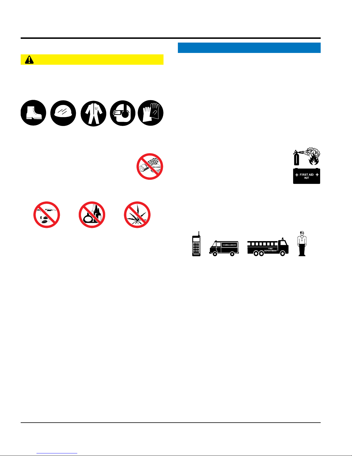
NEVER operate this equipment without proper protective
clothing, shatterproof glasses, respiratory protection,
hearing protection, steel-toed boots and other protective
devices required by the job or city and state regulations.
Avoid wearing jewelry or loose fitting clothes that may
snag on the controls or moving parts as this can cause
serious injury.
NEVER operate this equipment when not
feeling well due to fatigue, illness or when
under medication.
NEVER operate this equipment under the
influence of drugs or alcohol.
ALWAYS clear the work area of any debris, tools, etc.
that would constitute a hazard while the equipment is
in operation.
No one other than the operator is to be in the working
area when the equipment is in operation.
qualified personnel 18 years of age and older.
safety decals when they become difficult read.
equipment modification will void all warranties.
NEVER
to the equipment and/or injury to user may result.
ALWAYS know the location of the nearest
fire extinguisher.
ALWAYS know the location of the nearest
first aid kit.
ALWAYS know the location of the nearest phone or
a phone on the job site.
of the nearest ambulance, doctor and
emergency.
DO NOT use the equipment for any purpose other than
its intended purposes or applications.
PAGE 8 — PRO46 SERIES WALK-BEHIND TROWEL • OPERATION AND PARTS MANUAL — REV. #1 (8/20/15)
Page 9

SAFETY INFORMATION
TROWEL SAFETY
ALWAYS keep work area
Fix damage to machine and replace any broken parts
store equipment properly when it is not being
used. Equipment should be stored in a clean, dry location
out of the reach of children and unauthorized personnel.
A safety manual for operating and maintenance
personnel of concrete power trowels produced by the
Association of Equipment Manufacturers (AEM) can be
obtained for a fee by ordering through their website at
place hands or fingers inside engine
operate the engine with heat shields or
while the engine is hot. Allow the oil to cool before
performing maintenance. This will prevent scalding of
DANGER
Engine fuel exhaust gases contain poisonous carbon
monoxide. This gas is colorless and odorless, and can
cause death if inhaled.
The engine of this equipment requires an adequate free
flow of cooling air. NEVER operate this equipment in any
enclosed or narrow area
where free flow of the air is
restricted. If the air flow is
restricted it will cause injury
to people and property and
serious damage to the
equipment or engine.
NEVER operate the equipment in an explosive
atmosphere or near combustible materials. An
explosion or fire could result causing severe
bodily harm or even death.
WARNING
ALWAYS keep clear of rotating or moving
parts while operating the trowel.
DO NOT start or operate the trowel if the
drive train will not disengage. Centrifugal
force between the trowel and surface when starting can
cause uncontrolled handle movement that can cause
serious injury. The handle must not move while pulling
the engine recoil starter.
NEVER disconnect any emergency or safety devices.
These devices are intended for operator safety.
Disconnection of these devices can cause severe injury,
bodily harm or even death. Disconnection of any of these
devices will void all warranties.
CAUTION
clear around the trowel.
Make sure it is free of
debris and objects.
NOTICE
ALWAYS keep the machine in proper running condition.
immediately.
DANGEROUS
GAS FUMES
ALWAYS
www.aem.org.
Order FORM PT-160
ENGINE SAFETY
WARNING
DO NOT
compartment when engine is running.
NEVER
guards removed.
Keep fingers, hands hair and clothing away
from all moving parts to prevent injury.
DO NOT remove the engine oil drain plug
C
L
P
E
E
A
E
K
R
NEVER stand on trowel during operation.
NEVER lubricate components or attempt service on a
running machine.
NEVER place your feet or hands inside the guard rings
while starting or operating this equipment.
PRO46 SERIES WALK-BEHIND TROWEL • OPERATION AND PARTS MANUAL — REV. #1 (8/20/15) — PAGE 9
personnel.
CAUTION
NEVER touch the hot exhaust manifold,
muffler or cylinder. Allow these parts to cool
before servicing equipment.
Page 10
NOTICE
FUEL SAFETY
Store fuel in appropriate containers, in well-ventilated
Some walk-behind trowels can be lifted or moved by two
people utilizing lifting tubes or other special attachments.
Generally, however, they must be lifted using lifting bales
transport trowel with float pans attached unless
safety catches are used and are specifically cleared for
hoist the trowel more than three feet off the
Before lifting, make sure that the lifting bales are not
Always make sure crane or lifting device has been
Tighten fuel tank cap securely and close fuel cock to
Use adequate lifting cable (wire or rope) of sufficient
tie down equipment during transport by
NEVER run engine without an air filter or with a dirty air
filter. Severe engine damage may occur. Service air filter
frequently to prevent engine malfunction.
NEVER tamper with the factory settings
of the engine or engine governor. Damage
to the engine or equipment can result
if operating in speed ranges above the
maximum allowable.
SAFETY INFORMATION
areas and away from sparks and flames.
NEVER use fuel as a cleaning agent.
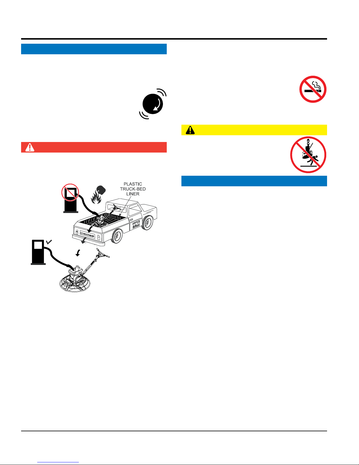
DO NOT smoke around or near the
equipment. Fire or explosion could result
from fuel vapors or if fuel is spilled on a
hot engine.
TRANSPORTING SAFETY
CAUTION
DANGER
DO NOT add fuel to equipment if it is placed inside
truck bed with plastic liner. Possibility exists of explosion
or fire due to static electricity.
FUEL
DO NOT start the engine near spilled fuel or combustible
fluids. Fuel is extremely flammable and its vapors can
cause an explosion if ignited.
ALWAYS refuel in a well-ventilated area, away from
sparks and open flames.
ALWAYS use extreme caution when working with
flammable liquids.
DO NOT fill the fuel tank while the engine is running
or hot.
DO NOT overfill tank, since spilled fuel could ignite if it
comes into contact with hot engine parts or sparks from
the ignition system.
FUEL
NEVER allow any person or animal to
stand underneath the equipment while
lifting.
NOTICE
and cranes, hoists, or forklifts.
NEVER
such transport by the manufacturer.
NEVER
ground with float pans attached.
damaged.
properly secured to the lifting bales of the equipment.
ALWAYS shutdown engine before transporting.
NEVER lift the equipment while the engine is running.
prevent fuel from spilling.
strength.
DO NOT lift machine to unnecessary heights.
ALWAYS
securing the equipment with rope.
PAGE 10 — PRO46 SERIES WALK-BEHIND TROWEL • OPERATION AND PARTS MANUAL — REV. #1 (8/20/15)
Page 11

SAFETY INFORMATION
ENVIRONMENTAL SAFETY/DECOMMISSIONING
Decommissioning is a controlled process used to safely
retire a piece of equipment that is no longer serviceable.
If the equipment poses an unacceptable and unrepairable
safety risk due to wear or damage or is no longer cost
effective to maintain (beyond life-cycle reliability) and is to
be decommissioned (demolition and dismantlement),be
sure to follow rules below.
EMISSIONS INFORMATION
The gasoline engine used in this equipment has been
designed to reduce harmful levels of carbon monoxide
(CO), hydrocarbons (HC) and nitrogen oxides (NOx)
This engine has been certified to meet US EPA Evaporative
Attempting to modify or make adjustments to the engine
emmission system by unauthorized personnel without
proper training could damage the equipment or create an
Additionally, modifying the fuel system may adversely affect
evaporative emissions, resulting in fines or other penalties.
The emission control label is an integral part of the emission
If a replacement emission label is needed, please contact
NOTICE
DO NOT pour waste or oil directly onto the ground, down
a drain or into any water source.
Contact your country's Department of
Public Works or recycling agency in your
area and arrange for proper disposal of
any electrical components, waste or oil
associated with this equipment.
When the life cycle of this equipment is over, remove
battery and bring to appropriate facility for lead
reclamation. Use safety precautions when handling
batteries that contain sulfuric acid.
When the life cycle of this equipment is over, it is
recommended that the trowel frame and all other metal
parts be sent to a recycling center.
Metal recycling involves the collection of metal from
discarded products and its transformation into raw
materials to use in manufacturing a new product.
Recyclers and manufacturers alike promote the process
of recycling metal. Using a metal recycling center
promotes energy cost savings.
NOTICE
contained in gasoline exhaust emissions.
emissions requirements in the installed configuration.
unsafe condition.
Emission Control Label
system and is strictly controlled by regulation(s).
The label must remain with the engine for its entire life.
your authorized engine distributor.
PRO46 SERIES WALK-BEHIND TROWEL • OPERATION AND PARTS MANUAL — REV. #1 (8/20/15) — PAGE 11
Page 12
TROWEL SPECIFICATIONS/DIMENSIONS
C
D
B
A
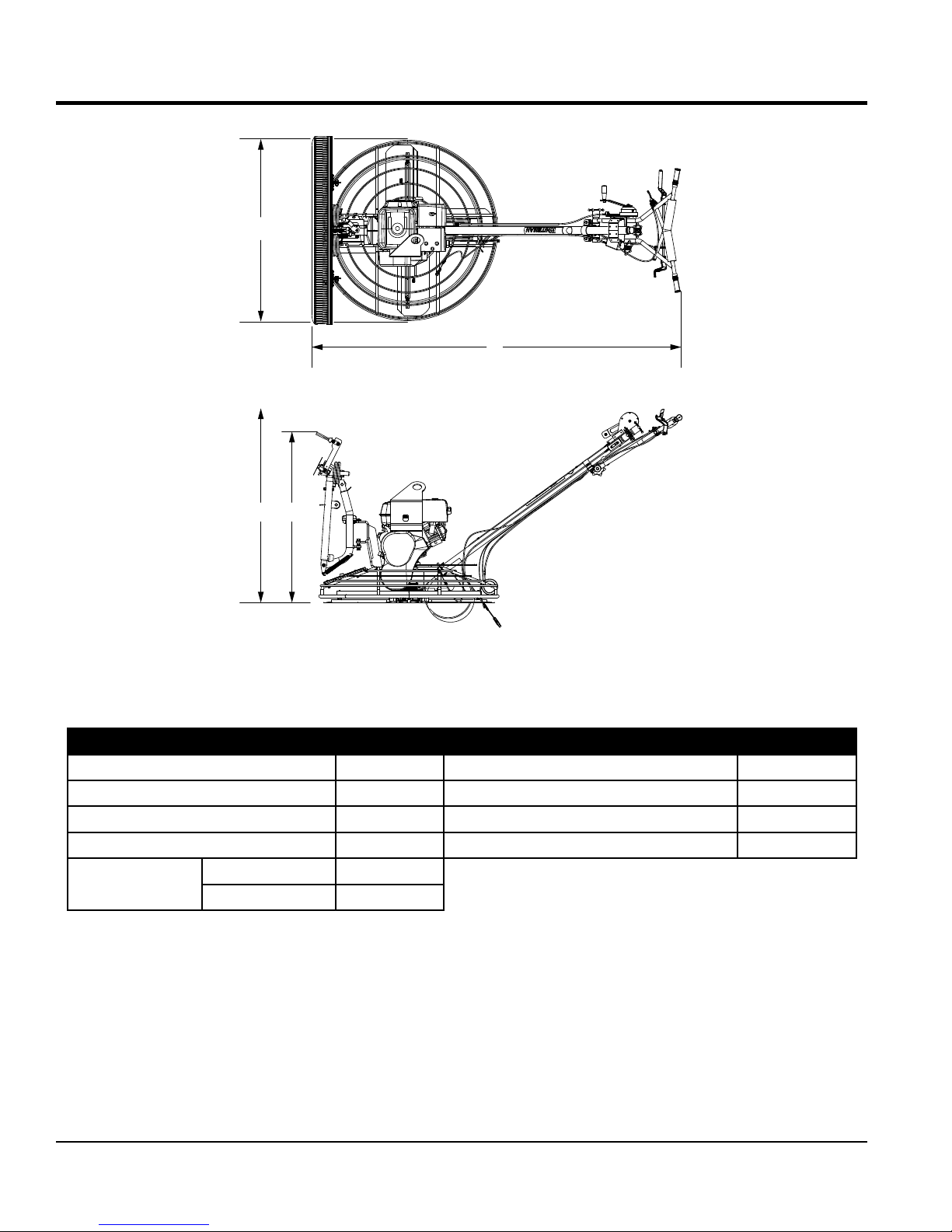
Figure 1. Dimensions
Table 1. Trowel Specifications
A–Height (Lifting Bale) –in (mm.) 34.5 (876.2) Path Width – in (mm.) 46 (1,168)
B–Height (Handle) – in (mm.) Standard 41.1 (1,044.2) Rotor – RPM (Dry Concrete) 60-130
C–Width (Ring Diameter) – in (mm.) 46.0 (1,168.4) Gear Box Oil Capacity – oz. (ml.)
26 (769)
D–Length – in (mm.) 75.2 (1,910.1) Shipping Weight – lbs (kg.) 350 (158.7)
Rotor 4
Number of Blades
Fresno 1
PAGE 12 — PRO46 SERIES WALK-BEHIND TROWEL • OPERATION AND PARTS MANUAL — REV. #1 (8/20/15)
Page 13

ENGINE SPECIFICATIONS
Table 2. PRO46 Noise and Vibration Emissions
Guaranteed ISO 11201:2010 Based
Sound Pressure Level at Operator Station in dB(A)
Guaranteed ISO 3744:2010 Based
Sound Power Level in dB(A)
Whole Body Vibration Per ISO 26311:1997+A1:2010 in m/s
NOTES:
1. Sound Pressure and Power Levels are “A” weighted Measures per ISO 226:2003 (ANSI S1.4-1981). They are measured with the operating
condition of the machine which generates the most repeatable but highest values of the sound levels. Under normal circumstances, the sound
level will vary depending on the condition of the material being worked upon.
2. The vibration level indicated is the vector sum of the RMS (Root Mean Square) Values of amplitudes on each axis, standardized to an 8 hour
exposure period, and obtained using operating condition of the machine that generates the most repeatable but highest values in accordance
with the applicable standards for the machine.
3. Per EU Directive 2002/44/EC, the daily exposure action value for whole body vibration is 0.5 m/s2 SA(8). The daily exposure limit value is
1.15 m/s2 SA(8).
2
SA(8)
96
121
Standard Handle
Position
Up 2.22
Down 1.61
Table 3. Engine Specifications/Dimensions
Model Honda GX340UT2QA2/GX340UT2QAP2
Type
Bore X Stroke 3.2 in. X 2.5 in. (82 mm x 64 mm)
Displacement 20.6 cu-in. (337 cc)
Max. Output 11 H.P. @ 3600 RPM
Fuel Tank Capacity Approx. 1.72 U.S. Gallons (6.5 Liters)
Fuel Unleaded Gasoline
Lube Oil Capacity 1.06 qt. (1.1 liters)
Oil Type
Speed Control Method Centrifugal Flyweight Type
Cooling System Forced Air
Starting Method Recoil Start
Spark Plug Type BPR6ES NGK
Spark Plug Gap 0.028-0.031 in. (0.70 - 0.80 mm)
Dimension (L x W x H)
Dry Net Weight 68 lbs (29 Kg.)
Air-cooled 4 stroke, Single Cylinder, OHV, Horizontal Shaft
Gasoline Engine
4-Stroke API, SF or SG
SAE 10W-30 General Use
16.7 x 17.7 X 17.4 in.
(425 X 450 X 443 mm)
PRO46 SERIES WALK-BEHIND TROWEL • OPERATION AND PARTS MANUAL — REV. #1 (8/20/15) — PAGE 13
Page 14

GENERAL INFORMATION
INTENDED USE
Operate this trowel, tools and components in accordance
with the manufacturer's instructions. Use of any other tools
for stated operation is considered contrary to designated
use. The risk of such use lies entirely with the user. The
manufacturer cannot be held liable for damages as a result
of misuse.
TROWEL FAMILIARIZATION
This walk-behind trowel is designed for the floating and
finishing of concrete slabs.
Take a walk around the trowel. Take notice of all the major
components (Figure 2 and Figure 3) like the engine, blades,
steering handle, kill switch, gearbox, etc. Check that there
is always oil in the engine.
Read all the safety instructions carefully. Safety instructions
will be found throughout this manual and on the trowel. Keep
all safety information in good, readable condition. Operators
should be well trained on the operation and maintenance
of the trowel.
Before using your trowel, test it on a flat watered down
section of finished concrete that is free of any debris and
other objects.
GEARBOX
The gearbox is located beneath the engine and transfers
power to the spider assembly. The gearbox controls the
rotational speed of the trowel and is equipped with two
shafts (input and output).
SPIDER
The vertical output shaft of the gearbox connects to a cast
hub called the spider. The spider has 4 arms that extend
outward that are used for attachment of blades or other
accessories. Remember as the gearbox output shaft rotates
so does the spider assembly.
GUARD RING
This unit is equipped with a safety guard ring. It is designed
to help protect items from coming into contact with the
rotating blades while the trowel is in operation.
BLADES
The blades of the trowel finish the concrete as they are
rotated around the surface. This trowel comes equipped
with four combination blades (8 in./203 mm wide) per
rotor equally spaced in a radial pattern and attached to a
vertical rotating shaft by means of a spider assembly.
This trial test run will increase your confidence in using the
trowel and at the same time it will familiarize you with the
trowel’s controls. In addition you will understand how the
trowel handles under actual conditions.
ENGINE
This trowel is equipped with a HONDA 11 HP gasoline
engine. Refer to the engine owner’s manual for instructions
regarding the operation and maintenance of your engine.
Please contact your nearest Multiquip Dealer for a
replacement should the original manual disappear or
otherwise become unusable.
DRIVE SYSTEM
Power is transferred from the engine to the gearbox input
shaft via a V-belt pulley drive system. The pulley engages
using a centrifugal clutch. See parts section of this manual
for a breakdown of the drive system.
FRESNO BLADE
The fresno blade follows the path of the trowel and four
combination blades as they are rotated around the troweling
surface. This trowel comes equipped with a single fresno
screed blade (5 in./127 mm wide, 48 in/1,219.2 mm long)
that is either raised or lowered via a winch crank handle.
FRESNO BRUSH
The fresno brush follows the path of the trowel,
fresno blade, and four combination blades to provide a
decorative/textured finish to the troweling surface. The
fresno brush is designed to follow the path of the fresno
blade in a floating, or loose, configuration.
The floating configuration allows the fresno brush to
independently match the operator's troweling preferences
without having to manually pitch the brush relative to the
troweling surface for each pass.
PAGE 14 — PRO46 SERIES WALK-BEHIND TROWEL • OPERATION AND PARTS MANUAL — REV. #1 (8/20/15)
Page 15

MECHANICAL BOOM
The mechanical boom is mounted in front of the trowel
unit and supports the fresno brush, fresno blade, and plated
weight(s). The boom raises and lowers the brush and blade
via the hand crank winch, and has 180° range of lateral
motion which is adjustable based on operator's preference
and troweling surface.
TRAINING
For proper training, please use the “TRAINING CHECKLIST”
form located in the front of this manual. This checklist will
provide an outline for an experienced operator to provide
training to a new operator.
GENERAL INFORMATION
PRO46 SERIES WALK-BEHIND TROWEL • OPERATION AND PARTS MANUAL — REV. #1 (8/20/15) — PAGE 15
Page 16

TROWEL COMPONENTS
4
1
5
5
3
2
8
6
7
Figure 2 and Figure 3 shows the location of the basic
controls or components, for the trowel. Listed below is a
brief explanation of each control or component.
1. Handle Bar Pad — Foam rubber pad that protects the
body when coming in contact with handle bar.
2. Vibratory Handle Bar — Installed rubber shock
mounts/isolators reduce vibration when the trowel is
operating.
3. Hand Grips — When maneuvering of the trowel is
required, ALWAYS place both hands on each grip
to operate the trowel. Replace hand grips when they
become worn or damaged.
4. Star Wheel Pitch Knob (4-Blade) — To adjust the pitch
of the blades, rotate the star wheel clockwise to pitch
blades upwards. Rotate star wheel counterclockwise
to pitch blades flat (no pitch).
Figure 2. Trowel Components
5. Star Wheel Pitch Knob (Fresno) — To adjust the
pitch of the fresno blade upward, rotate the star wheel
clockwise. Rotate star wheel counterclockwise to pitch
blade flat (no pitch).
6. Blades — This trowel is equipped with combination
blades. These blades are versatile and should take
care of most troweling needs. In addition, float discs
can be attached to the trowel arms that will allow the
trowel to float on "wet" concrete.
7. Guard Ring — NEVER put hands or feet inside guard
ring while the machine is running.
8. Trowel Arm — NEVER operate the trowel with a bent,
broken or out of adjustment trowel arm. If the blades
show uneven wear patterns or some blades wear out
faster than others, the trowel arm may need to be
adjusted. Use the trowel arm adjustment tool P/N 1817
to adjust the trowel arms.
PAGE 16 — PRO46 SERIES WALK-BEHIND TROWEL • OPERATION AND PARTS MANUAL — REV. #1 (8/20/15)
Page 17

12
TROWEL COMPONENTS
17
19
20
18
16
13
14
15
11
10
9
9. Gearbox — Helical worm gear drive gearbox. Provides
rotation of blades via engine interface. ALWAYS check
gearbox oil level (sight glass) prior to each use. Fill with
recommended type gearbox oil.
10. Access Panel — Allows access to the blade area.
NEVER run the trowel with this access panel removed.
11. Mechanical Boom — Works in conjunction with the
boom winch to either raise or lower the fresno blade/
brush. Has 180° range of rotation. Removeable weights
are provided to add stability.
12. Fresno Blade — Large troweling blade attached to the
mechanical boom arm. Provides a smooth finish over
large areas without the user having to walk out on the
troweling surface.
Figure 3. Trowel Components (Continued)
14. Lifting Bale — Attach a suitable lifting device to lifting
bale whenever lifting of the trowel is required.
15. Engine — Honda 11.0 HP gasoline engine. Reference
Table 3 for engine specifications.
16. Star Wheel Knob (Handlebar Adjustment) —
Changes the angle/height of the handlebar. Loosen
the star wheel (turn counterclockwise) to place the
handlebar in the desired position. Tighten the star
wheel (turn clockwise) to lock handlebar.
17. Boom Winch — Mechanical device used to raise or
lower the trowel boom arm. Rotating the crank handle
clockwise will lower the boom arm, and rotating the
handle counterclockwise will raise the boom arm.
18. Throttle Lever — Controls engine speed. May be
mounted on either side.
13. Fresno Brush — Large broom brush that is attached
to the fresno blade. Provides a textured or decorative
finish to the troweling surface.There are three different
color-coded, textured (stiffness) brushes compatible
with this trowel unit: soft (black), medium (orange) and
stiff (green).
PRO46 SERIES WALK-BEHIND TROWEL • OPERATION AND PARTS MANUAL — REV. #1 (8/20/15) — PAGE 17
19. Left Clutch Lever — Squeeze to engage clutch.
4-blade rotation will start. This is the primary control
lever.
20. Right Clutch Lever — Pull up to engage the clutch.
4-blade rotation will start. This is the secondary control
lever.
Page 18

ENGINE COMPONENTS
INITIAL SERVICING
The engine (Figure 4) must be checked for proper
lubrication and filled with fuel prior to operation. Refer to the
manufacturer's engine manual for instructions and details
of operation and servicing.
1. Fuel Filler Cap – Remove this cap to add unleaded
gasoline to the fuel tank. Make sure cap is tightened
securely. DO NOT over fill.
DANGER
Add fuel to the tank only when the engine
is stopped and has had an opportunity to
cool down. In the event of a fuel spill, DO
NOT attempt to start the engine until the
fuel residue has been completely wiped up
and the area surrounding the engine is dry.
2. Throttle Lever – Used to adjust engine RPM speed.
This lever is connect to the throttle lever cable located
on the handle bars. Reference throttle cable installation
procedure in this manual.
3. Recoil Starter (pull rope) – Manual-starting method.
Pull the starter grip until resistance is felt, then pull
briskly and smoothly.
4. Fuel Valve Lever – OPEN to let fuel flow, CLOSE to
stop the flow of fuel.
5. Choke Lever – Used in the starting of a cold engine,
or in cold weather conditions. The choke enriches the
fuel mixture.
Figure 4. Engine Controls and Components
6. Air Cleaner – Prevents dirt and other debris from
entering the fuel system. Remove wing-nut on top of
air filter canister to gain access to filter element.
NOTICE
Operating the engine without an air filter, with a
damaged air filter, or a filter in need of replacement
will allow dirt to enter the engine, causing rapid engine
wear.
7. Spark Plug – Provides spark to the ignition system.
Set spark plug gap according to engine manufacturer's
instructions. Clean spark plug once a week.
8. Muffler – Used to reduce noise and emissions. NEVER
touch when hot!
9. Fuel Tank – Fill with unleaded gasoline. Refer to Table
3 for fuel tank capacity. For additional information refer
to Honda engine owner's manual.
10. Dipstick/Oil Filler Cap – Remove this cap to determine
if the engine oil is low. Add oil through this filler port as
recommended in Table 4.
11. Oil Drain Plug – Remove this plug to remove oil from
the engine's crankcase.
12. Engine ON/OFF Switch – ON position permits engine
starting, OFF position stops engine operation.
PAGE 18 — PRO46 SERIES WALK-BEHIND TROWEL • OPERATION AND PARTS MANUAL — REV. #1 (8/20/15)
Page 19

ASSEMBLY AND INSTALLATION
UNPACKING THE TROWEL
The trowel is shipped with the handlebar in the folded or
stowed position (Figure 5).
1. To place the handlebar in the operational position,
simply turn the star wheel counterclockwise to release
it from its locked/stowed position.
2. Next, pull back on the handlebar and place the
handlebar in the desired position. Turn star wheel
clockwise to lock handlebar firmly in place so that it
will not move or slip.
OPERATIONAL
POSITION
FOLDED
POSITION
STAR
WHEEL
ASSEMBLY AND INSTALLATION
Before the trowel can be put into operation there are some
components that must be installed. This section provides
general instructions on how to install those components.
MAIN HANDLE TUBE INSTALLATION
1. Attach the main handle tube to the gearbox using the
supplied hardware as shown in Figure 6.
MAIN HANDLE
(TUBE)
3/8” FLAT
WASHER
3/8-16”
NYLOC NUT
3/8-16 X 3.25”
HHC SCREW
Figure 5. Handlebar (Operational Position)
GEARBOX
Figure 6. Handle Installation
2. The handlebar is already attached to the main handle
tube.
3. If readjustment is necessary, loosen the star wheel
as shown in Figure 7 and move the handlebar to the
desired position.
HANDLEBAR
HANDLEBAR
HEIGHT
ADJUSTMENT
STAR WHEEL
PRO46 SERIES WALK-BEHIND TROWEL • OPERATION AND PARTS MANUAL — REV. #1 (8/20/15) — PAGE 19
Figure 7. Handlebar Adjustment
Page 20

BLADE PITCH
BLADE PITCH
ASSEMBLY AND INSTALLATION
4-BLADE PITCH CABLE INSTALLATION
1. To pitch the 4-blades flat, simply turn the star wheel
counterclockwise.This releases tension on the pitch
cable (Figure 8).
4-BLADE STAR
WHEEL PITCH KNOB
STAR WHEEL
INCREASE
DECREASE
3. Thread the brass set nut #2 towards the cable as far
as possible. See Figure 9.
4. Insert the cable end through the yoke eyelet (Figure 10).
Tighten brass set nut #1 by hand to remove all the slack
from the cable.
BLADE
PITCH
CABLE
YOKE
YOKE
EYELET
BRASS SET
NUT#2
Figure 10. Cable Yoke Attachment
BRASS SET
NUT #1
(CW)
(CCW)
Figure 8. Adjusting 4-Blade Pitch Cable
2. Remove brass set nut #1 from the blade pitch cable
end. See Figure 9.
BLADE
PITCH
CABLE
BRASS SET
NUT #1
BRASS SET
NUT #2
Figure 9. 4-Blade Pitch Cable
5. Using a wrench, tighten the brass set nut #2 up against
the yoke boss. This will lock the cable in place.
6. Using a wrench, tighten the brass set nut #1 against
the yoke boss.
PAGE 20 — PRO46 SERIES WALK-BEHIND TROWEL • OPERATION AND PARTS MANUAL — REV. #1 (8/20/15)
Page 21

HOLE
CABLE
HOUSING
CLAMP
SCREW
CABLE
ASSEMBLY AND INSTALLATION
THROTTLE CABLE INSTALLATION
Refer to Figure 11 for the location of components.
CABLE
ADJUSTER
NUT
CABLE
HOUSING
CLAMP
Figure 11. Throttle Cable Installation
1. Uncoil the throttle cable and housing.
2. Check that the throttle cable is fed through the tube on
the underside of the handle and secured to the upper
handle and main tube with the zip ties.
3. Place the throttle in the run position (Figure 12).
END
SWIVEL
STOP
SCREW
RETURN
SPRING
HOUSING
THROTTLE
IDLE
SWIVEL
STOP
CABLE
END
TROWEL
10. Adjust cable tension by loosening or tightening the
locking nut and cable retaining screw on the throttle
lever (see Figure 12).
THROTTLE
CABLE
NUT
THROTTLE
WIRE
RECEIVER
RUN
IDLE
THROTTLE
LEVER
CABLE
RETAINING
SCREW
LOCKING
THROTTLE CABLE
Figure 12. Adjusting Cable Tension
NOTICE
If the throttle lever does not return to the "neutral"
position with throttle backed off, loosen adjusting nut
1/2 turn at a time, tighten and recheck. Readjust throttle
tension as necessary.
4. Back off both the cable housing clamp screw and the
swivel stop screw.
5. Place the primary throttle return spring between the
cable housing clamp and the swivel stop screw.
6. Feed the cable assembly through the cable housing
clamp, primary throttle return spring, and swivel stop
hole, until the cable housing extends under the housing
clamp to its far edge.
7. On the throttle lever, slightly loosen the locking nut and
cable retaining screw as shown in Figure 12
8. Ensure that the cable housing is seated in the throttle
cable receiver as shown in.
9. Route throttle wire past the cable retaining screw
(Figure 12) approximately 1/2". To secure throttle wire,
tighten the cable retaining screw.
PRO46 SERIES WALK-BEHIND TROWEL • OPERATION AND PARTS MANUAL — REV. #1 (8/20/15) — PAGE 21
Page 22

ASSEMBLY AND INSTALLATION
CABLE
ANCHOR
HANDLEBAR
CLUTCH
CABLE
INSTACLUTCH CABLE INSTALLATION
1. Uncoil the free end of the clutch cable.
2. Check that the clutch cable (Figure 13) is attached to
the handlebar cable anchor.
Figure 13. Handlebar Clutch Cable Anchor
3. Check that the clutch cable is fed along the tube and
secured with zip ties.
4. Using a 7/16” wrench remove the three 1/4" retaining
bolts (Figure 14) that secure the clutch cover to the
frame.
5. Route the clutch cable (Figure 15) underneath the top
most rung of the guard ring.
TOP RUNG
OF
GUARD
RING
CLUTCH
CABLE
Figure 15. Clutch Cable Routing
6. Remove the 5/16” outer nut (Figure 16) and rubber cap
from the threaded end on the clutch cable.
CLUTCH COVER
BOLT
Figure 14. Clutch Cover Removal
THREADED END
CLUTCH CABLE
RUBBER
CAP
5/16”
OUTER
NUT
Figure 16. Outer Nut And Rubber Cap Removal
PAGE 22 — PRO46 SERIES WALK-BEHIND TROWEL • OPERATION AND PARTS MANUAL — REV. #1 (8/20/15)
Page 23

ASSEMBLY AND INSTALLATION
7. Adjust the 5/16" inner nut (Figure 17) for a 7/8" distance
from the threaded end on the clutch cable to the inner
nut.
5/16”
INNER
NUT
Figure 17. Inner Nut Adjustment
CLUTCH CABLE
NOTICE
Positioning the inner nut 7/8" from the clutch cable's
threaded end will help ensure proper clutch gap
adjustment.
8. Insert the exposed cable (Figure 18) into the cable slot
on the cable anchor.
CABLE
ANCHOR
CABLE
SLOT
CABLE ANCHOR
9. Place outer nut (Figure 19) onto the threaded end of the
clutch cable. Hand tighten nut against the cable anchor.
EXPOSED
CABLE
OUTER NUT
INNER NUT
CABLE
HOUSING
Figure 19. Attaching Clutch Cable
To Cable Anchor
CABLE
ANCHOR
10. Using two 1/2" wrenches tighten the inner and outer
nut against the cable anchor.
11. Connect the clutch cable to the clutch anchor by placing
the spring loop over the clutch anchor flats as shown
in Figure 20. Use needle nose pliers to slide the spring
loop fully into the groove.
THREADED END
CLUTCH CABLE
EXPOSED
CABLE
Figure 18. Inserting Clutch Cable
Into Cable Anchor
PRO46 SERIES WALK-BEHIND TROWEL • OPERATION AND PARTS MANUAL — REV. #1 (8/20/15) — PAGE 23
CLUTCH
ANCHOR
FLAT
SPRING
LOOP
CLUTCH
CABLE
SPRING
Figure 20. Spring Loop Attachment.
CLUTCH
ANCHOR
Page 24

ASSEMBLY AND INSTALLATION
BOOM INSTALLATION
1. Position the boom with the weight posts (2) as shown
in Figure 21.
2. On the boom remove the 1/2" screw, 1/2" lock washer,
and 1/2" hex nut from the rod end and set aside.
3. Pull and hold the T-handle to retract the locking pin.
4. While holding the T-handle align and place the boom
anchor onto the stanchion pin mount as shown in
Figure 21.
5. Release the T-handle.
6. Insert the 1/2" screw up through the rod end on the
boom (Figure 21).
7. Using a 3/4" wrench secure rod end to stanchion using
a 1/2" hex nut and lock washer. Do not over tighten.
WEIGHT
POST
ATTACHING THE FRESNO BLADE
1. Align the two mounting holes on the blade with two
center mounting holes (Figure 22) on the boom blade
mounting plate.
2. Using a 9/16" wrench, secure the blade to the boom
blade mounting plate using the two 3/8" screws, flat
washers, and lock washers as shown in Figure 22. Do
not over tighten.
FRESNO
BLADE
MOUNTING
HOLE
CENTER
MOUNTING
HOLES
BLADE
MOUNTING
PLATE
3/8-16”
FLAT
WASHER
WASHER
3/8-16 X .75”
SCREW
3/8”
LOCK
BOOM
T-HANDLE
1/2”
SCREW
STANCHION
ANCHOR
ROD
END
Figure 21. Boom Installation
BOOM
PIN
MOUNT
1/2”
HEX NUT
1/2”
LOCK
WASHER
Figure 22. Fresno Blade Attachment
PAGE 24 — PRO46 SERIES WALK-BEHIND TROWEL • OPERATION AND PARTS MANUAL — REV. #1 (8/20/15)
Page 25

ASSEMBLY AND INSTALLATION
ATTACHING THE BRUSH ARMS
NOTICE
Positioning of the brush arms/brush to the fresno blade
is determined by operator.
1. Using a 9/16" wrench, slightly loosen the 3/8-16 x 1-1/4"
screws (Figure 23) that are holding the pinch bracket,
brush block, and brush arm together.
2. Allow enough separation between the pinch bracket
and brush block to easily slide the brush block
underneath the attachment bar on the fresno blade.
3. Once positioned, tighten the 3/8-16 x 1-1/4" screws
on the pinch bracket.
3/8-16 X 1-1/4"
SCREW
3/8”
FLAT
WASHER
PINCH
BRACKET
BRUSH
ARM
ATTACHING THE FRESNO BRUSH
1. Using a 7/16" wrench, remove the four 1/4-20" hex
nuts and 1/4" lock washers (Figure 24) located on top
of the left and right brush arms.
REMOVE
LOCK WASHER
HEX NUT
SCREW
Figure 24. Brush Arm Hardware Removal
2. Slide the 1/4-20 x 1/2" screws (4) that were removed
in step 1 into the brush channel as shown in Figure 25.
3. Align brush mounting hardware with brush arm.
Once correctly positioned, secure the brush arm
(Figure 25) to the brush channel by tightening the
1/4"-20 hex nut. Repeat for opposite side.
1/4-20 x 1/2”
SCREW
BRUSH
ARM
CHANNEL
BRUSH
BLOCK
FRESNO
BLADE
ATTACHMENT
BAR
Figure 23. Pinch Bracket Attachment
1/4”
LOCK
WASHER
1/4-20
HEX NUT
NOTES:
1
BRUSH ARM HARDWARE
INSTALLATION IS
IDENTICAL FOR BOTH
SIDES.
BRUSH
ARM
1
PRO46 SERIES WALK-BEHIND TROWEL • OPERATION AND PARTS MANUAL — REV. #1 (8/20/15) — PAGE 25
Figure 25. Attaching the Fresno Brush
Page 26

ASSEMBLY AND INSTALLATION
INSTALLATION OF WEIGHTS (BLADE)
NOTICE
The four weights are an optional feature. The use
of the weights is determined by the operator. It is
recommended that the weights be equal on both sides
of the weight posts.
1. Open the locking pin (Figure 26).
2. Place the weight(s) onto the weight posts and insert
the locking pin into the weight post hole nearest the
weight(s).
3. Close the locking pin.
4. A properly installed weight is shown in Figure 26 letter
(A).
LOCKING PIN
INSTALLATION OF BRUSH WEIGHT KIT
NOTICE
The six brush weights are an optional feature. The
use of the weights is determined by the operator. It is
recommended that the weights be equal on both sides
of the brush.
1. Slide the 1/4-20 X 1-1/4" screw into the brush channel
as shown in Figure 27.
2. Once correctly positioned, place the brush weights (3)
onto the 1/4-20 X 1-1/4" screw as shown in Figure 27.
3. Insert 1/4" flat washer and 1/4"-20 nyloc nut onto the
screw.
4. Using a 7/16" wrench, tighten the 1/4-20 nyloc nut.
5. Repeat for opposite side.
1/4-20 X 1-1/4"
SCREW
WEIGHT
A
WEIGHT
POST
POST
HOLE
Figure 26. Weight Installation
CHANNEL
FRESNO
BRUSH
WEIGHTS
1
NOTES:
1 FRESNO BRUSH WEIGHT
KIT INSTALLATION IS
IDENTICAL FOR BOTH SIDES.
1/4-20
NYLOC
NUT
1
PAGE 26 — PRO46 SERIES WALK-BEHIND TROWEL • OPERATION AND PARTS MANUAL — REV. #1 (8/20/15)
Figure 27. Brush Weight Kit Installation
Page 27

ASSEMBLY AND INSTALLATION
NOTICE
Refer to Figure 29 for the pitch and winch cable
installation instructions.
PITCH CABLE INSTALLATION (FRESNO BLADE)
1. Uncoil the clevis end of the fresno blade pitch cable.
2. Check that the fresno pitch cable is attached to the
fresno blade pitch bracket on the upper handle as
shown by letter (A).
3. Check that the pitch cable is fed along the main tube
and secured with zip ties.
4. Route the clevis end of the pitch cable around the
engine and secure the pitch cable to the boom arm
with zip ties.
NOTICE
Check and make sure the pitch cable is clear of any
moving parts (free movement) on the trowel before
continuing. Re-route the pitch cable if necessary.
11. Insert the 5/16-18 x 1" bolt through the clevis. Place a
5/16-18" lock nut onto the bolt.
12. Using a 1/2" wrench tighten the 5/16-18" lock nut.
WINCH CABLE INSTALLATION
1. Uncoil the clevis end of the winch cable.
2. Check that the winch cable is attached to the winch
bracket on the upper handle as shown by letter (B).
3. Check that the winch cable is fed along the main tube
and secured with zip ties.
4. Route the clevis end of the winch cable around the
engine up to the boom cable anchor.
NOTICE
Check and make sure the winch cable is clear of any
moving parts (free movement) on the trowel before
continuing. Re-route the pitch cable if necessary.
5. On the threaded end on the winch cable remove the
5/16” outer nut and rubber cap as shown by letter (C).
5. On the threaded end on the pitch cable remove the
5/16” outer nut and rubber cap as shown by letter (C).
6. Adjust the 5/16" inner nut for a 7/8" distance from the
threaded end on the pitch cable to the inner nut as
shown by letter (C).
7. Insert the exposed cable into the cable anchor slot.
8. Place outer nut and rubber cap back onto the threaded
end of the pitch cable. Hand tighten nut against the
cable anchor.
9. Once the threaded end of the pitch cable is secure in
the cable anchor, continue to route the pitch cable up
to the pitch plate located at the top of the boom arm
as shown by letter (D).
10. Align the clevis end of the pitch cable with the pitch
plate mounting holes as shown by letter (D).
6. Adjust the 5/16" inner nut for a 7/8" distance from the
threaded end on the clutch cable to the inner nut as
shown by letter (C).
7. Insert the exposed cable into the cable anchor slot.
8. Place outer nut and rubber cap back onto the threaded
end of the winch cable. Hand tighten nut against the
cable anchor.
9. Once the threaded end is secured in the cable anchor,
continue to route the winch cable over the upper pulley
wheel, and over and under the lower pulley wheel as
shown by letter (E) and (F) respectively.
10. Repeat steps 10 through 12 (Pitch Cable Installation)
to secure the clevis end of the winch cable to the cable
anchor, letter (G).
PRO46 SERIES WALK-BEHIND TROWEL • OPERATION AND PARTS MANUAL — REV. #1 (8/20/15) — PAGE 27
Page 28

ASSEMBLY AND INSTALLATION
D
5/16-18”
LOCK NUT
CLEVIS
PITCH CABLE
FRESNO
THREADED
PITCH CABLE
END
CABLE
ANCHOR
PITCH
PLATE
WINCH
CABLE
BRACKET
5/16-18 X 1”
BOLT, HEX HEAD
F
B
MAIN
TUBE
WINCH
CABLE
BLADE
PITCH BRACKET
A
PITCH CABLE
ZIP TIE
E
BOOM
CABLE
ANCHOR
BOOM
G
BOOM
ARM
ZIP TIE
PITCH CABLE
THREADED END
PITCH/WINCH CABLE
5/16”
OUTER NUT
C
RUBBER
PITCH/WINCH
CABLE
Figure 28. Fresno Pitch/Winch Cable Installation
CAP
CABLE
ANCHOR
7/8”
5/16”
INNER NUT
PAGE 28 — PRO46 SERIES WALK-BEHIND TROWEL • OPERATION AND PARTS MANUAL — REV. #1 (8/20/15)
Page 29
INSPECTION
OIL SIGHT GLASS/
PLUG
GEARBOX
Before Starting
1. Read all safety instructions at the beginning of manual.
2. Clean the trowel, removing dirt and dust, particularly
the engine cooling air inlet, carburetor and air cleaner.
3. Check the air filter for dirt and dust. If air filter is dirty,
replace air filter with a new one as required.
4. Check carburetor for external dirt and dust. Clean with
dry compressed air.
5. Check fastening nuts and bolts for tightness.
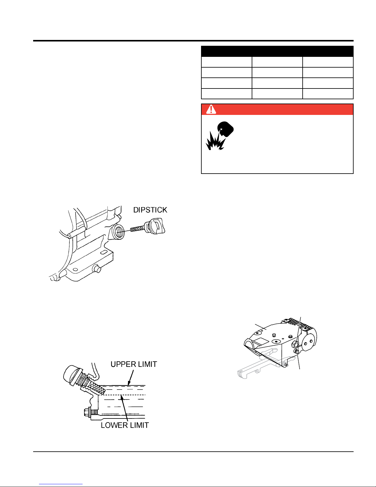
Engine Oil Check
1. To check the engine oil level, place the trowel on secure
level ground with the engine stopped.
2. Remove the dipstick from the engine oil filler hole
(Figure 29) and wipe clean.
Table 4. Oil Type
Season Temperature Oil Type
Summer 25°C or Higher SAE 10W-30
Spring/Fall 25°C~10°C SAE 10W-30/20
Winter 0°C or Lower SAE 10W-10
DANGER
EXPLOSIVE FUEL!
Motor fuels are highly flammable and can
be dangerous if mishandled. DO NOT
smoke while refueling. DO NOT attempt
to refuel the trowel if the engine is hot! or
running.
Fuel Check
1. Visually inspect to see if fuel level is low. If fuel is low,
replenish with unleaded fuel.
2. When refueling, be sure to use a strainer for filtration.
DO NOT top-off fuel. Wipe up any spilled fuel
immediately.
Figure 29. Engine Oil Dipstick Removal
3. Insert and remove the dipstick without screwing it into
the filler neck. Check the oil level shown on the dipstick.
4. If the oil level is low (Figure 30), fill to the edge of the
oil filler hole with the recommended oil type as listed
in Table 4. Reference Table 3 for maximum engine oil
capacity.
Figure 30. Engine Oil Dipstick (Oil Level)
Gearbox Oil
1. Determine if the gearbox oil is low by removing the oil
plug located on the side of the gearbox. (Figure 31)
This plug will be marked by the "check" decal. The
correct level of the lubrication oil should be to the
bottom of the fill plug.
FILL PLUG
DRAIN
Figure 31. Gearbox
2. If lubrication oil begins to seep out as the drain plug
is being removed, then it can be assumed that the
gearbox has a sufficient amount of oil.
PRO46 SERIES WALK-BEHIND TROWEL • OPERATION AND PARTS MANUAL — REV. #1 (8/20/15) — PAGE 29
Page 30

INSPECTION/OPERATION
3. If lubrication oil does not seep out as the drain plug
is being removed, fill with type ISO 680 (P/N 10139)
gearbox lubricant oil until the oil filler hole overflows.
V-Belt Check
A worn or damaged V-belt can adversely affect the
performance of the trowel. If a V-belt is defective or worn
simply replace the V-belt as outlined in the maintenance
section of this manual.
Belt Guard Check
Check for damage, loose or missing hardware.
Blade Check
Check for worn or damaged blades. Check to see if one
blade is worn out while the others look new. If this is
the case there could be a blade pitch problem. Refer to
the maintenance section of this manual for blade pitch
adjustment procedure. Replace any worn blades.
Operation
NOTICE
The trowel is heavy and awkward to move around. Use
proper heavy lifting procedures and DO NOT lift the
trowel by the guard rings.
Lifting Bale
The lift bale provides an optimal lift point for lifting the trowel.
When lifting the trowel onto a concrete slab, attach a chain
or rope to the lifting bale. Make sure the lifting device has
adequate lifting capacity to lift the trowel.
Using a crane or forklift (Figure 32) to lift the trowel is highly
recommended, and is perfectly safe for the trowel. ALWAYS
use extra care when lifting the trowel off the ground.
LIFT
This section is intended to assist the operator with the initial
start-up of the walk-behind trowel. It is extremely important
that this section be read carefully before attempting to use
the trowel in the field. DO NOT use your trowel until this
section is thoroughly understood.
Lifting the Trowel Onto a Slab
Extra care should be taken when lifting the trowel off the
ground. Serious damage to the machine or personal injury
could be caused by dropping a trowel.
WARNING
NEVER attempt to lift this machine alone. NEVER lift
the trowel by the guard ring as it may rotate and cause
injury.
ALWAYS make certain the handle is secure and use
only the manufacturer's approved lifting point. The
trowel may be lifted at the center lifting bale by crane
or other lifting device of adequate capacity.
NOTICE
Figure 32. Lifting the Trowel
NEVER lift the trowel to unnecessary heights. DO NOT
stand underneath the trowel while it is being lifted. Serious
damage to the machine or personal injury could be caused
by dropping a trowel.
DO NOT attempt to operate the trowel until the Safety,
General Information and Inspection sections of this
manual have been read and thoroughly understood.
PAGE 30 — PRO46 SERIES WALK-BEHIND TROWEL • OPERATION AND PARTS MANUAL — REV. #1 (8/20/15)
Page 31

OPERATION
Positioning Boom For Troweling (Side-To-Side)
1. Pull the T-handle (Figure 33) to release the boom from
its locked position.
2. Position the boom arm in the desired position. Boom
can be rotated left or right up to 90°.
3. When positioned, release T-handle.
T-HANDLE
FRESNO
BOOM
FRESNO
STANCHION
NOTCH
180°
FRESNO
STANCHION
Positioning Fresno Brush
1. Pull the spring-loaded pin on both sides of the brush
arm to release the brush (Figure 34).
2. Position the brush as required.
3. Release the spring-loaded pins.
PULL
BRUSH ARM
SPRING-LOADED PIN
Figure 34. Lowering the Fresno Brush
Figure 33. Boom Adjustment (Side-To-Side)
PRO46 SERIES WALK-BEHIND TROWEL • OPERATION AND PARTS MANUAL — REV. #1 (8/20/15) — PAGE 31
Page 32

OPERATION
Lowering and Raising Boom for Troweling
1. Make sure that the fresno blade, fresno brush, and
plated weights (if used) are secure and in the proper
position before lowering or raising the boom.
2. Rotate the crank handle clockwise to lower, and
counterclockwise to raise, the boom (Figure 35).
WINCH
RAISE
(CCW )
LOWER
(CW)
FRESNO BOOM
CRANK
Figure 35. Winch Hand Crank Rotation
2. Place the engine fuel valve lever (Figure 37) in the
"ON" position.
Figure 37. Engine Fuel Valve Lever (ON)
3. Place the throttle lever (Figure 38) in the "idle" position.
IDLE
THROTTLE
LEVER
Starting the Engine
1. Turn the engine start/stop switch to the "ON" position
(Figure 36).
Figure 36. Engine ON/OFF Switch
(ON Position)
Figure 38. Throttle (Idle Position)
PAGE 32 — PRO46 SERIES WALK-BEHIND TROWEL • OPERATION AND PARTS MANUAL — REV. #1 (8/20/15)
Page 33

OPERATION
4. Place the choke lever (Figure 39) in the "OPEN"
position.
Figure 39. Choke Lever Open
5. Grasp the starter grip (Figure 40) and slowly pull it
out. The resistance becomes the hardest at a certain
position, corresponding to the compression point. Pull
the starter grip briskly and smoothly for starting.
6. If the engine has started, slowly return the choke lever
(Figure 41) to the CLOSED position. If the engine has
not started repeat steps 1 through 5.
Figure 41. Choke Lever Closed
7. Before the trowel is placed into operation, run the
engine for several minutes. Check for fuel leaks, and
noises that would associate with a loose guard ring
and/or covers.
Figure 40. Starter Grip
To Begin Troweling
1. To begin troweling, place the throttle lever (Figure 42) in
the "RUN" position.
RUN
THROTTLE
LEVER
Figure 42. Throttle Lever (Run)
PRO46 SERIES WALK-BEHIND TROWEL • OPERATION AND PARTS MANUAL — REV. #1 (8/20/15) — PAGE 33
Page 34

OPERATION
BLADE PITCH
2. Squeeze the clutch lever (Figure 43) to begin troweling.
Verify that the blades are rotating.
NOTICE
When engaging the clutch lever, make sure to keep
hands clear of the clutch lever engagement arc/path
to prevent pinching and/or bodily harm as indicated in
Figure 43.
CLUCTH LEVER
ENGAGEMENT
ARC/PATH
RIGHT CLUTCH
LEVER
PINCH
POINT
PINCH
POINT
PINCH
POINT
PINCH
POINT
LEFT CLUTCH
LEVER
PINCH
POINT
Concrete Finishing Techniques
The following steps are intended as a basic guide to
machine operation, and are not to be considered a complete
guide to concrete finishing. We suggest that all operators
(experienced and novice) read “Slabs on Grade” published by
the American Concrete Institute, Detroit, Michigan. Read
the “Training” section of this manual for more information.
Pitching the Blades (Standard Handle)
To pitch the blades upwards, (Figure 44) simply turn the
star wheel clockwise. Turning the star wheel counterclockwise
will cause the blades to lay flat.
4-BLADE STAR
WHEEL PITCH KNOB
Figure 43. Clutch Levers (Blade Activation)
STAR WHEEL
INCREASE
(CW)
DECREASE
BLADE PITCH
(CCW)
Figure 44. 4-Blade Pitch Star Wheel
PAGE 34 — PRO46 SERIES WALK-BEHIND TROWEL • OPERATION AND PARTS MANUAL — REV. #1 (8/20/15)
Page 35

OPERATION
Maneuvering the Trowel
1. Get into the operator’s position behind the handlebar.
With a secure foothold and a firm grasp on the
handlebar, slowly increase the engine speed until the
desired blade speed is obtained.
2. Figure 45 below illustrates a typical walk-behind trowel
application. Practice maneuvering the trowel. The trick
is to let the trowel do the work.
3. Continue to practice maneuvering the trowel. Try to
practice as if you were finishing a slab of concrete.
Practice edging and covering a large area.
Remember a good finishing technique is to work
backwards or laterally. Be careful when moving
backwards or laterally so that hazards can be avoided.
The best way to get accustomed to the trowel is
repeated use.
4. After the initial troweling pass, bring the trowel to a
clean troweled section.
5. Rotate the winch clockwise to lower the fresno blade
and brush to the troweling surface.
6. Slowly walk backwards or laterally to guide the trowel in
a straight path. Make sure the fresno blade and brush
follow the path of the trowel. This will cover all footprints
and troweling marks on wet surfaces.
7. Rotate the winch counterclockwise to raise the fresno
blade and brush at the end of the troweling path. If
troweling laterally, rotate the boom to the opposite side
between passes before beginning a new pass.
8. Repeat Steps 4-7 until the troweling surface is
completely finished.
CAUTION
NEVER place your feet or hands inside the guard rings
while starting or operating this equipment.
CAUTION
ALWAYS keep clear of rotating or moving parts while
operating this equipment.
To move the trowel to the operator’s
left, lift up on the handle, to move the
trowel to the right push down on the
handle.
Remember! that if you let go
of the trowel, just step away
and let the trowel come to a
complete STOP before trying
to recover the trowel.
Remember! that if you let go
of the clutch lever, just step away
as the trowel will stop immediately.
LATERALLY
BACKWARDS
Figure 45. Maneuvering the Trowel
BACKWARDS
LATERALLY
The best method for finishing concrete is to
slowly walk backwards with the trowel, guiding
the trowel from side to side. This will cover all
footprints on wet concrete.
PRO46 SERIES WALK-BEHIND TROWEL • OPERATION AND PARTS MANUAL — REV. #1 (8/20/15) — PAGE 35
Page 36

OPERATION
Stopping The Engine
1. Move the throttle lever to the (Figure 46) "IDLE"
position and run the engine for three minutes at low
speed.
IDLE
THROTTLE
LEVER
Figure 46. Throttle Lever (Idle)
3. Close the fuel shut- off valve (Figure 48) by moving the
fuel valve lever to the OFF position.
Figure 48. Fuel Valve Lever (OFF)
2. After the engine cools, turn the engine start/stop switch
to the “OFF” position (Figure 47).
Figure 47. Engine ON/OFF Switch
(OFF Position)
PAGE 36 — PRO46 SERIES WALK-BEHIND TROWEL • OPERATION AND PARTS MANUAL — REV. #1 (8/20/15)
Page 37

OPTIONS
NOTICE
Trowel blades should be changed when they fail to finish
concrete in a satisfactory manner.
Blades are a vital part of finishing concrete. This trowel,
or finisher, has been designed to finish concrete and the
blades are built to stringent quality standards out of the
finest steel.
If you need replacement blades, consult the parts list in
this manual for part numbers and order them from your
Multiquip parts dealer or importer.
Combo Blades
This trowel is equipped with combination float/finish
(Figure 49) blades as original equipment. These blades
have been designed for optimum performance in both the
floating and finishing operations. These blades are versatile
and should take care of most troweling needs.
Clip-On Float Blades (Optional)
These blades will clip (Figure 51) onto an existing installed
blade, allowing your finisher to float on “wet” concrete so
that the troweling operation can begin as early as possible.
These blades are easily removable, so that after the floating
operation, when the concrete is sufficiently cured, they
can be removed to expose the finish blades for continued
troweling.
Figure 51. Clip-On Float Blade
Float Discs (Optional)
These round discs (Figure 52) attach to the spiders and
allow the machine to “float” on “wet” concrete. The disc
design allows early floating and easy movement from wet
to dry areas. They are also very effective in embedding
large aggregates and surface hardeners.
Figure 49. Combination Blade
Finish Blades (Optional)
These blades (Figure 50) have been specifically designed
for finish operations with this trowel. They will provide a
premium surface finishing capability from your trowel.
They should only be used after the concrete has set to
the point where the trowel does not sink into the concrete
when placed on it.
Figure 50. Finish Blade
Figure 52. Float Disc/Pan
PRO46 SERIES WALK-BEHIND TROWEL • OPERATION AND PARTS MANUAL — REV. #1 (8/20/15) — PAGE 37
Page 38

OPTIONS
Trowel Arm Adjustment Tool (Optional)
If blades show uneven wear patterns or some tend to
wear out faster than others, the trowel arms may need to
be adjusted. A special tool is available (Figure 53) that will
adjust all of the trowel arms consistently. The Trowel Arm
Fixture P/N is 1817.
Figure 53. Trowel Arm Adjustment Fixture
FRESNO BRUSHES
NOTICE
Fresno brushes should be changed when they fail to
finish concrete in a satisfactory manner.
Fresno brushes are a vital part of finishing concrete. The
fresno brush is designed to finish concrete with a textured,
or decorative, look using the sides of the brush bristles, not
the ends. There are three different color-coded, textured
(stiffness) brushes compatible with this trowel unit: soft
(black), medium (orange), stiff (green).
If you need a replacement brush, or want a different
finished look to the troweling surface, consult the parts list
in this manual for part numbers and order them from your
Multiquip parts dealer or importer.
PAGE 38 — PRO46 SERIES WALK-BEHIND TROWEL • OPERATION AND PARTS MANUAL — REV. #1 (8/20/15)
Page 39

Table 5. Engine Maintenance Schedule
MAINTENANCE
EVERY
YEAR
OR 300
HRS.
DESCRIPTION
(3)
OPERATION
BEFORE
EACH
USE
FIRST
MONTH OR
20 HRS.
EVERY 6
MONTHS
OR 100
HRS.
Check X
Engine Oil
Change X X
Engine Oil Filter Replace Every 200 Hrs.
Check X
Air Cleaner
Clean X (1)
Change X (*)
Check/Adjust X
Spark Plugs
Replace X
Spark Arrester Clean X
Fuel Filter Replace X (2)
Fuel Tube Check Every 2 years (replace if necessary) (2)
* - Replace the paper filter element only.
(1) Service more frequently when used in DUSTY areas.
EVERY 2
YEARS OR
500 HRS.
(2) These items should be serviced by your service dealer, unless you have the proper tools and are mechanically proficient.
Refer to the HONDA Shop Manual for service procedures.
(3) For commercial use, log hours of operation to determine proper maintenance intervals.
Table 6. Trowel Maintenance Schedule
Periodic Maintenance Interval
ITEM OPERATION DAILY
Every
50-60 Hrs
Every
200-300 Hrs
Every
2000-2500 Hrs
V-Belt Check/Replace X
Relube Trowel Arms Grease X
Blades Check/Replace X
Trowel Arms Remove/Clean X
Thrust Collar/Bushing Remove/Clean X
Blade Arms Adjust X
Arm Bushing Remove/Replace X
Wear Ring Remove/Replace X
Thrust Collar Bearing Remove/Replace X
Pitch Control Cable Check X
Clutch Remove/Clean X
PRO46 SERIES WALK-BEHIND TROWEL • OPERATION AND PARTS MANUAL — REV. #1 (8/20/15) — PAGE 39
Page 40

MAINTENANCE
BLOW COMPRESSED
AIR FROM THE
INSIDE OUT
General maintenance practices are crucial to the
performance and longevity of your trowel. This equipment
requires routine cleaning, blade and trowel arm inspection,
lubrication and V-belt inspection for wear and damage.
Reference Table 5 and Table 6 for scheduled engine and
trowel maintenance.
The following procedures, devoted to maintenance, can
prevent serious trowel damage or malfunctioning.
NOTICE
Reference HONDA engine manual supplied with your
trowel for more detailed engine maintenance and
troubleshooting.
CAUTION
ALWAYS allow the engine to cool before
servicing. NEVER attempt any maintenance
work on a hot engine.
CAUTION
ALWAYS disconnect the spark plug wire from the spark
plug and secure away from the engine before performing
maintenance or adjustments on the machine.
Engine Air Cleaner
DANGER
DO NOT use gasoline or low flash point
solvents for cleaning the air cleaner, the
possibility exists of fire or explosion which
can cause damage to the equipment and
severe bodily harm or even DEATH!
CAUTION
Wear protective equipment such as
approved safety glasses or face shields
and dust masks or respirators when
cleaning air filters with compressed air.
This engine is equipped with a replaceable, high-density
paper air cleaner element. See Figure 54 for air cleaner
components.
1. Remove the air cleaner cover and foam filter element.
2. Tap the paper filter element several times on a hard
surface to remove dirt, or blow compressed air not
exceeding 30 psi (207 kPa, 2.1 kgf/cm2) through the
filter element from the inside out. NEVER brush off
dirt. Brushing will force dirt into the fibers. Replace the
paper filter element if it is excessively dirty.
WARNING
Some maintenance operations may
require the engine to be run. Ensure
that the maintenance area is well
ventilated. Gasoline engine exhaust
contains poisonous carbon monoxide
gas that can cause unconsciousness
and may result in DEATH.
GENERAL CLEANLINESS
Clean the trowel daily. Remove all dust and slurry buildup.
If the trowel is steam-cleaned, ensure that lubrication is
accomplished AFTER steam cleaning.
ENGINE CHECK
Check daily for any oil and/or fuel leakage, thread nut and
bolt tightness, and overall cleanliness.
3. Clean foam element in warm, soapy water or
nonflammable solvent. Rinse and dry thoroughly. Dip
the element in clean engine oil and completely squeeze
out the excess oil from the element before installing.
Figure 54. Engine Air Cleaner
PAGE 40 — PRO46 SERIES WALK-BEHIND TROWEL • OPERATION AND PARTS MANUAL — REV. #1 (8/20/15)
Page 41

MAINTENANCE
GAP
IN.
)
NOTICE
Operating the engine with loose or damaged air cleaner
components could allow unfiltered air into the engine
causing premature wear and failure.
ENGINE OIL
1. Drain the engine oil when the oil is warm as shown in
Figure 55.
2. Remove the oil drain bolt and sealing washer and allow
the oil to drain into a suitable container.
3. Replace engine oil with recommended type oil as listed
in Table 4. For engine oil capacity, see Table 3 (engine
specifications). DO NOT overfill.
4. Reinstall drain bolt with sealing washer and tighten
securely.
SPARK PLUG
NOTICE
NEVER use a spark plug of incorrect heat range.
1. Remove and clean spark plug (Figure 56) with a wire
brush if it is to be reused. Discard spark plug if the
insulator is cracked or chipped.
2. Using a feeler gauge adjust spark plug gap to
0.028 ~0.031 inch (0.7~0.8 mm).
3. Thread spark plug into cylinder hole by hand to prevent
cross-threading, then tighten securely.
.028 - .031
(0.7- 0.8 MM.
Figure 55. Draining Engine Oil
Figure 56. Spark Plug Gap
V-BELT
Visually examine the V-belt (Figure 57) and determine if it
is full of tiny cracks, frayed, has pieces of rubber missing,
is peeling or otherwise damaged.
Also, examine the belt and determine if it is oil soaked or
"glazed " (hard shiny appearance on the sides of the belt).
Either of these two conditions can cause the belt to run hot,
which can weaken it and increase the danger of it breaking.
PRO46 SERIES WALK-BEHIND TROWEL • OPERATION AND PARTS MANUAL — REV. #1 (8/20/15) — PAGE 41
Page 42

MAINTENANCE
OIL SOAKED
MISSING RUBBER
WEAR
SCREEN
WIRE
BRUSH
If the V-belt exhibits any of the above wear conditions
replace the V-belt immediately.
GLAZED
CRACKS
SIDEWALL
Figure 57. V-Belt Inspection
CORD FAILURE
WORN BACK
COVER
BROKEN
SPARK ARRESTER CLEANING
3. Remove the 4 mm screw from the spark arrestor, then
remove the spark arrester.
Figure 58. Spark Arrester Removal
4. Carefully remove carbon deposits from the spark
arrester screen (Figure 59) with a wire brush.
Clean the spark arrester every 6 months or 100 hours.
1. Remove the 4 mm screw (3) from the exhaust deflector,
then remove the deflector. See Figure 58.
2. Remove the 5 mm screw (4) from the muffler protector,
then remove the muffler protector.
SPARK
ARRESTER
Figure 59. Cleaning The Spark Arrester
5. If the spark arrester is damaged and has breaks or
holes, replace with a new one.
6. Reinstall the spark arrester and muffler protector in
reverse order of disassembly.
PAGE 42 — PRO46 SERIES WALK-BEHIND TROWEL • OPERATION AND PARTS MANUAL — REV. #1 (8/20/15)
Page 43

BLADE PITCH
BLADE
MAINTENANCE
BOLT
FINISHED CONCRETE
PITCH
4-BLADE PITCH ADJUSTMENT PROCEDURE
The maintenance adjustment of blade pitch is an adjustment
that is made by a bolt (Figure 60) on the arm of the trowel
arm lever. This bolt is the contact point of the trowel arm
lever to the lower wear plate on the thrust collar. The goal
of the adjustment is to promote consistent blade pitch and
finishing quality. Adjustments are made by tightening or
loosening the blade pitch adjustment bolt.
ADJUSTMENT
BOLT
TROWEL LEVER
FINGER
TROWEL
ARM
SPIDER
PLATE
TROWEL
Figure 60. Blade Pitch Adjustment Bolt
Watch for the following indications when determining if
blade pitch adjustments are necessary:
• Is the machine wearing out blades unevenly, (i.e. one
blade is completely worn out while the others look
new)?
• Does the machine have a perceptible rolling or
bouncing motion when in use?
• Look at the machine while it is running, do the guard
rings “rock up and down” relative to the ground?
If it is determined that blade pitch adjustments are required,
do the following:
NOTICE
Before any blade pitch adjustments can be made
it is essential to have a clean level area free of dirt
and debris to test the trowel. Any unlevel spots in the
floor or debris under the trowel blades will give an
incorrect perception of adjustment. Ideally, a 5 x 5 ft.
(1.5 x 1.5 meter), three-quarter inch (19 mm) thick FLAT
steel plate should be used for testing.
2. Pitch the blades as flat as possible. The pitch
adjustment bolts (Figure 61) should all barely make
contact (0.10 inch max. clearance) with the lower
wear plate on the spider. All pitch alignment bolts
should be spaced the same distance from the lower
wear plate. If one is not making contact, adjustment
will be necessary.
GEARBOX
TROWEL
ARM
STEEL TEST
SURFACE
PITCH
ADJUSTMENT
LOWER
WEAR PLATE
MOUNTING
BAR
BLADE
Figure 61. Correct Blade Pitch (Flat)
3. Adjust the “high” bolts down to the level of the one that
is not touching, or adjust the “low” bolt up to the level
of the higher ones. If possible, adjust the low bolt up
to the level of the rest of the bolts. This is the fastest
way, but may not always work. Verify after adjustment
the blades pitch correctly.
4. Blades that are incorrectly adjusted often will not be
able to pitch flat. This can occur if the adjusting bolts
are raised too high. Conversely, adjusting bolts that
are too low will not allow the blades to be pitched high
enough for finishing operations.
5. If, after making blade pitch adjustments the machine
is still finishing poorly, blades, trowel arms, and trowel
arm bushings may be suspect and should be looked
at for adjustment, wear, or damage.
6. Figure 62 illustrates, "incorrect alignment", worn spider
bushings or bent trowel arms.
ADJUSTMENT
BOLT
NO
LOWER
WEAR PLATE
“DISHED” EFFECT ON
1. Place the trowel on a flat, level area free of dirt and
debris.
PRO46 SERIES WALK-BEHIND TROWEL • OPERATION AND PARTS MANUAL — REV. #1 (8/20/15) — PAGE 43
Figure 62. Incorrect Spider Plate Alignment
Page 44

GEARBOX
ARM
MAINTENANCE
BLADE
AT
SPIDER REMOVAL
Remove the spider assembly from the gearbox shaft as
follows:
1. Locate the cone point square head set screw
(Figure 63) and attached jam nut found on the side of
the spider assembly.
2. Loosen the jam nut and cone point square head set
screw.
3. Carefully lift the upper trowel/gearbox assembly off of
the spider assembly. A slight tap with a rubber mallet
may be necessary to dislodge the spider from the main
shaft of the gearbox.
YOKE
GEARBOX
SHAFT
THRUST COLLAR
BEARING
CHANGING BLADES
It is recommended that ALL the blades on the trowel
are changed at the same time. If only one or some of the
blades are changed, the machine will not finish concrete
consistently and the machine may wobble or bounce.
Perform the following procedure when changing blades:
Please note the blade orientation on the trowel arm before
removing.
1. Lift the trowel up, placing blocks under the main guard
ring to support it.
2. Remove the bolts and lock washers from all the
towel arms, and then remove the blades as shown in
Figure 64.
ATTACHMENT
SCREWS
TROWEL ARM
SET SCREW
(CONE POINT SQ.HD.)
Figure 63. Spider Removal
JAM
NUT
WEAR RING
THRUST COLLAR
W/BUSHING
LOWER WEAR
PLATE
SPIDER PLATE
BLADE
TACHMENT
BAR
TROWEL
BLADE
Figure 64. Blade Removal
3. Wire brush and remove all concrete and debris from
all six sides of each of the four trowel arms. This is
important to properly seat the new blades.
4. Install the new blades, maintaining the proper blade
orientation for direction of rotation.
5. Reinstall the bolts and lock washers.
PAGE 44 — PRO46 SERIES WALK-BEHIND TROWEL • OPERATION AND PARTS MANUAL — REV. #1 (8/20/15)
Page 45

MAINTENANCE
F HEXAGONAL
LEVER
MOUNTING
SHAFT SECTION
TROWEL
TROWEL
TEST
(.004 IN/0.10 MM)
(.005 IN/0.127 MM)
TROWEL ARM REMOVAL
1. Each trowel arm is held in place at the spider plate
by a hex head bolt (zerk grease fitting) and a roll
pin. Remove both the hex head bolt and the roll
pin (Figure 65) from the spider plate.
2. Remove the trowel arm from the spider plate.
3. Should the trowel arm inserts ( bushing ) come out with
the trowel arm, remove the bushing from the trowel arm
and set aside in a safe place. If the bushing is retained
inside the spider plate, carefully remove the bushing.
4. Examine the trowel arm bushing insert (Figure 65),
clean if necessary. Replace bushing if out of round
or worn.
SPIDER PLATE
ROLL PIN
TROWEL
ARM
CAP
ZERK
GREASE
FITTING
BUSHING
CHECKING TROWEL ARM STRAIGHTNESS
Trowel arms (Figure 66) can be damaged by rough
handling, such as dropping the trowel on the pad, or
by striking exposed plumbing, forms, or rebar while in
operation. A bent trowel arm will not allow the trowel to
operate in a smooth fluid rotation. If bent trowel arms are
suspect, check for flatness as follows:
SLOT
TROWEL ARM
ROUND SHAFT
SECTION
ROLL PIN
HOLE
HEXAGONAL (HEX)
Figure 66. Trowel Arm
1. Use a thick steel plate, granite slab or any surface
which is true and flat, to check all six sides of each
trowel arm for flatness (Figure 67).
2. Check each of the six sides of the trowel arm (hex
section). A feeler gauge of .004 inch (0.10 mm) should
not pass between the flat of the trowel arm and the test
surface along its length on the test surface.
BLADE ATTACHMENT
BOLT HOLE
FLATO
SHAFT (TOP OF ARM)
TROWEL ARM
Figure 65. Trowel Arm Removal
ARM
ARM
FEELER GAUGE
FEELER GAUGE
FLAT
SURFACE
Figure 67. Checking Trowel Arm Flatness
3. Next, check the clearance between the round shaft
and the test surface as one of the flat hex sections of
the arm rests on the test surface. Rotate the arm to
each of the flat hex sections and check the clearance
of the round shaft. Use a feeler gauge (Figure 68) of
.005 inch (0.127 mm). Each section should have the
same clearance between the round of the trowel arm
shaft and the test surface.
4. If the trowel arm is found to be uneven or bent, replace
the trowel arm.
PRO46 SERIES WALK-BEHIND TROWEL • OPERATION AND PARTS MANUAL — REV. #1 (8/20/15) — PAGE 45
Page 46

MAINTENANCE
SHIM
ADJUSTMENT FIXTURE
TROWEL
ANCE
TROWEL ARM LEVER ADJUSTMENT
The easiest and most consistent way to adjust the trowel
arm lever is to use the Trowel Arm Adjustment Fixture
(P.N. 1817).
As each trowel arm is locked into the fixture, the arm bolt
is adjusted to where it contacts a stop on the fixture. This
will consistently adjust all of the trowel arms, keeping the
finisher as flat and evenly pitched as possible.
This fixture will allow consistent adjustment of the trowel
arm lever. It comes with all the hardware necessary to
properly accomplish this maintenance and instructions on
how to properly utilize this tool. Adjusting the trowel arm
lever without a fixture requires a special talent.
Perform the following procedure when adjusting the trowel
arm lever:
1. Unscrew the locking bolts on the adjustment fixture and
place the trowel arm (lever attached) into the fixture
channel as shown in Figure 68.
2. Ensure the fixture arm is in the up position.
3. A thin shim may be required to cover the blade holes on
the trowel arm. Make sure to align the trowel adjustment
bolt with the fixture adjustment bolt.
ARM
LOCKING
BOLTS
ARM
LEVER
TROWEL ARM
FIXTURE
ARM
ADJUSTMENT
ADJUSTMENT
BOLT
DIST
.010 INCH
BOLT
6. Loosen the locking nut on the trowel arm lever, then
turn the trowel arm adjusting bolt until it barely touches
(.010") the fixture adjusting bolt.
7. Once the correct adjustment is made, tighten the lock
nut on the trowel arm to lock in place.
8. Loosen locking nuts on the adjustment fixture, and
remove trowel arm.
9. Repeat steps for the remaining trowel arms.
REASSEMBLY
1. Clean and examine the upper/lower wear plates and
thrust collar. Examine the entire spider assembly. Wire
brush any concrete or rust buildup. If any of the spider
components are found to be damaged or out of round,
replace them.
2. Make sure that the bronze trowel arm bushing is
not damaged or out of round. Clean the bushing if
necessary. If the bronze bushing is damaged or worn,
replace it.
3. Reinstall bronze bushing onto trowel arm.
4. Repeat steps 2 -3 for each trowel arm.
5. Make sure that the spring tensioner is in the correct
position to exert tension on the trowel arm.
6. Insert all trowel arms with levers into spider plate (with
bronze bushing already installed) using care to align
grease hole on bronze bushing with grease hole fitting
on spider plate.
7. Lock trowel arms in place by tightening the hex head
bolt with zerk grease fitting and jam nut.
8. Reinstall the blades onto the trowel arms.
9. Install stabilizer ring onto spider assembly.
Figure 68. Trowel Arm Adjustment Fixture
4. Use an allen wrench to tighten the locking bolts
securing the trowel arm in place.
5. Adjust the bolt distance shown in Figure 68 to match
one of the arms. The other arms will be adjusted to
match this distance.
PAGE 46 — PRO46 SERIES WALK-BEHIND TROWEL • OPERATION AND PARTS MANUAL — REV. #1 (8/20/15)
10. Reinstall lower wear plate, thrust collar and upper wear
ring in the reverse order that they were disassembled
onto the spider shaft. Make sure that there is little or
no lateral movement between the thrust collar and the
spider shaft.
11. Carefully lift the upper trowel assembly, line up the
keyway on gear box main shaft and insert into spider
assembly.
Page 47

MAINTENANCE
Y
KNOB,
Z-CLIP
12. Reinstall square head cone point into spider plate and
tighten in place. Tighten jam nut. Use care in making
sure point of set screw engages groove in gear box
main shaft.
13. Lubricate all grease points (zerk fittings) with premium
"Lithium 12" based grease, conforming to NLG1 Grade
#2 consistency.
INSTALLING PANS ONTO FINISHER BLADES
These round discs, sometimes referred to as "pans", attach
to the spiders arms and allow early floating on wet concrete
and easy movement from wet to dry areas. They are also
very effective in embedding large aggregates and surface
hardeners.
Refer to Figure 69 when installing pans onto finisher blades.
TIE-DOWN
PANS
TIE-DOWN, BLADE
LONG-TERM STORAGE
For storage of the trowel for over 30 days, the following is
required:
Drain the fuel tank completely, or add STA-BIL to the fuel.
Run the engine until the gasoline in the carburetor is
completely consumed.
Completely drain the oil from the crankcase and refill
with fresh oil.
Remove the spark plug. Pour 5 to 10 cc of SAE 30 oil
into the cylinder. Turn the engine switch to the START
position for a few seconds to distribute the oil. Reinstall
the spark plug.
Clean all external parts of the trowel with a cloth.
Cover the trowel and store in a clean, dry place.
Z-CLIP, PAN
Figure 69. Z-Clip Finisher Pan Installation
BLADE ASSEMBL
1. Lift trowel just enough to slide pan under blades. Lower
finisher onto pan with blades adjacent to Z-Clips.
2. Rotate blades into position under Z-Clips. Ensure that
the blades are rotated in the direction of travel when
the machine is in operation or use the engine to rotate
the blades into position.
3. Attach the blade tie-downs to the far side of the Z-Clip
brackets with tie-down knobs as shown in Figure 69.
4. Check to make certain that the blade edges are
secured under the Z-Clips and the tie-downs are
secured completely over the edges of the blade bar
before the machine is put back into operation.
PRO46 SERIES WALK-BEHIND TROWEL • OPERATION AND PARTS MANUAL — REV. #1 (8/20/15) — PAGE 47
Page 48

Symptom Possible Problem Solution
Diffi cult to start, fuel is available, but no spark
at spark plug.
Diffi cult to start, fuel is available, and spark is
present at the spark plug.
Diffi cult to start, fuel is available, spark is
present and compression is normal.
Diffi cult to start, fuel is available, spark is
present and compression is low.
No fuel present at carburetor.
TROUBLESHOOTING
Troubleshooting (Engine)
Spark plug bridging? Check gap, insulation or replace spark plug.
Carbon deposit on spark plug? Clean or replace spark plug.
Short circuit due to defi cient spark plug
insulation?
Improper spark plug gap? Set to proper gap.
Fuel reaching carburetor? Check fuel line.
Water in fuel tank? Flush or replace fuel tank.
Fuel fi lter clogged? Replace fuel fi lter.
Stuck carburetor? Check fl oat mechanism.
Spark plug is red? Check transistor ignition unit.
Spark plug is bluish white?
No spark present at tip of spark plug?
No oil? Add oil as required.
Oil pressure alarm lamp blinks upon starting?
(if applicable)
ON/OFF switch is shorted? Check switch wiring, replace switch.
Ignition coil defective? Replace ignition coil.
Improper spark gap, points dirty? Set correct spark gap and clean points.
Condenser insulation worn or short circuiting? Replace condenser.
Spark plug wire broken or short circuiting? Replace defective spark plug wiring.
Wrong fuel type?
Water or dust in fuel system? Flush fuel system.
Air cleaner dirty? Clean or replace air cleaner.
Choke open? Close choke.
Suction/exhaust valve stuck or protruded? Reseat valves.
Piston ring and/or cylinder worn? Replace piston rings and/or piston.
Cylinder head and/or spark plug not tightened
properly?
Head gasket and/or spark plug gasket damaged? Replace head and spark plug gaskets.
No fuel in fuel tank? Fill with correct type of fuel.
Fuel cock does not open properly?
Fuel fi lter/lines clogged? Replace fuel fi lter.
Fuel tank cap breather hole clogged? Clean or replace fuel tank cap.
Air in fuel line? Bleed fuel line.
Check spark plug insulation, replace if worn.
If insuffi cient compression, repair or replace
engine. If injected air leaking, correct leak. If
carburetor jets clogged, clean carburetor.
Check transistor ignition unit is broken, and
replace defective unit. Check if voltage cord
cracked or broken and replace. Check if
spark plug if fouled and replace.
Check automatic shutdown circuit, "oil
sensor". (if applicable)
Flush fuel system, and replace with correct
type of fuel.
Torque cylinder head bolts and spark plug.
Apply lubricant to loosen fuel cock lever,
replace if necessary.
PAGE 48 — PRO46 SERIES WALK-BEHIND TROWEL • OPERATION AND PARTS MANUAL — REV. #1 (8/20/15)
Page 49

Symptom Possible Problem Solution
Weak in power, compression is proper and
does not misfi re.
Weak in power, compression is proper but
misfi res.
Engine overheats.
Rotational speed fl uctuates.
Recoil starter malfunctions. (if applicable)
Starter malfunctions.
Burns too much fuel.
Exhaust color is continuously "white".
Exhaust color is continuously "black".
Will not start, no power with ON/OFF switch
in "ON" position.
TROUBLESHOOTING
Troubleshooting (Engine) - continued
Air cleaner dirty? Clean or replace air cleaner.
Improper level in carburetor? Check fl oat adjustment, rebuild carburetor.
Defective spark plug? Clean or replace spark plug.
Improper spark plug? Set to proper gap.
Water in fuel system?
Dirty spark plug? Clean or replace spark plug.
Ignition coil defective? Replace ignition coil.
Spark plug heat value incorrect? Replace with correct type of spark plug.
Wrong type of fuel? Replace with correct type of fuel.
Cooling fi ns dirty? Clean cooling fi ns.
Intake air restricted?
Oil level too low or too high? Adjust oil to proper level.
Governor adjusted incorrectly? Adjust governor.
Governor spring defective? Replace governor spring.
Fuel fl ow restricted? Check entire fuel system for leaks or clogs.
Recoil mechanism clogged with dust and
dirt?
Spiral spring loose? Replace spiral spring.
Loose, damaged wiring?
Battery insuffi ciently charged? Recharge or replace battery.
Starter damaged or internally shorted? Replace starter.
Over-accumulation of exhaust products?
Wrong spark plug?
Lubricating oil is wrong viscosity? Replace lubricating oil with correct viscosity.
Worn rings? Replace rings.
Air cleaner clogged? Clean or replace air cleaner.
Choke valve set to incorrect position? Adjust choke valve to correct position.
Carburetor defective, seal on carburetor
broken?
Poor carburetor adjustment, engine runs too
rich?
ON/OFF switch not activated ON? Turn on ON/OFF Switch.
ON/OFF switch/wiring defective? Replace ON/OFF switch. Check wiring.
Centrifugal stop switch not activated ON? Turn on centrifugal stop switch.
Centrifugal stop switch/wiring defective? Replace centrifugal stop switch. Check wiring.
Flush fuel system and replace with correct
type of fuel.
Clear intake of dirt and debris. Replace air
cleaner elements as necessary.
Clean recoil assembly with soap and water.
Ensure tight, clean connections on battery
and starter.
Check and clean valves. Check muffl er and
replace if necessary.
Replace spark plug with manufacturer's
suggested type.
Replace carburetor or seal.
Adjust carburetor.
PRO46 SERIES WALK-BEHIND TROWEL • OPERATION AND PARTS MANUAL — REV. #1 (8/20/15) — PAGE 49
Page 50

Symptom Possible Problem Solution
Engine running rough or not at all.
Trowel bounces, rolls concrete, or makes
uneven swirls in concrete.
TROUBLESHOOTING
Troubleshooting (Walk-Behind Trowel)
Engine ON/OFF Switch in "OFF" position
or malfunctioning?
Centrifugal ON/OFF Switch in "OFF"
position or malfunctioning?
Fuel?
Ignition?
Loose wire connections Check wiring. Replace or repair as necessary.
Bad contacts in ON/OFF switch? Replace ON/OFF switch.
Blades?
Pitch adjustment?
Bent trowel arms?
Spider?
Thrust collar?
Thrust collar bushing?
Thrust bearing worn?
Make sure that the Engine ON/OFF Switch is ON
or replace switch if necessary.
Place centrifugal stop switch in "ON" position.
Check wiring. Replace switch if necessary.
Look at the fuel system. Make sure there is fuel
being supplied to the engine. Check to ensure that
the fuel fi lter is not clogged.
Check to ensure that the ignition switch has power
and is functioning correctly.
Make certain blades are in good condition, not
excessively worn. Finish blades should measure
no less than 2"" (50mm) from the blade bar to
the trailing edge, combo blades should measure
no less that 3.5"" (89mm). Trailing edge of blade
should be straight and parallel to the blade bar.
Check that all blades are set at the same
pitch angle as measured at the spider. A fi eld
adjustment tool is available for height adjustment
of the trowel arms. (Contact Parts Dept.)
Check the spider assembly for bent trowel arms.
If one of the arms is even slightly bent, replace it
immediately.
Check fi t of arms in spider. This can be done by
moving the trowel arms up and down. If there is
more than 1/8 inch (3.2 mm) of travel at the tip of
the arm, the spider and arms should be replaced.
Check the fl atness of the thrust collar by rotating
it on the spider. If it varies by more than 0.02 inch
(0.5 mm) replace the thrust collar.
Check the thrust collar by rocking it on the spider.
If it can tilt more than 3/32 inch (2.4 mm) - as
measured at the thrust collar O.D., replace the
thrust collar.
Check the thrust bearing to see that it is spinning
freely. Replace if necessary.
PAGE 50 — PRO46 SERIES WALK-BEHIND TROWEL • OPERATION AND PARTS MANUAL — REV. #1 (8/20/15)
Page 51

TROUBLESHOOTING
assembly should be checked for straightness.
Troubleshooting (Walk-Behind Trowel) - continued
Symptom Possible Problem Solution
The main output shaft of the gearbox
Machine has a perceptible rolling motion
while running.
Clutch slipping or sluggish response to
engine speed change.
Trowel blades do not rotate.
Main shaft?
Yoke?
Blade Pitch?
Worn V-belts? Replace V-belt.
Hand clutch out of adjustment?
Worn or defective hand clutch parts? Replace parts as necessary.
Worn bearings in gearbox?
Worn or broken gears in gearbox?
Defective clutch? Replace clutch.
Broken V-belt? Replace V-belt.
Defective ON/OFF switch?
Defective centrifugal ON/OFF switch?
The main shaft must run straight and cannot
be more than 0.003"" (0.08 mm) out of round
at the spider attachment point.
Check to make sure that both fi ngers of the
yoke press evenly on the wear cap. Replace
yoke as necessary.
Check to ensure that each blade is adjusted
to have the same pitch as all other blades.
Adjust per maintenance section in manual.
Adjust per instructions in maintenance
section of this manual.
Rotate input shaft by hand. If shaft rotates
with diffi culty, check the input and output
shaft bearings. Replace as necessary.
Verify that the gearbox shaft rotates when
the input shaft is rotated. Replace both the
worm and worm gear as a set.
Check and replace ON/OFF switch if
necessary.
Check and replace centrifugal ON/OFF
switch if necessary.
PRO46 SERIES WALK-BEHIND TROWEL • OPERATION AND PARTS MANUAL — REV. #1 (8/20/15) — PAGE 51
Page 52

RECOIL
STARTER
COVER
SCREW
BLK BLK
WIRING DIAGRAM
OIL LEVEL
SWITCH
OIL LEVEL
INDICATOR
GRN
YEL
BLK
BLK
YEL
OIL ALERT
UNIT
SPLICE TAP
CONNECTOR
BLK
CHASSIS
GND.
ENGINE
STOP
SWITCH
UNIT
TRANSISTORIZED
IGNITION UNIT
IGNITION
COIL
SPARK
PLUG
PAGE 52 — PRO46 SERIES WALK-BEHIND TROWEL • OPERATION AND PARTS MANUAL — REV. #1 (8/20/15)
Page 53

NOTES
PRO46 SERIES WALK-BEHIND TROWEL • OPERATION AND PARTS MANUAL — REV. #1 (8/20/15) — PAGE 53
Page 54

EXPLANATION OF CODE IN REMARKS COLUMN
The following section explains the different symbols and
remarks used in the Parts section of this manual. Use the
help numbers found on the back page of the manual if there
are any questions.
SAMPLE PARTS LIST
NO.
1 12345 BOLT
2% WASHER, 1/4 IN.
2% 12347 WASHER, 3/8 IN.
3 12348 HOSE
4 12349 BEARING
NO. Column
PART NO. Column
QTY. Column
— Item quantity can be indicated by a
A/R (As Required) is generally used for hoses or other
A blank entry generally indicates that the item is not sold
separately. Other entries will be clarifi ed in the “Remarks”
Some of the most common notes found in the “Remarks”
Column are listed below. Other additional notes needed
— All items on the parts list with the
same unique symbol will be included when this item is
— Used to list an effective serial
— Indicates that the part
is used only with the specifi c model number or model
number variant listed. It can also be used to show a
part is NOT used on a specifi c model or model number
— Indicates that the part can
be purchased at any hardware shop or made out of
available items. Examples include battery cables, shims,
— Indicates that an item cannot
be purchased as a separate item and is either part of an
assembly/kit that can be purchased, or is not available
Numbers Used
number, a blank entry, or A/R.
NOTICE
The contents and part numbers listed in the parts
section are subject to change without notice. Multiquip
does not guarantee the availability of the parts listed.
PART NO. PART NAME QTY. REMARKS
.....................1 .....INCLUDES ITEMS W/%
..........NOT SOLD SEPARATELY
..1 .....MQ-45T ONLY
..................A/R ...MAKE LOCALLY
..............1 .....S/N 2345B AND ABOVE
Unique Symbols — All items with same unique symbol
(@, #, +, %, or >) in the number column belong to the
same assembly or kit, which is indicated by a note in the
“Remarks” column.
Duplicate Item Numbers — Duplicate numbers indicate
multiple part numbers, which are in effect for the same
general item, such as different size saw blade guards in
use or a part that has been updated on newer versions
of the same machine.
parts that are sold in bulk and cut to length.
Column.
REMARKS Column
to describe the item can also be shown.
Assembly/Kit
purchased.
Indicated by:
“INCLUDES ITEMS W/(unique symbol)”
Serial Number Break
number range where a particular part is used.
Indicated by:
“S/N XXXXX AND BELOW”
“S/N XXXX AND ABOVE”
“S/N XXXX TO S/N XXX”
NOTICE
When ordering a part that has more than one item
number listed, check the remarks column for help in
determining the proper part to order.
Numbers Used — Part numbers can be indicated by a
number, a blank entry, or TBD.
TBD (To Be Determined) is generally used to show a
part that has not been assigned a formal part number
at the time of publication.
A blank entry generally indicates that the item is not sold
separately or is not sold by Multiquip. Other entries will
be clarifi ed in the “Remarks” Column.
PAGE 54 — PRO46 SERIES WALK-BEHIND TROWEL • OPERATION AND PARTS MANUAL — REV. #1 (8/20/15)
Specifi c Model Number Use
variant.
Indicated by:
“XXXXX ONLY”
“NOT USED ON XXXX”
“Make/Obtain Locally”
and certain washers and nuts.
“Not Sold Separately”
for sale through Multiquip.
Page 55

SUGGESTED SPARE PARTS
PRO46 WALK-BEHIND TROWEL
1 to 3 Units
Qty. P/N Description
1............30159 ....................CABLE, THROTTLE
1............30158 ....................CABLE, CONTROL
1............30229 ....................CABLE, INSTACLUTCH
1............30188 ....................CABLE, FRESNO PITCH
1............30198 ....................CABLE, FRESNO WINCH
2............0152 3 ...................V-BELT, A28
4............1157 A .................. BUSHING, TROWEL ARM
4............2827-1 ..................ARM, TROWEL 9-3/4"
1............10968 ....................THRUST BEARING KIT
2............20111 ....................OIL, MOBIL SYNTHETIC 22OZ.
HONDA GX340UT2QA2/GX340UT2QAP2 ENGINE
Qty. P/N Description
3............17210ZE2515 ....... ELEMENT, AIR CLEANER
3............9807956846 ..........SPARK PLUG, BPR6ES
1............28462ZV7003 ....... ROPE, RECOIL STARTER
1............17620Z4H030 ....... CAP, FUEL TANK, CHROME
1............17672Z4H000 ....... FILTER, FUEL
NOTICE
Part numbers on this Suggested Spare Parts list may
supersede/replace the part numbers shown in the
following parts lists.
PRO46 SERIES WALK-BEHIND TROWEL • OPERATION AND PARTS MANUAL — REV. #1 (8/20/15) — PAGE 55
Page 56

15
NAMEPLATES AND DECALS
1
N36099
P/
2
P/N 23700
3
4
L
WA
dB
6
XXX
P/N 23803-XXX
5
P/N36099
P/N 23700
WALK-BEHIND
POWER TR OWEL
O
M
WWW.MULTIQUIP.C
14
7
MODEL
SERIAILNO.
8
9
13
12
11
10
PAGE 56 — PRO46 SERIES WALK-BEHIND TROWEL • OPERATION AND PARTS MANUAL — REV. #1 (8/20/15)
Page 57

NAMEPLATES AND DECALS
NO. PART NO. PART NAME QTY. REMARKS
1# 3 6099 ISO DECAL: PROTECTIVE CLOTHING, 3.50” X 1.13” 1
2# 23701 ISO DECAL: ASK FOR TRAINING, 2.00” DIA. 1
3 2942 DECAL: MQ WHITEMAN 13" WHITE 1
4 1492 DECAL: FINISHER HANDLE 1
5 30319 DECAL KIT ........................................................1................INCLUDES ALL ITEMS W/#
6 23803-109 ISO DECAL: GUARANTEED SOUND 109 dB (A) 1
7# 20816 DECAL: MQ LOGO 6.78” X .80” 2
8 DECAL: SERIAL PLATE ....................................1................CONTACT MQ PARTS
DEPARTMENT
9 4014 SCREW, 2-3/16 P-K TYPE U-DRIVE 2
10# 22070 DECAL: MQ MULTIQUIP ROUND 1
11# 23704 ISO DECAL: GUARD WARNING 2.00” DIA. 1
12# 2 369 8 ISO DECAL: ROTATING BLADE HAZARD, 2.00” DIA. 1
13# 23810 ISO DECAL: INHALATION HAZARD, 2.00” DIA 1
14# 23699 ISO DECAL: READ MANUAL, 2.00” DIA. 1
15# 23700 ISO DECAL: LIFTING/CRUSH, 2.4” X 2.0” 1
PRO46 SERIES WALK-BEHIND TROWEL • OPERATION AND PARTS MANUAL — REV. #1 (8/20/15) — PAGE 57
Page 58

34
1
32
48
BLUE
LOCTITE
STANDARD HANDLE ASSY.
13
14
1
19
11
50
54
51
18
15
10
17
S
N
STR UCTIO
N
I
16
9
6
A
49
5
8
6
25
42
2
A
3
20
4
3
21
1
7
33
12
39
2
46
45
31
44
24
22
43
47
40
42
41
29
28
36
27
NOTES:
1
USE LOCTITE BLUE# 246 W/ ALL SCREWS.
2
PART OF ITEM# 47 ASSEMBLY.
38
37
35
PAGE 58 — PRO46 SERIES WALK-BEHIND TROWEL • OPERATION AND PARTS MANUAL — REV. #1 (8/20/15)
Page 59

STANDARD HANDLE ASSY.
NO. PART NO. PART NAME QTY. REMARKS
1#% 30155 UPPER HANDLE 1
2#% 30203 PIN, ROLL, 3/16" X 7/8" 3
3#% 22208 PLUG, THROTTLE LEVER 2
4#% 22762 GRIP, HANDLE 1
5#% 30169 CASTING, RIGHT PADDLE 1
6#% 30173 BUSHING, FLANGED, BRONZE, .51" ID X .625" OD 2
7#% 22732 THROTTLE LEVER ASSY. 1
8#% 30172 ROD, TORSION BAR 1
9#% 30171 CASTING, CABLE PULL 1
10#% 30170 CASTING, LEFT PADDLE 1
11#% 22166 COVER, VIBE CONTROL HANDLE PAD 1
12# 30156 UPPER HANDLE ASSY. ...................................1................INCLUDES ITEMS W/%
13# 20819 HAND WHEEL ASSY., PITCH CONTROL .........1................INCLUDES ITEMS W/$
14#$ 0122 C SCREW, SHS 3/8-16 X 1/2" 1
15#$ 0281 BEARING, THRUST 1
16#$ 1478 SHAFT, TROWEL CONTROL 1
17#$ 3615 COLLAR, SET 3/4" ID W/SET SCREW 1
18#$ 20282 BEARING, TROWEL CONTROL 1
19#$ 20817 WHEEL, HANDLE 1
20# 0786 SCREW, BHC 1/4-20 X 3/8" NYL PATCH, NP 2
21# 078 6 A SPACER, SLIDE BLOCK GUIDE, .360" X 17/64" X 1/8"L 1
22# 1116 NUT, BRASS JAM 5/16-18 2
24# 20285 CABLE, CONTROL 1
25# 20287 SLIDE BLOCK, TROWEL CONTROL 1
27# 21017 SCREW, HHC 3/8-16 x 3-1/4" FULL THRD GRD5 1
28# 30159 CABLE, THROTTLE 1
29# 30160 HOUSING, THROTTLE CABLE 1
31# 30161 HANDLE, PRO TROWEL VIBE CONTROL 1
32# 30220 KIT, HANDLE INSTALLATION ...........................1................INCLUDES ITEMS W/♦
33# 30229 CABLE, INSTACLUTCH 1
34 30204 HANDLE STANDARD X, FRICTION CLUTCH ..1................INCLUDES ITEMS W/#
CONTACT UNIT SALES
PRO46 SERIES WALK-BEHIND TROWEL • OPERATION AND PARTS MANUAL — REV. #1 (8/20/15) — PAGE 59
Page 60

34
1
32
48
STANDARD HANDLE ASSY. (CONTINUED)
BLUE
LOCTITE
13
14
1
19
11
50
54
51
18
15
10
17
S
N
STR UCTIO
N
I
16
9
6
A
49
5
8
6
25
42
2
A
3
20
4
3
21
1
7
33
12
39
2
46
45
31
44
24
22
43
47
40
42
41
29
28
36
27
NOTES:
1
USE LOCTITE BLUE# 246 W/ ALL SCREWS.
2
PART OF ITEM# 47 ASSEMBLY.
38
37
35
PAGE 60 — PRO46 SERIES WALK-BEHIND TROWEL • OPERATION AND PARTS MANUAL — REV. #1 (8/20/15)
Page 61

STANDARD HANDLE ASSY. (CONTINUED)
NO. PART NO. PART NAME QTY. REMARKS
35# 20280 BLOCK, PITCH CONTROL ...............................1................INCLUDES ITEMS W/@
36#@ 20279 PIN, SUPPORT BLOCK 1
37#@ 1118 PULLEY, PITCH CABLE ASSY. 1
38#@ 20275 BLOCK, SUPPORT 1
39#❖ 1665 SCREW, HHC 3/8-16 X 2" 2
40#❖ 3233 WASHER, FENDER, 1.5"OD X 3/8"ID 4
41#❖ 9154 SCREW, HHC 3/8-16 X 1-3/4" 1
42#❖♦ 10133 NUT, NYLOC 3/8-16" 4
43#❖ 22059 ISOLATOR, VIBRATION 3
44#❖ 22167 SCREW, HHC 3/8-16 X 6-1/2" GRD 5 1
45#❖ 22206 CHASSIS, CAST VIBRATION ISOLATOR 1
46#❖ 20439 WHEEL ASSY. , HAND 1
47# 30206 VIBE CHASSIS ASSY. .......................................1................INCLUDES ITEMS W/❖
48# 60097 LOCTITE, BLUE #246 1
49#♦ 21746 SPRING, PRIMARY THROTTLE RETURN 1
50#♦ 1493 SCREW, HHC 3/8-16 X 3-1/4" 1
51#♦ 10136 WASHER, 3/8" FLAT 2
54 1662 TIE, CABLE TY-RAP, BLACK 1
PRO46 SERIES WALK-BEHIND TROWEL • OPERATION AND PARTS MANUAL — REV. #1 (8/20/15) — PAGE 61
Page 62

STANDARD HANDLE ASSY. (CONTINUED)
58
57
55
56
59
66
13
65
60
61
62
63
B
A
A
B
64
1
34
1
PAGE 62 — PRO46 SERIES WALK-BEHIND TROWEL • OPERATION AND PARTS MANUAL — REV. #1 (8/20/15)
NOTES:
SEE FRESNO BOOM ASSEMBLY.
1
Page 63

STANDARD HANDLE ASSY. (CONTINUED)
NO. PART NO. PART NAME QTY. REMARKS
55# 0 786 A SPACER, SLIDE BLOCK GUIDE, .360 X 17/64 X 1/8L 1
56# 0786 SCREW, BHC 1/4-20 X 3/8 NYL PATCH ,NP 2
57# 0122 C SCREW, SHS 3/8-16 X 1/2" 1
58# 20817 WHEEL, HAND J-B HANDLES 1
59# 30166 ACME ROD, PITCH CONTROL 1
60# 30197 FLANGE BUSHING, BRONZE, 750 ID. X .875 OD 1
61# 30196 RETAINING RING, CRIMP-ON, 3/4" SHAFT 1
62# 30167 BLOCK, FRESNO PITCH CONTROL 1
63# 30173 BUSHING, FLANGED, BRONZE, .51 ID X .625 OD 1
64# 30188 CABLE, FRESNO PITCH 1
65# 30198 CABLE, FRESNO WINCH 1
66# 30331 WINCH ASSY., FRESNO CONTROL 1
PRO46 SERIES WALK-BEHIND TROWEL • OPERATION AND PARTS MANUAL — REV. #1 (8/20/15) — PAGE 63
Page 64

FRESNO WINCH ASSY.
1
2
3
29
4
5
7
8
9
10
11
12
14
16
13
22
15
6
17
18
19
20
21
23
26
30
PAGE 64 — PRO46 SERIES WALK-BEHIND TROWEL • OPERATION AND PARTS MANUAL — REV. #1 (8/20/15)
28
27
24
25
NOTES:
1
USE LOCTITE BLUE# 246.
Page 65

FRESNO WINCH ASSY.
NO. PART NO. PART NAME QTY. REMARKS
1# 30195 HANDLE, REVOLVING PHENOLIC, 1.125" X 3.563" 1
2# 1138 SNAP RING, EXTERNAL, 1.125" DIA 1
3# 30483 WASHER, NEEDLE BEARING, 1.125"ID X 1.750"OD X 0.32 1
4# 30194 CRANK HANDLE, WINCH 1
5# 32445 RING, HVY DUTY RETAINING, 7/8" 1
6# 0166 A WASHER, LOCK, 3/8" MED. 1
7# 1456 NUT, HEX FINISH 3/8-16 1
8# 30178 SPRING PLUNGER, LONG NOSE, 1/4-20 THREAD 1
9# 0949 NUT, HEX JAM 1/4-20 1
10# 30175 HOUSING, WINCH 1
11# 30180 PAWL, STEEL, WINCH 1
12# 30313 SCREW, SH SHLDR 8-32, 3/16 D X 1/4L 1
13# 3 018 1 FLANGE BUSHING, BRONZE, 1.130" ID X 1.375" OD 1
14# 30176 NUT, WINCH 1
15# 30179 RATCHET, 24 TOOTH 1
16# 30193 FRICTION DISC 2
17# 4542 PIN, ROLL 3/16" X 1-3/4" 1
18# 30185 HUB ASSY., WINCH ................................................................. 1 ........... INCLUDES ITEMS W/$
19#$ 32443 SCREW, BHSC, 10-32 X 3/4" 4
20#$ 30183 DRUM PLATE, FRESNO WINCH 1
21# $ 30 192 SPRING, FRESNO WINCH LOCK, 0.18" OD X 0.375" L 1
22#$ 30184 LOCK PAWL, WINCH 1
23#$ 30182 DRUM, WINCH 1
24# 30177 SHAFT, ACME ROD, WINCH 1
25# 30173 BUSHING, FLANGED, BRONZE, .51" ID X .625" OD 1
26 30331 WINCH ASSY., FRESNO CONTROL ....................................... 1 ........... INCLUDES ITEMS W/#
27 60097 BLUE LOCTITE, #246 AR
28 32443 SCREW, BHSC, 10- 32 X 3/4 5
PRO46 SERIES WALK-BEHIND TROWEL • OPERATION AND PARTS MANUAL — REV. #1 (8/20/15) — PAGE 65
Page 66

GUARD RING AND ENGINE MOUNTING ASSY.
13
1
1
3
2
NOTES:
1
USE LOCTITE BLUE# 246 W/ ALL SCREWS
2
TORQUE TO 8 FT.-LBS. (10.8 N m)
3
2
12
11
TORQUE TO 14.5 FT.-LBS. (20 N m)
4
TORQUE TO 23 FT.-LBS. (31 N m)
STANCHION IS WELDED TO THE
5
GUARD RING.
10
7
6
8
9
5
3
4
1 4
5
PAGE 66 — PRO46 SERIES WALK-BEHIND TROWEL • OPERATION AND PARTS MANUAL — REV. #1 (8/20/15)
Page 67

GUARD RING AND ENGINE MOUNTING ASSY.
NO. PART NO. PART NAME QTY. REMARKS
1 1391 SCREW, HHC 5/16-24 X 1-1/2 ZINC 4
2 933241 WASHER, FLAT SAE 5/16 GRD 9 YZ 4
3 13551 WASHER, FLAT 3/8 EXT THICK HIGH STRGTH 4
4 0205 SCREW, HHC 3/8-16 X 1" 4
5 30293 GUARD RING 1
6 10024 NUT, NYLOC 1/4-20 2
7 21922 CLAMP, 0.625" ID PIPE 2
8 21894 CLIP, FAST LEAD 1
9 21986 WASHER, FAST LEAD-STAINLESS 1
10 30484 ACCESS PANEL 1
11 21893 SCREW, FAST LEAD 1
12 26250 SCREW, HHC 1/4-20 X 1-3/4" 2
13 60097 BLUE LOCTITE, #246 AR
PRO46 SERIES WALK-BEHIND TROWEL • OPERATION AND PARTS MANUAL — REV. #1 (8/20/15) — PAGE 67
Page 68

20
FRESNO BOOM ASSY.
26
3
22
21
23
17
19
25
18
5
16
3
1
2
3
1
4
4
4
2
24
15
14
13
11
12
5
7
26
25
8
6
9
NOTES:
1
TO CABLE WINCH.
2
TO STAR WHEEL.
3
ORIENTATION ROTATED FOR CLARITY.
4
CORRECT SPRING HOOK MOUNTING.
10
PAGE 68 — PRO46 SERIES WALK-BEHIND TROWEL • OPERATION AND PARTS MANUAL — REV. #1 (8/20/15)
Page 69

FRESNO BOOM ASSY.
NO. PART NO. PART NAME QTY. REMARKS
1 22947 PULL-PIN, SPRING LOADED 1
2 29155 SHEAVE, 2.00" OD X 0.50" ID 2
3 19974 PIN, CLEVIS 1/2 X 1.25 EFF 2
4 6014 B PIN, COTTER 3/32" D X 1.00" 2
5 30173 BUSHING, FLANGED, BRONZE, .51 ID X .625 OD 1
6 30278 BOOM 1
7 968011 NUT, HEX FINISH 1/2 MED. 1
8 5054 A WASHER, LOCK 1/2" MED. 1
9 21944 ROD END, 1/2-20 M RH W/CUSTOM BALL 1
10 12402 SCREW, HHC 1/2-13 X 2-1/2" 1
11 21597 BUMPER,STEM 1.0"D X .5S X .31 1
12 10133 NUT, NYLOC 3/8-16 2
13 30272 BOOM, PITCH 1
14 10136 WASHER, FLAT SAE 3/8 2
15 1493 SCREW, HHC 3/8-16 X 3-1/4" 1
16 4370 SCREW, HHC 3/8-16 X 2-1/4" 1
17 30250 BRACKET, ACCESSV ORY PLATE 1
18 30276 ARM, ROLL 1
19 30332 PLATE, PITCH 1
20 30251 PIVOT 1
21 10096-001 RING, SNAP, TRUAC #5100-62 2
22 30253 DETENT PIN, PITCH AXLE 1
23 30248 SPRING, BLADE RETURN 1
24 30243 SPRING, LOWER ASSIST 2
25 0202 BOLT, HEX HEAD, 5/16-18 X 1" 2
26 5283 NUT, NYLOC, 5/16-18 2
PRO46 SERIES WALK-BEHIND TROWEL • OPERATION AND PARTS MANUAL — REV. #1 (8/20/15) — PAGE 69
Page 70

21
BRUSH TO FRESNO KIT 48"
1
9
2
3
8
2
7
20
4
5
7
9
10
11
9
3
6
12
14
19
22
23
15
16
26
9
25
18
24
17
PAGE 70 — PRO46 SERIES WALK-BEHIND TROWEL • OPERATION AND PARTS MANUAL — REV. #1 (8/20/15)
Page 71

BRUSH TO FRESNO KIT 48"
NO. PART NO. PART NAME QTY. REMARKS
1# 0131A SCREW, HHC 1/4-20 X 3/4" 4
2# 30307 ARM, BRUSH TO FRESNO 2
3# 3910382 SCREW, SHDLR 3/8D X3/8L, 5/16-1, SCKT HD 4
4# 0181 B WASHER, LOCK 1/4 MED 4
5# 30308 L BRACKET, BRUSH TO FRESNO 2
6# 0949 NUT, HEX FINISH 1/4-20 PLATED 4
7# 5283 NUT, NYLOC 5/16-18 4
8# 30312 PINCH BRACKET LEFT, BRUSH TO FRESNO 1
9# 10136 WASHER, FLAT SAE 3/8 12
10# 30378 RETRACTABLE PIN 2
11# 968011 NUT, HEX FINISH 1/2-13 2
12# 30305 BLOCK, BRUSH TO FRESNO 2
13# 30299 FRESNO BRUSH, ORANGE, MEDIUM ............1................STANDARD BRUSH
13 30421 FRESNO BRUSH, GREEN, STIFF ....................1................OPTIONAL BRUSH
13 30420 FRESNO BRUSH, BLACK, SOFT .....................1................OPTIONAL BRUSH
14 30311 KIT, BRUSH TO FRESNO ..................................1................INCLUDES ITEMS W/#
15 30295 PIN, HITCH, WIRE LOCK, 1/4" DIA x 1 3/8" 2
16 32141 PLATE, 5LB WEIGHT 4
17 38274 SCREW, HHFS 3/8-16 X .75 ZINC 2
19 30297 FRESNO BLADE, 48" 1
20 30306 PINCH BRACKET RIGHT, BRUSH TO FRESNO 1
21 0205 SCREW, HHC 3/8-16 X 1" 4
22 30400 WEIGHT KIT, FRESNO BRUSH ........................1................INCLUDES ITEMS W/$
23$ 0424 SCREW, HHC 1/4-20 X 1-1/4" 2
24$ 10024 NUT, NYLOC 1/4-20 2
25$ 25334 WASHER, FLAT 1/4" USS 2
26$ 30401 WEIGHT, 0.18 LBS 6
PRO46 SERIES WALK-BEHIND TROWEL • OPERATION AND PARTS MANUAL — REV. #1 (8/20/15) — PAGE 71
Page 72

STABILIZER RING ASSY.
2
1
1
3
4
5
PAGE 72 — PRO46 SERIES WALK-BEHIND TROWEL • OPERATION AND PARTS MANUAL — REV. #1 (8/20/15)
Page 73

STABILIZER RING ASSY.
NO. PART NO. PART NAME QTY. REMARKS
1 6014 C NUT, HEX FINISH 5/16-24 8
2 1483 RING, STABILIZER 1
3 1237 SCREW, SHC 5/16-18 X 7/8," NYL PATCH, NP 4
4 1723 ROD END, 5/16 DIA X 5/16-24 MALE END RH 4
5 0300 B WASHER, FLAT SAE 5/16 4
PRO46 SERIES WALK-BEHIND TROWEL • OPERATION AND PARTS MANUAL — REV. #1 (8/20/15) — PAGE 73
Page 74

GEARBOX ASSY.
BLUE
LOCTITE
2
1
4
1
3
5
4
30
9
36
33
32
NOTES:
APPLY THREAD LOCK, LOCTITE
1
242 BLUE P/N 60091 OR EQUIVALENT.
34
12
7
8
35
7
13
31
6
9
GEARBOX
OIL
22 OZ.
(650 ML)
11
7
6
WHITE
LOCTITE
14
37
2
10
15
2
16
18
19
17
13
8
20
19
APPLY THREAD LOCK, LOCTITE
2
572 WHITE P/N 60096 OR EQUIVALENT.
TORQUE TO 15 FT-LBS (20 N m)
3
GASKETS ARE NOT SOLD SEPARATELY.
4
SHIM(GASKETS) AS NECESSARY FOR
INPUT SHAFT END-PLAY.
GASKETS ARE NOT SOLD SEPARATELY.
5
SHIM(GASKETS) AS NECESSARY FOR
OUTPUT SHAFT END-PLAY.
USE SPECIALLY FORMULATED
WHITEMAN GEARBOX LUBRICANT
P/N 20111 OR MOBIL SYNTHETIC OIL.
6
GEARBOX REQUIRES 26 OZ. (769 ML)
OF GEARBOX LUBRICANT FOR
OPERATION.
GASKET AND SEAL KIT INCLUDES
7
ITEMS 1,4, 25, AND 29 PLUS GASKETS.
BEARING KIT INCLUDES ITEMS 6,7,18
8
AND 19.
GEARBOX ASSEMBLYITEM 30,
INCLUDES ITEMS WITHIN DASHED LINE
9
EXCEPT ITEMS 12,13 AND 31.
.
22
21
12
7
5
25
29
27
28
3
26
PAGE 74 — PRO46 SERIES WALK-BEHIND TROWEL • OPERATION AND PARTS MANUAL — REV. #1 (8/20/15)
Page 75

GEARBOX ASSY.
NO. PART NO. PART NAME QTY. REMARKS
1%$ 0753 SEAL, OIL 1
2% 0131A SCREW, HHC 1/4-20 X 3/4" 4
3% 12876 FLANGE, INPUT SHAFT 1
4%# 20466 BEARING, CUP, TIMKEN #M11910 2
5%$ 20395 O-RING, 2" 1
7%# 20465 BEARING, CONE, TIMKEN #LM11949 2
9% 1851 GEAR, WORM "B" INPUT SHAFT 1
10% 20407 GEARBOX ASSY. BA/HP 2" 1
11% 21218 VENT, AIR 1
12 21046 GASKET/SEAL KIT ............................................1................INCLUDES ITEMS W/$
13 21047 BEARING KIT ....................................................1................INCLUDES ITEMS W/#
14% 20476 SCREW, HHC 1/4-28 X 3/8" 2
15% 21033 SIGHT GLASS, 3/4 M PIPE STEEL 1
16% 0121 A FITTING, PLUG 3/8 MP SQ HEAD 1
17% 1138 RING, SNAP 1
18%# 20475 BEARING, CUP TIMKEN #M86610 2
19%# 20474 BEARING, CONE TIMKEN #M86647 2
20% 1140 GEAR, WORM, COMPOSITE 1
21% 20470 SHAFT, OUTPUT 1
22% 1139 KEY, WOODRUFF #810 1
25%$ 20396 O-RING 1
26% 12875 COVER, GEARBOX 1
27% 10235 WASHER, C/S EXT. SHKP 4
28% 20875 SCREW, FHSC 5/16-18 X 3/4" 4
29%$ 0254 SEAL, OIL 1
30 20407 GEARBOX ASSY. ..............................................1................INCLUDES ITEMS W/%
31 20111 OIL, MOBIL SYNTHETIC SHC634, 22 OZ. (650 ML) 2
32 22292 SPACER, 0.5" X 0.402" X .25"L UNTREATED 2
33 20802 RING, SNAP 2
34 1150 YOKE ARM 1
35 20801 PIN, YOKE 1
36 60091 LOCTITE, BLUE #242 AR
37 60096 LOCTITE, WHITE #572 AR
PRO46 SERIES WALK-BEHIND TROWEL • OPERATION AND PARTS MANUAL — REV. #1 (8/20/15) — PAGE 75
Page 76

ENGINE AND CLUTCH ASSY.
1 3
1 5
52
41
45
2
50
114
5
36
19
54
49
37
32
46
4
25
114
43
2
NOTES:
1
44
USE LOCTITE BLUE# 246.
1
( FOR CLUTCH AND PULLEY: TO ALL SET SCREWS)
TORQUE TO 8 FT.-LBS. (10.8 N m)
2
TORQUE TO 17 FT.-LBS. (23 N m)
3
TORQUE TO 14.5 FT.-LBS. (19.6 N m)
4
5
TORQUE TO 26 FT.-LBS. (35 N m)
6
CORRECT SPRING HOOK MOUNTING.
PAGE 76 — PRO46 SERIES WALK-BEHIND TROWEL • OPERATION AND PARTS MANUAL — REV. #1 (8/20/15)
Page 77

ENGINE AND CLUTCH ASSY.
NO. PART NO. PART NAME QTY. REMARKS
1 0152 3 V-BELT, A28 1
2 60097 BLUE LOCTITE, #246 AR
4 0627 KEY, 3/16" X 1-1/4" 1
5 22538-001 SCREW, HEX FLANGE, 1/4-20 X .5" 1
19 10229 SCREW, HHC 5/16-24 X 1" 4
25 21140 PULLEY AK49 X 3/4" 1
32 21984 LIFTNG BALE ASSY. 1
36 22891 FRICTION DRIVE CLUTCH W/ADJ SHEAVE, 1.0" 1
37 22625 ENGINE, HONDA, GX340UT2QAP2, 11H.P. 1
41 30318 SCREW, FHSC, 3/8-24 X 1.00" 1
43 30119 SCREW, 1/4-20X7/8 IND HEX, DOG PT 3
44 30344 BELT GUARD 1
45 30200 BRACKET, 1" SHAFT 1
46 30202 ANCHOR, SPRING 1
49 30236 SPACER, 1" SHAFT 1
50 30240 END CAP, 1" 1
52 32448 SCREW, BHC, 5/16-18 x 1/2 3
54 933241 WASHER, FLAT SAE 5/16 GRD 9 YZ 4
PRO46 SERIES WALK-BEHIND TROWEL • OPERATION AND PARTS MANUAL — REV. #1 (8/20/15) — PAGE 77
Page 78

SPIDER ASSY.
25
BOLT KIT
15
17
18
16
19
20
3
21
2
1
1
11
1
14
4
13
23
BLUE
LOCTITE
2
7
9
26
22
5
10
6
12
24
4
8
5
NOTES:
1
APPLY LOCTITE P/N 1477 TO ITEMS 1 AND 14
SPIDER ASSEMBLYP/N 1215
2
INCLUDES ALL ITEMS WITHIN OUTLINE.
INCLUDED WITH ITEM 19 OR CAN BE
3
ORDERED SEPARATELY(P/N 1471)
TORQUE TO 23 FT.-LBS (31 N m)
4
5
TORQUE TO 17 FT.-LBS (23 N m)
3
PAGE 78 — PRO46 SERIES WALK-BEHIND TROWEL • OPERATION AND PARTS MANUAL — REV. #1 (8/20/15)
Page 79

SPIDER ASSY.
NO. PART NO. PART NAME QTY. REMARKS
1% 0164 B SCREW, HHC ROUNDED 3/8-16, FULL THREAD 4
2% 0166 A LOCK WASHER 3/8" MED 4
3% 1157 A BUSHING, TROWEL ARM 4
4% 1161-1 SPIDER PLATE, 1-1/8" SHAFT 4BLD, SILVER 1
5% 1162 A CAP, GREASE ZERK #2 YELLOW 4
6% 1163-1 LEVER, TROWEL ARM, RIGHT HAND, SILVER 4
7% 1316 SPRING, LS ARM RETURN 4
8% 1322 RETAINING SCREW ASSY. 4
9% 1456 NUT, HEX FINISH 3/8-16 1
10% 1875 WASHER, INT. SHKP. 3/8” 4
11% 1876 NUT, HEX JAM 3/8-16 CLASS 2B 4
12% 2827 ARM, TROWEL, J 9-3/4", SILVER 4
13% 4164 ROLL PIN 5/16" X 1-3/4” 4
14% 12097 SCREW, SQHS 3/8-16 X 1-3/4" CONE GRD 8 PLTD 1
15 1490 SPIDER PLATE ASSY., .....................................1................INCLUDES ITEMS W/%
16 10968 THRUST COLLAR ASSY. ..................................1................INCLUDES ITEMS W/$
17$ 12208 WEAR RING 1
18$ 12778 FLANGE BEARING 1
19$ 10793 THRUST COLLAR ............................................1................INCLUDES ITEMS W/#
20$# 1471 THRUST COLLAR BUSHING 1
21$ 1154 A WEAR PLATE 1
22@ 21906 SCREW, HHCS 5/16-18 X 1-1/2" GRD 5 12
23 1477 BLUE LOCTITE, #242 AR
24 BLADE ASSY .....................................................4................CONTACT MQ UNIT SALES DEPT.
25 23648 KIT, BOLT ...........................................................1................INCLUDES ITEMS W/@
26@ 1434 PLUG, BLADE 4
PRO46 SERIES WALK-BEHIND TROWEL • OPERATION AND PARTS MANUAL — REV. #1 (8/20/15) — PAGE 79
Page 80

BLADES AND PAN ASSY.
3
3
1
2
8
14
15
11
16
17
18
12
9
10
13
5
PAGE 80 — PRO46 SERIES WALK-BEHIND TROWEL • OPERATION AND PARTS MANUAL — REV. #1 (8/20/15)
6
7
Page 81

BLADES AND PAN ASSY.
NO. PART NO. PART NAME QTY. REMARKS
1 BLADE, COMBO 8" X 14'' .................................4................(ALL EXCEPT 30")
2 BLADE, COMBO, 8" X 10-1/2" ...........................4................(30" TROWEL ONLY)
3 21906 SCREW, HHFS 5/16 - 18 X 1-1/2 GR5 ..............8................ALL
5 20646 LATCH PIN FOR FLOAT PANS..........................4................CONTACT UNIT SALES DEPT./
ACC. ITEM
6 1817 TRWL ARM ADJ. FIXTURE 36" TO 46" MODELS ...1................CONTACT UNIT SALES DEPT./
ACC. ITEM
7 FLOAT DISC ......................................................1................CONTACT UNIT SALES DEPT./
ACC. ITEM
8 FLOAT BLADE ...................................................4................CONTACT UNIT SALES DEPT./
ACC. ITEM
9 FINISH BLADE ..................................................4................CONTACT UNIT SALES DEPT./
ACC. ITEM
10 COMBO FLOAT &FINISH BLADE .....................4................CONTACT UNIT SALES DEPT./
ACC. ITEM
11 ENDURO UNIVERSAL FINISH BLADE ............4................CONTACT UNIT SALES DEPT./
ACC. ITEM
12 ENDURO UNIVERSAL COMBO BLADE ...........4................CONTACT UNIT SALES DEPT./
ACC. ITEM
13 REVERSIBLE COMBO BLADE .........................4................CONTACT UNIT SALES DEPT./
ACC. ITEM
14 UNIVERSAL MOUNTING BAR ..........................4................CONTACT UNIT SALES DEPT./
ACC. ITEM
15 QS1869 SNAP PIN FOR QC BLADES ............................8................CONTACT UNIT SALES DEPT./
ACC. ITEM
16 1434 PLUG, BLADE (FINISH BLADE ONLY) 4
17 0202 SCREW, HHC 5/16-18 X 1" ZINC 4
18 0201 LUG, GUARD RING 4
PRO46 SERIES WALK-BEHIND TROWEL • OPERATION AND PARTS MANUAL — REV. #1 (8/20/15) — PAGE 81
Page 82

HONDA GX340 — RECOIL STARTER ASSY.
PAGE 82 — PRO46 SERIES WALK-BEHIND TROWEL • OPERATION AND PARTS MANUAL — REV. #1 (8/20/15)
Page 83

HONDA GX340 — RECOIL STARTER ASSY.
NO. PART NO. PART NAME QTY. REMARKS
1 28400Z5T305ZB STARTER ASSY., RECOIL, BLK ......................1................INCLUDES ITEMS W/#
............................................................................................. REPLACES P/N 28400Z5T003ZB
2# 28410ZE3W01ZB CASE COMP., RECOIL STARTE, NH1, BLK 1
3# 28421ZE3W01 PULLEY, RECOIL STARTER 1
4# 28422ZE2W01 RATCHET, STARTER 2
5# 28441ZE2W01 SPRING, FRICTION 1
6# 28442ZE2W01 SPRING, STARTER RETURN 1
7# 28443ZE2W01 SPRING, RATCHET 2
8# 28444ZE2W01 RETAINER, SPRING 1
10# 28462ZV7003 ROPE, RECOIL STARTER ...............................1................REPLACES P/N 28462ZE3W01
11# 90004ZE2W01 SCREW, CENTER 1
12 90008ZE2003 BOLT, FLANGE, 6X10 3
13# 28461Z5T305 GRIP, STARTER 1
14# 28463Z5T003 GRIP, REINFORCEMENT 1
PRO46 SERIES WALK-BEHIND TROWEL • OPERATION AND PARTS MANUAL — REV. #1 (8/20/15) — PAGE 83
Page 84

HONDA GX340 — FAN COVER ASSY.
PAGE 84 — PRO46 SERIES WALK-BEHIND TROWEL • OPERATION AND PARTS MANUAL — REV. #1 (8/20/15)
Page 85

HONDA GX340 — FAN COVER ASSY.
NO. PART NO. PART NAME QTY. REMARKS
1 16731ZE2003 CLIP, TUBE 1
2 19610Z5T000ZB COVER COMP., FAN, NH1, BLACK 1
3 19631Z5T000 SHROUD 1
6 90013883000 BOLT, FLANGE, 6X12 6
10 35120Z5T003 SWITCH ASSY., ENGINE STOP 1
11 90004Z5T000 SCREW, TAPPING, 3X6 2
PRO46 SERIES WALK-BEHIND TROWEL • OPERATION AND PARTS MANUAL — REV. #1 (8/20/15) — PAGE 85
Page 86

HONDA GX340 — CARBURETOR ASSY.
NOTICE
Gasket Set, item 1 included with items 6, 7, 13, 22,
27 and 36.
PAGE 86 — PRO46 SERIES WALK-BEHIND TROWEL • OPERATION AND PARTS MANUAL — REV. #1 (8/20/15)
Page 87

HONDA GX340 — CARBURETOR ASSY.
NO. PART NO. PART NAME QTY. REMARKS
1# 16010ZE2812 GASKET SET 1
2# 16011ZA0931 VALVE SET, FLOAT 1
3# 16013ZA0931 FLOAT SET 1
4# 16015Z5T901 CHAMBER SET, FLOAT 1
5# 16016ZH7W01 SCREW SET, PILOT 1
6# 16024Z5T901 SCREW SET, DRAIN 1
7# 16028Z5T901 SCREW SET 1
8# 16044ZE3811 CHOKE SET 1
9 16100Z8T911 CARBURETOR ASSY. (BE80M A) ...................1................INCLUDES ITEMS W/#
10# 16124ZE0005 SCREW, THROTTLE STOP 1
11# 16166Z8T911 NOZZLE, MAIN 1
12# 16172ZE3W10 COLLAR, SETTING 1
13 16955283000 PACKING, FUEL STRAINER CUP ...................1................REPLACES P/N 16173001004
14 16211Z8T000 INSULATOR, CARBURETOR 1
15 16220ZA0702 SPACER COMP., CARBURETOR 1
16 16221Z8T000 PACKING, CARBURETOR 1
17 16212Z5T000 PACKING, CARBURETOR INSULATOR 2
18 16610ZE1000 LEVER COMP., CHOKE (STD.) ........................1................INCLUDES ITEMS W/$
19# 16953ZE1812 LEVER, COCK 1
20# 16954ZE1812 PLATE, LEVER SETTING 1
21# 16956ZE1811 SPRING, COCK LEVER 1
22# 16957ZE1812 PACKING, FUEL COCK 1
23# 16967ZE0811 CUP, FUEL STRAINER 1
24# 93500030060H SCREW, PAN, 3X6 ...........................................2................REPLACES P/N 93500030061H
25$ 9430520122 PIN, SPRING, 2X12 1
26# 99101ZH80900 JET, MAIN, #90 1
26# 99101ZH80950 JET, MAIN, #95 1
26# 99101ZH80980 JET, MAIN, #98 1
27# 99204ZE00380 JET SET, PILOT, #38 1
36# 16141Z0S003 WASHER, FLAT ................................................1................GX340UT2QAP2
37# 16959Z5T901 FILTER, CUP 1
PRO46 SERIES WALK-BEHIND TROWEL • OPERATION AND PARTS MANUAL — REV. #1 (8/20/15) — PAGE 87
Page 88

HONDA GX340 — AIR CLEANER ASSY.
PAGE 88 — PRO46 SERIES WALK-BEHIND TROWEL • OPERATION AND PARTS MANUAL — REV. #1 (8/20/15)
Page 89

HONDA GX340 — AIR CLEANER ASSY.
NO. PART NO. PART NAME QTY. REMARKS
1 17210ZE2515 ELEMENT, AIR CLEANER ...............................1................ INCLUDES ITEMS W/#
2# 17218ZE3505 FILTER, OUTER ...............................................1................REPLACES P/N 17218ZE3000
3 17231Z5T000 COVER, AIR CLEANER CASE 1
4# 17232891000 GROMMET, AIR CLEANER 1
5 17235Z5T000 NOSE, SILENCER 1
6% 17238ZE2310 COLLAR, AIR CLEANER 2
7% 17239ZE1000 COLLAR B, AIR CLEANER 1
8 17410Z5T000 ELBOW COMP., AIR CLEANER .......................1................INCLUDES ITEMS W/%
9 17417Z5T000 PACKING, AIR CLEANER CASE 1
10 90009Z1C000 BOLT-WASHER, 6X22 1
11 90202Z2E000 NUT, AIR CLEANER COVER 1
12 90325044000 NUT, TOOL BOX SETTING 1
14 9405006000 NUT, FLANGE, 6MM 2
PRO46 SERIES WALK-BEHIND TROWEL • OPERATION AND PARTS MANUAL — REV. #1 (8/20/15) — PAGE 89
Page 90

HONDA GX340 — MUFFLER ASSY.
PAGE 90 — PRO46 SERIES WALK-BEHIND TROWEL • OPERATION AND PARTS MANUAL — REV. #1 (8/20/15)
Page 91

HONDA GX340 — MUFFLER ASSY.
NO. PART NO. PART NAME QTY. REMARKS
1 18310Z5T000 MUFFLER COMP. 1
2 18320Z5T000 PROTECTOR COMP., MUFFLER 1
3 18205Z5T000 PROTECTOR, EX. PIPE 1
5 18331ZE3811 CAP, MUFFLER 1
6 18331Z5T000 PIPE, EX. 1
7 18333ZF6W01 GASKET, EX. PIPE 1
9 18350Z5T800 ARRESTER COMP., SPARK 1
10 18381ZE2W10 GASKET, MUFFLER (ARRESTER) 1
12 90006ZE2000 SCREW, TAPPING, 6X10 1
13 90013883000 BOLT, FLANGE, 6X12 1
14 90050ZE1000 SCREW, TAPPING, 5X8 8
15 90055ZE1000 SCREW, TAPPING, 4X6 3
16 9405008000 NUT, FLANGE, 8MM 5
PRO46 SERIES WALK-BEHIND TROWEL • OPERATION AND PARTS MANUAL — REV. #1 (8/20/15) — PAGE 91
Page 92

HONDA GX340 — FUEL TANK ASSY.
PAGE 92 — PRO46 SERIES WALK-BEHIND TROWEL • OPERATION AND PARTS MANUAL — REV. #1 (8/20/15)
Page 93

HONDA GX340 — FUEL TANK ASSY.
NO. PART NO. PART NAME QTY. REMARKS
1 16854ZH8000 RUBBER, SUPPORTER (107MM) 1
2 16955ZE1010 JOINT, FUEL TANK 1
5 # 17631Z0T801 PACKING, FUEL FILL. CAP 1
7 91353671003 O-RING, 14MM .................................................1................REPLACES P/N 91353671004
8 9405008000 NUT, FLANGE, 8MM 2
9 91424Z5T003 TUBE, FUEL, 4.5X235 1
11 957010802500 BOLT, FLANGE, 8X25 2
12 950024080008 CLAMP, TUBE (D8) 2
21 17620Z4H030 CAP COMP., FUEL FILL. (CHROME PLT.) .......1................INCLUDES ITEM W/#
22 17672Z4H000 FILTER, FUEL 1
27 17510Z5T000ZA TANK COMP., FUEL, NH1 BLACK 1
PRO46 SERIES WALK-BEHIND TROWEL • OPERATION AND PARTS MANUAL — REV. #1 (8/20/15) — PAGE 93
Page 94

HONDA GX340 — FLYWHEEL ASSY.
PAGE 94 — PRO46 SERIES WALK-BEHIND TROWEL • OPERATION AND PARTS MANUAL — REV. #1 (8/20/15)
Page 95

HONDA GX340 — FLYWHEEL ASSY.
NO. PART NO. PART NAME QTY. REMARKS
1 19511ZE3000 FAN, COOLING 1
2 28450ZE3W11 PULLEY COMP., STARTER 1
4 31110Z5T000 FLYWHEEL COMP. 1
7 90201ZE3790 NUT, SPECIAL, 16MM 1
8 90741ZE2000 KEY, SPECIAL WOODRUFF, 25X18 1
PRO46 SERIES WALK-BEHIND TROWEL • OPERATION AND PARTS MANUAL — REV. #1 (8/20/15) — PAGE 95
Page 96

HONDA GX340 — CYLINDER HEAD ASSY.
PAGE 96 — PRO46 SERIES WALK-BEHIND TROWEL • OPERATION AND PARTS MANUAL — REV. #1 (8/20/15)
Page 97

HONDA GX340 — CYLINDER HEAD ASSY.
NO. PART NO. PART NAME QTY. REMARKS
1 12210Z5T406 HEAD COMP., CYLINDER ................................1................INCLUDES ITEMS W/#
2# 12204ZE2306 GUIDE, IN. VALVE (O.S.) 1
3# 12205ZE2305 GUIDE, EX. VALVE (O.S.) 1
4# 12216ZE2300 CLIP, VALVE GUIDE 1
5 12251Z5T003 GASKET, CYLINDER HEAD 1
6 12310ZE2020 COVER COMP., HEAD 1
7 12391ZE2020 PACKING, HEAD COVER 1
8 90014Z5T000 BOLT, HEAD COVER 1
9 90042ZE2000 BOLT, STUD, 8X123 2
10 90441ZE2010 WASHER COMP., HEAD COVER 1
11 92900080320E BOLT, STUD, 8X32 2
12 9430112200 DOWEL PIN, 12X20 2
14 957011008000 BOLT, FLANGE, 10X80 4
15 9807956846 PLUG, SPARK (BPR5ES) .................................1................REPLACES P/N 9807956876
15 9807955855 PLUG, SPARK (W16EPR-U) 1
17 12357Z5T020 TUBE, BREATHER 1
PRO46 SERIES WALK-BEHIND TROWEL • OPERATION AND PARTS MANUAL — REV. #1 (8/20/15) — PAGE 97
Page 98

HONDA GX340 — IGNITION COIL ASSY.
PAGE 98 — PRO46 SERIES WALK-BEHIND TROWEL • OPERATION AND PARTS MANUAL — REV. #1 (8/20/15)
Page 99

HONDA GX340 — IGNITION COIL ASSY.
NO. PART NO. PART NAME QTY. REMARKS
2 30700Z1C811 CAP ASSY., NOISE SUPPRESSOR 1
4 31512ZE2000 GROMMET, CORD 1
10 90015883000 BOLT, FLANGE, 6X28 2
12 90684ZA0601 CLIP, HARNESS 1
18 30500Z5T003 COIL ASSY., IGNITION 1
PRO46 SERIES WALK-BEHIND TROWEL • OPERATION AND PARTS MANUAL — REV. #1 (8/20/15) — PAGE 99
Page 100

HONDA GX340 — CONTROL ASSY.
PAGE 100 — PRO46 SERIES WALK-BEHIND TROWEL • OPERATION AND PARTS MANUAL — REV. #1 (8/20/15)
 Loading...