

Page 1

OPERATION AND PARTS MANUAL
SERIES
MODELS
MVH502DSB
MVH502DSB2
REVERSIBLE PLATE COMPACTOR
(HATZ 1D81S DIESEL ENGINE)
Revision #5 (03/11/11)
To find the latest revision of this
publication, visit our website at:
www.multiquip.com
THIS MANUAL MUST ACCOMPANY THE EQUIPMENT AT ALL TIMES.
Page 2

PROPOSITION 65 WARNINGPROPOSITION 65 WARNING
Diesel engine exhaust and some of
PAGE 2 — MVH502DSB/DSB2 PLATE COMPACTOR — OPERATION AND PARTS MANUAL — REV. #5 (03/11/11)
Page 3

TABLE OF CONTENTS
MIKASA MVH502DSB/DSB2
PLATE COMPACTOR
Proposition 65 Warning ..............................................2
Table Of Contents ......................................................3
Parts Ordering Procedures ........................................4
Safety Information .................................................. 5-9
Operation and Safety Decals ................................... 10
Specifications ...........................................................11
Dimensions ..............................................................12
General Information ................................................. 13
Components............................................................. 14
Basic Engine ............................................................15
Inspection .................................................................16
Operation ........................................................... 17-19
Maintenance ...................................................... 20-23
Troubleshooting (Engine) .........................................24
Troubleshooting (Compactor) ..................................25
Explanation Of Code In Remarks Column ...............26
Suggested Spare Parts ............................................ 27
PARTS ILLUSTRATIONS
Decal Placement ................................................ 28-29
Vibrating Plate Assembly ................................... 30-31
Base and Engine Assembly ............................... 32-35
Vibrator Assembly .............................................. 36-39
Hydraulic System Assembly ............................... 40-41
Control Handle Assembly .................................. 42-45
Battery Assembly ............................................... 46-47
Throttle Assembly .............................................. 48-49
HATZ1D81S DIESEL ENGINE
NOTICE
Drawings and Parts Lists of Hatz1D81S Engine is
only for Tier 1 engines (MVH502DSB units). If you
have a Tier 2 engine (MVH502DSB2 units), contact
Hatz engine manufacturer for parts information.
Crankcase Assembly ......................................... 50-51
Crankcase Assembly (External Parts) ............... 52-53
Crankshaft Assembly ......................................... 54-55
Camshaft Assembly ........................................... 56-57
Piston/Rings Assembly....................................... 58-59
Cylinder Head Assembly .................................... 60-63
Flywheel Assembly ............................................ 64-65
Oil Pump Assembly ............................................ 66-67
Timing Cover Assembly .....................................68-69
Fuel Device Assembly ........................................ 70-71
Air Ducting Assembly ......................................... 72-73
Breather Assembly ............................................. 74-75
Fuel Tank Assembly ........................................... 76-77
Fuel Pump Assembly ......................................... 78-79
Air Filter Assembly ............................................. 80-81
Exhaust Silencer Assembly ................................ 82-83
Starter/Alternator Assembly ............................... 84-85
Instrument Box Assembly .................................. 86-87
Lifting Magnet/Stop Device Assembly ............... 88-89
Terms and Conditions Of Sale — Parts .................. 90
NOTICE
Specification and part number are subject to
change without notice.
MVH502DSB/DSB2 PLATE COMPACTOR — OPERATION AND PARTS MANUAL — REV. #5 (03/11/11) — PAGE 3
Page 4

r
PARTS ORDERING PROCEDURES
Ordering parts has never been easier!
Choose from three easy options:
January 1
Effective:
st
, 2006
Best Deal!
Order via Internet (Dealers Only):
Order parts on-line using Multiquip’s SmartEquip website!
■ View Parts Diagrams
■ Order Parts
■ Print Specification Information
Goto www.multiquip.com and click on
Order Parts
Order via Fax (Dealers Only):
All customers are welcome to order parts via Fax.
Domestic (US) Customers dial:
1-800-6-PARTS-7 (800-672-7877)
Non-Dealer Customers:
Contact your local Multiquip Dealer for
parts or call 800-427-1244 for help in
locating a dealer near you.
to log in and save!
Order via Phone:
If you have an MQ Account, to obtain a Username
and Password, E-mail us at: parts@multiquip.
com.
To obtain an MQ Account, contact you
District Sales Manager for more information.
Use the internet and qualify for a 5% Discount
on Standard orders for all orders which include
complete part numbers.*
Fax your order in and qualify for a 2% Discount
on Standard orders for all orders which include
complete part numbers.*
Domestic (US) Dealers Call:
1-800-427-1244
International Customers should contact
their local Multiquip Representatives for
Parts Ordering information.
Note: Discounts Are Subject To Change
Note: Discounts Are Subject To Change
When ordering parts, please supply:
❒ Dealer Account Number
❒ Dealer Name and Address
❒ Shipping Address (if different than billing address)
❒ Return Fax Number
❒ Applicable Model Number
❒ Quantity, Part Number and Description of Each Part
NOTICE
All orders are treated as Standard Orders and will
ship the same day if received prior to 3PM PST.
❒ Specify Preferred Method of Shipment:
✓ UPS/Fed Ex ✓ DHL
■ Priority One ✓ Tr uck
■ Ground
■ Next Day
■ Second/Third Day
www.multiquip.com
WE ACCEPT ALL MAJOR CREDIT CARDS!
PAGE 4 — MVH502DSB/DSB2 PLATE COMPACTOR — OPERATION AND PARTS MANUAL — REV. #5 (03/11/11)
Page 5

SAFETY INFORMATION
Do not operate or service the equipment before reading
the entire manual. Safety precautions should be followed
at all times when operating this equipment.
Failure to read and understand the safety
messages and operating instructions could
result in injury to yourself and others.
SAFETY MESSAGES
The four safety messages shown below will inform you
about potential hazards that could injure you or others. The
safety messages specifically address the level of exposure
to the operator and are preceded by one of four words:
DANGER, WARNING, CAUTION or NOTICE.
SAFETY SYMBOLS
DANGER
Indicates a hazardous situation which, if not avoided,
WILL result in DEATH or SERIOUS INJURY.
WARNING
Potential hazards associated with the operation of this
equipment will be referenced with hazard symbols which
may appear throughout this manual in conjunction with
safety messages.
Lethal Exhaust Gases
Indicates a hazardous situation which, if not avoided,
COULD result in DEATH or SERIOUS INJURY.
CAUTION
Indicates a hazardous situation which, if not avoided,
COULD result in MINOR or MODERATE INJURY.
NOTICE
Addresses practices not related to personal injury.
MVH502DSB/DSB2 PLATE COMPACTOR — OPERATION AND PARTS MANUAL — REV. #5 (03/11/11) — PAGE 5
Page 6

SAFETY INFORMATION
GENERAL SAFETY
CAUTION
NEVER operate this equipment without proper protective
clothing, shatterproof glasses, respiratory protection,
hearing protection, steel-toed boots and other protective
devices required by the job or city and state regulations.
NEVER operate this equipment when not
feeling well due to fatigue, illness or when
under medication.
NEVER operate this equipment under the influence of
drugs or alcohol.
ALWAYS check the equipment for loosened threads or
bolts before starting.
DO NOT use the equipment for any purpose other than
its intended purposes or applications.
NOTICE
This equipment should only be operated by trained and
qualified personnel 18 years of age and older.
Whenever necessary, replace nameplate, operation and
safety decals when they become difficult read.
Manufacturer does not assume responsibility for any
accident due to equipment modifications. Unauthorized
equipment modification will void all warranties.
NEVER use accessories or attachments that are not
recommended by Multiquip for this equipment. Damage
to the equipment and/or injury to user may result.
ALWAYS know the location of the nearest
fire extinguisher.
ALWAYS know the location of the nearest
first aid kit.
ALWAYS know the location of the nearest phone or keep
a phone on the job site. Also, know the phone numbers
of the nearest ambulance, doctor and fire department.
This information will be invaluable in the case of an
emergency.
ALWAYS clear the work area of any debris, tools, etc.
that would constitute a hazard while the equipment is
in operation.
PAGE 6 — MVH502DSB/DSB2 PLATE COMPACTOR — OPERATION AND PARTS MANUAL — REV. #5 (03/11/11)
Page 7

r
SAFETY INFORMATION
COMPACTOR SAFETY
DANGER
NEVER operate the equipment in an explosive
atmosphere or near combustible materials. An
explosion or fire could result causing severe
bodily harm or even death.
WARNING
NEVER disconnect any emergency or safety devices.
These devices are intended for operator safety.
Disconnection of these devices can cause severe injury,
bodily harm or even death. Disconnection of any of these
devices will void all warranties.
CAUTION
NEVER lubricate components or attempt service on a
running machine.
NOTICE
ALWAYS keep the machine in proper running condition.
Fix damage to machine and replace any broken parts
immediately.
ALWAYS store equipment properly when it is not being
used. Equipment should be stored in a clean, dry location
out of the reach of children and unauthorized personnel.
ENGINE SAFETY
DANGER
The engine fuel exhaust gases contain poisonous carbon
monoxide. This gas is colorless and odorless, and can
cause death if inhaled.
The engine of this equipment requires an adequate
free flow of cooling air. NEVER operate this equipment
in any enclosed or narrow
area where free flow of the
air is restricted. If the air
flow is restricted it will cause
injury to people and property
and serious damage to the
equipment or engine.
WARNING
DO NOT place hands or fingers inside engine
compartment when engine is running.
NEVER operate the engine with heat shields or
guards removed.
Keep fingers, hands hair and clothing away
from all moving parts to prevent injury.
DO NOT remove the radiator cap while the
engine is hot. High pressure boiling water will gush out
of the radiator and severely scald any persons in the
general area of the compactor.
DO NOT remove the coolant drain plug
while the engine is hot. Hot coolant will
gush out of the coolant tank and severely
scald any persons in the general area of
the compactor.
DO NOT remove the engine oil drain plug while the
engine is hot. Hot oil will gush out of the oil tank and
severely scald any persons in the general area of the
compactor.
CAUTION
NEVER touch the hot exhaust manifold,
muffler or cylinder. Allow these parts to cool
before servicing equipment.
NOTICE
NEVER run engine without an air filter or with a dirty air
filter. Severe engine damage may occur. Service air filte
frequently to prevent engine malfunction.
NEVER tamper with the factory settings
of the engine or engine governor. Damage
to the engine or equipment can result
if operating in speed ranges above the
maximum allowable.
NEVER tip the engine to extreme angles during lifting as
it may cause oil to gravitate into the cylinder head, making
the engine start difficult.
MVH502DSB/DSB2 PLATE COMPACTOR — OPERATION AND PARTS MANUAL — REV. #5 (03/11/11) — PAGE 7
Page 8
SAFETY INFORMATION
FUEL SAFETY
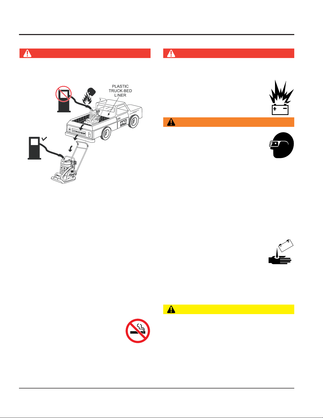
DANGER
DO NOT add fuel to equipment if it is placed inside truck
bed with plastic liner. Possibility exists of explosion or
fire due to static electricity.
FUEL
FUEL
DO NOT start the engine near spilled fuel or combustible
fluids. Diesel fuel is extremely flammable and its vapors
can cause an explosion if ignited.
ALWAYS refuel in a well-ventilated area, away from
sparks and open flames.
ALWAYS use extreme caution when working with
flammable liquids.
DO NOT fill the fuel tank while the engine is running
or hot.
DO NOT overfill tank, since spilled fuel could ignite if it
comes into contact with hot engine parts or sparks from
the ignition system.
Store fuel in appropriate containers, in well-ventilated
areas and away from sparks and flames.
BATTERY SAFETY (ELECTRIC START ONLY)
DANGER
DO NOT drop the battery. There is a possibility that the
battery will explode.
DO NOT expose the battery to open flames,
sparks, cigarettes, etc. The battery contains
combustible gases and liquids. If these
gases and liquids come into contact with a
flame or spark, an explosion could occur.
WARNING
ALWAYS wear safety glasses when
handling the battery to avoid eye irritation.
The battery contains acids that can cause
injury to the eyes and skin.
Use well-insulated gloves when picking up
the battery.
ALWAYS keep the battery charged. If the battery is not
charged, combustible gas will build up.
DO NOT charge battery if frozen. Battery can explode.
When frozen, warm the battery to at least 61°F (16°C).
ALWAYS recharge the battery in a well-ventilated
environment to avoid the risk of a dangerous concentration
of combustible gases.
If the battery liquid (dilute sulfuric acid)
comes into contact with clothing or skin,
rinse skin or clothing immediately with
plenty of water.
If the battery liquid (dilute sulfuric acid) comes into
contact with eyes, rinse eyes immediately with plenty
of water and contact the nearest doctor or hospital to
seek medical attention.
NEVER use fuel as a cleaning agent.
DO NOT smoke around or near the
equipment. Fire or explosion could result
from fuel vapors or if fuel is spilled on a
hot engine.
CAUTION
ALWAYS disconnect the NEGATIVE battery terminal
before performing service on the equipment.
ALWAYS keep battery cables in good working condition.
Repair or replace all worn cables.
PAGE 8 — MVH502DSB/DSB2 PLATE COMPACTOR — OPERATION AND PARTS MANUAL — REV. #5 (03/11/11)
Page 9

TRANSPORTING SAFETY
CAUTION
NEVER allow any person or animal to stand underneath
the equipment while lifting.
NOTICE
Before lifting, make sure that the equipment parts (hook
and vibration insulator) are not damaged and screws are
not loose or missing.
Always make sure crane or lifitng device has been
properly secured to the lifting bail (hook) of the
equipment.
ALWAYS shutdown engine before transporting.
NEVER lift the equipment while the engine is running.
Tighten fuel tank cap securely and close fuel cock to
prevent fuel from spilling.
SAFETY INFORMATION
Use adequate lifting cable (wire or rope) of sufficient
strength.
Use one point suspension hook and lift straight
upwards.
DO NOT lift machine to unnecessary heights.
ALWAYS tie down equipment during transport by
securing the equipment with rope.
ENVIRONMENTAL SAFETY
NOTICE
Dispose of hazardous waste properly.
Examples of potentially hazardous waste
are used motor oil, fuel and fuel filters.
DO NOT use food or plastic containers to dispose of
hazardous waste.
DO NOT pour waste, oil or fuel directly onto the ground,
down a drain or into any water source.
MVH502DSB/DSB2 PLATE COMPACTOR — OPERATION AND PARTS MANUAL — REV. #5 (03/11/11) — PAGE 9
Page 10

OPERATION AND SAFETY DECALS
Figure 1 displays the operation and safety decals as they appear on the reversible plate compactor. Should any of these decals
become damaged or unreadable, contact the Multiquip Parts Department for a replacement set.
Figure 1. Operation and Safety Decals
PAGE 10 — MVH502DSB/DSB2 PLATE COMPACTOR — OPERATION AND PARTS MANUAL — REV. #5 (03/11/11)
Page 11

ELBISREVERBSD205-HVM.1ELBATROTCAPMOCETALP
SNOITACIFICEPS
ecroFlagufirtneC)gk053,6(.sbl000,41
ycneuqerFnoitarbiV)zH76(mpv000,4
deepSgnilevarT )nim/m32ot0(nim/tf5.57ot0
)WxL(eziSetalP )mm055x099(ni7.12x93
htgneLllarevO)mm525,1(ni06
htdiWllarevO)mm055(ni7.12
SPECIFICATIONS
thgieHllarevO)mm
001,1(ni3.34
thgieWgnitarepO)gk015(.sbl2211
esaCnoitarbiVniliOgnitacirbuL)cc000,1(zolf8.33
SNOITACIFICEPSENIGNE.2elbaT
ledoMS18D1ztaH
epyT enignEleseiD,rednilyCelgniS,ekortS-4,delooc-riA
ekortSXeroB
tnemecalpsiDmc766(ni-uc07.04
enignE
tuptuOxaM.M.P.R0063/.P.H0.51
yticapaCknaTleuF)sretil0.7(snollag58.1
leuF2#leseiD
yticapaCliOebuL)sretil7.1(
strauq8.1
.ni43.3X.ni49.3
8xmm001(
).mm5
3
)
dohteMgnitratScirtcelE/eldnaHknarC
hA.xam/.nimyrettaBhA07/54V21
noisnemiD
)HxWxL(
thgieWteNyrD
3.41
.ni00.32X26.91x1
).mm5.485X5.894X5.363(
).gK19(.sbl102
MVH502DSB/DSB2 PLATE COMPACTOR — OPERATION AND PARTS MANUAL — REV. #5 (03/11/11) — PAGE 11
Page 12

DIMENSIONS
Figure 2. MVH502DSB/DSB2 Reversible Plate Compactor Dimensions
SNOISNEMID.3ELBAT
.FERSNOISNEMID
A).mc6.431(.ni35
B).mc16(.ni42
C).mc68(.ni43
D).mc261(.ni8.36
E).mc79(.ni2.83
PAGE 12 — MVH502DSB/DSB2 PLATE COMPACTOR — OPERATION AND PARTS MANUAL — REV. #5 (03/11/11)
Page 13

GENERAL INFORMATION
Plate Compactor
The Mikasa MVH502DSB/DSB2 is a walk behind, reversible
plate compactor designed for the compaction of sand, clay and
asphalt. This plate compactor is a powerful compacting tool
capable of applying a tremendous force in consecutive high
frequency vibrations to a soil surface. Its applications include
soil compacting for road, embankments and reservoirs as well
as backfilling for gas pipelines, water pipelines and cable
installation work.
Vibratory Plates
The vibratory plates of the MVH502DSB/DSB2 produce low
amplitude high frequency vibrations, designed to compact
granular soils.
The resulting vibrations cause forward motion. The engine and
handle are vibration isolated from the vibrating plate. The heavier
the plate, the more compaction force it generates.
Reversible Vibratory Plates
Reversible vibratory plates have two eccentric weights that allow
a smooth transition for forward and reverse travel, plus increased
compaction force as the result of dual weights.
Due to their weight and force, reversible plates are ideal for
semi-cohesive soils.
Frequency/Speed
The compactor's vibrating plate maximum frequency is 4000
vpm (vibrations per minute). The forward and reverse travel speed
of the compactor is approximately 75.5 ft./minute (23 meters/
minute).
Engine
The Mikasa MVH502DSB/DSB2 Plate Compactor is equipped
with a HATZ 1D81S diesel engine.
Controls
Before starting the MVH502DSB/DSB2 Plate Compactor, identify
and understand the function of the controls and components as
indicated in Figure 3.
MVH502DSB/DSB2 PLATE COMPACTOR — OPERATION AND PARTS MANUAL — REV. #5 (03/11/11) — PAGE 13
Page 14
COMPONENTS
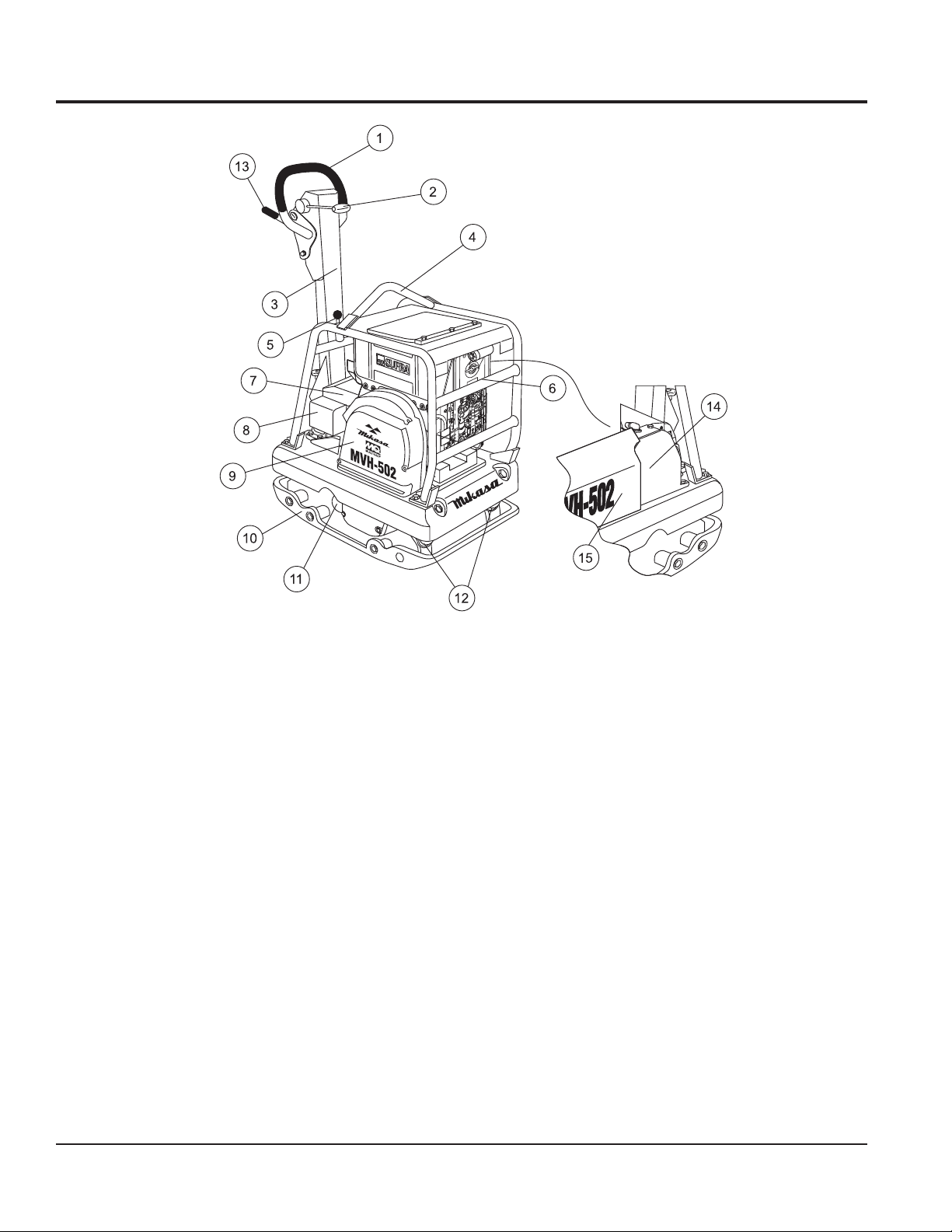
Figure 3. MVH502DSB/DSB2 Reversible Plate Compactor Components
Figure 3 illustrates the location of the major components
for the MVH502DSB/DSB2 Reversible Plate Compactor.
The function of each component is described below:
1. Hand Grip – When operating the compactor use this hand
grip to manuever the compactor.
2. Forward & Reverse Lever –
compactor will move in a forward direction,
backwards, the compactor will move in backwards direction.
Placing the lever in the middle (midway) will cause the
compactor not to move (neutral).
3. Handle Bar – When operating the compactor, this handle
is to be in the downward position. When the compactor is
stored
to be
4. Guard Hook Used to lift the machine with crane or other
lifting device.
5. Stopper Locks the handle in place in the upward postion
for stowing.
6. Engine – This plate compactor uses a HATZ 1D81S diesel
engine. Refer to the owner’s manual for engine information
and related topics.
, move the handle bar to the upright position.
Push
the lever forward, the
pull
the lever
8. Starter Switch Engine starts when key is turned to the
RUN position
9. Belt Cover – Remove this cover to gain access to the
V-belts. NEVER run the compactor without the V-belt cover.
If the V-belt cover is not installed, the possibility exist that
your hand may get caught between the V-belt and clutch,
thus causing serious injury and bodily harm.
10. Base Plate – Designed to compact sand, clay, and asphalt.
11. Vibration Case – Encloses the eccentric, gears and
counter weights.
12. Shock Absorber – Protects plate compactor from damage
by absorbing vibration during operation.
13. Throttle Lever – Controls the speed of the plate compactor.
Place straight vertically to start, push fully counterclockwise
for full trottle and fully clockwise to stop plate compactor.
14. Oil Tank – Fill with proper grade of diesel engine oil.
15. Hydraulic Cylinder – Activated by moving the travel lever.
The cylinder controls the direction of movement by the plate
compactor.
7. Battery Maintenance-free type requiring no electrode
replenishment.
PAGE 14 — MVH502DSB/DSB2 PLATE COMPACTOR — OPERATION AND PARTS MANUAL — REV. #5 (03/11/11)
Page 15

BASIC ENGINE
Figure 4. MVH502DSB/DSB2 Engine Components
ENGINE COMPONENTS
Figure 4 illustrates the location of the major engine
components of the machine. Each component is described
below:
1. Fuel Filler Cap – Remove this cap to add unleaded
gasoline to the fuel tank. Make sure cap is tighten securely.
DO NOT over fill.
4. Muffler – Used to reduce noise and emissions.
WARNING
WARNING
Add fuel to the tank only when the engine is
stopped and has cooled down. In the event
of a fuel spill, DO NOT attempt to start the
engine until the fuel residue has been
completely wiped up and the area
surrounding the engine is dry.
2. Fuel Tank – Capacity is 1.85 gallons (7.0 liters) of #2
diesel fuel.
3. Air Cleaner – Prevents dirt and other debris from entering
the fuel system. Remove wing-nut on top of air filter
cannister to gain access to filter element.
NOTICE
7. Oil Filler Cap/Dipstick – Remove this cap to add oil to the
oil tank. Use dipstick to check oil level.
8. Oil Drain Plug – Unscrew plug to drain oil from engine
crankcase. Dispose of oil in a safe manner.
9. Decompression Lever – Press down before starting
engine. To prevent damage to the engine, DO NOT use for
any other purpose.
10. Fuel Filter – Controls the flow of diesel fuel to the carburetor.
Must be in the ON position when starting and running the
engine.
11. Oil Filter – Filters oil for contaminates. Replace as
necessary.
Engine components can generate extreme
heat. To prevent burns, DO NOT touch these
areas while the engine is running or
immediately after operating. NEVER operate
the engine with the muffler removed.
Operating the engine without an air filter, with a damaged air
filter, or a filter in need of replacement will allow dirt to enter
the engine, causing rapid engine wear.
12. Starting Handle Guide Sleeve – Insert starting handle
into the guide sleeve and turn to crank start engine.
MVH502DSB/DSB2 PLATE COMPACTOR — OPERATION AND PARTS MANUAL — REV. #5 (03/11/11) — PAGE 15
Page 16

INSPECTION
Before Starting
1. Read safety information at the beginning
of manual.
3. If the oil level is low, fill to the edge of the oil filler
hole with the recommended oil type (Table 4).
Maximum oil capacity is 2 quarts (1.9 liters).
2. Familiarize yourself with the operating
and control elements of the machine and
the working environment. This includes obstacles in the
working area, bearing capacity of the ground and the
necessary safety provisions.
3. Check the air filter for dirt and dust. If the air filter is dirty,
replace air filter with a new one as required.
4. Check fastening nuts and bolts for tightness. Loose threads
may cause damage to the machine when vibrating.
5. Understand the geographical features and regulations of
DANGER
the job site.
6. Clean the compactor, removing dirt and dust, particularly,
the bottom of the plate, engine cooling air inlet.
Checking Engine Oil Level
1. Make sure that the machine is situated in a flat
surface so that level measurements will be accurate.
Table 4. Oil Selection Chart
F
C
122
50
104
40
86
30
68
20
10
-14
-22
-40
50
-10
-20
-4
-30
-40
5W/40
032
5W/30
Explosive Fuel
EXPLOSIVE FUEL!
Motor fuels are highly flammable and can
be dangerous if mishandled. DO NOT
smoke while refueling. DO NOT attempt to
refuel if the engine is
OIL: SAE
10W/30
10W
40
30
10W/40
15W/40
20W/20
hot or running
.
2. Pull out the dipstick from the oil tank (Figure 5).
CAUTION
DO NOT overfill oil tank. This could cause oil leaks and
Checking The Fuel
1. Remove the fuel cap located on top of fuel tank.
2. Visually inspect to see if fuel level is low. If fuel is low, replenish
sluggish operation. Clean cap and surrounding area before
opening to prevent dirt from entering tank.
ENGINE OIL
DIPSTICK
HOLDER
3. When refueling, be sure to use a strainer for filtration. DO
Figure 5. Oil Dipstick
with diesel fuel (Figure 6).
NOT top-off fuel. Wipe up any spilled fuel.
Figure 6. Refueling
PAGE 16 — MVH502DSB/DSB2 PLATE COMPACTOR — OPERATION AND PARTS MANUAL — REV. #5 (03/11/11)
Page 17

OPERATION
CAUTION
2. Insert the starter key into the key switch and turn it to
the RUN position (Figure 9).
DO NOT attempt to run the compactor
until the Safety, General, and Inspection
sections have been read and understood.
Adjusting Handle Height
The height of the handle is adjustable for your comfort .
1. Loosen the butterfly screw (Figure 7).
2. Turn the grip clockwise to raise the handle or counterclockwise to lower the handle.
3. When the handle is raised to the desired height, tighten the
butterfly screw.
3. Except for the "
engine status LED's are OFF.
Engine Status LED's Definitions
■
"
Happy Face
engine and associated components are functioning correctly.
Figure 9. Starter Switch
Happy Face"
" status LED. This LED when lit indicates that the
status LED, verify that all other
Figure 7. Handle Adjustment
STARTING THE ENGINE
Electric Start
1. Move the throttle lever to the START position by opening it
to about 20 degrees (Figure 8 ).
Figure 8. Throttle Lever (Start Position)
■
"
Battery
battery charging system is not working correctly. If this LED
remains ON, stop the engine and correct the problem.
■
"
Oil Pressure
the Oil pressure is low. If this LED remains ON, stop the engine
and correct the problem.
■
"
Water Temperature
that the Water temperature is too high. If this LED remains ON,
stop the engine and correct the problem.
■
"
Air Filter
filter is dirty and is not functioning correctly. If this LED remains
ON, stop the engine and correct the problem.
4. Turn the starter key further to the right to the START
5. If the engine fails to start, do not continue to rotate
" status LED. This LED when lit indicates that the
" status LED. This LED when lit indicates that
" status LED. This LED when lit indicates
" status LED. This LED when lit indicates that the air
position to start the engine. Buzzer stops sounding
and the engine starts.
the starter key for more than 5 seconds. Return the
key to the RUN position and wait 10 seconds before
starting again.
CAUTION
While the engine is running, never try to turn the starter
key to the START position.
MVH502DSB/DSB2 PLATE COMPACTOR — OPERATION AND PARTS MANUAL — REV. #5 (03/11/11) — PAGE 17
Page 18

OPERATION
Crank Handle Start
1. Move the throttle lever to the START position by opening it
to about 20 degrees (Figure 8).
2. Pull up decompression lever (Figure 10) to position
1 and release.
Figure 10. Decompression Lever
3. Insert the crank handle into the engine’s starting
handle guide sleeve (Figure 11).
TRAVELING
CAUTION
Make sure to follow all safety rules referenced in the safety
section of this manual before operating compactor. Keep
work area clear of debris and other objects that could
cause damage to the compactor or bodily injury.
1. Grasp the compactor's hand grip (Figure 13), and move the
engine throttle lever (Figure 13) quickly to the
2. With the throttle lever in the fast position, the engine speed
should be around 2,300 RPM, therefore engaging the centrifugal clutch.
fast
position.
Figure 11. Crank Handle Guide Sleeve
4. When turning the crank handle, observe the correct
operating position (Figure 12).
NOTICE
ALWAYS
hesitation, because increasing the engine speed slowly
causes the clutch to slip.
3. To make the compactor move in the forward direction push
the travel lever ( Figure 14) forward.
Figure 12. Starting Handle Operating Position
5. Grasp the crank handle firmly in both hands and turn
counterclockwise at increasing speed. Five turns of
the starting handle are needed to build up enough
compression to start the engine.
6. Once the engine starts, stop cranking and remove
the starting handle from the guide sleeve.
CAUTION
There is a risk of injury from the rotating crank handle. When
using the crank handle, keep the body clear of the handle to
avoid being struck. If the engine backfires because the handle
was not turned firmly enough release the starting handle
immediately and stop the engine.
4. To make the compactor move in the reverse direction pull the
travel lever ( Figure 13) backwards.
5. Firmly gasp the compactor's hand grip, the compactor will
begin moving in the desired position when the direction lever
has been placed in the desired position.
Figure 13. Throttle Lever ((Fast)
move the throttle lever quickly without
Figure 14. Direction Lever
PAGE 18 — MVH502DSB/DSB2 PLATE COMPACTOR — OPERATION AND PARTS MANUAL — REV. #5 (03/11/11)
Page 19

OPERATION
6. Slowly walk behind the compactor and be on the lookout for
any large objects or foreign matter that might cause damage
to the compactor or bodily injury.
7. If travel lever is placed in the neutral position, the machine will
vibrate in place.
8. To move the compactor laterally, hold the hand grip firmly and
swing compactor. Do not swing compactor while gripping the
travel lever.
STOPPING
1. Return the throttle lever to the START position (Figure 9).
Allow the machine to cool down for 2 to 3 minutes.
2. Turn the throttle lever to the STOP position (Figure 15) to
stop the engine. In a motor start, return the key switch to the
STOP position (Figure 16) as soon as the engine stops.
STOWING THE HANDLE
1. Push up the handle (Figure 17).
2. Pull the stopper grip upward into the hole of the guard
frame to lock the handle.
Figure 15. Throttle Lever (Stop)
Figure 16. Starter Switch (STOP)
Emergency Shutdown
1. Move the throttle lever quickly to the
and place the engine
position.
IGNITION
STOP
switch in the
position,
OFF
Figure 17. Stowing the Handle
LIFTING
1. Use a crane or lift to load and unload the machine. A
skilled crane operator is required to perform the job.
2. When lifting the machine, check for any damaged or
loose bolts, lifting hooks, and shock mounts.
3. Check any damaged or loose bolts in the guard frame to
avoid machine sliding off.
4. Make sure that the machine is shut off before machine is
lifted.
5. Use reliable cable for lifting.
6. Always lift the machine vertically and keep the
machine away from workers and animals.
7. Do not lift the machine higher than the required
height.
TRANSPORTING
1. Always make sure that the machine is shut off while
being transported.
2. Check that the fuel cap is properly closed and
tightened.
3. When traveling long distances or on rugged terrain,
drain the fuel of the machine before transporting.
4. Tie down the machine securely on the
transportation so that it will not move or topple over.
MVH502DSB/DSB2 PLATE COMPACTOR — OPERATION AND PARTS MANUAL — REV. #5 (03/11/11) — PAGE 19
Page 20

MAINTENANCE
CAUTION
Inspection and other services should
always
be carried
out on hard and level ground with the engine shutdown.
Inspection and Maintenance Service Tables.
1. To make sure your plate compactor is always in good
working condition before using, carry out the maintenance
inspection in accordance with Tables 5 through 7.
BSD205-HVM.5ELBATNOITCEPSNIENIHCAM
METI
gnissiMroesooL
swercS
straPdegamaD
gnillortnoCfonoitcnuF
traPmetsyS
FOSRUOH
NOITAREPO
sruoh8yrevE
)yadyreve(
sruoh8yrevE
)yadyreve(
sruoh8yrevE
)yadyreve(
SKRAMER
CAUTION
Fuel piping and connections should be replaced every 2
years.
BSD205-HVM.6ELBATKCEHCENIGNE
METINOITAREPOFOSRUOH
kaeLleuFroliO)yadyreve(sruoh8yrevE
gninetsaFfossenthgiT
sdaerhT
d
nakcehCliOenignE
tnemhsinelpeR
gnE
tnemecalpeRliOeni
gninaelCretliFriAsruoh001yrevE
)level
sruoh001
)yadyreve(sruoh8yrevE
)yadyreve(sruoh8yrevE
mumixamdeificepsothsinelpeR(
ot05yrevenehtsruoh52tsrifretfA
kaeLmetsySciluardyHsruoh001yrevE02egapeeS
tarbiVsruoh001yrevE22egapeeS
kcehCliOro
liOrotarbiV
tnemecalpeR
sruoh003yrevE22egapeeS
Daily Service
Check for leakage of fuel or oil.
Check for loose screws including tightness. See Table 7
below (tightening torque ), for retightening:
kcehCliOciluardyHsruoh001yrevE22eg
liOciluardyH
tnemecalpeR
kcehC)hctulc(tleb-Vsruoh002
kcehCyrettaBsruoh001yrevE32egapeeS
002retfatsriF
yreveneht,sruoh
sruoh000,1
yrevE12egapeeS
apeeS
22egapeeS
T4 07 051 003 005 057 001,1 004,1 000,2
T8-6 001 052 005 008 003,1 000,2 007,2 008,3
T11 051 004 008 002,1 000,2 009,2 002,4 006,5
* 001
CAUTION
These inspection intervals are for operation under normal
conditions. Adjust your inspection intervals based on the
number hours plate compactor is in use, and particular
working conditions.
Remove soil and clean the bottom of compaction plate.
Check hydraulic pump, piping and hose for any leakage. A
loosened hydraulic hose can be a cause for leakage. Check
hydraulic hose connections with wrench applied for
tightness.
nigneetarapeseeS
.7ELBAT
mm6 mm8 mm01 mm21 mm41 mm61 mm81 mm02
lairetaM
~003
053
~056
007
)munimulafositrap-retnuocesacnI(*
)dednahthgirllaeraenihcamsihthtiwesunisdaerhT(
kramsilairetamfoytilauqdnalairetaM
.kcehcenignenosliatedroflauname
retemaiD)mc/gk.ni(EUQROTGNINETHGIT
.wercsdna,tlobhcaenode
Check engine oil.
PAGE 20 — MVH502DSB/DSB2 PLATE COMPACTOR — OPERATION AND PARTS MANUAL — REV. #5 (03/11/11)
Page 21

Engine Oil Replacement:
1. Replace engine oil, first in 25 hours of operation and every
50 to 100 hours afterwards.
2. Oil may be drained more easily when it is warm after
operation (For more details, see separate engine Owner's
Manual).
Air Filter
1. The air filter element should be cleaned because a clogged
air cleaner can cause poor engine starting, lack of power
and shorten engine life substantially.
AIR FILTER
CANNISTER
CLEAN USING
COMPRESSED
DRY AIR
Replacing the V-belt
Remove the belt cover. Engage an offset wrench (19 mm) or the
like to vibrator pulley (lower) fastening bolt. Engage waste cloth
or the like at midway of V-belt on the left side and while pulling it
back strongly, rotate the offset wrench clockwise so that the V-
AIR FILTER
WING NUT
CARTRIDGE
Figure 18. Engine Air Filter
2. To clean or replace air filter loosen the wing nut on the air
filter housing (Figure 18), remove the cover and take out air
filter cartridge. If only cleaning of the air filter is desired blow
through the air filter cartridge from the inside, moving a jet of
dry compressed air up and down until all dust is removed.
WARNING
belt will come off.
Reinstalling the V-belt
Engage V-belt to lower vibrator pulley and push the V-belt to left
side of upper clutch and, in the same manner as in removal,
rotate offset wrench clockwise so that the V-belt goes back on.
Checking Clutch
Check the clutch simultaneously with V-belt checking. With belt
cover removed, check outer drum of the clutch for seizure and
"V" groove for wear or damage with your eyes. Clean the "V"
NEVER attempt to check the V-belt with the engine running. Severe injury can occur if your hand (Figure 5) gets
caught between the V-belt and the clutch. Always use
groove as necessary. Wear of lining or shoe should be checked
with running check. If the shoe is worn, power transmission
becomes deficient and slipping will result.
safety gloves.
Replacing Clutch
CLUTCH
PULLEY
Remove V-belt. Remove bolt at engine power output by giving a
shock to an engaged wrench (tapping with hammer or the like)
and rotating bolt counterclockwise. Remove clutch with a pulley
extractor. To reinstall, reverse the procedure.
MAINTENANCE
Figure 20. V-Belt Check
VIBRATOR
PULLEY
Figure 19. V-Belt Hazard
WARNING
Whenever the compactor's vibration becomes weak or lost
during normal operation regardless of operation hours, check
Checking and Replacing the V-Belt and Clutch
the V-belt and clutch immediately.
1. After 200 hours of operation, remove the belt cover to check
the V-belt tension (Figure 20). Tension is proper if the belt
bends about 10 mm when depressed strongly with finger
between shafts. Loose or worn V-belts reduces power
transmission efficiency, causing weak compaction and
reduces the life of the belt itself.
MVH502DSB/DSB2 PLATE COMPACTOR — OPERATION AND PARTS MANUAL — REV. #5 (03/11/11) — PAGE 21
Page 22

MAINTENANCE
Vibrator Oil Level Check
NOTICE
Always clean the area around the vibrator oil level check hole
before removing oil check plug. This will prevent dirt and
debris from entering the system.
1. In every 100 hours of operation, with the machine positioned
horizontally, remove vibrator oil level check plug
(Figure 21) off vibrator (19 mm wrench) and see if oil is up to
filler port. Be sure to clean area around check hole to prevent
dirt and dust from entering.
2. In every 300 hours of operation, replace oil (capacity 1,500
cc). For draining oil through level check hole, have the
machine inclined with a sleeper or the like placed under the
compaction plate on opposite side.
* Use engine oil 10W-30 for this lubrication.
Replacing Hydraulic Oil
1. Remove the drain plug (Figure 22) at the bottom of the oil
tank with a 6 mm hex wrench and drain the hydraulic oil.
2. Clean the filter with light oil.
3. Reinstall the drain plug to the oil tank. Apply seal tape or
Roctite #575 to thread portion.
4. Fill tank with hydraulic oil. (Capacity: About 2,500 cc). Use
Shell Tellus Oil #46
5. After filling tank, temporarily install cover. Loosen bleeder
plug located at the top of the cylinders on side of vibrator
(Figure 23). Air remaining in the circuit will be forced out of
the bleeder plug.
6. Tighten the breather plug. Check oil level in the tank again.
7. Install the cover of oil tank. Coat packing with liquid packing
such as Threebond #1215. Use loctite #242 for mounting
screw.
or equivalent.
Figure 21. Vibrator Oil Maintenance
Hydraulic Oil
1. Check hydraulic oil in every 100 hours of operation. With
handle bar positioned vertically (storage position), remove
breather plug (Figure 23) off the top of hydraulic pump and
check for proper oil level.
2. Replace hydraulic oil after first 200 hours and in every 1,000
hours of operation.
Figure 22. Hydraulic Oil Maintenance
CAUTION
Make sure hydraulic oil i is at a normal safe operating level.
DO NOT over fill. Over filling (excessive oil) will cause excess
oil to blow out of breather plug.
Figure 23. Bleeder Plug
PAGE 22 — MVH502DSB/DSB2 PLATE COMPACTOR — OPERATION AND PARTS MANUAL — REV. #5 (03/11/11)
Page 23

MAINTENANCE
BATTERY MAINTENANCE
1. Check the battery terminals periodically to ensure
that they are in good condition.
2. Use wire brush or sand paper to clean the battery
terminals.
3. Check battery for cracks or any other damage. If white
pattern appears inside the battery or paste has
accumulated at the bottom, replace the battery.
4.. If the machine will not be in operation for a long
period of time, store in cool dry place and check the
battery charge level every month to maintain the
performance of the battery.
BATTERY CABLE CONNECTION
1. Take off the battery cover by removing the M6 nuts
(Figure 24).
2. When removing cable, disconnect the ground side (normally
negative) first (Figure 24).
3. When installing cable connect the ground side (normally
negative) last.
CAUTION
Wear
safety glasses
rubber gloves
and
or
face mask, protective clothes
when working with battery.
,
Figure 24. Battery Maintenance
MVH502DSB/DSB2 PLATE COMPACTOR — OPERATION AND PARTS MANUAL — REV. #5 (03/11/11) — PAGE 23
Page 24

TROUBLESHOOTING
Practically all breakdowns can be prevented by proper
handling and maintenance inspections, but in the event of a
breakdown, please take a remedial action following the
diagnosis based on the Troubleshooting (Table 8) information
shown below. If the problem cannot be remedied, please
leave the unit just as it is and consult our company's business
office or service plant.
MOTPMYSMELBORPELBISSOPNOITULOS
?noitisop"POTS"nisirevellortnocdeepS .noitisop"TRATS"otrevellortnocdeepsteS
itcejnignihcaerleufoN .metsysleuferitnekcehC.leufddA
?pmupleufevitcefeD.pmupleufecalpeR
F .knatnaelcdnaretlifleufecalpeR
sitratsrotratstonlliwenignE
a,deyaled
.revodenrut
ebnacenignehguohtl
?deggolcretlifleu
?enilylppusleufytluaF .enilleufriaperroecalpeR
?wolootnoisserpmoC
?wolooterusserpliO .erusserplioenignekcehC
?pmupno
?yltcerrocgnikrowtonrotcejnileuF
ilerutarepmetgnitratswoL
?dedeecxetim
GNITOOHSELBUORTENIGNE.8ELBAT
A.sevlavdnarednilyc,notsipkcehC
.launamriaperenignerepriaper
occanirotcejniecalperroriapeR
.launamriaperenigne
.ytisocsivlioreporp
rotsujd
htiwecnadr
dnasnoitcurtsnignitratsdlochtiwylpmoC
hwkcehC
otecnatsiseretauqedanisahsetarapesleuF
twoltA
.tratston
.ffodehctiwssiretrats
.noitarepolamron
.deeps
lliwenigneserutarepme
elelttorhT .noitisopNURotrevelelttorhtnoitisopeR
sanoosspotstubserifenignE
gnirudflestiybspotsenignE
euF.retlifleufecalpeR
dnatuptuo,rewopenignewoL
ocdeepS
?serutarepmetwol
?kcihtootlioenignE
?noitisopPOTSnirev
?dekcolbretlifleuF.retlifleufecalpeR
?dekcolbylppusleuF .metsysleuferitneehtkcehC
?ytpmeknatleuF.leufddA
?dekcolbretlifl
?ytpmeknatleuF.retlifleufecalpeR
?deggolcretlifleuF.re
?etauqedanisignitnevknatleuF .detnevyletauqedasiknattahterusnE
niniamertonseodrevellortn
?noitisopdetceles
?llufootlevellioenignE.levellioenignetcerro
C
mocehtniardroenigne
.tnemnorivneretniwrof
tlifleufecalpeR
segremeleuf)dibrutton(raelcrehte
.)pmupnoitcejnimorfhcated(enilleufehtmorf
ehtpumraw,detarapesrodibrutsileufehtfI
ylppusleufetelp
.leufleseidedargretniwhtiwleufeR.metsys
liofoepyttcerrochtiwesacknarcenignellifeR
.noitcaevitcerrocroflaunamenigneeeS
?dekcolbretlifriA .retlifriaecalperronaelC
dnatuptuorewopenignewoL
.ekomstsuahxekcalb,deepswol
lcevlavtcerrocnI .noitacificepsenignerepsevlavtsujdA
?secnarae
?rotcejnitanoitcnuflaM.launamenigneeeS
PAGE 24 — MVH502DSB/DSB2 PLATE COMPACTOR — OPERATION AND PARTS MANUAL — REV. #5 (03/11/11)
Page 25

TROUBLESHOOTING
Practically all breakdowns can be prevented by proper
handling and maintenance inspections, but in the event of a
breakdown, please take a remedial action following the
diagnosis based on the Troubleshooting (Table 9) information
shown below. If the problem cannot be remedied, please
leave the unit just as it is and consult our company's business
office or service plant.
MOTPMYSESUACELBISSOPNOITULOS
?spilshctulC.hctulcecalperrotsujdA
V.tleb-VecalperrotsujdA
.kaewnoitarbivdnawoldeepslevarT
?spilstleb-
?rotarbivniliOevissecxE..leveltcerrocotlliF
?slanretnirotarbivnielbuorT
?.et
sysgnisrever
?tcerrocnideepsenignE .MPRtcerrocotdeepsenigneteS
levartrofrofliociluardyhninoitareA
?.evitareponimetsysgnisreverlevarT.metsyslevarteritnekcehC
ROTCAPMOCGNITOOHSELBUORT.9ELBAT
ofylbmessarotarbivkcehC
.strap
ronrowynar
evitcefedynaecalper,strapevitcefed
)gulpdeelB(.liociluardyhniriaegruP
?tcerrocnoitallatsnirevelgnisreveR .revelgnisreverfonoitallatsninaelC
?esohlioevitcefedronekorB.esohlioe
?metsysgnis
?hsarthtiwdeggolcevlavrotceleS.evlavrotcelesnaelC
?eruliafgniraeb
?spi
retpadaroyektahstupnipmuP
?eruliafgniraebnotsiprednilyC
levartrofrofliociluardyhninoitareA
yaw-yek
elbanut
.noitceridhctiwsot
ubdrawkcabrodrawrofslevarT
.esreverrodrawrofnilevarttonseoD
ecnatsisergnitareporevelgnisreveR
.taerg
?.etsysgnisrever
revernilioevissecxE..leveltcerrocotlliF
notsiprednilyC
lsrodegagne-sidtleb-V .ecalperrotsujda,tleb-VegagnE
?spilshctulC .yrassecenfiecalper,hctulctsujdA
?degamad
issecxE.leveltcerrocotlliF
?liociluardyhev
calpeR
)gulpdeelB(.liociluardyhniriaegruP
.gnikcapHSUtaegakael
.gnikcapHSUtaegakael
rofrednilycnigniraebnotsipkcehC
yaw-yekretpadaroyektahstupniecalpeR
rofr
ednilycnigniraebnotsipkcehC
MVH502DSB/DSB2 PLATE COMPACTOR — OPERATION AND PARTS MANUAL — REV. #5 (03/11/11) — PAGE 25
Page 26

EXPLANATION OF CODE IN REMARKS COLUMN
The following section explains the different symbols and
remarks used in the Parts section of this manual. Use the
help numbers found on the back page of the manual if there
are any questions.
NOTICE
The contents and part numbers listed in the parts
section are subject to change without notice. Multiquip
does not guarantee the availability of the parts listed.
SAMPLE PARTS LIST
NO. PART NO. PART NAME QTY. REMARKS
1 12345 BOLT ......................1 .....INCLUDES ITEMS W/%
2% WASHER, 1/4 IN. ...........NOT SOLD SEPARATELY
2% 12347 WASHER, 3/8 IN. ...1 .....MQ-45T ONLY
3 12348 HOSE ..................A/R ...MAKE LOCALLY
4 12349 BEARING ..............1 .....S/N 2345B AND ABOVE
NO. Column
Unique Symbols — All items with same unique
symbol
QTY. Column
Numbers Used — Item quantity can be indicated by a
number, a blank entry, or A/R.
A/R (As Required) is generally used for hoses or other
parts that are sold in bulk and cut to length.
A blank entry generally indicates that the item is not sold
separately. Other entries will be clarified in the “Remarks”
Column.
REMARKS Column
Some of the most common notes found in the “Remarks”
Column are listed below. Other additional notes needed
to describe the item can also be shown.
Assembly/Kit — All items on the parts list with the
same unique symbol will be included when this item is
purchased.
Indicated by:
“INCLUDES ITEMS W/(unique symbol)”
(@, #, +, %, or >) in the number column belong to the
same assembly or kit, which is indicated by a note in the
“Remarks” column.
Duplicate Item Numbers — Duplicate numbers indicate
multiple part numbers, which are in effect for the same
general item, such as different size saw blade guards in
use or a part that has been updated on newer versions
of the same machine.
NOTICE
When ordering a part that has more than one item
number listed, check the remarks column for help in
determining the proper part to order.
PART NO. Column
Numbers Used — Part numbers can be indicated by a
number, a blank entry, or TBD.
TBD (To Be Determined) is generally used to show a
part that has not been assigned a formal part number
at the time of publication.
A blank entry generally indicates that the item is not sold
separately or is not sold by Multiquip. Other entries will
be clarified in the “Remarks” Column.
Serial Number Break — Used to list an effective serial
number range where a particular part is used.
Indicated by:
“S/N XXXXX AND BELOW”
“S/N XXXX AND ABOVE”
“S/N XXXX TO S/N XXX”
Specific Model Number Use — Indicates that the part
is used only with the specific model number or model
number variant listed. It can also be used to show a
part is NOT used on a specific model or model number
variant.
Indicated by:
“XXXXX ONLY”
“NOT USED ON XXXX”
“Make/Obtain Locally” — Indicates that the part can
be purchased at any hardware shop or made out of
available items. Examples include battery cables, shims,
and certain washers and nuts.
“Not Sold Separately” — Indicates that an item cannot
be purchased as a separate item and is either part of an
assembly/kit that can be purchased, or is not available
for sale through Multiquip.
PAGE 26 — MVH502DSB/DSB2 PLATE COMPACTOR — OPERATION AND PARTS MANUAL — REV. #5 (03/11/11)
Page 27

MQ MIKASA MVH502DSB/DSB2 REVERSIBLE PLATE
COMPACTOR W/HATZ 1D81S DIESEL ENGINE
1 to 3 Units
Qty. P/N Description
6 .......... 070200453 ........... V-BELT-45 GREEN
3 .......... 456499280 ........... FILTER, HYDRAULIC OIL TANK
1 .......... 457333760 ........... THROTTLE CABLE ASSY.
6 .......... 01480000 ............. OIL FILTER, ENGINE
1 .......... 50397300 ............. SEIVE, FUEL TANK
6 .......... 50478800 ............. FUEL FILTER
1 .......... 50385800 ............. CAP, FUEL TANK
6 .......... 01493000 ............. AIR FILTER
3 .......... 50345300 ............. KEY, IGNITION
NOTICE
Drawings and Parts Lists of Hatz1D81S Engine is
only for Tier 1 engines (MVH502DSB units). If you
have a Tier 2 engine (MVH502DSB2 units), contact
Hatz engine manufacturer for parts information.
SUGGESTED SPARE PARTS
MVH502DSB/DSB2 PLATE COMPACTOR — OPERATION AND PARTS MANUAL — REV. #5 (03/11/11) — PAGE 27
Page 28

DECAL PLACEMENT
PAGE 28 — MVH502DSB/DSB2 PLATE COMPACTOR — OPERATION AND PARTS MANUAL — REV. #5 (03/11/11)
Page 29

DECAL PLACEMENT
NO. PART NO. PART NAME QTY. REMARKS
1 920204580 FULL THROTTLE DECAL 1 NPA-458
2 920202220 FORWARD/REVERSE DECAL 1 NPA-222
3 920206370 OPERATIONAL CAUTION DECAL 1 NPA-538
4 920203330 HEARING PROTECTION DECAL .............. 1......... NPA-333
5 920201580 MULTIQUIP LOGO DECAL 1
6 920103670 OIL LEVEL INDICATOR DECAL 1 NPA-367
7 920207480 SHELL OIL #46DECAL 1 NPA-748
8 920205000 MVH-502 DECAL 1
9 920203260 OIL TANK DECAL 1 NPA-326
MVH502DSB/DSB2 PLATE COMPACTOR — OPERATION AND PARTS MANUAL — REV. #5 (03/11/11) — PAGE 29
Page 30

VIBRATING PLATE ASSY.
PAGE 30 — MVH502DSB/DSB2 PLATE COMPACTOR — OPERATION AND PARTS MANUAL — REV. #5 (03/11/11)
Page 31

VIBRATING PLATE ASSY.
NO. PART NO. PART NAME QTY. REMARKS
1 457112370 VIBRATING PLATE 550B 1
2 953405840 DRAIN PLUG M 18 (R) 1
3 953402930 COPPER PACKING 19X30X1 1
4 953400270 PLUG 1/4X14 10L 1
5 953405260 PACKING 1/4 (CU) 1
6 939010070 SHOCK ABSORBER 100 4
7 020316130 NUT M16 4
8 030216400 WASHER, LOCK M16 4
9 001221655 BOLT 16X75 T 4
10 030216400 WASHER, LOCK M16 4
11 001201830 BOLT 18X30 8
12 030218460 WASHER, LOCK M18 8
21 456210690 EXTENSION PLATE .................................... 2 ...... OPTION
22 001221850 BOLT 18X50 T .............................................. 8 ...... OPTION
23 457215350 BELT COVER GUARD .................................. 1 ...... G1185-
24 457454090 CUSHION, BELT COVER GUARD ............... 1 ...... G1185-
MVH502DSB/DSB2 PLATE COMPACTOR — OPERATION AND PARTS MANUAL — REV. #5 (03/11/11) — PAGE 31
Page 32

BASE AND ENGINE ASSY.
PAGE 32 — MVH502DSB/DSB2 PLATE COMPACTOR — OPERATION AND PARTS MANUAL — REV. #5 (03/11/11)
Page 33

BASE AND ENGINE ASSY.
NO. PART NO. PART NAME QTY. REMARKS
2 457116080 BASE 1
3 457333670 ENGINE PLATE (F) 1
4 457333680 ENGINE PLATE (R) 1
5 001221252 BOLT 12X60 T 4
6 030212300 WASHER, LOCK M12 4
7 031112230 WASHER, FLAT M12 4
8 918400600 ENGINE AY 1D81S 1
9 001221225 BOLT 12X25 T 4
10 030212300 WASHER, LOCK M12 4
11 457336260 STUB SHAFT (1D81) 1
11 457339570 STUB SHAFT (1D- 81) ................................. 1 ...... G1195-
12 001220830 BOLT 8X30 T 4
12 001221025 BOLT 10X25 T .............................................. 1 ...... G1195-
13 030208200 WASHER, LOCK M8 4
14 457114280 BELT COVER (IN) 1
16 001521040 SOCKET HEAD BOLT 10X40 T 4
17 457114290 BELT COVER (OUT) 1
18 001521055 SOCKET HEAD BOLT 10X75 T 1
19 001521058 SOCKET HEAD BOLT 10X90 T 2
20 457445880 DUST PACKING 1
21 457112431 DUST COVER 1
22 457335980 HOLDER, DUST COVER 2
23 001220615 BOLT 6X15 T 4
24 030206150 WASHER, LOCK M6 4
25 031106100 WASHER, FLAT M6 4
26 457336370 CLUTCH AY B2- 175 1
27 951400360 KEY 7X7X49 1
28 952401390 WASHER 11X40X6 1
29 001221035 BOLT 10X35 T 1
30 030210250 WASHER, LOCK M10 1
31 070200453 V- BELT - 45 GREEN 2
32 457112440 BELT COVER (LOWER- IN) 1
MVH502DSB/DSB2 PLATE COMPACTOR — OPERATION AND PARTS MANUAL — REV. #5 (03/11/11) — PAGE 33
Page 34

BASE AND ENGINE ASSY.
PAGE 34 — MVH502DSB/DSB2 PLATE COMPACTOR — OPERATION AND PARTS MANUAL — REV. #5 (03/11/11)
Page 35

BASE AND ENGINE ASSY.
NO. PART NO. PART NAME QTY. REMARKS
33 001221025 BOLT 10X25 T 4
34 030210250 WASHER, LOCK M10 4
35 031110160 WASHER, FLAT M10 4
36 457212400 BELT COVER (LOWER- OUT) 1
37 001220835 BOLT 8X35 T 4
38 030208200 WASHER, LOCK M8 4
39 031108160 WASHER, FLAT M8 4
40 457332401 PULLEY B2- 125 / 131- 68 1
41 456437920 WASHER, PULLEY 1
42 001221235 BOLT 12X35 T 1
43 030212300 WASHER, LOCK M12 1
44 457333710 DRAIN GUIDE 1
45 001221015 BOLT 10X15 T 1
46 030210250 WASHER, LOCK M10 1
48 457116020 GUARD FRAME 1
49 001221430 BOLT 14X30 T 4
50 030214350 WASHER, LOCK M14 4
52 452312020 STOPPER, CRANK HANDLE 2
54 001220812 BOLT 8X12 T 4
55 030208200 WASHER, LOCK M8 4
56 457452690 RUBBER COVER, GUARD FRAME 1
57 457452710 PLATE, COVER 1
58 001220825 BOLT 8X25 T 4
59 031108160 WASHER, FLAT M8 4
60 457336380 FAN 1
61 001220820 BOLT 8X20 T 6
62 030208200 WASHER, LOCK M8 6
63 001521052 SOCKET HEAD BOLT 10X60 T 1
MVH502DSB/DSB2 PLATE COMPACTOR — OPERATION AND PARTS MANUAL — REV. #5 (03/11/11) — PAGE 35
Page 36

VIBRATOR ASSY.
PAGE 36 — MVH502DSB/DSB2 PLATE COMPACTOR — OPERATION AND PARTS MANUAL — REV. #5 (03/11/11)
Page 37

VIBRATOR ASSY.
NO. PART NO. PART NAME QTY. REMARKS
1 457112460 VIBRATING CASE 1
2 001221470 BOLT 14X150 T 6
3 001221450 BOLT 14X50 T 4
4 030214350 WASHER, LOCK M14 10
5 047920060 ROLLER BEARING NJ310MC4 4
6 457212410 ROTARY SHAFT, DRIVE 1
7 457445831 ADAPTER, PUMP ( 30L ) 1
8 951405370 KEY 15X10X39 RR 1
9 456327150 GEAR, DRIVE 1
10 080200550 STOP RING S- 55 2
11 060105030 OIL SEAL SB- 50729 1
12 951404970 KEY 12X8X30 R 1
13 457333720 ECCENTRIC ROTOR 4
14 009120301 SOCKET HEAD BOLT 16X40 T 2
15 456337670 ROTARY SHAFT, DRIVEN 1
16 009120302 SOCKET HEAD BOLT 16X30 T 2
17 456337380 PISTON ROD 1
18 456010010 KNOCK PIN 10X70 1
19 456327120 GEAR, DRIVEN 1
20 040006911 BEARING 6911 2
21 455435020 COLLAR 17X30X3 2
22 456451280 SPRING 3.2- 26.3- 102L 1
24 080100300 STOP RING R- 30 1
25 042506000 BEARING 6000ZZSG 2
MVH502DSB/DSB2 PLATE COMPACTOR — OPERATION AND PARTS MANUAL — REV. #5 (03/11/11) — PAGE 37
Page 38

VIBRATOR ASSY.
PAGE 38 — MVH502DSB/DSB2 PLATE COMPACTOR — OPERATION AND PARTS MANUAL — REV. #5 (03/11/11)
Page 39

VIBRATOR ASSY.
NO. PART NO. PART NAME QTY. REMARKS
26 080200100 STOP RING S- 10 1
27 455435051 PISTON, 22.4D 1
28 455010070 PACKING USH- 22.4X30X5 1
29 080100260 STOP RING R-26 1
30 456327130 BEARING COVER 1
31 456210646 CYLINDER ( R) ( AC) 1
32 954405550 CLAMP 15 R 1
33 050101050 O- RING G- 105 3
34 001221025 BOLT 10X25 T 7
35 030210250 WASHER, LOCK M10 12
36 001220812 BOLT 8X12 T 1
37 953404600 COPPER PACKING 8X16X2 1
38 455010020 ELBOW 45 15- 0404 1
39 031110160 WASHER, FLAT M10 7
40 457332430 FLANGE, PUMP 1
41 457010010 PUMP FBL 1
42 457445840 BRACKET, CLAMP 1
43 457212420 PUMP COVER 1
44 001221035 BOLT 10X35 T 2
45 001221030 BOLT 10X30 T 5
46 952405540 WASHER 10.5- 22- 3 2
47 030210250 WASHER, LOCK M10 2
48 954010140 ELBOW 90 UES90G02G02 1
49 954001780 ELBOW 45 PF3/8- PF1/4 1
50 952405470 SHIM 90X110X0.5 2
MVH502DSB/DSB2 PLATE COMPACTOR — OPERATION AND PARTS MANUAL — REV. #5 (03/11/11) — PAGE 39
Page 40

HYDRAULIC SYSTEM ASSY.
PAGE 40 — MVH502DSB/DSB2 PLATE COMPACTOR — OPERATION AND PARTS MANUAL — REV. #5 (03/11/11)
Page 41

HYDRAULIC SYSTEM ASSY.
NO. PART NO. PART NAME QTY. REMARKS
51 456337780 SELECTOR VALVE 1
52 001220615 BOLT 6X15 T 4
53 030206150 WASHER, LOCK M6 4
54 031106100 WASHER, FLAT M6 4
55 457446180 OIL HOSE 1370L 1
56 457446190 OIL HOSE 1150L 1
57 457451750 OIL HOSE IB105- L820 1
58 457446210 OIL HOSE 1100L 1
59 955404271 SPIRAL TUBE, SR15- 850L 2
60 954403060 CLAMP HC- 40 1
61 954403070 CLAMP SPACER HC- 40 1
62 001220612 BOLT 6X12 T 2
63 030206150 WASHER, LOCK M6 2
64 506010070 CLAMP TC-150 1
65 954001160 ELBOW 90 PT1/4- PF1/4 4
66 457112910 OIL TANK 1
67 001221030 BOLT 10X30 T 2
68 030210250 WASHER, LOCK M10 3
69 031110160 WASHER, FLAT M10 3
70 505015380 PLUG PT 1/4 1
71 457332440 COVER, OIL TANK 1
72 457445870 PACKING, OIL TANK 1
73 001220820 BOLT 8X20 T 2
74 030208200 WASHER, LOCK M8 2
75 031108160 WASHER, FLAT M8 2
76 456449280 FILTER OIL TANK 1
77 457445861 JOINT 80L 1
79 506010060 CLAMP TC- 350 2
80 457448680 BREATHER PLUG 1
81 05340020 PACKING 19302 2
82 457448380 BREATHER CAP 1
83 457451740 BREATHER JOINT 1
84 551010630 ELBOW PT1/4- PF3/8 1034- 06 1
86 953405260 PACKING 1/4 ( CU ) 3
87 605010360 BUSHING 3/8X1/4 1
88 457446820 COVER BRACKET 1
89 001221035 BOLT 10X35 T 1
90 955404276 SPIRAL TUBE 11D- 250L ............................. 1 ...... G1185-
MVH502DSB/DSB2 PLATE COMPACTOR — OPERATION AND PARTS MANUAL — REV. #5 (03/11/11) — PAGE 41
Page 42

CONTROL ASSY.
PAGE 42 — MVH502DSB/DSB2 PLATE COMPACTOR — OPERATION AND PARTS MANUAL — REV. #5 (03/11/11)
Page 43

CONTROL ASSY.
NO. PART NO. PART NAME QTY. REMARKS
1 456336410 HANDLE BRACKET ( L ) 1
2 456336420 HANDLE BRACKET ( R ) 1
3 001221235 BOLT 12X35 T 4
4 030212300 WASHER, LOCK M12 4
5 031112230 WASHER, FLAT M12 4
7 456336400 RUBBER COUPLING 2
8 456449940 SHOCK ABSORBER 2
9 456449930 RUBBER PLATE 2
10 001221681 BOLT 16X250 T 1
11 032124400 CONICAL SPRING WASHER M24 2
12 025406016 SPRING PIN 6X16 2
13 031116260 WASHER, FLAT M16 2
14 020316130 NUT M16 1
15 030416100 NUT M16, H=10 1
16 001220640 BOLT 6X40 T 1
17 020306050 NUT M6 1
18 455434950 SPINDLE 1
19 455010030 KNOB 1
20 939010060 SHOCK ABSORBER 60 1
21 020410060 NUT M10, H=6 1
22 020412070 NUT M12, H=7 1
23 022411635 WING NUT M16 1
25 954404230 CLAMP SA120- 18 1
26 001220620 BOLT 6X20 T 1
27 030206150 WASHER, LOCK M6 1
28 031106100 WASHER, FLAT M6 1
29 020306050 NUT M6 1
30 001220825 BOLT 8X25 T 6
31 030208200 WASHER, LOCK M8 8
32 031108160 WASHER, FLAT M8 8
33 953401580 PLUG 1
34 501402870 HANDLE STOPPER 1
MVH502DSB/DSB2 PLATE COMPACTOR — OPERATION AND PARTS MANUAL — REV. #5 (03/11/11) — PAGE 43
Page 44

CONTROL ASSY.
PAGE 44 — MVH502DSB/DSB2 PLATE COMPACTOR — OPERATION AND PARTS MANUAL — REV. #5 (03/11/11)
Page 45

CONTROL ASSY.
NO. PART NO. PART NAME QTY. REMARKS
35 501402880 SPRING/ HANDLE ( 1.4X18X44 ) 1
36 959403460 BALL GRIP 32D- M10 1
37 020410060 NUT M10, H=6 1
38 456449980 RUBBER PACKING 9D- 20D- 5T 1
40 953405260 PACKING 1/4 ( CU ) 1
41 031110160 WASHER, FLAT M10 1
42 456450760 JOINT 1
45 457214910 LEVER BRACKET 1
46 001220820 BOLT 8X20 T 1
47 030208200 WASHER, LOCK M8 1
48 031108160 WASHER, FLAT M8 1
49 001220815 BOLT 8X15 T 2
50 033910020 THRUST WASHER 20- 36- 1.5T 2
51 457445910 CLEVIS 1
52 001220850 BOLT 8X50 T 1
53 020308060 NUT M8 2
54 031108160 WASHER, FLAT M8 2
55 001220630 BOLT 6X30 T 1
56 020306050 NUT M6 2
57 031106100 WASHER, FLAT M6 2
59 457116030 HANDLE 1
60 456214220 HANDLE GRIP 1
60 456214222 HANDLE GRIP 1
61 456214210 VALVE BRACKET 1
62 032112220 CONICAL SPRING WASHER M12 2
63 456451400 WASHER 12.2- 27- 0.6T 2
64 456337400 TRAVEL LEVER 1
65 608010090 BUSHING MB2015DU 2
66 457332480 GRIP, TRAVEL LEVER 00 1
67 020412070 NUT M12, H=7 3
MVH502DSB/DSB2 PLATE COMPACTOR — OPERATION AND PARTS MANUAL — REV. #5 (03/11/11) — PAGE 45
Page 46

BATTERY ASSY.
PAGE 46 — MVH502DSB/DSB2 PLATE COMPACTOR — OPERATION AND PARTS MANUAL — REV. #5 (03/11/11)
Page 47

CONTROL ASSY.
NO. PART NO. PART NAME QTY. REMARKS
1 456438080 BATTERY CORD () 370L 1
2 456438090 BATTERY CORD (+) 200L 1
3 959406070 RUBBER PLATE 3- 50- 60 6
4 456447580 RUBBER PLATE (D) 15X130X3 1
5 456447600 RUBBER PLATE 50X240X10 3
6 955010070 BATTERY (DC22-NF) 1
7 001221020 BOLT 10X20 T 2
8 030210250 WASHER, LOCK M10 2
9 031110160 WASHER, FLAT M10 2
10 955404130 BATTERY TERMINAL , BE511 1
11 955300220 TERMINAL COVER ( BLACK) 1
12 955404140 BATTERY TERMINAL + , BE513 1
13 955300210 TERMINAL COVER ( RED) 1
14 457115960 BATTERY COVER 1
19 457214900 SWITCH BOX 1
26 001220625 BOLT 6X25 T 3
27 030206150 WASHER, LOCK M6 3
29 454010020 CLAMP TC- 100 2
32 457452700 BATTERY BOLT 1
33 959403830 EYE BOLT M10X18 1
34 020310080 NUT M10 1
35 022710809 NYLON NUT M8 2
36 031108160 WASHER, FLAT M8 2
47 01551802 INSTRUMENT BOX 12V 1
59 50384401 SWITCH, KEY A, Y/ID81 1
60 50404900 IGNITION SWITCH KEY 1
MVH502DSB/DSB2 PLATE COMPACTOR — OPERATION AND PARTS MANUAL — REV. #5 (03/11/11) — PAGE 47
Page 48

THROTTLE ASSY.
PAGE 48 — MVH502DSB/DSB2 PLATE COMPACTOR — OPERATION AND PARTS MANUAL — REV. #5 (03/11/11)
Page 49

THROTTLE ASSY.
NO. PART NO. PART NAME QTY. REMARKS
1 456337690 THROTTLE LEVER 1
2 953402930 COPPER PACKING 19X30X1 2
3 509010130 BUSHING MB1825DU 1
4 951401431 KEY 5X5X8 1
5 457446840 THROTTLE LEVER 1
6 032112220 CONICAL SPRING WASHER M12 2
7 031112230 WASHER, FLAT M12 2
8 020412070 NUT M12, H= 7 2
9 959403840 BAR GRIP, I.D. 12MM 1
11 457333760 CABLE AY 33075E1400 1
12 457010070 ROD END PBL- 6 4
16 954404100 CLAMP CLA0 1
17 001220610 BOLT 6X10 T 1
18 030206150 WASHER, LOCK M6 1
19 457333730 CABLE SUPPORT ( E/G ) 502 1
20 001220820 BOLT 8X20 T 2
21 030208200 WASHER, LOCK M8 2
22 030206150 WASHER, LOCK M6 4
23 020306050 NUT M6 4
24 457446860 LINK ARM 1
25 020306050 NUT M6 2
26 457333740 LINK LEVER 1
27 457333750 LINK BRACELET 1
28 952402610 WASHER 8.5X25X3 1
29 001220825 BOLT 8X25 T 1
30 030208200 WASHER, LOCK M8 1
31 301010090 GREASE FITTING - PT1/8 1
37 457212920 COVER BRACKET 1
38 001220820 BOLT 8X20 T 2
39 030208200 WASHER, LOCK M8 2
40 457112930 SIDE COVER 1
41 001220815 BOLT 8X15 T 6
42 030208200 WASHER, LOCK M8 6
43 031108160 WASHER, FLAT M8 6
MVH502DSB/DSB2 PLATE COMPACTOR — OPERATION AND PARTS MANUAL — REV. #5 (03/11/11) — PAGE 49
Page 50

HATZ 1D81S ENGINE — CRANKCASE ASSY.
LETTERS IN BOLD INDICATE TYPE OF BONDING ADHESIVE TO BE USED.
D= LOCTITE 221 H= SILICON E= LOCTITE 648
PAGE 50 — MVH502DSB/DSB2 PLATE COMPACTOR — OPERATION AND PARTS MANUAL — REV. #5 (03/11/11)
Page 51

HATZ 1D81S ENGINE — CRANKCASE ASSY.
NO. PART NO. PART NAME QTY. REMARKS
1 01249051 CRANKCASE ...................................... 1 ........ INCLUDES ITEMS W/
3
4
5
6
7
8 04033700 MAIN BEARING -O.5 1
9
10
11
12
13
14
15
16
17 04011650 THRUST PLATE 1
18 04069500 SHIM 1.05 0..4
19 04062010 HEX SCREW M 9 X 28 4
22
23
25 04084500 SEALING RING 2
26 04084500 SEALING RING 2
50249101 CYL. PIN 6/20 4
*
03793900 NOZZLE 1
*
03793800 BEARING BUSH 1
*
03794000 PLUG 1..2
*
03793700 MAIN BEARING 1
*
04000800 PLUG 1
*
50144300 STUD M 6X16 2
*
03794510 STUD 1
*
03794800 INTERMEDIATE PIECE 1
*
50098300 STUD 8 X 20 2
*
50325500 COVER 10 1
*
50037800 STUD M 8 X 22 8
*
50328200 STUD M 16 X 22 2
*
50357700 GRUB SCREW M 8 X 10 1
*
04087400 STUD M 6 X 22 1
*
*
MVH502DSB/DSB2 PLATE COMPACTOR — OPERATION AND PARTS MANUAL — REV. #5 (03/11/11) — PAGE 51
Page 52

HATZ 1D81S ENGINE — CRANKCASE ASSY. (EXTERNAL PARTS)
LETTERS IN BOLD INDICATE TYPE OF BONDING ADHESIVE TO BE USED.
D= LOCTITE 221 H= SILICON E= LOCTITE 648
PAGE 52 — MVH502DSB/DSB2 PLATE COMPACTOR — OPERATION AND PARTS MANUAL — REV. #5 (03/11/11)
Page 53

HATZ 1D81S ENGINE — CRANKCASE ASSY.
NO. PART NO. PART NAME QTY. REMARKS
1 03794100 WASHER 2
2 03794300 CAM FOLLOWER 2
3 93794201 CAM FOLLOW SPINDLE 2
4 50051000 ALLEN SCREW M 6 X 30 2
5 03795800 O-RING 12 X 18, 3 X 7.3 2
6 50329000 O-RING 9.5 X 2.5 3
7 03795100 O-RING 265 X 269, 4 X 3.6 1
8 01248810 PLATE 1
10 50417600 ALL. SCREW. M 8 X 25 Z4 22
11 03794900 HOUSING 1
12 03795000 SUCTION SIEVE 1
13 50327100 ALLEN SCREW M 6 X 50 2
14 01241700 OIL SUMP 1
15 50170900 LOCK WASHER 6 12
16 50329100 ALLEN SCREW M 6 X 10 1 2
17 50001600 JOINT A22X27 2
18 50373100 DRAIN PLUG M 22 X 1.5 0..2
18 50140400 DRAIN PLUG 0..2
20 03794700 COVER 1
21 50328300 HEXAGON NUT M6 3
22 01321200 CLOS. SCREW + SIEVE 1
23 50286400 JOINT A 24 X 29 1
24 01321100 OIL RELIEF VALVE ASSY. ................... 1 ........ INCLUDES ITEMS W/#
25# OIL RELIEF VALVE .............................. 1 ........ CANNOT BE PURCHASED SEPARATELY
26# 50412900 O-RING 18 X 2 1
27 50062400 JOINT A10 X 13.5 2
28 50062300 CLOSING SCREW M10 X 1 2
29 01241500 DIPSTICK ASSY .................................. 1 ........ INCLUDES ITEMS W/
30
*
31
32 50329200 O-RING 50X55X3 2
33 05068800 LUB. OIL FILT. HOUS. 1
34 50081200 LOCK WASHER A6 4
35 50170600 ALLEN SCREW M 6 X 20 4
36 01480000 SUPRA OIL FILTER 1
37 01248900 COVER 1
38 04033401 COVER 1
39 04053210 SET SCREW M9 1
41 04024220 CAM FOLLOWER BRACK. 1
42 04062110 BOLT 1
43 04024301 CAM FOLLOWER T/U 1
44 50170800 ALLEN SCREW M 6 X 25 1
45 04045800 OIL SUMP 1
46 04046300 DRAIN EXTENSION 1
47 50001400 JOINT A 18 X 22 1
48 50044200 CLOS. SCREW M 18 X 1.5 1
49 50434300 STUD M 8 X 18 2
50 50050700 ALLEN SCREW M 6 X 16 8
52 50140400 DRAIN PLUG 1
53 04069500 SHIM 1.05 0..3
53 04069600 SHIM 1.2 0..3
54 04069800 SHIM 1.05 0..1
54 04069900 SHIM 1.20 0..1
55 04065400 CYLINDER HEAD BOLT 1
56 04084000 LIFTING SPRING 1
58 50139200 STUD M 6 X 16 2
59 05068900 GASKET 1
50359700 O-RING 20.29 X 2.62 2
*
DIPSTICK ............................................ 1 ........ CANNOT BE PURCHASED SEPARATELY
*
MVH502DSB/DSB2 PLATE COMPACTOR — OPERATION AND PARTS MANUAL — REV. #5 (03/11/11) — PAGE 53
Page 54

HATZ 1D81S ENGINE — CRANKSHAFT ASSY.
LETTERS IN BOLD INDICATE TYPE OF BONDING ADHESIVE TO BE USED.
D= LOCTITE 221 H= SILICON E= LOCTITE 648
PAGE 54 — MVH502DSB/DSB2 PLATE COMPACTOR — OPERATION AND PARTS MANUAL — REV. #5 (03/11/11)
Page 55

HATZ 1D81S ENGINE — CRANKSHAFT ASSY.
NO. PART NO. PART NAME QTY. REMARKS
1 01269810 CRANKSHAFT ASSY. ................................ 1 ...... INCLUDES ITEMS W/
2
*
3
*
4 03796000 COUNTER WEIGHT 1
5 50055000 ALLEN SCREW M 10 X 50 2
6
*
7 03796120 GEARWHEEL F. CRANKS 1
8 04000600 BUFFER RING 1
9 50224900 O-RING 123 X 2.5 1
10 01292100 BEARING FLANGE ASSY. ........................... 1 ...... INCLUDES ITEMS W/#
11# BEARING FLANGE ...................................... 1 ...... CANNOT BE PURCHASED SEPARATELY
12# 04006800 MAIN BEARING
13 04036100 MAIN BEARING -0.5 1
14# 50362700 OIL SEAL 62 X 90 X 10 1
15 50413600 WASHER 8
16 50364300 HEXAGON NUT M8 8
17 04023110 STUBSHAFT SAE W/KEY 1
18 01485500 STUBSHAFT SAE TAPER 1
19 04022910 STUBSHAFT ITALIA 1
20 05033200 STUBSHAFT ITALIA 23 1
21 03962700 FITTING KEY A6.35 X 63 1
22 50017800 WOODRUFF KEY 4 X 6.5 1
23 50414400 WEAR SLEEVE 62 X 12.7 0..1
24 01512001 KIT, CRANKSHAFT REPLACEMENT60-81 1
50087200 COVER 28 1
50362600 FITTING KEY A 6 X 4 X 32 1
CRANKSHAFT ............................................. 1 ...... CANNOT BE PURCHASED SEPARATELY
*
MVH502DSB/DSB2 PLATE COMPACTOR — OPERATION AND PARTS MANUAL — REV. #5 (03/11/11) — PAGE 55
Page 56

HATZ 1D81S ENGINE — CAMSHAFT ASSY.
PAGE 56 — MVH502DSB/DSB2 PLATE COMPACTOR — OPERATION AND PARTS MANUAL — REV. #5 (03/11/11)
Page 57

HATZ 1D81S ENGINE — CAMSHAFT ASSY.
NO. PART NO. PART NAME QTY. REMARKS
1 03796400 SHAFT 2
2 03796500 BUSH 2
3 01242000 GEARWHEEL 2
4 04099900 CAMSHAFT 1
5 03796800 GEARWHEEL 1
6 03796900 GEARWHEEL 1
7 01267300 SHAFT, PUMP SIDE ............................ 1 ........ INCLUDES ITEMS W/
8 01267200 SHAFT STARTER SIDE ...................... 1 ........ INCLUDES ITEMS W/#
9
*
10 50324900 WOODRUFF KEY 3 X 3.7 2
11
# PIN ....................................................... 2 ........ CANNOT BE PURCHASED SEPARATELY
*
12# COUNTERBALANCE ......................... 1 ........ CANNOT BE PURCHASED SEPARATELY
COUNTER BALANCE ......................... 1 ........ CANNOT BE PURCHASED SEPARATELY
*
MVH502DSB/DSB2 PLATE COMPACTOR — OPERATION AND PARTS MANUAL — REV. #5 (03/11/11) — PAGE 57
Page 58

HATZ 1D81S ENGINE — PISTON/RINGS ASSY.
PAGE 58 — MVH502DSB/DSB2 PLATE COMPACTOR — OPERATION AND PARTS MANUAL — REV. #5 (03/11/11)
Page 59

HATZ 1D81S ENGINE — PISTON/RINGS ASSY.
NO. PART NO. PART NAME QTY. REMARKS
1 01243901 PISTON ASSY. STD. ................................ 1 .............. INCLUDES ITEMS W/
1 01313510 PISTON ASSY. OVERSIZED ................... 1 .............. INCLUDES ITEMS W/
2 01265101 PISTON ASSY. 100+0.5 ........................... 1 .............. INCLUDES ITEMS W/#
2 01265201 PISTON ASSY. 100+1.0 ........................... 1 .............. INCLUDES ITEMS W/#
2 01314610 PISTON ASSY. 100+0.5 .......................... 1 .............. INCLUDES ITEMS W/#
2 01314710 PISTON ASSY. 100+1.0 ........................... 1 .............. INCLUDES ITEMS W/#
3
#+ PISTON .................................................... 1 .............. CANNOT BE PURCHASED SEPARATELY
*
4
#+ 50353600 WRIST PIN 1
*
5
#+ 50020800 CIRCLIP 30 X 1.2 2
*
6
+ 01247300 PISTON RING SET 100 1
*
7# 01264500 PISTON RING SET +0.5 1
7# 01265000 PISTON RING SET +1.0 1
8
+ CYLINDER ............................................... 1 ..............CANNOT BE PURCHASED SEPARATELY
9 01508301 CYLINDER ASSY. W/ PISTON ............... 1 .............. INCLUDES ITEMS W/
10 01244001 CONROD ASSY. ..................................... 1 .............. INCLUDES ITEMS W/%
11% CONROD................................................. 1 .............. CANNOT BE PURCHASED SEPARATELY
12% 04032200 BUSH FOR CONROD 1
13% 04001800 CONROD SCREW 2
14 04001900 BIG END BEARING 1
15 04033100 ROD BEARING -0.5 1
*
*
+
MVH502DSB/DSB2 PLATE COMPACTOR — OPERATION AND PARTS MANUAL — REV. #5 (03/11/11) — PAGE 59
Page 60

HATZ 1D81S ENGINE — CYLINDER HEAD ASSY.
K= HOT TEMPERATURE FELT 100g
PAGE 60 — MVH502DSB/DSB2 PLATE COMPACTOR — OPERATION AND PARTS MANUAL — REV. #5 (03/11/11)
Page 61

HATZ 1D81S ENGINE — CYLINDER HEAD ASSY.
NO. PART NO. PART NAME QTY. REMARKS
1 01264810 CYLINDER HEAD ASSY. .................. 1 ........... INCLUDES ITEMS W/
1 01499610 CYLINDER HEAD ASSY. .................. 1 ...........INCLUDES ITEMS W/
2
*
3
4
5 04068910 ROCKER SHAFT ASSY. “C”............. 1 ........... INCLUDES ITEMS W/
5 04068920 ROCKER SHAFT ASSY. ................... 1 ........... INCLUDES ITEMS W/+
6 04005001 VALVE INLET 1
6 04091001 VALVE INLET 1
7 04005101 VALVE EXHAUST 1
7 04091100 VALVE EXHAUST 1
8 04005201 WASHER 2
9 04005300 VALVE SPRING 2
10 04005401 CUP 2
11 03786300 VALVE COLLET 2
12 04003710 ROCKER INLET 1
13# ROCKER INLET ............................... 1 ........... CANNOT BE PURCHASED SEPARATELY
14% RATCHET WHEEL ........................... 1 ........... CANNOT BE PURCHASED SEPARATELY
15% 03778401 SPRING SHEET 1
16
17 50117200 CIRCLIP 1
18% 03365710 RATCHET F. DECOMPR. 1
19 03366001 SPRING 1
20 03783000 ADJUSTING SCREW 2
21 03173100 HEXAGON NUT 2
22# DOWEL PIN ..................................... 1 ........... CANNOT BE PURCHASED SEPARATELY
23 50123800 BALL 7MM III 1
24 04004700 BUSH 1
25 04004800 PRESSURE SPRING 1
26 01245200 ADJUSTING SCREW 1
27 50001100 JOINT A 12 X 15.5 1
28 04048900 RUBBER RING 1
29
30 50034700 PIN 4 X 22 1
31 04009810 HANDLE 1
32 04004100 PIN 1
35 04068800 GASK. F. CYL. HEAD 0.5 0..1
36 04036800 GASK. F. CYL. HEAD 0.6 0..1
37 04036500 GASK. F. CYL. HEAD 0.7 0..1
38 04036600 GASK. F. CYL. HEAD 0.8 0..1
39 04002700 GASK. F. CYL. HEAD 0.9 0..1
40 04002800 GASK. F. CYL. HEAD 1.0 0..1
41 04002900 GASK. F. CYL. HEAD 1.1 0..1
42 04003000 GASK. F. CYL. HEAD 1.2 0..1
43 04003100 GASK. F. CYL. HEAD 1.3 0..1
44 04003200 CYL. HEAD SCREW 305 MM 2
45 04003300 CYL. HEAD SCREW 258 MM 2
46 04006111 VALVE COVER GASKET 16> 1
47 01245410 VALVE COVER 1
48 50081200 LOCK WASHER A6 4
49 50170800 ALLEN SCREW M 6 X 25 4
50 04008100 LIFTING BRACKET 1
04008710 VALVE GUIDE 2
*
50038400 STUD M 8 X 35 1
*
+ ROCKER SHAFT ............................. 1 ........... CANNOT BE PURCHASED SEPARATELY
+ 40022401 O-RING 8 X 2 GRAY 1..2
CYLINDER HEAD ............................ 1 ........... CANNOT BE PURCHASED SEPARATELY
*
*
+
MVH502DSB/DSB2 PLATE COMPACTOR — OPERATION AND PARTS MANUAL — REV. #5 (03/11/11) — PAGE 61
Page 62

HATZ 1D81S ENGINE — CYLINDER HEAD ASSY.
PAGE 62 — MVH502DSB/DSB2 PLATE COMPACTOR — OPERATION AND PARTS MANUAL — REV. #5 (03/11/11)
Page 63

HATZ 1D81S ENGINE — CYLINDER HEAD ASSY.
NO. PART NO. PART NAME QTY. REMARKS
51 50366300 ALLEN SCREW M 8X 20 2
52 50208500 LOCK WASHER 8 2
■■
■
53 01493200 DEVICE HOUSING .......................... 1 ........... INCLUDES ITEMS W/
■■
■
■■
54
■✓✢■✓✢
■✓✢
■✓✢■✓✢
55
■✓■✓
■✓
■✓■✓
56
57 01308300 CLOSING PLUG .............................. 1 ........... INCLUDES ITEMS W/
60 01269700 OIL PRESSURE PIPE 1 INCLUDES ITEMS W/
61 03457500 DISC F. STUD 4
66
67
68 01280600 OIL FILTER DEVICE ........................ 1 ........... INCLUDES ITEMS W/
✪✪
✪
✪✪
69
✢✢
✢
✢✢
70
✪✪
✪
✪✪
71
72
74 04047920 INTERM. PIECE DECOMP. 1
75 50132000 ROLL PIN 4 X 16 1
76 04048220 DECOMPRESSION SHAFT “C” 1
77 50034500 ROLL PIN 4 X 14 1
78 04048110 INTERMEDIATE PIECE 1
79 03579800 RUBBER WASHER 1
80 04048000 WASHER 10.5 X 50 X 0.8 1
81 03778200 HANDLE 6 X 18 1
82 50132000 ROLL PIN 4 X 16 1
83 50405200 VALVE STEM SEAL CAP 2
85 01285010 ROCKER EXHAUST ........................ 1 ........... INCLUDES ITEMS W/#
86 50034600 ROLL PIN 4 X 18 1
88 03787300 SHIM 0.2 1
89 04097200 PRES. SPRING DECOMPR. 1
90
*
90
*
91 01557600 GEARWHEEL F. DECOMPR. .......... 1 ........... INCLUDES ITEMS W/%
40081700 O-RING 12 X 16 X2 2
04004200 PRESSURE SPRING 1
50330100 O-RING 4 X 1.2 2
01275610 CLOSING PLUG ASSY 46MM ......... 1 ........... INCLUDES ITEMS W/
04038500 OIL RESTRICTOR VALVE ASSY. 1
04104300 OIL RESTRICTOR VAVE 1
HOUSING DEVICE BASE ................ 1 ........... CANNOT BE PURCHASED SEPARATELY
CAP ................................................... 1 ........... CANNOT BE PURCHASED SEPARATELY
CLOSING PLUG .............................. 1 ........... CANNOT BE PURCHASED SEPARATELY
TUBE ................................................ 1 ........... CANNOT BE PURCHASED SEPARATELY
ROD .................................................. 1 ........... CANNOT BE PURCHASED SEPARATELY
■■
✓✓
✓
✓✓
✪✪
✪
✪✪
MVH502DSB/DSB2 PLATE COMPACTOR — OPERATION AND PARTS MANUAL — REV. #5 (03/11/11) — PAGE 63
Page 64

HATZ 1D81S ENGINE — FLYWHEEL ASSY.
PAGE 64 — MVH502DSB/DSB2 PLATE COMPACTOR — OPERATION AND PARTS MANUAL — REV. #5 (03/11/11)
Page 65

HATZ 1D81S ENGINE — FLYWHEEL ASSY.
NO. PART NO. PART NAME QTY. REMARKS
1 01244310 PUSHROD 2
2 50330200 O-RING 19 X 3N 2
3 04002500 PROTECTION TUBE 2
4 50347000 CIRCLIP AS 24 X 1.75 2
5 04002000 PRESSURE SPRING 2
6 04002000 PRESSURE RING 2
7 50330300 O-RING 23 X 3 2
15 04007410 PLATE 1
16 50363100 ALLEN SCREW M 10 X 40 6
18 04007131 FLYWHEEL , ELECTRIC START 1
MVH502DSB/DSB2 PLATE COMPACTOR — OPERATION AND PARTS MANUAL — REV. #5 (03/11/11) — PAGE 65
Page 66

HATZ 1D81S ENGINE — OIL PUMP ASSY.
LETTERS IN BOLD INDICATE TYPE OF BONDING ADHESIVE TO BE USED.
D= LOCTITE 221 H= SILICON E= LOCTITE 648
PAGE 66 — MVH502DSB/DSB2 PLATE COMPACTOR — OPERATION AND PARTS MANUAL — REV. #5 (03/11/11)
Page 67

HATZ 1D81S ENGINE — FLYWHEEL ASSY.
NO. PART NO. PART NAME QTY. REMARKS
1 50328000 CTR. SUNK SCR.AM 6 X 16 5
2 03797412 COVER F. OIL PUMP 1
3 01242401 SPRING CAPSULE+BUSH 1
4 03797310 GEARWHEEL 1
6 04063400 GOVERNOR SPRING 2.9 1
7 03798600 CUP 1
8 50334700 CIRCLIP5 1
9 03797600 BEARING BUSH 1
10 03797510 HOUSING 1
11 03797701 PLATE CENTRIF. WEIGHT 1
12 03798002 CENTRIFUGAL WEIGHT 1
13 03798102 CENTRIFUGAL WEIGHT 1
14 03797900 WASHER 1
15 03797801 PIN 1
16 50081200 LOCK WASHER A6 5
17 50170800 ALLEN SCREW M 6 X 25 3
18 50051000 ALLEN SCREW M 6 X 30 2
19 50084901 PIN 8 X 12 2
20 03798720 GEARWHEEL 1
21 50260501 ROLL PIN 2 X 10 2
22 04046000 CIRCLIP 0.3
MVH502DSB/DSB2 PLATE COMPACTOR — OPERATION AND PARTS MANUAL — REV. #5 (03/11/11) — PAGE 67
Page 68

HATZ 1D81S ENGINE — TIMING COVER ASSY.
LETTERS IN BOLD INDICATE TYPE OF BONDING ADHESIVE TO BE USED.
D= LOCTITE 221 H= SILICON E= LOCTITE 648
PAGE 68 — MVH502DSB/DSB2 PLATE COMPACTOR — OPERATION AND PARTS MANUAL — REV. #5 (03/11/11)
Page 69

HATZ 1D81S ENGINE — FLYWHEEL ASSY.
NO. PART NO. PART NAME QTY. REMARKS
3# 05325600 COVER 50 1
6# 03797600 BEARING BUSH 1
7 50330400 O-RING 27 X 2N 1
8 04000400 COVER 1
9 50399000 CIRCLIP 32 X 1.2 1
11 50417400 ALLEN SCREW M 8 X 30 Z3 13
12 50329500 ALLEN SCREW M 12 X 40 1
15# 04000310 BEARING BUSH 1
16# 04023210 BEARING BUSH 1
17# 50364700 OIL SEAL 32 X 52 X 7 1
22 01281001 TIMING COVER ASSY. NO. 3 ............ 1 .......... INCLUDES ITEMS W/#
24# TIMING COVER ................................ 1 .......... CANNOT BE PURCHASED SEPARATELY
25# 04052400 NOZZLE 1
26 03797412 COVER F. OIL PUMP 1
MVH502DSB/DSB2 PLATE COMPACTOR — OPERATION AND PARTS MANUAL — REV. #5 (03/11/11) — PAGE 69
Page 70

HATZ 1D81S ENGINE — FUEL DEVICE ASSY.
LETTERS IN BOLD INDICATE TYPE OF BONDING ADHESIVE TO BE USED.
D= LOCTITE 221 H= SILICON E= LOCTITE 648
PAGE 70 — MVH502DSB/DSB2 PLATE COMPACTOR — OPERATION AND PARTS MANUAL — REV. #5 (03/11/11)
Page 71

HATZ 1D81S ENGINE — FUEL DEVICE ASSY.
NO. PART NO. PART NAME QTY. REMARKS
1 50331500 ROLLER TAPPET CPL. 1
2 04000901 GUIDE 1
3 50050700 ALLEN SCREW M 6 X 16 1
4 50390200 O-RING 17 X 1.1 0..1
4 50363400 O-RING 17 X 1.2 0..1
5 04011700 PLATE 1
6 03209700 SHIM 0.3 0..1
7 04102400 SHIM 0.60/42.2 0..1
8 04102500 SHIM 0.90/42.2 0..1
9 04102600 SHIM 1.20/42.2 0..1
10 04071300 GASKET 0.2
10 04102200 GASKET INJECTION PUMP 0.2 0..2
10 04102300 GASKET INJECTION PUMP 0.3 0..2
11 50416200 INJECTION PUMP 1
13 50148000 HEXAGON NUT M8 3
15 01313600 FUEL PRESSURE PIPE 1
16 04025800 JOINT WASHER 1
16 40085001 INJECTOR SEAL 1
17 50415101 INJECTOR........................................ 1 ........... INCLUDES ITEMS W/%
18% 50415200 NOZZLE DLLA 154PV3 1
19% INJECTOR........................................ 1 ........... CANNOT BE PURCHASED SEPARATELY
20 03792400 FLANGE 1
21 04035700 WASHER 1
22 50000800 COPPER WASHER 2
24 50333400 BANJO UNION 1
25 50313000 BANJO BOLT M6 1
26 50038400 STUD M 8 X 35 1
27 50004600 SET SCREW AM 8 X 16 1
28
# 05035200 PRESSURE SPRING 1
*
29
# PIN .................................................... 1 ........... CANNOT BE PURCHASED SEPARATELY
*
30 01519500 PIST. + SPRG. EXT. FUEL ................ 1 ........... INCLUDES ITEMS W/
36# 50328900 O-RING 22 X 1.6 1
37# 04001410 CYL. F. EXTR. FUEL DEV. 1
38# 04001600 DISC. 1
39# 50330800 CLOS. SCREW M 16 X 1.5 1
40 50001100 JOINT A12 X 15.5 2
41 50015800 RING PIECE NW6 1
42 03662300 PIPE NIPPLE 1
43 04060400 FUEL HOSE 4.5 X 100 1
44 00805500 VENT VALVE 1
45 03807100 FUEL HOSE 4.5/150 1
45 04060200 FUEL HOSE 4.5 X 55 1
46 50157800 T-CONNECTION NW3 1
47 03902000 FUEL PIPE 390 1
48 05029600 FUEL HOSE 4.5/850 1
49 50279600 CONNECTING NIPPLE 1
50 50357200 HOSE CLIP 5SKZ 2
51 50399801 CLAMP 11.3 4
52 50399900 CLAMP 9.5 1
53 01459700 CLIP 1
60 01498902 PIST. + CYL. EXTR. FUEL ................ 1 ........... INCLUDES ITEMS W/#
*
MVH502DSB/DSB2 PLATE COMPACTOR — OPERATION AND PARTS MANUAL — REV. #5 (03/11/11) — PAGE 71
Page 72

HATZ 1D81S ENGINE — AIR DUCTING ASSY.
PAGE 72 — MVH502DSB/DSB2 PLATE COMPACTOR — OPERATION AND PARTS MANUAL — REV. #5 (03/11/11)
Page 73

HATZ 1D81S ENGINE — AIR DUCTING ASSY.
NO. PART NO. PART NAME QTY. REMARKS
1 01246220 COOLING AIR DUCT ASSY ....... 1................. INCLUDES ITEMS W/
2
*
3
% 04007601 SEALING STRIP 32.2MM 2
*
4
% 04007720 SEALING STRIP 76MM 2
*
5 01246411 COOLING AIR DUCT ................. 1 ................. INCLUDES ITEMS W/%
6% SIDE SHROUD ............................1 ................. CANNOT BE PURCHASED SEPARATELY
7 01246600 COOLING AIR DUCT ASSY. ....... 1................. INCLUDES ITEMS W/#
8# COOLING AIR DUCT ................. 1................. CANNOT BE PURCHASED SEPARATELY
9# 04007901 SEALING STRIP 413MM 1
10 50081200 LOCK WASHER A6 15
11 50144400 HEXAGON NUT M6 4
12 50149100 ALLEN SCREW M6 X 12 12
13 50206300 ALLEN SCREW M8 X 18 4
14 04008500 PARTING SHEET 1
15 50093700 FLAT WASHER A13 6
16 50093600 HEXAGON NUT M12 6
17 50364900 STUD M12 X 40 2
18 50331400 STUD M12 X 35 4
19 04008211 INTERMED. HOUSING 1
20 50333500 HEXSCREW M 6 X 8 2
21
*
23 50226000 GRUB SCREW M 8 X 6 4
24 03225504 NAME PLATE 1
25 40002500 POP RIVET 2.4 MM 4
28 04080400 COVER F. BLOW DUCTING 1
29 50170900 LOCK WASHER 6 4
30 50177100 HEXSCREW M 6 X 16 2
50334800 RUBBER SLEEVE 1
COOLING AIR DUCT .................1 ................. CANNOT BE PURCHASED SEPARATELY
*
MVH502DSB/DSB2 PLATE COMPACTOR — OPERATION AND PARTS MANUAL — REV. #5 (03/11/11) — PAGE 73
Page 74

HATZ 1D81S ENGINE — BREATHER ASSY.
LETTERS IN BOLD INDICATE TYPE OF BONDING ADHESIVE TO BE USED.
D= LOCTITE 221 H= SILICON E= LOCTITE 648
PAGE 74 — MVH502DSB/DSB2 PLATE COMPACTOR — OPERATION AND PARTS MANUAL — REV. #5 (03/11/11)
Page 75

HATZ 1D81S ENGINE — BREATHER ASSY.
NO. PART NO. PART NAME QTY. REMARKS
1# THROTTLE ARM ............................. 1 ........... CANNOT BE PURCHASED SEPARATELY
2# THROTTLE LINKAGE ..................... 1 ........... CANNOT BE PURCHASED SEPARATELY
3 04000100 SHIM 1
4 50266100 CIRCLIP 6 2
5 04037500 LEVER 1
6# 50328701 ALLEN SCREW M 5 X 8 4
7 04000200 TENSION SPRING 1
8 01242810 GUIDE 1
9 03799010 THIGH SPRING 1
10 04052700 SPACER RING 1
11 50386100 O-RING 21 X 2 1
12 50129900 O-RING 32 X 37 X 2.5 1
13 01279210 STOP RING SPD. CONT. S 1
13 01302910 STOP RING SPD. CONT. C 1
14 03799210 FRICTION PLATE 1
15 50328300 HEXAGON NUT M6 3
16 03799400 GRUB SCREW 2
17 50144400 HEXAGON NUT M6 2
18 40021500 SEAL WIRE 0.5-0.3 2
19 40021400 LEAD SEAL 8MM 2
20 03888300 THROTTLE LEVER 1
21 03927300 SCREW M 6 X 32 1
22 50144500 FLAT WASHER 6.4 1
23 50144400 HEXAGON NUT M6 1
24 01246801 GOVERNOR LEVER ASSY. ............. 1 ........... INCLUDES ITEMS W/#
26 50403500 GRUB SCREW M 8 X 20 1
37 01317000 BREATHER VALVE ASSY. ................ 1 ........... INCLUDES ITEMS W/%
38% 04080300 BREATHER CUP 1
39% 03568700 RUBBER DIAPHRAM 1
40% BREATHER ...................................... 1 ........... CANNOT BE PURCHASED SEPARATELY
41% 04074700 BREATHER HOSE 1
42% 04074800 BREATHER HOSE 1
43 04080500 BUSH 2
44 50081200 LOCK WASHER A6 2
45 50170700 ALLEN SCREW M 6 X 16 2
46% 04090500 CLIP 1
47 50411500 SET PIN 1
48
49
50
51 01475600 ADJUST. SCREW ID 1D81 .............. 1 ........... INCLUDES ITEMS W/
50405301 GRUB SCREW M 6 X 45 1
*
05038000 HOSE 7 X 12 X 120 1
*
50388300 HOSE CLAMP 1
*
*
MVH502DSB/DSB2 PLATE COMPACTOR — OPERATION AND PARTS MANUAL — REV. #5 (03/11/11) — PAGE 75
Page 76

HATZ 1D81S ENGINE — FUEL TANK ASSY.
PAGE 76 — MVH502DSB/DSB2 PLATE COMPACTOR — OPERATION AND PARTS MANUAL — REV. #5 (03/11/11)
Page 77

HATZ 1D81S ENGINE — FUEL TANK ASSY.
NO. PART NO. PART NAME QTY. REMARKS
2 01494200 FUEL TANK ASSY ( 7 LTRS.) ................. 1 ............ INCLUDES ITEMS W/#
3 05097600 WASHER 12
4# 03981802 RUBBER WASHER 12
5# 03981701 BUSH 8.4 X 13 X 7.5 6
6# 03981900 RUBBER SHELL 6
7# FUEL TANK ............................................. 1 ............ CANNOT BE PURCHASED SEPARATELY
8 03989800 BUSH 8.5 X 20 X 49 2
9 50377001 STUD M 8 X 75 2
10# 50177500 ALLEN SCREW M 8 X 40 4
11# 50385800 CAP, FUEL TANK 1
12 03801200 FUEL HOSE 7/220 1
13 50478800 FUEL FILTER ......................................... 1 ............ REPLACES 40089401
14 50144400 HEXAGON NUT M6 1
15 50144500 FLAT WASHER 6.4 1
16 03165500 PIPE CLIP 1
17 03493600 FUEL HOSE 7/330 1
18 50165500 HEXSCREW M 6 X 12 1
19 05031900 GUARD 1
20 50387300 SIEVE 1
21# 50001000 JOINT A 10 X 16 1
22# 50359800 HEXSCREW M 10 X 12 1
23# 05029200 BUSH 9 X 18 X 8 4
24 03663700 FUEL PIPE L W 4.5 X 50 1
25 01490300 PROTEC. GUARD TOP.......................... 1 ............ INCLUDES ITEMS W/%
26% FINGER GUARD .................................... 1 ............ CANNOT BE PURCHASED SEPARATELY
27% 04030901 SEALING STRIP 29 MM 1
28 03150900 CLAMP 1
29 01402200 GUARD 1
30# 50183000 ALLEN SCREW M 8 X 35 4
31 50148000 HEXAGON NUT M8 2
32 50208500 LOCK WASHER 8 4
33 05045300 CLAMP 21 MM 1
34
*
35
*
36
*
37
*
38 01519401 WATER SEPARATOR............................. 1 ............ INCLUDES ITEMS W/
05044001 HOSE 10/12 MM 1
05036900 HOSE CLIP 1
05043900 WATER SEPARATOR 1
50414800 CLOS. SCREW M 10 1
*
MVH502DSB/DSB2 PLATE COMPACTOR — OPERATION AND PARTS MANUAL — REV. #5 (03/11/11) — PAGE 77
Page 78

HATZ 1D81S ENGINE — FUEL PUMP ASSY.
PAGE 78 — MVH502DSB/DSB2 PLATE COMPACTOR — OPERATION AND PARTS MANUAL — REV. #5 (03/11/11)
Page 79

HATZ 1D81S ENGINE — FUEL PUMP ASSY.
NO. PART NO. PART NAME QTY. REMARKS
1 04011900 BUSH 1
2 03796400 SHAFT 1
3 04011801 LEVER F. FEED PUMP 1
4 04000800 PLUG 1
5 50331800 O-RING 1
6 50332301 FUEL FEED PUMP 1
7 50328300 HEXAGON NUT M6 3
8 50001200 JOINT A 14 X 18 4
9 50006400 BANJO BOLT A8 2
10 50015900 RING PIECE N W 8 1
11 01468801 FUEL PIPE 1
12 49062501 DIAPHRAM 1
MVH502DSB/DSB2 PLATE COMPACTOR — OPERATION AND PARTS MANUAL — REV. #5 (03/11/11) — PAGE 79
Page 80

HATZ 1D81S ENGINE — AIR FILTER ASSY.
L= SILICON SEALER
PAGE 80 — MVH502DSB/DSB2 PLATE COMPACTOR — OPERATION AND PARTS MANUAL — REV. #5 (03/11/11)
Page 81

HATZ 1D81S ENGINE — AIR FILTER ASSY.
NO. PART NO. PART NAME QTY. REMARKS
1 50038900 STUD M 8 X 60 2
2 04006300 GASKET 2
3 04006200 INSULATING FLANGE 1
4 04004312 AIRFILTER HOUSING 1
5 50095100 LOCK WASHER A8 1
6 50398400 CYLINDER HEAD BOLT 1
7 01493000 AIR FILTER 1
8 01483400 RETAINING STRAP 1
9 50148100 FLAT WASHER 8.4 2
10 50129500 HEXAGON NUT M8 2
11 50412000 CIRCLIP 10 X 1 1
12 05036400 CENTERING COVER 1
13 05039300 BUSH 33 X 35 X 23.5 1
14 03579400 SEALING RING 1
15 50062400 JOINT A 10 X 13.5 1
16 50062300 CLOSING SCREW M 10 X 1 1
34 01496800 COVER AIRFILTER ............................. 1 ........ INCLUDES ITEMS W/
35
37
36
38 03814100 INSULATING DISC 1
39 05038700 WASHER 11 X 36 X 3 1
40 01490800 WING SCREW 1
41 01287900 GASKET AIRFILTER 1
42 04047300 INTERMEDIATE FLANGE 1
43 50395700 COVER 15 1
46
47 50120000 DISC A 6.4 2
48 40028300 HEXAGON NUT M 6 2
52 05033500 VALVE PLATE 1
53# 05044501 INDIC. PLATE 1
54# 05043601 RUBBER CAP 1
55# 05045600 SIGNAL RING 1
56# 05043700 ADAPTER 1
57 50173500 PIPE CLIP 1
58 50170900 LOCK WASHER 6 1
59 50170600 ALLEN SCREW M 6 X 20 1
60 03961400 FUEL HOSE 3.51-50 2
61 05043800 HOSE 2 X 4 X 170 1
62 50159500 RING PIECE N W 4 4
63 50006200 BANJO BOLT A 4 1
64 50062400 JOINT A 10 X 13.5 2
65 50358400 STRAP 1
66 01499800 MAINT. INDICATOR ............................ 1 ........ INCLUDES ITEMS W/#
04047701 SEALING STRIP LG 704 1
*
05039401 CLOSING CAP 1
*
*
50411900 CLOSING PLUG 7 2
*
CLOSING COVER ............................... 1 ........ CANNOT BE PURCHASED SEPARATELY
*
MVH502DSB/DSB2 PLATE COMPACTOR — OPERATION AND PARTS MANUAL — REV. #5 (03/11/11) — PAGE 81
Page 82

HATZ 1D81S ENGINE — EXHAUST SILENCER ASSY.
J= HOT TEMPERATURE PASTE
PAGE 82 — MVH502DSB/DSB2 PLATE COMPACTOR — OPERATION AND PARTS MANUAL — REV. #5 (03/11/11)
Page 83

HATZ 1D81S ENGINE — EXHAUST SILENCER ASSY.
NO. PART NO. PART NAME QTY. REMARKS
1 01498800 EXHAUST SILENCER S ASSY. ......... 1 .......... INCLUDES ITEMS W/
2
*
3
6 01471110 GASKET SET EXHAUST SIL. 1
10 03877300 ELBOW 1
11 03877700 PIPE CLIP 52.5 1
12 50249500 HEX SCREW M 10 X 50 1
13 50145900 FLAT WASHER 10.5 1
14 40028600 HEX NUT M 10 1
16 03997100 EXHAUST TUBE 1
18 01191901 MUFFLER GUARD ID 1
19 05034200 LOCK WASHER 10
20 50255700 ALLEN SCREW M 6 X 12 5
50404000 ALLEN SCREW M 8 X 30 3
*
EXHAUST SILENCER ....................... 1 .......... CANNOT BE PURCHASED SEPARATELY
*
MVH502DSB/DSB2 PLATE COMPACTOR — OPERATION AND PARTS MANUAL — REV. #5 (03/11/11) — PAGE 83
Page 84

HATZ 1D81S ENGINE — STARTER/ALTERNATOR ASSY.
PAGE 84 — MVH502DSB/DSB2 PLATE COMPACTOR — OPERATION AND PARTS MANUAL — REV. #5 (03/11/11)
Page 85

HATZ 1D81S ENGINE — STARTER/ALTERNATOR ASSY.
NO. PART NO. PART NAME QTY. REMARKS
1 50201200 STUD M 12 X 50 2
2 50353420 STARTER 12 V 10 TOOTH 1
3 50093700 FLAT WASHER A 13 2
4 50380600 HEXAGON NUT M 12 2
5 01459700 CLIP 2
6 50149100 ALLEN SCREW M 6 X 12 2
7 50208500 LOCK WASHER 8 4
8 50148000 HEXAGON NUT M 8 2
9 04021000 BUSH 6.3 X 12.15 X 5 2
10 50170700 ALLEN SCREW M 6 X 16 2
12 01439000 COIL WITH WIRE 12 V 1
13 50401200 ALLEN SCREW M 6 X 35 1
14 50165600 LOCK WASHER 2
15 50236600 ALLEN SCREW M 6 X 25 1
16 01462800 ELECTRIC WIRE 1
17 04021100 PROTECT. ALTERNATOR 1
18 04009920 PARTING SHEET 1
19 50144500 FLAT WASHER 6.4 1
21 50165500 HEXSCREW M 6 X 12 5
22 50170900 LOCK WASHER 6 6
23 04021210 GEAR RING 123 TEETH 1
24 04020421 MAGNET SEGMENT 7
25 50397100 ALLEN SCREW M 4 X 10 14
26 01440300 SUPPORT 1
27 50165400 ALLEN SCREW M 8 X 16 2
28 01248121 REGULATOR 12 V 1
28 01425021 REGULATOR 24 V 1
29 01440100 FASTENING PLATE 1
30 50380800 CTR. SUNK SCREW M 6 X 10 2
31 50373700 PLUG SLEEVE HOUSING 1
32 50373600 PIN TERM. HOUSING 6 WAY 1
33 50216300 WASHER 5.3 2
34 50335700 HEXSCREW M 5 X 25 2
35 50402100 PLUG SLEEVE HOUSING 1
36 50402000 PLUG SLEEVE HOUSING 1
37 50358400 STRAP 4
38 01440200 SUPPORT 1
42 01470200 CLIP 2
43 50379700 PLUG SLEEVE HOUSING 1
44 01439400 WIRING HARNESS 1
46 40026600 PROTECTION CAP. RUBBER 1
47 50400300 HEXSCREW M 8 X 40 1
48 50179900 STAR WASHER 1..2
49 01430800 BATTERY CABLE PLUS 1
50 50023000 HEXAGON NUT M 8 3
51 50426900 SERRATED WASH. A 8.4 1
52 03814100 INSULATING DISC 2
53 50426800 TOOTH LOCK J 10.5 1
54 03814200 INSULATING TUBE 1
55 50016800 DISC 8.4 2
56 50275300 HEXSCREW M 8 X 35 1
57 01430900 BATTERY CABLE MINUS 1
58 01193401 ELECTRIC WIRE 1
MVH502DSB/DSB2 PLATE COMPACTOR — OPERATION AND PARTS MANUAL — REV. #5 (03/11/11) — PAGE 85
Page 86

HATZ 1D81S ENGINE — INSTRUMENT BOX ASSY.
LETTERS IN BOLD INDICATE TYPE OF BONDING ADHESIVE TO BE USED.
D= LOCTITE 221 H= SILICON E= LOCTITE 648
PAGE 86 — MVH502DSB/DSB2 PLATE COMPACTOR — OPERATION AND PARTS MANUAL — REV. #5 (03/11/11)
Page 87

HATZ 1D81S ENGINE — INSTRUMENT BOX ASSY.
NO. PART NO. PART NAME QTY. REMARKS
1 01407000 INSTRUMENT BOX 12 V ................. 1 ........... INCLUDES ITEMS W/
1 01457700 INSTRUMENT BOX 24 V ................. 1 ........... INCLUDES ITEMS W/
2
*
3
*
4
*
5
*
6
*
7
*
8
*
9
*
10
*
11
*
12
*
13
*
14
*
14 50384401 GLOW STARTSWITCH ................... 1 ........... S/N G-1185 AND ABOVE
15
*
15 50404900 IGN. KEY .......................................... 1 ........... S/N G-1185 AND ABOVE
18%
20
*
21 50176600 INDICATOR LAMP, OIL 1
22 50176400 INDICATOR LAMP, TEMP. 1
24
*
25
*
26
*
26
*
27
*
28
*
29
*
30
*
31
*
32
*
33
*
34
*
35
*
36
*
37
*
37
*
41 40021300 OIL PRESSURE SWITCH 1
42# 50268600 TEMP. SWITCH 1
47 01433601 WIRING HARNESS 1
48# 05027800 INTERMED. PIECE. TEMP 1
49# 50001000 JOINT A 10 X 16 1
50 01475200 TEMP. SWITCH 12 V “C” .................. 1 ........... INCLUDES ITEMS W/#
40028200 HEX. NUT M5 1
00716311 INSRTUMENT BOX, ENCL. 1
50289200 HEXSCREW M 6 X 12 4
50160800 CLOSING PLUG, PLASTIC 1
50159010 MALE CABLE COUPLING 1
50049300 ALLEN SCREW M 5 X 10 3
50159100 HEXAGON NUT, PLASTIC 1
50160700 CONNECTING BLOCK 1
50158800 ALLEN SCREW M 4 X 20 2
03666700 BRACKET 2
50147100 HEXAGON NUT M 4 2
05004300 DECAL F. INST. BOX 1
50276502 GLOW START. SWITCH .................. 1 ........... INCLUDES ITEMS W/%
% 50345300 IGN. KEY DS 14603 1 S/N G-1184 AND BELOW
*
50176501 INDICATOR LAMP, BATTERY 1
40096000 CLOSING PLUG 0..3
03509211 INSTRU. BOX FRONT 1
40009700 BULB 12 V 2 W 0..4
40009800 BULB 24 V 2 W 0..4
40091400 CLOSING PLUG, PLASTIC 0..2
01150101 DIODE ASSY. 1
% 49050900 FLAP FOR SWITCHBOX 1
50276600 PLUG SLEEVE HOUSING 1
50276700 PLUG SLEEVE HOUSING 1
01090201 DIODE ASSY. 2
01089801 DIODE ASSY. 1
01089901 DIODE ASSY. 1
50358400 STRAP 1
50276000 RELAY SOCKET 1
50275802 MOTOR START RELAY 1
50275902 RELAY ENG. PROT. 24 V 1
KEY SWITCH (S/N G-1184) ............. 1 ........... CANNOT BE PURCHASED SEPARATELY
*
*
MVH502DSB/DSB2 PLATE COMPACTOR — OPERATION AND PARTS MANUAL — REV. #5 (03/11/11) — PAGE 87
Page 88

HATZ 1D81S ENGINE — LIFTING MAGNET/STOP DEVICE ASSY.
LETTERS IN BOLD INDICATE TYPE OF BONDING ADHESIVE TO BE USED.
D= LOCTITE 221 H= SILICON E= LOCTITE 648
PAGE 88 — MVH502DSB/DSB2 PLATE COMPACTOR — OPERATION AND PARTS MANUAL — REV. #5 (03/11/11)
Page 89

HATZ 1D81S ENGINE — LIFTING MAGNET/STOP DEVICE ASSY.
NO. PART NO. PART NAME QTY. REMARKS
1 01254602 LEVER CPL. 1
2 50343300 O-RING 4.6 X 1.85 1
3 04021400 BUSH 1
4 04021800 SPRING 1
5 04021700 LEVER 1
6 50144500 FLAT WASHER 6.4 1
7 50328300 HEXAGON NUT M 6 1
8 05015100 SUPPORT SOLENOID 1
9# BUSHING ......................................... 1 ........... CANNOT BE PURCHASED SEPARATELY
10# LINKAGE .......................................... 1 ........... CANNOT BE PURCHASED SEPARATELY
11 01515300 SHAFT + LEVER STOPMAG .......... 1 ........... INCLUDES ITEMS W/#
13 01515500 LIFTING MAGNET 12 V ................... 1 ........... INCLUDES ITEMS W/
14
15
16 05023501 CONSOLE 1
17 50170900 LOCK WASHER 6 2
18 50144400 HEXAGON NUT M 6 2
19 50216300 WASHER 5.3 3
20 50112600 ALLEN SCREW M 5 X 10 4
22 50366800 STUD M 6 X 12 2
23 50114300 DISC 6.4 2
24 40037300 CLAMP 8-12 2
25 03999001 FUEL HOSE 7/70 1
26 03996600 SHAFT 1
27 03565400 RUBBER SLEEVE 1
28 05069200 BUSH F. BELT TENSION 1
29 04021700 LEVER 1
30 50144500 WASHER 1
31 50328300 HEXAGON NUT M6 1
32
05058400 CABLE HOLDER 1
*
*
50248900 BELLOWS 1
*
STOP MAGNET ............................... 1 ........... CANNOT BE PURCHASED SEPARATELY
*
MVH502DSB/DSB2 PLATE COMPACTOR — OPERATION AND PARTS MANUAL — REV. #5 (03/11/11) — PAGE 89
Page 90

TERMS AND CONDITIONS OF SALE — PARTS
PAYMENT TERMS
Terms of payment for parts are net 30 days.
FREIGHT POLICY
All parts orders will be shipped collect or
prepaid with the charges added to the invoice.
All shipments are F.O.B. point of origin.
Multiquip’s responsibility ceases when a
signed manifest has been obtained from the
carrier, and any claim for shortage or damage
must be settled between the consignee and
the carrier.
MINIMUM ORDER
The minimum charge for orders from Multiquip
is $15.00 net. Customers will be asked for
instructions regarding handling of orders not
meeting this requirement.
RETURNED GOODS POLICY
Return shipments will be accepted and
credit will be allowed, subject to the following
provisions:
A Returned Material Authorization 1.
must be approved by Multiquip prior to
shipment.
To obtain a Return Material Authorization, 2.
a list must be provided to Multiquip
Parts Sales that defines item numbers,
quantities, and descriptions of the items
to be returned.
The parts numbers and descriptions a.
must match the current parts price
list.
The list must be typed or computer b.
generated.
The list must state the reason(s) c.
for the return.
The list must reference the sales d.
order(s) or invoice(s) under
which the items were originally
purchased.
The list must include the name e.
and phone number of the person
requesting the RMA.
A copy of the Return Material Authorization 3.
must accompany the return shipment.
Freight is at the sender’s expense. All 4.
parts must be returned freight prepaid to
Multiquip’s designated receiving point.
Parts must be in new and resalable 5.
condition, in the original Multiquip
package (if any), and with Multiquip part
numbers clearly marked.
The following items are not returnable:6.
Obsolete parts. (If an item is in the a.
price book and shows as being
replaced by another item, it is
obsolete.)
Any parts with a limited shelf life b.
(such as gaskets, seals, “O” rings,
and other rubber parts) that were
purchased more than six months
prior to the return date.
Any line item with an extended c.
dealer net price of less than
$5.00.
Special order items.d.
Electrical components.e.
Paint, chemicals, and lubricants.f.
Decals and paper products.g.
Items purchased in kits.h.
The sender will be notified of any material 7.
received that is not acceptable.
Such material will be held for five 8.
working days from notification, pending
instructions. If a reply is not received
within five days, the material will be
returned to the sender at his expense.
Credit on returned parts will be issued 9.
at dealer net price at time of the original
purchase, less a 15% restocking
charge.
In cases where an item is accepted, for 10.
which the original purchase document
can not be determined, the price will be
based on the list price that was effective
twelve months prior to the RMA date.
Credit issued will be applied to future 11.
purchases only.
PRICING AND REBATES
Prices are subject to change without prior
notice. Price changes are effective on a
specific date and all orders received on or
after that date will be billed at the revised price.
Rebates for price declines and added charges
for price increases will not be made for stock
on hand at the time of any price change.
Multiquip reserves the right to quote and
sell direct to Government agencies, and to
Original Equipment Manufacturer accounts
who use our products as integral parts of their
own products.
SPECIAL EXPEDITING SERVICE
A $35.00 surcharge will be added to the
invoice for special handling including bus
shipments, insured parcel post or in cases
where Multiquip must personally deliver the
parts to the carrier.
LIMITATIONS OF SELLER’S LIABILITY
Multiquip shall not be liable hereunder for
damages in excess of the purchase price of
the item with respect to which damages are
claimed, and in no event shall Multiquip be
liable for loss of profit or good will or for any
other special, consequential or incidental
damages.
LIMITATION OF WARRANTIES
No warranties, express or implied, are
made in connection with the sale of parts or
trade accessories nor as to any engine not
manufactured by Multiquip. Such warranties
made in connection with the sale of new,
complete units are made exclusively by a
statement of warranty packaged with such
units, and Multiquip neither assumes nor
authorizes any person to assume for it
any other obligation or liability whatever in
connection with the sale of its products. Apart
from such written statement of warranty,
there are no warranties, express, implied or
statutory, which extend beyond the description
of the products on the face hereof.
Effective: February 22, 2006
PAGE 90 — MVH502DSB/DSB2 PLATE COMPACTOR — OPERATION AND PARTS MANUAL — REV. #5 (03/11/11)
Page 91

NOTES
MVH502DSB/DSB2 PLATE COMPACTOR — OPERATION AND PARTS MANUAL — REV. #5 (03/11/11) — PAGE 91
Page 92

OPERATION AND PARTS MANUAL
©
HERE’S HOW TO GET HELP
PLEASE HAVE THE MODEL AND SERIAL
NUMBER ON-HAND WHEN CALLING
UNITED STATES
Multiquip Corporate Office MQ Parts Department
18910 Wilmington Ave.
Carson, CA 90746
Contact: mq@multiquip.com
Service Department Warranty Department
Tel. (800) 421-1244
Fax (800) 537-3927
800-427-1244
310-537-3700
Fax: 800-672-7877
Fax: 310-637-3284
800-421-1244
310-537-3700
Technical Assistance
800-478-1244 Fax: 310-943-2238
Fax: 310-537-4259 800-421-1244
310-537-3700
Fax: 310-943-2249
MEXICO UNITED KINGDOM
MQ Cipsa Multiquip (UK) Limited Head Office
Carr. Fed. Mexico-Puebla KM 126.5
Momoxpan, Cholula, Puebla 72760 Mexico
Contact: pmastretta@cipsa.com.mx
Tel: (52) 222-225-9900
Fax: (52) 222-285-0420
Unit 2, Northpoint Industrial Estate,
Globe Lane,
Dukinfield, Cheshire SK16 4UJ
Contact: sales@multiquip.co.uk
Tel: 0161 339 2223
Fax: 0161 339 3226
CANADA
Multiquip
4110 Industriel Boul.
Laval, Quebec, Canada H7L 6V3
Contact: jmartin@multiquip.com
COPYRIGHT 2011, MULTIQUIP INC.
Multiquip Inc
are the property of their respective owners and used with permission.
This manual MUST accompany the equipment at all times. This manual is considered a permanent part of the equipment and should remain with the unit if resold.
The information and specifications included in this publication were in effect at the time of approval for printing. Illustrations, descriptions, references and technical data contained in
this manual are for guidance only and may not be considered as binding. Multiquip Inc. reserves the right to discontinue or change specifications, design or the information published
in this publication at any time without notice and without incurring any obligations.
, the MQ logo and the Mikasa logo are registered trademarks of Multiquip Inc. and may not be used, reproduced, or altered without written permission. All other trademarks
Tel: (450) 625-2244
Tel: (877) 963-4411
Fax: (450) 625-8664
Your Local Dealer is:
 Loading...