

Page 1

OPERATION AND PARTS MANUAL
SERIES
MODEL MVH408GH
REVERSIBLE PLATE COMPACTOR
(HONDA GX390UT2SMXC GASOLINE ENGINE)
Revision #0 (03/25/2014)
To find the latest revision of this
publication, visit our website at:
www.multiquip.com
THIS MANUAL MUST ACCOMPANY THE EQUIPMENT AT ALL TIMES.
Page 2
PROPOSITION 65 WARNING
PAGE 2 — MVH408GH PLATE COMPACTOR • OPERATION AND PARTS MANUAL — REV. #0 (03/25/14)
Page 3

NOTES
MVH408GH PLATE COMPACTOR • OPERATION AND PARTS MANUAL — REV. #0 (03/25/14)— PAGE 3
Page 4

TABLE OF CONTENTS
MVH408GH Reversible
Plate Compactor
Proposition 65 Warning ........................................... 2
Table Of Contents .................................................... 4
Parts Ordering Procedures ...................................... 5
Safety Information .............................................. 6-10
Specifications ........................................................ 11
Dimensions ............................................................ 12
General Information ............................................... 13
Components ..................................................... 14-15
Basic Engine .......................................................... 16
Inspection ......................................................... 17-18
Startup .............................................................. 19-20
Operation .......................................................... 21-22
Maintenance ..................................................... 23-29
Troubleshooting (Compactor) ................................ 30
Troubleshooting (Engine) .................................. 31-32
Explanation Of Code In Remarks Column............. 34
Suggested Spare Parts ......................................... 35
Honda GX390UT2SMXC Engine
Cylinder Head Assy...........................................52-53
Cylinder Barrel Assy..........................................54-55
Crankcase Cover Assy. ..................................... 56-57
Crankshaft Assy. ............................................... 58-59
Piston Assy. ......................................................60-61
Camshaft Assy. ................................................. 62-63
Recoil Starter Assy. .......................................... 64-65
Fan Cover Assy. ................................................ 66-67
Carburetor Assy. ............................................... 68-69
Air Cleaner Assy. ..............................................70-71
Muffler Assy. .....................................................72-73
Fuel Tank Assy. ................................................. 74-75
Flywheel Assy. .................................................. 76-77
Ignition Coil Assy...............................................78-79
Control Assy. .....................................................80-81
Engine Decal Assy. ........................................... 82-83
Terms And Conditions Of Sale — Parts ................ 84
Compactor Component Drawings
Vibrating Plate Assy. ......................................... 36-37
Vibrator Assy. .................................................... 38-39
Base And Engine Assy......................................40-43
Electric Device Assy. ......................................... 44-45
Control Assy. .....................................................46-49
Nameplate And Decals Assy.............................50-51
NOTICE
Specifications and part numbers are subject to change
without notice.
PAGE 4 — MVH408GH PLATE COMPACTOR • OPERATION AND PARTS MANUAL — REV. #0 (03/25/14)
Page 5

PARTS ORDERING PROCEDURES
www.multiquip.com
Ordering parts has never been easier!
If you have an MQ Account, to obtain a Username
parts@multiquip.
To obtain an MQ Account, contact your
Effective:
, 2006
Choose from three easy options:
January 1
st
Best Deal!
Order via Internet (Dealers Only):
Order parts on-line using Multiquip’s SmartEquip website!
View Parts Diagrams
Order Parts
Print Specifi cation Information
Goto www.multiquip.com and click on
Order Parts
to log in and save!
Order via Fax (Dealers Only):
All customers are welcome to order parts via Fax.
Domestic (US) Customers dial:
1-800-6-PARTS-7 (800-672-7877)
Order via Phone:
Non-Dealer Customers:
Contact your local Multiquip Dealer for
parts or call 800-427-1244 for help in
locating a dealer near you.
and Password, E-mail us at:
com.
District Sales Manager for more information.
Use the internet and qualify for a 5% Discount
on Standard orders for all orders which include
complete part numbers.*
Fax your order in and qualify for a 2% Discount
on Standard orders for all orders which include
complete part numbers.*
Domestic (US) Dealers Call:
1-800-427-1244
International Customers should contact
their local Multiquip Representatives for
Parts Ordering information.
Note: Discounts Are Subject To Change
Note: Discounts Are Subject To Change
MVH408GH PLATE COMPACTOR • OPERATION AND PARTS MANUAL — REV. #0 (03/25/14)— PAGE 5
When ordering parts, please supply:
Dealer Account Number
Dealer Name and Address
Shipping Address (if different than billing address)
Return Fax Number
Applicable Model Number
Quantity, Part Number and Description of Each Part
NOTICE
All orders are treated as Standard Orders and will
ship the same day if received prior to 3PM PST.
WE ACCEPT ALL MAJOR CREDIT CARDS!
Specify Preferred Method of Shipment:
UPS/Fed Ex DHL
Priority One Tr uc k
Ground
Next Day
Second/Third Day
Page 6
SAFETY INFORMATION
Do not operate or service the equipment before reading
the entire manual. Safety precautions should be followed
at all times when operating this equipment.
Failure to read and understand the safety
messages and operating instructions could
result in injury to yourself and others.
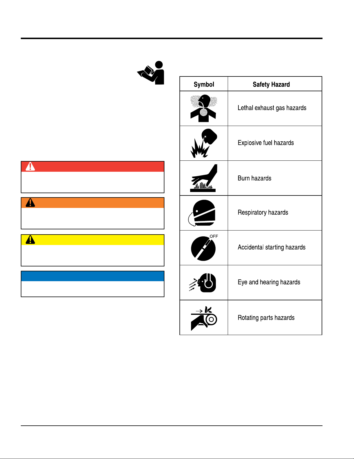
SAFETY MESSAGES
The four safety messages shown below will inform you
about potential hazards that could injure you or others. The
safety messages specifi cally address the level of exposure
to the operator and are preceded by one of four words:
DANGER, WARNING, CAUTION
SAFETY SYMBOLS
Potential hazards associated with the operation of this
equipment will be referenced with hazard symbols which
may appear throughout this manual in conjunction with
safety messages.
DANGER
Indicates a hazardous situation which, if not avoided,
WILL result in DEATH or SERIOUS INJURY.
WARNING
Indicates a hazardous situation which, if not avoided,
COULD result in DEATH or SERIOUS INJURY.
CAUTION
Indicates a hazardous situation which, if not avoided,
COULD result in MINOR or MODERATE INJURY.
or NOTICE.
NOTICE
Addresses practices not related to personal injury.
PAGE 6 — MVH408GH PLATE COMPACTOR • OPERATION AND PARTS MANUAL — REV. #0 (03/25/14)
Page 7
GENERAL SAFETY
NOTICE
This equipment should only be operated by trained and
Whenever necessary, replace nameplate, operation and
Manufacturer does not assume responsibility for any
accident due to equipment modifi cations. Unauthorized
use accessories or attachments that are not
recommended by Multiquip for this equipment. Damage
keep
Also, know the phone numbers
fi re department.
This information will be invaluable in the case of an
SAFETY INFORMATION
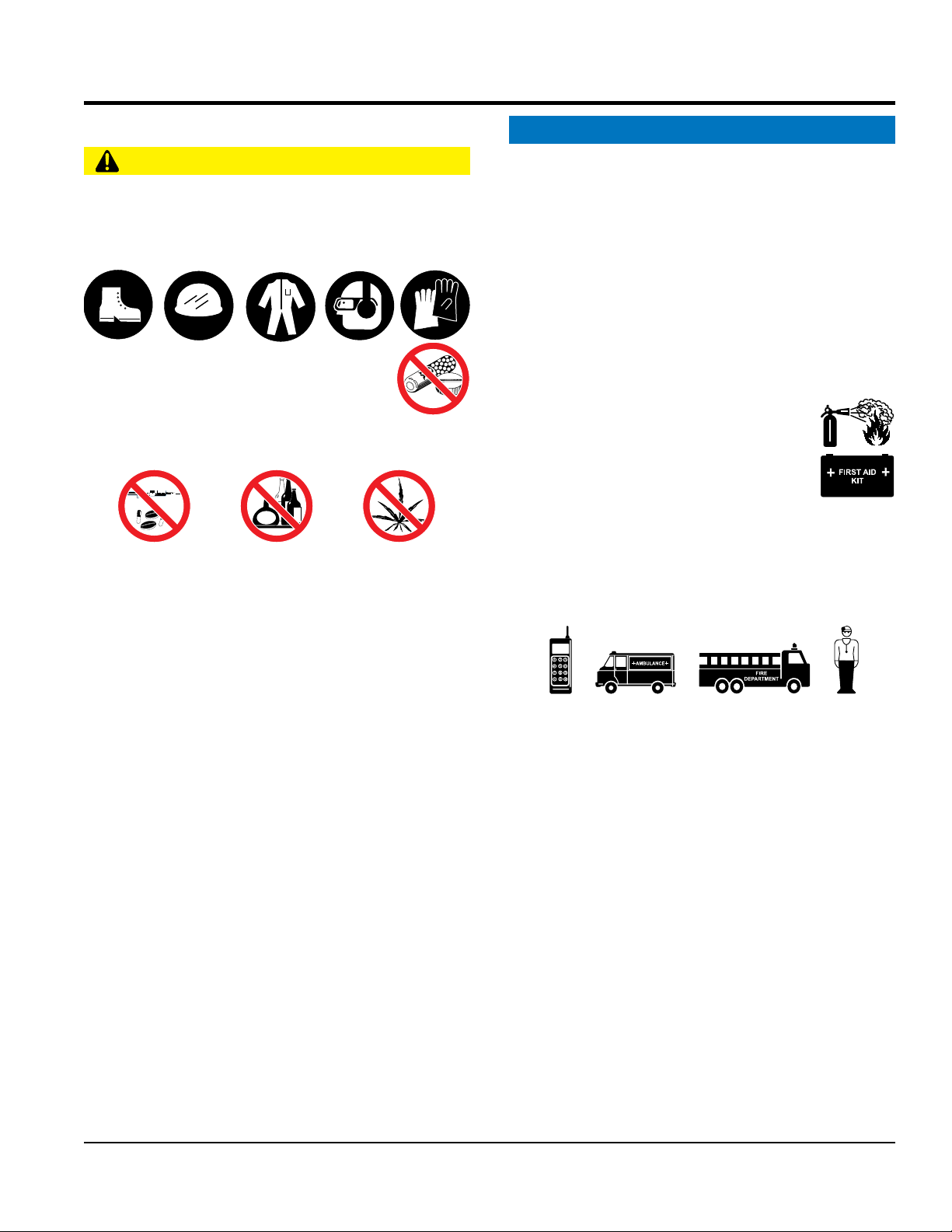
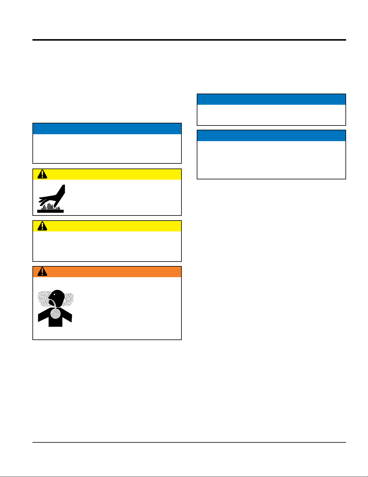
CAUTION
NEVER operate this equipment without proper protective
clothing, shatterproof glasses, respiratory protection,
hearing protection, steel-toed boots and other protective
devices required by the job or city and state regulations.
NEVER operate this equipment when not
feeling well due to fatigue, illness or when
under medication.
NEVER operate this equipment under the infl uence of
drugs or alcohol.
ALWAYS check the equipment for loosened threads or
bolts before starting.
DO NOT use the equipment for any purpose other than
its intended purposes or applications.
ALWAYS clear the work area of any debris, tools, etc.
that would constitute a hazard while the equipment is
in operation.
qualifi ed personnel 18 years of age and older.
safety decals when they become diffi cult read.
equipment modifi cation will void all warranties.
NEVER
to the equipment and/or injury to user may result.
ALWAYS know the location of the nearest
fi re extinguisher.
ALWAYS know the location of the nearest
fi rst aid kit.
ALWAYS know the location of the nearest phone or
a phone on the job site.
of the nearest ambulance, doctor and
emergency.
MVH408GH PLATE COMPACTOR • OPERATION AND PARTS MANUAL — REV. #0 (03/25/14)— PAGE 7
Page 8
SAFETY INFORMATION
COMPACTOR SAFETY
ENGINE SAFETY
place hands or fingers inside engine
operate the engine with heat shields or
engine is hot. High pressure boiling water will gush out
of the radiator and severely scald any persons in the
remove the engine oil drain plug while the
engine is hot. Hot oil will gush out of the oil tank and
severely scald any persons in the general area of the
run engine without an air fi lter or with a dirty air
fi lter. Severe engine damage may occur. Service air fi lter
tip the engine to extreme angles during lifting as
it may cause oil to gravitate into the cylinder head, making
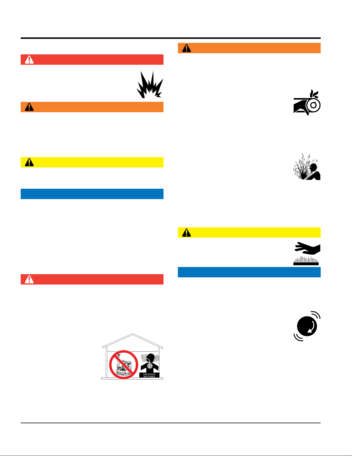
WARNING
DANGER
NEVER operate the equipment in an explosive
atmosphere or near combustible materials. An
explosion or fi re could result causing severe
bodily harm or even death.
WARNING
NEVER disconnect any emergency or safety devices.
These devices are intended for operator safety.
Disconnection of these devices can cause severe injury,
bodily harm or even death. Disconnection of any of these
devices will void all warranties.
CAUTION
NEVER lubricate components or attempt service on a
running machine.
NOTICE
ALWAYS keep the machine in proper running condition.
Fix damage to machine and replace any broken parts
immediately.
ALWAYS store equipment properly when it is not being
used. Equipment should be stored in a clean, dry location
out of the reach of children and unauthorized personnel.
DO NOT
compartment when engine is running.
NEVER
guards removed.
Keep fi ngers, hands hair and clothing away
from all moving parts to prevent injury.
DO NOT remove the radiator cap while the
general area of the compactor.
DO NOT remove the coolant drain plug
while the engine is hot. Hot coolant will
gush out of the coolant tank and severely
scald any persons in the general area of
the compactor.
DO NOT
compactor.
CAUTION
NEVER touch the hot exhaust manifold,
muffl er or cylinder. Allow these parts to cool
before servicing equipment.
DANGER
The engine fuel exhaust gases contain poisonous carbon
monoxide. This gas is colorless and odorless, and can
cause death if inhaled.
The engine of this equipment requires an adequate
free fl ow of cooling air. NEVER operate this equipment
in any enclosed or narrow
area where free fl ow of the
air is restricted. If the air
fl ow is restricted it will cause
injury to people and property
and serious damage to the
equipment or engine.
PAGE 8 — MVH408GH PLATE COMPACTOR • OPERATION AND PARTS MANUAL — REV. #0 (03/25/14)
NOTICE
NEVER
frequently to prevent engine malfunction.
NEVER tamper with the factory settings
of the engine or engine governor. Damage
to the engine or equipment can result
if operating in speed ranges above the
maximum allowable.
NEVER
MVH-306
the engine start diffi cult.
Page 9
SAFETY INFORMATION
FUEL SAFETY
BATTERY SAFETY (ELECTRIC START ONLY)
drop the battery. There is a possibility that the
keep the battery charged. If the battery is not
charge battery if frozen. Battery can explode.
When frozen, warm the battery to at least 61°F (16°C).
recharge the battery in a well-ventilated
environment to avoid the risk of a dangerous concentration
If the battery liquid (dilute sulfuric acid) comes into
, rinse eyes immediately with plenty
of water and contact the nearest doctor or hospital to
NEGATIVE battery terminal
keep battery cables in good working condition.
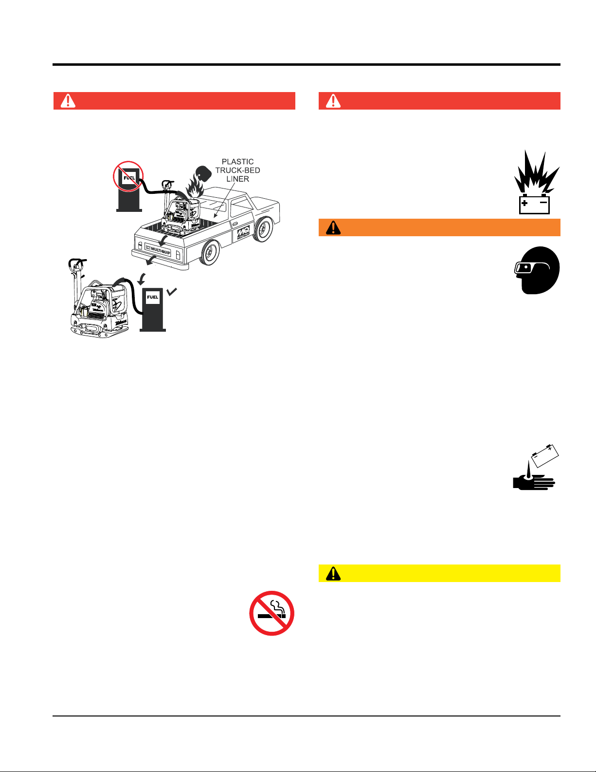
DO NOT add fuel to equipment if it is placed inside truck
DO NOT start the engine near spilled fuel or combustible
DANGER
bed with plastic liner. Possibility exists of explosion or
fi re due to static electricity.
MVH-306
MVH-306
fl uids. Diesel fuel is extremely fl ammable and its vapors
can cause an explosion if ignited.
DANGER
DO NOT
battery will explode.
DO NOT expose the battery to open fl ames,
sparks, cigarettes, etc. The battery contains
combustible gases and liquids. If these
gases and liquids come into contact with a
fl ame or spark, an explosion could occur.
WARNING
ALWAYS wear safety glasses when
handling the battery to avoid eye irritation.
The battery contains acids that can cause
injury to the eyes and skin.
Use well-insulated gloves when picking up
the battery.
ALWAYS
charged, combustible gas will build up.
DO NOT
ALWAYS refuel in a well-ventilated area, away from
sparks and open fl ames.
ALWAYS use extreme caution when working with
fl ammable liquids.
DO NOT fi ll the fuel tank while the engine is running
or hot.
DO NOT overfi ll tank, since spilled fuel could ignite if it
comes into contact with hot engine parts or sparks from
the ignition system.
Store fuel in appropriate containers, in well-ventilated
areas and away from sparks and fl ames.
NEVER use fuel as a cleaning agent.
DO NOT smoke around or near the
equipment. Fire or explosion could result
from fuel vapors or if fuel is spilled on a
hot engine.
ALWAYS
of combustible gases.
If the battery liquid (dilute sulfuric acid)
comes into contact with clothing or skin,
rinse skin or clothing immediately with
plenty of water.
contact with eyes
seek medical attention.
CAUTION
ALWAYS disconnect the
before performing service on the equipment.
ALWAYS
Repair or replace all worn cables.
MVH408GH PLATE COMPACTOR • OPERATION AND PARTS MANUAL — REV. #0 (03/25/14)— PAGE 9
Page 10

TRANSPORTING SAFETY
CAUTION
ENVIRONMENTAL SAFETY/
Decommissioning is a controlled process used to safely
retire a piece of equipment that is no longer serviceable.
If the equipment poses an unacceptable and unrepairable
safety risk due to wear or damage or is no longer cost
effective to maintain (beyond life-cycle reliability) and is to
be decommissioned (demolition and dismantlement),be
sure to follow rules below:
When the life cycle of this equipment is over, remove
battery and bring to appropriate facility for lead
reclamation. Use safety precautions when handling
When the life cycle of this equipment is over, it is
recommended that the trowel frame and all other metal
Metal recycling involves the collection of metal from
discarded products and its transformation into raw
materials to use in manufacturing a new product.
Recyclers and manufacturers alike promote the process
of recycling metal. Using a metal recycling center
The diesel engine used in this equipment has been
designed to reduce harmful levels of carbon monoxide
(CO), hydrocarbons (HC) and nitrogen oxides (NOx)
This engine has been certifi ed to meet US EPA Evaporative
Attempting to modify or make adjustments to the engine
emission system by unauthorized personnel without proper
training could damage the equipment or create an unsafe
Additionally, modifying the fuel system may adversely affect
evaporative emissions, resulting in fi nes or other penalties.
The emission control label is an integral part of the emission
If a replacement emission label is needed, please contact
NEVER allow any person or animal to stand underneath
the equipment while lifting.
NOTICE
Before lifting, make sure that the equipment parts (hook
and vibration insulator) are not damaged and screws are
not loose or missing.
Always make sure crane or lifi tng device has been
properly secured to the lifting bail (hook) of the
equipment.
ALWAYS shutdown engine before transporting.
NEVER lift the equipment while the engine is running.
Tighten fuel tank cap securely and close fuel cock to
prevent fuel from spilling.
SAFETY INFORMATION
batteries that contain sulfuric acid.
parts be sent to a recycling center.
promotes energy cost savings.
EMISSIONS INFORMATION
NOTICE
Use adequate lifting cable (wire or rope) of suffi cient
strength.
Use one point suspension hook and lift straight
upwards.
DO NOT lift machine to unnecessary heights.
ALWAYS tie down equipment during transport by
securing the equipment with rope.
DECOMMISSIONING
NOTICE
DO NOT pour waste or oil directly onto the ground, down
a drain or into any water source.
Contact your country's Department of
Public Works or recycling agency in your
area and arrange for proper disposal of
any electrical components, waste or oil
associated with this equipment.
contained in diesel exhaust emissions.
emissions requirements in the installed confi guration.
condition.
Emission Control Label
system and is strictly controlled by regulations.
The label must remain with the engine for its entire life.
your authorized Kohler Engine Distributor.
PAGE 10 — MVH408GH PLATE COMPACTOR • OPERATION AND PARTS MANUAL — REV. #0 (03/25/14)
Page 11
SPECIFICATIONS
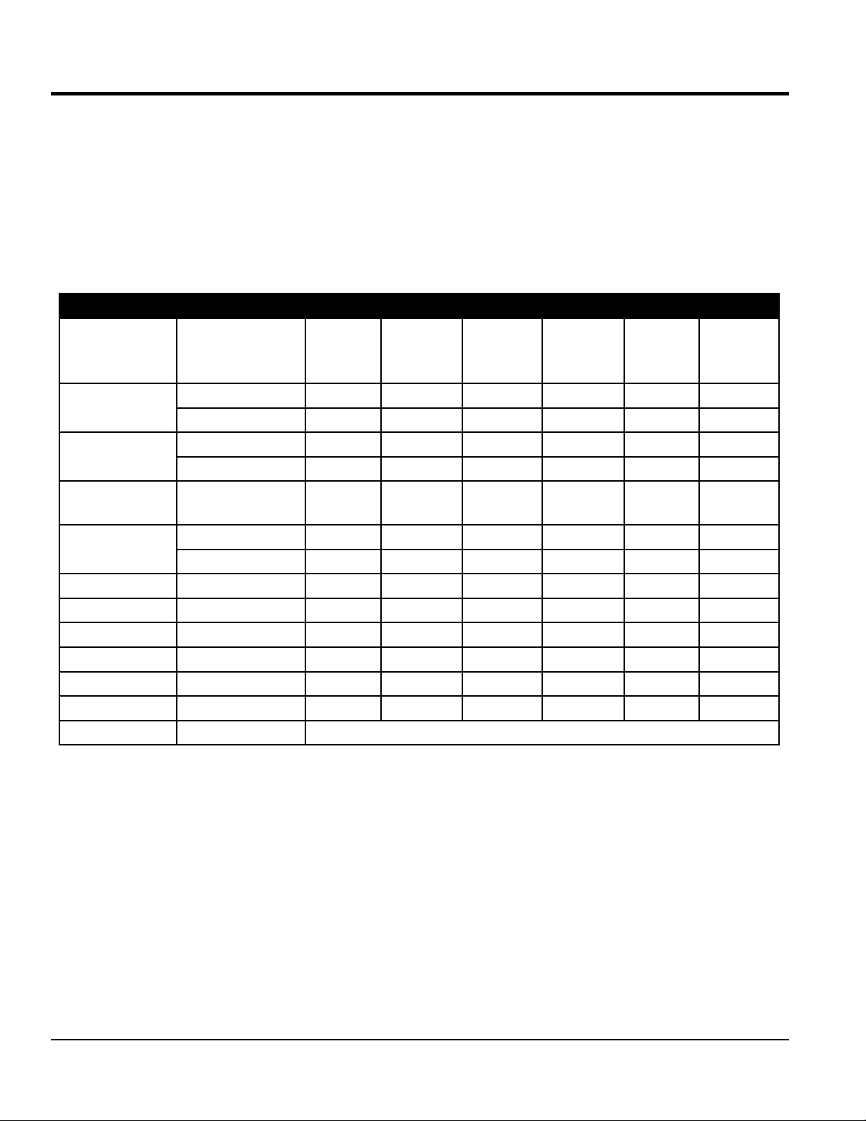
Table 1. MVH408GH Specifications
Centrifugal Force 12,365 lbf (55 kN)
Vibration Frequency 4,400 vpm (73 Hz)
Maximum Traveling Speed 82 ft/min (25 m/min)
Plate Size (W x L) 19.68 x 35.3 in (500 x 900 mm)
Plate Size (W x L) with extension plates 25.6 x 35.3 in (650 x 900 mm)
Max. Forward Speed 82 ft./min (25 m/min)
Operating Weight 802 lbs. (364 kg.)
Operating Weight with extension plates 836 lbs. (379 kg.)
Table 2. Engine Specifications
Engine Make HONDA
Engine Model GX390UT2SMXC
Engine Type Air-cooled, 4 stroke Gasoline Engine
Cylinder Bore X Stroke 3.46 in. x 2.52 in. (88 mm x 64 mm)
Displacement 23.74 cu-in (389 cc)
Maximum Ouput 11.7 BHP (8.7 kW) @ 3600 RPM
Fuel Tank Capacity Approx. 1.4 U.S. gallons (6.1 liters)
Fuel Type Unleaded 86 Octane or Higher
Oil Capacity 1.16 qts (1.1 liters)
Starting Method Recoil Start
Dry Net Weight Recoil/Electric 69.89 lbs (31.7 Kg.)
Dimensions (L x W x H) 15.98 x 18.11 x 17.64 in (406 x 460 x 448 mm)
MVH408GH PLATE COMPACTOR • OPERATION AND PARTS MANUAL — REV. #0 (03/25/14)— PAGE 11
Page 12
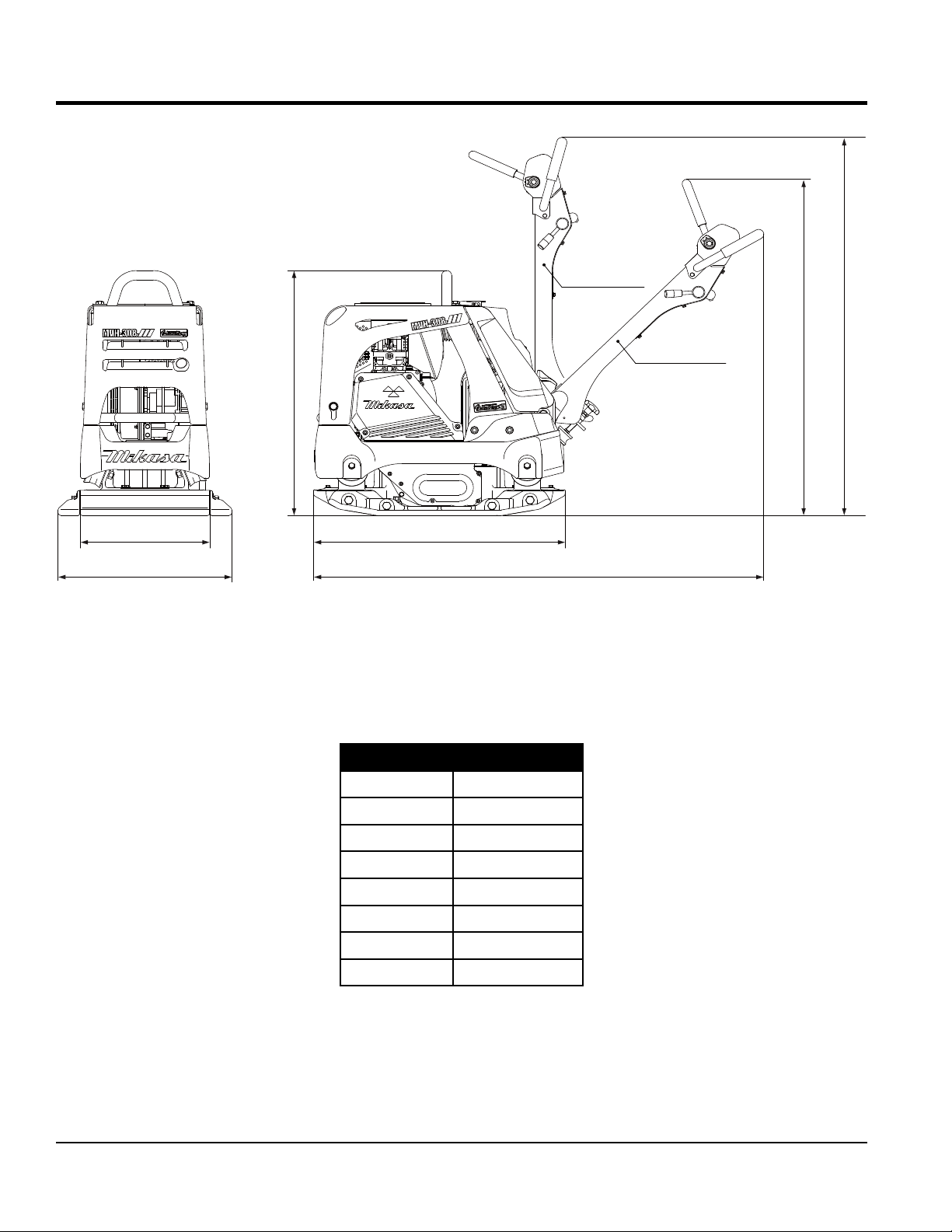
DIMENSIONS
Stored position
D
Working position
C
E
A
B
extension plate (option)
F
G
Figure 1. Dimensions
Table 3. Dimensions
REF. DES IN. (MM)
A 19.68 (500)
B 25.60 (650)
C 36.61 (930)
D 47.64 (1210)
E 53.54 (1360)
F 35.3 (900)
G 62.01 (1575)
PAGE 12 — MVH408GH PLATE COMPACTOR • OPERATION AND PARTS MANUAL — REV. #0 (03/25/14)
Page 13

GENERAL INFORMATION
DEFINITION OF PLATE COMPACTOR
The Mikasa MVH408GH is a reversible plate compactor
designed for efficient compaction of sand, graveland
cohesive soils. This plate compactor is a powerful
compacting tool capable of applying a tremendous force
in consecutive high frequency vibrations to a soil surface.
Its applications include compacting for road, embankments
and reservoirs as well as backfilling for gas pipelines, water
pipelines and cable installation work.
VIBRATORY PLATES
The vibratory plates of the compactor produce low
amplitude high frequency vibrations, designed to compact
granular soils and asphalt.
The resulting vibrations cause forward motion. The engine
and handle are vibration isolated from the vibrating plate.
FREQUENCY/SPEED
The compactor's vibrating plate produces a vibration
frequency of 4,400 VPM (vibrations per minute).
The travel speed of the compactor is approximately
82 ft/minute (25 meters/minute).
ENGINE
This plate compactor is equipped with a Honda
GX390UT2SMXC air cooled, 4-cycle gasoline engine.
The engine drives an eccentric weight at a high speed to
develop a compaction force.
CONTROLS
Before starting the plate compactor identify and understand
the function of all the controls and components.
MVH408GH PLATE COMPACTOR • OPERATION AND PARTS MANUAL — REV. #0 (03/25/14)— PAGE 13
Page 14
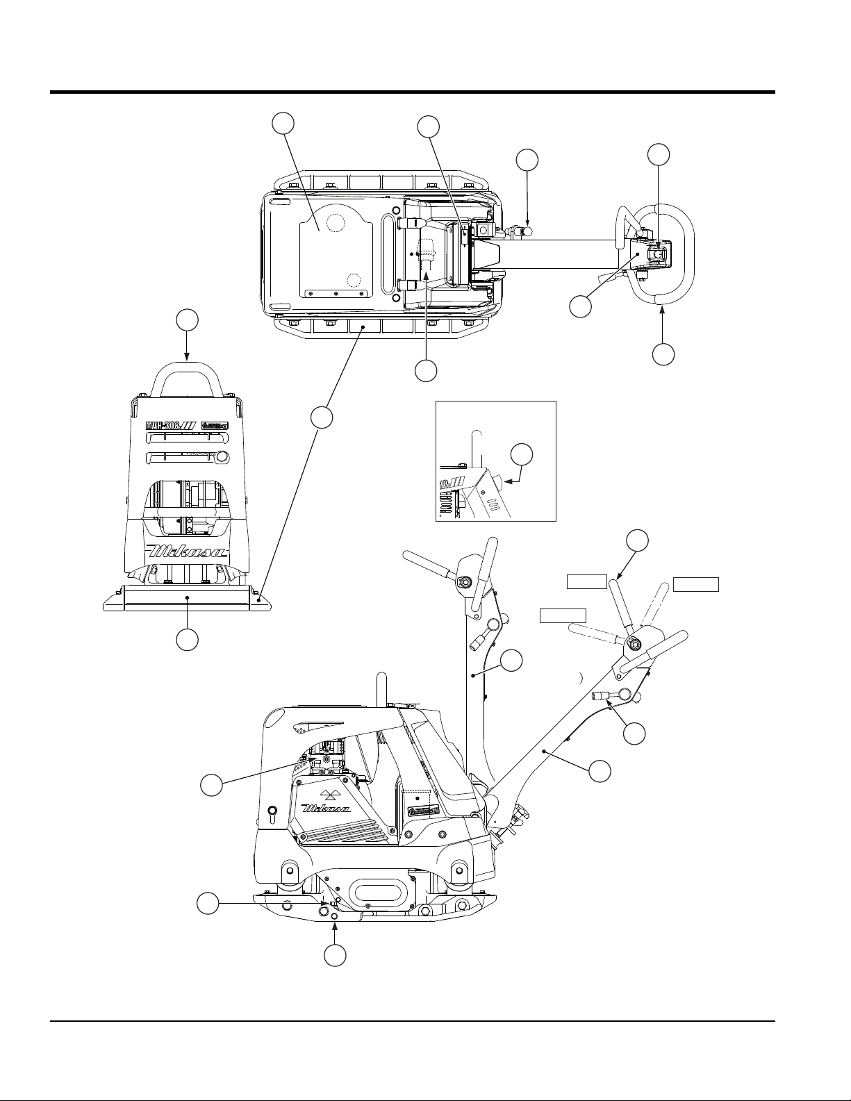
COMPONENTS
1
8
10
2
3
5
7
17
4
6
12
Neutral
Forward
9
11
(Stored position
13
11
16
15
(Working position)
Reverse
14
Figure 2. Plate Compactor Components
PAGE 14 — MVH408GH PLATE COMPACTOR • OPERATION AND PARTS MANUAL — REV. #0 (03/25/14)
Page 15

COMPONENTS
Figure 2 shows the location of the basic controls and
components of the MVH408GH Plate Compactor. The
function of each control is described below:
1. Rubber Cover — Lift this rubber cover to gain access
to the fuel tank.
2. Hour/Tachometer — Displays the cumulative time
that the machine has been in use. During operation it
displays the rpm reading.
3. Handle Bar Height Adjuster — Adjusts the the handle
bar to the desired height by loosening the wing nut and
turning the grip clockwise to raise the handle bar and
counterclockwise to lower the handle bar.
4. Breather Plug — Allow pressure to escape to the air
in the form of a gas from heat.
5. Hydraulic Pump (Oil Reservoir) — Regulates
hydraulic oil flow produced by the direction of the
control lever.
6. Hand Grip — When operating the compactor use this
hand grip to maneuver the compactor.
7. Cyclone Cleaner — Filters large dust particles to keep
air cleaner from getting clogged easily.
8. Lifting Bale — When lifting of the compactor is
required either by forklift, crane etc., tie rope or chain
around this lifting point.
9. Vibrating Plate — A flat, open plate made of durable
cast iron construction used in the compacting of soil.
10. Extension Plate — Provides additional area of
vibration to the vibrating plate.
11. Handle Bar — When operating the compactor, this
handle is to be in the downward position. When the
compactor is to be stored, move the handle bar to
the upright position.
12. Direction Control Lever — Push the lever forward to
move compactor in a forward direction. Pull the lever
backwards to move compactor in backwards direction.
Placing the lever in the middle (midway) will cause the
compactor not to move (neutral).
Throttle Lever — Controls speed of the plate
13.
compactor. Place straight vertically to start, push fully
counterclockwise for full throttle and fully clockwise to
stop plate compactor.
14. Vibrator Oil Drain Plug — Used to drain vibrator oil
from the machine.
15. Vibration Case Oil Filler — Used to add oil to the
vibration case.
16. Engine — This plate compactor uses a GX390UT2SMXC
gasoline engine. Refer to the owner’s manual for
engine information.
17. Engine ON-OFF Switch — Used to turn the engine
on or off.
MVH408GH PLATE COMPACTOR • OPERATION AND PARTS MANUAL — REV. #0 (03/25/14)— PAGE 15
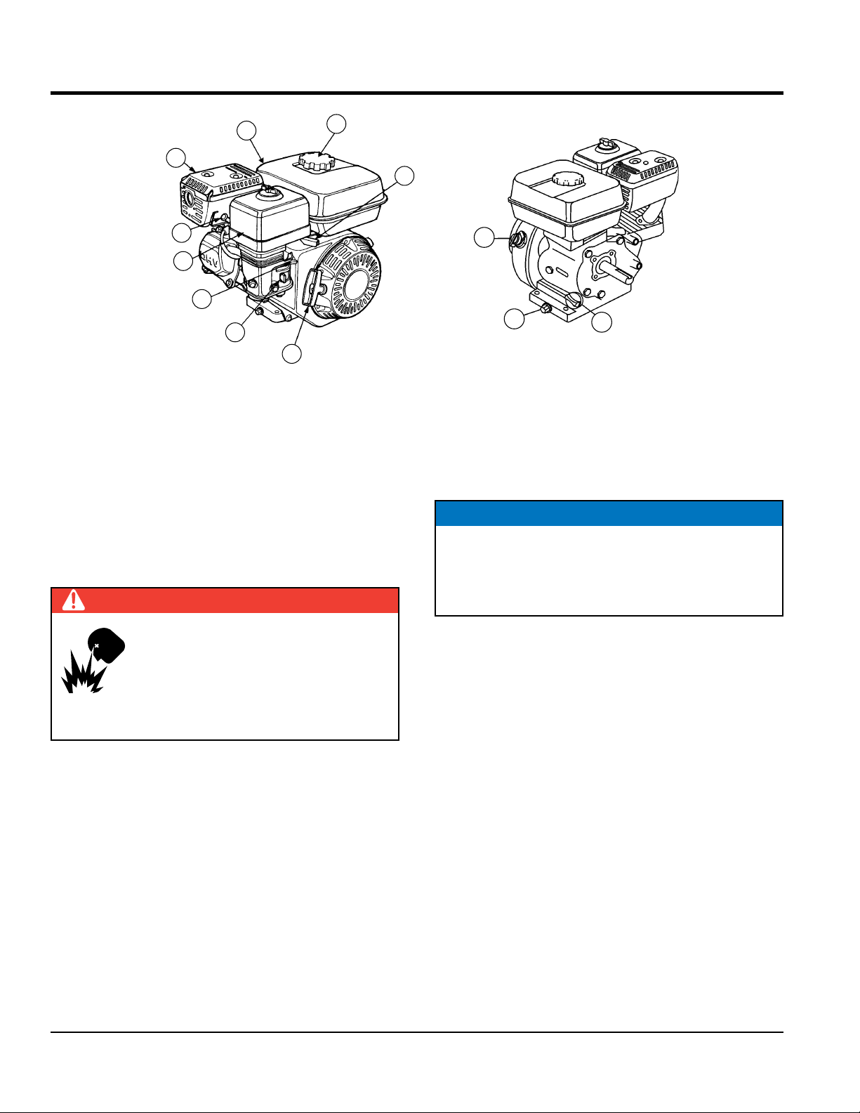
Page 16
BASIC ENGINE
9
8
7
6
5
4
3
Figure 3. Engine Controls and Components
1
INITIAL SERVICING
The engine (Figure 3) must be checked for proper
lubrication and filled with fuel prior to operation. Refer to the
manufacturer's engine manual for instructions and details
of operation and servicing.
1. Fuel Filler Cap – Remove this cap to add unleaded
gasoline to the fuel tank. Make sure cap is tightened
securely. DO NOT over fill.
DANGER
2
12
11
10
6. Air Cleaner – Prevents dirt and other debris from
entering the fuel system. Remove wing-nut on top of
air filter canister to gain access to filter element.
NOTICE
Operating the engine without an air filter, with a
damaged air filter, or a filter in need of replacement
will allow dirt to enter the engine, causing rapid engine
wear.
Add fuel to the tank only when the engine
is stopped and has had an opportunity to
cool down. In the event of a fuel spill, DO
NOT attempt to start the engine until the
fuel residue has been completely wiped up
and the area surrounding the engine is dry.
2. Throttle Lever – Used to adjust engine RPM speed.
For normal operation this lever should always be placed
in the RUN position.
3. Recoil Starter (Pull Rope) – Manual-starting method.
Pull the starter grip until resistance is felt, then pull
briskly and smoothly.
4. Fuel Valve Lever – OPEN to let fuel flow, CLOSE to
stop the flow of fuel.
5. Choke Lever – Used in the starting of a cold engine,
or in cold weather conditions. The choke enriches the
fuel mixture.
7. Spark Plug – Provides spark to the ignition system.
Set spark plug gap according to engine manufacturer's
instructions. Clean spark plug once a week.
8. Muffler – Used to reduce noise and emissions. NEVER
touch when hot!
9. Fuel Tank – Fill with unleaded gasoline. Reference
Table 2 for fuel tank capacity. For additional information
refer to Honda engine owner's manual.
10. Dipstick/Oil Filler Cap – Remove this cap to determine
if the engine oil is low. Add oil through this filler port as
recommended in (Table 4).
11. Oil Drain Plug – Remove this plug to remove oil from
the engine's crankcase.
12. Engine ON/OFF Switch – ON position permits engine
starting, OFF position stops engine operation.
PAGE 16 — MVH408GH PLATE COMPACTOR • OPERATION AND PARTS MANUAL — REV. #0 (03/25/14)
Page 17
INSPECTION
BEFORE STARTING
1. Read all safety instructions at the beginning of manual.
2. Clean the compactor, removing dirt and dust,
particularly the engine cooling air inlet, carburetor and
air cleaner.
3. Check the air filter for dirt and dust. If air filter is dirty,
replace air filter with a new one as required.
4. Check carburetor for external dirt and dust. Clean with
dry compressed air.
5. Check fastening nuts and bolts for tightness.
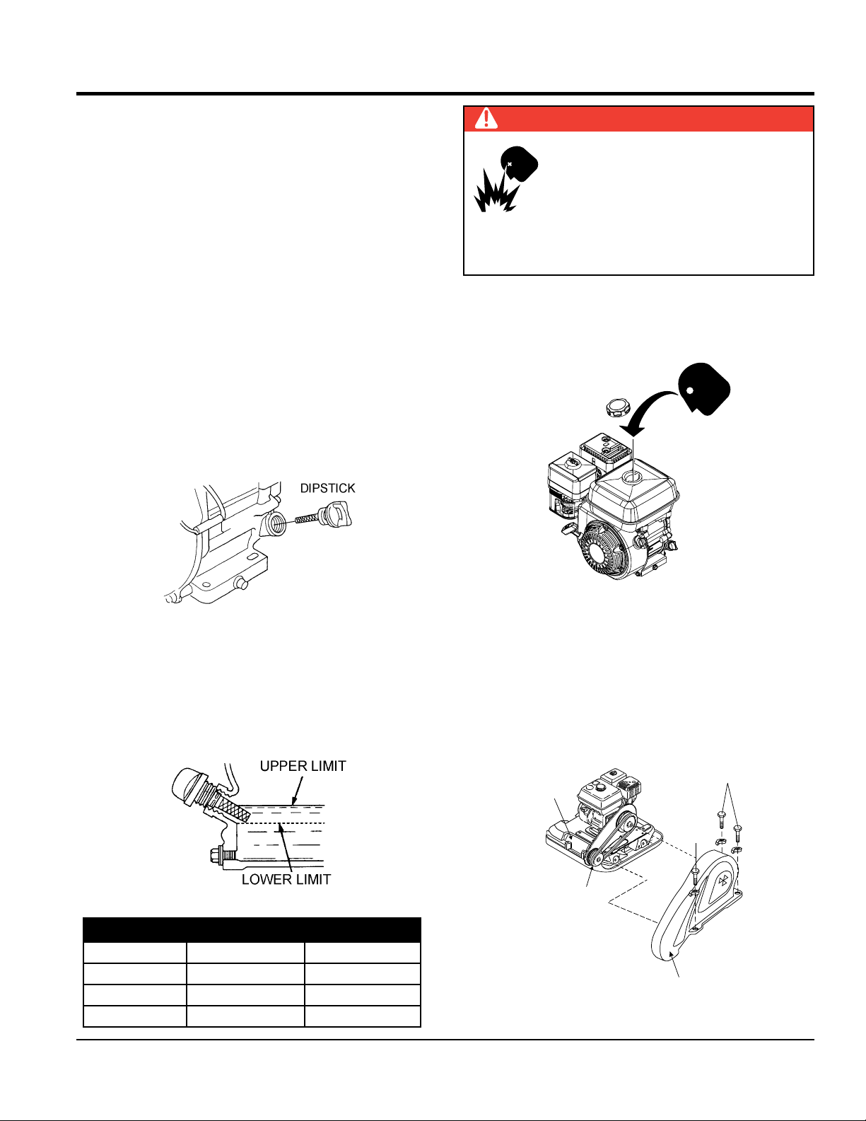
ENGINE OIL CHECK
1. To check the engine oil level, place the compactor on
secure level ground with the engine stopped.
2. Remove the dipstick from the engine oil filler hole
(Figure 4) and wipe clean.
DANGER
EXPLOSIVE FUEL!
Motor fuels are highly flammable and can
be dangerous if mishandled. DO NOT
smoke while refueling. DO NOT attempt
to refuel the compactor if the engine is
hot! or running.
FUEL CHECK
1. Visually inspect (Figure 6) to see if fuel level is low. If
fuel is low, replenish with unleaded fuel.
FUEL
CAP
Figure 4. Engine Oil Dipstick Removal
3. Insert and remove the dipstick without screwing it into
the filler neck. Check the oil level shown on the dipstick.
4. If the oil level is low (Figure 5), fill to the edge of the
oil filler hole with the recommended oil type as listed
in Table 4. Refer to Table 2 for maximum engine oil
capacity.
Figure 5. Engine Oil Dipstick (Oil Level)
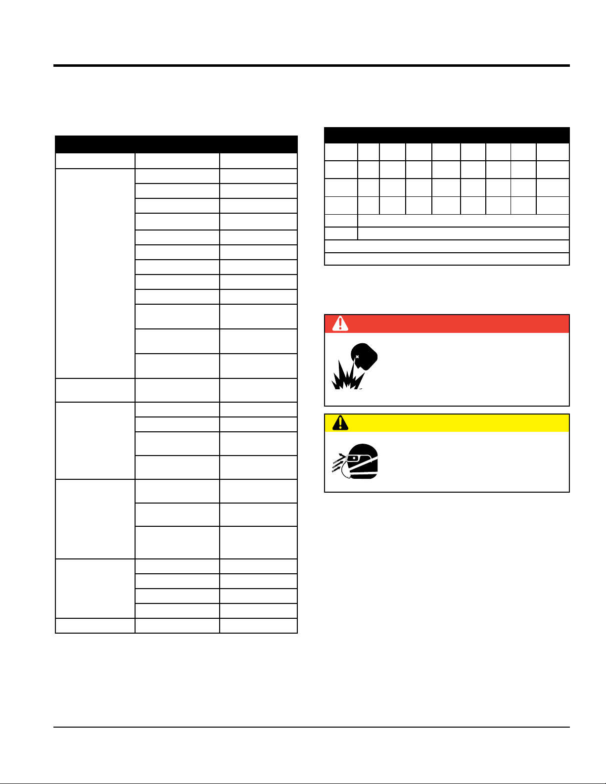
Table 4. Oil Type
Season Temperature Oil Type
Summer 25°C or Higher SAE 10W-30
Spring/Fall 25°C~10°C SAE 10W-30/20
Winter 0°C or Lower SAE 10W-10
Figure 6. Fuel Check
2. When refueling, be sure to use a strainer for filtration.
DO NOT top-off fuel. Wipe up any spilled fuel
immediately.
V-BELT COVER REMOVAL
To inspect the V-belt, remove the three bolts that secure
the belt cover to the frame as shown in Figure 7.
REMOVE
VIBRATOR
REMOVE
V-BELT
Mikasa
V-BELT COVER
Figure 7. V-Belt Cover Removal
MVH408GH PLATE COMPACTOR • OPERATION AND PARTS MANUAL — REV. #0 (03/25/14)— PAGE 17
Page 18
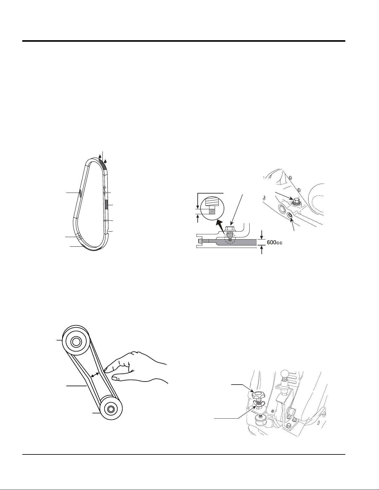
MISSING RUBBER
INSPECTION
V-BELT INSPECTION
Visually examine the V-belt (Figure 8) and determine if it
is full of tiny cracks, frayed, has pieces of rubber missing,
is peeling or otherwise damaged.
Also, examine the belt and determine if it is oil soaked or
"glazed " (hard shiny appearance on the sides of the belt).
Either of these two conditions can cause the belt to run hot,
which can weaken it and increase the danger of it breaking.
If the V-belt exhibits any of the referenced wear conditions
replace the V-belt immediately
OIL SOAKED
GLAZED
CORD FAILURE
WORN BACK
COVER
BROKEN
VIBRATOR OIL CHECK
1. Place the plate compactor horizontally on a flat surface.
Make sure the compactor is level when checking the
oil in the vibrator assembly.
2. Check vibrator oil level by removing the oil plug (vibrator
oil gauge) as shown in Figure 10. Clean the oil gauge
and re-thread back in. Remove the oil gauge again and
confirm oil level does not exceed the cross hash of the
oil plug. DO NOT OVERFILL
3. The vibrator holds approximately 20.3 oz. (600 cc).
IMPORTANT, if oil is required, replace using only SAE
10W-30 motor oil.
Oil gauge
Effective
(19mm wrench)
CRACKS
SIDEWALL
WEAR
Figure 8. Drive Belt Inspection
V-BELT TENSION
The V-belt tension is proper if the V-belt bends 10 to 15 mm
(Figure 9) when depressed with finger at midway between
the clutch and vibrator pulleys.
CORRECT V-BELT
CLUTCH
PULLEY
V-BELT
VIBRATOR
PULLEY
TENSION 10-15 MM
WHEN DEPRESSED
AS SHOWN.
Drain plug
(14mm wrench)
Figure 10. Vibrator Oil Check
HANDLE BAR
The height of the handle bar can be adjusted for ease of
use. Adjust the handle height as follows. Refer to Figure 11.
1. Loosen the wing nut.
2. Turn the grip clockwise to raise the handle or
counterclockwise to lower the handle.
3. When the handle bar is raised to the desired height,
tighten the wing nut.
Grip
Wing nut
Figure 9. V-Belt Tension
Figure 11. Handle Height Adjustment
PAGE 18 — MVH408GH PLATE COMPACTOR • OPERATION AND PARTS MANUAL — REV. #0 (03/25/14)
Page 19
STARTUP
CLOSED
CAUTION
DO NOT attempt to operate the compactor
until the Safety, General Information and
Inspection sections of this manual have
been read and thoroughly understood.
This section is intended to assist the operator with the
initial startup of the compactor. It is extremely important
that this section be read carefully before attempting to use
the compactor in the field.
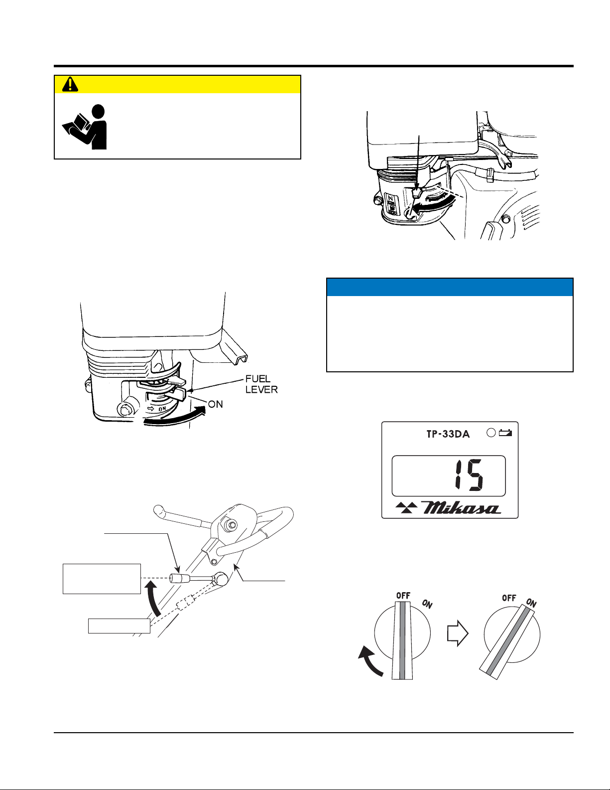
STARTING THE ENGINE
1. Place the engine fuel valve lever (Figure 12) to the
“ON” position.
3. Place the choke lever (Figure 14) in the “CLOSED”
position if starting a cold engine.
CHOKE LEVER
Figure 14. Choke Lever (Closed)
NOTICE
The CLOSED position of the choke lever enriches the
fuel mixture for starting a COLD engine. The OPEN
position provides the correct fuel mixture for normal
operation after starting, and for restarting a warm
engine.
Figure 12. Engine Fuel Valve Lever (ON Position)
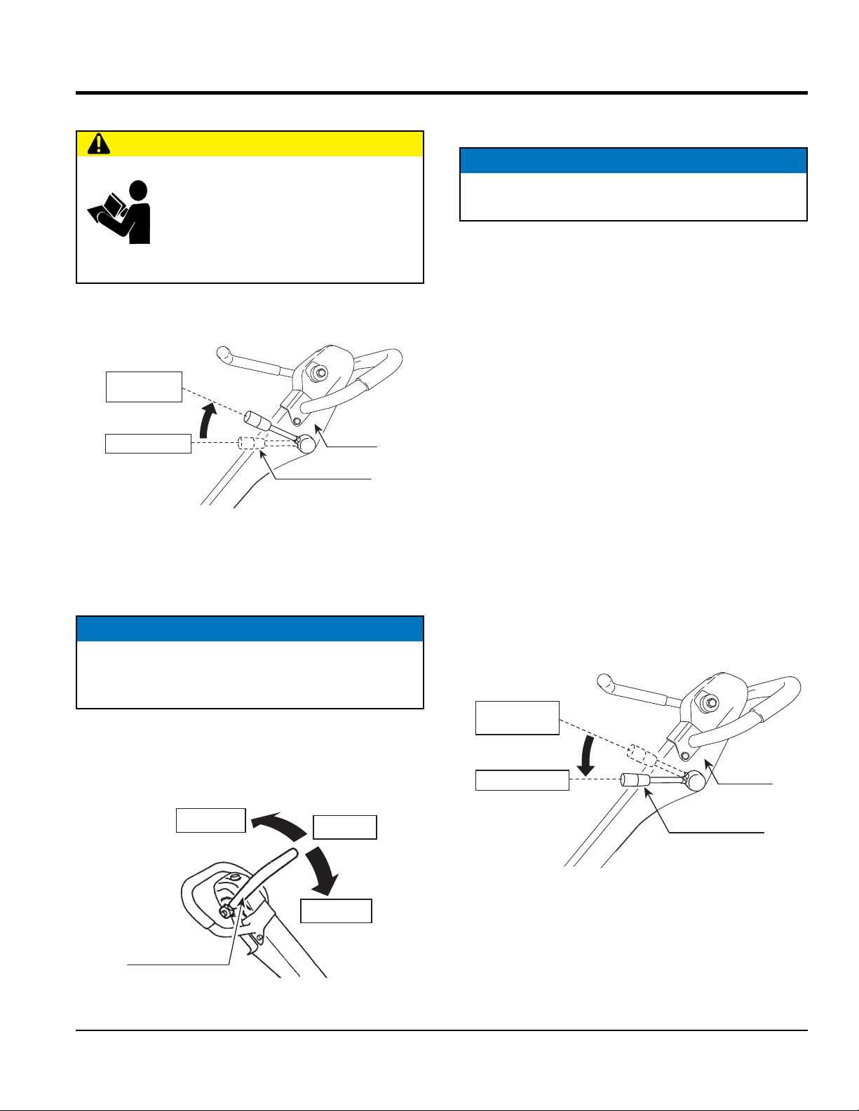
2. Move the throttle lever (Figure 13) slightly higher from
the idle position.
Throttle lever
Slightly higher
position
Idle position
Figure 13. Throttle Lever (Higher Position)
Handle
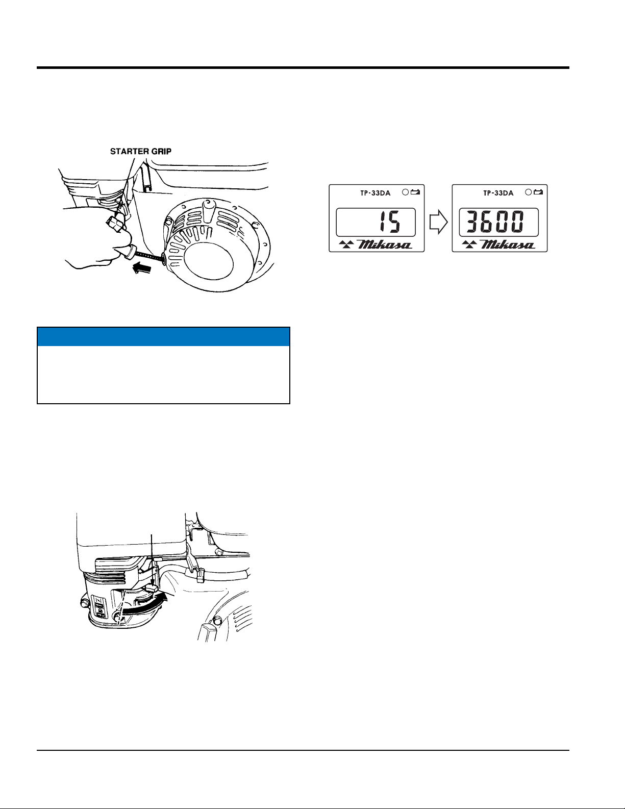
4. When the engine is stopped, the hour tachometer
always shows "cumulative time" (Figure 15).
ENGINE TACH
DIESEL
Figure 15. Hour Tachometer (Cumulative Time)
&HOUR
METER
HRS
5. Place the engine ON/OFF switch (Figure 16) in the
"ON" position.
Figure 16. Engine ON/OFF Switch (ON Position)
MVH408GH PLATE COMPACTOR • OPERATION AND PARTS MANUAL — REV. #0 (03/25/14)— PAGE 19
Page 20
STARTUP
6. Grasp the starter grip (Figure 17) and slowly pull it
out. The resistance becomes the hardest at a certain
position, corresponding the compression point. Rewind
the rope a little from that point and pull out sharply.
Figure 17. Starter Grip
NOTICE
DO NOT pull the starter rope all the way to the end
9. Before the compactor is placed in to operation, run the
engine for several minutes. Check for fuel leaks, and
noises that would associate with a loose component.
10. During operation, the hour tachometer displays
"rotation number" (Figure 19).
Cumulative time
ENGINE TACH
&HOUR
DIESEL
METER
HRS
Figure 19. Hour Tachometer (Rotation Number)
Rotation number
ENGINE TACH
&HOUR
DIESEL
METER
RPM
DO NOT release the starter rope after pulling. Allow it
to rewind as soon as possible.
7. When engine starts, release the starter grip and allow
the rope to recoil.
8. If the choke lever was moved to the "CLOSED" position
to start the engine, gradually move it to the "OPEN"
position (Figure 18) as the engine warms up. If the
engine has not started, repeat steps 1 through 6.
CHOKE
LEVER
OPEN
Figure 18. Choke Lever (Open)
PAGE 20 — MVH408GH PLATE COMPACTOR • OPERATION AND PARTS MANUAL — REV. #0 (03/25/14)
Page 21
OPERATION
OPERATION
CAUTION
ALWAYS follow all safety rules in the safety
section of this manual before operating
compactor. Keep work area clear of debris
and other objects that could cause bodily
injury or damage to the compactor.
1. Once the engine has started, move the engine throttle
lever quickly to the operation position (Figure 20).
Operation
position
Idle position
Throttle lever
Figure 20. Throttle Lever (Operation Position)
2. With the throttle lever in the run position, the engine
speed should be around 2,300 RPM, therefore
engaging the centrifugal clutch.
NOTICE
ALWAYS move the throttle lever quickly without
hesitation, because increasing the engine speed slowly
causes the clutch to slip.
3. Using the direction control lever, move the machine
backward or forward (Figure 21). When the direction
control lever is pushed forward, the machine moves
forward. When pulled backward, the machine moves
backward.
Reverse
Handle
Neutral
4. When the direction control lever is the neutral position,
the machine vibrates staying at the same location
NOTICE
NEVER stop the engine suddenly while working at
high speeds.
5. Compactor traveling speed may drop on soils which
contain clay, however there may be cases where
traveling speed drops because the compaction plate
does not leave the ground surface easily due to the
composition of the soil. To rectify this problem do the
following:
• Check the bottom plate to see if clay or equivalent
material has been lodged in the plate mechanism. If
so, wash with water and remove.
• Remember the compactor does not work as efficiently
on clay or soils that have a high moisture content level.
• If the soil has a high moisture level, dry soil to
appropriate moisture content level or carry out
compaction twice.
STOPPING THE ENGINE
Normal Shutdown
1. Move the throttle lever to the idle position (Figure 22)
and run the engine for three minutes at low speed.
Operation
position
Idle position
Throttle lever
Handle
Forward
Direction
control lever
Figure 21. Direction Control Lever
Figure 22. Throttle Lever (Idle)
MVH408GH PLATE COMPACTOR • OPERATION AND PARTS MANUAL — REV. #0 (03/25/14)— PAGE 21
Page 22
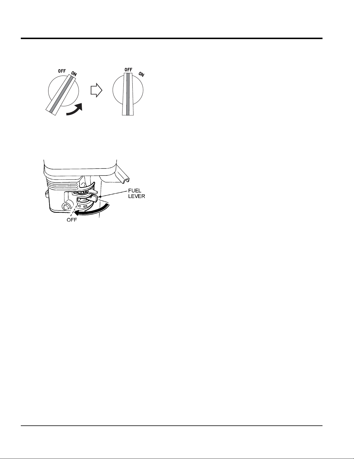
2. Place the engine ON/OFF switch (Figure 23) in the
OFF position.
Figure 23. Engine ON/OFF Switch (OFF Position)
3. Place the fuel shut-off lever (Figure 24) in the OFF
position.
OPERATION
Figure 24. Fuel Valve Lever (OFF)
Emergency Shutdown
1. Move the throttle lever quickly to the IDLE position, and
place the engine ON/OFF switch in the OFF position.
PAGE 22 — MVH408GH PLATE COMPACTOR • OPERATION AND PARTS MANUAL — REV. #0 (03/25/14)
Page 23
MAINTENANCE
GENERAL MAINTENANCE
General maintenance practices are crucial to the
performance and longevity of your compactor. This
equipment requires routine cleaning, inspection and
lubrication. Refer to Table 5 and Table 6 for scheduled
engine and compactor maintenance.
The following maintenance procedures can prevent serious
compactor damage or malfunctioning.
NOTICE
Refer to HONDA engine manual supplied with your
compactor for more detailed engine maintenance and
troubleshooting.
CAUTION
ALWAYS allow the engine to cool before
servicing. NEVER attempt any maintenance
work on a hot engine.
General Cleanliness
Clean the compactor daily. Remove all dust and debris
buildup (mud, clay etc.). If the compactor is steam-cleaned,
ensure that lubrication is accomplished AFTER steam
cleaning.
NOTICE
Inspection and other services should always be carried
out on hard and level ground with the engine shut down.
NOTICE
The inspection intervals listed in the maintenance tables
are for operation under normal conditions. Adjust your
inspection intervals based on the number hours plate
compactor is in use, and particular working conditions.
CAUTION
ALWAYS disconnect the spark plug wire from the spark
plug and secure away from the engine before performing
maintenance or adjustments on the machine.
WARNING
Some maintenance procedures may
require the engine to be run. Ensure
that the maintenance area is well
ventilated. Gasoline engine exhaust
contains poisonous carbon monoxide
gas that can cause unconsciousness
and may result in DEATH.
MVH408GH PLATE COMPACTOR • OPERATION AND PARTS MANUAL — REV. #0 (03/25/14)— PAGE 23
Page 24
To make sure your plate compactor is always in good
working condition before using, carry out the maintenance
inspection in accordance with Table 5 and Table 6.
ENGINE MAINTENANCE
Perform engine maintance as listed in Table 5.
Table 5. Engine Maintenance Schedule
MAINTENANCE
First
Description (3) Operation Before
Engine Oil
Air Cleaner
All Nuts and
Bolts
Spark Plug
Cooling Fins CHECK X
Spark Arrester CLEAN X
Fuel Tank CLEAN X
Fuel Filter CHECK X
Idle Speed CHECK-ADJUST X (2)
Valve Clearance CHECK-ADJUST X (2)
Fuel lines CHECK Every 2 years (replace if necessary) (2)
CHECK X
CHANGE X
CHECK X
CHANGE X (1)
Re-tighten If
Necessary
CHECK-CLEAN X
REPLACE X
X
Month or
10 hrs
Every 3
Months or
25 hrs
Every 6
Months or
50 hrs
Every
Year or
100 hrs
Every 2
Years or
200 hrs
1. Service more frequently when used in DUSTY areas.
2. These items should be serviced by your service dealer, unless you have the proper tools and are mechanically proficient.
Refer to the HONDA Shop Manual for service procedures.
3. For commercial use, log hours of operation to determine proper maintenance intervals.
PAGE 24 — MVH408GH PLATE COMPACTOR • OPERATION AND PARTS MANUAL — REV. #0 (03/25/14)
Page 25
MAINTENANCE
MACHINE INSPECTION
Perform machine inspection as listed in Table 6.
Table 6. Machine Inspection
Interval Check Solution
Machine Clean if necessary.
Fuel Tank For Leaks Repair fuel leaks.
Fuel System for Leaks Repair fuel leaks.
Engine Oil Add oil if necessary.
Vibrator Oil Add oil if necessary.
Air Cleaner Element Clean/Replace
Daily Before Starting
Every 20 Hours Engine Oil/Oil Filter
Every 100 Hours
Every 200 hours
Every 300 hours
Every 2 years Fuel Lines Replace
Guard Frame Inspect/deformations
Shock Absorber Replace if damaged.
Hydraulic pump Check/Repair Leaks
Hydraulic Pipe System
Direction Control Lever
Duct Hose
Engine Oil Change
Engine Oil Filter Wash
Vibrator Oil
Hydraulic Oil
V-Belt
Clutch
Engine Bolts
Vibrator Oil Change
Fuel Filter Change
Hydraulic Oil Change
Engine Oil Filter Change
Check/Repair leaks,
Inspect for wear
Check bolts/nuts,
Inspect for wear
Check for crack/
damage
Replace only after
first 20 hrs.
Check oil level.
Check for leaks/dirt.
Check oil level.
Check for leaks.
Inspect, replace if
damaged or worn.
Inspect, replace if not
working properly.
Replace bolts
if deformed or
elongated.
TIGHTENING TORQUE
Reference Table 7 below (Tightening Torque ), for retightening of nuts and bolts.
Table 7. Tightening Torque (in. kg/cm Diameter)
Material
Bolt threads used with this machine are all right handed
Material and quality of material is marked on each bolt, and screw.
6mm 8mm 10mm 12mm 14mm 16mm 18mm 20mm
4T 70 150 300 500 750 1,100 1,400 2,000
6-8T 100 250 500 800 1,300 2,000 2,700 3,800
11T 150 400 800 1,200 2,000 2,900 4,200 5,600
*
100 (6mm) 300 ~ 350 (8mm) 650 ~ 700 (10mm)
**
In case counter-part is of aluminum
ENGINE AIR CLEANER
DANGER
DO NOT use gasoline or low flash point
solvents for cleaning the air cleaner. The
possibility exists of fire or explosion which
can cause damage to the equipment and
severe bodily harm or even DEATH!
CAUTION
Wear protective equipment such as
approved safety glasses or face shields
and dust masks or respirators when
cleaning air filters with compressed air.
This engine is equipped with a replaceable, high-density
paper air cleaner element. See Figure 25 for air cleaner
components.
1. Remove the air cleaner cover and foam filter element.
2. Tap the paper filter element several times on a hard
surface to remove dirt, or blow compressed air not
exceeding 30 psi (207 kPa, 2.1 kgf/cm2) through the
filter element from the inside out. NEVER brush off
dirt. Brushing will force dirt into the fibers. Replace the
paper filter element if it is excessively dirty.
MVH408GH PLATE COMPACTOR • OPERATION AND PARTS MANUAL — REV. #0 (03/25/14)— PAGE 25
Page 26
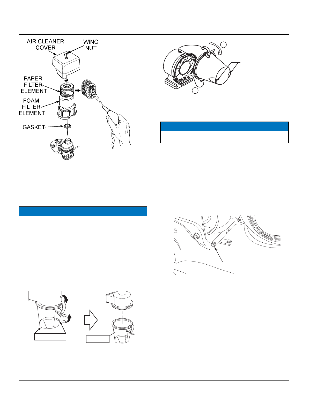
BLOW COMPRESSED
AIR FROM THE
INSIDE OUT
Figure 25. Engine Air Cleaner
3. Clean foam element in warm, soapy water or
nonflammable solvent. Rinse and dry thoroughly. Dip
the element in clean engine oil and completely squeeze
out the excess oil from the element before installing.
NOTICE
MAINTENANCE
2
Lock
Dust exhaust
1
Figure 27. Latching Dust Pot
ENGINE OIL
NOTICE
Drain the engine oil when the oil is warm.
1. Remove the oil drain bolt (Figure 28). and sealing
washer and allow the oil to drain into a suitable
container.
2. Replace engine oil with recommended type oil as listed
in Table 4. For engine oil capacity, see Table 2 (Engine
Specifications). DO NOT overfill.
3. Reinstall drain bolt with sealing washer and tighten
securely.
Operating the engine with loose or damaged air cleaner
components could allow unfiltered air into the engine
causing premature wear and failure.
CYCLONE CLEANER
Always clean the dust pot. A clogged dust pot reduces
cyclone effect with cleaner element wearing easily.
1. Unlatch and remove dust pot (Figure 26).
Latch
Dust exhaust
Figure 26. Unlatching Dust Pot
2. Clean dust pot with water and neutral detergent.
Dust pot
Engine oil drain
(Drain bolt)
Figure 28. Draining Engine Oil
3. Return dust pot to air cleaner and latch securely.
PAGE 26 — MVH408GH PLATE COMPACTOR • OPERATION AND PARTS MANUAL — REV. #0 (03/25/14)
Page 27

MAINTENANCE
HYDRAULIC OIL
1. With the handle in vertical position, remove the plug
cap from the hydraulic pump (Figure 29).
Plug cap
Breather
plug
OIL LEVEL
Hydraulic
pump
Figure 29. Removing Plug/Breather Cap
2. Remove the breather plug with a 24 mm wrench at the
top of the hydraulic hydraulic pump.
3. Remove the hydraulic hose connected to the cylinder
on the vibrator side (Figure 30).
Air releasing plug
Hydraulic hose
7. With the direction control lever at the forward-most
position, secure the guard frame with a rope to
immobilize (Figure 31).
Forward-most position
Guard frame
Direction
control lever
Figure 31. Direction Control Lever
(Forward Position)
8. Pour hydraulic oil (550 cc) to the hydraulic pump
breather plug attachment hole (Figure 29).
9. Remove the air releasing plug of vibrator cylinder. Oil
will then come out from the air releasing plug. After air
bubbles stop coming out, reattach the plug. Tighten
securely (Figure 30).
Cylinder
Figure 30. Removing Hydraulic Hose
4. Set the run lever to reverse.
5. Drain the hydraulic oil from the pump.
6. After the oil is drained, attach the hydraulic hose again
to the cylinder on the vibrator side.
10. Release the direction control lever and move the lever
forward and reverse several times (until no air bubbles
are seen). Keep the lever at the forward position for
10 seconds every time. (Because the check valve is
opened at the maximum forward position and air bubble
will come out from the oil tank of the hydraulic pump).
11. In case the air bleeding is insufficient, repeat steps 9
and 10.
12. Attach the hydraulic pump breather plug and put on
the plug cap. After making sure the hydraulic oil in the
pump is at OIL LEVEL, attach the breather plug.
CAUTION
DO NOT exceed OIL LEVEL of hydraulic oil. If the level
is higher, oil will burst out from the breather plug.
MVH408GH PLATE COMPACTOR • OPERATION AND PARTS MANUAL — REV. #0 (03/25/14)— PAGE 27
Page 28

MAINTENANCE
GAP
4MM SCREW (3)
SCREEN
BRUSH
SPARK PLUG
NOTICE
NEVER use a spark plug of incorrect heat range.
1. Remove and clean spark plug (Figure 32) with a wire
brush if it is to be reused. Discard spark plug if the
insulator is cracked or chipped.
2. Using a feeler gauge adjust spark plug gap to 0.028
~0.031 inch (0.7~0.8 mm).
3. Thread spark plug into cylinder hole by hand to prevent
cross-threading, then tighten securely.
.028 - .031 IN.
(0.7- 0.8 MM.)
Figure 32. Spark Plug Gap
SPARK ARRESTER CLEANING
Clean the spark arrester every year or 100 hours.
1. Remove the 4 mm screw (3) from the exhaust deflector,
then remove the deflector. See (Figure 34).
2. Remove the 5 mm screw (4) from the muffler protector,
then remove the muffler protector.
3. Remove the 4 mm screw from the spark arrestor, then
remove the spark arrester.
5MM SCREW (4)
DEFLECTOR
MUFFLER
PROTECTOR
4MM SCREW (1)
V-BELT
Visually examine the V-belt (Figure 33) and determine if it
is full of tiny cracks, frayed, has pieces of rubber missing,
is peeling or otherwise damaged.
Also, examine the belt and determine if it is oil soaked or
"glazed " (hard shiny appearance on the sides of the belt).
Either of these two conditions can cause the belt to run hot,
which can weaken it and increase the danger of it breaking.
If the V-belt exhibits any of the above wear conditions
replace the V-belt immediately.
OIL SOAKED
CORD FAILURE
WORN BACK
COVER
BROKEN
MISSING RUBBER
GLAZED
CRACKS
SIDEWALL
WEAR
Figure 33. V-Belt Inspection
SPARK
ARRESTER
Figure 34. Spark Arrester Removal
4. Carefully remove carbon deposits from the spark
arrester screen (Figure 35) with a wire brush.
WIRE
SPARK
ARRESTER
Figure 35. Cleaning The Spark Arrester
5. If the spark arrester is damaged and has breaks or
holes, replace with a new one.
6. Reinstall the spark arrester and muffler protector in
reverse order of disassembly.
PAGE 28 — MVH408GH PLATE COMPACTOR • OPERATION AND PARTS MANUAL — REV. #0 (03/25/14)
Page 29

STORAGE
1. Wash off dirt and soil from every part with water. While
washing, be careful not to let the water splash on the
electric components such as the engine muffler.
2. Cover the machine to prevent dust and dirt buildup.
3. Store the machine in a dry area away from direct
sunlight.
4. Do not leave the machine outdoors. Keep it indoors.
5. When not used for a long period of time, drain the fuel
from the fuel tank.
6. When the machine is used after a long storage period,
check the level of engine oil before using.
MAINTENANCE
MVH408GH PLATE COMPACTOR • OPERATION AND PARTS MANUAL — REV. #0 (03/25/14)— PAGE 29
Page 30

TROUBLESHOOTING (COMPACTOR)
Troubleshooting (Compactor)
Symptom Possible Problem Solution
Clutch slips? Adjust or replace clutch.
V-belt slips? Adjust or replace V-belt.
Excessive oil in vibrator? Fill to correct level.
Travel speed low and vibration
weak.
Travels forward or backward but
unable to switch direction.
Does not travel in forward or reverse
Check vibrator assembly for any
Trouble in vibrator internals?
Aeration in hydraulic oil for for travel
reversing system?
Engine speed incorrect? Set engine speed to correct RPM.
Hydraulic pump problems? Check hydraulic pump.
Direction Control Lever installation
wrong?
Broken or defective oil hose? Replace oil hose.
Aeration in hydraulic oil? Purge air in hydraulic oil. (Bleed plug)
Excessive oil in reversing system? Fill to correct level.
Hydraulic pump clogged with trash? Clean valve inside hydraulic pump.
Cylinder piston bearing failure?
V-belt disengaged or slips? Engage V-belt, adjust or replace.
Clutch slips? Adjust clutch, replace if necessary.
Vibrator locks? Check vibrator and correct problem.
worn or defective parts, replace any
defective parts.
Purge air in hydraulic oil. (Bleed plug)
Correct installation of lDirection
Control Lever.
Check piston bearing in cylinder for
leakage.
Cylinder piston bearing failure?
Piston inside hydraulic pump not
Direction Control Lever operating
resistance for reverse is high.
PAGE 30 — MVH408GH PLATE COMPACTOR • OPERATION AND PARTS MANUAL — REV. #0 (03/25/14)
moving smoothly?
Vibrator cylinder piston does not move
smoothly
Check piston bearing in cylinder for
leakage at USH packing.
Adjust or replace.
Adjust or replace.
Page 31

Symptom Possible Problem Solution
Diffi cult to start, fuel is available, but no spark at
spark plug.
Diffi cult to start, fuel is available, and spark is
present at the spark plug.
Diffi cult to start, fuel is available, spark is
present and compression is normal.
Diffi cult to start, fuel is available, spark is
present and compression is low.
No fuel present at carburetor.
TROUBLESHOOTING (ENGINE)
Troubleshooting (Engine)
Spark plug bridging? Check gap, insulation or replace spark plug.
Carbon deposit on spark plug? Clean or replace spark plug.
Short circuit due to defi cient spark plug
insulation?
Improper spark plug gap? Set to proper gap.
Fuel reaching carburetor? Check fuel line.
Water in fuel tank? Flush or replace fuel tank.
Fuel fi lter clogged? Replace fuel fi lter.
Stuck carburetor? Check fl oat mechanism.
Spark plug is red? Check transistor ignition unit.
Spark plug is bluish white?
No spark present at tip of spark plug?
No oil? Add oil as required.
Oil pressure alarm lamp blinks upon starting? (if
applicable)
ON/OFF switch is shorted? Check switch wiring, replace switch.
Ignition coil defective? Replace ignition coil.
Improper spark gap, points dirty? Set correct spark gap and clean points.
Condenser insulation worn or short circuiting? Replace condenser.
Spark plug wire broken or short circuiting? Replace defective spark plug wiring.
Wrong fuel type?
Water or dust in fuel system? Flush fuel system.
Air cleaner dirty? Clean or replace air cleaner.
Choke open? Close choke.
Suction/exhaust valve stuck or protruded? Reseat valves.
Piston ring and/or cylinder worn? Replace piston rings and/or piston.
Cylinder head and/or spark plug not tightened
properly?
Head gasket and/or spark plug gasket damaged? Replace head and spark plug gaskets.
No fuel in fuel tank? Fill with correct type of fuel.
Fuel cock does not open properly?
Fuel fi lter/lines clogged? Replace fuel fi lter.
Fuel tank cap breather hole clogged? Clean or replace fuel tank cap.
Air in fuel line? Bleed fuel line.
Check spark plug insulation, replace if worn.
If insuffi cient compression, repair or replace
engine. If injected air leaking, correct leak. If
carburetor jets clogged, clean carburetor.
Check transistor ignition unit is broken, and
replace defective unit. Check if voltage cord
cracked or broken and replace. Check if spark
plug if fouled and replace.
Check automatic shutdown circuit, "oil sensor".
(if applicable)
Flush fuel system, replace with correct type of
fuel.
Torque cylinder head bolts and spark plug.
Apply lubricant to loosen fuel cock lever,
replace if necessary.
MVH408GH PLATE COMPACTOR • OPERATION AND PARTS MANUAL — REV. #0 (03/25/14)— PAGE 31
Page 32

Symptom Possible Problem Solution
Weak in power, compression is proper and
does not misfi re.
Weak in power, compression is proper but
misfi res.
Engine overheats.
Rotational speed fl uctuates.
Recoil starter malfunctions. (if applicable)
Starter malfunctions.
Burns too much fuel.
Exhaust color is continuously "white".
Exhaust color is continuously "black".
Will not start, no power with key "ON". (if
applicable)
TROUBLESHOOTING (ENGINE)
Troubleshooting (Engine) - continued
Air cleaner dirty? Clean or replace air cleaner.
Improper level in carburetor? Check fl oat adjustment, rebuild carburetor.
Defective spark plug? Clean or replace spark plug.
Improper spark plug? Set to proper gap.
Water in fuel system?
Dirty spark plug? Clean or replace spark plug.
Ignition coil defective? Replace ignition coil.
Spark plug heat value incorrect? Replace with correct type of spark plug.
Wrong type of fuel? Replace with correct type of fuel.
Cooling fi ns dirty? Clean cooling fi ns.
Intake air restricted?
Oil level too low or too high? Adjust oil to proper level.
Governor adjusted incorrectly? Adjust governor.
Governor spring defective? Replace governor spring.
Fuel fl ow restricted? Check entire fuel system for leaks or clogs.
Recoil mechanism clogged with dust and dirt? Clean recoil assembly with soap and water.
Spiral spring loose? Replace spiral spring.
Loose, damaged wiring?
Battery insuffi ciently charged? Recharge or replace battery.
Starter damaged or internally shorted? Replace starter.
Over-accumulation of exhaust products?
Wrong spark plug?
Lubricating oil is wrong viscosity? Replace lubricating oil with correct viscosity.
Worn rings? Replace rings.
Air cleaner clogged? Clean or replace air cleaner.
Choke valve set to incorrect position? Adjust choke valve to correct position.
Carburetor defective, seal on carburetor
broken?
Poor carburetor adjustment, engine runs too
rich?
ON/OFF device not activated ON? Turn on ON/OFF device.
Battery disconnected or discharged?
Ignition switch/wiring defective? Replace ignition switch. Check wiring.
Flush fuel system and replace with correct
type of fuel.
Clear intake of dirt and debris. Replace air
cleaner elements as necessary.
Ensure tight, clean connections on battery
and starter.
Check and clean valves. Check muffl er and
replace if necessary.
Replace spark plug with manufacturer's
suggested type.
Replace carburetor or seal.
Adjust carburetor.
Check cable connections. Charge or replace
battery
PAGE 32 — MVH408GH PLATE COMPACTOR • OPERATION AND PARTS MANUAL — REV. #0 (03/25/14)
Page 33

NOTES
MVH408GH PLATE COMPACTOR • OPERATION AND PARTS MANUAL — REV. #0 (03/25/14)— PAGE 33
Page 34

EXPLANATION OF CODE IN REMARKS COLUMN
The following section explains the different symbols and
remarks used in the Parts section of this manual. Use the
help numbers found on the back page of the manual if there
are any questions.
SAMPLE PARTS LIST
NO.
1 12345 BOLT
2% WASHER, 1/4 IN.
2% 12347 WASHER, 3/8 IN.
3 12348 HOSE
4 12349 BEARING
NO. Column
PART NO. Column
QTY. Column
— Item quantity can be indicated by a
A/R (As Required) is generally used for hoses or other
A blank entry generally indicates that the item is not sold
separately. Other entries will be clarifi ed in the “Remarks”
Some of the most common notes found in the “Remarks”
Column are listed below. Other additional notes needed
— All items on the parts list with the
same unique symbol will be included when this item is
— Used to list an effective serial
— Indicates that the part
is used only with the specifi c model number or model
number variant listed. It can also be used to show a
part is NOT used on a specifi c model or model number
— Indicates that the part can
be purchased at any hardware shop or made out of
available items. Examples include battery cables, shims,
— Indicates that an item cannot
be purchased as a separate item and is either part of an
assembly/kit that can be purchased, or is not available
Numbers Used
number, a blank entry, or A/R.
NOTICE
The contents and part numbers listed in the parts
section are subject to change without notice. Multiquip
does not guarantee the availability of the parts listed.
PART NO. PART NAME QTY. REMARKS
.....................1 .....INCLUDES ITEMS W/%
..........NOT SOLD SEPARATELY
..1 .....MQ-45T ONLY
..................A/R ...MAKE LOCALLY
..............1 .....S/N 2345B AND ABOVE
Unique Symbols — All items with same unique symbol
(@, #, +, %, or >) in the number column belong to the
same assembly or kit, which is indicated by a note in the
“Remarks” column.
Duplicate Item Numbers — Duplicate numbers indicate
multiple part numbers, which are in effect for the same
general item, such as different size saw blade guards in
use or a part that has been updated on newer versions
of the same machine.
parts that are sold in bulk and cut to length.
Column.
REMARKS Column
to describe the item can also be shown.
Assembly/Kit
purchased.
Indicated by:
“INCLUDES ITEMS W/(unique symbol)”
Serial Number Break
number range where a particular part is used.
Indicated by:
“S/N XXXXX AND BELOW”
“S/N XXXX AND ABOVE”
“S/N XXXX TO S/N XXX”
NOTICE
When ordering a part that has more than one item
number listed, check the remarks column for help in
determining the proper part to order.
Numbers Used — Part numbers can be indicated by a
number, a blank entry, or TBD.
TBD (To Be Determined) is generally used to show a
part that has not been assigned a formal part number
at the time of publication.
A blank entry generally indicates that the item is not sold
separately or is not sold by Multiquip. Other entries will
be clarifi ed in the “Remarks” Column.
PAGE 34 — MVH408GH PLATE COMPACTOR • OPERATION AND PARTS MANUAL — REV. #0 (03/25/14)
Specifi c Model Number Use
variant.
Indicated by:
“XXXXX ONLY”
“NOT USED ON XXXX”
“Make/Obtain Locally”
and certain washers and nuts.
“Not Sold Separately”
for sale through Multiquip.
Page 35

SUGGESTED SPARE PARTS
MVH408GH PLATE COMPACTOR WITH HONDA GX390UT2SMXC GASOLINE ENGINE
1 to 5 units
Qty. P/N Description
4............939010010 ............SHOCK ABSORBER, STOPPER
4............939010260 ............SHOCK ABSORBER 110X60H
2............070200453 ............V-BELT B-45
1............956100069 ............THROTTLE WIRE
3............0650140480 .........SPARK PLUG
1............28462ZE3W01 .....ROPE, RECOIL STARTER
3 ...........17210ZE3505 ...... AIR CLEANER ELEMENT
1............17218ZE3505 ...... FILTER, OUTER
1............17620Z4H900 ...... FUEL TANK CAP CP.
2............17672Z4H000 ...... FILTER, FUEL
NOTICE
Part numbers on this Suggested Spare Parts list may
supersede/replace the part numbers shown in the
following parts lists.
MVH408GH PLATE COMPACTOR • OPERATION AND PARTS MANUAL — REV. #0 (03/25/14)— PAGE 35
Page 36

1
14
11
12
2
6
9
10
7
8
3
4
5
18
18
19
22
23
20
15
16
24
25
19
20
OPTION
31
30
32
VIBRATING PLATE ASSY.
PAGE 36 — MVH408GH PLATE COMPACTOR • OPERATION AND PARTS MANUAL — REV. #0 (03/25/14)
Page 37

VIBRATING PLATE ASSY.
NO. PART NO. PART NAME QTY. REMARKS
1 468121200 VIBRATING PLATE 1
2 465460670 OIL GAUGE 1
3 953402930 COPPER PACKING 19X30X1 1
4 953400270 PLUG 1/4X14 10L 1
5 953405260 PACKING 1/4 (CU) 1
6 939010260 SHOCK ABSORBER 110X60H 4
7 020316130 NUT M16 4
8 030216400 WASHER, LOCK M16 4
9 001221635 BOLT 16X35 T 4
10 030216400 WASHER, LOCK M16 4
11 001221830 BOLT 18X30 T 8
12 58407 WASHER, LOCK M18 .......................................8................REPLACES 030218460
14 939010010 SHOCK ABSORBER, STOPPER 4
15 020310080 NUT M10 4
16 030210250 WASHER, LOCK M10 4
18 468352110 COVER, VIBRATING PLATE 2
19 014208020 BOLT 8X20 T .....................................................8................REPLACES 001220820
20 030208200 WASHER, LOCK M8 8
22 467351790 COVER, VIBRATOR 1
23 050103250 O-RING G-325 1
24 014208020 BOLT 8X20 T ....................................................18...............REPLACES 001220820
25 030208200 WASHER, LOCK M8 18
30 467219050 EXTENSION PLATE 2
31 012218050 BOLT 18X50 T ...................................................8................REPLACES 001221850
32 58407 WASHER, LOCK M18 .......................................8 ...............REPLACES 030218460
MVH408GH PLATE COMPACTOR • OPERATION AND PARTS MANUAL — REV. #0 (03/25/14)— PAGE 37
Page 38

VIBRATOR ASSY.
1
1
17
51
52
46
48
49
47
27
30
28
29
31
32
30
35
34
36
42
44
43
40
B
D
C
A
33
1
2
3
6
6
7
4
8
41
5
5
7
A
B
11
15
13
14
1
20
21
22
23
20
24
12
12
16
16
C
D
6
6
PAGE 38 — MVH408GH PLATE COMPACTOR • OPERATION AND PARTS MANUAL — REV. #0 (03/25/14)
Page 39

VIBRATOR ASSY.
NO. PART NO. PART NAME QTY. REMARKS
1 047920120 ROLLER BEARING NJ310EMC4 4
2 457212410 ROTARY SHAFT, DRIVE 1
3 951405370 KEY 15X10X39 RR 1
4 456327150 GEAR, DRIVE 1
5 080200550 STOP RING S-55 2
6 468352210 ECCENTRIC ROTATOR 4
7 009120301 SOCKET HEAD BOLT 16X40 T 2
8 060105030 OIL SEAL SB-50729 1
11 456337670 ROTARY SHAFT, DRIVEN/304B 1
12 009120302 SOCKET HEAD BOLT 16X30 T 2
13 456337380 PISTON ROD 1
14 456010010 KNOCK PIN 10X70 1
15 467351910 GEAR (DRIVEN) 1
16 040006911 BEARING 6911 2
17 953010030 SEAL CAP SC75-8N 1
20 042506000 BEARING 6000ZZSG 2
21 0080000010 STOP RING S-10 ..............................................1................REPLACES 080200100
22 455435051 PISTON, 22.4D 1
23 455010070 PACKING VSH-22.4X30X5 1
24 080100260 STOP RING R-26 1
27 467352540 BEARING COVER 1
28 467219070 CYLINDER (R) 1
29 954010020 CONNECTOR PT, PF1/4 1
30 050101050 O-RING G-105 2
31 001720812 FLANGE BOLT8X12 1
32 953404600 COPPER PACKING 8.2X16X1.6 1
33 959408880 CLIP 15 (M10) 1
34 0105091025 BOLT 10X25 T ...................................................8................REPLACES 001221025
35 030210250 WASHER, LOCK M10 8
36 031110160 WASHER, FLAT M10 8
40 465345090 PULLEY 1
41 951404970 KEY 12X8X30 R 1
42 456437920 WASHER, PULLEY 1
43 012212035 BOLT 12X35 T ...................................................1................REPLACES 001221235
44 030212300 WASHER, LOCK M12 1
46 467351920 GUIDE, BELT COVER 1
47 014208020 BOLT 8X20 T .....................................................2................REPLACES 001220820
48 030208200 WASHER, LOCK M8 2
49 0401450080 WASHER, FLAT M8 ..........................................2................REPLACES 031108160
51 468218960 BELT COVER, LOWER 1
52 001520856 SOCKET HEAD BOLT 8X80 T 5
MVH408GH PLATE COMPACTOR • OPERATION AND PARTS MANUAL — REV. #0 (03/25/14)— PAGE 39
Page 40

41
41
42
42
43
43
40
55
56
54
52
51
53
1
11
12
46
38
39
37
A
B
69
70
71
13
7
8
33
34
35
14
15
17
22
18
19
24
26
26
29
30
31
27
25
25
28
61
62
B
45
47
48
49
A
C
67
2
65
66
3
4
5
16
C
BASE AND ENGINE ASSY.
PAGE 40 — MVH408GH PLATE COMPACTOR • OPERATION AND PARTS MANUAL — REV. #0 (03/25/14)
Page 41

BASE AND ENGINE ASSY.
NO. PART NO. PART NAME QTY. REMARKS
1 468121260 BASE L100 1
2 912239016 ENGINE ASSY., GX390UT2SMXC 1
3 0105051045 BOLT 10X45 T ...................................................4................REPLACES 001221045
4 030210250 WASHER, LOCK M10 4
5 031110160 WASHER, FLAT M10 4
7 468352240 BELT COVER, IN 1
8 009110071 SOCKET HEAD BOLT 10X25 T 4
11 468352120 DUST COVER 1
12 092006010 FLAT HEAD SCREW 6X10 6
13 468467050 PLATE, BELT COVER 1
14 952408810 SPACER 25X31.8X10 1
15 456343340 CLUTCH ASSY. 1
16 951400110 KEY 7X7X35 1
17 952406050 SPECIAL WASHER 1
18 011208030 BOLT 8X30 T .....................................................1................REPLACES 001220830
19 030208200 WASHER, LOCK M8 1
22 070200453 V-BELT B-45 1
24 954407310 UNION, DRAIN 1
25 0091720000 HOSE CLAMP 2
26 0211140020 GASKET 2
27 0401140030 PLUG 1
28 465459390 DRAIN HOSE 1
29 464457380 DRAIN JOINT 1
30 014208020 BOLT 8X20 T .....................................................1................REPLACES 001220820
31 030208200 WASHER, LOCK M8 1
33 467121100 BELT COVER (OUT) 1
34 467351800 DUST SPONGE (OUT) 2
35 001521054 SOCKET HEAD BOLT 10X70 T 4
37 468352140 FRONT BUMPER 1
38 001521435 SOCKET HEAD BOLT 14X35 T 2
39 030214350 WASHER, LOCK M14 2
40 468121230 FRONT COVER 1
MVH408GH PLATE COMPACTOR • OPERATION AND PARTS MANUAL — REV. #0 (03/25/14)— PAGE 41
Page 42

41
41
42
42
43
43
40
55
56
54
52
51
53
1
11
12
46
38
39
37
A
B
69
70
71
13
7
8
33
34
35
14
15
17
22
18
19
24
26
26
29
30
31
27
25
25
28
61
62
B
45
47
48
49
A
C
67
2
65
66
3
4
5
16
C
BASE AND ENGINE ASSY. CONTINUED
PAGE 42 — MVH408GH PLATE COMPACTOR • OPERATION AND PARTS MANUAL — REV. #0 (03/25/14)
Page 43

BASE AND ENGINE ASSY. CONTINUED
NO. PART NO. PART NAME QTY. REMARKS
41 001221445 BOLT 14X45 T 4
42 030214350 WASHER, LOCK M14 4
43 031114260 WASHER, FLAT M14 4
45 468121240 CENTER COVER 1
46 001521435 SOCKET HEAD BOLT 14X35 T 4
47 031114260 WASHER, FLAT M14 4
48 030214350 WASHER, LOCK M14 4
49 020314110 NUT M14 4
51 467466800 RUBBER COVER, UPPER 1
52 467466810 STOPPER, COVER 1
53 009120424 SOCKET HEAD BOLT 6X25 T 2
54 617465130 COLLAR 6.2X7.8X4.5 2
55 030206150 WASHER, LOCK M6 2
56 022710607 NYLON NUT M6 2
61 90131ZE3790 DRAIN JOINT 1
62 031112230 WASHER, DRAIN PLUG M12 ..........................1................REPLACES 9410912000
65 402010110 COIL SPRING ...................................................1................REPLACES 0830000010
66 58151 WASHER, FLAT M5 ..........................................1................REPLACES 031105080
67 2067550101 CLAMP COMPL 1
69 959407260 CLIP D6 (FOR M10) 1
70 012210015 BOLT 10X15 T ...................................................1................REPLACES 001221015
71 030210250 WASHER, LOCK M10 1
MVH408GH PLATE COMPACTOR • OPERATION AND PARTS MANUAL — REV. #0 (03/25/14)— PAGE 43
Page 44

75
ENGINE
100
102
101
A
C
B
22
21
23
18
106
19
20
25
26
90
A
B
107
108
111
27
110
113
114
104
91
96
94
93
92
C
103
112
105
ELECTRIC DEVICE ASSY.
PAGE 44 — MVH408GH PLATE COMPACTOR • OPERATION AND PARTS MANUAL — REV. #0 (03/25/14)
Page 45

ELECTRIC DEVICE ASSY.
NO. PART NO. PART NAME QTY. REMARKS
18 468218970 REAR COVER 1
19 011006010 BOLT 6X10 T .....................................................8................REPLACES 001220610
20 030206150 WASHER, LOCK M6 8
21 009120413 SUNK HEAD BOLT 6X15 6
22 030206150 WASHER, LOCK M6 6
23 020106050 NUT M6 .............................................................6................REPLACES 020306050
25 467466950 RUBBER COVER, REAR 1
26 009110062 SOCKET HEAD SCREW 6X20 3
27 022710607 NYLON NUT M6 3
75 515010070 GROMMET 1
90 009110072 PAN HEAD SCREW 5X35 2
91 952407930 COLLAR 6X10X13.5 2
92 58151 WASHER, FLAT M5 ..........................................2................REPLACES 031105080
93 030205130 WASHER, LOCK M5 2
94 022710506 NYLON NUT M5 2
96 955010311 TACHO/HOUR METER 1
100 955010307 CLIP BELT 1
101 955010308 CURL CORD 1
102 959026828 RUBBER TUBE L=850 1
103 955407970 WIRING FIXED BASE 3
104 454010020 CLAMP TC-100 3
105 2067550101 CLAMP COMPL 1
106 955301010 STOP SWITCH,ENGINE 1
107 468467570 READ CORD 1
108 467466980 LEAD WIRE (SW-GROUND) 1
110 020108060 NUT M8 .............................................................1................REPLACES 020308060
111 959021812 SPIRAL TUBE 6D-800L 1
112 515450380 WIRE HARNESS/MRH-600, 700 1
113 955407970 WIRING FIXED BASE 3
114 454010020 CLAMP 3
MVH408GH PLATE COMPACTOR • OPERATION AND PARTS MANUAL — REV. #0 (03/25/14)— PAGE 45
Page 46

1
3
4
5
7
12
8
9
10
11
13
2
3
4
5
7
8
11
14
15
10
9
29
27
34
35
25
26
28
16
36
38
39
37
40
59
44
46
47
48
45
43
61
60
62
18
21
20
19
77
78
63
64
68
75
67
69
71
51
85
53
80
84
81
76
70
82
83
49
55
56
50
57
58
52
57
58
22
23
CONTROL
13
72
74
73
73
CONTROL ASSY.
PAGE 46 — MVH408GH PLATE COMPACTOR • OPERATION AND PARTS MANUAL — REV. #0 (03/25/14)
Page 47

CONTROL ASSY.
NO. PART NO. PART NAME QTY. REMARKS
1 467351950 HANDLE BRACKET (R) 1
2 467351960 HANDLE BRACKET (L) 1
3 012212035 BOLT 12X35 T ...................................................4................REPLACES 001221235
4 030212300 WASHER, LOCK M12 4
5 031112230 WASHER, FLAT M12 4
7 456336400 RUBBER COUPLING 2
8 456449940 SHOCK ABSORBER 2
9 025306016 SPRING PIN 6X16 ............................................2................REPLACES 025406016
10 456449930 RUBBER PLATE 2
11 032124400 CONICAL SPRING WASHER M24 2
12 001221681 BOLT 16X250 T 1
13 0401450160 WASHER, FLAT M16 ........................................2................REPLACES 031116260
14 020316130 NUT M16 1
15 020416100 NUT M16, H=10 1
16 467121180 COLUMN, HANDLE BAR 1
18 455434950 SPINDLE 1
19 455010030 KNOB 1
20 020412070 NUT M12, H=7 1
21 022411635 WING NUT M16 1
22 939010060 SHOCK ABSORBER 60 1
23 020310080 NUT M10, H=6 ..................................................1................REPLACES 020410060
25 959408930 CLIP 15 (M6) 1
26 011206020 BOLT 6X20 T .....................................................1................REPLACES 001220620
27 030206150 WASHER, LOCK M6 1
28 952404470 WASHER, FLAT M6 ..........................................1................REPLACES 031106100
29 020106050 NUT M6 .............................................................1................REPLACES 020306050
34 501402870 HANDLE STOPPER 1
35 501402880 SPRING HANDLE 1
36 959403460 BALL GRIP 32D-M10 1
37 020310080 NUT M10, H=6 ..................................................1................REPLACES 020410060
38 456449980 RUBBER PACKING 1
39 953405260 PACKING 1/4 (CU) 1
40 031110160 WASHER, FLAT M10 1
43 467351980 HANDLE COVER, DSY 1
44 467467340 PACKING (L), HANDLE 1
45 467467350 PACKING (R), HANDLE 1
46 0105050616 BOLT 6X15 T .....................................................6................REPLACES 001220615
47 030206150 WASHER, LOCK M6 6
48 952404470 WASHER, FLAT M6 ..........................................6................REPLACES 031106100
49 464457930 RUBBER PIECE (T2) 1
50 468219160 HYDRAULIC PUMP 1
MVH408GH PLATE COMPACTOR • OPERATION AND PARTS MANUAL — REV. #0 (03/25/14)— PAGE 47
Page 48

1
3
4
5
7
12
8
9
10
11
13
2
3
4
5
7
8
11
14
15
10
9
29
27
34
35
25
26
28
16
36
38
39
37
40
59
44
46
47
48
45
43
61
60
62
18
21
20
19
77
78
63
64
68
75
67
69
71
51
85
53
80
84
81
76
70
82
83
49
55
56
50
57
58
52
57
58
22
23
CONTROL
13
72
74
73
73
CONTROL ASSY. CONTINUED
PAGE 48 — MVH408GH PLATE COMPACTOR • OPERATION AND PARTS MANUAL — REV. #0 (03/25/14)
Page 49

CONTROL ASSY. CONTINUED
NO. PART NO. PART NAME QTY. REMARKS
51 954003110 OIL HOSE 1
52 458451630 BREATHER CAP 1
53 959021813 SPIRAL TUBE 1
55 464216630 TRAVEL LEVER 1
56 464457400 HANDLE BOSS 1
57 012010030 BOLT 10X30 T ...................................................2................REPLACES 001221030
58 030210250 WASHER, LOCK M10 2
59 467218900 HANDLE W/ RUBBER GRIP 1
60 030210250 WASHER, LOCK M10 2
61 031110160 WASHER, FLAT M10 2
62 020310080 NUT M10 2
63 0105091025 BOLT 10X25 T ...................................................2................REPLACES 001221025
64 030210250 WASHER, LOCK M10 2
67 467467380 THROTTLE LEVER 1
68 959403840 BAR GRIP, I.D. 12MM 1
69 464457420 COVER, THROTTLE LEVER 1
70 464457350 ARM, THROTTLE 1
71 014208020 SOCKET HEAD BOLT 8X20 T ..........................1................REPLACES 001520820
72 0401450160 WASHER, FLAT M16 ........................................1................REPLACES 031116260
73 458450660 WASHER 16.4-35-0. 6 2
74 033910080 CONICAL WASHER, LOCK 16.3X31.5X1.2 3
75 464457440 STEEL BALL 1
76 464010010 DRY BUSHING 1
77 011606025 BOLT 6X25 T .....................................................2................REPLACES 001220625
78 020106050 NUT M6 .............................................................2................REPLACES 020306050
80 464010020 ROD END M5 1
81 001520520 SOCKET HEAD BOLT 5X20 T 1
82 58151 WASHER, FLAT M5 ..........................................1................REPLACES 031105080
83 020305040 NUT M5 1
84 956100069 THROTTLE WIRE 1
85 454010020 CLAMP 1
MVH408GH PLATE COMPACTOR • OPERATION AND PARTS MANUAL — REV. #0 (03/25/14)— PAGE 49
Page 50

NAMEPLATE AND DECALS ASSY.
5
19
21
22
11
18
6
8
2
17
7
15
3
23
20
16
9
19
4
10
1
13
14
12
PAGE 50 — MVH408GH PLATE COMPACTOR • OPERATION AND PARTS MANUAL — REV. #0 (03/25/14)
Page 51

NAMEPLATE AND DECALS ASSY.
NO. PART NO. PART NAME QTY. REMARKS
1 920204580 DECAL, FULL THROTTLE 1
2 920203330 EAR PROTECTION LABEL 1
3 920211060 DECAL, CAUTION (LEVER) 1
4 920211090 DECAL, SHELL TELLUS OIL 32 1
5 920201950 DECAL, OIL SAE 10W-30 1
6 920106760 DECAL, STOP-RUN-START 1
7 920214200 DECAL, CAUTION CYCLONE 1
8 920214100 DECAL, E/G FIRE WARNING 1
12 920217130 DECAL, MlKASA MARK (W) 200L 2
13 920217110 DECAL, MIKASA MARK 35X70 2
14 920201580 DECAL, MQ MARK 71X55 1
15 920218390 DECAL, CAUTION 1
16 920205860 DECAL, V-BELT 1
17 920218160 DECAL, E/G RPM 3200 1
18 920217880 DECAL, MODEL 1
19 920217770 DECAL, MODEL (R, OR) 2
20 920217780 DECAL, MODEL(L, OR) 1
21 920217630 PLATE, SERIAL NO. ..........................................1................CONTACT MQ PARTS DEPT.
22 920214740 DECAL, LIFTING POSITION 1
23 920214730 DECAL, DO NOT LIFT 1
MVH408GH PLATE COMPACTOR • OPERATION AND PARTS MANUAL — REV. #0 (03/25/14)— PAGE 51
Page 52

HONDA GX390UT2SMXC — CYLINDER HEAD ASSY.
16
16
15
11
5
12
8
10
6
7
14
14
14
13
14
4
11
3
2
1
9
12
9
PAGE 52 — MVH408GH PLATE COMPACTOR • OPERATION AND PARTS MANUAL — REV. #0 (03/25/14)
Page 53

HONDA GX390UT2SMXC — CYLINDER HEAD ASSY.
NO. PART NO. PART NAME QTY. REMARKS
1 12210Z5T416 HEAD COMP., CYLINDER ................................1................INCLUDES ITEMS W/ #
2# 12204ZE2306 GUIDE, IN. VALVE (OVERSIZE) 1
3# 12205ZE2305 GUIDE, EX. VALVE (OVERSIZE) 1
4# 12216ZE2300 CLIP, VALVE GUIDE 1
5 12251Z5T003 GASKET, CYLINDER HEAD 1
6 12310ZE3791 COVER COMP., HEAD 1
7 12391ZE2020 PACKING, HEAD COVER 1
8 90014Z5T000 BOLT, HEAD COVER 1
9 90042ZE8000 BOLT, STUD 8X31.5 2
10 90441ZE2010 WASHER COMP., HEAD COVER 1
11 92900080320E BOLT, STUD 8X32 2
12 9430112200 PIN, DOWEL 12X20 2
13 12315ZE3840 TUBE, BREATHER 1
14 957011008000 BOLT, FLANGE 10X80 4
15 0650140480 SPARK PLUG 1
16 17316611000 CLIP, BREATHER TUBE 2
MVH408GH PLATE COMPACTOR • OPERATION AND PARTS MANUAL — REV. #0 (03/25/14)— PAGE 53
Page 54

HONDA GX390UT2SMXC — CYLINDER BARREL ASSY.
7
10
13
14
14
16
11
1
15
6
12
3
9
6
12
8
PAGE 54 — MVH408GH PLATE COMPACTOR • OPERATION AND PARTS MANUAL — REV. #0 (03/25/14)
Page 55

HONDA GX390UT2SMXC — CYLINDER BARREL ASSY.
NO. PART NO. PART NAME QTY. REMARKS
1 12000Z5T407 BARREL ASSY, CYLINDER/ALERT .................1................INCLUDES ITEMS W/$
3 16541ZE3010 SHAFT, GOVERNOR ARM 1
6 90131896650 BOLT, DRAIN PLUG 2
7 90446KE1000 WASHER 8.2X17X0.8 1
8$ 91201Z1C003 OIL SEAL 1
9$ 91201ZE9003 OIL SEAL ..........................................................1................REPLACES 91203952771
10 91353671003 O-RING 14MM ..................................................1................REPLACES 91353671004
11 9405010000 FLANGE NUT M10 1
12 9410912000 WASHER, DRAIN PLUG M12 2
13 9425110000 PIN LOCK 10MM 1
14 957010601200 FLANGE BOLT 6X12 2
15$ 961006202000 BEARING, RADIAL BALL 6202 1
16 35480ZF6003 SWITCH ASSY., OIL LEVEL 1
MVH408GH PLATE COMPACTOR • OPERATION AND PARTS MANUAL — REV. #0 (03/25/14)— PAGE 55
Page 56

HONDA GX390UT2SMXC — CRANKCASE COVER ASSY.
10
4
5
17
11
12
17
15
7
3
5
1
14
13
17
16
6
15
15
8
2
9
9
PAGE 56 — MVH408GH PLATE COMPACTOR • OPERATION AND PARTS MANUAL — REV. #0 (03/25/14)
Page 57

HONDA GX390UT2SMXC — CRANKCASE COVER ASSY.
NO. PART NO. PART NAME QTY. REMARKS
1 11300Z8W800 COVER ASSY., CRANKCASE/S-TYPE ............1................INCLUDES ITEMS W/@
2 11381Z5T000 PACKING, CRANKCASE COVER 1
3 15600Z0T820 CAP ASSY., OIL FILLER ..................................1................INCLUDES ITEM W/ $
4 15600Z1C000 CAP ASSY., OIL FILLER ..................................1................INCLUDES ITEM W/ $
5$ 15625Z0T800 PACKING, OIL FILLER CAP 2
6@ 16510ZE3000 GOVERNOR ASSY. ..........................................1................INCLUDES ITEMS W/ #
7@ 16531Z0A000 SLIDER, GOVERNOR 1
8@ 90602ZE1000 CLIP, GOVERNOR HOLDER 1
9 90701HC4000 PIN, DOWEL 2
10@ 91201Z1C003 OIL SEAL 1
11@ 58176 WASHER, FLAT 6MM .......................................1................REPLACES 9410106800
12 957010804000 BOLT, FLANGE 8X40 7
13@ 961006202000 BEARING, RADIAL BALL 6202 1
14@ 961006207000 BEARING, RADIAL BALL 6207 1
15@# 16511ZE8000 WEIGHT, GOVERNOR 3
16@# 16512ZE3000 HOLDER, GOVERNOR WEIGHT 1
17@# 16513ZE2000 PIN, GOVERNOR WEIGHT 3
MVH408GH PLATE COMPACTOR • OPERATION AND PARTS MANUAL — REV. #0 (03/25/14)— PAGE 57
Page 58

HONDA GX390UT2SMXC — CRANKSHAFT ASSY.
9
7
8
5
6
10
PAGE 58 — MVH408GH PLATE COMPACTOR • OPERATION AND PARTS MANUAL — REV. #0 (03/25/14)
Page 59

HONDA GX390UT2SMXC — CRANKSHAFT ASSY.
NO. PART NO. PART NAME QTY. REMARKS
5 13310ZF6W72 CRANKSHAFT ...................................................1................INCLUDES ITEM W/ #
6 13351Z1C900 WEIGHT, BALANCER 1
7 92101080250A BOLT 8X25 1
8 90534706010 WASHER, LOCK 8MM 1
9 90741889810 KEY 7X7X33 (YELLOW) 1
10# 91001ZF6013 BEARING, RADIAL BALL 6207SH 1
MVH408GH PLATE COMPACTOR • OPERATION AND PARTS MANUAL — REV. #0 (03/25/14)— PAGE 59
Page 60

HONDA GX390UT2SMXC — PISTON ASSY.
1
6
5
2
5
4
3
6
PAGE 60 — MVH408GH PLATE COMPACTOR • OPERATION AND PARTS MANUAL — REV. #0 (03/25/14)
Page 61

HONDA GX390UT2SMXC — PISTON ASSY.
NO. PART NO. PART NAME QTY. REMARKS
1 13010Z5R004 RING SET, PISTON (STD) 1
1 13011Z5R004 RING SET, PISTON (0.25) 1
1 13012Z5R004 RING SET, PISTON (0.50) 1
1 13013Z5R004 RING SET, PISTON (0.75) 1
2 13101Z1C900 PISTON (STD) 1
2 13102Z5T800 PISTON (0.25) 1
2 13103Z5T800 PISTON (0.50) 1
2 13104Z5T800 PISTON (0.75) 1
3 13111Z5T000 PIN, PISTON 1
4 13200Z1C900 ROD ASSY., CONNECTING /STD.....................1................INCLUDES W/ %
4 13200Z1C305 ROD ASSY., CONNECTING 0.25UN.................1................INCLUDES W/ $
5%$ 90001ZES000 BOLT, CONNECTING ROD 2
6 90601ZE3000 CLIP, PISTON PIN 20MM 2
MVH408GH PLATE COMPACTOR • OPERATION AND PARTS MANUAL — REV. #0 (03/25/14)— PAGE 61
Page 62

17
6
HONDA GX390UT2SMXC — CAMSHAFT ASSY.
10
12
13
9
2
4
16
11
10
3
1
8
5
17
6
4
16
315
5
PAGE 62 — MVH408GH PLATE COMPACTOR • OPERATION AND PARTS MANUAL — REV. #0 (03/25/14)
Page 63

HONDA GX390UT2SMXC — CAMSHAFT ASSY.
NO. PART NO. PART NAME QTY. REMARKS
1 12209ZE8003 SEAL, VALVE STEM 1
2 14100Z5T910 CAMSHAFT ASSY. 1
3 14410Z1C000 ROD, PUSH 2
4 14431ZE2010 ARM, VALVE ROCKER 2
5 14441ZE2000 LIFTER, VALVE 2
6 14451ZE1013 PIVOT, ROCKER ARM 2
8 14711Z5T900 VALVE, IN. 1
9 14721Z5T900 VALVE, EX. 1
10 14751Z1C000 SPRING, VALVE 2
11 14771Z88000 RETAINER, VALVE SPRING 1
12 14771Z88000 RETAINER, VALVE SPRING 1
13 14775ZE2010 SEAT, VALVE SPRING 1
15 14791Z1D000 PLATE, PUSH ROD GUIDE 1
16 90012ZE0010 BOLT, PIVOT, 8MM/GX160 2
17 90206ZE1000 NUT, PIVOT ADJUSTING 2
MVH408GH PLATE COMPACTOR • OPERATION AND PARTS MANUAL — REV. #0 (03/25/14)— PAGE 63
Page 64

1
HONDA GX390UT2SMXC — RECOIL STARTER ASSY.
11
8
5
4
4
7
14
7
3
13
6
2
12
10
PAGE 64 — MVH408GH PLATE COMPACTOR • OPERATION AND PARTS MANUAL — REV. #0 (03/25/14)
Page 65

HONDA GX390UT2SMXC — RECOIL STARTER ASSY.
NO. PART NO. PART NAME QTY. REMARKS
1 28400ZE3W01ZB STARTER ASSY ................................................1................REPLACES 28400ZE3W02ZB
INCLUDES ITEMS W/ #
2# 28410ZE3W01ZB CASE CP, RECOIL STARTER 1
3# 28421ZE3W01 PULLEY, RECOIL STARTER 1
4# 28422ZE2W01 RATCHET, STARTER 2
5# 28441ZE2W01 SPRING FRICTION 1
6# 28442ZE2W01 SPRING, STARTER RETURN 1
7# 28443ZE2W01 SPRING, RATCHET 2
8# 28444ZE2W01 RETAINER, SPRING 1
10# 28462ZE3W01 ROPE, RECOIL STARTER ...............................1................REPLACES 28462ZE3W01
11# 90004ZE2W01 SCREW, CENTER 1
12 957010601000 FLANGE BOLT 6X10 3
13# 28461Z5T305 GRIP, STARTER 1
14# 28463Z5T013 GRIP, REINFORCEMENT 1
MVH408GH PLATE COMPACTOR • OPERATION AND PARTS MANUAL — REV. #0 (03/25/14)— PAGE 65
Page 66

HONDA GX390UT2SMXC — FAN COVER ASSY.
1
6
2
3
7
7
PAGE 66 — MVH408GH PLATE COMPACTOR • OPERATION AND PARTS MANUAL — REV. #0 (03/25/14)
Page 67

HONDA GX390UT2SMXC — FAN COVER ASSY.
NO. PART NO. PART NAME QTY. REMARKS
1 16731ZE2003 CLIP, TUBE 1
2 19610Z5T000ZB COVER CP, FAN/BLACK 1
3 19631Z5T000 SHROUD 1
6 81329567020 GROMMET, DRAIN HOLE 1
7 90013883000 FLANGE BOLT 6X12 6
MVH408GH PLATE COMPACTOR • OPERATION AND PARTS MANUAL — REV. #0 (03/25/14)— PAGE 67
Page 68

HONDA GX390UT2SMXC — CARBURETOR ASSY.
17
14
16
9
12
10
5
27
3
7
1
11
26
1
25
2
8
1
1
19
39
1
23
18
24
20
21
22
13
15
4
6
PAGE 68 — MVH408GH PLATE COMPACTOR • OPERATION AND PARTS MANUAL — REV. #0 (03/25/14)
Page 69

HONDA GX390UT2SMXC — CARBURETOR ASSY.
NO. PART NO. PART NAME QTY. REMARKS
1@$%& 16010ZE2812 GASKET SET 1
2& 16011ZA0931 VALVE SET, FLOAT 1
3& 16013Z1C003 FLOAT SET .......................................................1................INCLUDES ITEM W/ %
4%& 16015Z5T901 CHAMBER SET, FLOAT ....................................1................INCLUDES ITEM W/ $
5& 16016ZH7W01 SCREW SET PILOT 1
6$%& 16024Z5T901 SCREW SET, DRAIN 1
7$%& 16028Z5T901 SCREW SET 1
8& 16044Z5T901 CHOKE SET 1
9 16100Z5TP72 CARBURETOR ASSY. ( BE94F A) ....................1................INCLUDES ITEMS W/ &
10& 16124ZE0005 SCREW, THROTTLE STOP 1
11& 16166Z5T931 NOZZLE MAIN 1
12& 16172ZE3W10 COLLAR SET 1
13& 16955283000 PACKING, CUP .................................................1 ...............REPLACES 16173001004
14 16211Z5T000 INSULATOR, CARBURETOR 1
15 16220ZA0702 SPACER COMP. CARBURETOR 1
16 16221Z5T000 PACKING, CARBURETOR 1
17 16212Z5T000 PACKING, INSULATOR 1
18 16610ZE1000 CHOKE LEVER COMP. ....................................1................INCLUDES ITEM W/ #
19& 16953ZE1812 LEVER, COCK 1
20& 16954ZE1812 PLATE, LEVER SETTING 1
21& 16956ZE1811 SPRING, COCK LEVER 1
22& 16957ZE1812 PACKING, FUEL COCK 1
23& 16967ZE0811 CUP, FUEL STRAINER 1
24& 93500030060H SCREW 3X6 3
25# 9430520122 SPRING PIN 2X12 1
26& 99101ZH81080 JET, MAIN #92 1
27& 99204ZA00450 PILOT JET SET #45 ........................................1................INCLUDES ITEM W/ @
39& 16959Z5T901 FILTER, CUP 1
MVH408GH PLATE COMPACTOR • OPERATION AND PARTS MANUAL — REV. #0 (03/25/14)— PAGE 69
Page 70

11
6
5
3210
12
14
14
14
14
15
15
4
13
1
8
7
7
9
16
16
HONDA GX390UT2SMXC — AIR CLEANER ASSY.
PAGE 70 — MVH408GH PLATE COMPACTOR • OPERATION AND PARTS MANUAL — REV. #0 (03/25/14)
Page 71

HONDA GX390UT2SMXC — AIR CLEANER ASSY.
NO. PART NO. PART NAME QTY. REMARKS
1 16271ZE2010 PACKING, ELBOW 1
2 17210ZE3505 ELEMENT, AIR CLEANER ................................1................INCLUDES ITEMS W/ #
3# 17218ZE3505 FILTER, OUTER 1
4$ 17219HA2405 PACKING, AIR CLEANER COVER ...................1................REPLACES 17219ZE3840
5 17230ZE3841 COVER CP, AIR CLEANER 1
6# 17232891000 GROMMET, AIR CLEANER 1
7$ 17238ZE2310 COLLAR, AIR CLEANER 2
8$ 17239ZE3840 COLLAR B, AIR CLEANER 1
9 17410ZE3841 ELBOW CP, AIR CLEANER ..............................1................INCLUDES ITEMS W/ $
10 17470ZE3842 CASE CP, PRE-AIR CLEANER 1
11 17475ZE3841 CAP, PRE-AIR CLEANER 1
12 17476ZE3841 GUIDE, PRE-AIR CLEANER 1
13 90009Z1C000 BOLT, WASHER 6X22 1
14 90142MB0000 SCREW, PAN 5X16.5 5
15 90325044000 NUT, TOOL BOX SETTING 2
16 9405006000 FLANGE NUT 6MM 2
MVH408GH PLATE COMPACTOR • OPERATION AND PARTS MANUAL — REV. #0 (03/25/14)— PAGE 71
Page 72

28
HONDA GX390UT2SMXC — MUFFLER ASSY.
19
23
34
17
6
18
19
4
37
36
28
28
2
9
5
28
7
PAGE 72 — MVH408GH PLATE COMPACTOR • OPERATION AND PARTS MANUAL — REV. #0 (03/25/14)
Page 73

HONDA GX390UT2SMXC — MUFFLER ASSY.
NO. PART NO. PART NAME QTY. REMARKS
2 18310Z5T010 MUFFLER COMP. 1
4 18323Z5TW41 PROTECTOR, EXHAUST PIPE 1
5 18331Z5T000 PIPE, EXHAUST 1
6 18331ZE3811 CAP, MUFFLER 1
7 18333Z1C901 GASKET EX. PIPE 1
9 18381ZE2W10 GASKET, MUFFLER (ARRESTER) 1
17 90006ZE2000 TAPPING SCREW 6X10 1
18 90013883000 FLANGE BOLT 6X12 1
19 90050ZE1000 TAPPING SCREW 5X8 4
23 90055ZE1000 TAPPING SCREW 4X6 3
28 9405008000 FLANGE NUT M8 5
34 18320Z5T000 PROTECTOR COMP., MUFFLER 1
36 18350Z5T800 ARRESTER CP, SPARK 1
37 90050ZE1000 TAPPING SCREW 5X8 5
MVH408GH PLATE COMPACTOR • OPERATION AND PARTS MANUAL — REV. #0 (03/25/14)— PAGE 73
Page 74

19
18
22
HONDA GX390UT2SMXC — FUEL TANK ASSY.
4
16
1
17
15
12
17
3
16
14
PAGE 74 — MVH408GH PLATE COMPACTOR • OPERATION AND PARTS MANUAL — REV. #0 (03/25/14)
Page 75

HONDA GX390UT2SMXC — FUEL TANK ASSY.
NO. PART NO. PART NAME QTY. REMARKS
1 16854ZH8000 RUBBER, SUPPORT (107MM) 1
3 16955ZE1010 JOINT, FUEL TANK 1
4 17510Z5T000ZA TANK CP, FUEL/BLACK 1
12 91353671003 O-RING 14MM ..................................................1................REPLACES 91353671004
14 91424Z5T003 TUBE, FUEL, 4.5X235 (FKM) 1
15 9405008000 FLANGE NUT M8 2
16 950024080008 CLAMP, TUBE (D8) 1
17 957010802500 FLANGE BOLT 8X25 2
18 17620Z4H900 FUEL TANK CAP CP. ........................................1................INCLUDES ITEM W/ #
19# 17631Z0T801 PACKING, FUEL FILLER CAP 1
22 17672Z4H000 FILTER, FUEL 1
MVH408GH PLATE COMPACTOR • OPERATION AND PARTS MANUAL — REV. #0 (03/25/14)— PAGE 75
Page 76

HONDA GX390UT2SMXC — FLYWHEEL ASSY.
1
7
3
4
6
PAGE 76 — MVH408GH PLATE COMPACTOR • OPERATION AND PARTS MANUAL — REV. #0 (03/25/14)
Page 77

HONDA GX390UT2SMXC — FLYWHEEL ASSY.
NO. PART NO. PART NAME QTY. REMARKS
1 19511ZE3000 FAN, COOLING 1
3 28451ZE3W01 PULLEY, STARTER 1
4 31110Z5T000 FLYWHEEL COMP. 1
6 90201ZE3V00 NUT, SPECIAL 16MM 1
7 90741ZE2000 KEY SPECIAL WOODRUFF 25X18 1
MVH408GH PLATE COMPACTOR • OPERATION AND PARTS MANUAL — REV. #0 (03/25/14)— PAGE 77
Page 78

HONDA GX390UT2SMXC — IGNITION COIL ASSY.
2
10
28
15
9
4
9
PAGE 78 — MVH408GH PLATE COMPACTOR • OPERATION AND PARTS MANUAL — REV. #0 (03/25/14)
Page 79

HONDA GX390UT2SMXC — IGNITION COIL ASSY.
NO. PART NO. PART NAME QTY. REMARKS
2 30700ZlC811 CAP ASSY., NOISE SUPPRESOR 1
4 31512ZE2000 GROMMET, CORD 1
9 90015883000 FLANGE BOLT 6X28 2
10 90684ZA0601 CLIP, HARNESS 1
15 32110Z5K000 HARNESS ASSY. ENGINE WIRE 1
28 30500Z5T003 COIL ASSY. IGNITION 1
MVH408GH PLATE COMPACTOR • OPERATION AND PARTS MANUAL — REV. #0 (03/25/14)— PAGE 79
Page 80

HONDA GX390UT2SMXC — CONTROL ASSY.
23
17
16
16
20
10
14
19
9
11
8
24
12
27
25
26
7
3
1
4
2
13
21
PAGE 80 — MVH408GH PLATE COMPACTOR • OPERATION AND PARTS MANUAL — REV. #0 (03/25/14)
Page 81

HONDA GX390UT2SMXC — CONTROL ASSY.
NO. PART NO. PART NAME QTY. REMARKS
1 16551ZE3000 ARM, GOVERNOR 1
2 16555ZE3000 ROD, GOVERNOR 1
3 16561ZE3000 SPRING, GOVERNOR 1
4 16562ZE3000 SPRING, THROTTLE RETURN 1
7# 16571ZE3W00 LEVER CONTROL 1
8# 16574ZE1000 LEVER SPRING 1
9# 16575ZE2W00 WASHER, CONTROL LEVER 1
10# 16576891000 HOLDER, CABLE 1
11# 16578ZE1000 SPACER, CONTROL LEVER 1
12# 16580Z5T000 BASE COMP., CONTROL 1
13# 16584883300 ADJUSTING SPRING 1
14# 16592883310 SPRING, CABLE RETURN 1
16 90013883000 FLANGE BOLT 6X12 2
17 90015Z5T000 BOLT, GOVERNOR ARM 1
19# 90114SA0000 LOCK NUT 6MM 1
20# 0202005T125 SCREW 5X16 ...................................................1................REPLACES 93500050160A
21# 93500050320A PAN SCREW 5X32 1
23 9405006000 FLANGE NUT 6MM 1
24 16500Z5T306 CONTROL ASSY., (REMOTE) ..........................1................INCLUDES ITEMS W/ #
25# 16594883010 HOLDER, WIRE 1
26# 90605230000 CIR CLIP 1
27# 0043504060 SCREW 4X6 .....................................................1................REPLACES 93500040060H
MVH408GH PLATE COMPACTOR • OPERATION AND PARTS MANUAL — REV. #0 (03/25/14)— PAGE 81
Page 82

6
HONDA GX390UT2SMXC — ENGINE DECAL ASSY.
8
25
4
32
5
14
PAGE 82 — MVH408GH PLATE COMPACTOR • OPERATION AND PARTS MANUAL — REV. #0 (03/25/14)
Page 83

HONDA GX390UT2SMXC — ENGINE DECAL ASSY.
NO. PART NO. PART NAME QTY. REMARKS
4 87528Z5T000 MARK, CHOKE (GRAY) 1
5 87532ZH7000 MARK, THROTTLE INDICATION 1
6 89216Z0T800 WRENCH, SPARK PLUG 1
8 87535ZE1841 MARK, AIR CLEANER 1
14 87521Z5T000 EMBLEM 1
25 87539Z0J000 MARK, EX, CAUTION/ENGLISH 1
32 87516Z4H010 MARK, OP-CAUTION/ENGLISH 1
MVH408GH PLATE COMPACTOR • OPERATION AND PARTS MANUAL — REV. #0 (03/25/14)— PAGE 83
Page 84

PAYMENT TERMS
Terms of payment for parts are net 30 days.
FREIGHT POLICY
All parts orders will be shipped collect or
prepaid with the charges added to the invoice.
All shipments are F.O.B. point of origin.
Multiquip’s responsibility ceases when a
signed manifest has been obtained from the
carrier, and any claim for shortage or damage
must be settled between the consignee and
the carrier.
MINIMUM ORDER
The minimum charge for orders from Multiquip
is $15.00 net. Customers will be asked for
instructions regarding handling of orders not
meeting this requirement.
RETURNED GOODS POLICY
Return shipments will be accepted and
credit will be allowed, subject to the following
provisions:
1.
2.
3.
4.
5. Parts must be in new and resalable
Multiquip reserves the right to quote and
sell direct to Government agencies, and to
Original Equipment Manufacturer accounts
who use our products as integral parts of their
A $35.00 surcharge will be added to the
invoice for special handling including bus
shipments, insured parcel post or in cases
where Multiquip must personally deliver the
LIMITATIONS OF SELLER’S LIABILITY
Multiquip shall not be liable hereunder for
damages in excess of the purchase price of
the item with respect to which damages are
claimed, and in no event shall Multiquip be
liable for loss of profi t or good will or for any
other special, consequential or incidental
No warranties, express or implied, are
made in connection with the sale of parts or
trade accessories nor as to any engine not
manufactured by Multiquip. Such warranties
made in connection with the sale of new,
complete units are made exclusively by a
statement of warranty packaged with such
units, and Multiquip neither assumes nor
authorizes any person to assume for it
any other obligation or liability whatever in
connection with the sale of its products. Apart
from such written statement of warranty,
there are no warranties, express, implied or
statutory, which extend beyond the description
A Returned Material Authorization
must be approved by Multiquip prior to
shipment.
To obtain a Return Material Authorization,
a list must be provided to Multiquip
Parts Sales that defi nes item numbers,
quantities, and descriptions of the items
to be returned.
a. The parts numbers and descriptions
must match the current parts price
list.
b. The list must be typed or computer
generated.
c. The list must state the reason(s)
for the return.
d. The list must reference the sales
order(s) or invoice(s) under
which the items were originally
purchased.
e. The list must include the name
and phone number of the person
requesting the RMA.
A copy of the Return Material Authorization
must accompany the return shipment.
Freight is at the sender’s expense. All
parts must be returned freight prepaid to
Multiquip’s designated receiving point.
TERMS AND CONDITIONS OF SALE — PARTS
condition, in the original Multiquip
package (if any), and with Multiquip part
numbers clearly marked.
6. The following items are not returnable:
a. Obsolete parts. (If an item is in the
7. The sender will be notifi ed of any material
8. Such material will be held for five
9. Credit on returned parts will be issued
10. In cases where an item is accepted, for
11. Credit issued will be applied to future
price book and shows as being
replaced by another item, it is
obsolete.)
b. Any parts with a limited shelf life
(such as gaskets, seals, “O” rings,
and other rubber parts) that were
purchased more than six months
prior to the return date.
c. Any line item with an extended
dealer net price of less than
$5.00.
d. Special order items.
e. Electrical components.
f. Paint, chemicals, and lubricants.
g. Decals and paper products.
h. Items purchased in kits.
received that is not acceptable.
working days from notifi cation, pending
instructions. If a reply is not received
within five days, the material will be
returned to the sender at his expense.
at dealer net price at time of the original
purchase, less a 15% restocking
charge.
which the original purchase document
can not be determined, the price will be
based on the list price that was effective
twelve months prior to the RMA date.
purchases only.
PRICING AND REBATES
Prices are subject to change without prior
notice. Price changes are effective on a
specifi c date and all orders received on or
after that date will be billed at the revised price.
Rebates for price declines and added charges
for price increases will not be made for stock
on hand at the time of any price change.
own products.
SPECIAL EXPEDITING SERVICE
parts to the carrier.
damages.
LIMITATION OF WARRANTIES
of the products on the face hereof.
Effective: February 22, 2006
PAGE 84 — MVH408GH PLATE COMPACTOR • OPERATION AND PARTS MANUAL — REV. #0 (03/25/14)
Page 85

NOTES
MVH408GH PLATE COMPACTOR • OPERATION AND PARTS MANUAL — REV. #0 (03/25/14)— PAGE 85
Page 86

OPERATION AND PARTS MANUAL
HERE’S HOW TO GET HELP
© COPYRIGHT 2014, MULTIQUIP INC.
Multiquip Inc
are registered trademarks of Multiquip Inc. and may not be used, reproduced, or altered without written permission. All other trademarks
are the property of their respective owners and used with permission.
This manual
The information and specifi cations included in this publication were in effect at the time of approval for printing. Illustrations, descriptions, references and technical data contained in
this manual are for guidance only and may not be considered as binding. Multiquip Inc. reserves the right to discontinue or change specifi cations, design or the information published
in this publication at any time without notice and without incurring any obligations.
PLEASE HAVE THE MODEL AND SERIAL
NUMBER ON-HAND WHEN CALLING
United StateS
Multiquip Corporate Office MQ Parts Department
18910 Wilmington Ave.
Carson, CA 90746
Contact: mq@multiquip.com
Service Department Warranty Department
800-421-1244
310-537-3700
Technical Assistance
800-478-1244 Fax: 310-943-2238
Canada
Multiquip Multiquip (UK) Limited Head Office
4110 Industriel Boul.
Laval, Quebec, Canada H7L 6V3
Contact: jmartin@multiquip.com
Tel. (800) 421-1244
Fax (310) 537-3927
Fax: 310-537-4259 800-421-1244
Tel: (450) 625-2244
Tel: (877) 963-4411
Fax: (450) 625-8664
800-427-1244
310-537-3700
310-537-3700
United Kingdom
Unit 2, Northpoint Industrial Estate,
Globe Lane,
Dukinfield, Cheshire SK16 4UJ
Contact: sales@multiquip.co.uk
Fax: 800-672-7877
Fax: 310-637-3284
Fax: 310-943-2249
Tel: 0161 339 2223
Fax: 0161 339 3226
, the MQ logo and the Mikasa logo
MUST accompany the equipment at all times. This manual is considered a permanent part of the equipment and should remain with the unit if resold.
Your Local Dealer is:
 Loading...