

Page 1

OPERATION AND PARTS MANUAL
SERIES
MODEL MVH120VGH
REVERSIBLE PLATE COMPACTOR
(HONDA GX160U1SMX4 GASOLINE ENGINE)
Revision #2 (09/22/08)
To find the latest revision of this
publication, visit our website at:
www.multiquip.com
THIS MANUAL MUST ACCOMPANY THE EQUIPMENT AT ALL TIMES.
Page 2
PROPOSITION 65 WARNING
PAGE 2 — MVH120VGH PLATE COMPACTOR • OPERATION AND PARTS MANUAL — REV. #2 (09/22/08)
Page 3

NOTES
MVH120VGH • OPERATION AND PARTS MANUAL — REV. #2 (09/22/08) — PAGE 3
Page 4

TABLE OF CONTENTS
MVH120VGH PLATE
COMPACTOR
Proposition 65 Warning ........................................... 2
Table of Contents .................................................... 4
Parts Ordering Procedures ..................................... 5
Safety Information ................................................ 6-9
Specifications ........................................................ 11
Dimensions ........................................................... 12
General Information .............................................. 13
Components.......................................................... 14
Basic Engine ......................................................... 15
Inspection ......................................................... 16-17
Operation ......................................................... 18-19
Maintenance .................................................... 20-22
Troubleshooting ............................................... 23-25
Explanation of Code in Remarks Column ............. 26
Suggested Spare Parts ......................................... 27
COMPONENT DRAWINGS
Nameplate and Decals..................................... 28-29
Vibrating Plate Assy. ........................................ 30-31
Body Assy. ........................................................ 32-33
Vibrator Assy. ................................................... 34-35
Control Assy. .................................................... 36-39
Hand Pump Assy.............................................. 40-41
HONDA GX160U1SMX4
DRAWINGS
Cylinder Head Assy. ......................................... 42-43
Cylinder Barrel Assy. ........................................ 44-45
Crankcase Cover Assy. .................................... 46-47
Crankshaft Assy. .............................................. 48-49
Piston Assy. ...................................................... 50-51
Camshaft Assy. ................................................ 52-53
Recoil Starter Assy........................................... 54-55
Fan Cover Assy. ............................................... 56-57
Carburetor Assy. .............................................. 58-59
Air Cleaner Assy............................................... 60-61
Muffler Assy. ..................................................... 62-63
Fuel Tank Assy. ................................................ 64-65
Flywheel Assy. .................................................. 66-67
Ignition Assy. .................................................... 68-69
Control Assy. .................................................... 70-71
Label Assy. ....................................................... 72-73
Tools Assy. ....................................................... 74-75
Terms and Conditions of Sale — Parts ................. 76
PAGE 4 — MVH120VGH PLATE COMPACTOR • OPERATION AND PARTS MANUAL — REV. #2 (09/22/08)
Page 5
PARTS ORDERING PROCEDURES
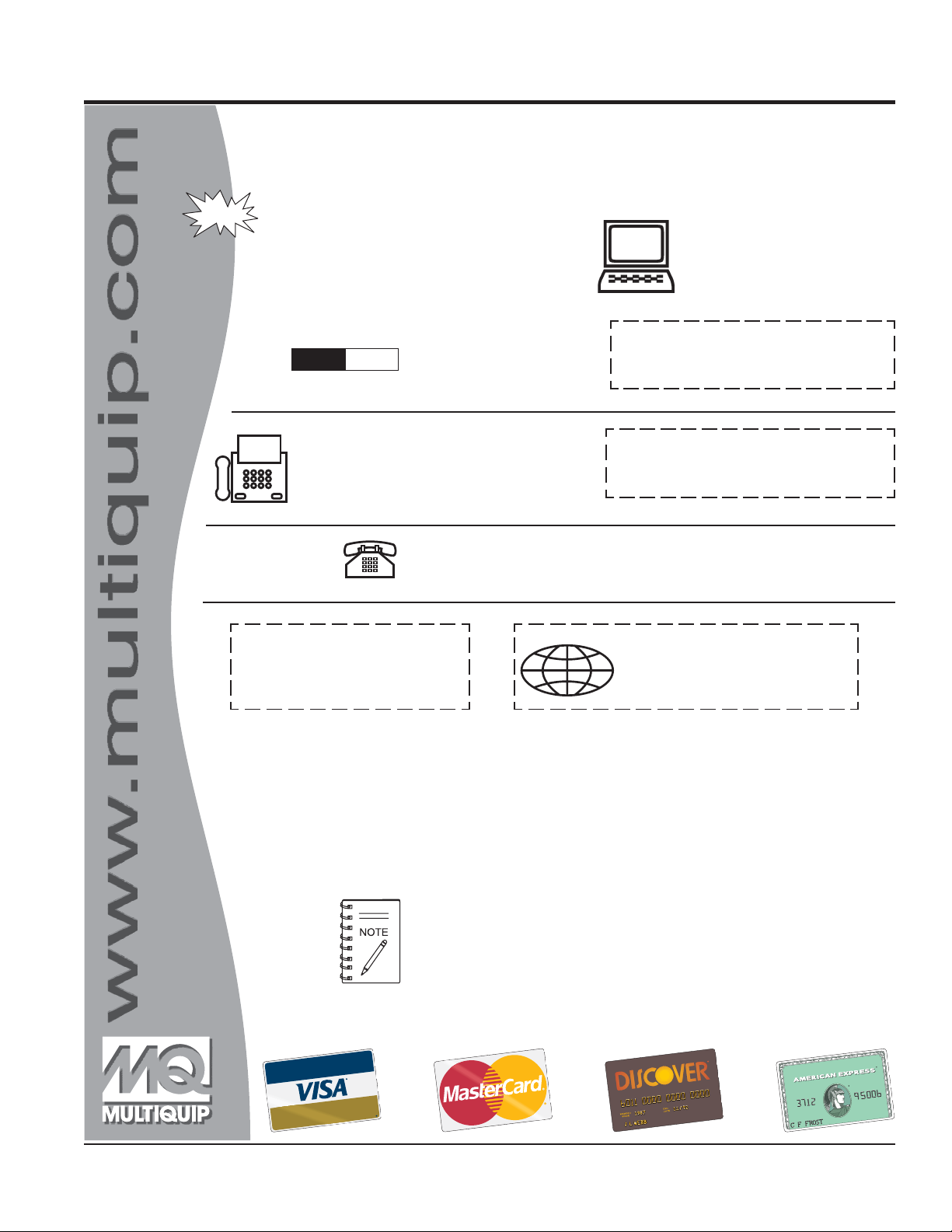
Ordering parts has never been easier!
Choose from three easy options:
Effective:
January 1
st
, 2006
Best Deal!
Order via Internet (Dealers Only):
Order parts on-line using Multiquip’s SmartEquip website!
■
View Parts Diagrams
■
Order Parts
■
Print Specification Information
Goto www.multiquip.com and click on
Order Parts
to log in and save!
Order via Fax (Dealers Only):
All customers are welcome to order parts via Fax.
Domestic (US) Customers dial:
1-800-6-PARTS-7 (800-672-7877)
Non-Dealer Customers:
Contact your local Multiquip Dealer for
parts or call 800-427-1244 for help in
locating a dealer near you.
Order via Phone:
If you have an MQ Account, to obtain a
Username and Password, E-mail us at:
parts@multiquip.com.
To obtain an MQ Account, contact your
District Sales Manager for more information.
internet
Use the
on
Standard orders
and qualify for a 5% Discount
for all orders which include
complete part numbers.*
Fax
your order in and qualify for a 2% Discount
on
Standard orders
for all orders which include
complete part numbers.*
Domestic (US) Dealers Call:
1-800-427-1244
International Customers
their local Multiquip Representatives for
Parts Ordering information.
Note: Discounts Are Subject To Change
Note: Discounts Are Subject To Change
should contact
❒❒
❒
❒❒
❒❒
❒
❒❒
❒❒
❒
❒❒
❒❒
❒
❒❒
❒❒
❒
❒❒
❒❒
❒
❒❒
www.multiquip.com
MVH120VGH • OPERATION AND PARTS MANUAL — REV. #2 (09/22/08) — PAGE 5
When ordering parts, please supply:
❒❒
❒
Dealer Account Number
Dealer Name and Address
Shipping Address (if different than billing address)
Return Fax Number
Applicable Model Number
Quantity, Part Number and Description of Each Part
All orders are treated as
and will ship the same day if received prior
to 3PM PST.
WE ACCEPT ALL MAJOR CREDIT CARDS!
❒❒
Standard Orders
Specify Preferred Method of Shipment:
✓
UPS/Fed Ex
■
Priority One
■
Ground
■ Next Day
■
Second/Third Day
✓ DHL
✓
Tr u c k
Page 6
SAFETY INFORMATION
Do not operate or service the equipment before reading
the entire manual. Safety precautions should be followed
at all times when operating this equipment.
Failure to readand understand the safety
messages and operating instructions could
result in injury to yourself and others.
SAFETY MESSAGES
The four safety messages shown below will inform you
about potential hazards that could injure you or others. The
safety messages specifically address the level of exposure
to the operator and are preceded by one of four words:
DANGER, WARNING, CAUTION or NOTICE.
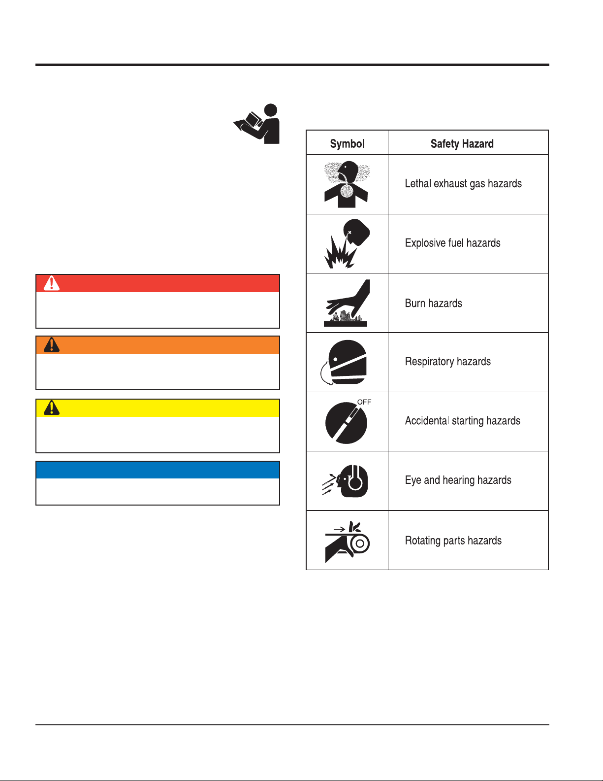
SAFETY SYMBOLS
DANGER
Indicates a hazardous situation which, if not avoided,
WILL result in DEATH or SERIOUS INJURY.
WARNING
Potential hazards associated with the operation of this
equipment will be referenced with hazard symbols which
may appear throughout this manual in conjunction with
safety messages.
Indicates a hazardous situation which, if not avoided,
COULD result in DEATH or SERIOUS INJURY.
CAUTION
Indicates a hazardous situation which, if not avoided,
COULD result in MINOR or MODERATE INJURY.
NOTICE
Addresses practices not related to personal injury.
PAGE 6 — MVH120VGH PLATE COMPACTOR • OPERATION AND PARTS MANUAL — REV. #2 (09/22/08)
Page 7
SAFETY INFORMATION
GENERAL SAFETY
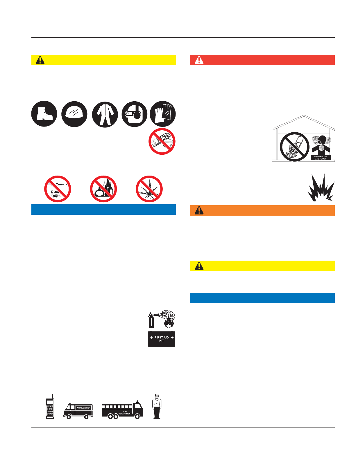
CAUTION
NEVER operate this equipment without proper protective
clothing, shatterproof glasses, respiratory protection,
hearing protection, steel-toed boots and other protective
devices required by the job or city and state regulations.
NEVER operate this equipment when not
feeling well due to fatigue, illness or when
under medication.
NEVER operate this equipment under the influence of
drugs or alcohol.
NOTICE
COMPACTOR SAFETY
DANGER
The engine fuel exhaust gases contain poisonous carbon
monoxide. This gas is colorless and odorless, and can
cause death if inhaled.
The engine of this equipment requires an adequate free
flow of cooling air. NEVER operate this equipment in any
enclosed or narrow area
where free flow of the air is
restricted. If the air flow is
restricted it will cause injury
to people and property and
serious damage to the
equipment or engine.
NEVER operate the equipment in an explosive
atmosphere or near combustible materials. An
explosion or fire could result causing severe
bodily harm or even death.
WARNING
This equipment should only be operated by trained and
qualified personnel 18 years of age and older.
Whenever necessary, replace nameplate, operation and
safety decals when they become difficult read.
Manufacturer does not assume responsibility for any
accident due to equipment modifications. Unauthorized
equipment modification will void all warranties.
NEVER use accessories or attachments that are not
recommended by Multiquip for this equipment. Damage
to the equipment and/or injury to user may result.
ALWAYS know the location of the nearest
fire extinguisher.
ALWAYS know the location of the nearest
first aid kit.
ALWAYS know the location of the nearest phone or keep
a phone on the job site. Also, know the phone numbers
of the nearest ambulance, doctor and fire department.
This information will be invaluable in the case of an
emergency.
NEVER disconnect any emergency or safety devices.
These devices are intended for operator safety.
Disconnection of these devices can cause severe injury,
bodily harm or even death. Disconnection of any of these
devices will void all warranties.
CAUTION
NEVER lubricate components or attempt service on a
running machine.
NOTICE
ALWAYS keep the machine in proper running condition.
Fix damage to machine and replace any broken parts
immediately.
ALWAYS store equipment properly when it is not being
used. Equipment should be stored in a clean, dry location
out of the reach of children and unauthorized personnel.
MVH120VGH • OPERATION AND PARTS MANUAL — REV. #2 (09/22/08) — PAGE 7
Page 8
SAFETY INFORMATION
ENGINE SAFETY
WARNING
DO NOT place hands or fingers inside engine
compartment when engine is running.
NEVER operate the engine with heat shields or
guards removed.
Keep fingers, hands hair and clothing away
from all moving parts to prevent injury.
DO NOT remove the radiator cap while the
engine is hot. High pressure boiling water will gush out
of the radiator and severely scald any persons in the
general area of the compactor.
DO NOT remove the coolant drain plug
while the engine is hot. Hot coolant will
gush out of the coolant tank and severely
scald any persons in the general area of
the compactor.
DO NOT remove the engine oil drain plug while the
engine is hot. Hot oil will gush out of the oil tank and
severely scald any persons in the general area of the
compactor.
CAUTION
FUEL SAFETY
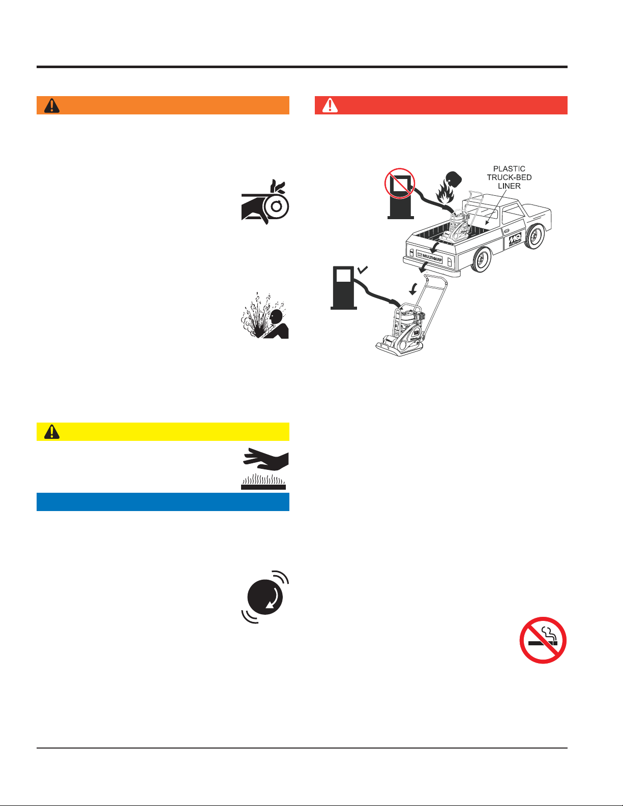
DANGER
DO NOT add fuel to equipment if it is placed inside truck
bed with plastic liner. Possibility exists of explosion or
fire due to static electricity.
FUEL
FUEL
DO NOT start the engine near spilled fuel or combustible
fluids. Diesel fuel is extremely flammable and its vapors
can cause an explosion if ignited.
ALWAYS refuel in a well-ventilated area, away from
sparks and open flames.
NEVER touch the hot exhaust manifold,
muffler or cylinder. Allow these parts to cool
before servicing equipment.
NOTICE
NEVER run engine without an air filter or with a dirty air
filter. Severe engine damage may occur. Service air filter
frequently to prevent engine malfunction.
NEVER tamper with the factory settings
of the engine or engine governor. Damage
to the engine or equipment can result
if operating in speed ranges above the
maximum allowable.
ALWAYS use extreme caution when working with
flammable liquids.
DO NOT fill the fuel tank while the engine is running
or hot.
DO NOT overfill tank, since spilled fuel could ignite if it
comes into contact with hot engine parts or sparks from
the ignition system.
Store fuel in appropriate containers, in well-ventilated
areas and away from sparks and flames.
NEVER use fuel as a cleaning agent.
DO NOT smoke around or near the
equipment. Fire or explosion could result
from fuel vapors or if fuel is spilled on a
hot engine.
PAGE 8 — MVH120VGH PLATE COMPACTOR • OPERATION AND PARTS MANUAL — REV. #2 (09/22/08)
Page 9
SAFETY INFORMATION
k
y
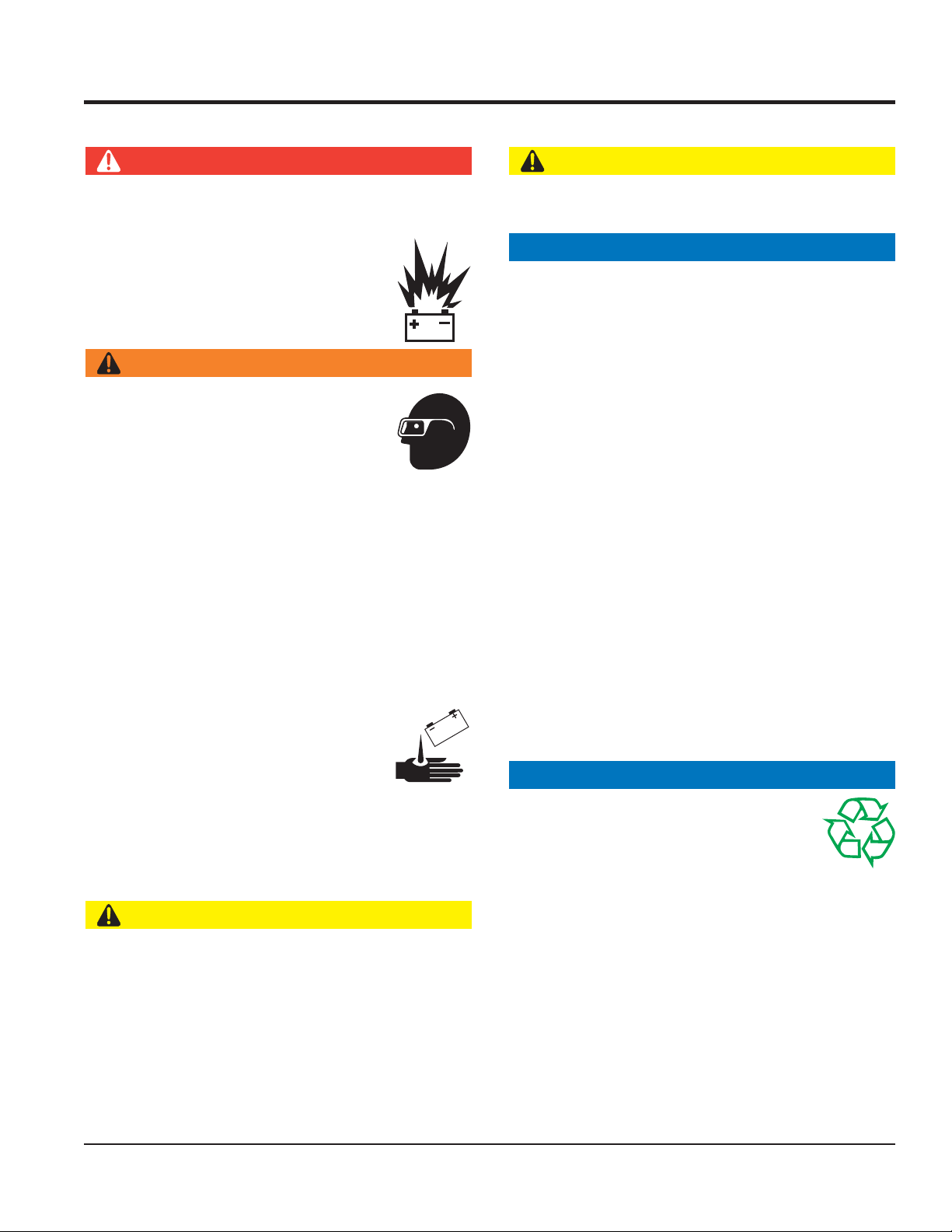
BATTERY SAFETY (ELECTRIC START ONLY)
DANGER
DO NOT drop the battery. There is a possibility that the
battery will explode.
DO NOT expose the battery to open flames,
sparks, cigarettes, etc. The battery contains
combustible gases and liquids. If these
gases and liquids come into contact with a
flame or spark, an explosion could occur.
WARNING
ALWAYS wear safety glasses when
handling the battery to avoid eye irritation.
The battery contains acids that can cause
injury to the eyes and skin.
Use well-insulated gloves when picking up
the battery.
ALWAYS keep the battery charged. If the battery is not
charged, combustible gas will build up.
TRANSPORTING SAFETY
CAUTION
NEVER allow any person or animal to stand underneath
the equipment while lifting.
NOTICE
Before lifting, make sure that the equipment parts (hoo
and vibration insulator) are not damaged and screws are
not loose or missing.
Always make sure crane or lifitng device has been
properly secured to the lifting bail (hook) of the
equipment.
ALWAYS shutdown engine before transporting.
NEVER lift the equipment while the engine is running.
Tighten fuel tank cap securely and close fuel cock to
prevent fuel from spilling.
Use adequate lifting cable (wire or rope) of sufficient
strength.
DO NOT charge battery if frozen. Battery can explode.
When frozen, warm the battery to at least 61°F (16°C).
ALWAYS recharge the battery in a well-ventilated
environment to avoid the risk of a dangerous concentration
of combustible gases.
If the battery liquid (dilute sulfuric acid)
comes into contact with clothing or skin,
rinse skin or clothing immediately with
plenty of water.
If the battery liquid (dilute sulfuric acid) comes into
contact with eyes, rinse eyes immediately with plenty
of water and contact the nearest doctor or hospital to
seek medical attention.
CAUTION
ALWAYS disconnect the NEGATIVE battery terminal
before performing service on the equipment.
ALWAYS keep battery cables in good working condition.
Repair or replace all worn cables.
Use one point suspension hook and lift straight
upwards.
DO NOT lift machine to unnecessary heights.
ALWAYS tie down equipment during transport b
securing the equipment with rope.
ENVIRONMENTAL SAFETY
NOTICE
Dispose of hazardous waste properly.
Examples of potentially hazardous waste
are used motor oil, fuel and fuel filters.
DO NOT use food or plastic containers to dispose of
hazardous waste.
DO NOT pour waste, oil or fuel directly onto the ground,
down a drain or into any water source.
MVH120VGH • OPERATION AND PARTS MANUAL — REV. #2 (09/22/08) — PAGE 9
Page 10

NOTES
PAGE 10 — MVH120VGH PLATE COMPACTOR • OPERATION AND PARTS MANUAL — REV. #2 (09/22/08)
Page 11

ecroFlagufirtneC )Nk5.22(fbl060,5
ycneuqerFnoitarbiV )zH001(mpv000,6
deepSgnilevarT )nim/m32ot0(nim/tf57ot0
)WxL(eziSetalP )mm004x585(ni8.51x32
noitcapmoCfoaerA.xaM )h/sretem.qs255(h/.tf.qs409,5
thgieWgnitarepO )gk811(.sbl062
yticapaCliOgnitarbiV )retil53.0(trauq73.0
SPECIFICATIONS
snoitacificepSHGV021-HVM.1elbaT
snoitacificepSenignE.2elbaT
ledoM 4XMS1U061XGADNOH
epyT
ekortSXeroB
tnemecalpsiD )cc361(.ni.uc01
tuptuOrewoPxaM .M.P.R0063@)WK3.5(PH1.7
yticapaCknaTleuF
leuF enilosaGelibomotuAdedaelnU
deepSgnitarepO mpr006,3
yticapaCliOebuL )sretil6.0(strauq36.0
dohteMgnitratS tratSlioceR
elcyc-4,delooc-riA
enignEenilosaG
1X.ni86.2
.ni77.
).mm54xmm86(
)sretil1.3(strauq3.3
MVH120VGH • OPERATION AND PARTS MANUAL — REV. #2 (09/22/08) — PAGE 11
Page 12
B
DIMENSIONS
A
E
C
D
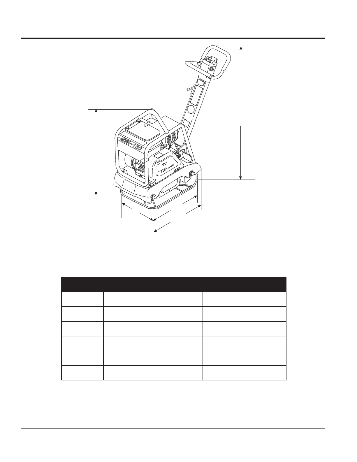
Figure 1. Compactor Dimensions
snoisnemiD.3elbaT
ecnerefeRnoitpircseDtnemerusaeM
A)noitisoPlacitreVnieldnaH(thgieH)mm081,1(ni5.64
BydoBniaMf
CetalPfothgneL)mm585(ni32
D)noitisoPlacitreVnieldnaH(htgneL)mm027(ni4.82
EetalPfohtdiW)mm0
othgieH)mm696(ni4.72
04(ni8.51
PAGE 12 — MVH120VGH PLATE COMPACTOR • OPERATION AND PARTS MANUAL — REV. #2 (09/22/08)
Page 13

GENERAL INFORMATION
DEFINITION OF PLATE COMPACTOR
The Mikasa MVH120VGH is a walk-behind, reversible plate
compactor designed for the compaction of sand and clay.
This plate compactor is a powerful compacting tool capable
of applying a tremendous force in consecutive high
frequency vibrations to a soil surface. Its applications include
soil compacting for road, embankments and reservoirs as
well as backfilling for gas pipelines, water pipelines and
cable installation work.
ECCENTRIC WEIGHTS
A set of rotating eccentric weights within the vibrator case
produces low amplitude high frequency vibrations, designed
to compact granular soil. The rotation of the weights are
controlled hydraulically through a lever on the control handle.
Changing the position of the lever allows smooth transition
between forward and reverse travel.
The resulting vibrations cause forward motion. The engine
and handle are vibration-isolated from the vibrating plate.
The heavier the plate, the more compaction force it
generates.
ANTI-VIBRATION HANDLE SYSTEM (AVT)
This compactor is equipped with advanced anti-vibration
handle design that reduces vibration to the operator by up
to 50% compared to other plate compactors.
FREQUENCY/SPEED
The compactor's vibrating plate has a frequency range of
6000 vpm (vibrations per minute). The forward and reverse
travel speed of the compactor is approximately 75 feet/
minute (23 meters/minute).
ENGINE
The plate compactor is equipped with a Honda
GX160U1SMX4 air-cooled, 4-cycle, gasoline engine.
MVH120VGH • OPERATION AND PARTS MANUAL — REV. #2 (09/22/08) — PAGE 13
Page 14
10
REVERSE
NEUTRAL
11
FORWARD
6
COMPONENTS
1
2
7
8
9
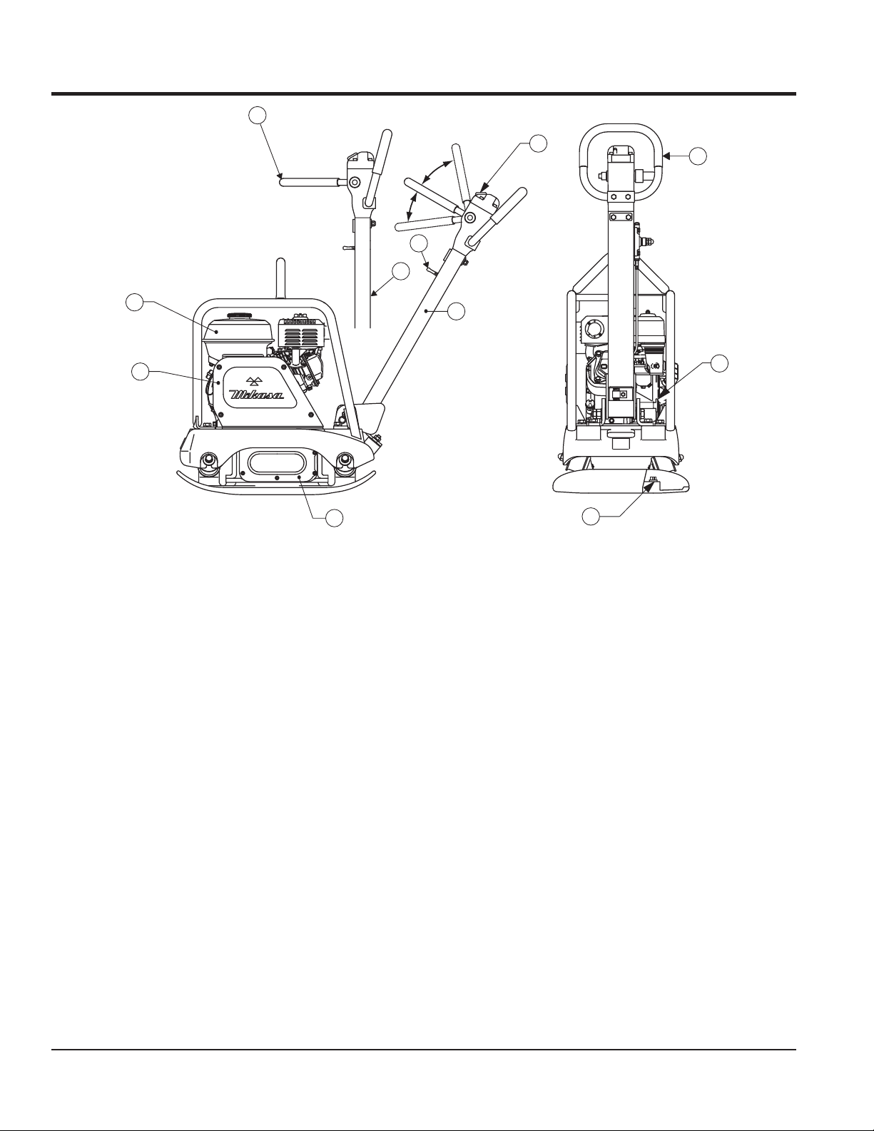
Figure 2. Compactor Components
5
Figure 2 shows the location of the controls, indicators and
general maintenance parts. The function of each control
is described below:
1. Breather Cap – Remove this cap to bleed (remove air)
the hydraulic system. When replacing hydraulic oil, use
"Shell Tellus #46" or equivalent.
7. Gasoline Engine – This plate compactor uses a
HONDA GX160 engine. Refer to the HONDA owner's
manual for engine information.
3
4
2. Hand Grip – When operating the compactor use this
hand grip to maneuver the compactor.
8. Belt Cover – Remove this cover to gain access to the
V-belts. NEVER run the compactor without the V-belt
cover. If the V-belt cover is not installed, your hand
3. Handle Lock – Pull handle bar downward (working
position), then pull handle lock to lock handle bar in
may get caught between the V-belt and clutch, thus
causing serious injury and bodily harm.
place.
9. Vibration Case – Encloses the eccentric gears and
4. Vibration Case Oil Level Check Plug – Remove this
counter weights.
plug to check the vibration case oil. Oil level should be
all the way up to the filler port. When replacing vibration
case oil, use 10W-30 engine oil.
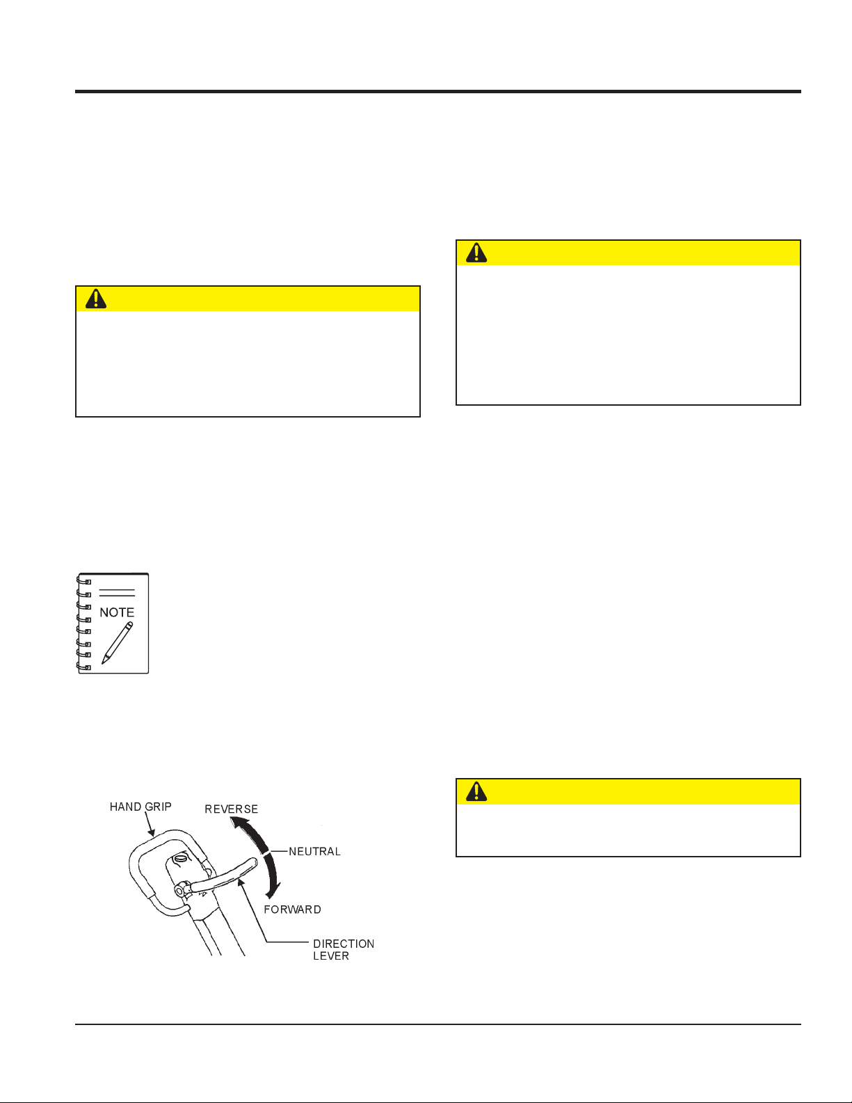
10. Forward & Reverse Lever –
the compactor will move in a forward direction.
Push
the lever forward,
the lever backwards, the compactor will move in
5. Handle Bar (working position) – When operating the
compactor, this handle is to be in the downward
backwards direction. Placing the lever in the middle
(midway) will cause the compactor not to move (neutral).
position.
11. Throttle Control – Move the throttle lever to the
6. Handle Bar (stored position) – When the compactor
is to be
stored
, move the handle bar to the upright
position for full throttle (max RPMs). For engine idle,
move the throttle lever to the
turtle
position.
position.
PAGE 14 — MVH120VGH PLATE COMPACTOR • OPERATION AND PARTS MANUAL — REV. #2 (09/22/08)
Pull
rabbit
Page 15
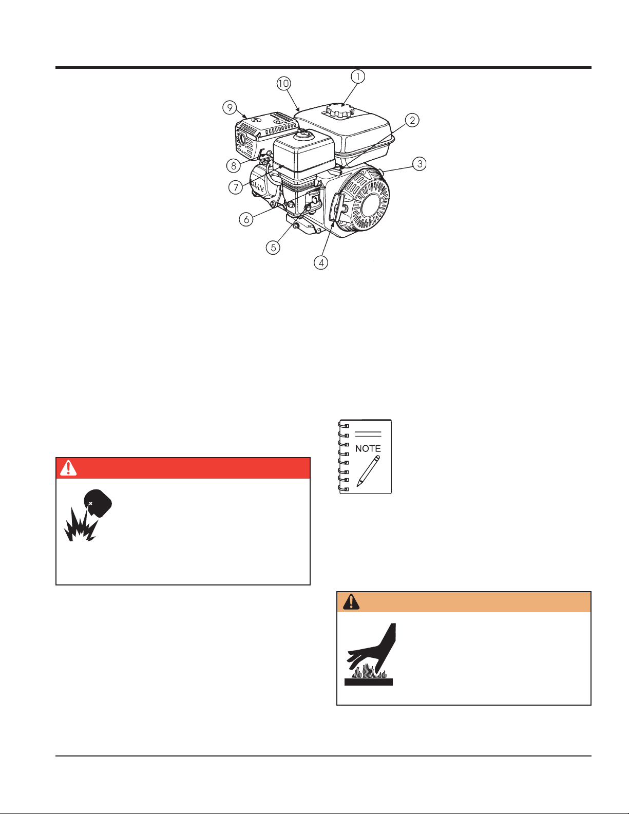
Figure 3. Compactor Components
The engine (Figure 3) must be checked for proper lubrication
and filled with fuel prior to operation. Refer to the
manufacturer's engine manual for instructions and details
of operation and servicing.
BASIC ENGINE
1. Fuel Filler Cap – Remove this cap to add unleaded
gasoline to the fuel tank. Make sure cap is tightened
securely. DO NOT over fill.
2. Throttle Lever – Used to adjust engine RPM speed
(lever advanced forwardoperator-
FAST
).
SLOW
, lever back toward
7. Air Cleaner – Prevents dirt and other debris from
DANGER — Fuel Hazard
Adding fuel to the tank should be done only
when the engine is stopped and has had
an opportunity to cool down. In the event
of a fuel spill, DO NOT attempt to start
the engine until the fuel residue has been
completely wiped up and the area surrounding the engine
is dry.
3. Engine ON/OFF Switch – ON position permits engine
starting, OFF position stops engine operation.
4. Recoil Starter (pull rope) – Manual-starting method.
Pull the starter grip until resistance is felt, then pull
briskly and smoothly.
5. Fuel Valve Lever – OPEN to let fuel flow, CLOSE to
stop the flow of fuel.
8. Spark Plug – Provides spark to the ignition system.
9. Muffler – Used to reduce noise and emissions.
entering the fuel system. Remove wing-nut on top of
air filter cannister to gain access to filter element.
Operating the engine without an air filter,
with a damaged air filter, or a filter in need
of replacement will allow dirt to enter the
engine, causing rapid engine wear.
Set spark plug gap to 0.024 - 0.028 inch (0.6 - 0.7 mm).
Clean spark plug once a week.
WARNING — Hot Components
Engine components can generate
extreme heat. To prevent burns, DO NOT
touch these areas while the engine is
running or immediately after operating.
NEVER operate the engine with the
muffler removed.
6. Choke Lever – Used in the starting of a cold engine,
or in cold weather conditions. The choke enriches the
fuel mixture.
MVH120VGH • OPERATION AND PARTS MANUAL — REV. #2 (09/22/08) — PAGE 15
10. Fuel Tank – Holds unleaded gasoline. For additional
information refer to engine owner's manual.
Page 16
INSPECTION
BEFORE STARTING
1. Read safety instructions at the beginning of manual.
2. Clean the compactor, removing dirt and dust.
Particularly, the bottom of the plate, engine cooling air
inlet, carburetor and air cleaner.
3. Check the air filter for dirt and dust. If the air filter is
dirty, blow through the air filter cartridge from the inside,
moving a jet of dry compressed air up and down until
all dust is removed. Otherwise replace air filter with a
new one.
4. Check carburetor for external dirt and dust. Clean with
dry compressed air.
5. Check fastening nuts and bolts for tightness. Loosened
screws or bolts due to vibration, could lead to
unexpected accident.
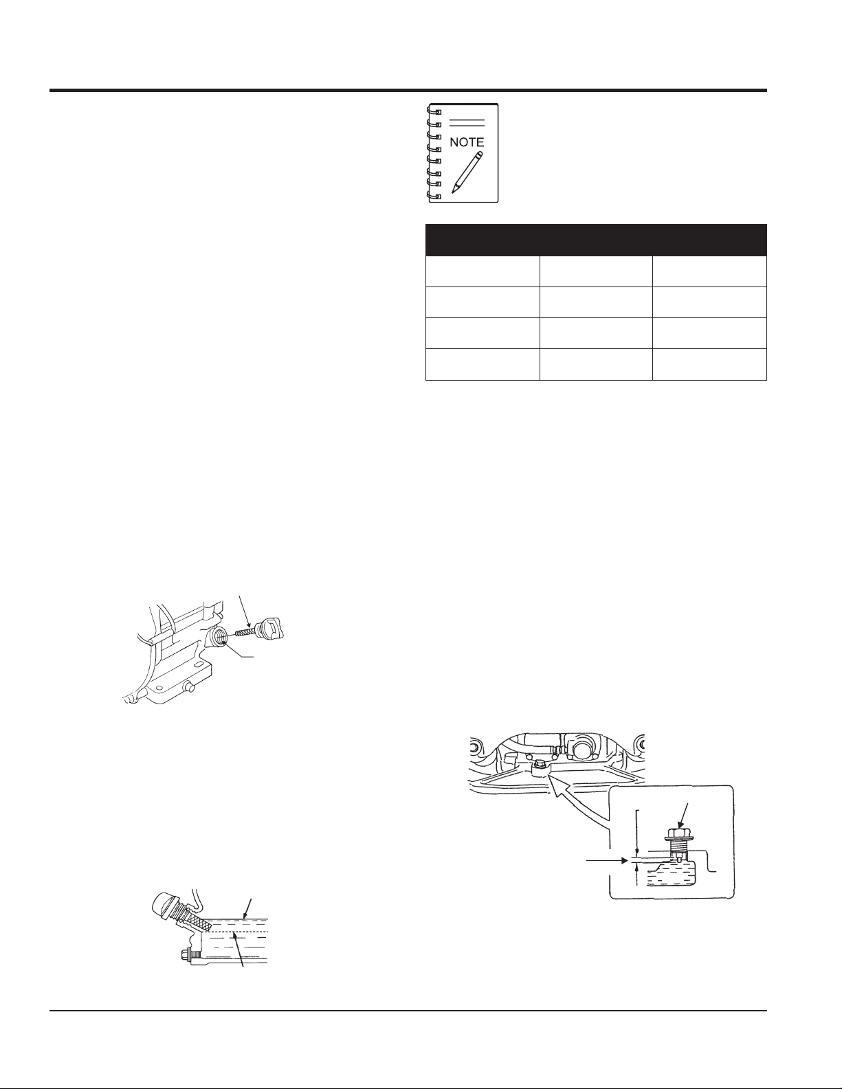
ENGINE OIL CHECK
1. To check the engine oil level, place the plate compactor
on secure level ground with the engine stopped.
2. Remove the filler cap/dipstick from the engine oil filler
hole (Figure 4) and wipe it clean.
GASOLINE CHECK
1. Remove the gasoline cap located on top of fuel tank.
2. Visually inspect to see if fuel level is low. If fuel is low,
3. When refueling, be sure to use a strainer for filtration.
VIBRATOR OIL CHECK
The Oil Alert system will automatically
stop the engine before the engine falls
below safe limits. Always be sure to check
the engine oil level prior to starting the
engine.
epyTliO.4elbaT
nosaeS erutarepmeT epyTliO
remmuS rehgiHroC°52 03-W01EAS
llaF/gnirpS C°01~C°52 02/03-W01EAS
retniW rewoLroC°0 01-W01EAS
replenish with unleaded fuel.
DO NOT top-off fuel. Wipe up any spilled fuel.
ENGINE OIL
DIPSTICK
1. Place the compactor horizontally on a flat surface.
2. Check vibrator oil level by removing bolt (vibrator oil
ENGINE OIL
FILLER HOLE
Figure 4. Engine Oil Dipstick
3. Insert and remove the dipstick without screwing it into
the filler neck. Check the oil level shown on the dipstick.
4. If the oil level is low (Figure 5), fill to the edge of the oil
filler hole with the recommended oil type (Table 4).
Maximum oil capacity is 0.63 quart.
UPPER LIMIT
LOWER LIMIT
gauge) as shown in Figure 6. Use a 14-mm wrench to
remove bolt. The vibrator oil level should be maintained
between the two markings as shown in Figure 6. If oil
is required, replace using SAE 10W-30.
OIL GAUGE
MAINTAIN OIL
LEVEL BETWEEN
LINES
OIL
Figure 6. Vibrator Oil Gauge
Figure 5. Engine Oil Level
PAGE 16 — MVH120VGH PLATE COMPACTOR • OPERATION AND PARTS MANUAL — REV. #2 (09/22/08)
Page 17
INSPECTION
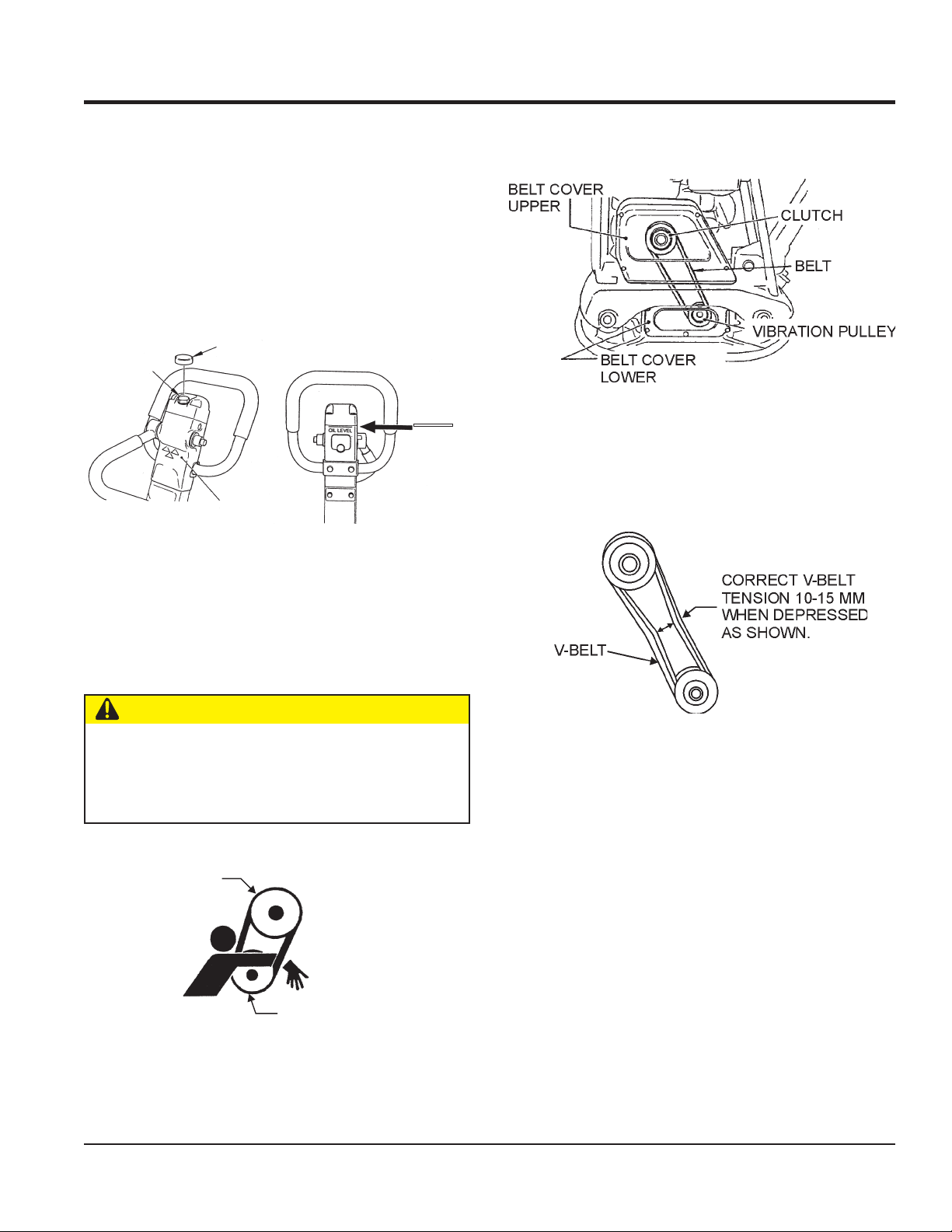
HYDRAULIC OIL CHECK
1. To check the V-belt tension (Figure 9), remove
1. With handle bar positioned vertically (storage position),
remove the breather cap (Figure 7) from the breather
plug.
2. Use a 24 mm wrench and remove breather plug
(Figure 7). Visually check to see if hydraulic oil comes
up to the oil level line that is etched on the back side
of the handle.
CAP
BREATHER
PLUG
OIL LEVEL
HAND PUMP
Figure 7. Hydraulic Oil Check
2. The V-belt tension is proper if the V-belt bends 10 to 15
upper
belt cover.
Figure 9. V-Belt Location
mm (Figure 10) when depressed with finger at midway
between the clutch and vibration pulley shafts.
3. If the hydraulic oil level is low, replace with "Shell
Tellus" oil #46 or equivalent.
V-BELT CHECK
CAUTION
Never attempt to check the V-belt with the engine running.
Severe injury can occur if your hand (Figure 8) gets
caught between the V-belt and clutch. Always use safety
gloves.
CLUTCH
PULLEY
VIBRATOR
PULLEY
Figure 10. V-Belt Tension
3. A loose V-belt will decrease the power transmission
output, causing reduced compaction and premature
wear of the belt. V-belt in use is RPF-3320 (A-32 is
also usable).
4. If the V-belt becomes worn or loose, replace it by using
V-belt part number RPF-3320 or A-32.
Figure 8. V-Belt Hazard
MVH120VGH • OPERATION AND PARTS MANUAL — REV. #2 (09/22/08) — PAGE 17
Page 18
OPERATION
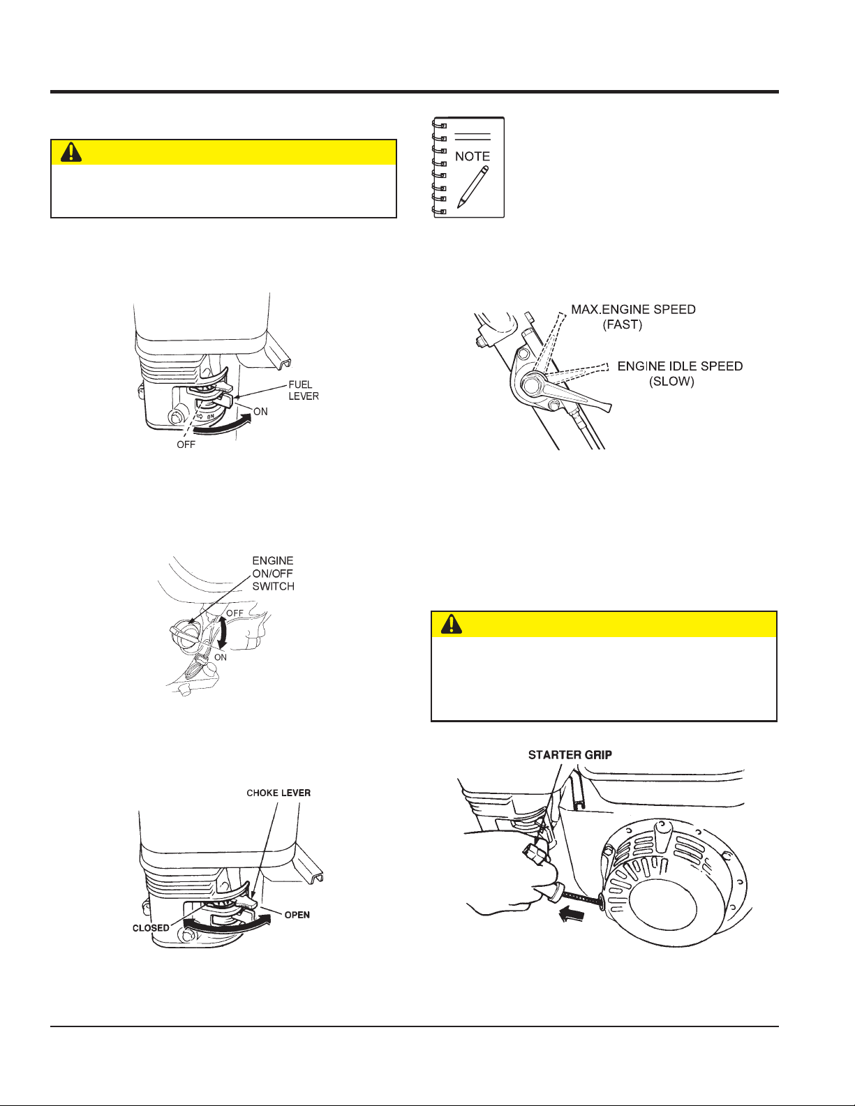
INITIAL STARTUP
CAUTION
DO NOT attempt to run the compactor until the safety
and initial startup sections have been read.
1. Place the
position.
2. Place the
"ON" position.
fuel valve lever
Figure 11. Fuel Valve Lever
Engine ON/OFF switch
(Figure 11) in the "ON"
(Figure 12) in the
The CLOSED position of the choke lever
enriches the fuel mixture for starting a
COLD engine. The OPEN position
provides the correct fuel mixture for
normal operation after starting and for
restarting a warm engine.
4. Place the
hydraulic pump, halfway between
5. Grasp the starter grip (Figure 15) and slowly pull it out.
The resistance becomes the hardest at a certain
position, corresponding the compression point. Rewind
the rope a little from that point and pull out sharply.
throttle lever
Figure 14. Engine Throttle Lever
(Figure 14), located near the
fast
and
slow
.
Figure 12. Engine ON/OFF Switch
3. Place the
position.
Choke Lever
(Figure 13) in the "OPEN"
Figure 13. Choke Lever
CAUTION
DO NOT pull the starter rope all the way to the end.
DO NOT release the starter rope after pulling. Allow it
to rewind as soon as possible.
Figure 15. Starter Grip
PAGE 18 — MVH120VGH PLATE COMPACTOR • OPERATION AND PARTS MANUAL — REV. #2 (09/22/08)
Page 19
OPERATION
6. If the engine has started, slowly return the choke lever
(Figure 12) to the
not started, repeat steps 1 through 5.
7. Before the compactor is put into operation, run the
engine for 3 to 5 minutes.
8. Check for abnormal engine noises or fuel leaks.
CLOSED
position. If the engine has
5. Firmly grasp the compactor's hand grip, the compactor
6. Slowly walk behind the compactor and be on the
OPERATION
Moving the direction lever back and forth a few times
CAUTION
Make sure to follow all safety rules referenced in the
safety section of this manual before operating the
compactor. Keep work area clear of debris and other
objects that could cause damage to the compactor
cause bodily harm.
1. Grasp the compactor's hand grip (Figure 15), and move
the engine throttle lever quickly from the
(idle) to the
2. Run the compactor at full throttle (3,600 RPM), the
centrifugal clutch will automatically engage when the
engine speed reaches 2,300 RPM.
rabbit position
Always move the throttle lever quickly
without hesitation because increasing the
engine speed slowly causes the clutch
to slip.
(full throttle) position.
turtle
position
after the engine has been turned off will cause the lever
to be locked in the forward position.
DO NOT operate the direction lever forcibly. The lever
will operate normally when the engine is started and
the compactor is in action.
.7. Compactor traveling speed may drop on soils which
Check the bottom plate to see if clay or similar material
has been lodged in the plate mechanism. If so, wash
with water and remove.
Keep in mind that the compactor does not work as
efficiently on clay or soils that have a high moisture
content level.
will begin moving in the desired position when the
direction lever has been placed in the desired position.
lookout for any large objects or foreign matter that
might cause damage to the compactor or bodily injury
CAUTION
contain clay, however there may be cases where
traveling speed drops because the compaction plate
does not leave the ground surface easily due to the
composition of the soil. To rectify this problem do the
following:
3. To make the compactor move in the forward direction
push the travel lever (Figure 15) forward.
4. To make the compactor move in the reverse direction
pull the travel lever (Figure 15) backwards.
Figure 16. Direction Lever
MVH120VGH • OPERATION AND PARTS MANUAL — REV. #2 (09/22/08) — PAGE 19
If the soil has a high moisture level, dry soil to
appropriate moisture content level or carry out
compaction twice.
STOPPING THE ENGINE
CAUTION
NEVER stop the engine suddenly while working at high
speeds.
1. Place the
and listen for the engine speed to decrease.
2. Place the
"OFF"
3. Place the
position.
throttle lever
(Figure 14) in
engine ON/OFF switch
position.
fuel valve lever
(Figure 11) in the
slow
position,
(Figure 12) in the
"OFF"
Page 20
MAINTENANCE
CAUTION
Inspection and other services should always be carried
out on solid and level ground with the engine shut down.
INSPECTION AND MAINTENANCE TABLES
1. To make sure your plate compactor is always in good
working condition before using, carry out the
maintenance inspection in accordance with Tables 5
and 6.
noitcepsnIenihcaM.5elbaT
METINOITAREPOFOSRUOH
swercSgnissiMroesooL)yadyreve(sruoh8yrevE
straPdegamaD)yadyre
gnillortnoCfonoitcnuF
traPmetsyS
kaeLmetsySciluardyHsruoh001yrevE
CliOrotarbiVsruoh001yrevE
kceh
tnemecalpeRliOrotarbiVsruoh003yrevE
ve(sruoh8yrevE
)yadyreve(sruoh8yrevE
kcehCenignE.6elbaT
metInoitarepOfosruoH
kcehCgulPkrapS)keewyreve(sruoh04yrevE
kaeLleuFroliO)yadyreve(sruoh8yrevE
fossenthgiT
sdaerhTgninetsaF
evE
dnakcehCliOenignE
tnemhsinelpeR
liOenignE
tnemecalpeR
elCevlaV
ecnara
)tsujdAdnakcehC(
gninaelCretliFriAsruoh001yrevE
)levelmumixam
sruoh001ot05
)yadyreve(sruoh8yrevE
)yadyreve(sruoh8yr
deificepsothsinelpeR(
raeyaecnorosruoh002
.kcehcenignenosliatedroflaunamenigneetarapeseeS
DAILY SERVICE
Check for leakage of fuel or oil.
Check for loose screws including tightness. See Table 7
(Tightening Torque) for retightening.
yrevenehtsruoh52tsrifretfA
yrevenehtsruoh52tsrifretfA
kcehCliOciluardyHsruoh001yrevE
liOciluardyH
tnemecalpeR
sruoh000,1yreve
neht,sruoh002retfatsriF
T4 07 051 003 005 057 001,1 004,1 000,2
kcehC)hctulc(tleb-Vsruoh002yrevE
T11 051 004 008 002,1 000,2 009,2 002,4 006,5
CAUTION
These inspection intervals are for operation under normal
* 001
conditions. Adjust your inspection intervals based on the
number of hours plate compactor is in use, and particular
working conditions.
Remove soil and clean the bottom of compaction plate.
CAUTION
Check hydraulic pump, piping and hose for any leakage.
lairetaM
mm6 mm8 mm01 mm21 mm41 mm61 mm81 mm02
T8-6 001 052 005 008 003,1 000,2 007,2 008,3
~003
~056
053
007
)munimulafositrapretnuocesacnI(*
ramsilairetamfoytilauqdnalairetaM
retemaiD
)mcgk(euqroTgninethgiT.7elbaT
)dednah-thgirllaeraenihcamsihthtiwesunisdaerhT(
A loosened hydraulic hose can be a cause for leakage.
Fuel piping and connections should be replaced every 2
years.
Check hydraulic hose connections with wrench applied
for tightness.
Check engine oil.
PAGE 20 — MVH120VGH PLATE COMPACTOR • OPERATION AND PARTS MANUAL — REV. #2 (09/22/08)
.wercsdnatlobhcaenodek
Page 21
MAINTENANCE
ENGINE OIL REPLACEMENT
1. Replace engine oil, in first 20 hours of operation and
every 100 hours afterwards.
2. Oil may be drained more easily when it is warm after
operation (For more details, see separate HONDA
Owner's Manual).
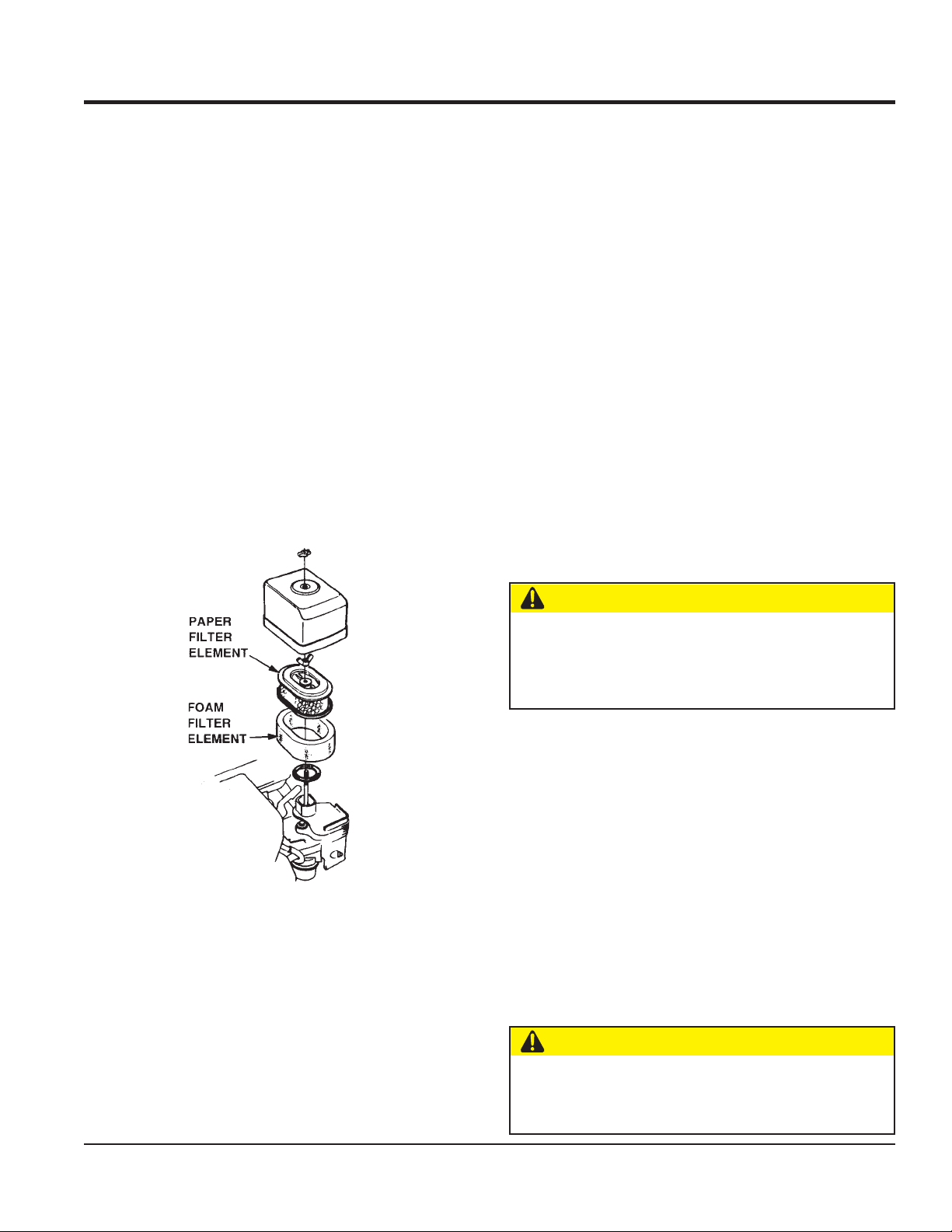
AIR FILTER
1. The air filter element should be cleaned because a
clogged air cleaner can cause poor engine starting,
lack of power and shorten engine life substantially.
2. To clean or replace air filter, loosen the wing nut on the
air filter housing (Figure 17). Remove the cover and
take out air filter cartridge. If only cleaning of the air
filter is desired, blow through the air filter cartridge from
the inside, moving a jet of dry compressed air up and
down until all dust is removed.
Replacing the V-belt
Remove the upper and lower belt covers. Engage an offset
wrench (13 mm) or the like to vibrator pulley (lower) fastening
bolt. Engage waste cloth or the like at midway of V-belt on
the left side and while pulling it back strongly, rotate the
offset wrench clockwise so that the V-belt will come off.
Reinstalling the V-belt
Engage V-belt to lower vibrator pulley and push the V-belt
to left side of upper clutch. In the same manner as in
removal, rotate offset wrench clockwise so that the V-belt
goes back on.
Checking Clutch
Check the clutch simultaneously with V-belt checking. With
belt removed, visually check outer drum of the clutch for
seizure and "V" groove for wear or damage. Clean the "V"
groove as necessary. Regularly check the lining or shoe
for wear. If the shoe is worn, power transmission becomes
deficient and slipping will result.
Whenever the compactor's vibration becomes weak or lost
during normal operation regardless of operation hours,
check the V-belt and clutch immediately.
VIBRATOR OIL LEVEL CHECK
1. In every 300 hours of operation, with the machine
Figure 17. Air Filter
2. In every 300 hours of operation, replace oil (capacity
CHECKING AND REPLACING V-BELT AND CLUTCH
1. After 200 hours of operation, remove the upper belt
cover to check the V-belt tension. Tension is proper if
the belt bends about 10 mm when depressed strongly
with finger between shafts. Loose or worn V-belts reduce
power transmission efficiency, causing weak
compaction and reducing the life of the belt itself.
Always clean the area around the vibrator oil level
check hole before removing oil check plug. This
will prevent dirt and debris from entering the system.
CAUTION
positioned horizontally, remove vibrator oil level check
plug (Figure 6) off vibrator (14 mm wrench) and see if
oil is up to filler port. Be sure to clean area around
check hole to prevent dirt and dust from entering.
400 cc). For draining oil through level check hole, have
the machine inclined with a sleeper or the like placed
under the compaction plate on opposite side.
* Use engine oil 10W-30 for this lubrication.
CAUTION
MVH120VGH • OPERATION AND PARTS MANUAL — REV. #2 (09/22/08) — PAGE 21
Page 22
MAINTENANCE
CAUTION
Make sure hydraulic oil in hand pump is at a normal
save operating level. DO NOT over fill. Over filling
(excessive oil) will cause excess oil to blow out of
breather plug.
HYDRAULIC OIL
Check hydraulic oil in every 100 hours of operation. With
handle bar positioned vertically (storage position), remove
breather plug (Figure 1) off the top of hydraulic pump and
check for proper oil level.
Replace hydraulic oil after first 200 hours and in every 1,000
hours of operation.
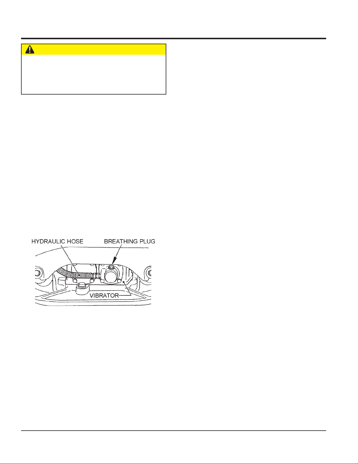
Replacing Hydraulic Oil
1. After removing plug cap of hand pump (Figure 7),
remove plug of breather (24 mm wrench) and disconnect
vibrator side of hydraulic hose (Figure 18) at vibrator
cylinder. With travel lever placed in the
position, drain hydraulic oil in the pump.
FORWARD
STORAGE
For storage of the pump for over 30 days, the following is
required:
Drain the fuel tank completely.
Run the engine until the fuel in the injection system is
completely consumed.
Completely drain the oil from the engine crankcase and
follow procedures described in the HONDA engine
Owner's Manual for engine storage.
Completely drain the compactor's hydraulic oil from the
vibrating case.
Clean entire plate compactor, especially the bottom plate,
removing all dirt and foreign matter.
Cover plate compactor and engine with plastic covering
or equivalent and store in a clean, dry place.
2. After draining, reconnect the hydraulic hose to vibrator.
Figure 18. Hydraulic Hose
3. Fill oil through breather hole of hand pump. (capacity:
about 300 cc). Use
4. Removing breather plug at vibrator cylinder causes oil
to flow out of breather hole in a while. When aeration
disappears, replace the plug and tighten securely.
5. Replace breather plug of hand pump and fit the plug
cap. After making sure that oil in pump is at proper
level, replace the breather plug.
Shell Tellus Oil #46
or equivalent.
PAGE 22 — MVH120VGH PLATE COMPACTOR • OPERATION AND PARTS MANUAL — REV. #2 (09/22/08)
Page 23

TROUBLESHOOTING
gnitoohselbuorTenignE.8elbaT
motpmySesuaCelbissoPnoituloS
?gnigdirbgulpkrapS .gulpkrapsecalperronoitalusni,pagkcehC
sileuf",tratsottluciffiD
taKRAPSontub,elbaliava
"gulpkraps
.
sileuf",tratsottluciffiD
siKRAPSdna,elbaliava
."gulpkrapsehttatneserp
fiD
sileuf",tratsottlucif
dnatneserpsikraps,elbaliava
"lamronsinoisserpmoc
?yrtrid
?gnitiucric
?noitalusnigulpkraps
ggulpkrapsreporpmI.pagreporpotteS
?evitcefedliocnoitingI.liocnoitingiecalpeR
gkrapsreporpmI
?gnitiucrictrohs
?epytleufgnorW
?ytridrenaelcriA.renaelcriaecalperronaelC
?gulpkrapsnotisopednobraC.gulpkrapse
tneicifedoteudtiucrictrohS
?pa
?d
etrohssihctiwsFFO/NO.hctiwsecalper,gniriwhctiwskcehC
stniop,pa
ronrownoitalusniresnednoC
trohsronekorberiwgulpkrapS
?metsysleufnitsudroretaW.metsysleufhsulF
calperronaelC
.nrowfiecalper,noitalusnigulpkrapskcehC
.stniopnaelcdnapagkrapstcerrocteS
dnocecalpeR
.resne
.gniriwgulpkrapsevitcefedecalpeR
tcerrochtiwecalperdna,metsysleufhsulF
.leuffoepyt
rokcutsevlavtsuahxe/noitcuS
?dedurtorp
rednilycro/dnagnirnotsiP
tsottluciffiD
"wolsinoisserpmoc
sileuf",tra
dnatneserpsikraps,elbaliava
.roterubractatneserpleufoN
?nrow
gulpkrapsro/dnadaehrednilyC
pdenethgitton
?ylreporp
?deggolc
?enilleufniriA.enilleufdeelB
?ylrepor
gulpkrapsro/dnateksagdaeH
?degamadteksag
?knatleufnielbaliavatonleuF.leuffoepyttcerrochtiwlliF
nepot
onseodkcocleuF
?deggolcretlifleuF.retli
elohrehtaerbpacknatleuF
taes-eR
.sevlav
.notsiprodnasgnirnotsipecalpeR
.gulpkrapsdnastlobdaehrednilyceuqroT
rapsdnadaehecalpeR
.yrassecenfiecalper
fleufecalpeR
.packnatleufecalperronaelC
.steksaggulpk
,revelkcocleufnesoolottnacirbulylppA
MVH120VGH • OPERATION AND PARTS MANUAL — REV. #2 (09/22/08) — PAGE 23
Page 24

TROUBLESHOOTING
)deunitnoc(gnitoohselbuorTenignE.8elbaT
motpmySesuaCelbissoPnoituloS
?naelctonrenaelcriArenaelcriaecalperronaelC
"rewopnikaeW"
reporpsinoisserpmoc
fsimtonseoddna
.eri
?roterubracnilevelreporpmI .roterubracdliuber,
?gulpkrapSevitcefeD.gulpkrapsecalperronaelC
tnemtsujdataolfkcehC
"rewopnikaeW"
reporpsinoisserpmoc
imtub
.serifs
?reporpmi
.staehrevoenignE
deepslanoitatoR
.setautculf
retratslioceR
.noitcnuflam
?triddnatsud
?metsysleufniretaW
?gulpkrapsytriD.gulpkrapsecalpe
?evitcefedliocnoitingI.liocnoitingiecalpeR
eulavtaehgulpkrapS
?leuffoepyttcerroCleuffoepyttcerrochtiwecalpeR
?ytridsnifgnilooC.snifgniloocnae
?yltcerrocdetsujdaronrevoG.ronrevogtsujdA
?evitcefedgnirpsronrevoG.gnirpsron
?detcirtserwolfleuF .sgolcroskaelrofmetsysleuferitnekcehC
olcmsinahcemlioceR
?esoolgnirpslaripS.gnirpslaripsecalp
htiwdegg
.leuf
rronaelC
sfoepyttcerrochtiwecalpeR
lC
revogecalpeR
eR
.gulpkrap
.retawdnapaoshtiwylbmessaliocernaelC
foepyttcerrochtiwecalperdna,metsysleufhsulF
PAGE 24 — MVH120VGH PLATE COMPACTOR • OPERATION AND PARTS MANUAL — REV. #2 (09/22/08)
Page 25

TROUBLESHOOTING
gnitoohselbuorTrotcapmoC.9elbaT
motpmySesuaCelbissoPnoituloS
?spilshctulC.h
ctulcecalperrotsujdA
?spilstleb-V.tleb-VecalperrotsujdA
?rotarbivniliOevissecxE..leveltcerrocotlliF
dnawoldeepslevarT
etnirotarbivnielbuorT
.kaewnoitarbiv
?slanr
ynaecalper,strapevitcefedro
nrowynarofylbmessarotarbivkcehC
.strapevitcefed
ofrofliociluardyhninoitareA
?.etsysgnisrever
?tcerrocnideepsenignE .MP
erlevarT.metsyslevarteritnekcehC
levartr
)gulpdeelB(.liociluardyhniriaegruP
RtcerrocotdeepsenigneteS
?.evitareponimetsysgnisrev
?tcerrocnoitallatsnirevelgnisreveR .revelgnisreverfonoitallatsninaelC
?e
sohlioevitcefedronekorB.esohlioecalpeR
drawkcabrodrawrofslevarT
hctiwsotelbanutub
?.etsysgnisrever
levartrofrofliociluardyhninoitareA
ociluardyhniriaegruP
)gulpdeelB(.li
.noitcerid
?metsysgnisrevernilioevissecxE..leveltcerrocotlliF
?hsarthtiwdeggolcevlavrotceleS.ev
?eruliafgniraebnotsiprednilyC
lavrotcelesnaelC
rofrednilycnigniraebnotsipkcehC
.gnikcapHSUtaegakael
?spilsrodegagne-sidtleb-V .ecalperrotsujda,tleb-VegagnE
?spilshctulC .yrassec
wrofnilevarttonseoD
.esrever
.taerg
rodra
?degamadyaw
ruliafgniraebnotsiprednilyC
ecnatsisergnitareporevelgnisreveR
?liociluardyhevissecxE .leveltcerrocotlliF
-yekretpadaroyektahstupnipmuP
yaw
?e
enfiecalper,hctulctsujdA
-yekretpadaroyektahstupniecalpeR
rofrednilycnigniraebnotsipkcehC
.gnikcapHSUtaegakael
MVH120VGH • OPERATION AND PARTS MANUAL — REV. #2 (09/22/08) — PAGE 25
Page 26

EXPLANATION OF CODE IN REMARKS COLUMN
The following section explains the different symbols and
remarks used in the Parts section of this manual. Use the help
numbers found on the back page of the manual if there are any
questions.
The contents and part numbers listed in the parts section are
subject to change
guarantee the availability of the parts listed.
Sample Parts List:
NO. PART NO. PART NAME QTY. REMARKS
1 12345 BOLT ...................... 1 ......INCLUDES ITEMS W/
2
*
2*12347 WASHER, 3/8 IN. ... 1 ......
3 12348 HOSE ................... A/R ....MAKE LOCALLY
4 12349 BEARING ............... 1 ......S/N 2345B AND ABOVE
NO. Column
Unique Symbols - All items with same unique symbol
(
, #, +, %, or >) in the number column belong to the same
*
assembly or kit, which is indicated by a note in the “Remarks”
column.
Duplicate Item Numbers - Duplicate numbers indicate
multiple part numbers are in effect for the same general
item, such as different size saw blade guards in use or a
part that has been updated on newer versions of the same
machine.
When ordering a part that has more than one
item number listed, check the remarks column
for help in determining the proper part to order.
without notice
WASHER, 1/4 IN. .............
. Multiquip does not
NOT SOLD SEPARATELY
MQ-45T ONLY
*
QTY. Column
Numbers Used - Item quantity can be indicated by a
number, a blank entry, or A/R.
A/R (As Required) is generally used for hoses or other parts
that are sold in bulk and cut to length.
A blank entry generally indicates that the item is not sold
separately. Other entries will be clarified in the “Remarks”
Column.
REMARKS Column
Some of the most common notes found in the “Remarks”
Column are listed below. Other additional notes needed to
describe the item can also be shown.
Assembly/Kit
unique symbol will be included when this item is purchased.
Indicated by:
“INCLUDES ITEMS W/(unique symbol)”
Serial Number Break
number range where a particular part is used.
Indicated by:
“S/N XXXXX AND BELOW”
“S/N XXXX AND ABOVE”
“S/N XXXX TO S/N XXX”
Specific Model Number Use
used only with the specific model number or model number
variant listed. It can also be used to show a part is NOT
used on a specific model or model number variant.
Indicated by:
“XXXXX ONLY”
“NOT USED ON XXXX”
- All items on the parts list with the same
- Used to list an effective serial
- Indicates that the part is
“Make/Obtain Locally”
PART NO. Column
Numbers Used - Part numbers can be indicated by a
number, a blank entry, or TBD.
TBD (To Be Determined) is generally used to show a part
PAGE 26 — MVH120VGH PLATE COMPACTOR • OPERATION AND PARTS MANUAL — REV. #2 (09/22/08)
purchased at any hardware shop or made out of available
items. Examples include battery cables, shims, and certain
washers and nuts.
“Not Sold Separately”
purchased as a separate item and is either part of an
- Indicates that the part can be
- Indicates that an item cannot be
Page 27

SUGGESTED SPARE PARTS
MVH120VGH PLATE COMPACTOR WITH HONDA GX160U1SMX4 ENGINE
1 to 3 units
QTY. P/N DESCRIPTION
4 ......... 458450620 .................. SHOCK ABSORBER
3 ......... 070100322 .................. V-BELT
1 ......... 956100041 .................. THROTTLE WIRE
3 ......... 9807955846 ................ SPARK PLUG
1 ......... 28462ZH8003 ............. ROPE, RECOIL STARTER
3 ......... 17218ZE1505 ............. FILTER, OUTER, AIR
1 ......... 17620Z44000 .............. CAP COMP, FUEL TANK (CHROME) (S/N 1125015 AND ABOVE)
3 ......... 17672Z4H000 ............. FILTER, FUEL
MVH120VGH • OPERATION AND PARTS MANUAL — REV. #2 (09/22/08) — PAGE 27
Page 28

NAMEPLATE AND DECALS
8
MVH-120
7
9
1
3
SHELL TELLUS OIL
46
2
N
3
P
3
A
-
3
OPERATIONAL CAUTION
Prior to OPERATION:
Check engine oil and fuel level
if not enough, add to proper level
To START engine:
1. Warm up engine at low speed for 3
to 5 minutes.
2. Operate machine always at full speed
to avoid incorrect clutch engagement.
3. Use travel lever for forward and reverse
10
CAUTION
ATTENZIONE
ATENÇAÕ
* Read operator’s manual carefully before use.
* Libre le manual attentivement avant utillsation.
* Bitte lesen Sie vor inbetriebnahme der Maschine de
Bedienungsanleitung sogfältig durch.
* Prima dell’uso leggere attentamente il manuale.
* Lee com atenÇão o manual de instruÇões antes de
usar.
* Leer detenidamente el mamual de instrucciones
antes de usar la maquina.
PRECAUCION
NPA-769 J
motion. Do not push or pull lever strongly.
To STOPengine:
Move stop switch to “OFF” position.
To LIFTmachine by using lifting hook in center
To STOREmachine covered with plastic
sheet in a moisture.
Do not move travel lever
if engine stops
NPA-748
J
SAE 10W-30
MOTOR OIL
NPA-195
J
6
Serial No.
Model No.
CONTACT
PARTS DEPT.
5
V BELT RPF-3320
NPA-742
J
NPA-743
J
4
PAGE 28 — MVH120VGH PLATE COMPACTOR • OPERATION AND PARTS MANUAL — REV. #2 (09/22/08)
Page 29

NAMEPLATE AND DECALS
NO PART NO PART NAME QTY. REMARKS
1 920207480 DECAL, SHELL TELLUS OIL 46 ................ 1 ................ NPA-748
2 920207430 DECAL, CAUTION ...................................... 1 ................ NPA-743
3 920203330 EAR PROTECTION LABEL........................ 1 ................ DCL333
4 920201580 DECAL, MQ MARK 71X55 1
5 920207420 DECAL, V-BELT RPF-3320 .........................1 ................NPA-742
6 PLATE, SERIAL NO ................................... 1 ................ CONTACT MQ PARTS DEPT.
7 920201950 DECAL, OIL SAE 10W-30 ......................... 1 ................ NPA-195
8 920207440 DECAL, MODEL, MVH-120 1
9 920207400 DECAL, DANGER-CAUTION 1
10 920207690 DECAL, CAUTION(MANUAL) ..................... 1 ................ NPA-769
MVH120VGH • OPERATION AND PARTS MANUAL — REV. #2 (09/22/08) — PAGE 29
Page 30

VIBRATING PLATE ASSY.
5
6
7
2
2
7
6
5
10
9
11
1
4
3
4
11
(For Belt adjustment)
PAGE 30 — MVH120VGH PLATE COMPACTOR • OPERATION AND PARTS MANUAL — REV. #2 (09/22/08)
Page 31

VIBRATING PLATE ASSY.
NO PART NO PART NAME QTY. REMARKS
1 458115140 VIBRATING PLATE 1
2 458450620 SHOCK ABSORBER MED55 M12 4
3 020312100 NUT M12 4
4 030212300 WASHER, LOCK M12 4
5 022131210 CAP NUT M12 4
6 030212300 WASHER, LOCK M12 4
7 952405600 WASHER 12.5X35X4.5 4
9 460449160 OIL GAUGE 1
10 953405260 PACKING 1/4 (CU) 1
11 952401190 WASHER 13X43X4.5 4
MVH120VGH • OPERATION AND PARTS MANUAL — REV. #2 (09/22/08) — PAGE 31
Page 32

37
39
36
BODY ASSY.
35
61
51
52
54
53
64
38
40
63
62
63
52
53
60
15
12-1
12-2
12-3
12-4
12-6
12-7
12-8
20
6
12
11
13
14
8
7
16
21
19
18
17
3
4
5
2
47
48
46
45
44
44
41
43
42
41
1
44
43
PAGE 32 — MVH120VGH PLATE COMPACTOR • OPERATION AND PARTS MANUAL — REV. #2 (09/22/08)
Page 33

BODY ASSY.
NO PART NO PART NAME QTY. REMARKS
1 458119620 BASE 1
2 912216010 ENGINE AY GX160U1 1
3 001220835 BOLT 8X35 T 4
4 030208200 WASHER, LOCK M8 4
5 031108160 WASHER, FLAT M8 4
6 458214380 BELT COVER PLATE 1
7 001220820 BOLT 8X20 T 4
8 030208200 WASHER, LOCK M8 4
11 458451370 SPACER 202512 1
12 458337770 CLUTCH ASSY A112420 ............................ 1................ INCLUDES ITEMS W/
12-1*941040510 CLUTCH SHAFT S20D45 1
12-2*941010390 CLUTCH PULLEY A1124 1
12-3*941020030 CLUTCH SHOE T90T 3
12-4*941030230 CLUTCH SPRING 2
12-6*080200300 STOP RING S30 1
12-7*080600550 STOP RING AR55 1
12-8*046006006 BEARING 6006DDU 1
13 0320050150 KEY 1
14 458451380 CLUTCH WASHER 1
15 001520825 SOCKET HEAD BOLT 8X25 T 1
16 070100322 VBELT RPF3320 1
17 458214390 DUST COVER 1
18 092006010 FLAT HEAD SCREW 6X10 2
19 458337560 SPONGE, DUST COVER 1
20 458115190 BELT COVER 1
21 001520852 SOCKET HEAD BOLT 8X60 T 4
35 458450830 RUBBER COVER 1
36 458450810 PLATE, RUBBER COVER 1
37 001220825 BOLT 8X25 T 2
38 030208200 WASHER, LOCK M8 2
39 031108160 WASHER, FLAT M8 2
40 022710809 NYLON NUT M8 2
41 15550ZK8P90 DRAIN JOINT 2
42 15552ZB9000 DRAIN HOSE 1
43 954010070 HOSE BAND 11.5D 2
44 90601ZE1000 WASHER, DRAIN PLUG 3
45 90131ZE1000 BOLT, DRAIN PLUG 1
46 458450840 JOINT 1
47 001220820 BOLT 8X20 T 1
48 030208200 WASHER, LOCK M8 1
51 458119650 GUARDFRAME(GX160) /120V 1
52 001221235 BOLT 12X35 T 2
53 030212300 WASHER, LOCK M12 4
54 001221225 BOLT 12X25 T 2
60 930103521 SHOCK ABSORBER ME35 15X15 1
61 458347660 LOCK LEVER 1
62 030208200 WASHER, LOCK M8 1
63 020408050 NUT M8, H=5 2
64 001520830 SOCKET HEAD BOLT 8X30 T 1
*
MVH120VGH • OPERATION AND PARTS MANUAL — REV. #2 (09/22/08) — PAGE 33
Page 34

22
19
32
33
27
23
28
24
9
18
29
21
34
26
2
19
31
18
48
VIBRATOR ASSY.
A
30
5
5
6
3
2
41
42
9
19
16
19
18
15
12
14
18
4
40
42
43
13
36
5
2
1
17
11
2
5
43
35
37
39
38
20
25
45
46
PAGE 34 — MVH120VGH PLATE COMPACTOR • OPERATION AND PARTS MANUAL — REV. #2 (09/22/08)
Page 35

VIBRATOR ASSY.
NO PART NO PART NAME QTY. REMARKS
A 458910011 VIBRATOR ASSY ....................................... 1 ................ INCLUDES ITEMS W/ #
1# 458115150 VIBRATING CASE 1
2# 040406307 BEARING 6307C4 4
3# 458337700 ROTARY SHAFT, DRIVE 1
4# 458342580 ROTARY SHAFT, DRIVEN/NEW 1
5# 080200350 STOP RING S35 8
6# 951405460 KEY 10X8X19 RR 1
9# 040306907 BEARING 6907C3 2
11# 458337730 PISTON ROD 1
12# 025508050 PIN 8X50 1
13# 042506000 BEARING 6000ZZSG 2
14# 080200100 STOP RING S10 1
15# 455435051 PISTON, 22.4D 1
16# 455010070 PACKING USH22.4X30X5 1
17# 080100260 STOP RING R26 1
18# 458451430 ECCENTRIC ROTATOR 4
19# 009120304 SOCKET HEAD BOLT 10X25 T 4
20# 060202040 OIL SEAL SC28458 1
21# 458337740 BEARING COVER 1
22# 001220820 BOLT 8X20 T 4
23# 030208200 WASHER, LOCK M8 4
24# 031108160 WASHER, FLAT M8 4
25# 953405580 SEAL CAP SC458 1
26# 458214370 CYLINDER 1
27# 001220820 BOLT 8X20 T 4
28# 030208200 WASHER, LOCK M8 4
29# 031108160 WASHER, FLAT M8 4
30# 460333002 GEAR (DRIVE) 2P 1
31# 458342590 GEAR (DRIVEN) 1
32# 001200812 BOLT 8X12 1
33# 953404600 COPPER PACKING 8X16X2 1
34# 954010020 CONNECTOR PT, PF1/4 1
35 458337750 PULLEY 80D 1
36# 951400990 KEY 7X7X20 1
37 952400690 WASHER 9X35X4.5 1
38 001220820 BOLT 8X20 T 1
39 030208200 WASHER, LOCK M8 1
40# 001221240 BOLT 12X40 T 2
41 001221264 BOLT 12X120 T 6
42 030212300 WASHER, LOCK M12 8
43 031112230 WASHER, FLAT M12 8
45 460212740 BELT COVER (LOWER) 1
46 001520635 SOCKET HEAD BOLT 6X35 T 5
48# 952406180 SHIM 70800.2T 1
MVH120VGH • OPERATION AND PARTS MANUAL — REV. #2 (09/22/08) — PAGE 35
Page 36

CONTROL ASSY.
PAGE 36 — MVH120VGH PLATE COMPACTOR • OPERATION AND PARTS MANUAL — REV. #2 (09/22/08)
Page 37

CONTROL ASSY.
NO PART NO PART NAME QTY. REMARKS
1 458119640 HANDLE VAS/ MVH-120,150
7 031110160 WASHER, FLAT M10 1
8 939010320 STOPPER RUBBER 45X36H 1
9 020410060 NUT M10, H=6 1
10 030210250 WASHER, LOCK M10 1
11 458338001 PUMP ASSY 1
12 458337430 TRAVEL LEVER 1
13 001520820 SOCKET HEAD BOLT 8X20 T 2
14 458451420 COLLAR 1
15 033910030 WAVE WASHER 15.5X20X0.3 4
17 022710809 NYLON NUT M8 2
18 030208200 WASHER, LOCK M8 2
19 954002850 OIL HOSE 985L 1
20 954404230 CLAMP SA12018 1
21 001220625 BOLT 6X25 T 1
22 020306050 NUT M6 1
23 030206150 WASHER, LOCK M6 1
24 031106100 WASHER, FLAT M6 1
28 458451630 BREATHER CAP 1
29 458347640 HANDLE BRACKET, L 1
30 458347650 HANDLE BRACKET, R 1
31 458461430 LOCK CATCH 1
32 009120408 SUNK HEAD BOLT 8X20 T 3
35 001221230 BOLT 12X30 T 2
36 030212300 WASHER, LOCK M12 2
40 458217830 HANDLE GRIP 1
41 001220825 BOLT 8X25 T 2
42 030208200 WASHER, LOCK M8 2
45 953406280 GROMMET NG790 1
49 458461450 MOUNT NUT, HANDLE 1
MVH120VGH • OPERATION AND PARTS MANUAL — REV. #2 (09/22/08) — PAGE 37
Page 38

CONTROL ASSY.
PAGE 38 — MVH120VGH PLATE COMPACTOR • OPERATION AND PARTS MANUAL — REV. #2 (09/22/08)
Page 39

CONTROL ASSY.
CONTINUED
NO PART NO PART NAME QTY. REMARKS
A 362910060 THROTTLE LEVER ASSY .........................1 ................ INCLUDES ITEMS W/ #
50 001520610 SOCKET HEAD BOLT 6X10 T 1
51 458461440 MOUNT NUT, THROTTLE 1
52 001520510 SOCKET HEAD BOLT 5X10 T 1
53 463455950 SPACER,THROTTLE 1
54# 362341550 THROTTLE BODY 1
55# 362910090 THROTTLE,GEAR CP,W/BOLT 1
56# 362455630 THROTTLE LEVER 1
57# 362455620 SLIDER 1
58# 050100450 ORING G45 1
59# 050200100 ORING P10 1
60# 031110160 WASHER, FLAT M10 3
61# 032110180 CONICAL SPRING WASHER M10 2
62# 096206006 SOCKET HEAD SCREW 6X6 1
63# 020410060 NUT M10, H=6 1
64# 022131008 CAP NUT M10 1
65# 096208020 SOCKET HEAD SCREW 8X20 1
66# 020408050 NUT M8, H=5 1
68 001220625 BOLT 6X25 T 2
69 030206150 WASHER, LOCK M6 2
70 031106100 WASHER, FLAT M6 2
71 511010040 CLAMP TC300 1
81 956100041 THROTTLE WIRE 795875 1
90 930106511 SHOCK ABSORBER ME65 M12 2
91 030212300 WASHER, LOCK M12 4
92 020312100 NUT M12 4
93 939010310 STOPPER RUBBER 45X33H 2
94 030210250 WASHER, LOCK M10 2
95 020410060 NUT M10, H=6 2
MVH120VGH • OPERATION AND PARTS MANUAL — REV. #2 (09/22/08) — PAGE 39
Page 40

22
HAND PUMP ASSY.
A
27
21
2
28
4
25
B
8
26
31
20
13
11
10
11
12
7
16
17
14
30
19
29
18
26
8
27
PAGE 40 — MVH120VGH PLATE COMPACTOR • OPERATION AND PARTS MANUAL — REV. #2 (09/22/08)
Page 41

HAND PUMP ASSY.
NO PART NO PART NAME QTY. REMARKS
A 458338001 PUMP ASSY .............................................. 0 ................ INCLUDES ITEMS W/
B
2
*
4
*
7
*
8
*
10*# 042500607 BEARING 607ZZSG 2
11*# 458010190 SPACER 2
12*# 458010090 PIN 7X30 1
13
14
16
17
18
19
20
21
22
25
26
27
28
29
30
31*$ 050200180 ORING P18 1
458010150 CAM COMP (PUMP) ..................................1 ................ INCLUDES ITEMS W/ #
*
458010100 COVER (HAND PUMP) 1
458010170 PISTON CP (PUMP) 1
458010110 CONTROL SHAFT (PUMP) 1
458010120 BUSH 2
025406025 SPRING PIN 6X25 1
*
458010200 SPRING (PUMP) 1
*
458010210 STOPPER (PUMP) 1
*
458010220 PLUG 1
*
458010131 STOP PLUG 1
*
458010140 HOSE JOINT 1
*
001540635 SOCKET HEAD BOLT 6X35 S 4
*
458010080 BREATHER (PUMP) ................................... 1 ................INCLUDES ITEM W/ $
*
458451630 BREATHER CAP 1
*
050100250 ORING G25 1
*
050200200 ORING P20 2
*
050200150 ORING P15 2
*
050300670 ORING S67 1
*
050300080 ORING S8 1
*
050200220 ORING P22 1
*
*
MVH120VGH • OPERATION AND PARTS MANUAL — REV. #2 (09/22/08) — PAGE 41
Page 42

GX160U1SMX4 — CYLINDER HEAD ASSY.
PAGE 42 — MVH120VGH PLATE COMPACTOR • OPERATION AND PARTS MANUAL — REV. #2 (09/22/08)
Page 43

GX160U1SMX4 — CYLINDER HEAD ASSY.
NO PART NO PART NAME QTY. REMARKS
1 12210ZH8405 HEAD COMP., CYLINDER ......................... 1 ................ INCLUDES ITEMS W/#
2# 12204ZE1306 GUIDE, IN. VALVE (O.S.), OPTION 1
4# 12205ZE1315 GUIDE, EX. VALVE (O.S.), OPTION .......... 1 ................ INCLUDES ITEM W/%
6#% 12216ZE5300 CLIP, VLAVE GUIDE 1
7 12251ZF1800 GASKET, CYLINDER HEAD 1
8 12310ZE1020 COVER COMP., HEAD 1
9 12391ZE1000 PACKING, HEAD COVER 1
10 15721ZH8000 TUBE, BREATHER 1
11 90013883000 FLANGE BOLT 6X12 4
12 90043ZE1020 STUD BOLT 6X112 2
13 90047ZE1000 STUD BOLT 8X32 2
14 9430110160 DOWEL PIN 10X16 2
16 957230806000 FLANGE BOLT 8X60 .................................. 4 ................S/N 1144874 AND BELOW
16 957010806000 FLANGE BOLT 8X60 .................................. 4 ................S/N 1144875 AND ABOVE
17 9807955846 SPARK PLUG BPR5ES, NGK 1
17 9807955855 SPARK PLUG W16EPR-U DENSO 1
MVH120VGH • OPERATION AND PARTS MANUAL — REV. #2 (09/22/08) — PAGE 43
Page 44

GX160U1SMX4 — CYLINDER BARREL ASSY.
PAGE 44 — MVH120VGH PLATE COMPACTOR • OPERATION AND PARTS MANUAL — REV. #2 (09/22/08)
Page 45

GX160U1SMX4 — CYLINDER BARREL ASSY.
NO PART NO PART NAME QTY. REMARKS
1 12000ZH8426 BARREL ASSY., CYL. (OIL ALERT) .......... 1 ................ INCLUDES ITEMS W/#
2 15510ZE1033 SWITCH ASSY., OIL LEVEL 1
3 16510ZE1000 GOVERNOR ASSY. .................................... 1 ................ INCLUDES ITEMS W/%
4% 16511ZE1000 WEIGHT, GOVERNOR 2
5% 16512ZE1000 HOLDER, GOVERNOR WEIGHT 1
6% 16513ZE1000 PIN, GOVERNOR WEIGHT 2
7 16531ZE1000 SLIDER, GOVERNOR 1
8 16541ZE1000 SHAFT, GOVERNOR ARM 1
12 90131ZE1000 BOLT, DRAIN PLUG 2
13 90451ZE1000 WASHER, THRUST 6MM 1
14 90601ZE1000 WASHER, DRAIN PLUG 10.2 MM 2
15 90602ZE1000 CLIP, GOVERNOR HOLDER 1
16# 91001ZF1003 BEARING, RADIAL BALL 6205TMB 1
17# 91201Z0T801 OIL, SEAL 25X41X6 1
18 91353671004 O-RING, 14 MM 1
19 9405010000 NUT, FLANGE 10 MM 1
20 9410106800 WASHER, PLAIN 6 MM 2
21 9425108000 PIN, LOCK 8 MM 1
23 957010601200 BOLT, FLANGE 6X12 2
MVH120VGH • OPERATION AND PARTS MANUAL — REV. #2 (09/22/08) — PAGE 45
Page 46

GX160U1SMX4 — CRANKCASE COVER ASSY.
PAGE 46 — MVH120VGH PLATE COMPACTOR • OPERATION AND PARTS MANUAL — REV. #2 (09/22/08)
Page 47

GX160U1SMX4 — CRANKCASE COVER ASSY.
NO PART NO PART NAME QTY. REMARKS
1 11300ZZE1634 COVER ASSY. CRANKCASE..................... 1 ................INCLUDES ITEMS W/%
4 11381ZH8801 GASKET CRANKCASE 1
5 15600ZE1003 OIL GAUGE/CAP ASSY. (GRAY) ..............1 ................ INCLUDES ITEMS W/#
6 15600ZG4003 OIL PLUG ASSY. ....................................... 1 ................INCLUDES ITEMS W/+
8#+ 15625ZE1003 PACKING, OIL FILLER CAP 1
13% 91201Z0T801 OIL SEAL 25X41X6 1
14 9430108140 DOWEL PIN 8X14 2
16 957010803200 FLANGE BOLT 8X32 6
17% 961006205010 BEARING, RADIAL BALL 6205 .................. 1 ................ REPLACES 961006205000
MVH120VGH • OPERATION AND PARTS MANUAL — REV. #2 (09/22/08) — PAGE 47
Page 48

GX160U1SMX4 — CRANKSHAFT ASSY.
PAGE 48 — MVH120VGH PLATE COMPACTOR • OPERATION AND PARTS MANUAL — REV. #2 (09/22/08)
Page 49

GX160U1SMX4 — CRANKSHAFT ASSY.
NO PART NO PART NAME QTY. REMARKS
1 92101080250A BOLT 1
2 90473842000 WASHER 8 MM 1
3 90741883810 KEY 5X5X33 (YELLOW) 1
4 13310ZE1000 CRANKSHAFT COMP. 1
MVH120VGH • OPERATION AND PARTS MANUAL — REV. #2 (09/22/08) — PAGE 49
Page 50

GX160U1SMX4 — PISTON ASSY.
PAGE 50 — MVH120VGH PLATE COMPACTOR • OPERATION AND PARTS MANUAL — REV. #2 (09/22/08)
Page 51

GX160U1SMX4 — PISTON ASSY.
NO PART NO PART NAME QTY. REMARKS
1 13010ZL0003 RING SET, PISTON (STD) ......................... 1 ................ S/N 1120413 AND BELOW
1 13010Z4K004 RING SET, PISTON (STD) ......................... 1 ................ S/N 1120414 AND ABOVE
1 13011Z4K004 RING SET, PISTON (0.25) ......................... 1 ................ S/N 1120413 AND BELOW
1 13011ZL0003 RING SET, PISTON (0.25) ......................... 1 ................ S/N 1120414 AND ABOVE
1 13012ZL0003 RING SET, PISTON (0.50) ......................... 1 ................ S/N 1120413 AND BELOW
1 13012Z4K004 RING SET, PISTON (0.50) ......................... 1 ................ S/N 1120414 AND ABOVE
1 13013ZL0003 RING SET, PISTON (0.75) ......................... 1 ................ S/N 1120413 AND BELOW
1 13013Z4K004 RING SET, PISTON (0.75) ......................... 1 ................ S/N 1120414 AND ABOVE
2 13101ZH8010 PISTON (STD) ............................................1 ................S/N 1120413 AND BELOW
2 13101ZH8020 PISTON (STD) ............................................1 ................S/N 1120414 AND ABOVE
2 13102ZH8010 PISTON (0.25) ............................................ 1 ................ S/N 1120413 AND BELOW
2 13102ZH8020 PISTON (0.25) ............................................ 1 ................ S/N 1120414 AND ABOVE
2 13103ZH8010 PISTON (0.50) ............................................ 1 ................ S/N 1120413 AND BELOW
2 13103ZH8020 PISTON (0.50) ............................................ 1 ................ S/N 1120414 AND ABOVE
2 13104ZH8010 PISTON (0.75) ............................................ 1 ................ S/N 1120413 AND BELOW
2 13104ZH8020 PISTON (0.75) ............................................ 1 ................ S/N 1120414 AND ABOVE
3 13111ZE1000 PISTON PIN 1
4 13200ZE1010 ROD ASSY., CONNECTING ...................... 1 ................ INCLUDES ITEM W/#
5# 90001ZE1000 BOLT, CONNECTING ROD 2
6 90551ZE1000 CLIP, PISTON PIN 18 MM 2
MVH120VGH • OPERATION AND PARTS MANUAL — REV. #2 (09/22/08) — PAGE 51
Page 52

GX160U1SMX4 — CAMSHAFT ASSY.
PAGE 52 — MVH120VGH PLATE COMPACTOR • OPERATION AND PARTS MANUAL — REV. #2 (09/22/08)
Page 53

GX160U1SMX4 — CAMSHAFT ASSY.
NO PART NO PART NAME QTY. REMARKS
1 14100ZE1812 CAMSHAFT ASSY. .................................... 1 ................ INCLUDES ITEM W/#
3 14410ZE1010 ROD, PUSH 2
5 14431ZE1000 ARM, VALVE ROCKER 2
6 14441ZE1010 LIFTER, VALVE 2
7 14451ZE1013 PIVOT, ROCKER ARM 2
8# 14568ZE1000 SPRING, WEIGHT RETURN 1
9 14711ZF1000 VALVE, INLET 1
10 14721ZF1000 VALVE, EXHAUST 2
11 14751ZF1000 SPRING, VALVE 1
12 14771ZE1000 RETAINER, INTAKET VALVE 1
13 14773ZE1000 RETAINER, EXHAUST VALVE 1
14 14781ZE1000 ROTATOR, VALVE 1
15 14791ZE1010 PLATE, PUSH ROD GUIDE 1
16 90012ZE0010 BOLT, PIVOT 8 MM 2
17 90206ZE1000 NUT, PIVOT ADJUSTING 2
18 12209ZH8003 SEAL, VALVE STEM 1
MVH120VGH • OPERATION AND PARTS MANUAL — REV. #2 (09/22/08) — PAGE 53
Page 54

GX160U1SMX4 — RECOIL STARTER ASSY.
PAGE 54 — MVH120VGH PLATE COMPACTOR • OPERATION AND PARTS MANUAL — REV. #2 (09/22/08)
Page 55

GX160U1SMX4 — RECOIL STARTER ASSY.
NO PART NO PART NAME QTY. REMARKS
1 28400ZH8023ZB STARTER ASSY., RECOIL (BLACK) .........1 ................ INCLUDES ITEMS W/#
2# 28410ZH8003ZB CASE COMP., RECOIL STARTER NH1 1
4# 28421ZH8801 REEL, RECOIL STARTER 1
5# 28422ZH8801 RACHET STARTER 2
6# 28431ZH8801 PLATE, FRICTION 1
7# 28433ZH8801 GUIDE, RATCHET 1
8# 28441ZH8801 SPRING, FRICTION 1
9# 28442ZH8003 SPRING, RECOIL STARTER 1
10# 28443ZH8801 SPRING, RETURN 2
11# 28461ZH8003 GRIP, STARTER 1
12# 28462ZH8003 ROPE, RECOIL STARTER 1
14# 90003ZH8801 SCREW, SET 1
15 90008ZE2003 BOLT, FLANGE, 6X10 3
MVH120VGH • OPERATION AND PARTS MANUAL — REV. #2 (09/22/08) — PAGE 55
Page 56

GX160U1SMX4 — FAN COVER ASSY.
PAGE 56 — MVH120VGH PLATE COMPACTOR • OPERATION AND PARTS MANUAL — REV. #2 (09/22/08)
Page 57

GX160U1SMX4 — FAN COVER ASSY.
NO PART NO PART NAME QTY. REMARKS
1 19610ZE1000ZC COVER COMP., FAN NH1 .......................... 1 ................ S/N 1120542 AND BELOW
1 19610ZE1010ZC COVER COMP., FAN NH1 .......................... 1 ................ S/N 1120543 AND ABOVE
2 19630ZH8000 SHROUD COMP. 1
3 36100ZF6P81 SWITCH ASSY. ENGINE STOP ................. 1 ................S/N 1145482 AND BELOW
3 36100ZF6P82 SWITCH ASSY. ENGINE STOP ................. 1 ................ S/N 1145483 AND ABOVE
4 90013883000 BOLT, FLANGE 6X12 6
5 90022888010 BOLT, FLANGE 6X20 1
6 90601ZH7013 CLIP, HARNESS 1
7 19611ZH8810 PLATE COMP., SIDE OIL ALERT 1
8 34150ZH7003 ALERT UNIT, OIL .......................................1 ................S/N 1145270 AND BELOW
8 34150ZH7013 ALERT UNIT, OIL .......................................1 ................S/N 1145271 AND ABOVE
9 957010600800 BOLT, FLANGE 6X8 1
MVH120VGH • OPERATION AND PARTS MANUAL — REV. #2 (09/22/08) — PAGE 57
Page 58

GX160U1SMX4 — CARBURETOR ASSY.
PAGE 58 — MVH120VGH PLATE COMPACTOR • OPERATION AND PARTS MANUAL — REV. #2 (09/22/08)
Page 59

GX160U1SMX4 — CARBURETOR ASSY.
NO PART NO PART NAME QTY. REMARKS
2 16010ZE1812 GASKET SET ............................................1 ................ INCLUDES ITEMS W/ &
3# 16011ZE0005 FLOAT VALVE SET 1
4# 16013ZE0005 FLOAT SET 1
5# 16015ZE0831 FLOAT CHAMBER SET ............................. 1 ................ INCLUDES ITEMS W/
5A&
*
6# 16016ZH7W01 SCREW SET, PILOT 1
7# 16024ZE1811 SCREW SET, DRAIN ................................. 1 ................ INCLUDES ITEMS W/ $
7A&$ GASKET, DRAIN SCREW SET .................. 1 ................ NOT SOLD SEPARATELY
8# 16028ZE0005 SCREW SET .............................................. 1 ................ INCLUDES ITEMS W/ +
8A&+ GASKET, SCREW SET .............................. 1 ................ NOT SOLD SEPARATELY
9# 16044ZE0005 CHOKE SET 1
10 16100ZH8W51 CARBURETOR ASSY. ...............................1 ................ INCLUDES ITEMS W/ #
11# 16124ZE0005 SCREW, THROTTLE STOP 1
12# 16166ZH8W50 MAIN NOZZLE 1
13#& 16955283000 PACKING, FUEL STRAINER CUP .............1 ................ REPLACES 16173001004
14 16211ZE1000 INSULATOR, CARBURETOR 1
15 16220ZE1020 SPACER COMP., CARBURETOR 1
16 16221ZH8801 PACKING, CARBURETOR 1
17 16212ZH8800 PACKING, INSULATOR 1
20 16610ZE1000 LEVER COMP., CHOKE (STD) .................. 1 ................INCLUDES ITEMS W/ %
24# 16953ZE1812 LEVER, COCK 1
25# 16954ZE1812 PLATE, LEVER SETTING 1
26# 16956ZE1811 SPRING, COCK LEVER 1
27#& 16957ZE1812 PACKING, FUEL COCK 1
28# 16967ZE0811 CUP, FUEL STRAINER 1
30# 93500030060H SCREW, PAN 3X6 ...................................... 2 ................ REPLACES 93500030061H
33% 9430520122 PIN, SPRING 2X12 1
34 99101ZH80650 MAIN JET #65, OPTION 1
34 99101ZH80680 MAIN JET #68, OPTION 1
34# 99101ZH80700 MAIN JET #70, OPTION 1
35# 99204ZE00350 PILOT JET SET #35 ..................................1 ................ INCLUDES ITEMS W/>
35A&> GASKET, PILOT JET SET #35 ..................1 ................ NOT SOLD SEPARATELY
GASKET, FLOAT CHAMBER SET ............. 1 ................ NOT SOLD SEPARATELY
*
MVH120VGH • OPERATION AND PARTS MANUAL — REV. #2 (09/22/08) — PAGE 59
Page 60

GX160U1SMX4 — AIR CLEANER ASSY.
PAGE 60 — MVH120VGH PLATE COMPACTOR • OPERATION AND PARTS MANUAL — REV. #2 (09/22/08)
Page 61

GX160U1SMX4 — AIR CLEANER ASSY.
NO PART NO PART NAME QTY. REMARKS
1 16271ZE1000 PACKING, ELBOW 1
2 17210ZE1505 CLEANER ELEMENT ................................. 1 ................ INCLUDES ITEMS W/#
REPLACES 17210ZE1822
3# 17218ZE1505 OUTER ELEMENT ..................................... 1 ................ REPLACES 17218ZE1821
4 17230ZE1820 COVER, AIR CLEANER 1
5# 17232891000 GROMMET, AIR CLEANER 1
7% 17238ZE7010 COLLAR, AIR CLEANER 2
8% 17239ZE1000 COLLAR (B), AIR CLEANER 1
9 17410ZE1020 ELBOW COMP., AIR CLEANER ................ 1 ................ INCLUDES ITEMS W/%
10 90325044000 NUT 2
11 9405006000 NUT, FLANGE 6MM 2
12 957010602000 BOLT, FLANGE 6X20 1
MVH120VGH • OPERATION AND PARTS MANUAL — REV. #2 (09/22/08) — PAGE 61
Page 62

GX160U1SMX4 — MUFFLER ASSY.
PAGE 62 — MVH120VGH PLATE COMPACTOR • OPERATION AND PARTS MANUAL — REV. #2 (09/22/08)
Page 63

GX160U1SMX4 — MUFFLER ASSY.
NO PART NO PART NAME QTY. REMARKS
1 18310ZH8810 MUFFLER COMP. 1
2 19320ZF1H01 PROTECTOR, MUFFLER 1
3 18340ZE1010 DEFLECTOR COMP. 1
4 18355ZE1000 ARRESTOR, SPARK 1
5 18381ZH8800 GASKET, MUFFLER 1
6 18522ZE1000 GUIDE, MUFFLER 1
7 90002ZG0003 SCREW, TAPPING 4X8 2
8 90050ZE1000 SCREW, TAPPING 5X8 5
9 90055ZE1000 SCREW, TAPPING 4X6 1
10 020108060 NUT, HEX 8MM .......................................... 2 ................REPLACES 94001080000S
11 90016ZE1000 BOLT, FLANGE 6X13 1
MVH120VGH • OPERATION AND PARTS MANUAL — REV. #2 (09/22/08) — PAGE 63
Page 64

GX160U1SMX4 — FUEL TANK ASSY.
PAGE 64 — MVH120VGH PLATE COMPACTOR • OPERATION AND PARTS MANUAL — REV. #2 (09/22/08)
Page 65

GX160U1SMX4 — FUEL TANK ASSY.
NO PART NO PART NAME QTY. REMARKS
1 17620Z0T305 CAP COMP., CHROME PLATED ............... 1 ................ S/N 1125014 AND BELOW
INCLUDES ITEM W/+
1 17620Z4H000 CAP COMP., CHROME PLATED ............... 1 ................ S/N 1125015 AND ABOVE
INCLUDES ITEM W/%
2+ 17631Z0T812 PACKING, FUEL FILLER CAP ...................1 ................ S/N 1125014 AND BELOW
2% 17631Z0T801 PACKING, FUEL FILLER CAP ...................1 ................ S/N 1125015 AND ABOVE
3 17672ZE2W01 FILTER, FUEL ............................................ 1 ................ S/N 1125014 AND BELOW
3 17672Z4H000 FILTER, FUEL ............................................1 ................ S/N 1125015 AND ABOVE
4 17510ZE1020ZF FUEL TANK COMP. 1
5 9405006000 FLANGE NUT 6 MM 2
6 90004ZH7003 BOLT, FLANGE 6X29 1
7 91353671003 O-RING 14 MM ...........................................1 ................ REPLACES 91353671004
8 16955ZE1000 JOINT, FUEL TANK 1
9 9500202080 CLIP, TUBE ................................................2 ................ S/N 1031487 AND BELOW
9 950024080008 CLAMP, TUBE ............................................ 2 ................ S/N 1031488 AND ABOVE
10 950014514040 TUBE, FUEL 4.5X140 ................................ 1 ................ S/N 1031487 AND BELOW
10 91424Z4F801 TUBE, FUEL 4.5X140 ................................ 1 ................ S/N 1031488 AND ABOVE
11 16854ZH8000 RUBBER, SUPPORT (107 MM) 1
MVH120VGH • OPERATION AND PARTS MANUAL — REV. #2 (09/22/08) — PAGE 65
Page 66

GX160U1SMX4 — FLYWHEEL ASSY.
PAGE 66 — MVH120VGH PLATE COMPACTOR • OPERATION AND PARTS MANUAL — REV. #2 (09/22/08)
Page 67

GX160U1SMX4 — FLYWHEEL ASSY.
NO PART NO PART NAME QTY. REMARKS
1 31100ZE1010 FLYWHEEL COMP. 1
2 13331357000 WOODRUFF KEY 25X18 1
3 19511ZE1000 FAN, COOLING 1
4 28451ZH8801 PULLEY, STARTER 1
5 90201878003 SPECIAL NUT 14MM 1
MVH120VGH • OPERATION AND PARTS MANUAL — REV. #2 (09/22/08) — PAGE 67
Page 68

GX160U1SMX4 — IGNITION ASSY.
PAGE 68 — MVH120VGH PLATE COMPACTOR • OPERATION AND PARTS MANUAL — REV. #2 (09/22/08)
Page 69

GX160U1SMX4 — IGNITION ASSY.
NO PART NO PART NAME QTY. REMARKS
1 36101ZE1010 CORD, STOP SWITCH (370 MM) 1
2 30600ZE1013 CAP ASSY., NOISE SUPPRESSOR 1
3 30500ZE1063 COIL ASSY., IGNITION .......................... 1 ......... S/N 1141205 AND BELOW
3 30500ZE1073 COIL ASSY., IGNITION .......................... 1 ......... S/N 1141206 AND ABOVE
4 90121952000 FLANGE BOLT 6X25 2
MVH120VGH • OPERATION AND PARTS MANUAL — REV. #2 (09/22/08) — PAGE 69
Page 70

GX160U1SMX4 — CONTROL ASSY.
PAGE 70 — MVH120VGH PLATE COMPACTOR • OPERATION AND PARTS MANUAL — REV. #2 (09/22/08)
Page 71

GX160U1SMX4 — CONTROL ASSY.
NO PART NO PART NAME QTY. REMARKS
1 16500ZH8U43 CONTROL ASSY. .......................................1 ................ INCLUDES ITEMS W/#
2 90013883000 FLANGE BOLT 6X12 2
3 16561ZE1020 SPRING, GOVERNOR 1
4 90015ZE5010 BOLT, GOVERNOR ARM 1
5 16551ZE0010 ARM, GOVERNOR 1
6 9405006000 NUT, FLANGE 6 MM 1
7 16562ZE1020 SPRING, THROTTLE RETURN 1
8 16555ZE1000 ROD, GOVERNOR 1
9# 93500040060H SCREW, PAN 4X6 2
10# 16594883010 WIRE HOLDER 2
11# 90605230000 CIRCLIP, 5 MM 2
12# 90114SA0000 NUT, SELF-LOCK 6 MM 1
13# 16575ZH8000 WASHER, CONTROL LEVER 1
14# 16574ZE1000 LEVER SPRING 1
15# 16571ZH8020 LEVER CONTROL 1
16# 16578ZE1000 SPACER, CONTROL LEVER 1
17# 16580ZH8813 BASE COMP., CONTROL 1
18# 16584883300 SPRING, CONTROL ADJUSTING 1
19# 93500050250H SCREW, PAN 5X25 1
20# 16592ZE1810 SPRING, CABLE RETURN 1
21# 93500050160A SCREW, PAN 5X16 1
22# 16576891000 HOLDER, CABLE 1
23 16599ZG1M10 COLLAR, STOPPER .................................. 1 ................ OPTION
24 90016ZG9N30 SCREW, RECESSED 5X25 ....................... 1 ................OPTION
MVH120VGH • OPERATION AND PARTS MANUAL — REV. #2 (09/22/08) — PAGE 71
Page 72

GX160U1SMX4 — LABEL ASSY.
PAGE 72 — MVH120VGH PLATE COMPACTOR • OPERATION AND PARTS MANUAL — REV. #2 (09/22/08)
Page 73

GX160U1SMX4 — LABEL ASSY.
NO PART NO PART NAME QTY. REMARKS
1 87528ZH7000 MARK, CHOKE (GRAY) 1
4 87516ZH7810 MARK, OPERATOR CAUTION (ENGLISH) 1
5 87532ZH7000 MARK, THROTTLE INDICATION 1
6 87521ZH8030 EMBLEM (GX160 5.5) ................................1 ................S/N 1120413 AND BELOW
6 87521ZH8040 EMBLEM (GX160 5.5) ................................1 ................S/N 1120414 AND ABOVE
MVH120VGH • OPERATION AND PARTS MANUAL — REV. #2 (09/22/08) — PAGE 73
Page 74

GX160U1SMX4 — TOOLS ASSY.
PAGE 74 — MVH120VGH PLATE COMPACTOR • OPERATION AND PARTS MANUAL — REV. #2 (09/22/08)
Page 75

GX160U1SMX4 — TOOLS ASSY.
NO PART NO PART NAME QTY. REMARKS
1 89218ZE1000 WRENCH COMPLETE, SPARK PLUG 1
2 89219805000 HANDLE, BOX WRENCH 1
MVH120VGH • OPERATION AND PARTS MANUAL — REV. #2 (09/22/08) — PAGE 75
Page 76

TERMS AND CONDITIONS OF SALE — PARTS
PAYMENT TERMS
Terms of payment for parts are net 30 days.
FREIGHT POLICY
All parts orders will be shipped collect or
prepaid with the charges added to the invoice.
All shipments are F.O.B. point of origin.
Multiquip’s responsibility ceases when a signed
manifest has been obtained from the carrier,
and any claim for shortage or damage must be
settled between the consignee and the carrier.
MINIMUM ORDER
The minimum charge for orders from Multiquip
is $15.00 net. Customers will be asked for
instructions regarding handling of orders not
meeting this requirement.
RETURNED GOODS POLICY
Return shipments will be accepted and credit
will be allowed, subject to the following provisions:
1. A Returned Material Authorization must
be approved by Multiquip prior to shipment.
2. To obtain a Return Mater ial Authorization,
a list must be provided to Multiquip Parts
Sales that defines item numbers, quantities, and descriptions of the items to be
returned.
a. The parts numbers and descriptions
must match the current parts price
list.
b. The list must be typed or computer
generated.
c. The list must state the reason(s) for
the return.
d. The list must reference the sales
order(s) or invoice(s) under which the
items were originally purchased.
e. The list must include the name and
phone number of the person requesting the RMA.
3. A copy of the Return Material Authorization must accompany the return shipment.
4. Freight is at the sender’s expense. All
parts must be returned freight prepaid to
Multiquip’s designated receiving point.
5. Parts must be in new and resalable con-
6. The following items are not returnable:
7. The sender will be notified of any material
8. Such material will be held for five working
9. Credit on returned parts will be issued at
10. In cases where an item is accepted, for
11. Credit issued will be applied to future
PRICING AND REBATES
Prices are subject to change without prior
notice. Price changes are effective on a specific date and all orders received on or after that
date will be billed at the revised price. Rebates
for price declines and added charges for price
increases will not be made for stock on hand
at the time of any price change.
Multiquip reserves the right to quote and sell
dition, in the original Multiquip package (if
any), and with Multiquip part numbers
clearly marked.
a. Obsolete parts. (If an item is in the
price book and shows as being replaced by another item, it is obsolete.)
b. Any parts with a limited shelf life
(such as gaskets, seals, “O” rings,
and other rubber parts) that were purchased more than six months prior to
the return date.
c. Any line item with an extended dealer
net price of less than $5.00.
d. Special order items.
e. Electrical components.
f. Paint, chemicals, and lubricants.
g. Decals and paper products.
h. Items purchased in kits.
received that is not acceptable.
days from notification, pending instructions. If a reply is not received within five
days, the material will be returned to the
sender at his expense.
dealer net price at time of the original
purchase, less a 15% restocking charge.
which the original purchase document
can not be determined, the price will be
based on the list price that was effective
twelve months prior to the RMA date.
purchases only.
direct to Government agencies, and to Original
Equipment Manufacturer accounts who use
our products as integral parts of their own
products.
SPECIAL EXPEDITING SERVICE
A $35.00 surcharge will be added to the invoice
for special handling including bus shipments,
insured parcel post or in cases where Multiquip
must personally deliver the parts to the carrier.
LIMITATIONS OF SELLER’S LIABILITY
Multiquip shall not be liable hereunder for
damages in excess of the purchase price of the
item with respect to which damages are
claimed, and in no event shall Multiquip be
liable for loss of profit or good will or for any
other special, consequential or incidental dam-
ages.
LIMITATION OF WARRANTIES
No warranties, express or implied, are made
in connection with the sale of parts or trade
accessories nor as to any engine not manufac-
tured by Multiquip. Such warranties made in
connection with the sale of new, complete units
are made exclusively by a statement of war-
ranty packaged with such units, and Multiquip
neither assumes nor authorizes any person to
assume for it any other obligation or liability
whatever in connection with the sale of its
products. Apart from such written statement of
warranty, there are no warranties, express,
implied or statutory, which extend beyond the
description of the products on the face hereof.
Effective: February 22, 2006
PAGE 76 — MVH120VGH PLATE COMPACTOR • OPERATION AND PARTS MANUAL — REV. #2 (09/22/08)
Page 77

NOTES
MVH120VGH • OPERATION AND PARTS MANUAL — REV. #2 (09/22/08) — PAGE 77
Page 78

OPERATION AND PARTS MANUAL
HERE’S HOW TO GET HELP
PLEASE HAVE THE MODEL AND SERIAL
NUMBER
UNITED STATES
Multiquip Corporate Office MQ Parts Department
18910 Wilmington Ave. Tel. (800) 421-1244 800-427-1244 Fax: 800-672-7877
Carson, CA 90746 Fax (800) 537-3927 310-537-3700 Fax: 310-637-3284
Contact: mq@multiquip.com
Mayco Parts Warranty Department
800-306-2926 Fax: 800-672-7877 800-421-1244, Ext. 279 Fax: 310-537-1173
310-537-3700 Fax: 310-637-3284 310-537-3700, Ext. 279
Service Department Technical Assistance
800-421-1244 Fax: 310-537-4259 800-478-1244 Fax: 310-631-5032
310-537-3700
MEXICO UNITED KINGDOM
MQ Cipsa Multiquip (UK) Limited Head Office
Carr. Fed. Mexico-Puebla KM 126.5 Tel: (52) 222-225-9900 Hanover Mill, Fitzroy Street, Tel: 0161 339 2223
Momoxpan, Cholula, Puebla 72760 Mexico Fax: (52) 222-285-0420 Ashton-under-Lyne, Fax: 0161 339 3226
Contact: pmastretta@cipsa.com.mx Lancashire OL7 0TL
CANADA
Multiquip
4110 Industriel Boul. Tel: (450) 625-2244
Laval, Quebec, Canada H7L 6V3 Fax: (450) 625-8664
Contact: jmartin@multiquip.com
ON-HAND
WHEN CALLING
Contact: sales@multiquip.co.uk
© COPYRIGHT 2008, MULTIQUIP INC.
Multiquip Inc, the MQ logo and the Mikasa logo are registered trademarks of Multiquip Inc. and may not be used, reproduced, or altered without written permission. All other
trademarks are the property of their respective owners and used with permission.
This manual MUST accompany the equipment at all times. This manual is considered a permanent part of the equipment and should remain with the unit if resold.
The information and specifications included in this publication were in effect at the time of approval for printing. Illustrations, descriptions, references and technical data
contained in this manual are for guidance only and may not be considered as binding. Multiquip Inc. reserves the right to discontinue or change specifications, design or
the information published in this publication at any time without notice and without incurring any obligations.
Your Local Dealer is:
 Loading...