

Page 1

OPERATION AND PARTS MANUAL
SERIES
MODEL MVC98D2
ONE-WAY PLATE COMPACTOR
(YANMAR L48V6 DIESEL ENGINE)
Revision #1 (01/12/11)
To find the latest revision of this
publication, visit our website at:
www.multiquip.com
THIS MANUAL MUST ACCOMPANY THE EQUIPMENT AT ALL TIMES.
Page 2

PROPOSITION 65 WARNING
Engine exhaust and some of its
PAGE 2 — MVC98D2 PLATE COMPACTOR — OPERATION AND PARTS MANUAL — REV. #1 (1/12/11)
Page 3

NOTES
MVC98D2 PLATE COMPACTOR — OPERATION AND PARTS MANUAL — REV. #1 (1/12/11) — PAGE 3
Page 4

TABLE OF CONTENTS
MQ MIKASA SERIES MVC98D2
PLATE COMPACTOR
Proposition 65 Warning .............................................. 2
Table Of Contents ...................................................... 4
Parts Ordering Procedures ........................................ 5
Safety Information ................................................. 6-10
Dimensions .............................................................. 11
Specifications ........................................................... 12
General Information ................................................. 13
Plate Compactor Components ................................. 14
Engine Components ................................................ 15
Setup ........................................................................ 16
Inspection ............................................................ 17-18
Operation ............................................................ 19-20
Preparation For Long term Storage ........................ 20
Maintenance ....................................................... 21-23
Troubleshooting .................................................. 24-25
Explanation Of Code In Remarks Column ............... 26
Suggested Spare Parts ............................................ 27
YANMAR L48V6F3R4AAW4
ENGINE
Cylinder Block Assembly .................................... 40-41
Cylinder Head Assembly .................................... 42-43
Air Cleaner Assembly......................................... 44-45
Muffler Assembly ............................................... 46-47
Crankshaft and Camshaft Assembly ................. 48-49
Piston Assembly ................................................. 50-51
Lub. Oil Pump and Governor Assembly ............. 52-53
Cooling and Starting Device Assembly .............. 54-55
Fuel Injection Pump Assembly ........................... 56-57
Fuel Tank and Fuel Line Assembly .................... 58-59
Tools, Labels and Gasket Set Assembly............ 60-61
Terms and Conditions Of Sale — Parts .................. 62
NOTICE
COMPONENT DRAWINGS
Decal Placement ................................................. 28-29
Body Assembly ................................................... 30-33
Vibration Assembly ............................................. 34-35
Water Tank Assembly .......................................... 36-37
Transport Wheel Assembly ................................. 38-39
Specification and part number are subject to
change without notice.
PAGE 4 — MVC98D2 PLATE COMPACTOR — OPERATION AND PARTS MANUAL — REV. #1 (1/12/11)
Page 5
r
PARTS ORDERING PROCEDURES
Ordering parts has never been easier!
Choose from three easy options:
January 1
Effective:
st
, 2006
Best Deal!
Order via Internet (Dealers Only):
Order parts on-line using Multiquip’s SmartEquip website!
■ View Parts Diagrams
■ Order Parts
■ Print Specification Information
Goto www.multiquip.com and click on
Order Par ts
Order via Fax (Dealers Only):
All customers are welcome to order parts via Fax.
Domestic (US) Customers dial:
1-800-6-PARTS-7 (800-672-7877)
Non-Dealer Customers:
Contact your local Multiquip Dealer for
parts or call 800-427-1244 for help in
locating a dealer near you.
to log in and save!
Order via Phone:
If you have an MQ Account, to obtain a Username
and Password, E-mail us at: parts@multiquip.
com.
To obtain an MQ Account, contact you
District Sales Manager for more information.
Use the internet and qualify for a 5% Discount
on Standard orders for all orders which include
complete part numbers.*
Fax your order in and qualify for a 2% Discount
on Standard orders for all orders which include
complete part numbers.*
Domestic (US) Dealers Call:
1-800-427-1244
International Customers should contact
their local Multiquip Representatives for
Parts Ordering information.
Note: Discounts Are Subject To Change
Note: Discounts Are Subject To Change
When ordering parts, please supply:
❒ Dealer Account Number
❒ Dealer Name and Address
❒ Shipping Address (if different than billing address)
❒ Return Fax Number
❒ Applicable Model Number
❒ Quantity, Part Number and Description of Each Part
NOTICE
All orders are treated as Standard Orders and will
ship the same day if received prior to 3PM PST.
❒ Specify Preferred Method of Shipment:
✓ UPS/Fed Ex ✓ DHL
■ Priority One ✓ Tr uck
■ Ground
■ Next Day
■ Second/Third Day
www.multiquip.com
WE ACCEPT ALL MAJOR CREDIT CARDS!
MVC98D2 PLATE COMPACTOR — OPERATION AND PARTS MANUAL — REV. #1 (1/12/11) — PAGE 5
Page 6
SAFETY INFORMATION
Do not operate or service the equipment before reading
the entire manual. Safety precautions should be followed
at all times when operating this equipment.
Failure to read and understand the safety
messages and operating instructions could
result in injury to yourself and others.
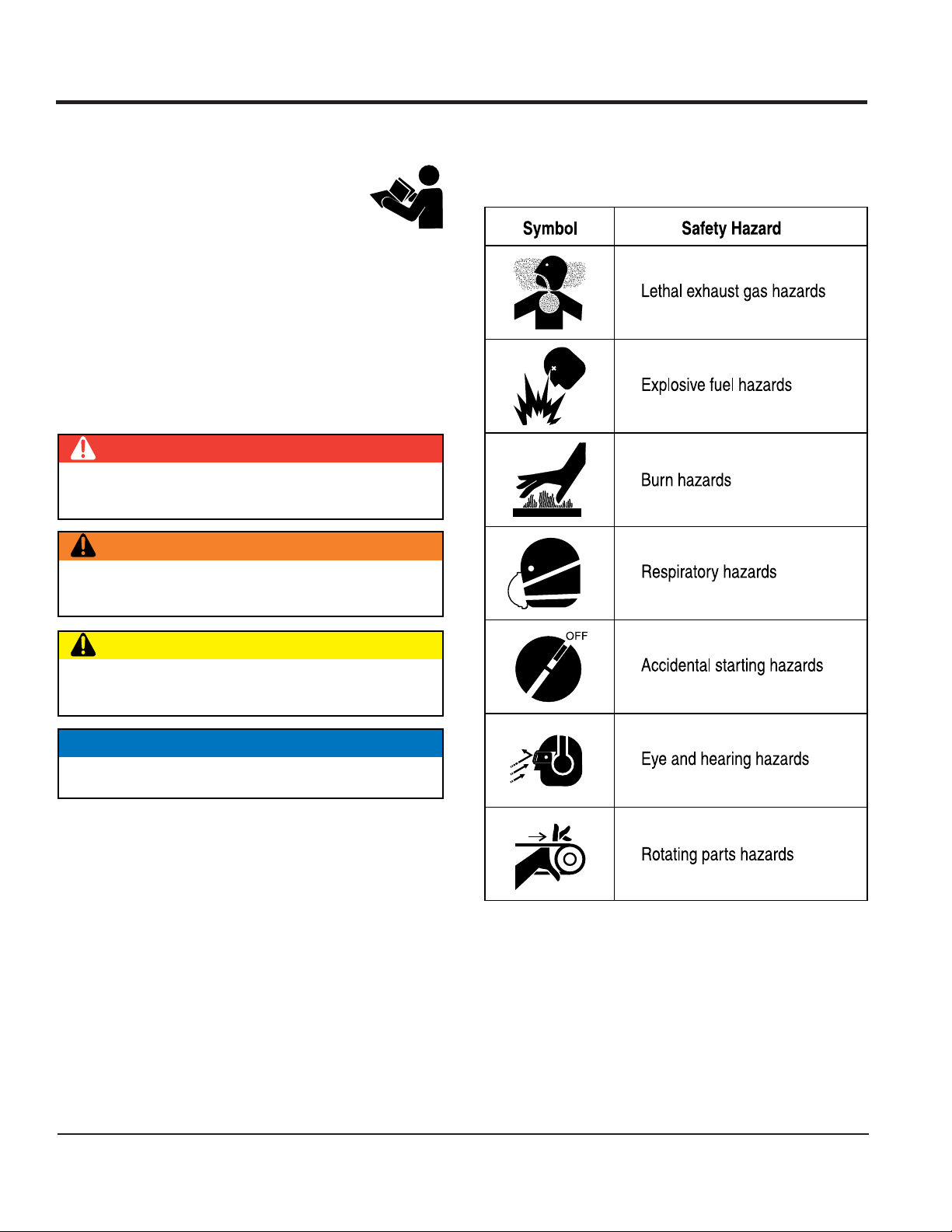
SAFETY MESSAGES
The four safety messages shown below will inform you
about potential hazards that could injure you or others. The
safety messages specifically address the level of exposure
to the operator and are preceded by one of four words:
DANGER, WARNING, CAUTION or NOTICE.
SAFETY SYMBOLS
DANGER
Indicates a hazardous situation which, if not avoided,
WILL result in DEATH or SERIOUS INJURY.
WARNING
Potential hazards associated with the operation of this
equipment will be referenced with hazard symbols which
may appear throughout this manual in conjunction with
safety messages.
Indicates a hazardous situation which, if not avoided,
COULD result in DEATH or SERIOUS INJURY.
CAUTION
Indicates a hazardous situation which, if not avoided,
COULD result in MINOR or MODERATE INJURY.
NOTICE
Addresses practices not related to personal injury.
PAGE 6 — MVC98D2 PLATE COMPACTOR — OPERATION AND PARTS MANUAL — REV. #1 (1/12/11)
Page 7
SAFETY INFORMATION
GENERAL SAFETY
CAUTION
NEVER operate this equipment without proper protective
clothing, shatterproof glasses, respiratory protection,
hearing protection, steel-toed boots and other protective
devices required by the job or city and state regulations.
NEVER operate this equipment when not
feeling well due to fatigue, illness or when
under medication.
NEVER operate this equipment under the influence of
drugs or alcohol.
ALWAYS check the equipment for loosened threads or
bolts before starting.
DO NOT use the equipment for any purpose other than
its intended purposes or applications.
NOTICE
This equipment should only be operated by trained and
qualified personnel 18 years of age and older.
Whenever necessary, replace nameplate, operation and
safety decals when they become difficult read.
Manufacturer does not assume responsibility for any
accident due to equipment modifications. Unauthorized
equipment modification will void all warranties.
NEVER use accessories or attachments that are not
recommended by Multiquip for this equipment. Damage
to the equipment and/or injury to user may result.
ALWAYS know the location of the nearest
fire extinguisher.
ALWAYS know the location of the nearest
first aid kit.
ALWAYS know the location of the nearest phone or keep
a phone on the job site. Also, know the phone numbers
of the nearest ambulance, doctor and fire department.
This information will be invaluable in the case of an
emergency.
ALWAYS clear the work area of any debris, tools, etc.
that would constitute a hazard while the equipment is
in operation.
MVC98D2 PLATE COMPACTOR — OPERATION AND PARTS MANUAL — REV. #1 (1/12/11) — PAGE 7
Page 8
r
SAFETY INFORMATION
COMPACTOR SAFETY
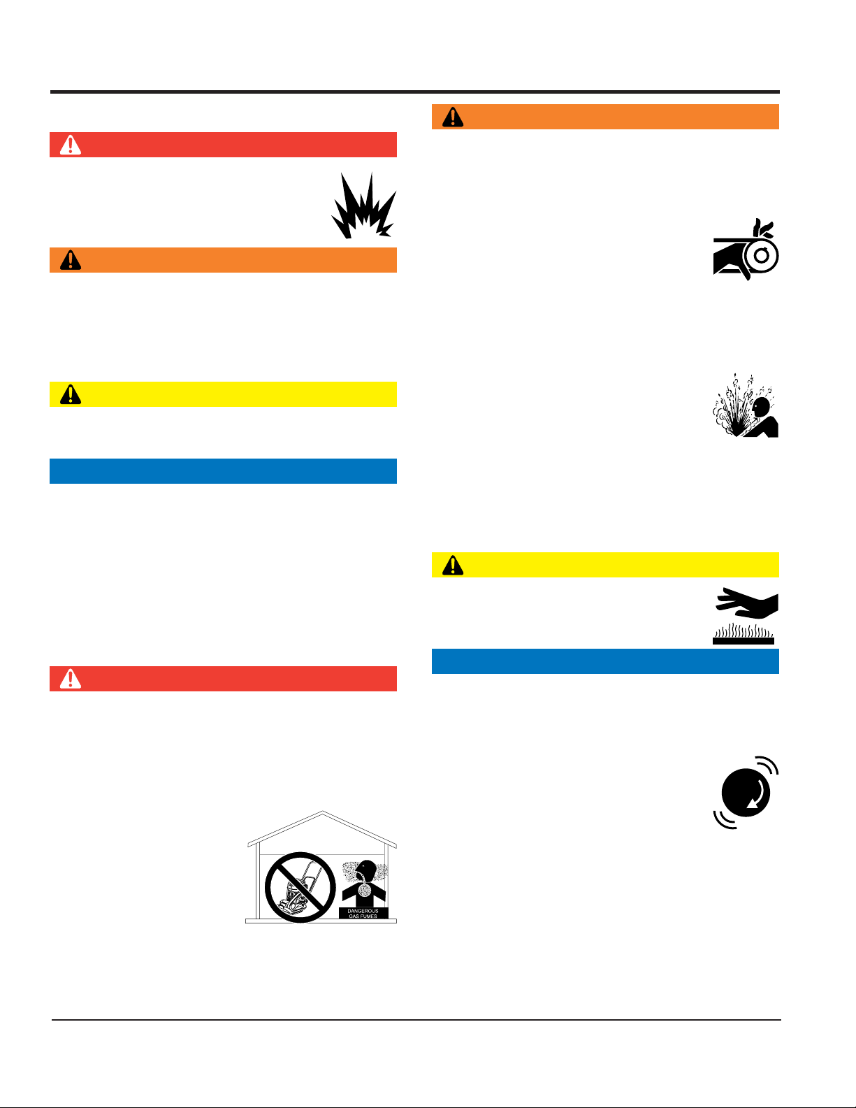
DANGER
NEVER operate the equipment in an explosive
atmosphere or near combustible materials. An
explosion or fire could result causing severe
bodily harm or even death.
WARNING
NEVER disconnect any emergency or safety devices.
These devices are intended for operator safety.
Disconnection of these devices can cause severe injury,
bodily harm or even death. Disconnection of any of these
devices will void all warranties.
CAUTION
NEVER lubricate components or attempt service on a
running machine.
NOTICE
ALWAYS keep the machine in proper running condition.
Fix damage to machine and replace any broken parts
immediately.
ALWAYS store equipment properly when it is not being
used. Equipment should be stored in a clean, dry location
out of the reach of children and unauthorized personnel.
ENGINE SAFETY
DANGER
The engine fuel exhaust gases contain poisonous carbon
monoxide. This gas is colorless and odorless, and can
cause death if inhaled.
The engine of this equipment requires an adequate
free flow of cooling air. NEVER operate this equipment
in any enclosed or narrow
area where free flow of the
air is restricted. If the air
flow is restricted it will cause
injury to people and property
and serious damage to the
equipment or engine.
WARNING
DO NOT place hands or fingers inside engine
compartment when engine is running.
NEVER operate the engine with heat shields or
guards removed.
Keep fingers, hands hair and clothing away
from all moving parts to prevent injury.
DO NOT remove the radiator cap while the
engine is hot. High pressure boiling water will gush out
of the radiator and severely scald any persons in the
general area of the compactor.
DO NOT remove the coolant drain plug
while the engine is hot. Hot coolant will
gush out of the coolant tank and severely
scald any persons in the general area of
the compactor.
DO NOT remove the engine oil drain plug while the
engine is hot. Hot oil will gush out of the oil tank and
severely scald any persons in the general area of the
compactor.
CAUTION
NEVER touch the hot exhaust manifold,
muffler or cylinder. Allow these parts to cool
before servicing equipment.
NOTICE
NEVER run engine without an air filter or with a dirty air
filter. Severe engine damage may occur. Service air filte
frequently to prevent engine malfunction.
NEVER tamper with the factory settings
of the engine or engine governor. Damage
to the engine or equipment can result
if operating in speed ranges above the
maximum allowable.
NEVER tip the engine to extreme angles during lifting as
it may cause oil to gravitate into the cylinder head, making
the engine start difficult.
PAGE 8 — MVC98D2 PLATE COMPACTOR — OPERATION AND PARTS MANUAL — REV. #1 (1/12/11)
Page 9
SAFETY INFORMATION
FUEL SAFETY
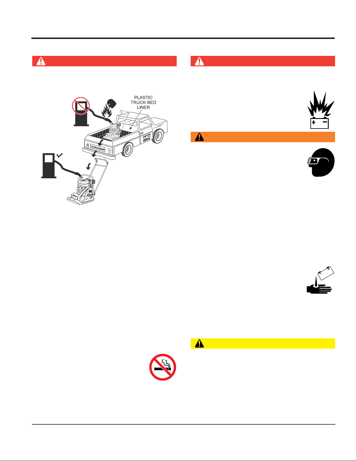
DANGER
DO NOT add fuel to equipment if it is placed inside truck
bed with plastic liner. Possibility exists of explosion or
fire due to static electricity.
FUEL
FUEL
DO NOT start the engine near spilled fuel or combustible
fluids. Diesel fuel is extremely flammable and its vapors
can cause an explosion if ignited.
ALWAYS refuel in a well-ventilated area, away from
sparks and open flames.
ALWAYS use extreme caution when working with
flammable liquids.
DO NOT fill the fuel tank while the engine is running
or hot.
DO NOT overfill tank, since spilled fuel could ignite if it
comes into contact with hot engine parts or sparks from
the ignition system.
Store fuel in appropriate containers, in well-ventilated
areas and away from sparks and flames.
BATTERY SAFETY (ELECTRIC START ONLY)
DANGER
DO NOT drop the battery. There is a possibility that the
battery will explode.
DO NOT expose the battery to open flames,
sparks, cigarettes, etc. The battery contains
combustible gases and liquids. If these
gases and liquids come into contact with a
flame or spark, an explosion could occur.
WARNING
ALWAYS wear safety glasses when
handling the battery to avoid eye irritation.
The battery contains acids that can cause
injury to the eyes and skin.
Use well-insulated gloves when picking up
the battery.
ALWAYS keep the battery charged. If the battery is not
charged, combustible gas will build up.
DO NOT charge battery if frozen. Battery can explode.
When frozen, warm the battery to at least 61°F (16°C).
ALWAYS recharge the battery in a well-ventilated
environment to avoid the risk of a dangerous concentration
of combustible gases.
If the battery liquid (dilute sulfuric acid)
comes into contact with clothing or skin,
rinse skin or clothing immediately with
plenty of water.
If the battery liquid (dilute sulfuric acid) comes into
contact with eyes, rinse eyes immediately with plenty
of water and contact the nearest doctor or hospital to
seek medical attention.
NEVER use fuel as a cleaning agent.
DO NOT smoke around or near the
equipment. Fire or explosion could result
from fuel vapors or if fuel is spilled on a
hot engine.
CAUTION
ALWAYS disconnect the NEGATIVE battery terminal
before performing service on the equipment.
ALWAYS keep battery cables in good working condition.
Repair or replace all worn cables.
MVC98D2 PLATE COMPACTOR — OPERATION AND PARTS MANUAL — REV. #1 (1/12/11) — PAGE 9
Page 10

TRANSPORTING SAFETY
CAUTION
NEVER allow any person or animal to stand underneath
the equipment while lifting.
NOTICE
Before lifting, make sure that the equipment parts (hook
and vibration insulator) are not damaged and screws are
not loose or missing.
Always make sure crane or lifitng device has been
properly secured to the lifting bail (hook) of the
equipment.
ALWAYS shutdown engine before transporting.
NEVER lift the equipment while the engine is running.
Tighten fuel tank cap securely and close fuel cock to
prevent fuel from spilling.
SAFETY INFORMATION
Use adequate lifting cable (wire or rope) of sufficient
strength.
Use one point suspension hook and lift straight
upwards.
DO NOT lift machine to unnecessary heights.
ALWAYS tie down equipment during transport by
securing the equipment with rope.
ENVIRONMENTAL SAFETY
NOTICE
Dispose of hazardous waste properly.
Examples of potentially hazardous waste
are used motor oil, fuel and fuel filters.
DO NOT use food or plastic containers to dispose of
hazardous waste.
DO NOT pour waste, oil or fuel directly onto the ground,
down a drain or into any water source.
PAGE 10 — MVC98D2 PLATE COMPACTOR — OPERATION AND PARTS MANUAL — REV. #1 (1/12/11)
Page 11
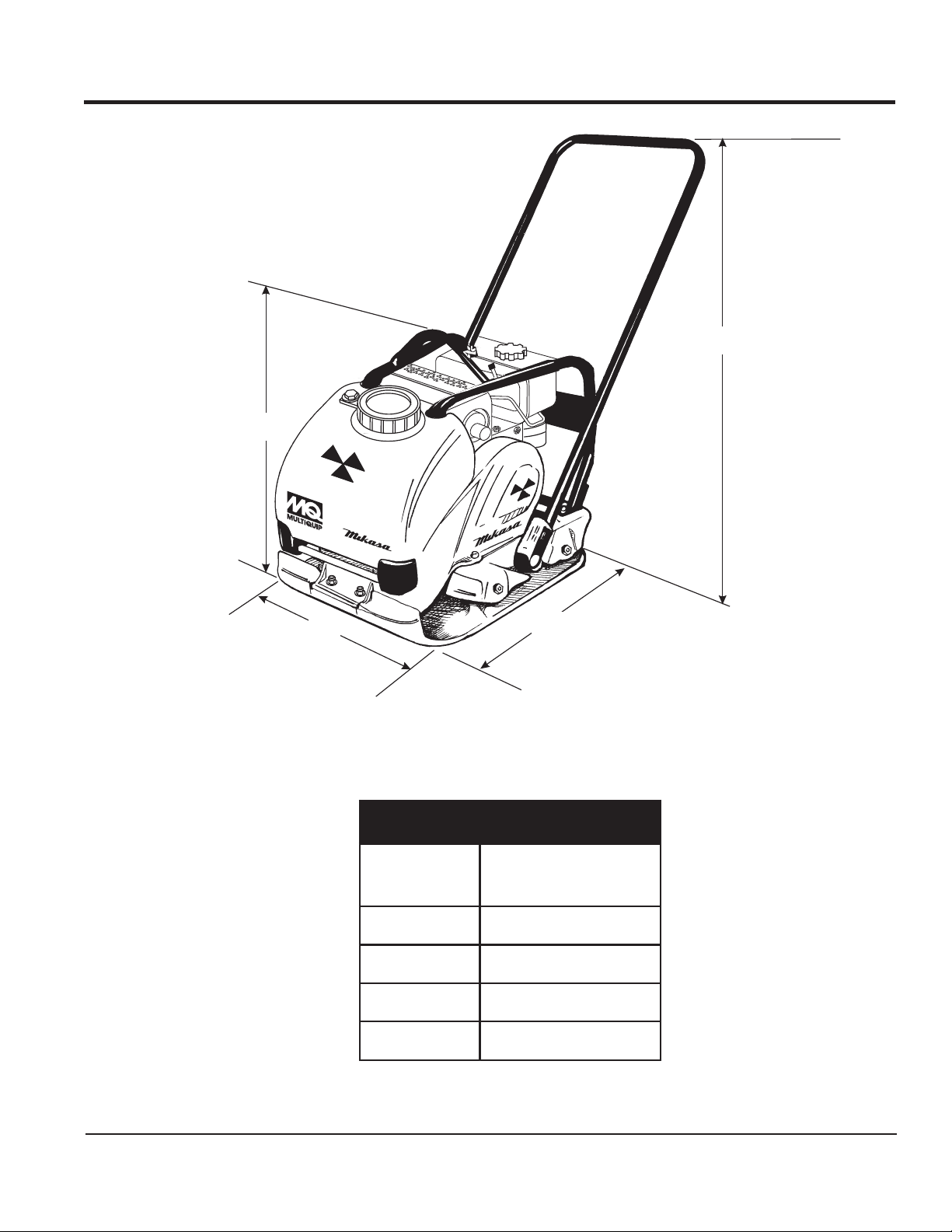
B
DIMENSIONS
C
A
Figure 1. MVC98D2 Reversible Plate Compactor Dimensions
D
SNOISNEMID.1ELBAT
ECNEREFER
RETTEL
A
B
C
D
SNOISNEMID
)MM(.NI
).mm205(.ni57.91
).mm066(.ni62
).mm610,1(.ni04
).mm875(.ni57.22
MVC98D2 PLATE COMPACTOR — OPERATION AND PARTS MANUAL — REV. #1 (1/12/11) — PAGE 11
Page 12
sledoM2D89-CVM
ecroFlagufirtneC)gk025,1(.sbl053,3
SPECIFICATIONS
)rotcapmoC(snoitacificepS.2ELBAT
snoitarbiVforebmuNnim/sn
oitarbiv000,6
deepSgnilevarT)nim/sretem22(nim/.tf27
)WxL(eziSetalP
thgieWgnitarepO)
.ni0.22x6.91
)mm955x894(
gk99(.sbl812
yticapaCknaTretaW)sretil0.31(.tq7.31
noitcapmoCfOaerA.xaM.rh/.tf.qs2907
)enignE(snoitacificepS.3elbaT
ledoM
epyT
RAMNAY
4WAA4R3F6V84L
lacitreV,ekorts4delooc-riA
leseiD,rednilyCelgniS
enignE
.ni
ekortSXeroB
enignE
leuFleuFleseiD
isnemiD
thgieWteNyrD
)HxWxL(no
tnemecalpsiD)ni-uc4.31(cc912
tuptuOxaM.M.P.R0063/.P.H2.4
yticapaCknaTleuF
yticapaCliOebuL)sretil08.(.stq48.0
dohteMgnitratStratSlioceR
8.1x.ni7.2
)mm75xmm07(
36.0.xorppA
snollag.S.U
)sretil4.2(
.ni5.61x1.51x1.31
mm8.714x5.483x5.233(
).gK5.62(sbl4.85
PAGE 12 — MVC98D2 PLATE COMPACTOR — OPERATION AND PARTS MANUAL — REV. #1 (1/12/11)
Page 13

GENERAL INFORMATION
Plate Compactor
The Mikasa MVC98D2 is a walk-behind plate compactor
designed for the compaction of sand, clay and asphalt. This plate
compactor is a powerful compacting tool capable of applying a
tremendous force in consecutive high frequency vibrations to a
soil surface. Its applications include soil compacting for road,
embankments and reservoirs as well as backfilling for gas
pipelines, water pipelines and cable installation work.
Compactor Components
This plate compactor is comprised of an anti-vibration handle,
vibrating case (eccentric), water tank, guard hook, rubber shock
absorbers and a Yanmar diesel engine.
Vibratory Plates
The vibratory plates of the MVC98D2 produce low amplitude
high frequency vibrations, designed to compact granular soils
and asphalt.
The resulting vibrations cause forward motion. The engine and
handle are vibration isolated from the vibrating plate. The heavier
the plate, the more compaction force it generates.
Power Transfer
Frequency/Speed
The compactor's vibrating plate maximum frequency is 6,000
vpm (vibrations per minute). The forward and reverse travel speed
of the compactor is approximately 72 ft./minute (22 meters/
minute).
Water Sprinkler System
The water sprinkler system will provide about 20 minutes of
sprinkling with the water cock in the full open position and the
compactor operating at full speed. It is suggested to mix a small
amount of detergent or diesel fuel with water. This will allow the
water to the flow much easier.
Controls
Before starting the MVC98D2 Plate Compactor, identify and
understand the function of the controls and components as
indicated in Figure 2.
The Mikasa MVC98D2 Plate Compactor is equipped with an aircooled, vertical single-cylinder, 4-stroke Yanmar L48V6 diesel
engine. A centrifugal clutch is attached to the output shaft of the
engine and will engage when the engine speed reaches
approximately 2,300 ~ 2,600 rpm’s.
Engine shaft speed is transfered via engine pulley and V-belt to
vibrator pulley. The vibrator pulley rotates an eccentric rotor shaft
that is contained within the vibrator case.
The generated vibration created from the eccentric rotor is
transmitted to the compacting plate. This vibration causes the
compactor to move in a forward direction.
MVC98D2 PLATE COMPACTOR — OPERATION AND PARTS MANUAL — REV. #1 (1/12/11) — PAGE 13
Page 14
9
10
1
COMPONENTS
4
2
3
8
7
6
Figure 2. MVC98D2 Components
Figure 2 illustrates the location of the major components for the
MVC98D2 Plate Compactor. The function of each component is
described below:
1. Water Tank Cap – Remove this cap to add water to the
water tank.
2. Lifting Hook – When lifting of the compactor is required
either by forklift, crane etc., tie rope or chain around this
lifting point.
3. Diesel Engine – This plate compactor uses a YANMAR
L48V6 engine. Refer to the YANMAR owners manual for
engine information and related topics.
4. Handle Bar – When operating the compactor use this
handle bar to manuever the compactor.
5. Belt Cover – Remove this cover to gain acess to the V-belt.
NEVER run the compactor without the V-belt cover. If the Vbelt cover is not installed, the possibility exist that your hand
may get caught between the V-belt and clutch, thus causing
serious injury and bodily harm.
6. Vibrating Plate – A flat, open plate made of durable cast
iron construction used in the compacting of soil.
7. Vibration Case – Encloses the eccentric, gears and
counter weights.
8. Water Tube (Sprinkler) – Supplies water to the soil via a
splash plate.
9. Water Shut-Off Valve – Turn this valve downward to let
water flow from the water tank to the water tube.
5
10. Water Tank – Holds 13.7 quarts of water, removable no
tools required.
PAGE 14 — MVC98D2 PLATE COMPACTOR — OPERATION AND PARTS MANUAL — REV. #1 (1/12/11)
Page 15
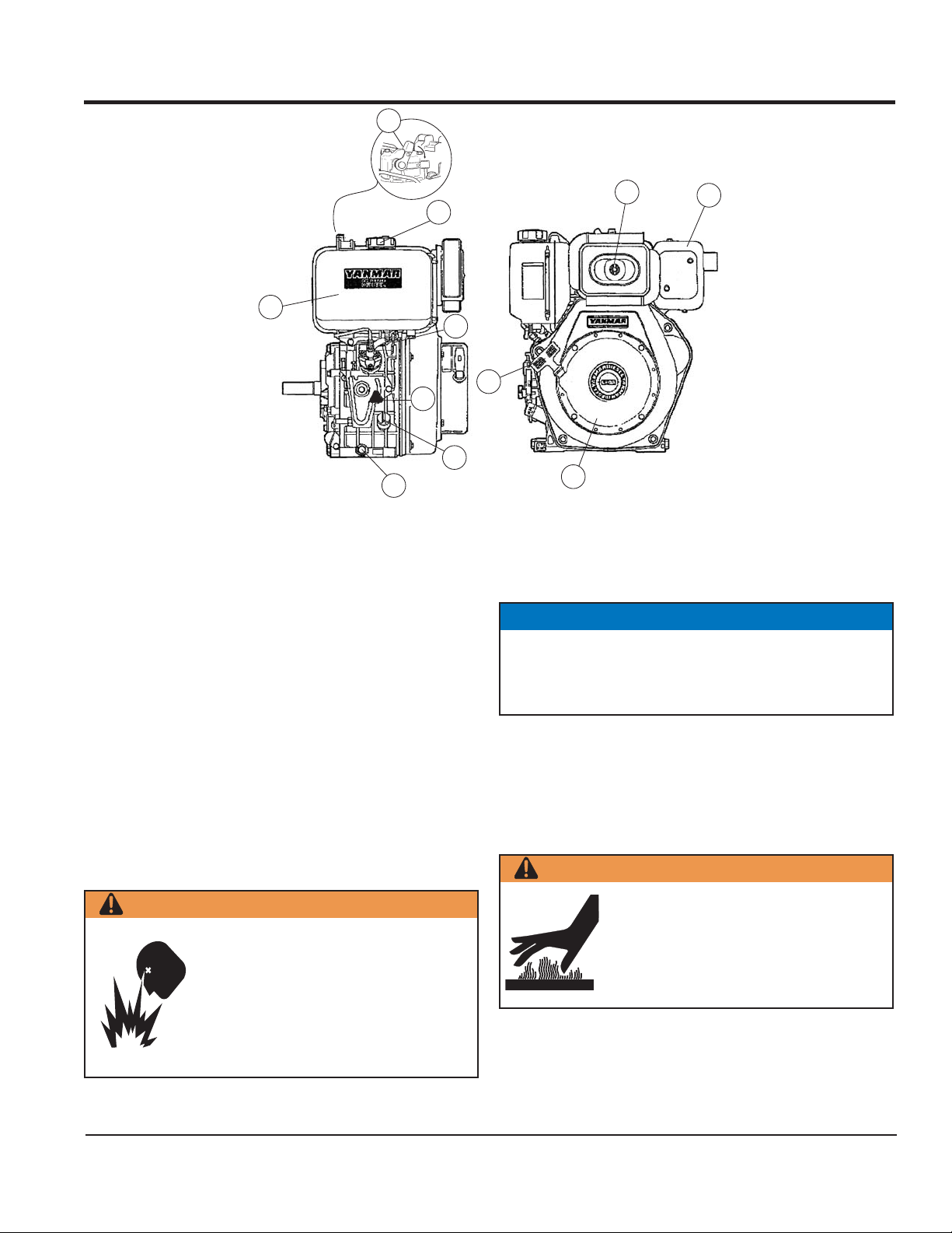
BASIC ENGINE
9
1
2
10
5
11
7
8
Figure 3. Engine Controls and Components
The engine shown above is a
YANMAR L48V6
engine (Figure 3).
The engine must be checked for proper lubrication and filled
with fuel prior to operation. Refer to the manufacturer’s engine
manual for instructions and details of operation and servicing.
Each component is described below:
1. Fuel Filler Cap – Remove this cap to add unleaded
gasoline to the fuel tank. Make sure cap is tightened
securely. DO NOT over fill.
7. Oil Filler Cap / Dipstick – Remove this cap to add oil to the
engine crankcase. Read dipstick to determine if oil level is
low. DO NOT over fill.
NOTICE
Operating the engine without an air filter, with a damaged air
filter, or a filter in need of replacement will allow dirt to enter
the engine, causing rapid engine wear.
2. Fuel Tank – Capacity is 2.5 quarts (2.4 liters) of diesel
fuel.
3. Air Cleaner – Prevents dirt and other debris from entering
the fuel system. Remove wing-nut on top of air filter
cannister to gain access to filter element.
4. Muffler – Used to reduce noise and emissions.
8. Oil Drain Plug – Unscrew plug to drain oil from engine
crankcase. Dispose of oil in a safe manner.
9. Decompression Lever– Press down before starting
engine. To prevent damage to engine, DO NOT use for any
other purpose.
3
6
4
5. Recoil Starting Handle (pull rope) – Type of engine
starting method.
WARNING
WARNING
Engine components can generate extreme
heat. To prevent burns, DO NOT touch these
Add fuel to the tank only when the engine is
stopped and has cooled down. In the event
of a fuel spill, DO NOT attempt to start the
areas while the engine is running or
immediately after operating. NEVER operate
the engine with the muffler removed.
engine until the fuel residue has been
completely wiped up and the area
surrounding the engine is dry.
10. Fuel Cock– Controls the flow of diesel fuel to the carburetor.
Must be in the ON position when starting and running the
engine.
6. Recoil Starter– Manual-starting method. Pull the starter
11. Speed Control Lever– Regulates engine speed.
grip until resistance is felt, then pull briskly and smoothly.
MVC98D2 PLATE COMPACTOR — OPERATION AND PARTS MANUAL — REV. #1 (1/12/11) — PAGE 15
Page 16
SETUP
Compactor Instructions
The purpose of this section is to assist the user in the setting
up of a NEW compactor
. If your compactor is already
assembled (vibration handle), then this section can be
Steering Handle Assembly
The steering handle is not attached to the compactor’s lower
base at the time of shipment. To attach the steeering handle
to the lower base assembly perform the following:
skipped.
Before packaging and shipping this MQ Mikasa Walk-Behind
Plate compactor was run and tested at the factory. If there
are problems, please let us know.
NOTICE
The new plate compactor cannot be put into service until
the setup installation instructions are completed. These
setup instructions only need to be performed at the time
1. Remove the bolts and washers (handle mounting hardware) from both sides of the plate compactor (Figure 4).
2. Position the anti-vibration handle over the compactor.
3. Align the holes at the bottom of the handle to the holes
on the compactor (lower base) where the bolts and washers where removed. Install and tighten the bolts and
washers.
of unpacking a NEW compactor.
ANTI-VIBRATION
HANDLE
BASE PLATE
HANDLE MOUNTING
HARDWARE
Figure 4. Installing the Steering Handle
PAGE 16 — MVC98D2 PLATE COMPACTOR — OPERATION AND PARTS MANUAL — REV. #1 (1/12/11)
Page 17
INSPECTION
CAUTION
NEVER operate the unit in a confined
area or enclosed area structure that does
not provide ample
free flow of air
CAUTION
ALWAYS wear approved eye and hearing
protection before operating the unit.
Before Starting:
1. Read safety instructions at the
beginning of manual.
2. Remove dirt and dust, particularly
in the engine cooling air inlet,
carburetor and air cleaner.
3. Check the air filter for dirt and dust.
If air filter is dirty, replace air filter
with a new one as required.
3. Insert and remove the dipstick without screwing it into the filler
neck. Check the oil level shown on the dipstick.
4. If the oil level is low (Figure 6), fill to the edge of the oil filler
.
hole with the recommended oil type (Table 4). Maximum oil
capacity is 0.84 quarts (0.80 liters).
Figure 6. Engine Oil Dipstick (Oil Level)
epyTliO.4elbaT
nosaeS erutarepmeT epyTliO
remmuS rehgiHroC°52 03-W01EAS
llaF/gnirpS C°01~C°52 02/03-W01EAS
4. Check carburetor for external dirt and dust. Clean with dry
compressed air.
5. Check fastening nuts and bolts for tightness.
Engine Oil Check:
1. To check the engine oil level, place the compactor on secure
level ground with the engine stopped.
2. Remove the filler dipstick from the engine oil filler hole
(Figure 5) and wipe clean.
DANGER
Fuel Check:
1. Remove the fuel cap located on top of fuel tank.
2. Visually inspect to see if the fuel level is low. If fuel is low,
replenish with clean diesel fuel.
3. When refueling, be sure to use a strainer for filtration. DO NOT
top-off fuel. Wipe up any spilled fuel
retniW rewoLroC°0 01-W01EAS
EXPLOSIVE FUEL!
Explosive
Motor fuels are highly flammable and can
Fuel
be dangerous if mishandled. DO NOT
smoke while refueling. DO NOT attempt to
refuel if the engine is
hot or running
immediately!
.
Figure 5. Engine Oil Dipstick (Removal)
MVC98D2 PLATE COMPACTOR — OPERATION AND PARTS MANUAL — REV. #1 (1/12/11) — PAGE 17
Page 18

INSPECTION
V-Belt Check
2. The V-belt tension is proper if the V-belt bends 10 to 15 mm
CAUTION
NEVER attempt to check the V-belt with the engine running.
Severe injury can occur of your hand (Figure 7) gets caught
between the V-belt and the clutch. Always use safety gloves.
CLUTCH
PULLEY
3. A loose V-belt will decrease the power transmission output,
VIBRATOR
PULLEY
4. If the V-belt becomes worn or loose, replace it. See
Figure 7. V-Belt Hazard
1. To check the V-belt tension, remove the three bolts that
secure the belt cover to the frame as shown in Figure 8.
Vibrator Oil Check
(Figure 9) when depressed with finger at midway between
the clutch and vibration pulley shafts.
Figure 9. V-Belt Tension
causing reduced compaction and premature wear of the
belt.
maintenance section.
VIBRATOR
V-BELT
REMOVE
V-BELT COVER
REMOVE
Mikasa
1. Place the MVC98D2 plate compactor horizontally on a flat
surface. Make sure the compactor is level when checking the
oil in the vibrator assembly.
2. Check vibrator oil level by removing the plug (vibrator oil gauge)
as shown in Figure 10. The oil level should be up to the oil plug.
The vibrator holds 140 cc (approximately 4 oz.). IMPORTANT,
if oil is required, replace using only SAE10W-30 motor oil.
Figure 10. Vibrator Oil Plug
Figure 8. V-Belt Cover Removal
PAGE 18 — MVC98D2 PLATE COMPACTOR — OPERATION AND PARTS MANUAL — REV. #1 (1/12/11)
Page 19
OPERATION
This section is intended to assist the operator with the
start-up
of the compactor. It is extremely important that this
section be read carefully before attempting to use the compactor
in the field.
initial
4. Grasp the starter grip (Figure 14) and slowly pull it out. The
resistance becomes the hardest at a certain position, corresponding to the compression point. Pull the starter grip briskly
and smoothly for starting.
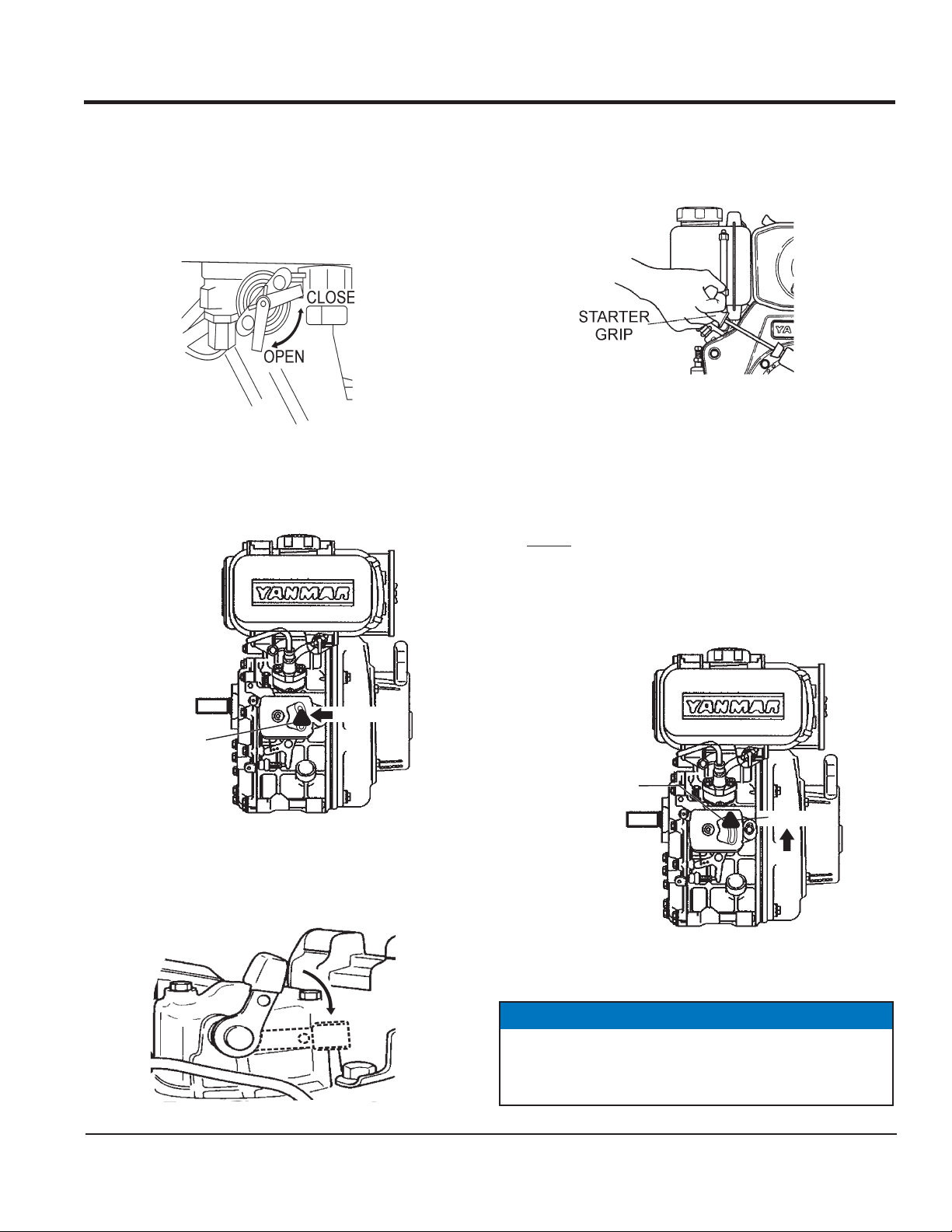
Starting the Engine
1. Open the fuel cock
(Figure 11).
5. If the engine does not start, repeat steps 1 thru 4.
Figure 11. Fuel Cock
2. Move the engine speed control lever (Figure 12) to the
Operation
IDLE position.
1. Once the engine has started, move the engine speed lever
quickly
2. With the engine speed control lever placed in the FAST
position, the engine speed should be between 2,300 ~2,600
RPM’s, therefore engaging the centrifugal clutch.
to the
Figure 14. Starter Grip
FAST
(Figure 15) position.
ENGINE SPEED
CONTROL
LEVER
IDLE
ENGINE SPEED
CONTROL
LEVER
FAST
Figure 12. Engine Speed Control Lever (Idle Position)
3. Push down the decompression lever (Figure 13) and release.
Figure 15. Speed Control Lever (Fast Position)
NOTICE
ALWAYS
move the throttle lever quickly without
hesitation, because increasing the engine speed slowly
causes the clutch to slip.
Figure 13. Decompression Lever
MVC98D2 PLATE COMPACTOR — OPERATION AND PARTS MANUAL — REV. #1 (1/12/11) — PAGE 19
Page 20
OPERATION/PREPARATION FOR LONG-TERM STORAGE
CAUTION
Normal Shut-Down Procedure:
1. Place the speed control lever in the IDLE position. Allow the
Make sure to follow all safety rules referenced in the safety
engine to cool down for 2 to 3 minutes.
information section of this manual before operating compactor. Keep work area clear of debris and other objects that could
cause damage to the compactor or bodily injury.
2. Next, place the speed control lever in the STOP position
(Figure 16) to stop the engine.
3. Close the fuel cock (Figure 11).
3. Firmly gasp the compactor's handle bar with both hands , the
compactor will begin moving forward.
4. Slowly walk behind the compactor and be on the lookout for
any large objects or foreign matter that might cause damage
to the compactor or bodily injury.
5. Compactor traveling speed may drop on soils which contain
clay, however there may be cases where traveling speed
drops because the compaction plate does not leave the
ground surface easily due to the composition of the soil. To
rectify this problem do the following:
■
Check the bottom plate to see if clay or equivalent material
has been lodged in the plate mechanism. If so, wash with
water and remove.
■
Remember the compactor does not work as efficiently on
clay or soils that have a high moisture content level.
■
If the soil has a high moisture level, dry soil to appropriate
moisture content level or carry out compaction twice.
Figure 16. Speed Control Lever (Stop Position)
Emergency Shutdown Procedure:
1. Move the speed control lever quickly to the STOP
(Figure 16).
2. Close the fuel cock.
NOTICE
Whenever the compactor's vibration becomes weak or lost
during normal operation, regardless of operation hours, check
the V-belt and clutch immediately.
Compactor Storage
For storage of the compactor for over 30 days, the following
is required:
SPEED
CONTROL
LEVER
STOP
position
■
Drain the fuel tank completely, or add STA-BIL to the fuel.
■
Run the engine until the fuel in the injection system is
completely consumed.
■
Completely drain the oil from the crankcase and refill with
fresh oil.
■
Pour 2 or 3 cc of SAE 30 oil into the cylinder and crank slowly
to distribute the oil.
■
Pull out the starter rope slowly and stop at the compression
point.
■
Clean all external parts of the compactor with a cloth.
■
Cover the compactor and store in a clean, dry place.
PAGE 20 — MVC98D2 PLATE COMPACTOR — OPERATION AND PARTS MANUAL — REV. #1 (1/12/11)
Page 21

MAINTENANCE
CAUTION
Inspection and other services should
on hard and level ground with the engine shutdown.
always
be carried out
METINOITAREPOFOSRUOH
Inspection and Maintenance Service Tables.
To make sure your plate compactor is always in good working
sdaerhT
condition before using, carry out the maintenance inspection in
accordance with Tables 5 through 7.
2D89-CVM.5ELBATENIHCAM
NOITCEPSNI
METI
gnissiMroesooL
swercS
straPdegamaD
tleB-V
tnemecalpeR/kcehC
FOSRUOH
NOITAREPO
yreve(sruoh8yrevE
)yad
yreve(sruoh8yrevE
)yad
sruoh002yrevE
Daily Service
Check for leakage of fuel or oil.
Check for loose screws including tightness. See Table 7
below (tightening torque ), for retightening:
kaeLleuFroliO)yadyreve(sruoh8yrevE
gninetsaFfossenthgiT
dnakcehCliOenignE
tnemhsinelpeR
tnemecalpeRliOenignE
gninaelCretliFriAsruoh001yrevE
2D89-CVM.6ELBATKCEHCENIGNE
)yadyreve(sruoh8yrevE
)yadyreve(sruoh8yrevE
mumixamdeificepsothsinelpeR(
)level
ot05yrevenehtsruoh52tsrifretfA
sruoh001
.ecnanetniamenignenosliatedroflaunamenigneetarapeseeS
kcehChctulCsruoh002yrevE
kcehCliOrotarbiVsruoh001yrevE
liOrotarbiV
tnemecalpeR
kcehChctulCsruoh002yrevE
NOTICE
sruoh003yrevE
T4 07 051 003 005 057 001,1 004,1 000,2
T8-6 001 052 005 008 003,1 000,2 007,2 008,3
T11 051 004 008 002,1 000,2 009,2 002,4 006,5
* 001
These inspection intervals are for operation under normal
conditions. Adjust your inspection intervals based on the number
hours plate compactor is in use, and particular working
conditions. Fuel piping and connections should be replaced
every 2 years.
Remove soil and clean the bottom of compaction plate.
Check vibrating case for any oil leakage.
Check engine oil.
.7ELBAT
mm6 mm8 mm01 mm21 mm41 mm61 mm81 mm02
lairetaM
~003
~056
053
007
)munimulafositrap-retnuocesacnI(*
)dednahthgirllaeraenihcamsihthtiwesunisdaerhT(
retemaiD)mc/gk.ni(EUQROTGNINETHGIT
.wercsdna,tlobhcaenodekramsilairetamfoytilauqdnalairetaM
MVC98D2 PLATE COMPACTOR — OPERATION AND PARTS MANUAL — REV. #1 (1/12/11) — PAGE 21
Page 22

MAINTENANCE
Engine Oil Replacement
1. Replace engine oil, first in 25 hours of operation and every
50 to 100 hours afterwards.
2. Drain the engine oil when the oil is
Figure 17.
Figure 17. Engine Oil (Draining)
3. Remove the oil drain bolt and sealing washer and allow the
oil to drain into a suitable container.
4. Replace engine oil in the oil tank with recommended type
oil as listed in Table 4. Engine oil capacity is 1.16 quarts (1.1
liter). DO NOT overfill.
5. Install drain bolt with sealing washer and tighten securely.
warm
as shown in
Checking and the V-Belt
After 200 hours of operation, remove the belt cover to check the Vbelt tension (Figure 19).
1. Remove the belt cover.
2. Tension is proper if the belt bends about 10 mm when
depressed strongly with finger between shafts. Loose or worn
V-belts reduces power transmission efficiency, causing weak
compaction and reduces the life of the belt itself.
CAUTION
Figure 19. Checking V-belt Tension
Air Filter Cleaning
1. Remove the air cleaner cover and foam filter element as
shown in Figure 18.
2. Tap the paper filter element (Figure 18) several times on a hard
surface to remove dir t, or blow compressed air [not exceeding
30 psi (207 kPa, 2.1 kgf/cm
air cleaner case side.
CAUTION
NEVER brush off dirt. Brushing will force dirt into the fibers
and cause poor performance in your air filter. Replace the
paper filter element if it is excessively dirty.
3. Clean foam element in warm, soapy water or nonflammable
solvent. Rinse and dry thoroughly. Dip the element in clean
engine oil and completely squeeze out the excess oil from the
element before installing.
2
)] through the filter element from the
Replacing the V-belt
1. Remove the V-belt cover (Figure 20).
2. Using cutters, simply cut the worn or defective V-belt and
3. Place one end of the new V-belt onto the upper pulley (clutch
4. Place a 19 mm offset wrench or the like onto the lower vibrator
5. Place the other end of the V-belt onto lower vibrator pulley.
discard.
side).
pulley fastening bolt.
Rotate offset wrench clockwise so that the V-belt moves onto
the lower vibrator pulley.
NEVER attempt to check the V-belt with
the engine running. Severe injury can
occur if your hand gets caught between
the V-belt and the clutch. Always use
safety gloves.
Figure 18. Engine Air Filter
PAGE 22 — MVC98D2 PLATE COMPACTOR — OPERATION AND PARTS MANUAL — REV. #1 (1/12/11)
Page 23

VIBRATOR
REMOVE
REMOVE
MAINTENANCE
Checking and Replacing the Clutch
Checking the Clutch
1. With belt cover removed, visually check outer drum of the
clutch for seizure and "V" groove for wear or damage.
2. Clean the "V" groove as necessary.
3. Check the clutch lining and shoe for signs of wear. If the shoe
is worn, replace the clutch to prevent deficient power
transmission and slippage.
Replacing the Clutch
1. Place a 19 mm offset wrench or the like onto the lower vibrator
pulley fastening bolt.
Mikasa
V-BELT
2. While pulling back hard on the V-belt near the lower vibrating
pulley, rotate offset wrench clockwise so that the V-belt slips
off the lower vibrator pulley. Set V-belt aside.
3. Remove bolt at engine power output by giving a shock to an
V-BELT COVER
Figure 20. V-Belt Check
Vibrating Case Oil Replacement (300 Hours)
engaged wrench (e.g. tapping with hammer) and rotate the
bolt counterclockwise.
4. Remove clutch with a pulley extractor.
5. To install a new clutch, reverse steps 1-4.
CAUTION
Always clean the area around the vibrator oil plug (oil level
check) hole before removing plug. This will prevent dirt and
debris from entering the system.
1. Place the plate compactor horizontally on a flat surface.
2. Remove oil drain plug (Figure 21) from vibrator and drain oil
from the vibrating case.
3. Using a funnel, fill vibrating case with SAE10W-30 motor
oil.The oil level should be up to the oil plug. The vibrator holds
140 cc (approximately 1 pint).
4. Re-install oil drain plug into vibrator.
Figure 21. Oil Level Check Plug
MVC98D2 PLATE COMPACTOR — OPERATION AND PARTS MANUAL — REV. #1 (1/12/11) — PAGE 23
Page 24

TROUBLESHOOTING
GNITOOHSELBUORTENIGNE.8ELBAT
MOTPMYSMELBORPELBISSOPNOITULOS
?noitisop"POTS"nisirevellortnocdeepS .noitisop"TRATS"otrevellortnocdeepsteS
itcejnignihcaerleufoN .metsysleuferitnekcehC.leufddA
?pmupleufevitcefeD.pmupleufecalpeR
F .knatnaelcdnaretlifleufecalpeR
sitratsrotratstonlliwenignE
deyaled
.revodenruteb
woltA
.tratston
nacenignehguohtla,
lliwenigneserutarepmet
lelttorhT .noitisopNURotrevelelttorhtnoitisopeR
sanoosspotstubserifenignE
.ffodehctiwssiretrats
?deggolcretlifleu
?enilylppusleufytluaF .enilleufriaperroecalpeR
?wolootnoisserpmoC
?wolooterusserpliO .erusserplioenignekcehC
?serutarepmetwol
?kcihtootlioenignE
?dekcolbretlifleuF.retlifleufecalpeR
?dekcolbylppusleuF .metsysleuferitneehtkcehC
?pmupno
rotsujdA.sevlavdnarednilyc,notsipkcehC
.launamriaperenignerepriaper
?yltcerrocgnikrowtonrotcejnileuF
lerutarepmetgnitratswoL
dedeecxetimi
wkcehC
otecnatsiseretauqedanisahsetarapesleuF
.leuf
?noitisopPOTSnireve
.launamriaperenigne
.ytisocsivlioreporp
oenigneehtpu
arcenignellifeR
.tnemnorivneretniwrof
occanirotcejniecalperroriapeR
htiwecnadr
dnasnoitcurtsnignitratsdlochtiwylpmoC
segremeleuf)dibrutton(raelcrehteh
noitcejnimorfhcated(enilleufehtmorf
mraw,detarapesrodibrutsileufehtfI.)pmup
leufetelpmocehtniardr
leseidedargretniwhtiwleufeR.metsysylppus
liofoepyttcerrochtiwesackn
gnirudflestiybspotsenignE
.noitarepolamron
.deeps
tsuahxekcalb,deepswol
.ekoms
uF.retlifleufecalpeR
dnatuptuo,rewopenignewoL
dnatuptuorewopenignewoL
?ytpmeknatleuF.leufddA
?dekcolbretlifle
?ytpmeknatleuF .leufleseid2.oNhtiwlliF
?deggolcretlifleuF.retlifleufecalpeR
?etauqedanisignitnevknatleuF .detnevyletauqedasiknattahterusnE
niniamertonseodrevellortnocdeepS
?noitisopdetceles
?llufootlevellioenignE?levellioenignet
?dekcolbretlifriA .retlifriaecalperronaelC
?secnaraelcevlavtcerrocnI .noitacificepsenignerepsevlavtsujdA
?rotcejnitanoitcnuflaM.launamenigneeeS
.noitcaevitcerrocroflaunamenigneeeS
cerroC
PAGE 24 — MVC98D2 PLATE COMPACTOR — OPERATION AND PARTS MANUAL — REV. #1 (1/12/11)
Page 25

TROUBLESHOOTING
GNITOOHSELBUORTROTCAPMOCETALP.9ELBAT
MOTPMYSESUACELBISSOPNOITULOS
?wolootdeepsenignE .MPRtcerrocotdeepsen
?spilshctulC.hctulcecalperrokcehC
.kaew
.draw
roflevarttonseoD
sinoitarbivdna,wolootdeepslevarT
?spilstleb-V.tleb-VecalperrotsujdA
?rotarbivnilioevissecxE .level
?gnisuohrotarbivninoitcnuflaM
?spilstleb-V.tleb-VecalpeR
?spilshctulC .seohsdnasgnirpshctulckcehC
?dekcolrotarbiV
igneteS
reporpotllifdnaliossecxeniarD
.sthgiew
)sthgiewretnuocdnasraeg
retnuocdnasraeg,cirtneccekcehC
,cirtn
ecce(gnisuohrotarbivkcehC
MVC98D2 PLATE COMPACTOR — OPERATION AND PARTS MANUAL — REV. #1 (1/12/11) — PAGE 25
Page 26

r
”
EXPLANATION OF CODE IN REMARKS COLUMN
The following section explains the different symbols and
remarks used in the Parts section of this manual. Use the
help numbers found on the back page of the manual if there
are any questions.
NOTICE
The contents and part numbers listed in the parts
section are subject to change without notice. Multiquip
does not guarantee the availability of the parts listed.
SAMPLE PARTS LIST
NO. PART NO. PART NAME QTY. REMARKS
1 12345 BOLT ......................1 .....INCLUDES ITEMS W/%
2% WASHER, 1/4 IN. ...........NOT SOLD SEPARATELY
2% 12347 WASHER, 3/8 IN. ...1 .....MQ-45T ONLY
3 12348 HOSE ..................A/R ...MAKE LOCALLY
4 12349 BEARING ..............1 .....S/N 2345B AND ABOVE
NO. Column
Unique Symbols — All items with same unique
symbol
QTY. Column
Numbers Used — Item quantity can be indicated by a
number, a blank entry, or A/R.
A/R (As Required) is generally used for hoses or othe
parts that are sold in bulk and cut to length.
A blank entry generally indicates that the item is not sold
separately. Other entries will be clarified in the “Remarks
Column.
REMARKS Column
Some of the most common notes found in the “Remarks”
Column are listed below. Other additional notes needed
to describe the item can also be shown.
Assembly/Kit — All items on the parts list with the
same unique symbol will be included when this item is
purchased.
Indicated by:
“INCLUDES ITEMS W/(unique symbol)”
(@, #, +, %, or >) in the number column belong to the
same assembly or kit, which is indicated by a note in the
“Remarks” column.
Duplicate Item Numbers — Duplicate numbers indicate
multiple part numbers, which are in effect for the same
general item, such as different size saw blade guards in
use or a part that has been updated on newer versions
of the same machine.
NOTICE
When ordering a part that has more than one item
number listed, check the remarks column for help in
determining the proper part to order.
PART NO. Column
Numbers Used — Part numbers can be indicated by a
number, a blank entry, or TBD.
TBD (To Be Determined) is generally used to show a
part that has not been assigned a formal part number
at the time of publication.
A blank entry generally indicates that the item is not sold
separately or is not sold by Multiquip. Other entries will
be clarified in the “Remarks” Column.
Serial Number Break — Used to list an effective serial
number range where a particular part is used.
Indicated by:
“S/N XXXXX AND BELOW”
“S/N XXXX AND ABOVE”
“S/N XXXX TO S/N XXX”
Specific Model Number Use — Indicates that the part
is used only with the specific model number or model
number variant listed. It can also be used to show a
part is NOT used on a specific model or model number
variant.
Indicated by:
“XXXXX ONLY”
“NOT USED ON XXXX”
“Make/Obtain Locally” — Indicates that the part can
be purchased at any hardware shop or made out of
available items. Examples include battery cables, shims,
and certain washers and nuts.
“Not Sold Separately” — Indicates that an item cannot
be purchased as a separate item and is either part of an
assembly/kit that can be purchased, or is not available
for sale through Multiquip.
PAGE 26 — MVC98D2 PLATE COMPACTOR — OPERATION AND PARTS MANUAL — REV. #1 (1/12/11)
Page 27

MQ MIKASA MVC98D2 PLATE COMPACTOR
W/YANMAR L48V6 DIESEL ENGINE
1 to 3 Units
Qty. P/N Description
3 ......... 070100382 ....... V-BELT A38 (BLUE)
2 ......... 956100050 ....... THROTTLE WIRE
3 ......... 11465012590 ... ELEMENT, A/C W/PRE-FILTER
1 ......... 11429955040 ... CAP, FUEL TANK
1 ......... 11429976630 ... ROPE, RECOIL STARTER
2 ......... 11429935110 ... LUB. OIL FILTER COMPLETE
2 ......... 11425055121 ... FILTER, FUEL STAINER
1 ......... 11429955100 ... FILTER, FUEL OIL
4 ......... 939010230 ....... SOCK ABSORBER
SUGGESTED SPARE PARTS
MVC98D2 PLATE COMPACTOR — OPERATION AND PARTS MANUAL — REV. #1 (1/12/11) — PAGE 27
Page 28

NAMEPLATE AND DECALS ASSY.
2
1
CAUTION
ATTENZIONE
ATENÇAÕ
PRECAUCION
NPA-769 J
NPA-845
* Read operator’s manual carefully before use.
* Libre le manual attentivement avant utillsation.
* Bitte lesen Sie vor inbetriebnahme der Maschine de
Bedienungsanleitung sogfältig durch.
* Prima dell’ uso leggere attentamente il manuale.
* Lee com atenÇão o manual de instruÇões antes de
usar.
* Leer detenidamente el mamual de instrucciones
antes de usar la maquina.
J
3
Serial No.
Model No.
CONTACT
4
NPA-1066
6
8
V BELT RPF-3330
NPA-835
J
5
MQ PARTS DEPT.
5
7
PAGE 28 — MVC98D2 PLATE COMPACTOR — OPERATION AND PARTS MANUAL — REV. #1 (1/12/11)
Page 29

NAMEPLATE AND DECALS ASSY.
NO. PART NO. PART NAME QTY. REMARKS
1 920208450 DECAL, LIFTING POSITION 1 NPA-845
2 920207690 DECAL, CAUTION (MANUAL) 1 NPA-769
3 PLATE, SERIAL NO ..................................... 1 ......... CONTACT MQ PARTS DEPT.
4 920210660 DECAL, DANGER-CAUTION 1 NPA-106
5 920201580 DECAL, MQ LOGO 2 NPA-158
6 920101410 DECAL, MIKASA LOGO (TRIANGLE) 1 NPA-141
7 920105070 DECAL, MIKASA LOGO (NAME) 1 NPA-507
8 920208350 DECAL, V BELT RPF3330 1 NPA-835
MVC98D2 PLATE COMPACTOR — OPERATION AND PARTS MANUAL — REV. #1 (1/12/11) — PAGE 29
Page 30

BODY ASSY.
PAGE 30 — MVC98D2 PLATE COMPACTOR — OPERATION AND PARTS MANUAL — REV. #1 (1/12/11)
Page 31

NO. PART NO. PART NAME QTY. REMARKS
21 416115973 VIBRATING PLATE 1
23 939010230 SHOCK ABSORBER 50D- 45H 4
24 020310080 NUT M10 4
25 030210250 WASHER, LOCK M10 4
31 416115980 BASE 1
32 001221025 BOLT 10 X 25 T 4
33 030210250 WASHER, LOCK M10 4
35 914410024 ENGINE ASSY. L48V6F3R4AAW4 1
36 020310080 NUT M10 4
37 030210250 WASHER, LOCK M10 4
38 031110160 WASHER, FLAT M10 4
39 416456700 ENGINE PLATE /FR (W BOLT) 1
40 416456710 ENGINE PLATE /RE (W BOLT) 1
43 959404350 EARTH WIRE 1
45 458337770 CLUTCH ASSY. A1- 124- 20 1
46 0320050150 KEY 1
47 416452760 COLLAR 20- 25- 15.6 1
48 458451380 CLUTCH /WASHER 1
49 001520825 SOCKET HEAD BOLT 8 X 25 T 1
51 070100382 V- BELT A- 38 (BLUE) 1
52 416216390 BELT COVER (INSIDE) 1
52-1 001220825 BOLT 8 X 25 T 1
52-2 030208200 WASHER, LOCK M8 1
52-3 031108160 WASHER, FLAT M8 1
52-4 952407100 WASHER 9 X 25 6 1
53 416117760 BELT COVER 1
54 001220825 BOLT 8 X 25 T 4
55 030208200 WASHER, LOCK M8 5
56 031108160 WASHER, FLAT M8 5
57 001220820 BOLT 8 X 20 T 1
91 416115930 HANDLE 1
92 416452730 COLLAR 13- 20- 44 2
93 404433430 RUBBER 20 X 32 X 28.5 2
94 416452360 HANDLE STOPPER 2
95 952405600 WASHER 12.5 X 35 X 4.5 2
96 001221253 BOLT 12X65 T 2
97 030212300 WASHER, LOCK M12 2
101 416117520 GUARD HOOK 1
102 001221025 BOLT 10 X 25 T 4
103 030210250 WASHER, LOCK M10 4
112 416342980 MUFFLER GUARD 1
113 001220820 BOLT 8 X 20 T 4
114 030208200 WASHER, LOCK M8 4
BODY ASSY.
MVC98D2 PLATE COMPACTOR — OPERATION AND PARTS MANUAL — REV. #1 (1/12/11) — PAGE 31
Page 32

BODY ASSY.
PAGE 32 — MVC98D2 PLATE COMPACTOR — OPERATION AND PARTS MANUAL — REV. #1 (1/12/11)
Page 33

BODY ASSY.
CONTINUED
NO. PART NO. PART NAME QTY. REMARKS
A 362910060 THROTTLE LEVER ASSY. ........................... 1 ......... INCLUDES ITEMS W/
151 956100050 THROTTLE WIRE 845- 1010 1
152*362341550 THROTTLE BODY 1
153*362910090 THROTTLE GEAR CP, W/BOLT 1
155*362455630 THROTTLE LEVER 1
156 362455620 SLIDER 1
157*050100450 O- RING G- 45 1
158*050200100 O- RING P- 10 1
159*031110160 WASHER, FLAT M10 3
160*032110180 CONICAL SPRING WASHER M10 2
161*096206006 SOCKET HEAD SCREW 6X6 1
162*020410060 NUT M10, H=6 1
163
164
165*020408050 NUT M8, H=5 1
166 001220620 BOLT 6X20 T 2
167 030206150 WASHER, LOCK M6 2
168 031106100 WASHER, FLAT M6 2
168-1 022130605 CAP NUT M6 2
169 511010040 CLAMP TC- 300 3
170 954406820 CLAMP CORD 1
171 959406800 NUT M6, SPECIAL- L10 1
172 020306050 NUT M6 1
173 10210067080 ADJUSTING BOLT 1
174 020306050 NUT M6 2
175 952401690 WASHER 7173 2
022131008 CAP NUT M10 1
*
096208020 SOCKET HEAD SCREW 8X20 1
**
*
MVC98D2 PLATE COMPACTOR — OPERATION AND PARTS MANUAL — REV. #1 (1/12/11) — PAGE 33
Page 34

VIBRATION ASSY.
PAGE 34 — MVC98D2 PLATE COMPACTOR — OPERATION AND PARTS MANUAL — REV. #1 (1/12/11)
Page 35

VIBRATION ASSY.
NO. PART NO. PART NAME QTY. REMARKS
A 416910030 VIBRATOR ASSY. ......................................... 1 ......... INCLUDES ITEMS W/
61
62
63
64
65
66
68
69
70
71
72
73
74
75
76
78
79
80
81
82
416115991 VIBRATING CASE 1
*
953400170 PLUG 1/4” X 14 10L 1
*
953405260 PACKING 1/4 (CU) 1
*
001221640 BOLT 16 X 40 T 4
*
939216499 WASHER, LOCK M16 4
*
031116260 WASHER, FLAT M16 4
*
416215530 ECCENTRIC ROTATOR 1
*
040406211 BEARING 6211C4 2
*
416338900 CASE COVER (R) 1
*
416338910 CASE COVER (L) 1
*
416338920 BELT COVER GUARD 1
*
060803060 OIL SEAL TC- 35488 1
*
050101000 O- RING G-100 2
*
001220825 BOLT 8X25 T 8
*
030208200 WASHER, LOCK M8 8
*
416454430 PULLEY A1- 28- 81- 20 1
*
951405240 KEY 7X7X19 R 1
*
952404250 WASHER 11 X 40X 4 1
*
001221025 BOLT 10X25 T 1
*
030210250 WASHER, LOCK M10 1
*
*
MVC98D2 PLATE COMPACTOR — OPERATION AND PARTS MANUAL — REV. #1 (1/12/11) — PAGE 35
Page 36

WATER TANK ASSY.
PAGE 36 — MVC98D2 PLATE COMPACTOR — OPERATION AND PARTS MANUAL — REV. #1 (1/12/11)
Page 37

WATER TANK ASSY.
NO. PART NO. PART NAME QTY. REMARKS
111 416910010 WATER TANK ASSY. (ORANGE) ................. 1 ......... INCLUDES ITEMS W/
112 033910050 WASHER 14.5 X 30 X 1.6 1
113 953406390 PACKING 13 X 28 X 2
114 954403241 COCK PT1/4”, BH-1211 (AL) 1
115 416338930 SPRINKLING PIPE 1
116 416338940 PIPE HOLDER (L) 1
117 416452750 PIPE HOLDER (R) 1
118 001740825 FLANGE BOLT 8X25 (SUS) 2
120 416452790 PIPE HOLDER STAY 1
121*954300342 WATER TANK CAP (NBR) 1
122*001241030 BOLT 10X30 U 1
123*033910010 WASHER 10.5 X 21 X 2 (SUS) 2
124*022910180 NYLON NUT M10 (SUS) 1
*
MVC98D2 PLATE COMPACTOR — OPERATION AND PARTS MANUAL — REV. #1 (1/12/11) — PAGE 37
Page 38

TRANSPORT WHEEL ASSY.
PAGE 38 — MVC98D2 PLATE COMPACTOR — OPERATION AND PARTS MANUAL — REV. #1 (1/12/11)
Page 39

TRANSPORT WHEEL ASSY.
NO. PART NO. PART NAME QTY. REMARKS
1 416116160 WHEEL SHAFT 1
2 959404310 WHEEL 150X42 2
3 031120320 WASHER, FLAT M20 2
4 025203030 SPLIT COTTER PIN 3X30 2
5 416454150 ROLLER 2
6 025403025 SPRING PIN 3X25 3
MVC98D2 PLATE COMPACTOR — OPERATION AND PARTS MANUAL — REV. #1 (1/12/11) — PAGE 39
Page 40

CYLINDER BLOCK ASSY.
PAGE 40 — MVC98D2 PLATE COMPACTOR — OPERATION AND PARTS MANUAL — REV. #1 (1/12/11)
Page 41

CYLINDER BLOCK ASSY.
NO. PART NO. PART NAME QTY. REMARKS
1 11429501050 CYLINDER BLOCK ASSY. 1
5 11439901700 STARTER COVER 1
6 26106100122 BOLT M10X 12 PLATED 2
7 24162152112 NEEDLE BEARING 1
8 26106080122 BOLT M 8X 12 PLATED 1
9 11429901200 CYLINDER HEAD BOLT A 2
10 11429901210 CYLINDER HEAD BOLT B 2
11 11429901220 CYLINDER HEAD NUT A 2
12 11429901230 CYLINDER HEAD NUT B 2
13 12495001250 WASHER 4
14 11429501330 CYLINDER HEAD GASKET ASSY. 1
20 11429901380 O- RING 1
21 11429901600 PIN 8X12 2
22 11429901800 SHIM SET 1
33 11429901830 COVER, (FO PUMP) 1
34 11425001841 GASKET 1
35 22312040080 PIN 4X8 STRAIGHT 2
36 26226060182 STUD M 6X 18 PLATED 1
37 26226060222 STUD M 6X 22 PLATED 2
38 26366060002 NUT M 6 3
39 11429901410 CRANK CASE GASKET 1
40 11428401452 CRANK CASE COVER .............................. 1 ................ INCLUDES ITEMS W/
45
45 11425002200 BEARING US=0.25, MAIN 1
45 11425002210 BEARING US=0.50, MAIN 1
48 11429935150 L.O. INLET PIPE 1
49 26106060252 BOLT M 6X 25 PLATED 14
50 26106080352 BOLT M 8X 35 PLATED 1
53 11429901690 PLUG M16 2
54 11429901760 CAP, W/LUBE OIL GAUGE ....................... 1 ................ INCLUDES ITEMS W/#
56# 11429901950 O- RING 1
57 22190160002 SEAL WASHER 16S 2
58 11429902030 RETAINER 1
59 11425002113 BALL BEARING 1
60 11429902220 OIL SEAL 1
61 16021002220 OIL SEAL 1
62 23876010000 PLUG PT 1/8, SCREW 1
11425002100 MAIN BEARING US=STD. 1
*
*
MVC98D2 PLATE COMPACTOR — OPERATION AND PARTS MANUAL — REV. #1 (1/12/11) — PAGE 41
Page 42

CYLINDER HEAD ASSY.
PAGE 42 — MVC98D2 PLATE COMPACTOR — OPERATION AND PARTS MANUAL — REV. #1 (1/12/11)
Page 43

CYLINDER HEAD ASSY.
NO. PART NO. PART NAME QTY. REMARKS
1 11477111020 CYLINDER HEAD 1
6 11477111100 SUCTION VALVE 1
7 11477111110 EXHAUST VALVE 1
8 11429911120 VALVE SPRING 2
9 1142511180 SPRING RETAINER 2
10 27310055001 COTTER 2
11 22351040008 SPRING PIN 4X8 1
12 11477111250 ARM SUPPORT CAM ................................. 1 .............. INCLUDES ITEMS W/
13
14
16% 11425011240 VALVE ADJUST. SCREW 1
17% 26856060002 LOCK NUT 6 1
18
20$ 11425011240 VALVE ADJUST. SCREW 1
21$ 26856060002 LOCK NUT 6 1
22
23 11425011340 VALVE STEM SEAR 2
24 11926011370 VALVE CAP 2
25 11477111461 NOZZLE GASKET 1
26 11429511470 NOZZLE SPACER 1
27 11429911600 VALVE SPRING WASHER 2
28 11429911901 NOZZLE RETAINER 1
29 26106060452 BOLT M 6X45 PLATED 2
30 11471811910 STUD BOLT M6X65 2
31 26366060002 NUT M 6 2
32 11477111310 BONNET GASKET 1
33 11429511951 BONNET COMPLETE ................................. 1 .............. INCLUDES ITEMS W/#
35# 11425003591 SHAFT ASSY. DECOMP. 1
38# 11429903640 SPRING, DECOMP. 1
39# 22312030160 PARALLEL PIN 3X16 1
55 26106060552 BOLT M 6X 55 PLATED 3
11477111260 ROCKER ARM SUPPORT 1
*
11477111650 INTAKE ARM ASSY. ................................... 1 .............. INCLUDES ITEMS W/%
*
11477111660 EXHAUST ARM ASSY. ............................... 1 .............. INCLUDES ITEMS W/$
*
22242000120 CIR CLIP 12 2
*
*
MVC98D2 PLATE COMPACTOR — OPERATION AND PARTS MANUAL — REV. #1 (1/12/11) — PAGE 43
Page 44

AIR CLEANER ASSY.
PAGE 44 — MVC98D2 PLATE COMPACTOR — OPERATION AND PARTS MANUAL — REV. #1 (1/12/11)
Page 45

AIR CLEANER ASSY.
NO. PART NO. PART NAME QTY. REMARKS
1 11429912210 GASKET, AIR CLEANER 1
2 11429912300 U- NUT 3
3 11428812511 CLEANER, AIR ASSY. ................................ 1 .............. INCLUDES ITEMS W/
4
5
6
7
8
10*$ 11465012550 PRE- FILTER 1
11 11425212550 WING NUT M8
13 11477112010 INTAKE MANIFOLD 1
14 11477112200 AIR INTAKE GASKET 1
15 26106060252 BOLT M 6X 25 PLATED 2
16 26226060142 STUD M 6X14 PLATED 1
17 26226060552 STUD M 6X 55 2
11465007450 LABEL, AIR CLEANER 1
*
11428812520 COVER COMPL. 1
*
11428812532 CASE, AIR CLEANER 1
*
11425212560 SEAL WASHER M8 1
*
11465012590 ELEMENT W/ PRE- FILTER ........................ 1 .............. INCLUDES ITEMS W/$
*
*
MVC98D2 PLATE COMPACTOR — OPERATION AND PARTS MANUAL — REV. #1 (1/12/11) — PAGE 45
Page 46

MUFFLER ASSY.
PAGE 46 — MVC98D2 PLATE COMPACTOR — OPERATION AND PARTS MANUAL — REV. #1 (1/12/11)
Page 47

MUFFLER ASSY.
NO. PART NO. PART NAME QTY. REMARKS
18 11429913200 MUFFLER GASKET 1
24 11428813500 MUFFLER ASSY. 1
27 26106060142 BOLT M6X14 PLATED 2
28 26216080182 STUD M 8X 18 PLATED 2
29 26366080002 NUT M 8 2
30 11429913800 EXHAUST DEFLECTOR 1
MVC98D2 PLATE COMPACTOR — OPERATION AND PARTS MANUAL — REV. #1 (1/12/11) — PAGE 47
Page 48

CRANKSHAFT AND CAMSHAFT ASSY.
PAGE 48 — MVC98D2 PLATE COMPACTOR — OPERATION AND PARTS MANUAL — REV. #1 (1/12/11)
Page 49

CRANKSHAFT AND CAMSHAFT ASSY.
NO. PART NO. PART NAME QTY. REMARKS
1 71429514580 CAMSHAFT (D) ASSY. 1
6 11429914200 TAPPET 2
7 11477114260 TAPPET, F.O. 1
8 11425014451 PUSH ROD 2
10 71477221701 CRANKSHAFT ASSY. 1
19 11429921220 NUT 1
20 11429921550 FLYWHEEL WASHER 1
21 22512040120 KEY 4X 12 1
24 11429921590 FLYWHEEL ASSY. ...................................... 1 .............. INCLUDES ITEMS W/
27
61 71477028531 SHAFT ASSY. BEARING 1
66 24101062020 BEARING 6202 2
67 16031014550 WASHER 1
68 22512050300 KEY 5X30 1
69 26106080202 BOLT M8 X20 PLATED 1
11426221600 RING GEAR 1
*
*
MVC98D2 PLATE COMPACTOR — OPERATION AND PARTS MANUAL — REV. #1 (1/12/11) — PAGE 49
Page 50

PISTON ASSY.
PAGE 50 — MVC98D2 PLATE COMPACTOR — OPERATION AND PARTS MANUAL — REV. #1 (1/12/11)
Page 51

PISTON ASSY.
NO. PART NO. PART NAME QTY. REMARKS
28 71429522720 PISTON W/RINGS (D) STD. ........................ 1 .............. INCLUDES ITEMS W/
28 71429522620 PISTON W/RING OS=0.25 .......................... 1 .............. INCLUDES ITEMS W/#
28 71429522580 PISTON W/RING OS=0.50 .......................... 1 .............. INCLUDES ITEMS W/#
30# 71429522500 PISTON RING SET STD. 1
30
# 71429522540 PISTON RING SET OS=0.25 1
30# 71429522550 PISTON RING SET OS=0.50 1
36 11429922300 PISTON PIN 1
37 22252000190 CIRCLIP 19 2
38 71429923700 CONNECTING ROD ASSY. ......................... 1 .............. INCLUDES ITEMS W/
41
42
42 71477023610 CRANKPIN BEARING U.S=0.25 1
42 71477023620 CRANKPIN BEARING U.S=0.50 1
44
11926523200 ROD BOLT 2
*
71477023600 CRANKPIN BEARING U.S=STD. 1
*
11477023100 PISTON PIN BUSH 1
*
#
*
MVC98D2 PLATE COMPACTOR — OPERATION AND PARTS MANUAL — REV. #1 (1/12/11) — PAGE 51
Page 52

LUB. OIL PUMP AND GOVERNOR ASSY.
PAGE 52 — MVC98D2 PLATE COMPACTOR — OPERATION AND PARTS MANUAL — REV. #1 (1/12/11)
Page 53

LUB. OIL PUMP AND GOVERNOR ASSY.
NO. PART NO. PART NAME QTY. REMARKS
1 11425032010 LUB. OIL PUMP ASSY. 1
7 11429932070 LUB. OIL PUMP COVER 1
9 11429932570 O- RING COVER 1
10 22312030160 PARALLEL PIN 3X16 1
11 26106060122 BOLT M 6X 12 PLATED 3
12 11429935110 LUB. OIL FILTER COMPLETE .................... 1 .............. INCLUDES ITEM W/#
14# 24341000224 0- RING 1A S- 22.4 1
15 26106060162 BOLT M 6X 16 PLATED 1
16 11429561190 GOVERNOR LEVER ASSY. 1
22 22322030200 TAPER PIN 3X20 1
23 71477061100 GOVERNOR ASSY. ..................................... 1 .............. INCLUDES ITEM W/
25
29 11477061520 NEEDLE BEARING 2
30 11429961600 OIL SEAL 1
31 11477061610 THRUST WASHER 1
32 11429961190 GOVERNOR WASHER 1
40 11425266051 REGULATOR HANDLE 1
42 18336060202 REGULATOR BRACKET 1
43 10522566990 SCREW 1
44 26106060142 BOLT M 6X 14 PLATED 1
45 26106060202 BOLT M6X20 PLATED 1
46 11429966440 RETURN SPRING 1
47 11429966440 ADJUSTING BOLT 1
48 26757060002 LOCK NUT M 6 PLATED 2
49 11477161810 PLAIN WASHER 14 1
50 11477161830 PLATE 1
51 11429561940 NUT 1
52 11429966010 REGULATOR SPRING 1
53 11429966200 RETURN SPRING 1
54 11477166690 NUT M14 1
55 11481866600 FUEL LIMITER ASSY. 1
57 13521061090 LEAD 1
58 11477161890 PROTECTOR CMP ...................................... 1 .............. INCLUDES ITEMS W/
60+ 11477161960 SPACER 1
61+ 24311000180 O- RING 1A P-18.0 1
62 22451060000 WIRE 0.6 1
11477061220 GOVERNOR WEIGHT ASSY. 1
*
*
+
MVC98D2 PLATE COMPACTOR — OPERATION AND PARTS MANUAL — REV. #1 (1/12/11) — PAGE 53
Page 54

COOLING AND STARTING DEVICE ASSY.
PAGE 54 — MVC98D2 PLATE COMPACTOR — OPERATION AND PARTS MANUAL — REV. #1 (1/12/11)
Page 55

COOLING AND STARTING DEVICE ASSY.
NO. PART NO. PART NAME QTY. REMARKS
1 11429945210 CYLINDER COVER 1
2 26106060122 BOLT M 6X12 PLATED 1
4 11429545100 COOLING FAN CASE 1
5 11429945300 CUSHION RUBBER 4
6 11429945310 FAN CASE COLLAR 4
7 11429945330 FAN CASE SEAL 1
8 11429945350 FAN CASE BOLT 4
10 11429976250 RECOIL STARTER (D) ASSY. ..................... 1 .............. INCLUDES ITEMS W/
11
13
15
17
19
20
21
22
23
24
25 11429976590 STARTER PULLEY 1
26 26106060082 BOLT M 6X 8 PLATED 4
27 26106060122 BOLT M6X 12 PLATED 3
29 11429976600 PLUNGER 1
30 11429976610 PLUNGER HOLDER 1
11429976500 STARTER CASE 1
*
11429976520 REEL 1
*
11439976530 RATCHET 1
*
11439976540 SPIRAL SPRING 1
*
11439975550 RATCHET COVER 1
*
11439976560 SPRING 1
*
11439976570 RETURN SPRING 1
*
11439976580 SCREW 1
*
11439976620 STARTER KNOB 1
*
11429976630 STARTER ROPE 1
*
*
MVC98D2 PLATE COMPACTOR — OPERATION AND PARTS MANUAL — REV. #1 (1/12/11) — PAGE 55
Page 56

FUEL INJECTION PUMP ASSY.
PAGE 56 — MVC98D2 PLATE COMPACTOR — OPERATION AND PARTS MANUAL — REV. #1 (1/12/11)
Page 57

FUEL INJECTION PUMP ASSY.
NO. PART NO. PART NAME QTY. REMARKS
1 71477551100 INJECTION PUMP ASSY., F ...................... 1 .............. INCLUDES ITEMS W/
2
3
4
5
11
14
15
16
17
18
19
20
21
22 71477553101 FUEL INJECTION VALVE ASSY. ................ 1 .............. INCLUDES ITEMS W/ #
23 # 11477153001 FUEL INJECTION NOZZLE ASSY. 1
24 # 11959353080 NOZZLE CASE NUT 1
25 # 11425053120 NOZZLE SPRING 1
26 # 11959353130 SPRING RETAINER 1
27 # 11477553140 VALVE STOP SPACER 1
28 # 11477553210 PIN 2
29 # 11477553100 HOLDER ASSY. .......................................... 1 .............. INCLUDES ITEMS W/ %
32 #% 11477553330 PIN 1
33 # 11425053400 SHIM PACK 1
44 11477159803 FUEL INJECTION PIPE 1
10554651020 GASKET 1
*
11425051080 PLATE 1
*
11425051160 SPRING 1
*
11435051200 FUEL INJECTION PUMP BODY 1
*
11425051300 VALVE ASSY. DELIVERY 1
*
10554651330 DELIVERY VALVE SPRING 1
*
11425051340 F.I.P. DELIVERY HOLDER 1
*
12455051350 DELIVERY GASKET 2
*
11425051600 CONTROL LEVER ASSY. 1
*
11425051640 SPRING SEAT ( A) 1
*
11425051650 SPRING SEAT (B) 1
*
22351020006 SPRING PIN 2X 6 2
*
22351030008 SPRING PIN 3X 8 1
*
*
MVC98D2 PLATE COMPACTOR — OPERATION AND PARTS MANUAL — REV. #1 (1/12/11) — PAGE 57
Page 58

FUEL TANK AND FUEL LINE ASSY.
PAGE 58 — MVC98D2 PLATE COMPACTOR — OPERATION AND PARTS MANUAL — REV. #1 (1/12/11)
Page 59

FUEL TANK AND FUEL LINE ASSY.
NO. PART NO. PART NAME QTY. REMARKS
1 71429955720 FUEL TANK, BLACK..................................... 1 ............. INCLUDES ITEMS W/ #
3# 10530055080 DRAIN PLUG 1
4# 23414080000 ROUND GASKET 8 1
5# 11429955100 FILTER, FUEL OIL 1
6# 11429955040 FUEL TANK CAP ASSY. 1
7# 11429955201 FUEL TANK DAMPER 4
8 11425055121 FILTER, FUEL STRAINER ........................... 1 ............. INCLUDES ITEM W/ %
9% 11425055130 GASKET 1
10# 11429955210 STAY 1
11 11429955230 STAY (B) 1
12 11425055301 COCK ........................................................... 1 ............. INCLUDES ITEM W/+
13+ 24341000150 O- RING 1A S- 15.0 1
14 11429955810 LIFTING BOLT 1
15 22117080000 WASHER 8 1
16 26106080452 BOLT M 8X 45 PLATED 1
17 26368060002 NUT M6 2
18 26106060162 BOLT M6X 16 PLATED 2
19 11477059030 FUEL OIL PIPE ASSY. ................................ 1 ............. INCLUDES ITEMS W/
20
21
22 12472259050 CLAMP 9 2
23 11425059060 FUEL RETURN PIPE 1
11427059010 HOSE CLIP 2
*
11426859061 FUEL OIL PIPE 1
*
*
MVC98D2 PLATE COMPACTOR — OPERATION AND PARTS MANUAL — REV. #1 (1/12/11) — PAGE 59
Page 60

TOOLS, LABELS AND GASKET SET ASSY.
PAGE 60 — MVC98D2 PLATE COMPACTOR — OPERATION AND PARTS MANUAL — REV. #1 (1/12/11)
Page 61

TOOLS, LABELS AND GASKET SET ASSY.
NO. PART NO. PART NAME QTY. REMARKS
3 11429907100 AIR COOLED LABEL 1
4 11429907110 YANMAR LABEL 1
5 11421007120 CAUTION LABEL 1
6 11421007130 HOW TO START -E LABEL 1
7 11429907160 DIESEL LABEL 1
10 11429992590 TOOL ASSY................................................. 1 .............. INCLUDES ITEMS W/
11
12
13
14
15
16 71411092600 GASKET SET ............................................. 1 .............. INCLUDES ITEMS W/#
17# 11429501330 CYLINDER HEAD GASKET ASSY. 1
23# 11429901280 O- RING 1
24# 11429901410 CRANK CASE GASKET 1
25# 11429901950 O- RING 2
26# 11425001841 GASKET 1
27# 22190160002 WASHER SEAL 16S 2
28# 11425011340 VALVE STEM SEAL 2
29# 11477111461 NOZZLE GASKET 1
30# 11477111310 BONNET GASKET 1
31# 11429912210 AIR CLEANER GASKET 1
32# 11477112200 AIR INTAKE GASKET 1
33# 11429913200 MUFFLER GASKET 1
34# 11429932570 O- RING, COVER 1
35# 24341000100 O- RING 1A S-10.0 1
36# 23414080000 PACKING 8 1
37# 24341000224 O- RING 1A S- 22.4 1
38# 24341000150 O- RING 1A S- 15.0 1
11429992600 TOOL BAG 1
*
11429992710 SPANA 1
*
11429992720 SPANA 1
*
11429992730 DRIVER 1
*
11429992740 FUEL FITTING 1
*
*
MVC98D2 PLATE COMPACTOR — OPERATION AND PARTS MANUAL — REV. #1 (1/12/11) — PAGE 61
Page 62

TERMS AND CONDITIONS OF SALE — PARTS
PAYMENT TERMS
Terms of payment for parts are net 30 days.
FREIGHT POLICY
All parts orders will be shipped collect or
prepaid with the charges added to the invoice.
All shipments are F.O.B. point of origin.
Multiquip’s responsibility ceases when a
signed manifest has been obtained from the
carrier, and any claim for shortage or damage
must be settled between the consignee and
the carrier.
MINIMUM ORDER
The minimum charge for orders from Multiquip
is $15.00 net. Customers will be asked for
instructions regarding handling of orders not
meeting this requirement.
RETURNED GOODS POLICY
Return shipments will be accepted and
credit will be allowed, subject to the following
provisions:
A Returned Material Authorization 1.
must be approved by Multiquip prior to
shipment.
To obtain a Return Material Authorization, 2.
a list must be provided to Multiquip
Parts Sales that defines item numbers,
quantities, and descriptions of the items
to be returned.
The parts numbers and descriptions a.
must match the current parts price
list.
The list must be typed or computer b.
generated.
The list must state the reason(s) c.
for the return.
The list must reference the sales d.
order(s) or invoice(s) under
which the items were originally
purchased.
The list must include the name e.
and phone number of the person
requesting the RMA.
A copy of the Return Material Authorization 3.
must accompany the return shipment.
Freight is at the sender’s expense. All 4.
parts must be returned freight prepaid to
Multiquip’s designated receiving point.
Parts must be in new and resalable 5.
condition, in the original Multiquip
package (if any), and with Multiquip part
numbers clearly marked.
The following items are not returnable:6.
Obsolete parts. (If an item is in the a.
price book and shows as being
replaced by another item, it is
obsolete.)
Any parts with a limited shelf life b.
(such as gaskets, seals, “O” rings,
and other rubber parts) that were
purchased more than six months
prior to the return date.
Any line item with an extended c.
dealer net price of less than
$5.00.
Special order items.d.
Electrical components.e.
Paint, chemicals, and lubricants.f.
Decals and paper products.g.
Items purchased in kits.h.
The sender will be notified of any material 7.
received that is not acceptable.
Such material will be held for five 8.
working days from notification, pending
instructions. If a reply is not received
within five days, the material will be
returned to the sender at his expense.
Credit on returned parts will be issued 9.
at dealer net price at time of the original
purchase, less a 15% restocking
charge.
In cases where an item is accepted, for 10.
which the original purchase document
can not be determined, the price will be
based on the list price that was effective
twelve months prior to the RMA date.
Credit issued will be applied to future 11.
purchases only.
PRICING AND REBATES
Prices are subject to change without prior
notice. Price changes are effective on a
specific date and all orders received on or
after that date will be billed at the revised price.
Rebates for price declines and added charges
for price increases will not be made for stock
on hand at the time of any price change.
Multiquip reserves the right to quote and
sell direct to Government agencies, and to
Original Equipment Manufacturer accounts
who use our products as integral parts of their
own products.
SPECIAL EXPEDITING SERVICE
A $35.00 surcharge will be added to the
invoice for special handling including bus
shipments, insured parcel post or in cases
where Multiquip must personally deliver the
parts to the carrier.
LIMITATIONS OF SELLER’S LIABILITY
Multiquip shall not be liable hereunder for
damages in excess of the purchase price of
the item with respect to which damages are
claimed, and in no event shall Multiquip be
liable for loss of profit or good will or for any
other special, consequential or incidental
damages.
LIMITATION OF WARRANTIES
No warranties, express or implied, are
made in connection with the sale of parts or
trade accessories nor as to any engine not
manufactured by Multiquip. Such warranties
made in connection with the sale of new,
complete units are made exclusively by a
statement of warranty packaged with such
units, and Multiquip neither assumes nor
authorizes any person to assume for it
any other obligation or liability whatever in
connection with the sale of its products. Apart
from such written statement of warranty,
there are no warranties, express, implied or
statutory, which extend beyond the description
of the products on the face hereof.
Effective: February 22, 2006
PAGE 62 — MVC98D2 PLATE COMPACTOR — OPERATION AND PARTS MANUAL — REV. #1 (1/12/11)
Page 63

NOTES
MVC98D2 PLATE COMPACTOR — OPERATION AND PARTS MANUAL — REV. #1 (1/12/11) — PAGE 63
Page 64

OPERATION AND PARTS MANUAL
©
HERE’S HOW TO GET HELP
PLEASE HAVE THE MODEL AND SERIAL
NUMBER ON-HAND WHEN CALLING
UNITED STATES
Multiquip Corporate Offi ce MQ Parts Department
18910 Wilmington Ave.
Carson, CA 90746
Contact: mq@multiquip.com
Service Department Warranty Department
Tel. (800) 421-1244
Fax (800) 537-3927
800-427-1244
310-537-3700
Fax: 800-672-7877
Fax: 310-637-3284
800-421-1244
310-537-3700
Technical Assistance
800-478-1244 Fax: 310-943-2238
Fax: 310-537-4259 800-421-1244
310-537-3700
Fax: 310-537-1173
MEXICO UNITED KINGDOM
MQ Cipsa Multiquip (UK) Limited Head Offi ce
Carr. Fed. Mexico-Puebla KM 126.5
Momoxpan, Cholula, Puebla 72760 Mexico
Contact: pmastretta@cipsa.com.mx
Tel: (52) 222-225-9900
Fax: (52) 222-285-0420
Unit 2, Northpoint Industrial Estate,
Globe Lane,
Dukinfi eld, Cheshire SK16 4UJ
Contact: sales@multiquip.co.uk
Tel: 0161 339 2223
Fax: 0161 339 3226
CANADA
Multiquip
4110 Industriel Boul.
Laval, Quebec, Canada H7L 6V3
Contact: jmartin@multiquip.com
COPYRIGHT 2011, MULTIQUIP INC.
Multiquip Inc
are the property of their respective owners and used with permission.
This manual MUST accompany the equipment at all times. This manual is considered a permanent part of the equipment and should remain with the unit if resold.
The information and specifications included in this publication were in effect at the time of approval for printing. Illustrations, descriptions, references and technical data contained in
this manual are for guidance only and may not be considered as binding. Multiquip Inc. reserves the right to discontinue or change specifications, design or the information published
in this publication at any time without notice and without incurring any obligations.
, the MQ logo and the Mikasa logo are registered trademarks of Multiquip Inc. and may not be used, reproduced, or altered without written per mission. All other trademarks
Tel: (450) 625-2244
Tel: (877) 963-4411
Fax: (450) 625-8664
Your Local Dealer is:
 Loading...