

Page 1

OPERATION AND PARTS MANUAL
SERIES
MODEL MVC82VE/VEW
ONE-WAY PLATE COMPACTOR
(ROBIN EX170D40103 ENGINE)
Revision #0 (02/05/09)
To fi nd the latest revision of this
publication, visit our website at:
www.multiquip.com
THIS MANUAL MUST ACCOMPANY THE EQUIPMENT AT ALL TIMES.
Page 2
PROPOSITION 65 WARNING
PAGE 2 — MVC82VE/VEW COMPACTOR • OPERATION AND PARTS MANUAL — REV. #0 (02/05/09)
Page 3

NOTES
MVC82VE/VEW COMPACTOR • OPERATION AND PARTS MANUAL — REV. #0 (02/05/09) — PAGE 3
Page 4

TABLE OF CONTENTS
MVC82VE/VEW PLATE
COMPACTOR
Proposition 65 Warning ........................................... 2
Table Of Contents .................................................... 4
Parts Ordering Procedures ...................................... 5
Safety Information ................................................6-9
Specifi cations ........................................................ 11
Dimensions ............................................................ 12
General Information ............................................... 13
Components .......................................................... 14
Basic Engine .......................................................... 15
Inspection ......................................................... 16-17
Operation .......................................................... 18-19
Maintenance ..................................................... 20-22
Troubleshooting ................................................ 23-24
Explanation Of Code In Remarks Column............. 26
Suggested Spare Parts ......................................... 27
COMPONENT DRAWINGS
ROBIN EX170D40103
DRAWINGS
Crankcase Assy. .............................................. 36-37
Crankshaft, Piston Assy. ................................... 38-39
Camshaft Assy. ................................................ 40-41
Air Cleaner Assy. .............................................. 42-43
Governor Assy. ................................................. 44-45
Cooling, Starting Assy. ...................................... 46-47
Fuel Tank Assy. ................................................. 48-49
Carburetor Assy. ............................................... 50-51
Flywheel Assy. .................................................. 52-53
Muffl er Assy. .....................................................54-55
Cylinder Head Assy...........................................56-57
Accessories ...................................................... 58-59
Terms And Conditions Of Sale — Parts ................ 60
Nameplate And Decals ..................................... 28-29
Body Assy ......................................................... 30-31
Vibrator Assy .................................................... 32-33
Water Tank Assy (MVC82VEW Only) ............... 34-35
PAGE 4 — MVC82VE/VEW COMPACTOR • OPERATION AND PARTS MANUAL — REV. #0 (02/05/09)
Page 5
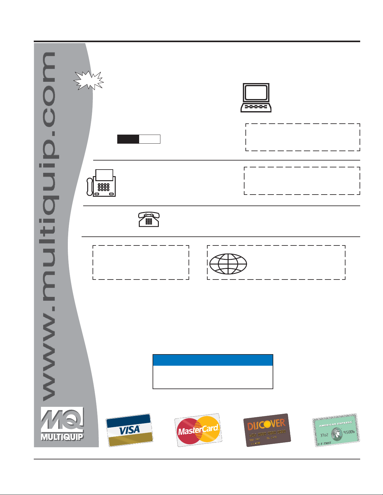
PARTS ORDERING PROCEDURES
Ordering parts has never been easier!
Choose from three easy options:
January 1
Effective:
st
, 2006
Best Deal!
Order via Internet (Dealers Only):
Order parts on-line using Multiquip’s SmartEquip website!
N View Parts Diagrams
N Order Parts
N Print Specification Information
Goto www.multiquip.com and click on
Order Parts
Order via Fax (Dealers Only):
All customers are welcome to order parts via Fax.
Domestic (US) Customers dial:
1-800-6-PARTS-7 (800-672-7877)
Non-Dealer Customers:
Contact your local Multiquip Dealer for
parts or call 800-427-1244 for help in
locating a dealer near you.
to log in and save!
Order via Phone:
If you have an MQ Account, to obtain a Username
and Password, E-mail us at: parts@multiquip.
com.
To obtain an MQ Account, contact your
District Sales Manager for more information.
Use the internet and qualify for a 5% Discount
on Standard orders for all orders which include
complete part numbers.*
Note: Discounts Are Subject To Change
Fax your order in and qualify for a 2% Discount
on Standard orders for all orders which include
complete part numbers.*
Note: Discounts Are Subject To Change
Domestic (US) Dealers Call:
1-800-427-1244
International Customers should contact
their local Multiquip Representatives for
Parts Ordering information.
When ordering parts, please supply:
R Dealer Account Number
R Dealer Name and Address
R Shipping Address (if different than billing address)
R Return Fax Number
R Applicable Model Number
R Quantity, Part Number and Description of Each Part
NOTICE
All orders are treated as Standard Orders and will
ship the same day if received prior to 3PM PST.
R Specify Preferred Method of Shipment:
UPS/Fed Ex DHL
N Priority One Tr uck
N Ground
N Next Day
N Second/Third Day
www.multiquip.com
WE ACCEPT ALL MAJOR CREDIT CARDS!
MVC82VE/VEW COMPACTOR • OPERATION AND PARTS MANUAL — REV. #0 (02/05/09) — PAGE 5
Page 6
SAFETY INFORMATION
Do not operate or service the equipment before reading
the entire manual. Safety precautions should be followed
at all times when operating this equipment.
Failure to read and understand the safety
messages and operating instructions could
result in injury to yourself and others.
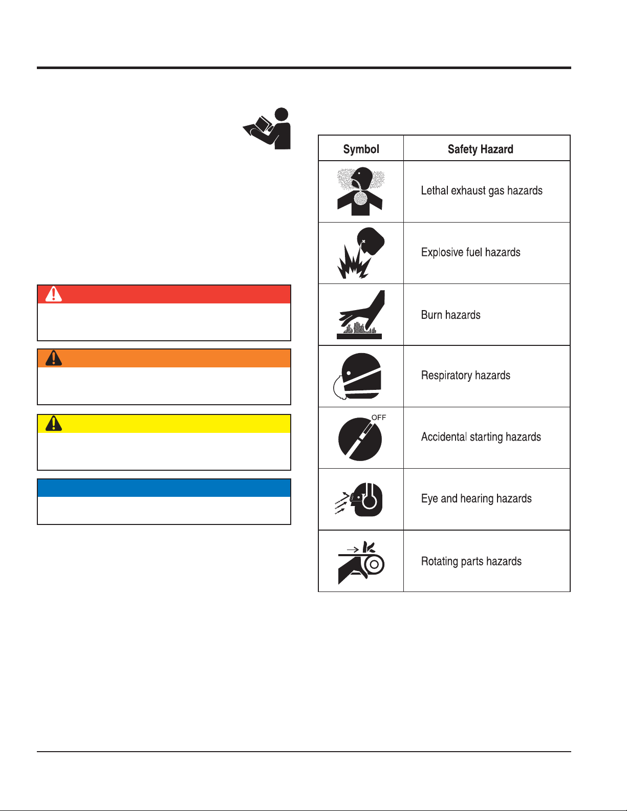
SAFETY MESSAGES
The four safety messages shown below will inform you
about potential hazards that could injure you or others. The
safety messages specifi cally address the level of exposure
to the operator and are preceded by one of four words:
DANGER, WARNING, CAUTION or NOTICE.
SAFETY SYMBOLS
DANGER
Indicates a hazardous situation which, if not avoided,
WILL result in DEATH or SERIOUS INJURY.
WARNING
Potential hazards associated with the operation of this
equipment will be referenced with hazard symbols which
may appear throughout this manual in conjunction with
safety messages.
Indicates a hazardous situation which, if not avoided,
COULD result in DEATH or SERIOUS INJURY.
CAUTION
Indicates a hazardous situation which, if not avoided,
COULD result in MINOR or MODERATE INJURY.
NOTICE
Addresses practices not related to personal injury.
PAGE 6 — MVC82VE/VEW COMPACTOR • OPERATION AND PARTS MANUAL — REV. #0 (02/05/09)
Page 7
SAFETY INFORMATION
GENERAL SAFETY
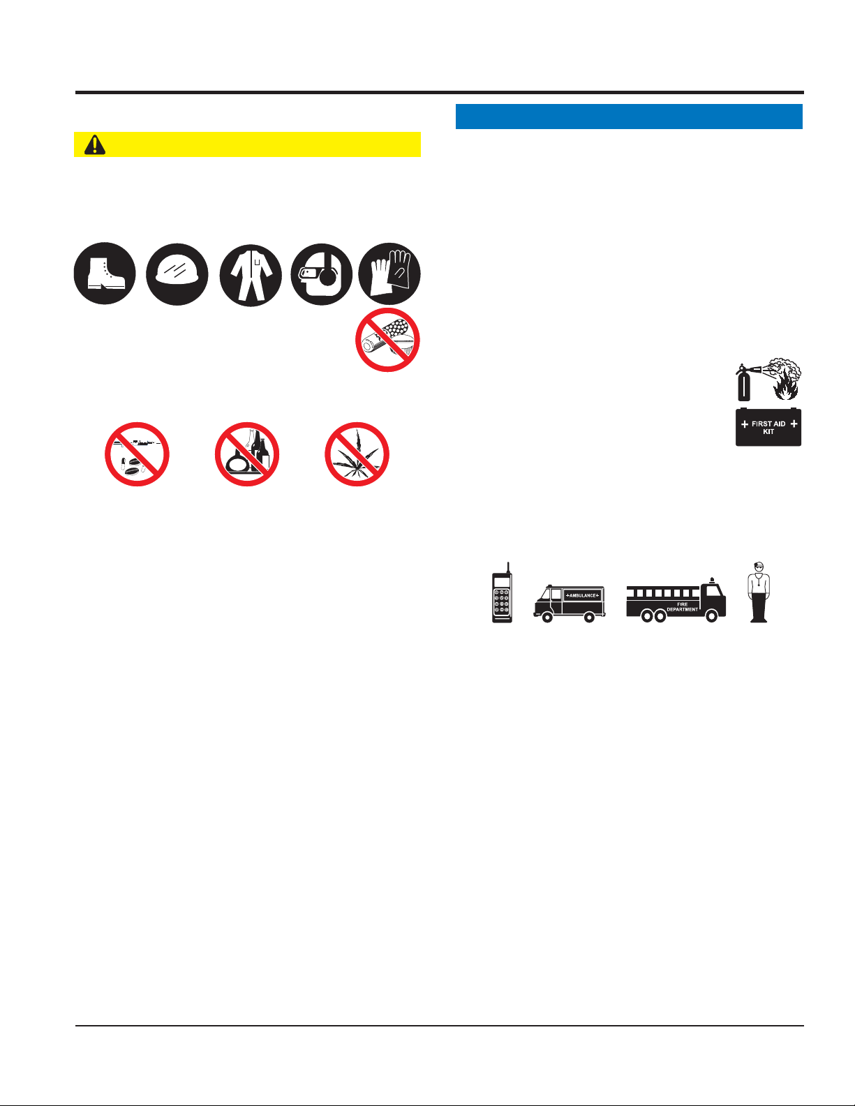
CAUTION
NEVER operate this equipment without proper protective
clothing, shatterproof glasses, respiratory protection,
hearing protection, steel-toed boots and other protective
devices required by the job or city and state regulations.
NEVER operate this equipment when not
feeling well due to fatigue, illness or when
under medication.
NEVER operate this equipment under the infl uence of
drugs or alcohol.
ALWAYS check the equipment for loosened threads or
bolts before starting.
DO NOT use the equipment for any purpose other than
its intended purposes or applications.
NOTICE
This equipment should only be operated by trained and
qualifi ed personnel 18 years of age and older.
Whenever necessary, replace nameplate, operation and
safety decals when they become diffi cult read.
Manufacturer does not assume responsibility for any
accident due to equipment modifi cations. Unauthorized
equipment modifi cation will void all warranties.
NEVER use accessories or attachments that are not
recommended by Multiquip for this equipment. Damage
to the equipment and/or injury to user may result.
ALWAYS know the location of the nearest
fi re extinguisher.
ALWAYS know the location of the nearest
fi rst aid kit.
ALWAYS know the location of the nearest phone or keep
a phone on the job site. Also, know the phone numbers
of the nearest ambulance, doctor and fi re department.
This information will be invaluable in the case of an
emergency.
ALWAYS clear the work area of any debris, tools, etc.
that would constitute a hazard while the equipment is
in operation.
MVC82VE/VEW COMPACTOR • OPERATION AND PARTS MANUAL — REV. #0 (02/05/09) — PAGE 7
Page 8
SAFETY INFORMATION
COMPACTOR SAFETY
DANGER
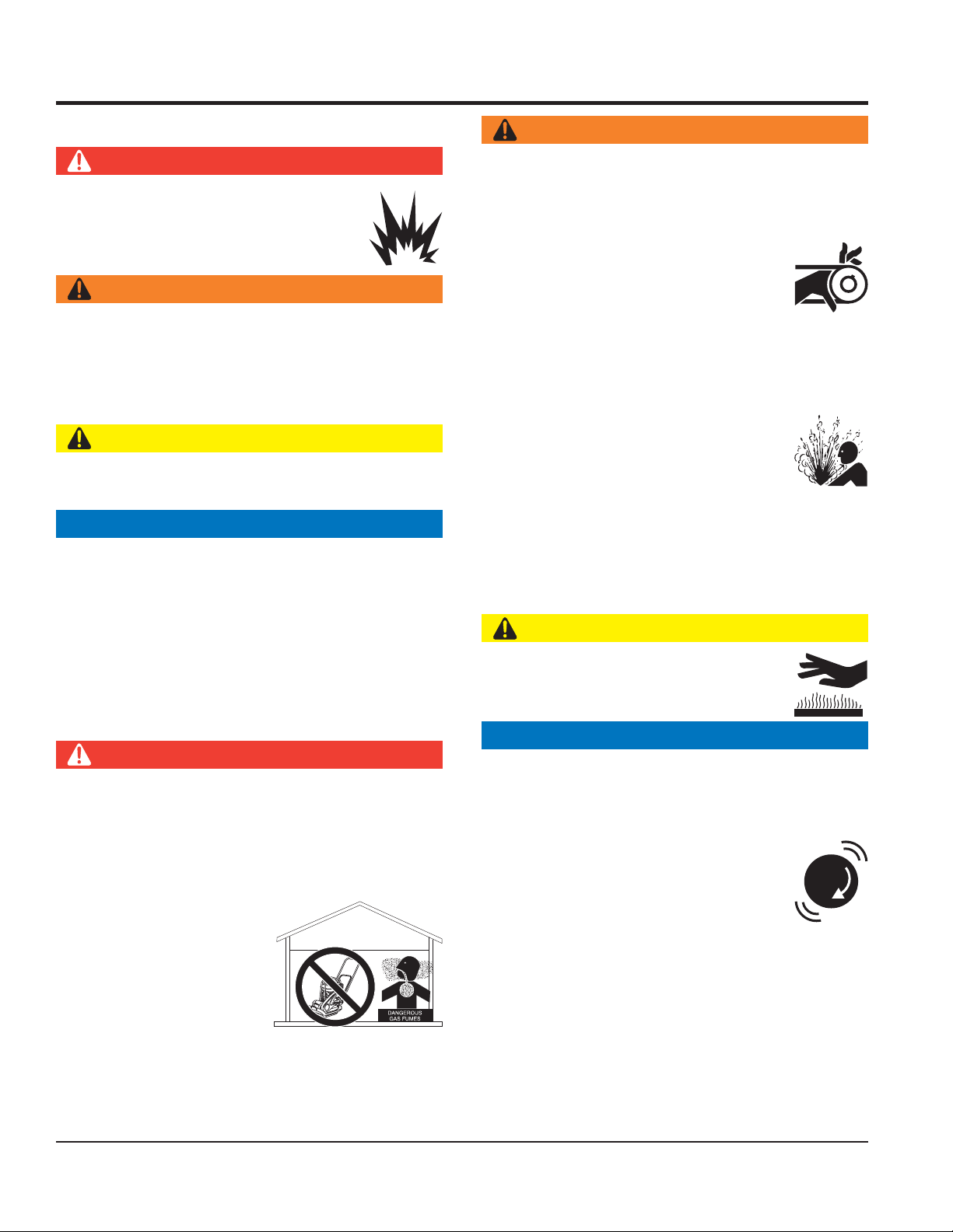
NEVER operate the equipment in an explosive
atmosphere or near combustible materials. An
explosion or fi re could result causing severe
bodily harm or even death.
WARNING
NEVER disconnect any emergency or safety devices.
These devices are intended for operator safety.
Disconnection of these devices can cause severe injury,
bodily harm or even death. Disconnection of any of these
devices will void all warranties.
CAUTION
NEVER lubricate components or attempt service on a
running machine.
NOTICE
ALWAYS keep the machine in proper running condition.
Fix damage to machine and replace any broken parts
immediately.
ALWAYS store equipment properly when it is not being
used. Equipment should be stored in a clean, dry location
out of the reach of children and unauthorized personnel.
ENGINE SAFETY
DANGER
The engine fuel exhaust gases contain poisonous carbon
monoxide. This gas is colorless and odorless, and can
cause death if inhaled.
The engine of this equipment requires an adequate
free fl ow of cooling air. NEVER operate this equipment
in any enclosed or narrow
area where free fl ow of the
air is restricted. If the air
fl ow is restricted it will cause
injury to people and property
and serious damage to the
equipment or engine.
WARNING
DO NOT place hands or fingers inside engine
compartment when engine is running.
NEVER operate the engine with heat shields or
guards removed.
Keep fi ngers, hands hair and clothing away
from all moving parts to prevent injury.
DO NOT remove the radiator cap while the
engine is hot. High pressure boiling water will gush out
of the radiator and severely scald any persons in the
general area of the compactor.
DO NOT remove the coolant drain plug
while the engine is hot. Hot coolant will
gush out of the coolant tank and severely
scald any persons in the general area of
the compactor.
DO NOT remove the engine oil drain plug while the
engine is hot. Hot oil will gush out of the oil tank and
severely scald any persons in the general area of the
compactor.
CAUTION
NEVER touch the hot exhaust manifold,
muffl er or cylinder. Allow these parts to cool
before servicing equipment.
NOTICE
NEVER run engine without an air fi lter or with a dirty air
fi lter. Severe engine damage may occur. Service air fi lter
frequently to prevent engine malfunction.
NEVER tamper with the factory settings
of the engine or engine governor. Damage
to the engine or equipment can result
if operating in speed ranges above the
maximum allowable.
NEVER tip the engine to extreme angles during lifting as
it may cause oil to gravitate into the cylinder head, making
the engine start diffi cult.
PAGE 8 — MVC82VE/VEW COMPACTOR • OPERATION AND PARTS MANUAL — REV. #0 (02/05/09)
Page 9
SAFETY INFORMATION
FUEL SAFETY
DANGER
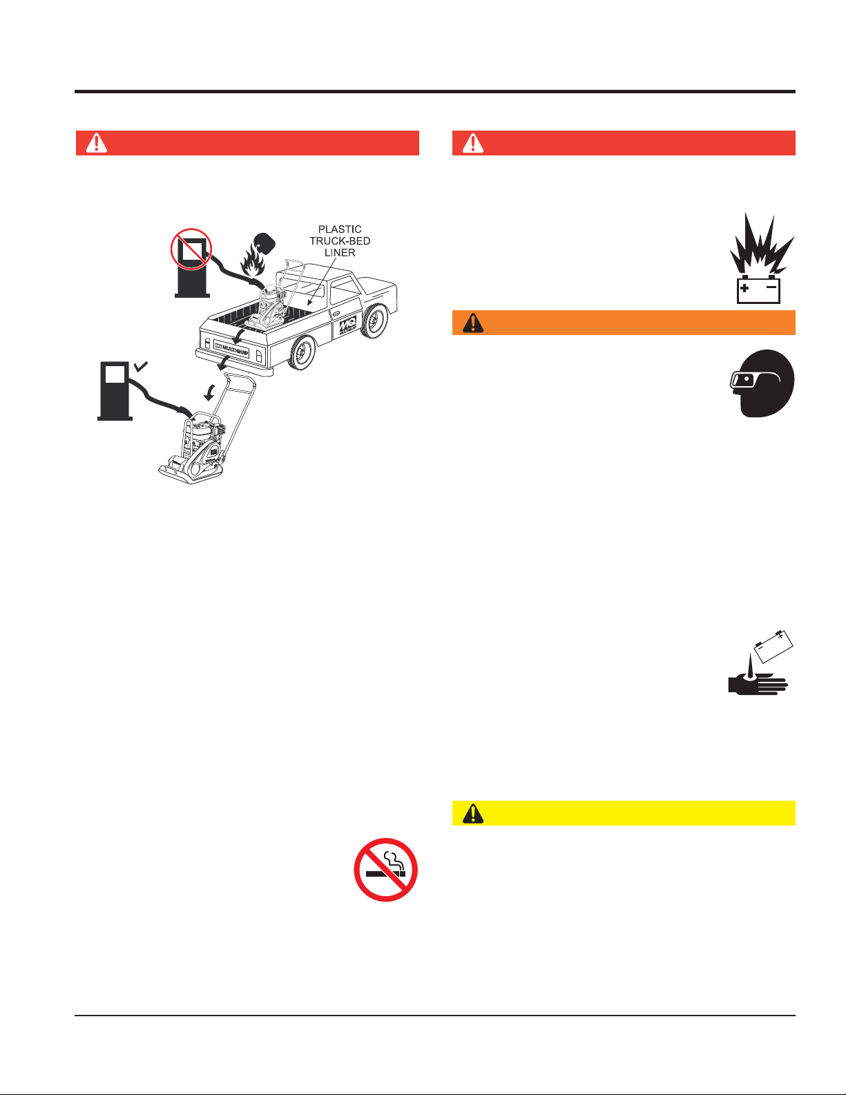
DO NOT add fuel to equipment if it is placed inside truck
bed with plastic liner. Possibility exists of explosion or
fi re due to static electricity.
FUEL
FUEL
DO NOT start the engine near spilled fuel or combustible
fl uids. Diesel fuel is extremely fl ammable and its vapors
can cause an explosion if ignited.
ALWAYS refuel in a well-ventilated area, away from
sparks and open fl ames.
ALWAYS use extreme caution when working with
fl ammable liquids.
DO NOT fi ll the fuel tank while the engine is running
or hot.
DO NOT overfi ll tank, since spilled fuel could ignite if it
comes into contact with hot engine parts or sparks from
the ignition system.
Store fuel in appropriate containers, in well-ventilated
areas and away from sparks and fl ames.
BATTERY SAFETY (ELECTRIC START ONLY)
DANGER
DO NOT drop the battery. There is a possibility that the
battery will explode.
DO NOT expose the battery to open fl ames,
sparks, cigarettes, etc. The battery contains
combustible gases and liquids. If these
gases and liquids come into contact with a
fl ame or spark, an explosion could occur.
WARNING
ALWAYS wear safety glasses when
handling the battery to avoid eye irritation.
The battery contains acids that can cause
injury to the eyes and skin.
Use well-insulated gloves when picking up
the battery.
ALWAYS keep the battery charged. If the battery is not
charged, combustible gas will build up.
DO NOT charge battery if frozen. Battery can explode.
When frozen, warm the battery to at least 61°F (16°C).
ALWAYS recharge the battery in a well-ventilated
environment to avoid the risk of a dangerous concentration
of combustible gases.
If the battery liquid (dilute sulfuric acid)
comes into contact with clothing or skin,
rinse skin or clothing immediately with
plenty of water.
If the battery liquid (dilute sulfuric acid) comes into
contact with eyes, rinse eyes immediately with plenty
of water and contact the nearest doctor or hospital to
seek medical attention.
NEVER use fuel as a cleaning agent.
DO NOT smoke around or near the
equipment. Fire or explosion could result
from fuel vapors or if fuel is spilled on a
hot engine.
CAUTION
ALWAYS disconnect the NEGATIVE battery terminal
before performing service on the equipment.
ALWAYS keep battery cables in good working condition.
Repair or replace all worn cables.
MVC82VE/VEW COMPACTOR • OPERATION AND PARTS MANUAL — REV. #0 (02/05/09) — PAGE 9
Page 10

NOTES
PAGE 10 — MVC82VE/VEW COMPACTOR • OPERATION AND PARTS MANUAL — REV. #0 (02/05/09)
Page 11
SPECIFICATIONS
MVC82VE/VEW Specifi cationsTable 1.
Centrifugal Force 3,080 lbf (13.7 kN)
Vibration Frequency 5600 vpm (93.3 Hz)
Traveling Speed 0 to 82 ft/min (0 to 25 m/min)
Plate Size (L x W) 22.4 x 17.7 in (570 x 450 mm)
Max. Area of Compaction 7,262 sq. ft./h (675 sq. meters/h)
Operating Weight (MVC82VE) 181 lbs. (82 kg)
Operating Weight (MVC82VEW) 198 lbs. (90 kg)
Vibrating Oil Capacity 0.15 quart (0.14 liter)
Water Tank Capacity (MVC82VEW) 11.6 quarts (11 liters)
Engine Specifi cationsTable 2.
Model ROBIN EX170D40103
Type
Valve Arrangement OHC
Bore X Stroke
Displacement 10.3 cu. in. (169 cc)
Max Power Output 4.3 HP (4.2 KW) @ 4000 R.P.M.
Fuel Tank Capacity 3.8 quarts (3.6 liters)
Fuel Gasoline
Speed Control Method Centrifugal Flyweight Type
Air-cooled, 4-stroke, slant single cylinder
horizontal shaft, gasoline engine
2.64 in. X 1.89 in.
(67 mm x 48 mm.)
Lube Oil Capacity 0.63 quarts (0.6 liters)
Starting Method Recoil Start
MVC82VE/VEW COMPACTOR • OPERATION AND PARTS MANUAL — REV. #0 (02/05/09) — PAGE 11
Page 12
C
DIMENSIONS
B
D
A
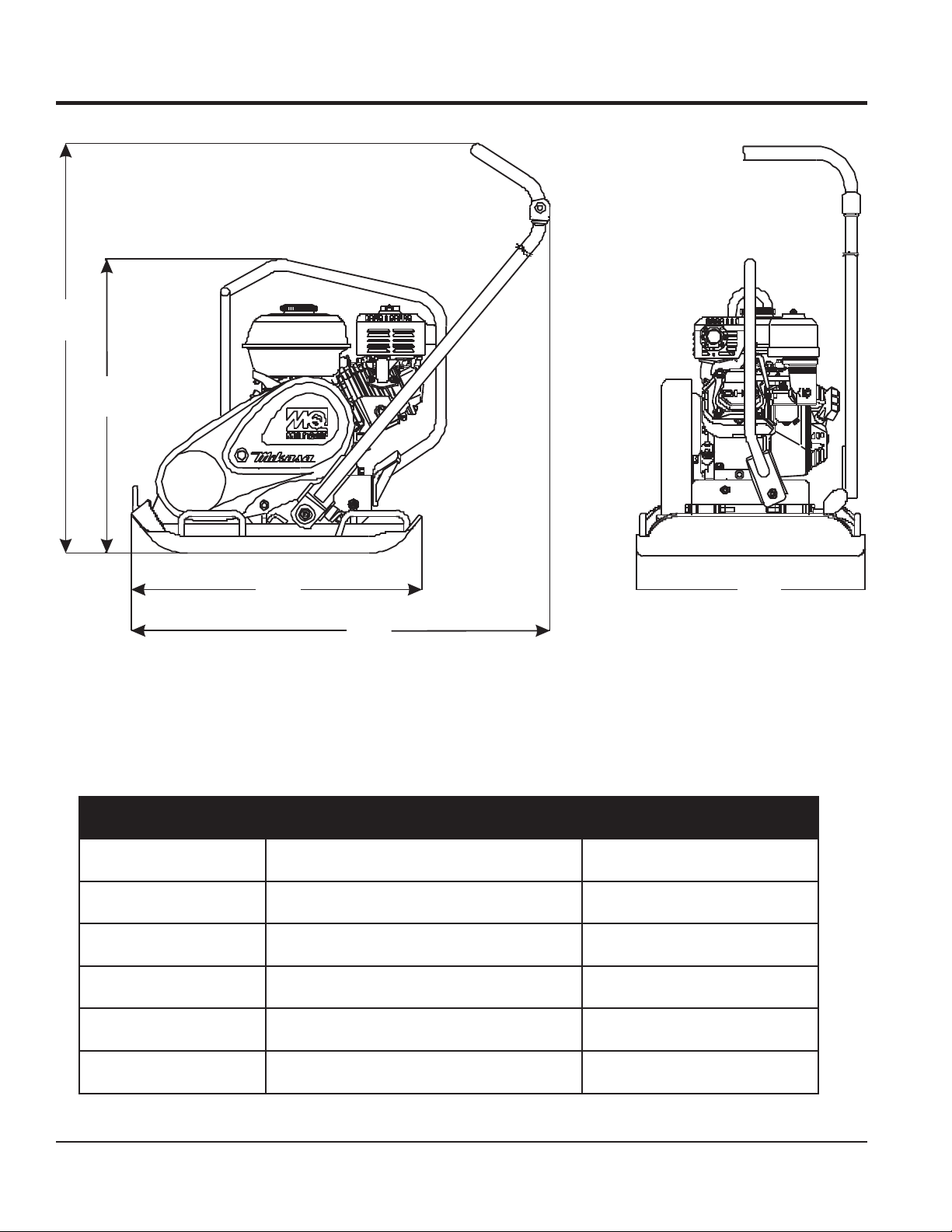
MVC82VE/VEW DimensionsFigure 1.
DimensionsTable 3.
Reference Description Measurement
A Length (including handle) 38.2 in. (970 mm)
B Height (without handle) 22.4 in. (570 mm)
C Height (including handle) 38 in (965 mm)
D Length of Plate 22.4 in (570 mm)
E
E Width of Plate 17.7 in (450 mm)
PAGE 12 — MVC82VE/VEW COMPACTOR • OPERATION AND PARTS MANUAL — REV. #0 (02/05/09)
Page 13

GENERAL INFORMATION
DEFINITION OF PLATE COMPACTOR
The Mikasa MVC82VE/VEW is a walk-behind, one-way
plate compactor designed for the compaction of sand,
mixed soils and asphalt. This plate compactor is a powerful
compacting tool capable of applying a tremendous force in
consecutive high frequency vibrations to a soil surface. Its
applications include soil compacting for road, embankments
and reservoirs as well as backfi lling for gas pipelines, water
pipelines and cable installation work.
VIBRATORY PLATES
The vibratory plates produce low amplitude high frequency
vibrations, designed to compact granular soils and
asphalt.
The resulting vibrations cause forward motion. The engine
and handle are vibration-isolated from the vibrating plate.
The heavier the plate, the more compaction force it
generates.
ANTI-VIBRATION HANDLE SYSTEM (AVT)
This compactor is equipped with advanced anti-vibration
handle design that reduces vibration to the operator by up
to 50% compared to other plate compactors.
FREQUENCY/SPEED
The compactor's vibrating plate has a frequency of 5,600
vpm (vibrations per minute). The travel speed of the
compactor is approximately 82 feet/minute (25 meters/
minute).
ENGINE
The plate compactor is equipped with a Robin EX170D40103
air-cooled, 4-stroke, gasoline engine.
WATER TANK
The MVC82VEW is equippped with a removable plastic
water tank (optional for MVC82VE). The tank provides
lubrication to the base plate when compacting asphalt and
may be used for dust control in dry work environments. It
is intended only for use with water.
DO NOT FILL WITH DIESEL FUEL OR GASOLINE AS
THIS CREATES BOTH A SAFETY AND ENVIRONMENTAL
HAZARD!
MVC82VE/VEW COMPACTOR • OPERATION AND PARTS MANUAL — REV. #0 (02/05/09) — PAGE 13
Page 14
9
COMPONENTS
1
10
4
3
2
WATER TANK
(MVC82VEW ONLY)
8
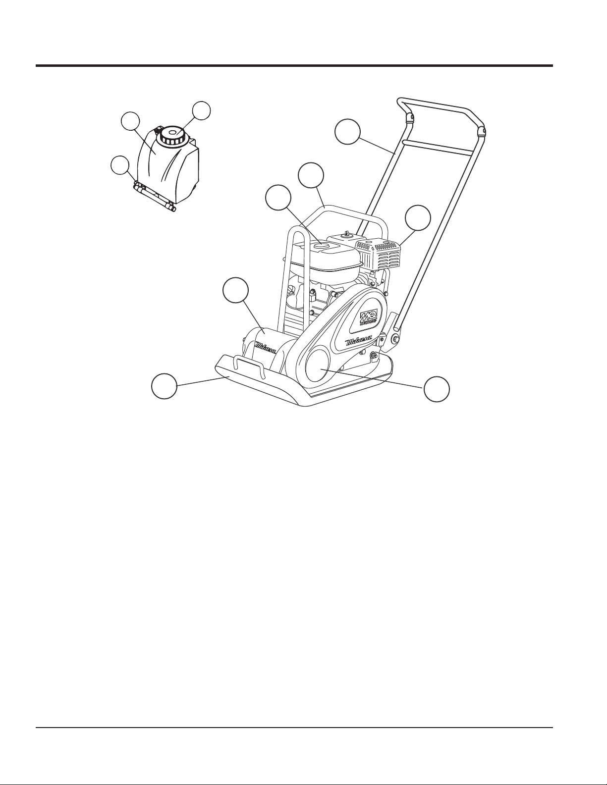
MVC82VE/VEW Controls and ComponentsFigure 2.
Figure 2 shows the location of the basic controls and
components of the MVC82VE/VEW Plate Compactor. The
function of each control is described below:
Water Tank Cap (VEW Only) 1. — Remove this cap to
add water to the water tank.
Fuel Tank Cap 2. — Remove this cap to add fuel.
Lifting Bale 3. — When lifting of the compactor is
required either by forklift, crane, etc., tie rope or chain
around this lifting point.
Handle Bar 4. — When operating the compactor use this
handle bar to maneuver the compactor.
Gasoline Engine 5. — This plate compactor uses a
ROBIN EX170D40103 engine. Refer to the ROBIN
owner's manual for engine information and related
topics.
5
67
Belt Cover 6. — Remove this cover to gain access to the
V-belts. NEVER run the compactor without the V-belt
cover. If the V-belt cover is not installed, the possibility
exists that your hand may get caught between the V-belt
and clutch, causing serious injury and bodily harm.
Vibrating Plate 7. — A fl at, open plate made of durable
cast iron construction used in the compacting of soil.
Vibration Case 8. — Encloses the eccentric, gears and
counter weights.
Water Shut-Off Valve (VEW only) 9. — Turn this valve
downward to let water fl ow from the water tank to the
water tube.
Water Tank (VEW only) 10. — Holds 11.6 quarts of
water (removable, no tools required). DO NOT FILL
WITH DIESEL FUEL OR GASOLINE AS THIS
CREATES BOTH A SAFETY AND ENVIRONMENTAL
HAZARD!
PAGE 14 — MVC82VE/VEW COMPACTOR • OPERATION AND PARTS MANUAL — REV. #0 (02/05/09)
Page 15
BASIC ENGINE
1
10
9
2
8
7
6
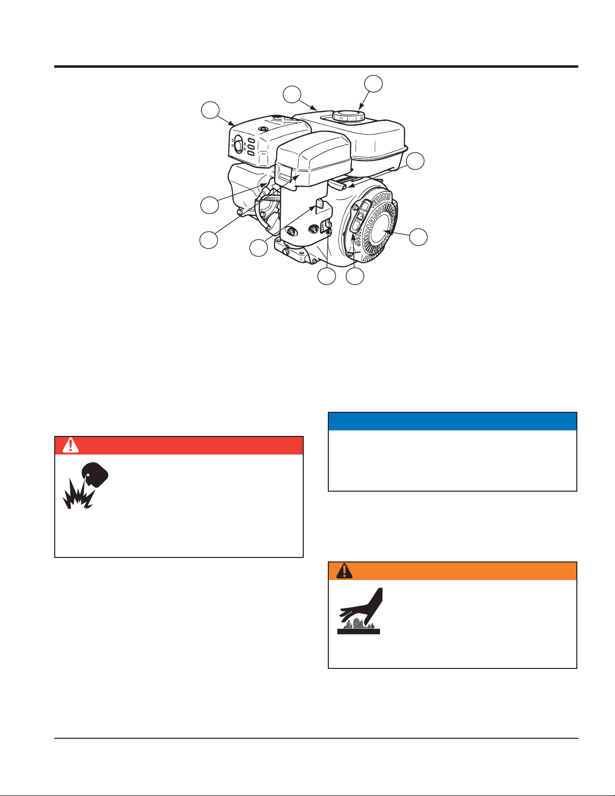
Robin Engine ComponentsFigure 3.
The engine (Figure 3) must be checked for proper
lubrication and fi lled with fuel prior to operation. Refer
to the manufacturer's engine manual for instructions and
details of operation and servicing.
Fuel Filler Cap 1. — Remove this cap to add unleaded
gasoline to the fuel tank. Make sure cap is tightened
securely. DO NOT over fi ll.
DANGER
Adding fuel to the tank should be done
only when the engine is stopped and has
had an opportunity to cool down. In the
event of a fuel spill, DO NOT attempt to
start the engine until the fuel residue has
been completely wiped up and the area surrounding
the engine is dry.
3
5
4
Choke Lever 6. — Used in the starting of a cold engine,
or in cold weather conditions. The choke enriches the
fuel mixture.
Air Cleaner 7. — Prevents dirt and other debris from
entering the fuel system. Remove wing-nut on top of
air fi lter canister to gain access to fi lter element.
NOTICE
Operating the engine without an air filter, with a
damaged air fi lter, or a fi lter in need of replacement
will allow dirt to enter the engine, causing rapid engine
wear.
Spark Plug 8. — Provides spark to the ignition system.
Set spark plug gap to 0.6 - 0.7 mm (0.028 - 0.031 inch).
Clean spark plug once a week.
Muffl er 9. — Used to reduce noise and emissions.
Throttle Lever 2. — Used to adjust engine RPM speed
(lever advanced forward - SLOW, lever back toward
operator - FAST).
Engine ON/OFF Switch 3. — ON position permits engine
starting, OFF position stops engine operations.
Recoil Starter (pull rope) 4. — Manual-starting method.
Pull the starter grip until resistance is felt, then pull
briskly and smoothly.
WARNING
Engine components can generate extreme
heat. To prevent burns, DO NOT touch
these areas while the engine is running
or immediately after operating. NEVER
operate the engine with the muffler
removed.
Fuel Tank 10. — Holds unleaded gasoline. For additional
information refer to engine owner's manual.
Fuel Valve Lever 5. — OPEN to let fuel fl ow, CLOSE to
stop the fl ow of fuel.
MVC82VE/VEW COMPACTOR • OPERATION AND PARTS MANUAL — REV. #0 (02/05/09) — PAGE 15
Page 16
INSPECTION
BEFORE STARTING
Read safety instructions at the beginning of manual.1.
Clean the compactor, removing dirt and dust, 2.
particularly the engine cooling air inlet, carburetor and
air cleaner.
Check the air fi lter for dirt and dust. If air fi lter is dirty, 3.
replace air fi lter with a new one as required.
Check carburetor for external dirt and dust. Clean with 4.
dry compressed air.
Check fastening nuts and bolts for tightness. Loosened 5.
screws or bolts due to vibration, could lead to
unexpected accident.
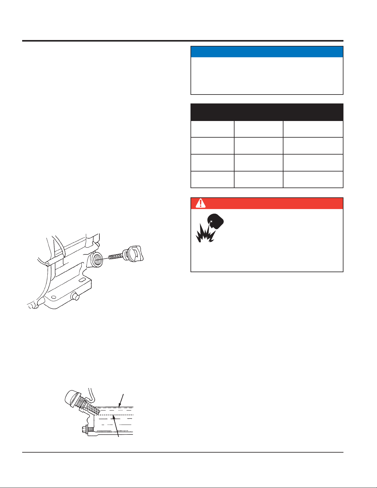
ENGINE OIL CHECK
To check the engine oil level, place the pump on secure 1.
level ground with the engine stopped.
Remove the fi ller dipstick from the engine oil fi ller hole 2.
(Figure 4) and wipe clean.
NOTICE
The Oil Alert System will automatically stop the engine
before the engine falls below safe limits. Always be
sure to check the engine oil level prior to starting the
engine.
Oil TypeTable 4.
Season Temperature Oil Type
Summer 25° C or higher SAE 10W-30
Spring/Fall 25° C - 10° C SAE 10W-30/20
Winter 0° C SAE 10W-10
DANGER
Adding fuel to the tank should be done
only when the engine is stopped and has
had an opportunity to cool down. In the
event of a fuel spill, DO NOT attempt to
start the engine until the fuel residue has
been completely wiped up and the area surrounding
the engine is dry.
FUEL CHECK
Remove the gasoline cap located on top of fuel tank.5.
Visually inspect to see if the fuel level is low. If fuel is 6.
Engine Oil Dipstick (Removal)Figure 4.
Insert and remove the dipstick without screwing it 3.
into the fi ller neck. Check the oil level shown on the
dipstick.
If the oil level is low (Figure 5), fi ll to the edge of the oil 4.
fi ller hole with the recommended oil type (Table 4).
Maximum oil capacity is 0.63 quarts (0.60 liters).
Engine Oil Dipstick (Oil Level)Figure 5.
PAGE 16 — MVC82VE/VEW COMPACTOR • OPERATION AND PARTS MANUAL — REV. #0 (02/05/09)
low, replenish with unleaded fuel.
When refueling, be sure to use a strainer for fi ltration. 7.
DO NOT top-off fuel. Wipe up any spilled fuel
immediately!
Page 17
INSPECTION
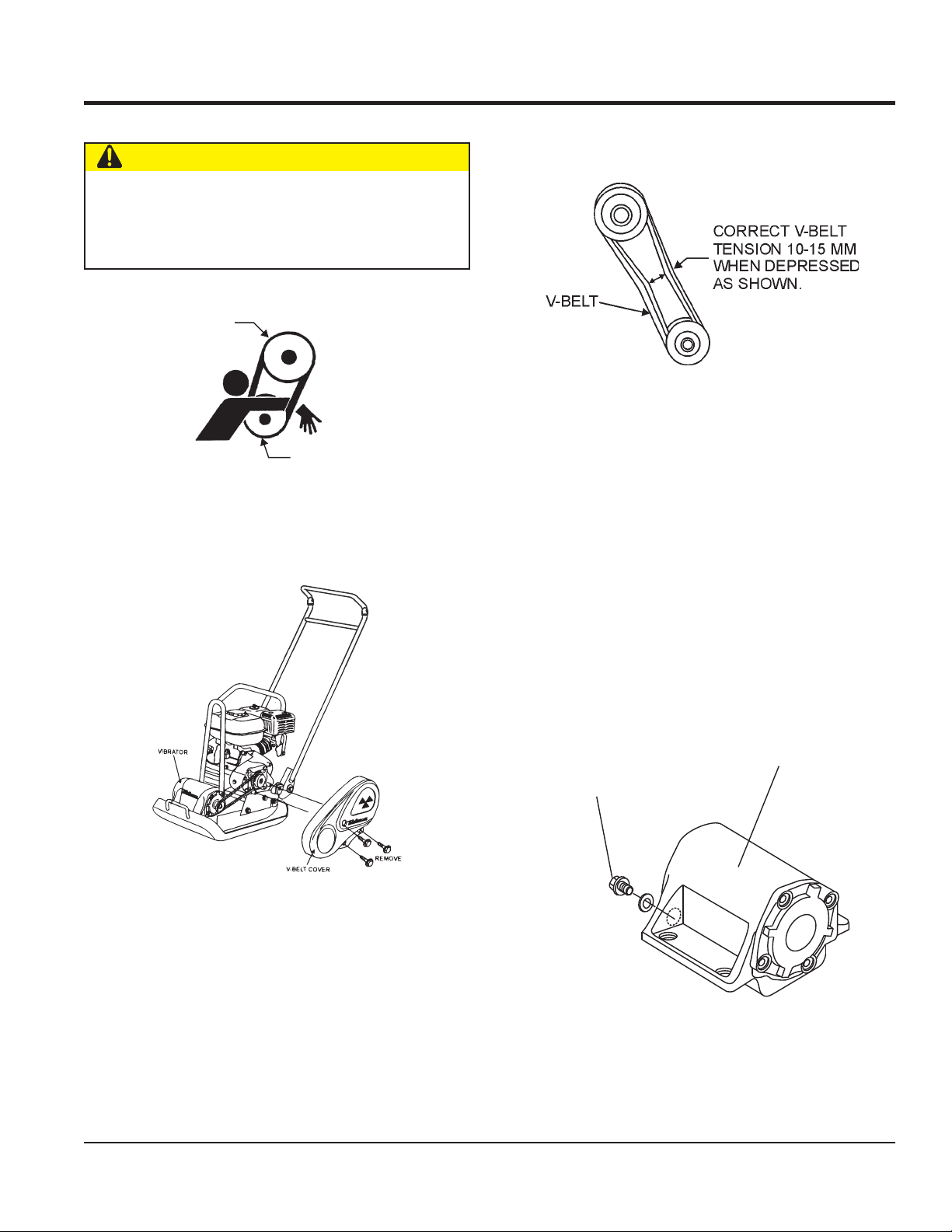
V-BELT CHECK
CAUTION
NEVER attempt to check the V-belt with the engine
running. Severe injury can occur if your hand (Figure 6)
gets caught between the V-belt and the clutch. Always
use safety gloves.
CLUTCH
PULLEY
VIBRATOR
PULLEY
V-Belt HazardFigure 6.
To check the V-belt tension, remove the three bolts that 1.
secure the belt cover to the frame as shown in
Figure 7.
The V-belt tension is proper if the V-belt bends 10 to 2.
15 mm (Figure 8) when depressed with fi nger midway
between the clutch and vibration pulley shafts.
V-Belt TensionFigure 8.
A loose V-belt will decrease the power transmission 3.
output causing reduced compaction and premature
wear of the belt.
If the V-belt becomes worn or loose, replace it.4.
VIBRATOR OIL CHECK
Place the plate compactor horizontally on a fl at surface. 1.
Make sure the compactor is level when checking the
oil in the vibrator assembly.
Check vibrator oil level by removing the oil plug 2.
(vibrator oil gauge) as shown in Figure 9. The oil level
should be up to the oil plug. The vibrator holds 140 cc
(approximately 0.3 pint). If oil is required, replace using
only SAE10W-30 motor oil.
VIBRATOR
OIL PLUG
V-Belt Cover RemovalFigure 7.
Vibrator Oil PlugFigure 9.
MVC82VE/VEW COMPACTOR • OPERATION AND PARTS MANUAL — REV. #0 (02/05/09) — PAGE 17
Page 18
OPERATION
CAUTION
DO NOT attempt to run the compactor
until the Safety and Initial Start-up sections
have been read and understood.
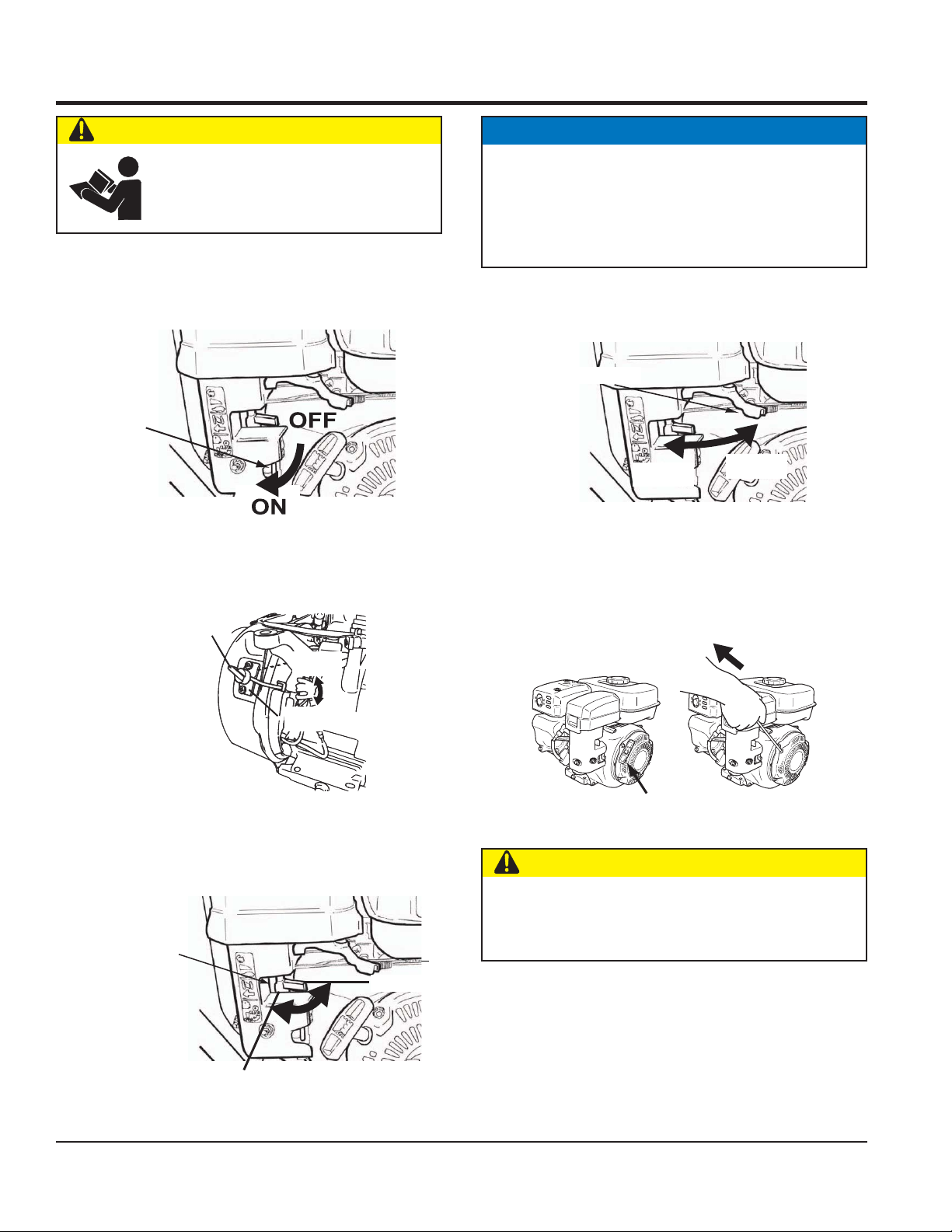
INITIAL STARTUP
Place the fuel valve lever (Figure 10) in the "ON" 1.
position.
FUEL
LEVER
Place the Engine ON/OFF switch (Figure 11) in the 2.
"ON" position.
ENGINE
ON/OFF
SWITCH
NOTICE
The CLOSED position of the choke lever enriches the
fuel mixture for starting a COLD engine. The OPEN
position provides the correct fuel mixture for normal
operation after starting, and for restarting a warm
engine.
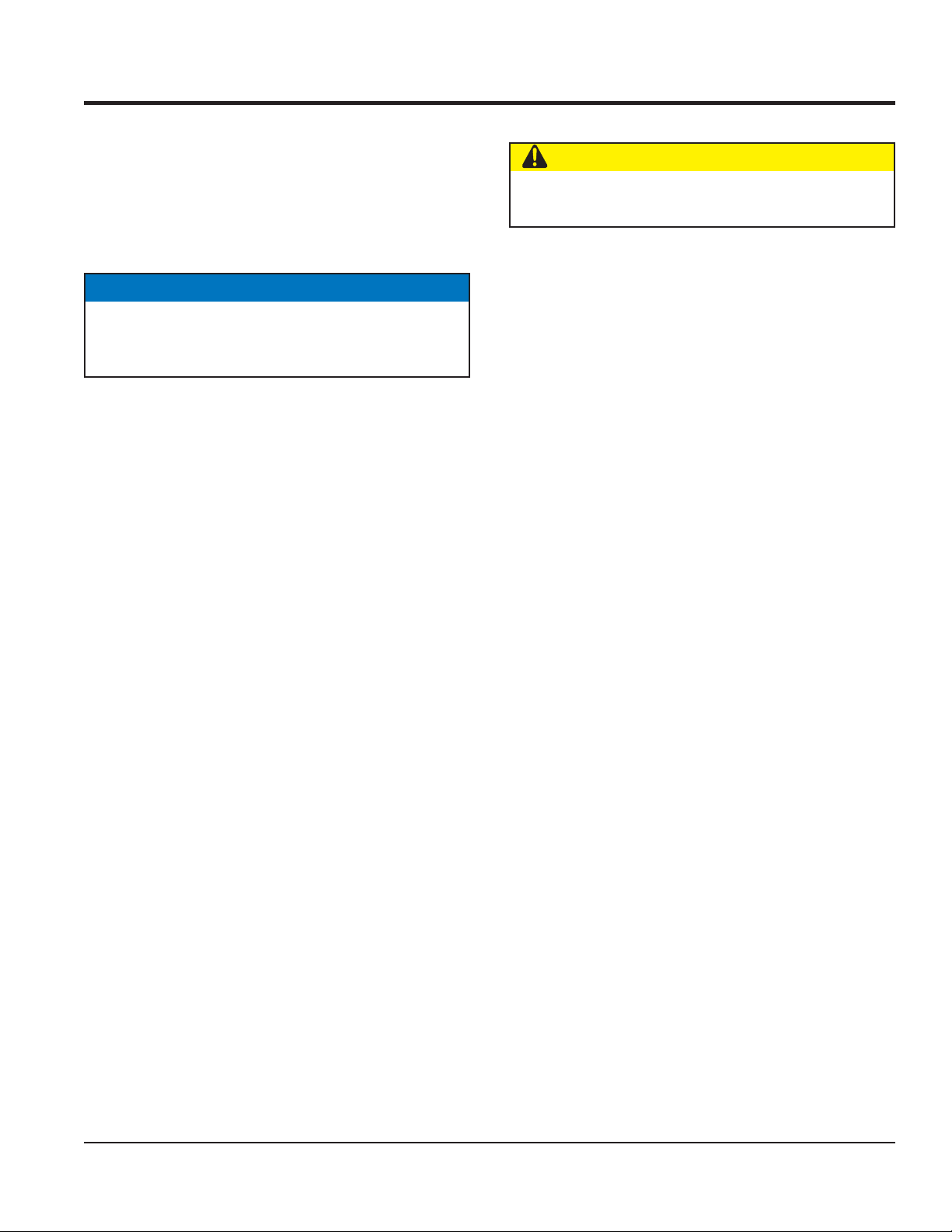
Place the throttle lever (Figure 13) halfway between 4.
fast and slow.
THROTTLE
LEVER
FAST
Fuel Valve LeverFigure 10.
Throttle LeverFigure 13.
SLOW
Grasp the starter grip (Figure 14) and slowly pull it out. 5.
The resistance becomes the hardest at a certain
position, corresponding the compression point. Rewind
the rope a little from that point and pull out sharply.
OFF
ON
STARTER GRIP
Engine ON/Off SwitchFigure 11.
Place the Choke Lever (Figure 12) in the "OPEN" 3.
CAUTION
position.
DO NOT pull the starter rope all the way to the end.
CHOKE
LEVER
Nnnn
OPEN
DO NOT release the starter rope after pulling. Allow it
to rewind as soon as possible.
If the engine has started, slowly return the choke lever 6.
(Figure 11) to the CLOSED position. If the engine has
not started repeat steps 1 through 5.
Before the compactor is put into operation run the 7.
CLOSED
Choke LeverFigure 12.
engine for 3-5 minutes.
Check for abnormal engine noises or fuel leaks.8.
PAGE 18 — MVC82VE/VEW COMPACTOR • OPERATION AND PARTS MANUAL — REV. #0 (02/05/09)
Starter GripFigure 14.
Page 19
OPERATION
OPERATION
Once the engine has started, move the engine throttle 1.
lever quickly to the fast position.
With the throttle lever in the fast position, the engine 2.
speed should be around 2,300 RPM, therefore
engaging the centrifugal clutch.
NOTICE
ALWAYS move the throttle lever quickly without
hesitation, because increasing the engine speed slowly
causes the clutch to slip.
Firmly grasp the compactor's handle bar with both 3.
hands. The compactor will begin moving forward.
Slowly walk behind the compactor and be on the lookout 4.
for any large objects or foreign matter that might cause
damage to the compactor or bodily injury.
Compactor traveling speed may drop on soils which 5.
contain clay, however there may be cases where
traveling speed drops because the compaction plate
does not leave the ground surface easily due to the
composition of the soil. To rectify this problem, do the
following:
STOPPING THE ENGINE
CAUTION
NEVER stop the engine suddenly while working at
high speeds.
Place the throttle lever (Figure 13) in slow position, and 1.
listen for the engine speed to decrease.
Place the Engine ON/OFF switch (Figure 11) in the 2.
"OFF" position.
Place the fuel valve lever (Figure 10) in the "3. OFF"
position.
Check the bottom plate to see if clay or equivalent •
material has been lodged in the plate mechanism. If
so, wash with water and remove.
Remember the compactor does not work as effi ciently •
on clay or soils that have a high moisture content
level.
If the soil has a high moisture level, dry soil to •
appropriate moisture content level or carry out
compaction twice.
MVC82VE/VEW COMPACTOR • OPERATION AND PARTS MANUAL — REV. #0 (02/05/09) — PAGE 19
Page 20

MAINTENANCE
CAUTION
Inspection and other services should always be carried
out on hard and level ground with the engine shut
down.
INSPECTION AND MAINTENANCE TABLES
To make sure your plate compactor is always in good
working condition before using, carry out the maintenance
inspection in accordance with Tables 5 and 6.
Machine InspectionTable 5.
Item Frequency of Inspection
Loose or Missing Screws Every 8 hours (daily)
Damaged Parts Every 8 hours (daily)
Function of Controlling
System Part
Every 100 hours
Engine CheckTable 6.
Item Frequency of Inspection
Oil or Fuel Leak Every 8 hours (daily)
Tightness of Fastening
Threads
Engine Oil Check and
Replenishment
Engine Oil Replacement
Valve Clearance
(Check/Adjust)
Every 8 hours (daily)
Every 8 hours (daily)
(Replenish to specifi ed
maximum level)
After fi rst 25 hours then
every 50 to 100 hours
After fi rst 25 hours then
every 200 hours or every
year.
Air Filter Cleaning Every 100 hours
Vibrator Oil Check Every 100 hours
Vibrator Oil Replacement Every 300 hours
Hydraulic Oil Check Every 100 hours
Hydraulic Oil
Replacement
After fi rst 200 hours, then
every 1,000 hours
V-belt (clutch) Check Every 200 hours
NOTICE
These inspection intervals are for operation under
normal conditions. Adjust your inspection intervals
based on the number of hours the plate compactor
has been in use, and the type of working conditions it
is being used.
NOTICE
Fuel piping and connections should be replaced every
2 years.
See separate engine manual for details on engine check.
DAILY SERVICE
Check for leakage of fuel or oil.1.
Check for loose screws including tightness. See Table 7 2.
(Tightening Torque) for retightening.
Tightening Torque (kg cm)Table 7.
Diameter
Material
6mm 8mm 10mm 12mm 14mm 16mm 18mm 20mm
4T 70 150 300 500 750 1,100 1,400 2,000
6-8T 100 250 500 800 1,300 2,000 2,700 3,800
11T 150 400 800 1,200 2,000 2,900 4,200 5,600
300-
350
650-
700
100
*
* (for aluminum counterpart)
(Threads in use with this machine are all right-handed)
Material and quality of material is marked on each bolt and screw.
PAGE 20 — MVC82VE/VEW COMPACTOR • OPERATION AND PARTS MANUAL — REV. #0 (02/05/09)
Page 21

MAINTENANCE
Remove soil and clean the bottom of compaction 3.
plate.
Check hydraulic pump, piping and hose for any leakage. 4.
A loosened hydraulic hose can be a cause for leakage.
Check hydraulic hose connections with wrench applied
for tightness.
Check engine oil.5.
ENGINE OIL REPLACEMENT
Replace engine oil, in fi rst 20 hours of operation and 1.
every 100 hours afterwards.
Oil may be drained more easily when it is warm after 2.
operation (For more details, see separate engine
Owner's Manual).
AIR FILTER
Remove the air cleaner cover and foam fi lter element 1.
as shown in Figure 15.
Clean foam element in warm, soapy water or 3.
nonfl ammable solvent. Rinse and dry thoroughly. Dip
the element in clean engine oil and completely squeeze
out the excess oil from the element before installing.
CHECKING AND REPLACING V-BELT AND CLUTCH
After 200 hours of operation, remove the upper belt cover to
check the V-belt tension. Tension is proper if the belt bends
about 10 mm when depressed strongly with fi nger between
shafts. Loose or worn V-belts reduce power transmission
effi ciency, causing weak compaction and reducing the life
of the belt itself.
Replacing the V-belt
Remove the upper and lower belt covers. Engage an
offset wrench (13 mm) or the like to vibrator pulley (lower)
fastening bolt. Engage waste cloth or the like at midway
of V-belt on the left side and while pulling it back strongly,
rotate the offset wrench clockwise so that the V-belt will
come off.
Reinstalling the V-belt
Air FilterFigure 15.
Tap the paper fi lter element (Figure 15) several times on 2.
a hard surface to remove dirt, or blow compressed air
[not exceeding 30 psi (207 kPa, 2.1 kgf/cm2)] through
the fi lter element from the air cleaner case side.
Engage V-belt to lower vibrator pulley and push the V-belt
to left side of upper clutch. In the same manner as in
removal, rotate offset wrench clockwise so that the V-belt
goes back on.
Checking Clutch
Check the clutch simultaneously with V-belt checking. With
belt removed, visually check outer drum of the clutch for
seizure and "V" groove for wear or damage. Clean the "V"
groove as necessary. Regularly check the lining or shoe
for wear. If the shoe is worn, power transmission becomes
defi cient and slipping will result.
NOTICE
Whenever the compactor's vibration becomes weak or
lost during normal operation, regardless of operation
hours, check the V-belt and clutch immediately.
MVC82VE/VEW COMPACTOR • OPERATION AND PARTS MANUAL — REV. #0 (02/05/09) — PAGE 21
Page 22

MAINTENANCE
VIBRATOR OIL LEVEL CHECK
In every 300 hours of operation, with the machine 1.
positioned horizontally, remove vibrator oil level check
plug (Figure 6) off vibrator (14 mm wrench) and see
if oil is up to fi ller port. Be sure to clean area around
check hole to prevent dirt and dust from entering.
In every 300 hours of operation, replace oil (capacity 2.
400 cc). For draining oil through level check hole, have
the machine inclined with a sleeper or the like placed
under the compaction plate on opposite side.
* Use engine oil 10W-30 for this lubrication.
NOTICE
Always clean the area around the vibrator oil level check
hole before removing oil check plug. This will prevent
dirt and debris from entering the system.
SPARK PLUG
Remove and clean the spark plug (Figure 16).3.
PLATE COMPACTOR STORAGE
For storage of the plate compactor for over 30 days, the
following is required:
Drain the fuel tank completely or add STA-BIL to the 1.
fuel.
Run the engine until the fuel is completely 2.
consumed.
Completely drain the oil from the engine crankcase 3.
and follow procedures described in the engine Owner's
Manual for engine storage.
Completely drain the compactor's hydraulic oil from 4.
the vibrating case.
Clean entire plate compactor, especially the bottom 5.
plate removing all dirt and foreign matter.
Cover plate compactor and engine with plastic covering 6.
or equivalent and store in a clean, dry place.
Spark Plug GapFigure 16.
Adjust the spark gap to 0.028 ~0.031 inch 4.
(0.7~0.8 mm).
PAGE 22 — MVC82VE/VEW COMPACTOR • OPERATION AND PARTS MANUAL — REV. #0 (02/05/09)
Page 23

TROUBLESHOOTING
Engine TroubleshootingTable 8.
Symptom Possible Cause Solution
Spark plug bridging? Check gap, insulation or replace spark plug.
Diffi cult to start. Fuel is
available but no SPARK
at spark plug.
Diffi cult to start. Fuel is
available and SPARK
is present at the spark
plug.
Diffi cult to start. Fuel
is available, SPARK is
present at the spark
plug and compression
is normal.
Diffi cult to start. Fuel
is available, SPARK is
present at the spark
plug and compression
is low.
Carbon deposit on spark plug? Clean or replace spark plug.
Short circuit due to defi cient spark plug
insulation?
Improper spark plug gap? Set to proper gap.
ON/OFF switch is shorted? Check switch wiring. Replace switch.
Ignition coil defective? Replace ignition coil.
Improper spark gap, points dirty? Set correct spark gap and clean points.
Condenser insulation worn or short
circuiting?
Spark plug wire broken or short circuiting? Replace defective spark plug wiring.
Wrong fuel type?
Water or dust in fuel system? Flush fuel system.
Air cleaner dirty? Clean or replace air cleaner.
Suction/exhaust valve stuck or protruded? Reseat valves.
Piston ring and/or cylinder worn? Replace piston rings or piston.
Cylinder head and/or spark plug not
tightened properly?
Head gasket and/or spark plug gasket
damaged?
Check spark plug insulation. Replace if
worn.
Replace condenser.
Flush fuel system and replace with correct
type of fuel.
Torque cylinder head bolts and spark plug.
Replace head and spark plug gaskets.
Fuel not available in fuel tank? Fill with correct type of fuel.
Fuel cock does not open properly?
No fuel present at
carburetor.
Weak in power.
Compression is proper
and does not misfi re.
MVC82VE/VEW COMPACTOR • OPERATION AND PARTS MANUAL — REV. #0 (02/05/09) — PAGE 23
Fuel fi lter clogged? Replace fuel fi lter.
Fuel tank cap breather hole clogged? Clean or replace fuel tank cap.
Air in fuel line? Bleed fuel line
Air cleaner dirty? Clean or replace air cleaner.
Improper level in carburetor? Check fl oat adjustment. Rebuild carburetor.
Defective spark plug? Clean or replace spark plug.
Apply lubricant to loosen fuel cock lever.
Replace if necessary.
Page 24

TROUBLESHOOTING
CONTINUED...
Symptom Possible Cause Solution
Weak in power.
Compression is proper
but misfi res.
Engine overheats.
Rotational speed
fl uctuates.
Recoil starter
malfunction.
Symptom Possible Problem Solution
Water in fuel system?
Dirty spark plug? Clean or replace spark plug
Ignition coil defective? Replace ignition coil.
Spark plug heat value improper? Replace with correct type of spark plug.
Incorrect type of fuel? Replace with correct type of fuel.
Cooling fi ns dirty? Clean cooling fi ns.
Governor adjusted correctly? Adjust governor
Governor spring defective? Replace governor spring.
Fuel fl ow restricted? Check entire fuel system for leaks or clogs.
Recoil mechanism clogged with dust and
dirt?
Spiral spring loose? Replace spiral spring.
Plate Compactor TroubleshootingTable 9.
Engine speed too low? Set engine speed to correct RPM.
Flush fuel system and replace with correct
type of fuel.
Clean recoil assembly with soap and water.
Travel speed too low
and vibration is weak.
Clutch slips? Check or replace clutch.
V-belt slips? Adjust or replace V-belt.
Excessive oil in vibrator? Drain excess oil and fi ll to proper level.
Malfunction in vibrator housing? Check eccentric, gears and counter weights.
Bearing Failure? Replace bearing.
Insuffi cient engine output? Check engine, compression.
PAGE 24 — MVC82VE/VEW COMPACTOR • OPERATION AND PARTS MANUAL — REV. #0 (02/05/09)
Page 25

NOTES
MVC82VE/VEW COMPACTOR • OPERATION AND PARTS MANUAL — REV. #0 (02/05/09) — PAGE 25
Page 26

EXPLANATION OF CODE IN REMARKS COLUMN
r
r
The following section explains the different symbols and
remarks used in the Parts section of this manual. Use the
help numbers found on the back page of the manual if there
are any questions.
NOTICE
The contents and part numbers listed in the parts
section are subject to change without notice. Multiquip
does not guarantee the availability of the parts listed.
SAMPLE PARTS LIST
NO. PART NO. PART NAME QTY. REMARKS
1 12345 BOLT ......................1 .....INCLUDES ITEMS W/%
2% WASHER, 1/4 IN. ...........NOT SOLD SEPARATELY
2% 12347 WASHER, 3/8 IN. ...1 .....MQ-45T ONLY
3 12348 HOSE ..................A/R ...MAKE LOCALLY
4 12349 BEARING ..............1 .....S/N 2345B AND ABOVE
NO. Column
Unique Symbols — All items with same unique
symbol
QTY. Column
Numbers Used — Item quantity can be indicated by a
number, a blank entry, or A/R.
A/R (As Required) is generally used for hoses or othe
parts that are sold in bulk and cut to length.
A blank entry generally indicates that the item is not sold
separately. Other entries will be clarified in the “Remarks”
Column.
REMARKS Column
Some of the most common notes found in the “Remarks”
Column are listed below. Other additional notes needed
to describe the item can also be shown.
Assembly/Kit — All items on the parts list with the
same unique symbol will be included when this item is
purchased.
Indicated by:
“INCLUDES ITEMS W/(unique symbol)”
(@, #, +, %, or >) in the number column belong to the
same assembly or kit, which is indicated by a note in the
“Remarks” column.
Duplicate Item Numbers — Duplicate numbers indicate
multiple part numbers, which are in effect for the same
general item, such as different size saw blade guards in
use or a part that has been updated on newer versions
of the same machine.
NOTICE
When ordering a part that has more than one item
number listed, check the remarks column for help in
determining the proper part to order.
PART NO. Column
Numbers Used — Part numbers can be indicated by a
number, a blank entry, or TBD.
TBD (To Be Determined) is generally used to show a
part that has not been assigned a formal part number
Serial Number Break — Used to list an effective serial
number range where a particular part is used.
Indicated by:
“S/N XXXXX AND BELOW”
“S/N XXXX AND ABOVE”
“S/N XXXX TO S/N XXX”
Specific Model Number Use — Indicates that the part
is used only with the specific model number or model
number variant listed. It can also be used to show a
part is NOT used on a specific model or model numbe
variant.
Indicated by:
“XXXXX ONLY”
“NOT USED ON XXXX”
“Make/Obtain Locally” — Indicates that the part can
be purchased at any hardware shop or made out of
available items. Examples include battery cables, shims,
and certain washers and nuts.
PAGE 26 — MVC82VE/VEW COMPACTOR • OPERATION AND PARTS MANUAL — REV. #0 (02/05/09)
Page 27

MVC82VE/VEW PLATE COMPACTOR WITH
ROBIN EX170D40103 ENGINE
1 to 3 units
QTY. P/N DESCRIPTION
3............070100312 ............V-BELT
4............939010254 ............SHOCK ABSORBER
3............0650140150 ..........SPARK PLUG
1............2825011118 ..........ROPE, RECOIL STARTER
3............2773261107 ..........ELEMENT, AIR CLEANER
1............0430430060 ..........CAP, FUEL TANK
1............X641360010 ......... FUEL FILTER, FUEL TANK
SUGGESTED SPARE PARTS
MVC82VE/VEW COMPACTOR • OPERATION AND PARTS MANUAL — REV. #0 (02/05/09) — PAGE 27
Page 28

NAMEPLATE AND DECALS
PAGE 28 — MVC82VE/VEW COMPACTOR • OPERATION AND PARTS MANUAL — REV. #0 (02/05/09)
Page 29

NAMEPLATE AND DECALS
NO. PART NO. PART NAME QTY. REMARKS
1 PLATE, SERIAL NO. ....................................1 ................CONTACT MQ PARTS DEPT.
2 920209890 DECAL, CAUTION (ICON) ..........................1 ................NPA-989
3 920212320 DECAL, FUEL CAUTION ............................1 ................NPA-1232
4 920207590 DECAL, V-BELT (RPF-3310) .......................1 ................NPA-759
5 920203060 DECAL, CAUTION ......................................1 ................NPA-306
6 920201580 DECAL, MQ MARK 71X55 1
7 920101410 DECAL, MIKASA MARK 120X60 1
8 920105070 DECAL, MIKASA MARK 125MM 1
9 920203290 DECAL, CAUTION ......................................1 ................NPA-329
MVC82VE/VEW COMPACTOR • OPERATION AND PARTS MANUAL — REV. #0 (02/05/09) — PAGE 29
Page 30

BODY ASSY
29
• œ
11
• š
27
¥
B
31
– ”
32
– •
– –
33
23
• –
¤
A
” ”
60
™ “
40
— “
” — ”
™ ˜
65
62
14-1
” — •
14-2
” — –
14-3
21
• ”
™ •
41-2
— ” •
™ –
63
™ ”
61
™ —
64
™ ˜
65
• ˜
25
– ™
36
– š
37
— •
42
• › –
28-3
• › •
28-2
26-3
• ™ –
• › ”
28-1
26-2
• ™ •
26-1
• ™ ”
– ›
38
– œ
39
32
31
– ”
– •
17
” š
16
” ™
¥
6
™
5
˜
13
” –
— ” ”
41-1
47-2
— š •
— ˜
45
— ™
46
— š ”
47-1
—
4
–
3
7
”
1
š
6
™
˜
5
PAGE 30 — MVC82VE/VEW COMPACTOR • OPERATION AND PARTS MANUAL — REV. #0 (02/05/09)
Page 31

BODY ASSY
NO. PART NO. PART NAME QTY. REMARKS
1 419119550 VIB. PLATE 570X450 1
3 939010254 SHOCK ABSORBER D45H41 4
4 959404350 EARTH WIRE 1
5 020310080 NUT M10 8
6 030210250 WASHER, LOCK M10 8
7 031110160 WASHER, FLAT M10 4
11 911221703 ENGINE ASSY, EX170D40103 1
13 413436870 ENGINE NUT, REAR 1
14-1 001220840 BOLT 8X40 T 2
14-2 030208200 WASHER, LOCK M8 2
14-3 031108160 WASHER, FLAT M8 2
16 031108160 WASHER, FLAT M8 1
17 022710809 NYLON NUT M8 1
21 952400130 WASHER 9304 1
23 070100312 V-BELT RPF3310 1
25 418216470 BELT COVER 1
26-1 001221035 BOLT 10X35 T 1
26-2 030210250 WASHER, LOCK M10 1
26-3 031110160 WASHER, FLAT M10 1
27 418216480 BELT COVER (IN) 1
28-1 001221053 BOLT 10X65 T 1
28-2 030210250 WASHER, LOCK M10 1
28-3 031110160 WASHER, FLAT M10 1
29 418343420 COVER SEAL (E/G) 1
31 020308060 NUT M8 4
32 030208200 WASHER, LOCK M8 4
33 031108160 WASHER, FLAT M8 2
36 419217800 BASE 1
37 418457750 BOLT, ENGINE 1
38 408421270 CLUTCH SPACER 20.2X25X9.4 1
39 413332920 CLUTCH ASSY S20A1-124 1
40 0053005201 KEY 1
41-1 001220820 BOLT 8X20 T 1
41-2 030208200 WASHER, LOCK M8 1
42 939010290 RUBBER, HANDLE 2
45 404433430 RUBBER 20X32X28.5/52H 2
46 952403450 WASHER 11X35X4.5 2
47-1 001221020 BOLT 10X20 T 2
47-2 030210250 WASHER, LOCK M10 2
60 419910010 VAS HANDLE ASSY ...................................1 ................INCLUDES ITEMS W/ #
61# 419219560 VAS HANDLE BODY 1
62# 419217810 GRIP, VAS HANDLE 1
63# 416459320 HANDLE NUT, VAS HANDLE 2
64# 416459340 RUBBER, VAS HANDLE 2
65# 009120407 SUNK HEAD BOLT 10X20 T 2
MVC82VE/VEW COMPACTOR • OPERATION AND PARTS MANUAL — REV. #0 (02/05/09) — PAGE 31
Page 32

69-2
VIBRATOR ASSY
69-1
67
68
62
72
78
79
61
63
64
71
74
72
68
65
PAGE 32 — MVC82VE/VEW COMPACTOR • OPERATION AND PARTS MANUAL — REV. #0 (02/05/09)
69-2
69-1
66
70
73
75
77-2
77-1
Page 33

VIBRATOR ASSY
NO. PART NO. PART NAME QTY. REMARKS
61 418117730 VIBRATING CASE 1
62 001221445 BOLT 14X45 T 4
63 030214350 WASHER, LOCK M14 4
64 031114260 WASHER, FLAT M14 4
65 418456950 CASE COVER/PULLEY 1
66 060403020 OIL SEAL TC-30458 1
67 418456960 CASE COVER/SHUT OFF 1
68 418456970 PACKING 2
69-1 001220820 BOLT 8X20 T 8
69-2 030208200 WASHER, LOCK M8 8
70 418460130 COVER SEAL, VIBRATOR 1
71 418343630 ECC. ROTOR SHAFT 1
72 040406307 BEARING 6307C4 2
73 418456981 PULLEY/VIB. 1
74 951401920 KEY 7X7X30 1
75 952403450 WASHER 11X35X4.5 1
77-1 001221030 BOLT 10X30 T 1
77-2 030210250 WASHER, LOCK M10 1
78 953400270 PLUG 1/4X14 10L 1
79 953405260 PACKING 1/4 (CU) 1
MVC82VE/VEW COMPACTOR • OPERATION AND PARTS MANUAL — REV. #0 (02/05/09) — PAGE 33
Page 34

WATER TANK ASSY (MVC82VEW ONLY)
103
106
109
116
100
112
108
113
104
102
101
111
105
107
115
91
110
92
114
92
PAGE 34 — MVC82VE/VEW COMPACTOR • OPERATION AND PARTS MANUAL — REV. #0 (02/05/09)
Page 35

WATER TANK ASSY (MVC82VEW ONLY)
NO. PART NO. PART NAME QTY. REMARKS
91 418118581 GUARD HOOK 1
92 002211025 BOLT 10X25 H, SW 3
100 52693 WATER TANK ASSY ...................................1 ................INCLUDES ITEMS W/ $
101$ 418910080 WATER TANK W/CAP (ORANGE) ..............1 ................INCLUDES ITEMS W/ #
102#$ 954300342 CAP, WATER TANK (NBR) 1
103#$ 001241030 BOLT 10X30 U 1
104#$ 033910010 WASHER 10.5X21X2 SUS 2
105#$ 022910180 NYLON NUT M10 (SUS) 1
106$ 954403241 COCK PT1/4, BH-1211(AL) 1
107$ 959403790 NUT PS-1/4 1
108$ 418458320 PACKING 11.5X19.5X2 1
109$ 418345150 PIPE HOLDER 1
110$ 418345160 SPRINKLING PIPE 1
111$ 001740825 FLANGE BOLT 8X25 (SUS) 1
112$ 033910110 WASHER, FLAT M8 (SUS) 2
113$ 020308064 NUT M8 (SUS) 1
114$ 418459330 RUBBER CAP 1
115$ 416453780 PACKING 8X19X2T 1
116$ 418457890 RUBBER (SPRINKLINK) 2
MVC82VE/VEW COMPACTOR • OPERATION AND PARTS MANUAL — REV. #0 (02/05/09) — PAGE 35
Page 36

ROBIN EX170D40103 ENGINE — CRANKCASE ASSY.
PAGE 36 — MVC82VE/VEW COMPACTOR • OPERATION AND PARTS MANUAL — REV. #0 (02/05/09)
Page 37

ROBIN EX170D40103 ENGINE — CRANKCASE ASSY.
NO. PART NO. PART NAME QTY. REMARKS
10 2771010241 CRANK CASE CP W/OIL SENSOR ............1 ................INCLUDES ITEMS W/ #
30# 0440250200 OIL SEAL 1
40# 0600280021 BALL BEARING 1
50# 2771501103 PIPE KNOCK 2
75# 0440060020 OIL SEAL 1
80 0401140030 PLUG 2
90 0211140020 GASKET 2
210 2771100131 MAIN BEARING COVER C .........................1 ................INCLUDES ITEMS W/ $
220$ 0440250210 OIL SEAL 1
230$ 0600250140 BALL BEARING 1
250 27745004J1 GOVERNOR GEAR CP 1
260 2774190103 GOVERNOR SLEEVE 1
270 2776360123 OIL GAUGE 2
280 0213160020 GASKET 2
300 0010408350 FLANGE BOLT 6
700 2771501103 PIPE KNOCK 2
960 2779900127 GASKET SET 1
MVC82VE/VEW COMPACTOR • OPERATION AND PARTS MANUAL — REV. #0 (02/05/09) — PAGE 37
Page 38

ROBIN EX170D40103 ENGINE — CRANKSHAFT, PISTON ASSY.
PAGE 38 — MVC82VE/VEW COMPACTOR • OPERATION AND PARTS MANUAL — REV. #0 (02/05/09)
Page 39

ROBIN EX170D40103 ENGINE — CRANKSHAFT, PISTON ASSY.
NO. PART NO. PART NAME QTY. REMARKS
10 2772020141 CRANKSHAFT CP 1
50 0180140020 FLANGE NUT 1
70 0323030010 WOODRUFF KEY 1
80 0320050150 KEY 1
90 0200080140 WASHER 1
100 0110080250 FLANGE BOLT 1
310 2772250110 CONNECTING ROD ASSY, 84.5CDX25B 30D-16D ...1 ...........INCLUDES ITEM W/ #
310 2772250200 CONNECTING ROD ASSY, 0.25 U.S. .........................1 ...........INCLUDES ITEM W/ #
320# 2772300103 CONNECTING ROD BOLT 2
350 2772330113 PISTON PIN 1
360 27723401J3 PISTON, STD (67Dx40H) 1
360 27723403J3 PISTON, 0.25 O.S. (67Dx40H) 1
360 27723404J3 PISTON, 0.50 O.S. (67Dx40H) 1
370 2772351137 PISTON RING SET, STD(67D) 1
370 2772351217 PISTON RING SET, 0.25 O.S. 1
370 2772351317 PISTON RING SET, 0.50 O.S. 1
380 0565160010 CLIP 2
MVC82VE/VEW COMPACTOR • OPERATION AND PARTS MANUAL — REV. #0 (02/05/09) — PAGE 39
Page 40

ROBIN EX170D40103 ENGINE — CAMSHAFT ASSY.
PAGE 40 — MVC82VE/VEW COMPACTOR • OPERATION AND PARTS MANUAL — REV. #0 (02/05/09)
Page 41

ROBIN EX170D40103 ENGINE — CAMSHAFT ASSY.
NO. PART NO. PART NAME QTY. REMARKS
10 2773160131 CAMSHAFT CP ...........................................1 ................INCLUDES ITEMS W/ #
25 2773510103 PIN (CAMSHAFT) 1
27 0240060010 O RING 1
34# 2773860103 PIN (SPRING) 1
35# 2773640103 RELEASE LEVER 1
37# 2773650103 CLIP 1
38# 2773870203 RETURN SPRING 1
150 2773560111 TIMING CHAIN CP 1
160 2773691103 TENSIONER 1
163 2773710103 SPRING (TENSIONER) 1
166 2773690203 PIN (TENSIONER) 1
170 2773691313 CHAIN GUIDE 1
MVC82VE/VEW COMPACTOR • OPERATION AND PARTS MANUAL — REV. #0 (02/05/09) — PAGE 41
Page 42

ROBIN EX170D40103 ENGINE — AIR CLEANER ASSY.
PAGE 42 — MVC82VE/VEW COMPACTOR • OPERATION AND PARTS MANUAL — REV. #0 (02/05/09)
Page 43

ROBIN EX170D40103 ENGINE — AIR CLEANER ASSY.
NO. PART NO. PART NAME QTY. REMARKS
510 2773261520 AIR CLEANER ASSY ..................................1 ...............INCLUDES ITEMS W/ #
200# 2773263018 BASE CP .....................................................1 ................INCLUDES ITEMS W/ $
210#$ 2773261008 PACKING 1
220# 2773260408 PACKING 1
250# 2773264008 COVER CP 1
260#$ 2773260908 LABEL 1
270# 2773274118 WING NUT 1
272# 2773260708 WING NUT 1
520# 2773261107 ELEMENT SET 1
570 0023806000 FLANGE NUT 2
580 0110060050 FLANGE BOLT 1
850 2773276008 BREATHER PIPE 1
MVC82VE/VEW COMPACTOR • OPERATION AND PARTS MANUAL — REV. #0 (02/05/09) — PAGE 43
Page 44

ROBIN EX170D40103 ENGINE — GOVERNOR ASSY.
PAGE 44 — MVC82VE/VEW COMPACTOR • OPERATION AND PARTS MANUAL — REV. #0 (02/05/09)
Page 45

ROBIN EX170D40103 ENGINE — GOVERNOR ASSY.
NO. PART NO. PART NAME QTY. REMARKS
10 2774230123 GOVERNOR LEVER 1
20 2774220133 GOVERNOR SHAFT 1
30 2774270111 GOVERNOR ROD CP 1
40 2774280123 ROD SPRING 1
50 0031305000 CLIP 1
60 0130060240 BOLT AND WASHER ASSY 1
70 0186060020 NUT 1
80 2794250263 GOVERNOR SPRING 1
310 2774330601 SPEED CONT.LEVER CP2 1
322 2774370101 LINK ROD CP 1
340 2774350203 STOP PLATE 1
350 2774450103 WASHER 1
355 0217060070 FRICTION WASHER 1
360 0043106250 SCREW 1
365 2374500423 SPRING (ADJUST) 1
395 2774390203 CLAMP 1
396 0131050030 SCREW AND WASHER ASSY 1
435 2774600201 SPEED CONT. BRACKET CP 1
440 0043104080 SCREW 1
450 0023506000 SELF LOCK NUT 1
480 2774510303 RETURN SPRING 1
485 0110060020 FLANGE BOLT 2
MVC82VE/VEW COMPACTOR • OPERATION AND PARTS MANUAL — REV. #0 (02/05/09) — PAGE 45
Page 46

ROBIN
EX170D40103
ENGINE — COOLING, STARTING ASSY.
PAGE 46 — MVC82VE/VEW COMPACTOR • OPERATION AND PARTS MANUAL — REV. #0 (02/05/09)
Page 47

ROBIN
NO. PART NO. PART NAME QTY. REMARKS
10 2775120201 BLOWER HOUSING CP 1
20 0732005470 LABEL (TRADEMARK) 1
40 0110060030 FLANGE BOLT 4
60 2775271121 BAFFLE 1 (CASE) CP 1
61 2775270203 BAFFLE 2 (HEAD) 1
80 0010406160 FLANGE BOLT 1
81 0110060020 FLANGE BOLT 1
210 2695020130 RECOIL STARTER ASSY ...........................1 ................INCLUDES ITEMS W/ #
210-1# 2705011508 SPIRAL SPRING 1
210-2# 2695012008 REEL 1
210-3# 2825011118 STARTER ROPE 1
210-4# 2615010008 STARTER KNOB 1
210-5# 2705012508 RATCHET 2
210-6# 2275013108 FRICTION SPRING 1
210-7# 2275013508 RETURN SPRING 2
210-8# 2705026108 RATCHET GUIDE 1
210-11# 2695014518 STARTER PULLEY 1
210-49# 2275015208 SET SCREW 1
220 0110060010 FLANGE BOLT 4
EX170D40103
ENGINE — COOLING, STARTING ASSY.
MVC82VE/VEW COMPACTOR • OPERATION AND PARTS MANUAL — REV. #0 (02/05/09) — PAGE 47
Page 48

ROBIN EX170D40103 ENGINE — FUEL TANK ASSY.
PAGE 48 — MVC82VE/VEW COMPACTOR • OPERATION AND PARTS MANUAL — REV. #0 (02/05/09)
Page 49

ROBIN EX170D40103 ENGINE — FUEL TANK ASSY.
NO. PART NO. PART NAME QTY. REMARKS
10 2776010211 FUEL TANK CP 1
20 0732005181 LABEL (WARNING) 1
23 2779511103 LABEL (MODEL) 1
30 0430430060 FUEL TANK CAP CP 1
40 X641360010 FUEL FILTER 1
48 X505120020 UNION 1
60 0023806000 FLANGE NUT 2
63 0110060130 FLANGE BOLT 1
70 2776260111 FUEL PIPE CP ............................................1 ................INCLUDES ITEMS W/ #
80# X851061351 RUBBER PIPE 1
90# X561110060 HOSE CLAMP 2
MVC82VE/VEW COMPACTOR • OPERATION AND PARTS MANUAL — REV. #0 (02/05/09) — PAGE 49
Page 50

ROBIN EX170D40103 ENGINE — CARBURETOR ASSY.
PAGE 50 — MVC82VE/VEW COMPACTOR • OPERATION AND PARTS MANUAL — REV. #0 (02/05/09)
Page 51

ROBIN EX170D40103 ENGINE — CARBURETOR ASSY.
NO. PART NO. PART NAME QTY. REMARKS
210 2776230230 CARBURETOR ASSY .................................1 ................INCLUDES ITEMS W/ #
1# 2776253508 THROTTLE VALVE 1
2# 2096235108 SCREW 1
3# 2776252508 CHOKE VALVE 1
5# 2466242008 PILOT JET 1
8# 2776252008 CHOKE LEVER 1
11# 2776253118 THROTTLE SHAFT A 1
12# 2276245108 BOLT 1
14# 2776250008 NEEDLE 1
15# 2776251508 PIN 1
16# 2776250608 FLOAT BODY ASSY 1
17# 2146245008 PACKING 1
18# 2146254008 CHAMBER PACKING 1
19# 2266250608 FLOAT 1
20# 2776244008 MAIN NOZZLE 1
22# 2266241208 MAIN JET 1
24# 2266270118 CLIP 1
28# 2776236008 BOLT 1
40# 1066255608 SCREW 1
41# 2836235708 SPRING 1
44# 2486241008 AIR JET 1
45# 1066241008 AIR JET (PILOT) 1
62# 2366268008 SEAL 1
79# 2366254108 PACKING 1
102# 2466239008 SEAL 1
144# 2776255308 NUT 1
224 2774380101 CHOKE LEVER CP 1
300# 2796210310 COCK BODY A ............................................1 ................INCLUDES ITEMS W/ $
302#$ 2776211018 PACKING 1
303#$ 2776210018 CUP 1
325# 2776255208 O RING 1
327# 1656237708 SCREW 2
540 27732902J1 INSULATOR CP ..........................................1 ................INCLUDES ITEMS W/ &
550& 27735903J3 GASKET2 (INSULATOR) 1
560& 27735902J3 GASKET1 (INSULATOR) 1
MVC82VE/VEW COMPACTOR • OPERATION AND PARTS MANUAL — REV. #0 (02/05/09) — PAGE 51
Page 52

ROBIN EX170D40103 ENGINE — FLYWHEEL ASSY.
PAGE 52 — MVC82VE/VEW COMPACTOR • OPERATION AND PARTS MANUAL — REV. #0 (02/05/09)
Page 53

ROBIN EX170D40103 ENGINE — FLYWHEEL ASSY.
NO. PART NO. PART NAME QTY. REMARKS
10 2777923011 FLYWHEEL CP 1
11 2777943111 IGNITION COIL CP 7527 ............................1 ................MARK BM3803
11 2777943101 IGNITION COIL CP 7526 ............................1 ................MARK BM3790 2777943111
30 0011406250 BOLT AND WASHER ASSY 2
50 27773102H1 WIRE 2 CP 1
60 0660000470 SWITCH ASSY 1
70 0150040090 TAPPING SCREW M4X12L 2
100 0650140150 SPARK PLUG, NGK BR6HS 1
110 0655000270 SPARK PLUG CAP 1
112 2795520103 GROMMET (PLUG CAP) 1
700 2777630121 OIL SENSOR CP 1
705 KU31104311 FLOAT C/U CP3 1
740 0011406160 BOLT AND WASHER ASSY 2
741 0152050010 TAPPING SCREW 1
MVC82VE/VEW COMPACTOR • OPERATION AND PARTS MANUAL — REV. #0 (02/05/09) — PAGE 53
Page 54

ROBIN EX170D40103 ENGINE — MUFFLER ASSY.
PAGE 54 — MVC82VE/VEW COMPACTOR • OPERATION AND PARTS MANUAL — REV. #0 (02/05/09)
Page 55

ROBIN EX170D40103 ENGINE — MUFFLER ASSY.
NO. PART NO. PART NAME QTY. REMARKS
310 27730101J1 MUFFLER CP 1
320 2773420131 MUFFLER COVER CP 1
340 2773520203 GASKET (MUFFLER) 1
350 9802008280 FLANGE NUT 2
360 0152060090 TAPPING BOLT 2
361 0110060010 FLANGE BOLT 1
365 0110080320 FLANGE BOLT 1
387 0150040060 TAPPING SCREW 2
440 27737001H1 DEFLECTOR CP 1
MVC82VE/VEW COMPACTOR • OPERATION AND PARTS MANUAL — REV. #0 (02/05/09) — PAGE 55
Page 56

ROBIN EX170D40103 ENGINE — CYLINDER HEAD ASSY.
PAGE 56 — MVC82VE/VEW COMPACTOR • OPERATION AND PARTS MANUAL — REV. #0 (02/05/09)
Page 57

ROBIN EX170D40103 ENGINE — CYLINDER HEAD ASSY.
NO. PART NO. PART NAME QTY. REMARKS
20& 2371420203 VALVE GUIDE 2
26& 2771601001 STEM SEAL 1
60 2793360103 VALVE SPRING 2
70 2693370103 SPRING RETAINER 2
80 27733401H3 INTAKE VALVE 1
90 27733501H3 EXHAUST VALVE 1
95 13210KA031 COLLET VALVE 4
200 2773500201 PIN (ROCKER) CP ......................................1 ................INCLUDES ITEMS W/ $
202$ 0031305000 CLIP 1
220 2773620100 ROCKER ARM (IN) ASSY ..........................1 ................INCLUDES ITEMS W/ %
225 2773620200 ROCKER ARM (EX) ASSY .........................1 ................INCLUDES ITEMS W/ #
230% 0149050020 ADJUST SCREW 1
231# 0149050020 ADJUST SCREW 1
240% 0170050030 NUT 1
241# 0170050030 NUT 1
290 0110060020 FLANGE BOLT 1
610 2771300111 CYLINDER HEAD CP .................................1 ................INCLUDES ITEMS W/ &
620 2771500123 GASKET (HEAD) 1
630 0110080240 FLANGE BOLT 4
631 0110080310 FLANGE BOLT 1
660& 0105080250 STUD 2
670& 0105060351 STUD 2
680 2771550301 ROCKER COVER CP 1
690 2771600113 GASKET (ROCKER COVER) 1
710 0110060020 FLANGE BOLT 4
MVC82VE/VEW COMPACTOR • OPERATION AND PARTS MANUAL — REV. #0 (02/05/09) — PAGE 57
Page 58

ROBIN EX170D40103 ENGINE — ACCESSORIES
PAGE 58 — MVC82VE/VEW COMPACTOR • OPERATION AND PARTS MANUAL — REV. #0 (02/05/09)
Page 59

ROBIN EX170D40103 ENGINE — ACCESSORIES
NO. PART NO. PART NAME QTY. REMARKS
10 27790301H0 ACCESSORY TOOL KIT 1
MVC82VE/VEW COMPACTOR • OPERATION AND PARTS MANUAL — REV. #0 (02/05/09) — PAGE 59
Page 60

TERMS AND CONDITIONS OF SALE — PARTS
PAYMENT TERMS
Terms of payment for parts are net 30 days.
FREIGHT POLICY
All parts orders will be shipped collect or
prepaid with the charges added to the invoice.
All shipments are F.O.B. point of origin.
Multiquip’s responsibility ceases when a
signed manifest has been obtained from the
carrier, and any claim for shortage or damage
must be settled between the consignee and
the carrier.
MINIMUM ORDER
The minimum charge for orders from Multiquip
is $15.00 net. Customers will be asked for
instructions regarding handling of orders not
meeting this requirement.
RETURNED GOODS POLICY
Return shipments will be accepted and
credit will be allowed, subject to the following
provisions:
A Returned Material Authorization 1.
must be approved by Multiquip prior to
shipment.
To obtain a Return Material Authorization, 2.
a list must be provided to Multiquip
Parts Sales that defines item numbers,
quantities, and descriptions of the items
to be returned.
The parts numbers and descriptions a.
must match the current parts price
list.
The list must be typed or computer b.
generated.
The list must state the reason(s) c.
for the return.
The list must reference the sales d.
order(s) or invoice(s) under
which the items were originally
purchased.
The list must include the name e.
and phone number of the person
requesting the RMA.
A copy of the Return Material Authorization 3.
must accompany the return shipment.
Freight is at the sender’s expense. All 4.
parts must be returned freight prepaid to
Multiquip’s designated receiving point.
Parts must be in new and resalable 5.
condition, in the original Multiquip
package (if any), and with Multiquip part
numbers clearly marked.
The following items are not returnable:6.
Obsolete parts. (If an item is in the a.
price book and shows as being
replaced by another item, it is
obsolete.)
Any parts with a limited shelf life b.
(such as gaskets, seals, “O” rings,
and other rubber parts) that were
purchased more than six months
prior to the return date.
Any line item with an extended c.
dealer net price of less than
$5.00.
Special order items.d.
Electrical components.e.
Paint, chemicals, and lubricants.f.
Decals and paper products.g.
Items purchased in kits.h.
The sender will be notified of any material 7.
received that is not acceptable.
Such material will be held for five 8.
working days from notification, pending
instructions. If a reply is not received
within five days, the material will be
returned to the sender at his expense.
Credit on returned parts will be issued 9.
at dealer net price at time of the original
purchase, less a 15% restocking
charge.
In cases where an item is accepted, for 10.
which the original purchase document
can not be determined, the price will be
based on the list price that was effective
twelve months prior to the RMA date.
Credit issued will be applied to future 11 .
purchases only.
PRICING AND REBATES
Prices are subject to change without prior
notice. Price changes are effective on a
specific date and all orders received on or
af ter t hat d ate will be bi lled at t he re vise d pri ce.
Rebates for price declines and added charges
for price increases will not be made for stock
on hand at the time of any price change.
Multiquip reserves the right to quote and
sell direct to Government agencies, and to
Original Equipment Manufacturer accounts
who use our products as integral parts of their
own products.
SPECIAL EXPEDITING SERVICE
A $35.00 surcharge will be added to the
invoice for special handling including bus
shipments, insured parcel post or in cases
where Multiquip must personally deliver the
parts to the carrier.
LIMITATIONS OF SELLER’S LIABILITY
Multiquip shall not be liable hereunder for
damages in excess of the purchase price of
the item with respect to which damages are
claimed, and in no event shall Multiquip be
liable for loss of profit or good will or for any
other special, consequential or incidental
damages.
LIMITATION OF WARRANTIES
No warranties, express or implied, are
made in connection with the sale of parts or
trade accessories nor as to any engine not
manufactured by Multiquip. Such warranties
made in connection with the sale of new,
complete units are made exclusively by a
statement of warranty packaged with such
units, and Multiquip neither assumes nor
authorizes any person to assume for it
any other obligation or liability whatever in
connection with the sale of its products. Apart
from such written statement of warranty,
there are no warranties, express, implied or
statutory, which extend beyond the description
of the products on the face hereof.
Effective: February 22, 2006
PAGE 60 — MVC82VE/VEW COMPACTOR • OPERATION AND PARTS MANUAL — REV. #0 (02/05/09)
Page 61

NOTES
MVC82VE/VEW COMPACTOR • OPERATION AND PARTS MANUAL — REV. #0 (02/05/09) — PAGE 61
Page 62

OPERATION AND PARTS MANUAL
HERE’S HOW TO GET HELP
PLEASE HAVE THE MODEL AND SERIAL
NUMBER ON-HAND WHEN CALLING
UNITED STATES
Multiquip Corporate Offi ce MQ Parts Department
18910 Wilmington Ave.
Carson, CA 90746
Contact: mq@multiquip.com
Mayco Parts Warranty Department
Tel. (800) 421-1244
Fax (800) 537-3927
800-427-1244
310-537-3700
Fax: 800-672-7877
Fax: 310-637-3284
800-306-2926
310-537-3700
Service Department Technical Assistance
800-421-1244
310-537-3700
Fax: 800-672-7877
Fax: 310-637-3284
Fax: 310-537-4259 800-478-1244 Fax: 310-631-5032
800-421-1244, Ext. 279
310-537-3700, Ext. 279
Fax: 310-537-1173
MEXICO UNITED KINGDOM
MQ Cipsa Multiquip (UK) Limited Head Offi ce
Carr. Fed. Mexico-Puebla KM 126.5
Momoxpan, Cholula, Puebla 72760 Mexico
Contact: pmastretta@cipsa.com.mx
Tel: (52) 222-225-9900
Fax: (52) 222-285-0420
Hanover Mill, Fitzroy Street,
Ashton-under-Lyne,
Lancashire OL7 0TL
Contact: sales@multiquip.co.uk
Tel: 0161 339 2223
Fax: 0161 339 3226
CANADA
Multiquip
4110 Industriel Boul.
Laval, Quebec, Canada H7L 6V3
Contact: jmartin@multiquip.com
© COPYRIGHT 2008, MULTIQUIP INC.
Multiquip Inc, the MQ logo and the XXXXX logo are registered trademarks of Multiquip Inc. and may not be used, reproduced, or altered without written permission. All other trademarks
are the property of their respective owners and used with permission.
This manual MUST accompany the equipment at all times. This manual is considered a permanent part of the equipment and should remain with the unit if resold.
The information and specifi cations included in this publication were in effect at the time of approval for printing. Illustrations, descriptions, references and technical data contained in
this manual are for guidance only and may not be considered as binding. Multiquip Inc. reserves the right to discontinue or change specifi cations, design or the information published
in this publication at any time without notice and without incurring any obligations.
Tel: (450) 625-2244
Fax: (450) 625-8664
Your Local Dealer is:
 Loading...