

Page 1

PARTS AND OPERATION MANUAL
PARTS AND OPERATION MANUAL
Tamping Rammer
Model MTR-80L
© COPYRIGHT 2001, MULTIQUIP INC.
Revision #8(06/26/01)
MULTIQUIP INC
18910 WILMINGTON AVE. 800-427-1244
CARSON, CALIFORNIA 90746 FAX: 800-672-7877
310-537-3700
800-421-1244 800-478-1244
FAX: 310-537-3927 FAX: 310-631-5032
E-mail:mq@multiquip.com • www:multiquip.com
Atlanta • Boise • Dallas • Houston • Newark
Montreal, Canada • Manchester, UK
Rio De Janiero, Brazil • Guadalajara, Mexico
..
. PARTS DEPARTMENT:
..
SERVICE DEPARTMENT/TECHNICAL ASSISTANCE:
Page 2
PAGE 2 — MTR-80L — PARTS & OPERATION MANUAL — REV. #8 (06/26/01)
Page 3

HERE'S HOW TO GET HELP
PLEASE HAVE THE MODEL AND SERIAL NUMBER
ON-HAND WHEN CALLING
PARTS DEPARTMENT
800-427-1244 or 310-537-3700
FAX: 800-672-7877 or 310-637-3284
SERVICE DEPARTMENT/TECHNICAL ASSISTANCE
800-478-1244 or 310-537-3700
FAX: 310- 537-4259
WARRANTY DEPARTMENT
888-661-4279, or 310-661-4279
FAX: 310- 537-1173
MAIN
800-421-1244 or 310-537-3700
FAX: 310-537-3927
MTR-80L — PARTS & OPERATION MANUAL — REV. #8 (06/26/01) — PAGE 3
Page 4

TABLE OF CONTENTS
Here's How To Get Help ........................................ 3
Table Of Contents ................................................. 4
Parts Ordering Procedures ................................... 5
Rules For safe Operation .................................. 6-7
Operation and Safety Decals ................................ 8
Explanation Of Codes In Remarks Column .......... 8
General Information .............................................. 9
MIKASA MTR-80L —
Tamping Rammer
Specification ........................................................ 10
Controls and Components .................................. 11
Operation .......................................................12-14
Troubleshooting Guide ...................................15-16
Explanation Of Codes In Remarks Column ........ 18
Suggested Spare Parts ....................................... 19
Name Plate And Decals .................................20-21
Crankcase and Engine Assembly ..................22-23
Guide Cylinder and Foot assembly ...............24-25
Tank and Handle Assembly ...........................26-27
ROBIN EC-10G STD
ENGINE
Crankcase and Cylinder Assembly ................28-29
Crankshaft and Piston Assembly ...................30-31
Governor Assembly .......................................32-33
Muffler and Blower Assembly ........................34-35
Carburetor and Air Cleaner Assembly ........... 36-37
Recoil Starter Assembly.................................38-39
Magento Assembly ........................................40-41
Terms and Condition Of Sale
— Parts ................ 42
NOTE
Specification and part number
are subject to change without
notice.
PAGE 4 — MTR-80L — PARTS & OPERATION MANUAL — REV. #8 (06/26/01)
Page 5
PARTS ORDERING PROCEDURES
n
Dealer account number
n
Dealer name and address
n
Shipping address (if different than billing address)
n
Return fax number
n
Applicable model number
n
Quantity, part number and description of each part
n
Specify preferred method of shipment:
UPS Ground
•
UPS Second Day or Third Day*
•
UPS Next Day*
•
Federal Express Priority One (please provide us with your Federal
•
Express account number)*
Airborne Express*
•
Truck or parcel post
•
*Normally shipped the same day the order is received, if prior to 2PM west coast time.
Earn Extra Discounts when
you order by FAX!
All parts orders which include complete part numbers
and are received by fax qualify for the following extra
discounts:
Number of
line items ordered Additional Discount
1-9 items 3%
10+ items** 5%
Get special freight allowances
when you order 10 or more
line items via FAX!**
n
UPS Ground Service at no charge for freight
n
PS Third Day Service at one-half of actual freight cost
No other allowances on freight shipped by any other carrier.
**Common nuts, bolts and washers (all items under $1.00 list price)
do not count towards the 10+ line items.
Extra Fax DiscountExtra Fax Discount
Extra Fax Discount
Extra Fax DiscountExtra Fax Discount
for Domestic USAfor Domestic USA
for Domestic USA
for Domestic USAfor Domestic USA
Dealers OnlyDealers Only
Dealers Only
Dealers OnlyDealers Only
UPS
Special
For faxed orders only
Now! Direct TOLL-FREE access
to our Parts Department!
Toll-free nationwide:
800-421-1244
Toll-free FAX:
*DISCOUNTS ARE SUBJECT TO CHANGE*
Fax order discount and UPS special programs revised June 1, 1995
MTR-80L — PARTS & OPERATION MANUAL — REV. #8 (06/26/01) — PAGE 5
800/6-PARTS-7 • 800-672-7877
Page 6
RULES FOR SAFE OPERATION
■
CAUTION:
Failure to follow instructions in this manual
may lead to serious injury or even death!
This equipment is to be operated by trained
and qualified personnel only! This
equipment is for industrial use only.
The following safety guidelines should always be used when
operating the MTR-80L Tamping Rammer:
GENERAL SAFETY
■
DO NOT operate or service this equipment before
reading this entire manual.
■
This equipment should not be operated by persons under 18
years of age.
■
NEVER operate this equipment without proper
protective clothing, shatterproof glasses, steeltoed boots and other protective devices required
by the job.
■
NEVER operate this equipment when not
feeling well due to fatigue, illness or taking
medicine.
■
NEVER operate this equipment under the
influence or drugs or alcohol.
Whenever necessary, replace nameplate, operation and
safety decals when they become difficult read.
■
Manufacture does not assume responsibility for any accident
due to equipment modifications.
■
NEVER use accessories or attachments, which are not
recommended by Multiquip for this equipment. Damage to
the equipment and/or injury to user may result.
■
NEVER touch the hot exhaust manifold,
muffler or cylinder. Allow these parts to
cool before servicing engine or rammer.
■
High Temperatures – Allow the engine to cool before adding
fuel or performing service and maintenance functions. Contact
hot
with
■
The engine section of this rammer requires an adequate free
flow of cooling air. NEVER operate the rammer in any
components can cause serious burns.
enclosed or narrow area where free
flow of the air is restricted. If the air
flow is restricted it will cause serious
damage to the rammer or engine and
may cause injury to people.
Remember the rammer's engine
gives off DEADLY carbon monoxide
gas.
■
ALWAYS check the machine for loosened threads or bolts
before starting.
■
ALWAYS wear proper respiratory (mask),
hearing and eye protection equipment when
operating the rammer.
PAGE 6 — MTR-80L — PARTS & OPERATION MANUAL — REV. #8 (06/26/01)
■
ALWAYS refuel in a well-ventilated area, away from sparks
and open flames.
■
ALWAYS use extreme caution when
working with flammable liquids. When
refueling, stop the engine and allow it to
cool. DO NOT
machine. Fire or explosion could result from
fuel vapors, or if fuel is spilled on a hot
■
NEVER operate the rammer in an explosive atmosphere or
near combustible materials. An explosion or fire could result
causing severe
bodily harm or even death.
smoke around or near the
Page 7

■
NEVER Run engine without air filter. Severe engine damage
may occur.
■
Always service air cleaner frequently to prevent poor combustion
and engine damage.
■
Always be sure the operator is familiar with proper safety
precautions and operations techniques before using rammer.
■
Always store equipment properly when it is not being used.
Equipment should be stored in a clean, dry location out of the
reach of children.
■
NEVER use accessories or attachments, which are not
recommended by Multiquip for this equipment. Damage to the
equipment and/or injury to user may result.
■
NEVER Run engine without air cleaner. Severe engine damage
may occur.
■
Always read, understand, and follow procedures in Operator’s
Manual before attempting to operate equipment.
■
Refer to the
technical questions or information
ROBIN Engine Owner's Manual
for engine
recommended by Multiquip
Transporting
■
■
■
■
Emergencies
■
Always know the location of the nearest
and
Also know the phone numbers of the nearest
doctor
invaluable in the case of an emergency.
Maintenance Safety
■
■
for this equipment. Damage to the equipment and/or injury to
user may result.
■
RULES FOR SAFE OPERATION
Always shutdown engine before transporting.
Tighten fuel tank cap securely and close fuel cock to prevent
fuel from spilling.
Drain fuel when transporting rammer over long distances
or bad roads.
When placing the rammer inside a truck-bed for transport,
always tie-down the rammer in the upright position.
fire extinguisher
first aid kit
and
NEVER lubricate components or attempt service on a
running machine.
Always allow the machine a proper amount of time to cool
before servicing.
Keep the machinery in proper running condition.
. Know the location of the nearest telephone.
fire department
ambulance
. This information will be
,
■
Fix damage to the machine immediately and always replace
broken parts and decals which are missing or difficult to
read.
■
Dispose of hazardous waste properly. Examples of
potentially hazardous waste are used motor oil, fuel and
fuel filters.
■
DO NOT use food or plastic containers to dispose of
hazardous waste.
MTR-80L — PARTS & OPERATION MANUAL — REV. #8 (06/26/01) — PAGE 7
Page 8
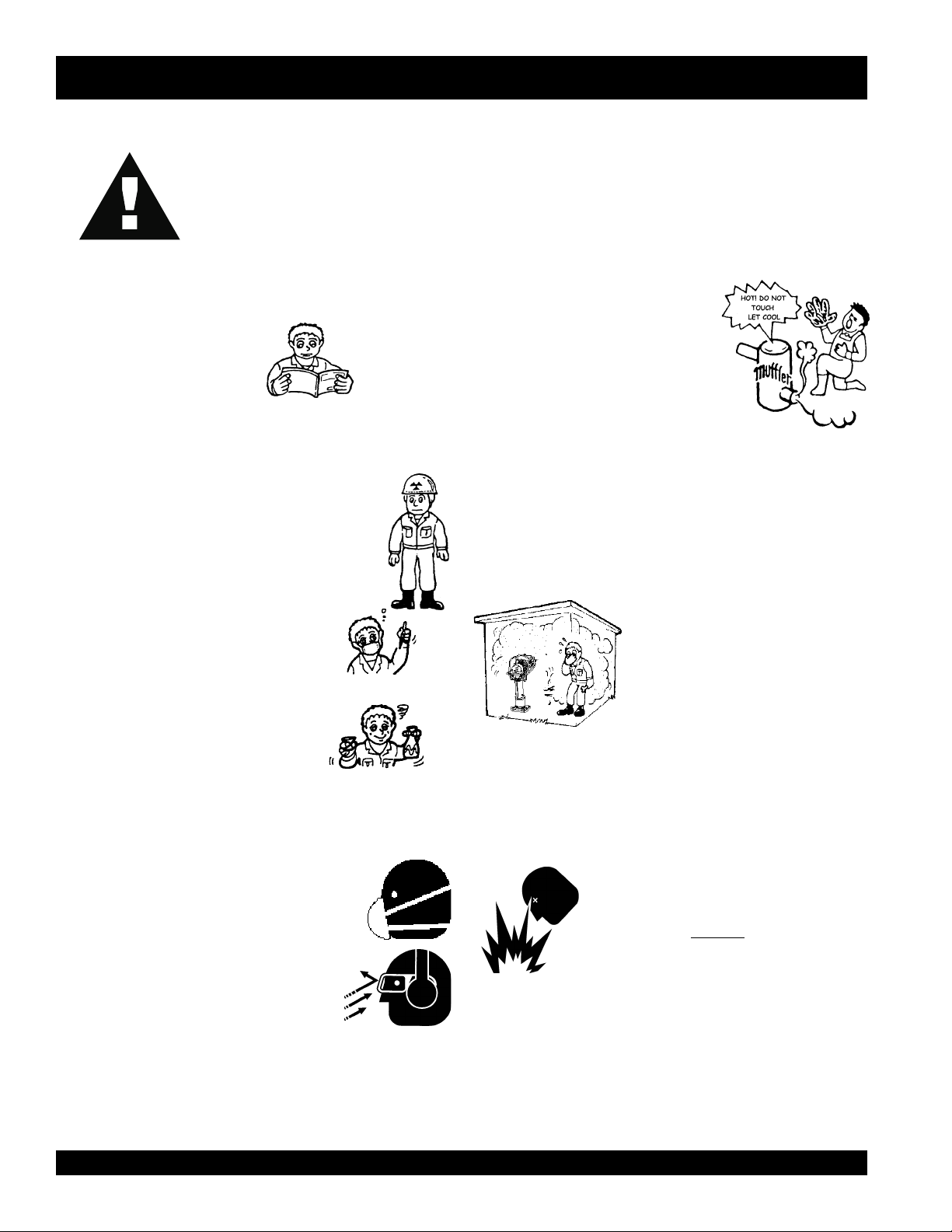
OPERATION AND SAFETY DECALS
PAGE 8 — MTR-80L — PARTS & OPERATION MANUAL — REV. #8 (06/26/01)
Page 9

Definition of Tamping Rammer
The Mikasa MTR-80L tamping rammer is a powerful compacting
tool capable of applying a tremendous force in consecutive
impacts to a soil surface. Its applications include soil compacting
for road, embankments and reservoirs as well as backfilling for
gas pipelines, water pipelines and cable installation work.
NOTE
Narrow extension shoe
accessories are available from
MQ.
The impact force of the MTR-80L levels and uniformly compacts
voids between soil particles to increase dry density.
Circular motion is converted to create impact force. The MTR60L tamping rammer develops a powerful compacting force at
the foot of the rammer. To maintain optimum performance, proper
operation and service are essential.
Construction of Tamping Rammer
GENERAL INFORMATION
The Mikasa MTR-80L Tamping Rammer is equipped with an
Robin air cooled, four cycle gasoline engine. Transmission of
the power takes place by increasing the engine speed to engage
the centrifugal clutch.
Rammer Gearbox and Spring Cylinder
The Mikasa MTR-80L uses an grease lubrication system. Always
apply grease to all grease fittings every 8 hours of operation.
(Shell Darina EP2 or Equivalent).
Controls
Before starting the MTR-80L Tamping Rammer, identify and
understand the function of the controls, see Figure 1 on page 11.
MTR-80L — PARTS & OPERATION MANUAL — REV. #8 (06/26/01) — PAGE 9
Page 10

LEDOM)cirtem(.S.UL08-RTM
thgieHllarevO)mm040,1(.ni5.04
htdiWllarevO)mm534(ni71
htgneLrevO)mm008(ni2/1-13
eziSeohS)mm543x003(.ni2/1.31x4/3-11
etunim/swolB056
aerAgnipmaTtf351,2-416,1
ecroFtcapmI)wolb/gk542,1(wolb/.sbl058,2
hctulClagufirtneCcitamotuA
thgieWgnitarepO)gk58(.sbl781
LEDOMENIGNEDTSG01-CENIBOR
epyTenignEenilosaGekortS2delooC-riA
MTR-80L — SPECIFICATIONS
snoitacificepSremmaRL08-RTM.1elbaTsnoitacificepSremmaRL08-RTM.1elbaT
snoitacificepSremmaRL08-RTM.1elbaTsnoitacificepSremmaRL08-RTM.1elbaT
snoitacificepSremmaRL08-RTM.1elbaT
2
2
m002-051(rh/
)rh/
snoitacificepSenignEDTSG01-CEniboR.2elbaTsnoitacificepSenignEDTSG01-CEniboR.2elbaT
snoitacificepSenignEDTSG01-CEniboR.2elbaTsnoitacificepSenignEDTSG01-CEniboR.2elbaT
snoitacificepSenignEDTSG01-CEniboR.2elbaT
ekortSXeroB )mm05X05(.ni23/13-1X23/13-1
tnemecalpsiDnotsiP)cc89(.ni.uc99.5
oitaRnoisserpmoC1:3.6
tuptuO.xaMmpr000,5/ph4
tuptuodetaRmpr000,4/ph3
euqroT.xaMmpr007,3)m-gk26.0(bl-tf74.4
noitpmusmoCleuF mpr000,4/sp3)h/PH/rg063(h/PH/bl497.0
roterubraC81VBCIM
yticapaCknaTleuF noitarepo.xorppasrh2)sretil5.1(.lag93.0
metsySnoitacirbuL metsySgniyarpSliOnoitacirbuL-leuF
leuF1liO:52
metsySnoitingIepyTotengaMleehwylF
metsySgninrevoGepyTthgiewylFlagufirtneC
gulPkrapSlauqEro4BKGN
metsySgnitratSretratSlioceR
thgieWyrD)gk2.31(sbl92
NOTE
Specifications are general and are subject to change without notice. If exact
measurements are required, equipment should be weighed and measured.
PAGE 10 — MTR-80L — PARTS & OPERATION MANUAL — REV. #8 (06/26/01)
Page 11
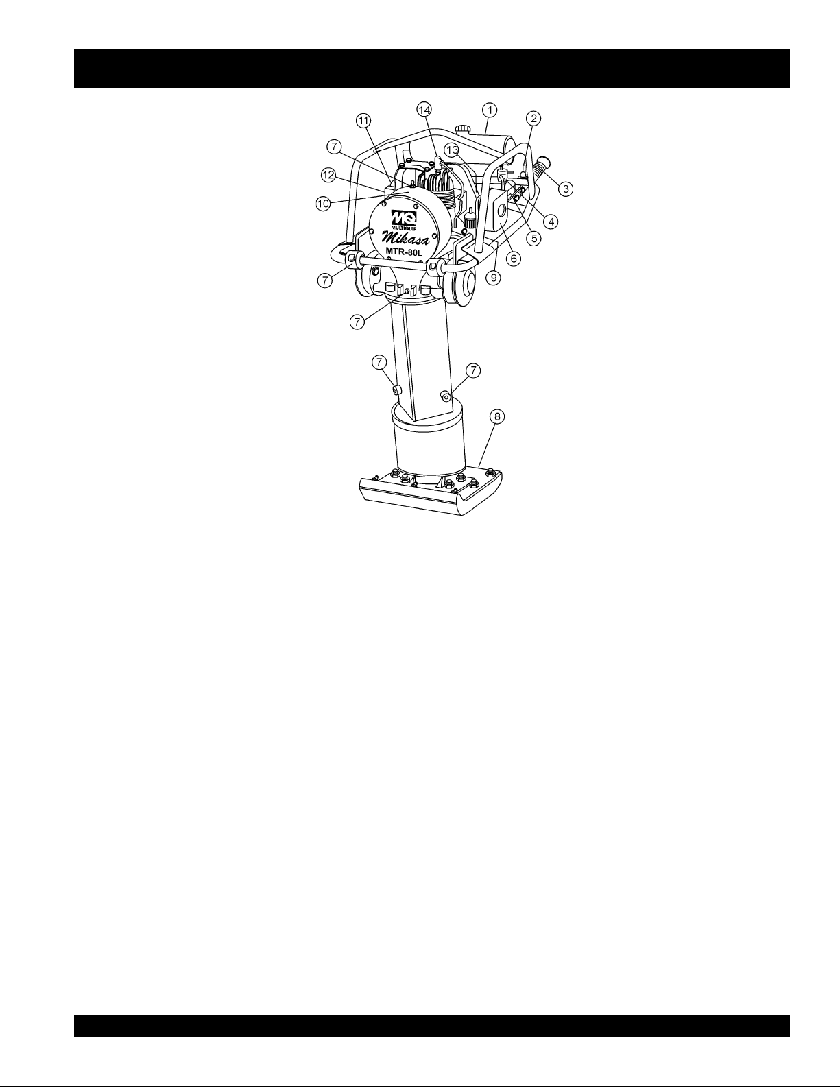
MTR-80L — CONTROLS AND COMPONENTS
Figure 1. MTR-80L Tamping Rammer
Figure 1 shows the location of the controls and components
for the MTR-80L Tamping Rammer. The functions of each
control is described below:
1. Fuel Tank/Cap – Remove this cap to add fuel. Tank holds
.39 gallons (1.5 liters ) unleaded. Mix 32:1 ratio with
outboard motor oil.
2. Throttle Lever – Controls engine speed and the tamping
action of the rammer.
3. Handle – To operate rammer
firmly.
4. Fuel Shut-Off Valve – Supplies fuel from the fuel tank to
the engine. To begin fuel flow move the fuel shut-off valve
downward.
5. Choke Lever – Used when starting the engine. Normally
used in cold weather conditions. In cold weather turn the
choke lever to the fully closed position, in warm weather
set choke lever half way or completely open.
6. Engine Air Cleaner – Prevents dirt and other debris
from entering the engine.
GRIP
handle assembly
8. Foot– Laminated wood with tempered steel plate for
superior shock absorption.
9. Fuel Valve – Open this valve to remove excess fuel from
the carburetor or crankcase.
10. Nameplate – Displays information regarding the rammer.
11. Muffler– Used to reduce noise and emissions.
12. Recoil Starting Handle – Used when starting the engine.
Pull starter handle sharply and quickly, then return
starter handle to starter case before releasing.
13. Engine Stop Switch – Controls the starting and stopping
of the engine. Switch must be in the "ON" position when
starting the engine.
14. Spark Plug – Provides spark to the ignition system,
replace with engine manufactures recommended type
spark plug.
7. Grease Fill Plugs – Grease these plugs to lubricate the
top and bottom mechanical component ends of the
rammer.
MTR-80L — PARTS & OPERATION MANUAL — REV. #8 (06/26/01) — PAGE 11
Page 12

MTR-80L OPERATION
1. Characteristics
The Mikasa rammer is a well- constructed, quiet, low
maintenance rammer designed to do the perfect confined area
compaction job.
types of soils and is used in all types of construction.
2. Construction
The rammer is powered by a two-cycle air cooled gasoline
engine.
engine speed through a centrifugal clutch to pinion gear.
rotary motion of the engine is converted to a vertical up and
down motion mechanism which is connected to a guided shoe.
3. Before Operation
3.1
two-wheel dolly cart.
does not fall over as damage may result.
3.2
operating.
GREASE GUN AS DAMAGE MAY RESULT.
lubrication points on the rammer.
head and three on the bottom part of the machine.
grease fitting five (5) shots of grease.
TEMPERATURE GREASE (PART #GRS2).
grease is used, the grease could become too thick or too thin
due to change in temperature and improper lubrication may
result.
GOVERNOR LUBRICATION.
the top of the engine crank case, and pour in the proper amount
of motor oil.
60cc (1-11/16 OZ.)
3.3
a well-blended mixture of 32 parts gasoline to one part motor
oil.
gasoline is not recommended.
two-cycle, or equivalent motor oil.
hours of initial use, a mixture of 20 parts gasoline to one part
motor oil must be used.
sure the filter (#112P19) is in place.
leak stopper (#159P19) is in the tank cap as the fuel will splash
out through the vent hole in the cap when the rammer is
operating.
3.4
cause screws and bolts to loosen, therefore periodically check
for tightness to avoid problems.
Power is transmitted from the engine by increasing the
If a cart is supplied, remove the tamping rammer from the
Grease the tamping rammer with a hand gun before
Fill the fuel tank with a fuel mixture of gasoline and oil.
A regular grade gasoline should be used.
Check all the screws and bolts for tightness. Vibration can
The MTR-80L is used primarily to compact all
The
Make sure the rammer stands steady and
CAUTION: DO NOT USE A POWER OPERATED
There are six (6)
Three are located on the rear
Give each
Be sure to use MQ HIGH
If an inferior type
Remove the oil plug, located on
(Summer: SAE #30; Winter: SAE #20).
Use any good quality outboard,
IMPORTANT: For the first 20
When filling the rammer with fuel, be
Also make sure that the
MTR-80L:
Use
High test ethyl
Brush away dust from the following places: the wire gauze
3.5
of the recoil starter; and guide spindle by removing the dust
protection sleeve; and from the foot.
lubrication and may cause excessive wear.
Adjust the height of the handle in accordance with the
3.6
operator.
by loosening the nuts.
4. Starting the Engine
4.1
Open the fuel cock assembly (#116AP19) on lower left side
of fuel tank by moving the lever downward.
Close the choke lever of the carburetor and move the throttle
4.2
lever of the handle to the “OFF” position.
starting, move the choke lever all the way up to the closed
position.
If you have difficulty in starting the engine, make sure the
open.
choke is in the half open position to prevent flooding the
carburetor with fuel.
Crank the engine by pulling the grip of the recoil starter
4.3
towards you and release.
4.4 When the engine starts, gradually move the choke lever
back to full open position.
Allow the engine to warm up for 3 to 5 minutes before
4.5
operating.
cover all engine parts.
If the engine will not start, remove and check the spark plug.
4.6
If the spark plug is wet or dirty, clean it or replace the spark plug.
After removing the spark plug, discharge any excess fuel by
cranking the engine two or three times by hand.
flooded, open the fuel discharge cock located at the lower of
part the crankcase and discharge the fuel by cranking the engine
two or three times.
the engine from running smoothly.
5. Operation
5.1 Move the throttle lever on the handle quickly from the “OFF”
to the “ON” position, and the tamping rammer starts operating.
CAUTION: Do not move the lever slowly as slow movement will
cause irregular operation and may damage the clutch, springs,
or foot.
After starting the rammer, adjust the tamping pressure in
5.2
accordance with the soil conditions by adjusting the throttle
As a general rule, fast tamping is used on soft ground and
lever.
slower tamping on hard ground.
designed to tamp the ground 600 to 650 times per minute with
an engine speed of 3,800-4,000 rpm.
most efficiently in this range.
revolutions will not always increase the tamping pressure.
Dust and dirt restrict proper
The side handle is designed to be adjusted with ease
For cold engine
When the engine is warm, the choke should be half
This allows the lubricating oil to fully circulate and
If the engine is
Too much fuel in the crankcase will prevent
The foot of the rammer is
The machine will work
An increase in the engine
PAGE 12 — MTR-80L — PARTS & OPERATION MANUAL — REV. #8 (06/26/01)
Page 13

MTR-80L OPERATION
5.3 In cold weather, the engine may operate sluggishly when
To warm up engine, the best way is to let engine idle for 5-
cold.
10 minutes with the of throttle lever at the “off position”.
The contact surface of the foot is covered with a heat treated
5.4
steel plate. When tamping, try to have the foot tamp the ground
evenly in order to prolong the life of the machine.
The machine is designed to advance or “walk” during
5.5
operation.
handle.
5.6 To stop the tamping rammer, move the throttle lever quickly
from “ON” to “OFF” position.
6. Stopping engine
6.1
To stop the engine, put the throttle lever to the “OFF” position
and allow the engine to run at low speed for three to five minutes.
After the temperature of the engine falls, push the stop button
until the engine stops completely.
it is still hot, the oil coating the cylinder bore may burn and
cause unnecessary wear.
Shut off the fuel supply by moving the lever on the fuel cock
6.2
assembly to the horizontal position.
should always be shut off when the rammer is not in use.
7. Service
7.1
dust, dirt, oil, etc. in the same manner mentioned in paragraph
7.2
element and wash in a solvent solution.
element in the sun and lubricate it with two-cycle engine fuel.
Shake off excess fuel and replace element.
plug; clean and adjust the spark gap to 0.7-0.8mm (0.027-0.031
in).
Check motor oil in the governor crankcase for prescribed
quantity, and add oil if supply is low.
months.
operate properly.
Monthly Services (200 hours):
7.3
and clean any dust or dirt that has accumulated in the fins of the
cylinder head.
the bore and exhaust manifold.
clean.
nuts.
To increase the travel speed, press down on the
Do not move the lever slowly.
If the engine is shut off while
NOTE: The fuel supply
Daily Service: Keep the machine clean by removing the
Weekly Services (50 Hours):
NOTE: Do not overfill as governor control will not
Remove the muffler and cylinder head, and clean
Clean the outside of the rammer. Retighten the bolts and
Replace oil in engine crankcase.
Remove the air cleaner
After cleaning, dry the
Remove the spark
Change oil every two
Remove the blower housing,
Remove the fuel filter cup and
8. Dismantling the tamping rammer
When dismantling the machine, be sure to disassemble in a clean,
dust-free area.
8.1
Removal of the Foot: Remove the dust sleeve strap. Then
loosen the four nuts on the foot plate and remove bolts.
can now be removed by lightly tapping it.
8.2
Removal of the Foot Plate: After removing the foot, remove
the lock washer by loosening bolt .
from the spindle rod .
8.3 Replacement of the Springs:
a. Loosen the four bolts which connect the guide cylinder and
crankcase.
b. Remove the cylinder pin by taking off the stop rings fitted to the
(bottom) cylinder cap, and the spring cylinder. Now the crankcase
can be completely separated.
c. Next, remove the four bolts which connect the double guide
and guide cylinder.
with the foot plate.
d. Remove the spring pin from the spring cylinder and remove the
cylinder cap (bottom) by loosening it gradually.
careful when removing bottom cylinder cap, as springs may spring
Spring replacement should be made in sets only.
out.
8.4
Replacement of the Crank Gear: Remove cylinder pin, guide
cylinder , crankcase, front cover, bolt , and lock washer, and
connecting rod.
the crank gear from engine side, and remove.
Replacement of the Clutch: The clutch assembly can be
8.5
taken off by loosening the nut on the engine crankshaft.
removing the clutch shoe, take off the washer to prevent turning
front
the
the clutch shoes as one complete set.
8.6 Replacement of Pinion Gear: Remove engine. Tap on the
head of pinion using a hammer to pull out the pinion.
bolt and lock washer. After that disassemble them from the bolt
side in order.
The foot
Then remove the foot plate
Separate them, and locate the cylinder pin.
The complete spring cylinder can be removed
CAUTION: Be
After removing bearing cover and stop ring, hit
When
clutch guide, clutch guide , and clutch spring .
Replace
Remove the
7.4
Storage: In case of long storage after using the rammer,
drain all the fuel tank, fuel pipe and carburetor.
spark plug and pour several drops of oil into the cylinder bore.
Clean the outer surface of the machine and coat the surface
with a light coat of oil.
dry place.
Cover the machine and store in a clean,
MTR-80L — PARTS & OPERATION MANUAL — REV. #8 (06/26/01) — PAGE 13
Remove the
Page 14
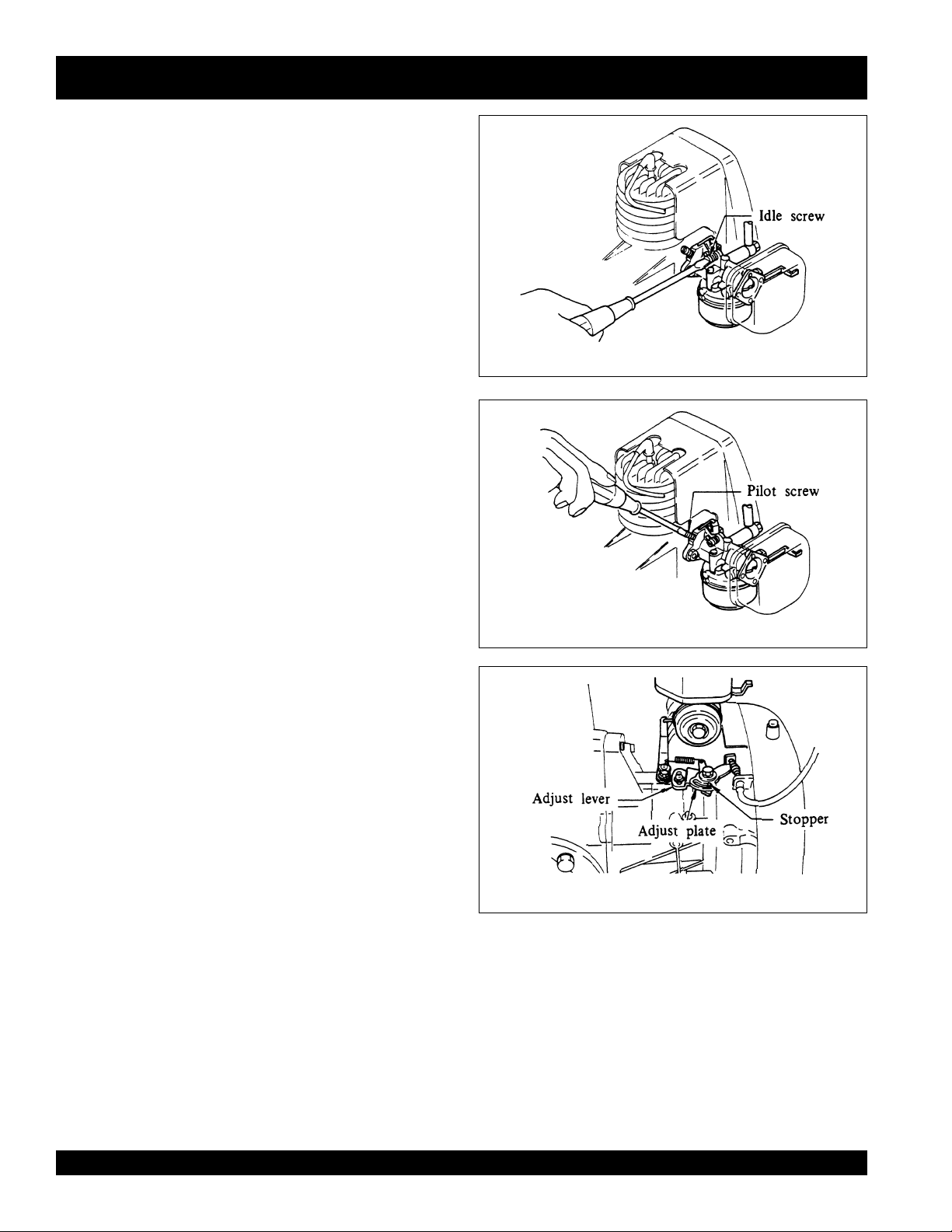
9.1 Idle Adjustment
9.1-1
Adjust idle when engine is warm.
9.1-2
With the throttle in a “off” position, adjust idle screw
(Fig. 1) to approximately 1,200±100.
9.2 Pilot Adjustment
9.2-1
Turn pilot screw (Fig. 2) to closed position. Open
approximately one full turn for smooth engine idling.
9.3 High speed Adjustment
9.3-1
Loosen adjust plate screw and adjusting lever bolt
(Fig. 3).
For slower speed, move stopper (Fig. 3) toward the recoil
9.3-2
starter.
9.3-3
recoil starter.
9.3-4
100rpm.
This shortens the throttle movement.
To increase speed, move stopper (Fig. 3) away from
This increases the throttle movement.
Set engine at correct speed of approximately 3,900±
Tighten adjust plate screw and adjusting lever bolt.
MTR-80L OPERATION
Fig. 1
Fig. 2
Fig. 3
PAGE 14 — MTR-80L — PARTS & OPERATION MANUAL — REV. #8 (06/26/01)
Page 15

MTR-80L — TROUBLESHOOTING GUIDE
GNITOOHSELBUORTENIGNE.4ELBAT
MOTPMYS MELBORPELBISSOP NOITULOS
tratsottluciffiD
?egdirbgniebgulpnoitingI .metsysnoitingikcehC
.)elbacnoisnethgihta
rewoP(.etingitonlliw TON
noisserpmoc(setingi )lamron .
noisserpmoc(setingi wol .)
yrotcafsitastonnoitarepO
gulpkrapstubelbaliavasileuF
elbaliavarewoP(.etingitonlliw
?srotalusni
gulpkrapstubelbaliavasileuF
.)elbacnoisnethgihtaelbaliava
?stisoped
gulpkrapsdnaelbaliavasileuF
gulpkrapsdnaelbaliavasileuF
?etauqedani
?)tsud
?nrowrednilyC .rednilycecalpeR
?esoolgulpkrapS .gulpkrapsnehgiT
?noitingitatisopednobraC .noitingiecalperronaelC
evitcefedoteudtiucrictrohS
?pagkrapsreporpmI .pagtcerrocehtotpaggulpkrapsteS
?hctiwspotstatiucrictrohS .evitcefedfihctiwspotsecalpeR.tiucrichctiwspotskcehC
?evitcefedliocnoitingI .liocnoitingiecalpeR
nobrachtiwdeggolcrelffuM
siytilauqleufdexiM
,retaw(etauqedaniesunileuF
?deggolcrenaelCriA .renaelcriaecalperronaelC
?teksagdaehrednilycevitcefeD .teksagdaehecalperrostlobdaehrednilycnethgiT
.srotalusniecalpeR
.relffumecalperronaelC
.erutximliootleufkcehC
.leufhserfhtiwecalperdnametysleufhsulF
?deggolcrenaelcriA
elbaliavarewophguonetoN
-ssimon,lamronnoisserpmoc(
.)gnirif
elbaliavarewophguonetoN
-ssim,lamronnoisserpmoc(
.)gnirif
?)tsud
.staehrevoenignE
?enilleufniriA .enilleufmorf)riaevomer(deelB
?reporpmirebmahc
?evitcefedliocnoitingI .leufhserfhtiwecalperdnametysleufhsulF
siytilauqleufdexiM
?etauqedani
?rebmahcnoitsubmoc
.nobrac
taolfrotaerubracnilevelleuF
?rednilycnistisopednobraC rednilycecalperronaelC
?strohsnetfogulpnoitingI .noitinginaelc,seriwnoitingiecalpeR
,retaw(etauqedaniesunileuF
ninoitsopednobracevissecxE
htiwdeggolcrelffumrotsuahxE
?tcerrocnieulavtaehgulpkrapS .gulpkrapsepyttcerrochtiwgulpkrapsecalpeR
taolfrotaerubractsujdA
.leufhserfhtiwecalperdnametysleufhsulF
.erutximliootleufkcehC
.esacknarcecalperronaelC
.relffumecalperronaelC
MTR-80L — PARTS & OPERATION MANUAL — REV. #8 (06/26/01) — PAGE 15
Page 16

MTR-80L — TROUBLESHOOTING GUIDE
ENGINEENGINE
ENGINE
ENGINEENGINE
MOTPMYS MELBORPELBISSOP NOITULOS
yrotcafsitastonnoitarepO
?reporpmitnemtsujdaronrevoG .reveltcerrocotronrevogtsujdA
?evitcefedgnirpsronrevoG .noitingiecalperronaelC
.setautculfdeepslanoitatoR
?citarrewolfleuF .enilleufkcehC
)deunitnoc(GNITOOHSELBUORTENIGNE.4ELBAT
noitcushguorhtninekatriA
?enil
gnikrowtonretratslioceR
.ylreporp
MOTPMYS MELBORPELBISSOP NOITULOS
ediutilpmatubsetatorenignE
.ekirtstonseodromrofinuton
?spilshctulC .hctulctsujdaroecalpeR
?trapgnitatornitsuD .ylbmessaretratsliocernaelC
?eruliafgnirpsgnirpS .gnirpslairpsecalpeR
revelelttorhtfodeepsgnitarepO
?tesyltcerrocnisi
?ssecxeniliO .leveltcerrocotgnirB.liossecxeniarD
?eruliaFgnirpS .gnirpslairpsecalpeR
.enilnoitcuskcehC
GNITOOHSELBUORTREMMAR.5ELBAT
.noitisoptcerrocotrevelelttorhtteS
?reporpmienignefodeepS .gnittesMPRgnitarepotcerrocotdeepsenignetsujdA
PAGE 16 — MTR-80L — PARTS & OPERATION MANUAL — REV. #8 (06/26/01)
Page 17

NOTE PAGE
MTR-80L — PARTS & OPERATION MANUAL — REV. #8 (06/26/01) — PAGE 17
Page 18

EXPLANATION OF CODE IN REMARKS COLUMN
How to read the marks and remarks used in this parts
book.
Items Found In the “Remarks” Column
Serial Numbers-Where indicated, this indicates a serial
number range (inclusive) where a particular part is used.
Model Number-Where indicated, this shows that the
corresponding part is utilized only with this specific model
number or model number variant.
Items Found In the “Items Number” Column
All parts with same symbol in the number column,
■
, belong to the same assembly or kit.
If more than one of the same reference number is
listed, the last one listed indicates newest (or latest)
part avaliable.
, #, +, %, or
*
NOTE
NOTE
The contents of this catalog are
subject to change without notice
PAGE 18 — MTR-80L — PARTS & OPERATION MANUAL — REV. #8 (06/26/01)
.
Page 19

MTR-80L SUGGESTED SPARE PARTS
MTR-80L Mikasa Rammer
1 to 3 Units
Qty. PIN Description
10 ....... GRS2.................. Grease, high temp.
3 ......... 0650140010 ....... Spark plug
1 ......... 956300060 ......... Lever, throttle assy.
1 ......... 501302060 ......... Wire, throttle
1 ......... 0643000101 ....... Drain Cock
2 ......... 505015060 ......... Nipple, A-grease
2 ......... 505015070 ......... Nipple, B-grease
1 ......... 301910081 ......... Tank cap assy.
1 ......... 954300390 ......... Fuel cock
3 ......... 301419750 ......... Filter, in-line fuel
1 ......... 959401750 ......... Stopper for wire
1 ......... 402010110 ......... Spring, return throttle
3 ......... 1063270407 ....... Element, air cleaner
1 ......... 0669900207 ....... Button, stop (S/N C1092 & Below)
1 ......... 0660000370 ....... Switch, stop (S/N C1093 & Above)
MTR-80L Mikasa Rammer
3 to 5 Units
Qty. PIN Description
10 ....... GRS2.................. Grease, high temp.
3 ........ 0650140010 ....... Spark plug
2 ........ 956300060 ......... Lever, throttle assy.
2 ........ 501302060 ......... Wire, throttle
1 ........ 0643000101 ....... Drain Cock
2 ........ 505015060 ......... Nipple, A-grease
2 ........ 505015070 ......... Nipple, B-grease
1 ........ 301910081 ......... Tank cap assy.
2 ........ 954300390 ......... Fuel Cock
5 ........ 301419750 ......... Filter, in-line fuel
2 ........ 959401750 ......... Stopper for wire
2 ........ 402010110 ......... Spring, return throttle
4 ........ 1063270407 ....... Element, air cleaner
1 ........ 0669900207 ....... Button, stop (S/N C1092 & Below)
1 ........ 1066230207 ....... Kit, carburetor
1 ........ 0660000370 ....... Switch, stop (S/N C1093 & Above)
MTR-80L Mikasa Rammer
5 to 10 Units
Qty. PIN Description
10 ....... GRS2.................. Grease, high temp.
10 ....... 0650140010 ....... Spark plug
1 ......... 0655000051 ....... Cap, spark plug
3 ......... 956300060 ......... Lever, throttle assy.
3 ......... 501302060 ......... Wire, throttle
2 ......... 0643000101 ....... Drain cock
4 ......... 505015060 ......... Nipple, A-grease
4 ......... 505015070 ......... Nipple, B-grease
2 ......... 301910081 ......... Tank cap assy.
2 ......... 954300390 ......... Fuel cock
10 ....... 301419750 ......... Filter, in-line fuel
3 ......... 959401750 ......... Stopper for wire
3 ......... 402010110 ......... Spring, return throttle
2 ......... 1069900107 ....... Gasket set
2 ......... 1062350107 ....... Ring set, standard
10 ....... 1063270407 ....... Element, air cleaner
3 ......... 0669900207 ....... Button, stop (S/N C1092 & Below)
2 ......... 1066230207 ....... Kit, carburetor
3 ......... 0660000370 ....... Switch, stop (S/N C1093 & Above)
3 ......... 0642001410 ....... Bowl, fuel cock
3 ......... 954405080 ......... Fuel filter, tank cap
MTR-80L Mikasa Rammer
10+ Units
Qty. PIN Description
20 ....... GRS2.................. Grease, high temp.
14 ....... 0650140010 ....... Spark plug
2 ......... 0655000051 ....... Cap, spark plug
4 ......... 956300060 ......... Lever, throttle assy.
4 ......... 501302060 ......... Wire, throttle
5 ......... 0643000101 ....... Drain cock
6 ......... 505015060 ......... Nipple, A-grease
6 ......... 505015070 ......... Nipple, B-grease
3 ......... 301910081 ......... Tank cap assy.
3 ......... 954300390 ......... Fuel cock
12 ....... 301419750 ......... Filter, in-line fuel
4 ......... 959401750 ......... Stopper for wire
4 ......... 402010110 ......... Spring, return throttle
3 ......... 1069900107 ....... Gasket set
3 ......... 1062350107 ....... Ring set, standard
12 ....... 1063270407 ....... Element, air cleaner
4 ......... 0669900207 ....... Button, stop (S/N C1092 & Below)
4 ......... 1066230207 ....... Kit, carburetor
1 ......... 1066251600 ....... Carburetor
4 ......... 0642001410 ....... Bowl, fuel cock
4 ......... 954405080 ......... Fuel filter, tank cap
1 ......... 1065081310 ....... Recoil starter assembly
3 ......... 0660000370 ....... Switch, stop (S/N C1093 & Above)
1 ......... 301421360 ......... Clutch assembly
1 ......... 1063272800 ....... Air cleaner assembly
MTR-80L — PARTS & OPERATION MANUAL — REV. #8 (06/26/01) — PAGE 19
Page 20

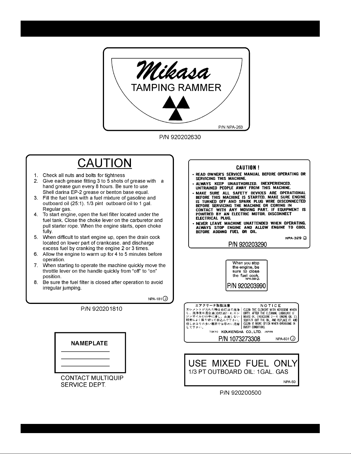
MTR-80L— NAME PLATE AND DECALS
PAGE 20 — MTR-80L — PARTS & OPERATION MANUAL — REV. #8 (06/26/01)
Page 21

MTR-80L— NAMEPLATE AND DECALS
NAME PLATE AND DECALS
NO PART NO PART NAME QTY. REMARKS
1
*
2
*
3
*
5
*
6 PLATE, SERIAL NO. 1 CONTACT MQ SERVICE DEPT. W/MODEL & S/N
7
*
10 DCLMTR-80L KIT, DECAL ................................................... 1 ............ INCLUDES ITEMS W/
SEE DECAL ILLUSTRATIONS ON PAGE 8.
920200500 DECAL: MIXED FUEL 1 NPA-50
920203290 DECAL: CAUTION READ 1 NPA-329
920201810 DECAL: CAUTION 1 NPA-181
920203990 DECAL: FUEL SHUT-OFF 1 NPA-399
920202630 DECAL: MIKASA LOGO 1 NAP-263
*
MTR-80L — PARTS & OPERATION MANUAL — REV. #8 (06/26/01) — PAGE 21
Page 22

CRANKCASE AND ENGINE ASSY.
MTR-80L — CRANKCASE AND ENGINE ASSY.
PAGE 22 — MTR-80L — PARTS & OPERATION MANUAL — REV. #8 (06/26/01)
Page 23

MTR-80L — CRANKCASE AND ENGINE ASSY.
CRANKCASE AND ENGINE ASSY.
NO. PART NO. PART NAME QTY. REMARKS
1 2008020 BOLT 8X16 ........................................... 6 ............REPLACES 001200816 AND 0017108016
2 030208200 WASHER SW M8 10
2 030208200 WASHER SW M8 .................................6 ............ QC
3 301205230 FRONT COVER MTR-80L 1
3 301300060 FRONT COVER MTR-80G 1
5 011008020 BOLT 8X20 H ....................................... 2 ............REPLACES 001210820
6 301010050 LOCK WASHER, 8X32 ........................1 ............ BELOW S/N C9661
6 952400690 WASHER 9X35X4.5 ............................. 1 ............S/N C9661 AND ABOVE
6 030208200 WASHER LOCK 8MM ..........................1 ............ S/N C9661 AND ABOVE
7 080100620 STOP RING R-62 1
8 042006305 BEARING 6305ZZ 2
9 301300530 CONNECTING ROD 1
10 301300120 CRANK GEAR...................................... 1 ............BELOW S/N C9661
10 301300126 CRANK GEAR ...................................... 1 ............ S/N C9661 AND ABOVE
11 041006307 BEARING 6307Z 1
12 080200350 STOP RING S-35 2
13 301010071 CRANK CASE MTR-80L 1
13 301010080 CRANK CASE MTR-80G 1
14 505015060 GREASE FITTING A MTR-80L 3
14 505015070 GREASE FITTING B MTR-80-G 1
15 920100200 PLATE, GREASE MARK ......................3 ............ IN KIT DCL 80L
18 301010110 PACKING, BEARING HOLDER ........... 1 ............DC
19 301010120 BEARING HOLDER ............................. 1 ............DC
21 301010130 PACKING, BEARING COVER 1
22 080200250 STOP RING S-25 1
23 001200616 BOLT 6X16 4
23 011706020 BOLT 6X20 H, SW ...............................4 ............ REPLACES 002210620
24 030206150 WASHER SW M6 .................................4 ............ DC
25 301441360 BEARING COVER ................................ 1 ............REPLACES 301010140
26 2008020 BOLT 8X16 ........................................... 4 ............DC REPLACES 001200816 AND 0017108016
28 030210250 WASHER SW M10 3
29 001211040 BOLT 10X40 H .....................................3 ............DC
29-1 0105051045 BOLT 10X45 H ..................................... 2 ............OX
29-2 012210035 BOLT 10X35 H .....................................1 ............OX
32 951010060 KEY 5X5X32 1
33 301010160 PINION 1
34 042006205 BEARING 6205ZZ 1
36 042006207 BEARING 6207ZZ 1
37 301441350 SPACER, CLUTCH DRUM .................. 1 ............REPLACES 301010170 & 301321460
38 301010180 FELT RING 1
39 352437870 CLUTCH DRUM................................... 1 ............REPLACES 301010190
40 301010200 LOCK WASHER 8X25 1
46
47
48
49
50
51
54 0053204201 WOODRUFF KEY ............................... 1 ............REPLACES 951403420
55 301420750 SPACER 15X21X4T, CLUTCH ............ 1 ............DC BELOW S/N V4260
155 911101005 ENGINE ASSY. EC10G ........................1 ............ REPLACES 911101008
156 301421360 CLUTCH ASSY./C812A ....................... 1 ............INCLUDES ITEMS W/
157 PLATE, SERIAL NO. ............................1 ............ CONTACT MQ SERVICE DEPT. W/MODEL & S/N
301010210 LOCK WASHER, CLUTCH 1
*
943060020 CLUTCH GUIDE/B 1
*
943030020 CLUTCH SPRING 2
*
943020020 CLUTCH SHOE 4
*
943050050 CLUTCH BOSS 1
*
943060010 CLUTCH GUIDE/A 1
*
*
MTR-80L — PARTS & OPERATION MANUAL — REV. #8 (06/26/01) — PAGE 23
Page 24

CYLINDER GUIDE AND FOOT ASSY.
MTR-80L — CYLINDER GUIDE AND FOOT ASSY.
EXCLUDES 102
PAGE 24 — MTR-80L — PARTS & OPERATION MANUAL — REV. #8 (06/26/01)
Page 25

MTR-80L — CYLINDER GUIDE AND FOOT ASSY.
CYLINDER GUIDE AND FOOT ASSY.
NO. PART NO. PART NAME QTY. REMARKS
57# 301010310 PROTECTOR RUBBER 1
58# 301300520 SPINDLE ROD 1
60 301010340 CYLINDER PIN 1
61 080100150 STOP RING R-15 ................................2 ............ REPLACES 301010350
63# 025404010 SPRING PIN 4X10W............................ 4 ............ DC
67 301010380 PACKING, GUIDE CYL. (TOP) 1
68 301100422 GUIDE CYLINDER............................... 1 ............REPLACES 301100420
69
70 001211032 BOLT 10X32 H 4
70 012210035 BOLT 10X35 H .....................................4 ............XO REPLACES 001211035
71 020310080 NUT M10 4
72 001211032 BOLT 10X32 H 4
72 001211040 BOLT 10X40 H .....................................4 ............OX
73 301010410 PACKING, GUIDE CYL. (BOTTOM) 1
74 920100200 PLATE, GREASE MARK 3
75 505015060 GREASE FITTING A/MQ 3
76 301010420 EYE BOLT M12X20 ............................. 1 ............DC
77 301304990 DUST SLEEVE 1
78 301010450 STRAP.................................................. 1 ............ REQUIRES 79,80, AND NUT P/N 020108060
79 011208030 BOLT 8X25 T ........................................ 1 ............ REPLACES 001400830
80 030208200 WASHER SW M8 1
88 301010460 RUBBER SPACER 2
89 065101030 DUST SEAL DKI-183069 2
90 080100300 STOP RING R-30 2
91 301010480 GUIDE SPINDLE 2
92 301010490 FOOT PLATE 1
93 025306032 SPRING PIN 6X32 ...............................2 ............ REPLACES 025406032
94 301400080 LOCK WASHER 1
96% 021110120 NYLON NUT M10 ................................8 ............ REPLACES 022711012
98
99
100$ 021112140 NYLON NUT M12 ................................4 ............REPLACES 022711214
101 030212300 WASHER SW M12 4
102 015112060 SUNK HEAD BOLT 12X70 H ............... 4 ............ INCL'S ITEM W/$ REPL. 001611254 & 015112075
105
106
107
107 FOOT 14" ............................................. 1 ............OPTION SOLD THROUGH UNIT SALES DEPT.
108
108 METAL SHEET 14" ..............................................NO LONGER AVAILABLE SEPARATELY
140 301910030 FOOT ASSY. 300W-6T 11-3/4" W/HOLE ............1 INCLUDES ITEMS W/
145# 301300150 CYLINDER CAP (BOTTOM) 1
146# 301300136 CYLINDER CAP (TOP) ........................ 1 ............ REPLACES 301300130
147# 301300140 SPRING CYLINDER 1
148# 301300110 MAIN SPRING (A,B,C) 2
149 301910050 SPRING CYLINDER ASSY. ................. 1 ............ INCLUDES ITEMS W/#
150 001121440 BOLT 14X40 T,P1.5 1
151 301106210 DOUBLE GUIDE CP (W/BUSH) .......... 1 ............ INCLUDES ITEMS W/+
152 065103020 DUST SEAL DKI-3446710 1
154+ 080100470 STOP RING R-47 ................................2 ............ REPLACES 080510470
160+ 301406100 SLEEVE DOUBLE GUIDE 2
161+ 301424060 BUSHING (B) DOUBLE GUIDE 1
030210250 WASHER SW M10 16
*
506404060 WASHER 11X34X3.2 ........................... 2 ............REPLACES 301010540
*
015110055 SUNK HEAD BOLT 10X55 H ............... 5 ............INCL'S ITEM W/% REPLACES 001611051
*
301010550 FOOT FITTING 2
*
015110055 SUNK HEAD BOLT 10X55 H ............... 3 ............INCL'S ITEM W/% REPLACES 001611051
*
301010560 FOOT 11-3/4 (W) X 14 (L) STD. 1
*
REPLACES 301010990
301010570 METAL SHT. 11-3/4 (W) X 14 (L) STD. 1
*
*
MTR-80L — PARTS & OPERATION MANUAL — REV. #8 (06/26/01) — PAGE 25
Page 26

TANK AND HANDLE ASSY.
MTR-80L — TANK AND HANDLE ASSY.
116-1
116-2
116-3
PAGE 26 — MTR-80L — PARTS & OPERATION MANUAL — REV. #8 (06/26/01)
Page 27

MTR-80L — TANK AND HANDLE ASSY.
TANK AND HANDLE ASSY.
NO. PART NO. PART NAME QTY. REMARKS
109A 301910081 TANK CAP ASSY ................................. 1 ............INCLUDES ITEMS W/
109*953404280 TANK CAP ............................................ 1 ............ 00 REPLACES 301010740
110
112 954405080 FUEL FILTER ....................................... 1 ............REPLACES 301010760
113 301010780 FUEL TANK 1
114 030208200 WASHER SW M8 6
115 001200815 BOLT 8X15 6
116 954300390 FUEL COCK ASSY .............................. 1 ............INCLUDES ITEMS W/# REPLACES 301322990
116-1# 0642001410 CUP, FUEL COCK 1
116-2# 0642001420 SCREEN, FUEL COCK 1
116-3# 0642001430 RUBBER PACKING, FUEL COCK 1
118+ 301420540 PROTECT SPRING 10X180 1
120 001201081 BOLT 10X58 6
121% 301105270 HANDLE 80L 1
122 001201050 BOLT 10X50 6
123 030210250 WASHER SW M10 14
124 301010810 RUBBER COUPLING 2
126 020310080 NUT M10 8
127 959401750 WIRE STOPPER, ASSY. 1
128 402010110 RETURN SPRING ...............................1 ............REPLACES 301010950
129 301010900 THROTTLE WIRE-80G 1
129 501302060 THROTTLE WIRE-80L........................ 1 ............REPLACES 301312630
130 956300060 THROTTLE LEVER ASSY. 1
131 301010830 RUBBER GRIP 1
132 301010840 SIDE HANDLE 1
135 001211030 BOLT 10X30 H 2
136 031110160 WASHER PW M10 2
142
143
144
158
159
160+ 301420730 HOSE CLAMP 11 ................................. 2 ............ REPLACES 303010490
160+ 301420730 HOSE BAND (8) 4
161+ 301420330 FUEL HOSE R-170 (8”)1
161+ 302420320 FUEL HOSE (3”) ..................................1 ............REPLACES 301419760
162+ 301419750 FUEL FILTER 1
163+ 302420320 FUEL HOSE 1
164 301910090 FUEL HOSE ASSY .............................. 1 ............INCLUDES ITEMS W/+
165+ 301420730 HOSE CLAMP 2
166 301910100 HANDLE ASSY. 80L W/ROLLER ......... 1 ............ INCLUDES ITEMS W/%
167% 301421840 ROLLER 4
168% 001200525 BOLT 5X25 4
169% 031105080 WASHER PW M5 8
170% 020305040 NUT 4
171 959403750 RUBBER SLIP STOP 1
172 2267510103 CLAMP 1
■
301420050 PLATE 1
*
■
920202630 DECAL, TRADE MARK/RAMMER ....... 1 ............REPLACES 920100340
■
920201810 DECAL, CAUTION 1
■
920200500 DECAL, MIXED FUEL 1
301010850 SPONGE 1
*
301010860 LEAK STOPPER 1
*
DCL80 DECAL KIT 1 INCLUDES ITEMS W/■ AND P/N 920100980 E/G
RPM IN CRANKCASE AND ENGINE ITEM 15
*
MTR-80L — PARTS & OPERATION MANUAL — REV. #8 (06/26/01) — PAGE 27
Page 28

ROBIN EC-10G ENGINE — CRANKCASE AND CYLINDER ASSY.
CRANKCASE AND CYLINDER ASSY.
PAGE 28 — MTR-80L — PARTS & OPERATION MANUAL — REV. #8 (06/26/01)
Page 29

ROBIN EC-10G ENGINE — CRANKCASE AND CYLINDER ASSY.
CRANKCASE AND CYLINDER ASSY.
NO. PART NO. PART NAME QTY. REMARKS
1 1061030501 CRANKCASE ASSY............................. 1 ............INCLUDES ITEMS W/#, REPLACES
1061030211 & 1061030131
5# 0440200010 OIL SEAL TB20328 3
6 0670070100 AIR BREATHER 1
7# 0600200020 BEARING 6204 C3 2
8# 0105070010 STUD 4
10 1066360601 OIL GAUGE CP. ................................... 1 ............ INCLUDES ITEMS W/+
11+ 0210160010 GASKET 1
21# 0440080010 OIL SEAL VC8144 1
23 0031008000 WASHER 2
24 030208200 SPRING WASHER 8MM ......................4 ............ REPLACES 0032008000
28 020108060 NUT 8MM ............................................. 2 ............REPLACES 0021908000
29 0013106301 STUD BOLT 2
30% 1063510201 GASKET CP. EXHAUST 1
31 1061240901 CYLINDER CP. ..................................... 1 ............ INCLUDES ITEMS W/%, REPLACES 1061240511
32 0013108301 STUD BOLT 2
33% 1063500103 GASKET 2
34 1063290203 INSULATOR 1
35 0031006000 WASHER 2
36 030206150 SPRING WASHER 6MM ......................6 ............ REPLACES 0032006000
37 020106050 NUT 6MM ............................................. 2 ............REPLACES 0022706000
38 0655000051 SPARK PLUG CAP .............................. 1 ............ REPLACES 0655000050
39 0650140010 SPARK PLUG NGK B-4 1
43# 0011406350 BOLT AND WASHER ASSY. 4
45 0170070020 NUT 4
46
48 0016606120 BOLT 4
49 0241070090 GROMMET 1
52 020106050 NUT 6MM ............................................. 1 ............REPLACES 0022706000
53 0149060040 ADJUSTING SCREW 1
55 1061300113 CYLINDER HEAD 1
56
58 0643000101 DRAIN COCK ....................................... 1 ............REPLACES 0643000100
60 0103080010 BOLT HEAD 2
66 0205060010 LOCK WASHER 4
67 1061160111 CRANK CASE COVER 1
68
69 0011406160 BOLT AND WASHER ASSY. 4
70 0302088200 SPRING WASHER 4
71 0401080020 PLUG.................................................... 1 ............REPLACES 0401080010
72 0210080010 GASKET DRAIN 1
74L 0130080071 BOLT AND WASHER ASSY. 2
*
73 0440200010 OIL SEAL 3
1061500123 GASKET CYLINDER 1
*
1061510111 GASKET CP HEAD 1
*
1061500203 GASKET CASE COVER 1
*
1069900107 GASKET SET ....................................... 1 ............ INCLUDES ITEMS W/
*
MTR-80L — PARTS & OPERATION MANUAL — REV. #8 (06/26/01) — PAGE 29
Page 30

ROBIN EC-10G ENGINE — CRANKSHAFT AND PISTON ASSY.
CRANKSHAFT AND PISTON ASSY.
PAGE 30 — MTR-80L — PARTS & OPERATION MANUAL — REV. #8 (06/26/01)
Page 31

ROBIN EC-10G ENGINE — CRANKSHAFT AND PISTON ASSY.
CRANKSHAFT AND PISTON ASSY.
NO. PART NO. PART NAME QTY. REMARKS
1 1062020210 CRANKSHAFT ASSY. .......................... 1 ............INCLUDES 2,4-6
7 0610120010 NEEDLE BEARING 1
9 1062340111 PISTON COMPL, STD ......................... 1 ............ INCLS. 8
9 1062340211 PISTON COMPL, 0.25 MM O/S ........... 1 ............ INCLS. 8, REPLACES 1062340201
9 1062340311 PISTON COMPL, 0.50 MM O/S ........... 1 ............ INCLS. 8, REPLACES 1062340301
10 1062350107 PISTON RING SET, STD 1
10 1062350207 PISTON RING SET, 0.25 MM O/S 1
10 1062350307 PISTON RING SET, 0.50 MM O/S 1
11 1062330113 PISTON PIN 1
12 0565120010 CLIP 2
14 1064190303 GOVERNOR SLEEVE 1
15 1064170201 GOVERNOR PLATE COMPL. 1
16 0565200020 CLIP 2
19 0173120010 LOCK NUT 1
20 0053204201 WOODRUFF KEY ............................... 1 ............REPLACES 0323040010
21 0053204201 WOODRUFF KEY 1
22 0053204201 WOODRUFF KEY 1
23 0170100010 NUT 1
24 030210250 SPLIT WASHER 10MM ........................ 1 ............ REPLACES 0032010000
MTR-80L — PARTS & OPERATION MANUAL — REV. #8 (06/26/01) — PAGE 31
Page 32

GOVERNOR ASSY.
ROBIN EC-10G ENGINE — GOVERNOR ASSY.
PAGE 32 — MTR-80L — PARTS & OPERATION MANUAL — REV. #8 (06/26/01)
Page 33

ROBIN EC-10G ENGINE — GOVERNOR ASSY.
GOVERNOR ASSY.
NO. PART NO. PART NAME QTY. REMARKS
1 1064220103 GOVERNOR SHAFT 1
2 1064210113 GOVERNOR YOKE 1
3 0032004000 WASHER, SPRING 3
4 0043504060 SCREW ................................................2 ............REPLACES 0043104060
5 020106050 NUT ......................................................1 ............REPLACES 0022706000
6 030206150 SPRING WASHER 6MM ...................... 1 ............ REPLACES 0032006000
7 1064240101 ADJUSTING PLATE 1
8 1064280113 ROD SPRING ......................................1 ............REPLACES 1064280111
9 1054270111 GOVERNOR ROD 1
10 1064230111 GOVERNOR LEVER ...........................1 ............REPLACES 1064230101
11 1054250103 GOVERNOR SPRING .........................1 ............REPLACES 1054250101
12 1064330620 GOVERNOR CONTROL ..................... 1 ............REPLACES 1054330109
14 0043108160 SCREW ................................................1 ............REPLACES 0011708160
22 0043504080 SCREW AND WASHER ASSY. ............ 1 ............ REPLACES 0043604080
23 402010110 COIL SPRING ...................................... 1 ............REPLACES 0830000010
24 1064350400 STOP PLATE ....................................... 1 ............REPLACES 1054350121
25 0031004000 WASHER 1
26 0043606100 SCREW AND WASHER ASSY. ............ 1 ............ REPLACES 0043106100
27 030206150 WASHER .............................................. 1 ............REPLACES 0032006000
28 0031106000 WASHER 1
MTR-80L — PARTS & OPERATION MANUAL — REV. #8 (06/26/01) — PAGE 33
Page 34

ROBIN EC-10G ENGINE — MUFFLER AND BLOWER ASSY.
MUFFLER AND BLOWER ASSY.
PAGE 34 — MTR-80L — PARTS & OPERATION MANUAL — REV. #8 (06/26/01)
Page 35

ROBIN EC-10G ENGINE — MUFFLER AND BLOWER ASSY.
MUFFLER AND BLOWER ASSY.
NO. PART NO. PART NAME QTY. REMARKS
1 1065184601 BLOWER HOUSING COMPL. ............ 1 ............INCLUDES ITEMS W/
2
*
3
*
4 030206150 SPRING WASHER ...............................4 ............REPLACES 0032006000
5 0016606120 BOLT AND WASHER ASSY. ................ 2 ............REPLACES 0011006120
7 0662000011 STOP BUTTON ...................................1 ............ S/N C-1092 & BELOW
7A 0660000370 SWITCH, STOP ...................................1 ............ ABOVE S/N C-1092
8 0043504080 TAPPING SCREW ............................... 2 ............S/N C-1092 & BELOW REPLACES 0150040010
8A 0043504120 SCREW/WASHER ............................... 2 ............ ABOVE S/N C-1092
11 1063011801 MUFFLER CP 1
12 1063560401 BRACKET MUFFLER 1
13 0011308160 BOLT AND WASHER ASSY. 4
14 0205060010 LOCK WASHER 4
15 1067501701 CLAMP COMPL. 1
16 030208200 SPRING WASHER 8MM ......................1 ............ REPLACES 0032008000
17 0016508120 BOLT 1
18 1063530201 SPACER 1
19 1056510121 LOCK WASHER 2
25 1507520103 CLAMP 1
26 2267510103 CLAMP 1
920100240 LABEL .................................................. 1 ............REPLACES 2069170103
1069181533 LABEL ENGINE NAME 1
*
MTR-80L — PARTS & OPERATION MANUAL — REV. #8 (06/26/01) — PAGE 35
Page 36

ROBIN EC-10G ENGINE — CARBURETOR AND AIR CLEANER ASSY.
CARBURETOR AND AIR CLEANER ASSY.
PAGE 36 — MTR-80L — PARTS & OPERATION MANUAL — REV. #8 (06/26/01)
Page 37

ROBIN EC-10G ENGINE — CARBURETOR AND AIR CLEANER ASSY.
CARBURETOR AND AIR CLEANER ASSY.
NO. PART NO. PART NAME QTY. REMARKS
1 1066251600 CARBURETOR ASSY. ......................... 1 ............ INCLUDES ITEMS W/#
2#
3# 1066244208 MAIN NOZZLE BV18/235 1
4#
5#
6# 1066251108 FLOAT ARM 1
7# 1066251608 PIN, FLOAT 1
8# 1306235808 SCREW 1
9# 1066250808 FLOAT 1
10# 1066238908 FLOAT CHAMBER BODY 1
11#
12#
13# 2066235008 BOLT 1
14# 1066253408 SHAFT ASSY. (THROTTLE) 1
15# 1616253508 THROTTLE VALVE 1
16# 2096235108 SPRING WASHER CROSS SCREW 1
17# 1066252428 SHAFT ASSY. CHOKE ......................... 1 ............ REPLACES 1066255308
18# 1066255408 CHOKE VALVE 1
19# 2096235108 SPRING WASHER CROSS SCREW 1
20#
21#
22# 1066235708 GUIDE SCREW 1
23# 1066235808 SCREW 1
24# 2096244608 SPRING 1
25# 2096235308 STEEL BALL 1
26#
27 0521060100 BANJO..................................................1 ............NOT INCLUDED W/CARBURETOR
28#
29# 2096233508 BANJO BOLT 1
30#
31 1063520101 LOCK WASHER ................................... 1 ............ REPLACES 1063520111
32 0011305100 BOLT AND WASHER ASSY. 3
34L 1063272800 AIR CLEANER ASSY. SQUARE 80L ... 1 ............ INCLUDES ITEMS W/+ REPLACES 1063271720
34G 1063271210 AIR CLEANER ASSY. ROUND 80G ....1 ............ INCLUDES ITEMS W/%
35L+ 1063270407 ELEMENT SET, F/SQ. TYPE 80L 1
35G% 1063260207 ELEMENT SET, F/ROUND TYPE 80G 1
*
1066254708 PACKING, CHAMBER 1
*
1066238108 PACKING 1
*
1286250008 NEEDLE VALVE (1.5DIA) 1
*
2066243108 PACKING 1
*
2076240308 REVERSE MAIN JET (82.5) 1
*
1066243608 PILOT SCREW 1
*
2066244608 SPRING 2
*
2076242008 PILOT JET 1
*
2076234508 WASHER 2
*
5806083210 SEAL..................................................... 1 ............REPLACES 1066239208
*
1066230207 KIT, CARBURETOR, MTR-80L ........... 1 ............INCLUDES ITEMS W/
*
MTR-80L — PARTS & OPERATION MANUAL — REV. #8 (06/26/01) — PAGE 37
Page 38

RECOIL STARTER ASSY.
ROBIN EC-10G ENGINE — RECOIL STARTER ASSY.
PAGE 38 — MTR-80L — PARTS & OPERATION MANUAL — REV. #8 (06/26/01)
Page 39

ROBIN EC-10G ENGINE — RECOIL STARTER ASSY.
RECOIL STARTER ASSY.
NO. PART NO. PART NAME QTY. REMARKS
1 1065081310 RECOIL STARTER ASSY. ................... 1 ............ INCLUDES ITEMS W/
2
*
3
*
4
*
5
*
6
*
7
*
8
*
9
*
10
11
12
13 0016606120 BOLT AND WASHER ASSY. ................3 ............ REPLACES 0011006120
14 030206150 SPRING WASHER 6MM ......................4 ............ REPLACES 0032006000
15 0016606120 BOLT 4
1065011608 SPIRAL SPRING 1
1065018418 REEL COMPLETE 1
1065011308 STARTER ROPE 1
2065010108 STARTER KNOB COMPLETE 1
1065013208 FRICTION SPRING 1
1065013618 RETURN SPRING 1
1065012818 RATCHET 2
1065014408 FRICTION PLATE 1
1065018508 THRUST WASHER 1
*
1065018608 CLAMP 1
*
1065018318 STARTING PULLEY 1
*
*
MTR-80L — PARTS & OPERATION MANUAL — REV. #8 (06/26/01) — PAGE 39
Page 40

MAGNETO ASSY.
ROBIN EC-10G ENGINE — MAGENTO ASSY.
PAGE 40 — MTR-80L — PARTS & OPERATION MANUAL — REV. #8 (06/26/01)
Page 41

ROBIN EC-10G ENGINE — MAGENTO ASSY.
MAGNETO ASSY.
NO. PART NO. PART NAME QTY. REMARKS
MAGNETO ASSY. ................................................NO LONGER AVAILABLE OLD P/N 1067021000
1 1067017508 FLYWHEEL COMPLETE 1
2 1067011018 GENERATING ASSY. TCI ....................1 ............ REPLACES 1067011008
3 1067024708 T.C.I. UNIT 1
4 0011305100 BOLT AND WASHER ASSY. 2
5 0043504250 SCREW AND WASHER ASSY. 1
7 0043504200 SCREW AND WASHER ASSY. 1
8 1067330101 WIRE COMPLETE 1
MTR-80L — PARTS & OPERATION MANUAL — REV. #8 (06/26/01) — PAGE 41
Page 42

Effective: July 1, 2000
TERMS AND CONDITIONS OF SALE — PARTS
PAYMENT TERMS
Terms of payment for parts are net 10 days.
FREIGHT POLICY
All parts orders will be shipped collect or
prepaid with the charges added to the invoice.
All shipments are F.O.B. point of origin.
Multiquip’s responsibility ceases when a signed
manifest has been obtained from the carrier,
and any claim for shortage or damage must be
settled between the consignee and the carrier.
MINIMUM ORDER
The minimum charge for orders from Multiquip
is $15.00 net. Customers will be asked for
instructions regarding handling of orders not
meeting this requirement.
RETURNED GOODS POLICY
Return shipments will be accepted and credit
will be allowed, subject to the following
provisions:
1. A Returned Material Authorization must
be approved by Multiquip prior to shipment.
2. To obtain a Return Mater ial Authorization,
a list must be provided to Multiquip Parts
Sales that defines item numbers,
quantities, and descriptions of the items to
be returned.
a. The parts numbers and descriptions
must match the current parts price
list.
b. The list must be typed or computer
generated.
c. The list must state the reason(s) for
the return.
d. The list must reference the sales
order(s) or invoice(s) under which
the items were originally purchased.
e. The list must include the name and
phone number of the person
requesting the RMA.
3. A copy of the Return Material
Authorization must accompany the return
shipment.
4. Freight is at the sender’s expense. All
5. Parts must be in new and resalable
6. The following items are not returnable:
7. The sender will be notified of any material
8. Such material will be held for 5 working
9. Credit on returned parts will be issued at
10. In cases where an item is accepted for
11. Credit issued will be applied to future
PRICING AND REBATES
parts must be returned freight prepaid to
Multiquip’s designated receiving point.
condition, in the original Multiquip package
(if any), and with Muiltiquip part numbers
clearly marked.
a. Obsolete parts. (If an item is listed
in the parts price book as being
replaced by another item, it is
obsolete.)
b. Any parts with a limited shelf life
(such as gaskets, seals, “O” rings,
and other rubber parts) that were
purchased more than six months
prior to the return date.
c. Any line item with an extended dealer
net price of less than $5.00.
d. Special order items.
e. Electrical components.
f. Paint, chemicals, and lubricants.
g. Decals and paper products.
h. Items purchased in kits.
received that is not acceptable.
days from notification, pending
instructions. If a reply is not received
within 5 days, the material will be returned
to the sender at his expense.
dealer net price at time of the original
purchase, less a 15% restocking charge.
which the original purchase document
can not be determined, the price will be
based on the list price that was effective
twelve months prior to the RMA date.
purchases only.
Prices are subject to change without prior
notice. Price changes are effective on a specific
date and all orders received on or after that date
will be billed at the revised price. Rebates for
price declines and added charges for price
increases will not be made for stock on hand at
the time of any price change.
Multiquip reserves the right to quote and sell
direct to Government agencies, and to Original
Equipment Manufacturer accounts who use
our products as integral parts of their own
products.
SPECIAL EXPEDITING SERVICE
A $20.00 to $50.00 surcharge will be added to
the invoice for special handling including bus
shipments, insured parcel post or in cases
where Multiquip must personally deliver the
parts to the carrier.
LIMITATIONS OF SELLER’S LIABILITY
Multiquip shall not be liable here under for
damages in excess of the purchase price of the
item with respect to which damages are claimed,
and in no event shall Multiquip be liable for loss
of profit or good will or for any other special,
consequential or incidental damages.
LIMITATION OF WARRANTIES
No warranties, express or implied, are made in
connection with the sale of parts or trade
accessories nor as to any engine not
manufactured by Multiquip. Such warranties
made in connection with the sale of new,
complete units are made exclusively by a
statement of warranty packaged with such
units, and Multiquip neither assumes not
authorizes any person to assume for it any
other obligation or liability whatever in
connection with the sale of its products. A part
from such written statement of warranty, there
are no warranties, express, implied or statutory,
which extend beyond the description of the
products on the face hereof.
PAGE 42 — MTR-80L — PARTS & OPERATION MANUAL — REV. #8 (06/26/01)
Page 43

NOTE PAGE
MTR-80L — PARTS & OPERATION MANUAL — REV. #8 (06/26/01) — PAGE 43
Page 44

PARTS AND OPERATION MANUAL
HERE'S HOW TO GET HELP
PARTS AND OPERATION MANUAL
PLEASE HAVE THE MODEL AND SERIAL NUMBER
ON-HAND WHEN CALLING
PARTS DEPARTMENT
800-427-1244 or 310-537-3700
FAX: 800-672-7877 or 310-637-3284
SERVICE DEPARTMENT/TECHNICAL ASSISTANCE
800-478-1244 or 310-537-3700
FAX: 310- 537-4259
WARRANTY DEPARTMENT
888-661-4279, or 310-661-4279
FAX: 310- 537-1173
MAIN
800-421-1244 or 310-537-3700
FAX: 310-537-3927
MULTIQUIP INC.
POST OFFICE BOX 6254
CARSON, CA 90749
310-537-3700 • 800-421-1244
FAX: 310-537-3927
E-MAIL: mq@multiquip.com
WWW: multiquip.com
Quebec, Canada • Manchester, UK • Rio De Janiero, BR • Guadalajara, MX
Atlanta • Boise • Dallas • Houston • Newark
manufactured for Multiquip Inc.
by
MIKASA SANGYO CO., LTD. Tokyo, Japan
 Loading...