

Page 1

PARTS AND OPERATION MANUAL
PARTS AND OPERATION MANUAL
Tamping Rammer
Model MTR-60L
© COPYRIGHT 2001, MULTIQUIP INC.
Revision #7 (06/26/01)
MULTIQUIP INC
18910 WILMINGTON AVE. 800-427-1244
CARSON, CALIFORNIA 90746 FAX: 800-672-7877
310-537-3700
800-421-1244 800-478-1244
FAX: 310-537-3927 FAX: 310-631-5032
E-mail:mq@multiquip.com • www:multiquip.com
Atlanta • Boise • Dallas • Houston • Newark
Montreal, Canada • Manchester, UK
Rio De Janiero, Brazil • Guadalajara, Mexico
..
. PARTS DEPARTMENT:
..
SERVICE DEPARTMENT/TECHNICAL ASSISTANCE:
Page 2

PAGE 2 — MTR-60L — PARTS & OPERATION MANUAL — REV. #7 (06/26/01)
Page 3

HERE'S HOW TO GET HELP
PLEASE HAVE THE MODEL AND SERIAL NUMBER
ON-HAND WHEN CALLING
PARTS DEPARTMENT
800/427-1244 or 310/537-3700
FAX: 800/672-7877 or 310/637-3284
SERVICE DEPARTMENT
800/478-1244 or 310/537-3700
FAX: 310 - 537-4259
WARRANTY DEPARTMENT
800/421-1244, EXT. 279 or 310/537-3700
FAX: 310 - 537-1173
MAIN
800/421-1244 or 310/537-3700
FAX: 310 - 537-3927
MTR-60L — PARTS & OPERATION MANUAL — REV. #7 (06/26/01) — PAGE 3
Page 4

TABLE OF CONTENTS
Here's How To Get Help ........................................ 3
Table Of Contents ................................................. 4
Parts Ordering Procedures ................................... 5
Rules For safe Operation .................................. 6-7
Operation and Safety Decals ................................ 8
General Information .............................................. 9
MIKASA MTR-60L —
Tamping Rammer
Specification ........................................................ 10
Controls and Components .................................. 11
Operation .......................................................12-15
Troubleshooting Guide ...................................16-17
Explanation Of Codes In Remarks Column ........ 18
Suggested Spare Parts ....................................... 19
Name Plate And Decals .................................20-21
Crankcase and Engine Assembly ..................22-23
Cylinder Guide and Foot Assembly ..............24-25
Tank and Handle Assembly ...........................26-27
ROBIN EC-08G STD
ENGINE
Crankcase and Cylinder Assembly ................28-29
Crankshaft and Piston Assembly ...................30-31
Governor Assembly .......................................33-33
Muffler and Blower Housing Assembly ..........34-35
Carburetor and Air Cleaner Assembly ........... 36-37
Recoil Starter Assembly.................................38-39
Magento Assembly ........................................40-41
Terms and Condition Of Sale
— Parts ................ 42
NOTE
Specification and part number
are subject to change without
notice.
PAGE 4 — MTR-60L — PARTS & OPERATION MANUAL — REV. #7 (06/26/01)
Page 5
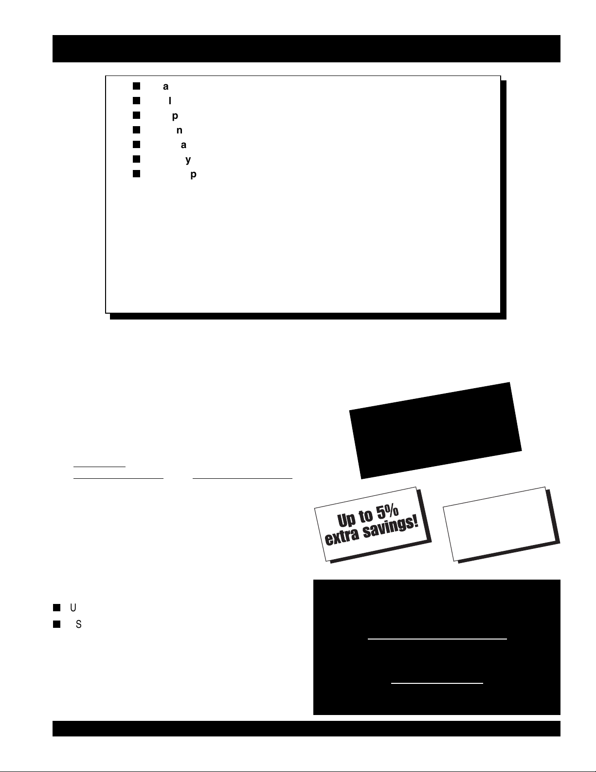
PARTS ORDERING PROCEDURES
n
Dealer account number
n
Dealer name and address
n
Shipping address (if different than billing address)
n
Return fax number
n
Applicable model number
n
Quantity, part number and description of each part
n
Specify preferred method of shipment:
UPS Ground
•
UPS Second Day or Third Day*
•
UPS Next Day*
•
Federal Express Priority One (please provide us with your Federal
•
Express account number)*
Airborne Express*
•
Truck or parcel post
•
*Normally shipped the same day the order is received, if prior to 2PM west coast time.
Earn Extra Discounts when
you order by FAX!
All parts orders which include complete part numbers
and are received by fax qualify for the following extra
discounts:
Number of
line items ordered Additional Discount
1-9 items 3%
10+ items** 5%
Get special freight allowances
when you order 10 or more
line items via FAX!**
n
UPS Ground Service at no charge for freight
n
PS Third Day Service at one-half of actual freight cost
No other allowances on freight shipped by any other carrier.
**Common nuts, bolts and washers (all items under $1.00 list price)
do not count towards the 10+ line items.
Extra Fax DiscountExtra Fax Discount
Extra Fax Discount
Extra Fax DiscountExtra Fax Discount
for Domestic USAfor Domestic USA
for Domestic USA
for Domestic USAfor Domestic USA
Dealers OnlyDealers Only
Dealers Only
Dealers OnlyDealers Only
UPS
Special
For faxed orders only
Now! Direct TOLL-FREE access
to our Parts Department!
Toll-free nationwide:
800-421-1244
Toll-free FAX:
*DISCOUNTS ARE SUBJECT TO CHANGE*
Fax order discount and UPS special programs revised June 1, 1995
MTR-60L — PARTS & OPERATION MANUAL — REV. #7 (06/26/01) — PAGE 5
800/6-PARTS-7 • 800-672-7877
Page 6
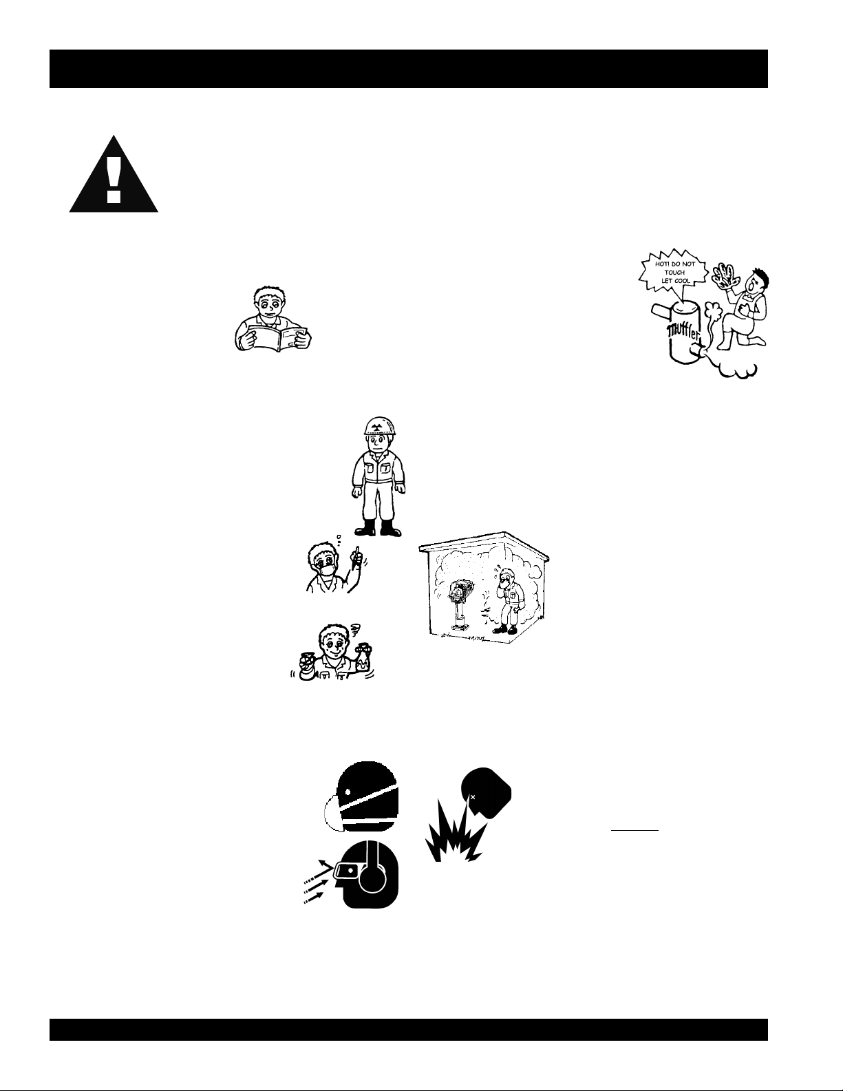
RULES FOR SAFE OPERATION
■
CAUTION:
Failure to follow instructions in this manual
may lead to serious injury or even death!
This equipment is to be operated by trained
and qualified personnel only! This
equipment is for industrial use only.
The following safety guidelines should always be used when
operating the MTR-60L Tamping Rammer:
GENERAL SAFETY
■
DO NOT operate or service this equipment before
reading this entire manual.
■
This equipment should not be operated by persons
under 18 years of age.
■
NEVER operate this equipment without proper
protective clothing, shatterproof glasses, steeltoed boots and other protective devices required
by the job.
■
NEVER operate this equipment when not
feeling well due to fatigue, illness or taking
medicine.
■
NEVER operate this equipment under the
influence or drugs or alcohol.
Whenever necessary, replace nameplate, operation and
safety decals when they become difficult read.
■
Manufacture does not assume responsibility for any accident
due to equipment modifications.
■
NEVER use accessories or attachments, which are not
recommended by Multiquip for this equipment. Damage to
the equipment and/or injury to user may result.
■
NEVER touch the hot exhaust manifold,
muffler or cylinder. Allow these parts to
cool before servicing engine or rammer.
■
High Temperatures – Allow the engine to cool before adding
fuel or performing service and maintenance functions. Contact
hot
with
■
The engine section of this rammer requires an adequate free
flow of cooling air. NEVER operate the rammer in any
components can cause serious burns.
enclosed or narrow area where free
flow of the air is restricted. If the air
flow is restricted it will cause serious
damage to the rammer or engine and
may cause injury to people.
Remember the rammer's engine
gives off DEADLY carbon monoxide
gas.
■
ALWAYS check the machine for loosened threads or bolts
before starting.
■
ALWAYS wear proper respiratory (mask),
hearing and eye protection equipment when
operating the rammer.
PAGE 6 — MTR-60L — PARTS & OPERATION MANUAL — REV. #7 (06/26/01)
■
ALWAYS refuel in a well-ventilated area, away from sparks
and open flames.
■
ALWAYS use extreme caution when
working with flammable liquids. When
refueling, stop the engine and allow it to
cool. DO NOT
machine. Fire or explosion could result from
fuel vapors, or if fuel is spilled on a hot
■
NEVER operate the rammer in an explosive atmosphere or
near combustible materials. An explosion or fire could result
causing severe
bodily harm or even death.
smoke around or near the
Page 7

■
NEVER Run engine without air filter. Severe engine damage
may occur.
■
Always service air cleaner frequently to prevent poor combustion
and engine damage.
■
Always be sure the operator is familiar with proper safety
precautions and operations techniques before using rammer.
■
Always store equipment properly when it is not being used.
Equipment should be stored in a clean, dry location out of the
reach of children.
■
NEVER use accessories or attachments, which are not
recommended by Multiquip for this equipment. Damage to the
equipment and/or injury to user may result.
■
NEVER Run engine without air cleaner. Severe engine damage
may occur.
■
Always read, understand, and follow procedures in Operator’s
Manual before attempting to operate equipment.
■
Refer to the
technical questions or information
ROBIN Engine Owner's Manual
for engine
recommended by Multiquip
Transporting
■
■
■
■
Emergencies
■
Always know the location of the nearest
and
Also know the phone numbers of the nearest
doctor
invaluable in the case of an emergency.
Maintenance Safety
■
■
for this equipment. Damage to the equipment and/or injury to
user may result.
■
RULES FOR SAFE OPERATION
Always shutdown engine before transporting.
Tighten fuel tank cap securely and close fuel cock to prevent
fuel from spilling.
Drain fuel when transporting rammer over long distances
or bad roads.
When placing the rammer inside a truck-bed for transport,
always tie-down the rammer in the upright position.
fire extinguisher
first aid kit
and
NEVER lubricate components or attempt service on a
running machine.
Always allow the machine a proper amount of time to cool
before servicing.
Keep the machinery in proper running condition.
. Know the location of the nearest telephone.
fire department
ambulance
. This information will be
,
■
Fix damage to the machine immediately and always replace
broken parts and decals which are missing or difficult to
read.
■
Dispose of hazardous waste properly. Examples of
potentially hazardous waste are used motor oil, fuel and
fuel filters.
■
DO NOT use food or plastic containers to dispose of
hazardous waste.
MTR-60L — PARTS & OPERATION MANUAL — REV. #7 (06/26/01) — PAGE 7
Page 8
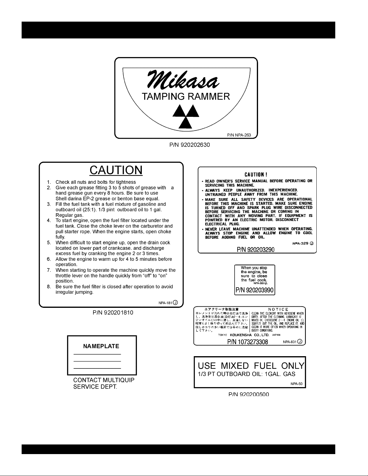
OPERATION AND SAFETY DECALS
PAGE 8 — MTR-60L — PARTS & OPERATION MANUAL — REV. #7 (06/26/01)
Page 9

Definition of Tamping Rammer
The Mikasa MTR-60L tamping rammer is a powerful compacting
tool capable of applying a tremendous force in consecutive
impacts to a soil surface. Its applications include soil compacting
for road, embankments and reservoirs as well as backfilling for
gas pipelines, water pipelines and cable installation work.
NOTE
Narrow extension shoe
accessories are available from
MQ.
The impact force of the MTR-60L levels and uniformly compacts
voids between soil particles to increase dry density.
Circular motion is converted to create impact force. The MTR60L tamping rammer develops a powerful compacting force at
the foot of the rammer. To maintain optimum performance, proper
operation and service are essential.
Construction of Tamping Rammer
GENERAL INFORMATION
The Mikasa MTR-60L Tamping Rammer is equipped with an
Robin air cooled, four cycle gasoline engine. Transmission of
the power takes place by increasing the engine speed to engage
the centrifugal clutch.
Rammer Gearbox and Spring Cylinder
The Mikasa MTR-60L uses an grease lubrication system. Always
apply grease to all grease fittings every 8 hours of operation.
(Shell Darina EP2 or Equivalent).
Controls
Before starting the MTR-60L Tamping Rammer, identify and
understand the function of the controls, see Figure 1 on page 11.
MTR-60L — PARTS & OPERATION MANUAL — REV. #7 (06/26/01) — PAGE 9
Page 10

MTR-60L — SPECIFICATIONS
LEDOM)cirtem(.S.UL06-RTM
thgieHllarevO)mm000,1(.ni5.93
pirGeldnaHfothgieH )mm059-048(.xorppa.ni61/3-73.ni33
htdiWllarevO)mm004(ni57.52
htgneLrevO)mm006(ni26.32
snoisnemiDetalP )mm033x582(.ni31x61/1-11
etunim/swolB006
aerAgnipmaTruohrep)2m002(.tf351,2
ecroFtcapmI)wolb/gk279(wolb/.sbl041,2
hctulClagufirtneCcitamotuA
thgieWgnitarepO)gk06(.sbl531
snoitacificepSremmaRL06-RTM.1elbaTsnoitacificepSremmaRL06-RTM.1elbaT
snoitacificepSremmaRL06-RTM.1elbaTsnoitacificepSremmaRL06-RTM.1elbaT
snoitacificepSremmaRL06-RTM.1elbaT
snoitacificepSenignEDTSG80-CEniboR.2elbaT
LEDOMENIGNEDTSG80-CENIBOR
epyTenignEenilosaGekortS2delooC-riA
ekortSXeroB)mm04x05(.ni23/7-1x23/13-1
tnemecalpsiDnotsiP)cc5.87(.ni.uc21.5
tuptuO.xaM)WK8.1(mpr006,3/ph4.2
oitaRnoisserpmoC1:5.6
tuptuOdetaRsuounitnoCmpr000,4/sp8.1
tuptuO.xaMmpr005,5/sp3.3
euqroT.xaMmpr006,3)m-gk15.0(bl-tf7.3
metsySgnilooCdelooC-riA
metsySnoitacirbuL metsySgniyarpSliOnoitacirbuL-leuF
leuF1liO:23enilosaG
thgieWyrD)gk4.7(.sbl3.61
gulPkrapSSH6-BKGN
metsySgnitratSretratSlioceR
NOTE
Specifications are general and are subject to change without notice. If exact
measurements are required, equipment should be weighed and measured.
PAGE 10 — MTR-60L — PARTS & OPERATION MANUAL — REV. #7 (06/26/01)
Page 11
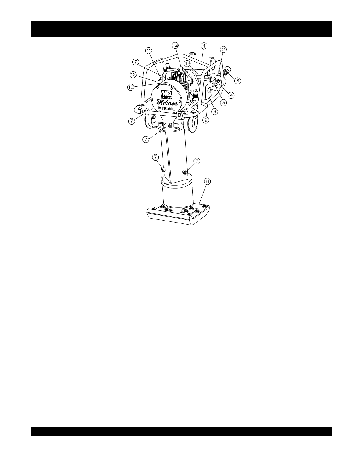
MTR-60L — CONTROLS AND COMPONENTS
Figure 1. MTR-60L Tamping Rammer
Figure 1 shows the location of the controls and components
for the MTR-60L Tamping Rammer. The functions of each
control is described below:
1. Fuel Tank/Cap – Remove this cap to add fuel. Tank holds
.39 gallons (1.5 liters ) unleaded. Mix 32:1 ratio with
outboard motor oil.
2. Throttle Lever – Controls engine speed and the tamping
action of the rammer.
3. Handle – To operate rammer
firmly.
4. Fuel Shut-Off Valve – Supplies fuel from the fuel tank to
the engine. To begin fuel flow move the fuel shut-off valve
downward.
5. Choke Lever – Used when starting the engine. Normally
used in cold weather conditions. In cold weather turn the
choke lever to the fully closed position, in warm weather
set choke lever half way or completely open.
6. Engine Air Cleaner – Prevents dirt and other debris
from entering the engine.
GRIP
handle assembly
8. Foot– Laminated wood with tempered steel plate for
superior shock absorption.
9. Fuel Valve – Open this valve to remove excess fuel from
the carburetor or crankcase.
10. Nameplate – Displays information regarding the rammer.
11. Muffler– Used to reduce noise and emissions.
12. Recoil Starting Handle – Used when starting the engine.
Pull starter handle sharply and quickly, then return
starter handle to starter case before releasing.
13. Engine Stop Switch – Controls the starting and stopping
of the engine. Switch must be in the "ON" position when
starting the engine.
14. Spark Plug – Provides spark to the ignition system,
replace with engine manufactures recommended type
spark plug.
7. Grease Fill Plugs – Grease these plugs to lubricate the
top and bottom mechanical component ends of the
rammer.
MTR-60L — PARTS & OPERATION MANUAL — REV. #7 (06/26/01) — PAGE 11
Page 12
We strongly recommend that you study this Operational Manual.
Proper maintenance and operation is essential for long life and
durability of your rammer.
1. Before operating
The rammer should be greased every two weeks (normal
1-1.
use) days.
(PART#GS2).
Thermatex, both have a bentone base with a EP-2 rating.
inferior type grease is used, the grease could become too thick
or too thin due to change in temperature and improper lubrication
may result.
1-2.
Use a well blended mixture of fuel ( 32 parts gasoline: 1 part 2cycle outboard oil).
High test ethyl gasoline is not recommended.
the gasoline should be a good grade of two-cycle or outboard
motor oil (Fig. 1).
TYPE MOTOR OIL.
1-3.
located in the fuel tank is used.
is installed in the fuel tank cap as fuel may splash out of the tank
due to vibration.
1-4.
1-5.
should be paid to cleaning the spindle rod and guide spindle
(located underneath the protective sleeve) and the recoil starter.
(Figs. 4 and 5.)
2. Starting
2-1.
(Fig. 6).
2-2.
“off” position.
In cold weather, start the unit with the choke in the fully closed
position.
can be started with the choke halfway or completely open
(Fig.7).
2-3.
NOTE: Do not pull the starter rope all the way to the end and do
not let the starter rope snap back as damage may result (Fig.8).
2-4.
the fully open position.
low speed prior to operating the rammer.
2-5.
plug for excessive carbon or excess fuel on the spark plug.
Clean and replace the spark plug as necessary.
is flooded or the crank case is loaded with excess fuel, open the
drain cock as shown in (Fig. 9) and drain out excess fuel.
Be sure to use MQ HIGH TEMPERATURE GREASE
Equivalent greases are Shell Darina or Texaco
If an
The rammer is equipped with a two-cycle gasoline engine.
A regular grade gasoline should be used.
The oil used with
DO NOT USE REGULAR AUTOMOTIVE-
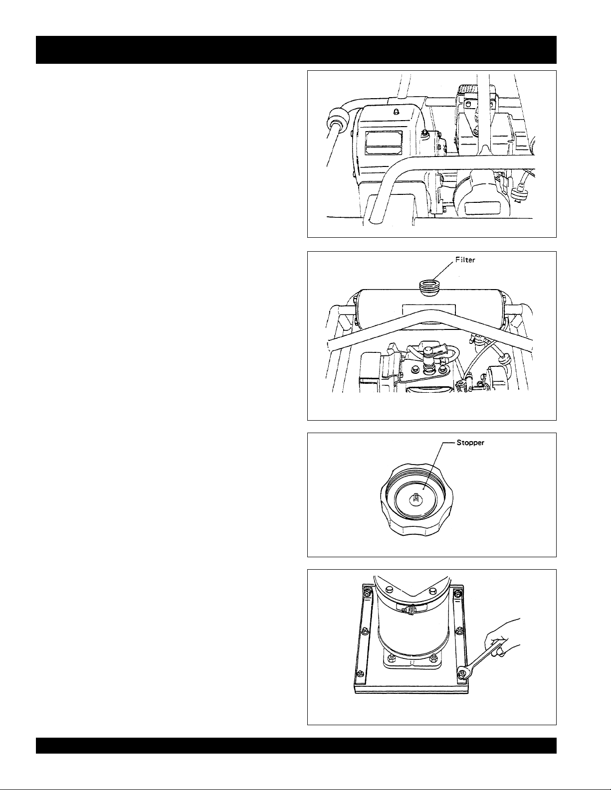
When filling the rammer with fuel, be sure that the fuel filter
Make sure that the leak stopper
(Figs. 2 and 3.)
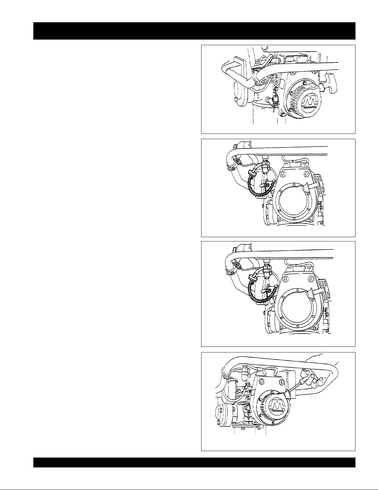
Check all the screws and bolts for tightness.
Clean all mud and dirt from the rammer. Particular attention
Turn the fuel on by moving the fuel cock lever downward
Close the choke lever and move the throttle lever to the
The choke is closed by moving the lever upward.
In summer time or when the engine is warm,
Forcefully pull the recoil starter rope to start the engine.
As soon as the engine starts, gradually open the choke to
Let the engine idle for 2 to 3 minutes at
If the engine does not start, remove and
check the spark
the unit
If the carburetor
Fig. 2 — Filter the mixed gasoline with filter
Fig. 3 — Do not forget to install the leak stopper
MTR-60L — OPERATION
Fig. 1
Fig. 4 — Check all bolts for tightness
PAGE 12 — MTR-60L — PARTS & OPERATION MANUAL — REV. #7 (06/26/01)
Page 13
3. Operation
3-1.
Move the throttle lever (Figure 10) from the “off” to the “on “
position.
“on” position (Fig. 10).
result in damage to the clutch or springs.
3-2.
times per minute at an engine speed of 4000 rpm.
Increasing the engine speed above the recommended operating
engine speed will not increase the effectiveness of the rammer.
Impact actually decreases
a tamping effect.
rammer over hard surfaces such as concrete and asphalt are
not recommended as damage to the machine may result.
3-3.
not allow the rammer to operate smoothly.
warmed by moving the throttle lever from the “on” to the “off”
position several times until the grease is heated and the rammer
operates smoothly.
3-4.
increase the travel speed of the rammer, push down lightly on
the handle. Open blows or running the rammer without contacting
the soil is not recommended.
3.5.
may be greased daily as paragraph 5-2; however, weekly
greasing is sufficient.
Make sure that the throttle lever is moved to the fully
Operating the rammer at half speeds can
The rammer is designed to tamp the ground 550 to 600
NOTE:
as a resonance is created rather than
Damage can result to the unit. Running the
In cold weather, the grease in the rammer is stiff and may
The tamper can be
The rammer is designed to travel forward while tamping. To
Check for oil leaks and retighten bolts.
The tamping rammer
MTR-60L — OPERATION
Fig. 5 — Clean around the recoil starter
Fig. 6 — Move the fuel cock downwards
4. Stopping the engine
Turn the throttle lever to the “idle” position and allow the
4-1.
engine to run at an idle speed for 2 to 3 minutes to allow the
temperature of the engine to cool, then stop the engine by pushing
the “stop” button (Fig. 11).
5. Service
DAILY
5-1.
Thoroughly remove mud, dirt, and oil from the machine.
the air cleaner element and clean or replace it as necessary.
Check all bolts for tightness.
WEEKLY (every 50 hours)
5-2.
Remove the air cleaner element and wash it in a neutral detergent
solution.
the element with a two-cycle engine fuel mix and squeeze out the
excess moisture.
conditions, the tamping rammer may be greased daily.
conditions, add 6 shots of grease to all three lubrication points every
2 weeks.
(PART #GRS2) or it’s generic equivalent Bentone base EP#2 grease.
(Shell Darina EP2)
Shake out excess moisture and dry the element.
Reinstall the air cleaner element.
Be sure to use MQ HIGH TEMPERATURE GREASE
Check
Lubricate
Under extreme
Under normal
Fig. 7 — Closing the choke lever
Fig. 8 — Pull the grip forcibly after slight
resistance is felt
MTR-60L — PARTS & OPERATION MANUAL — REV. #7 (06/26/01) — PAGE 13
Page 14
5-3. MONTHLY (every 200 hours)
Clean the fuel filter cup and check all nuts and bolts for tightness.
5-4.
STORAGE
When storing the rammer for long periods of time, thoroughly
drain all fuel from the fuel line, carburetor, and engine.
the spark plug and put a few drops of motor oil into the cylinder
and crank the engine several times by hand.
of the rammer with an oil-moistened cloth.
clean dry place.
6. Dismantling the tamping rammer
When dismantling the machine, be sure to disassemble in a
clean, dust-free area.
6-1.
Removal of the Foot: Remove the protection sleeve
(#17P17), band (#18P17), and then loosen the four nuts
(#30P17) of the foot plate (#22P17), and remove bolts (#27P17).
The foot can now be removed by lightly tapping it.
Removal of the Foot Plate: After removing the foot, remove
6-2.
the lock washer (#23P17) by loosening the bolts (#24P17).
Then remove the foot plate (#22P17) from the spindle rod
(#7P17).
Clean the outside
Cover and store in a
Remove
MTR-60L — OPERATION
Fig. 9 — Drain plug
6-3. Replacement of the Springs:
a. Loosen the four bolts which connect the guide cylinder and
crankcase . Separate them, and locate the cylinder pin.
b. Remove the cylinder pin by taking off the stop rings fitted to
the cylinder cap (bottom), and the spring cylinder and the
crankcase can be completely separated.
c. Next, remove the four bolts which connect the double guide
and guide cylinder.
removed with the foot plate.
d. Remove the cylinder cap (bottom) by loosening it gradually.
CAUTION: Be careful when removing the cylinder cap (bottom),
as springs may spring out.
in set only.
Replacement of the Crank Gear: Remove cylinder pin,
6-4.
guide cylinder, crankcase, front cover, bolt, and lock washer,
and connecting rod.
Hexagonal socket bolt , hit the crank gear from engine side,
and remove.
Replacement of Clutch: The engine, and the Clutch Assy.
6-5.
can be taken off by loosening bolts.
shoe, take off the washer to prevent turning the front clutch
guide, clutch guide , and clutch spring.
as one complete set.
The complete spring cylinder can be
Spring replacement should be made
After removing bearing cover and
When removing the clutch
Replace the clutch shoes
Fig. 10 — Moving the throttle lever to the “ON”
position quickly
Fig. 11 — Stop button
PAGE 14 — MTR-60L — PARTS & OPERATION MANUAL — REV. #7 (06/26/01)
Fig. 12
Page 15

Fig. 13
MTR-60L — OPERATION
Fig. 14
6-6. Replacement of Pinion Gear:
Tap on the head of pinion using a hammer to pull out the pinion
(#22P15) including 23-26.
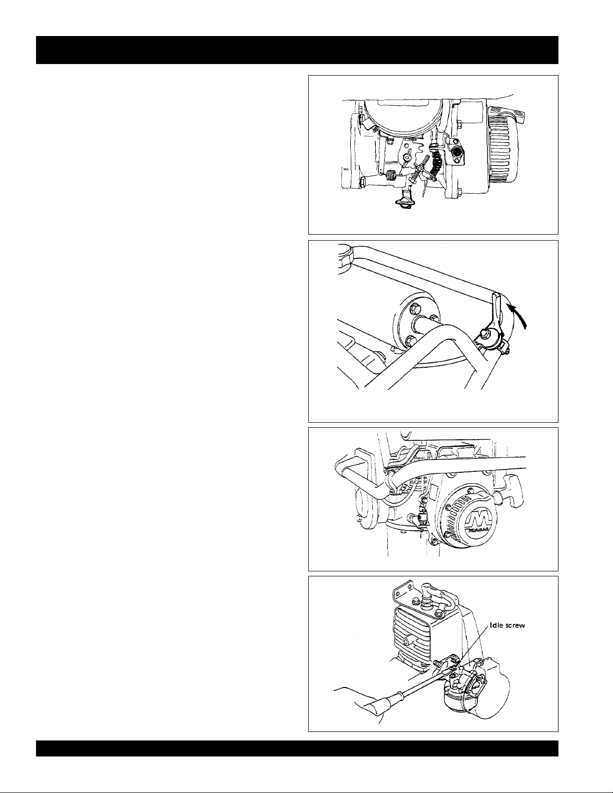
7. Speed adjustment
Idle adjustment
7-1.
7-1-1
Adjust idle when engine is warm.
7-1-2
With the throttle in a “off” position, adjust idle screw
(Fig 12) to approximately 1,200+- 100.
7-2. Pilot adjustment
7-2-1
Turn pilot screw (Fig. 13 ) to closed position. Open
approximately one full turn for smooth engine idling.
7-3. High speed adjustment. The rammer should operate at
3800 rpm at full operating speed .
adjusted simply by adjusting the adjusting screw and nut to the
proper stop position as shown in (Fig. 14).
remove the governor lever or governor shaft unless absolutely
necessary for disassembly.
measure the dimension “L” of the adjusting screw and when
reassembled, set the adjusting screw to the “L” dimension.
Remove engine (#30P15).
Proper high speed can be
NOTE: Do not
When disassembling is necessary,
MTR-60L — PARTS & OPERATION MANUAL — REV. #7 (06/26/01) — PAGE 15
Page 16

MTR-60L — TROUBLESHOOTING GUIDE
GNITOOHSELBUORTENIGNE.4ELBAT
MOTPMYS MELBORPELBISSOP NOITULOS
tratsottluciffiD
?degdirbnobracgulpkrapS .gulpkrapSecalpeR
.)elbacnoisnethgih
rewoP(.etingitonlliw TON
noisserpmoc(setingi )lamron .
noisserpmoc(setingi wol .)
yrotcafsitastonnoitarepO
gulpkrapstubelbaliavasileuF
taelbaliavarewoP(.etingitonlliw
?srotalusni
gulpkrapstubelbaliavasileuF
.)elbacnoisnethgihtaelbaliava
?stisoped
gulpkrapsdnaelbaliavasileuF
?)tsud
gulpkrapsdnaelbaliavasileuF
?nrowrednilyC .dedeensasgnirdna,notsip,rednilycecalpeR
?noitingitatisopednobraC .troptsuahxednarelffumnaelC
evitcefedoteudtiucrictrohS
?pagkrapsreporpmI .pagtcerrocehtotpaggulpkrapsteS
?hctiwspotstatiucrictrohS .evitcefedfihctiwspotsecalpeR.tiucrichctiwspotskcehC
?evitcefedliocnoitingI .liocnoitingiecalpeR
nobrachtiwdeggolcrelffuM
?etauqedanisiytilauqleufdexiM .erutximliootleufkcehC
,retaw(etauqedaniesunileuF
?deggolcrenaelCriA .renaelcriaecalperronaelC
?teksagdaehrednilycevitcefeD .teksagdaehecalperrostlobdaehrednilycnethgiT
?esoolgulpkrapS .gulpkrapsnehgiT
.srotalusniecalpeR
.relffumecalperronaelC
.leufhserfhtiwecalperdnametysleufhsulF
?deggolcrenaelcriA .ecalpeR/naelC
elbaliavarewophguonetoN
-ssimon,lamronnoisserpmoc(
.)gnirif
elbaliavarewophguonetoN
-ssim,lamronnoisserpmoc(
.)gnirif
?)tsud
.staehrevoenignE
?enilleufniriA .enilleufmorf)riaevomer(deelB
?reporpmirebmahc
?evitcefedliocnoitingI .leufhserfhtiwecalperdnametysleufhsulF
?rebmahcnoitsubmoc
.nobrac
taolfrotaerubracnilevelleuF
?rednilycnistisopednobraC .dedeensasgnirdna,notsip,rednilycecalperronaelC
?strohsnetfogulpnoitingI .noitinginaelc,seriwnoitingiecalpeR
,retaw(etauqedaniesunileuF
?etauqedanisiytilauqleufdexiM .erutximliootleufkcehC
ninoitsopednobracevissecxE
htiwdeggolcrelffumrotsuahxE
?tcerrocnieulavtaehgulpkrapS .gulpkrapsepyttcerrochtiwgulpkrapsecalpeR
taolfrotaerubractsujdA
.leufhserfhtiwecalperdnametysleufhsulF
.esacknarcecalperronaelC
.relffumecalperronaelC
PAGE 16 — MTR-60L — PARTS & OPERATION MANUAL — REV. #7 (06/26/01)
Page 17

MTR-60L — TROUBLESHOOTING GUIDE
ENGINEENGINE
ENGINE
ENGINEENGINE
MOTPMYS MELBORPELBISSOP NOITULOS
yrotcafsitastonnoitarepO
?reporpmitnemtsujdaronrevoG .reveltcerrocotronrevogtsujdA
?evitcefedgnirpsronrevoG .noitingiecalperronaelC
.setautculfdeepslanoitatoR
?citarrewolfleuF .gnitnevreporprofpacleufkcehC.enilleufkcehC
?enilnoitcushguorhtninekatriA .enilnoitcuskcehC
?trapgnitatornitsuD
gnikrowtonretratslioceR
.ylreporp
?eruliafgnirpsgnirpS
.nekorbrodeyarfepoR .eporretratsecalpeR
)deunitnoc(GNITOOHSELBUORTENIGNE.4ELBAT
.ylbmessaretratsliocernaelC
.gnirpslairpsecalpeR
GNITOOHSELBUORTREMMAR.5ELBAT
MOTPMYS MELBORPELBISSOP NOITULOS
revelelttorhtfodeepsgnitarepO
?tesyltcerrocnisi
?ssecxeniesaerG kcalesuacdnanedrahyamsepytesaergdexiM.esaergrevotonoD
.noitacirbulfo
tonediutilpmatubsetatorenignE
.ekirtstonseodromrofinu
?spilshctulC .hctulcecalpeR
?eruliaFhctulC .dedeensahctulc/sgnirpsecalpeR
?reporpmienignefodeepS .gnittesMPRgnitarepotcerrocotdeepsenignetsujdA
gnirpSremmaRnekorB .dedeensaWBsgnirps/sgnirpsecalpeR/riapeR
.noitisopdeepsllufotrevelelttorhtteS
MTR-60L — PARTS & OPERATION MANUAL — REV. #7 (06/26/01) — PAGE 17
Page 18

EXPLANATION OF CODE IN REMARKS COLUMN
How to read the marks and remarks used in this parts
book.
Items Found In the “Remarks” Column
Serial Numbers-Where indicated, this indicates a serial
number range (inclusive) where a particular part is used.
Model Number-Where indicated, this shows that the
corresponding part is utilized only with this specific model
number or model number variant.
Items Found In the “Items Number” Column
All parts with same symbol in the number column,
■
, belong to the same assembly or kit.
If more than one of the same reference number is
listed, the last one listed indicates newest (or latest)
part avaliable.
, #, +, %, or
*
NOTE
NOTE
The contents of this catalog are
subject to change without notice
PAGE 18 — MTR-60L — PARTS & OPERATION MANUAL — REV. #7 (06/26/01)
.
Page 19

MTR-60L — SUGGESTED SPARE PARTS
MTR-60L Mikasa Rammer
1 to 3 Units
Qty. .... PIN ..................... Description
10 ....... GRS2.................. Grease, high temp.
3 ......... 0650140031 ....... Spark plug
1 ......... 956300060 ......... Lever, throttle assy.
1 ......... 301010900 ......... Throttle wire
2 ......... 505015060 ......... Nipple, A-grease
1 ......... 301910081 ......... Tank cap assy.
1 ......... 954300390 ......... Fuel cock assembly
10 ....... 301419750 ......... Filter, in-line fuel
1 ......... 959401750 ......... Stopper for wire
1 ......... 402010110 ......... Spring, return
1 ......... 1293500403 ....... Gasket, muffler
1 ......... 0521060100 ....... Banjo
1 ......... 2096233508 ....... Bolt Banjo
1 ......... 2076234508 ....... Washer
5 ......... 1063260207 ....... Element, air cleaner
1 ......... 0669900207 ....... Button, stop (S/N C-5084 & Below)
1 ......... 0662009720 ....... Switch, stop (S/N C-5085 & Above)
MTR-60L Mikasa Rammer
5 to 10 Units
Qty. .... PIN ..................... Description
10 ....... GRS2.................. Grease, high temp.
10 ....... 0650140031 ....... Spark plug
2 ......... 956300060 ......... Lever, throttle assy.
2 ......... 301010900 ......... Throttle wire
4 ......... 301010810 ......... Rubber coupling
3 ......... 0643000101 ....... Drain cock
6 ......... 505015060 ......... Nipple, A-grease
2 ......... 301910081 ......... Tank cap assembly
3 ......... 954300390 ......... Fuel cock assembly
5 ......... 301419750 ......... Filter, in-line fuel
3 ......... 959401750 ......... Stopper for wire
3 ......... 402010110 ......... Spring, return
3 ......... 1293500403 ....... Gasket, muffler
2 ......... 5802023000 ....... Ring set
3 ......... 0521060100 ....... Banjo
3 ......... 2096233508 ....... Bolt Banjo
3 ......... 2076234508 ....... Washer
20 ....... 1063260207 ....... Element, air cleaner
3 ......... 0669900207 ....... Button, stop (S/N C-5084 & Below)
2 ......... EC086230 .......... Kit, carburetor
2 ......... 1299900107 ....... Gasket set
3 ......... 0662009720 ....... Switch, stop (S/N C-5085 & Above)
NOTE
Part number on this Suggested
Spare Parts List may super cede/
replace the P/N shown in the text
pages of this book.
MTR-60L Mikasa Rammer
3 to 5 Units
Qty. PIN Description
10 ..... GRS2 .................. Grease, high temp.
5 ....... 0650140031 ....... Spark plug
1 ....... 956300060 ......... Lever, throttle assy.
2 ....... 301010900 .........Throttle wire
2 ....... 301010810 ......... Rubber coupling
1 ....... 0643000101 ....... Drain cock
4 ....... 505015060 ......... Nipple, A-grease
5 ....... 301419750 ......... Filter, in-line fuel
2 ....... 954300390 ......... Fuel cock assembly
2 ....... 301910090 ......... Hose assembly fuel
2 ....... 959401750 ......... Stopper for wire
2 ....... 402010110 .........Spring, return
2 ....... 1293500403 ....... Gasket, muffler
10 ..... 1063260207 ....... Element, air cleaner
2 ....... 0669900207 ....... Button, stop (S/N C-5084 & Below)
1 ....... EC086230 .......... Kit, carburetor
2 ....... 0662009720 ....... Switch, stop (S/N C-5085 & Above)
MTR-60L Mikasa Rammer
10+ Units
Qty. PIN Description
20 ....... GRS2.................. Grease, high temp.
14 ....... 0650140031 ....... Spark plug
4 ......... 956300060 ......... Lever, throttle assy.
4 ......... 301010900 ......... Throttle wire
6 ......... 301010810 ......... Rubber coupling
4 ......... 0643000101 ....... Drain cock
8 ......... 505015060 ......... Nipple, A-grease
3 ......... 301910081 ......... Tank cap assembly
5 ......... 954300390 ......... Fuel cock assembly
10 ....... 301419750 ......... Filter, in-line fuel
5 ......... 959401750 ......... Stopper for wire
5 ......... 402010110 ......... Spring, return
5 ......... 1293500403 ....... Gasket, muffler
3 ......... 5802023000 ....... Ring set
5 ......... 0521060100 ....... Banjo
5 ......... 2096233508 ....... Bolt Banjo
5 ......... 2076234508 ....... Washer
1 ......... 5803019000 ....... Air cleaner assy.
15 ....... 1063260207 ....... Element, air cleaner
5 ......... 0669900207 ....... Button, stop (S/N C-5084 & Below)
3 ......... EC086230 .......... Kit, carburetor
3 ......... 1299900107 ....... Gasket set
5 ......... 0662009720 ....... Switch, stop (S/N C-5085 & Above)
1 ......... 301421360 ......... Clutch assembly
1 ......... 5806069000 ....... Carburetor assembly
1 ......... 5805001000 ....... Recoil starter assembly
MTR-60L — PARTS & OPERATION MANUAL — REV. #7 (06/26/01) — PAGE 19
Page 20

NAME PLATE AND DECALS
MTR-60L— NAME PLATE AND DECALS
PAGE 20 — MTR-60L — PARTS & OPERATION MANUAL — REV. #7 (06/26/01)
Page 21

MTR-60L— NAME PLATE AND DECALS
NAME PLATE AND DECALS
NO PART NO PART NAME QTY. REMARKS
1
*
2
*
3
*
5
*
6 PLATE, SERIAL NO. 1 CONTACT MQ SERVICE DEPT. W/MODEL & S/N
7
*
10 DCLMTR-60L KIT, DECAL ................................................... 1 ............ INCLUDES ITEMS W/
SEE DECAL ILLUSTRATIONS ON PAGE 7.
920200500 DECAL: MIXED FUEL 1 NPA-50
920203290 DECAL: CAUTION READ 1 NPA-329
920201810 DECAL: CAUTION 1 NPA-181
920203990 DECAL: FUEL SHUT-OFF 1 NPA-399
920202630 DECAL: MIKASA LOGO 1 NAP-263
*
MTR-60L — PARTS & OPERATION MANUAL — REV. #7 (06/26/01) — PAGE 21
Page 22

CRANK CASE AND ENGINE ASSY.
MTR-60L — CRANKCASE AND ENGINE ASSY.
PAGE 22 — MTR-60L — PARTS & OPERATION MANUAL — REV. #7 (06/26/01)
Page 23

MTR-60L — CRANKCASE AND ENGINE ASSY.
CRANK CASE AND ENGINE ASSY.
NO. PART NO. PART NAME QTY. REMARKS
1 303105230 CRANK CASE 1
1 303105232 CRANK CASE 1
2 303205980 FRONT COVER 1
3 011006015 BOLT 6X15 10
3 011706020 BOLT 6X20 H, SW 10
4 030206150 WASHER SW M6 10
8 303010040 CRANK GEAR 1
9 041006307 BEARING 6307Z 1
10 041006204 BEARING 6204Z 1
12 952400130 WASHER 9304 2
13 014208020 SOCKET HEAD BOLT 8X20 T 2
14 303010060 CONNECTING ROD 1
15 042006304 BEARING 6304ZZ 1
16 080100520 STOP RING R-52 1
19 303010070 BEARING COVER 1
22 303010084 PINION REQ. SPACER 351437750 .... 1 ............REPLACES 303010080
23 041006007 BEARING 6007Z 2
24 080200350 STOP RING S-35 2
24 080200350 STOP RING S-35 1
25 303010090 SPACER, CLUTCH DRUM/55 1
26 060504010 OIL SEAL VB-40525 1
27 351437750 SPACER 35.4-42.7-11 1
28 303010110 PACKING, BEARING COVER 1
30 911100805 ENGINE ASSY. EC08G 1
31 011208030 BOLT 8X30 ........................................... 4 ............REPLACES 011008030
32 030208200 WASHER SW M8 4
33 301420750 SPACER 15X21X4T, CLUTCH ............ 1 ............8 E/G 62990
35 301421363 CLUTCH ASSY. .................................... 1 ............INCLUDES W/# REPLACES 301421360
36# 301010210 LOCK WASHER CLUTCH 1
38# 943060020 CLUTCH GUIDE/B 1
39# 943050050 CLUTCH BOSS 1
40# 943020020 CLUTCH SHOE 4
41# 943030020 CLUTCH SPRING 2
42# 943060010 CLUTCH GUIDE/A 1
43 505015060 GREASE FITTING 3
44
45 PLATE, SERIAL NO. ............................................ORDER FROM MQ SERVICE DEPT. MODEL & S/N
*
*
*
*
*
*
920100240 DECAL (M-MARK) 1
*
DCL60 DECAL SET MTR-60L ......................... 1 ............ INCLUDES ITEMS W/
5809501000 LABEL ENGINE, EC08G 2
920100240 DECAL (M-MARK) 1
920202630 DECAL, TRADE MARK/RAMMER 1
920201810 DECAL, CAUTION, GENERAL INSTR.1
920200500 DECAL, MIXED FUEL 1
1063273808 DECAL, AIR CLEANER 1
*
MTR-60L — PARTS & OPERATION MANUAL — REV. #7 (06/26/01) — PAGE 23
Page 24

GUIDE CYLINDER AND FOOT ASSY.
MTR-60L — CYLINDER GUIDE AND FOOT ASSY.
PAGE 24 — MTR-60L — PARTS & OPERATION MANUAL — REV. #7 (06/26/01)
Page 25

MTR-60L — CYLINDER GUIDE AND FOOT ASSY.
GUIDE CYLINDER AND FOOT ASSY.
NO. PART NO. PART NAME QTY. REMARKS
1 303010230 SPRING CYLINDER ............................ 1 ............DO NOT DISASSEMBLE WITHOUT PROPER
..............................................................................TOOLS AND INTRUCTION, SPRINGS ARE IN
..............................................................................TENSION STORING POTENTIAL ENGERY, SEE
..............................................................................SERVICE / REPAIR SECTION.
2 303010240 CYLINDER CAP/TOP 1
3 303010250 CYLINDER CAP/BOTTOM 1
4 303010260 CYLINDER PIN 1
5 080100120 STOP RING R-12 2
6 303313740 MAIN SPRING A, B 2
7 303010280 SPINDLE ROD 1
8 301010310 PROTECTOR RUBBER 1
9 303010510 GUIDE CYLINDER 1
10 303010300 PACKING, GUIDE CYL. UPPER 1
11 303010310 PACKING, GUIDE CYL. LOWER 1
12 303010320 GUIDE 1
13 011008025 BOLT 8X25 H ....................................... 4 ............REPLACES 011108025
14 020108060 NUT M8 H ............................................ 4 ............ REPLACES 020108061
14 021108100 NYLON NUT M8 4
15 065103010 DUST SEAL DKI-3244710 1
16 080100450 STOP RING R-45 1
17 303010330 PROTECTION SLEEVE 1
18 303010340 BAND 1
19 011208030 BOLT 8X30 B=12 ................................. 1 ............REPLACES 013008030
20 030208200 WASHER SW M8 5
21 303010350 BUSHING 1
22#
23 301010520 LOCK WASHER H 1
24 0017212030 HEX HEAD BOLT ................................. 1 ............ REPLACES 011012030
25
26
27 015112075 SUNK HEAD BOLT 12X75H ................ 4 ............REPLACES 015112063 INCL'S ITEM W/+
28
29
30+ 021112140 NYLON NUT M12 4
31
32 030212300 WASHER SW M12 4
33
34# 303010390 GUIDE SPINDLE 1
35# 025306032 SPRING PIN ......................................... 1 ............ REPLACES 025406032
36
37
39 303910060 SPRING CYLINDER ASSY. 60L 1
40 303910030 FOOT ASSY. ........................................ 1 ............INCLUDES ITEMS W/
41 014210028 SOCKET HEAD BOLT 10X28 4
42 030210250 WASHER SW M10 4
43 505015060 GREASE FITTING 1
44 303910020 FOOT PLATE ASSY. ............................1 ............INCLUDES ITEMS W/#
**
303010370 FOOT 1
*
303010380 METAL SHEET 1
*
015110050 SUNK HEAD BOLT 10X50H 5
*
015110050 SUNK HEAD BOLT 10X50 ..................2 ............REPLACES 015110045
*
021110120 NYLON NUT M10 7
*
030210250 WASHER SW M10 7
*
303010400 FOOT FITTING 2
*
506404060 WASHER .............................................. 1 ............REPLACES 301010540
*
FOOT PLATE .......................................................NOT SERVICED SEPERATELY**SEE ITEM #44
11.25" (W) X 14 (L)
*
MTR-60L — PARTS & OPERATION MANUAL — REV. #7 (06/26/01) — PAGE 25
Page 26

TANK AND HANDLE ASSY.
MTR-60L — TANK AND HANDLE ASSY.
23-1
23-2
23-3
PAGE 26 — MTR-60L — PARTS & OPERATION MANUAL — REV. #7 (06/26/01)
Page 27

MTR-60L — TANK AND HANDLE ASSY.
TANK AND HANDLE ASSY.
NO. PART NO. PART NAME QTY. REMARKS
1 303910100 HANDLE ASS’Y W/ROLLERS ............. 1 ............ INCLUDES ITEMS W/
4 301010810 RUBBER COUPLING ..........................2 ............REPLACES 303312900
5 303010440 WASHER 11X22X3 6
6 012210050 BOLT 10X50 ......................................... 6 ............REPLACES 012010050
7 012210060 BOLT 10X58 ......................................... 6 ............REPLACES 012010058
9 030210250 SW M10 12
10 020310080 NUT M10 6
15 301010780 FUEL TANK, 1
18A 301910081 TANK CAP ASSY. ................................. 6 ............INCLUDES ITEMS W/#
18# 953404280 TANK CAP ............................................ 1 ............REPLACES 301010740
19# 301010860 LEAK STOPPER 1
20# 301010850 SPONGE 1
21# 301420050 PLATE 1
22 954405080 FUEL FILTER ....................................... 1 ............REPLACES 301010760
23 954300390 FUEL COCK ASSY. CL-TYPE.............. 1 ............INCLUDES ITEMS W/% REPLACES 301322990
23-1% 0642001410 CUP, FUEL COCK 1
23-2% 0642001420 SCREEN, FUEL COCK 1
23-3% 0642001430 RUBBER PACKING, FUEL COCK 1
25+ 301420540 PROTECT SPRING 10X180 1
26 956300060 THROTTLE LEVER 1
27 301010900 THROTTLE WIRE S335-445 1
28+ 301420730 HOSE CLAMP 11 ................................. 2 ............ REPLACES 303010490
29 959401750 WIRE STOPPER ASSY. 1
31 402010110 RETURN SPRING 1
32 920202630 DECAL, TRADE MARK/RAMMER ....... 1 ............REPLACES 920100340
33 920201810 DECAL, CAUTION 1
34 920200500 DECAL, MIXED FUEL 1
36+ 301420330 FUEL HOSE R-170 1
37+ 301419750 FUEL FILTER CP, MQ75MIC 1
38+ 303424870 FUEL HOSE R-30 1
39 030208200 WASHER SW M8 6
40 011008015 BOLT 8X15 6
42+ 301420730 HOSE CLAMP A9 2
43
44
45
46
47 959403750 RUBBER SLIP STOP 1
+ 302910080 FUEL HOSE ASSY .............................. 1 ............INCLUDES ITEMS W/+
301421840 ROLLER 4
*
011005025 BOLT 5X25 4
*
031105080 WASHER PW M5 8
*
020305040 NUT M5 ................................................ 4 ............REPLACES 020105040
*
*
MTR-60L — PARTS & OPERATION MANUAL — REV. #7 (06/26/01) — PAGE 27
Page 28

ROBIN EC-08G ENGINE — CRANKCASE AND CYLINDER ASSY.
CRANKCASE AND CYLINDER ASSY.
PAGE 28 — MTR-60L — PARTS & OPERATION MANUAL — REV. #7 (06/26/01)
Page 29

ROBIN EC-08G ENGINE — CRANKCASE AND CYLINDER ASSY.
CRANKCASE AND CYLINDER ASSY.
NO. PART NO. PART NAME QTY. REMARKS
1 5801018000 CRANKCASE COMPLETE .................. 1 ............INCLUDES ITEMS W/
2
*
3
*
4 0440200020 OIL SEAL, TC20307 1
5
*
6
*
7
*
8
*
9 5801028000 CYLINDER COMPLETE ...................... 1 ............INCLUDES ITEMS W/#, REPLACES EC08A0110
10 0105064970 STUD 2
11#+ 5801501600 PACKING (CYLINDER)........................ 1 ............REPLACES EC05A1111
12+ 1063500103 GASKET (INSULATOR) 2
13 1293290103 INSULATOR 1
14+ 1293500403 GASKET (MUFFLER) 1
15 0241029990 GROMMET .......................................... 1 ............REPLACES EC05A7102
16 0650140031 SPARK PLUG 1
17 0011406450 BOLT ASSY. 4
18 002170600 NUT 4
19 0170069960 U-NUT ..................................................4 ............REPLACES EC08A3104
20 0031006000 WASHER 4
21 030206150 SPRING WASHER ...............................4 ............REPLACES 0032006000
22 0643000101 DRAIN COCK ....................................... 1 ............REPLACES 06430-00100
23 5809501600 PROTECTOR (E/G)............................. 1 ............TO 37902
+ 1299900107 GASKET SET ....................................... 1 ............ INCLUDES ITEMS W/+
0600200010 BALL BEARING, 6004C3 1
0600200020 BALL BEARING, 6004C3 1
0440179930 OIL SEAL, TC20307 1
0440060010 OIL SEAL 1
0105064970 STUD 4
0105060050 STUD 1
REPLACES EC08S0250
*
MTR-60L — PARTS & OPERATION MANUAL — REV. #7 (06/26/01) — PAGE 29
Page 30

ROBIN EC-08G ENGINE — CRANKSHAFT AND PISTON ASSY.
CRANKSHAFT AND PISTON ASSY.
PAGE 30 — MTR-60L — PARTS & OPERATION MANUAL — REV. #7 (06/26/01)
Page 31

ROBIN EC-08G ENGINE — CRANKSHAFT AND PISTON ASSY.
CRANKSHAFT AND PISTON ASSY.
NO. PART NO. PART NAME QTY. REMARKS
1 5802008000 CRANKSHAFT COMPL....................... 1 ............BEFORE S/N U-7419 REPLACES EC08A0205A
1 5802016001 CRANKSHAFT COMPL. ...................... 1 ............FROM S/N U-7419
2 5802023000 PISTON RING SET .............................. 1 ............REPLACES EC08AS0100
3 5802500600 PISTON ................................................1 ............REPLACES EC08A2104A
4 5802500700 PISTON PIN ......................................... 1 ............REPLACES EC08A2105A
5 0565119990 CLIP 2
6 0610120010 NEEDLE BEARING 1
7 0053204201 WOODRUFF KEY 1
8 0200080030 WASHER 1
9 1294170322 GOVERNOR PLATE UNIT 1
10 5514500100 GOVERNOR SLEEVE .........................1 ............REPLACES EC05A4102
11 0230230020 SPACER 0-4
12 0039310000 NUT ......................................................1 ............REPLACES 0021810000
13 030206150 WASHER 1
14 0032005000 SPRING WASHER 3
15 030206150 SPRING WASHER 1
16 0043105080 SCREW (PAN HEAD) 3
17 0053204201 WOODRUFF KEY 1
18 352010010 LOCK NUT ........................................... 1 ............REPLACES 301010960
MTR-60L — PARTS & OPERATION MANUAL — REV. #7 (06/26/01) — PAGE 31
Page 32

GOVERNOR ASSY.
ROBIN EC-08G ENGINE — GOVERNOR ASSY.
19
20
PAGE 32 — MTR-60L — PARTS & OPERATION MANUAL — REV. #7 (06/26/01)
Page 33

ROBIN EC-08G ENGINE — GOVERNOR ASSY.
GOVERNOR ASSY.
NO. PART NO. PART NAME QTY. REMARKS
1 5000841040 GOVERNOR YOKE .............................. 1 ............ REPLACES EC08A4104
2 1294220103 GOVERNOR SHAFT 1
3 1294230111 GOVERNOR LEVER COMPL. 1
4 1064280113 ROD SPRING ......................................1 ............REPLACES 1064280111
5 1054270111 GOVERNOR ROD 1
6 1294250111 GOVERNOR SPRING 1
7 0217060020 FRICTION WASHER 1
8 5514500000 GOVERNOR LEVER ...........................1 ............REPLACES EC05A4101
9 0200070010 WASHER 1
10 5514500200 STOP PLATE .......................................1 ............REPLACES EC05A4103
11 0178060010 WING NUT 1
12 1294500103 CLIP 1
13 0016506400 BOLT 1
14 0021706000 NUT 1
15 020106050 NUT ......................................................1 ............REPLACES 0022706000
16 0032003000 SPRING WASHER 2
17 030206150 SPRING WASHER 1
18 0043103050 SCREW (PAN HEAD) 2
19 0149060040 ADJUSTING SCREW 1
20 020106050 NUT 1
MTR-60L — PARTS & OPERATION MANUAL — REV. #7 (06/26/01) — PAGE 33
Page 34

ROBIN EC-08G ENGINE — MUFFLER AND BLOWER HOUSING ASSY.
MUFFLER AND BLOWER HOUSING ASSY.
PAGE 34 — MTR-60L — PARTS & OPERATION MANUAL — REV. #7 (06/26/01)
Page 35

ROBIN EC-08G ENGINE — MUFFLER AND BLOWER HOUSING ASSY.
MUFFLER AND BLOWER HOUSING ASSY.
NO. PART NO. PART NAME QTY. REMARKS
1 5515501000 CYLINDER COVER ............................. 1 ............REPLACES EC05A1110AB
2 5805500100 BLOWER HOUSING COMPL. ............ 1 ............REPLACES EC085101B
3 5515500200 GUIDE RUBBER .................................. 1 ............REPLACES EC05A5102
4 5803023000 MUFFLER ASSY. .................................1 ............ REPLACES EC080313TA
5 EC083102TA MUFFLER BRACKET 1
6 0669900207 STOP BUTTON COMPL. .................... 1 ............S/N C-5084 AND BELOW REPLACES 0662009870
6A 0662009720 SWITCH STOP .................................... 1 ............ABOVE S/N C-5084
7 0043504060 SCREW ASSY. ..................................... 2 ............S/N C-5084 AND BELOW
7A 0043304100 SCREW/WASHER ASSY. .................... 2 ............ ABOVE S/N C-5084
8 0011106200 BOLT ASSY. 4
9 0566030010 CLAMP 1
10 0016706200 BOLT ASSY (CYLINDER) 2
11 0016706160 BOLT ASSY. (MUFFLER) 2
12 0031206000 WASHER 2
13 030206150 SPRING WASHER ...............................4 ............REPLACES 0032006000
14 1507520103 CLAMP COMPL. .................................. 1 ............REPLACES EC080408
15 5809501000 LABEL (ENGINE) .................................1 ............ REPLACES EC089117
MTR-60L — PARTS & OPERATION MANUAL — REV. #7 (06/26/01) — PAGE 35
Page 36

ROBIN EC-08G ENGINE — CARBURETOR AND AIR CLEANER ASSY.
CARBURETOR AND AIR CLEANER ASSY.
34
35
PAGE 36 — MTR-60L — PARTS & OPERATION MANUAL — REV. #7 (06/26/01)
Page 37

ROBIN EC-08G ENGINE — CARBURETOR AND AIR CLEANER ASSY.
CARBURETOR AND AIR CLEANER ASSY.
NO. PART NO. PART NAME QTY. REMARKS
1 5806069000 CARBURETOR ASSY. ......................... 1 ............INCLUDES ITEMS W/# REPLACES 5806062001
2#
3#
4#
5# 1066251108 FLOAT ARM 1
6# 1066251608 PIN 1
7# 1066245508 NOZZLE (17A) ..................................... 1 ............REPLACES 1066245008
8# 1066250808 FLOAT 1
9# 1066238908 FLOAT CHAMBER BODY 1
10#
11#
12# 2066235008 GUIDE HOLDER 1
13# 2096244608 CHOKE SPRING 1
14#
15# 2096235308 STEEL BALL 1
16# 1066255408 VALVE (CHOKE) (9.5) 1
17# 5806062210 SHAFT ASSY (CHOKE)....................... 1 ............REPLACES BV18652
18#
19# 1066235708 GUIDE SCREW 1
20#
21# 1286253008 SHAFT ASSY (THROTTLE) 1
22# 2266253508 THROTTLE VALVE (200) 1
23#
24# 2096235108 SPRING WASHER CROSS SCREW 1
25# 1306235808 CROSS SCREW 2
26# 1066235808 SCREW 1
27 5803019000 AIR CLEANER ASSY. ........................... 1 ............INCLUDES ITEMS W/+ REPLACES EC08A0337
31+ 1063260207 ELEMENT SET .................................... 1 ............OPTIONAL FOAM ELEMENT UA91
32 0011305100 BOLT ASSY. ......................................... 3 ............REPLACES 0011005100
33 1063520101 LOCK WASHER 1
34 0521060100 BANJO.................................................. 1 ............REPLACES 0521060052
35
*
1066254708 PACKING 1
*
1066238108 PACKING NEEDLE 1
*
1286250008 NEEDLE VALVE (1.8) ........................... 1 ............ REPLACES 1066250308
*
1296240008 REVERSE MAIN JET (75) 1
*
2066243108 PACKING 1
*
5806083210 SEAL..................................................... 1 ............REPLACES 1066239218
*
2066244608 SPRING 2
*
1286242008 PILOT JET (37.5) 1
*
1066243608 PILOT SCREW 1
*
2076234508 WASHER, BANJO 2
*
EC086230 CARBURETOR KIT ............................. 1 ............INCLUDES ITEMS W/
*
OPITIONAL FOAM AIR CLEANER ELEMENT REQUIRES
PROPER OILING AFTER CLEANING AND GREASE
ENDS FOR PROPER SEAL IN A/C HOUSING.
MTR-60L — PARTS & OPERATION MANUAL — REV. #7 (06/26/01) — PAGE 37
Page 38

RECOIL STARTER ASSY.
ROBIN EC-08G ENGINE — RECOIL STARTER ASSY.
PAGE 38 — MTR-60L — PARTS & OPERATION MANUAL — REV. #7 (06/26/01)
Page 39

ROBIN EC-08G ENGINE — RECOIL STARTER ASSY.
RECOIL STARTER ASSY.
NO. PART NO. PART NAME QTY. REMARKS
1 5805001000 RECOIL STARTER ASSY. ...................1 ............ INCLUDES ITEMS W/
2
*
3
*
4
*
5
*
6
*
7
*
8
*
9
*
10
11
12
13 0011006100 BOLT ASSY. 3
14 0011006140 BOLT ASSY. 2
5805004020 SPIRAL SPRING .................................. 1 ............REPLACES EC08A05032
5805004030 REEL .................................................... 1 ............REPLACES EC08A05033
1295011008 STARTER ROPE ................................. 1 ............REPLACES EC0805019
5805004050 RETURN SPRING ............................... 1 ............REPLACES EC08A05035
5805004040 RATCHET ............................................1 ............REPLACES EC08A05034
5805004110 FRICTION SPRING .............................1 ............REPLACES EC08A05037
EC08A05038 FRICTION PLATE 1
5805011020 CENTER SCREW ................................ 1 ............REPLACES EC08A05036
5809501000 TRADE MARK ...................................... 1 ............REPLACES EC089117
*
5805001030 STARTER HANDLE ............................. 1 ............REPLACES EC08050110
*
EC08A050311 STARTER PULLEY 1
*
REPLACES EC080501
*
MTR-60L — PARTS & OPERATION MANUAL — REV. #7 (06/26/01) — PAGE 39
Page 40

MAGNETO ASSY.
ROBIN EC-08G ENGINE — MAGNETO ASSY.
PAGE 40 — MTR-60L — PARTS & OPERATION MANUAL — REV. #7 (06/26/01)
Page 41

ROBIN EC-08G ENGINE — MAGNETO ASSY.
MAGNETO ASSY.
NO. PART NO. PART NAME QTY. REMARKS
1 5807002000 MAGNETO COMPL. T. C. I. 1 INCLUDES W/
EC08A0701A
1 5807005001 MAGNETO COMPL. T. C. I. .................. 1 ............ INCLUDES ITEMS W/
2
*
3 0241069980 GROMMET .......................................... 1 ............REPLACES EC05A7101A
4 0655000140 SPARK PLUG CAP 1
5 0043605250 SCREW (PAN HEAD) 2
6 0851029960 VINYL PIPE .......................................... 1 ............REPLACES EC05A6121
5807007020 IGNITION COIL .................................... 1 ............REPLACES EC08A07012
BEFORE S/N U-7419 REPLACES
*
FROM S/N U-7419
*
MTR-60L — PARTS & OPERATION MANUAL — REV. #7 (06/26/01) — PAGE 41
Page 42

Effective: July 1, 2000
TERMS AND CONDITIONS OF SALE — PARTS
PAYMENT TERMS
Terms of payment for parts are net 10 days.
FREIGHT POLICY
All parts orders will be shipped collect or
prepaid with the charges added to the invoice.
All shipments are F.O.B. point of origin.
Multiquip’s responsibility ceases when a signed
manifest has been obtained from the carrier,
and any claim for shortage or damage must be
settled between the consignee and the carrier.
MINIMUM ORDER
The minimum charge for orders from Multiquip
is $15.00 net. Customers will be asked for
instructions regarding handling of orders not
meeting this requirement.
RETURNED GOODS POLICY
Return shipments will be accepted and credit
will be allowed, subject to the following
provisions:
1. A Returned Material Authorization must
be approved by Multiquip prior to shipment.
2. To obtain a Return Mater ial Authorization,
a list must be provided to Multiquip Parts
Sales that defines item numbers,
quantities, and descriptions of the items to
be returned.
a. The parts numbers and descriptions
must match the current parts price
list.
b. The list must be typed or computer
generated.
c. The list must state the reason(s) for
the return.
d. The list must reference the sales
order(s) or invoice(s) under which
the items were originally purchased.
e. The list must include the name and
phone number of the person
requesting the RMA.
3. A copy of the Return Material
Authorization must accompany the return
shipment.
4. Freight is at the sender’s expense. All
5. Parts must be in new and resalable
6. The following items are not returnable:
7. The sender will be notified of any material
8. Such material will be held for 5 working
9. Credit on returned parts will be issued at
10. In cases where an item is accepted for
11. Credit issued will be applied to future
PRICING AND REBATES
parts must be returned freight prepaid to
Multiquip’s designated receiving point.
condition, in the original Multiquip package
(if any), and with Muiltiquip part numbers
clearly marked.
a. Obsolete parts. (If an item is listed
in the parts price book as being
replaced by another item, it is
obsolete.)
b. Any parts with a limited shelf life
(such as gaskets, seals, “O” rings,
and other rubber parts) that were
purchased more than six months
prior to the return date.
c. Any line item with an extended dealer
net price of less than $5.00.
d. Special order items.
e. Electrical components.
f. Paint, chemicals, and lubricants.
g. Decals and paper products.
h. Items purchased in kits.
received that is not acceptable.
days from notification, pending
instructions. If a reply is not received
within 5 days, the material will be returned
to the sender at his expense.
dealer net price at time of the original
purchase, less a 15% restocking charge.
which the original purchase document
can not be determined, the price will be
based on the list price that was effective
twelve months prior to the RMA date.
purchases only.
Prices are subject to change without prior
notice. Price changes are effective on a specific
date and all orders received on or after that date
will be billed at the revised price. Rebates for
price declines and added charges for price
increases will not be made for stock on hand at
the time of any price change.
Multiquip reserves the right to quote and sell
direct to Government agencies, and to Original
Equipment Manufacturer accounts who use
our products as integral parts of their own
products.
SPECIAL EXPEDITING SERVICE
A $20.00 to $50.00 surcharge will be added to
the invoice for special handling including bus
shipments, insured parcel post or in cases
where Multiquip must personally deliver the
parts to the carrier.
LIMITATIONS OF SELLER’S LIABILITY
Multiquip shall not be liable here under for
damages in excess of the purchase price of the
item with respect to which damages are claimed,
and in no event shall Multiquip be liable for loss
of profit or good will or for any other special,
consequential or incidental damages.
LIMITATION OF WARRANTIES
No warranties, express or implied, are made in
connection with the sale of parts or trade
accessories nor as to any engine not
manufactured by Multiquip. Such warranties
made in connection with the sale of new,
complete units are made exclusively by a
statement of warranty packaged with such
units, and Multiquip neither assumes not
authorizes any person to assume for it any
other obligation or liability whatever in
connection with the sale of its products. A part
from such written statement of warranty, there
are no warranties, express, implied or statutory,
which extend beyond the description of the
products on the face hereof.
PAGE 42 — MTR-60L — PARTS & OPERATION MANUAL — REV. #7 (06/26/01)
Page 43

NOTE PAGE
MTR-60L — PARTS & OPERATION MANUAL — REV. #7 (06/26/01) — PAGE 43
Page 44

PARTS AND OPERATION MANUAL
HERE'S HOW TO GET HELP
PLEASE HAVE THE MODEL AND SERIAL NUMBER
ON-HAND WHEN CALLING
PARTS DEPARTMENT
800/427-1244 or 310/537-3700
FAX: 800/672-7877 or 310/637-3284
SERVICE DEPARTMENT
800/478-1244 or 310/537-3700
FAX: 310 - 537-4259
WARRANTY DEPARTMENT
800/421-1244, EXT. 279 or 310/537-3700
FAX: 310 - 537-1173
MAIN
800/421-1244 or 310/537-3700
FAX: 310 - 537-3927
MULTIQUIP INC.
POST OFFICE BOX 6254
CARSON, CA 90749
310-537-3700 • 800-421-1244
FAX: 310-537-3927
E-MAIL: mq@multiquip.com
WWW: multiquip.com
Quebec, Canada • Manchester, UK • Rio De Janiero, BR • Guadalajara, MX
Atlanta • Boise • Dallas • Houston • Newark
manufactured for Multiquip Inc.
by
MIKASA SANGYO CO., LTD. Tokyo, Japan
 Loading...