

Page 1

PARTS AND OPERATION MANUAL
OPERATION AND PARTS MANUAL
SERIES
MODEL MT-86D2
TAMPING RAMMER
(YANMAR DIESEL ENGINE)
Revision #3 (06/18/07)
To find the latest revision of this
publication, visit our website at:
www.multiquip.com
THIS MANUAL MUST ACCOMPANY THE EQUIPMENT AT ALL TIMES.
Page 2

MT-86D2 TAMPING RAMMER — PROPOSITION 65 WARNING
PAGE 2 — MT-86D2 TAMPING RAMMER — OPERATION AND PARTS MANUAL — REV. #3 (06/18/07)
Page 3

NOTE PAGE
MT-86D2 TAMPING RAMMER— OPERATION AND PARTS MANUAL — REV. #3 (06/18/07) — PAGE 3
Page 4

MT-86D2 TAMPING RAMMER — TABLE OF CONTENTS
MIKASA MT-86D —
Tamping Rammer
Proposition 65 Warning .............................................2
Table Of Contents .....................................................4
Parts Ordering Procedures .......................................5
Safety Message Alert Symbols ............................. 6-7
Rules For Safe Operation ..................................... 8-9
Operation and Safety Decals ..................................10
General Information ................................................11
Specifications ..........................................................12
Controls and Components ......................................13
Basic Engine ...........................................................14
Initial Start-up .................................................... 15-16
Operation ................................................................17
Maintenance ..................................................... 18-19
Troubleshooting ................................................ 20-21
Explanation Of Parts Section ..................................22
Suggested Spare Parts ...........................................23
Name Plate And Decals .................................... 24-25
Crankcase and Engine Assembly ..................... 26-29
Guide Cylinder and Foot Assembly .................. 30-31
Tank and Handle Assembly .............................. 32-33
YANMARL-48V6
ENGINE
Cylinder Block Assembly ................................ 34-35
Cylinder Head Assembly ................................ 36-37
Crankshaft and Camshaft Assembly ............. 38-39
Piston Assembly ............................................. 40-41
Lub.,Oil Pump and Governor Assembly ......... 42-43
Cooling and Starting Assembly ...................... 44-45
Fuel Injection Pump Assembly .......................46-47
Air Cleaner Assembly.....................................48-49
Muffler Assembly ........................................... 50-51
Tools, Labels and Gasket Set Assembly........ 52-53
Accessories Assembly ...................................54-55
Terms and Condition Of Sale
NOTE
Specification and part number are
subject to change without notice.
— Parts ................ 56
PAGE 4 — MT-86D2 TAMPING RAMMER — OPERATION AND PARTS MANUAL — REV. #3 (06/18/07)
Page 5
Effective: January 1st, 2006
Ordering parts has never been easier!
PARTS ORDERING PROCEDURES
Choose from three easy options:
Best Deal!
Order via Internet (Dealers Only):
Order parts on-line using Multiquip’s SmartEquip website!
■
View Parts Diagrams
■
Order Parts
■
Print Specification Information
Goto www.multiquip.com and click on
Order Par ts
to log in and save!
Order via Fax (Dealers Only):
All customers are welcome to order parts via Fax.
Domestic (US) Customers dial:
1-800-6-PARTS-7 (800-672-7877)
Order via Phone:
Non-Dealer Customers:
Contact your local Multiquip Dealer for
parts or call 800-427-1244 for help in
locating a dealer near you.
If you have an MQ Account, to obtain a
Username and Password, E-mail us at:
parts@multiquip.com.
To obtain an MQ Account, contact your
District Sales Manager for more information.
Use the
internet
on
Standard orders
complete part numbers.*
Fax
your order in and qualify for a 2% Discount
on
Standard orders
complete part numbers.*
Domestic (US) Dealers Call:
1-800-427-1244
and qualify for a 5% Discount
for all orders which include
for all orders which include
International Customers
their local Multiquip Representatives for
Parts Ordering information.
Note: Discounts Are Subject To Change
Note: Discounts Are Subject To Change
should contact
When ordering parts, please supply:
❒❒
❒
Dealer Account Number
❒❒
❒❒
❒
Dealer Name and Address
❒❒
❒❒
❒
Shipping Address (if different than billing address)
❒❒
❒❒
❒
Return Fax Number
❒❒
❒❒
❒
Applicable Model Number
❒❒
❒❒
❒
Quantity, Part Number and Description of Each Part
❒❒
NOTE
www.multiquip.com
All orders are treated as
and will ship the same day if received prior
to 3PM PST.
WE ACCEPT ALL MAJOR CREDIT CARDS!
MT-86D2 TAMPING RAMMER— OPERATION AND PARTS MANUAL — REV. #3 (06/18/07) — PAGE 5
❒❒
❒
Specify Preferred Method of Shipment:
❒❒
✓
UPS/Fed Ex
■
■
■ Next Day
■
Standard Orders
Priority One
Ground
Second/Third Day
✓ DHL
✓
Tr u ck
Page 6
MT-76D2 TAMPING RAMMER — SAFETY MESSAGE ALERT SYMBOLS
FOR YOUR SAFETY AND THE SAFETY OF OTHERS!
Safety precautions should be followed
at all times when operating this
equipment. Failure to read and
understand the Safety Messages and
Operating Instructions could result in
injury to yourself and others.
This Owner's Manual has been
developed to provide complete
instructions for the safe and efficient
NOTE
Before using this rammer, ensure that the operating
individual has read and understood all instructions in this
manual.
SAFETY MESSAGE ALERT SYMBOLS
The three (3) Safety Messages shown below will inform you
about potential hazards that could injure you or others. The
Safety Messages specifically address the level of exposure to
the operator, and are preceded by one of three words: DANGER,
operation of the MQ Mikasa Model
MT-86D2 Tamping Rammer. Refer to
the engine manufacturer's instructions
for data relative to its safe operation.
HAZARD SYMBOLS
Potential hazards associated with the operation of a
MT-86D2 Tamping Rammer
Symbols which appear throughout this manual, and will be
referenced in conjunction with Safety Message Alert
Symbols.
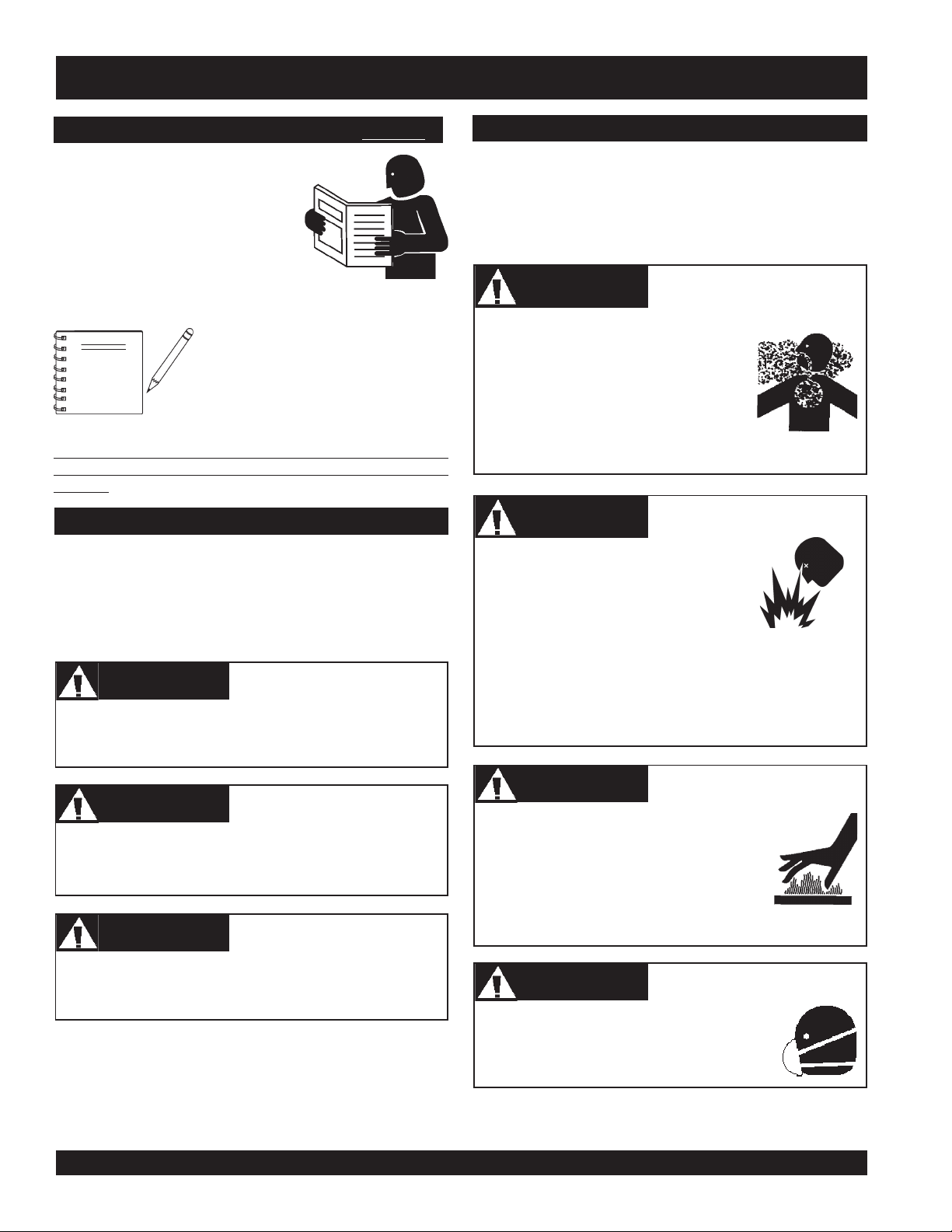
Engine exhaust gases contain
poisonous carbon monoxide. This gas
is colorless and odorless, and can
cause death if inhaled. NEVER operate
this equipment in a confined area or
enclosed structure that does not provide
ample free flow air.
Fuel is extremely flammable, and its
vapors can cause an explosion if ignited.
DO NOT start the engine near spilled
fuel or combustible fluids.
WARNINGWARNING
WARNING
WARNINGWARNING
WARNINGWARNING
WARNING
WARNINGWARNING
will be referenced with Hazard
Lethal Exhaust Gas Hazards
Explosive Fuel Hazards
DANGERDANGER
DANGER
DANGERDANGER
You WILL be
if you DO NOT follow these directions.
WARNINGWARNING
WARNING
WARNINGWARNING
You CAN be KILLED or
you DO NOT follow these directions.
CAUTICAUTI
CAUTION
CAUTICAUTI
You CAN be
these directions.
KILLED
INJURED
if you DO NOT follow
or
SERIOUSLY INJURED
SERIOUSLY INJURED
if
DO NOT fill the fuel tank while the engine is running or
hot. DO NOT overfill tank, since spilled fuel could ignite if
it comes into contact with hot engine parts or sparks from
the ignition system. Store fuel in approved containers, in
well-ventilated areas and away from sparks and flames.
WARNINGWARNING
WARNING
WARNINGWARNING
Engine components can generate extreme
heat. To prevent burns, DO NOT touch
these areas while the engine is running or
immediately after operations. Never
operate the engine with heat shields or heat
guards removed.
WARNINGWARNING
WARNING
WARNINGWARNING
ALWAYS wear approved
protection when required.
Burn Hazards
Respiratory Hazards
respiratory
PAGE 6 — MT-86D2 TAMPING RAMMER — OPERATION AND PARTS MANUAL — REV. #3 (06/18/07)
Page 7
MT-76D2 TAMPING RAMMER — SAFETY MESSAGE ALERT SYMBOLS
CAUTIONCAUTION
CAUTION
CAUTIONCAUTION
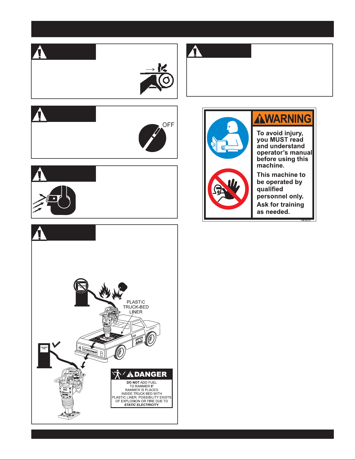
NEVER operate equipment with covers,
or guards removed. Keep fingers, hands,
hair and clothing away from all moving
parts to prevent injury.
CAUTIONCAUTION
CAUTION
CAUTIONCAUTION
ALWAYS place the ON/OFF switch in
the OFF position when the rammer is
not in use.
CAUTIONCAUTION
CAUTION
CAUTIONCAUTION
ALWAYS wear approved eye and
hearing protection.
Rotating Parts Hazards
Accidental Starting Hazards
Eye and Hearing Hazards
CAUTIONCAUTION
CAUTION
CAUTIONCAUTION
Other important messages are provided throughout this
manual to help prevent damage to your light tower, other
property, or the surrounding environment.
Equipment Damage
Hazards
DANGERDANGER
DANGER
DANGERDANGER
NEVER refuel rammer when placed in truck bed with
plastic liner. The possibility exists of explosion due to static
electricity. When adding fuel, remove rammer from truck
bed and place on ground.
Refueling Hazard
MT-86D2 TAMPING RAMMER— OPERATION AND PARTS MANUAL — REV. #3 (06/18/07) — PAGE 7
Page 8
MT-86D2 TAMPING RAMMER — RULES FOR SAFE OPERATION
■
DANGERDANGER
DANGER
DANGERDANGER
Failure to follow instructions in this manual may lead
to serious injury or even death! This equipment is to
be operated by trained and qualified personnel only!
This equipment is for industrial use only.
Read this manual!
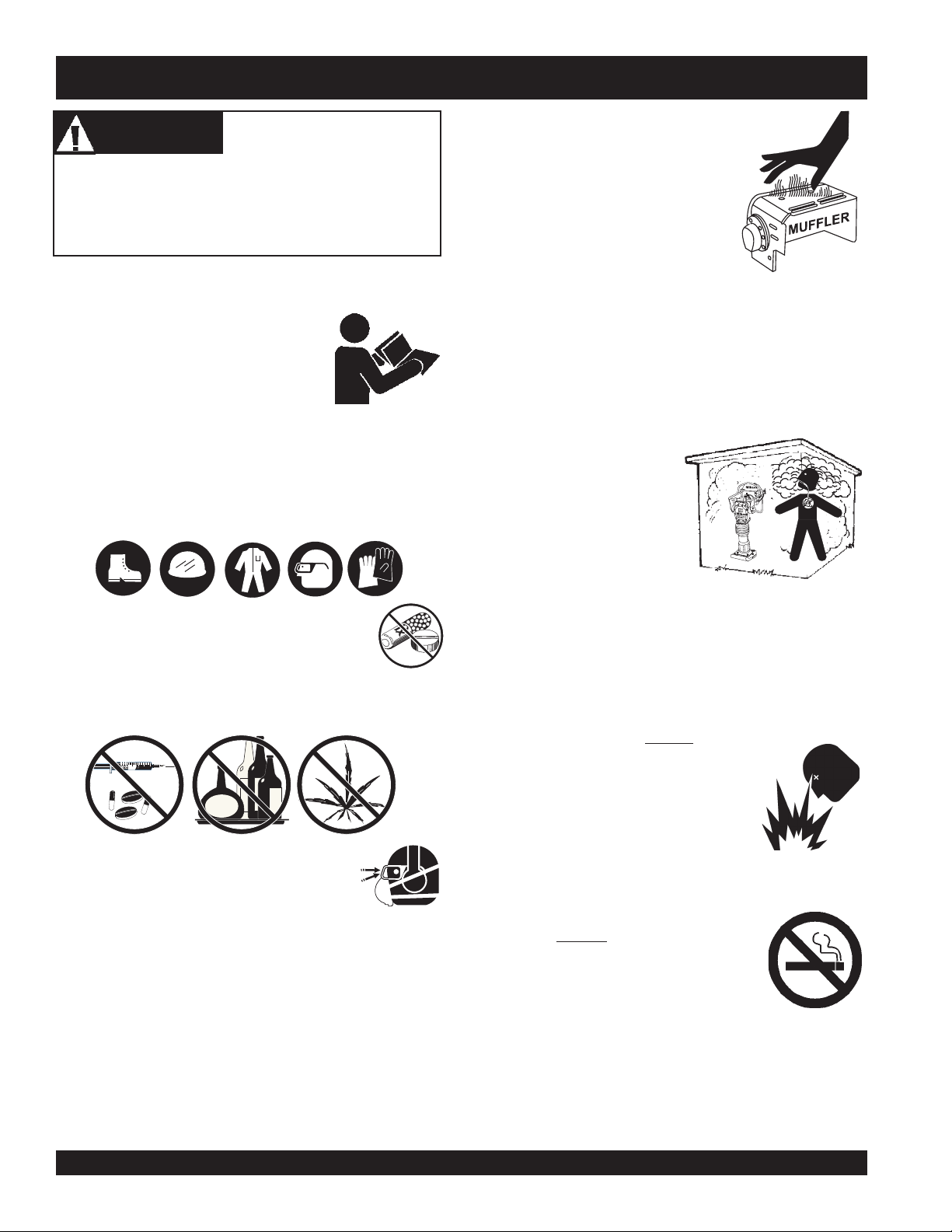
NEVER touch the hot exhaust
manifold, muffler or cylinder. Allow
these parts to cool before servicing
engine or rammer.
The following safety guidelines should always be used when
operating the MT-86D2 Tamping Rammer:
GENERAL SAFETY
■
DO NOT operate or service this
equipment before reading this entire
manual.
■
This equipment should not be operated by persons under
18 years of age.
■
NEVER operate this equipment without proper protective
clothing, shatterproof glasses, steel-toed boots and other
protective devices required by the job.
■
NEVER operate this equipment when not
feeling well due to fatigue, illness or taking
medicine.
■
NEVER operate this equipment under the influence of
drugs
or
alcohol
.
■
High Temperatures – Allow the engine to cool before
adding fuel or performing service and maintenance
functions. Contact with
burns.
■
The engine section of this rammer requires an adequate
free flow of cooling air.
any enclosed or narrow
area where free flow of the
air is restricted. If the air
flow is restricted it will
cause serious damage to
the rammer or engine and
may cause injury to people.
Remember the rammer's
engine gives off
carbon monoxide gas.
■
ALWAYS refuel in a well-ventilated area, away from
sparks and open flames.
■
ALWAYS use extreme caution when working with
flammable liquids. When refueling, stop the engine and
allow it to cool. DO NOT
or near the machine. Fire or explosion
could result from fuel vapors, or if fuel
is spilled on a hot engine.
hot!
NEVER
DEADLY
smoke
components can cause serious
operate the rammer in
around
■
■
ALWAYS wear proper respiratory (mask),
hearing and eye protection equipment when
operating the rammer.
■
Whenever necessary, replace nameplate, operation and
safety decals when they become difficult read.
■
Manufacturer does not assume responsibility for any
accident due to equipment modifications.
■
NEVER use accessories or attachments, which are not
recommended by Multiquip for this equipment. Damage
to the equipment and/or injury to user may result.
PAGE 8 — MT-86D2 TAMPING RAMMER — OPERATION AND PARTS MANUAL — REV. #3 (06/18/07)
■
■
■
■
NEVER operate the rammer in an
explosive atmosphere or near
combustible materials. An explosion or fire could result
causing severe
DO NOT
machine. Fire or explosion could result
from fuel vapors, or if fuel is spilled on a
hot engine.
Topping-off to filler port is dangerous, as it tends to spill
fuel.
Stop the engine when leaving the rammer unattended.
Maintain this equipment in a safe operating condition at
all times.
bodily harm or even death.
smoke
around or near the
Page 9

MT-86D2 TAMPING RAMMER — RULES FOR SAFE OPERATION
■
ALWAYS stop the engine before servicing, adding fuel and
oil.
■
NEVER run engine without air filter. Severe engine may
occur.
■
ALWAYS service air cleaner frequently to prevent carburetor
malfunction.
■
ALWAYS check the machine for loosened threads or bolts
before starting.
■
ALWAYS be sure the operator is familiar with proper safety
precautions and operations techniques before using rammer.
■
ALWAYS store equipment properly when it is not being used.
Equipment should be stored in a clean, dry location out of
the reach of children.
■
DO NOT operate this equipment unless all guards and
safety devices are attached and in place.
■
CAUTION must be exercised while servicing this equipment.
Rotating and moving parts can cause injury if contacted.
■
Keep all
from the equipment at all times.
■
Unauthorized equipment modifications will void all
warranties.
■
NEVER pour or spray water over the engine.
■
Test the engine ON
purpose of this switch is to shut down the engine of the
rammer.
■
Refer to the
technical questions or information recommended by
Multiquip for this equipment.
TRANSPORTING
inexperienced
and
unauthorized
/OFF
switch before operating. The
Yanmar Engine Owner's Manual
people away
for engine
MAINTENANCE
■
■
■
■
■
■
EMERGENCIES
■
ALWAYS know the location of the nearest
extinguisher
■
In emergencies
the nearest phone or
site
nearest
department
in the case of an emergency.
NEVER lubricate components or attempt service on a
running rammer.
ALWAYS allow the rammer a proper amount of time to
cool before servicing.
Keep the rammer in proper running condition.
Fix damage to the rammer immediately and always
replace broken parts.
Dispose of hazardous waste properly. Examples of
potentially hazardous waste are used motor oil, fuel
and fuel filters.
DO NOT use food or plastic containers to dispose of
hazardous waste.
fire
and first aid kit.
always
know the location of
keep a phone on the job
. Also know the phone numbers of the
ambulance, doctor
. This information will be invaluable
and
fire
■
ALWAYS shutdown engine before transporting.
■
Tighten fuel tank cap securely and close fuel cock to
prevent fuel from spilling.
■
Drain fuel when transporting rammer over long distances
or bad roads.
■
When placing the rammer inside a truck-bed for transport,
always tie-down the rammer
MT-86D2 TAMPING RAMMER— OPERATION AND PARTS MANUAL — REV. #3 (06/18/07) — PAGE 9
Page 10
MT-86D2 TAMPING RAMMER — OPERATION AND SAFETY DECALS
PAGE 10 — MT-86D2 TAMPING RAMMER — OPERATION AND PARTS MANUAL — REV. #3 (06/18/07)
Page 11

MT-86D2 TAMPING RAMMER — GENERAL INFORMATION
Definition of Tamping Rammer
The Mikasa MT-86D2 tamping rammer is a powerful compacting
tool capable of applying a tremendous force in consecutive
impacts to a soil surface. Its applications include soil compacting
for road, embankments and reservoirs as well as backfilling for
gas pipelines, water pipelines and cable installation work.
The impact force of the MT-86D2 levels and uniformly compacts
voids between soil particles to increase dry density.
Circular motion is converted to create impact force. The MT-86D2
tamping rammer develops a powerful compacting force at the
foot of the rammer. To maintain optimum performance, proper
operation and service are essential.
Construction of Tamping Rammer
The Mikasa MT-86D2 Tamping Rammer is equipped with Yanmar
diesel engine. Transmission of the power takes place by
increasing the engine speed to engage the centrifugal clutch.
Rammer Gearbox and Spring Cylinder
The Mikasa MT-86D2 uses an oil bath lubrication system. Always
check the oil level through the oil level sight glass at the rear of
the tamper foot.
Controls
Before starting the MT-86D2 Tamping Rammer, identify and
understand the function of the controls.
MT-86D2 TAMPING RAMMER— OPERATION AND PARTS MANUAL — REV. #3 (06/18/07) — PAGE 11
Page 12
MT-86D2 TAMPING RAMMER — SPECIFICATIONS
LEDOM2D68-TM
thgieHllarevO)mm060,1(.ni7.14
htdiWllarevO)mm014(ni1.61
htgneLrevO)mm027(ni3.82
snoitacificepSremmaR2D68-TM.1elbaTsnoitacificepSremmaR2D68-TM.1elbaT
snoitacificepSremmaR2D68-TM.1elbaTsnoitacificepSremmaR2D68-TM.1elbaT
snoitacificepSremmaR2D68-TM.1elbaT
eziSeohS)mm033(.n
etunim/swolB007
ecroFtcapmI)wolb/gk0002(wolb/.sbl004,4
hctulClagufirtneCcitamotuA
thgieWgnitarepO)gk29(.s
LEDOMECSRE3M9FL6V84LramnaY
epyTenignEleseiDekortS4delooC-riA
tnemecalpsiDnotsiP)cc912(.ni.uc3.31
pSdenrevoG.xaMmpr003,3
metsySgnilooCdelooC-riA
daoLoN,dee
i31
bl302
snoitacificepSenignE6V84-LramnaY.2elbaT
metsySnoitacirbuL
leuFleuFleseiDevitomotuA
metsySgnitratSretratSlioceR
Specifications are general and are subject to change without notice. If
NOTE
PAGE 12 — MT-86D2 TAMPING RAMMER — OPERATION AND PARTS MANUAL — REV. #3 (06/18/07)
exact measurements are required, equipment should be weighed and
measured.
IPAliOgnitacirbubuLenignEleseiD
edarG"DC"ro"CC"noitacifissalC
Page 13

MT-86D2 TAMPING RAMMER — CONTROLS AND COMPONENTS
Figure 1. MT-86D2 Tamping Rammer
Figure 1 shows the location of the controls and components
for the MT-86D2 Tamping Rammer. The functions of each
control is described below:
1. Fuel Tank/Cap – Remove this cap to add diesel fuel.
Use high grade automotive diesel fuel only.
2. Throttle Lever – Controls engine speed and the tamping
action of the rammer.
3. Engine Oil Dipstick – Indicates the level of the engine oil
Use CC class or higer grade motor oil.
4. Oil filter – Prevents dirt and other debris from entering the
engine.
5. Oil Bath Fill Plug – Open this plug to add oil to the oil
bath reservoir.
6. Oil Level Sight Glass – Indicates the level of oil in the oil
bath reservoir.
7. Drain Valve – Open this valve to remove oil from the
bellows.
8. Foot– Laminated wood with tempered steel plate for
superior shock absorption.
9. Muffler– Used to reduce noise and emissions.
10. Engine Air Cleaner – Prevents dirt and other debris
from entering the engine.
11. Decompression Lever – Use in the starting of the
engine. Press lever to engage. After engine starts lever
will return to original position.
12. Fuel Filter – Located inside fuel tank. Prevents dirt and
debris from entering fuel system.
13. Recoil Starting Handle – Used when starting the engine.
Pull starter handle sharply and quickly, then return
starter handle to starter case before releasing.
14. Handle – To operate rammer
firmly on both sides.
15. Bellows – Reservoir for oil bath.
GRIP
handle assembly
MT-86D2 TAMPING RAMMER— OPERATION AND PARTS MANUAL — REV. #3 (06/18/07) — PAGE 13
Page 14

MT-86D2 TAMPING RAMMER — BASIC ENGINE
Figure 2. Engine Controls and Components
The engine shown above is a
The engine must be checked for proper lubrication and filled
with fuel prior to operation. Refer to the manufacturer’s engine
manual for instructions and details of operation and servicing.
Each component is described below:
1. Fuel Filler Cap – Remove this cap to add unleaded
gasoline to the fuel tank. Make sure cap is tightened
securely. DO NOT over fill.
YANMAR L48V6
engine (Figure 2).
6. Recoil Starter– Manual-starting method. Pull the starter
grip until resistance is felt, then pull briskly and smoothly.
7. Oil Filler Cap / Dipstick – Remove this cap to add oil to the
engine crankcase. Read dipstick to determine if oil level is
low. DO NOT over fill.
NOTE
CAUTION - Fueling The Engine
Adding fuel to the tank should be done only
when the engine is stopped and has had an
opportunity to cool down. In the event of a fuel
spill, DO NOT attempt to start the engine until
the fuel residue has been completely wiped
up, and the area surrounding the engine is dry.
2. Fuel Tank – Capacity is 3.5 quarts (3.31 liters) of diesel
fuel.
3. Air Cleaner – Prevents dirt and other debris from entering
the fuel system. Remove wing-nut on top of air filter
cannister to gain access to filter element.
4. Muffler – Used to reduce noise and emissions.
5. Recoil Starting Handle (pull rope) – Type of engine
starting method.
8. Oil Drain Plug – Unscrew plug to drain oil from engine
crankcase. Dispose of oil in a safe manner.
9. Decompression Lever– Press down before starting
engine. To prevent damage to engine, DO NOT use for any
other purpose.
CAUTION - Burn Hazard
Engine components can generate extreme heat.
To prevent burns, DO NOT touch these areas
while the engine is running or immediately after
operating. NEVER operate the engine with the
muffler removed.
10. Fuel Cock– Controls the flow of diesel fuel to the carburetor.
Must be in the ON position when starting and running the
engine.
Operating the engine without
an air filter, with a damaged
air filter, or a filter in need of
replacement will allow dirt to
enter the engine, causing
rapid engine wear.
PAGE 14 — MT-86D2 TAMPING RAMMER — OPERATION AND PARTS MANUAL — REV. #3 (06/18/07)
Page 15
MT-86D2 TAMPING RAMMER — INITIAL START-UP
This section is intended to assist the operator with the initial
start-up of the MT-86D2 Tamping Rammer. It extremely important
that this section be read carefully before attempting to operate
the rammer.
DO NOT use your rammer until this section is thoroughly
understood.
CAUTICAUTI
CAUTION
CAUTICAUTI
Failure to understand the operation of
the MT-76D2Tamping Rammer could
result in severe damage to the rammer
or cause personal injury.
Rammer Gearbox and Spring Cylinder
This unit uses an oil bath lubrication system. Check oil level
through oil level sight glass at rear of tamper foot. If oil is not
visible, add #10W-30 motor oil. Oil bath contains approx. 1.7 pt.
(800cc).
Engine
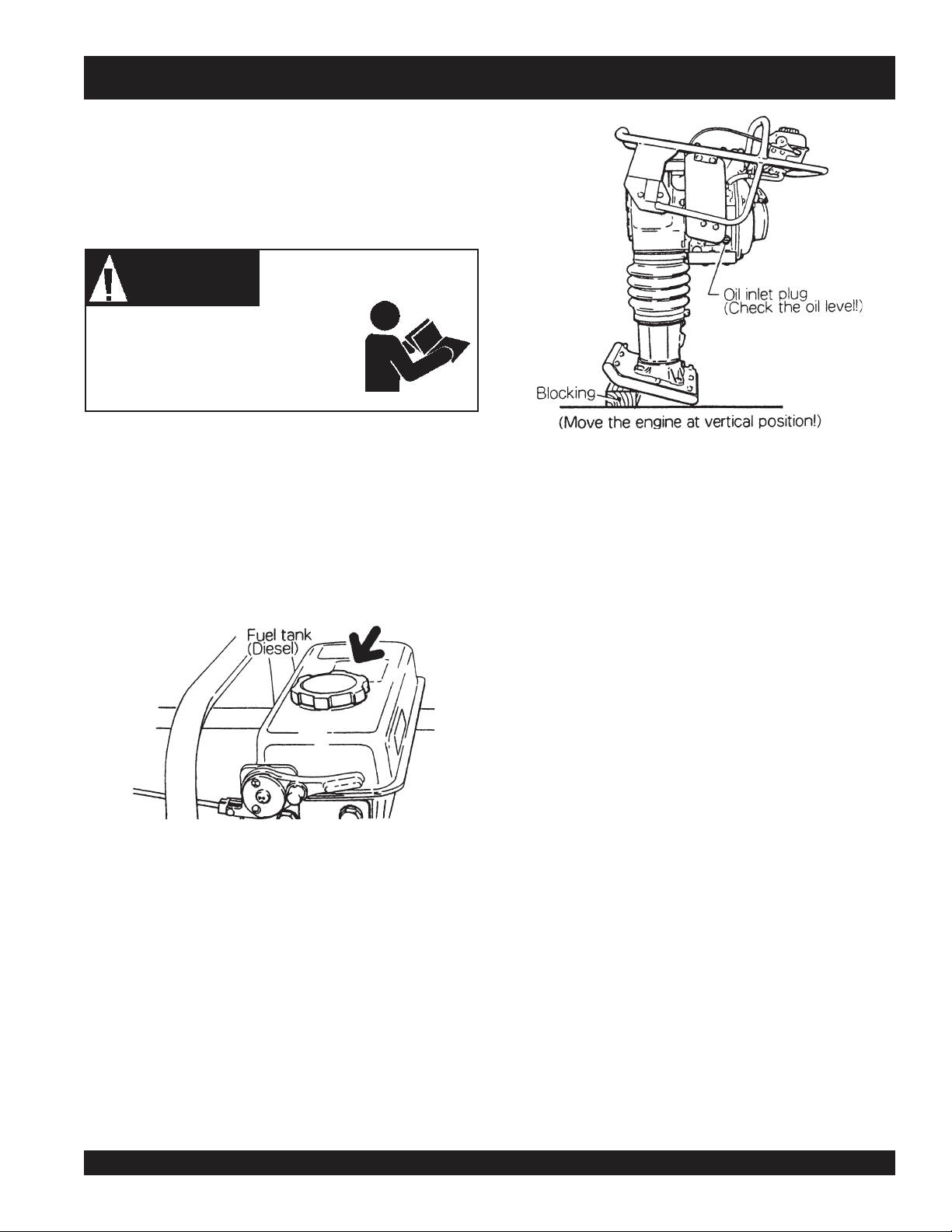
1. Fill the fuel tank with automobile diesel fuel (See Figure 3).
Read Manual
INSPECTION
1. Check all nuts, bolts and fasteners for tightness. Retighten
as necessary.
2. Clean dirt from the recoil starter and foot. Wipe entire unit
clean before operating.
3. Replace any missing or damaged Safety/Operation decals.
Figure 4. Oil Level
Figure 3. Fuel Tank
2. For checking the oil level, move the engine to vertical
position and check that the oil is level with the oil inlet (about
700cc). See Figure 4.
MT-86D2 TAMPING RAMMER— OPERATION AND PARTS MANUAL — REV. #3 (06/18/07) — PAGE 15
Page 16
MT-86D2 TAMPING RAMMER — INITIAL START-UP
4. Starting
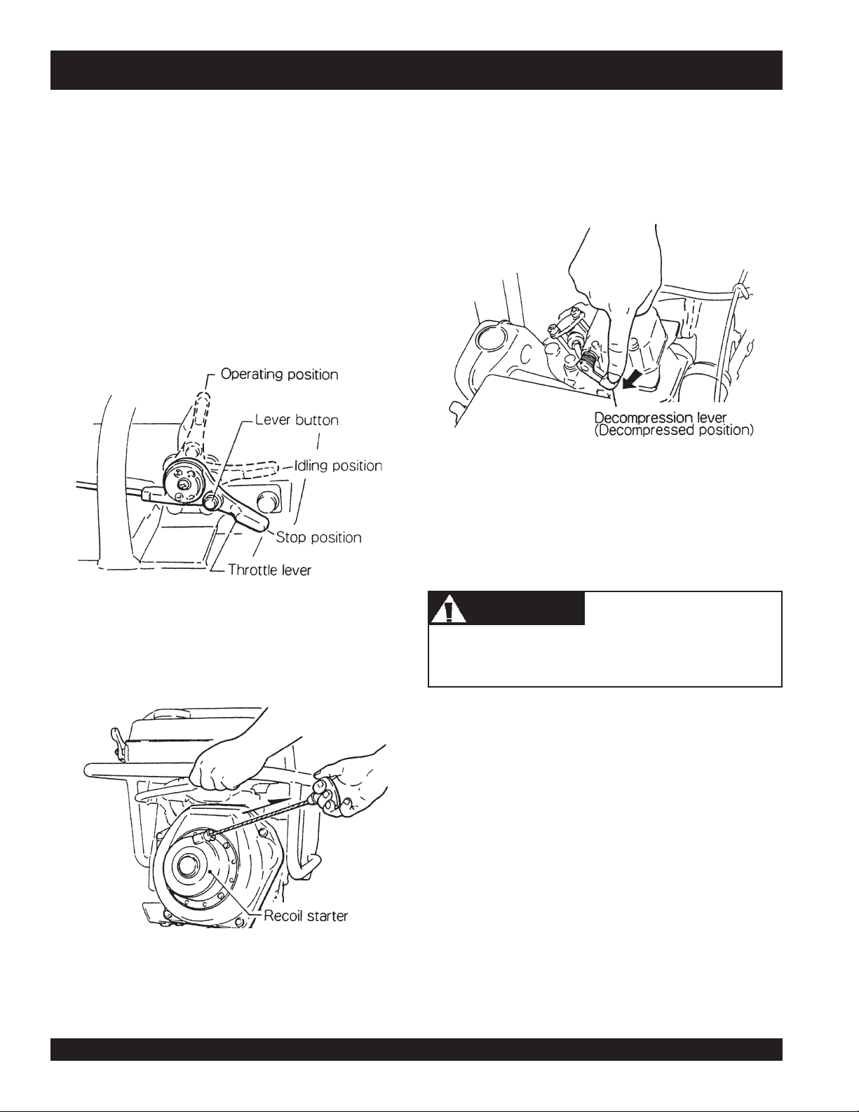
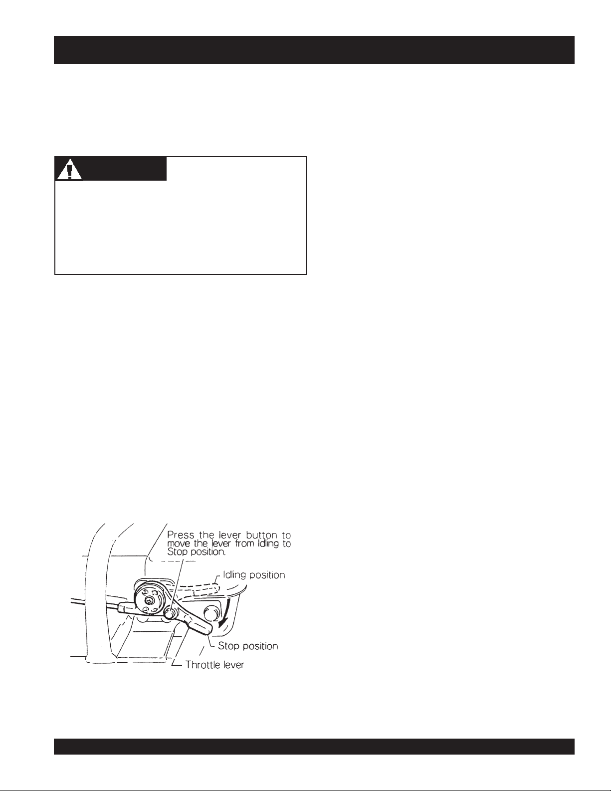
1. Move the throttle lever to IDLE position. (See Figure 5).
Throttle lever is used only at three (STOP, IDLE &
OPERATION) positions. When moving the lever from stop
to idle position, press button on lever at same time it is
moved.
In cold weather, the engine should be started at operating
position or between the idle and operation position of the
throttle lever. Use caution as higher engine RPM may
engage clutch, when engine starts. Return throttle lever
from starting position to idle position when engine starts.
3. Press the decompression lever to release decompression.
The decompression lever will return automatically when
the recoil starter is pulled. (See Figure 7).
Figure 7. Decrompression Lever
4. Return the recoil starter, and pull the handle sharply and
quickly. Warm up the engine by running at low speed for
three to five minutes, while checking for fuel leakage or
abnormal sounds.
Figure 5. Throttle Lever
2. Grip the recoil starter handle and pull it until you feel a
slight resistance. (See Figure 6).
Do not pull the starter rope all the way to the end and do not
let the starter rope snap back as damage may result.
CAUTICAUTI
CAUTION
CAUTICAUTI
Figure 6. Recoil Starter
PAGE 16 — MT-86D2 TAMPING RAMMER — OPERATION AND PARTS MANUAL — REV. #3 (06/18/07)
Page 17
MT-86D2 TAMPING RAMMER — OPERATION
Operation
1. Move the throttle lever quickly from the IDLE to OPERATION
position to start tamping action. DO NOT move the throttle
lever slowly as this may cause damage to the clutch or
spring box.
CAUTICAUTI
CAUTION
CAUTICAUTI
The tamping rammer is designed to tamp the ground 700
times per minute at an engine speed of 3,300 rpm.
Increasing the engine speed above the recommended rpm
will not increase the rammer effectiveness. Impact will
actually decrease because a resonance is created rather
than a tamping effect, and damage to the unit can result.
2. The rammer can be warmed by quickly moving the throttle
lever from the OPERATION to the IDLE position several
times until the rammer operates smoothly.
3. The tamping rammer is designed to travel forward while
tamping. To increase travel speed, pull back slightly on the
handle so that the rear of the foot contacts the soil first.
4. To stop tamping, quickly move the throttle lever from the
OPERATION to IDLE position. Do not move the lever slowly
as irregular action and damage may result.
Stopping the Engine
1. Move throttle lever quickly from idle to STOP while pressing
the throttle lever button. Run the engine for three minutes
at idle speed to allow for proper cool down. Following the
above procedures will prevent improper cylinder lubrication
caused by a overheated engine. See Figure 8.
Figure 8. Stopping the Engine
MT-86D2 TAMPING RAMMER— OPERATION AND PARTS MANUAL — REV. #3 (06/18/07) — PAGE 17
Page 18
MT-86D2 TAMPING RAMMER — MAINTENANCE
MAINTENANCE
Perform the scheduled maintenance procedures as indicated:
Daily
Replacement of Lubricant (ENGINE)
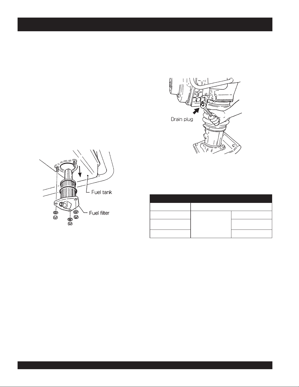
1. While the engine is still warm, remove the drain plug. For
quick discharging, it is advisable to take off the oil gauge.
Replace drain plug and refill engine crankcase. See Figure
■
Thoroughly remove dirt and oil from the engine and control
10.
area.
■
Clean or replaces air cleaner as necessary.
■
Check and retighten all fasteners as necessary.
■
Check spring box and bellows for oil leaks. Repair as
needed.
■
Remove element from pre-cleaner at the top of crankcase
(body side) and clean it by air.
Weekly (every 50 hours)
■
Remove the fuel filter cap and inspect for dirt in the fuel
tank. See Figure 9.
2. Refer to Table 3 for oil types. Inferior quality engine oil and/
or lack of oil may cause engine trouble or shorten engine
life.
Figure 10. Replacement of Lubricant
Figure 9. Removing Fuel Filter Cap
Replacement of Lubricant (Body)
■
Remove the drain plug at the rear of tamper foot and drain
the dirty oil. Refill with clean oil to the middle of the sight
glass. Oil bath contains approx. 1.7 pt. (800 cc).
INITIAL OIL CHANGE:
After 50 hours of operation.
SECOND OIL CHANGE AND/OR LATER
Every 200 hours of operation.
edarGliOrotoM3elbaT
erutarepmeTliOrotoMfoedarG
evobAdnaF°86
F°86+otF°41+
F°41+woleB03-W01EAS
edargrehgihrossalCCC
Engine Oil Replacement Interval
INITIAL OIL CHANGE:
After 20 hours of operation.
SECOND OIL CHANGE AND/OR LATER:
Every 100 hours of operation.
03EAS
02EAS
PAGE 18 — MT-86D2 TAMPING RAMMER — OPERATION AND PARTS MANUAL — REV. #3 (06/18/07)
Page 19

MT-86D2 TAMPING RAMMER — MAINTENANCE
Cleaning the Air Cleaner
Clean the Air Cleaner every 200-300 hours. See Figure 11.
■
Remove element from pre-cleaner at the top of crankcase
(body side).
■
Wash the element (outside) in detergent solution.
■
Shake out excess moisture and dry the element.
■
Clean inside element with air from the inside of element.
Fuel Pipe & Oil Pipe
■
■
Transportation
Maintain upright position of rammer at all times. Transport rammer
in upright position. If machine must be laid down for
transportation, drain the diesel fuel first and lay machine with
muffler side down. See Figure 13.
Check fuel line regularly for damage, paying attention to
clamps to assure a tight fit.
Replace fuel line every two years to maintain original
performance.
Figure 11. Air Cleaner
Cleaning the Oil Filter
Drain oil filter every 100 hours of operation. Replace the oil filter
every 1,000 hours of operation. See Figure 12.
The fuel filter is installed at the bottom of fuel tank. Should the
rammer be laid on its side, dirt from the fuel filter may contaminate
the injection nozzle, causing damage to the fuel pump.
Storage
■
When storing the rammer for long periods of time, thoroughly
drain all fuel from line.
■
Clean exterior of rammer with an oil moistened cloth. Cover
Figure 12. Oil Filter
and store in a clean, dry place.
Figure 13. Transporting Rammer
MT-86D2 TAMPING RAMMER— OPERATION AND PARTS MANUAL — REV. #3 (06/18/07) — PAGE 19
Page 20

MT-86D2 TAMPING RAMMER — TROUBLESHOOTING
GNITOOHSELBUORTENIGNE.4ELBAT
MOTPMYSMELBORPELBISSOPNOITULOS
?noitisop"POTS"nisirevellortnocdeepS
?pmupnoitcejnignihcaerleufoN.metsysleuferitnekcehC.leufddA
eufevitcefeD.pmupleufecalpeR
sitratsrotratstonlliwenignE
nacenignehguohtla,deyaled
.revodenruteb
serpliO.erusserplioenignekcehC
lliwenigneserutarepmetwoltA
.tratston
epmetwol
?pmupl
?deggolcretlifleuF.knatnaelcdnaretlifleufecalpeR
?enilylppusleufytluaF.enille
?wolootnoisserpmoC
?yltcerrocgnikrowtonrotcejnileuF
?wolooterus
dedeecxetimilerutarepmetgnitratswoL
otecnatsiseretauqedanisahsetarapesleuF
?serutar
.leuf
ufriaperroecalpeR
.launamriaperenignerepriaper
.launamriaperenigne
.ytisocsivlioreporp
rutsileufehtfI.)pmup
.noitisop"TRATS"otrevellortnocdeepsteS
rotsujdA.sevlavdnarednilyc,notsipkcehC
htiwecnadroccanirotcejniecalperroriapeR
dnasnoitcurtsnignitratsdlochtiwylpmoC
segremeleuf)dibrutton(raelcrehtehwkcehC
noitcejnimorfhcated(enilleufehtmorf
mraw,detarapesrodib
leufetelpmocehtniardroenigneehtpu
leseidedargretniwhtiwleufeR.metsysylppus
ihtootlioenignE
?kc
E
.ffodehctiwssiretrats
.noitarepolamron
.deeps
oL
.ekoms
sanoosspotstubserifenign
irudflestiybspotsenignE
gn
tuo,rewopenignewoL
dnatup
es
dnatuptuorewopenignew
tsuahxekcalb,deepswol
?dekcolbretlifleuF.retlifleufecalpeR
?dekcolbylppusleuF.metsysleuferitneehtkcehC
?ytpmeknatleuF.leufddA
?dekcolbretlifleuF.retlifleufecalpeR
?ytpmeknatleuF.leufleseid2.oNhtiwlliF
?deggolcretlifleuF.retlifleufecalpeR
?etauqedanisignitnevknatleuF.detnevyletauqedasiknattahterusnE
niniamertonseodrevellortnocdeepS
?noitisopdetcel
?llufootlevellioenignE?levellioenignetcerroC
?dekcolbretlifriA.retlifriaecalperronaelC
?secnaraelcevlavtcerrocnI.noitaci
?rotcejnitanoitcnuflaM.launamenigneeeS
.tnemnorivneretniwrof
ficepsenignerepsevlavtsujdA
liofoepyttcerrochtiwesacknarcenignellifeR
.noitcaevitcerrocroflaunamenigneeeS
PAGE 20 — MT-86D2 TAMPING RAMMER — OPERATION AND PARTS MANUAL — REV. #3 (06/18/07)
Page 21

MT-86D2 TAMPING RAMMER — TROUBLESHOOTING
GNITOOHSELBUORTREMMAR.5ELBAT
MOTPMYS MELBORPELBISSOP NOITULOS
?tesyltcerrocnisi
?ssecxeniliO .leveltcerrocotgnirB.liossecxeniarD
ediutilpmatubsetatorenignE
.ekirtstonseodromrofinuton
?spilshctulC .hctulctsujdaroecalpeR
?eruliaFgnirpS .gnirpslairpsecalpeR
revelelttorhtfodeepsgnitarepO
?reporpmienignefodeepS .gnittesMPRgnitarepotcerrocotdeepsenignetsujdA
.noitisoptcerrocotrevelelttorhtteS
MT-86D2 TAMPING RAMMER— OPERATION AND PARTS MANUAL — REV. #3 (06/18/07) — PAGE 21
Page 22

MT-86D2 TAMPING RAMMER — EXPLANATION OF PARTS SECTION
The following section explains the different symbols and remarks
used in the Parts section of this manual. Use the help numbers
found on the back page of the manual if there are any questions.
The contents and part numbers listed in the parts section are
subject to change
guarantee the availability of the parts listed.
Sample Parts List:
NO. PART NO. PART NAME QTY. REMARKS
1 12345 BOLT ....................... 1 .... INCLUDES ITEMS W/
2
*
2*12347 WASHER, 3/8 IN. .... 1 ....
3 12348 HOSE .................... A/R .. MAKE LOCALLY
4 12349 BEARING ................ 1 .... S/N 2345B AND ABOVE
NO. Column
Unique Symbols - All items with same unique symbol
, #, +, %, or >) in the number column belong to the same
(
*
assembly or kit, which is indicated by a note in the “Remarks”
column.
Duplicate Item Numbers - Duplicate numbers indicate
multiple part numbers are in effect for the same general item,
such as different size saw blade guards in use or a part that
has been updated on newer versions of the same machine.
NOTE
without notice
WASHER, 1/4 IN. ...........
When ordering a part that has more
than one item number listed, check
the remarks column for help in
determining the proper part to order.
. Multiquip does not
NOT SOLD SEPARATELY
MQ-45T ONLY
QTY. Column
Numbers Used - Item quantity can be indicated by a number,
a blank entry, or A/R.
A/R (As Required) is generally used for hoses or other parts
that are sold in bulk and cut to length.
A blank entry generally indicates that the item is not sold
separately. Other entries will be clarified in the “Remarks”
Column.
REMARKS Column
Some of the most common notes found in the “Remarks”
*
Column are listed below. Other additional notes needed to
describe the item can also be shown.
Assembly/Kit
symbol will be included when this item is purchased.
Indicated by:
“INCLUDES ITEMS W/(unique symbol)”
Serial Number Break
range where a particular part is used.
Indicated by:
“S/N XXXXX AND BELOW”
“S/N XXXX AND ABOVE”
“S/N XXXX TO S/N XXX”
Specific Model Number Use
only with the specific model number or model number variant
listed. It can also be used to show a part is NOT used on a
specific model or model number variant.
Indicated by:
“XXXXX ONLY”
“NOT USED ON XXXX”
REMARKS
- All items on the parts list with the same unique
- Used to list an effective serial number
- Indicates that the part is used
PART NO. Column
Numbers Used - Part numbers can be indicated by a number,
a blank entry, or TBD.
TBD (To Be Determined) is generally used to show a part that
has not been assigned a formal part number at time of
publication.
A blank entry generally indicates that the item is not sold
separately or is not sold by Multiquip. Other entries will be
clarified in the “Remarks” Column.
PAGE 22 — MT-86D2 TAMPING RAMMER — OPERATION AND PARTS MANUAL — REV. #3 (06/18/07)
“Make/Obtain Locally”
purchased at any hardware shop or made out of available
items. Examples include battery cables, shims, and certain
washers and nuts.
“Not Sold Separately”
purchased as a separate item and is either part of an
assembly/kit that can be purchased, or is not available for
sale through Multiquip.
- Indicates that the part can be
- Indicates that an item cannot be
Page 23

MT-86D2 TAMPING RAMMER — SUGGESTED SPARE PARTS
MT-86D2 RAMMER with Yanmar L48V6 Engine
1-3 UNITS
1 .... 956100057 ...........THROTTLE WIRE
3 .... 371010060 ...........ELEMENT ASSY
2 .... 954406010 ...........STRAINER, FUEL TANK
3 .... 18325455120 .......STRAINER ASSY, FUEL
1 .... 0430430015 .........CAP, FUEL TANK
2 .... 11425035110 .......STRAINER, OIL LUB.
1 .... 16026076630 .......ROPE, RECOIL STARTER
Part numbers on this Suggested
NOTE
Spare Parts List may supersede/
replace the P/N shown in the text
pages of this book.
MT-86D2 TAMPING RAMMER— OPERATION AND PARTS MANUAL — REV. #3 (06/18/07) — PAGE 23
Page 24

MT-86D2 TAMPING RAMMER — NAME PLATE AND DECALS
NAME PLATE AND DECALS
PAGE 24 — MT-86D2 TAMPING RAMMER — OPERATION AND PARTS MANUAL — REV. #3 (06/18/07)
Page 25

MT-86D2 TAMPING RAMMER — NAMEPLATE AND DECALS
NAME PLATE AND DECALS
NO. PART NO. PART NAME QTY. REMARKS
1
*
2
*
3
*
4
*
5
*
6 NAMEPLATE ...........................................1 ........ CONTACT MQ PARTS DEPT.
7
*
8
*
9 DCL86D/76D DECAL KIT, MT-86D/MT-76D ...................1 ........ INCLUDES ITEMS W/
10 920209100 DECAL: CAUTION 1
11 920109360 DECAL: DO NOT LAY DOWN 1
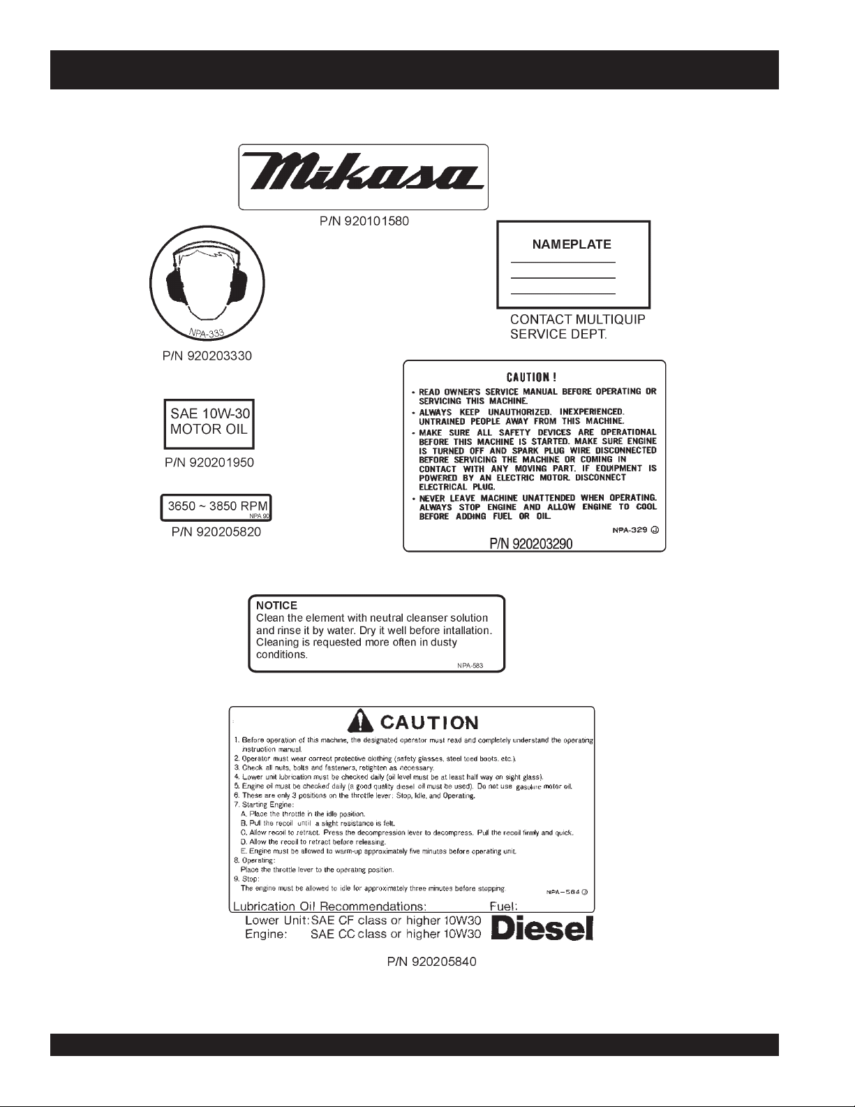
920101580 DECAL: MIKASA MARK 1
920205840 DECAL: FUEL DIESEL ............................1 ........ NPA-584
920203330 DECAL: EAR PROTECTION .................... 1 ........ NPA-333
920205820 DECAL ENGINE R.P.M 3100-3300 1
920203290 DECAL: READ OWNER'S MANUAL ........ 1 ........ NPA-329
920201950 DECAL: MOTOR OIL 1
920205830 DECAL, AIR CLEANER ...........................1 ........ NPA-583
*
MT-86D — NAME PLATES AND DECALS
MT-86D2 TAMPING RAMMER— OPERATION AND PARTS MANUAL — REV. #3 (06/18/07) — PAGE 25
Page 26

MT-86D2 TAMPING RAMMER — CRANKCASE AND ENGINE ASSY.
CRANKCASE AND ENGINE ASSY.
PAGE 26 — MT-86D2 TAMPING RAMMER — OPERATION AND PARTS MANUAL — REV. #3 (06/18/07)
Page 27

MT-86D2 TAMPING RAMMER — CRANKCASE AND ENGINE ASSY.
CRANKCASE AND ENGINE ASSY.
NO. PART NO. PART NAME QTY. REMARKS
1 372113340 CRANKCASE 1
2 372335090 CRANK GEAR 1
4 040006307 BEARING 6307 1
5 040006205 BEARING 6205 1
6 952400690 WASHER 9 X 35 X 4.5 1
7 002219825 BOLT 8X25H, SW ........................... 1 .......... REPLACES 002210825
8 372447660 BEARING COVER 1
9 050300500 O-RING S-50 1
10 080100600 STOP RING R-60 2
11 001210610 BOLT 6X10H 1
12 031106100 WASHER M6 1
13 301300530 CONNECTING ROD 1
14 040006305 BEARING 6305 1
15 080100620 STOP RING R-62 1
16 952400690 WASHER 9304 1
17 002210825 BOLT 8X25H, SW ........................... 1 .......... REPLACES 002210825
19 372447670 PACKING, FRONT COVER 1
20 002200620 BOLT 6X20H, SW 9
22 372447680 PINION 1
23 040006205 BEARING 6205 1
24 080200350 STOP RING S-35 1
25 371449600 SPACER .......................................... 1 .......... REPLACES 371335280
26 060404010 OIL SEAL TC-40528 1
27 050101000 O-RING G-100 1
28 371447640 CLUTCH DRUM 1
29 952405610 KEY 5X5X19R 1
30 952405490 LOCK WASHER 1
31 002210820 BOLT 8X20H, SW 1
32 041006007 BEARING 6007Z 1
34 22512040120 KEY 4X12 1
35 371447632 CLUTCH ASSY. .............................. 1 .......... INCLS. ALL ITEMS W/
35-1*943020060 CLUTCH SHOE (4) 1
35-2*943050050 CLUTCH BOSS 1
35-3*943060100 CLUTCH GUIDE (A) 1
35-4*943060020 CLUTCH GUIDE (B) 1
35-5*943030021 CLUTCH SPRING 2
36 301010210 LOCK WASHER, CLUTCH 1
37 371448260 SPACER 15X24X4 1
38 022910170 NUT M12 1
41 371448220 PACKING, AIR CLEANER 1
42 371213392 AIR CLEANER ASSY ..................... 1 .......... INCLUDES ITEMS W/# REPLACES 371213390
42A# 371010060 ELEMENT ASSY 1
42B# 371010030 BODY ASSY 1
42C# 371010042 BACK PLATE 1
42D# 371010050 SEAT, AIR CLEANER 1
42E# 371010070 BOLT ASSY. 1
*
MT-86D2 TAMPING RAMMER— OPERATION AND PARTS MANUAL — REV. #3 (06/18/07) — PAGE 27
Page 28

MT-86D2 TAMPING RAMMER — CRANKCASE AND ENGINE ASSY.
CRANKCASE AND ENGINE ASSY.
PAGE 28 — MT-86D2 TAMPING RAMMER — OPERATION AND PARTS MANUAL — REV. #3 (06/18/07)
Page 29

MT-86D2 TAMPING RAMMER — CRANKCASE AND ENGINE ASSY.
CRANKCASE AND ENGINE ASSY.
NO. PART NO. PART NAME QTY. REMARKS
43 002200820 BOLT 8X20H, SW 4
44 371335110 INTAKE PIPE 1
45 371000010 HOSE BAND (B) 1
46 371000020 HOSE BAND (B) 1
47 371335270 INTAKE FLANGE 1
48 11428412200 GASKET, AIR INTAKE 1
49 001200652 BOLT 6X60 2
50 030206150 WASHER SW M6 2
57 26226100452 STUD M10X20 PLATED 2
58 020310080 NUT M10 2
59 030210250 WASHER SW M10 2
60 002211050 BOLT 10X50H, SW 2
65 372213560 FRONT COVER MQ 1
71 914410025 ENGINE ASSY L48V6 1
72 371335100 UNDER PROTECTOR 1
73 001211040 BOLT 10X40 H 2
74 020310080 NUT M10 2
75 030210250 WASHER, LOCK M10 2
76 031110160 WASHER, FLAT M10 1
77 371448021 LINK PROTECTOR 1
78 001200630 BOLT 6X30 1
79 001200635 BOLT 6X35 1
80 030206150 WASHER SW M6 2
81 16026078700 CLAMP WIRE 2
82 11425066440 BOLT, ADJUSTING 2
83 26756060002 LOCK NUT M6 PLATED 2
160 362910060 THROTTLE LEVER ASSY 1
162 362341550 THROTTLE BODY 1
163 362910090 THROTTLE GEAR CP W/ BOLT 1
165 362455620 SLIDER 1
166 362455630 THROTTLE LEVER 1
167 050100450 O-RING G-45 1
168 050200100 O-RING P-10 1
169 031110160 WASHER, FLAT M10 3
170 032110180 CONICAL SPRING WASHER M10 2
171 096206006 SOCKET HEAD SCREW 6X6 1
172 022131008 CAP NUT M10 1
173 020410060 NUT M10 ,H=6 1
174 096208020 SOCKET HEAD SCREW 8X20 1
175 020408050 NUT M8, H=5 2
176 956100057 THROTTLE WIRE V390-510 1
177 001220620 BOLT 6X20 T 2
178 030206150 WASHER, LOCK M6 2
179 022130605 CAP NUT M6 2
MT-86D2 TAMPING RAMMER— OPERATION AND PARTS MANUAL — REV. #3 (06/18/07) — PAGE 29
Page 30

MT-86D2 TAMPING RAMMER — CYLINDER GUIDE AND FOOT ASSY.
CYLINDER GUIDE AND FOOT ASSY.
PAGE 30 — MT-86D2 TAMPING RAMMER — OPERATION AND PARTS MANUAL — REV. #3 (06/18/07)
Page 31

MT-86D2 TAMPING RAMMER — CYLINDER GUIDE AND FOOT ASSY.
CYLINDER GUIDE AND FOOT ASSY.
NO. PART NO. PART NAME QTY. REMARKS
61 652423290 PISTON PIN.................................... 1 .......... REPLACES 352423290
62 363457870 PISTON PIN PLUG 2
63 352210380 PISTON ROD 1
64 372447700 PISTON END 1
65 020118150 NUT M18, P1.5 1
66 352431430 STOPPER,UPPER 1
67 352437470 STOPPER,LOWER 1
68 372335260 MAIN SPRING 2
69 372213180 SPRING CYLINDER 1
70 372213570 FOOT PLATE 1
71 352110042 PROTECTION SLEEVE .................. 1 .......... REPLACES 352110040
73 050100950 O-RING G-95 1
74 050101100 O-RING G-110 1
75 014210020 SOCKET HEAD BOLT 10X20 T ...... 4 .......... REPLACES 001521020
76 014210035 SOCKET HEAD BOLT 10X35 T ...... 4 .......... REPLACES 001521035
77 953405270 PLUG 1/4X14 13L 2
78 953405260 PACKING 1/4(CU) 2
80 354446170 PIN 6D-8.5L 2
82 354212490 GUIDE CYLINDER(L) 1
86 354010010 BELLOWS,ORANGE 1 REPLACES 354332780
87 050931500 O-RING JAS03150 2
88-1 354910020 BELLOWS CLAMP CP ................... 2 .......... INCLS. ALL ITEMS W/
89 012710035 BOLT 10X35 H,SW ......................... 4 .......... REPLACES 002211035
90 959010150 LEVEL GAUGE,PLUG TYPE 1
91 953404670 COPPER PACKING 17X25.5X1 1
92 050201500 O-RING P-150 1
100 352910081 FOOT ASSY 330W-W/F.COVER ..... 1 .......... INCLS. ALL ITEMS W/#
103# 001611255 SUNK HEAD BOLT 12X75 H 4
104# 001611259 SUNK HEAD BOLT 12X95 H .......... 2 .......... REPLACES 001611260
105# 015110055 SUNK HEAD BOLT 10X55 H .......... 7 .......... REPLACES 001611051
106 021112140 NYLON NUT M12 ............................ 4 .......... REPLACES 022711214
107 030212300 WASHER, LOCK M12 4
108# 021110120 NYLON NUT M10 ............................ 7 .......... REPLACES 022711012
109# 030210250 WASHER, LOCK M10 7
114 352441730 SPRING SEAT 80D-1.6T 1
115*354336352 BELLOWS CLAMP (1.6T) 171D ...... 2 .......... REPLACES 354329380
116*354442340 BAND GUIDE,BELLOWS 2
117*001220840 BOLT 8X40T 2
118*020108060 NUT M8 ........................................... 2 .......... REPLACES 020308060
*
MT-86D2 TAMPING RAMMER— OPERATION AND PARTS MANUAL — REV. #3 (06/18/07) — PAGE 31
Page 32

MT-86D2 TAMPING RAMMER — TANK AND HANDLE ASSY.
TANK AND HANDLE ASSY.
PAGE 32 — MT-86D2 TAMPING RAMMER — OPERATION AND PARTS MANUAL — REV. #3 (06/18/07)
Page 33

MT-86D2 TAMPING RAMMER — TANK AND HANDLE ASSY.
TANK AND HANDLE ASSY.
NO. PART NO. PART NAME QTY. REMARKS
101 351319900 SHOCK ABSORBER 2
102-1 014210020 SOCKET HEAD BOLT 10X20T ........... 4 ............REPLACES 001521020
102-2 033121009 TOOTHED LOCK WASHER B M10 4
104 012210020 BOLT 10X20H, SW .............................. 4 ............ REPLACES 002211020
105 371118200 FUEL TANK 1
106 0430430015 FUEL TANK CAP .................................. 1 ............ REPLACES 953404650
107 954406010 STRAINER (#110) 1
108 011808015 BOLT 8X15H, SW, PW......................... 4 ............ REPLACES 002410815
109 18325455120 STRAINER ASSY, FUEL 1
110 020106050 NUT M6 ............................................... 3 ............ REPLACES 020306050
111 030206150 WASHER, LOCK M6 3
115 953405750 PACKING 10.5D-17D-2T 1
116 953405800 FLANGE PLUG PF1/8 1
201 371118190 HANDLE 1
202 371448010 SIDE PROTECTOR 1
203 011808015 BOLT 8X15H, SW, PW......................... 3 ............ REPLACES 002410815
302 953406200 PROTECTION CAP 1
303 953405740 PLASTIC CAP VC12 1
501 18366659330 PIPE, FUEL DRAIN 1
502 18325059050 PIPE, FUEL OIL 1
503 11465459070 PIPE, FUEL RETURN 1
504 11428459710 JOINT 1
505 12476659050 CLAMP 11.5 2
506 10699044660 BAND HOSE 12.5 3
507 12472259050 CLAMP 9 2
508 18325059040 PIECE 1
616 955200052 ROLLER, W/ PIN 2
616 955200053 ROLLER, W/ PIN 2
617 091005025 SCREW 5X25 4
618 031105080 WASHER, FLAT M5 4
619 022610505 FLANGE NUT M5 H 4
MT-86D2 TAMPING RAMMER— OPERATION AND PARTS MANUAL — REV. #3 (06/18/07) — PAGE 33
Page 34

CYLINDER BLOCK ASSY.
YANMAR L-48V6 ENGINE — CYLINDER BLOCK ASSY.
PAGE 34 — MT-86D2 TAMPING RAMMER — OPERATION AND PARTS MANUAL — REV. #3 (06/18/07)
Page 35

YANMAR L-48V6 ENGINE — CYLINDER BLOCK ASSY.
CYLINDER BLOCK ASSY.
NO. PART NO. PART NAME QTY. REMARKS
1 11429501050 CYLINDER BLOCK ASSY. 1
5 11439901700 STARTER COVER 1
6 26106100122 BOLT M10X 12 PLATED 2
7 24162152112 NEEDLE BEARING 1
8 26106080122 BOLT M 8X 12 PLATED 1
9 11429901200 CYLINDER HEAD BOLT A 2
10 11429901210 CYLINDER HEAD BOLT B 2
11 11429901220 CYLINDER HEAD NUT A 2
12 11429901230 CYLINDER HEAD NUT B 2
13 12495001250 WASHER 4
14 11429501330 CYLINDER HEAD GASKET ASSY. 1
20 11429901380 O- RING 1
21 11429901600 PIN 8X12 2
22 11429901800 SHIM SET 1
33 11429901830 COVER, (FO PUMP) 1
34 11425001841 GASKET 1
35 22312040080 PIN 4X8 STRAIGHT 2
36 26226060182 STUD M 6X 18 PLATED 1
37 26226060222 STUD M 6X 22 PLATED 2
38 26366060002 NUT M 6 3
39 11429901410 CRANK CASE GASKET 1
40 11428401452 DRUM CASE COVER ................................ 1 ................ INCLUDES ITEMS W/
45
45
45
48 11429935150 L.O. INLET PIPE 1
49 26106060252 BOLT M 6X 25 PLATED 14
50 26106080352 BOLT M 8X 35 PLATED 1
53 11429901690 PLUG M16 2
54 11429901760 CAP, W/LUBE OIL GAUGE ....................... 1 ................ INCLUDES ITEMS W/#
56# 11429901950 O- RING 1
57 22190160002 SEAL WASHER 16S 2
58 11429902030 RETAINER 1
59 11425002113 BALL BEARING 1
60 11429902220 OIL SEAL 1
61 16021002220 OIL SEAL 1
62 23876010000 PLUG PT 1/8, SCREW 1
11425002100 MAIN BEARING US=STD. 1
*
11425002200 BEARING US=0.25, MAIN 1
*
11425002210 BEARING US=0.50, MAIN 1
*
*
MT-86D2 TAMPING RAMMER— OPERATION AND PARTS MANUAL — REV. #3 (06/18/07) — PAGE 35
Page 36

YANMAR L-48V6 ENGINE — CYLINDER HEAD ASSY.
CYLINDER HEAD ASSY.
MT-76D — L40ADRM YANMAR ENGINE — CYLINDER HEAD AND BONNET
PAGE 36 — MT-86D2 TAMPING RAMMER — OPERATION AND PARTS MANUAL — REV. #3 (06/18/07)
Page 37

YANMAR L-48V6 ENGINE — CYLINDER HEAD ASSY.
CYLINDER HEAD ASSY.
NO. PART NO. PART NAME QTY. REMARKS
MT-76D — L40ADRM YANMAR ENGINE — CYLINDER HEAD AND BONNET
1 11477111020 CYLINDER HEAD 1
6 11477111100 SUCTION VALVE 1
7 11477111110 EXHAUST VALVE 1
8 11429911120 VALVE SPRING 2
9 1142511180 SPRING RETAINER 2
10 27310055001 COTTER 2
11 22351040008 SPRING PIN 4X8 1
12 11477111250 ARM SUPPORT CAM ................................. 1 .............. INCLUDES ITEMS W/
13
14
16 11425011240 VALVE ADJUST. SCREW 1
17 26856060002 LOCK NUT 6 1
18
20 11425011240 VALVE ADJUST. SCREW 1
21 26856060002 LOCK NUT 6 1
22
23 11425011340 VALVE STEM SEAR 2
24 11926011370 VALVE CAP 2
25 11477111461 NOZZLE GASKET 1
26 11429511470 NOZZLE SPACER 1
27 11429911600 VALVE SPRING WASHER 2
28 11429911901 NOZZLE RETAINER 1
29 26106060452 BOLT M 6X45 PLATED 2
30 11471811910 STUD BOLT M6X65 2
31 26366060002 NUT M 6 2
32 11477111310 BONNET GASKET 1
33 11477111970 BONNET COMPLETE ................................. 1 .............. INCLUDES ITEMS W/#
35# 11425003591 SHAFT ASSY. DECOMP. 1
38# 11428803641 SPRING 1
39# 11428803950 PIN 1
55 26106060552 BOLT M 6X 55 PLATED 3
11477111260 ROCKER ARM SUPPORT 1
*
11477111650 INTAKE ARM ASSY. 1
*
11477111660 EXHAUST ARM ASSY. 1
*
22242000120 CIR CLIP 12 2
*
*
MT-86D2 TAMPING RAMMER— OPERATION AND PARTS MANUAL — REV. #3 (06/18/07) — PAGE 37
Page 38

YANMAR L-48V6 ENGINE — CRANKSHAFT AND CAMSHAFT ASSY.
CRANKSHAFT AND CAMSHAFT ASSY.
PAGE 38 — MT-86D2 TAMPING RAMMER — OPERATION AND PARTS MANUAL — REV. #3 (06/18/07)
Page 39

YANMAR L-48V6 ENGINE — CRANKSHAFT AND CAMSHAFT ASSY.
CRANKSHAFT AND CAMSHAFT ASSY.
NO. PART NO. PART NAME QTY. REMARKS
1 71429514580 CAMSHAFT (D) ASSY. 1
6 11429914200 TAPPET 2
7 11477114260 TAPPET, F.O. 1
8 11425014451 PUSH ROD 2
9 71478121740 CRANKSHAFT (EDRM) ASSY. 1
19 11429921220 NUT 1
20 11429921550 FLYWHEEL WASHER 1
21 22512040120 KEY 4X 12 1
22 11429921470 FLYWHEEL 1
MT-86D2 TAMPING RAMMER— OPERATION AND PARTS MANUAL — REV. #3 (06/18/07) — PAGE 39
Page 40

PISTON ASSY.
YANMAR L-48V6 ENGINE — PISTON ASSY.
PAGE 40 — MT-86D2 TAMPING RAMMER — OPERATION AND PARTS MANUAL — REV. #3 (06/18/07)
Page 41

YANMAR L-48V6 ENGINE — PISTON ASSY.
PISTON ASSY.
NO. PART NO. PART NAME QTY. REMARKS
1 71429514580 CAMSHAFT (D) ASSY. 1
6 11429914200 TAPPET 2
7 11477114260 TAPPET, F.O. 1
8 11425014451 PUSH ROD 2
9 71478121740 CRANKSHAFT (EDRM) ASSY. 1
19 11429921220 NUT 1
20 11429921550 FLYWHEEL WASHER 1
21 22512040120 KEY 4X 12 1
22 11429921470 FLYWHEEL 1
28 71429522720 PISTON W/RINGS (D) STD. ........................ 1 .............. INCLUDES ITEMS W/#
28 71429522620 PISTON W/RING OS=0.25 .......................... 1 .............. INCLUDES ITEMS W/#
28 71429522580 PISTON W/RING OS=0.50 .......................... 1 .............. INCLUDES ITEMS W/#
30# 71429522500 PISTON RING SET STD. 1
30# 71429522540 PISTON RING SET OS=0.25 1
30# 71429522550 PISTON RING SET OS=0.50 1
36 11429922300 PISTON PIN 1
37 22252000190 CIRCLIP 19 2
38 71429923700 CONNECTING ROD ASSY. ......................... 1 .............. INCLUDES ITEMS W/
41
42
42
42
44
11926523200 ROD BOLT 2
*
71477023600 CRANKPIN BEARING U.S=STD. 1
*
71477023610 CRANKPIN BEARING U.S=0.25 1
*
71477023620 CRANKPIN BEARING U.S=0.50 1
*
11477023100 PISTON PIN BUSH 1
*
*
MT-86D2 TAMPING RAMMER— OPERATION AND PARTS MANUAL — REV. #3 (06/18/07) — PAGE 41
Page 42

YANMAR L-48V6 ENGINE — LUB. OIL PUMP AND GOVERNOR ASSY.
LUB. OIL PUMP AND GOVERNOR ASSY.
PAGE 42 — MT-86D2 TAMPING RAMMER — OPERATION AND PARTS MANUAL — REV. #3 (06/18/07)
Page 43

YANMAR L-48V6 ENGINE — LUB. OIL PUMP AND GOVERNOR ASSY.
LUB. OIL PUMP & GOVERNOR ASSY.
NO. PART NO. PART NAME QTY. REMARKS
1 11425032010 LUB. OIL PUMP ASSY. 1
7 11428432070 LUB. OIL PUMP COVER 1
9 11429932570 O- RING COVER 1
10 22312030160 PARALLEL PIN 3X16 1
11 26106060122 BOLT M 6X 12 PLATED 3
12 11429935110 LUB. OIL FILTER COMPLETE .................... 1 .............. INCLUDES ITEMS W/
14# 24341000224 0- RING 1A S- 22.4 1
15 26106060162 BOLT M 6X 16 PLATED 1
16 11429561190 GOVERNOR LEVER ASSY. 1
22 22322030200 TAPER PIN 3X20 1
23 71477061100 GOVERNOR ASSY. ..................................... 1 .............. INCLUDES ITEMS W/
25 11477061220 GOVERNOR WEIGHT ASSY. 1
29 11477061520 NEEDLE BEARING 2
30 11429961600 OIL SEAL 1
31 11477061610 THRUST WASHER 1
32 11429961190 GOVERNOR WASHER 1
33 11477166050 REGULATOR HANDLE ................................ 1 .............. INCLUDES ITEMS W/%
35% 26117040088 BOLT 4X 8 1
36 11477266100 REGULATOR HANDLE BASE 1
37 11429967080 ADJUSTING BOLT 1
38 26106060302 BOLT M 6X 30 PLATED 1
39 26106060352 BOLT M6X30 PLATED 1
46 11429966440 RETURN SPRING 1
47 11429966440 ADJUSTING BOLT 1
48 26757060002 LOCK NUT M 6 PLATED 2
49 11477161810 PLAIN WASHER 14 1
50 11477161830 PLATE 1
51 11429561940 NUT 1
52 11429966010 REGULATOR SPRING 1
53 11429966200 RETURN SPRING 1
54 11477166690 NUT M14 1
55 11477166600 FUEL LIMITER ASSY. 1
57 13521061090 LEAD 1
58 11477161890 PROTECTOR CMP ...................................... 1 .............. INCLUDES ITEMS W/+
60 11477161960 SPACER 1
61+ 24311000180 O- RING 1A P-18.0 1
62+ 22451060000 WIRE 0.6 1
#
*
MT-86D2 TAMPING RAMMER— OPERATION AND PARTS MANUAL — REV. #3 (06/18/07) — PAGE 43
Page 44

YANMAR L-48V6 ENGINE — COOLING AND STARTING ASSY.
COOLING AND STARTING ASSY.
PAGE 44 — MT-86D2 TAMPING RAMMER — OPERATION AND PARTS MANUAL — REV. #3 (06/18/07)
Page 45

YANMAR L-48V6 ENGINE — COOLING AND STARTING ASSY.
COOLING & STARTING DEVICE ASSY.
NO. PART NO. PART NAME QTY. REMARKS
1 11429945210 CYLINDER COVER 1
2 26106060122 BOLT M 6X12 PLATED 1
3 11477145110 COOLING FAN CASE 1
5 11429945300 CUSHION RUBBER 4
6 11429945310 FAN CASE COLLAR 4
7 11429945330 FAN CASE SEAL 1
8 11429945350 FAN CASE BOLT 4
10 11429976250 RECOIL STARTER (D) ASSY. ..................... 1 .............. INCLUDES ITEMS W/
11
13
15
17
19
20
21
22
23
24
25 11429976590 STARTER PULLEY 1
26 26106060082 BOLT M 6X 8 PLATED 4
27 26106060122 BOLT M6X 12 PLATED 3
28 12910061850 BORE PLUG 12 1
11429976500 STARTER CASE 1
*
11429976520 REEL 1
*
11439976550 RATCHET 1
*
11439976540 SPIRAL SPRING 1
*
11439975550 RATCHET COVER 1
*
11439976560 SPRING 1
*
11439976570 RETURN SPRING 1
*
11439976580 SCREW 1
*
11439976620 STARTER KNOB 1
*
11429976630 STARTER ROPE 1
*
*
MT-86D2 TAMPING RAMMER— OPERATION AND PARTS MANUAL — REV. #3 (06/18/07) — PAGE 45
Page 46

YANMAR L-48V6 ENGINE — FUEL INJECTION PUMP ASSY.
FUEL INJECTION PUMP ASSY.
PAGE 46 — MT-86D2 TAMPING RAMMER — OPERATION AND PARTS MANUAL — REV. #3 (06/18/07)
Page 47

YANMAR L-48V6 ENGINE — FUEL INJECTION PUMP ASSY.
FUEL INJECTION PUMP ASSY.
NO. PART NO. PART NAME QTY. REMARKS
1 71477551100 INJECTION PUMP ASSY., F ...................... 1 .............. INCLUDES ITEMS W/
2
*
3
*
4
*
5
*
11
14
15
16
17
18
19
20
21
22 71477553101 FUEL INJECTION VALVE ASSY. ................ 1 .............. INCLUDES ITEMS W/ #
23 # 11477153001 FUEL INJECTION NOZZLE ASSY. 1
24 # 11959353080 NOZZLE CASE NUT 1
25 # 11425053120 NOZZLE SPRING 1
26 # 11959353130 SPRING RETAINER 1
27 # 11477553140 VALVE STOP SPACER 1
28 # 11477553210 PIN 2
29 # 11477553100 HOLDER ASSY. .......................................... 1 .............. INCLUDES ITEMS W/ %
32 #% 11477553330 PIN 1
33 # 11425053400 SHIM PACK 1
44 11477159803 FUEL INJECTION PIPE 1
10554651020 GASKET 1
11425051080 PLATE 1
11425051160 SPRING 1
11435051200 FUEL INJECTION PUMP BODY 1
11425051300 VALVE ASSY. DELIVERY 1
*
10554651330 DELIVERY VALVE SPRING 1
*
11425051340 F.I.P. DELIVERY HOLDER 1
*
12455051350 DELIVERY GASKET 2
*
11425051600 CONTROL LEVER ASSY. 1
*
11425051640 SPRING SEAT ( A) 1
*
11425051650 SPRING SEAT (B) 1
*
22351020006 SPRING PIN 2X 6 2
*
22351030008 SPRING PIN 3X 8 1
*
*
MT-86D2 TAMPING RAMMER— OPERATION AND PARTS MANUAL — REV. #3 (06/18/07) — PAGE 47
Page 48

AIR CLEANER ASSY.
YANMAR L-48V6 ENGINE — AIR CLEANER ASSY.
PAGE 48 — MT-86D2 TAMPING RAMMER — OPERATION AND PARTS MANUAL — REV. #3 (06/18/07)
Page 49

YANMAR L-48V6 ENGINE — AIR CLEANER ASSY.
AIR CLEANER ASSY.
NO. PART NO. PART NAME QTY. REMARKS
12 1147212010 AIR INTAKE PIPE 1
14 11477112200 AIR INTAKE GASKET 1
15 26106060252 BOLT M 6X 25 PLATED 2
16 26226060142 STUD M 6X14 PLATED 1
17 26226060552 STUD M 6X 55 2
MT-86D2 TAMPING RAMMER— OPERATION AND PARTS MANUAL — REV. #3 (06/18/07) — PAGE 49
Page 50

MUFFLER ASSY.
YANMAR L-48V6 ENGINE — MUFFLER ASSY.
PAGE 50 — MT-86D2 TAMPING RAMMER — OPERATION AND PARTS MANUAL — REV. #3 (06/18/07)
Page 51

YANMAR L-48V6 ENGINE — MUFFLER ASSY.
MUFFLER ASSY.
NO. PART NO. PART NAME QTY. REMARKS
18 11429913200 MUFFLER GASKET 1
19 11428413500 MUFFLER ASSY., DRM 1
22 26106060142 BOLT M 6X14 PLATED 1
23 26106060182 BOLT M 6X18 PLATED 1
28 26216080182 STUD M 8X 18 PLATED 2
29 26366080002 NUT M 8 2
MT-86D2 TAMPING RAMMER— OPERATION AND PARTS MANUAL — REV. #3 (06/18/07) — PAGE 51
Page 52

YANMAR L-48V6 ENGINE — TOOLS, LABELS AND GASKET SET ASSY.
TOOLS, LABELS AND GASKET SET ASSY.
PAGE 52 — MT-86D2 TAMPING RAMMER — OPERATION AND PARTS MANUAL — REV. #3 (06/18/07)
Page 53

YANMAR L-48V6 ENGINE — TOOLS, LABELS AND GASKET SET ASSY.
TOOLS, LABELS AND GASKET SET ASSY.
NO. PART NO. PART NAME QTY. REMARKS
4 11429907110 YANMAR LABEL 1
7 11429907160 DIESEL LABEL 1
10 11429992590 TOOL ASSY................................................. 1 .............. INCLUDES ITEMS W/
11
12
13
14
15
16 71411092600 GASKET SET ............................................. 1 .............. INCLUDES ITEMS W/
17# 11429501330 CYLINDER HEAD GASKET ASSY. 1
23# 11429901280 O- RING 1
24
25# 11429901950 O- RING 2
26
27# 22190160002 WASHER SEAL 16S 2
28# 11425011340 VALVE STEM SEAL 2
29# 11477111461 NOZZLE GASKET 1
30# 11477111310 BONNET GASKET 1
31# 11429912210 AIR CLEANER GASKET 1
32# 11477112200 AIR INTAKE GASKET 1
33# 11429913200 MUFFLER GASKET 1
34# 11429932570 O- RING, COVER 1
35# 24341000100 O- RING 1A S-10.0 1
36# 23414080000 PACKING 8 1
37# 24341000224 O- RING 1A S- 22.4 1
38# 24341000150 O- RING 1A S- 15.0 1
11429992600 TOOL BAG 1
*
11429992710 SPANA 1
*
11429992720 SPANA 1
*
11429992730 DRIVER 1
*
11429992740 FUEL FITTING 1
*
# 11429901410 CRANK CASE GASKET 1
# 11425001841 GASKET 1
*
#
MT-86D2 TAMPING RAMMER— OPERATION AND PARTS MANUAL — REV. #3 (06/18/07) — PAGE 53
Page 54

ACCESSORIES ASSY.
YANMAR L-48V6 ENGINE — ACCESSORIES ASSY.
PAGE 54 — MT-86D2 TAMPING RAMMER — OPERATION AND PARTS MANUAL — REV. #3 (06/18/07)
Page 55

YANMAR L-48V6 ENGINE — ACCESSORIES ASSY.
ACCESSORIES ASSY.
NO. PART NO. PART NAME QTY. REMARKS
1 11428412200 AIR INTAKE GASKET 1
2 18325455120 FUEL STRAINER ASSY. ............................. 1 .............. INCLUDES ITEMS W/
3
*
4 11428459101 PIPE ASSY. FUEL OIL ................................ 1 .............. INCLUDES ITEMS W/ #
5 # 11428459020 FUEL B. PIPE ASSY. .................................. 1 .............. INCLUDES ITEMS W/ +
6+ 10699044660 HOSE 12.5 BAND 2
7
+ 18325059040 PIECE 1
8+ 12476659050 CLAMP 11.5 1
9+ 18325059051 FUEL OIL PIPE 1
10 # 11428459030 FUEL A PIPE ASSY. ................................... 1 .............. INCLUDES ITEMS W/ >
11 > 10699044660 HOSE 12.5 BAND 1
12
13 > 18326659050 RUBBER HOSE 8X13X255 1
14 # 11428459040 FUEL C PIPE ASSY. ................................... 1 .............. INCLUDES ITEMS W/ %
15% 12472259050 CLAMP 9 2
16% 11465459070 FUEL RETURN PIPE 1
17 # 11428459710 JOINT 1
18 11425066440 ADJUSTING BOLT 1
19 16071078710 CORD CLAMP 2
20 22512040120 KEY 4X 12 1
21 26226100452 STUD BOLT 2
22 26757060002 LOCK NUT M 6 PLATED 1
24341000450 O- RING 1A S- 45.0 1
> 12476659050 CLAMP 11.5 1
*
MT-86D2 TAMPING RAMMER— OPERATION AND PARTS MANUAL — REV. #3 (06/18/07) — PAGE 55
Page 56

Effective: February 22, 2006
TERMS AND CONDITIONS OF SALE — PARTS
PAYMENT TERMS
Terms of payment for parts are net 30 days.
FREIGHT POLICY
All parts orders will be shipped collect or
prepaid with the charges added to the invoice.
All shipments are F.O.B. point of origin.
Multiquip’s responsibility ceases when a signed
manifest has been obtained from the carrier,
and any claim for shortage or damage must be
settled between the consignee and the carrier.
MINIMUM ORDER
The minimum charge for orders from Multiquip
is $15.00 net. Customers will be asked for
instructions regarding handling of orders not
meeting this requirement.
RETURNED GOODS POLICY
Return shipments will be accepted and credit
will be allowed, subject to the following provisions:
1. A Returned Material Authorization must
be approved by Multiquip prior to shipment.
2. To obtain a Retur n Material Authorization,
a list must be provided to Multiquip Parts
Sales that defines item numbers, quantities, and descriptions of the items to be
returned.
a. The parts numbers and descriptions
must match the current parts price
list.
b. The list must be typed or computer
generated.
c. The list must state the reason(s) for
the return.
d. The list must reference the sales
order(s) or invoice(s) under which the
items were originally purchased.
e. The list must include the name and
phone number of the person requesting the RMA.
3. A copy of the Return Material Authorization must accompany the return shipment.
4. Freight is at the sender’s expense. All
parts must be returned freight prepaid to
Multiquip’s designated receiving point.
5. Parts must be in new and resalable con-
6. The following items are not returnable:
7. The sender will be notified of any material
8. Such material will be held for five working
9. Credit on returned parts will be issued at
10. In cases where an item is accepted, for
11. Credit issued will be applied to future
PRICING AND REBATES
Prices are subject to change without prior
notice. Price changes are effective on a specific date and all orders received on or after that
date will be billed at the revised price. Rebates
for price declines and added charges for price
increases will not be made for stock on hand
at the time of any price change.
Multiquip reserves the right to quote and sell
dition, in the original Multiquip package (if
any), and with Multiquip part numbers
clearly marked.
a. Obsolete parts. (If an item is in the
price book and shows as being replaced by another item, it is obsolete.)
b. Any parts with a limited shelf life
(such as gaskets, seals, “O” rings,
and other rubber parts) that were purchased more than six months prior to
the return date.
c. Any line item with an extended dealer
net price of less than $5.00.
d. Special order items.
e. Electrical components.
f. Paint, chemicals, and lubricants.
g. Decals and paper products.
h. Items purchased in kits.
received that is not acceptable.
days from notification, pending instructions. If a reply is not received within five
days, the material will be returned to the
sender at his expense.
dealer net price at time of the original
purchase, less a 15% restocking charge.
which the original purchase document
can not be determined, the price will be
based on the list price that was effective
twelve months prior to the RMA date.
purchases only.
direct to Government agencies, and to Original
Equipment Manufacturer accounts who use
our products as integral parts of their own
products.
SPECIAL EXPEDITING SERVICE
A $35.00 surcharge will be added to the invoice
for special handling including bus shipments,
insured parcel post or in cases where Multiquip
must personally deliver the parts to the carrier.
LIMITATIONS OF SELLER’S LIABILITY
Multiquip shall not be liable hereunder for
damages in excess of the purchase price of the
item with respect to which damages are
claimed, and in no event shall Multiquip be
liable for loss of profit or good will or for any
other special, consequential or incidental damages.
LIMITATION OF WARRANTIES
No warranties, express or implied, are made
in connection with the sale of parts or trade
accessories nor as to any engine not manufactured by Multiquip. Such warranties made in
connection with the sale of new, complete units
are made exclusively by a statement of warranty packaged with such units, and Multiquip
neither assumes nor authorizes any person to
assume for it any other obligation or liability
whatever in connection with the sale of its
products. Apart from such written statement of
warranty, there are no warranties, express,
implied or statutory, which extend beyond the
description of the products on the face hereof.
PAGE 56 — MT-86D2 TAMPING RAMMER — OPERATION AND PARTS MANUAL — REV. #3 (06/18/07)
Page 57

NOTE PAGE
MT-86D2 TAMPING RAMMER— OPERATION AND PARTS MANUAL — REV. #3 (06/18/07) — PAGE 57
Page 58

OPERATION & PARTS MANUAL
HERE'S HOW TO GET HELP
PLEASE HAVE THE MODEL AND SERIAL
NUMBER
UNITED STATES
Multiquip Corporate Office MQ Parts Department
18910 Wilmington Ave. Tel. (800) 421-1244 800-427-1244 Fax: 800-672-7877
Carson, CA 90746 Fax (800) 537-3927 310-537-3700 Fax: 310-637-3284
Contact: mq@multiquip.com
Mayco Parts Warranty Department
800-306-2926 Fax: 800-672-7877 800-421-1244, Ext. 279 Fax: 310-537-1173
310-537-3700 Fax: 310-637-3284 310-537-3700, Ext. 279
Service Department Technial Assistance
800-421-1244 Fax: 310-537-4259 800-478-1244 Fax: 310-631-5032
310-537-3700
MEXICO UNITED KINGDOM
MQ Cipsa Multiquip (UK) Limited Head Office
Carr. Fed. Mexico-Puebla KM 126.5 Tel: (52) 222-225-9900 Hanover Mill, Fitzroy Street, Tel: 0161 339 2223
Momoxpan, Cholula, Puebla 72760 Mexico Fax: (52) 222-285-0420 Ashton-under-Lyne, Fax: 0161 339 3226
Contact: pmastretta@cipsa.com.mx Lancashire OL7 0TL
CANADA BRAZIL
Multiquip Multiquip
4110 Industriel Boul. Tel: (450) 625-2244 Av. Evandro Lins e Silva, 840 - grupo 505 Tel: 011-55-21-3433-9055
Laval, Quebec, Canada H7L 6V3 Fax: (450) 625-8664 Barra de Tijuca - Rio de Janeiro Fax: 011-55-21-3433-9055
Contact: jmartin@multiquip.com Contact: cnavarro@multiquip.com.br, srentes@multiquip.com.br
ON-HAND
WHEN CALLING
Contact: sales@multiquip.co.uk
© COPYRIGHT 2007, MULTIQUIP INC.
Multiquip Inc, the MQ logo and the Mikasa logo are registered trademarks of Multiquip Inc. and may not be used, reproduced, or altered without written permission. All other
trademarks are the property of their respective owners and used with permission.
This manual MUST accompany the equipment at all times. This manual is considered a permanent part of the equipment and should remain with the unit if resold.
The information and specifications included in this publication were in effect at the time of approval for printing. Illustrations are based on the
Illustrations, descriptions, references and technical data contained in this manual are for guidance only and may not be considered as binding. Multiquip Inc. reserves the
right to discontinue or change specifications, design or the information published in this publication at any time without notice and without incurring any obligations.
MT-86D2 Tamping Rammer.
Your Local Dealer is:
 Loading...