

Page 1

OPERATION AND PARTS MANUAL
MODEL MRH800GS
Vibratory Roller
(
HONDA GX390K1SM32
Revision #5 (05/27/08)
To find the latest revision of this
publication, visit our website at:
www.multiquip.com
SERIES
GASOLINE ENGINE)
THIS MANUAL MUST ACCOMPANY THE EQUIPMENT AT ALL TIMES.
Page 2
PROPOSITION 65 WARNING
PAGE 2 — MQ-MIKASA MRH800GS ROLLER — OPERATION AND PARTS MANUAL — REV. #5 (05/27/08)
Page 3

NOTES
MQ-MIKASA MRH800GS ROLLER — OPERATION AND PARTS MANUAL — REV. #5 (05/27/08) — PAGE 3
Page 4

TABLE OF CONTENTS
Proposition 65 Warning ............................................. 2
Table Of Contents ..................................................... 4
Parts Ordering Procedures ....................................... 5
MIKASA MRH800GSVIBRATION ROLLER
Safety Message Alert Symbols .............................. 6-7
Rules for Safe Operation ........................................ 8-9
Operation and Safety Decals ............................. 10-11
Roller Specifications ................................................ 12
Engine Specifications .............................................. 13
Dimensions ............................................................. 14
Features .................................................................. 15
Vibration roller Components .............................. 16-17
Handle Bar/Lever Components.......................... 18-19
Engine Components ............................................... 20
Inspection ........................................................... 22-23
Operation ........................................................... 24-27
Maintenance ...................................................... 28-31
Roller Troubleshooting ....................................... 34-35
Engine Troubleshooting...................................... 36-37
HONDA GX390K1SM32
GASOLINE ENGINE
Cylinder Head Assembly .................................. 74-75
Cylinder Barrel Assembly ................................. 76-77
Crankcase Cover Assembly ............................. 78-79
Crankshaft Assembly ....................................... 80-81
Piston Assembly ............................................... 82-83
Camshaft Assembly ......................................... 84-85
Recoil Starter Assembly ................................... 86-87
Fan Cover Assembly ........................................ 88-89
Carburetor Assembly ....................................... 90-91
Air Cleaner Assembly....................................... 92-93
Muffler Assembly ............................................. 94-95
Fuel Tank Assembly ......................................... 96-97
Fly Wheel Assembly ......................................... 98-99
Ignition Coil Assembly .................................. 100-101
Starter Motor Assembly ............................... 102-103
Control Assembly ......................................... 104-105
Control Box Assembly .................................. 106-107
Label Assembly ............................................ 108-109
Terms and Conditions Of Sale — Parts .............. 110
PARTS ILLUSTRATIONS
Explanation Of Code In Remarks Column .............. 38
Suggested Spare Parts ........................................... 39
Decal Placement ................................................ 40-41
Axle Assembly .................................................... 42-43
Base Assembly .................................................. 44-45
Front Guard Assembly ....................................... 46-47
Side Cover Assembly ......................................... 48-49
Water Tank Assembly ......................................... 50-51
Hydraulic System Assembly ............................... 52-55
Hydraulic Oil Tank Assembly .............................. 56-57
Engine Assembly Assembly ............................... 58-61
Electric Device Assembly ................................... 62-63
Clutch (Vibration) Assembly .............................. 64-65
Vibrator Assembly .............................................. 66-67
Upper Control Arm Assembly ............................ 68-71
Lower Control Arm Assyembly ........................... 72-73
NOTE
Specification and
part number are
subject to change
without notice.
PAGE 4 — MQ-MIKASA MRH800GS ROLLER — OPERATION AND PARTS MANUAL — REV. #5 (05/27/08)
Page 5
PARTS ORDERING PROCEDURES
Ordering parts has never been easier!
Choose from three easy options:
Effective:
January 1
st
, 2006
Best Deal!
Order via Internet (Dealers Only):
Order parts on-line using Multiquip’s SmartEquip website!
■
View Parts Diagrams
■
Order Parts
■
Print Specification Information
Goto www.multiquip.com and click on
Order Parts
to log in and save!
Order via Fax (Dealers Only):
All customers are welcome to order parts via Fax.
Domestic (US) Customers dial:
1-800-6-PARTS-7 (800-672-7877)
Non-Dealer Customers:
Contact your local Multiquip Dealer for
parts or call 800-427-1244 for help in
locating a dealer near you.
Order via Phone:
If you have an MQ Account, to obtain a
Username and Password, E-mail us at:
parts@multiquip.com.
To obtain an MQ Account, contact your
District Sales Manager for more information.
internet
Use the
on
Standard orders
and qualify for a 5% Discount
for all orders which include
complete part numbers.*
Fax
your order in and qualify for a 2% Discount
on
Standard orders
for all orders which include
complete part numbers.*
Domestic (US) Dealers Call:
1-800-427-1244
International Customers
their local Multiquip Representatives for
Parts Ordering information.
Note: Discounts Are Subject To Change
Note: Discounts Are Subject To Change
should contact
When ordering parts, please supply:
❒❒
❒
❒❒
Dealer Account Number
❒
❒❒
❒❒
❒
Dealer Name and Address
❒❒
❒❒
❒
Shipping Address (if different than billing address)
❒❒
❒❒
❒
Return Fax Number
❒❒
❒❒
❒
Applicable Model Number
❒❒
❒❒
❒
Quantity, Part Number and Description of Each Part
❒❒
All orders are treated as
Standard Orders
and will ship the same day if received prior
to 3PM PST.
www.multiquip.com
WE ACCEPT ALL MAJOR CREDIT CARDS!
MQ-MIKASA MRH800GS ROLLER — OPERATION AND PARTS MANUAL — REV. #5 (05/27/08) — PAGE 5
Specify Preferred Method of Shipment:
❒❒
✓
UPS/Fed Ex
■
Priority One
■
Ground
■ Next Day
■
Second/Third Day
✓ DHL
✓
Tr u c k
Page 6
MRH800GS — SAFETY MESSAGE ALERT SYMBOLS
FOR YOUR SAFETY AND THE SAFETY OF OTHERS!
Safety precautions should be followed at all times when
operating this equipment. Failure to read and understand the
Safety Messages and Operating Instructions could result in
injury to yourself and others.
This Owner's Manual has been
developed to provide complete
NOTE
Before using this vibration roller, ensure that the operating
individual has read and understands all instructions in this
manual.
instructions for the safe and efficient
operation of the Multiquip Model
MRH800GS Vibration Roller.
Refer to the enginemanufacturer’s
instructions for data relative to its safe
operation.
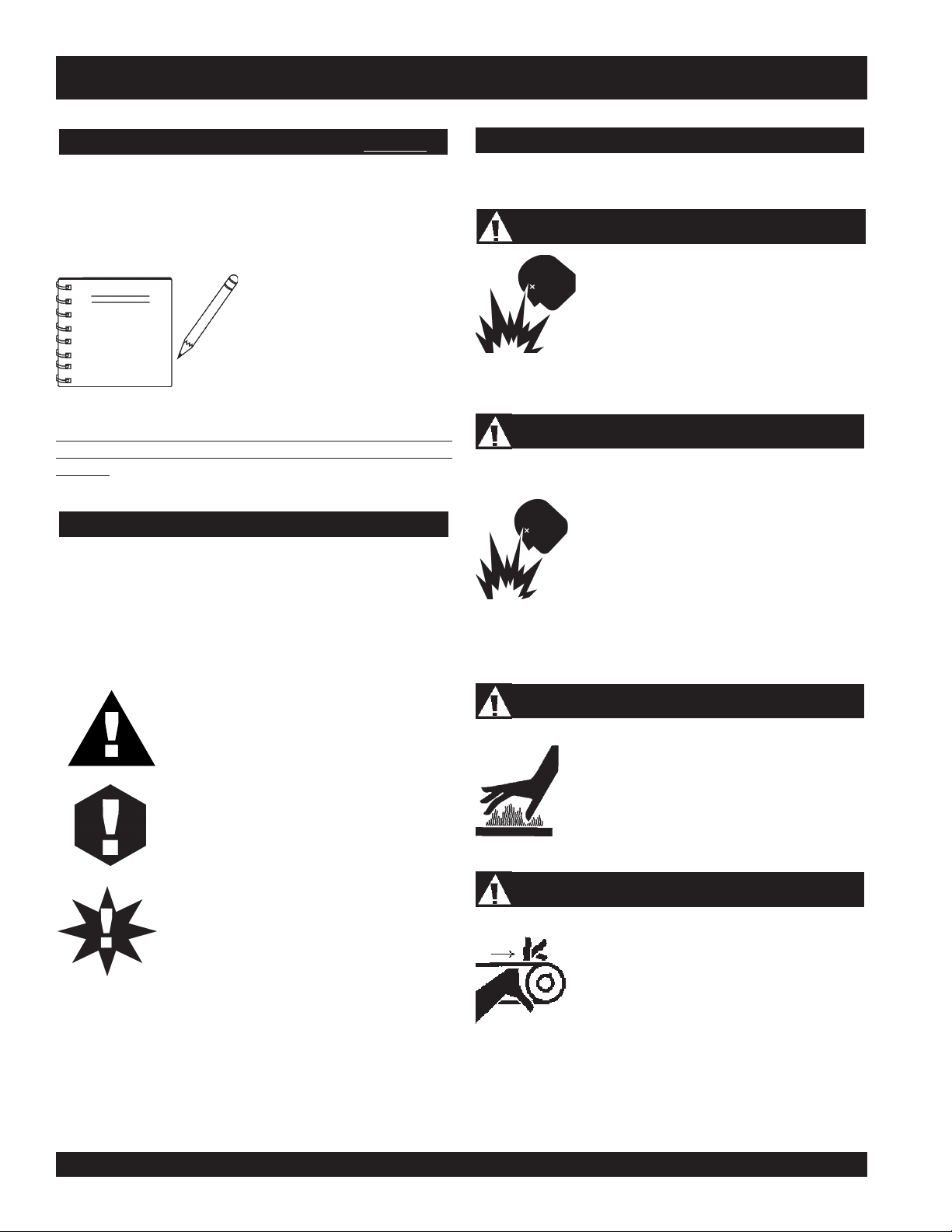
HAZARD SYMBOLS
SAFETY MESSAGE ALERT SYMBOLS
The three (3) Safety Messages shown below will inform you
about potential hazards that could injure you or others. The
Safety Messages specifically address the level of exposure to
the operator, and are preceded by one of three words: DANGER,
WARNING, or CAUTION.
Lethal Exhaust Gases
Engine exhaust gases contain poisonous
carbon monoxide. This gas is colorless and
odorless, and can cause death if inhaled.
NEVER operate this equipment in a confined
area or enclosed structure that does not
provide ample free flow air.
Explosive Fuel
GASOLINE is extremely flammable, and its
vapors can cause an explosion if ignited. DO
NOT start the engine near spilled fuel or
combustible fluids. DO NOT fill the fuel tank
while the engine is running or hot. DO NOT
overfill tank, since spilled fuel could ignite if it
comes into contact with hot engine parts or
sparks from the ignition system. Store fuel in
approved containers, in well-ventilated areas
and away from sparks and flames. NEVER
use fuel as a cleaning agent.
DANGER: You WILL be KILLED or
SERIOUSLY injured if you do not follow
directions.
WARNING: You CAN be KILLED or
SERIOUSLY injured if you do not follow
directions.
CAUTION: You CAN be injured if you
do not follow directions.
Potential hazards associated with this vibration roller operation
will be referenced with Hazard Symbols which appear
throughout this manual, and will be referenced in conjunction
with Safety Message Alert Symbols.
Burn Hazards
Engine components can generate extreme heat.
To prevent burns, DO NOT touch these areas
while the engine is running or immediately after
operations. Never operate the engine with heat
shields or heat guards removed.
Rotating Parts
NEVER operate equipment with covers, or
guards removed. Keep fingers, hands, hair and
clothing away from all moving parts to prevent
injury.
PAGE 6 — MQ-MIKASA MRH800GS ROLLER — OPERATION AND PARTS MANUAL — REV. #5 (05/27/08)
Page 7

MRH800GS — SAFETY MESSAGE ALERT SYMBOLS
Accidental Starting
ALWAYS place the engine ON/OFF switch in
the OFF position, when the vibration roller is
not in use.
Sight and Hearing hazard
ALWAYS wear approved eye and hearing
protection.
Respiratory Hazard
ALWAYS wear approved respiratory
protection.
Equipment Damage Messages
Other important messages are provided throughout this manual
to help prevent damage to your vibration roller, other property,
or the surrounding environment.
NOTE
This vibration roller, other
property, or the surrounding
environment could be damaged
if you do not follow instructions.
MQ-MIKASA MRH800GS ROLLER — OPERATION AND PARTS MANUAL — REV. #5 (05/27/08) — PAGE 7
Page 8

MRH800GS — RULES FOR SAFE OPERATION
■
NEVER touch the hot exhaust manifold,
CAUTION:
Failure to follow instructions in this manual
may lead to serious injury or even death! This
equipment is to be operated by trained and
qualified personnel only! This equipment is
for industrial use only.
The following safety guidelines should always be used when
operating the MIKASA MRH800GS Vibration Roller:
GENERAL SAFETY
■
DO NOT operate or service this equipment before
reading this entire manual.
■
This equipment should not be operated by
persons under 18 years of age.
■
NEVER operate this equipment without proper
protective clothing, shatterproof glasses, steeltoed boots and other protective devices required
by the job. ALWAYS wear slip resistant safety
shoes or boots.
■
NEVER operate this equipment when not feeling
well due to fatigue, illness or taking medicine.
muffler or cylinder. Allow these parts to
cool before servicing engine or vibration
roller.
■
High Temperatures – Allow the engine to cool before adding
fuel or performing service and maintenance functions. Contact
hot
with
■
The engine of this vibration
roller requires an adequate
free flow of cooling air.
NEVER operate the
vibration roller in any
enclosed or narrow area
where free flow of the air is
restricted. If the air flow is
restricted it will cause
serious damage to the vibration roller or engine and may
cause injury to people and property. Remember the vibration
roller's engine gives off DEADLY gases.
■
ALWAYS refuel in a well-ventilated area, away from sparks
and open flames.
components can cause serious burns.
■
NEVER operate this equipment under the
influence or drugs or alcohol.
■
NEVER use accessories or attachments, which are not
recommended by Multiquip for this equipment. Damage to
the equipment and/or injury to user may result.
■
Manufacturer does not assume responsibility for any accident
due to equipment modifications.
■
Whenever necessary, replace nameplate, operation and
safety decals when they become difficult read.
■
ALWAYS wear proper respiratory (mask), hearing and eye
protection equipment when operating the vibration roller.
■
■
■
■
■
■
■
■
ALWAYS use extreme caution when working with flammable
liquids. When refueling, stop the engine and allow it to cool.
DO NOT
explosion could result from fuel vapors, or if fuel is spilled on
a hot engine.
NEVER operate the vibration roller in
an explosive atmosphere or near
combustible materials. An explosion or
fire could result causing severe
smoke around or near the machine. Fire or
bodily
harm or even death.
Topping-off to filler port is dangerous, as it tends to spill fuel.
ALWAYS store the vibration roller in a clean, dry location out
of the reach of children.
NEVER run engine without air cleaner. Severe engine
damage may occur.
NEVER leave the vibration roller unattended, turn off engine.
CAUTION must always be observed while servicing this
vibration roller. Rotating parts can cause injury if contacted.
DO NOT leave vibration roller with engine running. Use
chock blocks if parking
vibration roller on a grade.
PAGE 8 — MQ-MIKASA MRH800GS ROLLER — OPERATION AND PARTS MANUAL — REV. #5 (05/27/08)
Page 9

MRH800GS — RULES FOR SAFE OPERATION
■
ALWAYS use extreme care when operating near obstructions,
on slippery surfaces, grades and side slopes.
■
When reversing, particularly on the edges and banks of
ditches, as well as in front of obstacles, the operator must stay
in a standing position at a safe distance from the machine.
■
When operating near any house/building or pipelines, always
check the effect of machine vibration. Stop the work if
necessary.
■
Unauthorized equipment modifications will void all
warranties.
■
Refer to the
questions or information.
■
DO NOT operate the vibration roller with the front or rear
cover open.
■
Replace any worn or damaged vibration roller components
immediately.
■
ALWAYS turn the engine
maintenance.
■
ALWAYS make sure vibration roller is correctly secured to
the trailer. Check all supports attaching the vibration roller to
the trailer and make sure they are tight.
■
ALWAYS keep the machine away from workers and obstacles.
Also keep the immediate area free of bystanders.
■
ALWAYS check the machine for loosened threads or bolts
before starting.
■
ALWAYS read, understand, and follow procedures in
Operator’s Manual before attempting to operate equipment.
■
ALWAYS be sure the operator is familiar with proper safety
precautions and operations techniques before using vibration
roller.
■
A copy of this manual shall accompany the vibration roller at
all times.
■
DO NOT use worn out hoses or couplings; inspect daily.
Engine Owner's Manual
for engine technical
OFF
before performing
■
High Temperatures – Always stop engine and allow the
engine to cool before adding fuel, oil or performing service
and maintenance functions. Contact with
cause serious burns.
■
NEVER disconnect any
These devices are intended for operator safety. Disconnection
of these devices can cause severe injury, bodily harm or even
death! Disconnection of any of these devices will void all
warranties.
Emergencies
■
ALWAYS know the location of the nearest
and
Also know the phone numbers of the nearest
doctor
invaluable in case of an emergency.
Maintenance Safety
■
■
■
■
■
■
■
Lifting
■
■
hot
components can
"emergency or safety devices"
.
fire extinguisher
first aid kit
and
NEVER lubricate components or attempt service on a running
machine.
ALWAYS allow the machine a proper amount of time to cool
before servicing.
Keep the machinery in proper running condition.
Fix damage to the machine immediately and always replace
broken parts.
Dispose of hazardous waste properly. Examples of potentially
hazardous waste are used motor oil, fuel and fuel filters.
DO NOT use food or plastic containers to dispose of
hazardous waste.
DO NOT pour waste, oil or fuel directly onto the ground,
down a drain or into any water source.
The vibration roller has an operating weight of approximately
1530 lbs. (694 kg). Use lifting equipment capable of lifting
this weight.
Make sure the engine is off before lifting the machine.
. Know the location of the nearest telephone.
fire department
ambulance
. This information will be
,
■
Use reliable cable in lifting the machine.
■
Lift upright with sufficient bearing capacity to prevent machine
from tilting or slipping.
■
When lifting, keep the machine away from workers and
animals.
MQ-MIKASA MRH800GS ROLLER — OPERATION AND PARTS MANUAL — REV. #5 (05/27/08) — PAGE 9
Page 10

MRH800GS — OPERATION AND SAFETY DECALS
Figure 1 displays the operation and safety decals as they appear on the vibration roller. Should any of these decals become
damaged or unreadable, contact the Multiquip Parts Department for a replacement set.
Figure 1. Operation and Safety Decals
PAGE 10 — MQ-MIKASA MRH800GS ROLLER — OPERATION AND PARTS MANUAL — REV. #5 (05/27/08)
Page 11
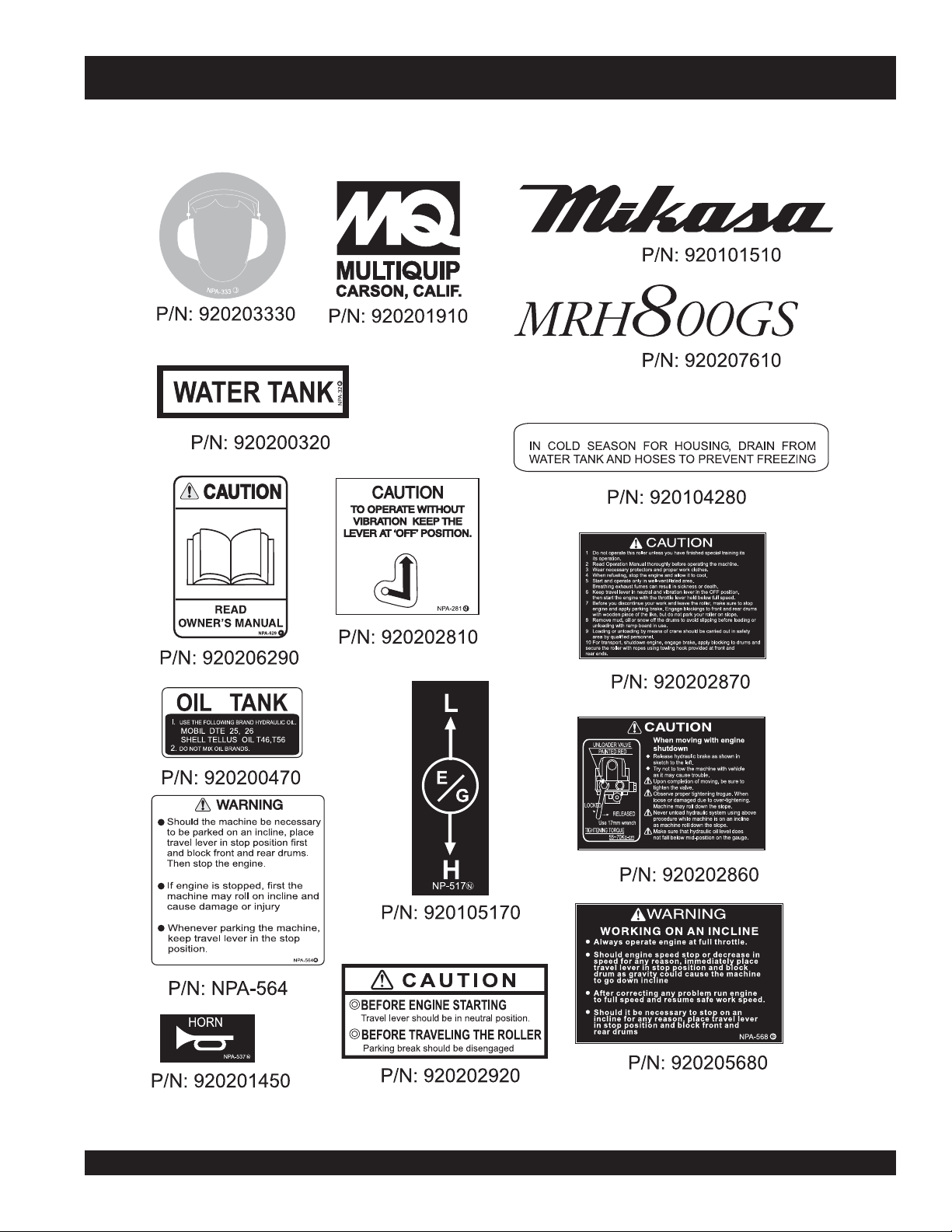
MRH800GS — OPERATION AND SAFETY DECALS
Figure 1. Operation and Safety Decals (Continued)
MQ-MIKASA MRH800GS ROLLER — OPERATION AND PARTS MANUAL — REV. #5 (05/27/08) — PAGE 11
Page 12

MRH800GS — ROLLER SPECIFICATIONS
snoisnemiD )mm0601x296x0762(ni7.14x2.72x501
retemaiDmurD)mm604(.ni61
htdiWmurD)mm056(.ni6.52
SNOITACIFICEPSRELLOR.1ELBAT
ecnaraelCbruC)m
gnahrevOediS)mm12(.ni38.
)retawhtiw(thgieWgnitarepO)gk496(.sbl0351
ycneuqerFnoitarbiVmpv003,3
roFlagufirtneCfgk/nk004,2/5.32
ec
metsySevirDrotoMciluardyH
metsySnoitarbiVemarF
dohteMnoitarbiVevirDtleB
otarbiVniwT
tfahSr
ytililbaedarGseerged02
deepSgnikroW)hpk8.4-0(hpm3-0
yticapaCknaTleuF)sretil1.7(snollag88.1
m342(.ni6.9
tacirbuL)sretil52(snollag6.6
liOgni
yticapaCknaTretaW)sretil04(snollag75.01
ledoMenignE23MS093XGadnoH
tStratSlioceR/cirtcelE
PAGE 12 — MQ-MIKASA MRH800GS ROLLER — OPERATION AND PARTS MANUAL — REV. #5 (05/27/08)
metsySgnitra
Page 13
MRH800GS — ENGINE SPECIFICATIONS
ledoM23M1KS093XGADNOH
SNOITACIFICEPSENIGNE.2ELBAT
epyT
ekortSXeroB
tnemecalpsiDmc983(ni-uc07.32
tuptuOxaM.M.P.R0063/.P.H0.31
enignE
yticapaCknaTleuF)sretil5.6(snollag27.1
leuF enilosaGelibomotuAdedaelnU
yticapaCliOebuL)sretil1.1(strauq61.1
metsyStrelAliOseY
dohteMlortnoCdeepS epyTthgiew-ylFlagufirtneC
dohteMgnitratStratSlioceR/cirtcelE
noisnemiD
)HxWxL(
.ni03.2X.ni09.2
).mm85xmm37(
3
)
.ni4.71X7.71x0.51
).mm344X054X083(
,VHO,rednilyCelgniS,ekorts4delooc-riA
enignEenilosaGtfahSlatnoziroH
thgieWteNyrD
).gK13(sbl4.86
MQ-MIKASA MRH800GS ROLLER — OPERATION AND PARTS MANUAL — REV. #5 (05/27/08) — PAGE 13
Page 14

MRH800GS — VIBRATION ROLLER DIMENSIONS
SNOISNEMID.3ELBAT
A.ni501.mm0762
B.ni75.mm5441
HTGNEL
HTDIW
THGIEH
C.ni01.mm552
D.ni8.22.mm085
E.ni8.31.mm053
F.ni2.72.mm296
G.ni6
H.ni3.87.mm0991
I.ni5.64.mm0811
J.ni4.73.mm059
K.ni7.14.mm0601
L.ni6.9.mm542
.31.mm643
Figure 2. MRH800GS Vibration Roller Dimensions
PAGE 14 — MQ-MIKASA MRH800GS ROLLER — OPERATION AND PARTS MANUAL — REV. #5 (05/27/08)
Page 15

The Mikasa Model MRH800GS is a powerful compacting
tool capable of applying a tremendous force in consecutive
impacts to a soil surface. Its applications include soil compacting
for backfilling for gas pipelines, water pipelines and cable
installation work.
The impact force of the MRH800GS levels and uniformly
compacts voids between soil particles to increase dry density.
Features include:
Hydraulic transmission to allow speed change without
gear shifting.
Deadman device which when pressed or hit will
cause the travel lever to return to neutral position
bringing the machine to a stop.
A horn to warn of machine’s approach.
Low engine oil level shut down
Non-corrosive water tank for the sprinkler system with a
capacity of more than 10 gallons.
Lifting hook to transport machine.
MRH800GS — FEATURES
Front bumper and working light.
Narrow profile with less than one inch wall clearance.
Narrower width allows access to tighter areas. No
exposed hydraulic hoses.
Oil bath lubricated bearings and external vibration
for less servicing and more dependability.
Front and rear drum scrapers.
Drum sprinkler system controls located near the
operator.
Easy access to hydraulic components and hydraulic
filter.
MQ-MIKASA MRH800GS ROLLER — OPERATION AND PARTS MANUAL — REV. #5 (05/27/08) — PAGE 15
Page 16

6
MRH800GS — VIBRATION ROLLER COMPONENTS
7
1
2
5
3
11
4
9
8
10
Figure 3. MRH800GS Vibration Roller Components
PAGE 16 — MQ-MIKASA MRH800GS ROLLER — OPERATION AND PARTS MANUAL — REV. #5 (05/27/08)
Page 17

MRH800GS — VIBRATION ROLLER COMPONENTS
Figure 3 illustrates the location of the major components
for the MRH800GS Vibration Roller. The function of each
component is described below:
1. Fuel Tank/Cap – Fill with diesel fuel. Fuel tank holds
approximately 2 gallons (7.5 liters). DO NOT top off fuel.
Wipe up any spilled fuel immediately.
2. Hydraulic Oil Tank - Fill with proper grade of hydraulic oil.
Check fluid level using the hydraulic oil gauge.
3. Front Headlights – Activate using switch on control
handle. Use to illuminate ground durring nighttime or low
light operating conditions.
4. Vibration Rollers – 25-inch wide steel drums that provide
compaction force in the compaction and patching of asphalt
type surfaces.
6. Center Cover – When opened and supported by strut,
provides access to
clutch box
6. Water Tank– Holds 10.57 gallons (40 liters) for the sprinkler
system.
.
oil pump and filter, battery, V-belt, and
7. Lifting Hook – Used to lift the machine with crane or other
lifting device.
8. Hydraulic Oil Gauge – Indicates the hydraulic oil level.
9. Engine – This machine uses the Honda GX390K1SM32
gasoline engine. Refer to page 20 for more information.
10. Parking Brake – Makes sure machine will not accidentally
move when parked or not in use.
11. Vibrator Oil Level Plug – Remove to check vibrator oil
level.
MQ-MIKASA MRH800GS ROLLER — OPERATION AND PARTS MANUAL — REV. #5 (05/27/08) — PAGE 17
Page 18
3
4
MRH800GS — HANDLE BAR/LEVER COMPONENTS
1
2
6
5
Figure 4. MRH800GS Lever Components
PAGE 18 — MQ-MIKASA MRH800GS ROLLER — OPERATION AND PARTS MANUAL — REV. #5 (05/27/08)
Page 19

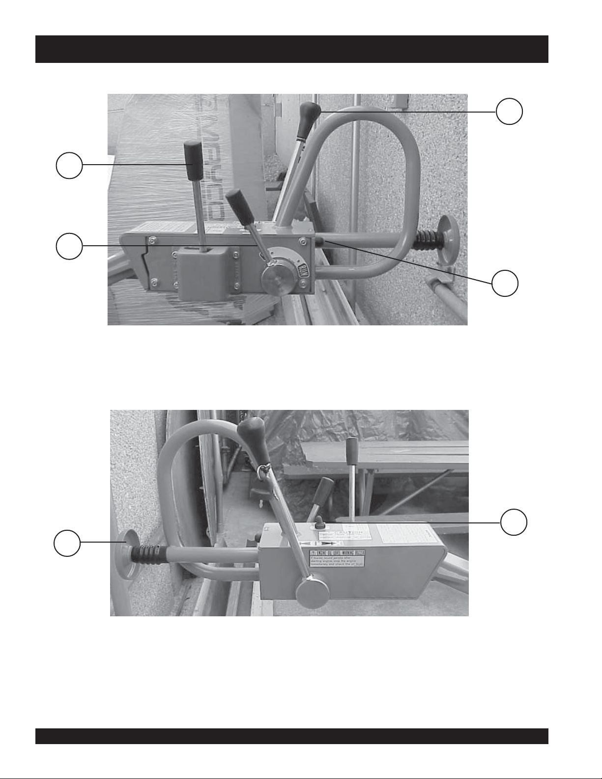
MRH800GS — HANDLE BAR/LEVER COMPONENTS
HANDLE BAR/LEVER COMPONENTS
Figure 4 illustrates the location of the major lever
components on the handle bar of the machine. Each
component is described below:
1. Travel Lever – Controls the direction of travel of the
machine (forward and reverse).
4. Horn Button – When pressed, gives a warning sound of
the machine approaching.
3. Vibration Lever – Turns vibration on and off.
4. Throttle Lever – Controls the start up of the machine.
5. Dead-Man Device – When pressed or hit while traveling
in reverse, causes the travel lever to return to neutral
position to stop the machine.
6. Light ON/OFF Switch - Turns headlight on and off.
MQ-MIKASA MRH800GS ROLLER — OPERATION AND PARTS MANUAL — REV. #5 (05/27/08) — PAGE 19
Page 20
INITIAL SERVICING
MRH800GS — ENGINE COMPONENTS
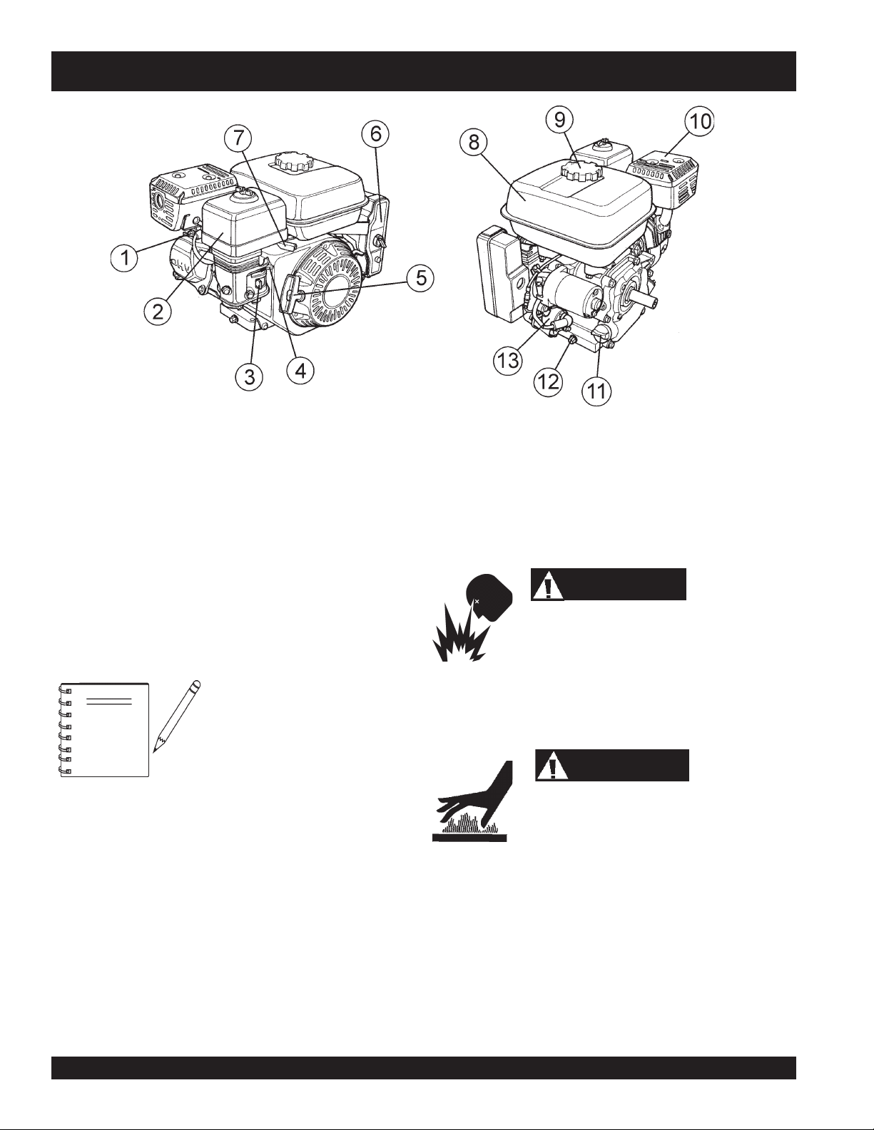
Figure 5. Engine Controls and Components
The engine (Figure 5) must be checked for proper lubrication and
filled with fuel prior to operation. Refer to the manufacturers engine
manual for instructions & details of operation and servicing.
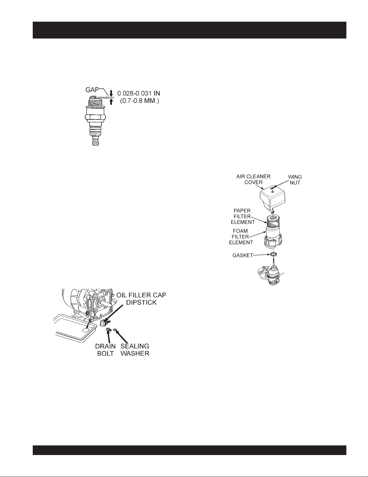
1. Spark Plug – Provides spark to the ignition system. Set
spark plug gap to 0.6 - 0.7 mm (0.028 - 0.031 inch) Clean
spark plug once a week.
2. Air Cleaner – Prevents dirt and other debris from entering
the fuel system. Remove wing-nut on top of air filter
cannister to gain access to filter element.
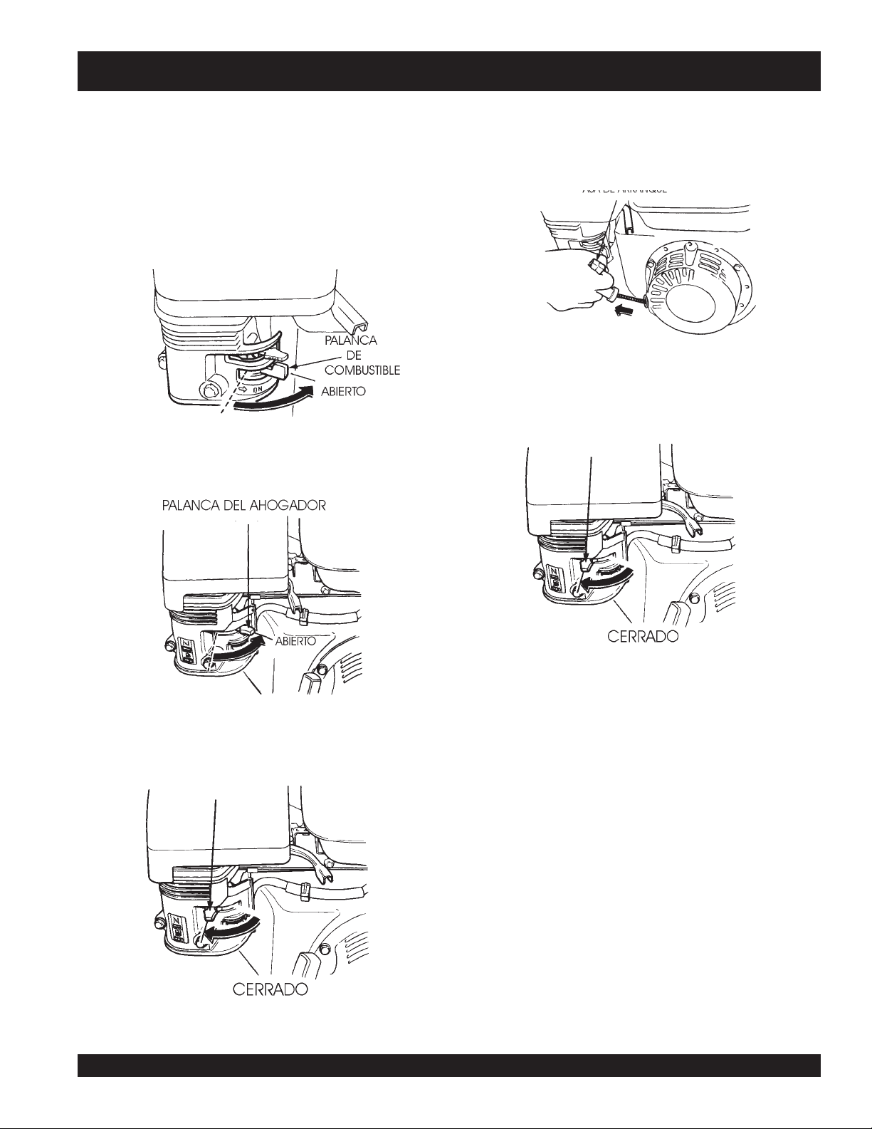
3. Fuel Valve Lever – OPEN to let fuel flow, CLOSE to stop
the flow of fuel.
Operating the engine without an air
NOTE
4. Choke Lever – Used in the starting of a cold engine, or in
cold weather conditions. The choke enriches the fuel
mixture.
5. Recoil Starter (pull rope) – Manual-starting method. Pull
the starter grip until resistance is felt, then pull briskly and
smoothly.
6. Engine ON/OFF Switch – ON position permits engine
starting, OFF position stops engine operations.
7. Throttle Lever – Used to adjust engine RPM speed (lever
advanced forward
FAST
).
filter, with a damaged air filter, or a
filter in need of replacement will
allow dirt to enter the engine,
causing rapid engine wear.
SLOW
, lever back toward operator
9. Fuel Filler Cap – Remove this cap to add unleaded
gasoline to the fuel tank. Make sure cap is tightened
securely. DO NOT over fill.
10. Muffler – Used to reduce noise and emissions.
11. Engine Oil FIller Cap/Dipstick – Remove to check amount
attempt to start the engine until the fuel residue has been completely
wiped up, and the area surrounding the engine is dry.
and condition of oil in crankcase. Refill or replace with
operating. NEVER operate the engine with the muffler removed.
ecommended type oil as listed in table 2. .
12. Oil Drain Plug –Remove to drain crankcase oil.
13. Engine Starter – Starts engine when ignition key is rotated
to the “ON” position.
DANGER
Adding fuel to the tank should be done only when
the engine is stopped and has had an opportunity
to cool down. In the event of a fuel spill, DO NOT
WARNING
Engine components can generate extreme heat.
To prevent burns, DO NOT touch these areas while
the engine is running or immediately after
8. Fuel Tank – Holds unleaded gasoline. For additional
information refer to engine owner's manual.
PAGE 20 — MQ-MIKASA MRH800GS ROLLER — OPERATION AND PARTS MANUAL — REV. #5 (05/27/08)
Page 21

NOTE PAGE
MQ-MIKASA MRH800GS ROLLER — OPERATION AND PARTS MANUAL — REV. #5 (05/27/08) — PAGE 21
Page 22

MRH800GS — INSPECTION
DANGER
NEVER operate the
compactorin a confined
area or enclosed area
structure that does not
provide ample
.
of air
ALWAYS wear approved eye and hearing
protection before operating the compactor.
Before Starting
1. Read safety instructions at the
beginning of manual.
2. Remove dirt and dust, particularly
in theengine cooling air inlet,
carburetor and air cleaner.
3. Check the air filter for dirt and dust.
If air filter is dirty, replace air filter
with a new one as required.
4. Check carburetor for external dirt and dust. Clean with dry
compressed air.
free flow
3. Insert and remove the dipstick without screwing it into the
filler neck. Check the oil level shown on the dipstick.
4. If the oil level is low, fill to the edge of the oil filler hole with the
recommended oil type (Table 3). Maximum oil capacity is
1.16 quarts (1.1 liters).
Checking The Hydraulic System
1. Check the oil tank level gauge (Figure 7). Oil level
should be at the middle indication of the gauge or
higher. Fill as required
2. Check the surroundings of the oil tank, hydraulic
pump and motor for oil leakage.
Level should
be middle of
gauge or
higher
Figure 7. Hydraulic System Oil Level Gauge
5. Check fastening nuts and bolts for tightness.
DANGER
6. Understand the geographical features and regulations of
the job site.
Engine Oil Check
1. To check the engine oil level, place the compactor on secure
level ground with the engine stopped.
2. Remove the filler dipstick from the engine oil filler hole
(Figure 6) and wipe clean.
Figure 6. Engine Oil Level
ETIECAEDOPIT.4ALBAT
nóicatsE arutarepmeT etiecaedopiT
Checking The V-Belt
1. Remove the 2 bolts, one on each side of the center
cover, with a #13 socket wrench. Open the center
cover of the machine and support it with the strut by
inserting its end to the hole in the base (Figure 8).
2. Check V-belt for proper tension. Insufficient tension
causes weak vibration.
Center
Cover
Strut
V-Belt
Always keep hands and fingers away from pinch
points. Do not allow anyone to reach in on
dangerous sections of the machine to avoid any
accidents.
onareV atlasámóC°52 03-W01EAS
oñotO/arevamirP C°01~C°52 02/03-W01EAS
onreivnI ajabsámóC°0 01-W01EAS
PAGE 22 — MQ-MIKASA MRH800GS ROLLER — OPERATION AND PARTS MANUAL — REV. #5 (05/27/08)
Figure 8. Checking V-Belt Tension
Page 23

MRH800GS — INSPECTION
Checking The Vibrator Oil Level
1. Check vibrator casing for any oil leakage.
2. If any leakage is noticed, remove the level plug on the side
of the plate (Figure 9).
3. Check the oil level.
Vibrator Oil
Level Plug
Figure 9. Checking Vibrator Oil Level
Fuel Check
1. Remove the fuel cap located on top of the engine fuel tank.
2. Visually inspect to see if the fuel level is low. If fuel is low,
replenish with unleaded gasoline using a strainer for
filtration. DO NOT top-off fuel. Wipe up any spilled fuel
immediately!
Checking Levers and Horn
1. Check travel, vibration, and throttle levers to make sure
they are functioning properly (Figure 4).
2. With travel lever placed in reverse, push the deadman
device and verify that the travel lever returns to neutral
position. The travel lever stays in neutral position once the
deadman device is released.
3. Press the horn and verify that it functions properly.
Checking Scrapers
1. Check scrapers and make sure that they are not clogged
with mud, bent or damaged (Figure 11).
2. Adjust clearance between drums and scrapers as
necessary.
DANGERDANGER
DANGER
DANGERDANGER
Motor fuels are highly
flammable and can be
dangerous if mishandled. DO
NOT smoke while refueling.
DO NOT attempt to refuel the pump if the
engine is
Checking Water Tank
1. Check the water tank to see if filled. Add water if necessary.
hot! or running
The water tank has a capacity of approximately 10 gallons
(40 liters) (Figure 10).
Figure 10. Checking Water Tank
.
CAUTION :
Scrapers
Figure 11. Checking Scrapers
Checking Bolts, Nuts and Screws
1. Check bolts, nuts, and screws on various parts of the
machine, including the engine, for proper tightness.
Positioning the Handle Bar
1. Release the handle bar release pin (Figure 12) and position
the handle bar to the lowered position before starting
operation.
2. When machine is not in use, release the handle bar release
pin and position the handle bar to the upright position.
Handle Bar
Release Pin
Be careful not to confuse the water tank with the
oil tank.
MQ-MIKASA MRH800GS ROLLER — OPERATION AND PARTS MANUAL — REV. #5 (05/27/08) — PAGE 23
Figure 12. Positioning the Handle Bar
Page 24
MRH800GS — OPERATION
STARTING THE ENGINE
The engine can be started by motor (electric) or manually
(recoil). Refer to Figures 3 and 4 for the location of
controls and components.
4. Place the
if starting a
CAUTION :
Make sure to follow all safety rules referenced in
the safety section of this manual before operating
roller. Keep work area clear of debris and other
objects that could cause damage to the roller or
bodily injury.
CAUTION :
When the engine is running, NEVER turn the
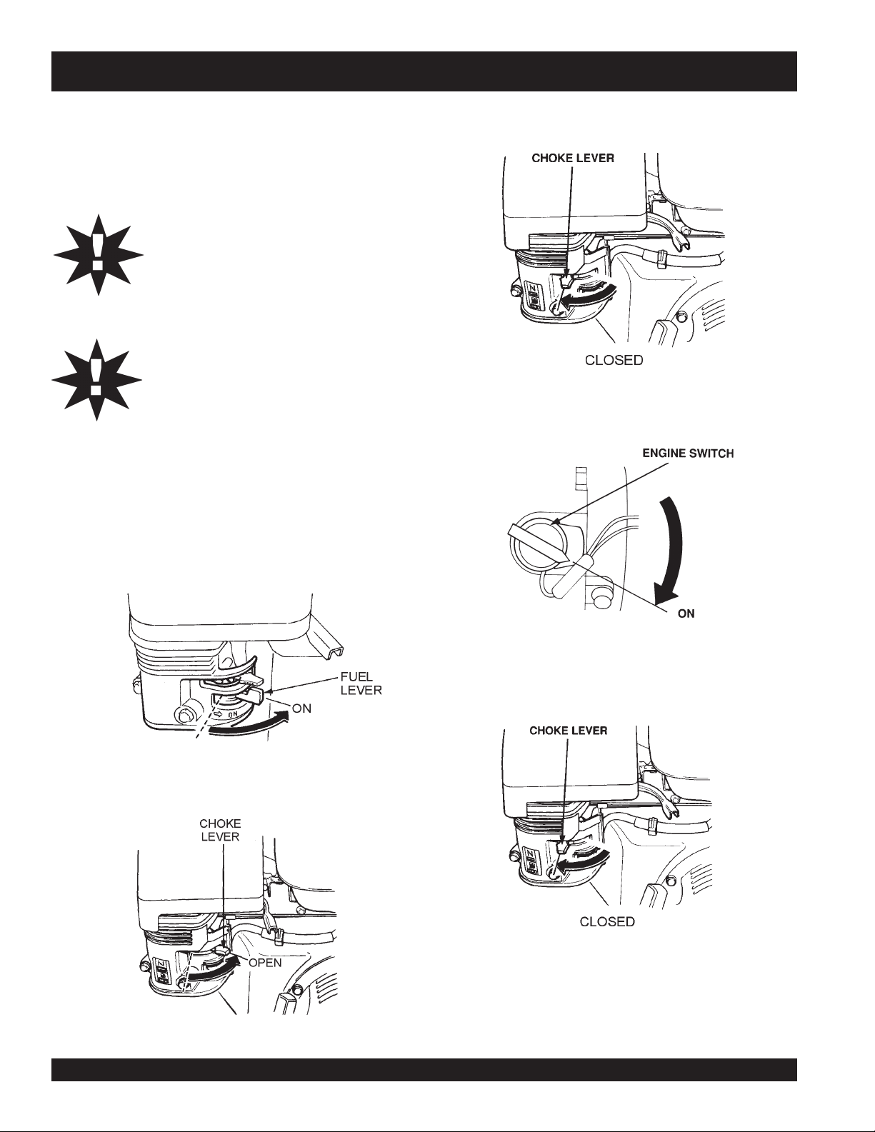
starter key to the START position
Electric Start
1. On the control handle:
A. Move the
B. Move the
throttle lever
travel lever
to the NEUTRAL position.
to the RUN position.
5. Place the
position.
choke lever
warm engine
Figure 15. Engine Choke Lever (Closed)
engine ON/OFF switch
(Figure 15) in the "
or the
temperature is warm.
CLOSED
(Figure 16) in the "
" position
ON
"
C. Move the
2. Place the engine
position.
Figure 13. Engine Fuel Valve Lever (ON Position)
3. Place the
if starting a
vibration lever
fuel valve lever
choke lever
cold
(Figure 14) in the "
engine.
to the OFF position.
(Figure 13) to the "ON"
OPEN
" position
Figure 16. Engine ON/OFF Switch (ON Position)
7. If the engine has started, slowly return the choke lever
(Figure 17 ) to the
started repeat steps 1 through 6.
Figure 17. Choke Lever (Closed)
CLOSED
position. If the engine has not
8. Before the roller is placed into operation, run the engine for
several minutes. Check for fuel leaks, and noises that would
be associated with a loose component.
Figure 14. Engine Choke Lever (Open)
PAGE 24 — MQ-MIKASA MRH800GS ROLLER — OPERATION AND PARTS MANUAL — REV. #5 (05/27/08)
Page 25
MRH800GS — OPERATION
Recoil Start
1. On the control handle:
A. Move the
B. Move the
C. Move the
2. Place the engine
position.
Figure 18. Engine Fuel Valve Lever (ON Position)
3. Place the
if starting a
throttle lever
travel lever
vibration lever
fuel valve lever
choke lever
cold
(Figure 19) in the "
engine.
to the RUN position.
to the NEUTRAL position.
to the OFF position.
(Figure 18) to the "ON"
OPEN
" position
6. Grasp the starter grip (Figure 21) and slowly pull it out. The
resistance becomes the hardest at a certain position, corresponding to the compression point. Pull the starter grip
briskly and smoothly for starting.
Figure 12. Starter Grip
7. If the engine has started, slowly return the choke lever
(Figure 22 ) to the
started repeat steps 1 through 6.
CLOSED
position. If the engine has not
Figure 22. Choke Lever (Closed)
8. Before the roller is placed into operation, run the engine for
Figure 19. Engine Choke Lever (Open)
4. Place the
if starting a
choke lever
warm engine
Figure 20. Engine Choke Lever (Closed)
MQ-MIKASA MRH800GS ROLLER — OPERATION AND PARTS MANUAL — REV. #5 (05/27/08) — PAGE 25
(Figure 20) in the "
or the
temperature is warm.
CLOSED
" position
several minutes. Check for fuel leaks, and noises that would
be associated with a loose component.
Page 26

MRH800GS — OPERATION
TRAVELING
1. Before starting to travel, make sure to release parking brake
located on the left side of the rear roller. If the parking brake
lever is tight, moving the roller back and forth will make it
easier (Figure 23.
Parking
Brake
(Released
Position)
Figure 23. Parking Brake
2. With the throttle lever in the RUN position, increase
the engine rotation.
3. Push the travel lever forward slightly. This will cause
the roller to travel forward at slow speed.
4. To increase the travel speed, push the travel lever
further.
5. Travel speed can be varied between 0 and 3 km/h
(both forward and reverse).
6. Push the travel lever backward to go in the reverse
direction.
VIBRATING
1. Shift the vibration lever away from its off position. The
vibration lever will automatically spring forward and the
roller will start vibrating (Figure 24).
CAUTION :
Off Position of
Vibration Lever
Figure 24. Vibration Lever
Using vibration with clutch slipping causes
the clutch to burn. Also, vibration should not
be used over completely compacted area,
paved road surface, or with stationary roller.
CAUTION :
DO NOT reduce speed during work. When
shifting travel lever from forward to reverse,
be sure to stop the lever at the NEUTRAL
position first before moving the lever to the
opposite direction. DO NOT shift the lever
from forward to reverse (or reverse to
forward) in one motion.
CAUTION :
After test travel, shut down engine and
check for any problems including oil
leakage. If any trouble is found, correct the
problem before attempting to operate the
roller again.
PAGE 26 — MQ-MIKASA MRH800GS ROLLER — OPERATION AND PARTS MANUAL — REV. #5 (05/27/08)
WATERING
1. For watering work, turn the water cocks clockwise, at the
rear of the machine, to start sprinkling. (Figure 25).
Watercock
for Front
Drum
Watercock
for Rear
Drum
Figure 25. Water Cocks
Page 27

SAFETY FEATURES
MRH800GS — OPERATION
1. A horn is provided to warn of approach.
2. The dead man device prevents accidental traveling
in reverse. It automatically makes the travel lever
return to neutral position by stopping the machine
when an object comes in contact with the dead man
device.
STOPPING
1. With travel lever in the neutral position, and the
vibration lever in the off position, return the throttle
lever to the START position. Allow the machine to
cool down for 3 to 5 minutes.
2. Push the throttle lever forward to stop the engine. In
a motor start, return the key switch to the STOP
position as soon as the engine stops.
Bypass
Valve
Bolt
CAUTION :
CAUTION :
Neglecting to return the key switch to the
STOP position will cause the battery to
discharge making start up impossible the
next time.
3. After the engine stops, close the fuel cock.
4. Lock the parking brake by pulling the brake lever
and rotating it 90 degrees clockwise.
Parking brake system should
NOTE
always be kept clean to avoid
mud deposits.
LIFTING
1. Use a crane or lift to load and unload the machine. A
skilled crane operator is required to perform the job.
2. When lifting the machine, check for any damaged or
loose bolts, lifting hooks, and shock mounts.
3. Check any damaged or loose bolts in the guard frame to
avoid machine sliding off.
4. Make sure that the machine is shut off before machine is
lifted.
5. Use reliable cable for lifting.
6. ALWAYS lift the machine vertically and keep the
machine away from workers and animals.
Figure 26 Location of Bypass Valve Bolt
NEVER tow roller with any type of vehicle.
Doing so will damage the hydraulic system.
NEVER perform unloading procedure on a
slope. This may cause roller to roll down if
parking brake or blocking is deficient.
7. DO NOT lift the machine higher than the required
UNLOADING
1. If you need to move the roller by pushing it manually
once engine is stopped, loosen bolt of bypass valve
on oil pump by one rotation counterclockwise. This
will cause the hydraulic break to disengage and allow
the roller to be moved more easily (Figure 26).
2. After moving, tighten the bolt again. Tightening torque
is 55 to 70 kgf-cm.
MQ-MIKASA MRH800GS ROLLER — OPERATION AND PARTS MANUAL — REV. #5 (05/27/08) — PAGE 27
height.
TRANSPORTING
1. ALWAYS make sure that the machine is shut off
while being transported.
2. Check that the fuel cap is properly closed and
tightened.
3. When traveling long distances or on rugged terrain,
drain the fuel of the machine before transporting.
4. Tie down the machine securely on the
transportation so that it will not move or topple over.
Page 28

MRH800GS — MAITENANCE
CAUTION:
Inspection and other services should
carried out on hard and level ground with the
engine shutdown.
Inspection and Maintenance Service Tables.
1. To make sure your roller is always in good working condition
before using, carry out the maintenance inspection in
accordance with Tables 5 through 7.
SG008-HRM.5ELBATNOITCEPSNIENIHCAM
METI
gnissiMroesooL
swercS
straPdegamaD
FOSRUOH
NOITAREPO
sruoh8yrevE
)yadyreve(
sruoh8yrevE
)yadyreve(
always
SKRAMER
be
METINOITAREPOFOSRUOH
enthgiT
sdaerhT
tnemhsinelpeR
Daily Service
kcehCgulPkrapS)keewyreve(sruoh04yrevE
kaeLleuFroliO)yadyreve(sruoh8yrevE
gninetsaFfoss
dnakcehCliOenignE
tnemecalpeRliOenignE
gninaelCretliFriAsruoh001
SG008-HRM.6ELBATKCEHCENIGNE
)level
yrevE
)yadyreve(sruoh8yrevE
)yadyreve(sruoh8yrevE
sothsinelpeR(
sruoh001
mumixamdeificep
ot05yrevenehtsruoh52tsrifretfA
.kcehcenignenosliatedroflaunamenigneetarapeseeS
traPmetsyS
kcehCliOrotarbiVsru
liOrotarbiV
tnemecalpeR
kcehCliOciluardyHsruoh001yrevE32egapeeS
liO
ciluardyH
tnemecalpeR
kcehC)hctulc(tleb-Vsruoh002yrevE32eg
CAUTION:
These inspection intervals are for operation under
normal conditions. Adjust your inspection intervals
based on the number hours roller is in use, and
particular working conditions. Fuel piping and
connections should be replaced every 2 years.
gnillortnoCfonoitcnuF
kaeLmetsySciluardyHsruoh001yrevE
sruoh8yrevE
)yadyreve(
oh001yrevE32egapeeS
sruoh003yrevE32egapeeS
002retfatsriF
yreveneht,sruoh
sruoh000,1
z
Check for leakage of fuel or oil.
z
Check for loose screws including tightness. See Table 7
below (tightening torque ), for retightening:
)mc/gk.ni(EUQROTGNINETHGIT.7ELBATRETEMAID
mm6 mm8 mm01 mm21 mm41 mm61 mm81 mm02
lairetaM
T4 07 051 003 005 057 001,1 004,1 000,2
T8-6 001 052 005 008 003,1 000,2 007,2 008,3
T11 051 004 008 002,1 000,2 009,2 002,4 006,5
42egapeeS
apeeS
* 001
z
Remove soil and clean the bottom of compaction plate.
z
Check hydraulic pump, piping and hose for any leakage. A
~003
~056
053
007
)munimulafositrap-retnuocesacnI(*
)dednahthgirllaeraenihcamsihthtiwesunisdaerhT(
kramsilairetamfoytilauqdnalairetaM
.wercsdna,tlobhcaenode
loosened hydraulic hose can be a cause for leakage. Check
hydraulic hose connections with wrench applied for
tightness.
z
Check engine oil.
PAGE 28 — MQ-MIKASA MRH800GS ROLLER — OPERATION AND PARTS MANUAL — REV. #5 (05/27/08)
Page 29
MRH800GS — MAINTENANCE
Spark Plug
1. Remove and clean the spark plug (Figure 27).
2. Adjust the spark gap to 0.028 ~0.031 inch (0.6~0.7 mm). This
unit has electronic ignition, which requires no adjustments.
Figure 27. Spark Plug Gap
Engine Oil Replacement
1. Replace engine oil, first in 25 hours of operation and every
50 to 100 hours afterwards.
2. Drain the engine oil when the oil is
Figure 28.
3. Remove the oil drain bolt and sealing washer and allow
the oil to drain into a suitable container.
warm
as shown in
Air Filter
1. Remove the air cleaner cover and foam filter element as
shown in Figure 23.
2. Tap the paper filter element (Figure 29) several times on a
hard surface to remove dirt, or blow compressed air [not
exceeding 30 psi (207 kPa, 2.1 kgf/cm
element from the air cleaner case side.
Brushing will force dirt into the fibers. Replace the paper filter
element if it is excessively dirty.
3. Clean foam element in warm, soapy water or nonflammable
solvent. Rinse and dry thoroughly. Dip the element in clean
engine oil and completely squeeze out the excess oil from the
element before installing.
2
)] through the filter
NEVER
brush off dirt.
4. Replace engine oil with recommended type oil as listed
in Table 3. Engine oil capacity is 1.16 quarts (1.1 liters).
DO NOT overfill.
5. Install drain bolt with sealing washer and tighten securely.
ROLLER INSPECTION AND ADJUSTMENT
1. Refer to Table 7 for oil and grease requirements.
2. Check oil tank level daily.
3. Check the machine for oil leak and proper function of lever,
cables, and links daily.
Figure 28. Engine Oil (Draining)
Figure 29. Engine Air Filter
MQ-MIKASA MRH800GS ROLLER — OPERATION AND PARTS MANUAL — REV. #5 (05/27/08) — PAGE 29
Page 30

zz
z
Do not close the exhaust outlet of battery. The gas pressure
MACHINE MAINTENANCE
1. At the end of each day’s operation, wash down dust and
dirt off the machine. Clean area around drums ad scrapers
making sure all mud is removed.
2. Drain water tank completely.
3. Cover the machine to prevent dust and store in dry place
away from sun exposure.
LONG TERM STORAGE
1. Conduct thorough lubrication and oil change.
2. Disconnect battery terminals and dismount battery from
machine. Store battery.
3. If there a possibility that ambient temperature will drop
below freezing point, add antifreeze agent to coolant.
4. Cover the inlet and outlet of air cleaner and muffler
securely.
5. Store machine indoors. DO NOT leave outdoors.
6. Refer to Table 7 for lubrication necessary for the machine.
BATTERY MAINTENANCE
DANGER :
Lead-acid battery contains sulfuric
acid, which may damage eyes or
skin on contact.
zz
building up in the battery may cause explosion.
zz
z
Before using a battery charger, read and understand the
zz
charger instruction manual thoroughly.
zz
z
Charge the battery in a non-spark, well-ventilated area. Avoid
zz
fire from cigarette sparks or matches.
1. If a battery has not been used for some time, reduce
the charge level initially to protect each plate inside
the battery.
2. Check the battery terminals periodically to ensure
that they are in good condition.
3. Use wire brush or sand paper to clean the battery
terminals.
4. Check battery for cracks or any other damage. If white
pattern appears inside the battery or paste has
accumulated at the bottom, replace the battery.
5. Measure the specific gravity of electrolyte:
completely charged: 1.270 - 1.290
needs charging: 1.260 or lower
6. If the machine will not be in operation for a long
period of time, charge the battery sufficiently, tighten
all caps, correctly, store in cool dry place and check
the battery charge level every month to maintain the
performance of the battery.
BATTERY CABLE CONNECTION
MRH800GS — MAINTENANCE
1. When removing cable, disconnect the ground side (normally
negative) first (Figure 30).
FOR YOUR SAFETY:
zz
z
Always wear a face shield to avoid acid getting into the eyes.
zz
If acid gets in contact with eyes, flush immediately with clean
water and get medical advice.
zz
z
Wear rubber gloves and protective clothes to keep acid off
zz
skin. If acid gets in contact with skin, wash off immediately
with clean water.
zz
z
Use a flashlight to check battery electrolyte level. Always
zz
check the engine is stopped.
zz
z
DO NOT charge battery or jump-start engine when the
zz
battery is frozen. Warm the battery to 15 degrees F or battery
may explode.
zz
z
Replace the battery with the same or similar capacity battery
zz
or battery may explode.
PAGE 30 — MQ-MIKASA MRH800GS ROLLER — OPERATION AND PARTS MANUAL — REV. #5 (05/27/08)
Negative
Terminal
Figure 30. Battery Connection
2. When installing cable connect the ground side (normally
negative) last.
Positive
Terminal
Page 31

MRH800GS — MAINTENANCE
FORWARD AND REVERSE TRAVEL ADJUSTMENT
1. If neutral position for forward and reverse travel has been
displaced, conduct the neutral adjustment.
2. If roller travels forward with the ball of ball plunger remaining
in V slot of the guide, loosen M8 bolt and slide the slide
plate slightly toward the engine. If the roller travels
backward, slide the plate towards side plate (Figure 31).
Plunger
M8 Bolt
Figure 31. Adjustment of Neutral Position
3. With M8 bolt tightened, start engine and check the neutral
for forward and reverse. If still displaced, repeat the
procedure.
4. If neutral position of forward/reverse lever has been
displaced, use the turn buckle located on the oil pump side
of forward/reverse cable.
Guide
Slide Plate
CAUTION:
CAUTION :
NEVER attempt to check the V-belt with the en-
gine running. Severe injury can occur if your hand
gets caught between the V-belt and the clutch
(Figure 33). Always use safety gloves.
CLUTCH
PULLEY
VIBRATOR
PULLEY
Figure 33. V-Belt Hazard
Excessive turning of front nut may cause the
sliding engagement of clutch to take place or
no vibration takes place even when vibration
lever is engaged.
On the other hand, insufficient turn may cause
sliding engagement of clutch even when the
vibration lever is placed in the OFF position or
for vibration to remain engaged.
VIBRATION CLUTCH ADJUSTMENT
1. Move vibration lever to the OFF position.
2. Loosen the front and rear nuts at the end of vibration clutch
cable (Figure 32).
3. Turn in the nut on the front side again and at the position
that release fork starts to move, turn in the nut by one or two
threads. Lock it a this position together with the rear nut.
Rear Nut
Fork
Front Nut
Figure 32. Vibration Clutch Adjustment
HYDRAULIC SYSTEM INSPECTION AND SERVICE
1. Check motor and pump for any damage.
2. Check hoses and pipes for proper tightness and make sure
there are no leaks.
3. Check nylon tubes for hydraulic oil intake and drain.
Retighten brass nut if loose and if a leak is detected. If leak
continues after retightening, replace nylon tube, nut and
sleeve.
4. Check oil tank for proper oil level using the hydraulic system
oil level gauge (See Figure 7). Make sure hydraulic oil has
not whitened or emulsified. Whitish color means aeration in
pump. Retighten pipe and correct level of oil. Emulsification
means water in the hydraulic oil. Replace the oil.
MQ-MIKASA MRH800GS ROLLER — OPERATION AND PARTS MANUAL — REV. #5 (05/27/08) — PAGE 31
Page 32

MRH800GS — MAINTENANCE
TRAHCNOITACIRBULSG008-HRM.8ELBAT
METI
arbiV
,reveL
liOrotarbiVliOecalpeR
liOenignEliOecalpeR
liOciluardyHliOecalpeR
,reveLlevarT
noit
reveLelttorhT
ECNANETNIAM
DEDEEN
oH001
noitacirbuLddA
gnidilSotliO
straP
YCNEUQERFEPYTNOITACOL
fosruoH003yrevE
noitarepO
02ot01retfA-yllaitinI
noitarepOfosruoH
ot05yrevE-retfaerehT
noitarepOfosru
sruoH0051ot0001yrevE
noitarepOfo
fosruoH05yrevE
noitarepO
AS22erugiFees
xE(
)sretil5.1(03W01E
03W01EASro03#EAS
)remmuS-gnirpS(
03W01EASro02#EAS
)retniW-llaF(
03W01EAS
)noigeRdloCylemert
:ytisocsiV
rof-tnelaviuqe23GVOSI
noigerdloc
tnela
viuqe65ro64GVOSI
noigermrawrof-
htiwyrotcafmorfdeppihS
64sulleTllehS
)sretil52(
liOnoitacirbuL4erugiFees
6erugiFees
7erugiFees
s'naMdaeD
eciveD
raBeldnaH
niPesaeleR
gniraeB
revoC
xoBhctulC
r
eveLlevarT
retliFliOretliFliOecalpeR
esaerGetacirbuL
gnittiF
tacirbuL
esaerGe
gnittiF
esaerGetacirbuL
gnittiF
esaerGetacirbuL
gnittiF
gnidilSetacirbuL
straP
E
2retfA-yllaitinI
fosruoH05yrevE
noitarepO
fosruoH05yrevE
noitarepO
fosruoH05yrev
noitarepO
fosruoH05yrevE
noitarepO
fosruoH05yrevE
noitarepO
fosruoH5
noitarepO
005yrevE-retfaerehT
noitarepOfosruoH
esaerG4erugiFees
esaerG73erugiFees
esaerG63,53serugiFees
esaerG83erugiFees
esaerG4erugiFees
norcim01eniuneGasakiM
repaPretliF
93erugiFees
PAGE 32 — MQ-MIKASA MRH800GS ROLLER — OPERATION AND PARTS MANUAL — REV. #5 (05/27/08)
Page 33

Vibrator Oil
Level Plug
Figure 34. Vibrator Oil Maintenance
MRH800GS — MAINTENANCE
Handle Bar Release
Pin Grease Fitting
Figure 37. Handle Bar Maintenance
Vibrator Oil
Drain Plug
Left SideBearing Cover Grease Fitting
Figure 36. Bearing Cover Maintenance
Right Side Bearing Cover Grease Fitting
Figure 36. Bearing Cover Maintenance
Clutch Box Grease Fitting
Figure 38. Clutch Box Maintenance
Hydraulic Oil Filter
Figure 39. Hydraulic Oil Filter Location
MQ-MIKASA MRH800GS ROLLER — OPERATION AND PARTS MANUAL — REV. #5 (05/27/08) — PAGE 33
Page 34

NOTE PAGE
PAGE 34 — MQ-MIKASA MRH800GS ROLLER — OPERATION AND PARTS MANUAL — REV. #5 (05/27/08)
Page 35

MRH800GS — ROLLER TROUBLESHOOTING
GNITOOHSELBUORT.9ELBAT
MOTPMYSMELBORPELBISSOPNOITULOS
.levarttonseodtinU?degagnellitsekarbgnikraP .reveleka
?hctulclagufirtnecevitcefeD .hctulcecalperroriape
?egnalfdnagnilpuocrebburdegamaD
?knildnaelbaclevartevitcefeD
rolevarttonseodtinU
odegamaD.retlifecalpeR
.htoomstonsilevart
elrodegamaD .rotomciluardyhecalperroriapeR
?noitatormurddaB .murdec
?retlifliodeggolcr
?epipciluardyhgnikaelrodegamaD .strapecalperroriapeR
?liodetanimatnocrolevelliowoL
?pmupciluardyhgnikaelrodegamaD .pmupciluardyhecalperroriapeR
?rotomciluardyhgnika
?gniraebdnaraegmurddegamaD.strapriapeR
?hctulclagufirtnecevitcefeD .hctulcecalperroriapeR
R
.egnalf
.knil
?reparcsnidumhcumootroreparcsdegamaD .reparcsriaperroecalpeR
rbgnikrapesaeleR
alperroriapeR
dnagnilpuocrebburecalpeR
vartecalperroriapeR
.lioecalperrohsinelpeR
dnaelbacle
?t
leb-VgnippilsrodegamaD .noisnettsujdarotleb-VecalpeR
roetarbivtonseodtinU
.noitarbivkaewsah
eD.tleb-VecalpeR
?hctulcnoitarbivdegamaD .hctulcecalperrotsujdA
?egaknildnaelbacnoitarbivdegamaD
?tleb-Vyelluprotarbivhctulcevitcef
?dnahhtiwylhtoomsnruttonseodrotarbiV
erroecalpeR
.egaknildna
evelliofi
elbacnoitarbivriap
kcehC.rotarbivriaperdnakcehC
.hgihylevissecxetonsil
MQ-MIKASA MRH800GS ROLLER — OPERATION AND PARTS MANUAL — REV. #5 (05/27/08) — PAGE 35
Page 36

MRH800GS — TROUBLESHOOTING
GNITOOHSELBUORTENIGNE.01ELBAT
MOTPMYSESUACELBISSOPNOITULOS
?gnigdirbgulpkrapS
ontub,elbaliavasileuf",tratsottluciffiD
."gulpkrapstaKRAPS
?noitalusni
?evitcefedliocnoitingI.liocnoitingiecalpeR
dna,elbaliavasileuf",tratsottluciffiD
."gulpkrapsehttatneserpsiKRAPS
?gnitiucric
?epytleufgnorW
kraps,elbaliavasileuf",tratsottluciffiD
inoisserpmocdnatneserpsi
"lamrons
udroretaW.metsysleufhsulF
?gulpkrapsnotisopednobraC .gulpkrapsecalperronaelC
ifedoteudtiucrictrohS
?paggulpkrapsreporpmI.pagreporp
?detrohssihctiwsFFO/NO
sronekorberiwgulpkrapS
?metsysleufnits
gulpkrapstneic
?yrtridstniop,pagkrapsreporpmI
trohsronrownoitalusniresnednoC
?gnitiucrictroh
.nrowfiecalper
otteS
.hctiws
.stniopnaelc
.gniriw
ronoitalusni,pagkcehC
.gulpkrapsecalper
,noitalusnigulpkrapskcehC
,gniriwhctiwskcehC
ecalper
dnapa
gkrapstcerrocteS
.resnednocecalpeR
gulpkrapsevitcefedecalpeR
ecalperdna,metsysleufhsulF
.leuffoepyttcerrochtiw
?ytridrenaelcriA .renaelcriaecalperronaelC
?dedurtorprokcutsevlavtsuahxe/noitcuS.sevlavtaes-eR
gnirnotsiP
fiD
ractatneserpleufoN
.roterub
kraps,elbaliavasileuf",tratsottlucif
"wolsinoisserpmocdnatneserpsi
?ylreporpdenethgit
?degamad
?deggolcretlifleuF.retlifleufecalpeR
ehtaerbpacknatleuF .packnatleufecalperronaelC
?enilleufniriA.enilleufdeelB
?nrowrednilycro/dna
tongulpkrapsro/dnadaehrednilyC
teksaggulpkrapsro/dnateksagdaeH
?knatleufnielbaliavatonleuF .leuffoepyttcerrochtiwlliF
?ylreporpnepotonseodkcocleuF
?deggolcelohr
.notsip
ednilyceuqroT
.gulpkraps
.steksag
rodnasgnirnotsipecalpeR
dnastlobdaehr
gulpkrapsdnadaehecalpeR
le
ufnesoolottnacirbulylppA
.yrassecenfiecalper,revelkcoc
PAGE 36 — MQ-MIKASA MRH800GS ROLLER — OPERATION AND PARTS MANUAL — REV. #5 (05/27/08)
Page 37

MRH800GS — TROUBLESHOOTING
MOTPMYSESUACELBISSOPNOITULOS
)DEUNITNOC(GNITOOHSELBUORTENIGNE.01ELBAT
?naelctonrenaelcriA renael
sinoisserpmoc"rewopnikaeW"
.erifsimtonseoddnareporp
feD .gulpkrapsecalperronaelC
niretaW
sinoisserpmoc"rewopnikaeW"
.serifsimtubreporp
.staehrevoenignE
eepslanoitatoR
.setautculfd
?gulpkrapsytriD .gulpkrapsecalperronaelC
fedliocnoitingI.liocnoitingiecalpeR
?leuffoepyttcerroC leuffoepyttcerrochtiwecalpeR
?ytridsnifgnilooC.snifgniloocnaelC
?roterubracnilevelreporpmI
?gulpkrapSevitce
?gulpkrapSevitcefeD
?metsysleuf
?evitce
?reporpmieulavtaehgulpkrapS
?yltcerrocdetsujdaronrevoG.ronrevogtsujdA
?evitcefedgnirpsronrevoG.gnirpsronrevogecalpeR
.rotaerubrac
.gulpkraps
criaecalperronaelC
dliub-er,tnemtsujdataolfkcehC
ecalperdna,metsysleufhsulF
.leuffoepyttcerrochtiw
foepyttcerrochtiwecalpeR
etcirtserwolfleuF
?d
ahcemlioceR
.noitcnuflamretratslioceR
?trid
?esoolgnirpslairpS.gnirpslairpsecalpeR
dnatsudhtiwdeggolcmsin
.sgolcroskael
.retawdna
rofmetsysleuferitnekcehC
paoshtiwylbmessaliocernaelC
MQ-MIKASA MRH800GS ROLLER — OPERATION AND PARTS MANUAL — REV. #5 (05/27/08) — PAGE 37
Page 38

EXPLANATION OF CODE IN REMARKS COLUMN
The following section explains the different symbols and
remarks used in the Parts section of this manual. Use the help
numbers found on the back page of the manual if there are any
questions.
The contents and part numbers listed in the parts section are
subject to change
guarantee the availibility of the parts listed.
Sample Parts List:
NO. PART NO. PART NAME QTY. REMARKS
1 12345 BOLT ...................... 1 ...... INCLUDES ITEMS W/
2
*
2*12347 WASHER, 3/8 IN. ... 1 ......
3 12348 HOSE ................... A/R .... MAKE LOCALLY
4 12349 BEARING ............... 1 ......S/N 2345B AND ABOVE
NO. Column
Unique Symbols - All items with same unique symbol
(
, #, +, %, or >) in the number column belong to the same
*
assembly or kit, which is indicated by a note in the “Remarks”
column.
Duplicate Item Numbers - Duplicate numbers indicate
multiple part numbers are in effect for the same general
item, such as different size saw blade guards in use or a
part that has been updated on newer versions of the same
machine.
When ordering a part that has more than one
item number listed, check the remarks column
for help in determining the proper part to order.
without notice
WASHER, 1/4 IN. .............
. Multiquip does not
NOT SOLD SEPARATELY
MQ-45T ONLY
*
QTY. Column
Numbers Used - Item quantity can be indicated by a
number, a blank entry, or A/R.
A/R (As Required) is generally used for hoses or other parts
that are sold in bulk and cut to length.
A blank entry generally indicates that the item is not sold
separately. Other entries will be clarified in the “Remarks”
Column.
REMARKS Column
Some of the most common notes found in the “Remarks”
Column are listed below. Other additional notes needed to
describe the item can also be shown.
Assembly/Kit
unique symbol will be included when this item is purchased.
Indicated by:
“INCLUDES ITEMS W/(unique symbol)”
Serial Number Break
number range where a particular part is used.
Indicated by:
“S/N XXXXX AND BELOW”
“S/N XXXX AND ABOVE”
“S/N XXXX TO S/N XXX”
Specific Model Number Use
used only with the specific model number or model number
variant listed. It can also be used to show a part is NOT
used on a specific model or model number variant.
Indicated by:
“XXXXX ONLY”
“NOT USED ON XXXX”
- All items on the parts list with the same
- Used to list an effective serial
- Indicates that the part is
“Make/Obtain Locally”
PART NO. Column
Numbers Used - Part numbers can be indicated by a
number, a blank entry, or TBD.
TBD (To Be Determined) is generally used to show a part
that has not been assigned a formal part number at time of
publication.
A blank entry generally indicates that the item is not sold
separately or is not sold by Multiquip. Other entries will be
clarified in the “Remarks” Column.
PAGE 38 — MQ-MIKASA MRH800GS ROLLER — OPERATION AND PARTS MANUAL — REV. #5 (05/27/08)
purchased at any hardware shop or made out of available
items. Examples include battery cables, shims, and certain
washers and nuts.
“Not Sold Separately”
purchased as a separate item and is either part of an
assembly/kit that can be purchased, or is not available for
sale through Multiquip.
- Indicates that the part can be
- Indicates that an item cannot be
Page 39

MRH-800DS VIBRATION ROLLER 1 TO 3
UNITS WITH HONDA GX390K1SM32
ENGINE
Qty. P/N Description
1 ............ 954401890 .......... FILTER, WATER TANK
2 ............ 954001380 .......... FILTER, HYDRAULIC OIL
2 ............ 070503000 .......... V-BELT, ENGINE
1 ............ 956100024 .......... THROTTLE WIRE
1 ............ 954300340 .......... CAP, WATER TANK
1 ............ 955200030 .......... HEAD LAMP ASSY.
2 ............ 070100381 .......... V-BELT, VIBRATOR ASSY.
3 ............ 9807956846 ........ SPARK PLUG
3 ............ 172107E3010 ...... ELEMENT, AIR CLEANER
1 ............ 11428855041 ...... CAP ASSY., FUEL TANK
1 ............ 341507H7003 ..... OIL ALERT UNIT
2 ............ 35111880003 ...... KEY, STARTER
SUGGESTED SPARE PARTS
MQ-MIKASA MRH800GS ROLLER — OPERATION AND PARTS MANUAL — REV. #5 (05/27/08) — PAGE 39
Page 40

DECAL PLACEMENT
MRH800GS VIBRATION ROLLER — DECAL PLACEMENT
PAGE 40 — MQ-MIKASA MRH800GS ROLLER — OPERATION AND PARTS MANUAL — REV. #5 (05/27/08)
Page 41

MRH800GS VIBRATION ROLLER — DECAL PLACEMENT
DECAL PLACEMENT
NO. PART NO. PART NAME QTY. REMARKS
1 920205690 DECAL, BRAKE LEVER ..................................1 ...... NPA-569
2 920209660 DECAL, CAUTION - ENGINE SPEED .............1 ...... NPA-966
3 920206280 DECAL, DANGER - PINCH POINT .................. 1 ...... NPA-628
4 920102490 DECAL, LIGHT SWITCH ..................................1 ...... NPA-249
5 920101480 DECAL, CHECK OIL LEVEL ............................1 ...... NP-148
6 DCL210 DECAL, MIKASA MOBILE DTE 25 1
7 920108070 DECAL, FORWARD/REVERSE LEVER ..........1 ...... NPA-507
8 920100120 DECAL, GREASE POINT ................................ 1 ...... NPA-120
9 920208070 DECAL, PARKING BREAK ..............................1 ...... NPA-907
10 920206160 DECAL, CAUTION - INCLINE PARKING .......... 1 ...... NPA-616
11 920206200 DECAL, WATER TANK SPRINKLE PIPE .........1 ...... NPA-620
12 920203330 DECAL, HEARING PROTECTION ...................1 ...... NPA-333
13 920201910 DECAL, MULTIQUIP - CARSON ......................1 ...... NPA-191
14 920101510 DECAL, MIKASA .............................................1 ...... NP-151
15 920200320 DECAL, WATER TANK ......................................1 ...... NP-32
16 920207610 DECAL, MRH800GS ........................................1 ...... NPA-761
17 920206290 DECAL, CAUTION - OWNERS MANUAL ......... 1 ...... NPA-629
18 920202810 DECAL, CAUTION - VIBRATION LEVER .........1 ...... NPA-281
19 920104280 DECAL, FREEZING PREVENTION .................1 ...... NPA-428
20 920200470 DECAL, OIL TANK ............................................1 ...... NPA-47
21 920202870 DECAL, CAUTION - INSTRUCTIONS PLATE ..1 ...... NPA-287
22 920205640 DECAL, WARNING - INCLINE PARKING ......... 1 ...... NPA-564
23 920105170 DECAL, THROTTLE .........................................1 ...... NPA-517
24 920202860 DECAL, CAUTION - MOVING PLATE ..............1 ...... NPA-286
25 920201450 DECAL, HORN ................................................. 1 ...... NPA-145
26 920202920 DECAL, CAUTION - STARTING ENGINE ........1 ...... NPA-292
27 920205680 DECAL, WARNING - INCLINE PLATE ..............1 ...... NPA-292
MQ-MIKASA MRH800GS ROLLER — OPERATION AND PARTS MANUAL — REV. #5 (05/27/08) — PAGE 41
Page 42

AXLE ASSY.
MRH800GS VIBRATION ROLLER — AXLE ASSY.
PAGE 42 — MQ-MIKASA MRH800GS ROLLER — OPERATION AND PARTS MANUAL — REV. #5 (05/27/08)
Page 43

MRH800GS VIBRATION ROLLER — AXLE ASSY.
AXLE ASSY.
NO. PART NO. PART NAME QTY. REMARKS
1 515112960 DRUM 1
2 515112970 DRUM 1
3 515333990 GEAR PLATE 2
4 515334000 GEAR (39) 2
5 509429660 COLLAR 405510 2
6 001121630 BOLT 16X30 T 16
7 515117050 DRUM BRACKET (R) 2
8 506425980 FELT (DRUM) 5X5X1200 1
9 060605020 OIL SEAL VC-55727 2
10 042006308 BEARING 6308DU 4
11 020130240 NUT M30, P2.0 4
12 031130450 WASHER M30 4
13 515334010 BEARING COVER (R) 2
14 050100850 O-RING G-85 2
15 001221025 BOLT 10X25 T 20
16 030210250 WASHER M10 28
17 505015060 GREASE FITTING A-PT1/8 4
18 351010050 GREASE FITTING A-MT6X1 2
19 515113000 DRUM BRACKET (L) 1
20 515113010 DRUM BRACKET (LB) 1
21 506425670 COLLAR 405520 2
22 060705010 OIL SEAL TB4-55729 2
23 515334040 BEARING COVER (L) 2
24 050300950 O-RING S-95 2
25 515446960 LOCK PUN, BRAKE 1
26 515446950 SPRING, BRAKE 1
27 025405025 SPRING PIN 5X25 1
28 515446970 KNOB, BRAKE 1
29 020410060 NUT M10, H=6 1
30 515117040 SIDE PLATE (R) 1
31 515114350 SIDE PLATE (L) 1
32 001221430 BOLT 14X30 T 16
33 515341930 BRACKET (A), SCRAPER 2
34 515341940 VRACKET (B), SCRAPER 2
35 515334020 SCRAPER (OUT) 2
36 515447510 MOUNT NUT, SCRAPER 4
37 001121435 BOLT 14X35 T 8
38 001221030 BOLT 10X30 T 8
39 031110160 WASHER M10 12
40 515334030 SCRAPER (IN) 2
41 959010330 GREASE FITTING B-M6FX1 1
MQ-MIKASA MRH800GS ROLLER — OPERATION AND PARTS MANUAL — REV. #5 (05/27/08) — PAGE 43
Page 44

BASE ASSY.
MRH800GS VIBRATION ROLLER — BASE ASSY.
PAGE 44 — MQ-MIKASA MRH800GS ROLLER — OPERATION AND PARTS MANUAL — REV. #5 (05/27/08)
Page 45

MRH800GS VIBRATION ROLLER — BASE ASSY.
BASE ASSY.
NO. PART NO. PART NAME QTY. REMARKS
1 515114460 BASE (YANMAR-L100) 1
2 939010010 SHOCK ABSORBER, STOPPER 45 2
3 030210250 WASHER, LOCK M10 9
4 020310080 NUT M10 3
5 930710031 SHOCK ABSORBER RV1-100 4
6 020316130 NUT M16 4
7 030216400 WASHER, LOCK M16 4
8 001221625 BOLT 16X25 T 4
10 001221440 BOLT 14X40 T 2
11 030214350 WASHER, LOCK M14 2
12 515447010 SAFETY GUARD 4
13 001520815 SOCKET HEAD BOLT 8X13 T 8
14 501402870 HANDLE STOPPER 1
15 959010413 EYE NUT M10 1
15 959010416 T- KNOB (M10) 1
16 501402880 SPRING / HANDLE (1. 4X18X44) 1
17 001221230 BOLT 12X30 T 2
18 0039312000 NUT M12 ................................................ 2 ........... REPLACES 020312100
30 5153344100 STAY, COVER (F) 1
32 012210020 BOLT 10X20 T ........................................ 5 ........... REPLACES 001221020
33 031110160 WASHER, FLAT M10 7
34 0105050616 BOLT 6X15 T .......................................... 8 ........... REPLACES 001220615
35 030206150 WASHER, LOCK M6 8
36 952404470 WASHER, FLAT M6 ................................ 8 ........... REPLACES 031106100
56 515334050 SUPPORT , WATER COCK 1
57 014208020 BOLT 8X20 T .......................................... 2 ........... REPLACES 001220820
58 030208200 SWM8 2
59 509010010 CAP 3/8 1
60 954403240 COCK PT1/4, BH-1211 (PL) 2
61 954405660 ELBOW 3/8X12 1
63 515446980 WATER HOSE (T-V) 300L 1
64 515446990 WATER HOSE (F) 1200L 1
66 515447470 WATER HOSE (R) 260L 1
67 515910030 SPRINKLING PIPE AY MRH 2 ........... INCLUDES ITEMS W/
68 506425750 CAP, SPRINKLING PIPE 4
68A*515910050 CAP AY, W/BOLT, WASHER ................... 4 ........... INCLUDES ITEMS W/+
68-1+ 001220620 BOLT 6X20 T 4
68-2+ 031106100 WASHER, FLAT M6 4
69 515449900 CLAMP 00 4
72 171010120 GREASE FITTING A-M6F 1
73 954001590 SOCKET PT3/8-3/8 1
91 515213600 HOOK (L100) 1
92 515113710 GUARD (L100) 1
93 001221035 BOLT 10X35T 2
94 001221020 BOLT 10X20t 2
95 030210250 WASHER, LOCK M10 4
96 091004016 WASHER, FLAT M10 4
*
MQ-MIKASA MRH800GS ROLLER — OPERATION AND PARTS MANUAL — REV. #5 (05/27/08) — PAGE 45
Page 46

FRONT GUARD ASSY.
MRH800GS VIBRATION ROLLER — FRONT GUARD ASSY.
PAGE 46 — MQ-MIKASA MRH800GS ROLLER — OPERATION AND PARTS MANUAL — REV. #5 (05/27/08)
Page 47

MRH800GS VIBRATION ROLLER — FRONT GUARD ASSY.
FRONT GUARD ASSY.
NO. PART NO. PART NAME QTY. REMARKS
75 031110160 FLAT WASHER, M10 2
76 030210250 LOCK WASHER, M10 2
77 001221035 BOLT 10x35 mm 2
78 515336200 FRONT GUARD 1
79 515336210 BUMPER 2
80 515449720 SPACER, BUMPER 4
81 001221040 BOLT 10X40 T 4
82 031110160 WASHER, FLAT M10 4
84 953405940 PIPE INSERT PZ-7 2
MQ-MIKASA MRH800GS ROLLER — OPERATION AND PARTS MANUAL — REV. #5 (05/27/08) — PAGE 47
Page 48

SIDE COVER ASSY.
MRH800GS VIBRATION ROLLER — SIDE COVER ASSY.
PAGE 48 — MQ-MIKASA MRH800GS ROLLER — OPERATION AND PARTS MANUAL — REV. #5 (05/27/08)
Page 49

MRH800GS VIBRATION ROLLER — SIDE COVER ASSY.
SIDE COVER ASSY.
NO. PART NO. PART NAME QTY. REMARKS
3 030210250 WASHER, LOCK M10 9
20 515336250 SUPPORT, COVER 1
21 515449890 ROD HOLDER 1
24 515334600 RUBBER HINGE 1
25 515010090 RIVET 2
26 515010100 RIVET 14
29 515113900 COVER, (ENGINE) HONDA 1
31 515447030 STAY, COVER (R) 1
32 012210020 BOLT 10X20 T ............................................ 5.......... REPLACES 001221020
33 031110160 WASHER, FLAT M10 7
34 0105050616 BOLT 6X15 T .............................................. 8 .......... REPLACES 001220615
35 030206150 WASHER, LOCK M6 8
36 952404470 WASHER, FLAT M6 ................................... 8 .......... REPLACES 031106100
38 0105091025 BOLT 10X25 T ............................................ 2.......... REPLACES 001221025
39 515447380 ROD, COVER 1
40 607010080 COTTER PIN 6 1
97 091004016 SCREW 4X16 1
98 031104080 WASHER, FLAT M4 2
99 020304030 NUT M4 1
170 515114870 COVER (EXP) 1
171 515214240 STAY, COVER (EXP) 1
172 515450780 HANDLE BRACKET 2
173 515450790 HANDLE (COVER) 2
174 091004015 SCREW 4X15 4
175 031104080 WASHER, FLAT M4 4
176 030204100 WASHER, LOCK M4 4
177 001220815 BOLT 8X15 T 2
178 031108160 WASHER, FLAT M8 2
179 030208200 WASHER, LOCK M8 2
MQ-MIKASA MRH800GS ROLLER — OPERATION AND PARTS MANUAL — REV. #5 (05/27/08) — PAGE 49
Page 50

WATER TANK ASSY.
MRH800GS VIBRATION ROLLER — WATER TANK ASSY.
PAGE 50 — MQ-MIKASA MRH800GS ROLLER — OPERATION AND PARTS MANUAL — REV. #5 (05/27/08)
Page 51

MRH800GS VIBRATION ROLLER — WATER TANK ASSY.
WATER TANK ASSY.
NO. PART NO. PART NAME QTY. REMARKS
41 515114200 WATER TANK 1
42 954300340 CAP, WATER TANK /MR 1
43 001241030 BOLT 10X30 U 1
44 033910010 WASHER 10.5X21X2 SUS 2
45 022910180 NYLON NUT M10 (SUS) 1
46 954404910 HOSE JOINT 17D 1
47 954401890 FILTER, TANK /MR 1
48 953404900 PACKING 26X36X3 2
49 959404880 NUT 3/4 2
50 506403990 CAP PS1 2
51 953404000 PACKING, CAP PS1 1
52 506434680 STOPPER, FRONT 2
53 506434690 SPACER, WATER TANK 39L 4
54 001221253 BOLT 12X65 T 4
55 030212300 WASHER, LOCK M12 4
62 954405680 CONNECTOR 1/4x10 2
65 515447000 WATER LOSE (T) 280 1
70 515449870 HOLDER, STOPPER 2
71 515448290 STOPPER 2
71 517338540 STOPPER 2 ......... G2441-
74 001220610 BOLT 6X10 T 4
75 031106100 WASHER, FLAT M6 4
76 030206150 WASHER, LOCK M6 4
86 515449880 HOLDER (R) 2
87 952405950 WASHER 13506 2
MQ-MIKASA MRH800GS ROLLER — OPERATION AND PARTS MANUAL — REV. #5 (05/27/08) — PAGE 51
Page 52

MRH800GS VIBRATION ROLLER — HYDRAULIC SYSTEM ASSY.
HYDRAULIC SYSTEM ASSY.
PAGE 52 — MQ-MIKASA MRH800GS ROLLER — OPERATION AND PARTS MANUAL — REV. #5 (05/27/08)
Page 53

MRH800GS VIBRATION ROLLER — HYDRAULIC SYSTEM ASSY.
HYDRAULIC SYSTEM ASSY.
NO. PART NO. PART NAME QTY. REMARKS
7 954001350 OIL FILTER CPO 3-80 ..................... 1 ...... INCLUDES ITEMS W/
7-1*954001390 FILTER HEAD 1
7-2
8 954001530 ELBOW LIN-1/2-PT3/8 3
9 954001501 TUBE 9.6-12.7 - 300 1
10 959020011 SPIRAL TUBE 11D-350L 1
11 954001511 TUBE 9.6-12.7-360 1
12 955404275 SPIRAL TUBE 11D-400L 1
14 515010050 OIL PUMP PV10-610 1
14 515010110 OIL PUMP PV10 -625 1
15 515114390 BRACKET (PV10) 1
16 952404110 COLLAR 10225 2
17 012210035 BOLT 10X35 T ................................. 2 ...... REPLACES 001221035
18 030210250 WASHER, LOCK M10 22
19 515334070 COUPLING 1
20 515334080 FLANGE (PV10) 1
21 515447020 COUPLING PIN 2
22 046006009 BEARING 6009DDU 1
23 080200450 STOP RING S -45 1
24 952400450 WASHER 7X30X4.5 1
25 954001460 BUSHING CP-3/8 2
26 954001710 ELBOW PF3/8 - PF1/4X2 2
27 954001370 OIL HOSE ML90-ML90X560 1
27 954001830 OIL HOSE ML90-ML90X560 BS 1
28 959020013 SPIRAL TUBE 11D-600L 1
29 516010080 OIL HOSE ML90-1005X600 1
29 954001840 OIL HOSE ML90-1005X600 BS 1
30 955404270 SPIRAL TUBE/11D-700L 1
31 515010040 OIL MOTOR K2355(BLUE) 2
32 515446940 PINION (12) 2
33 952400130 WASHER 9304 2
34 012210035 BOLT 10X35 T ............................... 14 ...... REPLACES 001221035
35 0105050616 BOLT 6X15 T ................................... 2 ...... REPLACES 001220615
36 030206150 WASHER, LOCK M6 2
37 515447130 JOINT 1/2-3/8-31 4
38 050210180 O-RING P-18-1B 4
39 512010120 JOINT, LLM-UE-10X3/8-B 4
40 515447110 PIPE, OM-A-E 2
41 515447120 PIPE, OM-B-E 2
954001380 OIL ELEMENT 1
*
*
MQ-MIKASA MRH800GS ROLLER — OPERATION AND PARTS MANUAL — REV. #5 (05/27/08) — PAGE 53
Page 54

MRH800GS VIBRATION ROLLER — HYDRAULIC SYSTEM ASSY.
HYDRAULIC SYSTEM ASSY.
PAGE 54 — MQ-MIKASA MRH800GS ROLLER — OPERATION AND PARTS MANUAL — REV. #5 (05/27/08)
Page 55

MRH800GS VIBRATION ROLLER — HYDRAULIC SYSTEM ASSY.
HYDRAULIC SYSTEM ASSY.
NO. PART NO. PART NAME QTY. REMARKS
42 515447160 HOLDER, UPPER 2
43 515447170 HOLDER, LOWER 2
44 001520820 SOCKET HEAD BOLT 8X20 T 8
45 515447140 COVER, PIPE 2
46 012210020 BOLT 10X20 T .............................. 4 ......... REPLACES 001221020
47 031110160 WASHER, FLAT M10 IN SYSTEM8
48 515447150 PIPE, OM-B--OM-A 1
49 515447300 STAY, PIPE 1
50 607010040 CLAMP CLA-3200 (7D) 1
51 952404470 WASHER, FLAT M6 .................... 2 ............ REPLACES 031106100
52 020106050 NUT M6 ...................................... 1 ............ REPLACES 020306050
53 507010110 CLAMP TC-200 5
55 014208020 BOLT 8X20 T .............................. 4 ............ REPLACES 001220820
56 030208200 WASHER, LOCK M8 2
57 954001520 ADAPTER CIN-1/2XPT3/8 1
58 031108160 WASHER, FLAT M8 2
59 515335300 CHECK VALVE 7/16 2
60 954001090 ADAPTER CIN-3/8-PT1/4 1
61 954001010 JOINT PT3/8 1
62 954001620 FITTING, TEE STIN3/8-PT3/8 1
63 954001630 NIPPLE PT3/8 1
64 954001650 TUBE 9.5D-7D-370 1
65 954001640 TUBE 9.5D-7D-290 1
66 954001100 ELBOW LIN-3/8-PT1/4 1
67 454010020 CLAMP TC-100 12
68 959021817 SPIRAL TUBE 6D-350L 1
69 959021818 SPIRAL TUBE 6D-510L 1
70 954001040 CAP PF1/4 2
81 515335451 SPACER (PV10) 1
82 0109051045 BOLT 10X40 T ............................ 4 ............ REPLACES 001221040
83 012010030 BOLT 10X30 T ............................ 2 ............ REPLACES 001221030
84 515447020 COUPLING PIN 2
MQ-MIKASA MRH800GS ROLLER — OPERATION AND PARTS MANUAL — REV. #5 (05/27/08) — PAGE 55
Page 56

MRH800GS VIBRATION ROLLER — HYDRAULIC OIL TANK ASSY.
HYDRAULIC OIL TANK ASSY.
PAGE 56 — MQ-MIKASA MRH800GS ROLLER — OPERATION AND PARTS MANUAL — REV. #5 (05/27/08)
Page 57

MRH800GS VIBRATION ROLLER — HYDRAULIC OIL TANK ASSY.
HYDRAULIC OIL TANK ASSY.
NO. PART NO. PART NAME QTY. REMARKS
1 515114221 OIL TANK, (GREEN) 1
1 515010140 OIL TANK , (ORANGE) 1
2 953405840 DRAIN PLUG M18 ........................... 1 ...... REPLACES 953102781
3 953402930 COPPER PACKING 19X30X1 1
4 953400270 PLUG 1/4X14 10L 1
5 953405260 PACKING 1/4 (CU) 1
13 959010120 LEVEL GAUGE/L =60 1
18 030210250 WASHER, LOCK M10 22
34 012210035 BOLT 10X35 T ............................... 14 ...... REPLACE)S 001221035
47 031110160 WASHER, FLAT M10 IN SYSTEM 8
54 0105091025 BOLT 10X25 T ................................. 2 ...... REPLACES 001221025
MQ-MIKASA MRH800GS ROLLER — OPERATION AND PARTS MANUAL — REV. #5 (05/27/08) — PAGE 57
Page 58

ENGINE (HONDA GX390) ASSY.
MRH800GS VIBRATION ROLLER — ENGINE ASSY.
PAGE 58 — MQ-MIKASA MRH800GS ROLLER — OPERATION AND PARTS MANUAL — REV. #5 (05/27/08)
Page 59

MRH800GS VIBRATION ROLLER — ENGINE ASSY.
ENGINE (HONDA GX390) ASSY.
NO. PART NO. PART NAME QTY. REMARKS
1 515447020 COUPLING PIN 2
4 012010030 BOLT 10X30 T ........................................ 2 ............. REPLACES 001221030
5 030210250 WASHER, LOCK M10 2
7 070503000 V-BELT 3V-300 1
8 515447050 TIGHTENER PULLEY 1
9 046006004 BEARING 6004DDU 1
10 515447060 SHAFT TIGHTENER 1
11 080100420 STOP RING R-42 1
12 080200200 STOP RING S-20 1
13 515334180 HOLDER, TIGHTENER 1
14 020314110 NUT M14 1
15 030214350 WASHER, LOCK M14 1
16 031114260 WASHER, FLAT M14 1
17 031104080 WASHER, FLAT M4 1
19 607010040 CLAMP CLA-3200 (7D) 2
20 011006010 BOLT 6X10 T .......................................... 2 ............. REPLACES 001220610
21 030206150 WASHER, LOCK M6 2
22 955400800 SWITCH, HORN BUTTON ASSY 1
23 955405980 COVER, HORN BUTTON 1
24 515447320 READ CORD, HORN(WASHER, LOCK) 1
25 955405710 WIRE CLAMP 2
26 515449860 HARNESS (L1200) 1
27 955200030 HEAD LAMP AY 12V-25W 1
28 0105050616 BOLT 6X15 T .......................................... 2 ............. REPLACES 001220615
29 030206150 WASHER, LOCK M6 2
30 304402600 CAP 1
60 956100024 THROTTLE WIRE 2608-2700 1
61 515337100 ENGINE SPACER (GX) 1
62 011208025 BOLT 8X25 T .......................................... 1 ............. REPLACES 001220825
63 030208200 WASHER, LOCK M8 1
64 951400520 KEY 7X7X33 1
65 952400690 WASHER 9X35X4.5 1
66 515338220 ENGINE PULLEY GX390 1
67 0105051045 BOLT 10X40 T ........................................ 4 ............. REPLACES 001221040
68 030210250 WASHER, LOCK M10 8
69 001421040 BOLT 10X40 T (B=14) 4
70 031110160 WASHER, FLAT M10 2
71 952404110 COLLAR 10225 2
72 301010950 RETURN SPRING 1
73 0030004000 NUT M4 .................................................. 1 ............. REPLACES 020304030
75 953406230 DRAIN JOINT 2
76 953406240 DRAIN WASHER 2
MQ-MIKASA MRH800GS ROLLER — OPERATION AND PARTS MANUAL — REV. #5 (05/27/08) — PAGE 59
Page 60

MRH800GS VIBRATION ROLLER — ENGINE ASSY. (CONT.)
ENGINE (HONDA GX390) ASSY. (CONT.)
PAGE 60 — MQ-MIKASA MRH800GS ROLLER — OPERATION AND PARTS MANUAL — REV. #5 (05/27/08)
Page 61

MRH800GS VIBRATION ROLLER — ENGINE ASSY. (CONT.)
ENGINE (HONDA GX390) ASSY. (CONT.)
NO. PART NO. PART NAME QTY. REMARKS
77 954001760 OIL HOSE 9.5X19X380L 1
78 954406080 CLIP, OIL HOSE (13-20) 2
79 959026002 TUBE 20D-330L 1
80 515450940 JOINT (M12-P1.5) 30L 1
80 515450941 JOINT (M12-P1.5) 87L 1
81 014208020 BOLT 8X20 T .......................................... 1 ............. REPLACES 001220820
82 030208200 WASHER, LOCK M8 1
83 506010070 CLAMP TC-150 3
90 912239006 ENGINE GX390K1SM32 1
91 515451010 WIRE HARNESS 1
92 515010070 GROMMET SG26A 1
93 955300420 HORN AY (DC12V) 1
94 959021812 SPIRAL TUBE 6D-800L 1
95 959021811 SPIRAL TUBE 6D-400L 1
96 515449910 SWITCH CP, S-1B W/CORD 1
97 515449920 READ CORD (LAMP) 2
98 011006010 BOLT 6X10 T .......................................... 1 ............. REPLACES 001220610
99 030206150 WASHER, LOCK M6 1
100 90131883000 BOLT , DRAIN PLUG 1
101 9410912000 WASHER DRAIN PLUG M12 1
MQ-MIKASA MRH800GS ROLLER — OPERATION AND PARTS MANUAL — REV. #5 (05/27/08) — PAGE 61
Page 62

ELECTRIC DEVICE (HONDA GX390) ASSY.
MRH800GS — ELECTRIC DEVICE
PAGE 62 — MQ-MIKASA MRH800GS ROLLER — OPERATION AND PARTS MANUAL — REV. #5 (05/27/08)
Page 63

MRH800GS — ELECTRIC DEVICE
ELECTRIC DEVICE (HONDA GX390) ASSY.
NO. PART NO. PART NAME QTY. REMARKS
5 515448210 ROD, BATTERY 2
6 607010080 COTTER PIN 6 2
7 515447370 HOLDER, BATTERY -6,7 1
8 952404470 WASHER, FLAT M6 ............................... 2 ............. REPLACES 031106100
9 0037806000 WING NUT M6 ....................................... 2 ............. REPLACES 022410616
10 515447360 BATTERY CORD (-) 1
11 055300500 TERMINAL COVER (+) 1
12 955300510 TERMINAL COVER (-) 1
16 507010110 CLAMP TC-200 3
17 506010070 CLAMP TC-150 10
18 601303150 RUBBER PLATE 160-226-1T 1
27 955405910 MICRO-SWITCH ,700 1
28 955405450 COVER, MICROSWITCH /MRX 1
29 515449840 READ CORD 550L (COM-ST) 1
30 515449850 READ CORD 550L (N.C-ST) 1
31 515337110 HOLDER, MICRO-SWITCH 1
32 515449230 PLATE, MICRO-SWITCH 1
33 012210020 BOLT 10X20 T ........................................ 6 ............. REPLACES 001221020
34 031110160 WASHER, FLAT M10 2
35 030210250 WASHER, LOCK M10 6
36 001200430 BOLT 4X30 2
37 031104080 WASHER, FLAT M4 2
38 022710405 NYLON NUT M4 2
46 0105050616 BOLT 6X15 T .......................................... 2 ............. REPLACES 001220615
47 030206150 WASHER, LOCK M6 2
48 952404470 WASHER, FLAT M6 .............................. 2 .............. REPLACES 031106100
52 516337580 BASE, BATTERY (55B24) 1
53 515450740 BATTERY CORD (+) 1100L 1
54 955300480 BATTERY TERMINAL (+) 1
55 955300490 BATTERY TERMINAL (-) 1
70 515453230 READ CORD (M-SWITCH) 550L- 2 1
142 515451000 BRACKET, REGULATOR 1
143 011606025 BOLT 6X25 T .......................................... 2 ............. REPLACES 001220625
144 030206150 WASHER, LOCK M6 2
170 515450930 WIRE HARNESS 300L 1
MQ-MIKASA MRH800GS ROLLER — OPERATION AND PARTS MANUAL — REV. #5 (05/27/08) — PAGE 63
Page 64

MRH800GS VIBRATION ROLLER — CLUTCH (VIBRATION) ASSY.
CLUTCH (VIBRATION) ASSY.
PAGE 64 — MQ-MIKASA MRH800GS ROLLER — OPERATION AND PARTS MANUAL — REV. #5 (05/27/08)
Page 65

MRH800GS VIBRATION ROLLER — CLUTCH (VIBRATION) ASSY.
CLUTCH (VIBRATION) ASSY.
NO. PART NO. PART NAME QTY. REMARKS
A 515910010 CLUTCH (VIB.) ................................................1 .......INCLUDES ITEMS W/
1
2
3
4
5
6
7
8
9
10
11
12
13
14
15
16
17
18
19
20
21
22
23
24
25
26
27
28
29
30
31
*
*
*
*
*
*
*
*
*
515447070 COUNTER PULLEY 130D-3V1 1
515212980 COUNTER BRACKET 1
951403020 KEY 7X7X26 1
043006206 BEARING 6206V 2
080100620 STOP RING R-62 3
952402470 WASHER 11366 2
012010030 BOLT 10X30 T .................................................. 2.......REPLACES 001221030
030210250 WASHER M10 8
509434770 CLUTCH SPRING 1
509434780 RELEASE COLLAR 62X78X40 1
*
044006008 BEARING 6008VV 1
*
080100680 STOP RING R-68 1
*
080200400 STOP RING S-40 1
*
515447080 PRESSURE PLATE 1
*
515447090 INSIDE PLATE 1
*
515447100 DISC PLATE 1
*
044006305 BEARING 6305VV 1
*
012210020 BOLT 10X20 T .................................................. 2.......REPLACES 001221020
*
509324690 RELEASE FORK 2
*
509434850 STUD BAR 18D X80L 1
*
509434860 LOCK, WIRE 1
*
952401690 WASHER 7173 4
*
010505506 BOLT 6X15 T .................................................... 6 .......REPLACES 001220615
*
030206150 WASHER M6 6
*
509434870 FORK PIN 2
*
509434880 COLLAR, FORK PIN 12.5X20X5 2
*
515334200 COUNTER SHAFT 1
*
515334210 CLUTCH PULLEY 113D-A2 1
*
409434840 BRACKET, RELEASE FORK 1
*
012010030 BOLT 10X30 T .................................................. 4.......REPLACES 001221030
*
505015060 GREASE FITTING A-PT1/8 ............................. 1.......REPLACES 301010100
*
*
MQ-MIKASA MRH800GS ROLLER — OPERATION AND PARTS MANUAL — REV. #5 (05/27/08) — PAGE 65
Page 66

VIBRATOR ASSY.
MRH800GS VIBRATION ROLLER — VIBRATOR ASSY.
PAGE 66 — MQ-MIKASA MRH800GS ROLLER — OPERATION AND PARTS MANUAL — REV. #5 (05/27/08)
Page 67

MRH800GS VIBRATION ROLLER — VIBRATOR ASSY.
VIBRATOR ASSY.
NO. PART NO. PART NAME QTY. REMARKS
1 515113090 VIBRATING CASE 1
2 515334110 ROTARY SHAFT, DRIVE .................................. 1.......- 215 #2
2-1 515334111 ROTARY SHAFT, DRIVE 00 ............................. 1 .......F2116- *2
3 515334120 ROTARY SHAFT, DRIVEN ................................ 1....... - 2115 #2
3-1 515334121 ROTARY SHAFT, DRIVEN ................................ 1....... F2116-*2
4 515334130 ECCENTRIC ROTATOR .................................... 2.......- 2115 #2
5 001521252 SOCKET HEAD BOLT 12X60 T ....................... 6....... - 2115 #2
6 040406308 BEARING 6308C4 4
7 501011020 GEAR SPACER 2
8 501011000 GEAR 38 2
9 951400080 KEY 10X8X17 ................................................. 2 .......REPLACES 951400081
10 952400900 WASHER 13446 3
11 012212030 BOLT 12X30 T ................................................. 4 ....... REPLACES 001221230
12 030212300 WASHER, LOCK M12 4
13 953405570 SEAL CAP SC- 90-10 3
14 060206020 OIL SEAL SC- 659013 1
15 080100900 STOP RING R-90 2
16 515447040 PULLEY 86D-A2 1
17 951400090 KEY 10X8X33 1
18 952401590 WASHER 13X50X6 1
19 070100381 V-BELT A- 38 RED 2
20 515334140 COVER, GEAR 1
21 515334150 PACKING, COVER 1
22 014208020 BOLT 8X20 T ................................................... 8 .......REPLACES 001220820
23 030208200 WASHER, LOCK M8 8
24 894230 PLUG PT1/4 .................................................... 2 .......REPLACES 505015380
25 001221430 BOLT 14X30 T 10
25 001221425 BOLT 14X25 T ................................................10 .......F2116-
27 031108160 WASHER, FLAT M8 8
MQ-MIKASA MRH800GS ROLLER — OPERATION AND PARTS MANUAL — REV. #5 (05/27/08) — PAGE 67
Page 68

MRH800GS VIBRATION ROLLER — UPPER CONTROL ARM ASSY.
UPPER CONTROL ARM ASSY.
PAGE 68 — MQ-MIKASA MRH800GS ROLLER — OPERATION AND PARTS MANUAL — REV. #5 (05/27/08)
Page 69

MRH800GS VIBRATION ROLLER — UPPER CONTROL ARM ASSY.
UPPER CONTROL ARM ASSY.
NO. PART NO. PART NAME QTY. REMARKS
8 959403840 BAR GRIP, I.D. 12MM 2
9 953402930 COPPER PACKING 19X30X1 3
10 509010130 BUSHING MB1825DU 3
11 952405700 WASHER 19X49X0.6 2
12 952403690 CONICAL SPRING WASHER M18 2
13 020418110 NUT M18, H=11 2
14 515447410 LEVER JOINT, TRAVELLING 1
15 011208030 BOLT 8X30 T ................................................... 3.......REPLACES 001220830
16 030208200 WASHER, LOCK M8 3
17 02108060 NUT M8 ............................................................ 5.......REPLACES 020308060
18 501011162 ROD END PR6-209 2
19 011206020 BOLT 6X20 T .................................................... 1....... REPLACES 001220620
20 952404470 WASHER 6.5X15X1.6 4
21 030206150 WASHER, LOCK M6 14
22 515334230 CABLE 1
40 509326970 SHAFT, LEVER 1
41 080200180 STOP RING S-18 1
42 509436911 LEVER, VIB. 1
43 011208035 BOLT 8X35 T .................................................... 1....... REPLACES 001220835
44 515334240 CABLE ASSY., VIBRATION 1
45 959404760 CLEVIS 8D X44 1
46 959404370 PIN 8X22 1
47 025910080 SNAP PIN /SSP-8 1
49 0105050616 BOLT 6X15 T .................................................. 12 ......REPLACES 001220615
MQ-MIKASA MRH800GS ROLLER — OPERATION AND PARTS MANUAL — REV. #5 (05/27/08) — PAGE 69
Page 70

MRH800GS VIBRATION ROLLER — UPPER CONTROL ARM ASSY. (CONT.)
UPPER CONTROL ARM ASSY. (CONT.)
PAGE 70 — MQ-MIKASA MRH800GS ROLLER — OPERATION AND PARTS MANUAL — REV. #5 (05/27/08)
Page 71

MRH800GS VIBRATION ROLLER — UPPER CONTROL ARM ASSY. (CONT.)
UPPER CONTROL ARM ASSY. (CONT.)
NO. PART NO. PART NAME QTY. REMARKS
53 951401431 KEY 5X5X8 1
55 952404790 WASHER 13306 1
56 032212250 CONICAL SPRING WASHER M12 2
57 0039312000 NUT M12 ..........................................................3 .......REPLACES 020312100
59 515334820 ROD 1
60 509010140 BUSHING MB1625DU 2
61 515447720 DISC PLATE, DEAD-MAN 1
62 030212300 WASHER, LOCK M12 1
63 509436980 SPRING, DEAD-MAN 1
64 509436990 PROTECTOR, DEAD-MAN 1
65 507010110 CLAMP TC-200 2
66 509436960 ROD STOPPER, DEAD-MAN 1
67 014206010 SOCKET HEAD SCREW 6X6 T ....................... 2....... REPLACES 099206006
70 959405920 KNOB 44D-78L 1
92 515336490 TRAVELLING LEVER 260L 1
93 515212950 LEVER SUPPORT, VIB. E/G 1
94 515334460 LEVER COVER, VIB. 1
95 515336500 LEVER, E/G 133L 1
96 509326320 GUIDE, WIRE (E/G) 1
97 509436950 COVER, HANDLE BOX 1
100 011006010 BOLT 6X10 T .................................................... 4....... REPLACES 001220610
101 030206150 WASHER, LOCK M6 4
170 011208030 BOLT 8X30 T .................................................... 1....... REPLACES 001220830 FOR L100
200 517452260 COVER (FOR CRANK START) MRH 1
201 956100024 THROTTLE WIRE 1
MQ-MIKASA MRH800GS ROLLER — OPERATION AND PARTS MANUAL — REV. #5 (05/27/08) — PAGE 71
Page 72

MRH800GS VIBRATION ROLLER — LOWER CONTROL ARM ASSY.
LOWER CONTROL ARM ASSY.
PAGE 72 — MQ-MIKASA MRH800GS ROLLER — OPERATION AND PARTS MANUAL — REV. #5 (05/27/08)
Page 73

MRH800GS VIBRATION ROLLER — LOWER CONTROL ARM ASSY.
LOWER CONTROL ARM ASSY.
NO. PART NO. PART NAME QTY. REMARKS
2 001222055 BOLT 20X75 T 2
3 031120320 WASHER, FLAT M20 1
4 032220450 CONICAL SPRING WASHER M20 4
5 020320160 NUT M20 2
6 022522017 LOCK NUT U-M20 2
16 030208200 WASHER, LOCK M8 3
18 501011162 ROD END PR6-209 2
20 952404470 WASHER 6.5X15X1.6 4
21 030206150 WASHER, LOCK M6 14
22 515334230 CABLE AY 33050E1700 1
23 515335780 LEVER (PV10), E- START 1
24 025406032 SPRING PIN 6X32 1
26 030210250 WASHER, LOCK M10 4
27 001220635 BOLT 6X35 T 1
28 515450560 SPACER (PV10) 1
29 022710607 NYLON NUT M6 1
30 505015150 SPRING PLUNGER 1
31 020116130 NUT M16, H=10 ............................................... 1 .......REPLACES 020416100
32 509321160 GUIDE HOLDER 1
33 012210020 BOLT 10X20 T .................................................. 4 .......REPLACES 00122120
34 515448170 GUIDE 1
35 515448180 SLIDE PLATE 1
36 014206015 SOCKET HEAD BOLT 6X15 T ......................... 2 .......REPLACES 001520615
37 011008015 BOLT 8X15 T .................................................... 2....... REPLACES 001220815
38 031108160 WASHER, FLAT M8 3
44 515334240 CABLE AY (VIB.) 1
50 515447180 CABLE SUPPORT, VIB. 1
68 506010070 CLAMP TC-150 8
71 959021911 TUBE 25D-850L 1
72 501910010 TURN BUCKLE ASS’Y. 1
91 515115910 HANDLE 1
MQ-MIKASA MRH800GS ROLLER — OPERATION AND PARTS MANUAL — REV. #5 (05/27/08) — PAGE 73
Page 74

CYLINDER HEAD ASSY.
HONDA GX-390K1SM32 — CYLINDER HEAD ASSY.
PAGE 74 — MQ-MIKASA MRH800GS ROLLER — OPERATION AND PARTS MANUAL — REV. #5 (05/27/08)
Page 75

HONDA GX-390K1SM32 — CYLINDER HEAD ASSY.
CYLINDER HEAD ASSY.
NO. PART NO. PART NAME QTY. REMARKS
1 12200ZF6W00 HEAD COMP., CYLINDER ............. 1 ....... INCLUDES ITEMS W/
2
*
3
*
4
*
5 12251ZF6W00 GASKET, CYLINDER HEAD 1
6 12310ZE2020 COVER COMP., HEAD 1
7 950051110530 TUBE, 11X105 1
8 12391ZE2020 PACKING, HEAD COVER 1
12 90014ZE2000 BOLT, HEAD COVER 1
13 90042ZE8000 BOLT, STUD 8X31.5 2
14 92900080320E BOLT, STUD 8X32 2
15 90441ZE2010 WASHER COMP., HEAD COVER 1
16 9430112200 PIN, DOWEL 12X20 2
17 957251008000 BOLT, FLANGE 10X80 4
18 9807956846 SPARK PLUG, NKG 1
12204ZE2306 GUIDE, IN. VALVE (OVERSIZE) 1
12205ZE2305 GUIDE, EX. VALVE (OVERSIZE) 1
12216ZE2300 CLIP, VALVE GUIDE 1
*
MQ-MIKASA MRH800GS ROLLER — OPERATION AND PARTS MANUAL — REV. #5 (05/27/08) — PAGE 75
Page 76

CYLINDER BARREL ASSY.
HONDA GX-390K1SM32 — CYLINDER BARREL ASSY.
PAGE 76 — MQ-MIKASA MRH800GS ROLLER — OPERATION AND PARTS MANUAL — REV. #5 (05/27/08)
Page 77

HONDA GX-390K1SM32 — CYLINDER BARREL ASSY.
CYLINDER BARREL ASSY.
NO. PART NO. PART NAME QTY. REMARKS
1 12000ZF6415 BARREL ASSY., CYLINDER .......... 1 ....... INCLUDES ITEMS W/
2 15510ZE2043 SWITCH ASSY, OIL LEVEL 1
3 16541ZE010 SHAFT, GOVERNOR ARM 1
7 90131883000 BOLT, DRAIN PLUG 2
8 90446KE1000 WASHER, 8.2X17X0.8 1
9
*
10
11
12 91353671004 O-RING 14 MM 1
15 9410912000 WASHER, DRAIN PLUG M12 2
16 9425110000 PIN, LOCK 10MM 1
17 957010601200 FLANGE BOLT 6x12 2
18
90801ZE2003 PLUG, SEALING 1
91201ZE3004 OIL SEAL 35X52X8 1
*
91203952771 OIL SEAL 8X14X5 1
*
961006202000 BEARING, RADIAL BALL 6202 1
*
*
MQ-MIKASA MRH800GS ROLLER — OPERATION AND PARTS MANUAL — REV. #5 (05/27/08) — PAGE 77
Page 78

CRANKCASE COVER ASSY.
HONDA GX-390K1SM32 — CRANKCASE COVER ASSY.
PAGE 78 — MQ-MIKASA MRH800GS ROLLER — OPERATION AND PARTS MANUAL — REV. #5 (05/27/08)
Page 79

HONDA GX-390K1SM32 — CRANKCASE COVER ASSY.
CRANKCASE COVER ASSY.
NO. PART NO. PART NAME QTY. REMARKS
1 11300ZE3020 COVER ASSY., CRANKCASE ...... 1 ....... INCLUDES ITEMS W/
2 11381ZE3800 PACKING, CASE COVER 1
3 15600ZG4003 OIL PLUG ASSY. ........................... 1 ....... INCLUDES ITEMS W/#
4 15600735003 CAP ASSY., OIL FILLER ............... 1 ....... INCLUDES ITEMS W/+
7+ 15625ZE1003 PACKING, OIL FILLER CAP 2
8# 16510ZE3000 GOVERNOR ASSY. ........................ 1 ....... INCLUDES ITEMS W/
9
# 16511ZE8000 WEIGHT, GOVERNOR 3
*
10
# 16512ZE3000 HOLDER, GOVERNOR WGHT. 1
*
11
# 16513ZE2000 PIN, GOVERNOR WEIGHT 3
*
12# 16531ZE2000 SLIDER, GOVERNOR 1
14# 90602ZE1000 CLIP, GOVERNOR HOLDER 1
15 90701HC4000 PIN, DOWEL 8X12 2
16# 91201ZE3004 OIL SEAL 35X52X8 1
17
# 9410106800 PLAIN WASHER 6MM 1
18 957010804000 BOLT, FLANGE 8X40 7
19# 961006202000 BEARING, RADIAL BALL 6202 1
20# 961006207000 BEARING, RADIAL 1
*
MQ-MIKASA MRH800GS ROLLER — OPERATION AND PARTS MANUAL — REV. #5 (05/27/08) — PAGE 79
Page 80

CRANKSHAFT ASSY.
HONDA GX-390K1SM32 — CRANKSHAFT ASSY.
PAGE 80 — MQ-MIKASA MRH800GS ROLLER — OPERATION AND PARTS MANUAL — REV. #5 (05/27/08)
Page 81

HONDA GX-390K1SM32 — CRANKSHAFT ASSY.
CRANKSHAFT ASSY.
NO. PART NO. PART NAME QTY. REMARKS
6 13310ZF6W70 CRANKSHAFT COMP. ................... 1 ....... INCLUDES ITEMS W/
7 13351ZE3010 WEIGHT, BALANCER 1
8 92101080250A BOLT 8X25 1
9 90534706010 WASHER, LOCK 8MM 1
11
91001ZF6003 BEARING, RADIAL BALL 6207S 1
*
*
MQ-MIKASA MRH800GS ROLLER — OPERATION AND PARTS MANUAL — REV. #5 (05/27/08) — PAGE 81
Page 82

PISTON ASSY.
HONDA GX-390K1SM32 — PISTON ASSY.
PAGE 82 — MQ-MIKASA MRH800GS ROLLER — OPERATION AND PARTS MANUAL — REV. #5 (05/27/08)
Page 83

HONDA GX-390K1SM32 — PISTON ASSY.
PISTON ASSY.
NO. PART NO. PART NAME QTY. REMARKS
1 13010ZF6003 RING SET, PISTON (STD.) 1
1 13011ZF6003 RING SET, PISTON (0.25) 1
1 13012ZF6003 RING SET, PISTON (0.50) 1
1 13013ZF6003 RING SET, PISTON (0.75) 1
2 13101ZF6W00 PISTON (STD.) 1
2 13102ZF6W00 PISTON (0.25) 1
2 13103ZF6W00 PISTON (0.50) 1
2 13104ZF6W00 PISTON (0.75) 1
3 13111ZF6W00 PIN PISTON 1
4 13200ZE3010 ROD ASSY., CONNECT. STD. ....... 1 ....... INCLUDES ITEMS W/
4 13200ZE3315 ROD ASSY., CONNECT. 0.25......... 1 ....... INCLUDES ITEMS W/
5
6 90601ZE3000 CLIP,PISTON PIN 20MM 2
90001ZE8000 BOLT, CONNECTING ROD 2
*
*
*
MQ-MIKASA MRH800GS ROLLER — OPERATION AND PARTS MANUAL — REV. #5 (05/27/08) — PAGE 83
Page 84

CAMSHAFT ASSY.
HONDA GX-390K1SM32 — CAMSHAFT ASSY.
PAGE 84 — MQ-MIKASA MRH800GS ROLLER — OPERATION AND PARTS MANUAL — REV. #5 (05/27/08)
Page 85

HONDA GX-390K1SM32 — CAMSHAFT ASSY.
CAMSHAFT ASSY.
NO. PART NO. PART NAME QTY. REMARKS
1 14100ZF6W01 CAMSHAFT ASSY. ........................ 1 ....... INCLUDES ITEMS W/
2 14410ZE3013 ROD, PUSH 2
3 14431ZE2010 ARM, VALVE ROCKER 2
4 14441ZE2000 LIFTER, VALVE 2
5 14451ZE1013 PIVOT, ROCKER ARM 2
6
*
7 14711ZE3000 VALVE, IN. 1
8 14721ZE3000 VALVE, EX. 1
9 14751ZE2003 SPRING, VALVE 2
10 14771ZE2000 RETAINER, IN. VALVE SPRING 1
11 14773ZE2000 RETAINER, EX. VALVE SPRING 1
12 14775ZE2010 SEAT, VALVE SPRING 1
13 14781ZE2000 ROTATOR, VALVE 1
14 14791ZE2010 PLATE, PUSH ROD GUIDE 1
15 90012ZE0010 PIBOT BOLT 8MM 2
16 90206ZE1000 NUT, PIBOT ADJUSTING 2
14568ZE1000 SPRING, WEIGHT RETURN 1
*
MQ-MIKASA MRH800GS ROLLER — OPERATION AND PARTS MANUAL — REV. #5 (05/27/08) — PAGE 85
Page 86

RECOIL STARTER ASSY.
HONDA GX-390K1SM32 — RECOIL STARTER ASSY.
PAGE 86 — MQ-MIKASA MRH800GS ROLLER — OPERATION AND PARTS MANUAL — REV. #5 (05/27/08)
Page 87

HONDA GX-390K1SM32 — RECOIL STARTER ASSY.
RECOIL STARTER ASSY.
NO. PART NO. PART NAME QTY. REMARKS
1 28400ZE3W08ZA STARTER ASSY., RECOIL ............ 1 ....... INCLUDES ITEMS W/
2
*
3
*
4
*
5
*
6
*
7
*
8
*
10
11
13
14 957010600800 FLANGE BOLT 6X8 3
28410ZE3W08ZA CASE COMP., RECOIL START. 1
28421ZE3W01 PULLEY, RECOIL STARTER 1
28422ZE2W01 RACHET, STARTER 2
28441ZE2W01 SPRING, FRICTION 1
28442ZE2W01 SPRING, STARTER RETURN 1
28443ZE2W01 SPRING, RATCHET 2
28444ZE2W01 RETAINER, SPRING 1
28461ZE2W02 GRIP, STARTER 1
*
28462ZE3W01 ROPE, RECOIL STARTER 1
*
90004ZE2W01 SCREW, CENTER 1
*
*
MQ-MIKASA MRH800GS ROLLER — OPERATION AND PARTS MANUAL — REV. #5 (05/27/08) — PAGE 87
Page 88

FAN COVER ASSY.
HONDA GX-390K1SM32 — FAN COVER ASSY.
PAGE 88 — MQ-MIKASA MRH800GS ROLLER — OPERATION AND PARTS MANUAL — REV. #5 (05/27/08)
Page 89

HONDA GX-390K1SM32 — FAN COVER ASSY.
FAN COVER ASSY.
NO. PART NO. PART NAME QTY. REMARKS
2 16731ZE2003 CLIP, TUBE 1
3 19610ZE3010ZA COVER COMP., FAN 1
5 19631ZE3W00 SHROUD 1
10 81329567020 GROMMET, DRAIN HOLE 1
11 90013883000 FLANGE BOLT 6X12 6
MQ-MIKASA MRH800GS ROLLER — OPERATION AND PARTS MANUAL — REV. #5 (05/27/08) — PAGE 89
Page 90

CARBURETOR ASSY.
HONDA GX-390K1SM32 — CARBURETOR ASSY.
PAGE 90 — MQ-MIKASA MRH800GS ROLLER — OPERATION AND PARTS MANUAL — REV. #5 (05/27/08)
Page 91

HONDA GX-390K1SM32 — CARBURETOR ASSY.
CARBURETOR ASSY.
NO. PART NO. PART NAME QTY. REMARKS
1
*
2
*
3
*
5
*
6*$ 16024ZE1811 DRAIN SCREW SET 1
7*$ 16028ZE0005 SCREW SET 1
8
*
9 16100ZF6V01 CARBURETOR ASSY. (BE85B B) 1 ......... INCLUDES ITEMS W/
10
11
12
13 16211ZF6000 INSULATOR, CARBURETOR 1
14 16220ZA0702 SPACER COMP., CARBURETOR 1
15 16221ZF6800 PACKING, CARBURETOR 1
16 16223ZE3W00 PACKING, INSULATOR 1
21 16610ZE1000 CHOKE LEVER COMP. 1 ......... INCLUDES ITEMS W/#
23
24
25
26
27
30
33# 9430520122 SPRING PIN 2X12 1
34
35
36
38
39
16010ZE2812 GASKET SET 1
16011ZA0931 VALVE SET, FLOAT 1
16013ZA0931 FLOAT SET 1
■
16016ZE0005 PILOT SCREW 1
16044ZE3W20 CHOKE SET 1
16124ZE0005 SCREW, THROTTLE STOP 1
*
16166ZF6V00 NOZZLE, MAIN 1
*
16173001004 PACKING , CUP 1
*
16953ZE1812 LEVER, COCK 1
*
16954ZE1812 PLATE, LEVER SETTING 1
*
16956ZE1811 SPRING, COCK LEVER 1
*
16957ZE1812 PACKING, FUEL COCK 1
*
16967ZE0811 CUP, FUEL STRAINER 1
*
93500030061H SCREW 3X6 3
*
99101ZH80920 JET, MAIN #92 1
*
99204ZA00450 PILOT JET SET, PILOT #45 *5-3-4 1
*
16015ZE8005 CHAMBER SET, FLOAT 1 ......... INCLUDES ITEMS W/$
*
16172ZE3W10 COLLAR SET 1
*
16016ZH7W01 SCREW SET 1 ......... INCLUDES ITEMS W/
*
*
■
MQ-MIKASA MRH800GS ROLLER — OPERATION AND PARTS MANUAL — REV. #5 (05/27/08) — PAGE 91
Page 92

AIR CLEANER ASSY.
HONDA GX-390K1SM32 — AIR CLEANER ASSY.
PAGE 92 — MQ-MIKASA MRH800GS ROLLER — OPERATION AND PARTS MANUAL — REV. #5 (05/27/08)
Page 93

HONDA GX-390K1SM32 — AIR CLEANER ASSY.
AIR CLEANER ASSY.
NO. PART NO. PART NAME QTY. REMARKS
1 16271ZE2000 PACKING, ELBOW 1
2 17210ZE3010 ELEMENT, AIR CLEANER ........... 1 ......... INCLUDES ITEMS W/%
3% 17218ZE3000 FILTER, OUTER 1
5 17231ZE3W00 COVER, AIR CLEANER 1
6% 17232891000 GROMET, AIR CLEANER 1
8 17235ZH9N00 NOSE, SILENCER 1
9
*
10
11 17410ZH9N00 ELBOW COMP., AIR CLEANER .. 1 ......... INCLUDES ITEMS W/
13 90203ZA0800 NUT,WING 6MM, BLACK 1
14 90325044000 NUT 2
15 90009ZE2003 BOLT-WASHER 6X22 1
16 9405006000 FLANGE NUT 6MM 2
17238ZE2310 COLLAR, AIR CLEANER 2
17239ZE1000 COLLAR (B), AIR CLEANER 1
*
*
MQ-MIKASA MRH800GS ROLLER — OPERATION AND PARTS MANUAL — REV. #5 (05/27/08) — PAGE 93
Page 94

MUFFLER ASSY.
HONDA GX-390K1SM32 — MUFFLER ASSY.
PAGE 94 — MQ-MIKASA MRH800GS ROLLER — OPERATION AND PARTS MANUAL — REV. #5 (05/27/08)
Page 95

HONDA GX-390K1SM32 — MUFFLER ASSY.
MUFFLER ASSY.
NO. PART NO. PART NAME QTY. REMARKS
1 18310ZE2W61 MUFFLER COMP. (100DB) 1
2 18320ZE2W61 PROTECTOR COMP., MUFFLER 1
4 18330ZE2W00 PIPE, EXHAUST 1
5 18331ZE3810 CAP, MUFFLER 1
6 18333ZF6W01 GASKET, EX. PIPE 1
7 18355ZE2W00 ARRESTER, SPARK 1
8 18381ZE2W10 GASKET, MUFFLER ARRESTER 1
11 90050ZE1000 TAPPING SCREW 5X8 4
12 90055ZE1000 TAPPING SCREW 4X6 3
13 90006ZE2000 TAPPING SCREW 6X10 1
14 9405008000 FLANGE NUT M8 5
MQ-MIKASA MRH800GS ROLLER — OPERATION AND PARTS MANUAL — REV. #5 (05/27/08) — PAGE 95
Page 96

FUEL TANK ASSY.
HONDA GX-390K1SM32 — FUEL TANK ASSY.
PAGE 96 — MQ-MIKASA MRH800GS ROLLER — OPERATION AND PARTS MANUAL — REV. #5 (05/27/08)
Page 97

HONDA GX-390K1SM32 — FUEL TANK ASSY.
FUEL TANK ASSY.
NO. PART NO. PART NAME QTY. REMARKS
2 16854ZH8000 RUBBER, SUPPORT (107MM) 1
5 16955ZE1000 JOINT, FUEL TANK 1
11 17510ZE3010ZA TANK COMP., FUEL 1
13 17620ZH7023 FUEL TANK CAP CP ...................... 1 ....... INCLUDES ITEMS W/
14
15 17672ZE2W01 FUEL FILTER 1
20 91353671004 O-RING 14MM 1
22 9405008000 FLANGE NUT M8 2
24 950014523540 TUBE, FUEL 4.5X235 1
25 9500202080 CLIP, TUBE 2
26 957010802500 FLANGE BOLT 8X25 2
17631ZH7003 PACKING 1
*
*
MQ-MIKASA MRH800GS ROLLER — OPERATION AND PARTS MANUAL — REV. #5 (05/27/08) — PAGE 97
Page 98

FLYWHEEL ASSY.
HONDA GX-390K1SM32 — FLYWHEEL ASSY.
PAGE 98 — MQ-MIKASA MRH800GS ROLLER — OPERATION AND PARTS MANUAL — REV. #5 (05/27/08)
Page 99

HONDA GX-390K1SM32 — FLYWHEEL ASSY.
FLYWHEEL ASSY.
NO. PART NO. PART NAME QTY. REMARKS
1 19511ZE3000 FAN, COOLING 1
4 28451ZE3W01 PULLEY, STARTER 1
5 31100ZE3W01 FLYWHEEL COMP. 1
9 90201ZE3V00 NUT, SPECIAL 16MM 1
10 90741ZE2000 KEY, SPECIAL WOODRUFF 25X18 1
MQ-MIKASA MRH800GS ROLLER — OPERATION AND PARTS MANUAL — REV. #5 (05/27/08) — PAGE 99
Page 100

IGNITION COIL ASSY.
HONDA GX-390K1SM32 — IGNITION COIL ASSY.
PAGE 100 — MQ-MIKASA MRH800GS ROLLER — OPERATION AND PARTS MANUAL — REV. #5 (05/27/08)
 Loading...