

Page 1

OPERATION AND PARTS MANUAL
SERIES
MODEL MRH800DS2
VIBRATORY ROLLER
(YANMAR L100V1AJ1R1AAMK DIESEL ENGINE)
Revision #1 (4/12/11)
To fi nd the latest revision of this
publication, visit our website at:
www.multiquip.com
THIS MANUAL MUST ACCOMPANY THE EQUIPMENT AT ALL TIMES.
Page 2
PROPOSITION 65 WARNING
Diesel engine exhaust and some of
PAGE 2 — MRH800DS2 VIBRATORY ROLLER • OPERATION AND PARTS MANUAL — REV. #1 (04/12/11)
Page 3

NOTES
MRH800DS2 VIBRATORY ROLLER • OPERATION AND PARTS MANUAL — REV. #1 (04/12/11) — PAGE 3
Page 4

TABLE OF CONTENTS
MRH800DS2 Vibratory Roller
Proposition 65 Warning ........................................... 2
Parts Ordering Procedures ...................................... 5
Safety Information ..............................................6-10
Specifi cations ................................................... 12-13
Dimensions ............................................................ 14
General Information ............................................... 15
Components ..................................................... 16-19
Basic Engine .......................................................... 20
Inspection ......................................................... 22-23
Operation .......................................................... 24-27
Maintenance ..................................................... 28-32
Troubleshooting ................................................ 33-35
Explanation Of Code In Remarks Column............. 36
Suggested Spare Parts ......................................... 37
Nameplates And Decals ................................... 38-39
Axle Assy. ......................................................... 40-41
Base Assy. ........................................................ 42-43
Front Guard Assy. ............................................. 44-45
Side Cover Assy. ............................................... 46-47
Water Tank Assy. .............................................. 48-49
Hydraulic System Assy. .................................... 50-53
Hydraulic Oil Tank Assy. .................................... 54-55
Engine Assy. ..................................................... 56-57
Electric Device Assy. ......................................... 58-59
Clutch (Vibration) Assy. ..................................... 60-61
Vibrator Assy. .................................................... 62-63
Upper Control Arm Assy. .................................. 64-67
Lower Control Arm Assy. .................................. 68-69
Yanmar L100V1AJ1R1AAMK Engine
Cylinder Block Assy .......................................... 70-71
Cylinder Head And Cover Assy ........................ 72-73
Air Cleaner And Muffl er Assy ........................... 74-75
Crankshaft, Piston, Camshaft Assy .................. 76-77
Lub. Oil Pump And Governor Assy....................78-79
Cooling And Starting Device Assy. ................... 80-81
Fuel Injection Pump And Valve Assy. ................ 82-83
Fuel Tank Assy. ................................................. 84-85
Starting Motor And Dynamo Assy. .................... 86-87
Tool, Label And Gasket Set .............................. 88-89
Terms and Conditions of Sale — Parts ................. 90
NOTICE
Specifi cations and part numbers are subject to change
without notice.
PAGE 4 — MRH800DS2 VIBRATORY ROLLER • OPERATION AND PARTS MANUAL — REV. #1 (04/12/11)
Page 5
PARTS ORDERING PROCEDURES
www.multiquip.com
Ordering parts has never been easier!
Choose from three easy options:
January 1
Effective:
st
, 2006
Best Deal!
Order via Internet (Dealers Only):
Order parts on-line using Multiquip’s SmartEquip website!
■ View Parts Diagrams
■ Order Parts
■ Print Specifi cation Information
Goto www.multiquip.com and click on
Order Parts
Order via Fax (Dealers Only):
All customers are welcome to order parts via Fax.
Domestic (US) Customers dial:
1-800-6-PARTS-7 (800-672-7877)
Non-Dealer Customers:
Contact your local Multiquip Dealer for
parts or call 800-427-1244 for help in
locating a dealer near you.
to log in and save!
Order via Phone:
If you have an MQ Account, to obtain a Username
and Password, E-mail us at: parts@multiquip.
com.
To obtain an MQ Account, contact your
District Sales Manager for more information.
Use the internet and qualify for a 5% Discount
on Standard orders for all orders which include
complete part numbers.*
Note: Discounts Are Subject To Change
Fax your order in and qualify for a 2% Discount
on Standard orders for all orders which include
complete part numbers.*
Note: Discounts Are Subject To Change
Domestic (US) Dealers Call:
1-800-427-1244
International Customers should contact
their local Multiquip Representatives for
Parts Ordering information.
MRH800DS2 VIBRATORY ROLLER • OPERATION AND PARTS MANUAL — REV. #1 (04/12/11) — PAGE 5
When ordering parts, please supply:
❒ Dealer Account Number
❒ Dealer Name and Address
❒ Shipping Address (if different than billing address)
❒ Return Fax Number
❒ Applicable Model Number
❒ Quantity, Part Number and Description of Each Part
NOTICE
All orders are treated as Standard Orders and will
ship the same day if received prior to 3PM PST.
WE ACCEPT ALL MAJOR CREDIT CARDS!
❒ Specify Preferred Method of Shipment:
✓ UPS/Fed Ex ✓ DHL
■ Priority One ✓ Truck
■ Ground
■ Next Day
■ Second/Third Day
Page 6
SAFETY INFORMATION
Do not operate or service the equipment before reading
the entire manual. Safety precautions should be followed
at all times when operating this equipment.
Failure to read and understand the safety
messages and operating instructions could
result in injury to yourself and others.
SAFETY MESSAGES
The four safety messages shown below will inform you
about potential hazards that could injure you or others. The
safety messages specifi cally address the level of exposure
to the operator and are preceded by one of four words:
DANGER, WARNING, CAUTION or NOTICE.
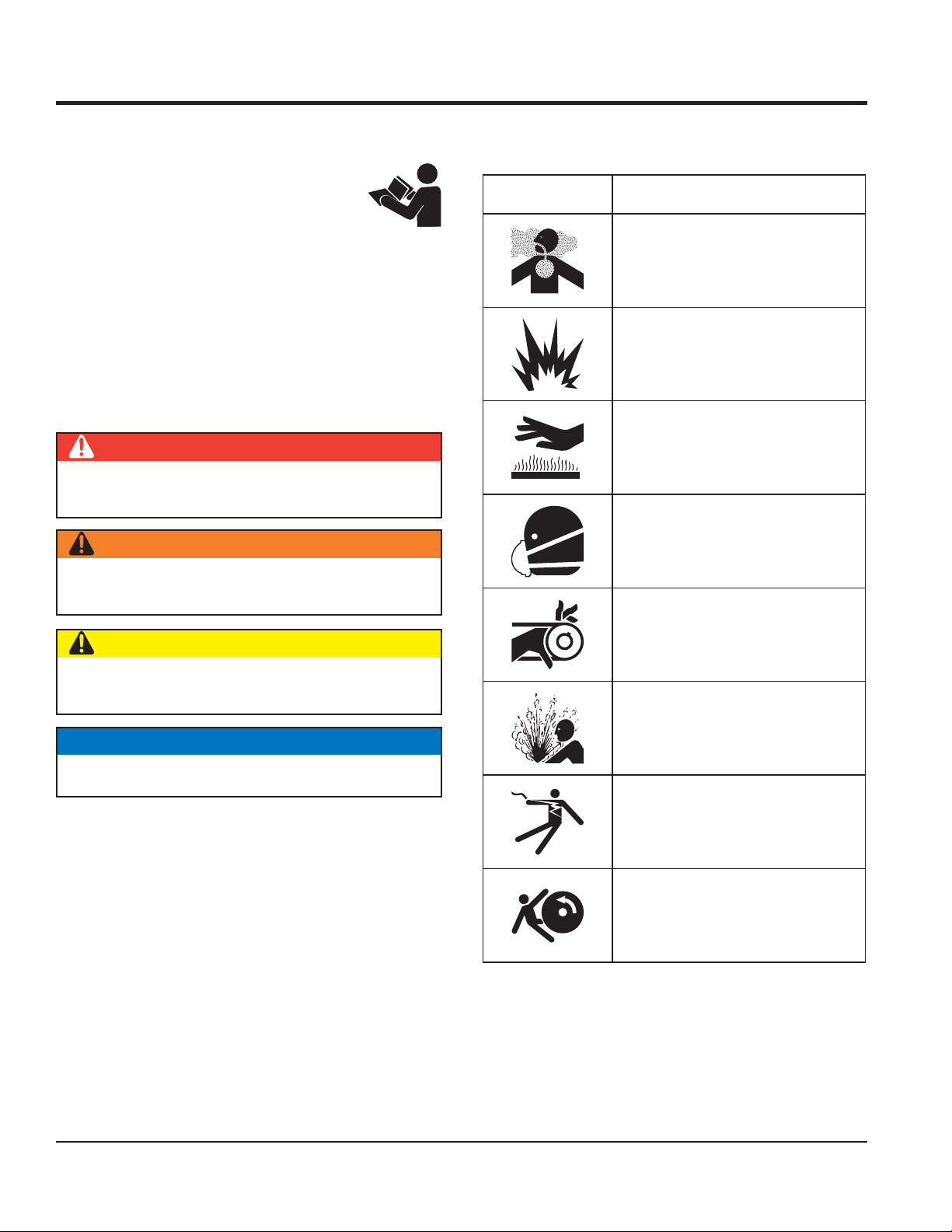
SAFETY SYMBOLS
DANGER
Indicates a hazardous situation which, if not avoided,
WILL result in DEATH or SERIOUS INJURY.
WARNING
The following table shows the potential hazards associated
with the operation of this equipment.
Symbol Safety Hazard
Lethal exhaust gas hazards
Explosive fuel hazards
Burn hazards
Respiratory hazards
Indicates a hazardous situation which, if not avoided,
COULD result in DEATH or SERIOUS INJURY.
CAUTION
Indicates a hazardous situation which, if not avoided,
COULD result in MINOR or MODERATE INJURY.
NOTICE
Addresses practices not related to personal injury.
Rotating parts hazards
Pressurized fluid hazards
Electric shock hazards
Runover hazards
PAGE 6 — MRH800DS2 VIBRATORY ROLLER • OPERATION AND PARTS MANUAL — REV. #1 (04/12/11)
Page 7
SAFETY INFORMATION
GENERAL SAFETY
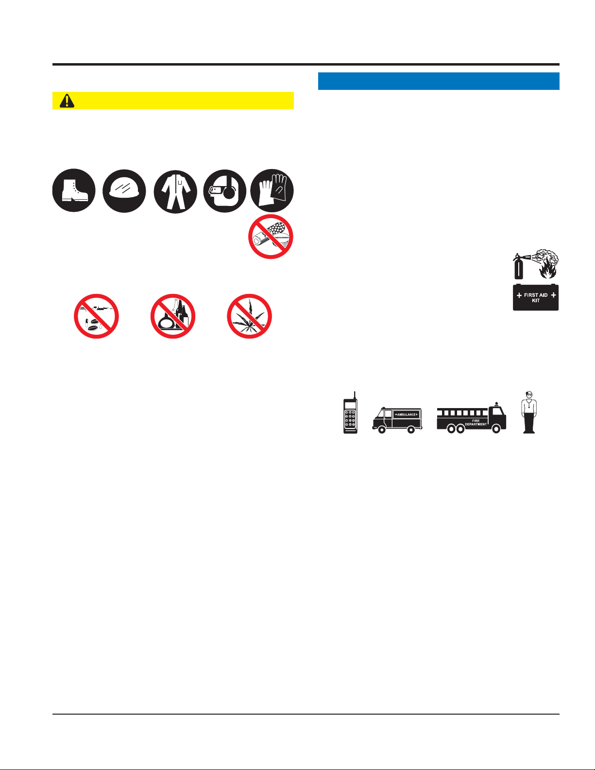
CAUTION
NEVER operate this equipment without proper protective
clothing, shatterproof glasses, respiratory protection,
hearing protection, steel-toed boots and other protective
devices required by the job or city and state regulations.
NEVER operate this equipment when not
feeling well due to fatigue, illness or when
under medication.
NEVER operate this equipment under the infl uence of
drugs or alcohol.
ALWAYS check the equipment for loosened threads or
bolts before starting.
DO NOT use the equipment for any purpose other than
its intended purposes or applications.
NOTICE
This equipment should only be operated by trained and
qualifi ed personnel 18 years of age and older.
Whenever necessary, replace nameplate, operation and
safety decals when they become diffi cult read.
Manufacturer does not assume responsibility for any
accident due to equipment modifi cations. Unauthorized
equipment modifi cation will void all warranties.
NEVER use accessories or attachments that are not
recommended by Multiquip for this equipment. Damage
to the equipment and/or injury to user may result.
ALWAYS know the location of the nearest
fi re extinguisher.
ALWAYS know the location of the nearest
fi rst aid kit.
ALWAYS know the location of the nearest phone or keep
a phone on the job site. Also, know the phone numbers
of the nearest ambulance, doctor and fi re department.
This information will be invaluable in the case of an
emergency.
ALWAYS clear the work area of any debris, tools, etc.
that would constitute a hazard while the equipment is
in operation.
MRH800DS2 VIBRATORY ROLLER • OPERATION AND PARTS MANUAL — REV. #1 (04/12/11) — PAGE 7
Page 8
SAFETY INFORMATION
ROLLER SAFETY
DANGER
NEVER operate the equipment in an explosive
atmosphere or near combustible materials. An
explosion or fi re could result causing severe
bodily harm or even death.
WARNING
NEVER disconnect any emergency or safety devices.
These devices are intended for operator safety.
Disconnection of these devices can cause severe injury,
bodily harm or even death. Disconnection of any of these
devices will void all warranties.
CAUTION
NEVER lubricate components or attempt service on a
running machine.
Never leave the roller unattended with the engine
running. Turn off engine.
DO NOT use worn-out hoses or couplings. Inspect daily.
ALWAYS store equipment properly when it is not being
used. Equipment should be stored in a clean, dry location
out of the reach of children and unauthorized personnel.
ENGINE SAFETY
DANGER
The engine fuel exhaust gases contain poisonous carbon
monoxide. This gas is colorless and odorless, and can
cause death if inhaled.
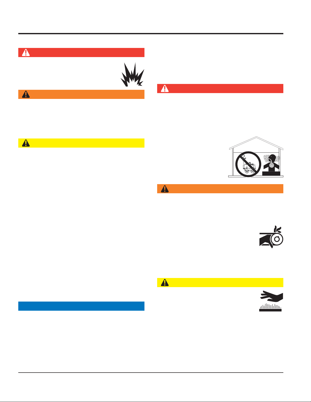
The engine of this equipment requires an adequate
free fl ow of cooling air. NEVER operate this equipment
in any enclosed or narrow
area where free fl ow of the
air is restricted. If the air
fl ow is restricted it will cause
injury to people and property
and serious damage to the
equipment or engine.
DANGEROUS
GAS FUMES
Use chock blocks when parking roller on a grade.
Use extreme care when operating near obstructions, on
slippery surfaces, grades, and slide slopes.
When reversing, particularly on the edges and banks
of ditches, as well as in front of obstaces, the operator
must stay in a standing position at a safe distance from
the machine.
When operating near any house/building or pipelines,
always check the effect of machine vibration. Stop work
if necessary.
DO NOT operate the roller with the covers open.
ALWAYS keep the machine away from other personnel
and obstacles. Always keep immediate are free of
bystanders.
NOTICE
ALWAYS keep the machine in proper running condition.
Fix damage to machine and replace any broken parts
immediately.
WARNING
DO NOT place hands or fingers inside engine
compartment when engine is running.
NEVER operate the engine with heat shields or
guards removed.
Keep fi ngers, hands hair and clothing away
from all moving parts to prevent injury.
DO NOT remove the engine oil drain plug
while the engine is hot. Hot oil will gush out of the oil
tank and severely scald any persons in the general area
of the roller.
CAUTION
NEVER touch the hot exhaust manifold,
muffl er or cylinder. Allow these parts to cool
before servicing equipment.
Always turn the engine off before performing maintenance.
PAGE 8 — MRH800DS2 VIBRATORY ROLLER • OPERATION AND PARTS MANUAL — REV. #1 (04/12/11)
Page 9
SAFETY INFORMATION
NOTICE
NEVER run engine without an air fi lter or with a dirty air
fi lter. Severe engine damage may occur. Service air fi lter
frequently to prevent engine malfunction.
NEVER tamper with the factory settings
of the engine or engine governor. Damage
to the engine or equipment can result
if operating in speed ranges above the
maximum allowable.
NEVER tip the engine to extreme angles during lifting as
it may cause oil to gravitate into the cylinder head, making
the engine start diffi cult.
FUEL SAFETY
DANGER
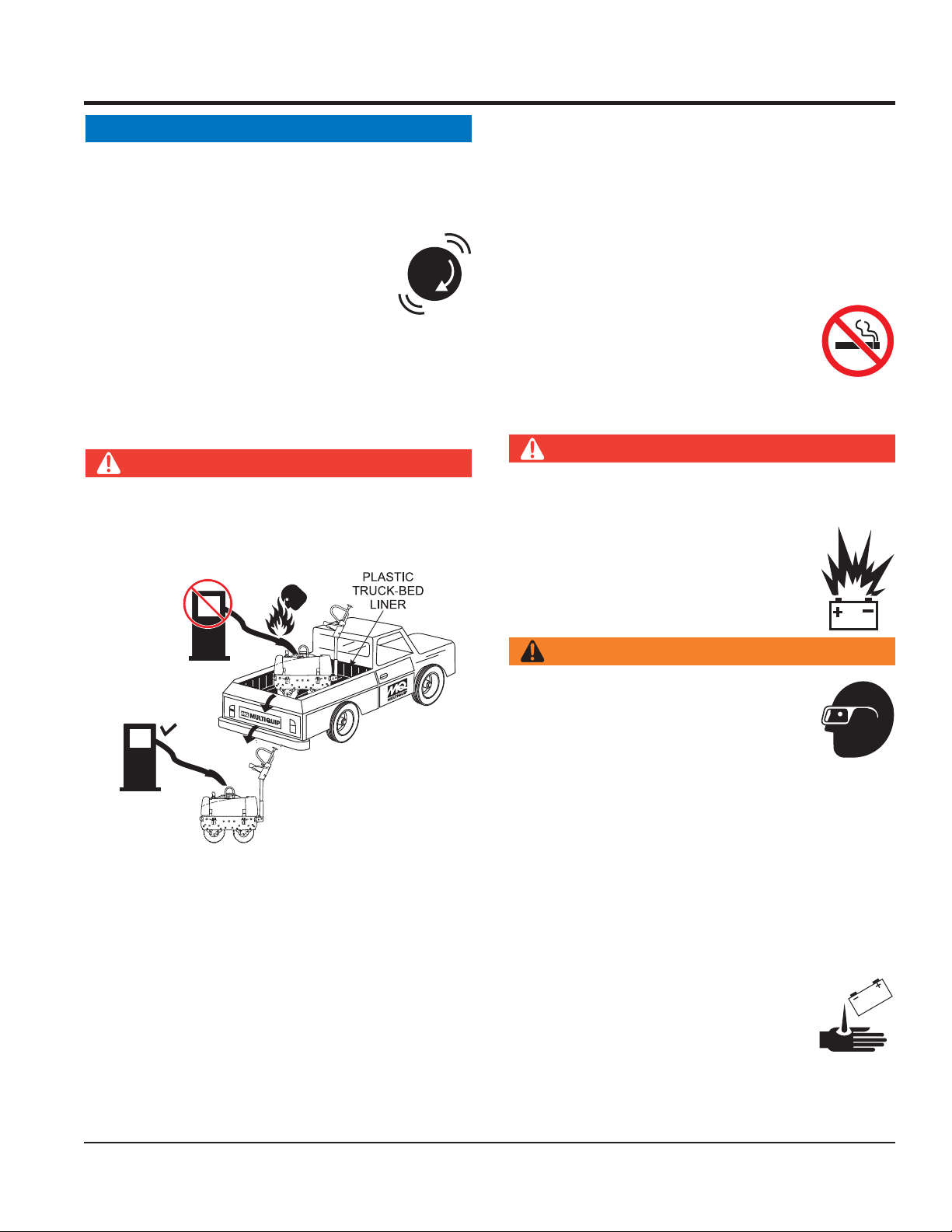
DO NOT add fuel to equipment if it is placed inside truck
bed with plastic liner. Possibility exists of explosion or
fi re due to static electricity.
FUEL
or hot.
DO NOT overfi ll tank, since spilled fuel could ignite if it
comes into contact with hot engine parts or sparks from
the ignition system.
Store fuel in appropriate containers, in well-ventilated
areas and away from sparks and fl ames.
NEVER use fuel as a cleaning agent.
DO NOT smoke around or near the
equipment. Fire or explosion could result
from fuel vapors or if fuel is spilled on a
hot engine.
BATTERY SAFETY (ELECTRIC START ONLY)
DANGER
DO NOT drop the battery. There is a possibility that the
battery will explode.
DO NOT expose the battery to open fl ames,
sparks, cigarettes, etc. The battery contains
combustible gases and liquids. If these
gases and liquids come into contact with a
fl ame or spark, an explosion could occur.
FUEL
DO NOT start the engine near spilled fuel or combustible
fl uids. Diesel fuel is extremely fl ammable and its vapors
can cause an explosion if ignited.
ALWAYS refuel in a well-ventilated area, away from
sparks and open fl ames.
ALWAYS use extreme caution when working with
fl ammable liquids.
DO NOT fi ll the fuel tank while the engine is running
WARNING
ALWAYS wear safety glasses when
handling the battery to avoid eye irritation.
The battery contains acids that can cause
injury to the eyes and skin.
Use well-insulated gloves when picking up
the battery.
ALWAYS keep the battery charged. If the battery is not
charged, combustible gas will build up.
DO NOT charge battery if frozen. Battery can explode.
When frozen, warm the battery to at least 61°F (16°C).
ALWAYS recharge the battery in a well-ventilated
environment to avoid the risk of a dangerous concentration
of combustible gases.
If the battery liquid (dilute sulfuric acid)
comes into contact with clothing or skin,
MRH800DS2 VIBRATORY ROLLER • OPERATION AND PARTS MANUAL — REV. #1 (04/12/11) — PAGE 9
Page 10

SAFETY INFORMATION
rinse skin or clothing immediately with plenty of water.
If the battery liquid (dilute sulfuric acid) comes into
contact with eyes, rinse eyes immediately with plenty
of water and contact the nearest doctor or hospital to
seek medical attention.
CAUTION
ALWAYS disconnect the NEGATIVE battery terminal
before performing service on the equipment.
ALWAYS keep battery cables in good working condition.
Repair or replace all worn cables.
TRANSPORTING SAFETY
CAUTION
NEVER allow any person or animal to stand underneath
the equipment while lifting.
NOTICE
Before lifting, make sure that the equipment parts are not
damaged and screws are not loose or missing.
transporting on a trailer. Make sure all supports attaching
the roller to the trailer are tight.
ENVIRONMENTAL SAFETY
NOTICE
Dispose of hazardous waste properly.
Examples of potentially hazardous waste
are used motor oil, fuel and fuel fi lters.
DO NOT use food or plastic containers to dispose of
hazardous waste.
DO NOT pour waste, oil or fuel directly onto the ground,
down a drain or into any water source.
Use lifting equipment capable of lifting the weight of
the roller.
Always make sure crane or lifi tng device has been
properly secured to the lifting bail (hook) of the
equipment.
ALWAYS shutdown engine before transporting.
NEVER lift the equipment while the engine is running.
Tighten fuel tank cap securely and close fuel cock to
prevent fuel from spilling.
Use adequate lifting cable (wire or rope) of suffi cient
strength.
Use one point suspension hook and lift straight upwards
with suffi cient bearing capacity to prevent machine from
tilting or slipping.
DO NOT lift machine to unnecessary heights.
ALWAYS make sure that roller is secured correctly when
PAGE 10 — MRH800DS2 VIBRATORY ROLLER • OPERATION AND PARTS MANUAL — REV. #1 (04/12/11)
Page 11

NOTES
MRH800DS2 VIBRATORY ROLLER • OPERATION AND PARTS MANUAL — REV. #1 (04/12/11) — PAGE 11
Page 12

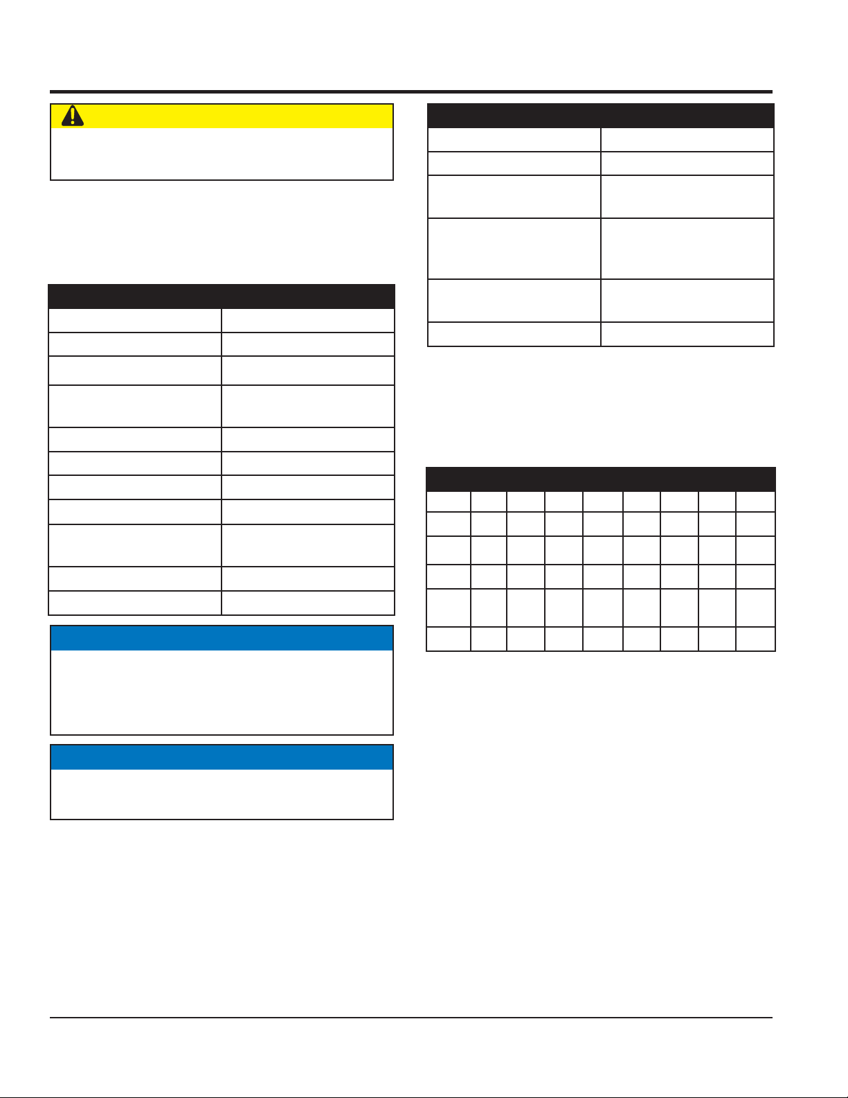
Table 1. Specifi cations (Vibratory Roller)
SPECIFICATIONS
Dimensions
Drum Diameter 16 in. (406 mm)
Drum Width 25.6 in. (650 mm)
Curb Clearance 9.6 in. (243 mm)
Side Overhang .83 in.(21 mm)
Operating Weight (with water) 1562 lbs. (710 kg)
Vibration Frequency 3,300 vpm
Centrifugal Force 23.5/2,400 kn/kgf
Drive System Hydraulic Motor
Vibration System Frame
Vibration Method Belt Drive
Vibrator Shaft Twin
Gradeablility 35 degrees
Working Speed 0 - 3 mph (0 - 4.8 kph)
Fuel Tank Capacity 1.88 gallons (7.1 liters)
Lubricating Oil 6.6 gallons (25 liters)
105 x 27.2 x 41.7 in
(2670 x 692 x 1060 mm)
Water Tank Capacity 10.57 gallons (40 liters)
Engine Model YANMAR Model L100V1AJ1R1AAMK
Starting System Electric/Recoil Start
PAGE 12 — MRH800DS2 VIBRATORY ROLLER • OPERATION AND PARTS MANUAL — REV. #1 (04/12/11)
Page 13
SPECIFICATIONS
Table 2. Specifi cations (Engine)
Engine Model YANMAR L100V1AJ1R1AAMK
Engine Type Air-cooled Diesel
Cylinder Bore X Stroke 3.4 x 2.95 in (86 x 75 mm)
Displacement 14.7 fl oz (435 cc)
Maximum Ouput 8.7 HP
Fuel Tank Capacity 5.6 quarts (5.4 liters)
Oil Capacity 1.7 quarts (1.6 liters)
Dry Net Weight 117.9 lbs. (54 kg)
Dimensions (L x W x H) 16.22 x 18.54 x 19.45 in (412 x 471 x 494 mm)
MRH800DS2 VIBRATORY ROLLER • OPERATION AND PARTS MANUAL — REV. #1 (04/12/11) — PAGE 13
Page 14
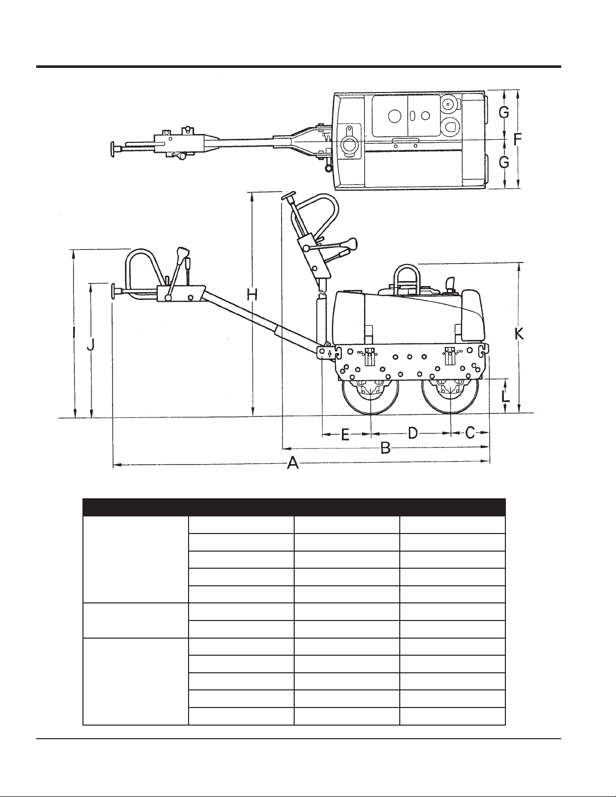
DIMENSIONS
Figure 1. MRH800DS2 Dimensions
Table 3. Dimensions
A 105 in. 2670 mm.
B 57 in. 1445 mm.
LENGTH
WIDTH
HEIGHT
PAGE 14 — MRH800DS2 VIBRATORY ROLLER • OPERATION AND PARTS MANUAL — REV. #1 (04/12/11)
C 10 in. 255 mm.
D 22.8 in. 580 mm.
E 13.8 in. 350 mm.
F 27.2 in. 692 mm.
G 13.6 in. 346 mm.
H 78.3 in. 1990 mm.
I 46.5 in. 1180 mm.
J 37.4 in. 950 mm.
K 41.7 in. 1060 mm.
L 9.6 in. 245 mm.
Page 15

The Mikasa Model MRH800DS2 is a powerful compacting
tool capable of applying tremendous force in consecutive
impacts to a soil surface. Its applications include soil
compacting for backfi lling for gas pipelines, water pipelines
and cable installation work.
The impact force of the MRH800DS2 levels and uniformly
compacts voids between soil particles to increase dry
density.
Features include:
Hydraulic transmission to allow speed change without
gear shifting.
Deadman device which when pressed or hit will cause
the travel lever to return to neutral position bringing the
machine to a stop.
A horn to warn of machine’s approach.
Non-corrosive water tank for the sprinkler system with
a capacity of more than 10 gallons.
GENERAL INFORMATION
Lifting hook to transport machine.
Front bumper and working light.
Narrow profi le with less than one inch wall clearance.
Narrower width allows access to tighter areas. No
exposed hydraulic hoses.
Oil bath lubricated bearings and external vibration for
less servicing and more dependability.
Front and rear drum scrapers.
Drum sprinkler system controls located near the operator.
Easy access to hydraulic components and hydraulic fi lter.
MRH800DS2 VIBRATORY ROLLER • OPERATION AND PARTS MANUAL — REV. #1 (04/12/11) — PAGE 15
Page 16
COMPONENTS
1
2
4
3
6
8
9
5
10
11
7
Figure 2. MRH800DS2 Components
PAGE 16 — MRH800DS2 VIBRATORY ROLLER • OPERATION AND PARTS MANUAL — REV. #1 (04/12/11)
Page 17

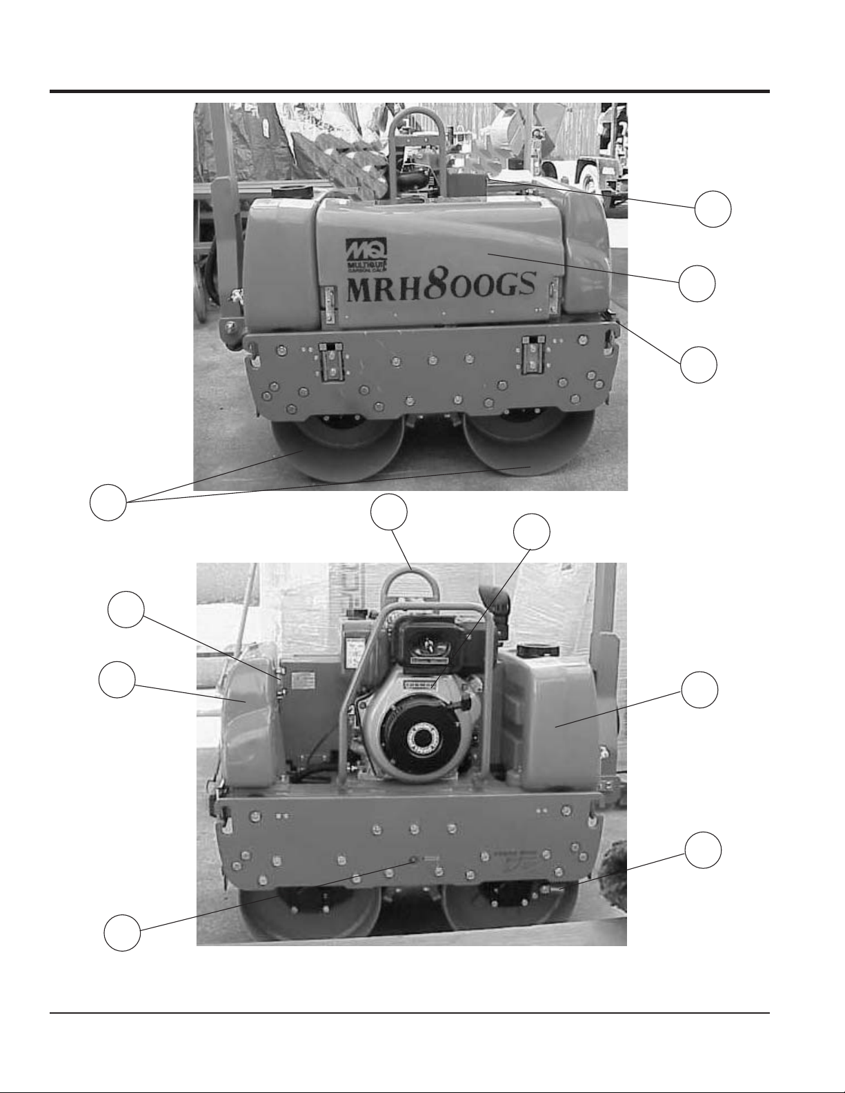
Figure 2 illustrates the location of the major components
for the MRH800DS2 Vibration Roller. The function of each
component is described below:
1. Fuel Tank/Cap — Fill with diesel fuel. Fuel tank holds
approximately 2 gallons (7.5 liters). DO NOT top off
fuel. Wipe up any spilled fuel immediately.
2. Center Cover — When opened and supported by strut,
provides access to oil pump and fi lter, battery, V-belt,
and clutch box.
3. Vibration Rollers — 25-inch wide steel drums that
provide compaction force in the compaction and
patching of asphalt type surfaces.
4. Front Headlights — Activate using switch on control
handle. Use to illuminate ground during nighttime or
low-light operating conditions.
5. Hydraulic Oil Gauge — Indicates the hydraulic oil
level.
COMPONENTS
6. Oil Tank — Fill with proper grade of hydraulic oil.
7. Vibrator Oil Level Plug — Remove to check vibrator
oil level.
8. Lifting Hook — Used to lift the machine with crane or
other lifting device.
9. Engine — This machine uses the Yanmar
L100V1AJ1R1AAMK engine. Refer to the engine
Owner’s Manual for more information.
10. Water Tank — Holds 10.57 gallons (40 liters) for the
sprinkler system.
11. Parking Brake — Makes sure machine will not
accidentally move when parked or not in use.
MRH800DS2 VIBRATORY ROLLER • OPERATION AND PARTS MANUAL — REV. #1 (04/12/11) — PAGE 17
Page 18
3
4
COMPONENTS
1
2
5
Figure 3. Handle Bar/Lever Components
PAGE 18 — MRH800DS2 VIBRATORY ROLLER • OPERATION AND PARTS MANUAL — REV. #1 (04/12/11)
6
Page 19

HANDLE BAR/LEVER COMPONENTS
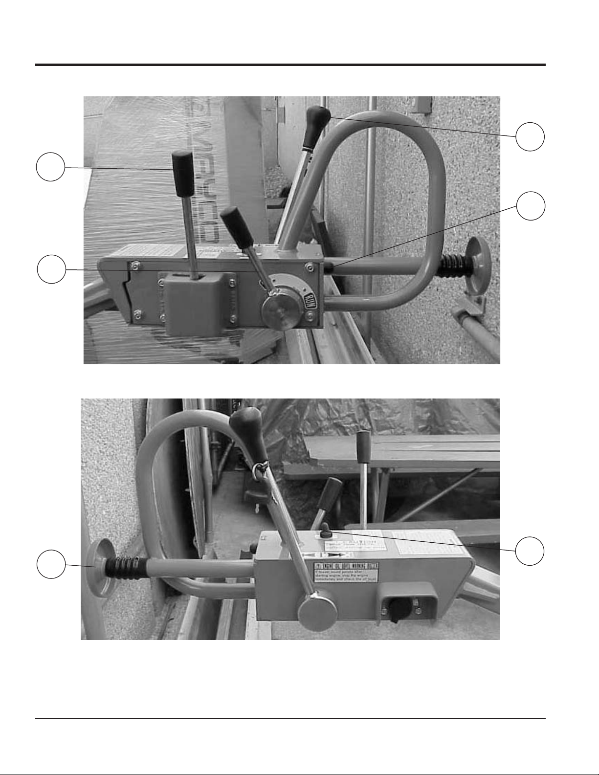
Figure 3 illustrates the location of the major lever
components on the handle bar of the machine. Each
component is described below:
1. Travel Lever — Controls the direction of travel of the
machine (forward and reverse).
2. Horn Button — When pressed, gives a warning sound
of the machine approaching.
3. Vibration Lever — Turns vibration on and off.
4. Throttle Lever — Controls the start up of the machine.
5. Dead-Man Device — When pressed or hit while
traveling in reverse, causes the travel lever to return
to neutral position to stop the machine.
6. Light ON/OFF Switch — Turns headlight on and off.
7. Starter Switch — Engine starts when key is turned
to the RUN position.
COMPONENTS
MRH800DS2 VIBRATORY ROLLER • OPERATION AND PARTS MANUAL — REV. #1 (04/12/11) — PAGE 19
Page 20
BASIC ENGINE
Figure 4. Yanmar Engine Components
ENGINE COMPONENTS
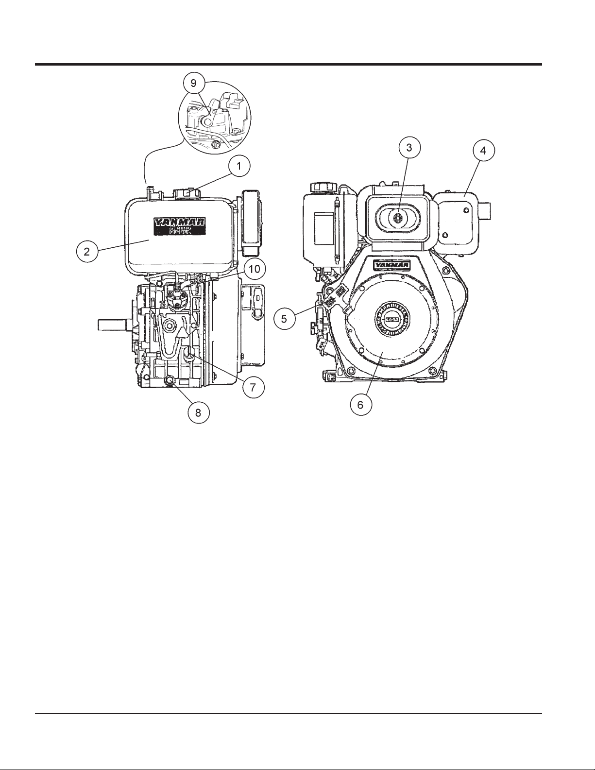
Figure 4 illustrates the location of the major engine
components. Each component is described below:
1. Fuel Filler Cap — Remove this cap to add unleaded
gasoline to the fuel tank. Make sure cap is tightened
securely. DO NOT over fi ll.
2. Fuel Tank — Diesel engine holds 5.7 quarts of diesel
fuel.
3. Air Cleaner — Prevents dirt and other debris from
entering the fuel system. Remove wing-nut on top of
air fi lter canister to gain access to fi lter element.
4. Muffl er — Used to reduce noise and emissions.
5. Recoil Starter (pull rope) — Type of engine starting
method. Alternate type would be electric start (ignition
key).
PAGE 20 — MRH800DS2 VIBRATORY ROLLER • OPERATION AND PARTS MANUAL — REV. #1 (04/12/11)
6. Recoil Starter — Housing for pull rope and starter.
7. Oil Filler Cap/Dipstick — Remove this cap to add oil
to the oil tank. Use dipstick to check oil level.
8. Oil Drain Plug — Unscrew plug to drain oil from engine
crankcase. Dispose of oil in a safe manner.
9. Decompression Lever — Press down before starting
engine. To prevent damage to the engine, DO NOT use
for any other purpose.
10. Fuel Cock — Controls the fl ow of diesel fuel to the
engine. Must be in the ON position when starting and
running the engine.
Page 21

NOTES
MRH800DS2 VIBRATORY ROLLER • OPERATION AND PARTS MANUAL — REV. #1 (04/12/11) — PAGE 21
Page 22
INSPECTION
BEFORE STARTING
1. Read safety information at the beginning of manual.
2. Remove dirt and dust, particularly in the engine cooling
air inlet, carburetor and air cleaner.
3. Check the air fi lter for dirt and dust. If air fi lter is dirty,
replace air fi lter with a new one.
4. Check carburetor for external dirt and dust. Clean with
dry compressed air.
5. Check fastening nuts and bolts for tightness.
6. Understand the geographical features and regulations
of the job site.
ENGINE OIL CHECK
1. To check the engine oil level, place the machine on
secure level ground with the engine stopped.
2. Remove the fi ller dipstick from the engine oil fi ller hole
(Figure 5) and wipe clean.
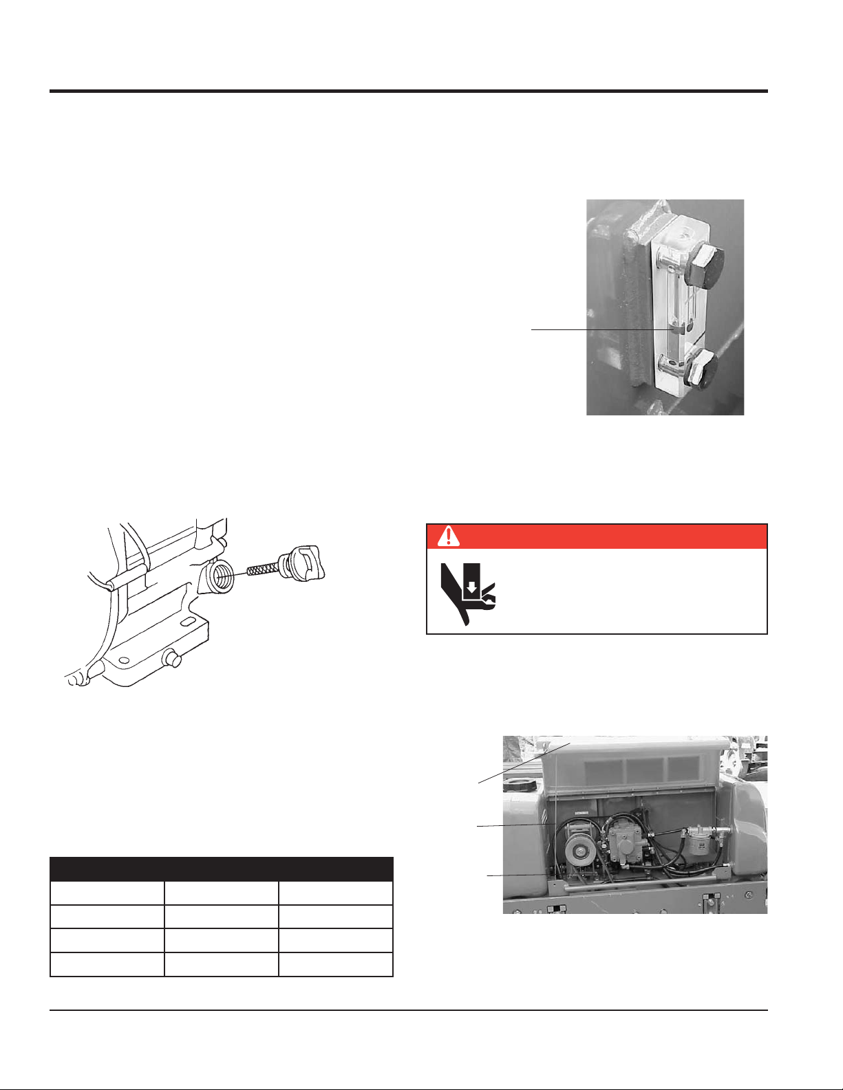
CHECKING THE HYDRAULIC SYSTEM
1. Check the oil tank level gauge (Figure 6). Oil level
should be at the middle indication of the gauge or
higher. Fill as required.
LEVELS SHOULD BE
MIDDLE OF GAUGE
OR HIGHER
Figure 6. Hydraulic System Oil Level Gauge
2. Check the surroundings of the oil tank, hydraulic pump
and motor for oil leakage.
CHECKING THE V-BELT
Figure 5. Engine Oil Level
3. Insert and remove the dipstick without screwing it into
the fi ller neck. Check the oil level shown on the dipstick.
4. If the oil level is low, fi ll to the edge of the oil fi ller hole
with the recommended oil type (Table 4). Maximum oil
capacity is 1.16 quarts (1.1 liters).
Table 4. Oil Type
Season Temperature Oil Type
Summer 25°C or Higher SAE 10W-30
DANGER
ALWAYS keep hands and fi ngers away
from pinch points. DO NOT allow anyone
to reach in on dangerous sections of the
machine to avoid any accidents.
1. Remove the 2 bolts, one on each side of the center
cover, with a #13 socket wrench. Open the center cover
of the machine and support it with the strut by inserting
its end to the hole in the base (Figure 7).
CENTER
COVER
STRUT
V-BELT
Spring/Fall 25°C~10°C SAE 10W-30/20
Winter 0°C or Lower SAE 10W-10
2. Check V-belt for proper tension. Insuffi cient tension
Figure 7. Checking V-Belt Tension
causes weak vibration.
PAGE 22 — MRH800DS2 VIBRATORY ROLLER • OPERATION AND PARTS MANUAL — REV. #1 (04/12/11)
Page 23
INSPECTION
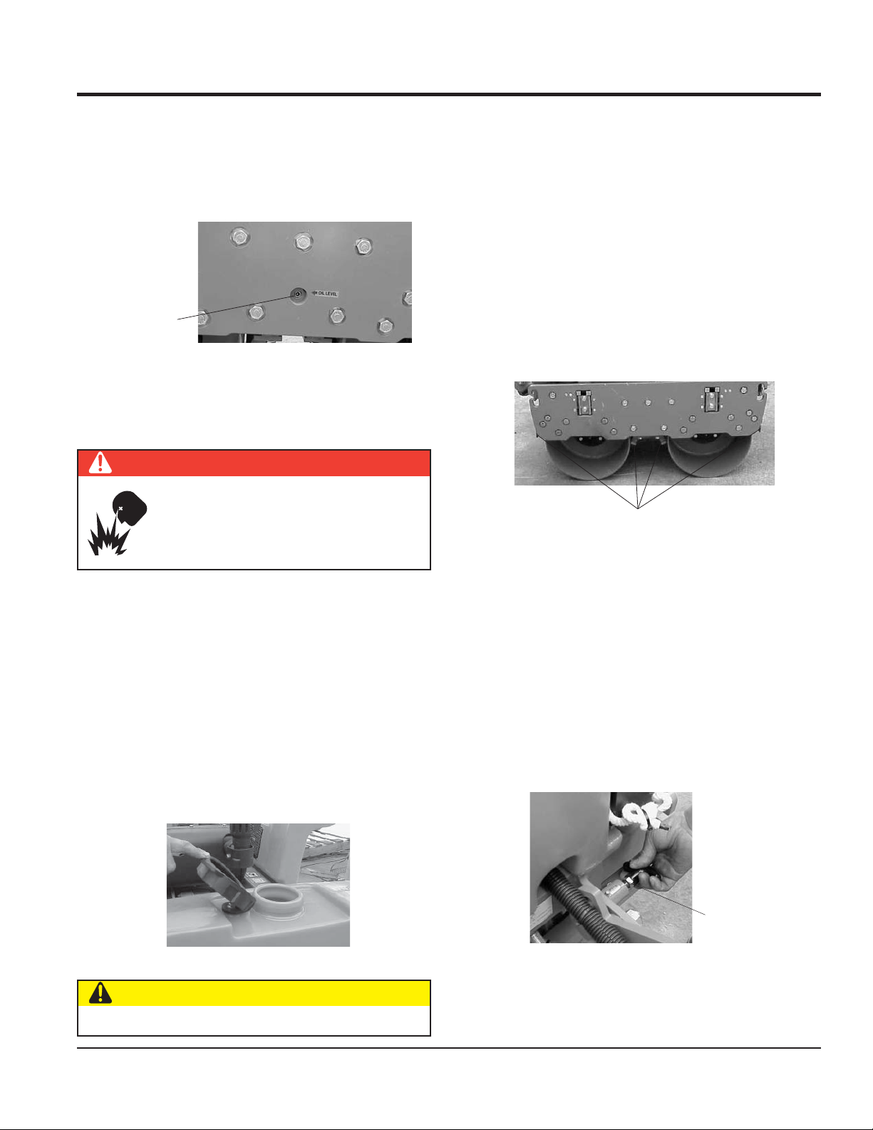
CHECKING THE VIBRATOR OIL LEVEL
1. Check vibrator casing for any oil leakage.
2. If any leakage is noticed, remove the level plug on the
side of the plate (Figure 8).
VIBRATOR OIL
LEVEL PLUG
Figure 8. Checking Vibrator Oil Level
3. Check the oil level.
FUEL CHECK
DANGER
Motor fuel is highly fl ammable and can be
dangerous if mishandled. DO NOT smoke
while refueling. DO NOT attempt to refuel
the pump if the engine is hot or running.
CHECKING LEVERS AND HORN
1. Check travel, vibration, and throttle levers to make sure
they are functioning properly (Figure 3).
2. With travel lever placed in reverse, push the deadman
device and verify that the travel lever returns to neutral
position. The travel lever stays in neutral position once
the deadman device is released.
3. Press the horn and verify that it functions properly.
CHECKING SCRAPERS
1. Check scrapers and make sure that they are not
clogged with mud, bent or damaged (Figure 10).
SCRAPERS
Figure 10. Checking Scrapers
1. Remove the fuel cap located on top of the engine fuel
tank.
2. Visually inspect to see if the fuel level is low. If fuel is
low, replenish with unleaded gasoline using a strainer
for fi ltration. DO NOT top-off fuel. Wipe up any spilled
fuel immediately!
CHECKING WATER TANK
Check the water tank to see if fi lled. Add water if necessary.
The water tank has a capacity of approximately 10 gallons
(40 liters). See Figure 9.
Figure 9. Checking Water Tank
2. Adjust clearance between drums and scrapers as
necessary.
CHECKING BOLTS, NUTS AND SCREWS
1. Check bolts, nuts, and screws on various parts of the
machine, including the engine, for proper tightness.
POSITIONING THE HANDLE BAR
1. Release the handle bar release pin (Figure 11) and
position the handle bar to the lowered position before
starting operation.
HANDLE BAR
RELEASE PIN
Figure 11. Positioning the Handle Bar
CAUTION
2. When machine is not in use, release the handle bar
release pin and position the handle bar to the upright
Be careful not to confuse the water tank with the oil tank.
position.
MRH800DS2 VIBRATORY ROLLER • OPERATION AND PARTS MANUAL — REV. #1 (04/12/11) — PAGE 23
Page 24

OPERATION
CAUTION
DO NOT attempt to operate the roller
until the Safety Information, General
Information, and Inspection sections of this
manual have been read and thoroughly
understood.
STARTING THE ENGINE
The engine can be started by motor (electric) or manually
(recoil). Refer to Figure 2 and Figure 3 for the location of
controls and components.
Electric Start
CAUTION
When the engine is running, never turn the starter key
to the START position
1. On the control handle:
a. Move the throttle lever to the RUN position.
b. Move the travel lever to the NEUTRAL position.
c. Move the vibration lever to the OFF position.
2. Open the fuel cock by turning it clockwise to the down
position (Figure 12).
4. Turn the starter key further to the right to the START
position (Figure 14) to start the engine. Buzzer stops
sounding when the engine speed increases. With safety
switch equipped, motor runs only when the travel lever
is in the neutral position.
Figure 14. Starter Key (Start Position)
5. If the engine fails to start, do not continue to rotate the
starter key for more than 5 seconds. Return the key
to the RUN position and wait 20 to 30 seconds before
starting again.
6. After starting the engine, continue to warm up the
engine for about 3 to 10 seconds especially in cold
weather.
7. If the buzzer does not stop sounding after the engine
has started, shutdown engine immediately and check
engine oil level. The buzzer functions as engine oil
level warning also.
RECOIL START
1. Move the throttle lever to the RUN position.
2. Open the fuel cock by turning it clockwise to the down
position (Figure 12).
3. Pull the starting handle slowly until you feel some
resistance (Figure 15). Return handle to original
FUEL COCK
(OPEN POSITION)
Figure 12. Open Fuel Cock
3. Insert the starter key into the key switch and turn it
to the RUN position (Figure 13). The buzzer should
sound at this time.
Figure 13. Starter Key (Run Position)
PAGE 24 — MRH800DS2 VIBRATORY ROLLER • OPERATION AND PARTS MANUAL — REV. #1 (04/12/11)
position.
PULL HANDLE
TO START
Figure 15. Engine Start Handle
Page 25
OPERATION
4. Push down the decompression lever (Figure 16).
Figure 16. Decompression lever
5. Pull the starting handle hard and fast to start engine
(Figure 15).
6. If the engine does not start, repeat steps 3 through 5.
NOTICE
When starting with a motor starter, a decompressor
is not normally required. However, when ambient
temperature or battery charger level is low, use of a
decompressor will help make the start-up easier.
TRAVELING
6. Push the travel lever backward to go in the reverse
direction.
CAUTION
Do not reduce speed during work. When shifting travel
lever from forward to reverse, be sure to stop the lever at
the neutral position fi rst before moving the lever to the
opposite direction. Do not shift the lever from forward to
reverse (or reverse to forward) in one motion.
CAUTION
After test travel, shut down engine and check for any
problems including oil leakage. If any trouble is found,
correct the problem before attempting to operate the
roller again.
VIBRATING
1. Shift the vibration lever away from its off position. The
vibration lever will automatically spring forward and the
roller will start vibrating (Figure 18).
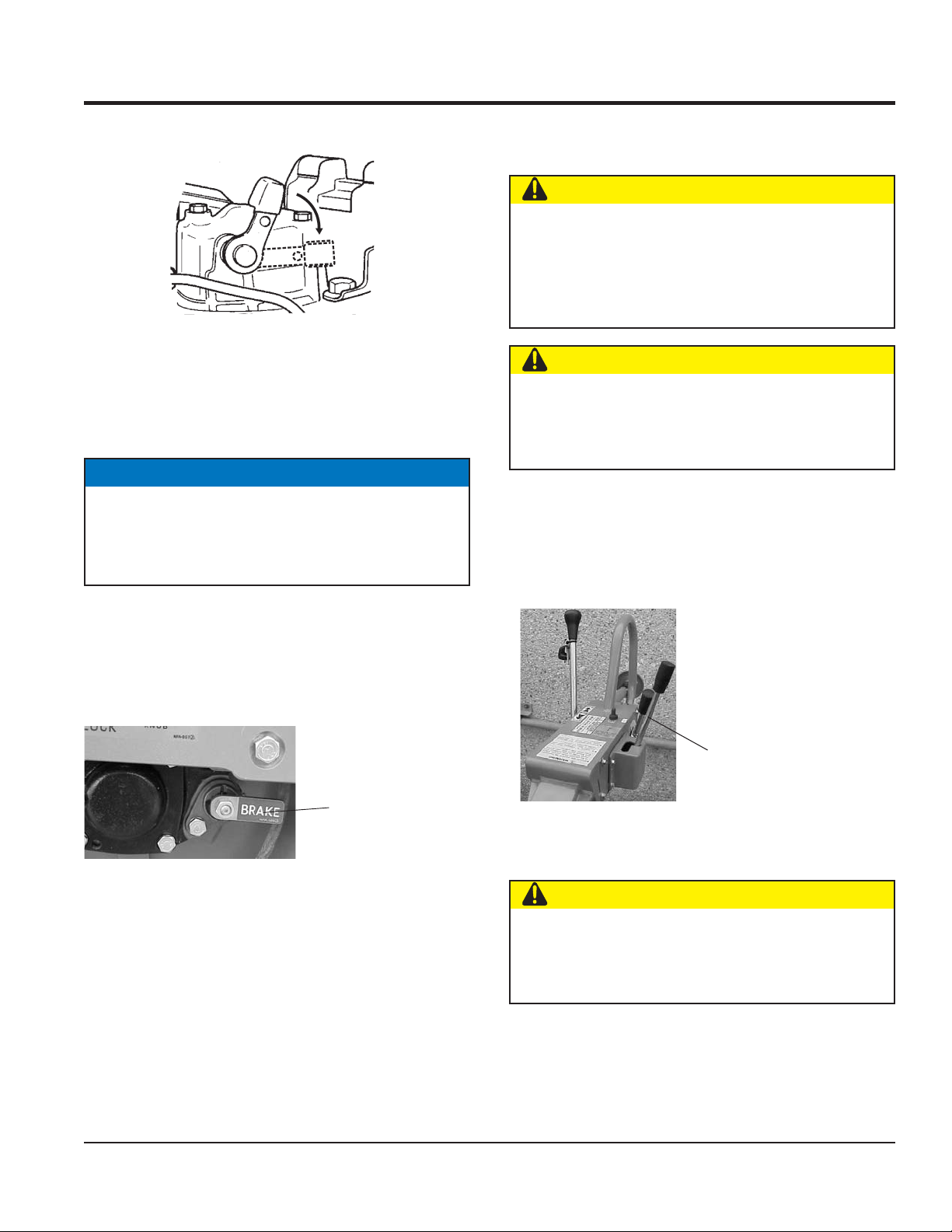
1. Before starting to travel, make sure to release parking
brake located on the left side of the rear roller. If the
parking brake lever is tight, moving the roller back and
forth will make it easier (Figure 17).
PARKING BRAKE
(RELEASED
POSITION)
Figure 17. Parking Brake
2. With the throttle lever in the RUN position, increase
the engine rotation.
3. Push the travel lever forward slightly. This will cause
the roller to travel forward at slow speed.
4. To increase the travel speed, push the travel lever
further.
5. Travel speed can be varied between 0 and 3 km/h
(both forward and reverse).
VIBRATION LEVER
(OFF POSITION)
Figure 18. Vibration Lever (Off Position)
CAUTION
Using vibration with clutch slipping causes the clutch to
burn. Also, vibration should not be used over completely
compacted area, paved road surface, or with stationary
roller.
MRH800DS2 VIBRATORY ROLLER • OPERATION AND PARTS MANUAL — REV. #1 (04/12/11) — PAGE 25
Page 26
OPERATION
WATERING
2. For watering work, turn the water cocks clockwise, at
the rear of the machine, to start sprinkling. (Figure 19).
WATER COCK
FOR FRONT DRUM
WATER COCK
FOR REAR DRUM
Figure 19. Water Cocks
SAFETY FEATURES
A horn is provided to warn of approach.
The dead man device prevents accidental traveling in
reverse. It automatically makes the travel lever return to
neutral position by stopping the machine when an object
comes in contact with the dead man device.
STOPPING
1. With travel lever in the neutral position, and the
vibration lever in the off position, return the throttle
lever to the START position. Allow the machine to cool
down for 3 to 5 minutes.
2. Push the throttle lever forward to stop the engine. In a
motor start, return the key switch to the STOP position
as soon as the engine stops.
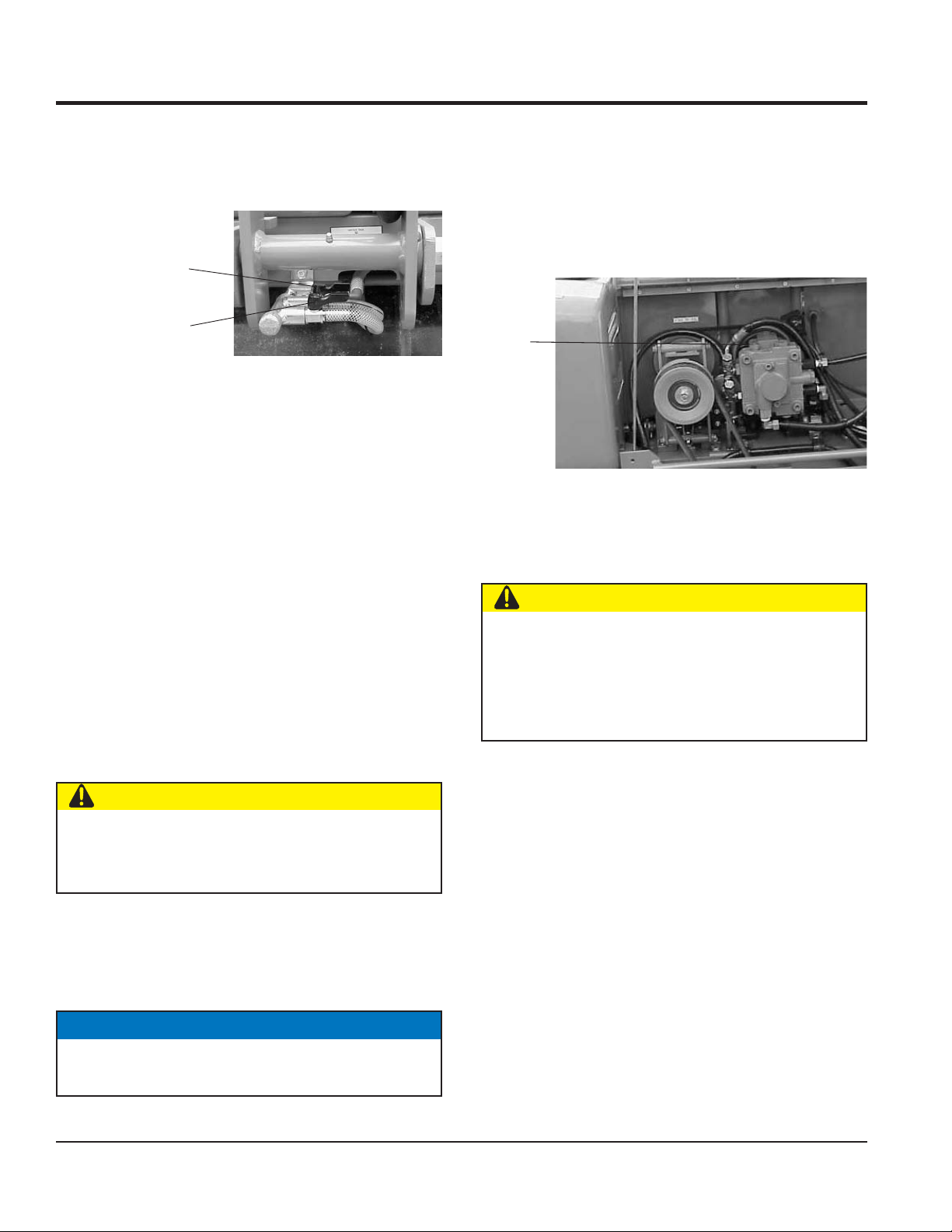
UNLOADING
5. If you need to move the roller by pushing it manually
once engine is stopped, loosen bolt of bypass valve
on oil pump by one rotation counterclockwise. This will
cause the hydraulic brake to disengage and allow the
roller to be moved more easily (Figure 20).
Bypass
Valve
Bolt
Figure 20. Location of Bypass Valve Bolt
6. After moving, tighten the bolt again. Tightening torque
is 55 to 70 kgf-cm.
CAUTION
NEVER tow roller with any type of vehicle. Doing so
will damage the hydraulic system.
Never perform unloading procedure on a slope. This
may cause roller to roll down if parking brake or blocking
is defi cient.
LIFTING
CAUTION
Neglecting to return the key switch to the STOP position
will cause the battery to discharge making start up
impossible the next time.
3. After the engine stops, close the fuel cock.
4. Lock the parking brake by pulling the brake lever and
rotating it 90° clockwise.
NOTICE
Parking brake system should always be kept clean to
avoid mud deposits.
PAGE 26 — MRH800DS2 VIBRATORY ROLLER • OPERATION AND PARTS MANUAL — REV. #1 (04/12/11)
1. Use a crane or lift to load and unload the machine. A
skilled crane operator is required to perform the job.
2. When lifting the machine, check for any damaged or
loose bolts, lifting hooks, and shock mounts.
3. Check any damaged or loose bolts in the guard frame
to avoid machine sliding off.
4. Make sure that the machine is shut off before machine
is lifted.
5. Use reliable cable for lifting.
6. Always lift the machine vertically and keep the machine
away from workers and animals.
7. Do not lift the machine higher than the required height.
Page 27
TRANSPORTING
1. Always make sure that the machine is shut off while
being transported.
2. Check that the fuel cap is properly closed and tightened.
3. When traveling long distances or on rugged terrain,
drain the fuel of the machine before transporting.
4. Tie down the machine securely on the transportation
so that it will not move or topple over.
CAUTION
Inspection and other services should always be carried
out on hard and level ground with the engine shutdown.
OPERATION
MRH800DS2 VIBRATORY ROLLER • OPERATION AND PARTS MANUAL — REV. #1 (04/12/11) — PAGE 27
Page 28
MAINTENANCE
CAUTION
Inspection and other services should always be carried
out on hard and level ground with the engine shutdown.
INSPECTION AND MAINTENANCE SERVICE TABLES
To make sure your vibratory roller is always in good
working condition before using, carry out the maintenance
inspection procedures.
Table 5. Machine Inspection
ITEM HOURS OF OPERATION
Loose or Missing Screws Every 8 hours (every day)
Damaged Parts Every 8 hours (every day)
Function of Controlling
System Part
Hydraulic System Leak Every 100 hours
Vibrator Oil Check Every 100 hours
Vibrator Oil Replacement Every 300 hours
Hydraulic Oil Check Every 100 hours
Hydraulic Oil Replacement
V-belt (clutch) Check Every 200 hours
Battery Check Every 100 hours
NOTICE
Every 8 hours (every day)
First after 200 hours, then
every 1,000 hours
Table 6. Engine Check
ITEM HOURS OF OPERATION
Oil or Fuel Leak Every 8 hours (every day)
Tightness of Fastening
Threads
Engine Oil Check and
Replenishment
Engine Oil Replacement
Every 8 hours (every day)
Every 8 hours (every day)
(Replenish to specifi ed
maximum level)
After fi rst 25 hours then
every 50 to 100 hours
Air Filter Cleaning Every 100 hours
DAILY SERVICE
1. Check for leakage of fuel or oil.
2. Check for loose screws including tightness. See Table
7 below (tightening torque ), for retightening:
Table 7. Tightening Torque (in. kg/cm) Diameter
Material
4T
6-8T
11T
*
6mm 8mm 10mm 12mm 14mm 16mm 18mm 20mm
70 150 300 500 750 1,100 1,400 2,000
100 250 500 800 1,300 2,000 2,700 3,800
150 400 800 1,200 2,000 2,900 4,200 5,600
300~
350
650 ~
700
100
These inspection intervals are for operation under
normal conditions. Adjust your inspection intervals
based on the number of hours the roller is in use, and
your particular working conditions.
NOTICE
3. Remove soil and clean the bottom of roller.
4. Check hydraulic pump, piping and hose for any leakage.
5. A loosened hydraulic hose can be a cause for leakage.
Check hydraulic hose connections with wrench applied
for tightness.
Fuel piping and connections should be replaced every
2 years.
6. Check engine oil.
ENGINE OIL REPLACEMENT:
1. Replace engine oil in the fi rst 25 hours of operation
and every 50 to 100 hours afterwards.
2. Oil may be drained more easily when it is warm after
operation (For more details, see separate engine
Owner's Manual).
PAGE 28 — MRH800DS2 VIBRATORY ROLLER • OPERATION AND PARTS MANUAL — REV. #1 (04/12/11)
Page 29

MAINTENANCE
AIR FILTER
1. The air fi lter element should be cleaned because a
clogged air cleaner can cause poor engine starting,
lack of power and shorten engine life substantially.
2. To clean or replace air fi lter loosen the wing nut on the
air fi lter housing (Figure 21) remove the cover and take
out air fi lter cartridge. If only cleaning of the air fi lter
is desired blow through the air fi lter cartridge from the
inside, moving a jet of dry compressed air up and down
until all dust is removed.
Figure 21. Engine Air Filter and Element
VIBRATION CLUTCH ADJUSTMENT
1. Move vibration lever to the OFF position.
2. Loosen the front and rear nuts at the end of vibration
clutch cable (Figure 22).
CAUTION
CLUTCH
PULLEY
NEVER attempt to check the V-belt
with the engine running. Severe injury
can occur if your hand gets caught
between the V-belt and the clutch.
VIBRATOR
PULLEY
Always use safety gloves.
CAUTION
Excessive turning of front nut may cause the sliding
engagement of clutch to take place or no vibration takes
place even when vibration lever is engaged.
On the other hand, insuffi cient turn may cause sliding
engagement of clutch even when the vibration lever is
placed in the OFF position or for vibration to remain
engaged.
HYDRAULIC SYSTEM INSPECTION AND SERVICE
1. Check motor and pump for any damage.
2. Check hoses and pipes for proper tightness and make
sure there are no leaks.
3. Check nylon tubes for hydraulic oil intake and drain.
Retighten brass nut if loose and if a leak is detected.
If leak continues after retightening, replace nylon tube,
nut and sleeve.
4. Check oil tank for proper oil level using the hydraulic
system oil level gauge (See Figure 6). Make sure
hydraulic oil has not whitened or emulsifi ed. Whitish
REAR NUT
color means aeration in pump. Retighten pipe and
correct level of oil. Emulsifi cation means water in the
FORK
FRONT NUT
hydraulic oil. Replace the oil.
ROLLER INSPECTION AND ADJUSTMENT
1. Refer to Table 8 for oil and grease requirements.
2. Check oil tank level daily.
Figure 22. Vibration Clutch Adjustment
3. Check the machine for oil leak and proper function of
3. Turn in the nut on the front side again and at the position
lever, cables, and links daily.
that release fork starts to move, turn in the nut by one
or two threads. Lock it a this position together with the
rear nut.
MRH800DS2 VIBRATORY ROLLER • OPERATION AND PARTS MANUAL — REV. #1 (04/12/11) — PAGE 29
Page 30

MAINTENANCE
MACHINE MAINTENANCE
1. At the end of each day’s operation, wash down dust
and dirt off the machine. Clean area around drums ad
scrapers making sure all mud is removed.
2. Drain water tank completely.
3. Cover the machine to prevent dust and store in dry
place away from sun exposure.
LONG TERM STORAGE
1. Conduct thorough lubrication and oil change.
2. Disconnect battery terminals and dismount battery
from machine. Store battery.
3. If there a possibility that ambient temperature will drop
below freezing point, add antifreeze agent to coolant.
4. Cover the inlet and outlet of air cleaner and muffl er
securely.
5. Store machine indoors. Do not leave outdoors.
• completely charged: 1.270 - 1.290
• needs charging: 1.260 or lower.
7. If the machine will not be in operation for a long period
of time, charge the battery suffi ciently, tighten all caps
correctly, store in cool dry place and check the battery
charge level every month to maintain the performance
of the battery.
BATTERY CABLE CONNECTION
1. When removing cable, disconnect the ground side
(normally negative) fi rst (Figure 23).
NEGATIVE
TERMINAL
Figure 23. Battery Connection
POSITIVE
TERMINAL
FORWARD AND REVERSE TRAVEL ADJUSTMENT
6. Refer to Table 8 for lubrication necessary for the
machine.
BATTERY MAINTENANCE
NOTICE
Read and understand the battery safety information in
the front of this manual before performing maintenance
on the battery.
1. Use a fl ashlight to check battery electrolyte level.
Always check that the engine is stopped.
2. If a battery has not been used for some time, reduce
the charge level initially to protect each plate inside
the battery.
3. Check the battery terminals periodically to ensure that
they are in good condition.
4. Use wire brush or sand paper to clean the battery
terminals.
5. Check battery for cracks or any other damage. If
white pattern appears inside the battery or paste has
accumulated at the bottom, replace the battery.
6. Measure the specifi c gravity of electrolyte:
2. If neutral position for forward and reverse travel has
been displaced, conduct the neutral adjustment.
3. If roller travels forward with the ball of ball plunger
remaining in V slot of the guide, loosen M8 bolt and
slide the slide plate slightly toward the engine. If the
roller travels backward, slide the plate towards side
plate (Figure 24).
PLUNGER
M8 BOLT
Figure 24. Adjustment of Neutral Position
4. When installing cable, connect the ground side
(normally negative) last.
5. With M8 bolt tightened, start engine and check the
neutral for forward and reverse. If still displaced, repeat
the procedure.
6. If neutral position of forward/reverse lever has been
displaced, use the turn buckle located on the oil pump
side of forward/reverse cable.
GUIDE
SIDE PLATE
PAGE 30 — MRH800DS2 VIBRATORY ROLLER • OPERATION AND PARTS MANUAL — REV. #1 (04/12/11)
Page 31

Table 8. Lubrication Chart
MAINTENANCE
ITEM
Vibrator Oil Replace Oil
Engine Oil Replace Oil
Hydraulic Oil Replace Oil
Travel Lever, Vibration
Lever, Throttle Lever
MAINTENANCE
NEEDED
Add Lubrication Oil to
Sliding Parts
FREQUENCY TYPE LOCATION
Every 300 Hours of
Operation
Initially - After 10
to 20 Hours of
Operation
Thereafter - Every
50 to 100 Hours of
Operation
Every 1000 to 1500
Hours of Operation
Every 50 Hours of
Operation
SAE10W30 (1.5 liters) see Figure 25
SAE#30 or SAE10W30
(Spring - Summer)
SAE#20 or SAE10W30
(Fall - Winter)
SAE10W30
(Extremely Cold Region)
Viscosity:
ISO VG32 equivalent for cold region
ISO VG46 or 56
equivalent - for warm
region
Shipped from factory
with Shell Tellus 46
(25 liters)
Lubrication Oil see Figure 3
see Figure 5
see Figure 6
Dead Man's Device
Handle Bar Release
Pin
Bearing Cover
Clutch Box
Travel Lever
Oil Filter Replace Oil Filter
Lubricate Grease
Fitting
Lubricate Grease
Fitting
Lubricate Grease
Fitting
Lubricate Grease
Fitting
Lubricate Sliding
Parts
Every 50 Hours of
Operation
Every 50 Hours of
Operation
Every 50 Hours of
Operation
Every 50 Hours of
Operation
Every 50 Hours of
Operation
Initially - After 25
Hours of Operation
Thereafter - Every
500 Hours of
Operation
Grease see Figure 3
Grease see Figure 27
Grease see Figure 26
Grease see Figure 28
Grease see Figure 3
Mikasa Genuine 10
micron Filter Paper
see Figure 29
MRH800DS2 VIBRATORY ROLLER • OPERATION AND PARTS MANUAL — REV. #1 (04/12/11) — PAGE 31
Page 32

VIBRATOR OIL
LEVEL PLUG
VIBRATOR OIL
DRAIN PLUG
Figure 25. Vibrator Oil Maintenance
MAINTENANCE
HANDLE BAR RELEASE
PIN GREASE FITTING
Figure 27. Handle Bar Maintenance
CLUTCH BOX
BEARING COVER
GREASE FITTING
Figure 28. Clutch Box Maintenance
BEARING COVER
GREASE FITTING
Figure 26. Bearing Cover Maintenance
PAGE 32 — MRH800DS2 VIBRATORY ROLLER • OPERATION AND PARTS MANUAL — REV. #1 (04/12/11)
Figure 29. Hydraulic Oil Filter Location
GREASE FITTING
HYDRAULIC OIL FILTER
Page 33

TROUBLESHOOTING
Troubleshooting - Roller
SYMPTOM POSSIBLE PROBLEM SOLUTION
Unit does not travel. Parking brake still engaged? Release parking brake lever.
Defective centrifugal clutch? Repair or replace clutch.
Damaged rubber coupling and fl ange? Replace rubber coupling and fl ange.
Defective travel cable and link? Repair or replace travel cable and link.
Unit does not travel or
travel is not smooth.
Unit does not vibrate
or has weak vibration.
Damaged scraper or too much mud in
scraper?
Damaged or clogged oil fi lter? Replace fi lter.
Damaged or leaking hydraulic pipe? Repair or replace parts.
Low oil level or contaminated oil? Replenish or replace oil.
Damaged or leaking hydraulic pump? Repair or replace hydraulic pump.
Damaged or leaking hydraulic motor? Repair or replace hydraulic motor.
Damaged drum gear and bearing? Repair parts.
Bad drum rotation? Repair or replace drum.
Defective centrifugal clutch? Repair or replace clutch.
Damaged or slipping V-belt? Replace V-belt or adjust tension.
Damaged vibration cable and linkage? Replace or repair vibration cable and linkage.
Damaged vibration clutch? Adjust or replace clutch.
Defective clutch vibrator pulley V-belt? Replace V-belt.
Vibrator does not turn smoothly with hand?
Replace or repair scraper.
Check and repair vibrator. Check if oil level is
not excessively high.
MRH800DS2 VIBRATORY ROLLER • OPERATION AND PARTS MANUAL — REV. #1 (04/12/11) — PAGE 33
Page 34

Symptom Possible Problem Solution
Engine will not start or start is delayed,
although engine can be turned over.
At low temperatures engine will not start.
Engine fi res but stops soon as starter is
switched off.
Engine stops by itself during normal
operation.
Low engine power, output and speed.
TROUBLESHOOTING
Troubleshooting (Engine)
No Fuel reaching injection pump? Add fuel. Check entire fuel system.
Defective fuel pump? Replace fuel pump.
Fuel fi lter clogged? Replace fuel fi lter and clean tank.
Faulty fuel supply line? Replace or repair fuel line.
Compression too low?
Fuel pump not working correctly? Repair or replace fuel pump.
Oil pressure too low? Check engine oil pressure.
Low starting temperature limit exceeded?
Defective battery? Charge or replace battery.
Air or water mixed in fuel system?
Engine oil too thick?
Defective battery? Replace battery.
Fuel fi lter blocked? Replace fuel fi lter.
Fuel supply blocked? Check the entire fuel system.
Defective fuel pump? Replace fuel pump.
Fuel tank empty? Add fuel.
Fuel fi lter blocked? Replace fuel fi lter.
Defective fuel pump? Replace fuel pump.
Mechanical oil pressure shutdown sensor
stops the engine due to low oil?
Fuel tank empty? Replace fuel fi lter.
Fuel fi lter clogged? Replace fuel fi lter.
Fuel tank venting is inadequate? Ensure that tank is adequately vented.
Leaks at pipe unions?
Speed control lever does not remain in
selected position?
Engine oil level too full? Correct engine oil level.
Injection pump wear?
Check piston, cylinder and valves. Adjust or
repair per engine repair manual.
Comply with cold starting instructions and
proper oil viscosity.
Check carefully for loosened fuel line
coupling, loose cap nut, etc.
Refi ll engine crankcase with correct type of
oil for winter environment.
Add oil. Replace low oil shutdown sensor if
necessary.
Check threaded pipe unions tape and tighten
unions a required.
See engine manual for corrective action.
Use No. 2-D diesel fuel only. Check the fuel
injection pump element and delivery valve
assembly and replace as necessary.
PAGE 34 — MRH800DS2 VIBRATORY ROLLER • OPERATION AND PARTS MANUAL — REV. #1 (04/12/11)
Page 35

Symptom Possible Problem Solution
Low engine power output and low speed,
black exhaust smoke.
Engine overheats.
TROUBLESHOOTING
Troubleshooting (Engine) - continued
Air fi lter blocked? Clean or replace air fi lter.
Incorrect valve clearances? Adjust valves per engine specifi cation.
Malfunction at injector? See engine manual.
Too much oil in engine crankcase?
Entire cooling air system contaminated/
blocked?
Fan belt broken or elongated? Change belt or adjust belt tension.
Coolant insuffi cient? Replenish coolant.
Radiator net or radiator fi n clogged with dust? Clean net or fi n carefully.
Fan, radiator, or radiator cap defective? Replace defective part.
Thermostat defective? Check thermostat and replace if necessary.
Head gasket defective or water leakage? Replace parts.
Drain off engine oil down to uppermark on
dipstick.
Clean cooling air system and cooling fi n
areas.
MRH800DS2 VIBRATORY ROLLER • OPERATION AND PARTS MANUAL — REV. #1 (04/12/11) — PAGE 35
Page 36

EXPLANATION OF CODE IN REMARKS COLUMN
”
The following section explains the different symbols and
remarks used in the Parts section of this manual. Use the
help numbers found on the back page of the manual if there
are any questions.
NOTICE
The contents and part numbers listed in the parts
section are subject to change without notice. Multiquip
does not guarantee the availability of the parts listed.
SAMPLE PARTS LIST
NO. PART NO. PART NAME QTY. REMARKS
1 12345 BOLT .....................1 .....INCLUDES ITEMS W/%
2% WASHER, 1/4 IN. ..........NOT SOLD SEPARATELY
2% 12347 WASHER, 3/8 IN. ..1 .....MQ-45T ONLY
3 12348 HOSE ..................A/R ...MAKE LOCALLY
4 12349 BEARING ..............1 .....S/N 2345B AND ABOVE
NO. Column
Unique Symbols — All items with same unique
symbol
QTY. Column
Numbers Used — Item quantity can be indicated by a
number, a blank entry, or A/R.
A/R (As Required) is generally used for hoses or other
parts that are sold in bulk and cut to length.
A blank entry generally indicates that the item is not sold
separately. Other entries will be clarifi ed in the “Remarks
Column.
REMARKS Column
Some of the most common notes found in the “Remarks”
Column are listed below. Other additional notes needed
to describe the item can also be shown.
Assembly/Kit — All items on the parts list with the
same unique symbol will be included when this item is
purchased.
Indicated by:
“INCLUDES ITEMS W/(unique symbol)”
(@, #, +, %, or >) in the number column belong to the
same assembly or kit, which is indicated by a note in the
“Remarks” column.
Duplicate Item Numbers — Duplicate numbers indicate
multiple part numbers, which are in effect for the same
general item, such as different size saw blade guards in
use or a part that has been updated on newer versions
of the same machine.
NOTICE
When ordering a part that has more than one item
number listed, check the remarks column for help in
determining the proper part to order.
PART NO. Column
Numbers Used — Part numbers can be indicated by a
number, a blank entry, or TBD.
TBD (To Be Determined) is generally used to show a
part that has not been assigned a formal part number
at the time of publication.
A blank entry generally indicates that the item is not sold
separately or is not sold by Multiquip. Other entries will
be clarifi ed in the “Remarks” Column.
Serial Number Break — Used to list an effective serial
number range where a particular part is used.
Indicated by:
“S/N XXXXX AND BELOW”
“S/N XXXX AND ABOVE”
“S/N XXXX TO S/N XXX”
Specifi c Model Number Use — Indicates that the part
is used only with the specifi c model number or model
number variant listed. It can also be used to show a
part is NOT used on a specifi c model or model number
variant.
Indicated by:
“XXXXX ONLY”
“NOT USED ON XXXX”
“Make/Obtain Locally” — Indicates that the part can
be purchased at any hardware shop or made out of
available items. Examples include battery cables, shims,
and certain washers and nuts.
“Not Sold Separately” — Indicates that an item cannot
be purchased as a separate item and is either part of an
assembly/kit that can be purchased, or is not available
for sale through Multiquip.
PAGE 36 — MRH800DS2 VIBRATORY ROLLER • OPERATION AND PARTS MANUAL — REV. #1 (04/12/11)
Page 37

SUGGESTED SPARE PARTS
MRH800DS2 VIBRATORY ROLLER WITH YANMAR L100V1AJ1R1AAMK DIESEL ENGINE
1 to 3 units
Qty. P/N Description
1............954407840 ............FILTER, WATER TANK
2............954001380 ............FILTER, HYDRAULIC OIL
2............070503000 ............V-BELT, ENGINE
1............956100022 ............THROTTLE WIRE
1............954300342 ............CAP, WATER TANK
2............070100381 ............V-BELT, VIBRATOR ASSY.
1............71421053100 ........VALVE ASSY., FUEL INJECTOR
1............71434951400 ........PUMP ASSY., FUEL INJECTOR
3............11421012590 ........ELEMENT, AIR CLEANER
1............11428855041 ........CAP ASSY., FUEL TANK
2............11429935110 ........STRAINER, LUB. OIL ASSY.
1............11429955100 ........FILTER, FUEL STRAINER
2............11425055121 ........FILTER, FUEL OIL
2............955000010 ............KEY, STARTING
NOTICE
Part numbers on this Suggested Spare Parts list may
supersede/replace the part numbers shown in the
following parts lists.
MRH800DS2 VIBRATORY ROLLER • OPERATION AND PARTS MANUAL — REV. #1 (04/12/11) — PAGE 37
Page 38

NAMEPLATES AND DECALS
CARSON, CALIF.
CAUTION
CAUTION
TO OPERATEWITHOUT
VIBRATION KEEPTHE
LEVER AT
OFF POSITION.
WARNING
CAUTION
25
HORN
N
NPA-537
7
REVERSE
2
SET ENGINE SPEED at
2,450-2,500 R.P.M.
Without vibration for this roller.
Do not set the engine speed not more than
2,500 rpm (revolution per minute), which may
cause the machine damage.
The set engine speed makes this roller the
ideal vibration speed of 3,300 vpm
(vibration per minute).
23
L
E
G
H
N
NP-517
STOP
CAUTION
N
NP-517
28
4
8
18
NPA-249
J
CAUTION
TO OPERATEWITHOUT
VIBRATION KEEPTHE
LEVER AT OFF POSITION.
NPA-281
32
FORWARD
CAUTION
BEFORE ENGINE STARTING
Travel lever should be in neutral position.
BEFORE TRAVELING THE ROLLER
Parking break should be disengaged
IN COLD SEASON FOR HOUSING, DRAIN FROM
WATERTANK AND HOSES TO PREVENT FREEZING
J
NPA-966 YS
35
12
Shouldthe machine be necessary
tobe parked on an incline, place
travellever in stop position first
andblock front and rear drums.
Thenstop the engine.
Ifengine is stopped, first the
machinemay roll on incline and
N
causedamage or injury
Wheneverparking the machine,
keeptravel lever in the stop
position.
26
22
J
NPA-564
19
11
CARSON, CALIF.
3
3
3
J
13
-
A
P
N
OWNER’S MANUAL
29
30
15
WATER TANK
1
16
MRH 00DS8
17
READ
NPA-629
21
CAUTION
1 Do not operate this roller unless you have finished special training its
itsoperation.
2 Read Operation Manual thoroughly before operating the machine.
3 Wear necessary protectors and proper work clothes.
4 When refueling, stop the engine and allow it to cool.
5 Start and operate only in well-ventillated area.
Breathingexhaust fumes can result in sickness or death.
6 Keep travel lever in neutral and vibration lever in the OFF position,
thenstart the engine with the throttle lever held below full speed.
7 Before you discontinue your work and leave the roller, make sure to stop
engineand apply parking brake. Engage blockings to front and rear drums
withwooden piece of the like, but do not park your roller on slope.
8 Remove mud, oil or snow off the drums to avoid slipping before loading or
unloadingwith ramp board in use.
9 Loading or unloading by means of crane should be carried out in safety
areaby qualified personnel.
10For transport, shutdown engine, engage brake, apply blocking to drums and
securethe roller with ropes using towing hook provided at front and
rearends.
J
NPA-32
34
31
3
6
OIL TANK
I.
USETHE FOLLOWING BRAND HYDRAULIC OIL.
MOBIL DTE 25, 26
SHELLTELLUS OIL T46,T56
2.
DONOT MIX OIL BRANDS.
27
24
CAUTION
When moving with engine
UNLOADERVALVE
shutdown
PAINTEDRED
Releasehydraulic brake as shown in
sketchto the left.
Trynot to tow the machine with vehicle
asit may cause trouble.
Uponcompletion of moving, be sure to
tightenthe valve.
Observeproper tightening trogue. When
looseor damaged due to over-tightening.
LOCKED
Machinemay roll down the slope.
Neverunload hydraulic system using above
RELEASED
procedurewhile machine is on an incline
Use17mm wrench
asmachine roll down the slope.
TIGHTENINGTORQUE
Makesure that hydraulic oil level does
55~70Kg-cm
notfall below mid-position on the gauge.
14
20
5
OIL LEVEL
BRAKE
NPA-569
J
10
9
33
WARNING
Operation of this equipment may create sparks
that can start fires around dry vegetation.
A spark arrester may be required.
The operator should contact local fire agencies
for laws or regulations relating to fire prevention
requirements.
PARKING BRAKE
RELEAS E
PULL AND
TURN THE
LOCK
KNOB
J
NPA-932
PAGE 38 — MRH800DS2 VIBRATORY ROLLER • OPERATION AND PARTS MANUAL — REV. #1 (04/12/11)
Page 39

NAMEPLATES AND DECALS
NO. PART NO. PART NAME QTY. REMARKS
1 920205690 DECAL, BRAKE LEVER ....................................1................NPA-569
2 920209660 DECAL, CAUTION - ENGINE SPEED ...............1................NPA-966
3 920206280 DECAL, DANGER - PINCH POINT ...................1................NPA-628
4 920102490 DECAL, LIGHT SWITCH ...................................1................NP-249
5 920101480 DECAL, CHECK OIL LEVEL .............................1................NP-148
6 DCL210 DECAL, MIKASA MOBILE DTE 25 1
7 920108070 DECAL, FORWARD/REVERSE LEVER ............1................NPA-807
8 920100120 DECAL, GREASE POINT ..................................1................NPA-120
9 920208070 DECAL, PARKING BRAKE ................................1................NPA-807
10 920206160 DECAL, CAUTION - INCLINE PARKING ...........1................NPA-616
11 920206200 DECAL, WATER TANK SPRINKLE PIPE ...........1................NPA-620
12 920203330 DECAL, HEARING PROTECTION ....................1................NPA-333
13 920201910 DECAL, MULTIQUIP - CARSON .......................1................NPA-191
14 920101510 DECAL, MIKASA ...............................................1................NP-151
15 920200320 DECAL, WATER TANK .......................................1................NP-32
16 920207620 DECAL, MRH-800DS .........................................1................NPA-762
17 920206290 DECAL, CAUTION - OWNERS MANUAL ..........1................NPA-629
18 920202810 DECAL, CAUTION - VIBRATION LEVER ..........1................NPA-281
19 920104280 DECAL, FREEZING PREVENTION ..................1................NPA-428
20 920213000 DECAL, OIL TANK .............................................1................NPA-1300
21 920207870 DECAL, CAUTION - INSTRUCTIONS PLATE ...1................NPA-787
22 920205640 DECAL, WARNING - INCLINE PARKING ..........1................NPA-564
23 920105170 DECAL, THROTTLE ..........................................1................NPA-517
24 920207860 DECAL, CAUTION - MOVING PLATE ...............1................NPA-786
25 920201450 DECAL, HORN ..................................................1................NPA-145
26 920202920 DECAL, CAUTION - STARTING ENGINE .........1................NPA-292
27 920207880 DECAL, WARNING - INCLINE PLATE...............1................NPA-788
28 920106760 DECAL, IGNITION .............................................1................NPA-676
29 920106790 DECAL, V-BELT (A-38 RED) ..............................1................NP-679
30 920106780 DECAL, V-BELT (3V-300) ..................................1................NP-678
31 515010080 DECAL, WINDOW SHADE RIVET ...................12...............NSA3-4
32 920205080 DECAL, ON-OFF ...............................................1................NPA-508
33 920214100 DECAL, E/G FIRE WARNING ...........................1................NPA-1410
34 920206080 DECAL, E/G THROTTLE DIAL/E .......................1................NPA-608
35 920202910 DECAL, BUZZER (HYDRAULIC) .......................1................NPA-291
MRH800DS2 VIBRATORY ROLLER • OPERATION AND PARTS MANUAL — REV. #1 (04/12/11) — PAGE 39
Page 40

AXLE ASSY.
REAR
45
34
37
32B
SEE ITEM 31,
HYDRAULIC SYSTEM ASSY.
A
30
32B
38
19
39
36
35
45
38
16
39
33
C
37
27
36
25
B
26
40
41
40
45
36
33
38
16
32
39
D
39
16
15
31
32
45
34
38
16
39
35
36
29
28
42
B
FRONT
43
20
44
17
15
16
2
3
4
18
A
14
9
10
12
11
13
C
8
D
6
5
7
22
7
19
21
11
12
10
17
15
16
23
24
1
PAGE 40 — MRH800DS2 VIBRATORY ROLLER • OPERATION AND PARTS MANUAL — REV. #1 (04/12/11)
Page 41

AXLE ASSY.
NO. PART NO. PART NAME QTY. REMARKS
1 515119290 DRUM 1
2 515119300 DRUM, B 1
3 515346670 GEAR PLATE 2
4 515334000 GEAR (39) 2
5 509429660 COLLAR 405510 2
6 001221035 BOLT 10X35 T 16
7 515118960 DRUM BRACKET (R) 2
8 515460540 V-RING V-200L 2
9 060605020 OIL SEAL VC-55727 2
10 047110030 BEARING 6308FY 4
11 020130240 NUT M30, P2.0 4
12 031130450 WASHER M30 4
13 515334010 BEARING COVER (R) 2
14 050100850 O-RING G-85 2
15 001221025 BOLT 10X25 T 20
16 030210250 WASHER M10 28
17 301010100 GREASE FITTING A-PT1/8 4
18 351010050 GREASE FITTING A-MT6X1 4
19 515113000 DRUM BRACKET (L) 1
20 515113014 DRUM BRACKET (LB) 1
21 506425670 COLLAR 405520 2
22 060705010 OIL SEAL TB4-55729 2
23 515334040 BEARING COVER (L) 2
24 050300950 O-RING S-95 2
25 515446960 LOCK PUN, BRAKE 1
26 515446950 SPRING, BRAKE 1
27 025405025 SPRING PIN 5X25 1
28 515446970 KNOB, BRAKE 1
29 020410060 NUT M10, H=6 1
30 515117040 SIDE PLATE (R) 1
31 515114350 SIDE PLATE (L) 1
32 001121630 BOLT 16X30 T, P1.5 8
33 515341930 BRACKET (A), SCRAPER 2
34 515341940 VRACKET (B), SCRAPER 2
35 515334020 SCRAPER (OUT) 2
36 515447510 MOUNT NUT, SCRAPER 4
37 001121435 BOLT 14X35 T 8
38 001221030 BOLT 10X30 T 8
39 031110160 WASHER M10 12
40 515334030 SCRAPER (IN) 2
41 959010330 GREASE FITTING B-M6FX1 1
42 515340410 SOCKET (BRAKE) 1
43 001221025 BOLT 10X25 T 1
44 030210250 WASHER M10 1
45 515455840 MOUNT NUT(M14),SCRAPER 4
MRH800DS2 VIBRATORY ROLLER • OPERATION AND PARTS MANUAL — REV. #1 (04/12/11) — PAGE 41
Page 42

BASE ASSY.
PAGE 42 — MRH800DS2 VIBRATORY ROLLER • OPERATION AND PARTS MANUAL — REV. #1 (04/12/11)
Page 43

BASE ASSY.
NO. PART NO. PART NAME QTY. REMARKS
1 515119150 BASE (YANMAR-L100) 1
2 939010010 SHOCK ABSORBER, STOPPER 45 2
3 030210250 WASHER, LOCK M10 9
4 020310080 NUT M10 2
5 930710031 SHOCK ABSORBER RV1-100 4
6 020316130 NUT M16 4
7 030216400 WASHER, LOCK M16 4
8 001221625 BOLT 16X25 T 4
10 001221440 BOLT 14X40 T 2
11 030214350 WASHER, LOCK M14 2
12 515447010 SAFETY GUARD 4
13 001520815 SOCKET HEAD BOLT 8X13 T 8
14 515454970 HANDLE STOPPER 1
15 959007140 T- KNOB (M12) 1
16 517459700 SPRING / HANDLE 1
17 001221230 BOLT 12X30 T 2
18 020312100 NUT M12 3
30 515334100 STAY, COVER (F) 1
32 001221020 BOLT 10X20 T 5
33 031110160 WASHER, FLAT M10 7
34 0105050616 BOLT 6X15 T......................................................8................REPLACES 001220615
35 030206150 WASHER, LOCK M6 8
36 952404470 WASHER, FLAT M6 ...........................................8................REPLACES 031106100
56 515334050 SUPPORT , WATER COCK 1
57 014208020 BOLT 8X20 T......................................................2................REPLACES 001220820
58 030208200 WASHER, LOCK M8 2
59 509010010 CAP 3/8 1
60 954403241 COCK PT1/4, BH-1211 (AL) 2
61 954405660 ELBOW 3/8X12 1
63 515446980 WATER HOSE (T-V) 300L 1
64 515446990 WATER HOSE (F) 1200L 1
66 515447470 WATER HOSE (R) 260L 1
67 515910040 SPRINKLING PIPE ASSY. .................................2................INCLUDES ITEMS W/
68A* 515910050 CAP ASSY, W/ BOLT, WASHER .......................4................INCLUDES ITEMS W/ +
68-1+ 001220620 BOLT 6X20 T 4
68-2+ 031106100 WASHER, FLAT M6 4
69 515449900 CLAMP 4
72 351010050 GREASE FITTING A-MT6X1 1
73 954001590 SOCKET PT3/8-3/8 1
91 515213600 HOOK (L100) 1
92 515113710 GUARD (L100) 1
93 001221035 BOLT 10X35T 2
94 001221020 BOLT 10X20T 2
95 030210250 WASHER, LOCK M10 4
96 031110160 WASHER, FLAT M10 4
*
MRH800DS2 VIBRATORY ROLLER • OPERATION AND PARTS MANUAL — REV. #1 (04/12/11) — PAGE 43
Page 44

FRONT GUARD ASSY.
PAGE 44 — MRH800DS2 VIBRATORY ROLLER • OPERATION AND PARTS MANUAL — REV. #1 (04/12/11)
Page 45

FRONT GUARD ASSY.
NO. PART NO. PART NAME QTY. REMARKS
75 031110160 FLAT WASHER, M10 2
76 030210250 LOCK WASHER, M10 2
77 001221035 BOLT 10X35 MM 2
78 515336200 FRONT GUARD 1
79 515336210 BUMPER 2
80 515449720 SPACER, BUMPER 4
81 001221040 BOLT 10X40 T 4
82 031110160 WASHER, FLAT M10 4
84 953405940 PIPE INSERT PZ-7 2
MRH800DS2 VIBRATORY ROLLER • OPERATION AND PARTS MANUAL — REV. #1 (04/12/11) — PAGE 45
Page 46

SIDE COVER ASSY.
PAGE 46 — MRH800DS2 VIBRATORY ROLLER • OPERATION AND PARTS MANUAL — REV. #1 (04/12/11)
Page 47

SIDE COVER ASSY.
NO. PART NO. PART NAME QTY. REMARKS
3 030210250 WASHER, LOCK M10 9
20 515336250 SUPPORT, COVER 1
21 515449890 ROD HOLDER 1
24 515334600 RUBBER HINGE 1
25 515010090 RIVET 2
26 515010100 RIVET 14
27 092004008 SCREW 4X8 7
29 515113080 COVER, E/G 1
31 515447030 STAY, COVER (R) 1
32 012210020 BOLT 10X20 T....................................................5................REPLACES 001221020
33 031110160 WASHER, FLAT M10 7
34 0105050616 BOLT 6X15 T......................................................8................REPLACES 001220615
35 030206150 WASHER, LOCK M6 8
36 952404470 WASHER, FLAT M6 ...........................................8................REPLACES 031106100
38 0105091025 BOLT 10X25 T....................................................2................REPLACES 001221025
39 515447380 ROD, COVER 1
40 025910060 SNAP PIN 6 1
97 091004016 SCREW 4X16 1
98 031104080 WASHER, FLAT M4 2
99 020304030 NUT M4 1
170 515910100 COVER (ASSY) 1
171 515214241 STAY, COVER (EXP) 1
172 515450780 HANDLE BRACKET 2
173 515450790 HANDLE (COVER) 2
174 091004015 SCREW 4X15 4
175 031104080 WASHER, FLAT M4 4
176 030204100 WASHER, LOCK M4 4
177 001220815 BOLT 8X15 T 2
178 031108160 WASHER, FLAT M8 2
179 030208200 WASHER, LOCK M8 2
MRH800DS2 VIBRATORY ROLLER • OPERATION AND PARTS MANUAL — REV. #1 (04/12/11) — PAGE 47
Page 48

WATER TANK ASSY.
PAGE 48 — MRH800DS2 VIBRATORY ROLLER • OPERATION AND PARTS MANUAL — REV. #1 (04/12/11)
Page 49

WATER TANK ASSY.
NO. PART NO. PART NAME QTY. REMARKS
41 515119400 WATER TANK 1
42 954300342 CAP, WATER TANK /MR 1
43 001241030 BOLT 10X30 U 1
44 033910010 WASHER 10.5X21X2 SUS 2
45 022910180 NYLON NUT M10 (SUS) 1
46 954404910 HOSE JOINT 17D 1
47 954404840 FILTER, TANK /MR 1
48 953404900 PACKING 26X36X3 2
49 959404880 NUT 3/4 2
50 506403990 CAP PS1 2
51 953404000 PACKING, CAP PS1 1
52 506434680 STOPPER, FRONT 2
53 506434690 SPACER, WATER TANK 39L 4
54 001221253 BOLT 12X65 T 4
55 030212300 WASHER, LOCK M12 4
62 954405680 CONNECTOR 1/4x10 2
65 516454950 WATER HOSE (T) 330L 1
70 515449870 HOLDER, STOPPER 2
71 517338540 STOPPER 2
74 001220610 BOLT 6X10 T 4
75 031106100 WASHER, FLAT M6 4
76 030206150 WASHER, LOCK M6 4
86 515449880 HOLDER (R) 2
87 952405950 WASHER 13506 2
MRH800DS2 VIBRATORY ROLLER • OPERATION AND PARTS MANUAL — REV. #1 (04/12/11) — PAGE 49
Page 50

HYDRAULIC SYSTEM ASSY.
PAGE 50 — MRH800DS2 VIBRATORY ROLLER • OPERATION AND PARTS MANUAL — REV. #1 (04/12/11)
Page 51

HYDRAULIC SYSTEM ASSY.
NO. PART NO. PART NAME QTY. REMARKS
7 954001350 OIL FILTER CPO 3-80 .......................................1................INCLUDES ITEMS W/
7-1* 954001390 FILTER HEAD 1
7-2* 954001380 OIL ELEMENT 1
8 954001530 ELBOW LIN-1/2-PT3/8 3
9 954002310 TUBE 9.6-12.7 - 325L 1
10 959020014 SPIRAL TUBE 11D-350L 1
11 954001511 TUBE 9.6-12.7-360 1
12 959020014 SPIRAL TUBE 11D-400L 1
14 515010050 OIL PUMP PV10-610 1
14 515010110 OIL PUMP PV10 -625 1
15 515114390 BRACKET (PV10) 1
16 952404110 COLLAR 10225 2
17 012210035 BOLT 10X35 T....................................................2................REPLACES 001221035
18 030210250 WASHER, LOCK M10 22
19 515334070 COUPLING 1
20 515334080 FLANGE (PV10) 1
21 515447020 COUPLING PIN 2
22 046006009 BEARING 6009DDU 1
23 080200450 STOP RING S -45 1
24 952400450 WASHER 7X30X4.5 1
25 954001460 BUSHING CP-3/8 2
26 954001850 ELBOW 3/8 - 1/4X2 2
27 954001370 OIL HOSE ML90-ML90X560 1
27 954001830 OIL HOSE ML90-ML90X560 BS 1
28 959020013 SPIRAL TUBE 11D-600L 1
29 516010080 OIL HOSE ML90-1005X600 1
29 954001840 OIL HOSE ML90-1005X600 BS 1
30 955404270 SPIRAL TUBE/11D-700L 1
31 515010040 OIL MOTOR K2355(BLUE) 2
32 515454330 PINION (12) 2
33 952400130 WASHER 9304 2
34 012210035 BOLT 10X35 T...................................................14...............REPLACES 001221035
35 0105050616 BOLT 6X15 T......................................................2................REPLACES 001220615
36 030206150 WASHER, LOCK M6 2
37 515447130 JOINT 1/2-3/8-31 4
38 050210180 O-RING P-18-1B 4
39 512010120 JOINT, LLM-UE-10X3/8-B 4
40 515447110 PIPE, OM-A-E 2
41 515447120 PIPE, OM-B-E 2
*
MRH800DS2 VIBRATORY ROLLER • OPERATION AND PARTS MANUAL — REV. #1 (04/12/11) — PAGE 51
Page 52

HYDRAULIC SYSTEM ASSY.
PAGE 52 — MRH800DS2 VIBRATORY ROLLER • OPERATION AND PARTS MANUAL — REV. #1 (04/12/11)
Page 53

HYDRAULIC SYSTEM ASSY.
CONTINUED
NO. PART NO. PART NAME QTY. REMARKS
42 515447160 HOLDER, UPPER 2
43 515447170 HOLDER, LOWER 2
44 001520820 SOCKET HEAD BOLT 8X20 T 8
45 515447140 COVER, PIPE 2
46 012221020 BOLT 10X20 T 4
47 031110160 WASHER, FLAT M10 8
48 954002630 OIL HOSE ML90-700BS 1
53 507010110 CLAMP TC-200 5
55 014208020 BOLT 8X20 T......................................................4................REPLACES 001220820
56 030208200 WASHER, LOCK M8 2
57 954001520 ADAPTER CIN-1/2XPT3/8 1
59 515335300 CHECK VALVE 7/16 2
60 954001090 ADAPTER CIN-3/8-PT1/4 1
61 954002660 T-JOINT 3/8 1
62 954001620 FITTING, TEE STIN3/8-PT3/8 1
64 954090004 TUBE 9.5-7-405L 1
65 954090005 TUBE 9.5-7-305L 1
66 954001100 ELBOW LIN-3/8-PT1/4 1
67 454010020 CLAMP TC-100 12
68 959021810 SPIRAL TUBE KEP-6/L-500 1
69 959021810 SPIRAL TUBE 6D-510L 1
70 954001040 CAP PF1/4 2
81 515335451 SPACER (PV10) 1
82 0109051045 BOLT 10X40 T....................................................4................REPLACES 001221040
83 012010030 BOLT 10X30 T....................................................2................REPLACES 001221030
84 954405550 CLAMP 15R 2
MRH800DS2 VIBRATORY ROLLER • OPERATION AND PARTS MANUAL — REV. #1 (04/12/11) — PAGE 53
Page 54

HYDRAULIC OIL TANK ASSY.
PAGE 54 — MRH800DS2 VIBRATORY ROLLER • OPERATION AND PARTS MANUAL — REV. #1 (04/12/11)
Page 55

HYDRAULIC OIL TANK ASSY.
NO. PART NO. PART NAME QTY. REMARKS
1 515118050 OIL TANK , (N) 1
2 953405840 DRAIN PLUG M18 1
3 953402930 COPPER PACKING 19X30X1 1
4 953400270 PLUG 1/4X14 10L 1
5 953405260 PACKING 1/4 (CU) 1
13 955407500 OIL GAUGE/KLA-60-A-B 1
18 030210250 WASHER, LOCK M10 22
34 012210035 BOLT 10X35 T...................................................14...............REPLACES 001221035
47 031110160 WASHER, FLAT M10 IN SYSTEM 8
54 0105091025 BOLT 10X25 T....................................................2................REPLACES 001221025
MRH800DS2 VIBRATORY ROLLER • OPERATION AND PARTS MANUAL — REV. #1 (04/12/11) — PAGE 55
Page 56

ENGINE ASSY.
PAGE 56 — MRH800DS2 VIBRATORY ROLLER • OPERATION AND PARTS MANUAL — REV. #1 (04/12/11)
Page 57

ENGINE ASSY.
NO. PART NO. PART NAME QTY. REMARKS
1 914410028 ENGINE ASSY, L100V1AJ1R1AAMK 1
8 515447020 COUPLING PIN 2
9 952400690 WASHER 9X35X4.5 1
10 011208025 BOLT 8X25 T ............................................................1................. REPLACES 001220825
11 030210250 WASHER, LOCK M10 2
12 012010030 BOLT 10X30 T ..........................................................2................. REPLACES 001221030
14 070503000 V-BELT 3V- 300 1
15 515447050 TIGHTENER PULLEY 1
16 046006004 BEARING 6004DDU 1
17 515447060 SHAFT, TIGHTENER 1
18 080100420 STOP RING R-42 1
19 080200200 STOP RING S-20 1
20 515334180 HOLDER, TIGHTENER 1
21 020314110 NUT M14 1
22 030214350 WASHER, LOCK M14 1
23 031114260 WASHER, FLAT M14 1
24 956100022 THROTTLE WIRE 2560-2700 1
25 2344600213 RETURN SPRING 1
26 607010040 CLAMP CLA-3200 (7D) 2
27 001220610 BOLT 6X10 T 3
28 030206150 WASHER, LOCK M6 3
29 955400800 HORN BUTTON ASSY 1
30 955405980 COVER, HORN BUTTON 1
31 515447320 READ CORD, HORN (WASHER, LOCK) 1
32 955405710 WIRE CLAMP 2
33 031104080 WASHER,FLAT M4 1
34 955200030 HEAD LAMP ASSY 12V-25W 1
35 0105050616 BOLT 6X15 T ............................................................2................. REPLACES 001220615
36 030206150 WASHER, LOCK M6 2
37 304402600 CAP 1
55 515447740 SWITCH W/CORD 1
56 515449920 READ CORD (LAMP) 1
81 506010070 CLAMP TC-150 3
91 012210040 BOLT 10X40 T ..........................................................4................. REPLACES 001221040
92 030210250 WASHER, LOCK M10 4
93 031110160 WASHER, FLAT M10 4
94 951405770 KEY 7X7X36 RR 1
95 515338240 ENGINE PULLEY 130D (L100) 1
96 515448720 NIPPLE, DRAIN 1
97 515448730 PIPE, OIL DRAIN 1
98 515448740 HOSE CLIP 2
99 515448750 JOINT, DRAIN 1
100 515448760 DRAIN PLUG 1
101 515448770 SEAL WASHER 2
102 959026011 TUBE 20D-300L 1
103 959401890 BOLT 8X15 1
104 030208200 WASHER, LOCK M8 2
105 955300420 HORN (DC12V) 1
106 515452330 DRAIN UNION 1
107 953404670 COPPER PACKING 17 X 25.5 X 1 1
MRH800DS2 VIBRATORY ROLLER • OPERATION AND PARTS MANUAL — REV. #1 (04/12/11) — PAGE 57
Page 58

ELECTRIC DEVICE ASSY.
SWITCH(CA104)
1-A
1
70
STARTER(CB104)
36
28
27
37
38
33
35
34
31
32
48
47
46
10
16
55
17
12
17
11
54
16
49
15
16
3
13
80
16
2
17
9
8
7
14
4
17
5
18
6
53
52
PAGE 58 — MRH800DS2 VIBRATORY ROLLER • OPERATION AND PARTS MANUAL — REV. #1 (04/12/11)
Page 59

ELECTRIC DEVICE ASSY.
NO. PART NO. PART NAME QTY. REMARKS
1 955300680 KEY SWITCH ....................................................1................INCLUDES ITEMS W/
1A* 955000010 KEY, STARTER SWITCH ASSY 1
2 515460020 WIRE HARNESS (L100V) 1
3 955300400 BUZZER (EBL) 1
4 515449860 HARNESS (L1200) 1
5 515448210 ROD, BATTERY 2
6 607010080 COTTER PIN 6 2
7 516455640 HOLDER, BATTERY 1
8 952404470 WASHER, FLAT M6 ...........................................2................REPLACES 031106100
9 0037806000 WING NUT M6 ...................................................2................REPLACES 022410616
10 515447360 BATTERY CORD (-) 1
11 955300500 TERMINAL COVER (+) 1
12 955300510 TERMINAL COVER (-) 1
13 954406400 CLAMP 1047-40 1
14 959021812 SPIRAL TUBE 6D-800L 1
15 959021811 SPIRAL TUBE 6D-400L 1
16 507010110 CLAMP TC-200 3
17 506010070 CLAMP TC-150 10
18 601303150 RUBBER PLATE 160-226-1T 1
27 955405910 MICRO-SWITCH 1
28 955405450 COVER, MICRO-SWITCH 1
31 515337110 HOLDER, MICRO-SWITCH 1
32 515449230 PLATE, MICRO-SWITCH 1
33 012210020 BOLT 10X20 T....................................................6................REPLACES 001221020
34 031110160 WASHER, FLAT M10 2
35 030210250 WASHER, LOCK M10 6
36 001200430 BOLT 4X30 2
37 031104080 WASHER, FLAT M4 2
38 022710405 NYLON NUT M4 2
46 0105050616 BOLT 6X15 T......................................................2................REPLACES 001220615
47 030206150 WASHER, LOCK M6 2
48 952404470 WASHER, FLAT M6 ...........................................2................REPLACES 031106100
49 515450380 WIRE HARNESS 1
52 516335040 BASE BATTERY 1
53 515448530 BATTERY CORD (+) 1100L 1
54 955300480 BATTERY TERMINAL (+) 1
55 955300490 BATTERY TERMINAL (-) 1
70 515453230 READ CORD (M-SWITCH) 550L-2 1
80 10519878570 HARNESS (C), WIRE 1
*
MRH800DS2 VIBRATORY ROLLER • OPERATION AND PARTS MANUAL — REV. #1 (04/12/11) — PAGE 59
Page 60

CLUTCH (VIBRATION) ASSY.
PAGE 60 — MRH800DS2 VIBRATORY ROLLER • OPERATION AND PARTS MANUAL — REV. #1 (04/12/11)
Page 61

CLUTCH (VIBRATION) ASSY.
NO. PART NO. PART NAME QTY. REMARKS
A 515910010 CLUTCH ASSY (VIB.) .......................................1................INCLUDES ITEMS W/
1* 515447070 COUNTER PULLEY 130D-3V1 1
2* 515212980 COUNTER BRACKET 1
3* 951403020 KEY 7X7X26 1
4* 043006206 BEARING 6206V 2
5* 080100620 STOP RING R-62 3
6* 952402470 COLLAR 11X36X6 2
7* 012010030 BOLT 10X30 T....................................................2................REPLACES 001221030
8* 030210250 WASHER, LOCK M10 8
9* 509434770 CLUTCH SPRING 1
10* 509434780 RELEASE COLLAR 62X78X40 1
11* 044006008 BEARING 6008VV 1
12* 080100680 STOP RING R-68 1
13* 080200400 STOP RING S-40 1
14* 515447080 PRESSURE PLATE 1
15* 515447090 INSIDE PLATE 1
16* 515447100 DISC PLATE 1
17* 044006305 BEARING 6305VV 1
18* 012210020 BOLT 10X20 T....................................................2................REPLACES 001221020
19* 509324690 RELEASE FORK 2
20* 509434850 STUD BAR 18D X80L 1
21* 509434860 LOCK, WIRE 1
22* 952401690 WASHER 7173 4
23* 010505506 BOLT 6X15 T......................................................6................REPLACES 001220615
24* 030206150 WASHER, LOCK M6 6
25* 509434870 FORK PIN 2
26* 509434880 COLLAR, FORK PIN 12.5X20X5 2
27* 515334200 COUNTER SHAFT 1
28* 515334210 CLUTCH PULLEY 113D-A2 1
29* 509434840 BRACKET, RELEASE FORK 1
30* 012010030 BOLT 10X30 T....................................................4................REPLACES 001221030
31* 505015060 GREASE FITTING A-PT1/8 ...............................1................REPLACES 301010100
*
MRH800DS2 VIBRATORY ROLLER • OPERATION AND PARTS MANUAL — REV. #1 (04/12/11) — PAGE 61
Page 62

VIBRATOR ASSY.
PAGE 62 — MRH800DS2 VIBRATORY ROLLER • OPERATION AND PARTS MANUAL — REV. #1 (04/12/11)
Page 63

VIBRATOR ASSY.
NO. PART NO. PART NAME QTY. REMARKS
1 515113090 VIBRATING CASE 1
2 515334111 ROTARY SHAFT, DRIVE 1
3 515334121 ROTARY SHAFT, DRIVEN 1
6 040406308 BEARING 6308C4 4
7 501011020 GEAR SPACER 2
8 501011001 GEAR 38-2P 1
8-1 501011002 GEAR 38-1P 1
9 951400080 KEY 10X8X17 ....................................................2................REPLACES 951400081
10 952400900 WASHER 13446 3
11 001221225 BOLT 12X25 T 4
12 030212300 WASHER, LOCK M12 4
13 953405570 SEAL CAP SC- 90-10 3
14 060206020 OIL SEAL SC- 659013 1
15 080100900 STOP RING R-90 2
16 515447040 PULLEY 86D-A2 1
17 951400090 KEY 10X8X33 1
18 952401590 WASHER 13X50X6 1
19 070100381 V-BELT A- 38 RED 2
20 515334140 COVER, GEAR 1
21 515334150 PACKING, COVER 1
22 014208020 BOLT 8X20 T......................................................8................REPLACES 001220820
23 030208200 WASHER, LOCK M8 8
24 894230 PLUG PT1/4 .......................................................2................REPLACES 505015380
25 001221425 BOLT 14X25 T 10
27 031108160 WASHER, FLAT M8 8
MRH800DS2 VIBRATORY ROLLER • OPERATION AND PARTS MANUAL — REV. #1 (04/12/11) — PAGE 63
Page 64

UPPER CONTROL ARM ASSY.
PAGE 64 — MRH800DS2 VIBRATORY ROLLER • OPERATION AND PARTS MANUAL — REV. #1 (04/12/11)
Page 65

UPPER CONTROL ARM ASSY.
NO. PART NO. PART NAME QTY. REMARKS
8 959403840 BAR GRIP, I.D. 12MM 2
9 953402930 COPPER PACKING 19X30X1 3
10 509010130 BUSHING MB1825DU 3
11 952405700 WASHER 19X49X0.6 2
12 032118300 CONICAL SPRING WASHER M18 2
13 020418110 NUT M18, H=11 2
14 515447410 LEVER JOINT, TRAVELING 1
15 011208030 BOLT 8X30 T.....................................................3................REPLACES 001220830
16 030208200 WASHER, LOCK M8 3
17 02108060 NUT M8 ..............................................................5................REPLACES 020308060
18 501011162 ROD END PR6-209 2
19 011206020 BOLT 6X20 T......................................................1................REPLACES 001220620
20 952404470 WASHER 6.5X15X1.6 4
21 030206150 WASHER, LOCK M6 14
22 515342360 CABLE ASSY 1
38 031108160 WASHER, FLAT M8
40 509326970 SHAFT, LEVER 1
41 080200180 STOP RING S-18 1
42 509436911 LEVER, VIBRATION 1
43 011208035 BOLT 8X35 T......................................................1................REPLACES 001220835
44 515334240 CABLE ASSY., VIBRATION 1
45 959404760 CLEVIS 8D X44 1
46 959404370 PIN 8X22 1
47 025910080 SNAP PIN /SSP-8 1
49 0105050616 BOLT 6X15 T.....................................................12...............REPLACES 001220615
MRH800DS2 VIBRATORY ROLLER • OPERATION AND PARTS MANUAL — REV. #1 (04/12/11) — PAGE 65
Page 66

UPPER CONTROL ARM ASSY.
PAGE 66 — MRH800DS2 VIBRATORY ROLLER • OPERATION AND PARTS MANUAL — REV. #1 (04/12/11)
Page 67

UPPER CONTROL ARM ASSY.
CONTINUED
NO. PART NO. PART NAME QTY. REMARKS
53 951401431 KEY 5X5X8 1
55 952404790 WASHER 13306 1
56 032212250 CONICAL SPRING WASHER M12 2
57 0039312000 NUT M12 ............................................................3................REPLACES 020312100
59 515334820 ROD 1
60 509010140 BUSHING MB1625DU 2
61 515447720 DISC PLATE, DEAD-MAN 1
62 030212300 WASHER, LOCK M12 1
63 509436980 SPRING, DEAD-MAN 1
64 509436990 PROTECTOR, DEAD-MAN 1
65 507010110 CLAMP TC-200 2
66 509436960 ROD STOPPER, DEAD-MAN 1
67 014206010 SOCKET HEAD SCREW 6X6 T ........................2................REPLACES 099206006
70 959405920 KNOB 44D-78L 1
92 515336490 TRAVELING LEVER 260L 1
93 515212950 LEVER SUPPORT, VIB. E/G 1
94 515334460 LEVER COVER, VIB. 1
95 515336500 LEVER, E/G 133L 1
96 509326320 GUIDE, WIRE (E/G) 1
97 509436950 COVER, HANDLE BOX 1
100 011006010 BOLT 6X10 T......................................................4................REPLACES 001220610
101 030206150 WASHER, LOCK M6 4
180 517338590 COVER (FOR KEY SWITCH) 1
201 956100024 THROTTLE WIRE 1
MRH800DS2 VIBRATORY ROLLER • OPERATION AND PARTS MANUAL — REV. #1 (04/12/11) — PAGE 67
Page 68

LOWER CONTROL ARM ASSY.
PAGE 68 — MRH800DS2 VIBRATORY ROLLER • OPERATION AND PARTS MANUAL — REV. #1 (04/12/11)
Page 69

LOWER CONTROL ARM ASSY.
NO. PART NO. PART NAME QTY. REMARKS
3 031120320 WASHER, FLAT M20 1
6 022522017 LOCK NUT U-M20 2
16 030208200 WASHER, LOCK M8 3
18 501011162 ROD END PR6-209 2
20 952404470 WASHER 6.5X15X1.6 4
21 030206150 WASHER, LOCK M6 14
22 515342360 CABLE ASSY 1700L 1
23 515335780 LEVER (PV10), E- START 1
24 025406032 SPRING PIN 6X32 1
26 030210250 WASHER, LOCK M10 4
27 001220635 BOLT 6X35 T 1
28 515450560 SPACER (PV10) 1
29 022710607 NYLON NUT M6 1
30 505015150 SPRING PLUNGER 1
31 020116130 NUT M16, H=10 .................................................1................REPLACES 020416100
32 509321160 GUIDE HOLDER 1
33 012210020 BOLT 10X20 T....................................................4................REPLACES 001221020
34 515448170 GUIDE 1
35 515448180 SLIDE PLATE 1
36 014206015 SOCKET HEAD BOLT 6X15 T ...........................2................REPLACES 001520615
37 011008015 BOLT 8X15 T......................................................2................REPLACES 001220815
38 031108160 WASHER, FLAT M8 3
44 515334240 CABLE ASSY (VIB.) 1
49 001220615 BOLT 6X15 T 12
50 515447180 CABLE SUPPORT, VIB. 1
68 506010070 CLAMP TC-150 8
71 959021911 TUBE 25D-850L 1
72 501910010 TURN BUCKLE ASSY. 1
91 515119120 HANDLE (PIN TYPE) 1
102 515454970 HANDLE PIN 1
103 515454980 COLLAR (HANDLE) 1
104 351010050 GREASE FITTING A-MT6X1 1
MRH800DS2 VIBRATORY ROLLER • OPERATION AND PARTS MANUAL — REV. #1 (04/12/11) — PAGE 69
Page 70

YANMAR L100V1 — CYLINDER BLOCK ASSY
PAGE 70 — MRH800DS2 VIBRATORY ROLLER • OPERATION AND PARTS MANUAL — REV. #1 (04/12/11)
Page 71

YANMAR L100V1 — CYLINDER BLOCK ASSY
NO. PART NO. PART NAME QTY. REMARKS
1 11431001020 BLOCK ASSY. CYLINDER 1
5 11429901830 COVER, PUMP 1
6 11469901380 O-RING 1
7 11425001841 GASKET 1
8% 11429901600 PIN 8X12 2
9 26226060182 STUD M 6X18 PLATED 1
10 26226060222 STUD M 6X22 PLATED 2
11 26366060002 NUT M6 3
12% 11429935150 PIPE, L.O. INLET 1
13 26106080352 BOLT M 8X35 PLATED 16
14 10542501690 PLUG M16 2
15 11469901760 CAP, W/LUB.OIL GAUGE ..................................2................INCLUDES ITEMS W/ #
17# 24311000180 O-RING P-18.0 2
18 22190160002 SEAL WASHER 16S 2
19 11429902030 RETAINER 1
20 11465002150 BALL BEARING 1
21 24162152220 NEEDLE 152220 1
22 24423355008 SEAL, OIL 1
23 22423355008 SEAL, OIL 1
24 26106080122 BOLT M 8 X 12 PLATED 1
25 11465002200 MAIN BEARING US = 0.25 1
26 11465002210 MAIN BEARING US = 0.50 1
27 11469501330 GASKET ASSY, CYLINDER HEAD 1
33 11429901800 SHIM SET 1
44 11469901410 GASKET CRANKCASE 1
45 11431001450 COVER D, CRANKCASE ...................................1................INCLUDES ITEMS W/ %
48% 11465002100 BEARING, MAIN (STD) 1
50 12125239450 SENDER, OIL PRESSURE 1
51 22312040080 PIN 4 X 8 STRAIGHT 2
52 23875020000 PLUG PT 1/4, STEEL 1
54 11498401940 PIPE, DRAIN 1
55 23000019000 CLAMP 19 2
60 11498508350 NIPPLE, DRAIN 1
61 11435239400 JOINT, DRAIN 1
MRH800DS2 VIBRATORY ROLLER • OPERATION AND PARTS MANUAL — REV. #1 (04/12/11) — PAGE 71
Page 72

YANMAR L100V1— CYLINDER HEAD AND COVER ASSY
PAGE 72 — MRH800DS2 VIBRATORY ROLLER • OPERATION AND PARTS MANUAL — REV. #1 (04/12/11)
Page 73

YANMAR L100V1— CYLINDER HEAD AND COVER ASSY
NO. PART NO. PART NAME QTY. REMARKS
1 11431001200 BOLT, CYLINDER HEAD A 2
2 11431001210 BOLT, CYLINDER HEAD B 2
3 11431011020 HEAD ASSY CYLINDER 1
7 11431011100 VALVE, INTAKE 1
8 11431011110 VALVE, EXHAUST 1
9 11431011120 SPRING, VALVE 2
10 11431011180 RETAINER, SPRING 2
11 11431011930 COTTER ASSY 2
13 11421011900 RETAINER, NOZZLE 1
14 11431011250 SUPPORT, ASSY ROCKER ..............................1................INCLUDES ITEMS W/ %
15% 11431011260 SUPPORT, ROCKER ARM 1
16% 11431011280 C-TYPE RETAINING PIN 2
17% 11431011650 ARM ASSY. INTAKE ..........................................1................INCLUDES ITEMS W/ >
19> 11429911240 SCREW, ADJUSTING 1
20> 26856060002 LOCK NUT 6 1
21% 11431011660 ARM ASSY., EXHAUST .....................................1................INCLUDES ITEMS W/
23* 11429911240 SCREW, ADJUSTING 1
24* 26856060002 LOCK NUT 6 1
25 11465011340 SEAL, VALVE STEM 2
26 10421111370 CAP, VALVE 2
27 11477111461 GASKET, NOZZLE 1
28 11429511470 SPACER, NOZZLE 1
29 11465011600 WASHER 2
30 22351040008 SPRING PIN 4 X 8 1
31 26106080502 BOLT M 8 X 50 PLATED 2
32 26226060552 STUD M 6 X 55 PLATED 2
33 26366060002 NUT M 6 2
34 11431011310 GASKET, BONNET 1
35 26106060652 BOLT M 6 X 65 PLATED 3
36 11431011950 COVER ASSY. HEAD ........................................1................INCLUDES ITEMS W/ #
38# 11421003590 SHAFT ASSY., DECOMP. 1
41# 11429903640 SPRING, DECOMP. 1
43# 22312030160 PARALLEL PIN 3 X 16 1
*
MRH800DS2 VIBRATORY ROLLER • OPERATION AND PARTS MANUAL — REV. #1 (04/12/11) — PAGE 73
Page 74

YANMAR L100V1 — AIR CLEANER AND MUFFLER ASSY
PAGE 74 — MRH800DS2 VIBRATORY ROLLER • OPERATION AND PARTS MANUAL — REV. #1 (04/12/11)
Page 75

YANMAR L100V1 — AIR CLEANER AND MUFFLER ASSY
NO. PART NO. PART NAME QTY. REMARKS
1 11431012510 AIR CLEANER ASSY. ........................................1................INCLUDES ITEMS W/
2* 11431012020 BODY, AIR CLEANER 1
3* 11421012520 COVER, AIR CLEANER 1
4* 11421012560 NUT, WING
6* 11421012580 STUD BOLT 1
7* 11421012590 ELEMENT ASSY 1
10* 11421012600 KNOCKING KNOB 1
11 11429912300 NUT, U 3
12 26106060402 BOLT, M 6 X 40 PLATED 1
13 26226060352 STUD, M 6 X 358 PLATED 3
14 11431013200 GASKET, MUFFLER 1
15 11469913551 MUFFLER ASSY ...............................................1................INCLUDES ITEMS W/ #
16# 11469913720 BOLT M6 FLANGE 10
17# 11469913561 MUFFLER 1
18# 11469913700 COVER A, MUFFLER 1
19# 11469913710 COVER B, MUFFLER 2
20 26106080202 BOLT, M 8 X 20 PLATED 2
21 26216080182 STUD, M 8 X 18 PLATED 2
22 26366080002 NUT, M 8 2
24 11431012210 GASKET, AIR CLEANER 1
37 10519813622 EXTENSION, SILENCER ..................................1................INCLUDES ITEM W/ +
40+ 10509813990 BOLT 1
41 11498513701 PIPE, SILENCER ...............................................1................INCLUDES ITEMS W/ %
42% 10509813990 BOLT 1
43% 26113060082 BOLT, M 6 X8 2
*
MRH800DS2 VIBRATORY ROLLER • OPERATION AND PARTS MANUAL — REV. #1 (04/12/11) — PAGE 75
Page 76

YANMAR L100V1 — CRANKSHAFT, PISTON, CAMSHAFT ASSY
PAGE 76 — MRH800DS2 VIBRATORY ROLLER • OPERATION AND PARTS MANUAL — REV. #1 (04/12/11)
Page 77

YANMAR L100V1 — CRANKSHAFT, PISTON, CAMSHAFT ASSY
NO. PART NO. PART NAME QTY. REMARKS
1 71431014580 CAMSHAFT ASSY., D 1
6 11431014200 TAPPET 2
7 11421014300 TAPPET ASSY, ROLLER 1
12 11431014400 ROD ASSY, PUSH 2
13 71431021740 CRANKSHAFT ASSY. 1
21 11469921220 NUT 1
22 11465021551 WASHER, FLYWHEEL 1
23 22512050140 KEY, 5 X 14 1
24 71431022720 PISTON, W/ RINGS (STD) ................................1................INCLUDES ITEMS W/ #
24 71431022620 PISTON, W/ RINGS (OS = 0.25) .......................1................INCLUDES ITEMS W/ %
24 71431022580 PISTON, W/ RINGS (OS = 0.5) .........................1................INCLUDES ITEMS W/ +
26# 71497022500 RING SET, PISTON (STD) 1
26% 71497022500 RING SET, PISTON (OS = 0.25) 1
26+ 71497022500 RING SET, PISTON (OS = 0.5) 1
32 11469922300 PIN, PISTON D=23 1
33 12979222400 CIRCLIP 23 2
34 71431023700 ROD ASSY., CONNECTING ..............................1................INCLUDES ITEMS W/ $
37$ 12406023910 BUSH, PISTON PIN 1
38$ 11981023200 BOLT, CONNECTING ROD 2
39$ 71465023600 BEARING, PIN (STD) 1
39 71465023610 BEARING, PIN (OS = 0.25) 1
39 71465023620 BEARING, PIN (OS = 0.5) 1
41 71431028510 SHAFT ASSY., BALANCER 1
46 24101063040 BALL BEARING 1
63 11469921590 FLYWHEEL, ASSY. ............................................1................INCLUDES ITEMS W/ >
66> 11466221601 GEAR, RING 1
67 16031014550 WASHER 1
68 22512070360 KEY 7 X 36 1
69 26106080202 BOLT M 8 X 20 PLATED 1
MRH800DS2 VIBRATORY ROLLER • OPERATION AND PARTS MANUAL — REV. #1 (04/12/11) — PAGE 77
Page 78

YANMAR L100V1 — LUB. OIL PUMP AND GOVERNOR ASSY.
PAGE 78 — MRH800DS2 VIBRATORY ROLLER • OPERATION AND PARTS MANUAL — REV. #1 (04/12/11)
Page 79

YANMAR L100V1 — LUB. OIL PUMP AND GOVERNOR ASSY.
NO. PART NO. PART NAME QTY. REMARKS
1 11465032010 PUMP ASSY. LUB. OIL 1
7 11429932070 COVER, LUB. OIL PUMP 1
8 10333832570 O-RING 1
9 22312030160 PARALLEL PIN 3 X 16 1
10 26106060122 BOLT, M 6 X12, PLATED 3
11 11429935110 FILTER, LUB. OIL ASSY.....................................1................INCLUDES ITEMS W/ #
13# 24341000224 O-RING 1A S-22.4 1
14 26106060162 BOLT M 6 X 16 PLATED 1
15* 11429961190 WASHER, GOVERNOR 1
16 71421061700 GOVERNOR ASSY. ...........................................1................INCLUDES ITEM W/ %
17% 11421061290 WEIGHT, GOVERNOR ASSY 1
22 11431161500 LEVER ASSY., GOVERNOR .............................1................INCLUDES ITEMS W/
31* 22322030200 TAPER PIN 3 X 20 1
33* 11477061520 BEARING, NEEDLE 2
34 11429961600 SEAL, OIL 1
35 11477061610 WASHER, THRUST 1
36 11425266051 HANDLE, REGULATOR 1
38 18336066110 BRACKET, REGULATOR 1
39 11429966250 SPRING, RETURN 1
40 11429966440 BOLT, ADJUSTING 1
41 10522566990 SCREW 1
42 26106060142 BOLT M 6 X 14 PLATED 1
43 26106060202 BOLT M 6 X 20 PLATED 1
44 26757060002 NUT 6 1
45 11431066010 SPRING, REGULATOR 1
46 11429966200 SPRING, RETURN 1
48 11425066550 CONTROLLER ASSY. 1
55 26776100002 LOCK NUT M10 PLATED 1
56 11478061090 LEAD 1
57 11477161800 WASHER 1
58 11477161820 PLATE 1
59 11477161900 PROTECTOR 1
60 11477161931 NUT 1
61 22451060000 WIRE 0.6 1
62 24311000125 O-RING 1A P-12.5 1
*
MRH800DS2 VIBRATORY ROLLER • OPERATION AND PARTS MANUAL — REV. #1 (04/12/11) — PAGE 79
Page 80

YANMAR L100V1 — COOLING AND STARTING DEVICE ASSY.
PAGE 80 — MRH800DS2 VIBRATORY ROLLER • OPERATION AND PARTS MANUAL — REV. #1 (04/12/11)
Page 81

YANMAR L100V1 — COOLING AND STARTING DEVICE ASSY.
NO. PART NO. PART NAME QTY. REMARKS
1 11429945220 GROMMET, TANK 5
2 11431045260 COVER B, SIDE 1
3 11431045270 COVER A, SIDE 1
4 11431045300 COVER, TOP (BLACK) 1
5 11431045310 DAMPER 1
6 11439945320 RUBBER, SEAL 1
7 11435045340 COLLAR, CYL. COVER 5
8 11431045350 SPACER, TOP COVER 1
9 26106060082 BOLT M 6 X8 PLATED 4
10 26106060202 BOLT M 6 X20 PLATED 4
11 26226060752 STUD M6 X75 1
12 26366060002 NUT M6 1
13 11429945300 RUBBER, CUSHION 4
14 11429945310 COLLAR, FAN CASE 4
15 11469945330 SEAL, FAN CASE 1
16 11429945350 BOLT, FAN CASE 4
18 11469976251 RECOIL ASSY. ...................................................1................INCLUDES ITEMS W/
19* 11469976510 CASE, STARTER 1
20* 11466976520 REEL, RECOIL 1
21* 11469976531 RATCHET 2
22* 11469976540 SPRING, SPIRAL 1
23* 11469976551 GUIDE, RATCHET 1
24* 11469976560 SPRING, FRICTION 1
25* 11469976620 KNOB, STARTER 1
26* 11469976630 ROPE, RECOIL STARTER 1
27* 11469976650 SPRING, RETURN 2
28* 11469976660 RETAINING RING 1
29* 11469976670 WASHER 1
30* 11469976680 WASHER IN NYLON 1
31 11469976592 PULLEY, STARTER 1
32 26106060082 BOLT M 6 X 8 PLATED 4
33 26106060122 BOLT M 6 X 12 PLATED 3
34 11431045100 FAN CASE (SILVER) 1
*
MRH800DS2 VIBRATORY ROLLER • OPERATION AND PARTS MANUAL — REV. #1 (04/12/11) — PAGE 81
Page 82

YANMAR L100V1 — FUEL INJECTION PUMP AND VALVE ASSY.
PAGE 82 — MRH800DS2 VIBRATORY ROLLER • OPERATION AND PARTS MANUAL — REV. #1 (04/12/11)
Page 83

YANMAR L100V1 — FUEL INJECTION PUMP AND VALVE ASSY.
NO. PART NO. PART NAME QTY. REMARKS
1 71434951400 PUMP ASSY., FUEL INJECTION 1
18 71421053100 FUEL INJECTOR ...............................................1................INCLUDES ITEMS W/ %
19# 11421053000 NOZZLE, ASSY. 1
20% 11487553100 HOLDER ASSY., NOZZLE .................................1................INCLUDES ITEMS W/ #
21# 11421053080 NUT, NOZZLE 1
23# 11421053330 PIN 1
24# 11421053120 SPRING, NOZZLE 1
25# 11421053130 SEAT, SPRING 1
26# 11421053140 SPACER ASSY, VALVE 1
27# 11421053410 SHIM (T=1.00) 1
28 11421053420 SHIM (T=1.05) 1
29 11421053430 SHIM (T=1.10) 1
30 11421053440 SHIM (T=1.15) 1
31 11421053450 SHIM (T=1.20) 1
32 11421053460 SHIM (T=1.25) 1
33 11421053470 SHIM (T=1.30) 1
34 11421053480 SHIM (T=1.35) 1
35 11421053490 SHIM (T=1.40) 1
36 11421053500 SHIM (T=1.45) 1
37 11421053510 SHIM (T=1.50) 1
38 11421053520 SHIM (T=1.55) 1
39 11421053530 SHIM (T=1.60) 1
40 11421053540 SHIM (T=1.65) 1
41 11421053550 SHIM (T=1.70) 1
42 11421053560 SHIM (T=1.75) 1
43 11421053570 SHIM (T=1.80) 1
44 11421053580 SHIM (T=1.85) 1
45 11421053590 SHIM (T=1.90) 1
46 11421053600 SHIM (T=1.95) 1
47 11421053610 SHIM (T=2.00) 1
MRH800DS2 VIBRATORY ROLLER • OPERATION AND PARTS MANUAL — REV. #1 (04/12/11) — PAGE 83
Page 84

YANMAR L100V1 — FUEL TANK ASSY.
PAGE 84 — MRH800DS2 VIBRATORY ROLLER • OPERATION AND PARTS MANUAL — REV. #1 (04/12/11)
Page 85

YANMAR L100V1 — FUEL TANK ASSY.
NO. PART NO. PART NAME QTY. REMARKS
1 71431055700 TANK ASSY., FUEL (BLACK) ............................1................INCLUDES ITEMS W/
3* 23414080000 GASKET, ROUND 1
4* 10530055080 PLUG, DRAIN 1
5* 11428855041 CAP ASSY., FUEL TANK ...................................1................INCLUDES ITEMS W/#
7*# 11428855081 VALVE 1
8* 11429955100 FILTER, FUEL 1
9* 11425055201 DAMPER, FUEL TANK 4
10* 11425055121 FILTER, FUEL OIL .............................................1................INCLUDES ITEMS W/ +
11*+ 11425055130 GASKET 1
12 11431055230 STAY B, FUEL TANK 1
13* 11421055210 STAY A, FUEL TANK 1
14 11425055300 FUEL COCK ASSY. ...........................................1................INCLUDES ITEMS W/ $
15$ 24341000150 O-RING 1A S-15.0 1
16 11456055810 BOLT, LIFTING 1
17 22117080000 WASHER 1
18 26106080452 BOLT M 8 X 45 PLATED 1
19 26366060002 NUT M 6 2
20* 26106060162 BOLT M 6 X 16 PLATED 2
22 23080014000 CLIP, HOSE 2
23 11478059060 PIPE, FUEL OIL 1
24* 11431059300 PIPE ASSY, FUEL RETURN .............................1................INCLUDES ITEMS W/ %
25*% 12472259050 CLAMP 9 2
26*% 11431059060 PIPE, FUEL RETURN 1
27*% 11431059310 TUBE, PROTECTOR 1
28*% 12175059890 CLAMP 140 1
29 11431059800 PIPE, FUEL INJECTION 1
35 11465059850 BRACKET, PIPE 1
*
MRH800DS2 VIBRATORY ROLLER • OPERATION AND PARTS MANUAL — REV. #1 (04/12/11) — PAGE 85
Page 86

YANMAR L100V1 — STARTING MOTOR AND DYNAMO ASSY.
PAGE 86 — MRH800DS2 VIBRATORY ROLLER • OPERATION AND PARTS MANUAL — REV. #1 (04/12/11)
Page 87

YANMAR L100V1 — STARTING MOTOR AND DYNAMO ASSY.
NO. PART NO. PART NAME QTY. REMARKS
1 11436277011 STARTER, (HITACHI 12V) .................................1................INCLUDES ITEMS W/
2* 11438177110 ARMATURE 1
3* X2114811000 WASHER KIT, THRUST 1
4* X2114715500 STOPPER SET, PINION 1
5* 11438177130 COIL ASSY., FIELD 1
6* 11438177140 COVER, REAR 1
7* 11437177160 HOLDER ASSY., BRUSH ..................................1................INCLUDES ITEMS W/ +
8*+ 11437179040 BRUSH (-) 1
9*+ 11437179050 BRUSH (+) 1
10*+ 11437179060 SPRING, BRUSH 4
11* X211445508 PINION ASSY. 1
12* 11438177151 HOUSING ASSY. GEAR 1
13* 11437177170 COVER KIT, DUST 1
14* 11437177180 SHIFT LEVER KIT 1
15* 12969877020 SWITCH, MAGNET 1
16* 11926077260 BOLT, THROUGH 2
17* 11437179070 BOLT M 6 X 37 2
18* 12125477810 COVER, TERMINAL 1
19 26106100302 BOLT M 10 X 30 PLATED 2
20 26716080002 NUT M8 1
21 11439978260 DYNAMO ASSY. .................................................1................INCLUDES ITEMS W/ #
22# 11439978730 STATOR ASSY. 1
23# 11439978740 WHEEL DYNAMO 1
24 16026078700 CLAMP, CORD 1
25 26106060122 BOLT M 6 X 12 PLATED 1
26 26106060202 BOLT M 6 X 20 PLATED 3
27 26577060152 SCREW M 6 X 15 3
30 11434077400 BRACKET, HARNESS 1
31 26023040102 SCREW M 4 X 10 2
32 11435177540 HARNESS, WIRE ..............................................1................INCLUDES ITEM W/ >
33> 29411200000 FUSE 20A, CARTRIDGE 1
34 11434077710 REGULATOR 1
35 26106060182 BOLT M 6 X 18 PLATED 2
36 26106060202 BOLT M 6 X 20 PLATED 2
37 11435177520 JOINT 1
*
MRH800DS2 VIBRATORY ROLLER • OPERATION AND PARTS MANUAL — REV. #1 (04/12/11) — PAGE 87
Page 88

YANMAR L100V1 — TOOL, LABEL AND GASKET SET
11
3
4
12
13
5
14
6
16
7
8
17
29
30
18
31
24
32
33
25
15
26
37
2827
34
35
38
36
PAGE 88 — MRH800DS2 VIBRATORY ROLLER • OPERATION AND PARTS MANUAL — REV. #1 (04/12/11)
Page 89

YANMAR L100V1 — TOOL, LABEL AND GASKET SET
NO. PART NO. PART NAME QTY. REMARKS
3 11429907100 LABEL, AIR-COOLED 1
4 11429907110 LABEL, YANMAR 1
5 11421007120 LABEL, CAUTION 1
6 11421007130 LABEL, HOW TO START-E 1
7 11429907160 LABEL, DIESEL 1
8 11421007200 LABEL, DECOMPRESSION 1
11 11429992590 TOOL ASSY .......................................................1................INCLUDES ITEMS W/ #
12# 11429992600 TOOL BAG 1
13# 11429992710 SPANNER 1
14# 11429992720 SPANNER 1
15# 11429992730 SCREWDRIVER 1
16# 11429992740 FITTING, FUEL 1
17 71465192620 GASKET SET ....................................................1................INCLUDES ITEMS W/
18* 11465101330 GASKET, CYLINDER HEAD CMP. 1
24* 11469901380 O-RING 1
25* 11469901410 GASKET, CRANKCASE 1
26* 24311000180 O-RING P-18.0 2
27* 11425001841 GASKET 1
28* 22190160002 SEAL WASHER 16S 2
29* 11465011340 SEAL, VALVE STEM 2
30* 11477111461 GASKET, NOZZLE 1
31* 11431011310 GASKET, BONNET 1
32* 11431012210 GASKET, AIR INTAKE 1
33* 11431013200 GASKET, MUFFLER 1
34* 11429932570 O-RING, COVER 1
35* 24341000100 O-RING 1A S-10.0 1
36* 23414080000 GASKET 8, ROUND 1
37* 24341000224 O-RING 1A S-22.4 1
38* 24341000150 O-RING 1A S-15.0 1
*
MRH800DS2 VIBRATORY ROLLER • OPERATION AND PARTS MANUAL — REV. #1 (04/12/11) — PAGE 89
Page 90

TERMS AND CONDITIONS OF SALE — PARTS
PAYMENT TERMS
Terms of payment for parts are net 30 days.
FREIGHT POLICY
All parts orders will be shipped collect or
prepaid with the charges added to the invoice.
All shipments are F.O.B. point of origin.
Multiquip’s responsibility ceases when a
signed manifest has been obtained from the
carrier, and any claim for shortage or damage
must be settled between the consignee and
the carrier.
MINIMUM ORDER
The minimum charge for orders from Multiquip
is $15.00 net. Customers will be asked for
instructions regarding handling of orders not
meeting this requirement.
RETURNED GOODS POLICY
Return shipments will be accepted and
credit will be allowed, subject to the following
provisions:
1. A Returned Material Authorization
must be approved by Multiquip prior to
shipment.
2. To obtain a Return Material Authorization,
a list must be provided to Multiquip
Parts Sales that defi nes item numbers,
quantities, and descriptions of the items
to be returned.
a. The parts numbers and descriptions
must match the current parts price
list.
b. The list must be typed or computer
generated.
c. The list must state the reason(s)
for the return.
d. The list must reference the sales
order(s) or invoice(s) under
which the items were originally
purchased.
e. The list must include the name
and phone number of the person
requesting the RMA.
3. A co py of the Return Material Authorization
must accompany the return shipment.
4. Freight is at the sender’s expense. All
parts must be returned freight prepaid to
Multiquip’s designated receiving point.
5. Parts must be in new and resalable
condition, in the original Multiquip
package (if any), and with Multiquip part
numbers clearly marked.
6. The following items are not returnable:
a. Obsolete parts. (If an item is in the
price book and shows as being
replaced by another item, it is
obsolete.)
b. Any parts with a limited shelf life
(such as gaskets, seals, “O” rings,
and other rubber parts) that were
purchased more than six months
prior to the return date.
c. Any line item with an extended
dealer net price of less than
$5.00.
d. Special order items.
e. Electrical components.
f. Paint, chemicals, and lubricants.
g. Decals and paper products.
h. Items purchased in kits.
7. Th e sen der wi ll b e not ifi e d of any m ate rial
received that is not acceptable.
8. Such material will be held for five
working days from notifi cation, pending
instructions. If a reply is not received
within five days, the material will be
returned to the sender at his expense.
9. Credit on returned parts will be issued
at dealer net price at time of the original
purchase, less a 15% restocking
charge.
10. In cases where an item is accepted, for
which the original purchase document
can not be determined, the price will be
based on the list price that was effective
twelve months prior to the RMA date.
11. Credit issued will be applied to future
purchases only.
PRICING AND REBATES
Prices are subject to change without prior
notice. Price changes are effective on a
specifi c date and all orders received on or
after that date will be billed at the revised price.
Rebates for price declines and added charges
for price increases will not be made for stock
on hand at the time of any price change.
Multiquip reserves the right to quote and
sell direct to Government agencies, and to
Original Equipment Manufacturer accounts
who use our products as integral parts of their
own products.
SPECIAL EXPEDITING SERVICE
A $35.00 surcharge will be added to the
invoice for special handling including bus
shipments, insured parcel post or in cases
where Multiquip must personally deliver the
parts to the carrier.
LIMITATIONS OF SELLER’S LIABILITY
Multiquip shall not be liable hereunder for
damages in excess of the purchase price of
the item with respect to which damages are
claimed, and in no event shall Multiquip be
liable for loss of profi t or good will or for any
other special, consequential or incidental
damages.
LIMITATION OF WARRANTIES
No warranties, express or implied, are
made in connection with the sale of parts or
trade accessories nor as to any engine not
manufactured by Multiquip. Such warranties
made in connection with the sale of new,
complete units are made exclusively by a
statement of warranty packaged with such
units, and Multiquip neither assumes nor
authorizes any person to assume for it
any other obligation or liability whatever in
connection with the sale of its products. Apart
from such written statement of warranty,
there are no warranties, express, implied or
statutory, which extend beyond the description
of the products on the face hereof.
Effective: February 22, 2006
PAGE 90 — MRH800DS2 VIBRATORY ROLLER • OPERATION AND PARTS MANUAL — REV. #1 (04/12/11)
Page 91

NOTES
MRH800DS2 VIBRATORY ROLLER • OPERATION AND PARTS MANUAL — REV. #1 (04/12/11) — PAGE 91
Page 92

OPERATION AND PARTS MANUAL
©
HERE’S HOW TO GET HELP
PLEASE HAVE THE MODEL AND SERIAL
NUMBER ON-HAND WHEN CALLING
UNITED STATES
Multiquip Corporate Office MQ Parts Department
18910 Wilmington Ave.
Carson, CA 90746
Contact: mq@multiquip.com
Service Department Warranty Department
Tel. (800) 421-1244
Fax (800) 537-3927
800-427-1244
310-537-3700
Fax: 800-672-7877
Fax: 310-637-3284
800-421-1244
310-537-3700
Technical Assistance
800-478-1244 Fax: 310-943-2238
Fax: 310-537-4259 800-421-1244
310-537-3700
Fax: 310-943-2249
MEXICO UNITED KINGDOM
MQ Cipsa Multiquip (UK) Limited Head Office
Carr. Fed. Mexico-Puebla KM 126.5
Momoxpan, Cholula, Puebla 72760 Mexico
Contact: pmastretta@cipsa.com.mx
Tel: (52) 222-225-9900
Fax: (52) 222-285-0420
Unit 2, Northpoint Industrial Estate,
Globe Lane,
Dukinfield, Cheshire SK16 4UJ
Contact: sales@multiquip.co.uk
Tel: 0161 339 2223
Fax: 0161 339 3226
CANADA
Multiquip
4110 Industriel Boul.
Laval, Quebec, Canada H7L 6V3
Contact: jmartin@multiquip.com
COPYRIGHT 2011, MULTIQUIP INC.
Multiquip Inc
are the property of their respective owners and used with permission.
This manual MUST accompany the equipment at all times. This manual is considered a permanent part of the equipment and should remain with the unit if resold.
The information and specifications included in this publication were in effect at the time of approval for printing. Illustrations, descriptions, references and technical data contained in
this manual are for guidance only and may not be considered as binding. Multiquip Inc. reserves the right to discontinue or change specifications, design or the information published
in this publication at any time without notice and without incurring any obligations.
, the MQ logo and the Mikasa logo are registered trademarks of Multiquip Inc. and may not be used, reproduced, or altered without written per mission. All other trademarks
Tel: (450) 625-2244
Tel: (877) 963-4411
Fax: (450) 625-8664
Your Local Dealer is:
 Loading...