

Page 1

OPERATION AND PARTS MANUAL
Vibration Roller
Model MRH-800DS
(Diesel)
© COPYRIGHT 2003, MULTIQUIP INC.
Revision #3 (02/02/05)
MULTIQUIP INC
18910 WILMINGTON AVE. 800-427-1244
CARSON, CALIFORNIA 90746 FAX: 800-672-7877
310-537-3700
800-421-1244 800-478-1244
FAX: 310-537-3927 FAX: 310-631-5032
E-mail:mq@multiquip.com • www:multiquip.com
Atlanta • Boise • Dallas • Houston • Newark
Montreal, Canada • Manchester, UK
Rio De Janiero, Brazil • Guadalajara, Mexico
..
. PARTS DEPARTMENT:
..
SERVICE DEPARTMENT/TECHNICAL ASSISTANCE:
Page 2

PAGE 2 — MQ-MIKASA MRH-800DS VIBRATION ROLLER — PARTS & OPERATION MANUAL — REV. #3 (02/02/05)
Page 3

HERE'S HOW TO GET HELP
PLEASE HAVE THE MODEL AND SERIAL
NUMBER ON-HAND WHEN CALLING
PARTS DEPARTMENT
800-427-1244 or 310-537-3700
FAX: 800-672-7877 or 310-637-3284
SERVICE DEPARTMENT
800-421-1244
FAX: 310- 537-4259
TECHNICAL ASSISTANCE
800-478-1244
FAX: 310- 631-5032
WARRANTY DEPARTMENT
888-661-4279, or 310-661-4279
FAX: 310- 537-1173
MQ-MIKASA MRH-800DS VIBRATION ROLLER — PARTS & OPERATION MANUAL — REV. #3 (02/02/05) — PAGE 3
Page 4

TABLE OF CONTENTS
Proposition 65 Warning ............................................. 2
Here's How To Get Help ............................................ 3
Table Of Contents ..................................................... 4
Parts Ordering Procedures ....................................... 5
MIKASA MRH-800DSVIBRATION ROLLER
Safety Message Alert Symbols .............................. 6-7
Rules for Safe Operation ........................................ 8-9
Operation and Safety Decals ............................. 10-11
Roller Specifications ................................................ 12
Engine Specifications .............................................. 13
Dimensions ............................................................. 14
Features .................................................................. 15
Vibration roller Components .............................. 16-17
Handle Bar/Lever Components.......................... 18-19
Engine Components ............................................... 20
Inspection ........................................................... 22-23
Initial Startup ...................................................... 24-25
Operation ........................................................... 26-27
Maintenance ...................................................... 28-33
Roller Troubleshooting ....................................... 34-35
Engine Troubleshooting ...................................... 36-37
Yanmar L100ee-DEVMK2 Engine
Cylinder Block Assembly .................................... 72-73
Cylinder Head and Cover Assembly .................. 74-75
Muffler Assembly ............................................... 76-77
Air Cleaner Assembly......................................... 78-79
Crankshaft, Piston and Camshaft Assembly ..... 80-81
Lub. Oil Pump and Governor Assembly ............. 82-83
Cooling and Starting Device Assembly .............. 84-85
Fuel Injection PumpAssembly ............................ 86-87
Fuel Tank and Fuel Line Assembly .................... 88-89
Starting Motor and Dynamo Assembly .............. 90-91
Tool Label and Gasket Set Assembly ................ 92-93
Terms and Conditions of Sale ................................. 94
PARTS ILLUSTRATIONS
Explanation Of Code In Remarks Column .............. 38
Suggested Spare Parts ........................................... 39
Decal Placement ................................................ 40-41
Axle Assembly .................................................... 42-43
Base Assembly .................................................. 44-45
Front Guard Assembly ....................................... 46-47
Side Cover Assembly ......................................... 48-49
Water Tank Assembly ......................................... 50-51
Hydraulic System Assembly ............................... 52-55
Hydraulic Oil Tank Assembly .............................. 56-57
Engine Assembly ............................................... 58-59
Electric Device Assembly ................................... 60-61
Clutch (Vibration) Assembly .............................. 62-63
Vibrator Assembly .............................................. 64-65
Upper Control Arm Assembly ............................ 66-69
Lower Control Arm Assembly ............................ 70-71
PAGE 4 — MQ-MIKASA MRH-800DS VIBRATION ROLLER — PARTS & OPERATION MANUAL — REV. #3 (02/02/05)
NOTE
Specification and
part number are
subject to change
without notice.
Page 5
PARTS ORDERING PROCEDURES
When ordering parts,
please supply the following information:
❒❒
❒ Dealer account number
❒❒
❒❒
❒ Dealer name and address
❒❒
❒❒
❒ Shipping address (if different than billing address)
❒❒
❒❒
❒ Return fax number
❒❒
❒❒
❒ Applicable model number
❒❒
❒❒
❒ Quantity, part number and description of each part
❒❒
❒❒
❒ Specify preferred method of shipment:
❒❒
✓ FedEx or UPS Ground
✓ FedEx or UPS Second Day or Third Day
✓ FedEx or UPS Next Day
✓ Federal Express Priority One
✓ DHL
✓ Tr u ck
Note: Unless otherwise indicated by customer, all
orders are treated as “Standard Orders”, and will
ship within 24 hours. We will make every effort to
ship “Air Shipments” the same day that the order is
received, if prior to 2PM west coast time. “Stock
Orders” must be so noted on fax or web forms.
Here’s how to get help...
Please have the model and serial number on
hand when calling.
Parts Department
800-427-1244 Fax: 800-672-7877
310-537-3700 Fax: 310-637-3284
Mayco Parts
800-306-2926 Fax: 800-672-7877
310-537-3700 Fax: 310-637-3284
Service Department
800-478-1244 Fax: 310-537-4259
310-537-3700
MQ Power Service Department
800-835-2551 Fax: 310-638-8046
310-537-3700
Warranty Department
800-421-1244, Ext. 279 Fax: 310-537-1173
310-537-3700, Ext. 279
Multiquip’s Main Phone Numbers
800-421-1244 Fax: 310-537-3927
310-537-3700
Place Your Parts Order Via Web or Fax
For Even More Savings!
Extra Discounts!
All parts orders which include complete part numbers
and are received by our automated web parts order
system, or by fax qualify for the following extra
discounts:
Ordered Standard Stock orders
via orders ($750 list and above)
Fax 3% 10%
Web 5% 10%
Special freight allowances
when you order 10 or more
line items via Web or Fax!**
FedEx Ground Service
No other allowances on freight shipped by any other
carrier.
NOTE: DISCOUNTS ARE SUBJECT TO CHANGE
at no charge for freight
MULTIQUIP INC.
18910 WILMINGTON AVENUE
POST OFFICE BOX 6254
CARSON, CALIFORNIA 90749
310-537-3700 • 800-421-1244
FAX: 310-537-3927
E-MAIL: mq@multiquip.com
WWW: multiquip.com
MQ-MIKASA MRH-800DS VIBRATION ROLLER — PARTS & OPERATION MANUAL — REV. #3 (02/02/05) — PAGE 5
Direct TOLL-FREE access
to our Parts Department:
Toll-free nationwide — 800-427-1244
Page 6
MRH-800DS — SAFETY MESSAGE ALERT SYMBOLS
FOR YOUR SAFETY AND THE SAFETY OF OTHERS!
Safety precautions should be followed at all times when
operating this equipment. Failure to read and understand the
Safety Messages and Operating Instructions could result in
injury to yourself and others.
This Owner's Manual has been
developed to provide complete
NOTE
Before using this vibration roller, ensure that the operating
individual has read and understands all instructions in this
manual.
instructions for the safe and efficient
operation of the Multiquip Model
MRH-800DS Vibration Roller.
Refer to the enginemanufacturer’s
instructions for data relative to its safe
operation.
HAZARD SYMBOLS
SAFETY MESSAGE ALERT SYMBOLS
The three (3) Safety Messages shown below will inform you
about potential hazards that could injure you or others. The
Safety Messages specifically address the level of exposure to
the operator, and are preceded by one of three words: DANGER,
WARNING, or CAUTION.
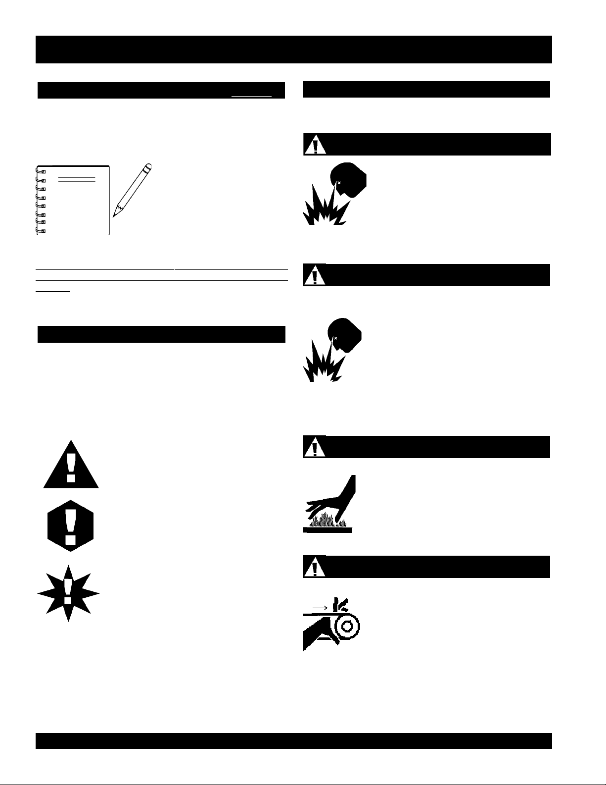
Lethal Exhaust Gases
Engine exhaust gases contain poisonous
carbon monoxide. This gas is colorless and
odorless, and can cause death if inhaled.
NEVER operate this equipment in a confined
area or enclosed structure that does not
provide ample free flow air.
Explosive Fuel
GASOLINE is extremely flammable, and its
vapors can cause an explosion if ignited. DO
NOT start the engine near spilled fuel or
combustible fluids. DO NOT fill the fuel tank
while the engine is running or hot. DO NOT
overfill tank, since spilled fuel could ignite if it
comes into contact with hot engine parts or
sparks from the ignition system. Store fuel in
approved containers, in well-ventilated areas
and away from sparks and flames. NEVER
use fuel as a cleaning agent.
DANGER: You WILL be KILLED or
SERIOUSLY injured if you do not follow
directions.
WARNING: You CAN be KILLED or
SERIOUSLY injured if you do not follow
directions.
CAUTION: You CAN be injured if you
do not follow directions.
Potential hazards associated with this vibration roller operation
will be referenced with Hazard Symbols which appear
throughout this manual, and will be referenced in conjunction
with Safety Message Alert Symbols.
Burn Hazards
Engine components can generate extreme heat.
To prevent burns, DO NOT touch these areas
while the engine is running or immediately after
operations. Never operate the engine with heat
shields or heat guards removed.
Rotating Parts
NEVER operate equipment with covers, or
guards removed. Keep fingers, hands, hair and
clothing away from all moving parts to prevent
injury.
PAGE 6 — MQ-MIKASA MRH-800DS VIBRATION ROLLER — PARTS & OPERATION MANUAL — REV. #3 (02/02/05)
Page 7
MRH-800DS — SAFETY MESSAGE ALERT SYMBOLS
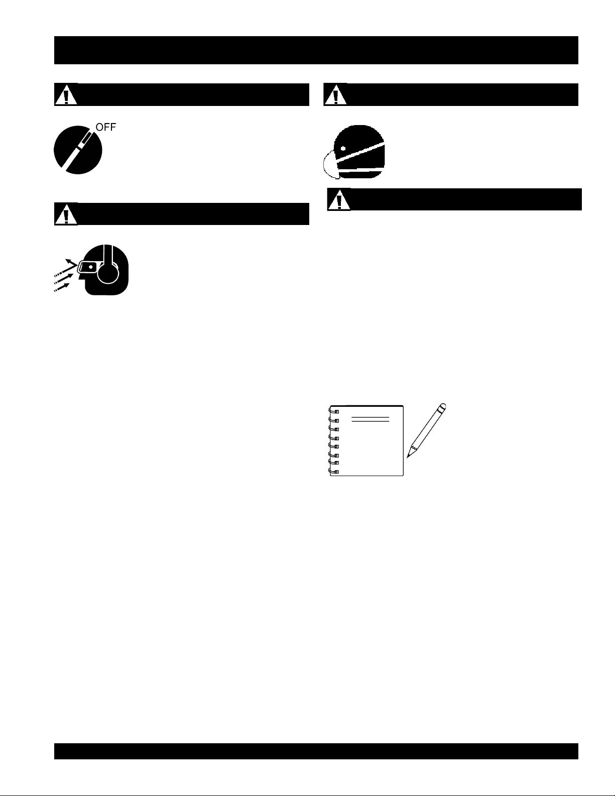
Accidental Starting
ALWAYS place the engine ON/OFF switch in
the OFF position, when the vibration roller is
not in use.
Sight and Hearing hazard
ALWAYS wear approved eye and hearing
protection.
Respiratory Hazard
ALWAYS wear approved respiratory
protection.
Equipment Damage Messages
Other important messages are provided throughout this manual
to help prevent damage to your vibration roller, other property,
or the surrounding environment.
NOTE
This vibration roller, other
property, or the surrounding
environment could be
damaged if you do not follow
instructions.
MQ-MIKASA MRH-800DS VIBRATION ROLLER — PARTS & OPERATION MANUAL — REV. #3 (02/02/05) — PAGE 7
Page 8
CAUTION:
Failure to follow instructions in this manual
may lead to serious injury or even death! This
equipment is to be operated by trained and
qualified personnel only! This equipment is
for industrial use only.
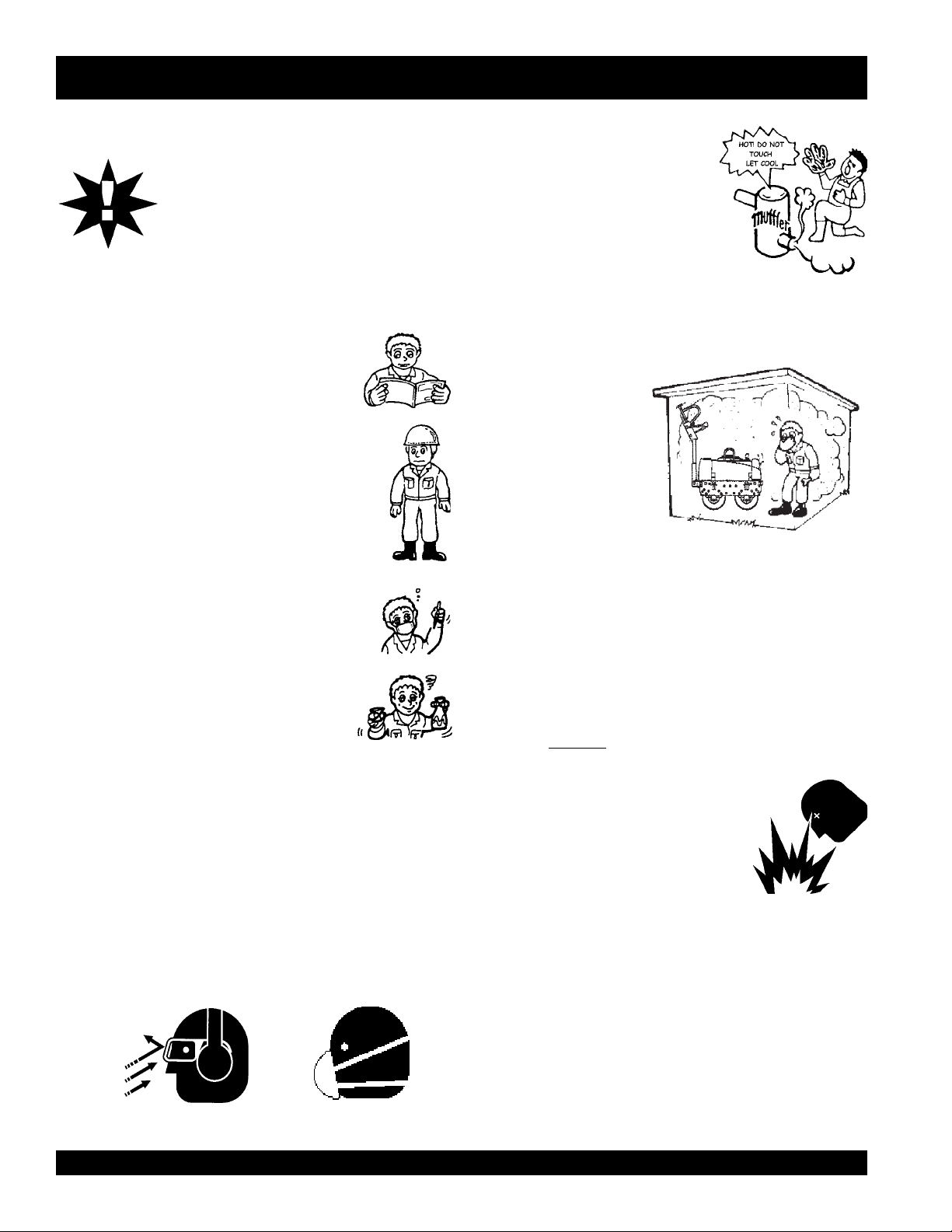
MRH-800DS — RULES FOR SAFE OPERATION
■
NEVER touch the hot exhaust manifold,
muffler or cylinder. Allow these parts to
cool before servicing engine or vibration
roller.
The following safety guidelines should always be used when
operating the MIKASA MRH-800DS Vibration Roller:
GENERAL SAFETY
■
DO NOT operate or service this equipment before
reading this entire manual.
■
This equipment should not be operated by
persons under 18 years of age.
■
NEVER operate this equipment without proper
protective clothing, shatterproof glasses, steeltoed boots and other protective devices required
by the job. ALWAYS wear slip resistant safety
shoes or boots.
■
NEVER operate this equipment when not feeling
well due to fatigue, illness or taking medicine.
■
NEVER operate this equipment under the
influence or drugs or alcohol.
■
NEVER use accessories or attachments, which are not
recommended by Multiquip for this equipment. Damage to
the equipment and/or injury to user may result.
■
Manufacturer does not assume responsibility for any accident
due to equipment modifications.
■
Whenever necessary, replace nameplate, operation and
safety decals when they become difficult read.
■
ALWAYS wear proper respiratory (mask), hearing and eye
protection equipment when operating the vibration roller.
■
High Temperatures – Allow the engine to cool before adding
fuel or performing service and maintenance functions. Contact
hot
with
■
The engine of this
vibration roller requires
an adequate free flow of
cooling air. NEVER
operate the vibration
roller in any enclosed or
narrow area where free
flow of the air is restricted.
If the air flow is restricted
it will cause serious
damage to the vibration
roller or engine and may cause injury to people and property.
Remember the vibration roller's engine gives off DEADLY
gases.
■
ALWAYS refuel in a well-ventilated area, away from sparks
and open flames.
■
ALWAYS use extreme caution when working with flammable
liquids. When refueling, stop the engine and allow it to cool.
DO NOT
explosion could result from fuel vapors, or if fuel is spilled on
a hot engine.
■
NEVER operate the vibration roller in
an explosive atmosphere or near
combustible materials. An explosion or
fire could result causing severe
harm or even death.
■
Topping-off to filler port is dangerous, as it tends to spill fuel.
■
ALWAYS store the vibration roller in a clean, dry location out
of the reach of children.
components can cause serious burns.
smoke around or near the machine. Fire or
bodily
■
NEVER run engine without air cleaner. Severe engine
damage may occur.
■
NEVER leave the vibration roller unattended, turn off engine.
■
CAUTION must always be observed while servicing this
vibration roller. Rotating parts can cause injury if contacted.
■
DO NOT leave vibration roller with engine running. Use
chock blocks if parking
PAGE 8 — MQ-MIKASA MRH-800DS VIBRATION ROLLER — PARTS & OPERATION MANUAL — REV. #3 (02/02/05)
vibration roller on a grade.
Page 9

MRH-800DS — RULES FOR SAFE OPERATION
■
ALWAYS use extreme care when operating near obstructions,
on slippery surfaces, grades and side slopes.
■
When reversing, particularly on the edges and banks of
ditches, as well as in front of obstacles, the operator must
stay in a standing position at a safe distance from the machine.
■
When operating near any house/building or pipelines, always
check the effect of machine vibration. Stop the work if
necessary.
■
Unauthorized equipment modifications will void all
warranties.
■
Refer to the
questions or information.
■
DO NOT operate the vibration roller with the front or rear
cover open.
■
Replace any worn or damaged vibration roller components
immediately.
■
ALWAYS turn the engine
maintenance.
■
ALWAYS make sure vibration roller is correctly secured to
the trailer. Check all supports attaching the vibration roller to
the trailer and make sure they are tight.
■
ALWAYS keep the machine away from workers and
obstacles. Also keep the immediate area free of bystanders.
■
ALWAYS check the machine for loosened threads or bolts
before starting.
■
ALWAYS read, understand, and follow procedures in
Operator’s Manual before attempting to operate equipment.
■
ALWAYS be sure the operator is familiar with proper safety
precautions and operations techniques before using vibration
roller.
■
A copy of this manual shall accompany the vibration roller at
all times.
■
DO NOT use worn out hoses or couplings; inspect daily.
Engine Owner's Manual
for engine technical
OFF
before performing
■
■
Emergencies
■
Maintenance Safety
■
■
■
■
■
■
■
Lifting
■
High Temperatures – Always stop engine and allow the
engine to cool before adding fuel, oil or performing service
hot
and maintenance functions. Contact with
can cause serious burns.
NEVER disconnect any
These devices are intended for operator safety. Disconnection
of these devices can cause severe injury, bodily harm or
even death! Disconnection of any of these devices will void
all warranties.
ALWAYS know the location of the nearest
and
first aid kit
Also know the phone numbers of the nearest
doctor
and
invaluable in case of an emergency.
NEVER lubricate components or attempt service on a
running machine.
ALWAYS allow the machine a proper amount of time to
cool before servicing.
Keep the machinery in proper running condition.
Fix damage to the machine immediately and always replace
broken parts.
Dispose of hazardous waste properly. Examples of
potentially hazardous waste are used motor oil, fuel and
fuel filters.
DO NOT use food or plastic containers to dispose of
hazardous waste.
DO NOT pour waste, oil or fuel directly onto the ground,
down a drain or into any water source.
The vibration roller has an operating weight of approximately
1562 lbs. (709 kg). Use lifting equipment capable of lifting
this weight.
. Know the location of the nearest telephone.
fire department
"emergency or safety devices"
. This information will be
components
.
fire extinguisher
ambulance
,
■
Make sure the engine is off before lifting the machine.
■
Use reliable cable in lifting the machine.
■
Lift upright with sufficient bearing capacity to prevent
machine from tilting or slipping.
■
When lifting, keep the machine away from workers and
animals.
MQ-MIKASA MRH-800DS VIBRATION ROLLER — PARTS & OPERATION MANUAL — REV. #3 (02/02/05) — PAGE 9
Page 10

MRH-800DS — OPERATION AND SAFETY DECALS
Figure 1 displays the operation and safety decals as they appear on the vibration roller. Should any of these decals become
damaged or unreadable, contact the Multiquip Parts Department for a replacement set.
Figure 1. Operation and Safety Decals
PAGE 10 — MQ-MIKASA MRH-800DS VIBRATION ROLLER — PARTS & OPERATION MANUAL — REV. #3 (02/02/05)
Page 11

MRH-800DS — OPERATION AND SAFETY DECALS
Figure 1. Operation and Safety Decals (Continued)
MQ-MIKASA MRH-800DS VIBRATION ROLLER — PARTS & OPERATION MANUAL — REV. #3 (02/02/05) — PAGE 11
Page 12

MRH-800DS — ROLLER SPECIFICATIONS
snoisnemiD )mm0601x296x0762(ni7.14x2.72x501
retemaiDmurD )mm604(.ni61
htdiWmurD)mm056(.ni6.52
SNOITACIFICEPSRELLORNOITARBIVSG008-HRM.1ELBAT
ecnaraelCbruC
gnahrevOediS)mm12(.ni38.
)retawhtiw(thgieWgnitarepO )gk017(.sbl2651
ycneuqerFnoitarbiVmpv003,
ecroFlagufirtneC fgk/nk004,2/5.32
metsySevirDrotoMciluardyH
metsySnoitarbiVemarF
dohteMnoitarbiVevirDtleB
tf
ahSrotarbiVniwT
ytililbaedarGseerged02
deepSgnikroW )hpk8.4-0(hpm3-0
yticapaCknaTleuF )sretil1.7(snollag88.1
liOgnitacirbuL )sretil52(snollag6.6
yticapaCknaTretaW )sretil04(snollag75.01
3
)mm342(.ni6.9
ledoMenignE 1KMVED-EE001Lledo
metsySgnitratS tratSlioceR/cirtcelE
PAGE 12 — MQ-MIKASA MRH-800DS VIBRATION ROLLER — PARTS & OPERATION MANUAL — REV. #3 (02/02/05)
MRAMNAY
Page 13

MRH-800DS — ENGINE SPECIFICATIONS
.2elbaTENIGNE)RAMNAY(SNOITACIFICEPS
ledoMenignE 1KMVED-EE001LRAMNAY
epyTenignEleseiDdelooc-riA
ekortSXeroBrednilyC )mm07x88(ni57.2x64.3
lpsiD)cc604(zolf7.31
tnemeca
tupuOmumixaMPH01
yticapaCknaTleuF)sretil5.5(strauq8.5
yticapaCliO )sretil56.1(strauq47.
thgieWteNyrD)gk35(.sbl6.611
)HxWxL(snoisnemiD )mm494x074x714(ni4.91x5.81x4.61
1
MQ-MIKASA MRH-800DS VIBRATION ROLLER — PARTS & OPERATION MANUAL — REV. #3 (02/02/05) — PAGE 13
Page 14
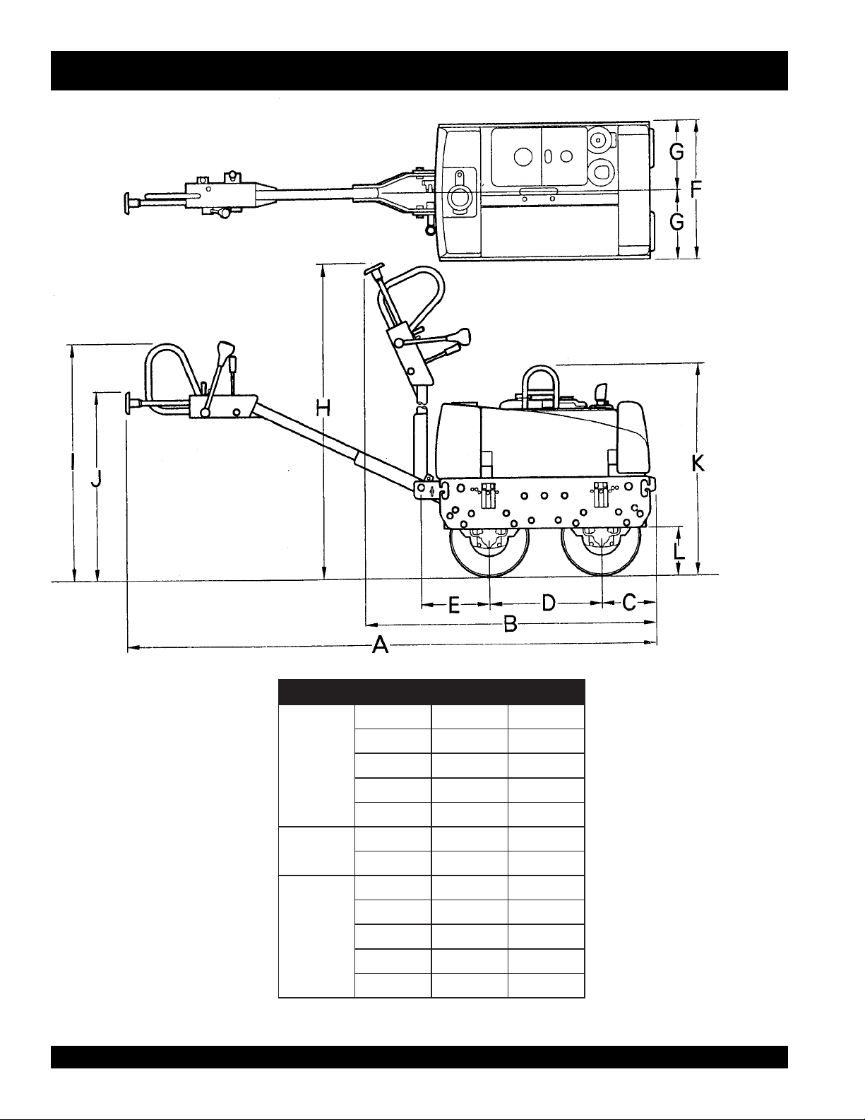
MRH-800DS— VIBRATION ROLLER DIMENSIONS
SNOISNEMID.3ELBAT
A.ni501.mm0762
B.ni75.mm5441
HTGNEL
HTDIW
THGIEH
C.ni01.mm552
D.ni8.22.mm085
E.ni8.31.mm053
F.ni2.72.mm296
G.ni6
H.ni3.87.mm0991
I.ni5.64.mm0811
J.ni4.73.mm059
K.ni7.14.mm0601
L.ni6.9.mm542
.31.mm643
Figure 2. MRH-800DS Vibration Roller Dimensions
PAGE 14 — MQ-MIKASA MRH-800DS VIBRATION ROLLER — PARTS & OPERATION MANUAL — REV. #3 (02/02/05)
Page 15

The Mikasa Model MRH-800DS is a powerful compacting
tool capable of applying a tremendous force in consecutive
impacts to a soil surface. Its applications include soil compacting
for backfilling for gas pipelines, water pipelines and cable
installation work.
The impact force of the MRH-800DS levels and uniformly
compacts voids between soil particles to increase dry density.
Features include:
Hydraulic transmission to allow speed change without
gear shifting.
Deadman device which when pressed or hit will
cause the travel lever to return to neutral position
bringing the machine to a stop.
A horn to warn of machine’s approach.
Non-corrosive water tank for the sprinkler system with a
capacity of more than 10 gallons.
Lifting hook to transport machine.
Front bumper and working light.
MRH-800DS— FEATURES
Narrow profile with less than one inch wall clearance.
Narrower width allows access to tighter areas. No
exposed hydraulic hoses.
Oil bath lubricated bearings and external vibration
for less servicing and more dependability.
Front and rear drum scrapers.
Drum sprinkler system controls located near the
operator.
Easy access to hydraulic components and hydraulic
filter.
MQ-MIKASA MRH-800DS VIBRATION ROLLER — PARTS & OPERATION MANUAL — REV. #3 (02/02/05) — PAGE 15
Page 16
MRH-800DS— VIBRATION ROLLER COMPONENTS
1
2
4
3
8
9
5
6
10
11
7
Figure 3. MRH-800DS Vibration Roller Components
PAGE 16 — MQ-MIKASA MRH-800DS VIBRATION ROLLER — PARTS & OPERATION MANUAL — REV. #3 (02/02/05)
Page 17

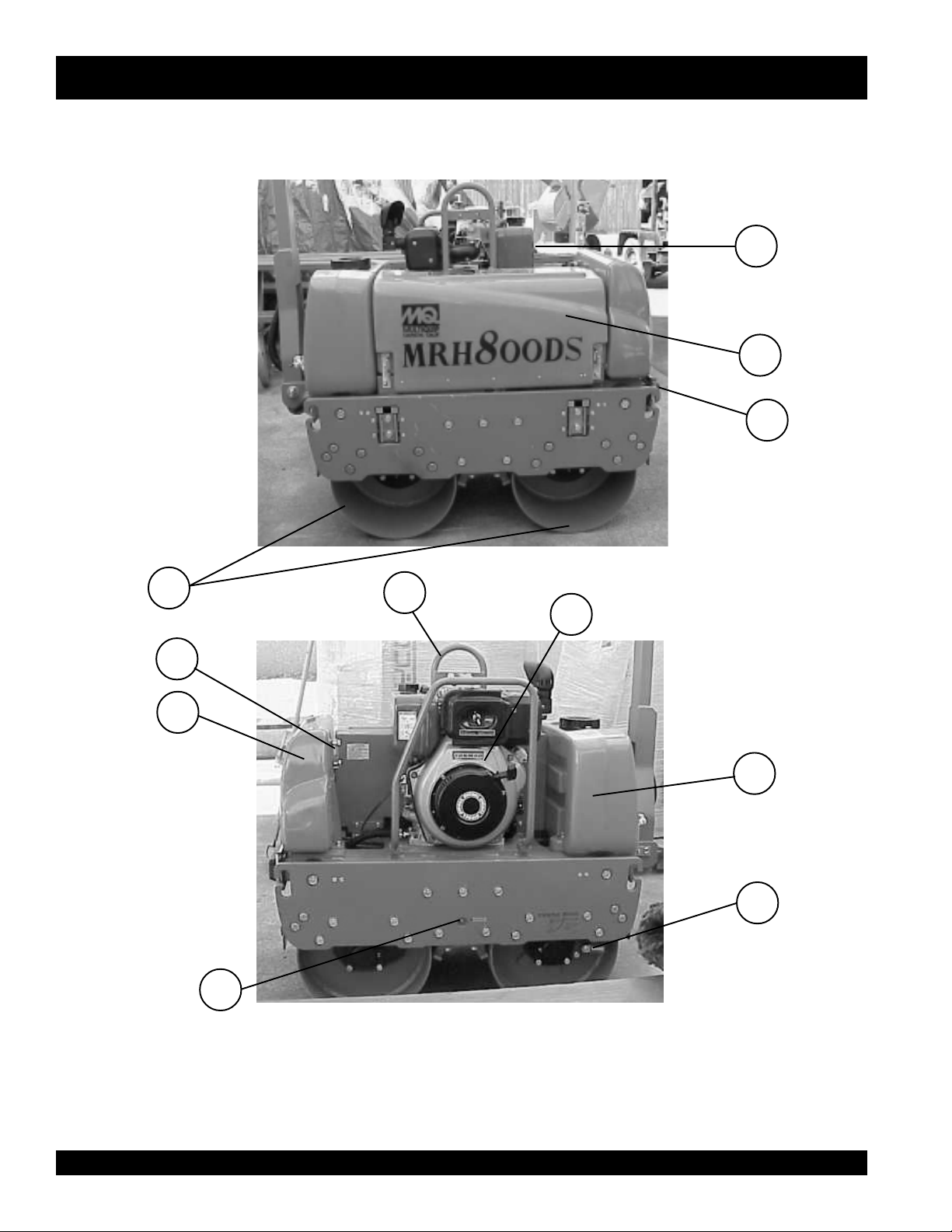
MRH-800DS— VIBRATION ROLLER COMPONENTS
Figure 3 illustrates the location of the major components
for the MRH-800DS Vibration Roller. The function of each
component is described below:
1. Fuel Tank/Cap – Fill with diesel fuel. Fuel tank holds
approximately 2 gallons (7.5 liters). DO NOT top off fuel.
Wipe up any spilled fuel immediately.
2. Center Cover – When opened and supported by strut,
provides access to oil pump and filter, battery, V-belt, and
clutch box.
3. Vibration Rollers – 25-inch wide steel drums that provide
compaction force in the compaction and patching of asphalt
type surfaces.
4. Front Headlights – Activate using switch on control
handle. Use to illuminate ground durring nighttime or low
light operating conditions.
5. Hydraulic Oil Gauge – Indicates the hydraulic oil level.
6. Oil Tank – Fill with proper grade of hydraulic oil.
7. Vibrator Oil Level Plug – Remove to check vibrator oil
level.
8. Lifting Hook – Used to lift the machine with crane or other
lifting device.
9. Engine – This machine uses the Yanmar L100A engine.
Refer to the engine Owner’s Manual for more information.
10. Water Tank– Holds 10.57 gallons (40 liters) for the sprinkler
system.
11. Parking Brake – Makes sure machine will not accidentally
move when parked or not in use.
MQ-MIKASA MRH-800DS VIBRATION ROLLER — PARTS & OPERATION MANUAL — REV. #3 (02/02/05) — PAGE 17
Page 18
3
4
MRH-800DS— HANDLE BAR/LEVER COMPONENTS
1
2
6
5
Figure 4. MRH-800DS Lever Components
PAGE 18 — MQ-MIKASA MRH-800DS VIBRATION ROLLER — PARTS & OPERATION MANUAL — REV. #3 (02/02/05)
Page 19

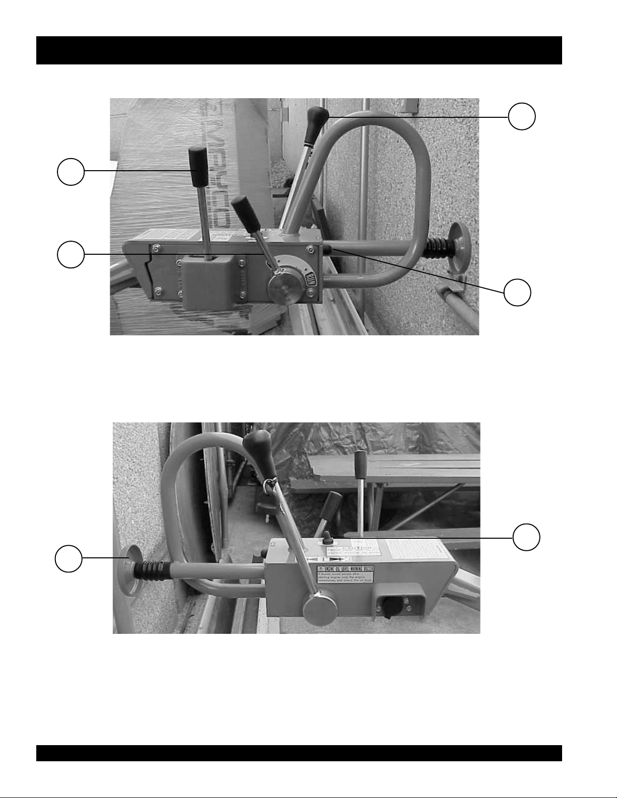
MRH-800DS — HANDLE BAR/LEVER COMPONENTS
HANDLE BAR/LEVER COMPONENTS
Figure 4 illustrates the location of the major lever
components on the handle bar of the machine. Each
component is described below:
1. Travel Lever – Controls the direction of travel of the
machine (forward and reverse).
2. Horn Button – When pressed, gives a warning sound of
the machine approaching.
3. Vibration Lever – Turns vibration on and off.
4. Throttle Lever – Controls the start up of the machine.
5. Dead-Man Device – When pressed or hit while traveling
in reverse, causes the travel lever to return to neutral
position to stop the machine.
6. Light ON/OFF Switch - Turns headlight on and off.
7. Starter Switch - Engine starts when key is turned to the
RUN position
MQ-MIKASA MRH-800DS VIBRATION ROLLER — PARTS & OPERATION MANUAL — REV. #3 (02/02/05) — PAGE 19
Page 20
MRH-800DS— ENGINE COMPONENTS
Figure 5. MVH-402DSB Engine Components
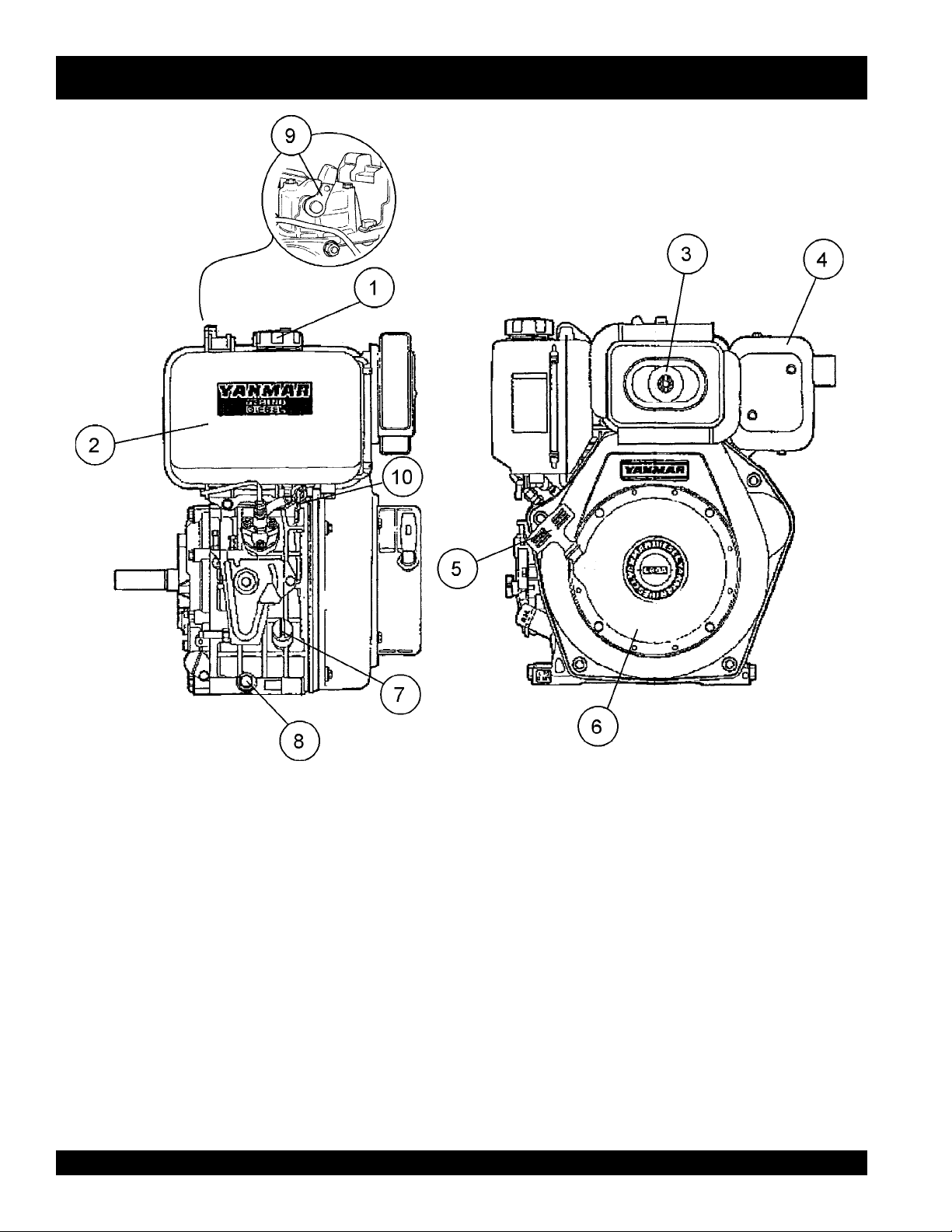
ENGINE COMPONENTS
Figure 5 illustrates the location of the major engine
components of the machine. Each component is described
below:
1. Fuel Filler Cap – Remove this cap to add unleaded
gasoline to the fuel tank. Make sure cap is tighten securely.
DO NOT over fill.
2. Fuel Tank – Diesel engine holds 5.8 quarts of diesel fuel.
3. Air Cleaner – Prevents dirt and other debris from entering
the fuel system. Remove wing-nut on top of air filter
cannister to gain access to filter element.
4. Muffler – Used to reduce noise and emissions.
5. Recoil Starter (pull rope) – Type of engine starting method.
Alternate type would be electric start (ignition key).
PAGE 20 — MQ-MIKASA MRH-800DS VIBRATION ROLLER — PARTS & OPERATION MANUAL — REV. #3 (02/02/05)
6. Recoil Starter – Housing for pull rope and starter.
7. Oil Filler Cap/Dipstick – Remove this cap to add oil to the
oil tank. Use dipstick to check oil level.
8. Oil Drain Plug – Unscrew plug to drain oil from engine
crankcase. Dispose of oil in a safe manner.
9. Decompression Lever – Press down before starting
engine. To prevent damage to the engine, DO NOT use for
any other purpose.
10. Fuel Cock – Controls the flow of diesel fuel to the engine.
Must be in the ON position when starting and running the
engine.
Page 21

NOTE PAGE
MQ-MIKASA MRH-800DS VIBRATION ROLLER — PARTS & OPERATION MANUAL — REV. #3 (02/02/05) — PAGE 21
Page 22

MRH-800DS— INSPECTION
DANGER
NEVER operate the
compactorin a confined
area or enclosed area
structure that does not
provide ample
.
of air
ALWAYS wear approved eye and hearing
protection before operating the compactor.
Before Starting
1. Read safety instructions at the
beginning of manual.
2. Remove dirt and dust, particularly
in theengine cooling air inlet,
carburetor and air cleaner.
3. Check the air filter for dirt and dust.
If air filter is dirty, replace air filter
with a new one as required.
4. Check carburetor for external dirt and dust. Clean with dry
compressed air.
free flow
3. Insert and remove the dipstick without screwing it into the
filler neck. Check the oil level shown on the dipstick.
4. If the oil level is low, fill to the edge of the oil filler hole with the
recommended oil type (Table 3). Maximum oil capacity is
1.16 quarts (1.1 liters).
Checking The Hydraulic System
1. Check the oil tank level gauge (Figure 7). Oil level
should be at the middle indication of the gauge or
higher. Fill as required
2. Check the surroundings of the oil tank, hydraulic
pump and motor for oil leakage.
Level should
be middle of
gauge or
higher
Figure 7. Hydraulic System Oil Level Gauge
5. Check fastening nuts and bolts for tightness.
6. Understand the geographical features and regulations of
the job site.
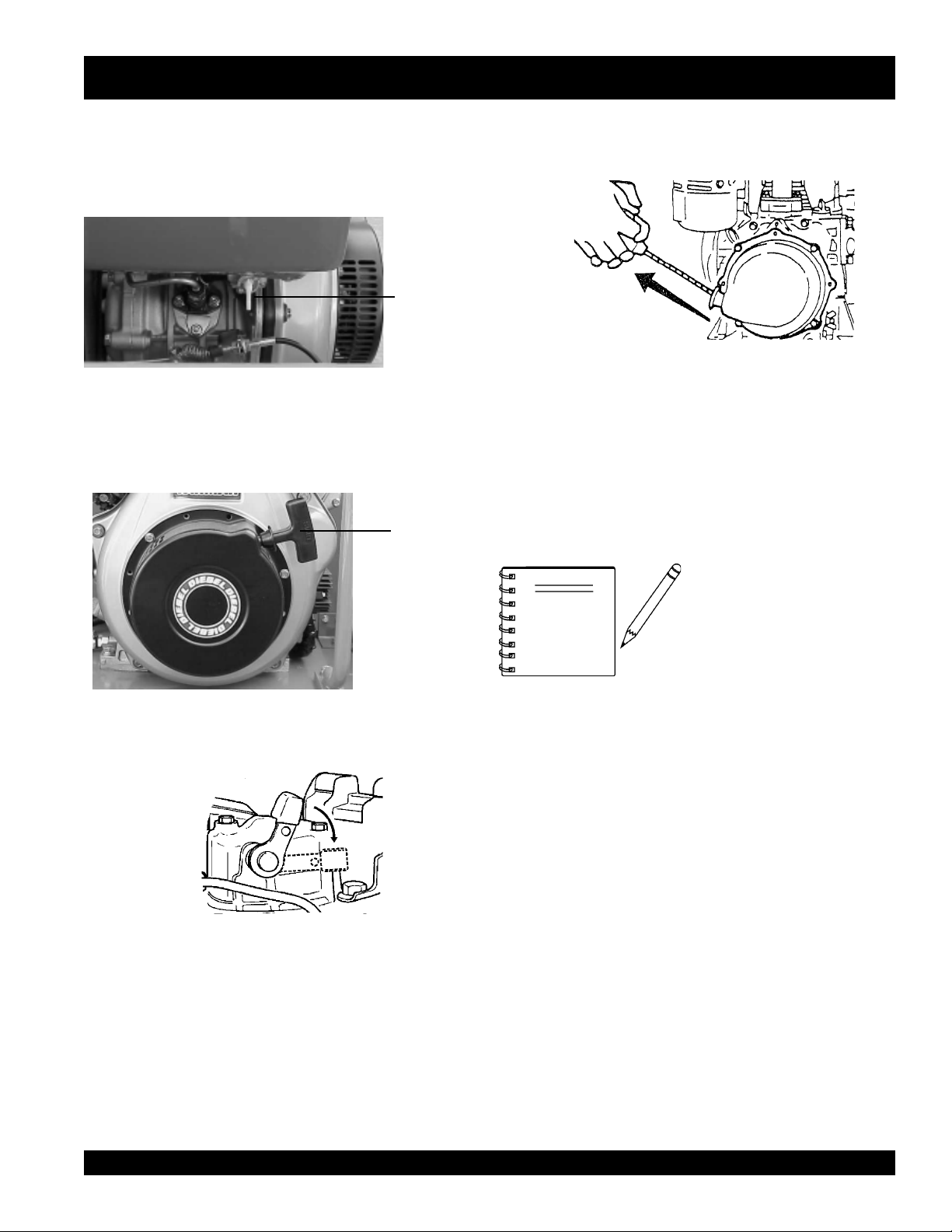
Engine Oil Check
1. To check the engine oil level, place the compactor on secure
level ground with the engine stopped.
2. Remove the filler dipstick from the engine oil filler hole
(Figure 6) and wipe clean.
Figure 6. Engine Oil Level
EPYTLIO.4ELBAT
nosaeS erutarepmeT epyTliO
DANGER
Checking The V-Belt
1. Remove the 2 bolts, one on each side of the center
cover, with a #13 socket wrench. Open the center
cover of the machine and support it with the strut by
inserting its end to the hole in the base (Figure 8).
2. Check V-belt for proper tension. Insufficient tension
causes weak vibration.
Center
Cover
Strut
V-Belt
ALWAYS keep hands and fingers away from
pinch points. DO NOT allow anyone to reach in
on dangerous sections of the machine to avoid
any accidents.
remmuS rehgiHroC°52 03-W01EAS
llaF/gnirpS C°01~C°52 02/03-W01EAS
retniW rewoLroC°0 01-W01EAS
PAGE 22 — MQ-MIKASA MRH-800DS VIBRATION ROLLER — PARTS & OPERATION MANUAL — REV. #3 (02/02/05)
Figure 8. Checking V-Belt Tension
Page 23

MRH-800DS— INSPECTION
Checking The Vibrator Oil Level
1. Check vibrator casing for any oil leakage.
2. If any leakage is noticed, remove the level plug on the side
of the plate (Figure 9).
3. Check the oil level.
Vibrator Oil
Level Plug
Figure 9. Checking Vibrator Oil Level
Fuel Check
1. Remove the fuel cap located on top of the engine fuel tank.
2. Visually inspect to see if the fuel level is low. If fuel is low,
replenish with unleaded gasoline using a strainer for
filtration. DO NOT top-off fuel. Wipe up any spilled fuel
immediately!
Checking Levers and Horn
1. Check travel, vibration, and throttle levers to make sure
they are functioning properly (Figure 4).
2. With travel lever placed in reverse, push the deadman
device and verify that the travel lever returns to neutral
position. The travel lever stays in neutral position once the
deadman device is released.
3. Press the horn and verify that it functions properly.
Checking Scrapers
1. Check scrapers and make sure that they are not clogged
with mud, bent or damaged (Figure 11).
2. Adjust clearance between drums and scrapers as
necessary.
DANGERDANGER
DANGER
DANGERDANGER
Motor fuels are highly
flammable and can be
dangerous if mishandled.
DO NOT smoke while
refueling. DO NOT attempt to refuel the pump
if the engine is
Checking Water Tank
1. Check the water tank to see if filled. Add water if necessary.
The water tank has a capacity of approximately 10 gallons
(40 liters) (Figure 10).
hot! or running
Figure 10. Checking Water Tank
.
CAUTION :
Scrapers
Figure 11. Checking Scrapers
Checking Bolts, Nuts and Screws
1. Check bolts, nuts, and screws on various parts of the
machine, including the engine, for proper tightness.
Positioning the Handle Bar
1. Release the handle bar release pin (Figure 12) and position
the handle bar to the lowered position before starting
operation.
2. When machine is not in use, release the handle bar release
pin and position the handle bar to the upright position.
Handle Bar
Release Pin
Be careful not to confuse the water tank with the
oil tank.
MQ-MIKASA MRH-800DS VIBRATION ROLLER — PARTS & OPERATION MANUAL — REV. #3 (02/02/05) — PAGE 23
Figure 12. Positioning the Handle Bar
Page 24

MRH-800DS— INITIAL STARTUP
CAUTION :
DO NOT attempt to operate the roller until the Safety, General
Information and Inspection sections of this manual have been
read and thoroughly understood
This section is intended to assist the operator with the
start-up
be read carefully before attempting to use the compactor in the
field.
STARTING THE ENGINE
The engine can be started by motor (electric) or manually
(recoil). Refer to Figures 3 and 4 for the location of
controls and components.
of the roller. It is extremely important that this section
.
initial
CAUTION :
Make sure to follow all safety rules referenced in
the safety section of this manual before operating
roller. Keep work area clear of debris and other
objects that could cause damage to the roller or
bodily injury.
5. Insert the starter key into the key switch and turn it to
the RUN position (Figure 14). The buzzer should
sound at this time.
6 Turn the starter key further to the right to the START
position to start the engine. Buzzer stops sounding
when the engine speed increases. With safety switch
equipped, motor runs only when the travel lever is in
the neutral position.
Figure 14. Starter Key (Run Position)
CAUTION :
When the engine is running, NEVER turn the
starter key to the START position
Electric Start
1. On the control handle:
A. Move the
B. Move the
C. Move the
4. Open the fuel cock by turning it clockwise to the down
position (Figure 13).
throttle lever
travel lever
vibration lever
to the RUN position.
to the NEUTRAL position.
to the OFF position.
Fuel Cock
(Open
Position)
7. If the engine fails to start, DO NOT continue to rotate
the starter key for more than 5 seconds. Return the
key to the RUN position and wait 20 to 30 seconds
before starting again.
8. After starting the engine, continue to warm up the
engine for about 3 to 10 seconds especially in cold
weather.
9. If the buzzer does not stop sounding after the engine
has started, shutdown engine immediately and check
engine oil level. The buzzer functions as engine oil
level warning also.
Figure 15. Starter Key (Start Position)
Figure 13. Open Fuel Cock
PAGE 24 — MQ-MIKASA MRH-800DS VIBRATION ROLLER — PARTS & OPERATION MANUAL — REV. #3 (02/02/05)
Page 25
MRH-800DS— INITIAL STARTUP
Recoil Start
1. Move the throttle lever to the RUN position.
2. Open the fuel cock by turning it clockwise to the down
position (Figure 16).
Fuel Cock
(Open
Position)
5. Pull the starting handle hard and fast to start engine
(Figure 19).
Figure 19. Engine Start Handle
Figure 16. Open Fuel Cock
3. Pull the starting handle slowly until you feel some
resistance (Figure 17). Return handle to original
position.
Pull
Handle To
Start
Figure 17. Engine Start Handle
4. Push down the decompression lever (Figure 18).
6. If the engine does not start, repeat steps
3 through 5.
NOTE
When starting with a motor
starter, a decompressor is
not normally required.
However, when ambient
temperature or battery
charger level is low, use of
a decompressor will help
make the start-up easier.
Figure 18. Decompression Lever
MQ-MIKASA MRH-800DS VIBRATION ROLLER — PARTS & OPERATION MANUAL — REV. #3 (02/02/05) — PAGE 25
Page 26
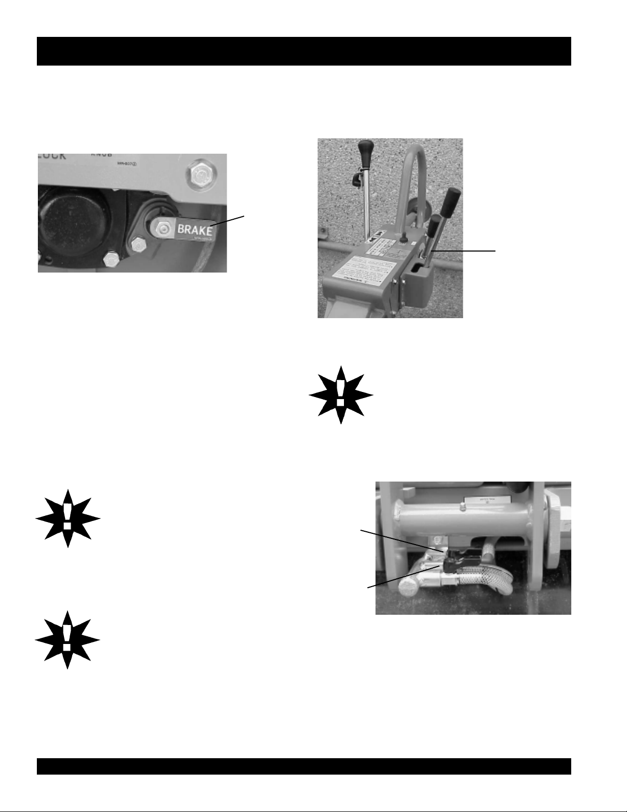
MRH-800DS—OPERATION
TRAVELING
1. Before starting to travel, make sure to release parking brake
located on the left side of the rear roller. If the parking brake
lever is tight, moving the roller back and forth will make it
easier (Figure 20).
Parking
Brake
(Released
Position)
Figure 20. Parking Brake
2. With the throttle lever in the RUN position, increase
the engine rotation.
3. Push the travel lever forward slightly. This will cause
the roller to travel forward at slow speed.
4. To increase the travel speed, push the travel lever
further.
5. Travel speed can be varied between 0 and 3 km/h
(both forward and reverse).
6. Push the travel lever backward to go in the reverse
direction.
CAUTION :
DO NOT reduce speed during work. When
shifting travel lever from forward to reverse,
be sure to stop the lever at the neutral
position first before moving the lever to the
opposite direction. DO NOT shift the lever
from forward to reverse (or reverse to
forward) in one motion.
CAUTION :
After test travel, shut down engine and
check for any problems including oil
leakage. If any trouble is found, correct the
problem before attempting to operate the
roller again.
VIBRATING
1. Shift the vibration lever AWAY from its OFF position. The
vibration lever will automatically spring forward and the
roller will start vibrating (Figure 21).
CAUTION :
WATERING
1. For watering work, turn the water cocks clockwise, at the
rear of the machine, to start sprinkling. (Figure 22).
Watercock
for Front
Drum
Watercock
for Rear
Drum
Off Position of
Vibration Lever
Figure 21. Vibration Lever
Using vibration with clutch slipping causes
the clutch to burn. Also, vibration should
NOT be used over completely compacted
area, paved road surface, or with stationary
roller.
Figure 22. Water Cocks
PAGE 26 — MQ-MIKASA MRH-800DS VIBRATION ROLLER — PARTS & OPERATION MANUAL — REV. #3 (02/02/05)
Page 27

SAFETY FEATURES
MRH-800DS—OPERATION
1. A horn is provided to warn of approach.
2. The dead man device prevents accidental traveling
in reverse. It automatically makes the travel lever
return to neutral position by stopping the machine
when an object comes in contact with the dead man
device.
STOPPING
1. With travel lever in the NEUTRAL position, and the
vibration lever in the OFF position, return the throttle
lever to the START position. Allow the machine to
cool down for 3 to 5 minutes.
2. Push the throttle lever forward to stop the engine. In
a motor start, return the key switch to the STOP
position as soon as the engine stops.
Bypass
Valve
Bolt
CAUTION :
CAUTION :
Neglecting to return the key switch to the
STOP position will cause the battery to
discharge making start up impossible the
next time.
3. After the engine stops, close the fuel cock.
4. Lock the parking brake by pulling the brake lever
and rotating it 90 degrees clockwise.
Parking brake system should
NOTE
always be kept clean to avoid
mud deposits.
LIFTING
1. Use a crane or lift to load and unload the machine. A
skilled crane operator is required to perform the job.
2. When lifting the machine, check for any damaged or
loose bolts, lifting hooks, and shock mounts.
3. Check any damaged or loose bolts in the guard frame to
avoid machine sliding off.
4. Make sure that the machine is shut off before machine is
lifted.
5. Use reliable cable for lifting.
6. ALWAYS lift the machine vertically and keep the
machine away from workers and animals.
Figure 23. Location of Bypass Valve Bolt
NEVER tow roller with any type of vehicle.
Doing so will damage the hydraulic system.
NEVER perform unloading procedure on a
slope. This may cause roller to roll down if
parking brake or blocking is deficient.
7. DO NOT lift the machine higher than the required
UNLOADING
1. If you need to move the roller by pushing it manually
once engine is stopped, loosen bolt of bypass valve
on oil pump by one rotation counterclockwise. This
will cause the hydraulic break to disengage and allow
the roller to be moved more easily (Figure 23).
2. After moving, tighten the bolt again. Tightening torque
is 55 to 70 kgf-cm.
MQ-MIKASA MRH-800DS VIBRATION ROLLER — PARTS & OPERATION MANUAL — REV. #3 (02/02/05) — PAGE 27
height.
TRANSPORTING
1. Always make sure that the machine is shut off while
being transported.
2. Check that the fuel cap is properly closed and
tightened.
3. When traveling long distances or on rugged terrain,
drain the fuel of the machine before transporting.
4. Tie down the machine securely on the
transportation so that it will not move or topple over.
Page 28

MRH-800DS—MAINTENANCE
CAUTION:
Inspection and other services should ALWAYS
be carried out on hard and level ground with the
engine shutdown.
Inspection and Maintenance Service Tables.
1. To make sure your plate compactor is always in good
working condition before using, carry out the maintenance
inspection in accordance with Tables 5 through 7.
SD008-HRM.5ELBATNOITCEPSNIENIHCAM
METI
gnissiMroesooL
swercS
straPdegamaD
gnillortnoCfonoitcnuF
traPmetsyS
FOSRUOH
NOITAREPO
sruoh8yrevE
)yadyreve(
sruoh8yrevE
)yadyreve(
sruoh8yrevE
)yadyreve(
SKRAMER
CAUTION:
Fuel piping and connections should be replaced
every 2 years.
METINOITAREPOFOSRUOH
kaeLleuFroliO)yadyreve(sruoh8yrevE
sdaerhT
tnemhsinelpeR
gnE
gninaelCretliFriAsruoh001yrevE
nigneetarapeseeS
SD008-HRM.6ELBATKCEHCENIGNE
gninetsaFfossenthgiT
nakcehCliOenignE
d
)level
tnemecalpeRliOeni
sruoh001
)yadyreve(sruoh8yrevE
)yadyreve(sruoh8yrevE
mumixamdeificepsothsinelpeR(
ot05yrevenehtsruoh52tsrifretfA
.kcehcenignenosliatedroflauname
kaeLmetsySciluardyHsruoh001yrevE72egapeeS
tarbiVsruoh001yrevE72egapeeS
kcehCliOro
liOrotarbiV
tnemecalpeR
kcehCliOciluardyHsruoh001yrevE62eg
liOciluardyH
tnemecalpeR
kcehC)hctulc(tleb-Vsruoh002
kcehCyrettaBsruoh001yrevE82egapeeS
yrevE72egapeeS
CAUTION:
These inspection intervals are for operation
under normal conditions. Adjust your inspection
intervals based on the number of hours the roller
is in use, and your particular working conditions.
sruoh003yrevE62egapeeS
002retfatsriF
yreveneht,sruoh
sruoh000,1
Daily Service
z
Check for leakage of fuel or oil.
z
Check for loose screws including tightness. See Table 7
below (tightening torque ), for retightening:
apeeS
mm6 mm8 mm01 mm21 mm41 mm61 mm81 mm02
lairetaM
72egapeeS
T4 07 051 003 005 057 001,1 004,1 000,2
T8-6 001 052 005 008 003,1 000,2 007,2 008,3
T11 051 004 008 002,1 000,2 009,2 002,4 006,5
~003
* 001
z
Remove soil and clean the bottom of compaction plate.
z
Check hydraulic pump, piping and hose for any leakage.
~056
053
007
)munimulafositrap-retnuocesacnI(*
kramsilairetamfoytilauqdnalairetaM
)mc/gk.ni(EUQROTGNINETHGIT.7ELBATRETEMAID
)dednahthgirllaeraenihcamsihthtiwesunisdaerhT(
.wercsdna,tlobhcaenode
A loosened hydraulic hose can be a cause for leakage.
Check hydraulic hose connections with wrench applied for
tightness.
z
Check engine oil.
PAGE 28 — MQ-MIKASA MRH-800DS VIBRATION ROLLER — PARTS & OPERATION MANUAL — REV. #3 (02/02/05)
Page 29

CLUTCH
PULLEY
VIBRATOR
PULLEY
MRH-800DS—MAINTENANCE
Engine Oil Replacement:
1. Replace engine oil in the first 25 hours of operation and
every 50 to 100 hours afterwards.
2. Oil may be drained more easily when it is warm after
operation (For more details, see separate engine Owner's
Manual).
Air Filter
1. The air filter element should be cleaned because a clogged
air cleaner can cause poor engine starting, lack of power
and shorten engine life substantially.
CAUTION:
CAUTION :
Figure 24. Engine Air Filter and Element
2. To clean or replace air filter loosen the wing nut on the air
filter housing (Figure 24) remove the cover and take out air
filter cartridge. If only cleaning of the air filter is desired blow
through the air filter cartridge from the inside, moving a jet of
dry compressed air up and down until all dust is removed.
VIBRATION CLUTCH ADJUSTMENT
1. Move vibration lever to the OFF position.
2. Loosen the front and rear nuts at the end of vibration clutch
cable (Figure 25).
3. Turn in the nut on the front side again and at the position
that release fork starts to move, turn in the nut by one or two
threads. Lock it a this position together with the rear nut.
HYDRAULIC SYSTEM INSPECTION AND SERVICE
1. Check motor and pump for any damage.
2. Check hoses and pipes for proper tightness and make sure
there are no leaks.
3. Check nylon tubes for hydraulic oil intake and drain.
Retighten brass nut if loose and if a leak is detected. If leak
continues after retightening, replace nylon tube, nut and
sleeve.
NEVER attempt to check the V-belt with the engine running. Severe injury can occur if your hand
gets caught between the V-belt and the clutch
(Figure 26). Always use safety gloves.
Figure 26. V-Belt Hazard
Excessive turning of front nut may cause the
sliding engagement of clutch to take place or
no vibration takes place even when vibration
lever is engaged.
On the other hand, insufficient turn may cause
sliding engagement of clutch even when the
vibration lever is placed in the OFF position or
for vibration to remain engaged.
4. Check oil tank for proper oil level using the hydraulic system
oil level gauge (See Figure 7). Make sure hydraulic oil has
not whitened or emulsified. Whitish color means aeration in
Rear Nut
Fork
Front Nut
Figure 25. Vibration Clutch Adjustment
MQ-MIKASA MRH-800DS VIBRATION ROLLER — PARTS & OPERATION MANUAL — REV. #3 (02/02/05) — PAGE 29
pump. Retighten pipe and correct level of oil. Emulsification
means water in the hydraulic oil. Replace the oil.
ROLLER INSPECTION AND ADJUSTMENT
1. Refer to Table 8 for oil and grease requirements.
2. Check oil tank level daily.
3. Check the machine for oil leak and proper function of lever,
cables, and links daily.
Page 30

zz
z
DO NOT close the exhaust outlet of battery. The gas pressure
MACHINE MAINTENANCE
1. At the end of each day’s operation, wash down dust and
dirt off the machine. Clean area around drums ad scrapers
making sure all mud is removed.
2. Drain water tank completely.
3. Cover the machine to prevent dust and store in dry place
away from sun exposure.
LONG TERM STORAGE
1. Conduct thorough lubrication and oil change.
2. Disconnect battery terminals and dismount battery from
machine. Store battery.
3. If there a possibility that ambient temperature will drop
below freezing point, add antifreeze agent to coolant.
4. Cover the inlet and outlet of air cleaner and muffler
securely.
5. Store machine indoors. Do not leave outdoors.
Refer to Table 7 for lubrication necessary for the machine.
BATTERY MAINTENANCE
DANGER :
Lead-acid battery contains sulfuric
acid, which may damage eyes or
skin on contact.
zz
building up in the battery may cause explosion.
zz
z
Before using a battery charger, read and understand the
zz
charger instruction manual thoroughly.
zz
Charge the battery in a non-spark, well-ventilated area. Avoid
z
zz
fire from cigarette sparks or matches.
1. If a battery has not been used for some time, reduce
the charge level initially to protect each plate inside
the battery.
2. Check the battery terminals periodically to ensure
that they are in good condition.
3. Use wire brush or sand paper to clean the battery
terminals.
4. Check battery for cracks or any other damage. If white
pattern appears inside the battery or paste has
accumulated at the bottom, replace the battery.
5. Measure the specific gravity of electrolyte:
zz
z
zz
zz
z
zz
6. If the machine will not be in operation for a long
period of time, charge the battery sufficiently, tighten
all caps, correctly, store in cool dry place and check
the battery charge level every month to maintain the
performance of the battery.
BATTERY CABLE CONNECTION
MRH-800DS—MAINTENANCE
completely charged: 1.270 - 1.290
needs charging: 1.260 or lower
1. When removing cable, disconnect the ground side (normally
negative) first (Figure 27).
FOR YOUR SAFETY:
zz
z
ALWAYS wear a face shield to avoid acid getting into the
zz
eyes. If acid gets in contact with eyes, flush immediately with
clean water and get medical advice.
zz
z
Wear rubber gloves and protective clothes to keep acid off
zz
skin. If acid gets in contact with skin, wash off immediately
with clean water.
zz
z
Use a flashlight to check battery electrolyte level. ALWAYS
zz
check the engine is stopped.
zz
z
DO NOT charge battery or jump-start engine when the
zz
battery is frozen. Warm the battery to 15 degrees F or battery
may explode.
zz
z
Replace the battery with the same or similar capacity battery
zz
or battery may explode.
PAGE 30 — MQ-MIKASA MRH-800DS VIBRATION ROLLER — PARTS & OPERATION MANUAL — REV. #3 (02/02/05)
Negative
Terminal
Positive
Terminal
Figure 27. Battery Connection
2. When installing cable connect the ground side (normally
negative) last.
Page 31

FORWARD AND REVERSE TRAVEL ADJUSTMENT
1. If neutral position for forward and reverse travel has been
displaced, conduct the neutral adjustment.
2. If roller travels forward with the ball of ball plunger remaining
in V slot of the guide, loosen M8 bolt and slide the slide
plate slightly toward the engine. If the roller travels
backward, slide the plate towards side plate (Figure 28).
MRH-800DS—MAINTENANCE
Plunger
M8 Bolt
Figure 28. Adjustment of Neutral Position
3. With M8 bolt tightened, start engine and check the neutral
for forward and reverse. If still displaced, repeat the
procedure.
4. If neutral position of forward/reverse lever has been
displaced, use the turn buckle located on the oil pump side
of forward/reverse cable.
Guide
Slide Plate
MQ-MIKASA MRH-800DS VIBRATION ROLLER — PARTS & OPERATION MANUAL — REV. #3 (02/02/05) — PAGE 31
Page 32

MRH-800DS—MAINTENANCE
TRAHCNOITACIRBULSD008-HRM.8ELBAT
METI
arbiV
,reveL
liOrotarbiVliOecalpeR
liOenignEliOecalpeR
noit
liOciluardyHliOecalpeR
,reveLlevarT
reveLelttorhT
ECNANETNIAM
DEDEEN
noitarepO
noitarepOfo
noitacirbuLddA
gnidilSotliO
straP
noitarepO
YCNEUQERFEPYTNOITACOL
fosruoH003yrevE
02ot01retfA-yllaitinI
noitarepOfosruoH
ot05yrevE-retfaerehT
noitarepOfosruoH001
fosruoH05yrevE
AS92erugiFees
)remmuS-gnirpS(
)retniW-llaF(
03W01EAS
xE(
:ytisocsiV
noigerdloc
sruoH0051ot0001yrevE
noigermrawrof-
64sulleTllehS
)sretil52(
liOnoitacirbuL4erugiFees
)sretil5.1(03W01E
03W01EASro03#EAS
03W01EASro02#EAS
)noigeRdloCylemert
rof-tnelaviuqe23GVOSI
tnela
viuqe65ro64GVOSI
htiwyrotcafmorfdeppihS
6erugiFees
7erugiFees
s'naMdaeD
eciveD
raBeldnaH
niPesaeleR
gniraeB
revoC
xoBhctulC
eveLlevarT
r
retliFliOretliFliOecalpeR
esaerGetacirbuL
gnittiF
tacirbuL
gnittiF
gnittiF
gnittiF
straP
esaerGe
E
esaerGetacirbuL
esaerGetacirbuL
gnidilSetacirbuL
noitarepO
noitarepO
noitarepO
noitarepO
noitarepO
noitarepO
fosruoH05yrevE
fosruoH05yrevE
fosruoH05yrev
fosruoH05yrevE
fosruoH05yrevE
2retfA-yllaitinI
noitarepOfosruoH
fosruoH5
005yrevE-retfaerehT
esaerG4erugiFees
esaerG23erugiFees
esaerG13,03serugiFees
esaerG52erugiFees
esaerG4erugiFees
norcim01eniuneGasakiM
repaPretliF
62erugiFees
PAGE 32 — MQ-MIKASA MRH-800DS VIBRATION ROLLER — PARTS & OPERATION MANUAL — REV. #3 (02/02/05)
Page 33

Vibrator Oil
Level Plug
Figure 29. Vibrator Oil Maintenance
MRH-800DS—MAINTENANCE
Handle Bar Release
Pin Grease Fitting
Figure 32. Handle Bar Maintenance
Vibrator Oil
Drain Plug
Clutch Box Grease Fitting
FIgure 30. Bearing Cover Grease Fitting
Bearing Cover Grease Fitting
Figure 31. Bearing Cover Maintenance
MQ-MIKASA MRH-800DS VIBRATION ROLLER — PARTS & OPERATION MANUAL — REV. #3 (02/02/05) — PAGE 33
Figure 33. Clutch Box Maintenance
Hydraulic Oil Filter
Figure 34. Hydraulic Oil Filter Location
Page 34

NOTE PAGE
PAGE 34 — MQ-MIKASA MRH-800DS VIBRATION ROLLER — PARTS & OPERATION MANUAL — REV. #3 (02/02/05)
Page 35

MRH-800DS— ROLLER TROUBLESHOOTING
GNITOOHSELBUORT.9ELBAT
MOTPMYSMELBORPELBISSOPNOITULOS
.levarttonseodtinU?degagnellitsekarbgnikraP .reveleka
?hctulclagufirtnecevitcefeD .hctulcecalperroriape
?egnalfdnagnilpuocrebburdegamaD .egnalfdnagnilpuocrebburecalpeR
?knildnaelbaclevartevitcefeD .knildnael
rolevarttonseodtinU
odegamaD.retlifecalpeR
.htoomstonsilevart
elrodegamaD .rotomciluardyhecalperroriapeR
?noitatormurddaB .murdec
?retlifliodeggolcr
?epipciluardyhgnikaelrodegamaD .strapecalperroriapeR
?liodetanimatnocrolevelliowoL
?pmupciluardyhgnikaelrodegamaD .pmupciluardyhecalperroriapeR
?rotomciluardyhgnika
?gniraebdnaraegmurddegamaD.strapriapeR
?hctulclagufirtnecevitcefeD .hctulcecalperroriapeR
R
?reparcsnidumhcumootroreparcsdegamaD .reparcsriaperroecalpeR
rbgnikrapesaeleR
alperroriapeR
baclevartecalperroriapeR
.lioecalperrohsinelpeR
leb-VgnippilsrodegamaD .noisnettsujdarotleb-VecalpeR
?t
?egaknildnaelbacnoitarbivdegamaD
roetarbivtonseodtinU
.noitarbivkaewsah
eD.tleb-VecalpeR
?hctulcnoitarbivdegamaD .hctulcecalperrotsujdA
?tleb-Vyelluprotarbivhctulcevitcef
?dnahhtiwylhtoomsnruttonseodrotarbiV
.egaknil
onsilevel
iaperroecalpeR
.hgihylevissecxet
dnaelbacnoitarbivr
liofikcehC.rotarbivriaperdnakcehC
MQ-MIKASA MRH-800DS VIBRATION ROLLER — PARTS & OPERATION MANUAL — REV. #3 (02/02/05) — PAGE 35
Page 36

MRH-800DS— ENGINE TROUBLESHOOTING
GNITOOHSELBUORTENIGNE.01ELBAT
NOTPMYSMELBORPELBISSOPNOITULOS
?noitisop"POTS"nisirevellortnocdeepS .noitisop"TRATS"otrevellortnocdeepsteS
oitcejnignihcaerleufoN .metsysleuferitnekcehC.leufddA
?pmupleufevitcefeD.pmupleufecalpeR
uF .knatnaelcdnaretlifleufecalpeR
sitratsrotratstonlliwenignE
,deyaled
.revodenruteb
oltA
.tratston
nacenignehguohtla
lliwenigneserutarepmetw
?deggolcretlifle
?enilylppusleufytluaF.enilleufriaperroecalpeR
?wolootnoisserpmoC
?wolooterusserpliO.erusserplioenignekcehC
erutarepmetgnitratswoL
?serutarepmetwolot
?pmupn
A.sevlavdnarednilyc,notsipkcehC
.launamriaperenignerepriaper
?yltcerrocgnikrowtonrotcejnileuF
dedeecxetimil
ecnatsiseretauqedanisahsetarapesleuF
.launamriaperenigne
.ytisocsivlioreporp
.leufleseidedargretniw
occanirotcejniecalperroriapeR
rotsujd
htiwecnadr
dnasnoitcurtsnignitratsdlochtiwylpmoC
leuf)dibrutton(raelcrehtehwkcehC
mo
rfhcated(enilleufehtmorfsegreme
rodibrutsileufehtfI.)pmupnoitcejni
ehtniardroenigneehtpumraw,detarapes
tiwleufeR.metsysylppusleufetelpmoc
h
?kcihtootlioenignE
elttorhT .noitisopNURotrevelelttorhtnoitisopeR
sanoosspotstubserifenignE
.ffodehctiwssiretrats
gnirudflestiybspotsenignE
.noitarepolamron
F.retlifleufecalpeR
?dekcolbretlifleuF.retlifleufecalpeR
?dekcolbylppusleuF .me
?ytpmeknatleuF.leufddA
?dekcolbretlifleu
?noitisopPOTSnirevel
nignellifeR
.tnemnorivneretniwroflio
tsysleuferitneehtkcehC
foepyttcerrochtiwesacknarce
PAGE 36 — MQ-MIKASA MRH-800DS VIBRATION ROLLER — PARTS & OPERATION MANUAL — REV. #3 (02/02/05)
Page 37

MRH-800DS— ENGINE TROUBLESHOOTING
)DEUNITNOC(GNITOOHSELBUORTENIGNE.01ELBAT
NOTPMYSMELBORPELBISSOPNOITULOS
?ytpmeknatleuF.retlifleufecalpeR
?deggolcretlifleuF.retlifleufecalpeR
dnatuptuo,rewopenignewoL
.deeps
?noitisop
?llufootlevellioenignE ?levellioenignetcerroC
?
dnatuptuorewopenignewoL
tsuahxekcalb,deepswol
.ekoms
dekcolbretlifriA .retlifriaecalperronaelC
?
rotcejnitanoitcnuflaM.launamenigneeeS
?etauqedanisignitnevknatleuF .detnevyle
detcelesniniamertonseodrevellortnocdeepS
?secnaraelcevlavtcerrocnI .noitacificepsenignerepsevlavtsujdA
tauqedasiknattahterusnE
.noitcaevitcerrocroflaunamenigneeeS
MQ-MIKASA MRH-800DS VIBRATION ROLLER — PARTS & OPERATION MANUAL — REV. #3 (02/02/05) — PAGE 37
Page 38

EXPLANATION OF CODE IN REMARKS COLUMN
How to read the marks and remarks used in this parts book.
Section 1: Items Found In the “Remarks” Column
Serial Numbers-Where indicated, this indicates a serial
number range (inclusive) where a particular part is used.
Model Number-Where indicated, this shows that the
corresponding part is utilized only with this specific model
number or model number variant.
Section 2: Items Found In the “Remarks” Column
Serial Numbers-Where indicated, this indicates a serial number
range (inclusive) where a particular part is used.
Model Number-Where indicated, this shows that the
corresponding part is utilized only with this specific model number
or model number variant.
Section 3: Items Found In the “Items Number” Column
NOTE
If more than one of the same
reference number is listed, the
last one listed indicates
newest (or latest) part
available.
All parts with same symbol in the number column,
■
, belong to the same assembly or kit.
NOTE
The contents of this parts
, #, +, %, or
*
catalog are subject to
change without notice.
PAGE 38 — MQ-MIKASA MRH-800DS VIBRATION ROLLER — PARTS & OPERATION MANUAL — REV. #3 (02/02/05)
Page 39

MRH-800DS VIBRATION ROLLER 1 TO 3
UNITS WITH YANMAR L100EE-DEVMK2
DIESEL ENGINE
Qty. P/N Description
1 ............ 954401890 ...... FILTER, WATER TANK
2 ............ 954001380 ...... FILTER, HYDRAULIC OIL
2 ............ 070503000 ...... V-BELT, ENGINE
1 ............ 956100022 ...... THROTTLE WIRE
1 ............ 954300340 ...... CAP, WATER TANK
2 ............ 070100381 ...... V-BELT, VIBRATOR ASSY.
1 ............ 71487553101 .. VALVE ASSY., FUEL INJECTOR
1 ............ 71465651110 .. PUMP ASSY., FUEL INJECTOR
3 ............ 11465012590 .. ELEMENT, AIR CLEANER
1 ............ 11428855041 .. CAP ASSY., FUEL TANK
2 ............ 11425035110 .. STRAINER, LUB. OIL ASSY.
1 ............ 11425055100 .. FILTER, FUEL STRAINER
2 ............ 11425055121 .. FILTER, FUEL OIL
2 ............ 955000010 ...... KEY, STARTING
SUGGESTED SPARE PARTS
MQ-MIKASA MRH-800DS VIBRATION ROLLER — PARTS & OPERATION MANUAL — REV. #3 (02/02/05) — PAGE 39
Page 40

DECAL PLACEMENT
MRH-800DS VIBRATION ROLLER — DECAL PLACEMENT
PAGE 40 — MQ-MIKASA MRH-800DS VIBRATION ROLLER — PARTS & OPERATION MANUAL — REV. #3 (02/02/05)
Page 41

MRH-800DS VIBRATION ROLLER — DECAL PLACEMENT
PLACEMENT
NO. PART NO. PART NAME QTY. REMARKS
1 920205690 DECAL, BRAKE LEVER ..................................1 ...... NPA-569
2 9202009660 DECAL, CAUTION - ENGINE SPEED .............1 ...... NPA-966
3 920206280 DECAL, DANGER - PINCH POINT ..................1 ...... NPA-628
4 920102490 DECAL, LIGHT SWITCH ..................................1 ...... NPA-249
5 920101480 DECAL, CHECK OIL LEVEL ............................1 ...... NP-148
6 DCL210 DECAL, MIKASA MOBILE DTE 25 1
7 920108070 DECAL, FORWARD/REVERSE LEVER .......... 1 ...... NPA-507
8 920100120 DECAL, GREASE POINT ................................ 1 ...... NPA-120
9 920208070 DECAL, PARKING BREAK .............................. 1 ...... NPA-907
10 920206160 DECAL, CAUTION - INCLINE PARKING ..........1 ...... NPA-616
11 920206200 DECAL, WATER TANK SPRINKLE PIPE ......... 1 ...... NPA-620
12 920203330 DECAL, HEARING PROTECTION ................... 1 ...... NPA-333
13 920201910 DECAL, MULTIQUIP - CARSON ...................... 1 ...... NPA-191
14 920101510 DECAL, MIKASA ............................................. 1 ...... NP-151
15 920200320 DECAL, WATER TANK ...................................... 1 ...... NP-32
16 920207620 DECAL, MRH-800DS........................................ 1 ...... NPA-762
17 920206290 DECAL, CAUTION - OWNERS MANUAL .........1 ...... NPA-629
18 920202810 DECAL, CAUTION - VIBRATION LEVER .........1 ...... NPA-281
19 920104280 DECAL, FREEZING PREVENTION .................1 ...... NPA-428
20 920200470 DECAL, OIL TANK ............................................1 ...... NPA-47
21 920202870 DECAL, CAUTION - INSTRUCTIONS PLATE .. 1 ...... NPA-287
22 920205640 DECAL, WARNING - INCLINE PARKING ......... 1 ...... NPA-564
23 920105170 DECAL, THROTTLE .........................................1 ...... NPA-517
24 920202860 DECAL, CAUTION - MOVING PLATE ..............1 ...... NPA-286
25 920201450 DECAL, HORN ................................................. 1 ...... NPA-145
26 920202920 DECAL, CAUTION - STARTING ENGINE ........ 1 ...... NPA-292
27 920205680 DECAL, WARNING - INCLINE PLATE ..............1 ...... NPA-292
28 920106760 DECAL, IGNITION ........................................... 1 ...... NPA-676
MQ-MIKASA MRH-800DS VIBRATION ROLLER — PARTS & OPERATION MANUAL — REV. #3 (02/02/05) — PAGE 41
Page 42

AXLE ASSY.
MRH-800DS VIBRATION ROLLER — AXLE ASSY.
PAGE 42 — MQ-MIKASA MRH-800DS VIBRATION ROLLER — PARTS & OPERATION MANUAL — REV. #3 (02/02/05)
Page 43

MRH-800DS VIBRATION ROLLER — AXLE ASSY.
AXLE ASSY.
NO. PART NO. PART NAME QTY. REMARKS
1 515112960 DRUM 1
2 515112970 DRUM 1
3 515333990 GEAR PLATE 2
4 515334000 GEAR (39) 2
5 509429660 COLLAR 405510 2
6 001121630 BOLT 16X30 T 16
7 515117050 DRUM BRACKET (R) 2
8 506425980 FELT (DRUM) 5X5X1200 1
9 060605020 OIL SEAL VC-55727 2
10 042006308 BEARING 6308DU 4
11 020130240 NUT M30, P2.0 4
12 031130450 WASHER M30 4
13 515334010 BEARING COVER (R) 2
14 050100850 O-RING G-85 2
15 001221025 BOLT 10X25 T 20
16 030210250 WASHER M10 28
17 505015060 GREASE FITTING A-PT1/8 4
18 351010050 GREASE FITTING A-MT6X1 2
19 515113000 DRUM BRACKET (L) 1
20 515113010 DRUM BRACKET (LB) 1
21 506425670 COLLAR 405520 2
22 060705010 OIL SEAL TB4-55729 2
23 515334040 BEARING COVER (L) 2
24 050300950 O-RING S-95 2
25 515446960 LOCK PUN, BRAKE 1
26 515446950 SPRING, BRAKE 1
27 025405025 SPRING PIN 5X25 1
28 515446970 KNOB, BRAKE 1
29 020410060 NUT M10, H=6 1
30 515117040 SIDE PLATE (R) 1
31 515114350 SIDE PLATE (L) 1
32 001221430 BOLT 14X30 T 16
33 515341930 BRACKET (A), SCRAPER 2
34 515341940 VRACKET (B), SCRAPER 2
35 515334020 SCRAPER (OUT) 2
36 515447510 MOUNT NUT, SCRAPER 4
37 001121435 BOLT 14X35 T 8
38 001221030 BOLT 10X30 T 8
39 031110160 WASHER M10 12
40 515334030 SCRAPER (IN) 2
41 959010330 GREASE FITTING B-M6FX1 1
MQ-MIKASA MRH-800DS VIBRATION ROLLER — PARTS & OPERATION MANUAL — REV. #3 (02/02/05) — PAGE 43
Page 44

BASE ASSY.
MRH-800DS VIBRATION ROLLER — BASE ASSY.
PAGE 44 — MQ-MIKASA MRH-800DS VIBRATION ROLLER — PARTS & OPERATION MANUAL — REV. #3 (02/02/05)
Page 45

MRH-800DS VIBRATION ROLLER — BASE ASSY.
BASE ASSY.
NO. PART NO. PART NAME QTY. REMARKS
1 515114460 BASE (YANMAR-L100) 1
2 939010010 SHOCK ABSORBER, STOPPER 45 2
3 030210250 WASHER, LOCK M10 9
4 020310080 NUT M10 3
5 930710031 SHOCK ABSORBER RV1-100 4
6 020316130 NUT M16 4
7 030216400 WASHER, LOCK M16 4
8 001221625 BOLT 16X25 T 4
10 001221440 BOLT 14X40 T 2
11 030214350 WASHER, LOCK M14 2
12 515447010 SAFETY GUARD 4
13 001520815 SOCKET HEAD BOLT 8X13 T 8
14 501402870 HANDLE STOPPER 1
15 959010413 EYE NUT M10 1
15 959010416 T- KNOB (M10) 1
16 501402880 SPRING / HANDLE (1. 4X18X44) 1
17 001221230 BOLT 12X30 T 2
18 0039312000 NUT M12 ................................................ 2 ........... REPLACES 020312100
30 5153344100 STAY, COVER (F) 1
32 012210020 BOLT 10X20 T ........................................ 5 ........... REPLACES 001221020
33 031110160 WASHER, FLAT M10 7
34 0105050616 BOLT 6X15 T .......................................... 8 ........... REPLACES 001220615
35 030206150 WASHER, LOCK M6 8
36 952404470 WASHER, FLAT M6 ................................ 8 ........... REPLACES 031106100
56 515334050 SUPPORT , WATER COCK 1
57 014208020 BOLT 8X20 T .......................................... 2 ........... REPLACES 001220820
58 030208200 SWM8 2
59 509010010 CAP 3/8 1
60 954403240 COCK PT1/4, BH-1211 (PL) 2
61 954405660 ELBOW 3/8X12 1
63 515446980 WATER HOSE (T-V) 300L 1
64 515446990 WATER HOSE (F) 1200L 1
66 515447470 WATER HOSE (R) 260L 1
67 515910030 SPRINKLING PIPE AY MRH 2 ........... INCLUDES ITEMS W/
68 506425750 CAP, SPRINKLING PIPE 4
68A
68-1+ 001220620 BOLT 6X20 T 4
68-2+ 031106100 WASHER, FLAT M6 4
69 515449900 CLAMP 00 4
72 171010120 GREASE FITTING A-M6F 1
73 954001590 SOCKET PT3/8-3/8 1
91 515213600 HOOK (L100) 1
92 515113710 GUARD (L100) 1
93 001221035 BOLT 10X35T 2
94 001221020 BOLT 10X20t 2
95 030210250 WASHER, LOCK M10 4
96 091004016 WASHER, FLAT M10 4
515910050 CAP AY, W/BOLT, WASHER ................... 4 ........... INCLUDES ITEMS W/+
*
*
MQ-MIKASA MRH-800DS VIBRATION ROLLER — PARTS & OPERATION MANUAL — REV. #3 (02/02/05) — PAGE 45
Page 46

FRONT GUARD ASSY.
MRH-800DS VIBRATION ROLLER — FRONT GUARD ASSY.
PAGE 46 — MQ-MIKASA MRH-800DS VIBRATION ROLLER — PARTS & OPERATION MANUAL — REV. #3 (02/02/05)
Page 47

MRH-800DS VIBRATION ROLLER — FRONT GUARD ASSY.
FRONT GUARD ASSY.
NO. PART NO. PART NAME QTY. REMARKS
75 031110160 FLAT WASHER, M10 2
76 030210250 LOCK WASHER, M10 2
77 001221035 BOLT 10x35 mm 2
78 515336200 FRONT GUARD 1
79 515336210 BUMPER 2
80 515449720 SPACER, BUMPER 4
81 001221040 BOLT 10X40 T 4
82 031110160 WASHER, FLAT M10 4
84 953405940 PIPE INSERT PZ-7 2
MQ-MIKASA MRH-800DS VIBRATION ROLLER — PARTS & OPERATION MANUAL — REV. #3 (02/02/05) — PAGE 47
Page 48

SIDE COVER ASSY.
MRH-800DS VIBRATION ROLLER — SIDE COVER ASSY.
PAGE 48 — MQ-MIKASA MRH-800DS VIBRATION ROLLER — PARTS & OPERATION MANUAL — REV. #3 (02/02/05)
Page 49

MRH-800DS VIBRATION ROLLER — SIDE COVER ASSY.
SIDE COVER ASSY.
NO. PART NO. PART NAME QTY. REMARKS
3 030210250 WASHER, LOCK M10 9
20 515336250 SUPPORT, COVER 1
21 515449890 ROD HOLDER 1
24 515334600 RUBBER HINGE 1
25 515010090 RIVET 2
26 515010100 RIVET 14
27 092004008 SCREW 4X8 7
29 515113080 COVER, E/G 1
31 515447030 STAY, COVER (R) 1
32 012210020 BOLT 10X20 T ............................................ 5 .......... REPLACES 001221020
33 031110160 WASHER, FLAT M10 7
34 0105050616 BOLT 6X15 T .............................................. 8 .......... REPLACES 001220615
35 030206150 WASHER, LOCK M6 8
36 952404470 WASHER, FLAT M6 ................................... 8 .......... REPLACES 031106100
38 0105091025 BOLT 10X25 T ............................................ 2.......... REPLACES 001221025
39 515447380 ROD, COVER 1
40 607010080 COTTER PIN 6 1
97 091004016 SCREW 4X16 1
98 031104080 WASHER, FLAT M4 2
99 020304030 NUT M4 1
170 515114870 COVER (EXP) 1
171 515214240 STAY, COVER (EXP) 1
172 515450780 HANDLE BRACKET 2
173 515450790 HANDLE (COVER) 2
174 091004015 SCREW 4X15 4
175 031104080 WASHER, FLAT M4 4
176 030204100 WASHER, LOCK M4 4
177 001220815 BOLT 8X15 T 2
178 031108160 WASHER, FLAT M8 2
179 030208200 WASHER, LOCK M8 2
MQ-MIKASA MRH-800DS VIBRATION ROLLER — PARTS & OPERATION MANUAL — REV. #3 (02/02/05) — PAGE 49
Page 50

WATER TANK ASSY.
MRH-800DS VIBRATION ROLLER — WATER TANK ASSY.
PAGE 50 — MQ-MIKASA MRH-800DS VIBRATION ROLLER — PARTS & OPERATION MANUAL — REV. #3 (02/02/05)
Page 51

MRH-800DS VIBRATION ROLLER — WATER TANK ASSY.
WATER TANK ASSY.
NO. PART NO. PART NAME QTY. REMARKS
41 515114200 WATER TANK 1
42 954300340 CAP, WATER TANK /MR 1
43 001241030 BOLT 10X30 U 1
44 033910010 WASHER 10.5X21X2 SUS 2
45 022910180 NYLON NUT M10 (SUS) 1
46 954404910 HOSE JOINT 17D 1
47 954404890 FILTER, TANK /MR 1
48 953404900 PACKING 26X36X3 2
49 959404880 NUT 3/4 2
50 506403990 CAP PS1 2
51 953404000 PACKING, CAP PS1 1
52 506434680 STOPPER, FRONT 2
53 506434690 SPACER, WATER TANK 39L 4
54 001221253 BOLT 12X65 T 4
55 030212300 WASHER, LOCK M12 4
62 954405680 CONNECTOR 1/4x10 2
65 515447000 WATER LOSE (T) 280 1
70 515449870 HOLDER, STOPPER 2
71 515448290 STOPPER 2
71 517338540 STOPPER 2
74 001220610 BOLT 6X10 T 4
75 031106100 WASHER, FLAT M6 4
76 030206150 WASHER, LOCK M6 4
86 515449880 HOLDER (R) 2
87 952405950 WASHER 13506 2
MQ-MIKASA MRH-800DS VIBRATION ROLLER — PARTS & OPERATION MANUAL — REV. #3 (02/02/05) — PAGE 51
Page 52

MRH-800DS VIBRATION ROLLER — HYDRAULIC SYSTEM ASSY.
HYDRAULIC SYSTEM ASSY.
PAGE 52 — MQ-MIKASA MRH-800DS VIBRATION ROLLER — PARTS & OPERATION MANUAL — REV. #3 (02/02/05)
Page 53

MRH-800DS VIBRATION ROLLER — HYDRAULIC SYSTEM ASSY.
HYDRAULIC SYSTEM ASSY.
NO. PART NO. PART NAME QTY. REMARKS
7 954001350 OIL FILTER CPO 3-80 ..................... 1 ...... INCLUDES ITEMS W/
7-1*954001390 FILTER HEAD 1
7-2*954001380 OIL ELEMENT 1
8 954001530 ELBOW LIN-1/2-PT3/8 3
9 954001501 TUBE 9.6-12.7 - 300 1
10 959020011 SPIRAL TUBE 11D-350L 1
11 954001511 TUBE 9.6-12.7-360 1
12 955404275 SPIRAL TUBE 11D-400L 1
14 515010050 OIL PUMP PV10-610 1
14 515010110 OIL PUMP PV10 -625 1
15 515114390 BRACKET (PV10) 1
16 952404110 COLLAR 10225 2
17 012210035 BOLT 10X35 T ................................. 2 ...... REPLACES 001221035
18 030210250 WASHER, LOCK M10 22
19 515334070 COUPLING 1
20 515334080 FLANGE (PV10) 1
21 515447020 COUPLING PIN 2
22 046006009 BEARING 6009DDU 1
23 080200450 STOP RING S -45 1
24 952400450 WASHER 7X30X4.5 1
25 954001460 BUSHING CP-3/8 2
26 954001710 ELBOW PF3/8 - PF1/4X2 2
27 954001370 OIL HOSE ML90-ML90X560 1
27 954001830 OIL HOSE ML90-ML90X560 BS 1
28 959020013 SPIRAL TUBE 11D-600L 1
29 516010080 OIL HOSE ML90-1005X600 1
29 954001840 OIL HOSE ML90-1005X600 BS 1
30 955404270 SPIRAL TUBE/11D-700L 1
31 515010040 OIL MOTOR K2355(BLUE) 2
32 515446940 PINION (12) 2
33 952400130 WASHER 9304 2
34 012210035 BOLT 10X35 T ............................... 14 ...... REPLACES 001221035
35 0105050616 BOLT 6X15 T ................................... 2 ...... REPLACES 001220615
36 030206150 WASHER, LOCK M6 2
37 515447130 JOINT 1/2-3/8-31 4
38 050210180 O-RING P-18-1B 4
39 512010120 JOINT, LLM-UE-10X3/8-B 4
40 515447110 PIPE, OM-A-E 2
41 515447120 PIPE, OM-B-E 2
*
MQ-MIKASA MRH-800DS VIBRATION ROLLER — PARTS & OPERATION MANUAL — REV. #3 (02/02/05) — PAGE 53
Page 54

MRH-800DS VIBRATION ROLLER — HYDRAULIC SYSTEM ASSY.
HYDRAULIC SYSTEM ASSY.
PAGE 54 — MQ-MIKASA MRH-800DS VIBRATION ROLLER — PARTS & OPERATION MANUAL — REV. #3 (02/02/05)
Page 55

MRH-800DS VIBRATION ROLLER — HYDRAULIC SYSTEM ASSY.
HYDRAULIC SYSTEM ASSY.
NO. PART NO. PART NAME QTY. REMARKS
42 515447160 HOLDER, UPPER 2
43 515447170 HOLDER, LOWER 2
44 001520820 SOCKET HEAD BOLT 8X20 T 8
45 515447140 COVER, PIPE 2
46 012210020 BOLT 10X20 T .............................. 4 ......... REPLACES 001221020
47 031110160 WASHER, FLAT M10 8
48 515447150 PIPE, OM-B--OM-A 1
49 515447300 STAY, PIPE 1
50 607010040 CLAMP CLA-3200 (7D) 1
51 952404470 WASHER, FLAT M6 ...................... 2 ......... REPLACES 031106100
52 020106050 NUT M6 ........................................ 1 ......... REPLACES 020306050
53 507010110 CLAMP TC-200 5
55 014208020 BOLT 8X20 T ................................ 4 ......... REPLACES 001220820
56 030208200 WASHER, LOCK M8 2
57 954001520 ADAPTER CIN-1/2XPT3/8 1
58 031108160 WASHER, FLAT M8 2
59 515335300 CHECK VALVE 7/16 2
60 954001090 ADAPTER CIN-3/8-PT1/4 1
61 954001010 JOINT PT3/8 1
62 954001620 FITTING, TEE STIN3/8-PT3/8 1
63 954001630 NIPPLE PT3/8 1
64 954001650 TUBE 9.5D-7D-370 1
65 954001640 TUBE 9.5D-7D-290 1
66 954001100 ELBOW LIN-3/8-PT1/4 1
67 454010020 CLAMP TC-100 12
68 959021817 SPIRAL TUBE 6D-350L 1
69 959021818 SPIRAL TUBE 6D-510L 1
70 954001040 CAP PF1/4 2
81 515335451 SPACER (PV10) 1
82 0109051045 BOLT 10X40 T .............................. 4 ......... REPLACES 001221040
83 012010030 BOLT 10X30 T .............................. 2 ......... REPLACES 001221030
84 515447020 COUPLING PIN 2
MQ-MIKASA MRH-800DS VIBRATION ROLLER — PARTS & OPERATION MANUAL — REV. #3 (02/02/05) — PAGE 55
Page 56

MRH-800DS VIBRATION ROLLER — HYDRAULIC OIL TANK ASSY.
HYDRAULIC OIL TANK ASSY.
PAGE 56 — MQ-MIKASA MRH-800DS VIBRATION ROLLER — PARTS & OPERATION MANUAL — REV. #3 (02/02/05)
Page 57

MRH-800DS VIBRATION ROLLER — HYDRAULIC OIL TANK ASSY.
HYDRAULIC OIL TANK ASSY.
NO. PART NO. PART NAME QTY. REMARKS
1 515114221 OIL TANK , (GREEN) 1
1 515010140 OIL TANK , (ORANGE) 1
2 953405840 DRAIN PLUG M18 ........................... 1 ...... REPLACES 953102781
3 953402930 COPPER PACKING 19X30X1 1
4 953400270 PLUG 1/4X14 10L 1
5 953405260 PACKING 1/4 (CU) 1
13 959010120 LEVEL GAUGE/L =60 1
18 030210250 WASHER, LOCK M10 22
34 012210035 BOLT 10X35 T ............................... 14 ...... REPLACE)S 001221035
47 031110160 WASHER, FLAT M10 IN SYSTEM 8
54 0105091025 BOLT 10X25 T ................................. 2 ...... REPLACES 001221025
MQ-MIKASA MRH-800DS VIBRATION ROLLER — PARTS & OPERATION MANUAL — REV. #3 (02/02/05) — PAGE 57
Page 58

MRH-800DS VIBRATION ROLLER — ENGINE ASSY.
ENGINE ASSY. (YANMAR L100EE-DEVMK2)
PAGE 58 — MQ-MIKASA MRH-800DS VIBRATION ROLLER — PARTS & OPERATION MANUAL — REV. #3 (02/02/05)
Page 59

MRH-800DS VIBRATION ROLLER — ENGINE ASSY.
ENGINE ASSY. (YANMAR L100EE-DEVMK2)
NO. PART NO. PART NAME QTY. REMARKS
1 914410004 ENGINE ASSY. L100EE-DEVMK2 1
8 515447020 COUPLING PIN 2
9 952400690 WASHER 9X35X4.5 1
10 011208025 BOLT 8X25 T ....................................................1 .......REPLACES 001220825
11 030210250 WASHER M10 2
12 012010030 BOLT 10X30 T ..................................................2 .......REPLACES 001221030
14 070503000 V-BELT 3V- 300 1
15 515447050 TIGHTENER PULLEY 1
16 046006004 BEARING 6004DDU 1
17 515447060 SHAFT, TIGHTENER 1
18 080100420 STOP RING R-42 1
19 080200200 STOP RING S-20 1
20 515334180 HOLDER, TIGHTNER 1
21 020314110 NUT M14 1
22 030214350 WASHER M14 1
23 031114260 WASHER M14 1
24 956100022 THROTTLE WIRE 2560-2700 1
25 2344600201 RETURN SPRING 1
26 607010040 CLAMP CLA-3200 (7D) 2
27 011006010 BOLT 6X10 T 3
28 030206150 WASHER M6 3
29 955400800 HORN BUTTON ASS’Y 1
30 955405980 COVER, HORN BUTTON 1
31 515447320 READ CORD, HORN (WASHER, LOCK) 1
32 955405710 WIRE CLAMP 2
33 031104080 WASHER M4 1
34 955200030 HEAD LAMP AY 12V-25W 1
35 0105050616 BOLT 6X15 T ....................................................2 .......REPLACES 001220615
36 030206150 WASHER M6 2
37 304402600 CAP 1
55 515447740 SWITCH W/CORD 1
56 515449920 READ CORD (LAMP) 1
81 506010070 CLAMP TC-150 3
91 012210040 BOLT 10X40 T ..................................................4 .......REPLACES 001221040
92 030210250 WASHER M10 4
93 031110160 WASHER M10 4
94 951405770 KEY 7X7X36 RR 1
95 515338240 ENGINE PULLEY 130D (L100) 1
96 515448720 NIPPLE, DRAIN 1
97 515448730 PIPE, OIL DRAIN 1
98 515448740 HOSE CLIP 2
99 515448750 JOINT, DRAIN 1
100 515448760 DRAIN PLUG 1
101 515448770 SEAL WASHER 2
102 959026011 TUBE 20D-300L 1
103 014208020 BOLT 8X20 T ....................................................1 .......REPLACES 001220820
104 030208200 WASHER M8 2
105 955300420 HORN (DC12V) 1
MQ-MIKASA MRH-800DS VIBRATION ROLLER — PARTS & OPERATION MANUAL — REV. #3 (02/02/05) — PAGE 59
Page 60

ELECTRIC DEVICE (YANMAR L100A) ASSY.
MRH-800DS — ELECTRIC DEVICE
PAGE 60 — MQ-MIKASA MRH-800DS VIBRATION ROLLER — PARTS & OPERATION MANUAL — REV. #3 (02/02/05)
Page 61

MRH-800DS — ELECTRIC DEVICE
ELECTRIC DEVICE (YANMAR L100A) ASSY.
NO. PART NO. PART NAME QTY. REMARKS
1 457333310 KEY SWITCH 1 INCLUDES ITEMS W/
1A
2 515449680 WIRE HARNESS (L100) 1
3 955300400 BUZZER (EBL) 1
4 515449860 HARNESS (L1200) 1
5 515448210 ROD, BATTERY 2
6 607010080 COTTER PIN 6 2
7 515447370 HOLDER, BATTERY 1
8 952404470 WASHER M6 ....................................................2 .......REPLACES 031106100
9 0037806000 WING NUT M6 ................................................. 2 .......REPLACES 022410616
10 515447360 BATTERY CORD (-) 1
11 955300500 TERMINAL COVER (+) 1
12 955300510 TERMINAL COVER (-) 1
13 954404230 CLAMP SA120-18 1
14 959021812 SPIRAL TUBE 6D-800L 1
15 959021811 SPIRAL TUBE 6D-400L 1
16 507010110 CLAMP TC-200 3
17 506010070 CLAMP TC-150 10
18 601303150 RUBBER PLATE 160-226-1T 1
27 955405910 MICRO-SWITCH 1
28 955405450 COVER, MICRO-SWITCH 1
29 515449840 READ CORD 550L (COM-ST) 1
30 515449850 READ CORD 550L (N,C-ST) 1
31 515337110 HOLDER, MICRO-SWITCH 1
32 515449230 PLATE, MICRO-SWITCH 1
33 012210020 BOLT 10X20 T .................................................. 6....... REPLACES 001221020
34 031110160 WASHER M10 2
35 030210250 WASHER M10 6
36 001200430 BOLT 4X30 2
37 031104080 WASHER M4 2
38 022710405 NYLON NUT M4 2
46 0105050616 BOLT 6X15 T .................................................... 2....... REPLACES 001220615
47 030206150 WASHER M6 2
48 952404470 WASHER M6 .................................................... 2....... REPLACES 031106100
49 515450380 WIRE HARNESS 1
52 516335040 BASE BATTERY 1
53 515448530 BATTERY CORD (+) 1100L 1
54 955300480 BATTERY TERMINAL (+) 1
55 955300490 BATTERY TERMINAL (-) 1
57 515448520 LEAD CORD 50L 1
70 515453230 READ CORD (M-SWITCH) 550L-2 1
955000010 KEY, PAIR 1
*
*
MQ-MIKASA MRH-800DS VIBRATION ROLLER — PARTS & OPERATION MANUAL — REV. #3 (02/02/05) — PAGE 61
Page 62

MRH-800DS VIBRATION ROLLER — CLUTCH (VIBRATION) ASSY.
CLUTCH (VIBRATION) ASSY.
PAGE 62 — MQ-MIKASA MRH-800DS VIBRATION ROLLER — PARTS & OPERATION MANUAL — REV. #3 (02/02/05)
Page 63

MRH-800DS VIBRATION ROLLER — CLUTCH (VIBRATION) ASSY.
CLUTCH (VIBRATION) ASSY.
NO. PART NO. PART NAME QTY. REMARKS
A 515910010 CLUTCH AY (VIB.) ........................................... 1 .......INCLUDES ITEMS W/
1
2
3
4
5
6
7
8
9
10
11
12
13
14
15
16
17
18
19
20
21
22
23
24
25
26
27
28
29
30
31
515447070 COUNTER PULLEY 130D-3V1 1
*
515212980 COUNTER BRACKET 1
*
951403020 KEY 7X7X26 1
*
043006206 BEARING 6206V 2
*
080100620 STOP RING R-62 3
*
952402470 WASHER 11366 2
*
012010030 BOLT 10X30 T .................................................. 2....... REPLACES 001221030
*
030210250 WASHER M10 8
*
509434770 CLUTCH SPRING 1
*
509434780 RELEASE COLLAR 62X78X40 1
*
044006008 BEARING 6008VV 1
*
080100680 STOP RING R-68 1
*
080200400 STOP RING S-40 1
*
515447080 PRESSURE PLATE 1
*
515447090 INSIDE PLATE 1
*
515447100 DISC PLATE 1
*
044006305 BEARING 6305VV 1
*
012210020 BOLT 10X20 T .................................................. 2....... REPLACES 001221020
*
509324690 RELEASE FORK 2
*
509434850 STUD BAR 18D X80L 1
*
509434860 LOCK, WIRE 1
*
952401690 WASHER 7173 4
*
010505506 BOLT 6X15 T ....................................................6....... REPLACES 001220615
*
030206150 WASHER M6 6
*
509434870 FORK PIN 2
*
509434880 COLLAR, FORK PIN 12.5X20X5 2
*
515334200 COUNTER SHAFT 1
*
515334210 CLUTCH PULLEY 113D-A2 1
*
409434840 BRACKET, RELEASE FORK 1
*
012010030 BOLT 10X30 T .................................................. 4....... REPLACES 001221030
*
505015060 GREASE FITTING A-PT1/8 .............................1 .......REPLACES 301010100
*
*
MQ-MIKASA MRH-800DS VIBRATION ROLLER — PARTS & OPERATION MANUAL — REV. #3 (02/02/05) — PAGE 63
Page 64

VIBRATOR ASSY.
MRH-800DS VIBRATION ROLLER — VIBRATOR ASSY.
PAGE 64 — MQ-MIKASA MRH-800DS VIBRATION ROLLER — PARTS & OPERATION MANUAL — REV. #3 (02/02/05)
Page 65

MRH-800DS VIBRATION ROLLER — VIBRATOR ASSY.
VIBRATOR ASSY.
NO. PART NO. PART NAME QTY. REMARKS
1 515113090 VIBRATING CASE 1
2 515334110 ROTARY SHAFT, DRIVE ................................ 1......... - 215 #2
2-1 515334111 ROTARY SHAFT, DRIVE ................................ 1......... F2116- *2
3 515334120 ROTARY SHAFT, DRIVEN .............................. 1.........- 2115 #2
3-1 515334121 ROTARY SHAFT, DRIVEN .............................. 1......... F2116-*2
4 515334130 ECCENTRIC ROTATOR .................................. 2......... - 2115 #2
5 001521252 SOCKET HEAD BOLT 12X60 T ..................... 6.........- 2115 #2
6 040406308 BEARING 6308C4 4
7 501011020 GEAR SPACER 2
8 501011000 GEAR 38 2
9 951400080 KEY 10X8X17 ................................................ 2 .........REPLACES 951400081
10 952400900 WASHER 13446 3
11 012212030 BOLT 12X30 T ................................................ 4......... REPLACES 001221230
12 030212300 WASHER M12 4
13 953405570 SEAL CAP SC- 90-10 3
14 060206020 OIL SEAL SC- 659013 1
15 080100900 STOP RING R-90 2
16 515447040 PULLEY 86D-A2 1
17 951400090 KEY 10X8X33 1
18 952401590 WASHER 13X50X6 1
19 070100381 V-BELT A- 38 RED 2
20 515334140 COVER, GEAR 1
21 515334150 PACKING, COVER 1
22 014208020 BOLT 8X20 T .................................................. 8.........REPLACES 001220820
23 030208200 WASHER M8 8
24 894230 PLUG PT1/4 ................................................... 2.........REPLACES 505015380
25 001221430 BOLT 14X30 T 10
25 001221425 BOLT 14X25 T .............................................. 10......... F2116-
27 031108160 WASHER M8 8
MQ-MIKASA MRH-800DS VIBRATION ROLLER — PARTS & OPERATION MANUAL — REV. #3 (02/02/05) — PAGE 65
Page 66

MRH-800DS VIBRATION ROLLER — UPPER CONTROL ARM ASSY.
UPPER CONTROL ARM ASSY.
PAGE 66 — MQ-MIKASA MRH-800DS VIBRATION ROLLER — PARTS & OPERATION MANUAL — REV. #3 (02/02/05)
Page 67

MRH-800DS VIBRATION ROLLER — UPPER CONTROL ARM ASSY.
UPPER CONTROL ARM ASSY.
NO. PART NO. PART NAME QTY. REMARKS
8 959403840 BAR GRIP, I.D. 12MM 2
9 953402930 COPPER PACKING 19X30X1 3
10 509010130 BUSHING MB1825DU 3
11 952405700 WASHER 19X49X0.6 2
12 952403690 CONICAL SPRING WASHER M18 2
13 020418110 NUT M18, H=11 2
14 515447410 LEVER JOINT, TRAVELLING 1
15 011208030 BOLT 8X30 T ................................................... 3....... REPLACES 001220830
16 030208200 WASHER, LOCK M8 3
17 02108060 NUT M8 ............................................................ 5 .......REPLACES 020308060
18 501011162 ROD END PR6-209 2
19 011206020 BOLT 6X20 T .................................................... 1....... REPLACES 001220620
20 952404470 WASHER 6.5X15X1.6 4
21 030206150 WASHER, LOCK M6 14
22 515334230 CABLE AY 33050E1700 1
40 509326970 SHAFT, LEVER 1
41 080200180 STOP RING S-18 1
42 509436911 LEVER, VIB. 1
43 011208035 BOLT 8X35 T .................................................... 1....... REPLACES 001220835
44 515334240 CABLE ASSY., VIBRATION 1
45 959404760 CLEVIS 8D X44 1
46 959404370 PIN 8X22 1
47 025910080 SNAP PIN /SSP-8 1
49 0105050616 BOLT 6X15 T .................................................. 12 ......REPLACES 001220615
MQ-MIKASA MRH-800DS VIBRATION ROLLER — PARTS & OPERATION MANUAL — REV. #3 (02/02/05) — PAGE 67
Page 68

MRH-800DS VIBRATION ROLLER — UPPER CONTROL ARM ASSY. (CONT.)
UPPER CONTROL ARM ASSY. (CONT.)
PAGE 68 — MQ-MIKASA MRH-800DS VIBRATION ROLLER — PARTS & OPERATION MANUAL — REV. #3 (02/02/05)
Page 69

MRH-800DS VIBRATION ROLLER — UPPER CONTROL ARM ASSY. (CONT.)
UPPER CONTROL ARM ASSY. (CONT.)
NO. PART NO. PART NAME QTY. REMARKS
53 951401431 KEY 5X5X8 1
55 952404790 WASHER 13306 1
56 032212250 CONICAL SPRING WASHER M12 2
57 0039312000 NUT M12 .......................................................... 3 .......REPLACES 020312100
59 515334820 ROD 1
60 509010140 BUSHING MB1625DU 2
61 515447720 DISC PLATE, DEAD-MAN 1
62 030212300 WASHER, LOCK M12 1
63 509436980 SPRING, DEAD-MAN 1
64 509436990 PROTECTOR, DEAD-MAN 1
65 507010110 CLAMP TC-200 2
66 509436960 ROD STOPPER, DEAD-MAN 1
67 014206010 SOCKET HEAD SCREW 6X6 T ....................... 2....... REPLACES 099206006
70 959405920 KNOB 44D-78L 1
92 515336490 TRAVELLING LEVER 260L 1
93 515212950 LEVER SUPPORT, VIB. E/G 1
94 515334460 LEVER COVER, VIB. 1
95 515336500 LEVER, E/G 133L 1
96 509326320 GUIDE, WIRE (E/G) 1
97 509436950 COVER, HANDLE BOX 1
100 011006010 BOLT 6X10 T .................................................... 4 .......REPLACES 001220610
101 030206150 WASHER, LOCK M6 4
170 011208030 BOLT 8X30 T .................................................... 1....... REPLACES 001220830 FOR L100
180 517338590 COVER (FOR KEY SWITCH) 1
201 956100022 THROTTLE WIRE .............................................1
MQ-MIKASA MRH-800DS VIBRATION ROLLER — PARTS & OPERATION MANUAL — REV. #3 (02/02/05) — PAGE 69
Page 70

MRH-800DS VIBRATION ROLLER — LOWER CONTROL ARM ASSY.
LOWER CONTROL ARM ASSY.
PAGE 70 — MQ-MIKASA MRH-800DS VIBRATION ROLLER — PARTS & OPERATION MANUAL — REV. #3 (02/02/05)
Page 71

MRH-800DS VIBRATION ROLLER — LOWER CONTROL ARM ASSY.
LOWER CONTROL ARM ASSY.
NO. PART NO. PART NAME QTY. REMARKS
2 001222055 BOLT 20X75 T 2
3 031120320 WASHER, FLAT M20 1
4 032220450 CONICAL SPRING WASHER M20 4
5 020320160 NUT M20 2
6 022522017 LOCK NUT U-M20 2
16 030208200 WASHER, LOCK M8 3
18 501011162 ROD END PR6-209 2
20 952404470 WASHER 6.5X15X1.6 4
21 030206150 WASHER, LOCK M6 14
22 515334230 CABLE AY 33050E1700 1
23 515335780 LEVER (PV10), E- START 1
24 025406032 SPRING PIN 6X32 1
26 030210250 WASHER, LOCK M10 4
27 001220635 BOLT 6X35 T 1
28 515450560 SPACER (PV10) 1
29 022710607 NYLON NUT M6 1
30 505015150 SPRING PLUNGER 1
31 020116130 NUT M16, H=10 ............................................... 1 .......REPLACES 020416100
32 509321160 GUIDE HOLDER 1
33 012210020 BOLT 10X20 T .................................................. 4....... REPLACES 00122120
34 515448170 GUIDE 1
35 515448180 SLIDE PLATE 1
36 014206015 SOCKET HEAD BOLT 6X15 T ......................... 2 .......REPLACES 001520615
37 011008015 BOLT 8X15 T .................................................... 2....... REPLACES 001220815
38 031108160 WASHER, FLAT M8 3
44 515334240 CABLE AY (VIB.) 1
50 515447180 CABLE SUPPORT, VIB. 1
68 506010070 CLAMP TC-150 8
71 959021911 TUBE 25D-850L 1
72 501910010 TURN BUCKLE ASS’Y. 1
91 515115910 HANDLE 1
MQ-MIKASA MRH-800DS VIBRATION ROLLER — PARTS & OPERATION MANUAL — REV. #3 (02/02/05) — PAGE 71
Page 72

CYLINDER BLOCK ASSY.
YANMAR L100EE DEVMK2 — CYLINDER BLOCK ASSY.
PAGE 72 — MQ-MIKASA MRH-800DS VIBRATION ROLLER — PARTS & OPERATION MANUAL — REV. #3 (02/02/05)
Page 73

YANMAR L100EE DEVMK2 — CYLINDER BLOCK ASSY.
CYLINDER BLOCK ASSY.
NO PART NO PART NAME QTY. REMARKS
1 71497001560 BLOCK ASSY. CYLINDER ........................... 1 ................... INCLUDES ITEMS W/
6
*
7
*
8 10502501220 NUT 10 2
9 11465001230 STUD, CYLINDER HEAD 2
10 11465001240 STUD, CYLINDER HEAD 2
11 11465001250 NUT 10 2
12 11465001260 WASHER 4
13 11465101330 GASKET, CYLINDER HEAD CMP 1
19 11425001800 SHIM SET 1
25 11465001380 O-RING 1
26 11427001600 PARALLEL PIN 8 X 12 2
27 26226060182 STUD M 6 X 18 PLATED 1
28 26226060222 STUD M 6 X 22 PLATED 2
29 26366060002 NUT M 6 3
30 11465001412 GASKET CRANKCASE 1
31 11466001471 COVER D, CRANKCASE ............................. 1 ................... INCLUDES ITEMS W/+
34+ 11465002100 BEARING, MAIN 1
36 11425035150 PIPE, L.O. INLET 1
37 26106080352 BOLT M 8 X 35 PLATED 16
38 10542501690 PLUG M16 2
39 11469901760 CAP, W/LUB.OIL GAUGE............................. 1 ................... INCLUDES ITEMS W/#
41# 11429901950 O-RING 1
42 22190160002 SEAL WASHER 16S 2
43 11429902030 RETAINER 1
44 11465002150 BALL BEARING 1
45 11425001830 COVER, INSPEC. WINDOW 1
46 11425001841 GASKET 1
47 24162152112 NEEDLE BEARING 1
48 24423355008 SEAL, OIL 1
49 22423355008 SEAL, OIL 1
50 26106080122 BOLT M 8 X 12 PLATED 1
51 11465002200 MAIN BEARING US = 0.25 1
52 11465002210 MAIN BEARING US = 0.50 1
53 22312040080 PIN 4 X 8 STRAIGHT 2
54 11498401940 PIPE 1
55 23000019000 CLAMP 19 2
58 16011001870 PLUG, RUBBER W/SCREW 1
59 12125239450 SENDER, OIL PRESSURE 1
60 11498508350 NIPPLE, DRAIN 1
61 11435239400 JOINT, DRAIN 1
62 22190160002 SEAL WASHER 16S 1
11435001700 COVER, STARTER 1
26106100122 BOLT M10X 12 PLATED 2
*
MQ-MIKASA MRH-800DS VIBRATION ROLLER — PARTS & OPERATION MANUAL — REV. #3 (02/02/05) — PAGE 73
Page 74

YANMAR L100EE DEVMK2 — CYLINDER HEAD AND COVER ASSY.
CYLINDER HEAD AND BONNET ASSY.
PAGE 74 — MQ-MIKASA MRH-800DS VIBRATION ROLLER — PARTS & OPERATION MANUAL — REV. #3 (02/02/05)
Page 75

YANMAR L100EE DEVMK2— CYLINDER HEAD AND COVER ASSY.
CYLINDER HEAD AND COVER ASSY.
NO PART NO PART NAME QTY. REMARKS
1 11465111020 CYLINDER HEAD 1
6 11465111100 VALVE, SUCTION 1
7 11465111110 VALVE, EXHAUST 1
8 11465011121 SPRING, VALVE 2
9 11962011180 RETAINER, SPRING 2
10 11465111250 SUPPORT CMP, ARM............................... 1 ................. INCLUDES ITEMS W/
11
12
14
15
16
18+ 11425011240 SCREW, VALVE ADJUST 1 ................. INCLUDES ITEMS W/+
19+ 26856060002 LOCK NUT 6 1
20
21 11465011340 SEAL, VALVE STEM 2
22 10421111370 CAP, VALVE 2
23 11477111461 GASKET, NOZZLE 1
24 11477111470 SPACER, NOZZLE 1
25 11465011600 WASHER 2
26 27310070000 COTTER 7 4
27 26106060702 BOLT M 6 X 70 PLATED 3
28 11425011901 RETAINER 1
29 22351040008 SPRING PIN 4 X 8 1
30 26106080552 BOLT M 8 X 55 PLATED 2
31 26226060552 STUD M 6 X 55 PLATED 2
32 26366060002 NUT M 6 2
33 11465111310 GASKET, BONNET 1
34 11465111950 COVER ASSY. HEAD ................................ 1 ................. INCLUDES ITEMS W/#
36# 11425003591 SHAFT ASSY., DECOMP. 1
39# 11425003640 SPRING 1
41# 22312030160 PARALLEL PIN 3 X 16 1
11465111260 SUPPORT, ROCKER ARM 1
*
11465111650 ARM ASSY. INTAKE 1
*
11425011240 SCREW, VALVE ADJUST 1
*
26856060002 LOCK NUT 6 1
*
11465111660 ARM ASSY., EXHAUST 1
*
22242000150 CIRCLIP 15 2
*
*
MQ-MIKASA MRH-800DS VIBRATION ROLLER — PARTS & OPERATION MANUAL — REV. #3 (02/02/05) — PAGE 75
Page 76

MUFFLER ASSY.
YANMAR L100EE-DEVMK2— MUFFLER ASSY.
PAGE 76 — MQ-MIKASA MRH-800DS VIBRATION ROLLER — PARTS & OPERATION MANUAL — REV. #3 (02/02/05)
Page 77

YANMAR L100EE-DEVMK2— MUFFLER ASSY.
MUFFLER ASSY.
NO PART NO PART NAME QTY. REMARKS
17 11465013201 GASKET, NON-ASB. 1
24 11497013551 MUFFLER ASSY. ...................................... 1 ................. INCLUDES ITEMS W/
25
26
27
28
30
31 26216080182 STUD, M 8 X 18 PLATED 2
32 26366080002 NUT, M 8 2
37 10519813621 EXTENTION, SILENCER .......................... 1 ................. INCLUDES ITEM W/#
40# 10509813990 BOLT 1
41 11498513701 PIPE, SILENCER ...................................... 1 ................. INCLUDES ITEMS W/+
42+ 10509813990 BOLT 1
43+ 26113060082 BOLT, M 6 X8 2
16026001580 BOLT M 6 X 6 10
*
11497013561 MUFFLER 1
*
11497013700 COVER A, MUFFLER 1
*
11497013710 COVER, MUFFLER 2
*
26106080182 BOLT, M 8 X 16 PLATED 2
*
*
MQ-MIKASA MRH-800DS VIBRATION ROLLER — PARTS & OPERATION MANUAL — REV. #3 (02/02/05) — PAGE 77
Page 78

AIR CLEANER ASSY.
YANMAR L100EE-DEVMK2— AIR CLEANER ASSY.
PAGE 78 — MQ-MIKASA MRH-800DS VIBRATION ROLLER — PARTS & OPERATION MANUAL — REV. #3 (02/02/05)
Page 79

YANMAR L100EE-DEVMK2— AIR CLEANER ASSY.
AIR CLEANER ASSY.
NO PART NO PART NAME QTY. REMARKS
1 11465012211 GASKET, AIR CLEANER 1
2 71465012560 CLEANER ASSY. AIR ............................... 1 ................. INCLUDES ITEMS W/
4
*
5
*
6
*
7
*
10
11 11425012300 U- NUT 3
12 11469912020 PIPE, AIR INTAKE 1
13 11465012301 GASKET, AIR INTAKE 1
14 26106060252 BOLT M 6 X 25 PLATED 3
15 26226060142 STUD M 6 X 14 PLATED 1
16 26226060752 STUD M 6 X 75 2
11465012520 COVER, AIR CLEANER 1
11465012530 CASE, AIR CLEANER 1
11425212560 WASHER M 8, SEAL 1
11465012590 ELEMENT W/PRE-FILTER 1
11425212550 WING, NUT M 8 1
*
*
MQ-MIKASA MRH-800DS VIBRATION ROLLER — PARTS & OPERATION MANUAL — REV. #3 (02/02/05) — PAGE 79
Page 80

YANMAR — CRANKSHAFT, PISTON AND CAMSHAFT ASSY.
CRANKSHAFT, PISTON AND CAMSHAFT ASSY.
PAGE 80 — MQ-MIKASA MRH-800DS VIBRATION ROLLER — PARTS & OPERATION MANUAL — REV. #3 (02/02/05)
Page 81

YANMAR — CRANKSHAFT, PISTON AND CAMSHAFT ASSY.
CRANKSHAFT, PISTON AND CAMSHAFT ASSY.
NO PART NO PART NAME QTY. REMARKS
1 71466014100 CAMSHAFT ASSY., D 1
6 11465014200 TAPPET 2
7 11477114260 TAPPET, F.O. 1
8 11465014401 ROD, PUSH 2
12 71465421730 CRANKSHAFT ASSY. 1
20 12271001220 NUT, M18 1
21 11465021551 WASHER, FLYWHEEL 1
22 11466221593 FLYWHEEL, DEJ., W/GEAR ..................... 1 ................. INCLUDES ITEMS W/ #
25 # 11466221601 GEAR, RING 1
26 22512050140 KEY, 5 X 14 1
27 71465222720 PISTON, W/RINGS ................................... 1 ................. INCLUDES ITEMS W/
29
35 11469922300 PIN, PISTON D=23 1
36 12979222400 CIRCLIP 23 2
37 71465023100 ROD ASSY., CONNECTING ..................... 1 ................. INCLUDES ITEMS W/%
40% 12406023100 BUSH, PISTON PIN 1
41% 10530023200 BOLT, ROD 2
42% 71465023600 BEARING, CRANKPIN 1
44 71497028100 SHAFT ASSY., BALANCER 1
49 24101062034 BALL BEARING 1
50 16031014550 WASHER 1
51 22512070360 KEY 7 X 36 1
52 26106080202 BOLT M 8 X 20 PLATED 1
53 71465023610 BEARING, CRANKPIN U.S=0.25 1
54 11465002100 BEARING, MAIN 1
55 71465023620 BEARING, CRANKPIN U.S=0.50 1
56 11465002150 BALL BEARING 1
57 24101063034 BALL BEARING 1
58 24162152112 NEEDLE BEARING 1
71497022500 RING SET, PISTON 1
*
*
MQ-MIKASA MRH-800DS VIBRATION ROLLER — PARTS & OPERATION MANUAL — REV. #3 (02/02/05) — PAGE 81
Page 82

YANMAR L100EE-DEVMK2— LUB. OIL PUMP AND GOVERNOR ASSY.
LUB. OIL PUMP AND GOVERNOR ASSY.
PAGE 82 — MQ-MIKASA MRH-800DS VIBRATION ROLLER — PARTS & OPERATION MANUAL — REV. #3 (02/02/05)
Page 83

YANMAR L100EE-DEVMK2— LUB. OIL PUMP AND GOVERNOR ASSY.
LUB. OIL PUMP AND GOVERNOR ASSY.
NO PART NO PART NAME QTY. REMARKS
1 11465032010 PUMP ASSY. LUB. OIL 1
6 11425032070 COVER, LUB. OIL PUMP 1
7 10333832570 O-RING 1
8 22312030160 PARALLEL PIN 3 X 16 1
9 26476060142 BOLT, M 6 X14, TAPPING 3
10 11425035110 STRAINER, LUB. OIL ASSY. .................. 1.................... INCLUDES ITEMS W/
11
12
13 26106060162 BOLT M 6 X 16 PLATED 1
21 71468561700 GOVERNOR ASSY. 1
27 11477061520 BEARING, NEEDLE 2
28 11477061600 SEAL, OIL 1
29 11477061610 WASHER, THRUST 1
30 22137080000 WASHER 8, POLISHED 1
32 11497066010 SPRING, REGULATOR 1
33 11425066200 SPRING, RETURN 1
39 26776100002 LOCK NUT M10 PLATED 1
40 13521061090 LEAD 1
41 22451060000 WIRE 0.6 1
42 11425066550 TORQUE SPRING ASSY. 1
47 71468561500 LEVER ASSY., GOVERNOR 1
10 11425035110 STRAINER, LUB. OIL ASSY. .................. 1.................... INCLUDES ITEMS W/+
55+ 22322030200 TAPER PIN 3 X 20 1
56 11425266051 HANDLE, REGULATOR 1
58 18336066110 BRACKET, REGULATOR 1
59 11425266252 SPRING, RETURN 1
60 11425066440 BOLT, ADJUSTING 1
61 10522566990 SCREW 1
62 26106060202 BOLT M 6 X 20 PLATED 1
63 26476060142 BOLT M 6 X 14 TAPPING 1
64 26757060002 NUT 6 1
66 11477161800 WASHER 1
67 11477161820 PLATE 1
68 11477161900 PROCTECTOR 1
69 11477161930 NUT 1
70 24311000125 O-RING 1A P-12.5 1
11425035070 STRAINER, LUB. OIL 1
*
24341000224 O-RING 1A S-22.4 1
*
*
MQ-MIKASA MRH-800DS VIBRATION ROLLER — PARTS & OPERATION MANUAL — REV. #3 (02/02/05) — PAGE 83
Page 84

YANMAR L100EE-DEVMK2 — COOLING AND STARTING DEVICE ASSY.
COOLING AND STARTING DEVICE ASSY.
PAGE 84 — MQ-MIKASA MRH-800DS VIBRATION ROLLER — PARTS & OPERATION MANUAL — REV. #3 (02/02/05)
Page 85

YANMAR L100EE-DEVMK2 — COOLING AND STARTING DEVICE ASSY.
COOLING AND STARTING DEVICE ASSY.
NO PART NO PART NAME QTY. REMARKS
1 11465045201 COVER 1
2 11435045320 RUBBER, SEAL 1
3 11435045340 COLLAR 1
4 18372055210 GROMMET 1
5 26106060202 BOLT M 6 X 20 PLATED 1
6 11466845102 CASE, FAN SILVER 17 1
7 11425045301 RUBBER, CUSHION 4
8 11425045310 COLLAR 4
9 11465045330 SEAL, FAN CASE 1
10 11437045351 BOLT, FAN CASE 4
11 11466076052 RECOIL STARTER D ASSY. .................. 1.................... INCLUDES ITEMS W/
12
13*$ 11488076520 REEL, RECOIL 1
14*$ 11466076531 CASE D, W/NO LABEL 1
15*$ 11487076530 RATCHET 2
16*$ 11487076540 SPRING, SPRIAL 1
17*$ 11487076550 GUIDE, RATCHET 1
18*$ 11487076560 SPRING, FRICTION 1
19*$ 11487076570 SPRING, RETURN 2
20*$ 11487076580 SET SCREW 1
22*$ 11487076620 KNOB, STARTER 1
23*$ 11465076631 ROPE, RECOIL STARTER 1
24
25 26106060082 BOLT M 6 X 8 PLATED 4
26 26106060122 BOLT M 6 X 12 PLATED 3
27 11466221593 FLYWHEEL, DEJ. W/ GEAR 1
11466076251 RECOIL ASSY. ....................................... 1.................... INCLUDES ITEMS W/$
*
11466076592 PULLEY, STARTER 1
*
*
MQ-MIKASA MRH-800DS VIBRATION ROLLER — PARTS & OPERATION MANUAL — REV. #3 (02/02/05) — PAGE 85
Page 86

YANMAR L100EE-DEVMK2— FUEL INJECTION PUMP ASSY.
FUEL INJECTION PUMP ASSY.
PAGE 86 — MQ-MIKASA MRH-800DS VIBRATION ROLLER — PARTS & OPERATION MANUAL — REV. #3 (02/02/05)
Page 87

YANMAR L100EE-DEVMK2— FUEL INJECTION PUMP ASSY.
FUEL INJECTION PUMP ASSY.
NO PART NO PART NAME QTY. REMARKS
2 71465651110 PUMP ASSY., FUEL INJECTORS .......... 1.................... INCLUDES ITEMS W/
3
*
4
*
5
*
10
11
14
15
16
17
18
19
20
21
22 11477111470 SPACER, NOZZLE 1
23 71487553101 VALVE ASSY., F. INJECT ....................... 1 .................... INCLUDES ITEMS W/+
24 11477111461 GASKET, NOZZLE 1
25+ 11487153000 NOZZLE, ASSY. 1
26+ 11959353080 NUT, NOZZLE CASE 1
27+ 11425053120 SPRING, NOZZLE 1
28+ 11959353130 RETAINER 1
29+ 11477553140 SPACER, VALVE STOP 1
30+ 11477553210 PIN 2
31+ 11487553100 HOLDER ASSY. ...................................... 1.................... INCLUDES ITEMS W/%
34+% 11425053331 PIN, SPRING 1
35+ 11425053400 SHIM PACK 1
36 11425001800 SHIM SET 1
10554651020 GASKET 1
11425051080 PLATE 1
11497051100 BODY, F.I. PUMP 1
11425051160 SPRING 1
*
11465051300 VALVE ASSY., DELIVERY 1
*
10554651330 SPRING, DELIVERY VALVE 1
*
11425051340 HOLDER, F. I. P. DELIVERY 1
*
12455051350 GASKET, DELIVERY 2
*
11425051600 LEVER ASSY., CONTROL 1
*
11425051640 SEAT A, SPRING 1
*
11425051650 SEAT B, SPRING 1
*
22351020006 SPRING PIN 2 X 6 2
*
22351030008 SPRING PIN 3 X 8 2
*
*
MQ-MIKASA MRH-800DS VIBRATION ROLLER — PARTS & OPERATION MANUAL — REV. #3 (02/02/05) — PAGE 87
Page 88

YANMAR L100EE-DEVMK2 — FUEL TANK AND FUEL PIPE ASSY.
FUEL TANK AND FUEL PIPE ASSY.
PAGE 88 — MQ-MIKASA MRH-800DS VIBRATION ROLLER — PARTS & OPERATION MANUAL — REV. #3 (02/02/05)
Page 89

YANMAR L100EE-DEVMK2 — FUEL TANK AND FUEL PIPE ASSY.
FUEL TANK AND FUEL PIPE ASSY.
NO PART NO PART NAME QTY. REMARKS
1 71465055130 TANK ASSY., FUEL ................................ 1 .................... INCLUDES ITEMS W/
3
*
5
*
6
*
7 11465055150 PIPE, GAUGE 1
8 10385455220 CLAMP 2
9
*
10
11 11425055201 DAMPER, FUEL TANK 4
12
13# 11425055130 GASKET 1
14 11429955210 STAY 1
15 11469955230 STAY B, FUEL TANK 1
16 11425055300 COCK ASSY., FUEL ............................... 1 .................... INCLUDES ITEMS W/%
17% 24341000150 O-RING 1A S-15.0 1
18 11465159802 PIPE, FUEL INJECTION 1
19 11456055810 BOLT, LIFTING 1
20 11465059850 BRACKET, PIPE 1
21 22117080000 WASHER 8 1
22 26106080452 BOLT M 8 X 45 PLATED 1
23 26366060002 NUT M 6 2
24 26476060142 BOLT M 6 X 14 TAPPING 2
25 10699044660 CLIP, HOSE 2
26 11426859061 PIPE, FUEL OIL 1
27 11465259300 PIPE, FUEL RETURN ............................. 1 .................... INCLUDES ITEMS W/
28
29
30
31
32 71465651110 PUMP ASSY., FUEL INJECTION 1
33 71465653101 VALVE ASSY., FUEL INJECTION 1
11428855041 CAP ASSY., FUEL TANK ........................ 1 .................... INCLUDES ITEMS W/+
+ 11428855081 VALVE 1
11425055100 FILTER, FUEL 1
23414080000 GASKET 8, ROUND 1
10530055080 PLUG, DRAIN 1
*
11425055121 FILTER, FUEL OIL .................................. 1 .................... INCLUDES ITEMS W/#
*
■
12472259050 CLAMP 9 2
■
11465059060 PIPE, FUEL RETURN 1
■
11465259310 TUBE, PROTECT 1
■
12175059890 CLAMP 140 1
*
■
MQ-MIKASA MRH-800DS VIBRATION ROLLER — PARTS & OPERATION MANUAL — REV. #3 (02/02/05) — PAGE 89
Page 90

YANMAR L100EE-DEVMK2 — STARTING MOTOR AND DYNAMO ASSY.
STARTING MOTOR AND DYNAMO ASSY.
PAGE 90 — MQ-MIKASA MRH-800DS VIBRATION ROLLER — PARTS & OPERATION MANUAL — REV. #3 (02/02/05)
Page 91

YANMAR L100EE-DEVMK2 — STARTING MOTOR AND DYNAMO ASSY.
STARTING MOTOR AND DYNAMO ASSY.
NO PART NO PART NAME QTY. REMARKS
1 11436277011 STARTER, S114-651A ............................ 1 .................... INCLUDES ITEMS W/
2
*
3
*
4
*
5
*
6
*
7
*
8
*
9
*
10
11
12
13
14
15
16
17
18 X2114274200 COVER, TERMINAL 1
19 26106100302 BOLT M 10 X 30 PLATED 2
23 16071078710 CLAMP, CORD 1
24 26106060122 BOLT M 6 X 12 PLATED 1
25 26106060202 BOLT M 6 X 20 PLATED 3
26 26577060142 SCREW M 6 X 14 3
30 11438577400 BRACKET 1
31 26106060122 BOLT M 6 X 12 PLATED 2
32 26106060202 BOLT M 6 X 20 PLATED 2
33 11435177210 REGULATOR 1
34 11435177640 FUSE ASSY. ........................................... 1 .................... INCLUDES ITEMS W/%
35% 29411200000 FUSE 20A, CARTRIDGE 1
36 10519878570 HARNESS C, WIRE 1
37 11498578560 HARNESS, WIRE 1
38 11435178261 DYNAMO ASSY. .....................................1 .................... INCLUDES ITEMS W/ #
39 # 11435178771 STATOR ASSY., 132.1MM 1
40 # 11435178781 WHEEL, STATOR, 132.1MM 1
41 26716080002 NUT M 8 1
11438177110 ARMATURE 1
X2114811000 WASHER KIT, THRUST 1
X2114715500 STOPPER SET, PINION 1
11438177130 COIL ASSY., FIELD 1
11438177140 COVER, REAR 1
11437177160 HOLDER ASSY., BRUSH ........................1 .................... INCLUDES ITEMS W/ +
+ 11437179040 BRUSH, - 1
+ 11437179050 BRUSH, + 1
+ 11437179060 SPRING, BRUSH 4
*
X211485016 PINION ASSY. 1
*
11438177151 HOUSING ASSY. GEAR 1
*
11437177170 COVER KIT, DUST 1
*
11437177180 SHIFT LEVER KIT 1
*
12429877020 SWITCH, MAGNET 1
*
12419577770 BOLT, THROUGH 2
*
11437179070 BOLT M 6 X 37 2
*
*
MQ-MIKASA MRH-800DS VIBRATION ROLLER — PARTS & OPERATION MANUAL — REV. #3 (02/02/05) — PAGE 91
Page 92

YANMAR L100EE-DEVMK2 — TOOL LABEL AND GASKET SET ASSY.
TOOL LABEL AND GASKET SET ASSY.
PAGE 92 — MQ-MIKASA MRH-800DS VIBRATION ROLLER — PARTS & OPERATION MANUAL — REV. #3 (02/02/05)
Page 93

YANMAR L100EE-DEVMK2 — TOOL LABEL AND GASKET SET ASSY.
TOOL LABEL AND GASKET SET ASSY.
NO PART NO PART NAME QTY. REMARKS
4 11425007090 LABEL, AIR COOLED 1
5 11425007111 LABEL, YANMAR 1
6 11426807240 LABEL, CAUTION 1
7 11426107350 LABEL 1
26 71465192620 GASKET SET ......................................... 1.................... INCLUDES ITEMS W/
27
28
29
30
31
32
33
34
35
36
37
38
39
40
41
42
11465101330 GASKET, CYLINDER HEAD CMP. 1
*
11465001380 O-RING 1
*
11465001412 GASKET, CRANKCASE 1
*
11429901950 O-RING 1
*
11425001841 GASKET 1
*
22190160002 SEAL WASHER 16S 4
*
11465011340 SEAL, VALVE STEM 2
*
11477111461 GASKET, NOZZLE 1
*
11465111310 GASKET, BONNET 1
*
11465012301 GASKET, AIR INTAKE 1
*
11465012211 GASKET, AIR CLEANER 1
*
11465013201 GASKET, NON-ASB 2
*
10333832570 O-RING 1
*
24341000224 O-RING 1A S-22.4 1
*
24311000125 O-RING 1A P-12.5 1
*
23414080000 GASKET 8, ROUND 1
*
*
MQ-MIKASA MRH-800DS VIBRATION ROLLER — PARTS & OPERATION MANUAL — REV. #3 (02/02/05) — PAGE 93
Page 94

Effective: October 1, 2002
TERMS AND CONDITIONS OF SALE — PARTS
PAYMENT TERMS
Terms of payment for parts are net 10 days.
FREIGHT POLICY
All parts orders will be shipped collect or
prepaid with the charges added to the invoice.
All shipments are F.O.B. point of origin.
Multiquip’s responsibility ceases when a signed
manifest has been obtained from the carrier,
and any claim for shortage or damage must be
settled between the consignee and the carrier.
MINIMUM ORDER
The minimum charge for orders from Multiquip
is $15.00 net. Customers will be asked for
instructions regarding handling of orders not
meeting this requirement.
RETURNED GOODS POLICY
Return shipments will be accepted and credit
will be allowed, subject to the following provisions:
1. A Returned Material Authorization must
be approved by Multiquip prior to shipment.
2. To obtain a Retur n Material Authorization,
a list must be provided to Multiquip Parts
Sales that defines item numbers, quantities, and descriptions of the items to be
returned.
a. The parts numbers and descriptions
must match the current parts price
list.
b. The list must be typed or computer
generated.
c. The list must state the reason(s) for
the return.
d. The list must reference the sales
order(s) or invoice(s) under which the
items were originally purchased.
e. The list must include the name and
phone number of the person requesting the RMA.
3. A copy of the Return Material Authorization must accompany the return shipment.
4. Freight is at the sender’s expense. All
parts must be returned freight prepaid to
Multiquip’s designated receiving point.
5. Parts must be in new and resalable
6. The following items are not returnable:
7. The sender will be notified of any
8. Such material will be held for five
9. Credit on returned parts will be issued at
10. In cases where an item is accepted, for
11. Credit issued will be applied to future
PRICING AND REBATES
Prices are subject to change without prior
notice. Price changes are effective on a specific date and all orders received on or after
that date will be billed at the revised price.
Rebates for price declines and added charges
condition, in the original Multiquip package (if any), and with Multiquip part
numbers clearly marked.
a. Obsolete parts. (If an item is in the
price book and shows as being
replaced by another item, it is
obsolete.)
b. Any parts with a limited shelf life
(such as gaskets, seals, “O” rings,
and other rubber parts) that were
purchased more than six months
prior to the return date.
c. Any line item with an extended dealer
net price of less than $5.00.
d. Special order items.
e. Electrical components.
f. Paint, chemicals, and lubricants.
g. Decals and paper products.
h. Items purchased in kits.
material received that is not acceptable.
working days from notification, pending
instructions. If a reply is not received
within five days, the material will be
returned to the sender at his expense.
dealer net price at time of the original
purchase, less a 15% restocking charge.
which the original purchase document
can not be determined, the price will be
based on the list price that was effective
twelve months prior to the RMA date.
purchases only.
for price increases will not be made for stock
on hand at the time of any price change.
Multiquip reserves the right to quote and sell
direct to Government agencies, and to Original
Equipment Manufacturer accounts who use
our products as integral parts of their own
products.
SPECIAL EXPEDITING SERVICE
A $35.00 surcharge will be added to the invoice
for special handling including bus shipments,
insured parcel post or in cases where Multiquip
must personally deliver the parts to the carrier.
LIMITATIONS OF SELLER’S LIABILITY
Multiquip shall not be liable here under for
damages in excess of the purchase price of the
item with respect to which damages are claimed,
and in no event shall Multiquip be liable for loss
of profit or good will or for any other special,
consequential or incidental damages.
LIMITATION OF WARRANTIES
No warranties, express or implied, are made in
connection with the sale of parts or trade acces-
sories nor as to any engine not manufactured
by Multiquip. Such warranties made in connec-
tion with the sale of new, complete units are
made exclusively by a statement of warranty
packaged with such units, and Multiquip nei-
ther assumes not authorizes any person to
assume for it any other obligation or liability
whatever in connection with the sale of its
products. Apart from such written statement of
warranty, there are no warranties, express,
implied or statutory, which extend beyond the
description of the products on the face hereof.
PAGE 94 — MQ-MIKASA MRH-800DS VIBRATION ROLLER — PARTS & OPERATION MANUAL — REV. #3 (02/02/05)
Page 95

NOTE PAGE
MQ-MIKASA MRH-800DS VIBRATION ROLLER — PARTS & OPERATION MANUAL — REV. #3 (02/02/05) — PAGE 95
Page 96

OPERATION AND PARTS MANUAL
HERE'S HOW TO GET HELP
PLEASE HAVE THE MODEL AND SERIAL
NUMBER ON-HAND WHEN CALLING
PARTS DEPARTMENT
800-427-1244 or 310-537-3700
FAX: 800-672-7877 or 310-637-3284
SERVICE DEPARTMENT
800-421-1244
FAX: 310- 537-4259
TECHNICAL ASSISTANCE
800-478-1244
FAX: 310- 631-5032
WARRANTY DEPARTMENT
888-661-4279, or 310-661-4279
FAX: 310- 537-1173
MULTIQUIP INC.
POST OFFICE BOX 6254
CARSON, CA 90749
310-537-3700 • 800-421-1244
FAX: 310-537-3927
E-MAIL: mq@multiquip.com
WWW: multiquip.com
Quebec, Canada • Manchester, UK • Rio De Janiero, BR • Guadalajara, MX
Atlanta • Boise • Dallas • Houston • Newark
manufactured for Multiquip Inc.
by
MIKASA SANGYO CO., LTD. Tokyo, Japan
 Loading...