

Page 1
APPLICA TION & INST ALLA TION MANUAL
MQ POWER
Industrial Generator Set
Application & Installation
Manual
© COPYRIGHT 2007, MQ PPOWER
Revision #4 (09/07/07)
MQPOWE R
A Division of Multiquip Inc.
POST OFFICE BOX 6254
CARSON, CA 90749
310-537-3700 • 800-883-2551
F AX: 310-632-2656
E-MAIL: mqpower@multiquip.com
WWW: www .mqpower.com
PARTS DEPARTMENT:
800-427-1244
F AX: 800-637-3284
SERVICE DEPAR TMENT :
800-835-2551
F AX: 310-638-8046
Page 2
PAGE 2 — INDUSTRIAL GENERATOR SETS — APPLICATION & INSTALLATION MANUAL — REV. #4 (09/07/07)
Page 3

HERE'S HOW TO GET HELP
PLEASE HAVE THE MODEL AND SERIAL
NUMBER
MUL TIQUIP’S MAIN PHONE NUMBERS
800-421-1244 FAX: 310-537-3927
310-537-3700
PARTS DEP ARTMENT
800-427-1244 FAX: 310-637-3284
310-537-3700
MQ POWER SERVICE DEP ARTMENT
800-835-2551 FAX: 310-638-8046
310-537-3700
TECHNICAL ASSIST ANCE
800-478-1244 FAX: 310-631-5032
WARRANTY DEP ARTMENT
800-421-1244, EXT. 279 FAX: 310-537-1173
310-537-3700, EXT. 279
ON-HAND
WHEN CALLING
INDUSTRIAL GENERATOR SETS — APPLICATION & INSTALLATION MANUAL — REV. #4 (09/07/07) — PAGE 3
Page 4

T ABLE OF CONTENTS
Proposition 65 California Warning............................. 2
Here's How To Get Help............................................ 3
Table Of Contents ..................................................... 4
Safety Message Alert Symbols.............................. 6-7
Important Safety Instructions............................... 8-13
Introduction ............................................................. 14
Installation Overview.......................................... 15-16
ApplicationApplication
Application
ApplicationApplication
Genset Sizing.....................................................17-21
Determining Load Characteristics ......................22-26
Environmental Consideration — dB(A)..............27-32
Mechanical InstallationMechanical Installation
Mechanical Installation
Mechanical InstallationMechanical Installation
Mounting Foundation ......................................... 33-34
Mounting Genset .................................................... 35
Mounting — Vibration Isolators ............................... 36
Fuel System .......................................................37-45
Exhaust System .................................................46-49
Battery System...................................................50-51
Installing New Battery ........................................52-53
Testing Batter y ...................................................54-55
Charging Battery ................................................ 56-59
VV
entilation and Coolingentilation and Cooling
V
entilation and Cooling
VV
entilation and Coolingentilation and Cooling
Ventilation and Cooling ...................................... 60-61
Mounted Radiator Cooling ................................. 62-63
Remote Radiator Cooling .................................. 64-65
Hot Well Cooling...................................................... 66
Heat Exchanger Cooling ......................................... 67
Coolant Treatment................................................... 68
Electrical InstallationElectrical Installation
Electrical Installation
Electrical InstallationElectrical Installation
DC Control Wiring ................................................... 69
Control Box Back Panel......................................70-72
AC Electrical Connections.................................. 73-75
System Grounding .............................................76-77
Equipment Grounding............................................. 78
Electrical Distribution System.................................. 79
Pre-Start Preparation ......................................... 80-81
AppendixAppendix
Appendix
AppendixAppendix
Installation Checklist .........................................82
Table 25, Main-Line Circuit Breakers................83-84
Table 26, Generator Specifications...................85-87
Table 27, Engine Specifications ........................88-91
Table 28, Dimension and Weights..................... 92-93
NOTE
PAGE 4 — INDUSTRIAL GENERATOR SETS — APPLICATION & INSTALLATION MANUAL — REV. #4 (09/07/07)
All specifications in this
manual are subject to change
without notice.
Page 5

NOTES PA GE
INDUSTRIAL GENERATOR SETS — APPLICATION & INSTALLATION MANUAL — REV. #4 (09/07/07) — PAGE 5
Page 6
SAFETY MESSA GE ALERT SYMBOLS
FOR YOUR SAFETY AND THE SAFETY OF OTHERS!
Safety precautions should be followed at all times when installing
or operating this equipment. Failure to read and understand the
Safety Messages and Installation Instructions could result in
injury to yourself and others.
This genset Installation Manual has
been developed to provide
NOTE
complete instructions for the safe
implementation of MQ Power
Gensets for field installation.
Depending on the power plant you
can be also extremly dangerous if inhaled. They are odorless
but a smell has been added to detect any leaks. IMMEDIATELY
shut off the gas source if a leak is detected. If in an enclosed
area, vacate the premises until the area is ventilated.
have selected, please refer to the
engine manufacturers instructions for data relative to its safe
operations.
Before installing any MQ Power Genset, ensure that all
authorized personnel have read and understands all
installation or operating instructions referenced in this
manual.
Diesel fuel is extremely flammable, and its vapors
SAFETY MESSAGE ALERT SYMBOLS
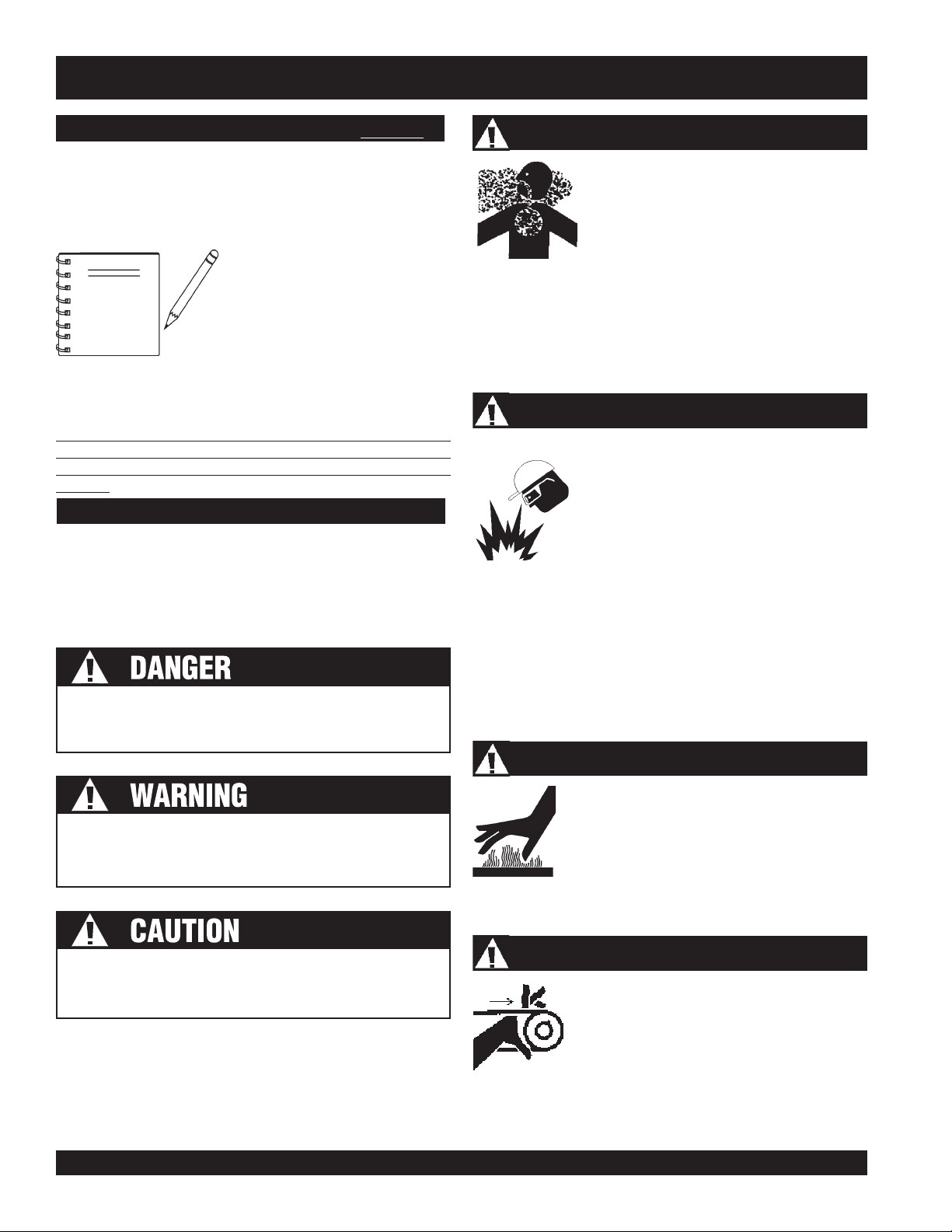
The three (3) Safety Messages shown below will inform you
about potential hazards that could injure you or others. The
Safety Messages specifically address the level of exposure to
the operator, and are preceded b y one of three words: DANGER,
WARNING, or CAUTION.
You WILL be
if you DO NOT follow these directions.
KILLED
or
SERIOUSLY INJURED
approved containers, in well-ventilated areas and away from
sparks and flames. NEVER use fuel as a cleaning agent.
Natural gas and LPG are extremely flammable and will explode
and catch fire if exposed to sparks or flame. NEVER smoke in
any area where gases are stored or supplied. IMMEDIATELY
shut off the gas source if a leak is detected. Be certain that the
area is well ventilated before exposing it to any mechanical or
electrical device that may emit heat or sparks.
Lethal Exhaust Gases
Engine exhaust gases contain poisonous
carbon monoxide. This gas is colorless and
odorless, and can cause death if inhaled.
NEVER operate this equipment in a
confined area or enclosed structure that
does not provide ample free flow air.
Natural gas and liquid petroelum gas (LPG)
Explosive Fuel
can cause an explosion if ignited.
DO NOT start the engine near spilled fuel or
combustible fluids. DO NOT fill the fuel tank
while the engine is running or hot. DO NOT
overfill tank, since spilled fuel could ignite if it
comes into contact with hot engine parts or
sparks from the ignition system. Store fuel in
Burn Hazards
Engine components can generate extreme heat.
To prevent burns, DO NOT touch these areas
You CAN be KILLED or
you DO NOT follow these directions.
SERIOUSLY INJURED
if
while the engine is running or immediately after
operation. NEVER operate the engine with heat
shields or heat guards removed.
Rotating Parts
You CAN be
these directions.
Potential hazards associated with MQ Power Gensets field
installation will be referenced with Hazard Symbols which appear
throughout this manual, and will be referenced in conjunction
with Safety Message Alert Symbols.
PAGE 6 — INDUSTRIAL GENERATOR SETS — APPLICATION & INSTALLATION MANUAL — REV. #4 (09/07/07)
INJURED
if you DO NOT f ollo w
NEVER operate equipment with covers or
guards removed. Keep fingers, hands, hair
and clothing away from all moving parts to
prevent injury.
Page 7
SAFETY MESSA GE ALERT SYMBOLS
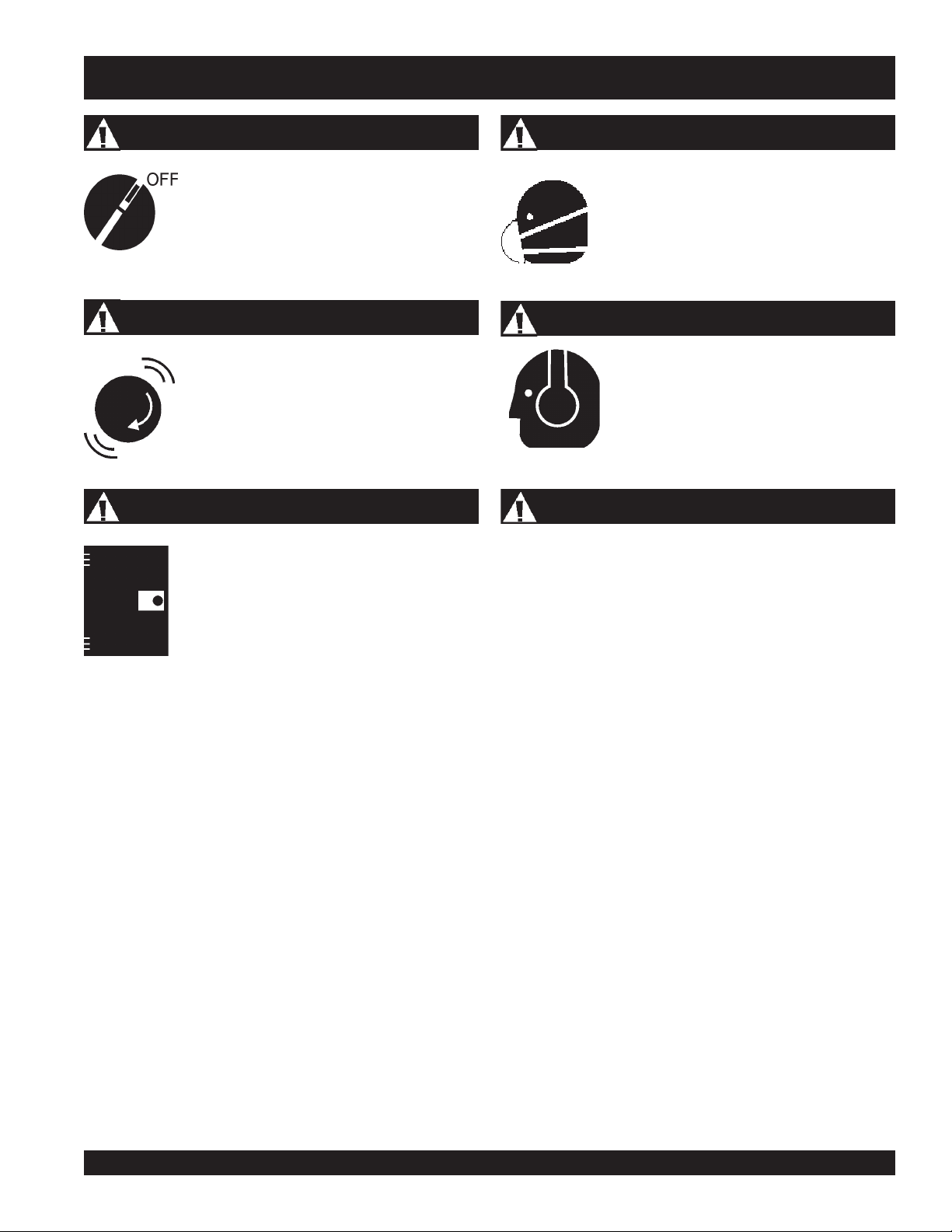
Accidental Starting
ALWAYS place the ignition switch or genset
starting device in the OFF position, remove key
and/or disconnect the battery before servicing
the engine or equipment.
Over Speed Conditions
NEVER tamper with the factory settings of the
engine governor or settings. Personal injury
and damage to the engine or equipment can
result if operating in speed ranges above
maximum allowable.
Guards and Covers In Place
NEVER operate the genset without guards and
covers in place.
Respiratory Hazard
ALWAYS wear approved respiratory protection.
Sight and Hearing hazard
ALWAYS wear approved eye and hearing
protection.
Equipment Damage Messages
Other important messages are provided throughout this manual
to help prevent damage to your genset, other property, or the
surrounding environment.
THIS MQ POWER GENSET, OTHER PROPER TY, OR THE SURROUNDING
EQUIPMENT COULD BE DAMA GED IF Y OU DO NOT FOLLOW INSTRUCTIONS
INDUSTRIAL GENERATOR SETS — APPLICATION & INSTALLATION MANUAL — REV. #4 (09/07/07) — PAGE 7
Page 8
IMPORTANT SAFETY INSTRUCTIONS
■
SAVE THESE INSTRUCTIONS — This manual
contains important safety instructions for MQ
Power Industrial generators that should be
followed during installation, operation, and
maintenance of the engine-generator set.
F ailure to follow instructions in this manual may lead to
serious injury or even death! This equipment is to be
operated by trained and qualified personnel only! This
equipment is for industrial use only.
GENERAL SAFETY
■
DO NOT install, operate , or service this
equipment before reading this entire
manual along with the operation
manual.
High Temperatures – Allow the engine to cool before
adding fuel or performing service and maintenance
functions. Contact with
burns.
■
The engine of this generator requires an adequate free
flow of cooling air. Never operate the generator in any
enclosed or narrow area where free flow of the air is
restricted. If the air flow is restricted it will cause serious
damage to the generator or engine and may cause injury
to people. The generator engine giv es off DEADLY carbon
monoxide gas.
NEVER operate
the genset in a
restricted air flow
environment!
hot
components can cause serious
■
NEVER operate this equipment without proper protective
clothing, shatterproof glasses, steel-toed boots and other
protective devices required by the job.
■
NEVER operate this equipment when not
feeling well due to fatigue, illness or taking
medicine.
■
NEVER operate this equipment under the
influence of drugs or alcohol.
■
NEVER touch the hot exhaust manifold,
muffler or cylinder. Allow these parts to cool
before servicing engine or generator .
■
■
■
■
■
DO ALWAYS refuel in a well-ventilated area, away from
sparks and open flames. Fire or explosion could result
from fuel vapors, causing severe bodily harm — even
death!
DO NOT smoke around or near the
machine. Fire or explosion could result
from fuel vapors, or if fuel is spilled on a
hot engine, causing severe bodily harm
— even
ALWAYS use extreme caution when
working with flammable liquids. When
refueling, stop the engine and allow
it to cool.
NEVER operate the generator in an
explosive atmosphere or near
combustible materials. An explosion or fire could result
causing severe
Topping-off to filler por t is dangerous, as it tends to spill
fuel.
death!
bodily harm or even death!
PAGE 8 — INDUSTRIAL GENERATOR SETS — APPLICATION & INSTALLATION MANUAL — REV. #4 (09/07/07)
Page 9
IMPORT ANT SAFETY INSTR UCTIONS
GENERAL SAFETY
■
NEVER touch output terminals during operation. This is
extremely dangerous. Always stop the machine and
disconnect the battery when contact with the output
terminals is necessar y.
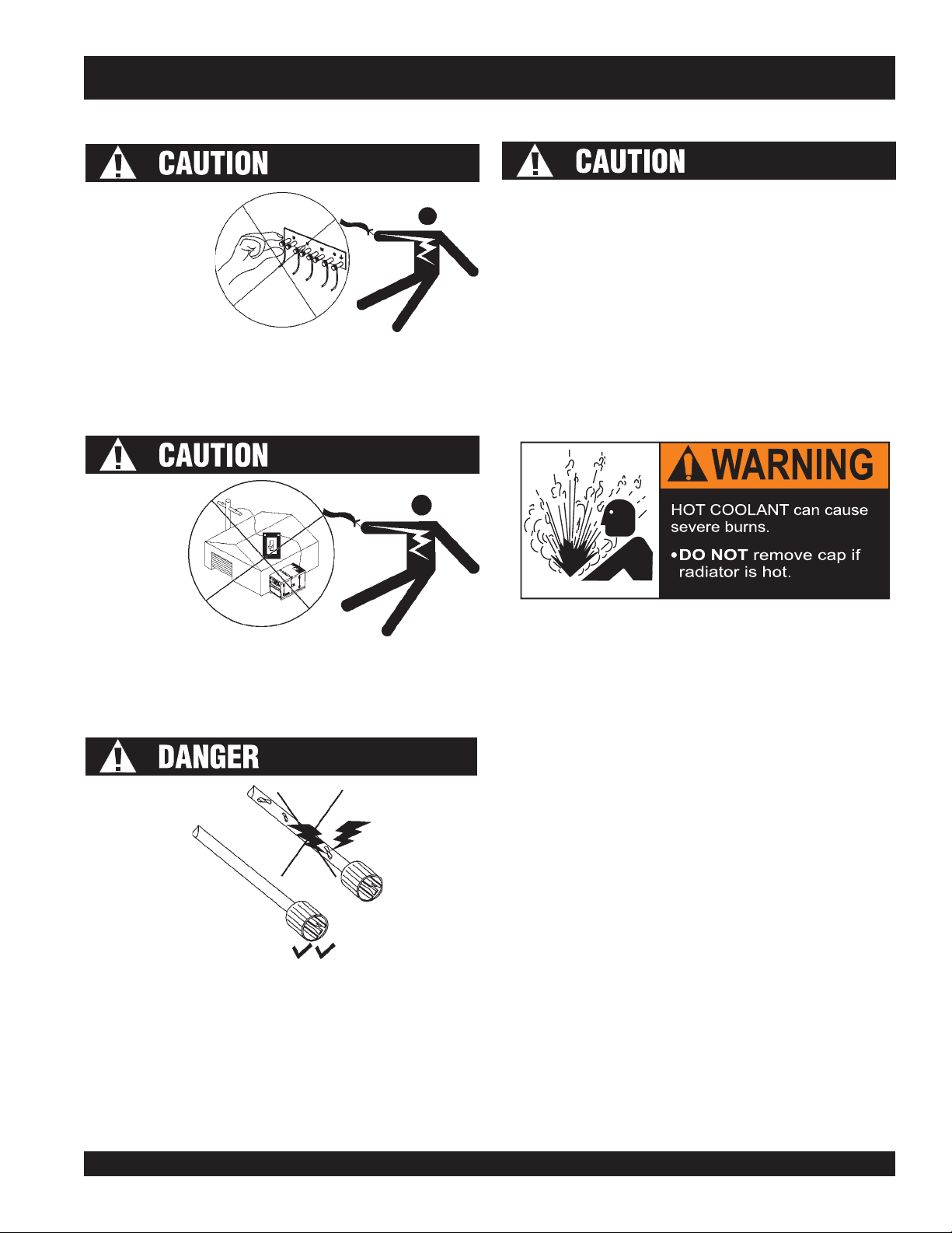
RADIAT OR
■
1. Radiator Cap - Removing the radiator cap while the
DO NOT touch or open an y of the components mentioned
below while the generator is running. Always allow
sufficient time for the engine and generator to cool before
performing maintenance.
engine is hot will result in high pressurized, boiling water
or coolant to gush out of the radiator, causing severe
scalding to any persons in the general area of the
generator .
■
NEVER connect the generator to house wiring. This is
illegal and very dangerous. Electrical shock could occur
causing damage to the generator and bodily harm — even
2. Coolant Drain Plug - Removing the coolant drain plug
death!
3. Engine Oil Drain Plug - Removing the engine oil drain
■
NEVER use damaged or worn cables when connecting
power tools or equipment to the generator. Make sure
power connecting cables are securely connected to the
generator’ s output terminals, insufficient tightening of the
terminal connections may cause arcing and damage the
generator . Touching worn or frayed electrical cables may
cause electrical shock, which could result in severe bodily
harm or even
death!
while the engine is hot will result in hot coolant to drain
out of the coolant drain plug, and could cause severe
scalding to any persons in the general area of the
generator .
plug while the engine is hot will result in hot oil to drain
out of the oil drain plug, and could cause severe scalding
to any persons in the general area of the generator .
INDUSTRIAL GENERATOR SETS — APPLICATION & INSTALLATION MANUAL — REV. #4 (09/07/07) — PAGE 9
Page 10
IMPORTANT SAFETY INSTRUCTIONS
Operation Safety
■
ALWAYS be sure the operator is familiar with proper saf ety
■
precautions and operations techniques before using
generator .
■
DO NOT allo w unauthorized people near equipment.
■
ALWAYS wear ear protection when working in
a loud environment.
■
NEVER run engine without air filter. Engine damage will
occur.
■
DO NOT leave the generator running in the MANUAL
mode unattended.
■
NEVER use accessories or attachments which are not
recommended by MQ P ower for this equipment. Damage
Maintenance Safety
When performing maintenance on MQ Po wer generator sets,
it is important to prevent automatic start-up of the unit by a
remote contact closure by disconnecting the engine battery
before servicing.
to the equipment and/or injury to user may result.
■
Manufacturer does not assume responsibility for any
accident due to equipment modifications.
■
ALWAYS check the machine for loosened par ts or bolts
before starting.
Always disconnect the battery cable negative (first) before
performing service on the generator. Reconnect battery cable
negative (last) after service is complete.
In emergencies
phone or
phone numbers of the nearest
fire department
case of an emergency .
always
know the location of the nearest
keep a phone on the job site
. This inf ormation will be invaluable in the
. Also know the
ambulance, doctor
and
Emergencies
Always be prepared for an emergency such as fire, personnel
injury , or other emergency situation. It is important to identify
all possible emergency situations and to provide adequate
prevention methods and response methods.
■
Install the appropriate fire extinguishers in convenient
locations. Consult the local fire department for the correct
type of extinguisher to use. DO NOT use foam on
electrical fires. Use extinguishers that are rated ABC by
the National Fire Protection Association (NFPA).
■
ALWAYS know the location of the
nearest
fire extinguisher
.
■
Keep the machinery in proper running condition.
■
NEVER lubricate components or attempt service on a
running machine.
■
Always allow the machine a proper amount of time to
cool before servicing.
■
Fix damage to the machine immediately and always
replace broken parts.
■
Dispose of hazardous waste properly. Examples of
potentially hazardous waste are used motor oil, coolant,
fuel, and fuel filters.
■
DO NOT use plastic containers to dispose of hazardous
waste.
■
■
ALWAYS know the location of the nearest
first aid kit
■
ALW AYS pro vide an emergency escape route in the event
.
DO NOT pour waste , oil, coolant or fuel directly onto the
ground, down a drain, or into any water source
■
Whene ver necessary , replace nameplate, operation and
safety decals when they become difficult read.
of an emergency.
■
Never leave rags or tools on or near the generator-set.
■
Refer to the
Volvo Engine Owner's Manual
for engine
technical questions or information.
PAGE 10 — INDUSTRIAL GENERATOR SETS — APPLICATION & INSTALLATION MANUAL — REV. #4 (09/07/07)
Page 11
IMPORT ANT SAFETY INSTR UCTIONS
Battery Safety
The battery is a major component of the engine-generator
set. The genset will not start without a properly maintained
battery . Disconnecting the battery prevents the engine from
starting. Always observe the following safety guidelines
when interaction with the battery is necessary. Servicing of
batteries should be performed by authorized personnel only .
1. Wear full eye protection and protective clothing, including
rubber gloves and boots when handling a battery.
2. Remove watches, rings or other metal objects when
handling a battery .
3. Use tools with insulated handles.
4. In case the battery liquid (dilute sulfuric acid) comes in
contact with
with plenty of water and discard clothing.
5. In case the battery liquid (dilute sulfuric acid) comes in
contact with your eyes, rinse eyes immediately with
plenty of water for fifteen minutes, then contact the
nearest doctor or hospital, and seek medical attention.
6. Spilled electrolyte is to be washed down with an acid
neutralizing agent. A common practice is to use a
solution of one pound (500 grams) bicarbonate of soda
to one gallon (4 liters) of water . The bicarbonate of soda
solution is to be added until the evidence of reaction
(foaming) has ceased. The resulting liquid is to be
flushed with water and the area dried.
7. DO NOT expose the battery to open flames, sparks,
cigarettes etc. The battery contains
combustible gases and liquids. If these
gases and liquids come in contact with a
flame or spark, an explosion could occur .
8. DO NOT lay tools or metal parts on top of batter ies.
9. DO NOT drop the battery; there is the risk the battery
may explode.
10. ALWAYS discharge static electricity from the body
before touching batteries by first touching a grounded
metal surface.
clothing or skin
, rinse skin immediately
14. Only use a battery that is in proper working condition.
Replace battery as recommended by manufacturer .
The battery contains electrolyte which is a dilute sulfuric
acid that is harmful to the skin and eyes. Electrolyte is
electrically conductive and very corrosive.
The installation of the engine-generator set must provide
enough ventilation to ensure that gases generated by vented
batteries during charging, or caused by equipment
malfunction are removed.
risk of fire because they generate hydrogen gas.
If using a serviceable battery, ne v er ov er fill the battery with
water above the upper limit.
Always disconnect a battery charger from its AC source
before disconnecting the battery cables. Failure to do so
can result in voltage spikes high enough to damage the genset
DC control circuits and charger .
Make certain the battery is well-ventilated before servicing.
Arcing can ignite explosive hydrogen gas given off by batteries,
causing severe personal injury. Arcing can occur when the
cable is removed or reattached, or when negative (-) battery
cable is connected and a tool used to connect or disconnect
positive (+) battery cable touches the frame or other grounded
metal that is part of the set. Alwa ys remo ve negative (-) cable
first, and reconnect it last. Make certain hydrogen gas from the
battery, engine fuel, and other explosive fumes are fully
dissipated. This is especially important if the battery has been
connected to a battery charger.
Lead-acid batteries present a
11. ALWAYS keep the battery charged. If the battery is not
charged a buildup of combustib le gas will occur.
12. ALWAYS keep battery charging and booster cables in
good working condition. Repair or replace all worn cables.
13. ALWAYS recharge the battery in an open air environment,
to avoid risk of a dangerous concentration of combustible
gases.
INDUSTRIAL GENERATOR SETS — APPLICATION & INSTALLATION MANUAL — REV. #4 (09/07/07) — PAGE 11
On generators not having a grounded supply circuit,
determine if the battery is inadver tently grounded. When
inadvertently grounded, remove source of ground. Contact
with any part of a grounded battery is capable of resulting in
electrical shock. The risk of such shock is reduced when
such grounds are removed during installation and
maintenance.
Page 12

IMPORT ANT SAFETY INSTR UCTIONS
Fire Protection
■
The design, selection, and installation of fire protection
systems is beyond the scope of this manual because of the
wide range of factors to consider . In general, ev ery possible
measure should be taken to prevent fire hazards and to
protect property and people. Consider the follo wing:
■
A protection system must comply with the requirements
of the authority having jurisdiction. This could include
the building inspector , fire marshal, or insurance carrier.
■
In general, the generator room will be required to have a
one hour fire resistance rating. If the generator set will
be in a Level 1 (life safety) application, as defined by
NFPA 110, the generator room construction will have a
two hour resistance rating.
■
The generator room should not be used for storage
purposes.
■
Generator rooms should be classified as hazardous
locations (as defined by the NEC) solely by reason of
the engine fuel.
■
The authority having jurisdiction will usually classify the
engine as a low heat appliance when use is only brief,
infrequent periods.
■
The authority having jurisdiction may specify the quantity ,
type, and sizes of approved portable fire extinguishers
required for the generator room.
The authority having jurisdiction may have more stringent
restrictions on the amount of fuel that can be stored inside
the building than published in national standards.
■
Fuel tanks located inside buildings and above the lowest
story or basement should be diked in accordance with
NFPA standards.
■
The genset should be exercised periodically under at least
30% load until it reaches stable operating temperatures
and run under nearly full load at least once a year to
prevent fuel from accumulating in the exhaust system.
■
Properly store fuel, batteries, and other fire hazardous
material.
■
The genset should be inspected regularly for fire hazards.
■
When open bottom generator is used, it is recommended
the assembly be installed over noncombustible materials
and located in such a manner such that it prevents a
combustible materials from accumulating under the
generator set.
■
Installation should provide a safe easy method to clean
up spilled engine fluids.
■
Post NO SMOKING signs near generator set, battery
storage, and fuel storage areas.
■
Install the appropriate fire extinguishers in convenient
locations. Consult the local fire department for the correct
type of extinguisher to use. DO NOT use foam on
electrical fires. Use extinguishers that are rated ABC
by the NFPA.
■
Use dry chemical, foam, or carbon dioxide (CO
extinguishers on battery fires.
■
A manual EMERGENCY STOP station outside the
generator room or remote from a generator set in an
outside enclosure is recommended for shutting down the
generator set in the event of a fire or other type of
emergency.
PAGE 12 — INDUSTRIAL GENERATOR SETS — APPLICATION & INSTALLATION MANUAL — REV. #4 (09/07/07)
) fire
2
Page 13

IMPORT ANT SAFETY INSTR UCTIONS
Lifting the Generator Set
■
Before lifting, make sure the generator's lifting devices
are secure and that there is no apparent damage to the
generator itself (loose screws, nuts and bolts). If any
part is loose or damaged, please take corrective action
before lifting.
■
Always drain fuel prior to lifting.
■
Always make sure crane or lifting device has been
properly secured to the hook of guard frame on generator .
■
NEVER lift the machine while the engine is running.
■
Use adequate lifting cable (wire or rope) of sufficient
strength.
■
When lifting the generator, always use the balanced
center-point suspension hook and lift straight upwards.
■
NEVER allow any person or animal to stand underneath
the machine while lifting. Make sure the lifting path of
the generator set is clear before moving.
■
When loading the generator on a truck, be sure to use
the front and back frame bars as a means to secure the
generator during transport.
■
Do not lift the generator set by the lifting eyes attached
to the engine and/or alternator. These lifting eyes are
used only during generator assembly and are not capable
of supporting the entire weight of the genset.
■
A four-point lifting method is necessary to lift the genset.
To maintain generator balance during lifting, the lifting
apparatus must utilize the four skid lifting holes. One
method of lifting the genset uses an apparatus of hooks
and cables joined at a single rigging point. The use of
spreader bars is necessary with this method to avoid
damage to the set during the lifting procedure. The
spreader bars should be slightly wider than the genset
skid so the set is not damaged by lifting cables and only
vertical force is applied to the skid while lifting. The
genset may also be lifted by placing bares through the
skid lifting holes and attaching hooks to the end of the
bars. Be sure all lifting equipment is properly sized for
the weight of the genset.
Transporting
■
Always shutdown engine before transporting.
■
Nev er transport generator with air intake doors open.
■
Tighten fuel tank cap securely.
■
Drain fuel when transporting generator over long distances
or bad roads.
■
Always tie-down the generator during transportation by
securing the generator.
■
If the generator is mounted on a trailer, make sure the
trailer complies with all local and state safety
transportation laws. See the operation manual for towing
procedures.
■
The transporting vehicle/trailer must be sized for the
dimension and weight of the genset. Consult the set
dimensional drawing or contact the factory for information
(weight, dimensions) pertinent to planning transport. The
overall height of a generator set in transit (including
vehicle/trailer) must not exceed 13.5 ft (4.1 m) unless
special hauling permits are obtained (check Federal,
State, and local laws prior to transporting). Larger units
(above 1000 kW) should be tr ansported on low-boy-type
trailers with a deck height of 25 in. (635 mm) or less to
meet clearance requirements. Large (unboxed) generators
with radiators should be loaded with the radiator facing
the rear to reduce wind resistance while in transit.
Radiators with free-wheel fans must have the fan secured
to prevent rotation that might introduce flying objects to
the radiator core or fan blades.
■
Even the heaviest of units is capable of movement
during shipment unless properly secured. Fasten the
set to the vehicle/trailer bed with properly sized chain
routed through the mounting holes of the skid. Use chain
tighteners to remove slack from the mounting chain.
Cover the entire unit with a heavy-duty tarpaulin and
secure tarpaulin to the genset or trailer as circumstances
dictate.
INDUSTRIAL GENERATOR SETS — APPLICATION & INSTALLATION MANUAL — REV. #4 (09/07/07) — PAGE 13
Page 14

INTRODUCTION
Introduction
Engine-Generator sets provide emergency power in the event
of utility power failure, provide power where utility power is
not available and can provide an alternative power means in
areas where utility power may be more expensive.
Part of the reason for the growing emphasis on emergency/
standby power systems is the proliferation of electronic
computers in data processing, process control and life
support systems, and any other system that requires a
continuous, uninterrupted flow of electrical energy . Gener ator
sets must be applied in such a way as to provide reliable,
electrical power of the
About This Manual
This manual provides specific recommendations for
installation of MQ Power's Industrial generator sets
(gensets). This manual will contain the f ollowing information:
1. Application — This section provides information on
sizing the correct generator set, determining load
characteristics, and environmental considerations.
2. Mounting Recommendations — This section pro vides
mounting recommendations such as typical fastening,
footing, foundations, proper space requirements, and
vibration isolation.
3. Mechanical Connections — This section provides
typical information regarding the fuel system, battery
system, exhaust system, proper ventilation, and proper
cooling.
4. Ventilation and Cooling — This section shows diff erent
installation methods for ventilating and cooling the
genset.
quality
and
capacity
required.
Safety Considerations
MQ Po wer's gensets have been carefully designed to provide
safe and efficient service when properly installed, maintained,
and operated. However, the overall safety and reliability of
the complete system is dependent on many factors outside
the control of the generator set manufacturer. This manual
is provided to illustrate recommended electrical and
mechanical guidelines for a safe and efficient installation.
All systems external to the generator (fuel, exhaust,
electrical, etc.) must comply with all applicable codes. Make
certain all required inspections and test have been
completed and all code requirements have been satisfied
before certifying the installation is complete and ready for
service.
Always remember: SAFETY FIRST!!! Safety involves two
aspects: safe operation of the generator set itself (and its
accessories) and reliable operation of the system. Reliable
operation of the system is related to safety because
equipment affecting life and health, such as life-support
equipment in hospitals, emergency lighting, building
ventilators, elevators, and fire pumps may depend upon the
generator set.
In North Amer ica, many safety (and environmental) issues
related to generator set applications are addressed by the
following standards of the National Fire Protection
Association (NFPA):
z
Flammable and Combustib le Liquids Code — NFPA 30
z
National Fuel Gas Code — NFPA 54
z
National Electrical Code — NFPA 70
z
Health Care Facilities Code — NFPA 99
z
Life Safety Code — NFPA 110
z
Emergency and Standby P ower Systems — NFPA 110
z
Storage and Handling of Liquified Natural Gas —
NFPA 59A
Many national, state, and local codes incorporate the above
5. Electrical Connections — This section provides the
location of electrical connection points for DC Controls,
AC electrical connections, and system & equipment
grounding.
6. Pre-Start Preparation — Checklist of items or
procedures needed to prepare the generator set for
operation.
PAGE 14 — INDUSTRIAL GENERATOR SETS — APPLICATION & INSTALLATION MANUAL — REV. #4 (09/07/07)
standards (and others) by reference. Each of these
standards and the codes that reference them are periodically
updated, requiring continual review. Compliance with all
applicable codes is the responsibility of the facility design
engineer. For example, some areas may have certificateof-need, zoning permit, building permit, or other site specific
requirements. Be sure to check with all local governmental
authorities before designing the generator set installation.
Page 15

INST ALLA TION O VERVIEW
Overview
These installation recommendations apply to typical
installations with standard model gensets. Whenever
possible, these recommendations also cover factory
designed options or modifications. However, because of
the large amount of variables involved with any installation,
it is not possible to provide specific recommendations for
every possible situation.
This manual
information for selecting a genset or designing the complete
installation.
are any questions not answered by this manual, contact
your nearest MQ P o wer dealer or distributor f or assistance .
Application and Installation
A standby power system must be carefully planned and
correctly installed for proper operation. This involves two
essential elements of application and installation.
Application
Application as it applies to genset installations refers to the
design of the complete standby power system. Such an
effort usually considers power distribution equipment, transf er
switches, ventilation equipment, and mounting pads.
Consideration is also given to cooling, exhaust, and fuel
systems.
Each subsystem must be correctly designed so the
complete system will function as intended. Application and
design is an engineering function generally done by specifying
engineers or other trained specialists. Specifying consulting
engineers are responsible for the designing the complete
standby system and for selecting the materials and products
to be used.
Installation
Installation refers to the actual setup and assembly of the
standby power system. The installers, usually licensed
contractors, set up and connect the various components of
the system as specified in the system design plan. The
complexity of the standby system normally requires the
special skills of qualified electricians, plumbers, sheet metal
workers, construction workers, etc. to complete the various
segments of the installation. This is necessary so all
components are assembled using standard methods and
practices.
does not
This manual is a reference tool only
provide complete application
. If there
Selection and Application
Generator set size and site location should be considered
in the preliminary design and budget estimate. The
generator size should be selected according to the required
load. Choosing a mounting site located inside the building
or outside in a shelter or housing will help determine how
the genset will be installed and what specific issues need to
be addressed.
Sizing
It is important to assemble a reasonably accurate load
schedule as soon as possible for budgeting project costs.
If all the load equipment information needed for sizing is not
available early in the design planning, estimates and
assumptions will have to be made during the preliminary
calculation in order to account for all needed pow er . When
all the information becomes available, it is important to
recalculate the sizing requirements to ensure reliable
operation.
Large motor loads, uninterrupted power supplies (UPS),
variable frequency drives, and medical diagnostic imaging
equipment have a considerable effect on the generator set
sizing and should be considered closely. Too, the required
power to start a motor can be considerably larger than the
power required to maintain the load.
Fuel Requirements
Diesel engine generator sets are recommended for
emergency/standby applications. Premium No. 2-D Grade
diesel fuel is recommended for performance and engine life.
On-site fuel storage must be provided. The storage life for
diesel fuel is up to two years when stored properly. Proper
supply tank sizing should allow fuel turnover based on
scheduled ex ercise and test periods. To avoid condensation
mixing with the fuel, do not provide a fuel tank that is too
large. A microbicide may be required if fuel turnover is low
or conditions promote the growth of microbes in the fuel.
Always consider emissions requirements when designing
the fuel and exhaust system. Refer to the Fuel System
section for more information.
INDUSTRIAL GENERATOR SETS — APPLICATION & INSTALLATION MANUAL — REV. #4 (09/07/07) — PAGE 15
Page 16

INST ALLA TION O VER VIEW
Cold Climates and Derating Factors
Extreme temperature and high elevation effect the efficiency
of the engine-generator set. Always take into account
derating factors of climate and elevation when sizing a
generator set.
Use Premium No.1-D Grade diesel fuel when the ambient
temperature is below freezing. Fuel heating may be required
to prevent fuel filters from clogging when temperatures fall
below the cloud point of the fuel at approximately 20°F
(-6°C) for No . 2-D and -15°F (-26°C) f or No . 1-D .
Location
Location of the generator set will determine the cost
effectiveness of an installation. The generator set can be
located inside a building or outside the building with a shelter
or weather-protective housing. The location will help
determine the layout of the fuel tanks, louvers, ventilation
ducts, accessories, etc. Consider the following when
deciding where to locate the generator set:
Safety considerations
Noise. See pages 27 thru 32 for environmental
considerations.
Ambient temperature
Mounting
Fuel, exhaust, ventilation, and cooling systems
Location of the distribution switchboard and transfer
switch
Branch circuits for coolant heaters , battery charger, etc.
Security from flooding, fire, icing, and vandalism
Containment of accidentally spilled or leaked fuel or
engine fluids
Mounting - Ensure generator is located (mounted) over
non-combustible materials and is situated in such a
manner as to prevent combustible materials from
accumulating under the generator .
Indoor Locations
Dedication of room for the generator sets only. For
emergency power systems, codes may require the
generator room be dedicated for that purpose only . Also
consider the effect of the large ventilation air flows would
have on other equipment in the same room.
Fire rating of the room construction. Most codes specify
a 1 or 2 hour rating. Check with the local fire authority
for code guidelines.
Working space. Working space around electrical
equipment is usually specified by code. There should
be at least four feet (1200 mm) of clearance around
each generator set. The generator should be accessib le
for service without removing the set or any accessories.
Type of cooling system. A factory-mounted radiator is
recommended.
V entilation. Large volumes of air flow are inv olved. Room
ventilation fans might be required for a heat exchanger
or remote radiator configurations.
Engine exhaust. The engine exhaust outlet should be
as high as practical on the downwind side of the building
and away from vents and building openings.
Fuel storage and piping. Codes may restrict fuel storage
inside buildings. It is important to consider a safe method
for refueling the fuel tank. Check with the local fire
authority for code guidelines.
Outdoor Locations
Airborne noise. Locate and/or route engine exhaust
piping away from nearby windows & doorways.
Outdoor enclosures. Give consideration to type of
outdoor housing, including weather-protective and/or
sound attenuated types.
Security. Consider use of security fences and site
barriers.
Property line distances. Ensure before proceeding with
final installation plans you are aware of your property
lines.
Engine exhaust. Engine exhaust must be routed away
from building intake vents, windows, doorways and other
openings.
PAGE 16 — INDUSTRIAL GENERATOR SETS — APPLICATION & INSTALLATION MANUAL — REV. #4 (09/07/07)
Page 17
GENSET SIZING
Generator Set Sizing Calculations
The generator set must be sized to supply the maximum
starting (power surge) demands and the steady-state running
loads of the connected equipment.
It is important to have the correct generator to meet the
demands of the starting kVA (SkVA), star ting kW (SkW),
running kVA (RkVA) and running kW (RkW). A value for
generator kW (GkW) is also obtained when nonlinear loads
are included in the sizing calculation.
Once the starting and running loads have been determined,
it is typical to add a margin factor of up to 25% for future
expansion or to select a generator set of the next largest
The use of closed-transition autotransformer starters for
reduced voltage starting of large motor loads will reduce the
size of the generator set required relative to across-the-line
starting. Resistor-type reduced-voltage motor starting may
actually increase the size of the generator set required due
to high starting power factors. Wound rotor motors are the
easiest type of motor for a generator set to start.
The first step is to create a reasonably accurate schedule
of connected loads as early in the preliminary design as
possible. A sample load schedule sheet can be found below
on T able 1.
Genset Sizing Procedure
standard rating. A large connected load that does not run
during usual power outages, such as a fire pump, can serve
as part of a margin factor. For a fuel efficiency standpoint,
the running load should stay within approximately 50 to 80%
of the generator kW rating. To avoid "wet stacking", the
running load should not be less than 30% of the generator
set rating.
When calculating the generator size needed for the
application, consider the following procedure:
Step 1. Prepare a load schedule
Step 2. Enter loads in step sequence on the worksheet
Step 3. Enter individual load characteristics on the
It may be necessary to oversize a generator set in
applications where the voltage and frequency dip
performance specifications are more stringent than usual,
particular ly when large motors are started across-the-line
or UPS equipment is involved. Applications that involve
any of the following nonlinear loads may also make it
necessary to oversize the generator set or the generator:
Static Uninterrupted Power Supplies (UPS)
Battery Charging Rectifiers (T elecommunications)
V ariable Frequency Driv es (VFD)
Medical Diagnostic Imaging Equipment
Step 4. Find the load step totals
Step 5. Select a generator set
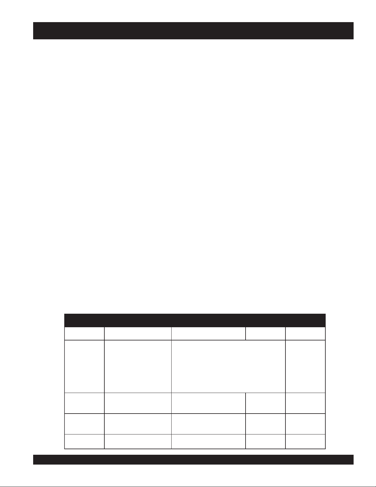
Step 1. Prepare a Load Schedule
All the loads that will be connected to the generator set
should be recorded on the load schedule. Identify each
load as to type, power rating, and quantity. See Table 1
below for the loads listed (in
calculation.
worksheet
italics
) for an example
eludehcSdaoL.1elbaT
#daoLnoitpircseDdaoLdaoLfoepyTgnitaRrewoP.YTQdaoL
:selpmaxE
Wk...................................gnithgiL
AVk..............................SPUcitatS
PH............sevirDdeepSelbairaV
AVk.............srefitceRCDmoceleT
PH.....................................srotoM
1
2
3
INDUSTRIAL GENERATOR SETS — APPLICATION & INSTALLATION MANUAL — REV. #4 (09/07/07) — PAGE 17
2#&1#spmuPretaW,GretteledoCameN,rotoM
)paT%08(retratsremrof
3#spmuPretaW,GretteledoCameN,rotoM
)paT%08(retratsremrof
gnithgiLtnecsroulFgnithgiLPH01
PH001
PH001
2
1
1
Page 18

GENSET SIZING
Generator Set Sizing Calculations (Continued)
Step 2. Create a Generator Set Worksheet
a. When creating a worksheet, number a worksheet for each
sequenced load step. The n umber block is in the upper
right hand corner of the wor ksheet. Worksheet #1 will
coincide with Load Step #1, Worksheet #2 will coincide
with Load Step #2, and etc.. The
will provide additional information to be followed here.
The worksheets need not have load step numbers unless
starting is sequential.
b. Enter the individually assigned load numbers (load
schedule) onto the appropriate generator set sizing
worksheet. That is, all the load n umbers for load step #1
should be entered on worksheet #1, for load step #2 on
worksheet #2, and etc.
c. For each load, enter the
schedule in the column labeled
Figure 1 on page 19 is an example load calculation for an
application involving a two-step load starting sequence.
Because the application is a two-step load starting
sequence, it requires two worksheets as shown. The entries
are in
italics
.
step sequence guidelines
Load QTY
marked on the load
QTY
on the worksheet.
Step Sequence Guidelines
Single Step, Simultaneous Starting — One commonly
used approach is to assume that all connected loads
will be started simultaneously in a single step, regardless
of the number of transf er switches used. This approach
assures that the genset is properly sized to meet the
entire load demand and is the most conservative
method.
Single Step, with Diversity F actor — This is similar to
simultaneous starting in a single step, except that an
estimated diversity factor, of perhaps 80 percent, is
applied to reduce the starting kVA (SkVA) and starting
kW (SkW) totals to account for whatever automatic
starting controls may be provided with the load
equipment.
Multiple Step Sequence — Sequenced starting of
loads (where possible) will often permit the most precise
load demand for selecting a generator .
A step sequenced start may be approximated, for e xample,
by dividing the loads into blocks each served by a separate
transfer switch and then using the standard time delay on
transfer to stagger connection of each block onto the
generator set. However, once all of the loads have been
brought up on line with the genset, the load equipment may
be frequently started and stopped by automatic controls. In
such cases, the genset will have to be sized to start the
largest motor last, with all other connected loads on line.
Consider the following when controls or delays are provided
to step sequence the loads onto the generator set:
Start the largest motor first. Use only when on a manual
starting system.
Load the UPS last. UPS equipment is typically frequency sensitive, especially to the rate of change of
frequency. A pre-loaded genset will be more stable in
accepting the UPS load.
PAGE 18 — INDUSTRIAL GENERATOR SETS — APPLICATION & INSTALLATION MANUAL — REV. #4 (09/07/07)
Page 19
GENSET SIZING
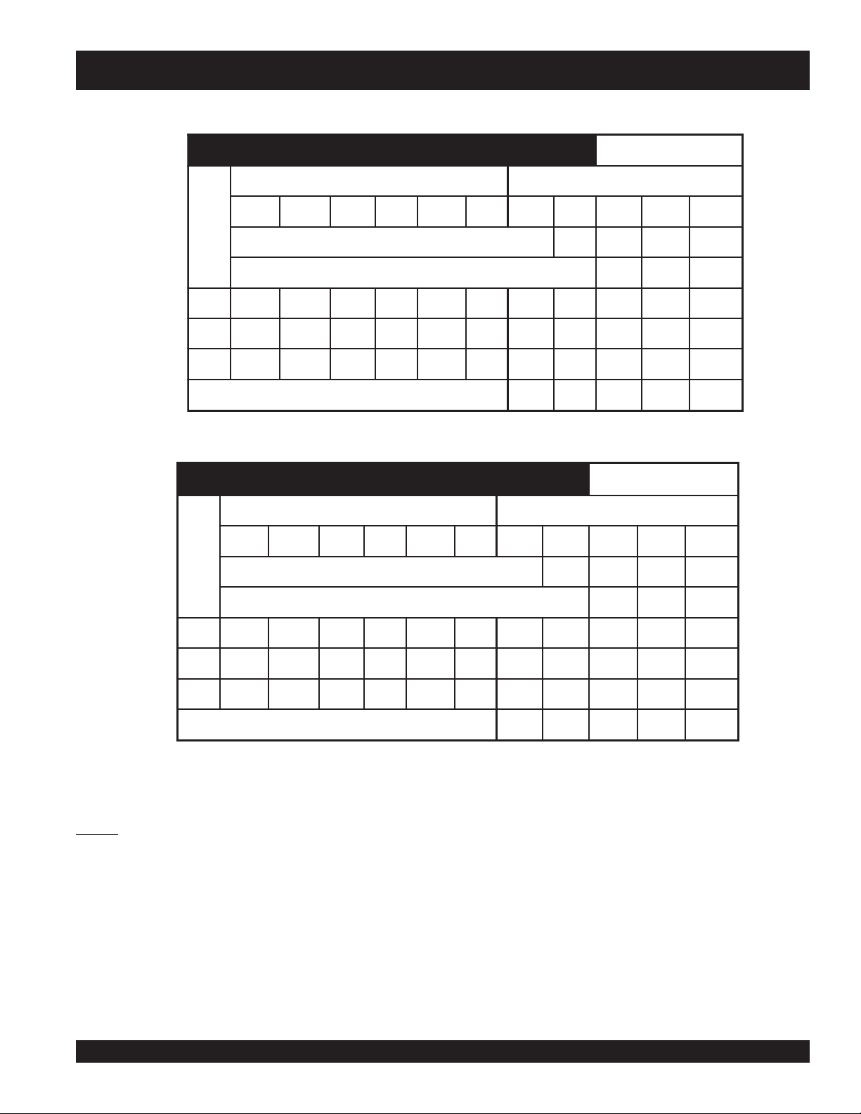
teehskroWgniziSteSrotareneG 1#petSdaoL
scitsiretcarahCdaoLlaudividnIslatoTpetSdaoL
AVkSWkSAVkRWkRWkGYTQAVksWksAVkRwkRwkG
>---petsdaolsuoiverpmorflatotWkRretnE—
daoL
#
.16.773
a
b
3.311
d
98
c
9.18
e
9.18
2
.3—————1 5.01
-.557
f
2
g
—— ————————— —
--petsdaolsuoiverpmorfslatotWkGdna,WkR,AVkRretnE
—— —
>-
f
822
g
01
f
871
g
5.01
8.361
g
01
-e
f
8.361
f,
e
01
>--------------------------slatoTpetSdaoL
8325.8818.3718.371
7.567
teehskroWgniziSteSrotareneG 2#petSdaoL
scitsiretcarahCdaoLlaudividnI
AVkSWkSAVkRWkRWkGYTQAVksWksAVkRwkRwkG
8.371
---petsdaolsuoiverpmorfslatotWkGdna,WkR,AVkRretnE
>
h
9.18
5.8818.3718.371
h
98
h
9.18
h
8.361
daoL
#
.2—————198
—— —————
———— —
>---petsdaolsuoiverpmorflatotWkRretnE
h
—— ———————— — —
>--------------------------slatoTpetSdaoL
98
7.5525.7727.5526.733
Figure 1. Genset Sizing Worksheets
(Example Two-Step Loading Application)
NOTES:
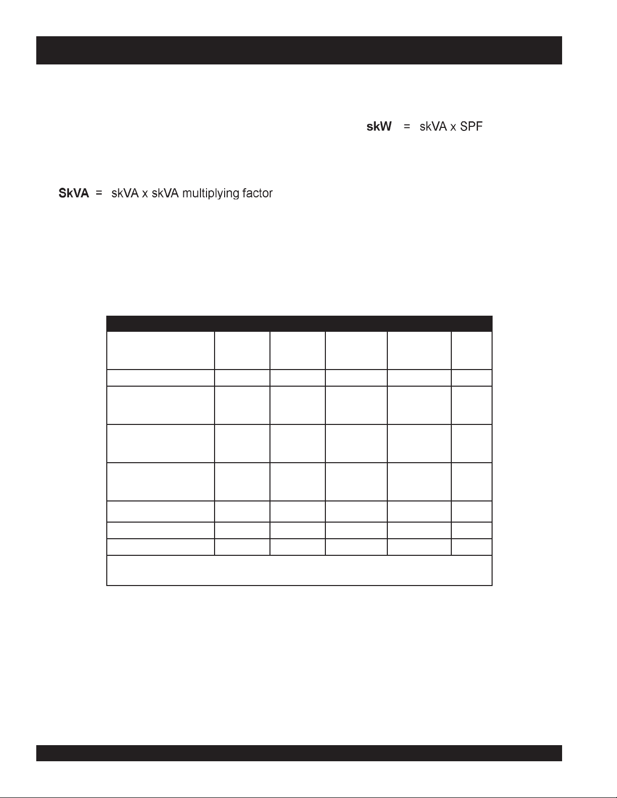
a. For the two 100 HP motors, SkVA = HP x NEMA Code Letter Multiplier (Tab le 6) = 100 x 5.9 x 0.64 = 377.6
b. SkW = SkV A x SPF = 377.6 x 0.3 =113.3
c. RkW = HP x 0.746 / 0.91 = 81.9
d. RkV A = RkW / RPF = 81.9 / 0.92 = 89
e. A GkW total will need to be found because Load #2 is a nonlinear load. Therefore , enter values f or GkW f or the linear loads. GkW= RkW for
linear loads.
f. These values are twice the values in the
individual load characteristics
columns because QTY is 2 for Load #1.
g. For the fluorescent lighting, RkW = SkW . SPF and RPF both = 0.95
h. For the 100 HP VFD motor: GkW = RkW x generator sizing f actor = 81.9 x 2.0 = 163.8; SkW = RkW; and SkVA = RkVA.
INDUSTRIAL GENERATOR SETS — APPLICATION & INSTALLATION MANUAL — REV. #4 (09/07/07) — PAGE 19
Page 20

GENSET SIZING
Generator Set Sizing Calculations (Continued)
Step 3. Enter Individual Load Characteristics
a. Calculate the values for SkVA, SkW, RkVA, and RkW
and then enter the values on the worksheets. See
determining load characteristics
instructions on how to calculate the values for various
types of loads.
b. If the load quantity (QTY) is one, enter the values for
SkVA, SkW, RkVA, and RkW directly onto the columns
under the
c. If the load quantity is greater than one, enter the values
for SkVA, SkW, RkVA, and RkW in the columns under
the
each load entry by the number under QTY and enter the
products under the
SkW, RkVA, and RkW.
d. If nonlinear loads are included, calculate a GkW value
for each nonlinear load and enter it under the GkW
column. Follow the guidelines in part C above for m ultiple
nonlinear loads.
load step totals
heading.
individual load characteristics
load step totals
on page 22 for
heading. Then multiply
heading for SkVA,
Step 4. Enter Individual Load Characteristics
Now all the loads on the
the
generator set sizing worksheets
characteristics should be calculated and entered on the
worksheets, and the worksheets numbered in load step
sequence.
Referring back to Figure 1, find the load step totals as
follows:
a. Starting with worksheet #1 (Load Step #1), add the
entries in each column under the
and enter the sums on the
b. On worksheet #2 enter the
worksheet #1 as instructed on the worksheet.
c. Repeat steps a and b as necessary through all the
worksheets.
d. Go back through all the worksheets and highlight or circle
the highest load step total of SkVA, SkW, RkVA, RkW,
and GkW. Generator set selection will be based on
these values.
load schedule
should be listed on
load step totals
load step totals
load step totals
, all the load
heading
line.
from
e. In order to obtain a total GkW in applications that include
linear as well as nonlinear loads, enter the values for
RkW for all the linear loads under GkW as well (RkW =
GkW for linear loads only).
PAGE 20 — INDUSTRIAL GENERATOR SETS — APPLICATION & INSTALLATION MANUAL — REV. #4 (09/07/07)
Page 21

Generator Set Sizing Calculations (Continued)
Step 5. Select a Generator Set
a. Establish the minimum size required
i. At this point the addition of future loads should be
considered. The RkW and RkVA values that were
highlighted or circled in Step 4 (previous page)
should be multiplied by a factor representing your
best judgement.
ii. Referring to the genset specification sheets, pick
the generator set model having a kW/kVA rating
that meets the highest RkW and RkVA totals
highlighted or circled in Step 4. Use the values
calculated for RkW and RkVA in sub-step i above if
the future addition of load was factored in.
iii. In addition to the specification sheet, the motor
starting curve should be referenced. Make sure to
take into account any derating factors such as high
altitudes or ambient temperature.
b. In applications where it is necessary to limit transient
voltage dip to approximately 10 to 20 percent of nominal
voltage, multiply the SkVA highlighted or circled in Step
4 by at least 1.25. Repeat the selection steps above.
A transient voltage dip of approximately 20 to 40% can
c. In applications where GkW has been determined (Step
4) and where GkW is greater than the kW rating of the
generator set that has been selected, an alternator (AC
generator) must be picked for the set which has a kW
rating equal to or greater than GkW.
i. See the alternator data sheet for the alternator
ii. If GkW is too high for the alternator selected to meet
iii. If none of the alternators available for the generator
be expected when the genset selected is only slightly
greater than the maximum SkVA. The actual transient
voltage dip is a function of several factors and is difficult
to determine accurately .
GENSET SIZING
temperature rise. Compare GkW to the alternator
kW rating at the appropriate voltage. The greater
the voltage, the greater the kW rating.
the temperature rise specifications (if any), find the
alternator data sheet for the alternator specified for
the next lower temperature rise. Compare GkW to
the alternator kW rating at the appropriate voltage.
Repeat the procedure with any other models. If there
are no generator temperature rise specifications that
have to be met, consider comparing GkW to the
kW rating at the higher temperature rise rating of
125°C.
set has a kW rating sufficient to meet GkW, refer to
the specification sheet for the next larger size
generator set and repeat the selection process.
NOTE
INDUSTRIAL GENERATOR SETS — APPLICATION & INSTALLATION MANUAL — REV. #4 (09/07/07) — PAGE 21
The running load should not be
less then 30 percent of the
generator set rating.
Page 22
GENSET SIZING — DETERMINING LO AD CHARACTERISTICS
Determining Load Characteristics
Lighting
For all types of lighting loads:
RkW = The sum of the r ated watts of all lamps and ballasts.
Single-Phase Induction Motor
For 1Ø motors, use the SkVA, SkW, RkVA, and RkW values
in Table 4 below that correspond to the motor nameplate
horsepower and type.
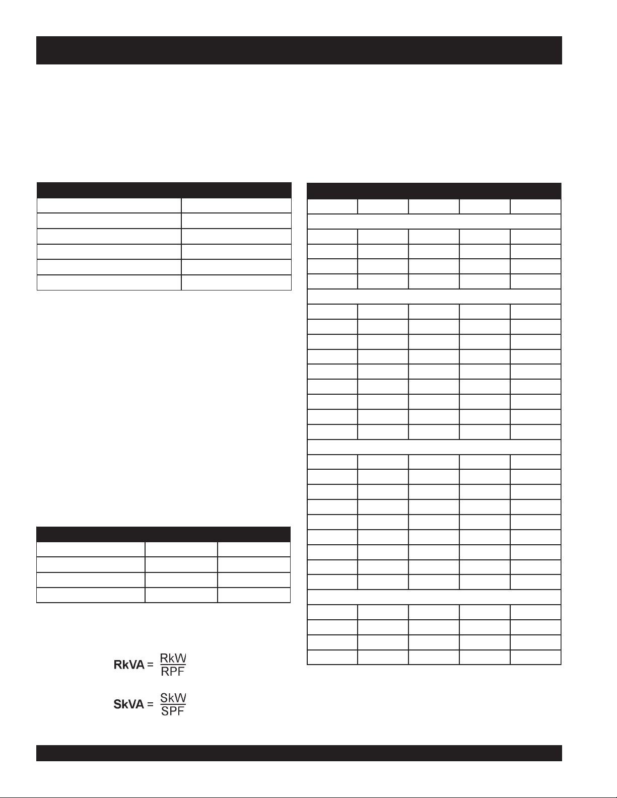
Typical ballast wattages are defined by Table 2 below:
segattaWtsallaB.2elbaT
PMALTSALLAB
taeherP,W04,21-Thcni84W01
tratSdipaR,W04,21-Thcni84W41
tnecseroulFW04tuptuOhgiHW52
W001,yrucreMW53-81
W004,yrucreMW56-52
For all types of lighting loads, except for high intensity
discharge (HID), use the following:
SkW = RkW
Due to the starting characteristics of HID lighting, assume
that
PHWkRAVkRAVkSWkS
6/13.05.05.38.2
4/14.06.08.48.3
3/15.07.06.55.4
2/17.09.07.71.6
6/13.05.06.20.2
4/14.06.03.36.2
3/15.07.09.31.3
2/17.09.03.552.4
4/30.152.11.77.5
12.16.15.96.7
2/1-16.10.252.414.11
22.27.2912.51
33.31.45.828.22
SkW = 0.75 x RkW
6/13.05.08.23.2
Unless otherwise known, assume the follo wing starting and
running power factors (SPF and RPF, respectively , see Table
3 below) for the following types of lighting:
rotcaFrewoPgninnuR&gnitratS.3elbaT
gnithgiLfoepyTFPSFPR
tnecseroulF59.059.0
tnecsednacnI00.100.1
egrahcsiDytisnetnIhgiH58.009.0
Then the following can be calculated:
4/14.06.08.30.3
3/15.07.06.39.2
2/17.09.09.57.4
4/30.152.10.84.6
12.16.16.017.21
2/1-16.10.20.617.21
22.27.22.120.71
33.31.48.135.52
6/13.05.00.18.0
4/14.06.05.12.1
3/15.07.00.26.1
2/17.09.00.34.2
scitsiretcarahCrotoMesahPelgniS.4elbaT
esahPtilpS
nuRnoitcudnI/tratSroticapaC
nuRroticapaC/tratSroticapaC
)CSP(roticapaCtilpStnenamreP
PAGE 22 — INDUSTRIAL GENERATOR SETS — APPLICATION & INSTALLATION MANUAL — REV. #4 (09/07/07)
Page 23
GENSET SIZING — DETERMINING LO AD CHARACTERISTICS
Three-Phase Induction Motors
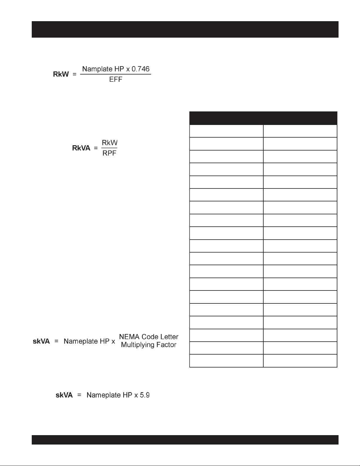
Calculate RkW as follows:
NEMA Code Letter Multiplying Factor
Use Table 5 below to calculate the starting kVA. DO NOT
confuse the NEMA (National Electrical Manufacturers
Association)
The code letter refers to the ratio of loc ked rotor kVA to HP,
whereas the design letter refers to the ratio of torque to speed.
If EFF (motor running efficiency) of the motor is not known,
refer to T ab le 5 and use the value corresponding to the motor
horsepower .
Calculate RkVA as follows:
If RPF (running power factor) is unknown, ref er to T a b le 5
and use the value corresponding to the motor horsepower .
Calculate SkVA as follows:
1. If the NEMA motor code letter is unknown, refer to
Table 4 on previous page and select the SkVA value
corresponding to the code letter and the horsepower.
The factors used to generate these values are shown
in T ab le 5.
motor code
A0.2
B3.3
C8.3
D2.4
E7.4
F3.5
G9.5
H7.6
J5.7
and
design letters
.
rotcaFgniylpitluMretteLedoCAMEN.5elbaT
2. If the NEMA motor code letter is unknown, refer to
Table 7 on page 25 and select the SkVA value in bold
letters that corresponds to the motor horsepower . The
bold letters show the values for the NEMA code letters
that are typical for standard motors.
3. If the motor is rated greater than 500 HP and the NEMA
motor code is known, calculate SkVA as follows:
4. If the motor is rated more than 500 HP and the NEMA
motor code is not known, assume a NEMA code letter
of G and calculate SkVA as follows:
where 5.9 is the multiplying factor corresponding to NEMA
code letter G in Table 5.
K5.8
L5.9
M6.01
N8.11
P2.31
R0.51
S0.61
T0.91
U2.12
V0.32
INDUSTRIAL GENERATOR SETS — APPLICATION & INSTALLATION MANUAL — REV. #4 (09/07/07) — PAGE 23
Page 24
GENSET SIZING — DETERMINING LO AD CHARACTERISTICS
Determining Load Characteristics (continued)
5. If reduced voltage motor starting is used, determine
SkVA as in Steps 1, 2, 3, or 4 on previous page, and
then multiply the value by the appropriate multiplying
factor in Table 5. Use the following formula:
lluF%
dohteMgnitratS
egatloVlluF0010010010.1—
egatloVdecudeR
remrofsnartotuA
rotcaeRseireS
rotsiseRseireS
egatloV
deilppA
08
56
05
08
56
05
08
56
05
46
24
52
08
56
05
08
56
05
Calculate SkW as follows:
1. If SPF (Starting Power F actor) is unknown, ref er to Table
4 on page 22 and use the value corresponding to the
motor horsepower.
motor starting is used, use the value for SPF
below .
2. Multiply SkW by 0.5 for motors with low inertia loads
(i.e., centrifugal fans, compressors and pumps) where
starting torque requirements are low.
lluF%
AVkegatloV
lluF%
egatloV
euqroT
46
24
52
46
24
52
46
24
52
If a resistor-type reduced voltage
in Table 6
scitsiretcarahCdnasdohteMgnitratSegatloVdecudeR.6elbaT
AVkS
gniylpitluM
rotcaF
46.0
24.0
52.0
08.0
56.0
05.0
08.0
56.0
05.0
FPS
—
—
—
—
—
—
06.0
07.0
08.0
atleDratS001333333.0—
)lacipyT(gnidniWtraP00106846.0—
rotoMrotoRdnuoW001*061*001*6.1—
ehtfoeulavehtnodnepedhcihw,tnerrucgninnurfosrotcafrostnecreperaesehT—*
.sgnidniwrotorehtotdeddasecnatsiserseires
PAGE 24 — INDUSTRIAL GENERATOR SETS — APPLICATION & INSTALLATION MANUAL — REV. #4 (09/07/07)
Page 25

GENSET SIZING — DETERMINING LO AD CHARACTERISTICS
Three Phase NEMA Motor Code Table
Table 7 lists the 3Ø motor star ting kVA, starting power factor, and motor factors. Do not confuse the NEMA (National
Electrical Manufacturers Association) motor Code and design letters. The code letter refers to the ratio of loc ked rotor kVA
to HP, whereas the design letter refers to the ratio of torque to speed.
FPRdna,FFE,FPS,AVkSrotoMesahPeerhT.7elbaT
PH
ABCDEFGHJKLNFPSFFEFPR
4/15.08.09.00.12.13.15.17.19.11.24.2
2/10.17.19.11.24.26.20.33.38.32.47.4
4/35.15.28.22.36.30.45.40.57.54.61.7
1 2 3 4 4 55678892167.00.3707.0
2/1-13566789011131
2478891121315171
36 0111314161810232
50151911242620333
2/1-751528223630454
0102338324743595
51030575461797
020476575859601
52054849601911231
0306001311721241951
0408431151071091212
05001761981212732562
06021102622552582813
57051152382813653793
001002533773524574035
521052814174135395266
051003205665736217497
0020049664579489499501
052005638349160168114231
00300640011311472142419851
05300717110231684116613581
00400883318051896189818112
005000137615881321237328462
sretteLedoCrotoMAMENsrotcaFrotoM
9.2
9.5
9.8
8127.09.6767.0
41
4207.01.9797.0
91
825366.05.2828.0
52
24749516.08.3858.0
83
7546179865.01.5878.0
05
57585981135.09.5878.0
76
00131172124177194.09.6888.0
98
43115107109163264.06.7898.0
911
76198121273259244.00.8898.0
941
10262255258245324.04.8898.0
871
86220304308357493.09.8809.0
832
53377352457409563.06.9809.0
792
20435401507580763.06.9809.0
753
20566573621758843.00.0909.0
644
076557948949081113.05.0919.0
595
73834926017811574192.09.0919.0
347
4001231147214241077182.02.1919.0
298
9331905199619981063252.07.1919.0
9811
4761688142124732059242.00.2919.0
6841
9002462294529482045322.03.2929.0
4871
3432146237923233031491.01.3929.0
1802
8762810389338973027491.01.3929.0
8732
8433377384248474009571.08.3929.0
3792
28.08.2655.0
28.08.2655.0
87.03.9646.0
INDUSTRIAL GENERATOR SETS — APPLICATION & INSTALLATION MANUAL — REV. #4 (09/07/07) — PAGE 25
Page 26
GENSET SIZING — DETERMINING LO AD CHARACTERISTICS
Synchronous Motors
Although starting requirements for synchronous motors are
lower , it is recommended to determine starting requirements
in the same manner as induction motors previously covered.
V ariable Frequency Drives
Variable Frequency Drives are nonlinear loads for which a
calculation of GkW is made, in addition to RkW , RkV A, SkW ,
and SkVA.
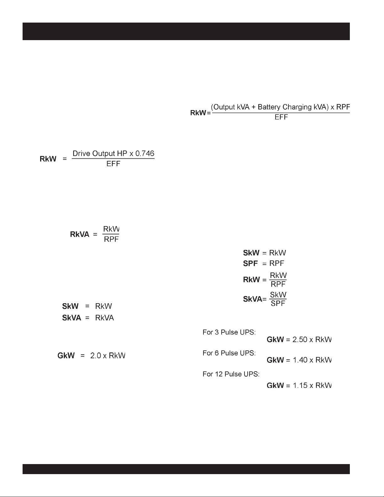
Calculate RkW as follows:
Assume 0.9 for EFF (drive running efficiency) unless
otherwise known.
Calculate RkVA as follows:
Static UPS
Uninterrupted power supplies are nonlinear loads for which
a calculation of GkW will be made, in addition to RkW , RkV A,
SkW, and SkVA.
Calculate RkW as follows:
In the equation above:
1. Output kVA is the nameplate kVA capacity of the
UPS
2. Battery charging kVA is that required for battery
charging, and can range from zero to fifty (0-50%)
percent of the UPS kVA rating.
3. If the RPF (Running Power Factor) for the UPS is
unknown, assume 0.9 RPF.
4. If the EFF (Running Efficiency) for the UPS is
unknown, assume 0.85 EFF.
Unless otherwise known:
Assume 0.9 for RPF (running power factor) unless
otherwise known.
Since these drives are all current limiting:
Calculate GkW as follows:
Calculate GkW using the following formula, assuming a
generator
When sizing for a pulse width modulated (PWM) drive,
consult the drive manufacturer to verify that the drive limits
harmonic current is less than 10 percent THD on a high
impedance source (e.g. a generator set), assume a sizing
factor of 1.4.
Using these factors for GkW results in selecting a generator
reactance low enough to limit voltage distortion caused by
nonlinear loads to approximately 10 to 15%.
sizing factor of 2
unless otherwise known.
T elecom DC Rectifiers and Battery Charging Equipment
Telecom DC Rectifiers and battery charging equipment are
nonlinear loads and similar to static UPS and should be
sized using the same method.
PAGE 26 — INDUSTRIAL GENERATOR SETS — APPLICATION & INSTALLATION MANUAL — REV. #4 (09/07/07)
Page 27
ENVIRONMENT AL CONSIDERATIONS — dB(A)
Noise Consideration
Because noise effects the surrounding environment, it is
important to consider noise factors when installing a genset.
The following is a brief approach to evaluating noise sources
and noise level reduction.
Noise requires a source, a path, and a receive r. In a standby
system, the genset is the source, the path is air or air and a
structure which transmits the noise vibrations, and the
receiver is a person in the vicinity (including the operator).
Since little prevention can be done with the source or the
receiver , the treatment method is to manipulate the pathwa y
of noise.
The three main components of noise from an enginegenerator set are:
1. Engine exhaust (low frequency sound)
2. Engine moving parts (low and high frequency sound)
3. Radiator discharge air (high frequency sound).
Noise Laws and Regulations
There are many state and local codes establishing maximum
noise levels. Most noise regulations specify the maximum
allowable noise level at the property line. Table 8 is an
example of typical maximum allowable noise levels. OSHA
has specific noise regulations where persons working in a
generator room will be required to wear ear protection.
Noise Level Measurement and Decibel / dB(A) Units
T o measure noise properly , the subjective response of human
hearing is substituted by an objective measurement of sound
measured by a meter. The unit of measurement for sound
is the decibel (dB). The decibel is a convenient number on
a logarithmic scale expressing the ratio of two sound
pressures, comparing the actual pressure to a reference
pressure.
Noise regulations are written in terms of "decibels 'A' scale"
or dB(A). This term means the sound pressure level has
been adjusted to duplicate how the imperfect human ear
hears noise. The human ear can only hear within a r ange of
frequencies. The dB(A) weighted scale tries to simulate
human loudness perception. Loudness is dependent on
sound pressure lev el (amplitude) and frequency . See Figure
2 on page 28 for a dB(A) comparison.
Decibel tests are conducted in a "free field". A free field is
a sound field in which the effects of obstacles or boundaries
on sound propagated in the field are negligible. A "reverberant
field" is a sound field in which the effects of obstacles or
boundaries on sound propagated in the field are not negligible.
Accurate noise measurements require the microphone to
be placed outside the "near field". The near field is defined
as the region within one wavelength or two times the largest
dimension of the noise source, whichev er is g reater. Noise
cannot be measure accurately for compliance with
specifications calling for measurements within the near field.
Noise measurements should be made using a sound level
meter and octave band analyz er. The microphones should
be placed in a circle of 23 feet (7 meters) radius centered on
the generator set.
sleveLesioNedistuOrofairetirClacipyT.8elbaT
senoZesioN
laitnediseR—nabrU26257574
laitnediseR—nabrubuS75742524
ronabrubuSetiuQyreV
laitnediseRlaruR
yrtsudnIybraeN—nabrU76752625
yrtsudnIyvaeH27267675
INDUSTRIAL GENERATOR SETS — APPLICATION & INSTALLATION MANUAL — REV. #4 (09/07/07) — PAGE 27
yaDkaeP
)A(Bd
25247473
thgiNkaeP
)A(Bd
suounitnoC
yaD
)A(Bd
suounitnoC
thgiN
)A(Bd
Page 28

ENVIRONMENT AL CONSIDERATIONS — dB(A)
Comparison Chart dB(A)
Figure 2 below provides a comparison of dB(A) levels for
daily noises and the typical range of generator sets. Open
generator sets are unhoused units where the path of noise
is unobstructed. An acoustic housing encloses the genset
to impede and absorb the path of noise.
For applications that require even quieter operation, see the
WhisperWatt™ product line f or dB(A) lev els as low as 62. If
quieter levels are required, please contact an MQ Power
dealer.
Figure 2. dB(A) Comparison Chart
PAGE 28 — INDUSTRIAL GENERATOR SETS — APPLICATION & INSTALLATION MANUAL — REV. #4 (09/07/07)
Page 29
ENVIRONMENT AL CONSIDERATIONS — dB(A)
Adding Additional Sound Sources
The noise level at a given location is the sum of the noise
levels from all sources, including reflecting sources. For
example, the noise level in a free field along side of two
identical generator sets would be double the noise level of
either set when both sets are running. A doubling of the
noise level is represented as an increase of approximately
3 dB(A). In this case, if the noise level from either set is
measured as 70 dB(A), the expected result of the combined
generators would be 73 dB(A) when both units are running.
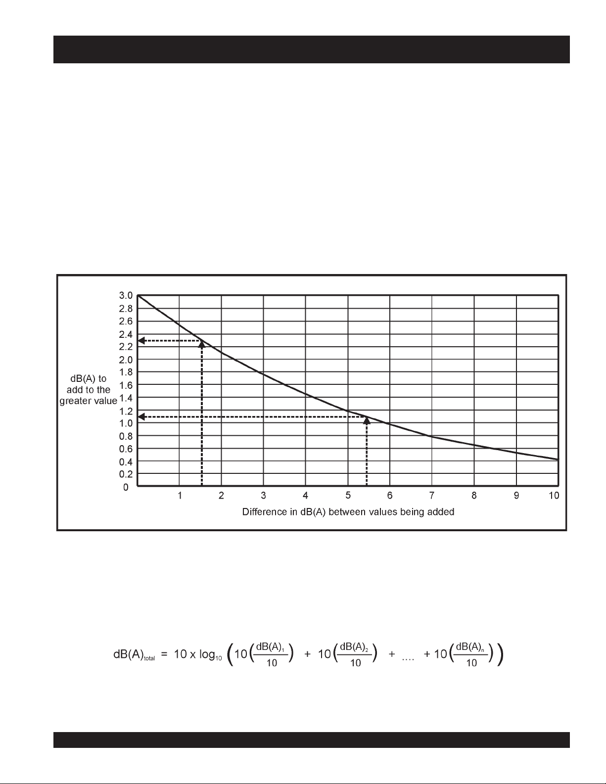
Figure 3 below estimates the noise level from multiple
noise sources:
1. To find the difference in dB(A) between two of the
sources (any pair), locate the dB(A) difference value
on the horizontal scale as shown by the horizontal arrow .
Add this value to the larger dB(A) value of the pair.
2. Repeat Step 1 between the value just determined and
the next value. Keep repeating the process until all
noise sources have been accounted for.
Figure 3. dB(A) Comparison Chart
Alternatively, the following formula can be used to add
sound pressure levels measured in dB(A):
INDUSTRIAL GENERATOR SETS — APPLICATION & INSTALLATION MANUAL — REV. #4 (09/07/07) — PAGE 29
Page 30

ENVIRONMENT AL CONSIDERATIONS — dB(A)
Effects of Distance
As the distance between a noise source and receiver
increases, the sound level decreases. If a second sound
measurement is taken twice as far from the source, the
second reading will be approximately 6 dB(A) less than the
first reading. If the sound pressure level (SPL
at distance d
distance d
is known, the sound pressure level (SPL
1
can be found as follows:
2
) of a source
1
2
It should be noted the background noise level must be at
least 10 dB(A) below the noise level of the generator set,
the installation must approximate a free field environment
and the generator set must be equipped with a critical grade
muffler.
) at
Figure 4. below can be used as an alternative to the formula
for estimating the sound level at various distances (such as
to the property line). For instance , as shown by the dashed
arrows, if the noise rating of the generator set is 95 dB(A) at
7 meters, the noise level 100 meters away will be
If the sound pressure level (SPL
dB(A), then at 7 meters (d
) the sound pressure level (SPL
2
) at 21 meters (d1) is 100
1
will be:
approximately 72 dB(A).
)
When using Figure 4, draw a line parallel to the slanted lines
2
from the known dB(A) value on the vertical scale line to the
vertical line for the specified distance. Then dra w a horizontal
line back to the ver tical scale line and read the new dB(A)
value.
Figure 4. Distance Effects on dB(A)
PAGE 30 — INDUSTRIAL GENERATOR SETS — APPLICATION & INSTALLATION MANUAL — REV. #4 (09/07/07)
Page 31

ENVIRONMENT AL CONSIDERATIONS — dB(A)
Reducing Noise
Structure-Borne Noise
Structure-borne noise is transmitted or generated as
vibrations in structures. Vibrating structures create sound
pressure wav es (noise) in the surrounding air . Connections
to a genset can cause vibrations in the building structure,
creating noise. Typically, these include the skid anchors,
radiator discharge air duct, exhaust piping, coolant piping,
fuel lines, and wiring conduit. Also, the walls of a genset
housing can vibrate and cause noise.
Reducing Noise
Airborne Noise
Airborne noise is usually the most dominant type of noise.
Airborne noise has a directional characteristic, particularly
at the high end of the frequency range. Table 9 below shows
ways of minimizing airborne noise.
The following will help reduce airborne noise:
1. Redirect noise away from receiv ers. V ertical radiator or
exhaust outlets point the noise away from people at
grade level and keep them out of the path of noise.
2. Line-of-sight barriers are effective in reducing noise. A
The following will help reduce structure-borne noise:
1. Mounting a genset on spring-type vibration isolators
effectively reduces vibration transmission. See the
Mounting section of this manual for details (page 33).
2. Flexible connections to exhaust pipe, fuel line, air duct,
coolant pipe (remote radiator or heat exchanger
systems), and wiring conduit effectively reduce vibration
transmission. Flexible connections are required when
the genset is mounted on vibration isolators.
3. See Figure 5 on page 32 for typical measures in reducing
noise.
sound barrier wall will reduce noise by blocking the sound
path of travel. Making noise travel through a 90 degree
bend in a duct reduces high frequency noise.
3. Cover enclosure walls, ceiling, and air duct with sound
absorbing (acoustic) material.
4. Remote radiators with low speed fans can be used both
to reduce the level of noise at the source and to isolate
it.
5. Critical grade mufflers are recommended whenever noise
control is a concern. The objectionable portion of engine
exhaust noise f alls within the range of 125 to 1,000 hertz.
Regardless of the grade of muffler selected, its effective
(peak) attenuation should be within this frequency range.
Typical noise attenuating ratings of mufflers are as
follows:
sgnitaRrelffuMdetaunettAesioN.9elbaT
relffuMlairtsudnI)A(Bd81-21
relffuMlaitnediseR)A(Bd52-81
relffuMlacitirC)A(Bd53-52
INDUSTRIAL GENERATOR SETS — APPLICATION & INSTALLATION MANUAL — REV. #4 (09/07/07) — PAGE 31
Page 32

ENVIRONMENTAL CONSIDERA TIONS — dB(A)
Acoustic Material
Consider the following when selecting acoustic material:
1. DO NOT use fiberglass as an acoustic material.
Acoustic Material
Figure 5 below illustrates installation methods for reducing
noise level to achieve a quieter operating generator set.
Fiberglass is a poor selection of acoustic material
because of its low density, poor flame retardant, and
poor cleanability.
2. Foam is least likely to deteriorate due to abrasion and
has good aesthetics. Howe ver , f oam is difficult to clean
and not all foams are fire retardant.
3. A concrete block enclosure is an excellent barrier in
regards to noise reduction. The blocks may be filled
with sand to make the wall more dense. However,
concrete housing tends to become hot and superior
cooling methods will be required for proper engine
performance.
Structure of
Sufficient Density
to Contain Noise
Vertical
Exhaust
Critical Grade
Muffler 25-35 dB(A)
Attenuation
Wind / Noise Barrier
Flexible Duct
Isolation
Foundation
Section
Vibration
Isolator
Figure 5. Reducing Noise
Flexible Exhaust
Connector
Acoustic
Louvers
PAGE 32 — INDUSTRIAL GENERATOR SETS — APPLICATION & INSTALLATION MANUAL — REV. #4 (09/07/07)
Page 33

MOUNTING FOUNDA TION
Mounting
Mounting the generator set is a critical part of the installation.
A proper foundation must be able to suppor t the weight of
the generator set and its accessories, resist dynamic loads,
and not transmit excessive noise and vibration. Foundations
can be located on the floor, roof, indoors, or outdoors.
Generator sets are typically mounted on a steel skid that
provides support. Vibration isolators are recommended
between the skid and the foundation to provide stable
operation and avoid installation damage. Bolting the
generator set directly to the floor or foundation can result in
excessive noise and vibration, and possible damage to the
genset and floor/foundation. See Vibration Isolators on page
36 for details.
Access to Set
Whenever choosing a generator site location, always allow
room for service personnel and operators to gain the proper
access to the unit. Always provide adequate lighting around
the unit.
Mounting on a Slab Floor
When mounting the genset on a concrete slab floor, a
concrete pad should be poured on top of the floor. The
concrete pad should be reinforced concrete with a 28 day
compressive strength of at least 2500 psi (173 kP a), howev er
3000 psi is recommended. It should be at least 6 inches
(150 mm) deep and extend at least 6 inches (150 mmm)
beyond the generator skid on all sides. Type J or L bolts
may be used to anchor the skid or vibration isolators to the
pad. Where allowed, drill-in anchors can be used.
Mounting on a Sub-Base Fuel Tank
When mounting the genset on a subbase fuel cell, the
vibration isolators may be installed between the genset and
the fuel tank. The fuel tank must be able to suppor t the
weight of the genset and resist the dynamic loads. It is
recommended that the tank be mounted with air space
between the bottom of the tank and the floor underneath to
reduce corrosion and permit visual inspections for leaks.
Mounting on a Vibration Isolating Foundation
When mounting the genset on a foundation to reduce the
transmission of vibrations to the building, the weight (W) of
the foundation should be at least 2 times the weight of the
genset itself to resist dynamic loading. Figure 6 on page 34
illustrates a typical vibration isolating foundation.
Consider the following when mounting on a vibration isolating
foundation:
The foundation should extend at least 6 inches beyond
the skid on all sides. This determines the length (L) and
width (w) of the foundation.
Calculate the height (h) of the foundation necessary to
obtain the required weight (W) by using the following
formula:
where d is the density of concrete, typically 145 lbs/ ft
(2322 kg/ m3)
For convenience in general servicing such as radiator,
fan belt, and oil filter maintenance, the surface of the
mounting base should be at least 6 inches (152 mm)
above the floor.
The foundation must extend below the frost line to
prevent heaving.
The foundation should be reinforced concrete with a 28
day compressiv e strength of at least 2500 psi (173 kPa),
however 3000 psi is recommended.
The total weight (TW) of the genset, fuel, and
foundation usually results in a soil bearing load (SBL) of
less than 2000 lbs / ft2 (96 kPa). Although this is within
the load bearing capacity of most soils, always find out
the allowable soil bearing load by checking the local
code and the soil analysis report of the building. The
soil bearing load can be calculated by using the
following formula:
3
Another method is to size the isolator to support the weight
of the engine-generator accessories, subbase fuel cell, and
fuel. Isolators should be mounted underneath the tank.
INDUSTRIAL GENERATOR SETS — APPLICATION & INSTALLATION MANUAL — REV. #4 (09/07/07) — PAGE 33
where "L" and "w" are the length and width of the foundation.
z
Type J or L bolts should be used to anchor the skid or
vibration isolators to the foundation.
Page 34

MOUNTING FOUND A TION
Mounting Foundation
Figure 6 below shows the typical foundation installation.
Figure 7 below shows the typical footing on a foundation in
soil with a low load bearing capacity.
Figure 6. Typical Foundation
Figure 7. Typical Footing
PAGE 34 — INDUSTRIAL GENERATOR SETS — APPLICATION & INSTALLATION MANUAL — REV. #4 (09/07/07)
Page 35

MOUNTING THE GENERATOR SET
General Information
Generator set installations must be engineered so the
generator set will function properly under the expected load
conditions. Use these instructions as a general guide only.
Follow the instructions of the consulting engineer when
locating or installing any components. The complete
installation must comply with all local, state, and federal
building codes, fire ordinances, and other applicable
regulations.
Always consider the following prior to installation:
z
Level mounting surface
z
Adequate cooling air
z
Adequate fresh induction air
z
Discharge of radiator hot air
z
Discharge of exhaust gases
z
Electrical connections
z
Accessibility for operation and servicing
z
Noise levels
z
Vibration isolation
Mounting
Mount the generator set on a substantial and level base
such as a concrete pad described previously in the
Foundation section. Provide properly sized mounting bolts
to secure the vibration isolators to the skid using flat or
bevel washers and hexagonal nuts for each bolt. (See Figure
8 below .)
The isolators should be located as shown on the genset
outline drawing.
Location
The generator set location is decided mainly by related
systems such as ventilation, wiring, fuel, and exhaust. The
set should be located as near as possible to the main power
distribution panel.
The generator set should be installed in a protected location
that is guarded against vandalism, theft, and unauthorized
tampering.
Always provide an optimal installation site that is away from
extreme ambient temperatures and that will provide
maximum protection against adverse weather conditions.
Incorrect installation or service can result in severe
personal injury or death, and/or equipment damage. Only
qualified service personnel should be allowed to perform
electrical and mechanical component installation.
NEVER install genset over combustible materials. Locate
genset such that combustible material can not accumulate
under the assembly. The possibility exists of fire or
explosion, causing damage to the equipment and or
severe bodily harm — even death!
Vibration Isolators
Steel spring isolators can provide up to 98% reduction in
the force of vibration transmission. Locate the vibration
isolator between the genset skid and foundation in
accordance with the installation drawing. The installation
may require 4, 6, 8, or 12 vibration isolators.
NOTE
Figure 8. Bolt Diagram
Always consult local air quality
authorities before completing your
construction plans. In most instances,
standby power units must be registered
with the local air pollution control district.
INDUSTRIAL GENERATOR SETS — APPLICATION & INSTALLATION MANUAL — REV. #4 (09/07/07) — PAGE 35
Page 36

MOUNTING — VIBRA TION ISOLA T ORS
Vibration Isolators
Installation and Adjustment Procedure
1. Place the vibration isolators on the genset support
structure. The isolators should be shimmed or grouted
to ensure that all of the isolator bases are within 0.25
inch (6 mm) elevation of each other. The surface the
isolator bases rest on must also be flat and level.
(See Figure 9 to the right.)
2. Loosen the snubber lock nuts so that the top plate of
the isolator is free to move v ertically and horizontally .
Be sure the top plate is correctly aligned with the
base and springs.
3. Place the genset onto the isolators while aligning the
skid's mounting with the threaded isolator hole. The
top plates will move down and approach the base of
the isolator as the weight of the generator is applied.
4. Once the genset is in position, the isolators may
require adjusting so that the set is lev el. The isolators
are adjusted by inserting the leveling bolt through
the skid and into the isolator (the leveling bolt's
locking nut should be threaded up towards the bolt
head). The leveling bolt will adjust the clearance
between the top plate and the isolator base. A
nominal clearance of 0.25 inch (6 mm) or greater is
desired. This will pro vide sufficient clearance f or the
rocking that occurs during start-up and shutdown. If
the 0.25 inch clearance is not present, turn the leveling
bolt until the desired clearance is achieved.
Figure 9. Vibration Isolator
Set mounted radiator-cooled generator sets:
Make sure radiator skid and engine/alternator skid are
level with each other after adjusting isolators. Improper
fan belt alignment may occur is the unit is not level.
5. Adjust the leveling bolts until the set is level and
sufficient clearance still remains. The clearance on
all isolators should be roughly equal. Once all isolators
have been set, lock the leveling bolt in place with
the lock nut.
6. The snubber nuts must remain loose to provide better
isolation between the genset and support structure.
Figure 10. Vibration Isolator Installation
PAGE 36 — INDUSTRIAL GENERATOR SETS — APPLICATION & INSTALLATION MANUAL — REV. #4 (09/07/07)
Page 37

MECHANICAL INST ALLA TION — FUEL SYSTEM (DIESEL)
MECHANICAL CONNECTIONS
Introduction
After considering all applicable codes and laws and finding
a suitable location site for the generator set, the installer
should consider the mechanical connections that will be
necessary to make during installation. The four (4) systems
that could require mechanical connections are the following:
z
Fuel system
z
Exhaust system
z
Ventilation system
z
Cooling system
Fuel System Installation
Proper installation of the fuel system is essential in obtaining
proper genset performance, safe working conditions, and
preventing property and environmental damage.
When planning an installation, check state and local codes
regarding fuel storage and handling. Piping and fuel system
components must conform to these regulations. Most
applications in the United States require that storage tanks,
day tanks, and subbase fuel tanks be UL listed. The UL
listing indicates that the tank has conformed to a series of
construction and testing standards. In addition, most tanks
must conform to National Fire Protection Association (NFPA)
construction and installation requirements. The three NFPA
codes that apply to day tanks and subbase fuel tanks are
NFP A 30, Flammab le and Combustible Liquids Code; NFP A
37, Standard for Installation and Use of Stationary
Combustible Engine and Gas Turbines; and NFPA 110,
Standard for Emergency and Standby Power Systems.
Use only compatible metal fuel lines to avoid electrolysis.
This practice is particulary important when fuel lines must
be buried. Buried fuel lines must be protected from any
kind of corrosion. Use a
flexible
section of tubing between
the engine and fuel supply line to prevent vibration damage.
Refer to the generator set manual for outline drawings and
detailed information.
NEVER use galvanized or copper fuel lines and fittings for fuel
tank connection. Condensation in the tank and fuel lines
combines with the sulfur in diesel fuel to produce sulfuric acid.
The molecular structure of the copper or galvanized lines reacts
with the acid and contaminates the fuel, which can clog filters
and damage the engine fuel injection pump.
Diesel Fuel
MQ Po wer Industrial generator sets use ASTM No. 2 Diesel
fuel. If an alternate diesel fuel is required, consult the
appropriate engine manual.
The main components of a typical diesel fuel system are
the fuel storage tank, fuel lines, transfer fuel tanks or day
tanks, and auxiliary fuel pumps or lift pumps. Fuel storage
tanks may be located indoors or outdoors, providing they
meet local code requirements. The fuel supply tank should
be located near the diesel engine to enable the engine
mounted fuel transfer pump to operate within its capability.
Fuel filters and fuel/water or sediment separators must be
easily accessible for regular and scheduled maintenance. It
is important to have a clean installation, making ev ery effort
to prev ent entrance of moisture, dirt or contaminants of any
kind. Clean all fuel system components before installing.
Supply Tank
Locate the supply fuel tank as close as possible to the
generator set and within the five (5') foot (1.5 m) lift capacity
of the engine fuel pump. Any fuel tank transfer pump capacity
and supply piping should be sized on the basis of the
maximum fuel flow rating. Refer to the generator set data
sheet for detailed fuel consumption data.
If the main fuel tank is installed below the lift capabilities of
the standard engine fuel pump, a transfer tank (referred to
as a day tank) and auxiliary pump also will be required. If
an overhead main fuel tank is installed, a transfer tank and
float valve will be required to prevent fuel head pressures
from being placed on the fuel system components.
Fuel leaks create fire and explosion
hazards which can result in severe
personal injury or
flexible tubing between the engine and
fuel supply to avoid line failure and
leaks due to vibration. The fuel system
must meet applicable codes.
death!
Always use
INDUSTRIAL GENERATOR SETS — APPLICATION & INSTALLATION MANUAL — REV. #4 (09/07/07) — PAGE 37
Page 38

MECHANICAL INST ALLATION — FUEL SYSTEM (DIESEL)
Subbase T ank
Base mounted or subbase fuel tanks are used to store
fuel directly underneath the engine-generator set,
eliminating the need for a remote main fuel supply tank
and/or auxiliary fuel transfer pumps. This mounting
arrangement offers the convenience of having a fuel supply
tank mounted at the generator .
These tanks are designed to be contained in a rectangular
base on which the engine-generator set is mounted.
Generally, these tanks only increase the height of the
generator set since the tank base is usually matched to
the generator skid dimension. For many installations, this
type of tank offers advantages over above ground and
below ground tanks due to stringent environmental laws
making it difficult or impossible to gain necessary
approvals.
Subbase fuel tanks are available with the UL142 listing
under the special purpose tank category of NFP A. These
tanks are availab le in various capacities and designs. When
a subbase fuel tank is used, the tank should be designed
with a stub-up area on the generator-end of the tank.
This feature allows for an open area on the tank assembly
whereby electrical terminations can be brought up
underneath the engine-generator for final termination (refer
to Electrical Connections section).
Using oversized subbase fuel tanks, where the tank is larger
than the skid of the generator, can cause difficulty in
completing final electrical connections. The tank should be
designed with a stub-up area on the generator-end of the
tank. However, depending on the placement of the enginegenerator on the tank, feeder terminations may not rise in a
close proximity to the circuit breaker. This could require the
feeder conductors to enter the circuit breaker enclosure from
the side or top, necessitating special fittings and/or hardware.
Be sure to check with the local inspection authority before
proceeding.
Failure to pro vide an overflo w line to the
supply tank from the day tank can cause
spilled fuel, safety hazards, and damage
to equipment. Wipe up any spilled fuel
immediately. Spilled fuel if ignited can
cause a fire or explosion, causing
damage to the equipment and severe
bodily harm — even
death!
Day T ank
Fuel day tanks are used when the engine fuel pump does
not have the capacity to draw the fuel from the supply tank;
or the supply tank is overhead and presents problems of
high fuel head pressure for the system.
In high ambient conditions, the day tank temperature might
need to be considered. W arm fuel returning from the engine
fuel injection pump should not be returned to the day tank if
possible. As fuel temperature increases, fuel density and
lubricity decrease, reducing maximum power output and
lubrication of fuel handling parts such as pumps and injectors.
may
This
tank rather than the day tank.
Supply Tank Lower than Engine Installation
If a supply tank is lower than the engine, the day tank is
installed near the generator set and within the engine
fuel pump lift capability, but below the fuel injection
system. Install an auxiliary fuel pump as close as
possible to the supply tank to pump fuel from the supply
tank to the day tank. A float switch in the day tank
controls operation of the auxiliary fuel pump.
The supply tank top must be below the day tank top to
prevent siphoning from the fuel supply to the day tank.
Provide a return line from the engine injection system
return connection to the day tank (near the top). Provide
a day tank overflow line to supply tank in case the float
switch fails to shut off the fuel transfer pump.
Supply Tank Higher than Engine Installation
If a supply tank is higher than the engine, the day tank is
installed near the generator set, but below the fuel
injection system. Fuel lines should at least be as large
as the fuel pump inlet. The engine fuel return line must
enter the day tank.
Include a shut-off valve in the fuel line between the fuel
supply tank and the day tank to stop fuel flow when the
generator set is not in use and the battery is disconnected
(Off Mode).
Engine Fuel Connections
Identification tags are attached to the fuel supply line
and fuel return line connections by the factory. Flexible
lines for connecting between the engine and stationary
fuel line are supplied as standard equipment.
be avoided by returning the fuel back to the supply
PAGE 38 — INDUSTRIAL GENERATOR SETS — APPLICATION & INSTALLATION MANUAL — REV. #4 (09/07/07)
Page 39

MECHANICAL INST ALLATION — FUEL SYSTEM (DIESEL)
Diesel Fuel Supply
Consider the following when installing a diesel fuel supply
system:
Fuel supply tank construction, location, installation,
venting, piping, testing, and inspection must comply with
all applicable codes. In addition, see NFPA Standards
No. 30 and No. 37.
Fuel supply tanks must be adequately vented to prevent
pressurization, have provisions for manually draining or
pumping out water and sediment, and have at least a
five percent expansion space to prevent fuel spillage
when the fuel heats up and expands.
The fuel lift pump, day tank transfer pump, or float valve
seat should be protected from fuel supply tank debris by
a pre-filter or sediment bowl with a 100 to 120 mesh
element.
The supply tank must hold enough fuel to run the genset
for the prescribed number of hours (NFPA No. 110 Class
designation) without refueling. Tank sizing calculation
should be based on the hourly fuel consumption rates
on the genset specification sheet.
For emergency power systems, codes might not permit
the fuel supply to be used for any other purpose, or may
specify a drawdown level for other equipment that
guarantees the fuel supply for emergency power use.
The cetane rating of No. 2 heating oil is not high enough
for dependable starting of diesel engines in extreme cold
weather climates. Therefore , separate supply fuel tanks
for emergency power and building heating systems may
have to be provided.
Approved flexible fuel hose must be used for connections
at the engine to prevent damage from genset movement
and vibration.
Diesel fuel lines should be black iron pipe. Cast iron and
aluminum pipe and fittings must NOT be used because
they are porous and can leak.
Galvanized fuel lines, fittings, and tanks SHOULD NOT
be used because the galvanized coating reacts with the
sulfuric acid that forms when the sulfur in the fuel
combines with tank condensation. Such a practice would
result in debris that can clog fuel pumps and filters.
Although copper has been used for diesel fuel lines in
the past, black iron pipe is preferred. Diesel fuel
polymerizes (thickens) in copper tubing during long
periods of standby. This can cause the fuel injectors to
clog.
Refer to the engine specification sheet for the maximum
fuel inlet and return restrictions, the maximum fuel flow,
and the fuel consumption. Then refer to Table 10 for the
minimum hose and pipe sizes for connections to a supply
tank or day tank that is relatively close to the set at
approximately the same elevation. Hose and pipe size
should be based on the maximum fuel flow rather than
the fuel consumption
twice the full-load fuel consumption)
recommended that the fuel inlet and return restrictions
be checked before the set is placed into service.
Separate fuel return lines to the day tank or supply tank
must be provided for each generator set in a multiple-set
installation to prevent the return lines of any idle set from
being pressurized. Also, a fuel return line must NOT
include a shut-off device. Engine damage will occur if
the engine is run when the fuel line is shut off.
A day tank is required whenever pipe friction and/or supply
tank elevation, either below the fuel pump inlet or above
the fuel injectors, would cause an excessive fuel inlet or
return restriction.
For critical start applications, where gensets are paralleled
or must satisfy emergency start-time requirements, it is
recommended that a fuel tank or reservoir be located
such that the lowest possible fuel level is not less than 6
inches (150 mm) above the fuel pump inlet. This will
prevent air from accumulating in the fuel line while the
genset is in standby, eliminating the period during startup when the air has to be purged.
mumixaM
HPG
wolFleuF
51-06.oN
02-618.oN
08-1201.oN
001-1821.oN
061-10161.oN
<06161.oN
(The maximum fuel flow can be
. It is highly
seziSepiPdnaesoHnruteR/ylppuSleuFmuminiM.01elbaT
eniLylppuSleuFeniLnruteRleuF
teeF01-0
)serteM3-0(
xelF
esoH
eziS
.D.IepiP
sehcnI
)mm(
61/5
)9.7(
23/31
)3.01(
2/1
)7.21(
8/5
)9.51(
8/7
)3.22(
8/7
)3.22(
teeF05-01
)serteM51-3(
xelF
esoH
eziS
8.oN
01.oN
21.oN
61.oN
61.oN
61.oN
.D.IepiP
sehcnI
)mm(
23/31
)3.01(
2/1
)7.21(
8/5
)9.51(
8/7
)3.22(
8/7
)3.22(
8/7
)3.22(
teeF01-0
)serteM3-0(
xelF
esoH
eziS
4.oN
4.oN
8.oN
8.oN
01.oN
21.oN
.D.IepiP
sehcnI
)mm(
61/3
)8.4(
61/3
)8.4(
23/31
)3.01(
23/31
)3.01(
2/1
)7.21(
8/5
)9.51(
teeF05-01
)serteM51-3(
xelF
esoH
eziS
6.oN
6.oN
01.oN
01.oN
21.oN
21.oN
thgiehtfilleuflaminimdna,sgnittif°09owt,sgnittifthgiartsruofnodesaB
.D.IepiP
sehcnI
)mm(
61/5
)9.7(
61/5
)9.7(
2/1
)7.21(
2/1
)7.21(
8/5
)9.51(
8/5
)9.51(
INDUSTRIAL GENERATOR SETS — APPLICATION & INSTALLATION MANUAL — REV. #4 (09/07/07) — PAGE 39
Page 40

MECHANICAL INST ALLA TION — FUEL SYSTEM (GASEOUS FUELS)
Gaseous Fuels
Some MQ Power Industrial generator sets may utilize
gaseous fuels such as Pipeline natural gas or Liquid
Petroleum Gas (LPG). Regardless of the fuel used, the
primary factors in successful installation and operation of a
gas fuel system are:
The gas supplied to the generator set must be of
acceptable quality.
The gas supply pressure must be measured to ensure
that the gas supply at the generator set, not just at the
source, is of proper pressure must be available while the
generator is running at full load.
The gas must be supplied to the genset in sufficient
BTU Content
The total BTU content of the fuel will determine the rating of
the generator set when using fuel of a specific compostion.
If any component of the fuel has more than the specific
value allowed, der ating will be required. Consult MQ P ower
for fuel derating instructions.
TABLE 11. TYPICAL BTU CONTENT OF GASEOUS FUEL
DRY PIPELINE GAS FIELD GAS LPG
LHV HHV LHV HHV LHV HHV
936
3
BTU/ft
volume to support proper operation.
Pipeline Natural Gas
The most common gaseous fuel for generator sets is
Failure to meet the minimum requirements in these areas will
result in the inability of the generator set to operate or carry
rated load and will induce poor performance.
pipeline natural gas" has specific qualities based on
federal requirements. U.S. pipeline gas is a mixture
composed of approximately 98% methane and ethane
called
Pipeline natural gas
with the other 2% being hydrocarbons such as propane
Gaseous fuels are actually a mixture of several different
hydrocarbon gases and various contaminants, some of
which are potentially damaging to an engine over time.
and butane, nitrogen, carbon dioxide, and water vapor.
"Dry" means that is free of liquid hydrocarbons such as
gasoline, but NOT that it is free of water vapor.
The quality of the fuel is based on the amount of energy
per unit volume in the fuel and the amount of contaminants
in the fuel. Most gaseous fuel suppliers can provide a
fuel analysis that describes the chemical makeup of the
fuel that is to be provide to insure that the fuel is usable
for a specific application, and also to verify that the BTU
content of the fuel is sufficient to provide necessary kW
output of the genset.
Field Gas
The composition of
by region and continent. Careful analysis is necessary
prior to using field natural gas in an engine because in
can contain heavier hydrocarbon gases which may require
derating of the output of the engine. Field natural gas
may also contain other contaminants such as sulfur.
1,038
BTU/ft
1,203
3
BTU/ft
1,325
3
BTU/ft
. In the United States, "dry
Field natural gas
2,353
3
BTU/ft
2,557
3
BTU/ft
3
varies considerably
Energy Content
One of the most important characteristics of gaseous
fuel used in a generator set is the heat value of the fuel.
The value of a fuel describes how much energy is stored
in a specific volume of the fuel. Gaseous fuel has a low
heat value (LHV) and a high heat value (HHV). The low
heat value is the heat available to do work in an engine
after the water in the fuel is vaporized. If the low heat
value of the fuel is too low (generally below 905 BTU/ft
the engine will not be able to maintain full output power
Liquid Petroleum Gas (LPG)
Liquid Petroleum Gas is available in two grades,
commercial and special duty. Commercial propane is
used where high volatility is required. Special duty
propane (also called HD5) is a mixture of 95% propane
and other gases such as butane that allows better engine
performance due to the reduction pre-ignition due to
3
reduced volatility. Special duty propane fuel should meet
)
the ASTM D 1835 specifications for special duty propane.
and may not produce rated power at standard ambient
temperature conditions.
PAGE 40 — INDUSTRIAL GENERATOR SETS — APPLICATION & INSTALLATION MANUAL — REV. #4 (09/07/07)
Page 41

MECHANICAL INST ALLA TION — FUEL SYSTEM (GASEOUS FUELS)
Contaminants
The most harmful contaminants in gaseous fuels are water
vapor and sulfur. Water vapor is damaging to an engine
because it may cause uncontrolled burning, pre-ignition,
or other effects that can damage an engine. Liquid vapor
or droplets must be removed from the fuel prior to entry
into the engine by use of a dry filter that is mounted in
the fuel system prior to the primary fuel pressure regulator.
Sulfur and hydrogen sulfides will cause corrosion and
serious damage to an engine over a relative short periods
of time. The effects of sulfur in the fuel can be
counteracted in part by use of high-ash natural lubricating
oils. In general, engines should not be operated with fuels
in excess of 10 parts per million (ppm).
Gaseous Fuel Supply
Consider the following when installing a natural gas or LPG
fuel system:
Gaseous fuel supply system design, materials,
components, fabrication, assembly, installation, testing
inspection operation and maintenance must comply with
all applicable codes and standards. In addition, see NFP A
Standards No. 30, No. 37, No. 54 and No . 58.
The layout and sizing of gas piping must be adequate for
handling the volume of gas required by the genset and
all other equipment, such as building heating boilers
supplied by the same source. Full load gas flow must be
available at not less that the minimum required supply
pressure, typically from 5 to 10 inches WC (water column)
depending on the model. Final determination of pipe sizes
must however be based upon the method approved by
the authority having jurisdiction (see NFPA No. 54).
Most installations will require one or more service gas
pressure regulators. Gas supply pressure should not
exceed 13.8 or 20 inches WC at the inlet to the generator
set depending on the model. High pressure gas piping is
not permitted inside buildings (5 psig for natural gas and
20 psig for LPG unless higher pressures are approved
by the authority having jurisdiction). Gas pressure
regulators must be vented to the outdoors according to
code.
All fuel gas systems at service pressures of 125 psig
and less shall be installed in accordance with NFPA 54.
All fuel gas systems at service pressures in excess of
125 psig shall be installed in accordance with ANSI/
ASME B31.3.
LP-Gas systems, whether liquid or vapor phase, shall
be installed in accordance with the provisions of NFPA
58.
The pressure regulator installed on the supply line at the
gas source for generator applications should never be a
“pilot” regulator . A “pilot” style regulator is the type where
the regulator requires a pressure line from the regulator
housing to the downstream gas pipe to “sense” when
downstream pressure has dropped. Pilot regulators do
not work because the response time is unacceptable
compared to the large–instantaneous changes in demand
from the generator set.
Approved flexible fuel hose must be used for connections
at the engine to take up generator set movement and
vibration.
Most codes require both manual and electric (battery–
powered) shut-off valves ahead of the flexible fuel hose(s).
The manual valve should be of the indicating type.
A dry fuel filter should be installed in each line to protect
the sensitive pressure regulating components and orifices
downstream from harmful foreign substances carried
along in the gas stream (rust, scale, etc.).
The rate of vaporization in an LPG tank depends upon
the outdoor air temperature, unless the tank is equipped
with a heater, and the quantity of fuel in the tank. Even
on cold days ambient air heats and vaporizes LPG
(mostly through the wetted tank surface) when air
temperature is higher than LPG temperature. Withdr awing
vapor causes tank temperature and pressure to drop. (At
–37° F [–38° C] LPG has zero vapor pressure.) Unless
there is enough fuel and enough heat available from
ambient air, the vaporization rate will drop off, as the
generator set runs, to less than that required to continue
running properly .
Leakage of gaseous fuel is extremely dangerous. Natural gas
and LPG contain carbon monoxide which can cause severe
bodily harm or
and fires will occur if gas or propane leakage occurs where
there is a spark. To prevent such hazards, immediately shut off
all natural gas or propane supplies if a leak is detected. If in an
enclosed area, ventilate the area as quickly as possible.
death when inhaled. Also, serious explosions
INDUSTRIAL GENERATOR SETS — APPLICATION & INSTALLATION MANUAL — REV. #4 (09/07/07) — PAGE 41
Page 42

MECHANICAL INST ALLA TION — FUEL SYSTEM (GASEOUS FUELS)
Pipe and Tube Sizing
Sizing gas piping for proper fuel delivery , both f or flow and pressure is very important. T ables 12 thru 16 show maximum gas capacity
for equivalent length for various pipe sizes considering the general fuel sysem operating requirements for proper operation of the
generator set. The illustrations (Figures 11 thru 13) are typical pipe configurations for proper natural gas, liquid propane and
propane vapor distribution. Consult NFP A 54 or other applicable codes f or other operating conditions or other fuel system installation
requirements.
Figure 11. Typical Pipe Schematic for Natural Gas Distribution
TABLE 12. NATURAL GAS SCHEDULE 40 IRON PIPE SIZING
Pipe Size (in.)
1/4
3/8
1/2
Length
(0.364)
(ft.)
10 43 95 175 360 680 1400 2100 3950 6300 11000 23000
20 29 65 120 250 465 950 1460 2750 4350 7700 15800
30 24 52 97 200 375 770 1180 2200 3520 6250 12800
40
50
60 16 36 66 138 260 530 810 1520 2400 4300 8800
70
80
90 13 29 53 110 205 430 650 1220 1950 3450 7200
100 12 27 50 103 195 400 620 1150 1850 3250 6700
125 11 24 44 93 175 360 550 1020 1650 2950 6000
150
175
200
(0.493)
20 45 82 170 320 660 990 1900 3000 5300 10900
18 40 73 151 285 580 900 1680 2650 4750 9700
15 33 61 125 240 490 750 1400 2250 3900 8100
14 31 57 118 220 460 690 1300 2050 3700 7500
10 22 40 84 160 325 500 950 1500 2650 5500
9 20 37 77 145 300 460 850 1370 2450 5000
8 19 35 72 135 280 430 800 1280 2280 4600
3/4
(0.622)
(0.824)1(1.049)
Maximum Capacity in Cubic Feet of Gas per Hour
1 1/4
(1.380)
1 1/2
(1.610)2(2.067)
2 1/2
(2.469)3(3.068)4(4.026)
TABLE 13. NAT URAL GAS SEMI-R IGID COPPER TUB ING SIZING
1/4 3/8 1/2 5/8 3/4 1 1 1/4 1 1/2 2 2 1/2
Tube Size
* Table capacities are based on Type K copper tubing inside diameter (shown), which has the smallest inside
diameter of the copper tubing products.
K&L
(in.)
Outside
Inside *
Length (ft)
10
20
30
40
50 11 23 47 82 116 247 445 701 1461 2584
60
70
80
90
100
125 6.8 14 28 50 70 151 271 427 890 1574
150
175
200 5.2 11 22 39 55 117 210 331 690 1221
250
300
3/8 1/2 5/8 3/4 7/8 1 1/8 1 3/8 1 5/8 2 1/8 2 5/8
ACR
0.375 0.500 0.625 0.750 0.875 1.125 1.375 1.625 2.125 2.625
0.305 0.402 0.527 0.652 0.745 0.995 1.245 1.481 1.959 2.435
Maximum Capacity in Cubic Feet of Gas per Hour
27 55 111 195 276 590 1062 1675 3489 6173
18 38 77 134 190 406 730 1151 2398 4242
15 30 61 107 152 326 586 925 1926 3407
13 26 53 92 131 279 502 791 1648 2916
10 21 42 74 105 224 403 635 1323 2341
9.3 19 39 68 96 206 371 585 1218 2154
8.6 18 36 63 90 192 345 544 1133 2004
8.1 17 34 59 84 180 324 510 1063 1880
7.6 16 32 56 79 170 306 482 1004 1776
6.1 13 26 45 64 136 245 387 806 1426
5.6 12 24 41 59 125 226 356 742 1312
4.7 10 20 34 48 103 186 294 612 1082
4.2 8.7 18 31 44 94 169 266 554 980
PAGE 42 — INDUSTRIAL GENERATOR SETS — APPLICATION & INSTALLATION MANUAL — REV. #4 (09/07/07)
Page 43

MECHANICAL INST ALLA TION — FUEL SYSTEM (GASEOUS FUELS)
Figure 12. Typical Pipe Schematic for Propane Vapor Distribution
TABLE 14. PROPANE VAPOR SCHEDULE 40 IRON PIPE SIZING
Pipe Size (in.)
1/2
Length
(ft.)
10
20
30
40
50
60 110 231 434 892 1337 2574 7253 10619 14793
80
100
125
150 67 140 265 543 814 1568 4418 6468 9011
200
250
300
350
400
3/4
(0.622)
(0.824)1(1.049)
Maximum capacity in thousands of BTU per hour
291 608 1145 2352 3523 6786 19119 27993 38997
200 418 787 1616 2422 4664 13141 19240 26802
160 336 632 1298 1945 3745 10552 15450 21523
137 287 541 1111 1664 3205 9031 13223 18421
122 255 480 984 1475 2841 8004 11720 16326
94 197 372 763 1144 2203 6207 9088 12661
84 175 330 677 1014 1952 5501 8055 11221
74 155 292 600 899 1730 4876 7139 9945
58 120 227 465 697 1342 3781 5536 7712
51 107 201 412 618 1189 3351 4906 6835
46 97 182 373 560 1078 3036 4446 6193
42 89 167 344 515 991 2793 4090 5698
40 83 156 320 479 922 2599 3805 5301
1 1/4
1 1/2
(1.38)
(1.61)2(2.067)3(3.068)
3 1/2
(3.548)4(4.026)
TABLE 15. PROPANE VAPOR SEMI-RIGID COPPER TUBING SIZING
1/4 3/8 1/2 5/8 3/4 1 1 1/4 1 1/2 2 2 1/2
Tub e S i z e
* Table capacities are based on Type K copper tubing inside diameter (shown), which has the smallest inside
diameter of the copper tubing products.
K&L
(in.)
Outside
Inside *
Length (ft)
10
20
30
40
50 19 39 79 138 195 417 752 1185 2468 4366
60
70
80 15 30 61 107 152 324 583 919 1914 3386
90
100
125 11 24 48 84 119 254 458 722 1503 2660
150
175
200 8.9 18 37 65 92 197 355 560 1166 2062
225
250
275 7.5 15 31 55 78 166 299 471 981 1736
300
3/8 1/2 5/8 3/4 7/8 1 1/8 1 3/8 1 5/8 2 1/8 2 5/8
ACR
0.375 0.500 0.625 0.750 0.875 1.125 1.375 1.625 2.125 2.625
0.305 0.402 0.527 0.652 0.745 0.995 1.245 1.481 1.959 2.435
Maximum Capa city in Cu bic Feet of Ga s per Hour
45 93 188 329 467 997 1795 2830 5895 10429
31 64 129 226 321 685 1234 1945 4051 7168
25 51 104 182 258 550 991 1562 3253 5756
21 44 89 155 220 471 848 1337 2784 4926
17 35 71 125 177 378 681 1074 2236 3956
16 32 66 115 163 348 626 988 2057 3639
14 28 57 100 142 304 546 862 1796 3177
13 27 54 95 134 287 517 814 1696 3001
10 21 44 76 108 230 415 654 1362 2410
10 20 40 70 99 212 382 602 1253 2217
8.3 17 35 61 87 185 333 525 1094 1935
7.9 16 33 58 82 175 315 496 1033 1828
7.1 15 30 52 74 158 285 449 936 1656
INDUSTRIAL GENERATOR SETS — APPLICATION & INSTALLATION MANUAL — REV. #4 (09/07/07) — PAGE 43
Page 44

MECHANICAL INST ALLA TION — FUEL SYSTEM
Figure 13. Typical Pipe Schematic for Propane Liquid Distribution
TABLE 16. LIQUID PROPANE SCHEDULE 40 IRON PIPE SIZ ING
Length of
Pipe, ft.
2000
1/2
3/4
(0.622)
(0.824)1(1.049)
733 1532 2885 5924 8876 17094 48164 70519 98238
30
627 1311 2469 5070 7597 14630 41222 60355 84079
40
50 556 1162 2189 4494 6733 12966 36534 53492 74518
60 504 1053 1983 4072 6100 11748 33103 48467 67519
70 463 969 1824 3746 5612 10808 30454 44589 62116
431 901 1697 3484 5221 10055 28331 41482 57787
80
404 845 1593 3269 4899 9434 26583 38921 54220
90
382 798 1504 3088 4627 8912 25110 36764 51216
100
307 641 1208 2480 3716 7156 20164 29523 41128
150
262 549 1034 2122 3180 6125 17258 25268 35200
200
233 486 916 1881 2819 5428 15295 22395 31198
250
300 211 441 830 1705 2554 4919 13859 20291 28267
350 194 405 764 1568 2349 4525 12750 18667 26006
180 377 711 1459 2186 4209 11861 17366 24193
400
169 354 667 1369 2051 3950 11129 16295 22700
450
160 334 630 1293 1937 3731 10512 15391 21442
500
145 303 571 1172 1755 3380 9525 13946 19428
600
133 279 525 1078 1615 3110 8763 12830 17873
700
124 259 488 1003 1502 2893 8152 11936 16628
800
116 243 458 941 1409 2715 7649 11199 15601
900
110 230 433 889 1331 2564 7225 10579 14737
1000
1500
88 184 348 713 1069 2059 5802 8495 11834
76 158 297 611 915 1762 4966 7271 10128
Pipe Size, in.
1 1/4
1 1/2
(1.38)
(1.61)2(2.067)3(3.068)
3 1/2
(3.548)4(4.026)
Please observe the following when servicing natural gas
or LPG supply lines:
• Open any valve SLOWLY.
• DO NOT remove plugs or caps on connections if
shut off valves leak.
• Make sure all unloading connections are tight.
• DO NOT tamper with relief valves.
• NEVER place your face or any other part of your
body over safety relief valves.
PAGE 44 — INDUSTRIAL GENERATOR SETS — APPLICATION & INSTALLATION MANUAL — REV. #4 (09/07/07)
Page 45

MECHANICAL INST ALLA TION — FUEL SYSTEM
Fuel Storage Regulations
Use extreme care when using, transporting, and storing
fuel. Every measure should be taken to protect personnel
and the environment from the dangers of fuel. Fuel supply
tank design and installation in North America is controlled
by regulations that are generally written for fire protection
and environmental protection. It is very important to adopt
safe methods of storing fuel and to meet all applicable
codes and laws.
Even when an installation is exempt from regulation, it
should be recognized that cleanup expenses may be very
costly for even small amounts of fuel spillage from leaks,
overfilling, etc. The trend in diesel fuel storage for onsite gensets, both indoors and outdoors, has been towards
Underwriter Laboratories Listed above ground dual-wall
subbase tanks with leak detection.
Fuel leaks and spills can cause environmental
contamination. Make sure the area surrounding the fuel
tanks and lines will prevent fuel from entering soil, sewers,
and water .
Envir onmental Protection
Environmental protection regulations exist at both federal
and state levels. Different sets of regulations apply to
underground versus above-ground fuel storage tanks.
These regulations cover design and construction
standards, registration, tank testing, leak detection,
closure requirements, preparation of spill prevention plans
and provisions for financial responsibility and trust fund
coverage.
OSHA Standards for Flammable and Combustible Liquids,
exempts above ground installations made in accordance
with NFPA 37. Exemption status from state regulation
must be verified before installation.
Fire Protection
Fire protection regulations adopt by reference one or more
of the National Fire Protection Association (NFPA)
standards. These standards cov er the maximum amount
of fuel that can be stored inside buildings, fuel piping
systems, the design and construction of fuel tanks, fuel
tank locations, drainage provisions, etc. Local fire
marshals may have more restrictive requirements or
interpretations of requirements than national standards.
Additional references include:
z
UL 142, Steel Abo ve-ground Tanks f or Flammable
and Combustible Liquids — This safety standard
covers design, construction, and testing requirements
for third-party certification.
z
Uniform Fire Code, Western Fire Chiefs
Association and International Conference of
Building Officials — This standard covers piping,
valves, fittings, stationary storage tanks (above
ground and underground; inside, under, and outside
buildings), etc.
z
API 1615, Installation of Underground Petroleum
Product Storage Systems, American Petroleum
Institute (API) — This standard covers pre-
installation site analysis, material, and equipment
requirements, removal and disposal of used storage
systems, excavation, cathodic protection, detection
of releases, piping, backfilling and vapor recovery.
INDUSTRIAL GENERATOR SETS — APPLICATION & INSTALLATION MANUAL — REV. #4 (09/07/07) — PAGE 45
Page 46

MECHANICAL INST ALLA TION — EXHA UST SYSTEM
Exhaust System Installation
A proper exhaust system installation will ensure safe working
conditions and maximum engine efficiency. All MQ PowerMQP Series, standby, engine-generators have factorydesigned mufflers, exhaust connectors and rain caps
available for each model. For best performance and ease of
mounting, it is recommended the factory components be
used whenev er practical. Ref er to Table 17 on page 49 for a
complete listing of factory recommended exhaust silencers
for each model. A properly installed exhaust system routes
engine exhaust to a safe location where the exhaust can
dissipate with fresh air. The exhaust system disperses engine
exhaust fumes, soot, and noise away from people, vents
and buildings. It is essential to the performance of the enginegenerator set that the installed exhaust system does not
exceed the engine manufacturer’s maximum exhaust
backpressure limit. Pressure drop of an exhaust system
includes losses due to piping, silencer and termination. High
backpressure can cause a decrease in engine efficiency or
increase in fuel consumption, overheating, and may result
in a complete shut down of the engine-generator. Potential
damage could result. Ref er to Table 17 on page 49 for back
pressure limits for each model generator set.
DO NOT use e xhaust heat to warm a room, compartment,
or storage area.
Weight applied to the engine manifold can result in
turbocharger damage. Support the muffler and exhaust piping
so no weight or stress is applied to the engine exhaust elbow.
Field Installing A Generator Exhaust System
All work should be completed by qualified persons familiar
with the installation, construction and operation of generator
sets. All work should be completed in accordance with the
National Fire Protection Association (NFP A), Unif orm Building
Code (UBC) and other state or local codes.
Some generators require little or no engine exhaust
component installation. In most cases, if the generator set
is equipped with a manufacturer’s installed, weather
protective enclosure, the engine exhaust system is generally
already mounted and plumbed within or on top of the
generator enclosure. There is little or no site work that has
to take place. Check with the engine-generator manufacturer
for specific details.
Inhalation of exhaust gases can result in
severe personal injury or
Use extreme care during installation to
provide a tight exhaust system. Terminate
exhaust pipe away from enclosed or
sheltered areas, windows, doors, and vents.
death!
Figure 14. Mounting Exhaust Thimble
PAGE 46 — INDUSTRIAL GENERATOR SETS — APPLICATION & INSTALLATION MANUAL — REV. #4 (09/07/07)
Page 47

MECHANICAL INST ALLA TION — EXHA UST SYSTEM
MECHANICAL INST ALLA TION — EXHA UST SYSTEMIf the engine-generator is not equipped with a factory mounted
exhaust system, such as a unit mounted inside a building
or room, the installation of the engine exhaust system has
to be planned very carefully. When installing an exhaust
system on an open or un-housed generator, consider the
following recommendations:
1. After a thorough review of the exhaust installation
requirements, select the engine silencer, piping and
exhaust fittings based on the engine manufacturer’s
maximum exhaust backpressure limits.
2. Use flexible, corrugated stainless steel exhaust tubing,
12 to 18 inches (305 - 457 mm) in length, to connect the
exhaust silencer to the engine e xhaust outlet. This tube
or flex connector allows for thermal expansion and
engine vibration.
3. Be sure to support the exhaust system (muffler, piping,
etc.) to minimize the total weight applied to the engine
exhaust manifold and exhaust outlet elbow or
turbocharger connection.
4. Exhaust piping should conform to NFPA 37, Stationary
Engines and Gas Turbines design practices, and any
applicable local codes.
5. Avoid sharp bends in the exhaust piping by using
sweeping, long radius elbows and provide adequate
support for muffler and all associated piping.
6. Pitch a horizontal run of exhaust pipe DOWNWARD to
allow moisture condensation to drain away from the
engine. If an exhaust pipe must be turned UPWARD,
install a condensation trap at the point where the rise
begins. See Figure 15 on page 48.
7. Shield or insulate exhaust piping if there is any possibility
of personal contact. Allow at least 12 inches (305 mm)
of clearance where piping passes close to a combustible
wall or partition.
8. Use an approved, insulated & ventilated, metal thimble
where exhaust pipes pass through a combustible wall
or partition.
9. Always pipe exhaust gases to the outside of any building
or room. Route the engine exhaust away from any building
air inlets to avoid engine exhaust fumes from entering
the building fresh air intake. Some codes specify that
the exhaust outlet terminate at least 10-feet (3 meters)
from the property line, 3-feet (1 meter) from an exterior
wall or roof, 10-feet from openings into buildings and at
least 10-feet above any adjoining grade.
10. The installation of a rain cap is required for the
discharge end of the exhaust system piping, if the
piping is vertical. The rain cap clamps onto the end of
the pipe and opens from the exhaust discharge force
from the generator set while running. When the
generator set is stopped, the rain cap automatically
closes, protecting the exhaust system from rain, sno w,
etc.
11. Once the exhaust system has been installed, it is
important to regularly inspect the exhaust system both
visually and audibly to see that the entire system
remains sealed against leakage and safe for operation.
DO NOT use fle xible tubing to form bends or to compensate
for misaligned piping.
Reduce corrosion from condensation by installing the
muffler as close as practical to the engine.
Support mufflers and piping by non-combustible hangers
or supports. DO NO T use the engine exhaust outlet f or
support. W eight on the engine exhaust outlet can cause
damage to the engine exhaust manifold or reduce the
life of a turbocharger.
Schedule 40 black iron pipe is recommended for exhaust
piping.
Pipe bend radius should be as long as practical.
NEVER use exhaust tubing and piping of smaller
diameter than the exhaust outlet. Verify the back
pressure limitation of the engine, and use exhaust tubing
and piping of the appropriate size throughout the exhaust
system.
DO NOT use piping that is larger than necessary to
avoid corrosion from condensation. Doing so also
reduces the exhaust gas velocity available for dispersing
the exhaust gases up and away in the outdoor wind
stream.
Keep e xhaust pipe diameter changes to a minim um to
avoid friction and performance loss.
A genset should not be connected to an exhaust system
servicing other equipment, including other gensets.
Soot, corrosive condensation, and high exhaust gas
temperatures can damage idle equipment served by a
common exhaust system.
INDUSTRIAL GENERATOR SETS — APPLICATION & INSTALLATION MANUAL — REV. #4 (09/07/07) — PAGE 47
Page 48

MECHANICAL INST ALLA TION — EXHA UST SYSTEM
Thermally insulate exhaust piping and mufflers as
required to prevent burns from accidental contact,
prevent activation of fire detection devices and
sprinklers, reduce corrosion due to condensate, and
reduce the amount of heat radiated to the generator
room.
Engine exhaust manifolds and turbocharger housing,
unless approved by the engine manufacturer, must never
be insulated. This can result in material temperatures that
can destroy the manif old and turbocharger.
Exhaust piping must be routed at least 12 inches (305
mm) from combustible construction. Use approved
thimbles where exhaust piping must pass through
combustible walls or ceilings.
Exhaust pipe (steel) expands approximately 0.0076
inches per foot of pipe for every 100°F rise in exhaust
gas temperature above room temperature (1.14 mm per
100°C rise). It is recommended that flexible, corrugated
stainless steel tubing be used to take up expansion in
long, straight runs of pipe.
Horizontal runs of exhaust piping should slope
downwards, away from the engine, to the outdoors or to
a condensation trap.
A condensation drain trap and plug should be provided
where piping turns to rise vertically. See Figure 15.
A rain cap should be used if the exhaust outlet is
vertical.
The exhaust system must terminate outdoors at a
location where engine exhaust will disperse away from
buildings, animals, and building air intakes. In addition,
the exhaust must not be allowed to blacken walls or
windows with soot.
It is highly recommended that the exhaust system be
carried up as high as practical on the downwind side of
buildings and that it is discharged straight up to maximize
dispersal.
Exhaust back pressure must not exceed the allowable
back pressure of the engine. Excessive exhaust back
pressure reduces engine power , engine life , and may lead
to high exhaust temperatures and smoke.
Exhaust pipes are very hot and they can cause severe
personal injury or death from direct contact or from fire
hazard. Shield or insulate exhaust pipes if there is danger
of personal contact or when routed through walls or near
other combustible materials.
Figure 15. Condensation Trap
NOTE
Some codes specify that the
exhaust outlet terminate at
least 10 feet (3 meters) from
the proper ty line, 3 feet (1
meter) from an exterior wall or
roof, 10 feet from openings into
buildings, and at least 10 feet
above the adjoining grade.
PAGE 48 — INDUSTRIAL GENERATOR SETS — APPLICATION & INSTALLATION MANUAL — REV. #4 (09/07/07)
Page 49

MECHANICAL INST ALLA TION — EXHA UST SYSTEM
Exhaust System Installation Reference Data
The following Tables are provided for reference when installing the exhaust system.
Table 17. Factory Recommended Engine Exhaust Silencers
MQ Power
Generator Model
Number
MQP20IZ
MQP30GM
MQP30DZ
MQP40IZ
MQP45GM
MQP50IZ
MQP60GM
MQP60IV
MQP80GM
MQP80IV
MQP100GM
MQP100IV
MQP125IV
MQP150IV COWL TS40TR 4 (101.6) 28 50 (22 .67)
MQP175IV
MQP200IV
MQP250IV
MQP300IV
MQP350IV
MQP400IV
MQP450VO
MQP500VO
MQP550VO
MQP600VO
Silencer
Manufacturer
Name
SILEX JB-2.5 2.5 (63.5) 41 27 (12.15)
NETT EE48968 3 (76.2) 50 50 ( 22.67)
SILEX JB-2.5 2.5 (63.5) 41 27 (12.15)
SILEX JB-2.5 2.5 (63.5) 41 27 (12.15)
NETT EE49242 3 (76.2) 50 75 ( 34.05)
SILEX JB-2.5 2.5 (63.5) 41 27 (12.15)
NETT EE48969 3 (76.2) 50 85 (38.5)
SILEX JB-2.5 2.5 (63.5) 41 27 (12.15)
NETT EE48970 3 (76.2) 50 100 (45.4)
COWL TS30TR 3 (76.2) 20 34 ( 15.42)
NETT EE49243 3 (76.2) 50 100 (45.4)
COWL TS30TR 3 (76.2) 28 34 ( 15.42)
COWL TS40TR 4 (101.6) 28 50 (22 .67)
COWL TS45TR 4.5 (114.3) 40 60 (27.21)
COWL TS45TR 4.5 (114.3) 40 60 (27.21)
COWL TS60TR 6 (152.4) 40 94 (42 .63)
COWL TS60TR 6 (152.4) 40 94 (42 .63)
COWL TS80TR 8 (203.2) 28 1 62 (73.5)
COWL TS80TR 8 (203.2) 28 1 62 (73.5)
COWL TS80PR 8 (203.2) 40 154 ( 70.0)
COWL TS80PR 8 (203.2) 40 154 ( 70.0)
Silencer
Model
Number
Inlet/Outlet
Diameter
In. (mm)
TBD
TBD
Maximum
Allowable
Back-Pressure
Inches-WC
Total Weight of
Sliencer
lbs. (Kg.)
Table 18. Cross-Sectional Areas of Openings of Various Diameter
Diameter of
Muffler Inlet (In.)
Area of Muffler
Inlet (FT
2
)
Diameter of
Muffler Inlet (In.)
Area of Muf fler
Inlet (FT2)
2 0.0218 5 0.1363
2.5 0.0341 6 0.1963
3 0.0491 8 0.3491
3.5 0.0668 10 0.5454
4 0.0873 12 0.7854
Table 20. Heat Losses from Uninsulated Exhaust
Pipes and Mufflers
Pipe Diameter
Inches (mm)
1.5 (38) 47 (162) 297 (313)
2 (51) 57 (197) 490 (525)
2.5 (64) 70 (242) 785 (82 8)
Heat From Pipe
BTU/MIN-FOOT
(kj/Min-Metre)
Heat From Muffler
BTU/MIN (kj/Min)
3 (76) 84 (291) 1,100 (1,160)
Table 19. Equivalent Lengths of Pipe Fittings (Feet)
Type of Fitt ing
22.533.54 5 6 8 1012
Standard Elbow 5.3 6.4 8.1 9.6 11 14 16 21 26 32
Medium Elbow 4.6 5.4 6.8 8 9 12 14 18 22 26
Long Radius Elbow 3.5 4.2 5. 2 6 7 9 11 14 17 20
45° Elbow 1.5 2 2.3 2.6 3 4 4.5 6 8 9
Nominal Diamet er (Inches)
3.5 (98) 96 (332) 1,408 (1,485)
4 (102) 108 (374) 1,767 (1,864)
5 (127) 132 (457) 2,500 (2,638)
6 (152) 156 (540) 3,550 (3,745)
8 (203) 200 (692) 5,467 (5,768)
10 (254) 249 (862) 8,500 (8,968)
12 (305) 293 (1,014) 10,083 (10,638)
Standard Tee 131417192227344456 67
18 Inch Flexible Tube3333333333
24 Inch Flexible Tube4444444444
INDUSTRIAL GENERATOR SETS — APPLICATION & INSTALLATION MANUAL — REV. #4 (09/07/07) — PAGE 49
Page 50

MECHANICAL INST ALLA TION — B A TTER Y SYSTEM
Purpose of the Battery
The major function of the battery is to
start the engine
engine varies by model. Cranking current is dependent upon
the engine stroke and bore, the number of cylinders, engine/
starter ratio, circuit resistance, temperature, engine oil
viscosity, and the accessory loads. A four-cylinder engine
could require as much cranking current as an eight-cylinder
engine with greater displacement. All of these factors are
considered when an original equipment battery is specified
by the engine manufacturer.
How Batteries W ork
When two unlike materials such as the battery positive and
negative plates are immersed in sulfuric acid (the electrolyte),
a battery is created and a voltage is developed. The voltage
developed depends on the types of materials used in the
plates and the electrolyte used. Electrical energy is produced
by the chemical reaction between the different materials and
the electrolyte. When the chemical reaction starts, electrical
energy flows from the battery as soon as there is a circuit
between the battery positive and negative terminals.
Lead-acid storage battery voltage is determined by the
materials used in its construction. The chemicals used are:
z
Lead dioxide (PbO2) — the material on the positive
z
Sponge lead (Pb) — the material on the negative grid
z
Sulfuric acid (H2SO4) — the electrolyte
The battery also supplements the DC load requirements
whenever the load excess the charging system's ability to
deliver the necessary power. Charging systems will carry
the electrical load under normal conditions. Ho we v er, if the
engine is at idle speed, the battery may have to supply a
portion of the accessory load. The battery must supply the
genset's electrical load requirements if the charging system
fails.
The battery can also act as a voltage stabilizer in the charging
system. Occasionally, very high transient voltages are
generated in the electrical system. This may occur in the
making or breaking of a circuit in the system. The battery
partially absorbs and reduces these peak voltages, thereby
protecting solid-state components from damage.
. The current required to crank the genset
supply current to
MQ Po wer Batteries
MQ Power Industrial Gensets use heavy duty commercial
grade, lead acid type, low water-loss batteries. These
batteries do not need to be serviced (such as adding water),
and when properly maintained only need to be replaced after
the pro-rata date (usually 36 months).
Batteries are sized to meet or exceed engine manufacturer's
ampere/hour starting requirements and comply with NFP A110 requirements for engine cycle-cranking.
Low Water-loss Batteries
A low water-loss battery is designed to relieve the consumer
of routine maintenance requirements such as adding water
during the service life of the battery. Low water-loss batteries
produce very little gas at normal charging voltages and,
therefore, the rate of water loss is very low. MQ Power
battery rate of water loss is low enough that the venting
systems can be completely sealed, except for small vent
holes, and water additions are not necessary for the life of
the battery.
The advantages of low water-loss batteries when compared
to conventional batteries are:
z
Do not require servicing
z
Do not require activation and boost-charging prior to
installation
z
Greater overcharge resistance
z
Reduced terminal corrosion
z
Elimination of overfilling and possible addition of harmful
impurities
NOTE
When replacing a genset
battery, a battery at least
equivalent to, and preferably
greater than the original battery
ratings is recommended.
PAGE 50 — INDUSTRIAL GENERATOR SETS — APPLICATION & INSTALLATION MANUAL — REV. #4 (09/07/07)
Page 51

MECHANICAL INST ALLA TION — B A TTERY SYSTEM
Engine Starting System
Battery Star ting Systems
Battery star ting systems for generator sets are 12 volt or
24 volt DC (Figure 16). When installing a battery system to
start a generator set, consider the following:
See the Battery Safety Instructions on page 11.
Batteries must have enough capacity to provide the
cranking motor current indicated on the genset
specification sheet. The batteries may be either lead-
acid or nickel-cadmium. Refer to the dealer for approved
battery brand names.
A high output engine-driven alternator and automatic
voltage regulator are provided with the genset to
recharge the batteries during operation.
For most emergency power systems, a float-type battery
charger, powered by the normal power source
(commercial power), must be provided to keep the
batteries fully charged during standby. See the battery
charger section for more information.
Local codes or site conditions may require battery
heaters to maintain a minimum battery temperature of
50°F (10°C) if the battery is subject to freezing
temperatures.
Standard gensets include battery racks and battery
cables.
Battery cable resistance must not result in a voltage
drop between the battery and the starter motor of more
than 1 volt for 12 volt systems or more than 2 volts for
24 volt systems.
Figure 16. Typical Lead Acid Type Battery
Electrolyte is an acid and must be handled with caution. Servicing instruction
from the electrolyte manufacturer must ALWAYS be followed to ensure saf ety .
Serious injury can result from careless handling and non-compliance to safety
handling instructions.
Overfilling the battery may cause the electrolyte to overflow
resulting in corrosion to nearby components. Immediately wash
off any spilled electrolyte (battery acid). Additionally, when
connecting the positive (+) cable to the battery's positive (+) terminal
post, DO NOT allow contact of the wrench or any metallic object
to come in contact with the battery's negative
(-) terminal post. This ma y result in an electrical short circuit or an
explosion.
INDUSTRIAL GENERATOR SETS — APPLICATION & INSTALLATION MANUAL — REV. #4 (09/07/07) — PAGE 51
Page 52

MECHANICAL INST ALLATION — NEW BATTERY
New Battery Installation
Before handling a battery , ref er to page 11 for
instructions
Replacement batteries should equal or exceed the specified
battery ratings. Replacing the original battery with one that
has a lower capacity may result in poor performance and
shorter life. If the replacement battery has considerably
less capacity than the specified battery rating, it may not
crank the engine at cold temperatures. Difficulty may also
be experienced in cranking high compression engines when
they are hot. The
load on the battery equal to loads experienced at cold
temperatures.
A premium battery with higher capacity than the specified
battery rating will provide a safety factor that will result in
longer battery service.
If the electrical load of the vehicle has been increased by
the addition of accessories, and engine cranking occurs
frequently, a larger alternator may be required. A larger
alternator will provide increased output at low speed operation
and will improve battery performance.
A replacement battery MUST have the same voltage and
polarity specified. Be sure the replacement battery is
dimensionally correct and compatible for the battery rack.
To ensure a perfect fit for the replacement battery, it should
be the same BCI Group Size as the original battery.
Preparation of Charged and W et Batteries
.
hot start
condition can impose a cranking
battery safety
All batteries should be fully charged and in proper working
order before installation.
If a charged and wet replacement battery is being installed,
be sure the specific gravity is at least 1.250 or higher and
the battery voltage is at least 2.1 volts per cell. If the specific
gravity is below 1.250, or the voltage is below 2.1 volts per
cell, the battery should be charged.
If it should become necessary to dilute concentrated
sulfuric acid to a lower specific gravity ALWAYS pour the
acid into the distilled water — do this slowly — NEVER
pour water into acid.
NOTE
Use only
battery. Tap water can
operating life of the battery .
distilled
water in the
reduce
the
Preparation of Dry Charged &
Charged and Moist Batteries
Dry charged
activated as described below before they can be used:
Dry Charged Batteries — Activation
1. Fill each cell of the battery to the top of the separators
with the correct battery-grade electrolyte as specified in
the manufacturer's instructions. Using higher or lower
specific gravity electrolyte than that recommended can
impair battery performance. Filling each cell to the top
of the separators allows for expansion of the electrolyte
as the battery is boost charged.
2. When a manufacturer recommends filling gravities of
1.265 or higher , boost charge 12-volt batteries at 15 amps
(12-volt heavy duty batteries at 30 amps) until the specific
gravity of the electrolyte is 1.250 or higher and the
electrolyte temperature is at least 60°F (15.5°C) are
reached. (In tropical climates, lower filling specific
gravities are recommended.)
If the ambient temperature is 32°F (0°C) or less, it is
imperative that the above instruction be followed.
3. After boost charge, check level of electrolyte in all cells.
If required, add additional electrolyte to bring all levels to
the bottom of the vent wells. DO NOT OVERFILL. If the
battery requires top-off while in service, add water.
NEVER ADD ACID to a battery.
Following the above instructions will insure proper activation
of the battery and result in satisfactory performance.
Dry charged batteries may be placed in service immediately
after activation. However, to ensure superior performance,
the following additional steps are recommended:
Check the specific gravity of all cells. Under good storage
conditions, the specific gravity upon activating a dry-charged
battery will drop approximately 0.010 points and the
temperature will rise 7° to 10°F (4° to 5.6°C) within twenty
minutes of activation. A battery under these conditions
requires little boost charging. However, should the specific
gravity drop 0.030 points or more, with a corresponding
increase in temperature, the negative plates become oxidized
and the battery should be FULL Y RECHARGED before use .
Also, the battery should be recharged if one or more cells
gas violently after the addition of electrolyte.
and
charged and moist batteries
must be
PAGE 52 — INDUSTRIAL GENERATOR SETS — APPLICATION & INSTALLATION MANUAL — REV. #4 (09/07/07)
Page 53

MECHANICAL INST ALLA TION — NEW B A TTER Y
Dry Charged Batteries (continued)
After electrolyte is added, check the open circuit terminal
voltage of the battery . If a 12-v olt battery reads less than 10
volts, this is an indication of either a reverse cell, an "Open"
circuit, or a shorted cell, and the battery should be replaced.
When a dry charged battery has been activated and not put
into service, it must be maintained, handled, and kept
charged like any other wet battery.
Charged and Moist Batteries — Activation
The activation characteristics of the charge and moist
batteries differ from conventional dry charged batteries in
initial fill level, specific gravity readings, and initial testing
procedures.
These batteries are activated the same as dry charged
batteries except each cell is filled to the bottom of the vent
well. It is only necessary to let it stand 10 minutes after
electrolyte is added. The specific gravity will typically fall to
a range of 1.200 to 1.230 (corrected to 80°F [26.7°C]). This
does not indicated low performance capability . After sev eral
days of charge and discharge in normal vehicle service, the
specific gravity will rise and level out at a full charge value
of 1.245 to 1.255.
To deter mine the performance capability of these batteries
during initial activation, they should be given a load test
following the 10 minute soak period.
The battery should not be load tested unless the electrolyte
temperature is at least 60°F (15.5°C). Apply a test load
equal to 1/2 the
Read the voltage at 15 seconds and remove the load. If the
battery temperature is 70°F (21°C) or higher and the voltage
reading is 9.6 volts or more, the minimum required voltage
is 9.5 for 12-volt batteries.
If the voltage readings are below the minimum values, charge
the battery at a slow charge rate and retest. If the battery
fails the second test, reject it.
cold cranking performance
at 0°F (-17.8°C).
Removing Old Battery
Before removing the old battery, carefully note the location
of the positive battery terminal and mark the polarity on the
positive cable. By doing this, you will avoid installing the
new battery reversed (which could damage the electrical
system). Remove the
precaution will avoid damage to wiring, and/or the battery,
by accidental "grounds" with tools.
Use the proper size box, or pen end wrench, when removing
battery cables.
Inspect the battery tray for possible damage or corrosion.
Be sure the tray and hold-down are mechanically sound and
free from corrosion. Corroded par ts may be cleaned with
water (to which some household ammonia or baking soda
has been added) and scrubbed with a stiff brush. Cleaned
parts should be dried and painted. Do not paint the battery
or terminals. Clean and tighten the
Tighten the starter relay and star ter connections too.
Cables
Battery cables must carry large starting currents with a
minimum loss of voltage, since engine cranking speed is
dependent on the voltage available at the starting motor.
Examine the cables to ensure the insulation is intact and
the terminal connectors and bolts are not corroded. Replace
all unserviceable parts. Also consider replacing cables that
have temporary terminal ends bolted on. Temporary or
emergency terminals should be replaced with new cables
as soon as possible. As the acid corrodes terminals and
cables, their resistance increases and the voltage loss
between the battery and the starter increases. This increase
in resistance due to corrosion also restricts the flow of
charging current to the battery . This condition will e ventually
cause the battery to become undercharged and the plates
will become sulfated.
Installation
Be sure the battery has been charged as described in this
section. If using an MQ Power battery, charge the batter y
as described in the low water-loss battery installation on
page 56 if needed.
Make sure the battery is level in the battery rack. Be sure
there are no foreign objects lying in the tray that may cause
damage to the bottom of the battery container. The holddown should be tightened snugly, but not to the point where
the battery cracks or distorts.
ground
cable connector first. This
ground
connection.
Figure 17. Typical Electric Starter Motor Connections
INDUSTRIAL GENERATOR SETS — APPLICATION & INSTALLATION MANUAL — REV. #4 (09/07/07) — PAGE 53
Page 54

BATTERY SYSTEM — TESTING BA TTER Y
Battery Testing
Before conducting any battery tests, refer to page 11 for
battery safety instructions
Low water-loss batteries of the latest design may incorporate
flame-arrester vents to reduce the possibility of explosions
caused by external sparks. Theref ore , during charging and
testing, the flame-arrester vents should remain in place.
Refer to Figure 18,
Step One (1) - Visual Inspection (See Flow Chart, Figure
18 on next page)
a. Visually inspect the battery for container, co ver, or terminal
damage that may have caused leakage of electrolyte or
internal damage. If damage is f ound, replace the battery .
b. Check the condition and the size of the battery cables.
Check for corrosion on the battery terminals and cable
terminations. Corrosion on side terminal batteries may
not be evident until the cables have been removed.
Replace badly corroded cables or cables with defective
terminations. Make cer tain the ground cable is making
a good connection where it is grounded. Check the
connection of the cable to the starter relay or solenoid.
Proceed to step two.
Step Two (2) - Electrol yte Levels and State of Char ge
Although these batteries are designed to preclude adding
water, the volume of reserve electrolyte above the plates
may eventually be depleted. In most cases, this will signal
the end of the battery's useful life. Since many have sealed
covers in place of filler caps, it may not be possible to check
the electrolyte levels by looking directly into the cells.
However, many low water loss batteries are contained in
translucent plastic cases which may allow electrolyte levels
to be seen. Other models utilize built-in hydrometers which
also serve as electrolyte level indicators. If electrolyte levels
can be seen and found to be low , check f or a charging system
malfunction.
If the electrolyte level is below the top of the plates in any
cell, and if vents are removable, add water before proceeding
further. If water cannot be added, replace the battery.
The battery must be at an adequate state of charge in order
for the following load test to be valid. If the battery does not
contain a built-in hydrometer, the state-of charge can be
estimated with an accurate voltmeter.
.
Battery T esting Chart
on page 55.
a. If the stabilized open circuit voltage is below 12.4 volts,
charge the battery (or check battery charger connection).
A stabilized voltage reading is assumed after the battery
has remained on open circuit for a minimum of 4 hours
or, pref erably , ov ernight. When a h ydrometer reading can
be taken, a value of 1.225 @ 80°F (26.7°C) can be used
instead of the 12.4 voltage reading. If the battery has a
built-in hydrometer, follow the instructions of the
manufacturer. After the battery is charged, proceed to
step 2.c.
b . If the state-of-charge of a battery cannot be determined,
it must be charged. After the battery is charge, proceed
to step 2.c.
c. Remove surface charge by attaching load test leads to
the terminals and applying a load equal to 1/2 of the cold
cranking amps at 0°F (-17.8°C) rating of the battery for
15 seconds. Manufacturers may prescribe specific
methods. Follow specific instructions when they are
available. Proceed to step 3.
d. If the stabilized voltage of the battery was 12.4 or above
when it was first examined, or the built-in hydrometer
indicated the battery was charge, proceed to step 3.
Step Three (3) - Load Procedure
The load test is conducted to determine if the battery has
adequate electrical performance or if it has to be replaced.
This procedure is valid only if the battery is at or above the
state of charge specified in step 2.
a. Connect the voltmeter and load test leads to the battery
terminals; be sure the load switch is in the "Off" position
Proceed to step 3.b.
b . Apply a load test equal to 1/2 of the cold cranking rating
of the battery at 0°F (-17.8°C). Read voltage after fifteen
(15) seconds with the load connected. Remove load.
Estimate or measure the battery temperature and
compare voltage reading with the voltage chart (see
Figure 17 on page 53). If the voltage is less than the
minimum specified, replace the battery. If the voltage
meets or exceeds the specified minimum, return the
battery to service.
PAGE 54 — INDUSTRIAL GENERATOR SETS — APPLICATION & INSTALLATION MANUAL — REV. #4 (09/07/07)
Page 55

BATTERY SYSTEM — B A TTERY TESTING CHART
Figure 18. Battery Testing Chart
INDUSTRIAL GENERATOR SETS — APPLICATION & INSTALLATION MANUAL — REV. #4 (09/07/07) — PAGE 55
Page 56

BATTERY SYSTEM — CHARGING B A TTERY
Charging Low W ater-loss Batteries
Before charging the battery , refer to page 11 f or
instructions
Do not allow untrained personnel charge a battery until they
have been thoroughly instructed in the step-by-step
procedures of charging and all safety precautions.
Battery chargers operate automatically or should include a
charge duration control of some type. This control is a timer
which the operator sets.
Follow the manufacturer's instructions on the charger. If,
when charging the battery, violent gassing or spewing of
electrolyte occurs, or the battery case feels hot (125°F/52°C),
cease charging to avoid damaging the battery.
Always turn the charger to the "Off" position (if not automatic)
before connecting the leads to the battery. If there is any
doubt about the charger being off, disconnect the charger
from the power source.
.
battery safety
Battery Storage
Low water-loss batteries have excellent shelf life due to their
low self-discharge rates. One of their major advantages is
they normally can be installed without charging if good stock
rotation and inventory controls are maintained.
The batteries must be kept in an upright position. It is
possible for electrolyte to escape through the vents if the
batteries are turned on their sides or top. Batteries should
be stored in a cool, dry place. Storage above 80°F (26.7°C)
increases self-discharge. If batteries are discharged, the
electrolyte may freeze when subsequently stored below 20°F
(-7°C). It is advantageous to store fully charged batteries at
low temperatures, because the self-discharge rate drops as
the temperature decreases.
Batteries in stock should be recharged when the open circuit
voltage falls to 12.2 volts or when indicated by the built-in
hydrometer as specified by the manufacturer.
If the battery does not indicate it is charged after the proper
amount of charge time recommended, the charge should be
repeated. If the battery is still uncharged after two charges,
the battery should be replaced.
For best results, batteries should be charged while the
electrolyte is at room temperature (55-85°F/13-30°C). A
battery that is extremely cold or has remained in a completely
discharged condition may not accept current for several hours
after starting the charger.
Since age, capacity, state of charge, and type of batteries
vary ,
time
and
attention
any charging process.
If a battery is to be recharged overnight (16 hours), a timer
or voltage controlled (16.0 volts) charger is recommended.
If the charger does not have such controls, a 3 amp rate
should be used for batteries of 80 minutes or less reserve
capacity, and 5 amps for batteries with 80 to 125 minutes
reserve capacity. Batters over 125 reserve minutes should
be charged at the specified slow charge rate.
must be given to batteries during
PAGE 56 — INDUSTRIAL GENERATOR SETS — APPLICATION & INSTALLATION MANUAL — REV. #4 (09/07/07)
Page 57

BATTERY SYSTEM — B A TTER Y CHARGER
Battery Charger Introduction
The following section will cover the optional battery chargers
offered f or Industrial Generators with 12 or 24 V olt systems .
Operation
Apply AC power to the charger (Figure 19). The charger
should start immediately. The charger will automatically
recharge and maintain the battery with no further attention
MQ Power battery chargers offer accurate, completely
from the user.
automatic charging of lead-acid and nickel-cadmium
batteries. The battery charger's output voltage automatically
adjusts to changing input, load, battery and ambient
conditions. The result is fast battery charging without
overcharging and consequent loss of battery electrolyte.
Standard features include AC line compensation, precision
voltage regulation, current limiting, automatic dual-rate
charging, ammeter and temperature compensation.
Auto Boost Feature
After a battery has been discharged or when AC power is
restored following a power failure, the charger operates in
the high-rate constant current mode until the battery voltage
rises to the preset boost level. Once this boost level is
reached, the charger operates in constant voltage boost
mode until the battery's current acceptance falls to less than
70% of the charger's rated output. The charger then re verts
to the lower float voltage, where it operates until another
battery discharge or AC failure occurs.
Table 22. LC Battery Charger Specificat ions
Figure 19. LC Battery Charger
T emperature Compensation
All batteries have a negative temperature coefficient. The
battery charger is equipped with temperature compensation
to assure correct charging in all conditions. Float voltage
increases slightly as ambient temperature decreases, and
decrease as ambient temperature increases.
Current Limiting & Overload Protection
The charger is electronically current limited. When the
Maximum Output Current 3.0 Amps
Output Voltage Regulation ±1%
charger is operating into a fully discharged battery, or is
otherwise overloaded, charging voltage reduces so that the
Operating Temperature Range -10°C to 50°C
charger's rated output power in watts is not e xceeded. The
charger will operate satisfactorily into a short circuit
indefinitely. In addition, AC and DC fuses are used for
overload protection.
Indicators and Adjustments
The battery charger has a 2.5" scale DC ammeter located
on the outside of the battery charger aluminum enclosure.
There is also an internal adjustment for float voltage. This
also adjusts the boost voltage which is set at 5% higher
Float (12V — 24V) 13.3 — 26.6
Boost (12V — 24V) 14.0 — 28.0
than the float voltage.
Input Voltage 115VAC ±10%
Input Frequency 57-63Hz
Output Voltage 12 or 24VDC (nominal)
Float Voltage Adjustable
Boost Voltage 5% Above Float Voltage
Humidity Range 5% to 95% Non-condensing
Housing Clear Anodized Aluminum
Table 23. Standard Factory Setting
INDUSTRIAL GENERATOR SETS — APPLICATION & INSTALLATION MANUAL — REV. #4 (09/07/07) — PAGE 57
Page 58

BATTERY SYSTEM — B A TTER Y CHARGER
FC & FCA Battery Charger
In addition to the LC battery charger, a variation of full featured
battery chargers are offered. The FC & FCA battery chargers
have all of the standard features previously listed, and also
include the following:
z
Comprehensive alarm system that meets NFPA
requirements.
z
Soft start that ensures smooth star t-up.
z
AC & DC breakers (20 & 25 amp units).
z
DC voltmeter.
z
Separate internal adjustment for float & boost voltages.
z
Separate internal adjustment for low and high DC
alarms.
z
Alarm indicators and remote contacts.
z
Output Voltage increases to 10 Amps.
All battery chargers are unfiltered and are UL listed with the
standard 120 input voltage. See the following paragraphs
for details on each battery charger for 12 (or 24) volt systems.
LC12(24)-500-2 Battery Charger
This is the most basic battery charger model. It provides 12
(24) VDC at 3.0 amps, 120 VAC 60 Hz single phase,
automatic dual rate, temperature compensated, and has no
alarms.
FC12(24)-10-2011U Battery Charger
This battery charger provides more output current than the
basic charger. It pro vides 12 (24) VDC at 10 amps, 120 V A C
60 Hz single phase, automatic dual rate, temperature
compensated, and has no alarms.
FCA12(24)-10-2411U Battery Charger
This is a full featured battery charger. It provides 12 (24)
VDC at 10 amps, 120 VAC 60 Hz single phase, automatic
dual rate, and is temperature compensated. In addition, it
contains the following alarms:
z
AC On LED
z
AC Fail LED & Form C contact
z
Charger Fail LED & Form C contact
z
Low Battery Voltage LED & Form C contact
z
High Battery Voltage LED & Form C contact
Figure 22. Temperature Compensation Graph
Figure 20. FC/FCA Battery Charger
Figure 21. Charging Current Graph
PAGE 58 — INDUSTRIAL GENERATOR SETS — APPLICATION & INSTALLATION MANUAL — REV. #4 (09/07/07)
Page 59

BATTERY SYSTEM — B A TTER Y CHARGER SAFETY
Battery Charger Installation
All work should be completed by qualified persons familiar
with the installation, construction and operation of generator
sets. All work should be completed in accordance with the
National Electric Code (NEC), Uniform Building Code (UBC)
and other state or local codes.
If the battery charger installation is to be completed on-site,
consider the following recommendations:
1. Select a suitable mounting location for the battery
charger. If indoors, the charger can be installed in a
NEMA 1 or NEMA 2 enclosure. If outdoors, the charger
must be installed in a NEMA 3R, outdoor enclosure.
2. Mount the battery charger as close to the engine starting
batteries as possible.
3. If the battery charger is to be generator set mounted,
the charger should be shocked mounted to reduce engine
vibration. F ailure to do so could cause premature battery
charger failure.
4. V erify the correct operational voltage for the charger and
ensure the feeder providing power to the charger is
protected by an appropriately sized, UL approved, circuit
protection device.
5. All wiring and conduits should be sized and installed
per NEC requirements.
6. AC voltage input terminations should match the voltage
requirements of the battery charger. Ensure the DC
output voltage of the charger matches the battery
charging system of the engine-generator set.
7. Final DC wire terminations can be made by fitting the
battery charger B+ (positive) to the B+ (positive) terminal
on the engine electric star ter mechanism. The battery
charger ground (negative) should be fitted to the same
lug where the engine starting batter y ground cable is
routed.
8. Secure all final battery charger connections (AC and
DC) prior to energizing the circuit protection device
feeding A C power to the charger.
9. Energize AC power and check the battery charger for
proper operation.
Battery Charger Safety
The following safety precautions should always be used with
MQ Po wer battery chargers.
z
DO NOT operate if battery charger is dropped or
otherwise damaged.
z
DO NOT expose charger to rain or snow.
z
DO NOT disassemble charger. Return to factory for
service and repairs. Incorrect assembly may result in a
risk of electric shock or fire.
z
ALWAYS de-energize and disconnect the AC input and
the battery from the charger if contact with the battery
charger is necessary. Failure to do so may result in
electric shock.
z
During normal operation, batteries may produce
explosive hydrogen gas. NEVER smoke, use an open
flame, or create sparks near the battery or charger.
Changing the factory-set potentiometer voids the warranty.
Contact the factory if the setting on the charger is incorrect.
If the charger is not working correctly, first check the
following:
1. Is AC power available to the charger?
2. Is the charger connected to a battery of the correct
voltage? (The charger must be connected to a battery
for it to operate at the correct voltage.)
3. Is the charger damaged? (Check for debris, particularly
metal, inside the charger enclosure.)
4. If the charger appears not to be working check the
battery's state of charge. If the battery is fully charged
it is sometimes normal for the charger to indicate zero
current flow . Also check the battery for shorted or open
cells.
5. If the battery is being overcharged or undercharged,
check whether the output voltage settings have been
tampered with. The potentiometers should be co vered
with either white adhesive paper dots or a hard red
varnish.
6. If charger is still not working proper ly, call the factory
for assistance.
Always be sure that the ground terminal provided on the
battery charger is connected to a grounded wiring system.
INDUSTRIAL GENERATOR SETS — APPLICATION & INSTALLATION MANUAL — REV. #4 (09/07/07) — PAGE 59
Page 60

MECHANICAL INST ALLA TION — VENTILATION AND COOLING
Engine Cooling
Liquid-cooled engines are cooled by pumping coolant ( a
mixture of water and antifreeze) through passages in the
engine cylinder block and heads by means of an enginedriven pump. The engine, pump, and radiator (or liquid-toliquid heat exchanger) form a closed-loop, pressurized
cooling system. The most common genset configuration
has a mounted radiator and engine-driven fan to cool the
coolant and ventilate the generator room. Alternate
methods for cooling the coolant include a mounted liquid
to liquid heat exchanger, a remote radiator, or a remote
liquid-to-liquid heat exchanger. These alternate methods
are covered later in this section.
Ventilation and Cooling
Generator Sets create considerable heat that must be
removed by proper ventilation. Outdoor installations rely
on natural air circulation but indoor installations need
properly sized and positioned vents for adequate air flo w.
Vents and Ducts
For indoor installations, locate vents so incoming air passes
through the immediate area of the installation before
exhausting. Install the air outlet higher than the air inlet to
allow for convection air movement.
Size the vents and ducts (Figure 24) so they are large
enough to allow the required flow rate of air. The "free
area" of ducts must be as large as the exposed area of
the radiator .
Wind will restrict free airflow if it blows directly into the air
outlet vent. If possible, locate the outlet vent so the effects
of wind are eliminated. See Figure 23.
Figure 23. Wind Barrier
Figure 24. Wind Barrier Installation
PAGE 60 — INDUSTRIAL GENERATOR SETS — APPLICATION & INSTALLATION MANUAL — REV. #4 (09/07/07)
Page 61

MECHANICAL INST ALLA TION — VENTILA TION AND COOLING
For outdoor installations, weather and silenced housings
are availab le for the industrial generator . Housed industrial
units typically do not use ventilation louvers. However,
louvers are another ventilation option and can be found on
MQ Po wer Studio generators and will be referenced in this
manual for information purposes.
Louvers
Louvers are automatic ventilation doors that open when
the engine engages and close while not in use. Louvers
protect the genset and equipment room from the outside
environment. Their operation of opening and closing should
be controlled by operation of the genset.
In cooler climates movable or discharge louvers are used.
These louvers allow the air to be recirculated back to the
equipment room. This enables the equipment room to be
heated while the genset engine is still cold, increasing the
engine efficiency.
INDUSTRIAL GENERATOR SETS — APPLICATION & INSTALLATION MANUAL — REV. #4 (09/07/07) — PAGE 61
Page 62

MECHANICAL INST ALLA TION — MOUNTED RADIATOR COOLING
Factory Mounted Radiator V entilation
Ventilation of the generator set is necessary to remove the
heat and fumes dissipated by the engine, generator , battery ,
and its accessories as well as provide combustion air.
When the genset has a factory mounted radiator (Figure 25
below), the fan draws air over the set and pushes it through
the radiator which has flanges for connecting a duct to the
outdoors.
Consider the following when installing a factory mounted
radiator genset:
See the genset specification sheet for the design airflow
through the radiator, allowable airflow restriction, and
minimum air inlet and outlet opening areas.
air flow restriction must not be exceeded
pressure (air flow restriction) should be measured to make
sure the system is not too restrictive, especially when
ventilating air is supplied and discharged through ducts,
restrictive grilles, screens, and louvers.
Refer to the ASHRAE (American Society of Heating,
Refrigeration and Air Conditioning Engineers)
publications for recommendations on duct design if air
ducts are required. Note that the inlet duct must handle
combustion air flow, ventilating air flow, and must be
sized accordingly.
Louvers and screens over air inlet and outlet openings
restrict air flow and vary widely in performance. A louver
assembly with narrow vanes, for example, tends to be
more restrictive than one with wide vanes. The effectiv e
open area specified by the louver or screen manufacturer
should be used.
The allowa ble
. The static
The airflow through the radiator is usually sufficient for
generator room ventilation.
The radiator fan will cause a slight negative pressure in
the room. Theref ore it is recommended that combustion
equipment such as the building heating boilers not be
located in the same room as the genset. If this is
unavoidable, it is necessary to determine if there will be
detrimental effects, such as backdraft. If so, means
such as extra large room inlet openings and/or ducts,
pressurized fans, etc. may be required to reduce the
negative pressure to acceptable levels.
Other than recirculating radiator discharge air into the
generator room in colder climates, all ventilating air must
be discharged directly to the outdoors. It must not be
used to heat any space other than the generator room.
A flexible duct connecter must be provided at the
radiator to take up genset movement, vibration, and
transmission of noise.
Ventilating air inlet and discharge openings should be
located or shielded to minimize fan noise and the effects
of wind on airflow .
Figure 25. Factory Mounted Radiator
PAGE 62 — INDUSTRIAL GENERATOR SETS — APPLICATION & INSTALLATION MANUAL — REV. #4 (09/07/07)
Page 63

MECHANICAL INST ALLA TION — MOUNTED RADIA T OR COOLING
Mounted Radiator Cooling System
A generator set with a factory-mounted radiator is an
integral cooling and ventilating system. This is the
recommended configuration involving the least amount of
auxiliary equipment, piping, control wiring, and coolant.
Mounted radiator cooling system uses a set mounted
radiator and engine pusher fan to cool engine water. Air
travels from the generator end of the set, across the engine,
and out through the radiator. An integral discharge duct
adapter flange surrounds the radiator grill.
A primary consideration for mounted radiator installations
is the necessity of moving large quantities of air through
the generator room.
Radiator Set Requirements
Radiator set cooling air is drawn past the rear of the set by
a pusher fan that blows air through the radiator (See Figure 26
below). Locate the air inlet to the rear of the genset. Make
the inlet vent opening 1-1/2 to 2 times larger than the radiator
area to ensure proper cooling.
Locate the cooling air outlet (as close as possible) directly
in front of the radiator. The outlet opening must be at least
as large as the radiator area. Length and shape of the air
outlet duct should offer minimum restriction to airflow.
The radiator has an air discharge duct adapter flange. Attach
a canvas or sheet metal duct to the flange and the air outlet
opening using screws and nuts so duct can be removed for
maintenance purposes. The duct prevents circulation of
heated air. Before installing the duct, remove the radiator
core guard.
Figure 26. Duct Air Installation
INDUSTRIAL GENERATOR SETS — APPLICATION & INSTALLATION MANUAL — REV. #4 (09/07/07) — PAGE 63
Page 64

MECHANICAL INST ALLA TION — REMO TE RADIA TOR COOLING
Remote Radiator Cooling (optional)
Remote radiator cooling substitutes a remote mounted
radiator and an electrically driven fan for the set mounted
components (see Figure 27 on next page). Removal of
the radiator and the fan from the set reduces noise levels
without forcing dependence on a continuous cooling water
supply . The remote r adiator installation must be completely
protected against freezing conditions.
Application of a remote radiator to cool the engine requires
proper design. Consider the following:
It is recommended that the radiator and fan be sized on
the basis of a maximum radiator top tank temperature
of 200°F (93°C) and a 115% cooling capacity to allow
for fouling. Refer to the
coolant flow rate
page 88 for radiator sizing.
The capacity of the radiator top tank or auxiliary tank
must be equivalent to at least 15% of the total volume
of coolant in the system to provide a coolant "drawdown
capacity" (10%) and space for thermal expansion (5%).
Drawdown capacity is the volume of coolant that can be
lost by slow, undetected leaks and the normal relieving
of the pressure cap before air is drawn into the coolant
pump. Space for thermal expansion is created by the
fill neck when a cold system is being filled.
T o reduce radiator fin f ouling, radiators have a more open
fin spacing (nine fins or less per inch) should be
considered for dirty environments.
Coolant friction head external to the engine (pressure
loss due to pipe, fitting, and radiator friction) and coolant
static head (height of liquid column measured from
crankshaft center line) must not exceed the maximum
allowable values on the genset specification sheet.
specifications in Table 27 beginning on
heat rejected to coolant
and
Radiator hose 6 to 18 inches (152 to 457 mm) long,
complying with SAE 20R1, or equivalent standards,
should be used to connect coolant piping to the engine
to absorb genset movement and vibration.
It is highly recommended that the radiator hoses be
clamped with two premium grade "constant-torque" hose
clamps at each end to reduce the risk of sudden loss of
engine coolant due to a hose slipping off from pressure.
Major damage can occur to an engine if it is run without
coolant in the block.
A coolant drain valve should be located at the lowest
part of the system.
Depending on the amount of coolant in the system, ball
or gate valves are recommended. Globe valves are too
restrictive. This will isolate the engine so the entire
system does not have to be drained before servicing
the engine.
To obtain the
the fan load indicated on the genset specification sheet
to the power rating of the set and subtract the power
consumed by the remote radiator fan, ventilating fans,
coolant pumps, and other accessories required for the
genset to run.
NOTE
net power
Excessive coolant static head
(pressure) can cause the coolant
pump shaft seal to leak.
Excessive coolant friction head
(pressure loss) will result in
insufficient engine cooling.
available from the genset, add
PAGE 64 — INDUSTRIAL GENERATOR SETS — APPLICATION & INSTALLATION MANUAL — REV. #4 (09/07/07)
Page 65

MECHANICAL INST ALLA TION — REMO TE RADIA TOR COOLING
Remote Radiator Cooling
Figure 27 below shows a typical installation of a
remote radiator type cooling system.
NOTE
The coolant flow is provided by
the engine mounted pump
Figure 27. Remote Radiator Installation
INDUSTRIAL GENERATOR SETS — APPLICATION & INSTALLATION MANUAL — REV. #4 (09/07/07) — PAGE 65
Page 66

MECHANICAL INST ALLA TION — HO T WELL COOLING
Hot Well Installation
Figure 28 below shows a typical installation of a remote
radiator with a hot well cooling system.
A remote radiator with a hot well can be used if the elevation
of the radiator above the crankshaft center line exceeds
the allowable coolant static head on the genset. Refer to
the generator specification sheet. In a hot well system,
the engine coolant pump circulates coolant between engine
and hot well and an auxiliary pump circulates coolant
between hot well and radiator . A hot well system requires
a careful design and proper installation. In addition to the
considerations under the remote radiator, consider the
following:
The bottom of the hot well should be above the engine
coolant outlet.
Coolant flow through the hot well / radiator circuit should
be approximately the same as coolant flow through the
engine. The radiator and the auxiliary pump must be
sized accordingly. The pump head must be sufficient
enough to overcome the sum of the static and friction
heads in the hot well / radiator circuit.
One foot of pump
head is equivalent to 0.43 PSI of coolant friction head
(pressure loss) or one foot of coolant static head (height
of liquid column).
The liquid holding capacity of the hot well should not be
less than the sum of the following volumes:
z
1/4 of the coolant volume pumped per minute through
the engine (e.g., 25 gallons if the flow is 100 gpm),
plus
z
1/4 of the coolant volume pumped per minute through
the radiator (e.g., 25 gallons if the flow is 100 gpm),
plus
z
Volume required to fill the radiator and piping, plus
z
Five percent (5%) of the total system volume for
thermal expansion
Careful design of the inlet and outlet connections and
baffles is required to minimize coolant turbulence and
maximize blending of engine and radiator coolant flows.
Coolant must be pumped to the bottom tank of the
radiator and returned from the top tank, otherwise the
pump will not be able to completely fill the radiator.
The auxiliary pump must be lower than the low level of
coolant in the hot well so it is always primed.
The radiator should have a vacuum relief check valve
to allow drain down to the hot well.
The hot well should have a high volume breather cap to
allow the coolant level to fall as the auxiliary pump fills
the radiator and piping.
To obtain the
the fan load indicated on the genset specification sheet
to the power rating of the set and subtract the power
consumed by the remote radiator fan, ventilating fans,
coolant pumps, and other accessories required for the
genset to run.
net power
available from the genset, add
Figure 28. Hot Well Installation
PAGE 66 — INDUSTRIAL GENERATOR SETS — APPLICATION & INSTALLATION MANUAL — REV. #4 (09/07/07)
Page 67

MECHANICAL INST ALLA TION — HEAT EXCHANGER COOLING
Heat Exchanger
A heat exchanger installation uses a shell and tube type
heat exchanger instead of the standard radiator and fan
(see Figure 29 below). Engine jacket and coolant circulates
through the shell side of the two heat exchangers while
the cooling water is pumped through the tubes. Engine
coolant and raw water do not mix. This type of cooling
separation is necessary because raw water can contain
scale-forming lime or other impurities.
This system can reduce set enclosure airflow requirements
and noise levels. Proper operation depends on a constant
supply of raw water for heat removal. Adjust the flow to
maintain the proper engine jacket water coolant temperature
and the coolant temperature. The engine coolant side of
the system can be protected from freezing; the raw water
side cannot be protected.
The engine, pump, and liquid-to-liquid heat exchanger form
a closed, pressurized cooling system. The engine coolant
and raw cooling water do not mix. Consider the following:
The installation will require a powered ventilating system.
To obtain the net power available from the genset, add
the fan load indicated on the specification sheet to the
power rating of the set and subtract the power consumed
by the remote radiator fan, ventilating fans, coolant
pumps, and other accessories required for the genset
to run.
A pressure reducing valve must be provided if water
source pressure exceeds the heat exchanger pressure
rating.
The heat exchanger and water piping must be protected
from freezing if the ambient temperature can fall below
32°F (0°C).
A thermostatic water valve (nonelectric) is recommended
to modulate water flow in response to coolant
temperature. A normally closed battery powered shutoff valve is also required to shut off the water when the
set is not being used. (Always leave water on if a standby
application)
There must be sufficient raw water flow to remove the
heat rejected to coolant indicated on the specification
sheet. Note that a gallon of water absorbs approximately
8 BTU each 1°F rise in temperature (specific heat). Also,
it is recommended that the raw water leaving the heat
exchanger not exceed 140°F (60°C). Use the following
formula:
If a set rejects 19,200 Btu per minute and the raw water inlet
temperature is 80°F, the raw w ater required is:
[19,200/(60x8)] = 40 gpm
Figure 29. Heat Exchanger Installation
INDUSTRIAL GENERATOR SETS — APPLICATION & INSTALLATION MANUAL — REV. #4 (09/07/07) — PAGE 67
Page 68

COOLANT TREA TMENT
Coolant Treatment
Antifreeze (ethylene or propylene glycol base) and water
are mixed to lower the freezing point of the cooling system
and to raise the boiling point. Refer to Table 24 to determine
the concentration ethylene or propylene glycol necessary
for protection against the coldest ambient expected.
Antifreeze/water mixture percentages in the range of 30/70
to 60/40 are recommended for most applications.
Propylene glycol based antifreeze is less toxic than ethylene
based antifreeze, offers superior liner protection, and
eliminates some fluid spillage and disposal reporting
Coolant Heaters
An optional water jacket heater can be installed to keep
the engine warm for starting under adverse weather
conditions. Thermostatically controlled engine coolant
heaters are usually recommended to accurately control
coolant temperature. For Level 1 emergency power
systems, NFPA 110 requires that engine coolant be kept
at a minimum 90°F (32°C).
Connect the heater to a power source that will be on when
the engine is NOT running (such as commercial power or
other independent powers source).
requirements.
Replaceable coolant filters and treating elements minimize
coolant system fouling and corrosion. They are compatible
with most antifreeze formulations.
Table 24. Freezing and Boiling Points vs. Concentration of Antifreeze
Mixture Base
Ethylene Glycol
Freezing Point
Boiling Point
0/100 30/70 40/60 50/50 60/40 95/5
32°F
(0°C)
212°F
(100°C)
Mixture Percentages (Antifreeze/Water)
4°F
(-16°C)
220°F
(104°C)
-10°F
(-23°C)
222°F
(106°C)
-34°F
(-36°C)
226°F
(108°C)
-65°F
(-54°C)
230°F
(110°C)
8°F
(-13°C)
345°F
(174°C)
Propylene Glycol
Freezing Point
Boiling Point
32°F
(-0°C)
212°F
(100°C)
10°F
(-12°C)
216°F
(102°C)
-6°F
(-21°C)
219°F
(104°C)
-27°F
(-33°C)
222°F
(106°C)
-56°F
(-49°C)
225°F
(107°C)
-70°F
(-57°C)
320°F
(160°C)
PAGE 68 — INDUSTRIAL GENERATOR SETS — APPLICATION & INSTALLATION MANUAL — REV. #4 (09/07/07)
Page 69

ELECTRICAL INST ALLA TION — DC CONTROL WIRING
Control Wiring
The genset control box is located either on top or on the
side of the alternator housing (see Figure 30 below). It
contains connection points for remote control and monitor
options which are located on the terminal block within the
electronics box.
Stranded copper wire must be used for all customer
connections to the electronics box. Solid copper wire
may break due to vibration.
Remote Control / Monitor Connections
Customer remote control / monitor connections are attached
to the terminal block. Optional equipment such as a remote
annunciator panel, sensing devices used to monitor genset
operation, remote start/stop switches, etc. are attached to
this terminal block. Driver signals for customer supplied
relays are also provided for several alarm and shutdown
conditions.
Terminal Block Wiring
Due to the wide variety of devices that can be attached to
the relay outputs of terminal blocks, the electrical contractor
must determine the gauge of
be used at the relay connections.
Switched B+
Switched B+ is fused. See relay connection description.
Digital Connections
Digital connections to the genset controller should be
terminated directly to the controller with the following
requirements:
z
18 gauge twisted pair cable with an overall shield
z
Overall cable should include the number of twisted pairs
as indicated on the customer connection diagram
z
Network cable SHOULD NO T be run in the same conduit
as the AC power output conductors
z
Length should be 1000 feet maximum
stranded copper
wire that is to
When making connections to the terminal for customer
control / monitor control functions, be sure the battery
power is disconnected from the terminal block by
removing the 5 amp control power fuse.
Figure 30. Control Box Location
Always run control circuit wiring in a separate metal
conduit from AC power cables to avoid inducing currents
that could cause problems within the control circuits.
INDUSTRIAL GENERATOR SETS — APPLICATION & INSTALLATION MANUAL — REV. #4 (09/07/07) — PAGE 69
Page 70

DC CONTROL WIRING — CONTR OL BOX B ACK PANEL
Control Box
The control box contains the following:
Digital Control Module
There are several digital control modules available for MQ
Power industrial generator sets. Reference your supplied
digital control manual for detailed information.
Control Box Back Panel Components
Figure 31 shows the components found in the Control Box back
panel. The actual configuration of these components ma y vary
with each control module model depending on the desired
specifications and DC controls used. However. the typical
contents are as follows:
z
Standard Electronic Governor
z
TB1 Terminal Block
z
Control Relays
z
Fuses
The definitions below describe the components
of the "Control Box" back panel
Electronic Governor (Standard) – This
1
electronic speed control exhibits fast and
precise response to transient load
changes. When used in conjunction with a
proportional electric actuator, the governor
offers closed loop governing.
Either isochronous or droop governing
modes can be selected. The engine's idle
speed is variable and selected by a simple
switch closure. Engine exhaust smoke
during start-up can be minimized when the
starting fuel adjustment is optimally set.
Start Relay (K2) – This relay interfaces
2
with the engine (75-150kW) and electronic
governor controller (if present) for start and
stop functions of the generator.
Idle Relay (K4) – This optional relay is
3
installed to interface with the voltage
regulator sensing circuits when the optional
idle switch is used.
Shunt T rip Relay (K5) – This relay optional
4
relay is installed to trip the main output circuit
breaker under fault conditions. This circuit
can be wired to the genset controller to trip
the breaker or a shutdown condition.
This relay can also be wired to an external
(customer supplied) circuit for external trip
control of the breaker .
5
6
7
Figure 31. Typical Inner Control Box Panel
Low Coolant Level Relay (K3) – This
relay is installed to interface with the low
coolant level s witch to the genset controller.
Relay DIN Rail – This rail holds all the
relays used for DC controls.
Terminal Bloc k One (TB1) – This terminal
block is used for DC control wiring. See
the generator set wire diagram (Figure 34)
on page 72 for details.
8
Control Power Fuse – This fuse protects
terminal block one (TB1) from overcurrent.
Remove this fuse when servicing TB1.
PAGE 70 — INDUSTRIAL GENERATOR SETS — APPLICATION & INSTALLATION MANUAL — REV. #4 (09/07/07)
Page 71

DC CONTROL WIRING — CONTROL BO X B ACK PANEL
L1
L2
L3 (3 PH)
L1
L2
L3 (3 PH)
USE COPPER WIRE ONLY, MINIMUM SIZE 4 AWG
TORQUE TO 120 LB - IN
Figure 32. Wiring Terminal Information
TE MP ERATURE RATI NG OF WIRE
THAT IS INT ENDE D TO BE US ED
FOR CONNE CTI ON OF THE UNIT
60 or 75°C
60°C AWG 60°C co p p e r wire1AWG 60°C copper or aluminum wire
75°C AWG 75°C c o p p e r wire2AWG 75°C co p pe r o r aluminum wi re
90°C AWG 90°C c o p p e r wire2AWG 90°C co p pe r o r aluminum wi re
1. When the wire size for 60°C wire is included in the marking, it shall be based on the ampacities given in Table 310-16 of the
National El ec tric al Co d e , A NSI/NF PA 70-1996 of no l e ss tha 115 pe rce nt o f the max . curre nt that the c irc uit carrie s d uring rated
cond itions.
2. The c o nd ucto r s iz e s hall b e no sma lle r than the l arg er o f the fol lo wing :
a. The c o nd ucto r s iz e us e d fo r the te mp e rature te s t or
b. The 75C° wire s iz e b ase d o n the amp ac itie s g iv en in Table 310-16 o f the Natio nal E le c trical Co d e, A NSI/NFPA 70-1996.
COPPER CONDUCTORS
ONLY
AWG 60°C copper wire
AWG 75°C c o p p e r wire
ALUMI NUM CONDUCTORS OR
COPPER-CLAD CONDUCTORS
1
AWG 60°C co pp e r o r aluminum wire
2
AWG 75°C co p pe r o r aluminum wi re
1
2
1
2
2
Figure 33. Wire Temperature Rating
INDUSTRIAL GENERATOR SETS — APPLICATION & INSTALLATION MANUAL — REV. #4 (09/07/07) — PAGE 71
Page 72

DC CONTROL WIRING — CONTR OL BOX B ACK PANEL
Figure 34. Generator Set Wire Diagram
PAGE 72 — INDUSTRIAL GENERATOR SETS — APPLICATION & INSTALLATION MANUAL — REV. #4 (09/07/07)
Page 73

A C ELECTRICAL CONNECTIONS
Overview
This section provides the procedure that is used to connect
the AC electrical system of the Industrial generator set.
As with all servicing, disconnect the battery charger and
the battery cables (negative [-] first) to prevent accidental
starting before working on unit.
Local regulations often require that wiring connections be
made by a licensed electrician, and that the installation be
inspected and approved before operation. All connections,
wire sizes, materials used, etc. must conform to the
requirements of all electrical codes in effect at the
installation site.
Always disconnect a battery charger from its AC source before
disconnecting the battery cables. Failure to do so can result in
voltage spikes high enough to damage the DC control circuits.
Accidental starting of the generator set while working on it can
death
cause severe personal injury or even
accidental starting by disconnecting the starting battery cables
(negative [-] first).
. Prevent
Improper wiring can cause a fire or electrocution, resulting
in property damage, severe injury, or even
NOTE
Check that the load cables from the genset are properly
connected.
T ransfer Switch
Each of the operations described in this section should be
done only by persons trained and experienced in electrical
maintenance. Improper procedures may result in property
death
damage, bodily injury, or even
.
In a standby application, a transfer switch (Figure 35) must
be used for switching the load from the normal power source
to the genset. Either a manual or automatic transfer switch
may be used. Follow the installation instructions provided
with the transfer switch when connecting the load and control
wiring. Only a licensed electrician should perform the
installation of a transfer switch.
Backfeed to a utility system can cause property damage,
death
personal injury, or even
buildings electrical system except through an approved device
and after the building main switch is opened. When connecting
to a building's electrical system, always have a licensed
electrician perform the installation.
! DO NOT connect to any
death
!
Before starting the genset, verify
that all electrical connections are
secure, and that all wiring is
complete. Replace and secure
any access panels that have
been removed during installation.
Connecting the genset AC electrical system involves the
following:
z
Installation of a transfer switch (standby applications
only)
z
Generator voltage connections
z
Load connections
z
Standard and optional AC equipment connections (e.g.
Figure 35. Typical Transfer Switch
control box heater, coolant heater, etc.)
INDUSTRIAL GENERATOR SETS — APPLICATION & INSTALLATION MANUAL — REV. #4 (09/07/07) — PAGE 73
Page 74

AC ELECTRICAL CONNECTIONS
Emergency Standby Generator Systems (600 Volts and below)
The National Electric Code (NEC) requires the engine-generator
be provided with phase overcurrent protection such as fuses or
circuit breakers. In some applications, ground fault protection
may be also be required.
Generator Main Line Circuit Breaker
a) Generator-Mounted Main Line Circuit Breaker (MCB) -
Industry practice is to provide a molded-case circuit breaker,
sized to protect the generator feeder conductors against
overcurrent, and provide provisions for a disconnecting
means, to meet National Electric Code (NEC) requirements.
Field Installing A Generator Main Line Circuit Breaker
All work should be completed by qualified persons familiar
with the installation, construction and operation of generator
sets. All work should be completed in accordance with the
National Electric Code (NEC), Uniform Building Code (UBC)
and other state or local codes.
DO NOT attempt to field install a main line circuit breaker
while the engine-generator is capable of starting and
running. Serious injury or
b) Neutral Conductors – The ampacity of the neutral
conductor is generally permitted to be equal to or greater
than the calculated maximum single-phase unbalance of
the load. Where a significant portion of the load is nonlinear, the neutral conductor should be sized in accordance
with anticipated neutral current but never less than 100
percent rated.
the generator control is in the OFF position, then
disconnect the engine starting battery by lifting the cables
(ground cable first). It is advisable to use "Lock-Out" tags
accordingly.
When installing a main line circuit breaker NOT factory
supplied by MQ Power, it is code required that the circuit
Sizing A Generator Main Line Circuit Breaker
Sizing a generator main line circuit breaker is typically the result
of electrical engineering review of generator load schedules
and design calculations for a feeder and its overcurrent device,
keeping in mind that the primary purpose of the generator main
line circuit breaker is to protect the feeder conductors as per the
National Electric Code (NEC).
breaker be UL listed. The overcurrent protective device
should be installed with the correct voltage, current and
short-circuit interruption ratings that are appropriate for the
generator output. The interrupting capacity of the circuit
breaker must be equal to or greater than the amount of fault
current that can be delivered at the point in the system
where the circuit breaker is applied.
death
could result. Make sure
MQ Po wer off ers several factory-mounted circuit breaker options
per model, based on generator output voltage and current
ampacity . Unless specified otherwise, these circuit breakers, both
thermal-magnetic and electronic trip types, are factory sized for
the maximum output current of each engine-generator, with
regards to their respective voltage connection. The circuit
breakers are mounted on the engine-generator so as to meet
code requirements which stipulate the overcurrent protective
device be located within 25-feet of the generator output terminals.
It should be noted too, when sizing a main line circuit breaker,
that feeder ampacity and overcurrent device ratings should be
calculated by summing the total of load currents of all branch
circuits being supplied by the engine-generator, multiplied by
any applicable demand factors allowed by National Electric
Code (NEC). In any event, the minimum size of the generator
main line circuit breaker should be at least equal to the ampacity
rating of the feeder conductors (or the next largest standard
rating).
PAGE 74 — INDUSTRIAL GENERATOR SETS — APPLICATION & INSTALLATION MANUAL — REV. #4 (09/07/07)
Once the circuit breaker has been properly sized and the
appropriate cable and lugs have been determined, the circuit
breaker should be mounted on the engine-generator in a
suitable location. The circuit breaker should be mounted on
the engine-generator so as to minimize vibrations produced
by the engine while running.
Connection Of Generator Leads For Correct Voltage
Output
It is required of the installer to connect the generator main
stator leads (12-lead generator) in a configuration required
to meet the system voltage output requirement. Refer to
the MQ Power reconnection diagram to review the various
voltage connection configurations. Once the voltage
selection and correct wiring configuration has been
completed, the wiring is terminated at the circuit breaker
input lugs and/or bus bar .
Page 75

Electrical T erminations
A C ELECTRICAL CONNECTIONS
Most engine-generators, whether located indoor or outdoors
are usually mounted on a concrete pad and typical electrical
terminations are brought up underneath the engine-generator
for final termination. This cable entry or “stub-up” underneath
the generator set provides for easy termination of the feeder
conductors and makes for a clean, professional looking
installation. Check code compliance before proceeding.
a) Separately Mounted Fuel Tank - When a separately
mounted fuel tank is used, the electrical stub-up
underneath the generator set is simplified because of
the open bottom design of the generator skid. The final
cable terminations rise from the stub-up entry location
underneath the engine-generator, in a close pro ximity to
the circuit breaker enclosure. When code required, these
feeders should be provided in suitable and properly sized
conduits that attach to the circuit breaker enclosure.
The feeder cables then connect directly to the output
lugs and/or bus bars provided on the main line circuit
breaker .
b) Subbase Mounted Fuel Tank - When a subbase fuel
tank is used (refer to Fuel System section), the tank
should be designed with a stub-up area on the generatorend of the tank. This f eature allo ws f or an open area on
the tank assembly whereby electrical terminations can
be brought up underneath the engine-generator for final
termination, just like the open bottom design generator
skid. (This feature is standard f or all MQ Power sub base
tanks and is typically a purchasable option from most
tank manufacturers) When code required, the feeder
conductors should be provided in suitable and properly
sized conduits that attach to the circuit breaker
enclosure. The feeder cables then connect directly to
the output lugs and/or bus bars provided on the main
line circuit breaker .
c) Oversize Subbase Tank - Specification requirements
sometimes require an oversized tank to meet specific
generator run-time demands. This can cause difficulty
in completing final electrical connections. The tank
should be designed with a stub-up area on the generatorend of the tank. However, depending on the placement
of the engine-generator on the tank, feeder terminations
may not rise in a close proximity to the circuit breaker
enclosure. This could require the feeder conductors to
enter the circuit breaker enclosure from the side or top,
necessitating special fittings and/or hardware.
If the engine-generator is fitted with a weatherproof
outdoor enclosure, it may be required to penetrate the
side of the generator housing to facilitate final cable
terminations. This will likely require special conduit,
fittings and hardware. The f eeder conductors would enter
the housing on the side where the circuit breaker is
mounted. The f eeder conductors w ould enter the circuit
breaker enclosure from the bottom, top or side as
necessary, to complete final cable terminations. Check
with the local inspection authority before proceeding.
Closed Bottom Generator - If the engine-generator is closed
bottom, such as in a sound attenuated design, the bottom
floor of the engine-generator must be cut to allow for a bottom
entry electrical stub-up. If this is not possible, it may be
required to route the feeder conductors on the outside of the
engine-generator to reach the circuit breaker enclosure. This
will likely require special conduit, fittings and hardware. The
feeder conductors would enter the housing on the side where
the circuit breaker is mounted. The f eeder conductors would
enter the circuit breaker enclosure from the bottom, top or
side as necessary, to complete final cable terminations.
Check with the local inspection authority before proceeding.
NOTE
NOTE
capacity, quantity of conductors per phase & size of output
lugs available for each breaker, for each model MQ Power
Standby Generators.
Refer to National Electric Code (NEC)
Table 210.24 for specific circuit
breaker current ratings for various
size conductors.
Refer to Table 25 “Main Line Circuit
Breaker Sizing Information” on page
85 for a complete listing of MQ P ower
generator main line circuit breakers
av ailable from the f actory. This tab le
details information about circuit
breaker ampacity ratings, interrupt
INDUSTRIAL GENERATOR SETS — APPLICATION & INSTALLATION MANUAL — REV. #4 (09/07/07) — PAGE 75
Page 76

AC ELECTRICAL CONNECTIONS — SYSTEM GR OUNDING
AC WIRING
Generator V oltage Connections
The generator output voltage and maximum current rating
are specified on the generator set nameplate. Line-to-neutral
voltage is always the lower voltage shown and the line-toline voltage is the higher rating.
The generators are available at the voltages shown in the
wiring diagram of the genset. The genset is connected at
the factory to produce a specified voltage per customer order .
Before shipping, the factory tests the generator set at the
specified voltage.
Load Connections (Connecting the Load)
All loads are connected to the generator by bolting the
stranded
generator output circuit breaker . The terminals are marked
for identification to indicate the line and neutral connections.
load wires to the appropriate terminals on the
Grounding
The following is a brief description of system and equipment
grounding of permanently installed AC generators within a
facility wiring system. It is important to follow the
requirements of the local and county electrical codes.
System Grounding
System grounding is the intentional grounding of the neutral
point of a wye-connected generator, the corner of a deltaconnected generator, or the neutr al point of one phase winding
of a delta-connected generator, depending on the system
voltage required in the application. It is common to ground
the neutral point of a wye-connected generator and bring out
the neutral (grounded circuit conductor) in a 3Ø four-wire
system.
A corner-grounded delta system has a grounded circuit
conductor that is not a neutral and a "wild leg" that must be
identified by orange color coding and connected to the middle
pole of the 3Ø equipment.
Load Balancing
When connecting loads to the generator set, balance the
loads so the current flow from each line terminal is about
the same. This is especially important if both single phase
and three phase loads are connected.
Unbalanced loading
of a genset causes unbalanced phase voltages.
Any combination of 1Ø and 3Ø loading can be used as long
as each line current is about the same, within 10% of the
median value and no line current exceeds the nameplate
rating of the generator. Check the current flow from each
line after connections by observing the control panel
ammeter.
System Grounding Methods
Solid Grounding
This method is typically used and required by the National
Electrical Code (NEC) on all low voltage systems (600 volts
and below) with a grounded circuit conductor (most often a
neutral).
The system is grounded with a direct connection by a
conductor (the grounding electrode conductor) with no
intentional impedance to earth (grounding electrode).
Ungrounded
Ungrounded systems are special applications where no
intention of connection is made between the AC generator
system and earth. These systems are occasionally used
on 3Ø three-wire systems (no grounded circuit conductor)
operating at 600 volts or below, where continuity of power
with one ground fault is required or desirable, and qualified
service electricians are on site. An example would be a
critical process industry.
NOTE
Correct grounding in standby
systems that are solidly
grounded is a function of the
transfer switch equipment used
(solid neutral or switched neutral).
PAGE 76 — INDUSTRIAL GENERATOR SETS — APPLICATION & INSTALLATION MANUAL — REV. #4 (09/07/07)
Page 77

A C ELECTRICAL CONNECTIONS — SYSTEM GROUNDING
System Grounding (continued)
Figure 36 below illustrates a typical system grounding for a
3-pole and 4-pole Automatic Transfer Switch (ATS).
3-Pole ATS
In the 3-pole ATS, note the generator neutral is connected
to the A TS and is NO T bonded to ground at the generator . A
neutral to ground bonding jumper is factory installed in all
industrial gensets. Remove the jumper from the alternator
saddle box to meet electrical codes and grounding
requirements if required.
4-Pole ATS
In the 4-pole ATS system, a grounding electrode conductor
and a bonding jumper are used to connect the generator
neutral to ground. In some installations, a current
transformer (CT) may be required for ground fault monitoring.
Bonding and grounding must be performed properly . All
metallic parts that could become energized under
abnormal conditions must be properly grounded. F ailure
to do so can cause electric current to flow, causing
severe injury or death!
T ypical requirements f or bonding and grounding are given in
the National Electrical Code, Article 250. All connections,
wire sizes, etc. must conform to the requirements of the
electrical codes in effect at the installation site.
Figure 36. Typical System Grounding
INDUSTRIAL GENERATOR SETS — APPLICATION & INSTALLATION MANUAL — REV. #4 (09/07/07) — PAGE 77
Page 78

A C ELECTRICAL CONNECTIONS — EQUIPMENT GROUNDING
Equipment Grounding
Equipment grounding is the bonding together and grounding of all noncurrent carrying (during normal operation) metallic
conduit, equipment enclosures, generator frame, etc.
Equipment grounding provides a permanent, continuous, low-impedance electrical path back to the power source. Proper
grounding practically eliminates "touch potential" hazards and facilitates clearing of protective devices during ground
faults, the equipment grounding system is bonded to the AC system grounded circuit conductor (neutral) at a single point
by a main bonding jumper at the source. See Figure 37 below.
Figure 37. Typical System & Equipment Grounding Connections at the Utility Service Equipment
PAGE 78 — INDUSTRIAL GENERATOR SETS — APPLICATION & INSTALLATION MANUAL — REV. #4 (09/07/07)
Page 79

ELECTRICAL DISTRIBUTION SYSTEM
Electrical Distribution System
Figure 38 below is a one-line diagram of a typical electrical distribution system that incorporates an emergency
generator set.
Figure 38. Typical Electrical Distribution System
INDUSTRIAL GENERATOR SETS — APPLICATION & INSTALLATION MANUAL — REV. #4 (09/07/07) — PAGE 79
Page 80

NOTE
General
Before attempting the initial start of the generator set, be
sure it is serviced and ready for operation. Perform the
following:
z
Check ventilation and exhaust systems
z
Check all mechanical connections
z
Check the lubrication system for leaks
z
Check control configuration options
For genset inspection, start-up and
operational procedures, refer to the
MQ P ower Operators manual f or the
genset in use.
PRE-ST ART PREPARA TION
Battery Connections
Refer to Battery Safety Section on page 11.
The battery cables are supplied with the generator set.
Service batteries, if necessar y, as specified in the batter y
section of this manual. Install battery. Connect battery
charger and jacket water heater if equipped.
Make sure the Run/Off/Manual switch is in the OFF
position before connecting the battery cables. F ailure to
do so will result in immediate starting of the genset when
connecting the generator set.
Ventilation
Verify all vents and ducts are open and free from any
obstructions. Ver ify dampers, if used, operate properly.
Exhaust System
Check the exhaust system for proper installation. Verify
there is at least 12 inches (305 mm) clearance between
exhaust pipes and combustible materials, all connections
are tight, and the exhaust will not disperse near doors,
windows, vents, or other openings.
Mechanical Checks
Check the generator set for loose or damaged components
and repair or replace as required.
Digital Control
Configure digital control as specified in digital control manual.
Electrical System
Verify all electrical connections are secure and wiring is
complete and inspected. Replace and secure any access
panels that may have been removed during installation.
Starting
After the installation is complete, make sure the lubricating
system is primed and the system is working properly.
Routine inspections are recommended.
Refer to the specified genset Operation manual f or important
safety precautions and recommended procedures f or starting
the genset. Only use the star t-up procedures outlined in
the "Genset Operation Manual" when starting of the genset
is required.This is important to verify proper operation. Start
the genset as outlined in the operation manual and verify all
engine and generator display readings are accurate values.
PAGE 80 — INDUSTRIAL GENERATOR SETS — APPLICATION & INSTALLATION MANUAL — REV. #4 (09/07/07)
Page 81

Run the Generator Set
The final check is to observe the drive belt when the engine
is running.
1. Open the generator main line AC circuit breaker. -
When starting the engine for the first time after
completing the generator set site installation, confirm
that the drive belt is properly fitting in all grooves in the
pulleys. This only requires visual inspection.
2. If the belt wanders, walks, or jumps between pulleys,
either the fan drive needs to be realigned, or the belt
was improperly installed.
Wear safety glasses and stand far from the running fan
drive without guards installed. A misaligned fan drive or
improperly installed drive belt can cause the belt to break.
A properly aligned and installed belt can grab loose
clothing or body parts, causing severe injury.
6. Recheck coolant levels after engine cools. Add
coolant if required.
7. Check oil level. Add oil if required.
8. Visually check the unit for fuel, water , or coolant leaks.
9. Double check for loose fittings and/or connectors.
10. Re-connect the battery cables and tighten securely.
11. Program and/or adjust the configuration of the
generator controls to the appropriate, required position.
If the unit is to remain in-service, place the control in
the "AUTO" position.
12. Close the generator main line AC circuit breaker.
13. The unit is now ready to automatically start and provide
emergency standby power.
PRE-ST ART PREPARA TION
PRE-ST ART PREPARA TION
3. If the belt or drive needs to be corrected, stop the engine
and disconnect the negative lead (-) of the starting
battery. Then disassemble the fan drive guard, realign
the fan drive pulley, and check for alignment again.
4. After the belt is properly installed, start the genset and
check for belt walk again.
5. Stop the genset and disconnect the battery negative.
Attach the remaining side guard bracket to the pedestal
and side fan drive guard to the bracket.
Contact with hot coolant can result in serious burns. Allow
the engine to cool before loosening the radiator cap or
coolant drain.
INDUSTRIAL GENERATOR SETS — APPLICATION & INSTALLATION MANUAL — REV. #4 (09/07/07) — PAGE 81
Page 82

APPENDIX — INST ALLA TION CHECKLIST
INST ALLA TION CHECKLIST
General
Genset wattage capacity is sufficient to handle maximum
anticipated load.
At least three (3) feet of clearance is provide around entire
genset for servicing and ventilation.
Genset is located in an area not subject to flooding.
All operators have been thoroughly briefed on correct
operating and exercise procedures.
All operators have been thoroughly briefed on preventive
maintenance procedures.
All operators have read and understand all Safety
Precautions and know how to react in an emergency.
Genset Support
Floor, roof , or earth on which the genset is mounted is strong
enough and will not allow shifting or movement. Observe
local codes on soil bearing capacity due to freezing and
thawing.
Genset is properly supported and retained to approved base
which is separate and independent of the surface on which
it rests. Vibration isolators are installed appropriately based
on size requirements.
Supporting base is large enough and exceeds 12 inches
on all sides of genset.
Genset is securely fastened to foundation or subbase fuel
tank.
Cooling Air Flow
Cooling system is efficient, properly cools the engine, and
ventilates genset area.
Genset air inlet is faced into direction of strongest prevailing
winds.
Air inlet openings are unrestricted and at least 1-1/2 times
larger than air outlet area.
Cooling air outlet is on downwind side of building (if not,
wind barrier is constructed).
Proper ducting material (sheet metal, canvas) is used
between radiator and air outlet.
Diesel Fuel System
Fuel tanks meet or exceed all local, state, and national
codes.
Fuel lines are properly installed, supported, and protected
against damage.
Flexible fuel lines is installed between main fuel supply
line and genset to protect against vibration, expansion, and
contraction.
Fuel line shut-off valves are installed to prevent fuel flow in
case of leaks.
External fuel pumps are connected and operated to be
turned "on" when genset is started and turned "off" when
genset is shutdown.
Fuel system is properly primed.
No fuel leaks exist in supply line or engine fuel system.
Gaseous Fuel System
The gas supplied to the genset is of acceptable quality.
The gas supply has sufficient pressure and volume to
operate the genset at full load.
Gaseous fuel supply system design, materials, components,
fabrication, testing and inspections comply with all
applicable codes.
Proper layout and sizing of gas piping is adequate for
handling the volume of gas required.
No leaks exist in any gas line or connection.
Exhaust System
Exhaust piping is not restricted by tight bends and allowed
to flow at maximum velocity.
Condensation drain is installed at appropriate area.
Exhaust system is tight and leakproof.
Exhaust is routed safely outdoors to a well ventilated area
away from people and building vents
Operators are thoroughly briefed on the dangers of carbon
monoxide gas, preventing the buildup of this gas in inhabited
areas.
Areas around the genset are well ventilated. No possibility
of exhaust fumes entering building doors, windows, or intake
fans.
Exhaust piping passing through walls or ceilings have
approved fireproof materials and are in compliance with all
codes.
Exhaust piping is large enough to prevent back pressure
on engine.
AC and DC Wiring
Wire sizes, insulation, conduits, and connection methods
all meet applicable codes.
AC and DC wires are separated in their own conduit to
prevent electrical induction.
All load, line, and generator connections are proper and
correct.
Genset and equipment are correctly grounded.
Genset Pre-start
All laws and codes are meet and all certificates received.
Genset engine is properly serviced with oil and coolant.
Batteries are properly installed, serviced, and charged.
Battery charger and engine coolant heater are connected
and operational.
All genset covers and safety shields are installed properly.
All fuel and coolant shut-off valves are operational.
Fuel system is primed.
Operators have read the instruction manual.
PAGE 82 — INDUSTRIAL GENERATOR SETS — APPLICATION & INSTALLATION MANUAL — REV. #4 (09/07/07)
Page 83

APPENDIX — MAIN-LINE CIRCUIT BREAKER
TABLE 25. FACTORY RECOMMENDED MAIN LINE CIRCUIT BREAKERS
FOR MQ POWER INDUSTRIAL GENERATORS
Generator
Model
MQP20IZ
MQP30DZ/
MQP30GM
MQP40IZ
MQP45GM
MQP50IZ
MQP60GM/
MQP60IV
MQP80GM/
MQP80IV
MQP100GM
MQP100IV
MQP125IV
NOTES:
1. Refer to National Electric Code (NEC) for specific conductor sizes based on current and temperature ratings.
2. Lug sizes are given for standard cir cuit breaker setup. All lugs listed are made of aluminum and are compatible w ith both aluminum a nd copper co nductors.
ABB or
Cutler Hammer
Model No.
T1NQ070TL
T1NQ060TL 240V - 3Ø 60 60
T1NQ030TL 480V - 3Ø 30 30
T3NQ125TL
T1NQ050TL 480V - 3Ø 45 50 #1 ~ 6
T3NQ150TW
T3NQ125TW 240V - 3Ø 120 125
T1NQ060TL 480V - 3Ø 60 100 60 22,000 #1 ~ 6
T3NQ175TW
T3NQ150TW 240V - 3Ø 150 150 #1 ~ 2
T1NQ070TL 480V - 3Ø 75 100 80 22,000 #1 ~ 6
T4NQ250BW
T3NQ175TW 240V - 3Ø 180 175 #1 ~ 2
T1NQ100TL 480V - 3Ø 90 100 100 22,000 #1 ~ 4
JG3250
FJ3125 480V - 3Ø 113 225 125 14,000 #4 ~ 1/0 120
KG3300 240V - 1Ø 275
KG3350 208V - 3Ø 347 350
KG3300 240V - 3Ø 301 300
FG3150 480V - 3 Ø 150 225 150 14,000 #4 ~ 1/0 120
KG3350 240V - 1Ø 313
KG3400 208V - 3Ø 399 400 3/0 ~ 250 2
KG3350 240V - 3Ø 346 350 250 ~ 500
JG3225 480V - 3Ø 173 250 175 14,000 #4 ~ 350 275
Generator
Output
(Voltage)
240V - 1Ø 83
208V - 3Ø 69 70
240V - 1Ø 125
208V - 3Ø 104 100
240V - 3Ø 90 90
240V - 1Ø 167
208V - 3Ø 130 150
240V - 1Ø 208
208V - 3Ø 173 175 #1 ~ 2
240V - 1Ø 250
208V - 3Ø 208 200 #1 ~ 1/0
240V - 1Ø 250
208V - 3Ø 260
240V - 3Ø 226 225
Generator
Output
(Amps)
Breaker
Frame Size
(Amps)
100
225
225
Technical data for this unit is TBD
225
250
250
400
400
Breaker
Tri p Ra t i n g
(Amps)
90
125
175
200
250
250
300
350
Interrupting
Rating RMS
(Sym Amps)
22,000 #1 ~ 6 1
22,000
25,000 #1 ~ 2
25,000
25,000
18,000 #4 ~ 350
18,000 250 ~ 500
18,000
Cable Size
(kcmil)
{Note 1}
#1 ~ 4
#1 ~ 1/0
#1 ~ 2/0
250 ~ 500 1
Max. No.
Cables Per
Phase
1
1
1
1
1
1
1
Typ e O f
Connection
{Note 2}
Aluminum
Lugs
Aluminum
Lugs
Spaded
Terminal
Aluminum
Lugs
Spaded
Terminal
Aluminum
Lugs
Spaded
Terminal
Aluminum
Lugs
Aluminum
Lugs
Aluminum
Lugs
Aluminum
Lugs
Tor q u e R a t i n g
Of Lugs
(in./lbs.)
45
45
275
45
275
45
275
45
275
375
375
CONTINUED ON NEXT PAGE
INDUSTRIAL GENERATOR SETS — APPLICATION & INSTALLATION MANUAL — REV. #4 (09/07/07) — PAGE 83
Page 84

APPENDIX — MAIN-LINE CIRCUIT BREAKER
TABLE 25. FACTORY RECOMMENDED MAIN LINE CIRCUIT BREAKERS
FOR MQ POWER INDUSTRIAL GENERATORS
Generator
Model
MQP150IV
MQP175IV
MQP200IV
MQP250IV
MQP300IV
MQP350IV
MQP400V Technical data for this unit TBD
MQP450VO
MQP500VO
MQP550VO
MQP600VO
NOTES:
1. Refer to National Electric Code (N EC) for specific cond uctor sizes base d on current and temperature ratings.
2. Lug sizes are given for standard ci rcuit breaker setup. All lugs listed are m ade of aluminum and are compatible with both aluminum and copper conduc tors.
ABB or
Cutler Hammer
Model No.
KG3350 240V - 1Ø 333 400 350
LG3600 208V - 3Ø 520
JG3225 480V - 3Ø 226 250 225 14,000 #4 ~ 350 1
LG3600 240V - 1Ø 542
LG3601 208V - 3Ø 607
LG3602 240V - 3Ø 526
KG3300 480V - 3Ø 263 400 300 14,000 250 ~ 500 1 375
MDL3700 208V - 3Ø 694 800 700 65,000 3/0 ~ 400 3
LG3600 240V - 3Ø 601 600 600 18,0 00 400 ~ 500 2 275
KG3300 480V - 3Ø 301 400 300 14,000 250 ~ 500 1 375
NG31000
LG3500 480V - 3Ø 453 600 500 14,0 00 3/0 ~ 350 2 275
NG31200 208V - 3Ø 1214
NG31000 240V - 3Ø 1052 1,000 3/0 ~ 400 3
LG3600 480V - 3Ø 526 600 600 14,0 00 4/0 ~ 500 2 275
RD316T33W
MDL3700 480V - 3Ø 677 800 700 50,000 3/0 ~ 400 3 375
RD320T33W
MDL3800 480V - 3Ø 752 800 800 50,000 3/0 ~ 400 3 375
Generator
Output
(Voltage)
208V - 3Ø 104 1
240V - 3Ø 902
208V - 3Ø 156 1
240V - 3Ø 1353 4
208V - 3Ø 1735
240V - 3Ø 1503 1,600 125,000 500 ~ 1000 4
Generator
Output
(Amps)
Breaker
Frame Size
(Amps)
600
600 600 18,0 00 400 ~ 500 2
1,200 1,000 18,000 3/0 ~ 400 3
1,200
2,500 1,600 125,000 500 ~ 1000
2,500
Breaker
Tri p Ra t i n g
(Amps)
600 400 ~ 500
Technical data for this unit TBD
1,200
2,000 125, 000 #2 ~ 600 6
Technical data for this unit TBD
Technical data for this unit TBD
Interrupting
Rating RMS
(Sym Amps)
18,000
18,000
(cont.)
Cable Size
(kcmil)
{Note 1}
250 ~ 500 1
4/0 ~ 500 4
Max. No.
Cables Per
Phase
2
4
Type Of
Connection
{Note 2}
Aluminum
Lugs
Aluminum
Lugs
Aluminum
Lugs
Aluminum
Lugs
Aluminum
Lugs
Aluminum
Lugs
Aluminum
Lugs
Tor q ue R a ti n g
Of Lugs
(in./lbs.)
375
275LG3450 240V - 3Ø 451 450 #4 ~ 4/0
275
375
375
375
550
500
CONTINUED FROM PREVIOUS PAGE
PAGE 84 — INDUSTRIAL GENERATOR SETS — APPLICATION & INSTALLATION MANUAL — REV. #4 (09/07/07)
Page 85

APPENDIX — GENERA T OR SPECIFICA TIONS
TABLE 26. MQ POWER INDUSTRIAL GENERATOR SPECIFICATIONS
Generator Model MQP20IZ MQP30DZ MQP30GM MQP40IZ M QP45GM MQP50IZ MQP60GM MQP60IV
Standby Power
Output Rating
Prime Power
Output Rating
Design Synchronous, Revolving Field, Self-Ventilated, Drip-Proof, Single Bearing
Number Of Poles 4-pole Design
Generator RPM 1800
Insulation Class Class H
Excitation System Brushless, Shunt Excitation Design
Armature Connection Wye or Delta
Frequency 60 Hertz
Voltage Output
Powe r Fac t or 1
Amperage Output -
120/240VA C
Voltage Output
Powe r Fac t or 0. 8
Amperage Output -
120/208VA C
Amperage Output -
120/240VA C
Amperage Output -
277/480VA C
Voltage Regulation
(No Load To Full Load)
Control Panel Operation
(ICS-30 Control)
Control Panel
Storage Temperature
Cooling System Ra ting 104°F (40°C) With 50/5 0% Mixture Glycol & Water
20 kW
(25 kVA)
18 kW
(22.5 kVA)
83 125 167 TBD 208 250
69 104 138 TBD 173 208
60 90 120 TBD 150 180
30 45 60 TBD 75 90
30 kW
(37.5 kVA)
27 kW
(33.75 kVA)
30 kW
(37.5 kVA)
27 kW
(33.75 kVA)
Generator Output Single Phase (1Ø)
120,127,139, 240, 254, 277
Broad Range Reconnectable
Generator Output Three Phase (3Ø)
208, 220, 240, 416, 440, 480
Broad Range Reconnectable
Environmental Operation
40 kW
(50 kVA)
36 kW
(45 kVA)
±1.0%
0°C ~ +50°C
-20°C ~ +70°C
Technical
data TBD
50 kW
(62.50 kVA)
45 kW
(56.25 kVA)
60 kW
75 kVA
54 kW
(67.5 kVA)
(67.5 kVA)
60 kW
75 kVA
54 kW
CONTINUED ON NEXT PAGE
INDUSTRIAL GENERATOR SETS — APPLICATION & INSTALLATION MANUAL — REV. #4 (09/07/07) — PAGE 85
Page 86

APPENDIX — GENERA T OR SPECIFICA TIONS
TABLE 26. MQ POWER INDUSTRIAL GENERATOR SPECIFICATIONS (cont.)
GENERATOR MQP80GM MQP80IV MQP100GM MQP100IV MQP125IV MQP150IV MQP175IV MQP200IV
Standby Power
Output Rating
Prime Power
Output Rating
Design Synchronous, Revolving Field, Self-Ventilated, Drip-Proof, Single Bearing
Number Of Poles 4-pole Design
Generator RPM 1800
Insulation Class Class H
Excitation System Brushless, Shunt Excitation Design
Armature Connection Wye or Delta
Frequency 60 Hertz
Voltage Output
Powe r Fa ct or 1
Amperage Output -
120/240VA C
Voltage Output
Power Factor 0.8
Amperage Output -
120/208VA C
Amperage Output -
120/240VA C
Amperage Output -
277/480VAC
Voltage Regulation
(No Load To Full Load)
Control Panel Operation
(ICS-30 Control)
Control Panel
Storage Temperature
Cooling System Rating 104°F (40°C) With 50/50% Mixture Glycol & Water
75 kW
(93.75 kVA)
68 kW
(85 kVA)
75 kW
(93.75 kVA)
68 kW
(85 kVA)
313 417 301 333 729 481
260 347 434 520 607 694
226 301 376 451 526 601
113 150 188 226 263 301
100 kW
(125 kVA)
90 kW
(112.5 kVA)
Generator Output Single Phas e (1Ø)
Generator Output Three Phase (3Ø)
Environmental Operation
100 kW
(125 kVA)
90 kW
(112.5 kVA)
120,127,139, 240, 254, 277
Broad Range Reconnectable
208, 220, 240, 416, 440, 480
Broad Range Reconnectable
125kW
(156 kVA)
113 kW
(141 kVA)
±1.0%
0°C ~ +50°C
-20°C ~ +70°C
150 kW
(187.5 kVA)
135 kW
(169 kVA)
175 kW
(219 kVA)
158 kW
(197.5 kVA)
200 kW
(250 kVA)
180 kW
(225 kVA)
CONTINUED ON NEXT PAGECONTINUED FROM PREVIOUS PAGE
PAGE 86 — INDUSTRIAL GENERATOR SETS — APPLICATION & INSTALLATION MANUAL — REV. #4 (09/07/07)
Page 87

APPENDIX — GENERA T OR SPECIFICA TIONS
TABLE 26. MQ POWER INDUSTRIAL GENERATOR SPECIFICATIONS (cont.)
GENERATOR MQP250IV* MQP300IV MQP350IV MQP400IV* MQP450VO MQP500VO MQP550VO MQP600VO
Standby Power
Output Rating
Prime Power
Output Rating
Design Synchronous, Revolving Field, Self-Ventilated, Drip-Proof, Single Bearing
Number Of Poles 4-pole Design
Generator RPM 1800
Insulation Class Class H
Excitation System Brushless, Shunt Excitation Design
Armature Connection Wye or Delta
Frequency 60 Her tz
Voltage Output
Powe r Fa ct or 0. 8
Amperage Output -
120/208VAC
Amperage Output -
120/240VAC
Amperage Output -
277/480VA C
Voltage Regulation
(No Load To Full Load)
Control Panel Operation
(ICS-30 Control)
Control Panel
Storage Temperature
Cooling System Rating 104°F (40°C) With 50/50% Mixture Glycol & Water
* Data for this unit is preliminary.
250 kW
(312.5 kVA)
225 kW
(281 kVA)
867 1,041 1,214 1,388 1,561 1,735 1,908 2082
752 902 1,052 1,203 1,353 1,503 1,654 1804
376 451 526 601 677 752 827 902
300 kW
(375 kVA)
270 kW
(337.5 kVA)
350 kW
(437.5 kVA)
315 kW
(394 kVA)
Generator Output Three Phase (3Ø)
208, 220, 240, 416, 440, 480
Broad Range Reconnec table
Environmental Operation
400 kW
(500 kVA)
360 kW
(450 kVA)
0°C ~ +50°C
-20°C ~ +70°C
(562.5 kVA)
±1.0%
450 kW
400 kW
(500 kVA)
500 kW
(625 kVA)
450 kW
(562.5 kVA)
550 kW
(687.5 kVA)
500 kW
(625 kVA)
600 kW
(750 kVA)
540 kW
(675 kVA)
CONTINUED ON NEXT PAGECONTINUED FROM PREVIOUS PAGE
INDUSTRIAL GENERATOR SETS — APPLICATION & INSTALLATION MANUAL — REV. #4 (09/07/07) — PAGE 87
Page 88

APPENDIX — ENGINE SPECIFICA TIONS
TABLE 27. MQ POWER INDUSTRIAL GENERATOR DIESEL ENGINE SPECIFICATIONS
GENERATOR MODEL MQP20IZ MQP30DZ MQP40IZ MQP50IZ MQP60IV MQP80 IV
Diesel Engine Model
Engine RPMs 1800
Engine Design 4 Cycle Diesel, Water Cooled
Displacement (liters) 2.2 2.9 3.1 4 .3 4.5
Number of Cylinders 4
Bore x Stroke (millimeters) 85 x 96 90 x 90 95 x 107 105 x 1 25 104 x 132
Horsepower @ Rated Spe ed 34.5 67.0 66.0 87.4 96.2 12 7
Governor Type Mechanical Electronic
Frequency Regulation ± 0.25% Of Mean value for cons tant loads from no lo ad to full load
Fuel Injection Pump Ma ke / Type Bosch / Zexel Delphi DP21 0 Bosc h / Zexel Stanadyne
Recommended Fuel Type ASTM-D975 #1 & #2 Die sel
Maximum Fuel Flow (gal/hr ) 6.34 25.8 39.6 23.7
Maximum Suction Head A llowable (feet) 1.64 23.6 3.3 10
Gal/hr at full load 2.2 2.7 3.4 4.2 5.1 6.8
Gal/hr at 3/4 load 1.6 1.9 2.4 3.2 3.6 4.4
Gal/hr at 1/2 load 1.2 1.3 1.7 2.3 2.3 3.2
Gal/hr at 1/4 load 0.9 0.6 1.0 1.5 1.7 1.9
Battery Voltage 12VDC
Battery Type Maintenance Free
Battery Cold Cranking Amps (ea.battery) 500 525 600 750
Starting System
Belt-Driven Battery Charging Alter nator
Exhaust Manifold Type Dry Manifold
Exhaust Flow at Rated kW (c fm) 162.4 273.0 332.0 342.5 244.8 370.2
Exhaust Temperature at Rated Output (°F) 1000 984 856 810 993 885
Maximum Allowable Backpressur e (in/wc) 40.9 7.3 40.9 2 3
Heat Rejection to Exhaus t (btu/min) 1081 1 649 3188 4269 352 7 46 08
Type Of System Gear Driven
Total Oil Capacity with Filter (gal) 2.1 2.0 2.5 3.4 3.3
Oil Filter Design Full Flow with replacea ble spin-on paper eleme nt type filter
Oil Cooler Integral
Oil Pressure at Rate d Speed/Temp (psi) 35 32 43 - 85 43 - 72
StandardRadiator D esign Standard Horizontal Discharge
Ambient Temperature Rating (F°) 104 122 180 104 122 122
Coolant Capacity - engine only (gal) 0.7 0.8 1.3 2.2
Coolant Flow (gal/min) 54 26.1 1 9.5 35 32.6 32.4
Radiator Cooling Air ( cfm) 3810 2560 2330 3707 7140 5897
Heat Rejection to Coo lant (btu/min) 1309 1470 1992 2447 2534 2260
Maximum Static Pressur e Head (psi) 7.25 1.45 TBD TBD TBD TBD
Isuzu
4LE1PV02
Denso
Negative Gnd
Kokusa n D enki
20A
Deutz
TD 2009 L4
Fuel System
Fuel Consumption
Engine Electrical Syst em
Mitsubishi
Negative Gnd
Nippon Denso
50A
Engine Exhaust Syste m
Engine Lubrication Syste m
Engine Cooling Syste m
Isuzu
4JG1TPV
Hitachi
50A
Isuzu
4BG1TRV
Denso
Negative Gnd
Iveco Motors
NEF45SM2
Bosch
Negative Gnd
Denso
60A
CONTINUED ON NEXT PAGE
Iveco Motors
NEF45 TM1
Bosch
90A
PAGE 88 — INDUSTRIAL GENERATOR SETS — APPLICATION & INSTALLATION MANUAL — REV. #4 (09/07/07)
Page 89

APPENDIX — ENGINE SPECIFICA TIONS
TABLE 27. MQ POWER INDUSTRIAL GENERATOR DIESEL ENGINE SPECIFICATIONS (CONT.)
GENERATOR MODEL MQ P100IV MQP125IV MQP15 0IV MQP175IV MQP200IV MQP250IV
Diesel Engine Mode l
Engine RPMs 1800
Engine Design 4 Cycle Diesel, Aftercooled Displacement (liters ) 4.5 6.7 8.7 Number of Cylinders 4 6 -
Bore x Stroke (millimeters) 104 x 132 117 x 135 -
Horsepower @ Rated S peed 143.8 190.4 218.5 268 375 -
Governor Type Electronic -
Frequency Regulation ± 0.25% Of Mean value for constant load s from no load to fu ll load -
Fuel Injection Pump Make / Type Stanadyne -
Recommended Fue l Type ASTM-D975 #1 & #2 Diesel -
Maximum Fuel Flow (gal /hr) 23.7 37 66 -
Maximum Suction Head Allowable (feet) 10 TBD TBD TBD TBD -
Gal/hr at full load 7.6 10.0 11.1 13.5 18.7 Gal/hr at 3/4 load 5.7 7.4 8.5 10.2 14.0 Gal/hr at 1/2 load 4.0 4.9 5.9 6.4 9.3 Gal/hr at 1/4 load 2 .4 2.4 2.8 3 .1 4.6 -
Battery Voltage 14VDC 24VDC -
Battery Type Maintenance Free -
Battery Cold C ranking Amps (ea .battery) 800 -
Starting System Bosch Negative Gnd -
Belt-Driven Batter y Charging Alter nator Bosch 90A -
Exhaust Manifold Type Dry M anifold -
Exhaust Flow at Rated kW (cfm) 782 1024 1326 1326 1940 -
Exhaust Temperature at Rated Output (°F) 887 896 1040 1040 932 -
Maximum Allowable Backpressure (in/wc) 20 -
Heat Rejection to Ex haust (btu/min) 4343 7244 773 6 9355 12812 -
Type Of System Gear Driven -
Total Oil Capac ity with Filter (gal) 3.4 4.5 7.4 -
Oil Filter Design Full Flow with replaceable spin-o n paper element type filter -
Oil Cooler Integral -
Oil Pressure at Rated Speed/Temp (psi) 43 - 72 -
Standard Radiator D esign Standard Hori zontal Discharge -
Ambient Temperature Rating (F°) 122 -
Coolant Capacity - engine only (gal ) 2.2 2.8 3.9 -
Coolant Flow (gal/min) 27 44.6 75.8 -
Radiator Cooling A ir (cfm) 6356 12077 15420 15360 -
Heat Rejection to Coola nt (btu/min) 2333 3622 4437 5530 6809 -
Maximum Static Pres sure Head (ps i) TBD TBD TBD TB D TBD -
Iveco Motors
NEF45TM2
Iveco Motors
NEF67TM1X
Fuel System
Fuel Consumption
Engine Electrical System
Engine Exhaust Syst em
Engine Lubrication S ystem
Engine Cooling Syst em
Iveco Motors
NEF67TEX1
Iveco Motors
NEF67TE2X
Iveco Motors
Cursor87TE1X
Te c hnica l d ata f or
this unit is TBD
CONTINUED ON NEXT PAGECONTINUED FROM PREVIOUS PAGE
INDUSTRIAL GENERATOR SETS — APPLICATION & INSTALLATION MANUAL — REV. #4 (09/07/07) — PAGE 89
Page 90

APPENDIX — ENGINE SPECIFICA TIONS
TABLE 27. MQ POWER INDUSTRIAL GENERATOR DIESEL ENGINE SPECIFICATIONS (CONT.)
GENERATOR MODEL MQP300IV MQP350IV MQP400IV MQP450VO M QP500VO MQP550IV
Diesel Engine Model
Engine RPMs 1800 - 1800
Engine Design 4-cycle, direct injectio n, aftercooled - 4-cycle, direct injection, aftercooled
Displacement (liters) 10.3 12.9 - 16.1
Number of Cylinder s 6 - 6
Bore x Stroke (millimeters) 125 x 140 135 x 1 50 - 144 x 165
Horsepower @ Rated Speed 417 497 - 743 796
Governor Type Electronic - Electronic GAC #ACB275 Electronic
Frequency Regulation ± 0 .25 of mean value for constant lo ads from no load to 100% rated load
Fuel Injection Pump Make / Type Stan adyne - Valeo Delphi E1
Recommended Fu el Type ASTM-D975/No. 1-D & No. 2-D - ASTM-D975/No. 1-D & No. 2-D
Maximum Fuel Flow (gal/hr) 40.9 - 56.8 50 53
Maximum Suction Head A llowable (feet) TBD TBD - 9.8
Gal/hr at full load 23.4 26.9 - 36.8 35.6 33.1
Gal/hr at 3/4 load 17.4 20.1 - 27.6 25.8 24.2
Gal/hr at 1/2 load 11.5 13.4 - 18.4 17.3 17.3
Gal/hr at 1/4 load 5.7 6.7 - 9.2 9.9 10.5
Battery Voltage 24VDC - 24VDC
Battery Type Maintenance Free - Maintenanc e Free
Battery Cold Cranking Amps (ea.battery) 800A - 800A
Starting Sys tem Denso - Negative gnd - Melco 105P70 - Nega tive gnd
Belt-Driven Battery Charging Alternator Bosch 90A - Bosch 90A
Exhaust Manifold Type Dr y Manifold - Dry Manifold
Exhaust Flow at Rated kW (cfm) 1 964 3366 - 4117 389 9 4153
Exhaust Temperature at Rated Output (°F) 926 1076 - 1035 893 954
Maximum Allowable Backpressure (in/wc) 20 - 28.1 40.1
Heat Rejection to Exh aust (btu/min) 15465 19149 - 2 7410 25136 28435
Type Of Sys tem Full pressure - Fu ll pressure
Total Oil Capacity with Filter (gal) 7.9 9.2 - 16.9 12.7
Oil Filter Design Full flow, replaceable spin-on, paper - Full flow, replaceable spin-on, paper el ement
Oil Cooler Integal - Integal
Oil Pressure at Rate d Speed/Temp (psi) 43 - 72 36 - 72 - 43 - 72 44 - 94
Standard Radiator Design S tandard horizon tal discharge - Standard horizontal dis charge
Ambient Temperature Rating (F°) 122 - 104
Coolant Capacity - en gine only (gal) 4.0 5.3 - 7.6 8.7
Coolant Flow (gal/min) 146 - 166 122
Radiator Cooling Air ( cfm) 20640 23307 - 14476 14620 16103
Heat Rejection to C oolant (btu/min) 7976 9880 - 13364 1 3137 14104
CONTINUED FROM PREVIOUS PAGE
Iveco Motors
Cursor10 TE1X
Iveco Motors
Cursor13 TE2X
Fuel System
Fuel Consumption
Engine Electrical Syste m
Engine Exhaust Syst em
Engine Lubrication Sys tem
Engine Cooling System
Te c hnica l d ata f or
this unit is TBD
Volvo
TAD1631GE
Volvo
T AD1641GE
Volvo
TAD1642GE
PAGE 90 — INDUSTRIAL GENERATOR SETS — APPLICATION & INSTALLATION MANUAL — REV. #4 (09/07/07)
Page 91

APPENDIX — ENGINE SPECIFICA TIONS
TABLE 28. MQ POWER INDUSTRIAL GENERATOR GASEOUS FUEL ENGINE SPECIFICATIONS
GENERATOR MODEL MQP30GM MQP45GM MQP60GM MQP80GM MQP100GM
Diesel Engine Model
Engine RPMs 1800
Engine Design 4 Cycle Natural gas, Water cooled
Displacement (liters) 2.4 4.3 5.7 8.1
Number of Cylinders 4
Bore x Stroke (millimeters) 93 x 100 101.6 x 88.4 107.9 x 111
Horsepower @ Rated Speed 50 65 95 150
Governor Type Electronic
Frequency Regulation ± 0.5% Of Mean value for cons tant loads from no lo ad to full load
Recommended Fue l Type Pipeline Natural Gas or L iquid Propane
Fuel Supply Line Inlet
(Natural gas / Liquid Pr opane)
Fuel Supply Pressure
(Natural gas / Liquid Pr opane)
Gal/hr at full load
(Nat. gas-cf/hr / Liq. Prop.-gal/hr)
Gal/hr at 3/4 load
(Nat. gas-cf/hr / Liq. Prop.-gal/hr)
Gal/hr at 1/2 load
(Nat. gas-cf/hr / Liq. Prop.-gal/hr)
Gal/hr at 1/4 load
(Nat. gas-cf/hr / Liq. Prop.-gal/hr)
Battery Voltage 24VDC
Battery Type Maintenance Free
Battery Cold Cranki ng Amps (ea.batter y) 800
Starting System GM/Delco Negative gnd
Belt-Driven Batter y Charging Alte rnator Remy 70A
Exhaust Flow at Rated kW (c fm) 246 341 4 79 645 620
Exhaust Temperature at Rated Output (°F) 1292 1300 1250
Maximum Allowable Backpressu re (in/wc) 50 41
Heat Rejection to Ex haust (btu/min) 3285 4469 5669 8428 10630
Type Of System Rotor on Crank
Total Oil Capacity with Filter (gal) 1.4 1.3 1.6 2.2
Oil Filter Design Full Flow, bypass if plugged
Oil Pressure at Rated Sp eed/Temp (psi) 1 6 40 - 45 40 - 60
Standard Radiator D esign Standard Horizontal Discharge
Ambient Temperature Rating (F°) 113 122
Coolant Capacity - engine only (gal) 1.0 4.5 6.5
Coolant Flow (gal/min) 15.25 32.6 37
Radiator Cooling Air ( cfm) 3200 3870 5700 9300
Heat Rejection to Coolan t (btu/min) 1800 2182 3120 3540 4390
General Motors
Vortec 3000
416 / 4.68 552 / 6.03 817 / 8.82 1080 / 1 1.79 1360 / 14.86
312 / 3.51 414 / 4.50 612 / 6.60 810 / 8. 73 1020 / 11.13
208 / 2.34 276 / 3.00 408 / 4.40 540 / 5.82 680 / 7.42
104 / 1.17 138 / 1.50 204 / 2.20 270 / 2.91 340 / 3.74
General Motors
Vortec 4300
Fuel System
4.0-6.0 in/H
Fuel Consumption
Engine Electrical System
Engine Exhaust Syst em
Engine Lubrication Sys tem
Engine Cooling System
250 psi
O/
2
General Motors
Vortec 5700
3/4" pipe, 1" hose/
1/4" NPT 3/8" hose
General Motors
Vortec 8100
7.0-11.0 in/H2O/
General Motors
Vortec 8100
250 psi
INDUSTRIAL GENERATOR SETS — APPLICATION & INSTALLATION MANUAL — REV. #4 (09/07/07) — PAGE 91
Page 92

APPENDIX — DIMENSIONS AND WEIGHTS
TABLE 29. MQ POWER GENERATOR DIMENSIONS & WEIGHTS
GENERATOR MQP20IZ MQP30DZ MQP30GM MQP40IZ MQP45GM MQP50IZ MQP60GM MQP60IV MQP80GM MQP80IV MQP100GM MQP100IV
Open Unit with Skid- mount base
Length (in.) 84 84 84 1 00 100 116 116
Width (in.) 34 34 34 34 34 49 49
Height (in.)* 48 43 48 43 53 50 56 50 58 58
Generator Weight (lbs)** 1 ,076 1,305 1,185 1 ,466 1,2 52 1,839 1,480 1,810 1,985 2,360 1,985 2,3 60
Standard Housed Un it with Skid-mount base
Length (in.) 84 84 84 1 00 100 116 116
Width (in.) 34 34 34 34 34 49 49
Height (in.)* 66 66 66 67 67 76 76
Generator Weight (lbs)** 1 ,503 1,732 1,612 1,893 1,680 2,38 7 2,027 2,358 2,6 20 2,995 2,620 2,995
Sound Attenuated U nit with Skid-mount b ase
Length (in.) 84 84 84 1 00 100 116 116
Width (in.) 34 34 34 34 34 49 49
Height (in.)* 66 66 66 67 67 76 76
Generator Weight (lbs)** 1 ,566 1,785 1,665 1,946 1,732 2,4 49 2,089 2,56 5 2,675 3,045 2,675 3,045
* All weights are appr oximate and do not inclu de fuel.
CONTINUED ON NEXT PAGE
PAGE 92 — INDUSTRIAL GENERATOR SETS — APPLICATION & INSTALLATION MANUAL — REV. #4 (09/07/07)
Page 93

APPENDIX — DIMENSIONS AND WEIGHTS
TABLE 29. MQ POWER GENERATOR DIMENSIONS & WEIGHTS (cont.)
GENERATOR MQP125IV MQP150IV MQP175IV MQP200IV MQP250IV** MQP300IV MQP350IV MQP400IV** MQP450VO MQP500VO MQP550VO MQP600VO
Open Unit with Skid-mount base
Length (in.) 116 115 115 115 131 131 131 131 145 145 145 145
Width (in.) 4949575757575757 61616171
Height (in.) 57 68 68 68 68 71 71 71 78 78 78 78
Generator Weight (lbs.)* 2,660 3,406 2,869 3,459 TBD 4,168 4,824 TBD 6,307 6,307 6,577 7,062
Standard Housed Unit with Skid-mount base
Length (in.) 116 115 115 115 131 131 131 131 145 145 145 145
Width (in.) 4949575757575757 61616161
Height (in.) 76 76 100 100 104 104 104 104 112 112 112 112
Generator Weight (lbs.)* 3,295 4,892 3,469 4,059 TBD 4,168 5,674 TBD 7,387 7,387 7,657 8,142
Sound Attenuated Unit with Skid-mount base
Length (in.) 116 139 150 150 166 166 166 166 184 184 184 184
Width (in.) 4949575757575757 61616171
Height (in.) 76 76 100 100 104 104 104 104 112 112 112 112
Generator Weight (lbs.)* 3,350 5,152 3,734 4,324 TBD 5,283 5,939 TBD 7,687 7,687 7,957 8,442
* All weights are approximate and do not include fuel.
** Data for this unit is preliminary.
CONTINUED FROM PREVIOUS PAGE
INDUSTRIAL GENERATOR SETS — APPLICATION & INSTALLATION MANUAL — REV. #4 (09/07/07) — PAGE 93
Page 94

PARTS AND OPERA TION MANUAL
APPLICA TION & INST ALLA TION MANUAL
HERE'S HOW TO GET HELP
PLEASE HAVE THE MODEL AND SERIAL
NUMBER
ON-HAND
WHEN CALLING
MUL TIQUIP’S MAIN PHONE NUMBERS
800-421-1244 FAX: 310-537-3927
310-537-3700
PARTS DEP ARTMENT
800-427-1244 FAX: 310-637-3284
310-537-3700
MQ POWER SERVICE DEP ARTMENT
800-835-2551 FAX: 310-638-8046
310-537-3700
TECHNICAL ASSIST ANCE
800-478-1244 FAX: 310-631-5032
WARRANTY DEP ARTMENT
800-421-1244, EXT. 279 FAX: 310-537-1173
310-537-3700, EXT. 279
MQPO WER
A Division of Multiquip Inc.
POST OFFICE BOX 6254
CARSON, CA 90749
310-537-3700 • 800-883-2551
F AX: 310-632-2656
E-MAIL: mqpower@multiquip.com
WWW: www .mqpower.com
PARTS DEPARTMENT:
800-427-1244
F AX: 800-637-3284
SERVICE DEPARTMENT:
800-835-2551
F AX: 310-638-8046
 Loading...