

Page 1

OPERATION AND PARTS MANUAL
MP1 SERIES
MODELS
MP1H (5.5 HP GASOLINE)
MP115E (1.5 HP ELECTRIC)
MP120E (2.0 HP ELECTRIC)
MASONRY SAWS
Revision #1 (03/29/10)
To find the latest revision of this
publication, visit our website at:
www.multiquip.com
THIS MANUAL MUST ACCOMPANY THE EQUIPMENT AT ALL TIMES.
P/N 38261
Page 2
PROPOSITION 65 WARNING
Engine exhaust and some of
its constituents, and some dust created
by power sanding, sawing, grinding,
drillingandotherconstructionactivities
contains chemicals known to the State
of California to cause cancer, birth
defects and other reproductive harm.
Some examples of these chemicals are:
Leadfromlead-basedpaints.
Crystallinesilicafrombricks.
Cementandothermasonryproducts.
Arsenicandchromiumfrom chemically
treatedlumber.
Your risk from these exposures varies,
dependingonhowoftenyoudothistype
of work. To reduce your exposure to
these chemicals: work in aALWAYS
well ventilated area, and work with
approved safety equipment, such as
dust masks that are specially designed
to filter out microscopic particles.
PAGE 2 — MP1 SERIES MASONRY SAWS — OPERATION AND PARTS MANUAL — REV. #1 (03/29/10)
Page 3
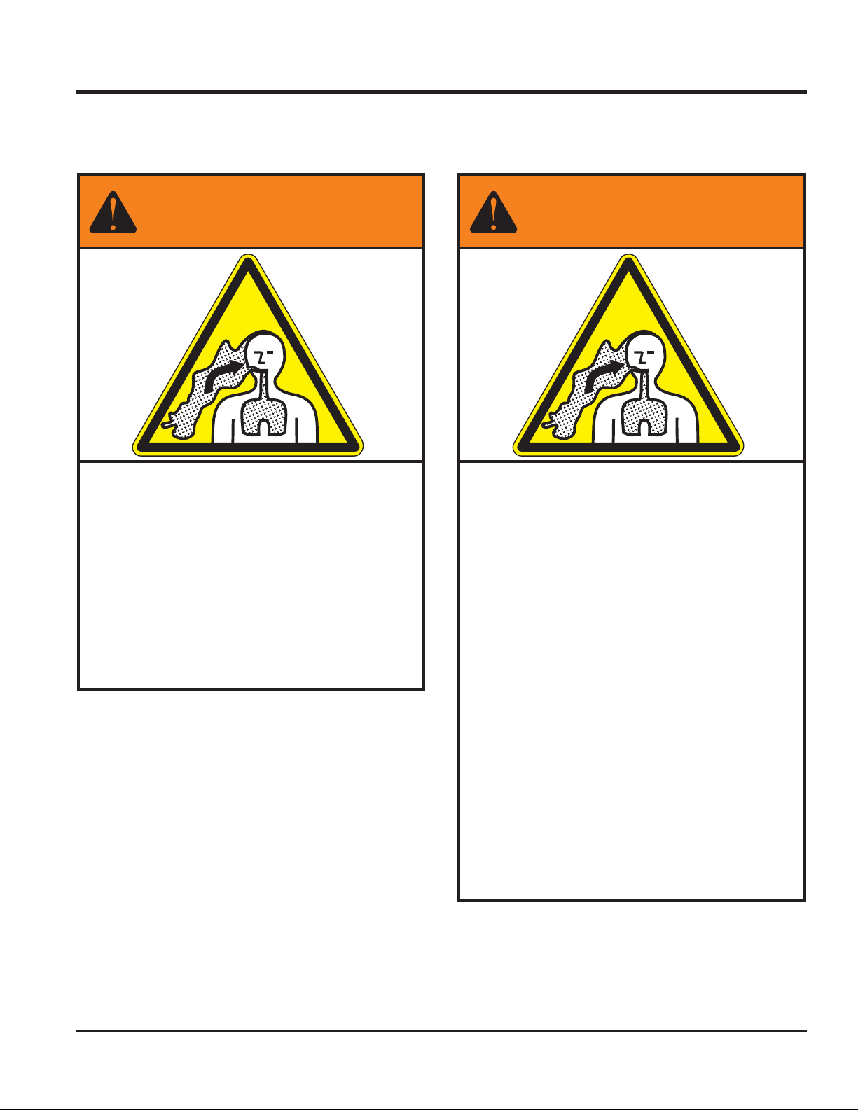
SILICOSIS/RESPIRATORY WARNINGS
WARNING
SILICOSIS WARNING RESPIRATORY HAZARDS
Grinding/cutting/drilling of masonry, concrete, metal and
other materials with silica in their composition may give
off dust or mists containing crystalline silica. Silica is a
basic component of sand, quartz, brick clay, granite and
numerous other minerals and rocks. Repeated and/or
substantial inhalation of airborne crystalline silica can
cause serious or fatal respiratory diseases, including
silicosis. In addition, California and some other
authorities have listed respirable crystalline silica as a
substance known to cause cancer. When cutting such
materials, always follow the respiratory precautions
mentioned above.
WARNING
Grinding/cutting/drilling of masonry, concrete, metal and
other materials can generate dust, mists and fumes
containing chemicals known to cause serious or fatal
injury or illness, such as respiratory disease, cancer,
birth defects or other reproductive harm. If you are
unfamiliar with the risks associated with the particular
process and/or material being cut or the composition of
the tool being used, review the material safety data
sheet and/or consult your employer, the material
manufacturer/supplier, governmental agencies such as
OSHA and NIOSH and other sources on hazardous
materials. California and some other authorities, for
instance, have published lists of substances known to
cause cancer, reproductive toxicity, or other harmful
effects.
Control dust, mist and fumes at the source where
possible. In this regard use good work practices and
follow the recommendations of the manufacturers or
suppliers, OSHA/NIOSH, and occupational and trade
associations. Water should be used for dust
suppression when wet cutting is feasible. When the
hazards from inhalation of dust, mists and fumes cannot
be eliminated, the operator and any bystanders should
always wear a respirator approved by NIOSH/MSHA for
the materials being used.
MP1 SERIES MASONRY SAWS — OPERATION AND PARTS MANUAL — REV. #1 (03/29/10) — PAGE 3
Page 4

TABLE OF CONTENTS
MP1 SERIES MASONRY SAW
Proposition 65 Warning ............................................. 2
Silicosis/Respiratory Warnings .................................. 3
Table Of Contents ..................................................... 4
Parts Ordering Procedures ....................................... 5
Safety Message Alert Symbols .............................. 6-7
Rules For Safe Operation .................................... 8-10
Operation and Safety Decals .................................. 11
Specifications .......................................................... 12
Dimensions ............................................................. 13
General Information ................................................ 14
Controls and Components ................................. 16-17
Electric Motor Components .................................... 18
Engine Components ............................................... 19
Pre-Setup (Electric) ............................................ 20-23
Pre-Setup (Gasoline) ......................................... 24-25
Operation (Electric) ............................................ 26-27
Operation (Electric) ............................................ 28-29
Maintenance ...................................................... 30-33
Electric Motor Wiring Diagram ................................ 34
Troubleshooting (Blade) .......................................... 36
Troubleshooting (Electric Motor) ............................. 37
Troubleshooting (Gasoline Engine) ................... 38-39
Explanation of Code In Remarks Column............... 40
Suggested Spare Parts ........................................... 41
HONDA GX160K1QXC9
GASOLINE ENGINE
COMPONENT DRAWINGS
NOTE
PAGE 4 — MP1 SERIES MASONRY SAWS — OPERATION AND PARTS MANUAL — REV. #1 (03/29/10)
Page 5
PARTS ORDERING PROCEDURES
Ordering parts has never been easier!
Choose from three easy options:
January 1
Effective:
st
, 2006
Best Deal!
Order via Internet (Dealers Only):
Order parts on-line using Multiquip’s SmartEquip website!
N View Parts Diagrams
N Order Parts
N Print Specification Information
Goto www.multiquip.com and click on
Order Parts
Order via Fax (Dealers Only):
All customers are welcome to order parts via Fax.
Domestic (US) Customers dial:
1-800-6-PARTS-7 (800-672-7877)
Non-Dealer Customers:
Contact your local Multiquip Dealer for
parts or call 800-427-1244 for help in
locating a dealer near you.
to log in and save!
Order via Phone:
If you have an MQ Account, to obtain a Username
and Password, E-mail us at: parts@multiquip.
com.
To obtain an MQ Account, contact your
District Sales Manager for more information.
Use the internet and qualify for a 5% Discount
on Standard orders for all orders which include
complete part numbers.*
Note: Discounts Are Subject To Change
Fax your order in and qualify for a 2% Discount
on Standard orders for all orders which include
complete part numbers.*
Note: Discounts Are Subject To Change
Domestic (US) Dealers Call:
1-800-427-1244
International Customers should contact
their local Multiquip Representatives for
Parts Ordering information.
When ordering parts, please supply:
R Dealer Account Number
R Dealer Name and Address
R Shipping Address (if different than billing address)
R Return Fax Number
R Applicable Model Number
R Quantity, Part Number and Description of Each Part
NOTICE
All orders are treated as Standard Orders and will
ship the same day if received prior to 3PM PST.
R Specify Preferred Method of Shipment:
UPS/Fed Ex DHL
N Priority One Tr uck
N Ground
N Next Day
N Second/Third Day
www.multiquip.com
WE ACCEPT ALL MAJOR CREDIT CARDS!
MP1 SERIES MASONRY SAWS — OPERATION AND PARTS MANUAL — REV. #1 (03/29/10) — PAGE 5
Page 6
SAFETY MESSAGE ALERT SYMBOLS
FOR YOUR SAFETY AND THE SAFETY OF OTHERS!
Safety precautions should be followed at all times when operating
this equipment. Failure to read and understand the Safety
Messages and Operating Instructions could result in injury to
yourself and others.
This Owner's Manual has been
developed to provide complete
instructions for the safe and
NOTE
Before using this MASONRY SAW, ensure that the operating
individual has read and understands all instructions in this
manual.
efficient operation of the
MULTIQUIP MP1. For engine
maintenance information, please
refer to the engine manufacturers
instructions for data relative to its
safe operation.
HAZARD SYMBOLS
SAFETY MESSAGE ALERT SYMBOLS
The three (3) Safety Messages shown below will inform you
about potential hazards that could injure you or others. The
Safety Messages specifically address the level of exposure to
the operator, and are preceded by one of three words: DANGER,
WARNING, or CAUTION.
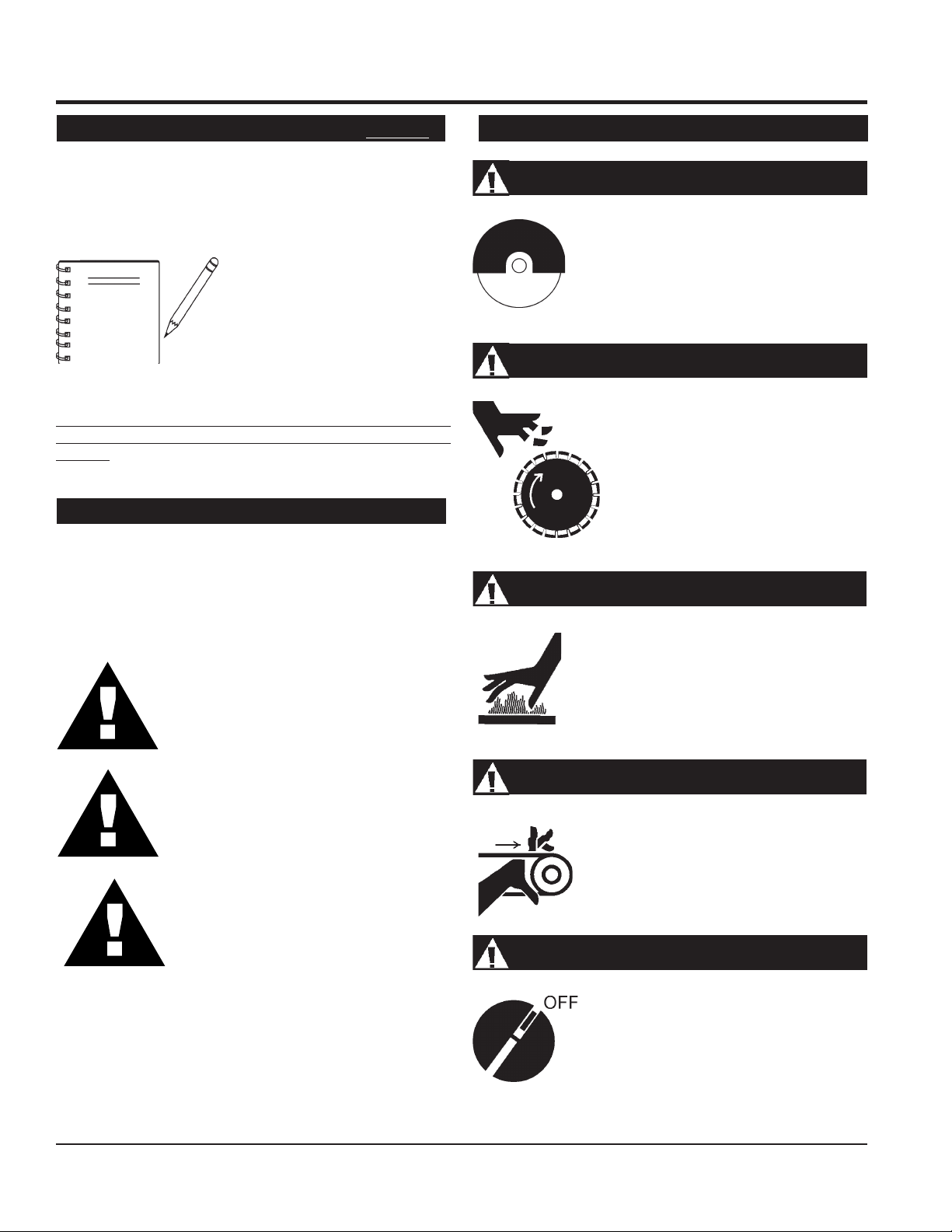
DANGER: You WILL be KILLED or
SERIOUSLY injured if you DO NOT follow
directions.
Guards and Covers In Place
NEVER operate the saw without blade guards
and covers in place. Adhere to safety
guidelines ANSI American National
Standards Institute, OSHA or other applicable
local regulations.
Rotating Blade
Rotating blade can cut and crush. Keep
hands and feet clear.
Burn Hazards
Engine components can generate extreme heat.
To prevent burns, DO NOT touch these areas
while the engine is running or immediately after
operations. NEVER operate the engine with
heat shields or heat guards removed.
Rotating Parts
WARNING: You CAN be KILLED or
SERIOUSLY injured if you DO NOT follow
directions.
NEVER operate equipment with covers, or
guards removed. Keep fingers,
and
clothing
prevent injury.
away from all moving parts to
CAUTION: You CAN be injured if you
DO NOT follow directions.
Accidental Starting
Potential hazards associated with masonry saw operation will
be referenced with "
this manual, and will be referenced in conjunction with Safety
"
Message Alert Symbols
Hazard Symbols
".
" which appear throughout
PAGE 6 — MP1 SERIES MASONRY SAWS — OPERATION AND PARTS MANUAL — REV. #1 (03/29/10)
ALWAYS place the engine ON/OFF
switch in the OFF position, when the saw
is not in use.
hands, hair
Page 7
SAFETY MESSAGE ALERT SYMBOLS
Over Speed Conditions
NEVER tamper with the factory settings of the
engine governor or settings. Personal injury
and damage to the engine or equipment can
result if operating in speed ranges above
maximum allowable.
Respiratory Hazard
ALWAYS wear approved respiratory protection
that complies with ANSI-Z87.1.
Sight and Hearing hazard
ALWAYS wear approved eye and hearing
protection that complies with ANSI-Z87.1
HAZARD SYMBOLS - Gasoline Powered Models
Lethal Exhaust Gases
Engine exhaust gases contain poisonous
carbon monoxide. This gas is colorless and
odorless, and can cause death if inhaled.
NEVER operate this equipment in a confined
area or enclosed structure that does not
provide ample free flow air.
Explosive Fuel
Gasoline is extremely flammable, and its
vapors can cause an explosion if ignited. DO
NOT start the engine near spilled fuel or
combustible fluids. DO NOT fill the fuel tank
while the engine is running or hot. DO NOT
overfill tank, since spilled fuel could ignite if it
comes into contact with hot engine parts or
sparks from the ignition system. Store fuel in
approved containers, in well-ventilated areas
and away from sparks and flames. NEVER
use fuel as a cleaning agent.
Equipment Damage Messages
NOTE
Other important messages are provided throughout this manual
to help prevent damage to your concrete saw, other property, or
the surrounding environment.
This
saw
, other property, or the
surrounding environment could be
damaged if you do not follow
instructions.
MP1 SERIES MASONRY SAWS — OPERATION AND PARTS MANUAL — REV. #1 (03/29/10) — PAGE 7
Page 8
RULES FOR SAFE OPERATION
CAUTION:
Failure to follow instructions in this manual may
lead to serious injury or even death! This
equipment is to be operated by trained and
qualified personnel only! This equipment is
for industrial use only.
The following safety guidelines should always be used when
operating the MP1 SAW. Unless otherwise noted, these
guidelines refer to saws with gasoline powered engines.
SAFETY
■
DO NOT operate or service this equipment
before reading this entire manual.
■
This equipment should not be operated by
persons under 18 years of age.
■
NEVER operate the saw without proper protective
clothing, shatterproof glasses, steel-toed boots
and other protective devices required by the job.
SAFETY - GASOLINE POWERED ENGINES
■
NEVER touch the hot exhaust
manifold, muffler or cylinder. Allow
these parts to cool before servicing
the saw.
■
High Temperatures – Allow the engine to cool before adding
fuel or performing service and maintenance functions. Contact
hot!
with
■
The engine of this saw (
adequate free flow of cooling air. NEVER operate the saw in
components can cause serious burns.
gasoline model only
any enclosed or narrow area
where free flow of the air is
restricted. If the air flow is
restricted it will cause serious
damage to the saw's engine
and may cause injury to
people. Remember the
saw's engine gives off
DEADLY
gas.
) requires an
carbon monoxide
■
NEVER operate this equipment when not
feeling well due to fatigue, illness or taking
medicine.
■
NEVER operate the saw under the
influence or drugs or alcohol.
■
NEVER use accessories or attachments,
which are not recommended by Multiquip
for this equipment. Damage to the equipment and/or injury to
user may result.
■
Manufacturer does not assume responsibility for any accident
due to equipment modifications. Unauthorized equipment
modification will void all warranties.
■
Whenever necessary, replace nameplate, operation and
safety decals when they become difficult read.
■
ALWAYS check the saw for loosened threads or bolts before
starting.
■
NEVER operate the saw in an explosive atmosphere where
fumes are present or near combustible materials. An explosion
or fire could result causing severe
bodily harm or even
death.
■
NEVER use fuel as a cleaning agent.
■
■
■
■
■
■
■
ALWAYS stop the engine before servicing, adding fuel and
oil.
ALWAYS refuel in a well-ventilated
area, away from sparks and open
flames.
ALWAYS use extreme caution when
working with flammable liquids. When
refueling, stop the engine and allow it to cool.
NEVER
machine. Fire or explosion could result from
fuel vapors
engine.
Topping-off to filler port is dangerous, as it tends to spill fuel.
ALWAYS service air cleaner frequently to prevent carburetor
malfunction.
NEVER run the engine without the air filter. Severe engine
damage could occur. (Gasoline powered engines)
smoke
around or near the
, or if fuel is spilled on a
hot!
PAGE 8 — MP1 SERIES MASONRY SAWS — OPERATION AND PARTS MANUAL — REV. #1 (03/29/10)
Page 9
RULES FOR SAFE OPERATION
SAFETY - ELECTRIC POWERED MODELS
■
ALWAYS connect the motor to a power source in compliance
with all local electrical codes. This must be performed by a
qualified electrician.
■
ALWAYS use only outdoor approved GROUNDED extension
cords.
■
MAKE CERTAIN the power cord/extension cord is free from
damage and that the grounding circuit is operational.
■
MAKE CERTAIN the extension cord used is intended to be
used in the environment you will be using it in. If an extension
is used, NEVER submerge the connection in water. To reduce
the risk of electrical shock, always make water-tight
connections.
■
MAKE CERTAIN the "ON/OFF" switch is in the "OFF" position
before plugging in the power cord/extension cord to avoid
accidental starting.
■
ALWAYS stop the motor before servicing. MAKE CERTAIN
the motor is stopped and turned "OFF" at the switch, and the
power cord is disconnected from the power source.
■
Use only the guage wire and length of cord recommended
for the motor size.
■
When cutting, ALWAYS be aware of the location of the cord.
BLADE SAFETY
■
■
■
■
WARNING
■
ALWAYS check to make sure that the
operating area is clear before starting the
engine.
Use appropriate blades manufactured for use on masonry
saws.
WARNING
Always inspect blades before each
use. The blade should exhibit no
cracks, dings, or flaws in the steel
centered core and/or rim. Center
(arbor) hole must be undamaged and
true.
Examine blade flanges for damage, excessive wear and
cleanliness before mounting blade. Blade should fit snugly
on the shaft and against the inside/outside blade flanges.
Ensure the blade is marked with an operating speed greater
than the blade shaft speed of the saw.
GENERAL SAFETY
■
ALWAYS read, understand, and follow procedures in
Operator's Manual before attempting to operate equipment.
■
ALWAYS be sure the operator is familiar with proper safety
precautions and operating techniques before using the saw.
■
NEVER leave the machine
■
Block the unit when leaving or when using on a slope.
■
ALWAYS check to make sure that the operating area is clear
before starting the engine.
■
Maintain this equipment in a safe operating condition at all
times.
■
AVOID wearing jewelry or loose fitting clothing that may snag
on the controls or moving parts, this can cause a serious
injury.
■
ALWAYS keep clear of
operating or the saw.
■
ALWAYS store equipment properly when it is not being used.
Equipment should be stored in a clean, dry location out of
the reach of children.
■
NEVER use accessories or attachments which are not
recommended by the manufacturer for this equipment.
Damage to the equipment and/or injury to user may result.
unattended
rotating
or
while running.
moving parts
while
■
■
■
■
■
■
■
■
Only cut the material that is specified by the blade. Read the
specifications of the blade to ensure the proper tool has been
matched to the material being cut.
Always keep blade guards in place.
Exposure of the blade must not
exceed 180 degrees.
NEVER touch or try to stop a moving
blade with your hands. ALWAYS
keep hands clear of the blade.
Ensure that the blade does not come
into contact with the ground or surface
during transportation. DO NOT drop the blade on ground or
surface.
The engine governor is designed to permit maximum engine
speed in a no-load condition. Speeds that exceed this limit
may cause the blade to exceed the maximum safe allowable
speed.
Ensure that the blade is mounted for proper operating
direction.
Keep all inexperienced and unauthorized people away from
the equipment at all times.
ALWAYS use or operate the saw on a level surface to prevent
the saw from tipping.
MP1 SERIES MASONRY SAWS — OPERATION AND PARTS MANUAL — REV. #1 (03/29/10) — PAGE 9
Page 10
RULES FOR SAFE OPERATION
SAW MAINTENANCE (CLEANING)
■
ALWAYS clean the saw before maintenance or repair.
■
DO NOT use aggressive cleaners (i.e. containing solvents).
DO NOT use high pressure water jets, aggressive detergents
or solutions and liquids with a temperature exceeding 86 F.
Use a fluff-free cloth only.
■
Use a cloth which may be lightly moistened only for removing
dust and dirt. Hard packed dirt can be removed with a
brush.
■
NEVER let water, cleaning liquid or vapor penetrate into the
electric motor, connectors, plugs, and switches. When
cleaning cover all apertures or openings on all electrical
components.
■
ALWAYS use a soft, low-pressure water jet and a brush to
rinse dirt and incrustations away. Be particularly careful not
to spray water on sensitive parts of of the saw (e.g. electric
motor, ON/OFF switch). Clean the motor and ON/OFF switch
moist
by wiping with a
■
DO NOT rinse the bearings of the drive elements (gasoline
model only).
cloth.
soft
SAW TRANSPORTATION SAFETY
■
■
■
■
EMERGENCIES
■
■
Use an appropriate lifting equipment to ensure the safe
movement of the saw.
DO NOT use the handles as lifting points.
Safeguard against extreme saw attitudes relative to level.
An engine tipped to extreme angles may cause oil to gravitate
into the cylinder head making the engine start difficult.
(Gasoline powered engines)
NEVER transport the saw with the blade mounted.
ALWAYS know the
location of the nearest
fire extinguisher
ALWAYS know the location of the
nearest and
.
first aid kit
.
■
In emergencies
nearest phone or
Also know the phone numbers of the nearest
ambulance, doctor
information will be invaluable in the case of an
emergency.
always
know the location of the
keep a phone on the job site
and
fire department
.
. This
PAGE 10 — MP1 SERIES MASONRY SAWS — OPERATION AND PARTS MANUAL — REV. #1 (03/29/10)
Page 11

NOTES
MP1 SERIES MASONRY SAWS — OPERATION AND PARTS MANUAL — REV. #1 (03/29/10) — PAGE 11
Page 12
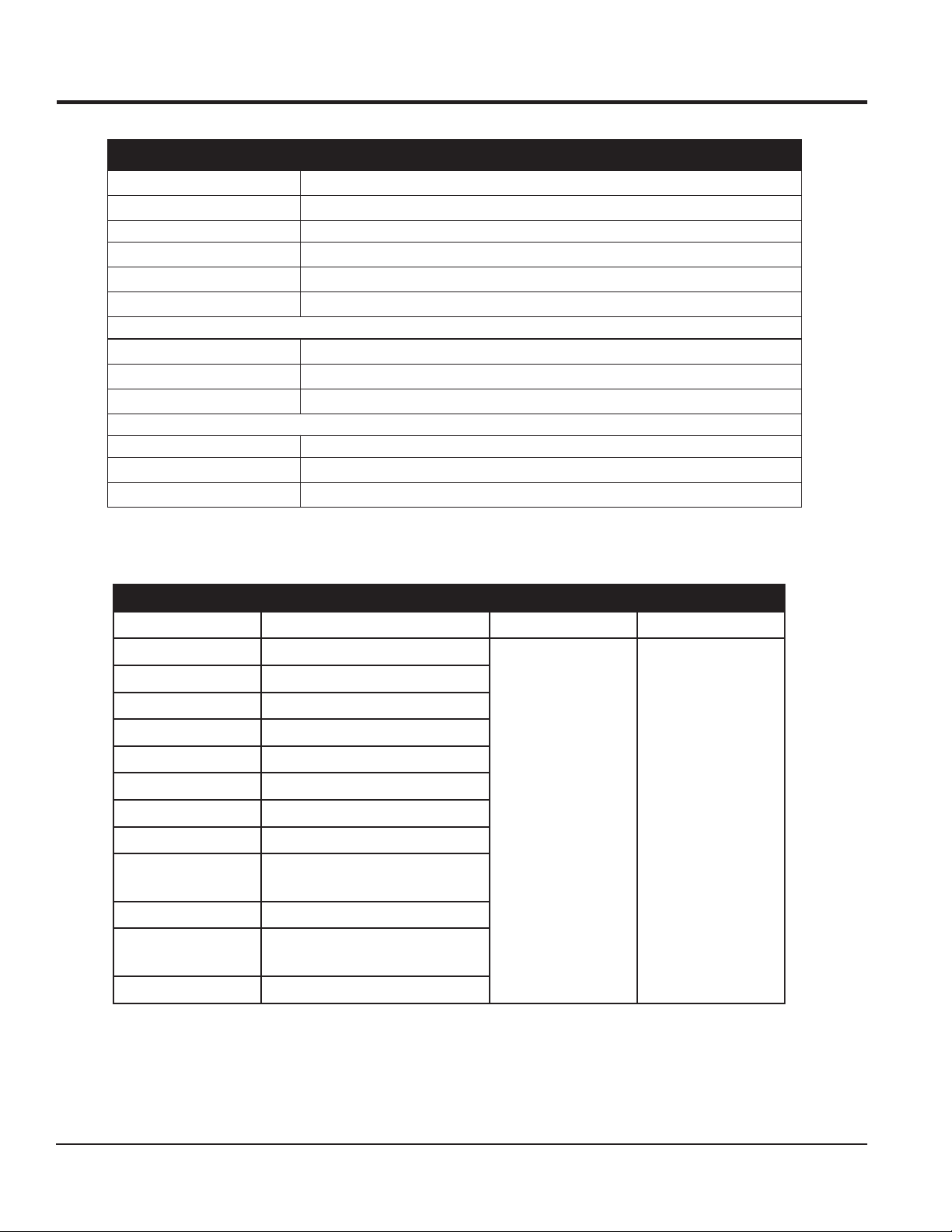
SPECIFICATIONS (SAW/ENGINE)
ELBATWAS1PM.1SNOITACIFICEPS
snoisnemiD
thgieWetamixorppA
).gK57(.sbl561
)mc85.86xmc28.38xmc521.111("72x"33x"57.34
deepSrotoMcirtcelE
deepSedalB
MPR8852
pmuPretaW
)2elbaTeeS(MPR0543
detcetorpyllamrehT,zH06/V511
)enilosaG(enignE
deepSedalB
pmuPretaW
LARENEG
yticapaCedalB
htpeDgnittuC
Table 2. MP1 Electric Motor/Engine Specifications
Saw Model MP1H MP115E MP120E
Engine/Motor Honda GX160K1QXC9
Type 4-Stroke OHV Single Cylinder
MPR0082
205-70852tiKlanoitpO
mumixamedalb.ni41
edalb.ni41htiw.ni5
)2elbaTeeS(adnoH,delooCriA,rednilyCelgniS,elcyc4PH5.5
Bore xStroke 2.7 x 1.8in. (68 x 45mm)
Displacement 9.9 cu. in. (163 cc)
Max Output 5.4 bhp (4.0 KW) @ 3600 rpm
Fuel Tank Cap. 0.95 US Gal. (3.6 liters)
Fuel Unleaded Gasoline
Lube Oil Cap. 0.63 US Qt. (0.60 liters)
Speed Control
Method
Starting Method Recoil Start
Dimension
Dry Net Weight 33.1 lbs. (15.0 kg)
Centrifugal Fly-Weight type
12.0 x 14.3 x 13.2 in
(304 x 362 x 335mm)
1.5 HP
Heavy Duty Electric
115/230V
Single Phase
60Hz
Dual Voltage
Amps F.L
17.2/8.6
2.0 HP
Heavy Duty Electric
115/230V
Single Phase
60Hz
Dual Voltage
Amps F.L
16.8/8.4
DANGER
PAGE 12 — MP1 SERIES MASONRY SAWS — OPERATION AND PARTS MANUAL — REV. #1 (03/29/10)
Page 13
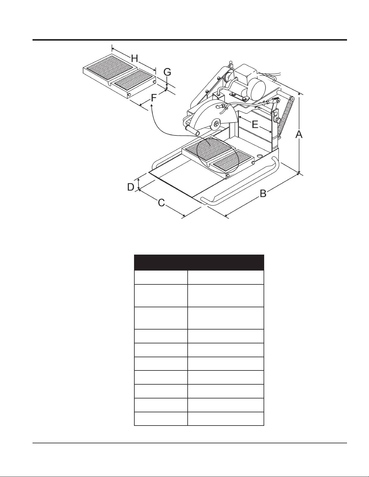
DIMENSIONS
Figure 1. Dimensions
.FERSNOISNEMID
A
)rotomcirtcele(
A
)enigneenilosag(
B)mc601(.ni0.24
C)mc6.85(.ni0.72
D)mc79.31(.ni5.5
E)mc8.63(.ni5.41
F)mc2.92(.ni5.11
G)sretem53.6(.ni5.2
SNOISNEMID.3ELBAT
)mc47(.ni0.92
)mc47(.ni0.92
H)sretem2.84(.ni0.91
MP1 SERIES MASONRY SAWS — OPERATION AND PARTS MANUAL — REV. #1 (03/29/10) — PAGE 13
Page 14

GENERAL INFORMATION
MP1 MASONRY SAW
The MP1 masonry saw is designed for vigorous wet-cutting
masonry applications. The heavy-duty aluminum conveyor cart
and ball bearing roller wheels ensure material stability and
smooth travel. In addition a reinforced jig-welded steel frame
provides rigidity for cutting accuracy and long service life.
This saw is available with either an
engine
1.5 HP or 2.0 HP with overload protection. Each motor can
operate at either 115 VAC or 230 VAC. The electric motor input
voltage is selectable by means of a toggle switch. Always make
sure that the input voltage being supplied to the motor matches
the position of the voltage selector toggle switch located on top
of the motor.
If desired, the MP1 saw can be configured with a 5.5 HP Honda
GX160 gasoline engine.
All MP1 models include a high flow water pump, cutting jig, water
hoses and associated plumbing to enable the operator to begin
wet cutting.
DRY CUTTING APPLICATIONS
The MP1 masonry saw is shipped from the factory for wet-cutting
saw applications, however it can be used for dry-cutting saw
applications (see dry-cutting saw applications in this manual).
The most import thing to remember is to
pump
failure to disconnect the pump (when running dry) will cause
pump failure. NEVER! have the water pump engaged when dry
cutting applications are involved.
BLADE APPLICATIONS
. The heavy duty electric motors are available in either
. The water pump is cooled by the flow of water, and
electric motor
disconnect the water
or a
gasoline
ACCESSORIES/REPLACEMENT PARTS
If desired the MP1 masonry saw can be equipped with a scissors
type support stand P/N TRAK14SS, this stand is ideal when the
saw needs to be transported and placed on a secure reliable
platform.
OVERVIEW OF FEATURES
■
1.5 or 2.0 HP, 115/230 VAC , 60 Hz heavy duty electric motors
with overload protection.
■
5.5 HP Honda GX160 gasoline engine.
■
14-inch blade capacity provides 5-inch depth of cut.
■
Rugged aluminum conveyor cart for optimum stability.
■
Open back design permits capability of cutting large
materials.
■
Ergonomically designed cutting head provides operator
relief in high tempo operations.
■
Mounted carrying handles for easy transportation.
■
Rubber-matted cutting table helps hold the material being
cut in place while resisting vibrations for smoother cuts with
less chipping.
■
Cutting table marked in inches and centimeters (ruler) for
precision cuts.
■
Stay-level blade guard for operator safety.
■
Rigid steel frame minimizes vibrations and assures accurate
cutting.
■
Mechanical Water Pump Kit (Gasoline Model Only)
■
Electric Submersible Water Pump Kit (Electric Models Only).
This saw has been designed to incorporate the use of diamond
blades as the cutting tool. The optimum performance of this saw
is best evidenced by using 14-inch (356 mm) diamond blades
that match the material being cut. Ask your dealer, or call
MULTIQUIP about your specific cutting application.
PAGE 14 — MP1 SERIES MASONRY SAWS — OPERATION AND PARTS MANUAL — REV. #1 (03/29/10)
Page 15

NOTES
MP1 SERIES MASONRY SAWS — OPERATION AND PARTS MANUAL — REV. #1 (03/29/10) — PAGE 15
Page 16
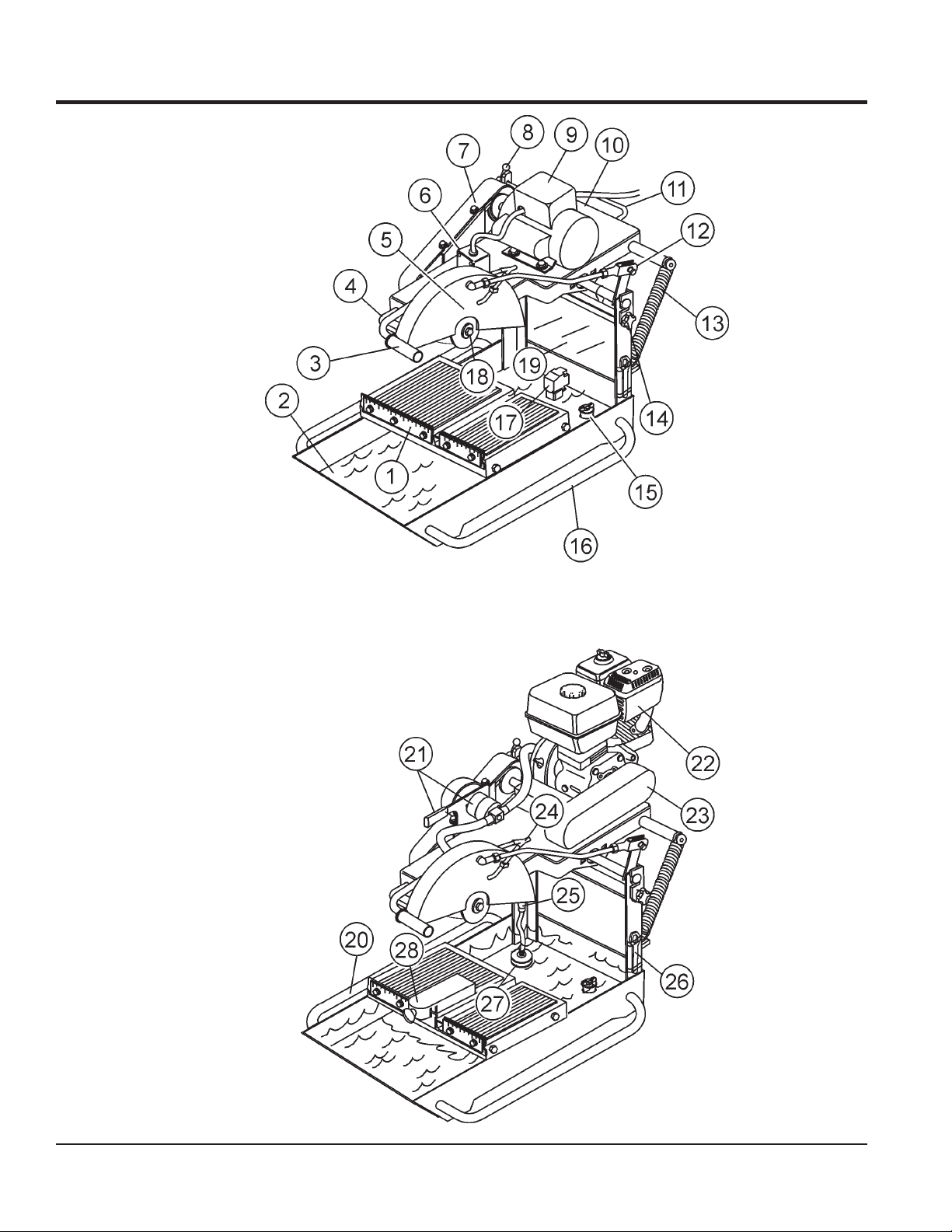
CONTROLS AND COMPONENTS
Figure 2. MP1 Saw (Electric/Gasoline)
PAGE 16 — MP1 SERIES MASONRY SAWS — OPERATION AND PARTS MANUAL — REV. #1 (03/29/10)
Page 17

CONTROLS AND COMPONENTS
Figure 2 shows the location of the basic controls or components
for the MP1 saw. Listed below is a brief explanation of each
control or component.
1. Ruler Backstop – When cutting, place material against
backstop. Use measurement rail (ruler) to determine where
material is to be cut.
16. Carrying Handle (Tray) – Grip this handle (right-side) to
trasport the saw.
17. Electric Water Pump – For best results place the pump
between the splash shield and the rear of the water tray.
This is for electric models only. Plug water pump power
cord into AC receptacle on electric motor conduit box.
NEVER
2. Water Tray – When wet cutting is required, fill with clean
fresh water. Make sure submersible is totally immersed in
water.
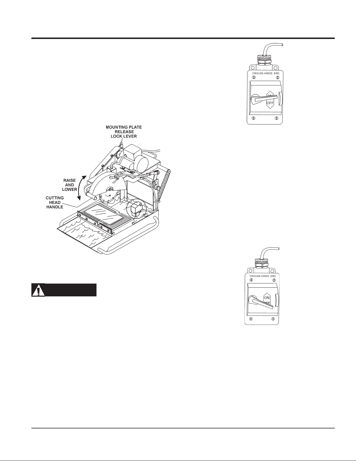
3. Cutting Head Handle – Grab hold of this handle to move
up
the cutting blade head either
cutting head, release the mounting plate release/lock lever.
4. Carrying Handle (Head) – Grip this handle (front) to lift
the mounting plate.
5. Blade Guard – Protects the user from the cutting blade.
NEVER
6. Power ON/OFF Box – This box is used on
models
position. Place in the OFF position to shut-down the saw.
7. V-belt Cover – Remove this cover to access the drive Vbelt.
8. Mounting Plate Release/Lock Lever – Push this lever
backwards to release
the cutting head to move either up or down. Push the lever
forward to lock
9. Electric Motor/Conduit Box– This unit uses 2 different
types of electric motors and voltages (see Table 2). Always
make sure the voltage selector switch has been set to the
correct position for the voltage being supplied to the motor.
Plug the water pump (electric models only) power cord
into the AC receptacle located on the conduit box.
10. Mounting Plate – Supports the electric motor/gasoline
engine. Plate has slotted holes for horizontal (right-side)
and vertical (left-side) adjustment of cutting head.
11. Carrying Handle (Head) – Grip this handle (rear) to lift
the mounting plate.
12 . Tie Rod – The tie rod length has been set at the factory for
best blade guard position for the majority of the cutting that
will be done.
13. Spring Tensioner – Allows for an easy up and down
movement of the mounting plate.
operate the saw with the blade guard removed.
saws only
NEVER
. To turn on the saw place in the ON
operate the saw with the V-belt cover removed.
the mounting plate. This will allow
the mounting plate in place.
or down. To move the
electric
18. Spindle Bolt/Outside Blade Flange – When mounting
of the cutting blade is required, remove the spindle bolt
and outside blade flange. Align cutting blade with inside
flange arbor and reassemble spindle and outside blade
flange.
19. Splash Guard – Keeps water and debris from leaving the
water tray.
20. Carrying Handle (Tray) – Grip this handle (left-side) to
trasport the saw.
21. Mechanical Water Pump – This pump is used on gasoline
models only. Saw is shipped from the factor for wet cutting
applications (pump handle down). Place pump handle
upwards to disengage pump.
22. Engine – The gasoline model saws uses a 5.5 HP Honda
GX160, 4-stroke, OHV, single cylinder, air cooled gasoline
engine.
23. V-belt Cover (Gasoline Only) – Remove this cover to
access the engine shaft-side V-belt.
saw with the V-belt cover removed.
24. Water Lines – Replace the clear vinyl tubing water lines
when they become brittle, worn or clogged. Water kits are
available through your dealer.
25. Priming Bulb – Squeeze this bulb to prime the mechanical
water pump (gasoline models only).
26. Blade Wrench – Use this tool to mount and remove cutting
blade.
27. Strainer – For best results place the strainer between the
splash shield and the rear of the water tray. This is for
gasoline models only.
be immersed in water.
28. Miter Box – For angled cuts, place the lip of the miter box
on the measurement rail with the threaded thumb knob
facing you and tighten.
run pump dry. Pump must be immersed in water.
NEVER
NEVER
run pump dry. Strainer must
run pump dry.
NEVER
operate the
14. Mounting Plate Lock/Release Knobs – Turn knob (2)
clockwise to release the mounting plate. Turn counterclockwise to tighten.
15. Stopper – Place stopper in tray when filling with water.
MP1 SERIES MASONRY SAWS — OPERATION AND PARTS MANUAL — REV. #1 (03/29/10) — PAGE 17
Page 18
MP1 — ELECTRIC MOTOR COMPONENTS
Figure 3. Electric Motor Components
PAGE 18 — MP1 SERIES MASONRY SAWS — OPERATION AND PARTS MANUAL — REV. #1 (03/29/10)
Page 19
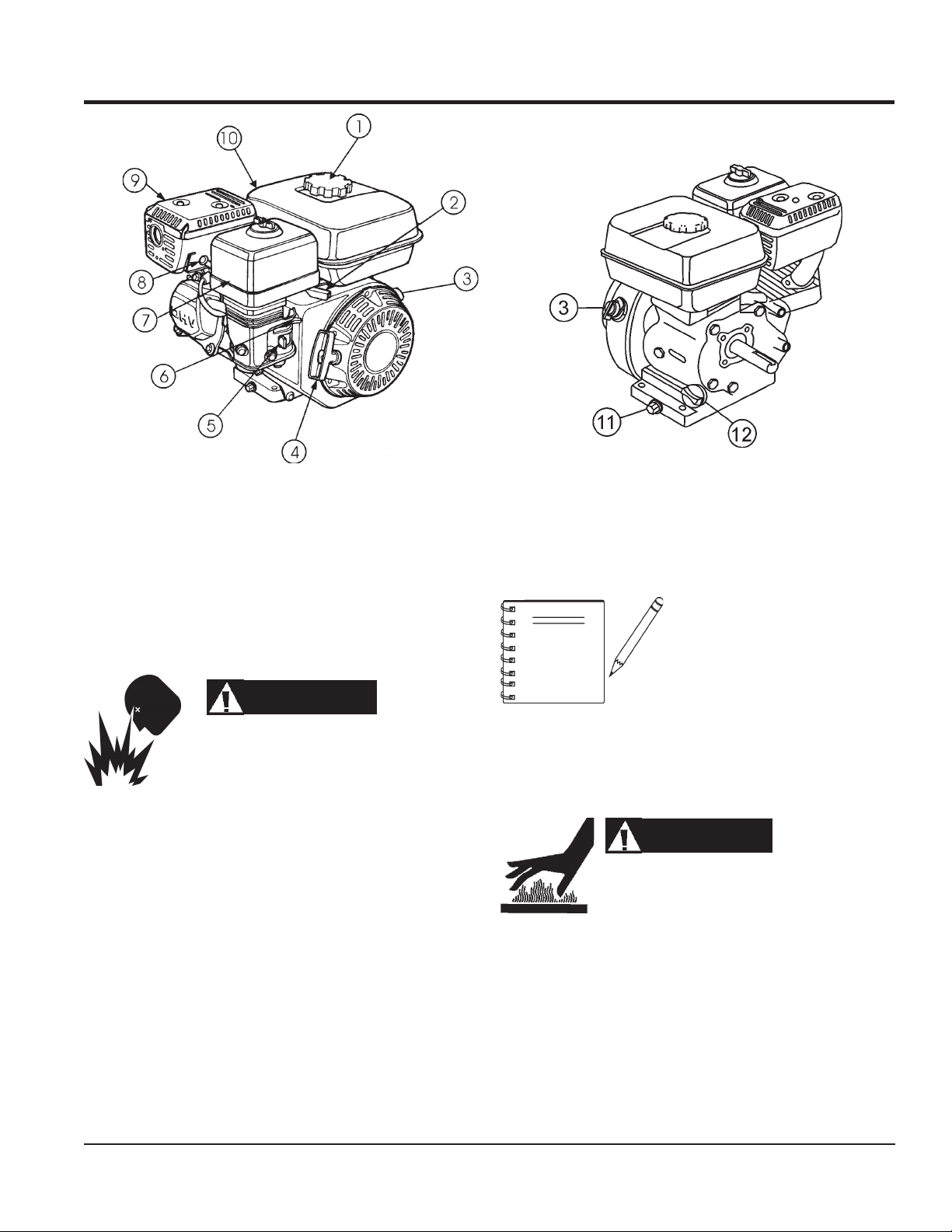
MP1 — ENGINE COMPONENTS
Figure 4. Engine Controls and Components
INITIAL SERVICING-GASOLINE ENGINE
The engine (Figure 4) must be checked for proper lubrication and
filled with fuel prior to operation. Refer to the manufacturers engine
manual for instructions & details of operation and servicing.
1. Fuel Filler Cap – Remove this cap to add unleaded
gasoline to the fuel tank. Make sure cap is tightened
securely. DO NOT over fill.
7. Air Cleaner – Prevents dirt and other debris from entering
the fuel system. Remove wing-nut on top of air filter
cannister to gain access to filter element.
NOTE
DANGER
Adding fuel to the tank should be done only when
the engine is stopped and has had an opportunity
to cool down. In the event of a fuel spill, DO NOT
attempt to start the engine until the fuel residue has been completely
wiped up, and the area surrounding the engine is dry.
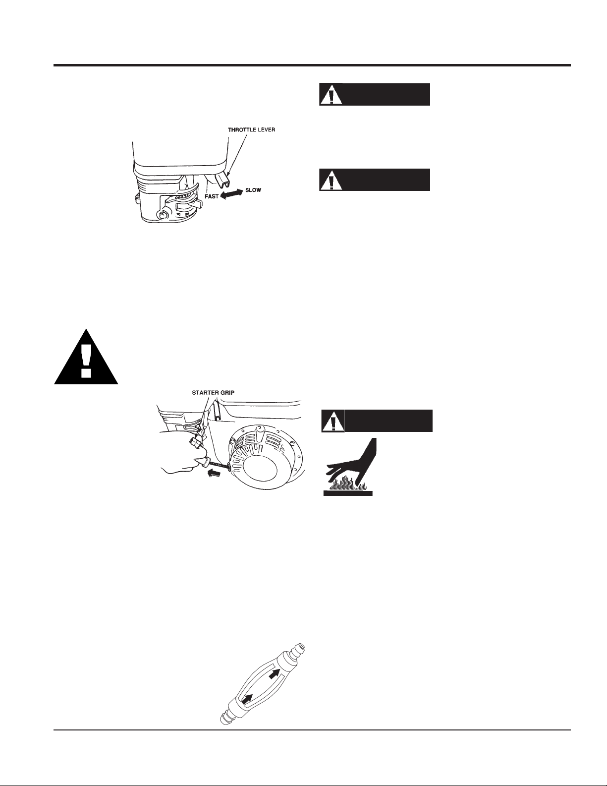
2. Throttle Lever – Used to adjust engine RPM speed (lever
SLOW
advanced forward
FAST
).
3. Engine ON/OFF Switch – ON position permits engine
starting, OFF position stops engine operations.
4. Recoil Starter (pull rope) – Manual-starting method. Pull
the starter grip until resistance is felt, then pull briskly and
smoothly.
5. Fuel Valve Lever – OPEN to let fuel flow, CLOSE to stop
the flow of fuel.
6. Choke Lever – Used in the starting of a cold engine, or in
cold weather conditions. The choke enriches the fuel
mixture.
, lever back toward operator
8. Spark Plug – Provides spark to the ignition system. Set
spark plug gap to 0.6 - 0.7 mm (0.028 - 0.031 inch) Clean
spark plug once a month.
9. Muffler – Used to reduce noise and emissions
operating. NEVER operate the engine with the muffler removed.
10. Fuel Tank – Holds unleaded gasoline. For additional
information refer to engine owner's manual.
11. Oil Drain Bolt – Drain used oil while the engine is warm.
12. Oil Level Cap and Dipstick – Check engine oil with
engine stopped and in a level position.
Operating the engine without an
air filter, with a damaged air filter,
.
or a filter in need of replacement
will allow dirt to enter the engine,
causing rapid engine wear.
WARNING
Engine components can generate extreme heat.
To prevent burns, DO NOT touch these areas
while the engine is running or immediately after
MP1 SERIES MASONRY SAWS — OPERATION AND PARTS MANUAL — REV. #1 (03/29/10) — PAGE 19
Page 20
PRE-SETUP (ELECTRIC)
PRE-SETUP
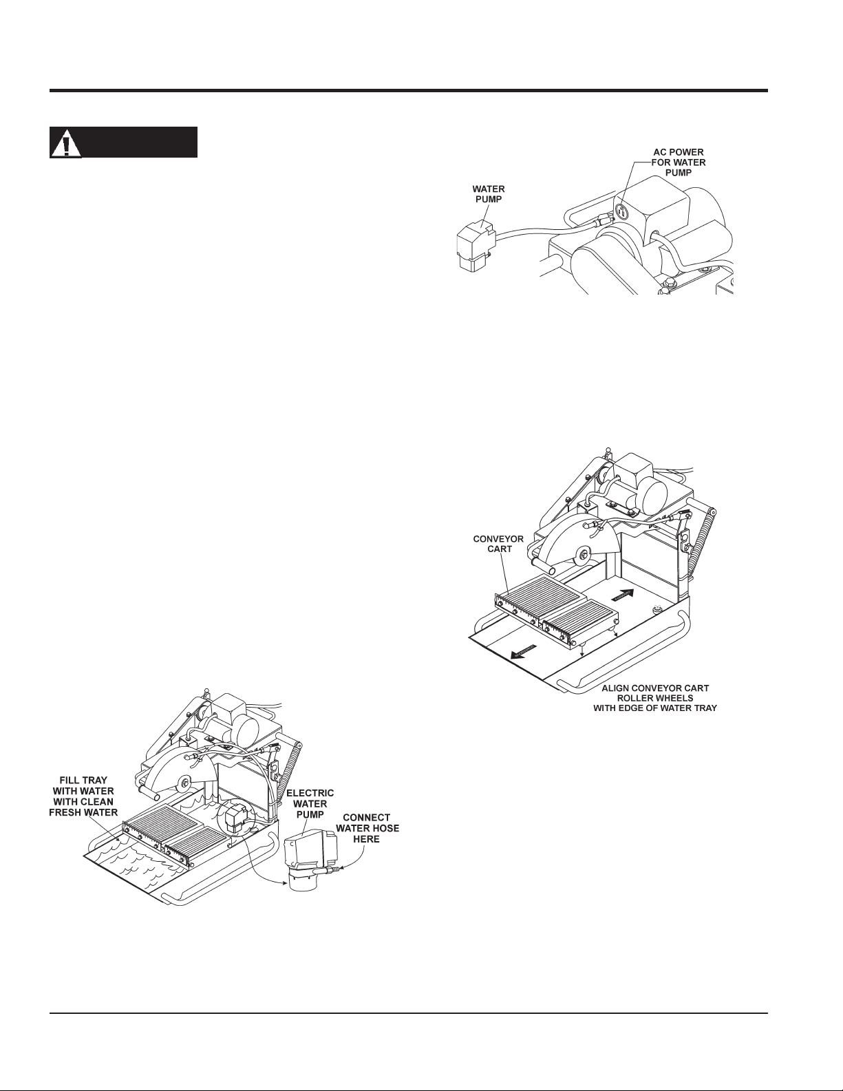
6. Insert the water pump
on the electric motor conduit box as shown in Figure 6.
WARNING
Whenever cleaning, adjusting or lubricating any part of the saw,
MAKE CERTAIN to place the power ON/OFF switch in the OFF
position and disconnect the plug from the power source.
Assembly (Electric Powered Saws Only)
1. Open the shipping container carefully, lift the saw by its carrying
handles and place it on a suitable table or platform. Make sure
the table or platform can support the weight of the saw. The
saw platform should be rigid and stationary so that it will not
move, sag, or sway due to the vibrations and movements of
the saw.
2. If using the MP1 series
attach stand to the under-side of the water tray. Follow the
instructions supplied with the support stand kit when attaching
it to the water tray.
3. Attach the clear plastic water hose (Figure 5) coming from the
blade guard to the water pump.
support stand kit
(P/N TRAK14SS),
CONVEYOR CART PLACEMENT
1. Place the conveyor cart across the water tray as shown in
Figure 7. Align the wheels of the cart with the outer edge of the
water tray. Push the cart back and forth, it should move freely in
both directions.
power plug
Figure 6. Water Pump Power Connection
into the outlet receptacle
4. Fill the water tray with
clean fresh water
intake must always be fully covered by water
keep the pump intake free of sludge, debris and other
materials that may accumulate in the tray.
5. Make certain that the water hose will not come in contact
with the blade or interfere with any moving parts. The best
location for the water pump/strainer is between the splash
shield and the rear of the water tray. This will prevent some
of the abrasive particles from flowing through the pump.
. The
water pump
. Also,
Figure 7. Conveyor Cart Placement
Figure 5. Water Tray/Water Pump
PAGE 20 — MP1 SERIES MASONRY SAWS — OPERATION AND PARTS MANUAL — REV. #1 (03/29/10)
Page 21
PRE-SETUP (ELECTRIC)
WARNING
4. Diamond Segment or Rim - Ensure there are no cracks,
Failure to thoroughly inspect the blade for
operational safety could result in damage
to the blades or the saw and may cause
serious injury to the user or others in the
operating area. Inspect the blade flanges
and shaft for damage before installing the
blade.
SAW BLADES
Diamond blades are recommended for you saw. Ask your
MULTIQUIP dealer about your specific cutting application.
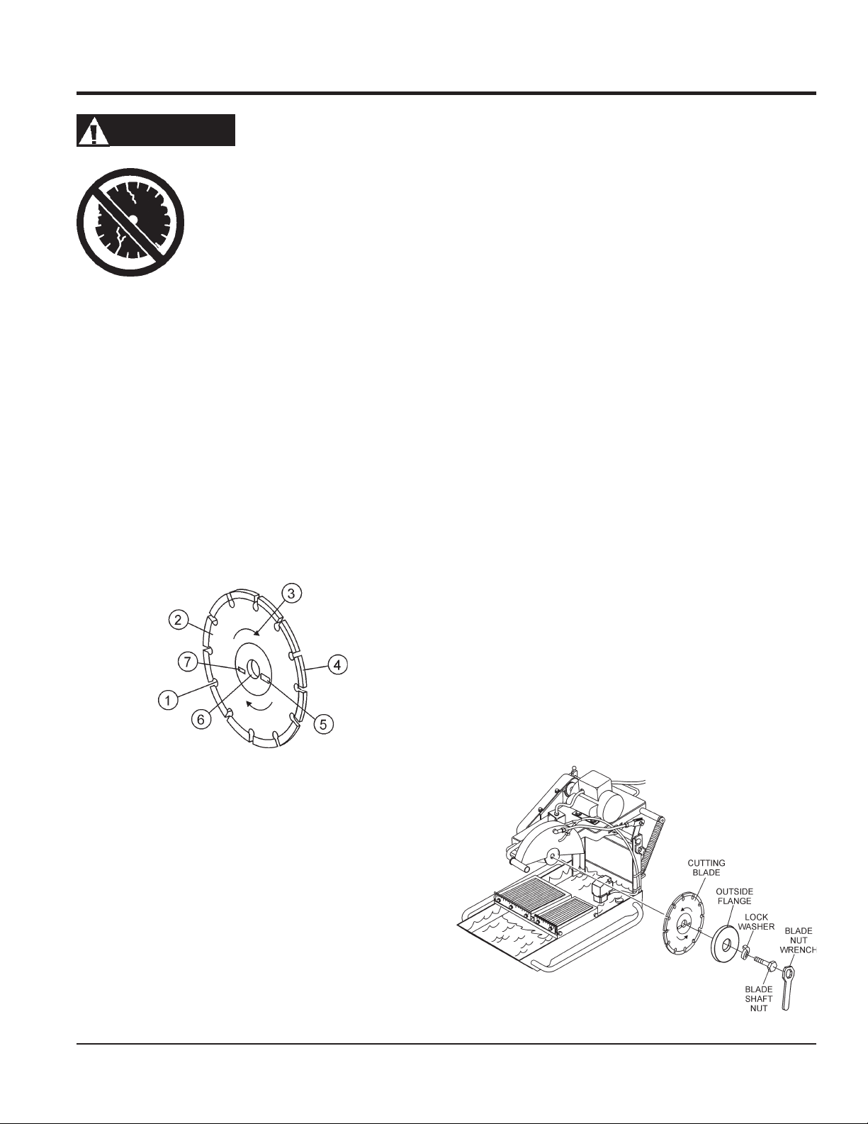
SAW BLADE DEFINITIONS (FIGURE 8)
1. Stress Relief Holes (Gullets) - Check the steel core for
cracks that may have propagated from the slots and/or
gullets. Cracks indicate extreme fatigue failure and if sawing
continues, catastrophic failure will occur.
5. Specifications - Ensure that the blade specifications, size,
6. Arbor Hole - It is essential that the arbor hole diameter
7. MAX RPM - This RPM reference is the maximum safe
BLADE INSTALLATION
dings, or missing portions of the diamond segment/rim. DO
use a blade that is missing a segment or a portion
NOT
of the rim.
cause damage to your saw or injury to the user or others in
the operating area.
and diameter properly match up to sawing operations.
Utilizing a blade not matched properly to the task may result
in poor performance and/or blade damage.
properly matches the blade, and that it is free from distortion.
Correct blade flanges (collars) must be used. The inside
face of the flanges must be clean and free of debris. An outof-round arbor condition will cause damage to the blade
and the saw.
operating speed for the blade selected. NEVER exceed the
max RPM on the diamond blade. Exceeding the maximum
RPM is dangerous and may cause poor performance and
may damage the blade.
Damaged and /or missing segments/rims may
1. Use the
2. Ensure the capacity of the blade guard matches the diameter
3. Using the blade nut wrench, remove the
Figure 8. Diamond Blade
2. Edge of the Steel Core - Check the diameter edge for
discoloration (blue oxidation) indicating an overheating
condition caused by insufficient cooling water/air.
Overheating of blades may lead to loss of core tension and/
or increase the possibility for blade failure. Make sure the
steel core's width is uniform about the rim of the blade, and
not succumbing to an "under-cutting" condition brought
about by highly abrasive material or improper under-cutting
core protection.
3. Directional Arrow - Ensure that the blade is oriented
properly on the blade shaft for sawing. Reference the
directional arrow on the blade and place it so the direction
of rotation "downcuts" with the turn of the shaft.
blade nut wrench
to install the cutting blade.
of your cutting blade.
(Figure 9) supplied with the saw
blade shaft nut
outside blade flange
blade flange arbor
blade shaft nut. Tighten securely. DO NOT over tighten.
Figure 9. Blade Placement
. Install the cutting blade onto the
. Re-install the outside blade flange and
inside
and
MP1 SERIES MASONRY SAWS — OPERATION AND PARTS MANUAL — REV. #1 (03/29/10) — PAGE 21
Page 22
PRE-SETUP (ELECTRIC)
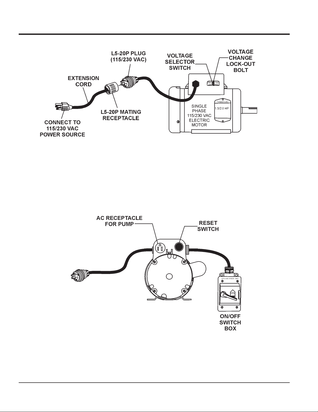
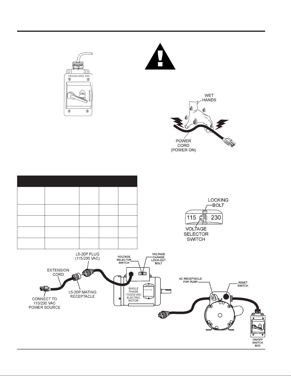
CONNECTING THE POWER (FIGURE 10)
1. Place the power ON/OFF switch (Figure 10) in the OFF
position (down).
CAUTIONCAUTION
CAUTION
CAUTIONCAUTION
NEVER use
connecting to a power source. Defective cables may cause
damage to the saw's electric motor or electrical shock.
Figure 10. Power ON/OFF Switch (OFF)
2. Connect an extension cord (Figure 13) of adequate current
carrying capacity to the power plug on the electric motor.
3. MAKE CERTAIN that the correct size extension cord is used.
Undersize wires will burn out motors. Use Table 4 to determine
the correct extension cord size.
ROTOM
EGATLOV
CAV
'05
GNOL
seziSdroCnoisnetxE.4ELBAT
'57
GNOL
4. This unit is shipped from the factory with the
switch
position of the switch from 115 VAC to 230 VAC, remove the
locking bolt and place the switch in the 230 VAC position. Re-
'001
GNOL
install the locking bolt to prevent accidently flipping the switch.
NEVER grab or touch a live power cord
(Figure 11) with wet hands , the possibility
exists of electrical shock, electrocution, and
even
death!
a damaged
Figure 11. Voltage Selector Switch
(Figure 12) in the 115 VAC position. To change the
or
worn
extension cable when
voltage selector
PH5.1 511
PH5.1
PH0.2 511
PH0.2
01.ON .ON
032 1.ON
032 21.ON .ON
4
1.ON
0
01
.ON
41
.ON
8
21
.ON
8
.ON
41
6.ON
21.ON
Figure 13. Extension Cord Connection
Figure 12. Voltage Selector Switch
PAGE 22 — MP1 SERIES MASONRY SAWS — OPERATION AND PARTS MANUAL — REV. #1 (03/29/10)
Page 23
PRE-SETUP (ELECTRIC)
CAUTIONCAUTION
CAUTION
CAUTIONCAUTION
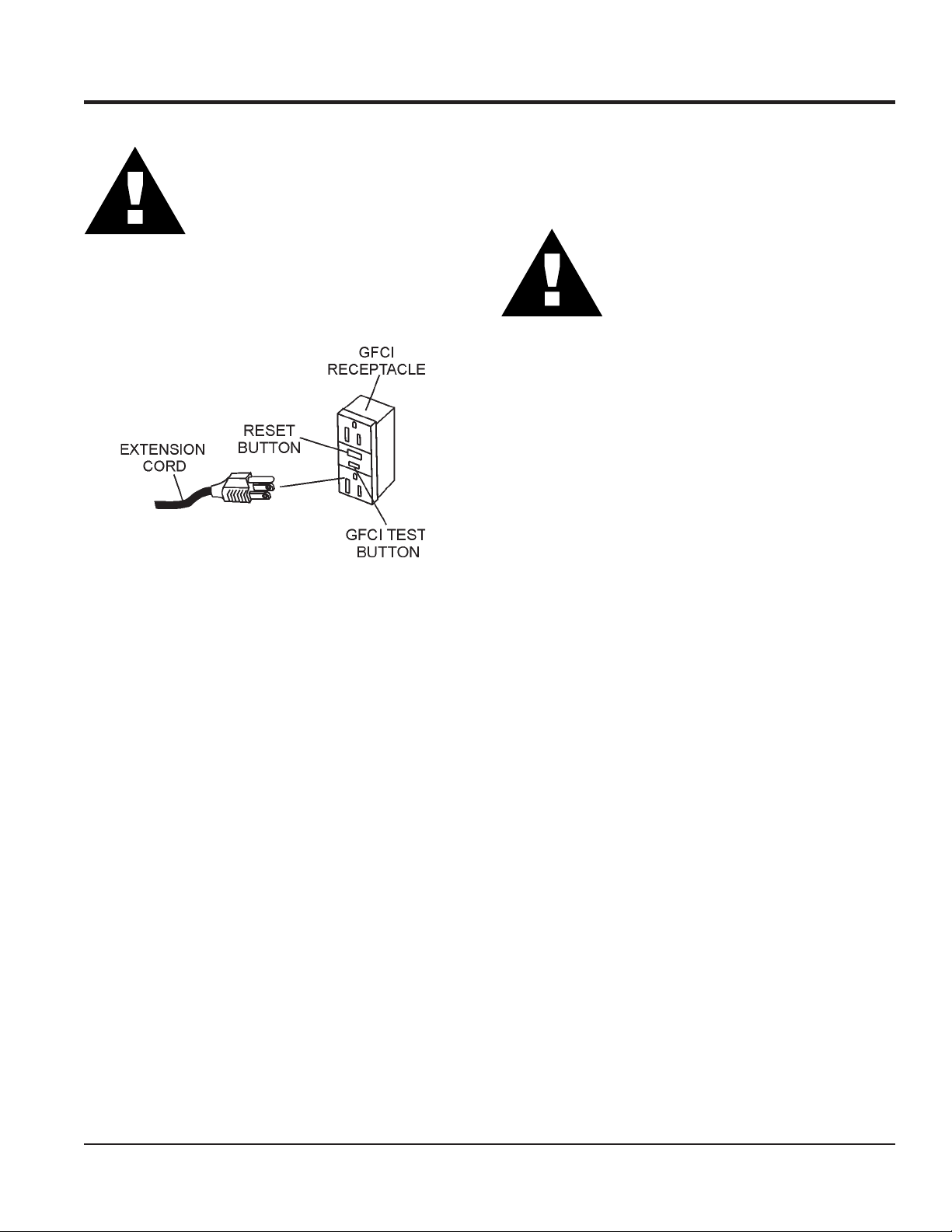
5. Plug the free end of the extension cord into an AC power
receptacle. Whenever possible use a GFCI receptacle
(Figure 14) to reduce the risk of electrical shock.
ALWAYS use a
extension cord and MAKE CERTAIN that the
motor is connected to a properly grounded
electric circuit. If possible use a ground fault
circuit interrupter to protect the operator from
possible
electric shock
grounded (3-wire
.
DRY CUTTING (ELECTRIC SAWS ONLY)
)
1. Un-plug the water pump power cord from the outlet
receptacle on the electric motor conduit box.
CAUTIONCAUTION
CAUTION
CAUTIONCAUTION
2. The MP1 masonry saw is now ready for
setup procedures for
complete.
NEVER
to a AC power source. Running the pump
dry
disconnect the pump's power cord when
dry cutting.
dry cut
will
electric models saws only
with the pump connected
damage
the pump. Always
dry cutting
. The pre-
is now
Figure 14. GFCI Receptacle
6. The MP1 masonry saw is now ready for
setup procedures for
complete.
electric models saws only
wet cutting
. The pre-
is now
MP1 SERIES MASONRY SAWS — OPERATION AND PARTS MANUAL — REV. #1 (03/29/10) — PAGE 23
Page 24
PRE-SETUP (GASOLINE)
PRE-SETUP
WARNING
Whenever cleaning, adjusting or lubricating any part of the saw,
MAKE CERTAIN to stop the engine and disconnect the spark
plug wire from the spark plug.
Assembly (Gasoline Powered Saws Only)
1. Remove the MP1 saw from its container and place it on a
suitable table or platform. Make sure the table or platform can
support the weight of the saw. The saw platform should be
rigid and stationary so that it will not move, sag, or sway due to
the vibrations and movements of the saw.
2. If using the MP1 series
attach stand to the under-side of the water tray. Follow the
instructions supplied with the support stand kit when attaching
it to the water tray.
3. The
gasoline powered
This pump operates by drawing power from the drive V-belts,
and has been adjusted and locked for wet cutting operation
when shipped from the factory.
support stand kit
saw uses a
(P/N TRAK14SS),
mechanical water
pump.
The MP1 gasoline model utilizes some of the same procedures
that are used for the MP1 electric models. Please reference pages
20 and 21 for the below referenced procedures:
■
Conveyor Cart Placement
■
Blade Selection and Inspection
■
Saw Blades
■
Blade Installation
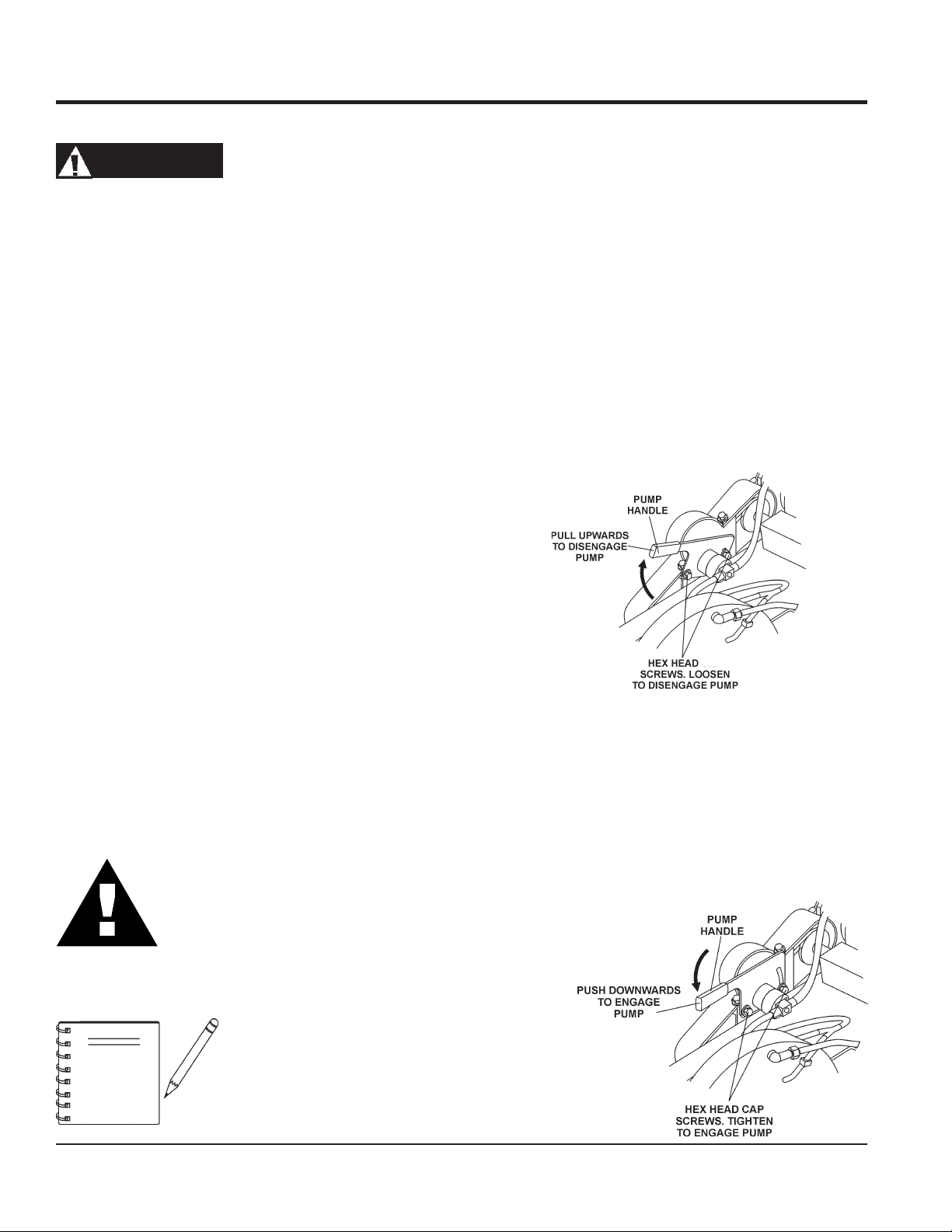
DRY CUTTING (GASOLINE ONLY)
To disconnect the
belts perform the following:
1. Loosen the 2 hex head cap screws (Figure 15) that secure
the pump mount bracket.
2.
Pull
3. Tighten the 2 hex head cap screws that secure the pump
mount bracket.
mechanical water pump
the pump handle
upward
from the drive V-
to disengage the pump.
4. Fill the water tray with clean fresh water. The
intake (strainer) must always be fully covered by water
to operate effectively
sludge, debris and other materials that may accumulate in
the tray.
5. Make certain that the water hose will not come in contact
with the blade or interfere with any moving parts. The best
location for the water pump/strainer is between the splash
shield and the rear of the water tray. This will prevent some
of the abrasive particles from flowing through the pump.
CAUTIONCAUTION
CAUTION
CAUTIONCAUTION
ALWAYS
tray in a manner that will allow the free
movement of the conveyor cart, and clearance
from the cutting blade and cutting action.
NOTE
. Also, keep the pump intake free of
position the
The mechanical water pump is
shipped from the factory for
cutting
strainer
applications.
water pump
in the water
wet
WET CUTTING (GASOLINE ONLY)
To connect the
perform the following:
1. Loosen the 2 hex head cap screws (Figure 16) that secure
the pump mount bracket.
2.
Push
3. Tighten the 2 hex head cap screws that secure the pump
mount bracket.
Figure 15. Pump Disengage
mechanical water pump
the pump handle
downward
to the drive V-belts
to engage the pump.
Figure 16. Pump Engage
PAGE 24 — MP1 SERIES MASONRY SAWS — OPERATION AND PARTS MANUAL — REV. #1 (03/29/10)
Page 25
BEFORE STARTING
1. Read safety instructions at the
beginning of manual.
2. Clean the saw, removing dirt and
dust, particularly the engine
cooling air inlet, carburetor and air
cleaner.
PRE-SETUP (GASOLINE)
3. Check the air filter for dirt and dust. If air filter is dirty, replace
air filter with a new one as required.
4. Check carburetor for external dirt and dust. Clean with dry
compressed air.
5. Check fastening nuts and bolts for tightness.
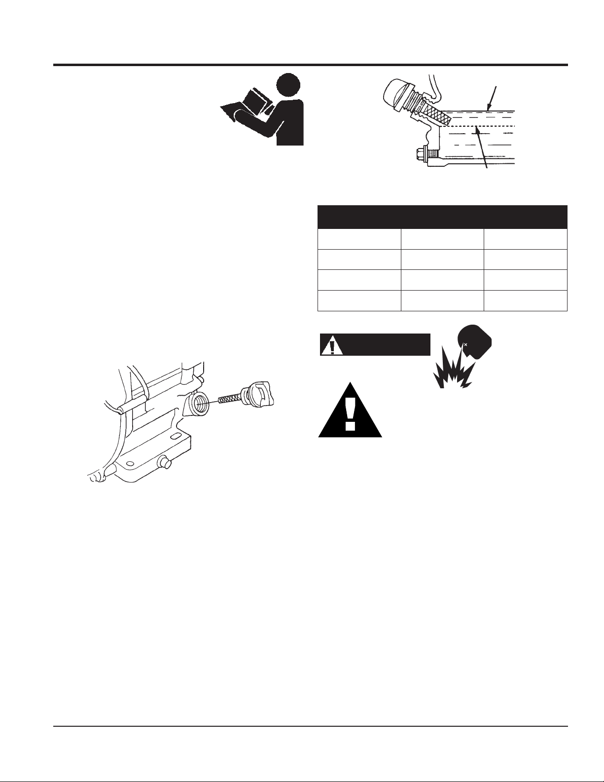
ENGINE OIL CHECK
1. To check the engine oil level, place the saw on a secure
level surface with the engine stopped.
2. Remove the filler dipstick from the engine oil filler hole
(Figure 17) and wipe clean.
DANGERDANGER
DANGER
DANGERDANGER
FUEL CHECK
Figure 18. Engine Oil Dipstick (Oil Level)
epyTliO.5elbaT
nosaeS erutarepmeT epyTliO
remmuS rehgiHroC°52 03-W01EAS
llaF/gnirpS C°01~C°52 02/03-W01EAS
retniW rewoLroC°0 01-W01EAS
Explosive Fuel
Motor fuels are highly flammable and can be
dangerous if mishandled. DO NOT smoke
while refueling. DO NOT attempt to refuel the
pump if the engine is
hot! or running
.
1. Remove the gasoline cap located on top of fuel tank.
Figure 17. Engine Oil Dipstick (Removal)
3. Insert and remove the dipstick without screwing it into the filler
neck. Check the oil level shown on the dipstick.
4. If the oil level is low (Figure 18), fill to the edge of the oil filler
hole with the recommended oil type (Table 5). Maximum oil
capacity is 0.63 quarts (0.60 liters)
2. Visually inspect to see if the fuel level is low. If fuel is low,
replenish with unleaded fuel.
3. When refueling, be sure to use a strainer for filtration. DO
NOT top-off fuel. Wipe up any spilled fuel
immediately!
MP1 SERIES MASONRY SAWS — OPERATION AND PARTS MANUAL — REV. #1 (03/29/10) — PAGE 25
Page 26
OPERATION (ELECTRIC)
START-UP ELECTRIC MOTOR
CAUTION
Read and fully understand this manual before
starting or attempting to operate the saw
Before starting the saw's electric motor make
sure that the
Inspection
been completed and understood. DO NOT
proceed until the above mentioned sections have been
completed.
ALWAYS use the
blades are being used. If dry cutting is required
water pump.
water feed system
Safety, General Information
and
Pre-setup
unless special
sections have
dry cut
disconnect
NEVER lift the blade guard while the blade
is rotating. The possibility exists of
bodily harm
.
contact with the rotating saw blade. Wait for
the blade to
,
blade guard.
WARNING
ALWAYS wear approved eye and hearing
protection before operating the saw.
WARNING
NEVER place hands or feet inside the belt
guard or blade guard while the engine is
running. ALWAYS shut the engine down before
performing any kind of maintenance
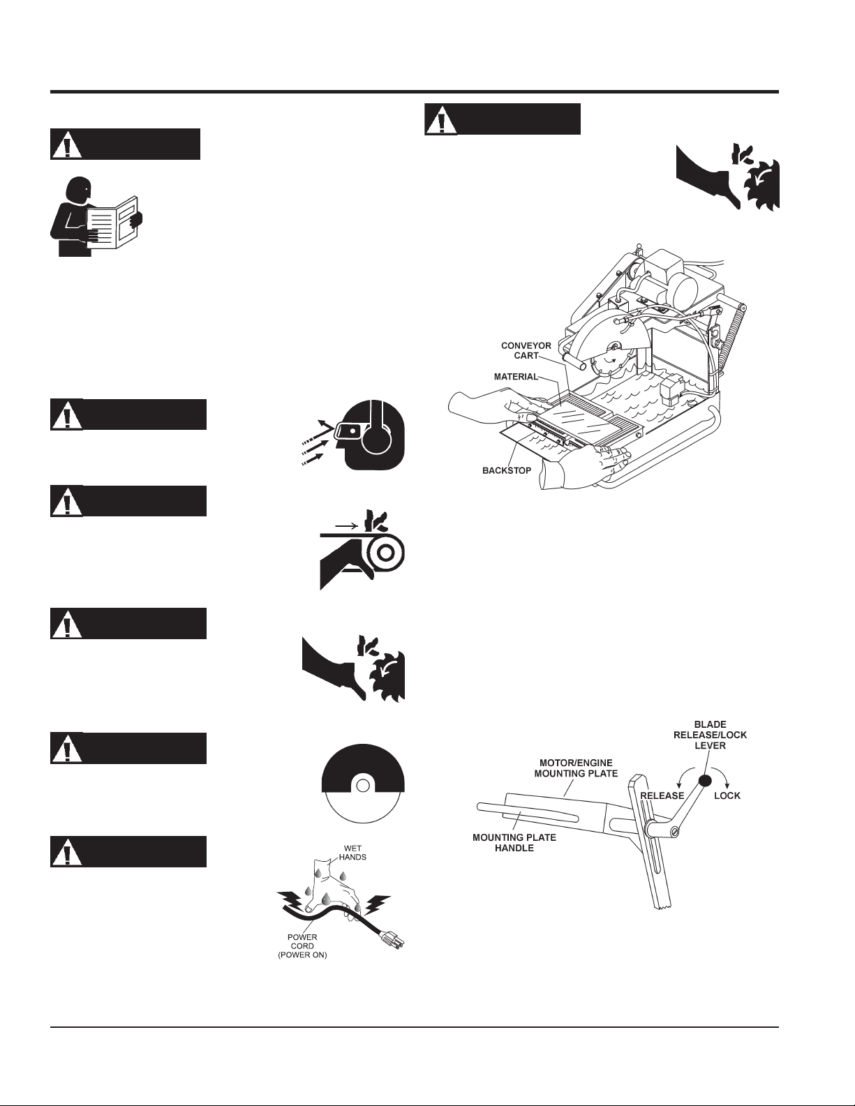
1. Place the material to be cut (Figure 19) on the conveyor
cart against the backstop.
WARNING
severe
if fingers or hands come in
stop rotating
Figure 19. Material Placement
before lifting the
WARNING
NEVER place hands and fingers near the
cutting blade. The possibility exist of severe
bodily harm if hands and fingers come in
contact with rotating saw blade.
WARNING
ALWAYS ensure that the cutting blade has
been mounted correctly and that it is raised
above the surface you are about to cut.
DANGER
NEVER touch a live power cord with
wet hands. The possibility exists of
electrical shock, electrocution which
could cause severe bodily harm even
death.
2. Place the
in the release position (pull back to release). When
releasing the lock, hold on to the mounting plate handle to
prevent the plate from rising rapidly, possibly causing the
saw to become unstable. Let the plate raise slowly.
Figure 20. Mounting Plate Release/Lock Lever
mounting plate release/lock lever
(Figure 20)
PAGE 26 — MP1 SERIES MASONRY SAWS — OPERATION AND PARTS MANUAL — REV. #1 (03/29/10)
Page 27
3. Adjust the cutting depth by pulling up or down on the
Cutting Head Handle
and is best utilized as a "
plate release/lock lever is released, the optimum cutting
action is attained by using the
rotate down onto the material to be cut. Simultaneously the
conveyor cart is moved slowly forward
material and cutting action.
A heavy-duty spring supports ergonomic return0t0-height
action of the cutting head assembly.
(Figure 21). This saw is designed,
Chop-Saw
". Once the mounting
Raise/Lower Handle
to advance the
to
OPERATION (ELECTRIC)
Figure 22. Power ON/OFF Switch (ON)
5. Push the
until the cut is complete. Move the cart back and remove
the cut pieces.
6. Avoid overloading the motor when cutting. However, the electric
motors are protected with a manual-reset thermal overload
switch that will turn the saw off if the motor is overheated. In the
event that the switch is tripped, turn the "ON/OFF" switch to
the "OFF" position and allow the motor to cool before
attempting to restart.
SHUTDOWN PROCEDURE
1. Place the power ON/OFF switch (Figure 23) in the OFF
position (down).
Figure 21. Cutting Head Handle
DANGER
ALWAYS
saw and be extremely aware of your body position - especially
your hands in relationship to the rotating blade. The possibility
exists of
in contact with the rotating saw blade.
be alert to the fact that there is a rotating blade on the
severe bodily harm even death
if your body comes
conveyor cart
Figure 23. Power ON/OFF Switch (OFF)
with the material, slowly and evenly
4. Turn the power ON/OFF switch (Figure 22) to the ON
position with the blade away from the material to be cut, the
cutting blade should begin to rotate. Before cutting
remember to follow all safety rules referenced in this
manual.
2. Wait for the cutting blade to stop rotating.
3. Disconnect the saw's AC power cord from the power source.
NEVER
unattended. This will prevent accidental starting.
4. Using a soft cloth, clean any excess debris or residue that
may have accumulated on the saw.
5. Store saw in a clean dry location where it will be out of the
reach of children.
leave the saw connected to a power source when
MP1 SERIES MASONRY SAWS — OPERATION AND PARTS MANUAL — REV. #1 (03/29/10) — PAGE 27
Page 28

OPERATION (GASOLINE)
START-UP GASOLINE ENGINE
WARNING
Read and fully understand this manual before
starting or attempting to operate the saw
Before starting the saw's electric motor make
sure that the
Inspection
been completed and understood. DO NOT proceed until the
above mentioned sections has been completed.
Safety, General Information
and
Pre-setup
sections have
.
,
WARNING
NEVER operate the saw in a confined area or
enclosed area structure that does not provide
free flow of air
ample
.
WARNING
The engine speed has been set at the factory.
Changing the governor speed could damage the
blade and/or the saw.
1. Place the
2. Place the
position.
fuel valve lever
Figure 24. Engine Fuel Valve Lever
Engine ON/OFF switch
(Figure 24) to the "ON" position.
(Figure 25) in the "ON"
ALWAYS use the
blades are being used. If dry cutting is required disconnect water
pump.
water feed system
unless special
dry cut
WARNING
ALWAYS wear approved eye and hearing
protection before operating the saw.
WARNING
NEVER place hands or feet inside the belt
guard or blade guard while the engine is
running. ALWAYS shut the engine down
before performing any kind of maintenance
service on the saw.
3. Place the
position.
WARNING
NEVER place hands and fingers near the
cutting blade. The possibility exist of severe
bodily harm if hands and fingers come in
contact with rotating saw blade.
Figure 25. Engine ON/OFF Switch
The CLOSED position of the
choke lever enriches the fuel
NOTE
Choke Lever
mixture for starting a COLD engine.
The OPEN position provides the
correct fuel mixture for normal
operation after starting, and for
restarting a warm engine.
(Figure 26) in the "
CLOSED
"
WARNING
ALWAYS ensure that the cutting blade has
been mounted correctly and that it is raised
above the surface you are about to saw.
Figure 26. Choke Lever
PAGE 28 — MP1 SERIES MASONRY SAWS — OPERATION AND PARTS MANUAL — REV. #1 (03/29/10)
Page 29
OPERATION (GASOLINE)
4. Rotate the
and
engine governor speed is factory set to ensure optimum
blade operating speeds.
5. Grasp the starter grip (Figure 28) and slowly pull it out. The
resistance becomes the hardest at a certain position, corresponding to the compression point. Pull the starter grip briskly
and smoothly for starting.
CAUTIONCAUTION
CAUTION
CAUTIONCAUTION
throttle lever
slow
for starting. All cutting is done at
Figure 27. Throttle Lever
DO NOT pull the starter rope all the way to
the end. DO NOT release the starter rope
after pulling. Allow it to rewind as soon as
possible.
(Figure 27) halfway between
full throttle
fast
. The
WARNING
ALWAYS
cut with the saw at less than full throttle could cause the blade to
bind or stop abruptly in the slab resulting in serious injury to the
operator or others in the area.
cut with the saw at FULL THROTTLE. Attempting to
DANGER
ALWAYS
saw and be extremely aware of your body position - especially
your hands in relationship to the rotating blade. The possibility
exists of
contact with the rotating saw blade.
10. Push the
11. Avoid overloading the engine when cutting. In the event that
STOPPING
be alert to the fact that there is a rotating blade on the
severe bodily harm even death
conveyor cart
until the cut is complete. Move the cart back and remove
the cut pieces.
the engine becomes overloaded, turn the engine ON/OFF
switch to the OFF position and allow the engine to
attempting to restart.
with the material, slowly and evenly
if your body comes in
cool
before
Figure 28. Starter Grip
6. If the engine has started, slowly return the choke lever
(Figure 26) to the
started repeat steps 1 through 5.
7. Before the saw is placed into operation, run the engine for
several minutes. Check for fuel leaks, and noises that would
associate with a loose guards and/or covers.
8. Gradually move the engine throttle lever toward the
position. (
9. Squeeze the water pump
water begins to flow through the
water lines. If the pump is working
correctly, the cutting blade should be
covered with a steady water mist.
This will keep the blade cool.
"OPEN"
All cutting should be done at full
position. If the engine has not
fast
throttle
priming bulb
(Figure 29)until
1. Set the engine throttle lever to
2. Turn the engine ON/OFF switch to the "OFF" position.
3. Place the fuel valve lever in the
4. Let the engine cool.
5. Using a soft cloth, clean any excess debris or residue that
).
6. Store saw in a clean dry location where it will be out of the
idle for 3-5 minutes.
may have accumulated on the saw.
reach of children.
WARNING
Engine components can generate extreme heat.
To prevent burns, DO NOT touch these areas
while the engine is running or immediately after
operations. NEVER operate the engine with
heat shields or heat guards removed.
slow
speed and let the engine
closed
position.
Figure 29. Priming Bulb
MP1 SERIES MASONRY SAWS — OPERATION AND PARTS MANUAL — REV. #1 (03/29/10) — PAGE 29
Page 30
MAINTENANCE (SAW)
MAINTENANCE
A good preventive maintenance program of regular inspection
and care will increase life and improve the performance of the
saw and cutting blades.
B. Gasoline Powered Saws - To adjust belt tension, loosen the
four (4) jackshaft mounting bolts and remove the belt guard.
Screw the adjusting bolt back to increase the tension. Proper
belt tension is 4-5 lbs. of force with approximately 1/8" of belt
deflection measured at a point halfway between the pulleys.
WARNING
Whenever cleaning, adjusting, or lubricating any part of the saw,
MAKE CERTAIN to do the following:
Electric Powered Saws
■
Place power ON/OFF switch to the OFF position.
■
Disconnect power cord from AC source.
■
NEVER attempt to check the V-belt with the engine running.
Severe bodily injury can occur.
Gasoline Powered Saws
■
Turn the engine switch to the "OFF" position, disconnect the
spark plug wire and secure it away from the spark plug.
■
NEVER attempt to check the V-belt with the engine running.
Severe bodily injury can occur.
BASIC MAINTENANCE
1. Tighten loose nuts or screws and replace any cracked or
broken parts.
2. Clean the machine frequently. Remove the belt guard and
clean the pulleys. The belts and pulleys will wear rapidly if
excessive dust builds up.
3. Clean the sludge that accumulates on the bottom of the water
tray at least once a day and refill with clean water. It may be
necessary to clean the tray out twice a day in heavy cutting.
The sludge is abrasive and will shorten the life of the water
pump and blades.
4. After each day's use, clean the sludge from the bottom of the
tray and run clean water through the water pump and water
hoses. This extends pump and blade life.
5. Lubricate the blade adjustment rod after every eight (8) hours
of use.
6. Check the spindle bolt for tightness periodically.
7. Keep the drive belts tight. It is very important to replace worn
belts as soon as possible.
A. Electric Powered Saws - To adjust belt tension, loosen
the four (4) motor mounting bolts and remove the belt
guard. Tighten the two (2) adjusting nuts on the back of
the motor plate to increase the tension. Proper belt
tension is 4-5 lbs. of force with approximately 3/16" of
belt deflection measured at a point midway between
the pulleys. Tighten the motor mounting bolts and reattach the belt guard.
NOTE
Tighten the jackshaft bearing mounting bolts (4) that are located
under the weldment. Next, loosen the (4) engine mounting
bolts and remove the belt guard. Tighten the (2) nuts on the
engine tensioning bolts that are at the rear of the weldment.
Proper belt tension is 4-5 lbs. of force with approximately 1/8"
of belt deflection measured at a point halfway between the
pulleys. Tighten the engine mounting bolts.
Pull on the recoil to make certain everything moves smoothly
and freely. If the recoil pulls hard, the belts are probably adjusted
a little
continuing. Attach the belt guards to the saw. Make certain
that the guards do not come in contact with the belts or each
other. There are slots in the guard mounting plates so
adjustments can be made if necessary. Tighten all bolts on the
guards and their mounts.
8. MAKE CERTAIN that the cutting head is aligned properly.
Misalignment can adversely affect blade life.
9. The blade flanges must have a diameter of 4". Undersize
flanges will reduce blade life and cause breakage. Therefore,
they should be replace at once.
10. Cutting blades must fit the arbor snugly. This is very important
with diamond blades as pounding will occur and serious blade
damage can result. If the arbor shoulder of the inner blade
flange is grooved from blade slippage, the flange must be
replaced.
11. Inspect the conveyor cart periodically. Replace the wood insert
and wheels when necessary.
12. Lubricate spindle bearings after each day's operation. When
dry cutting, grease bearings several times during the day's
operation to protect them from the dust.
too tight
. Belt tensions should be readjusted before
It is very important that the jackshaft
and blade arbor
to each other. This can be
accomplished by using the
adjusting bolt located on the
engine mounting plate to help keep
the jackshaft from cocking.
remain parallel
PAGE 30 — MP1 SERIES MASONRY SAWS — OPERATION AND PARTS MANUAL — REV. #1 (03/29/10)
Page 31

MAINTENANCE (SAW)
13. Replace the spindle bearings as soon as they begin to make
any strange noises. Worn bearings can destroy blades very
quickly.
14. Grease pivot bearings periodically.
CUTTING HEAD ALIGNMENT (BLADE)
Make certain the
can adversely affect blade life. The motor/engine plate is slotted
so adjustment to the blade can be made as needed. The left side
has vertical slots, and the right side has horizontal slots. To adjust
the cutting head either vertical or horizontally perform the
following:
VERTICAL ADJUSTMENT
Remove the motor or engine from the mounting plate. Loosen
the pivot bearing bolts (2) on the left side of the mounting plate.
Move the pivot bearing to the extreme top of the slots in the
mounting plate. Thread a 3/8-16 bolt (adjusting bolt) down
through the hole in the top of the mounting plate. Tighten the bolt
against the bearing.
This will raise the mounting plate. Continue to tighten the bolt
until the blade is perpendicular to the conveyor cart. Tighten the
pivot bearing bolts. Remove the adjusting bolt and reassemble.
cutting head
is aligned properly. Misalignment
CAUTION:CAUTION:
CAUTION:
CAUTION:CAUTION:
from the pivot shaft, MAKE CERTAIN the motor/engine plate is
supported to prevent the cutting head from dropping.
CUTTING HEAD REMOVAL
To remove the cutting head (Figure 31) perform the following:
1. Loosen the knobs (2) located on each side of uprights.
2. Slide the hooks (2) up and away from the pivot shaft.
3. Remove the handle lock that fastens the blade height adjusting
arm to the motor/engine plate. This is accomplished by simply
removing the cotter pin.
4. Disconnect the spring from the pivot shaft by raising the cutting
head until the tension is relieved from the spring.
5. To reassemble the cutting head, reverse these steps.
When loosening the handle lock, hold onto
the front of the motor/engine plate handle to
prevent the plate from raising rapidly, possible
causing the saw to become unstable. Let the
plate raise slowly. When removing the spring
HORIZONTAL ADJUSTMENT
Loosen the pivot bearings (2) on the right-side of the mounting
plate. Slide the pivot bearing forward or backwards as needed,
until the blade is parallel with the conveyor cart. Tighten the pivot
bearing bolts.
BEARING LUBRICATION CARE
There are two (2) grease points (Figure 30) for the MP1
model saw. Use only Premium Lithium 12 based Grease,
conforming to NLG1 Grade #2 consistency. Grease
gasoline
daily
.
Figure 31. Cutting Head Removal
Figure 30. Zerk Fittings (Lubrication)
MP1 SERIES MASONRY SAWS — OPERATION AND PARTS MANUAL — REV. #1 (03/29/10) — PAGE 31
Page 32

MP1 — MAINTENANCE (ENGINE)
ENGINE MAINTENANCE
Perform engine maintenance procedures as referenced by
Table 6 below:
eludehcSecnanetniaMenignE.6elbaT
TSRIF
)3(NOITPIRCSEDNOITAREPOEROFEB
KCEHCX
liOenignE
EGNAHCX
KCEHCX
renaelCriA
EGNAHC)1(X
stloB&stuNllA
gulPkrapS
sniFgnilooCKCEHCX
retserrAkrapSNAELC X
knaTleuFNAELC X
fInethgit-eR
yrasseceN
NAELC-KCEHCX
ECALPER X
X
HTNOM
RO
.SRH01
YREVE
SHTNOM3
RO
.SRH52
YREVE
SHTNOM6
RO
.SRH05
YREVE
RAEY
RO
01
.SRH0
YREVE
SRAEY2
RO
.SRH002
retliFleuFKCEHC X
DA-KCEHC )2(X
nidesunehwylt
resebdluohssmetiesehT)2(
serudecorpecivresroflaunaMpohsADNOHehtotrefeR.tneiciforp
reporpenimretedotnoitarepofosruohgol,esulaicremmocroF)3(
.slavretniecnanetniam
yllacinahcemeradnaslootreporpehtevahuoysselnu,relaedcivresruoyybdeciv
NOTE
deepSeldITSUJ
ecnaraelCevlaVTSUJDA-KCEHC )2(X
senilleuFKCEHC )2()yrassecenfiecalper(sraey2yrevE
neuqerferomecivreS)1( YTSUD .saera
Reference manufacturer engine
manual for specific servicing
instructions.
PAGE 32 — MP1 SERIES MASONRY SAWS — OPERATION AND PARTS MANUAL — REV. #1 (03/29/10)
Page 33

MP1 — MAINTENANCE (ENGINE)
MAINTENANCE
Perform the engine maintenance procedures as indicated below:
DAILY
■
Thoroughly remove dirt and oil from the engine and control
area. Clean or replace the air cleaner elements as necessary.
Check and retighten all fasteners as necessary. Check the
spring box and bellows for oil leaks. Repair or replace as
needed.
WEEKLY
■
Remove the fuel filter cap and clean the inside of the fuel
tank.
■
Remove or clean the filter at the bottom of the tank.
■
Remove and clean the spark plug (Figure 32), then adjust
the spark gap to 0.028 ~0.031 inch (0.6~0.7 mm). This unit
has electronic ignition, which requires no adjustments.
DANGER:DANGER:
DANGER:
DANGER:DANGER:
ENGINE AIR CLEANER
1. Remove the air cleaner cover and foam filter element as
2. Tap the paper filter element (Figure 34) several times on a
3. Clean foam element in warm, soapy water or nonflammable
DO NOT use gasoline as a cleaning solvent,
because that would create a risk of fire or
explosion.
shown in Figure 34.
hard surface to remove dirt, or blow compressed air [not
exceeding 30 psi (207 kPa, 2.1 kgf/cm
element from the air cleaner case side.
Brushing will force dirt into the fibers. Replace the paper filter
element if it is excessively dirty.
solvent. Rinse and dry thoroughly. Dip the element in clean
engine oil and completely squeeze out the excess oil from the
element before installing.
2
)] through the filter
NEVER
brush off dirt.
Figure 32. Spark Plug Gap
ENGINE OIL
warm
1. Drain the engine oil when the oil is
Figure 33.
2. Remove the oil drain bolt and sealing washer and allow
the oil to drain into a suitable container.
3. Replace engine oil with recommended type oil as listed
in Table 5. Engine oil capacityis 0.63 quarts (0.60 liters).
DO NOT overfill.
4. Install drain bolt with sealing washer and tighten securely.
as shown in
Figure 34. Engine Air Cleaner
Figure 33. Engine Oil (Draining)
MP1 SERIES MASONRY SAWS — OPERATION AND PARTS MANUAL — REV. #1 (03/29/10) — PAGE 33
Page 34

WIRING DIAGRAM - ELECTRIC MOTOR
Figure 34. Electric Motor Wiring Diagram
PAGE 34 — MP1 SERIES MASONRY SAWS — OPERATION AND PARTS MANUAL — REV. #1 (03/29/10)
Page 35

NOTES
MP1 SERIES MASONRY SAWS — OPERATION AND PARTS MANUAL — REV. #1 (03/29/10) — PAGE 35
Page 36

Symptom Possible Problem Solution
Blade slows or stops cutting, still
remains on blade
Blade does not cut straight and/
or true.
Blade discoloring, crackling and/or
wearing excessively.
TROUBLESHOOTING - BLADE
Table 7. Blade Troubleshooting
Consult dealer or Multiquip for correct blade. Try cutting
Blade too hard for the material being cut?
Engine torque diminished because of loose
V-belt?
Insufficient engine power? Check throttle setting. Check engine horsepower.
Improper direction of rotation?
Blade is slipping onto the blade shaft?
Blade being used on misaligned saw? Check blade shaft bearings and alignment integrity.
Blade is excessively hard for the material
being cut?
Blade improperly mounted on arbor
shoulders and flanges?
Excessive force applied to blade while
cutting?
Blade is too hard for material being cut?
Blade improperly mounted on arbor
shoulders and flanges?
Blade not receiving enough cooling water or
air?
Arbor hole out of round? Ensure blade is properly affixed on the blade shaft.
Incorrect blade chosen for material being
cut?
Excessive force applied to blade while
cutting?
very soft material (sandstone, silica brick, cinder block)
to “redress” the blade.
Tighten and/or replace V-belt.
Check that the blade is properly oriented and rotational
arrow points in a “down-cutting” direction.
Check that the blade and flange pin are properly
installed on the blade shaft.
Check specification of the blade with the material being
cut. Consult dealer or Multiquip for information.
Ensure blade is properly affixed on the blade shaft.
DO NOT force the blade in the cut. Apply a slow and
steady pace when sawing.
Consult dealer or Multiquip for correct blade. Try cutting
very soft material (sandstone, silica brick, cinder block)
to “redress” the blade.
Ensure blade is properly affixed on the blade shaft.
Ensure proper flow and volume of water is provided
for wet cutting blades. Ensure sufficient cooling air is
circulated about a dry cutting blade.
Check specification of the blade with the material being
cut. Consult dealer or Multiquip for information.
DO NOT force the blade in the cut. Apply a slow and
steady pace when sawing.
PAGE 36 — MP1 SERIES MASONRY SAWS — OPERATION AND PARTS MANUAL — REV. #1 (03/29/10)
Page 37

TROUBLESHOOTING - ELECTRIC MOTOR
)ROTOMCIRTCELE(GNITOOHSELBUORT.8ELBAT
NOTPMYSMELBORPELBISSOPNOITULOS
?nideggulpdrocrewoP detcennocylreporpsiwa
?drocrewopevitcefeD.drocrewopecalpeR
nehwnurtonseodwaS
.nohctiwssirewop
?snoitcennoclacirtceleesooL aybdekcehcmetsyslacirtceleevaH
?rotomevitcefeD .yrassecenfiecalperdnarotomkcehC
netxe/drocrewoP foelbacnoisnetxe/drocrewopaesU
elttilecnamrofrepwasrooP
.rewop
astcerrocnI otsdnopserrochcihwedalbwasaesU
)tuostucrewop(spotsrotoM
?edalbw
?tneiciffusnisiecruosrewoP ebtsumti
?evitcefedwasnohctiwsrewopniaM .yrassecenf
?gnolootelbacnois
?deepsdetartanurrotomseoD .yrassecenfiecalpe
?gnittucelihwdetrexehcumooT .gnittucnehwerusserpsseltrexE
stahtkcehC
.ecruosrewopaot
ihctiwsecalperdnakcehC
ifilauq
rdnarotomkcehC
.naicirtceledesnecilde
.4elbaTeeS.htgneldetar
ucriC.tiucriclacirtcelekcehC
.muminimspma02gniylppusfoelbac
.tucgnieblairetameht
?metsyslacirtceleevitcefeD aybdekcehcmets
MP1 SERIES MASONRY SAWS — OPERATION AND PARTS MANUAL — REV. #1 (03/29/10) — PAGE 37
yslacirtceleevaH
.naicirtceledesnecildeifilauq
Page 38

TROUBLESHOOTING - GASOLINE ENGINE
MOTPMYS MELBORPELBISSOP NOITULOS
tratsottluciffiD
?egdirbgniebgulpnoitingI .metsysnoitingikcehC
GNITOOHSELBUORTENIGNE.9ELBAT
.)elbacnoisnethgihta
rewoP(.etingitonlliw TON
noisserpmoc(setingi )lamron .
noisserpmoc(setingi wol .)
yrotcafsitastonnoitarepO
gulpkrapstubelbaliavasileuF
elbaliavarewoP(.etingitonlliw
?srotalusni
gulpkrapstubelbaliavasileuF
.)elbacnoisnethgihtaelbaliava
?stisoped
gulpkrapsdnaelbaliavasileuF
gulpkrapsdnaelbaliavasileuF
?etauqedani
?)tsud
?nrowrednilyC .rednilycecalpeR
?noitingitatisopednobraC .noitingiecalperronaelC
evitcefedoteudtiucrictrohS
?pagkrapsreporpmI .pagtcerrocehtotpaggulpkrapsteS
?hctiwspotstatiucrictrohS .evitcefedfihctiwspotsecalpeR.tiucrichctiwspotskcehC
?evitcefedliocnoitingI .liocnoitingiecalpeR
nobrachtiwdeggolcrelffuM
siytilauqleufdexiM
,retaw(etauqedaniesunileuF
?deggolcrenaelCriA .renaelcriaecalperronaelC
?teksagdaehrednilycevitcefeD .teksagdaehecalperrostlobdaehrednilycnethgiT
?esoolgulpkrapS .gulpkrapsnehgiT
.srotalusniecalpeR
.relffumecalperronaelC
.erutximliootleufkcehC
.leufhserfhtiwecalperdnametysleufhsulF
?deggolcrenaelcriA .renaelcriaecalperronaelC
elbaliavarewophguonetoN
-ssimon,lamronnoisserpmoc(
.)gnirif
elbaliavarewophguonetoN
-ssim,lamronnoisserpmoc(
.)gnirif
.staehrevoenignE
?enilleufniriA .enilleufmorf)riaevomer(deelB
?reporpmirebmahc
taolfrotaerubracnilevelleuF
?rednilycnistisopednobraC rednilycecalperronaelC
?evitcefedliocnoitingI .leufhserfhtiwecalperdnametysleufhsulF
?strohsnetfogulpnoitingI .noitinginaelc,seriwnoitingiecalpeR
,retaw(etauqedaniesunileuF
?)tsud
ninoitsopednobracevissecxE
?rebmahcnoitsubmoc
htiwdeggolcrelffumrotsuahxE
.nobrac
?tcerrocnieulavtaehgulpkrapS .gulpkrapsepyttcerrochtiwgulpkrapsecalpeR
taolfrotaerubractsujdA
.leufhserfhtiwecalperdnametysleufhsulF
.esacknarcecalperronaelC
.relffumecalperronaelC
PAGE 38 — MP1 SERIES MASONRY SAWS — OPERATION AND PARTS MANUAL — REV. #1 (03/29/10)
Page 39

TROUBLESHOOTING - GASOLINE ENGINE
MOTPMYS MELBORPELBISSOP NOITULOS
yrotcafsitastonnoitarepO
?reporpmitnemtsujdaronrevoG .reveltcerrocotronrevogtsujdA
)deunitnoC(GNITOOHSELBUORTENIGNE.7ELBAT
.setautculfdeepslanoitatoR
?citarrewolfleuF .enilleufkcehC
gnikrowtonretratslioceR
.ylreporp
?evitcefedgnirpsronrevoG .noitingiecalperronaelC
?trapgnitatornitsuD .ylbmessaretratsliocernaelC
?eruliafgnirpsgnirpS .gnirpslairpsecalpeR
MP1 SERIES MASONRY SAWS — OPERATION AND PARTS MANUAL — REV. #1 (03/29/10) — PAGE 39
Page 40

EXPLANATION OF CODE IN REMARKS COLUMN
The following section explains the different symbols and
remarks used in the Parts section of this manual. Use the
help numbers found on the back page of the manual if there
are any questions.
NOTICE
The contents and part numbers listed in the parts
section are subject to change without notice. Multiquip
does not guarantee the availability of the parts listed.
SAMPLE PARTS LIST
NO. PART NO. PART NAME QTY. REMARKS
1 12345 BOLT ......................1 .....INCLUDES ITEMS W/%
2% WASHER, 1/4 IN. ...........NOT SOLD SEPARATELY
2% 12347 WASHER, 3/8 IN. ...1 .....MQ-45T ONLY
3 12348 HOSE ..................A/R ...MAKE LOCALLY
4 12349 BEARING ..............1 .....S/N 2345B AND ABOVE
NO. Column
Unique Symbols — All items with same unique
symbol
QTY. Column
Numbers Used — Item quantity can be indicated by a
number, a blank entry, or A/R.
A/R (As Required) is generally used for hoses or other
parts that are sold in bulk and cut to length.
A blank entry generally indicates that the item is not sold
separately. Other entries will be clarified in the “Remarks”
Column.
REMARKS Column
Some of the most common notes found in the “Remarks”
Column are listed below. Other additional notes needed
to describe the item can also be shown.
Assembly/Kit — All items on the parts list with the
same unique symbol will be included when this item is
purchased.
Indicated by:
“INCLUDES ITEMS W/(unique symbol)”
(@, #, +, %, or >) in the number column belong to the
same assembly or kit, which is indicated by a note in the
“Remarks” column.
Duplicate Item Numbers — Duplicate numbers indicate
multiple part numbers, which are in effect for the same
general item, such as different size saw blade guards in
use or a part that has been updated on newer versions
of the same machine.
NOTICE
When ordering a part that has more than one item
number listed, check the remarks column for help in
determining the proper part to order.
PART NO. Column
Numbers Used — Part numbers can be indicated by a
number, a blank entry, or TBD.
TBD (To Be Determined) is generally used to show a
part that has not been assigned a formal part number
at the time of publication.
A blank entry generally indicates that the item is not sold
separately or is not sold by Multiquip. Other entries will
be clarified in the “Remarks” Column.
Serial Number Break — Used to list an effective serial
number range where a particular part is used.
Indicated by:
“S/N XXXXX AND BELOW”
“S/N XXXX AND ABOVE”
“S/N XXXX TO S/N XXX”
Specific Model Number Use — Indicates that the part
is used only with the specific model number or model
number variant listed. It can also be used to show a
part is NOT used on a specific model or model number
variant.
Indicated by:
“XXXXX ONLY”
“NOT USED ON XXXX”
“Make/Obtain Locally” — Indicates that the part can
be purchased at any hardware shop or made out of
available items. Examples include battery cables, shims,
and certain washers and nuts.
“Not Sold Separately” — Indicates that an item cannot
be purchased as a separate item and is either part of an
assembly/kit that can be purchased, or is not available
for sale through Multiquip.
PAGE 40 — MP1 SERIES MASONRY SAWS — OPERATION AND PARTS MANUAL — REV. #1 (03/29/10)
Page 41

SUGGESTED SPARE PARTS
MP1 MASONRY SAW 1 TO 3 UNITS
Electric Motor Models
Qty. P/N Description
2 ............ 15503 .................... KNOB, COMFORT GRIP
2 ............ 10136 .................... WASHER, FLAT 3/8
2 ............ 0166 A .................. WASHER, LOCK 3/8
1 ............ 23783-001 ............ WRENCH, HEX 3/4
4 ............ 521003 .................. V-BELT, ELECTRIC MOTOR AX-34
1 ............ 23843-001 ............ WATER PUMP, ELECTRIC MOTOR
4 FT. ...... 23867-002 ............ VINYL WATER TUBING
1 ............ 24301-501 ............ CONVEYOR CART
2 ............ 29713-001 ............ BLADE SHAFT BEARING
2 ............ 8136 ...................... BLADE SCREW
2 ............ 5054 A .................. WASHER, LOCK
2 ............ 23832-001 ............ OUTER BLADE FLANGE
2 ............ 23846-001 ............ OUTER BLADE FLANGE
2 ............ 29719-001 ............ HANDLE LOCK
MP1 MASONRY SAW 1 TO 3 UNITS
Gasoline Engine Model
Qty. P/N Description
2 ............ 15503 .................... KNOB, COMFORT GRIP
2 ............ 28321-001 ............ BLADE SHAFT BEARING
2 ............ 8136 ...................... BLADE SCREW
2 ............ 5054 A .................. WASHER, LOCK
2 ............ 10136 .................... WASHER, FLAT 3/8
2 ............ 0166 A .................. WASHER, LOCK 3/8
1 ............ 23783-001 ............ WRENCH, HEX 3/4
4 ............ 16779-012 ............ V-BELT, DRIVE, 3VX250
4 ............ 16779-006 ............ V-BELT, JACK SHAFT 3VX300
1 ............ 25807-502 ............ WATER PUMP KIT
4 FT. ...... 23867-002 ............ VINYL WATER TUBING
1 ............ 25685-001 ............ STRAINER
1 ............ 24301-501 ............ CONVEYOR CART
2 ............ 23832-001 ............ OUTER BLADE FLANGE
2 ............ 23846-001 ............ OUTER BLADE FLANGE
2 ............ 29719-001 ............ HANDLE LOCK
3 ............ 17210ZE1505 ....... ELEMENT, AIR CLEANER
3 ............ 9807956846 .......... SPARK PLUG
1 ............ 17620ZH7023 ....... CAP, FUEL FILLER
1 ............ 28462ZH8003 ....... ROPE, RECOIL STARTER
MP1 SERIES MASONRY SAWS — OPERATION AND PARTS MANUAL — REV. #1 (03/29/10) — PAGE 41
Page 42

NAMEPLATE AND DECALS
NAME PLATE AND DECALS
PAGE 42 — MP1 SERIES MASONRY SAWS — OPERATION AND PARTS MANUAL — REV. #1 (03/29/10)
Page 43

NAME PLATE AND DECALS
NAMEPLATE AND DECALS
NO. PART NO. PART NAME QTY. REMARKS
1 25249-001 DECAL, KEEP HANDS CLEAR 1
2 25678 DECAL, CCW ROTATION 1
3 25139-001 DECAL, EXTENSION CORD SIZE ................ 1 ..........ELECTRIC MODELS ONLY
4 38213 DECAL, MULTIQUIP BLACK 1
5 13118 DECAL, POWDER COATED 1
6 38240 DECAL, MP1 2
7 25215-001 DECAL, ELECTRIC CORD WARNING............1 .......... ELECTRIC MODELS ONLY
8 PLATE, MODEL/SERIAL NUMBER ................1 .......... CONTACT PARTS DEPT.
9 25349-001 DECAL, GUARD WARNING 1
10 38239 DECAL, MULTIQUIP 1
11 20525 DECAL, PROP 65 1
12 22122-001 DECAL, SERIOUS INJURY WARNING 1
MP1 SERIES MASONRY SAWS — OPERATION AND PARTS MANUAL — REV. #1 (03/29/10) — PAGE 43
Page 44

TRAY ASSY.
TRAY ASSY.
PAGE 44 — MP1 SERIES MASONRY SAWS — OPERATION AND PARTS MANUAL — REV. #1 (03/29/10)
Page 45

TRAY ASSY.
NO. PART NO. PART NAME QTY. REMARKS
1 29695-351 TRAY, WATER 1
2 0105 SCREW. HHC 5/16 - 18 X 1-1/2 1
3 29685-001 ARM, BLADE HEIGHT ADJST. 1
4 08233-005 NUT, LOCK 5/16 - 18 GRIPCO 1
5 23853-001 SNAP HOOK, SHOWER CURTAIN 2
6 23848-001 CURTAIN, SPLASH 1
7 23858-001 BOLT, WIRE EYE 1
8 1456 NUT, HEX FINISH 3/8 - 16 1
9 08233-006 NUT, LOCK 3/8 - 16 GRIPCO 1
10 29684-001 HOOK 2
11 10136 WASHER, FLAT 3/8 2
12 0166 A WASHER, LOCK 3/8 5
13 15503 KNOB, COMFORT GRIP 2
14 23783-001 WRENCH, HEX 3/4 1
15 2509 NUT, WING 1/4 - 20 PLTD 1
16 12391-004 WASHER, FLAT 1/4 AN970-4 1
17 23847-001 RUBBER STOPPER 1
18 0948 WASHER, FLAT SAE 1/4 1
19 5277 SCREW, HHC 1/4 - 20 X 1-1/2 1
20 1622 TIE, CABLE 1
21 29719-001 HANDLE LOCK 1
22 0447 WASHER, FLAT SAE 1/2 2
23 23843-001 WATER PUMP, ELECTRIC 1
24 26077-001 FITTING, BRASS 6 BARB 1/4FP 1
25 12694-001 HOSE CLAMP 2
26 23867-002 TUBING, VINYL 5/16 4 FT.
27 14233-002 Y-FITTING 1
TRAY ASSY.
MP1 SERIES MASONRY SAWS — OPERATION AND PARTS MANUAL — REV. #1 (03/29/10) — PAGE 45
Page 46

CART ASSY.
CART ASSY.
PAGE 46 — MP1 SERIES MASONRY SAWS — OPERATION AND PARTS MANUAL — REV. #1 (03/29/10)
Page 47

CART ASSY.
NO. PART NO. PART NAME QTY. REMARKS
1
*
2
*
3
*
4
*
5
*
6
*
7
*
8
*
9
*
10
11
12
13
14
15
16
17 24301-501 CART ASSEMBLY .................................. 1 ......... INCLUDES ITEMS W/
23804-002 MAT, RUBBER V-RIB 11.91 X 10.10 1
23804-001 MAT, RUBBER V-RIB 5.79 X 10.10 1
24569-001 INSERT 1
24289-001 CART, CONVEYOR 1
0730 SCREW, HHC 1/4 - 20 X 1 4
08233-004 NUT, LOCK 1/4 - 20 GRIPCO 7
23793-001 WHEEL, CONVEYOR CART 4
23796-001 SCREW, RD HD 2
24300-001 SIDE CONVEYOR 1
0131 A SCREW, HHC 1/4 - 20 X 3/4 3
*
23807-001 RULER, R-L 12 IN. 1
*
23866-001 SCREW, HHST 10 32 X 1/2 5
*
23808-001 RULER, SHORT L-R X 5 IN. 1
*
26076-301 TAPE, ROLL ADHESIVE TRNSFR 7 FT.
*
24288-001 GUIDE, CUTTING 1
*
08622-012 SCREW, THUMB 5/16 - 18 X 1-1/2 1
*
CART ASSY.
*
MP1 SERIES MASONRY SAWS — OPERATION AND PARTS MANUAL — REV. #1 (03/29/10) — PAGE 47
Page 48

MOTOR PLATE & SHAFT ASSY.
MOTOR PLATE & SHAFT ASSY.
PAGE 48 — MP1 SERIES MASONRY SAWS — OPERATION AND PARTS MANUAL — REV. #1 (03/29/10)
Page 49

MOTOR PLATE & SHAFT ASSY.
MOTOR PLATE & SHAFT ASSY.
NO. PART NO. PART NAME QTY. REMARKS
3 26138-001 GRIP, HAND 1
4 29707-351 PLATE, ELECTRIC MOTOR 1
4 29708-351 PLATE, GASOLINE ENGINE 1
5 23846-001 SPRING, 6 X 1.5 X 1.77 WIRE 1
6 12391-004 WASHER, FLAT 1/4 AN970-4 1
7 0181 B WASHER, LOCK 1/4 3
8 0131 A SCREW, HHC 1/4 - 20 X 3/4 3
9 17985-012 BOLT, CARRIAGE 3/8 - 16 X 1-1/2 8
10 1456 NUT, HEX FINISH 3/8 - 16 8
11 0166 A WASHER, LOCK 3/8 MED 8
12 0683 PIN, COTTER 1
13 08326-005 PIN, CLEVIS 5/16 X 1 1
14 29672-351 PIVOT BAR 1
15 08327-009 YOKE END, 5/16 - 24 X 2.25 1
16 07038-005 NUT, HEX JAM 5/16 - 24 3
17 29678-001 SPACER 3
18 29713-001 BEARING, FLANGE 1/8 ID 4
19 29712-001 BUSHING 1
20 29711-001 PULLEY, 2MA30X 7/8 ............................. 1 ......... ELECTRIC MODELS
20 28322-004 PULLEY, 2F3V30X 7/8 ............................ 1 ......... GAS MODELS
21 29680-351 PIVOT 1
22 29697-001 SHAFT, SPINDLE BLADE 1
23 07011-017 KEY, WOODRUFF #403 1
24 0627 KEY, 3/16 X 1-1/4 1
25 29683-351 MOUNT, BLADE GUARD 1
26 29699-001 TIE ROD ELECTRIC MOTOR 1
26 29715-001 TIE ROD GASOLINE ENGINE 1
27 14233-002 Y-FITTING 1
28 12694-001 CLAMP, HOSE 2
29 8136 SCREW, HHC 1/2 - 20 X 1-1/2GR5 2
30 5054 A WASHER, LOCK 1/2 MED 1
31 23832-001 FLANGE, OUTER 1
32 29709-001 FLANGE, INNER 1
33 23844-001 BALL JOINT - QD 1
34 17510-003 SNAP RING 1
35 23819-501 BLADE GUARD 1
36 0948 WASHER, FLAT 1/4 5
37 0730 SCREW, 1/4 - 20 X 1 3
38 08696-008 SCREW, SET 2
39 29727-351 GUARD, SPINDLE 1
40 0300 B WASHER, FLAT 5/16 .............................. 2 ......... NOT USED ON UNITS AFTER 06/03
41 0161 C WASHER, LOCK 5/16 ............................. 1 ......... NOT USED ON UNITS AFTER 06/03
42 07038-005 NUT, HEX JAM 5/16-24 PLTD 1
MP1 SERIES MASONRY SAWS — OPERATION AND PARTS MANUAL — REV. #1 (03/29/10) — PAGE 49
Page 50

ENGINE HONDA 5.5 H.P.
14
15
16
36
ENGINE HONDA 5.5 H.P.
1
2
3
4
10
11
13
12
14
15
2
4
2
9
17
15
16
34
17
15
16
33
6
35
37
16
15
14
7
32
29
8
39
40
31
30
27
7
29
6
16
15
17
39
40
28
20
21
18
16
5
15
19
21
26
25
38
23
24
PAGE 50 — MP1 SERIES MASONRY SAWS — OPERATION AND PARTS MANUAL — REV. #1 (03/29/10)
Page 51

ENGINE HONDA 5.5 H.P.
ENGINE HONDA 5.5 H.P.
NO. PART NO. PART NAME QTY. REMARKS
1 22052-404 ENGINE, HONDA 5.5 H.P. 1
2 2623 SCREW, HHC 5/16 - 18 X 1-1/4 8
3 0161 C WASHER, LOCK 5/16 4
4 0300 B WASHER, FLAT 5/16 4
5 29724-001 BRACKET, MOUNTING 1
6 27058-001 SCREW, SQHS 3/8 - 16 X 2 2
7 1456 NUT, HEX 3/8 - 16 2
8 28316-351 PLATE, ENGINE MOUNT 1
9 29716-351 BRACKET, REAR BELT GUARD 1
10 08696-006 SCREW, SHS 1/4 - 20 X 3/8 2
11 28322-002 PULLEY, ENGINE 1
12 0627 KEY, 3/16 X 1-1/4 1
13 16779-012 BELT, 3VX250 2
14 1579 SCREW, HHC 1/4 - 20 X 1/2 5
15 0181 B WASHER, LOCK 1/4 11
16 0948 WASHER, FLAT 1/4 12
17 0131 A SCREW, HHC 1/4 - 20 X 3/4 5
18 29648-501 GUARD, JACKSHAFT BELT 1
19 10024 NUT, NYLOC 1/4 - 20 1
20 10133 NUT, NYLOC 3/8 - 16 2
21 10136 WASHER, FLAT 3/8 6
23 5283 NUT, NYLOC 5/16 - 18 4
24 23811-353 BELT TIGHTENER 2
25 1023 SCREW, HHC 3/8 - 16 X 1-1/4 4
26 0166 A WASHER, LOCK 3/8 4
27 29677-001 PLATE, JACKSHAFT SUPPORT 1
28 28322-001 PULLEY, JACKSHAFT 2F3V30X1 1
29 28321-001 BEARING, JACKSHAFT 2
30 29666-001 JACKSHAFT 1
31 10057-011 KEY, SQUARE 1/4 X 1-1/4 2
32 29718-351 MT ASSY., BELT GUARD 1
33 08697-006 SCREW, SHS 5/16 - 18 X 3/8 4
34 29669-351 GUARD, JACKSHAFT 1
35 16779-006 BELT, 3VX300 2
36 29646-501 GUARD, BELT ....................................... 1 ........... UNITS WITHOUT PUMP
36 29647-001 GUARD, BELT ....................................... 1 ........... UNITS WITH PUMP
37 28322-003 PULLEY, JACKSHAFT 2F3V26X1 1
38 19470 WASHER, FLAT 5/16 2
39 1162 A CAP, GREASE ZERK #2 YLW 2
40 2621 ZERK, GREASE STR 1/4-28 2
MP1 SERIES MASONRY SAWS — OPERATION AND PARTS MANUAL — REV. #1 (03/29/10) — PAGE 51
Page 52

ELECTRIC MOTOR
9
10
ELECTRIC MOTOR
29
28
30
19
5
7
14
12
27
25
6
3
2
26
4
12
1
14
11
16
17
8
14
15
21
PAGE 52 — MP1 SERIES MASONRY SAWS — OPERATION AND PARTS MANUAL — REV. #1 (03/29/10)
13
Page 53

ELECTRIC MOTOR
NO. PART NO. PART NAME QTY. REMARKS
1 23871-403 ELECTRIC MOTOR, 1-1/2 HP 1
1 25140-402 ELECTRIC MOTOR, 2 HP 1
2 0627 KEY, 3/16 X 1-1/4 2
3 23863-001 PULLEY (MOTOR) 1
4 08696-006 SCREW, SHS 1/4 - 20 X 3/8 2
5 29053-501 BELT GUARD 1
6 521003 BELT - AX-34 2
7 0948 WASHER, FLAT 1/4 4
8 29710-351 MOUNT, BELT GUARD 1
9 0131 A SCREW, HHC 1/4 - 20 x 3/4" 2
10 0181 B WASHER, LOCK 1/4 4
11 24037-501 SWITCHBOX ASSEMBLY 1
12 2623 SCREW, HHC 5/16 -18 x 1-1/4" 4
13 08233-005 NUT, LOCK 5/16 - 18 GRIPCO 4
14 19470 WASHER, FLAT 5/16 8
15 23811-353 BELT TIGHTENER 2
16 10133 NUT, NYLOC 3/8 - 16 2
17 10136 WASHER, FLAT 3/8 2
19 1579 SCREW, HHC 1/4 - 20 x 1/2" 2
21 23865-001 SCREW, SELF-TAP 2
25 25139-001 LABEL, CORD SIZE 1
26 1662 TIE, CABLE 1
27 25215-001 DECAL, WARNING 1
28 NS2536 VOLTAGE SELECTOR SWITCH 1
29 35CB3801A78 COVER, RECEPTACLE 1
30 LD5196A01 AC RECEPTACLE, PUMP 1
ELECTRIC MOTOR
MP1 SERIES MASONRY SAWS — OPERATION AND PARTS MANUAL — REV. #1 (03/29/10) — PAGE 53
Page 54

WATER PUMP ASSY. (GASOLINE ONLY)
WATER PUMP ASSY. (GASOLINE ONLY)
2
3
6
11
7
8
1
9
12
5
13
4
14
7
8
10
15
17
16
13
21
18
19
13
14
20
PAGE 54 — MP1 SERIES MASONRY SAWS — OPERATION AND PARTS MANUAL — REV. #1 (03/29/10)
Page 55

WATER PUMP ASSY. (GASOLINE ONLY)
WATER PUMP ASSY. (GASOLINE ONLY)
NO. PART NO. PART NAME QTY. REMARKS
1 28917-001 PULLEY, WATER PUMP 3" 1
2 10138 SCREW, SHS 1/4 - 20 X 1/2 1
3
*
4 25799-001 HAND GRIP 1
5 10120-010 SCREW, RHM 1/4 - 20 X 5/8 2
6 28964-001 BRACKET, PUMP MOUNT 1
7 0166 A WASHER, LOCK 3/8 2
8 0205 SCREW, HHCS 3/8 - 16 x 1" 2
9
*
10
11 10136 WASHER, FLAT 3/8 1
12 24892-011 HOSE, 3/8 X 10.5 1
13 12696-004 CLAMP, HOSE 4
14
15
16
17 24892-012 HOSE, WATER 3/8 X 17 1
18 25875-001 PRIMER BULB W/CLAMP 1
19 24892-013 HOSE, WATER 3/8 X 6 1
20 25685-001 STRAINER 1
21 25807-502 PUMP ASSEMBLY ......................... 1 .......... INCLUDES ITEMS W/
28910-001 PUMP SHAFT 1
09189-006 BEARING, BALL 2
28916-001 CAP, PUMP 1
*
25874-001 FITTING, PLASTIC STR 6 BARB 2
*
25802-001 WATER PUMP 1
*
2925 FITTING, PLASTIC 90 6 BARB 1
*
*
MP1 SERIES MASONRY SAWS — OPERATION AND PARTS MANUAL — REV. #1 (03/29/10) — PAGE 55
Page 56
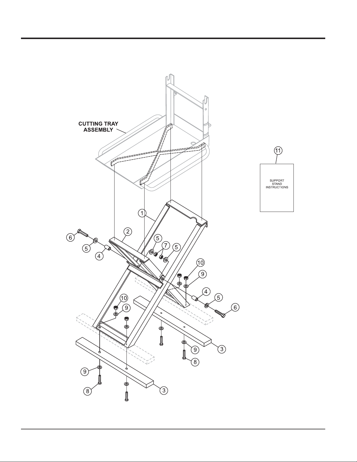
SUPPORT STAND ASSY. (Option)
SUPPORT STAND ASSY.
PAGE 56 — MP1 SERIES MASONRY SAWS — OPERATION AND PARTS MANUAL — REV. #1 (03/29/10)
Page 57

SUPPORT STAND ASSY.
SUPPORT STAND ASSY. (Option)
NO. PART NO. PART NAME QTY. REMARKS
1 23748-351 STAND ASSEMBLY OUTER 1
2 23747-351 STAND ASSEMBLY INNER 1
3 25396-001 PLATFORM STAND 2X4 TREX
WOOD POLYMER 1
4 26045-001 BUSHING 2
5 07030-006 WASHER, FLAT 3/8" 4
6 06501-010 SCREW, HHCS 3/8-16 X 1-1/4 2
7 08233-006 LOCK NUT 3/8-16" GRIPCO 2
8 06500-016 SCREW, HHCS 5/16-18 X2" 4
9 07030-005 WASHER, FLAT 5/16" 8
10 08233-005 LOCK NUT 5/16-18" GRIPCO 2
11 25949 INSTRUCTIONS, SUPPORT STAND 1
MP1 SERIES MASONRY SAWS — OPERATION AND PARTS MANUAL — REV. #1 (03/29/10) — PAGE 57
Page 58

HONDA GX160K1QXC9 — AIR CLEANER ASSY.
AIR CLEANER (CYCLONE) ASSY.
PAGE 58 — MP1 SERIES MASONRY SAWS — OPERATION AND PARTS MANUAL — REV. #1 (03/29/10)
Page 59

HONDA GX160K1QXC9 — AIR CLEANER ASSY.
AIR CLEANER (CYCLONE) ASSY.
NO. PART NO. PART NAME QTY. REMARKS
1 16271ZE1000 GASKET, ELBOW 1
2 17210ZE1505 ELEMENT, AIR CLEANER (DUAL)............ 1 ......... INCLUDES ITEMS W/
3
4# 17219733010 GASKET, AIR CLEANER COVER 1
5 17230ZE1841 COVER, AIR CLEANER (DUAL) 1
6
7# 17238ZE7010 COLLAR, AIR CLEANER 2
8# 17239733000 COLLAR B, AIR CLEANER 1
9 17410ZE1840 ELBOW, AIR CLEANER ............................ 1 ......... INCLUDES ITEMS W/#
10 17470ZE1841 CASE, PRE AIR CLEANER 1
11 17475ZE1841 CAP, PRE AIR CLEANER 1
12 17476ZE1841 GUIDE, PRE AIR CLEANER 1
13 17478ZE1841 PLATE, PRE AIR CLEANER 1
14 90300GB0900 BOLT, MUDGUARD 5
15 90325044000 WINGNUT, TOOL BOX SETTING 1
16 90325044000 WINGNUT, TOOL BOX SETTING 1
17 9405006000 NUT, FLANGE (6MM) 5
18 957010602000 BOLT, FLANGE (6X20) 1
17218ZE1505 FILTER, OUTER 1
*
17232891000 GROMMET, AIR CLEANER 1
*
*
MP1 SERIES MASONRY SAWS — OPERATION AND PARTS MANUAL — REV. #1 (03/29/10) — PAGE 59
Page 60

CAMSHAFT ASSY.
HONDA GX160K1QXC9 — CAMSHAFT ASSY.
PAGE 60 — MP1 SERIES MASONRY SAWS — OPERATION AND PARTS MANUAL — REV. #1 (03/29/10)
Page 61

HONDA GX160K1QXC9 — CAMSHAFT ASSY.
CAMSHAFT ASSY.
NO. PART NO. PART NAME QTY. REMARKS
1 14100ZE1812 CAMSHAFT ASSEMBLY ............................... 1 ....... INCLUDES ITEMS W/
2 14410ZE1010 ROD, PUSH 2
3 14431ZE1000 ARM, VALVE ROCKER 2
4 14441ZE1010 LIFTER, VALVE 2
5 14451ZE1013 PIVOT, ROCKER ARM 2
6
7 14711ZF1000 VALVE, INTAKE 1
8 14721ZF1000 VALVE, EXHAUST 1
9 14751ZF1000 SPRING, VALVE 2
10 14771ZE1000 RETAINER, INTAKE VALVE SPRING 1
11 14773ZE1000 RETAINER, EXHAUST VALVE SPRING 1
12 14781ZE1000 ROTATOR, VALVE 1
13 14791ZE1010 PLATE, PUSH ROD GUIDE 1
14 90012ZE0010 BOLT, PIVOT 8MM 2
15 90206ZE1000 NUT, PIVOT ADJ. 2
14568ZE1000 SPRING, WEIGHT RETURN 1
*
*
MP1 SERIES MASONRY SAWS — OPERATION AND PARTS MANUAL — REV. #1 (03/29/10) — PAGE 61
Page 62

CARBURETOR ASSY.
HONDA GX160K1QXC9 — CARBURETOR ASSY.
PAGE 62 — MP1 SERIES MASONRY SAWS — OPERATION AND PARTS MANUAL — REV. #1 (03/29/10)
Page 63

HONDA GX160K1QXC9 — CARBURETOR ASSY.
CARBURETOR ASSY.
NO. PART NO. PART NAME QTY. REMARKS
1
#%+ 16010ZE1812 GASKET SET 1
*
2
*
3
*
4
*
5
*
6 16024ZE1811 SCREW SET, DRAIN ............................. 1 ............. INCLUDES ITEMS W/%
7 16028ZE0005 SCREW SET B ...................................... 1 ............. INCLUDES ITEMS W/#
8
*
9 16100ZH8V21 CARBURETOR ASSEMBLY, BE65G B .. 1 ............. INCLUDES ITEMS W/
10
*
11
*
12
*
13 16211ZE1000 INSULATOR, CARBURETOR 1
14 16212ZH8800 GASKET, INSULATOR 1
15 16220ZE1020 SPACER, CARBURETOR 1
16 16221ZH8801 GASKET, INSULATOR 1
17 16610ZE1000 LEVER, CHOKE (STANDARD) .............. 1 ............. INCLUDES ITEMS W/
18
*
19
*
20
*
21 16957ZE1812 GASKET, VALVE 1
22
*
23
*
24
>
25
*
25 99101ZH70620 JET, MAIN #62 ( OPTIONAL) 1
25 99101ZH80620 JET, MAIN #62 (OPTIONAL) 1
25 99101ZH80650 JET, MAIN #65 (OPTIONAL) 1
26
*
16011ZE0005 VALVE SET, FLOAT 1
16013ZE0005 FLOAT SET 1
16015ZE0831 CHAMBER SET, FLOAT 1
16016ZH8W01 SCREW SET 1
16044ZE0005 CHOKE SET 1
16124ZE0005 SCREW, THROTTLE STOP 1
16166ZH8W00 NOZZLE, MAIN 1
16173001004 O- RING 1
>
16953ZE1812 LEVER, VALVE 1
16954ZE1812 PLATE, LEVER SETTING 1
16956ZE1811 SPRING, VALVE LEVER 1
16967ZE0811 CUP, FUEL STRAINER 1
93500030060H SCREW, PAN 3X6 2
9430520122 PIN, SPRING 2X12 1
99101ZH80680 JET, MAIN #68 1
99204ZE20400 JET SET, PILOT #40 ............................. 1 ............. INCLUDES ITEMS W/+
*
MP1 SERIES MASONRY SAWS — OPERATION AND PARTS MANUAL — REV. #1 (03/29/10) — PAGE 63
Page 64

CONTROL ASSY.
HONDA GX160K1QXC9 — CONTROL ASSY.
PAGE 64 — MP1 SERIES MASONRY SAWS — OPERATION AND PARTS MANUAL — REV. #1 (03/29/10)
Page 65

HONDA GX160K1QXC9 — CONTROL ASSY.
CONTROL ASSY.
NO. PART NO. PART NAME QTY. REMARKS
3 16500ZH8853 CONTROL ASSEMBLY, CYCLONE ............. 1 .......... INCLUDES ITEMS W/
4 16551ZE0010 ARM, GOVERNOR 1
5 16555ZE1000 ROD, GOVERNOR 1
6 16561ZE1020 SPRING, GOVERNOR 1
7 16562ZE1020 SPRING, THROTTLE RETURN 1
8
9
10
11
12
13
14
15
16
17 90013883000 BOLT, FLANGE 6X12 (CT200) 2
18 90015ZE5010 BOLT, GOVERNOR ARM 1
19
20
21
22
23
24 9405006000 NUT, FLANGE 6MM 1
16571ZH8020 LEVER, CONTROL 1
*
16574ZE1000 SPRING, LEVER 1
*
16575ZH8000 WASHER, CONTROL LEVER 1
*
16576891000 HOLDER, CABLE 1
*
16578ZE1000 SPACER, CONTROL LEVER 1
*
16580ZH8853 BASE, CONTROL (CYCLONE) 1
*
16584883300 SPRING, CONTROL ADJUSTING 1
*
16592ZE1810 SPRING, CABLE RETURN 1
*
16594883010 HOLDER, WIRE 1
*
90114SA0000 NUT, SELF- LOCK 6MM 1
*
90605230000 CIRCLIP 5MM 1
*
93500040060H SCREW, PAN 4X6 1
*
93500050250H SCREW, PAN 5X25 1
*
93500050160A SCREW, PAN 5X16 1
*
*
MP1 SERIES MASONRY SAWS — OPERATION AND PARTS MANUAL — REV. #1 (03/29/10) — PAGE 65
Page 66

HONDA GX160K1QXC9 — CRANKCASE COVER ASSY.
CRANKCASE COVER ASSY.
PAGE 66 — MP1 SERIES MASONRY SAWS — OPERATION AND PARTS MANUAL — REV. #1 (03/29/10)
Page 67

HONDA GX160K1QXC9 — CRANKCASE COVER ASSY.
CRANKCASE COVER ASSY.
NO. PART NO. PART NAME QTY. REMARKS
1 11300ZE1641 COVER ASSY., CRANKCASE U- TYPE.................... 1............. INCLUDES ITEMS W/
3 11381ZH8801 GASKET, CASE COVER (NON-ASBESTOS) 1
4 15600ZE1003 CAP ASSEMBLY, OIL FILLER ................................... 1.............INCLUDES ITEMS W/#
5 15600ZG4003 CAP ASSEMBLY, OIL FILLER ................................... 1.............INCLUDES ITEMS W/%
9# 15625ZE1003 GASKET, OIL FILLER CAP 1
10% 15625ZE1003 GASKET, OIL FILLER CAP 1
11
12 9430108140 PIN A, DOWEL 8X14 2
13 957010803200 BOLT, FLANGE 8X32 6
14
91202883005 OIL SEAL 25X41X6 1
*
961006205000 BEARING, RADIAL BALL 6205 1
*
*
MP1 SERIES MASONRY SAWS — OPERATION AND PARTS MANUAL — REV. #1 (03/29/10) — PAGE 67
Page 68

CRANKSHAFT ASSY.
HONDA GX160K1QXC9 — CRANKSHAFT ASSY.
PAGE 68 — MP1 SERIES MASONRY SAWS — OPERATION AND PARTS MANUAL — REV. #1 (03/29/10)
Page 69

HONDA GX160K1QXC9 — CRANKSHAFT ASSY.
CRANKSHAFT ASSY.
NO. PART NO. PART NAME QTY. REMARKS
3 13310ZE1601 CRANKSHAFT (Q- TYPE) 1
9 90745ZE1600 KEY 4.78X4.78X38 1
MP1 SERIES MASONRY SAWS — OPERATION AND PARTS MANUAL — REV. #1 (03/29/10) — PAGE 69
Page 70

HONDA GX160K1QXC9 — CYLINDER BARREL ASSY.
CYLINDER BARREL ASSY.
PAGE 70 — MP1 SERIES MASONRY SAWS — OPERATION AND PARTS MANUAL — REV. #1 (03/29/10)
Page 71

HONDA GX160K1QXC9 — CYLINDER BARREL ASSY.
CYLINDER BARREL ASSY.
NO. PART NO. PART NAME QTY. REMARKS
2 12000ZH8811 CYLINDER ASSEMBLY , OIL ALERT ......... 1 .......... INCLUDES ITEMS W/
3 15510ZE1033 SWITCH ASSEMBLY, OIL LEVEL 1
4 16510ZE1000 GOVERNOR ASSEMBLY ............................ 1 .......... INCLUDES ITEMS W/
5# 16511ZE1000 WEIGHT, GOVERNOR 2
6# 16512ZE1000 HOLDER, GOVERNOR WEIGHT 1
8 16531ZE1000 SLIDER, GOVERNOR 1
9 16541ZE1000 SHAFT, GOVERNOR ARM 1
10 90131ZE1000 BOLT, DRAIN PLUG 2
11 90451ZE1000 WASHER, THRUST 6MM 1
12 90601ZE1000 WASHER DRAIN PLUG 10.2MM 2
13 90602ZE1000 CLIP, GOVERNOR HOLDER 1
14
15
16 91353671003 O- RING 13.5X1.5 (ARAI) 1
17 9405010000 NUT, FLANGE 10MM 1
18 9410106800 WASHER, PLAIN 6MM 2
19 9425108000 PIN, LOCK 8MM 1
20 957010601200 BOLT, FLANGE 6X12 2
91001ZF1003 BEARING, RADIAL BALL 6205 1
*
91202883005 OIL SEAL 25X41X6 1
*
*
#
MP1 SERIES MASONRY SAWS — OPERATION AND PARTS MANUAL — REV. #1 (03/29/10) — PAGE 71
Page 72

CYLINDER HEAD ASSY.
HONDA GX160K1QXC9 — CYLINDER HEAD ASSY.
PAGE 72 — MP1 SERIES MASONRY SAWS — OPERATION AND PARTS MANUAL — REV. #1 (03/29/10)
Page 73

HONDA GX160K1QXC9 — CYLINDER HEAD ASSY.
CYLINDER HEAD ASSY.
NO. PART NO. PART NAME QTY. REMARKS
1 12210ZH8000 CYLINDER HEAD ........................................ 1 .......... INCLUDES ITEMS W/
2
3
4# 12216ZE5300 CLIP, VALVE GUIDE 1
5 12251ZF1800 GASKET, CYLINDER HEAD 1
6 12310ZE1841 COVER, HEAD 1
7 12391ZE1000 GASKET, CYLINDER HEAD COVER 1
8 15721ZE1840 TUBE, BREATHER 1
9 90013883000 BOLT, FLANGE 6X12 (CT200) 4
10 90043ZE1020 BOLT, STUD 6X10⁹ 2
11 90047ZE1000 BOLT, STUD 8X32 2
12 9430110160 PIN A, DOWEL 10X16 2
13 9500280000 CLIP, TUBE C12 2
14 957230806000 BOLT, FLANGE 8X60 4
15 9807956846 SPARK PLUG BPR6ES (NGK) 1
12204ZE1306 GUIDE, VALVE OS (OPTIONAL) 1
*
12205ZE1315 GUIDE, EXHAUST VALVE OS (OPT.) ......... 1 .......... INCLUDES ITEMS W/#
*
*
MP1 SERIES MASONRY SAWS — OPERATION AND PARTS MANUAL — REV. #1 (03/29/10) — PAGE 73
Page 74

FAN COVER ASSY.
HONDA GX160K1QXC9 — FAN COVER ASSY.
PAGE 74 — MP1 SERIES MASONRY SAWS — OPERATION AND PARTS MANUAL — REV. #1 (03/29/10)
Page 75

HONDA GX160K1QXC9 — FAN COVER ASSY.
FAN COVER ASSY.
NO. PART NO. PART NAME QTY. REMARKS
2 19610ZE1000ZA COVER, FAN *R8* BRIGHT RED 1
4 19611ZH8810 PLATE, SIDE (OIL ALERT) 1
7 90601ZH7013 CLIP, HARNESS 1
8 19630ZH8000 SHROUD 1
10 32197ZH8003 SUB- HARNESS 1
11 36100ZE1015 SWITCH ASSEMBLY, ENGINE STOP 1
11 36100ZH7003 SWITCH ASSEMBLY, ENGINE STOP 1
13 90013883000 BOLT, FLANGE 6X12 (CT200) 6
14 90022888010 BOLT, FLANGE 6X20 (CT200 1
17 34150ZH7003 ALERT UNIT, OIL 1
19 957010600800 BOLT, FLANGE 6X8 1
MP1 SERIES MASONRY SAWS — OPERATION AND PARTS MANUAL — REV. #1 (03/29/10) — PAGE 75
Page 76

FLYWHEEL ASSY.
HONDA GX160K1QXC9 — FLYWHEEL ASSY.
PAGE 76 — MP1 SERIES MASONRY SAWS — OPERATION AND PARTS MANUAL — REV. #1 (03/29/10)
Page 77

HONDA GX160K1QXC9 — FLYWHEEL ASSY.
FLYWHEEL ASSY.
NO. PART NO. PART NAME QTY. REMARKS
1 13331357000 KEY, SPECIAL WOODRUFF 25X18 1
2 19511ZE1000 FAN, COOLING 1
4 28451ZH8003 PULLEY, STARTER 1
5 31100ZE1010 FLYWHEEL 1
5 31100ZE1810 FLYWHEEL, LAMP 1
8 90201878003 NUT, SPECIAL 14MM 1
MP1 SERIES MASONRY SAWS — OPERATION AND PARTS MANUAL — REV. #1 (03/29/10) — PAGE 77
Page 78

FUEL TANK ASSY.
HONDA GX160K1QXC9 — FUEL TANK ASSY.
PAGE 78 — MP1 SERIES MASONRY SAWS — OPERATION AND PARTS MANUAL — REV. #1 (03/29/10)
Page 79

HONDA GX160K1QXC9 — FUEL TANK ASSY.
FUEL TANK ASSY.
NO. PART NO. PART NAME QTY. REMARKS
1 16854ZH8000 RUBBER, SUPPORTER 107MM 1
2 16955ZE1000 JOINT, FUEL TANK 1
3 17510ZE1020ZA TANK, FUEL *NH31* MCKINLEY WHITE 1
5 17620ZH7023 CAP, FUEL FILLER 1
6 17631ZH7003 GASKET, FUEL FILLER CAP 1
10 89218ZE1000 WRENCH, SPARK PLUG 1
11 91353671003 O-RING 13.5X1.5 (ARAI) 1
12 9405006000 NUT, FLANGE 6MM 2
13 950014500360M BULK HOSE, FUEL 4.5X3000 (4.5X140) 1
14 9500202080 CLIP, TUBE B8 2
15 957010602500 BOLT, FLANGE 6X25 1
MP1 SERIES MASONRY SAWS — OPERATION AND PARTS MANUAL — REV. #1 (03/29/10) — PAGE 79
Page 80

IGNITION COIL ASSY.
HONDA GX160K1QXC9 — IGNITION COIL ASSY.
PAGE 80 — MP1 SERIES MASONRY SAWS — OPERATION AND PARTS MANUAL — REV. #1 (03/29/10)
Page 81

HONDA GX160K1QXC9 — IGNITION COIL ASSY.
IGNITION COIL ASSY.
NO. PART NO. PART NAME QTY. REMARKS
1 30500ZE1033 COIL ASSEMBLY, IGNITION 1
2 30700ZE1013 CAP ASSEMBLY, NOISE SUPPRESSOR 1
7 36101ZE1010 WIRE, STOP SWITCH 370MM 1
11 90121952000 BOLT, FLANGE 6X25 2
MP1 SERIES MASONRY SAWS — OPERATION AND PARTS MANUAL — REV. #1 (03/29/10) — PAGE 81
Page 82

MUFFLER ASSY.
HONDA GX160K1QXC9 — MUFFLER ASSY.
PAGE 82 — MP1 SERIES MASONRY SAWS — OPERATION AND PARTS MANUAL — REV. #1 (03/29/10)
Page 83

HONDA GX160K1QXC9 — MUFFLER ASSY.
MUFFLER ASSY.
NO. PART NO. PART NAME QTY. REMARKS
1 18310ZE1821 MUFFLER, SILENT 1
2 18315ZE1000 STAY, MUFFLER 1
3 18320ZF1H51 PROTECTOR, MUFFLER 1
5 18331883810 CAP, MUFFLER 1
7 18355ZE1810 ARRESTER, SPARK (SILENT) 1
8 18381ZH8800 GASKET, MUFFLER 1
10 90016ZE1000 BOLT, FLANGE 6X13 1
11 90050ZE1000 SCREW, TAPPING 5X8 4
12 90055ZE1000 SCREW, TAPPING 4X6 3
15 94001080000S NUT, HEX. 8MM 2
16 957010601200 BOLT, FLANGE 6X12 1
MP1 SERIES MASONRY SAWS — OPERATION AND PARTS MANUAL — REV. #1 (03/29/10) — PAGE 83
Page 84

HONDA GX160K1QXC9 — PISTON AND RINGS ASSY.
PISTON AND RINGS ASSY.
PAGE 84 — MP1 SERIES MASONRY SAWS — OPERATION AND PARTS MANUAL — REV. #1 (03/29/10)
Page 85

HONDA GX160K1QXC9 — PISTON AND RINGS ASSY.
PISTON AND RINGS ASSY.
NO. PART NO. PART NAME QTY. REMARKS
1 13010ZF1023 RING SET, PISTON (STANDARD) 1
1 13010ZH8941 RING SET, PISTON (STANDARD 1
1 13011ZF1023 RING SET, PISTON (OS 0.25) (OPTIONAL) 1
1 13011ZH8941 RING SET, PISTON (OS 0.25) (OPTIONAL) 1
1 13012ZF1023 RING SET, PISTON (OS 0.50) (OPTIONAL) 1
1 13012ZH8941 RING SET, PISTON (OS 0.50) (OPTIONAL) 1
1 13013ZF1023 RING SET, PISTON (0.75) (OPTIONAL) 1
1 13013ZH8941 RING SET, PISTON (0.75 (OPTIONAL) 1
2 13101ZH8000 PISTON, STANDARD 1
2 13102ZH8000 PISTON , OS 0.25 (OPTIONAL) 1
2 13103ZH8000 PISTON, OS 0.50 (OPTIONAL) 1
2 13104ZH8000 PISTON, 0.75 (OPTIONAL) 1
3 13111ZE1000 PIN, PISTON 1
4 13200ZE1010 ROD ASSEMBLY, CONNECTING ....................... 1 ......... INCLUDES ITEMS W/
5
6 90551ZE1000 CLIP, PISTON PIN 18MM 2
90001ZE1000 BOLT, CONNECTING ROD 2
*
*
MP1 SERIES MASONRY SAWS — OPERATION AND PARTS MANUAL — REV. #1 (03/29/10) — PAGE 85
Page 86

HONDA GX160K1QXC9 — RECOIL STARTER ASSY.
RECOIL STARTER ASSY.
PAGE 86 — MP1 SERIES MASONRY SAWS — OPERATION AND PARTS MANUAL — REV. #1 (03/29/10)
Page 87

HONDA GX160K1QXC9 — RECOIL STARTER ASSY.
RECOIL STARTER ASSY.
NO. PART NO. PART NAME QTY. REMARKS
1 28400ZH8013ZA STARTER ASSY., RECOIL *R8*BRIGHT RED ............. 1 ........ INCLUDES ITEMS W/
2
3
4
5
6
7
8
9
10
11
12 90008ZE2003 BOLT, FLANGE 6X10 3
28410ZH8003ZA CASE, RECOIL STARTER *R8* BRIGHT RED 1
*
28420ZH8013 REEL, RECOIL STARTER 1
*
28422ZH8013 RATCHET, STARTER 2
*
28433ZH8003 GUIDE, RATCHET 1
*
28441ZH8003 SPRING, FRICTION 1
*
28442ZH8003 SPRING, RECOIL STARTER 1
*
28443ZH8003 SPRING, RETURN 2
*
28461ZH8003 KNOB, RECOIL STARTER 1
*
28462ZH8003 ROPE, RECOIL STARTER 1
*
90003ZH8003 SCREW, SETTING 1
*
*
MP1 SERIES MASONRY SAWS — OPERATION AND PARTS MANUAL — REV. #1 (03/29/10) — PAGE 87
Page 88

GASKET KIT ASSY.
HONDA GX160K1QXC9 — GASKET KIT ASSY.
NO ART WORK
PAGE 88 — MP1 SERIES MASONRY SAWS — OPERATION AND PARTS MANUAL — REV. #1 (03/29/10)
Page 89

HONDA GX160K1QXC9 — GASKET KIT ASSY.
GASKET KIT ASSY.
NO. PART NO. PART NAME QTY. REMARKS
1
2
3
4
5
6
7 06111ZH8405 GASKET KIT .......................................................... 1 .......... INCLUDES ITEMS W/
11381ZH8801 GASKET, CASE COVER (NON- ASBESTOS 1
*
12251ZF1800 GASKET, CYLINDER HEAD 1
*
12391ZE1000 GASKET, CYLINDER HEAD COVER 1
*
16212ZH8800 GASKET, INSULATOR 1
*
16221ZH8801 GASKET, CARBURETOR 1
*
18381ZH8800 GASKET, MUFFLER 1
*
*
MP1 SERIES MASONRY SAWS — OPERATION AND PARTS MANUAL — REV. #1 (03/29/10) — PAGE 89
Page 90

LABELS ASSY.
HONDA GX160K1QXC9 — LABELS ASSY.
PAGE 90 — MP1 SERIES MASONRY SAWS — OPERATION AND PARTS MANUAL — REV. #1 (03/29/10)
Page 91

HONDA GX160K1QXC9 — LABELS ASSY.
LABELS ASSY.
NO. PART NO. PART NAME QTY. REMARKS
1 87521ZH8020 EMBLEM, 5.5 1
3 87522ZH9000 LABEL, CAUTION 1
6 87528ZE1810 MARK, CHOKE 1
8 87532ZH8810 MARK, OIL ALERT (E) 1
10 87534ZE1841 LABEL, AIR CLEANER CAUTION 1
11 87535ZE1840 MARK, AIR CLEANER SALES POINT 1
MP1 SERIES MASONRY SAWS — OPERATION AND PARTS MANUAL — REV. #1 (03/29/10) — PAGE 91
Page 92

TERMS AND CONDITIONS OF SALE — PARTS
PAYMENT TERMS
Terms of payment for parts are net 30 days.
FREIGHT POLICY
All parts orders will be shipped collect or
prepaid with the charges added to the invoice.
All shipments are F.O.B. point of origin.
Multiquip’s responsibility ceases when a
signed manifest has been obtained from the
carrier, and any claim for shortage or damage
must be settled between the consignee and
the carrier.
MINIMUM ORDER
The minimum charge for orders from Multiquip
is $15.00 net. Customers will be asked for
instructions regarding handling of orders not
meeting this requirement.
RETURNED GOODS POLICY
Return shipments will be accepted and
credit will be allowed, subject to the following
provisions:
A Returned Material Authorization 1.
must be approved by Multiquip prior to
shipment.
To obtain a Return Material Authorization, 2.
a list must be provided to Multiquip
Parts Sales that defines item numbers,
quantities, and descriptions of the items
to be returned.
The parts numbers and descriptions a.
must match the current parts price
list.
The list must be typed or computer b.
generated.
The list must state the reason(s) c.
for the return.
The list must reference the sales d.
order(s) or invoice(s) under
which the items were originally
purchased.
The list must include the name e.
and phone number of the person
requesting the RMA.
A copy of the Return Material Authorization 3.
must accompany the return shipment.
Freight is at the sender’s expense. All 4.
parts must be returned freight prepaid to
Multiquip’s designated receiving point.
Parts must be in new and resalable 5.
condition, in the original Multiquip
package (if any), and with Multiquip part
numbers clearly marked.
The following items are not returnable:6.
Obsolete parts. (If an item is in the a.
price book and shows as being
replaced by another item, it is
obsolete.)
Any parts with a limited shelf life b.
(such as gaskets, seals, “O” rings,
and other rubber parts) that were
purchased more than six months
prior to the return date.
Any line item with an extended c.
dealer net price of less than
$5.00.
Special order items.d.
Electrical components.e.
Paint, chemicals, and lubricants.f.
Decals and paper products.g.
Items purchased in kits.h.
The sender will be notified of any material 7.
received that is not acceptable.
Such material will be held for five 8.
working days from notification, pending
instructions. If a reply is not received
within five days, the material will be
returned to the sender at his expense.
Credit on returned parts will be issued 9.
at dealer net price at time of the original
purchase, less a 15% restocking
charge.
In cases where an item is accepted, for 10.
which the original purchase document
can not be determined, the price will be
based on the list price that was effective
twelve months prior to the RMA date.
Credit issued will be applied to future 11.
purchases only.
PRICING AND REBATES
Prices are subject to change without prior
notice. Price changes are effective on a
specific date and all orders received on or
after that date will be billed at the revised price.
Rebates for price declines and added charges
for price increases will not be made for stock
on hand at the time of any price change.
Multiquip reserves the right to quote and
sell direct to Government agencies, and to
Original Equipment Manufacturer accounts
who use our products as integral parts of their
own products.
SPECIAL EXPEDITING SERVICE
A $35.00 surcharge will be added to the
invoice for special handling including bus
shipments, insured parcel post or in cases
where Multiquip must personally deliver the
parts to the carrier.
LIMITATIONS OF SELLER’S LIABILITY
Multiquip shall not be liable hereunder for
damages in excess of the purchase price of
the item with respect to which damages are
claimed, and in no event shall Multiquip be
liable for loss of profit or good will or for any
other special, consequential or incidental
damages.
LIMITATION OF WARRANTIES
No warranties, express or implied, are
made in connection with the sale of parts or
trade accessories nor as to any engine not
manufactured by Multiquip. Such warranties
made in connection with the sale of new,
complete units are made exclusively by a
statement of warranty packaged with such
units, and Multiquip neither assumes nor
authorizes any person to assume for it
any other obligation or liability whatever in
connection with the sale of its products. Apart
from such written statement of warranty,
there are no warranties, express, implied or
statutory, which extend beyond the description
of the products on the face hereof.
Effective: February 22, 2006
PAGE 92 — MP1 SERIES MASONRY SAWS — OPERATION AND PARTS MANUAL — REV. #1 (03/29/10)
Page 93

NOTES
MP1 SERIES MASONRY SAWS — OPERATION AND PARTS MANUAL — REV. #1 (03/29/10) — PAGE 93
Page 94

OPERATION AND PARTS MANUAL
©
HERE’S HOW TO GET HELP
PLEASE HAVE THE MODEL AND SERIAL
NUMBER ON-HAND WHEN CALLING
UNITED STATES
Multiquip Corporate Office MQ Parts Department
18910 Wilmington Ave.
Carson, CA 90746
Contact: mq@multiquip.com
Mayco Parts Warranty Department
Tel. (800) 421-1244
Fax (800) 537-3927
800-427-1244
310-537-3700
Fax: 800-672-7877
Fax: 310-637-3284
800-306-2926
310-537-3700
Service Department Technical Assistance
800-421-1244
310-537-3700
Fax: 800-672-7877
Fax: 310-637-3284
Fax: 310-537-4259 800-478-1244 Fax: 310-631-5032
800-421-1244, Ext. 279
310-537-3700, Ext. 279
Fax: 310-537-1173
MEXICO UNITED KINGDOM
MQ Cipsa Multiquip (UK) Limited Head Office
Carr. Fed. Mexico-Puebla KM 126.5
Momoxpan, Cholula, Puebla 72760 Mexico
Contact: pmastretta@cipsa.com.mx
Tel: (52) 222-225-9900
Fax: (52) 222-285-0420
Unit 2, Northpoint Industrial Estate,
Global Lane,
Dukinfield, Cheshire SK16 4UJ
Contact: sales@multiquip.co.uk
Tel: 0161 339 2223
Fax: 0161 339 3226
CANADA
Multiquip
4110 Industriel Boul.
Laval, Quebec, Canada H7L 6V3
Contact: jmartin@multiquip.com
COPYRIGHT 2010, MULTIQUIP INC.
Multiquip Inc and the MQ logo are registered trademarks of Multiquip Inc. and may not be used, reproduced, or altered without written permission. All other trademarks are the property
of their respective owners and used with permission.
This manual
The information and specifications included in this publication were in effect at the time of approval for printing. Illustrations, descriptions, references and technical data contained in
this manual are for guidance only and may not be considered as binding. Multiquip Inc. reserves the right to discontinue or change specifications, design or the information published
in this publication at any time without notice and without incurring any obligations.
MUST accompany the equipment at all times. This manual is considered a permanent part of the equipment and should remain with the unit if resold.
Tel: (450) 625-2244
Tel: (877) 963-4411
Fax: (450) 625-8664
Your Local Dealer is:
 Loading...