

Page 1

OPERATION AND PARTS MANUAL
SERIES
MODEL MG30T2D
MODEL MG30M2D
PLASTER MORTAR PUMPS
MODEL MG30T3D
MODEL MG30M3D
FIREPROOFING PUMPS
Revision #3 (09/15/11)
To find the latest revision of this
publication, visit our website at:
www.multiquip.com
THIS MANUAL MUST ACCOMPANY THE EQUIPMENT AT ALL TIMES.
Page 2
Diesel engine exhaust and some of
PAGE 2 — MAYCO MG-30 PUMP — OPERATION AND PARTS MANUAL — REV. #3 (09/15/11)
Page 3

MAYCO MG-30 PUMP — OPERATION AND PARTS MANUAL — REV. #3 (09/15/11) — PAGE 3
Page 4

TABLE OF CONTENTS
Table of Contents .................................................... 4
Parts Ordering Procedures ..................................... 5
Safety Message Slert Dymbols ............................... 6
Rules for Safe Operation .................................... 8-10
Operation and Safety Decals ........................... 12-13
Specifications ........................................................ 14
Dimensions (MG30-M2D Mobile unit) .................. 16
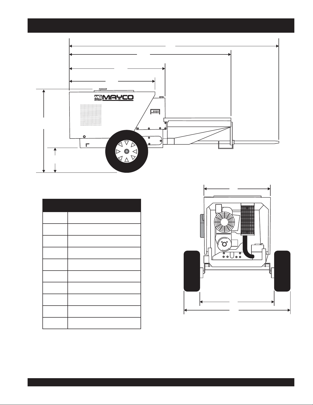
Dimensions (MG30-T2D Tag unit) ....................... 17
General Information ......................................... 18-22
MQ MAYCO MG-30 Mobile/Tag Units
Plaster/Fireproofing Pump
Application........................................................ 23-26
Mixer Major Components ................................. 26-27
MG30 M2D Major Components ....................... 28-29
Hatz 8.5 HP Engine Components .................... 30-31
Pre-Inspection (Mixer) ...................................... 32-34
Initial Start-Up (Mixer Mobile only) ........................ 35
Pre-Inspection (Pump) ..................................... 36-39
Initial Start-Up (Pump) .......................................... 40
Initial Start-Up/Operation ...................................... 41
Remote Operation ................................................. 42
Towing Guidelines ............................................ 43-45
Trailer Safety Guidelines................................... 46-47
Maintenance (Mixer) ........................................ 48-49
Maintenance (Pump) ........................................ 50-53
Troubleshooting (Engine) ...................................... 54
Troubleshooting (Engine/Mixer) ............................ 55
Troubleshooting (Pump) ........................................ 56
Wiring Diagram ................................................ 57-58
Power Module Layout ............................................ 59
PARTS ILLUSTRATIONS
Explanation of Code in Remarks Column ............. 60
Suggested Spare Parts ......................................... 61
Decal Placement .............................................. 62-63
Frame Assembly .............................................. 64-65
Hood Assembly ................................................ 66-67
Hopper Assembly ............................................. 68-69
Chassis Assembly ............................................ 70-71
Compressor Assembly ..................................... 72-43
Fuel Tank Assembly ......................................... 74-75
Piston Oiler Tank Assembly .............................. 76-77
Rocker Arm Assembly ...................................... 78-79
Push Rod (3.5-Inch) Assembly ........................ 80-81
Push Rod (3.75-Inch) Assembly ...................... 82-83
Crankshaft and Gear Box Assembly ................ 84-85
Battery Assembly ............................................. 86-87
Tag Unit Axle Assembly .................................... 88-89
Mobile Unit Axle Assembly ............................... 90-91
Control Box Assembly ...................................... 92-93
Manifold (2-inch Outlet) Assembly ................... 94-95
Pressure Relief Valve (2-Inch Outlet) Assembly .. 96-97
Manifold (3-Inch Outlet) Assembly ................... 98-99
Pressure Relief Valve (3-inch Outlet) Assembly ..... 100-101
Lubrication Panel Assembly ........................ 102-103
Remote Control Cable Assembly .................104-105
Tag Unit Trailer Assembly ............................. 106-107
Hatz 2M41LZ Engine Assembly ................... 108-109
Hatz 1B30 Engine (Clutch) Assembly .......... 110-111
Mixing Drum Assembly................................. 112-113
Paddle Shaft Assembly................................ 114-115
Frame Assembly .......................................... 116-117
Cab Assembly .............................................. 118-119
Transmission Assembly ................................ 120-121
HATZ 1B30 DIESEL ENGINE
Spare Parts Kit Assembly ............................. 122-123
Accessories Assembly.................................. 124-125
Crankcase and Engine Mount Assembly ..... 126-127
Crankshaft Assembly ................................... 128-129
Camshaft Assembly ..................................... 130-131
Piston Assembly ........................................... 132-133
Cylinder Head Assembly ..............................134-135
Oil Pump/Governor Assembly ...................... 136-139
Timing Cover Assembly ............................... 140-141
Flywheel Assembly ....................................... 142-143
Fuel Injection Assembly ............................... 144-147
Recoil Starter Assembly ............................... 148-149
Air Duct Assembly ........................................ 150-153
Crankcase Breather Assembly..................... 154-155
Fuel Tank Assembly ..................................... 156-157
Air Filter Assembly ....................................... 158-159
Muffler Assembly .......................................... 160-161
Starter/Alternator Assembly ......................... 162-163
Electronic Components Assembly................ 164-165
Speed Control Assembly .............................. 166-167
Terms and Conditions of Sale— Parts ................ 168
NOTE
Specification and part number are
subject to change without notice.
PAGE 4 — MAYCO MG-30 PUMP — OPERATION AND PARTS MANUAL — REV. #3 (09/15/11)
Page 5
r
PARTS ORDERING PROCEDURES
Ordering parts has never been easier!
Choose from three easy options:
January 1
Effective:
st
, 2006
Best Deal!
Order via Internet (Dealers Only):
Order parts on-line using Multiquip’s SmartEquip website!
■ View Parts Diagrams
■ Order Parts
■ Print Specification Information
Goto www.multiquip.com and click on
Order Parts
Order via Fax (Dealers Only):
All customers are welcome to order parts via Fax.
Domestic (US) Customers dial:
1-800-6-PARTS-7 (800-672-7877)
Non-Dealer Customers:
Contact your local Multiquip Dealer for
parts or call 800-427-1244 for help in
locating a dealer near you.
to log in and save!
Order via Phone:
If you have an MQ Account, to obtain a Username
and Password, E-mail us at: parts@multiquip.
com.
To obtain an MQ Account, contact you
District Sales Manager for more information.
Use the internet and qualify for a 5% Discount
on Standard orders for all orders which include
complete part numbers.*
Fax your order in and qualify for a 2% Discount
on Standard orders for all orders which include
complete part numbers.*
Domestic (US) Dealers Call:
1-800-427-1244
International Customers should contact
their local Multiquip Representatives for
Parts Ordering information.
Note: Discounts Are Subject To Change
Note: Discounts Are Subject To Change
When ordering parts, please supply:
❒ Dealer Account Number
❒ Dealer Name and Address
❒ Shipping Address (if different than billing address)
❒ Return Fax Number
❒ Applicable Model Number
❒ Quantity, Part Number and Description of Each Part
NOTICE
All orders are treated as Standard Orders and will
ship the same day if received prior to 3PM PST.
❒ Specify Preferred Method of Shipment:
✓ UPS/Fed Ex ✓ DHL
■ Priority One ✓ Tr uck
■ Ground
■ Next Day
■ Second/Third Day
www.multiquip.com
WE ACCEPT ALL MAJOR CREDIT CARDS!
MAYCO MG-30 PUMP — OPERATION AND PARTS MANUAL — REV. #3 (09/15/11) — PAGE 5
Page 6
MG-30 PUMP — SAFETY MESSAGE ALERT SYMBOLS
FOR YOUR SAFETY AND THE SAFETY OF OTHERS!
Safety precautions should be followed at all times when operating
this equipment. Failure to read and understand the Safety
Messages and Operating Instructions could result in injury to
yourself and others.
This Owner's Manual has been
developed to provide complete
NOTE
Before using this pump, ensure that the operating
individual has read and understands all instructions in this
manual.
instructions for the safe and efficient
operation of the Multiquip MAYCO
MG30-M (Mobile Unit) and
MG30-T (Tag Unit) plaster
fireproofing
engine manufacturers instructions for
data relative to its safe operation.
pump. Refer to the
and
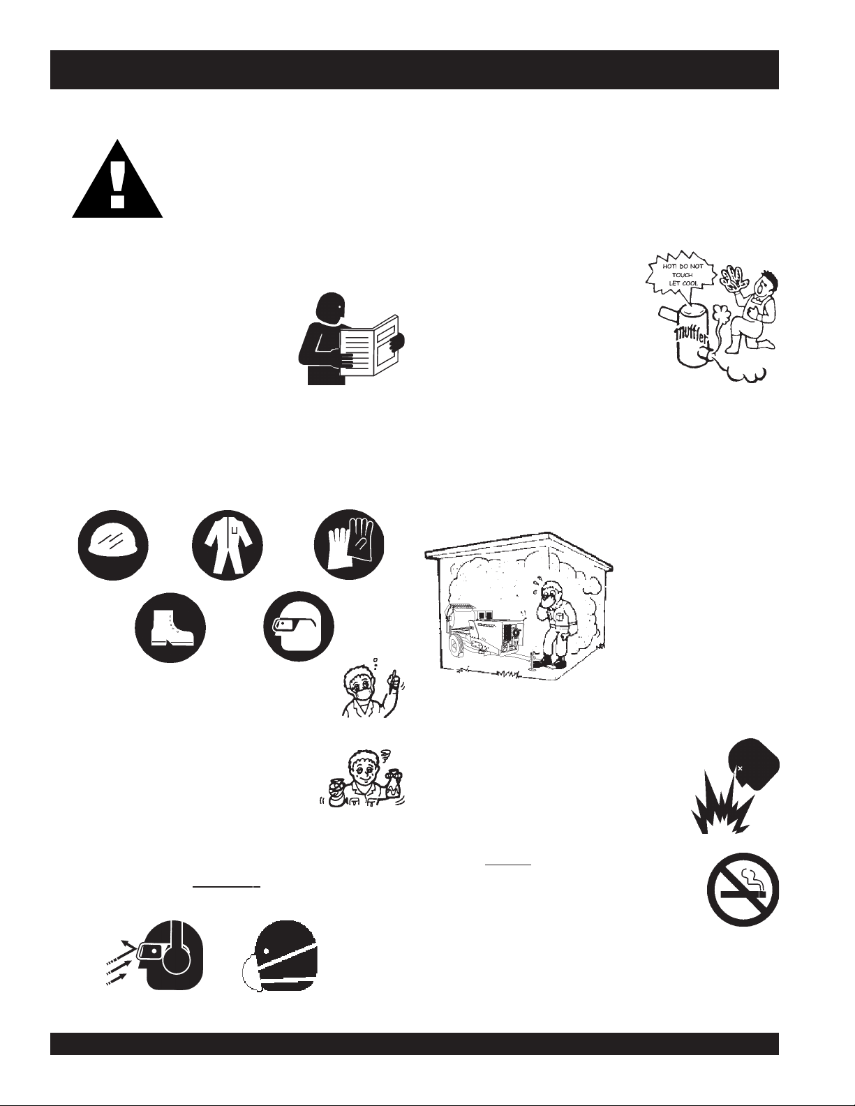
HAZARD SYMBOLS
SAFETY MESSAGE ALERT SYMBOLS
The three (3) Safety Messages shown below will inform you
about potential hazards that could injure you or others. The
Safety Messages specifically address the level of exposure to
the operator, and are preceded by one of three words: DANGER,
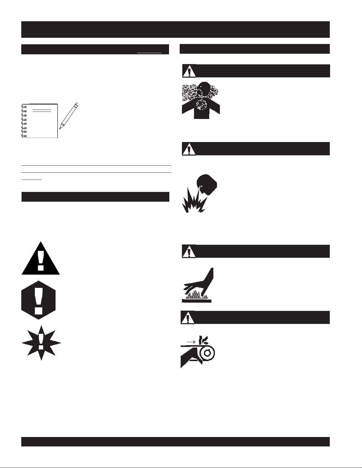
Lethal Exhaust Gases
Diesel engine exhaust gases contain poisonous
carbon monoxide. This gas is colorless and
odorless, and can cause death if inhaled.
NEVER operate this equipment in a confined
area or enclosed structure that does not
provide ample free flow air.
Explosive Fuel
Diesel fuel
vapors can cause an explosion if ignited. DO
NOT start the engine near spilled fuel or
combustible fluids. DO NOT fill the fuel tank
while the engine is running or hot. DO NOT
overfill tank, since spilled fuel could ignite if it
comes into contact with hot engine parts or
sparks from the ignition system. Store fuel in
approved containers, in well-ventilated areas
and away from sparks and flames. NEVER
use fuel as a cleaning agent.
is extremely flammable, and its
DANGER: You WILL be KILLED or
SERIOUSLY injured if you do not follow
directions.
WARNING: You CAN be KILLED or
SERIOUSLY injured if you do not follow
directions.
CAUTION: You CAN be injured if you
do not follow directions.
Potential hazards associated with operation of the pump will be
referenced with Hazard Symbols which appear throughout this
manual, and will be referenced in conjunction with Safety
Message Alert Symbols.
Burn Hazards
Engine components can generate extreme heat.
To prevent burns, DO NOT touch these areas
while the engine is running or immediately after
operations. NEVER operate the engine with
heat shields or heat guards removed.
Rotating Parts
NEVER operate equipment with covers, or
guards removed. Keep
and clothing away from all moving parts to
prevent injury.
fingers, hands, hair
PAGE 6 — MAYCO MG-30 PUMP — OPERATION AND PARTS MANUAL — REV. #3 (09/15/11)
Page 7
MG-30 PUMP — SAFETY MESSAGE ALERT SYMBOLS
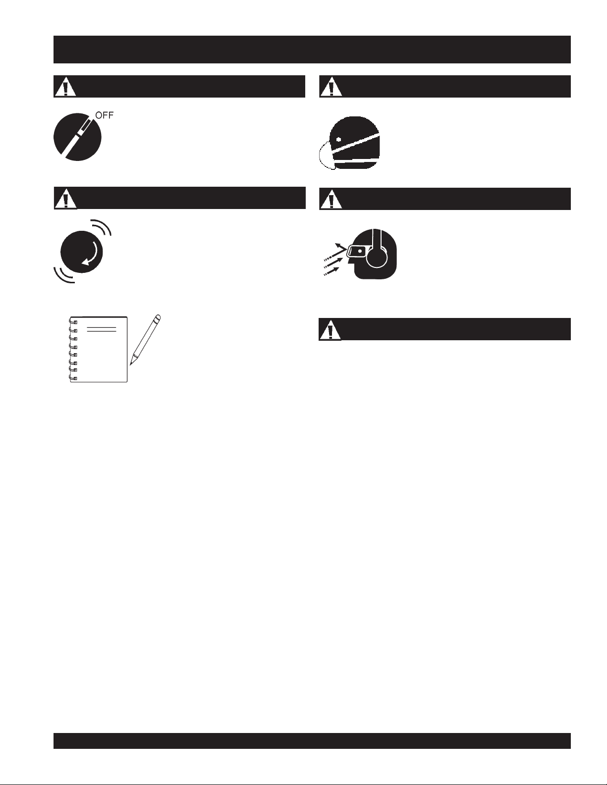
Accidental Starting
ALWAYS place the ON/OFF switch in the OFF
position. NEVER perform maintenance on the
unit with the ignition key in the ON position.
Over Speed Conditions
NEVER tamper with the factory settings of the
engine governor or settings. Personal injury
and damage to the engine or equipment can
result if operating in speed ranges above
maximum allowable.
This
pump
surrounding environment could
NOTE
be damaged if you do not follow
instructions.
, other property, or the
Respiratory Hazard
ALWAYS wear approved
protection.
respiratory
Sight and Hearing hazard
ALWAYS wear approved
protection.
eye
and
hearing
Equipment Damage Messages
Other important messages are provided throughout this manual
to help prevent damage to your plaster and fireproofing pump,
other property, or the surrounding environment.
MAYCO MG-30 PUMP — OPERATION AND PARTS MANUAL — REV. #3 (09/15/11) — PAGE 7
Page 8
MG-30 PUMP — RULES FOR SAFE OPERATION
■
CAUTION:
Failure to follow instructions in this manual
may lead to serious injury or even
This equipment is to be operated by
trained and qualified personnel only! This
equipment is for industrial use only.
The following safety guidelines should always be used when
operating the MG30-M2D (Mobile Unit) and MG30-T2D (Tag
Unit) plaster and fireproofing pump:
GENERAL SAFETY
■
DO NOT operate or service this equipment
before reading this entire manual.
■
This equipment should not be operated by persons under 18
years of age.
■
NEVER operate this equipment without proper protective
clothing, shatterproof glasses, steel-toed boots and other
protective devices required by the job.
■
NEVER operate this equipment when not feeling
well due to fatigue, illness or taking medicine.
■
NEVER operate this equipment under the
influence or drugs or alcohol.
■
ALWAYS check the machine for loosened threads or bolts
before starting.
■
ALWAYS wear proper respiratory (mask),
protection equipment when operating the pump .
hearing
death!
and
eye
Whenever necessary, replace nameplate, operation and
safety decals when they become difficult read.
■
Manufacture does not assume responsibility for any accident
due to equipment modifications.
■
NEVER use accessories or attachments, which are not
recommended by Multiquip for this equipment. Damage to
the equipment and/or injury to user may result.
■
NEVER touch the hot exhaust manifold,
muffler or cylinder. Allow these parts to
cool before servicing engine or pump .
■
High Temperatures – Allow the engine to cool before adding
fuel or performing service and maintenance functions. Contact
with
■
The engine section of this pump requires an adequate free
flow of cooling air.
■
ALWAYS refuel in a well-ventilated area, away from sparks
and open flames.
■
ALWAYS use extreme caution when
working with flammable liquids. When
refueling, stop the engine and allow it to
cool.
■
NEVER
Fire or explosion could result from
vapors
hot!
components can cause serious burns.
smoke
NEVER
around or near the machine.
operate the pump in any enclosed
or narrow area where free
flow of the air is restricted. If
the air flow is restricted it
will cause serious damage
to the pump or engine and
may cause injury to
people. Remember the
pump's engine gives off
DEADLY
gas.
carbon monoxide
fuel
, or if fuel is spilled on a
hot!
engine.
■
NEVER operate the pump in an explosive
atmosphere or near combustible materials. An explosion or
fire could result causing severe
■
Topping-off to filler port is dangerous, as it tends to spill fuel.
PAGE 8 — MAYCO MG-30 PUMP — OPERATION AND PARTS MANUAL — REV. #3 (09/15/11)
bodily harm or even death.
Page 9

MG-30 PUMP — RULES FOR SAFE OPERATION
■
ALWAYS remove the
unattended.
■
ALWAYS block the
ignition key
wheels
on the unit when using on a
when leaving the pump
Transporting
■
■
slope.
■
ALWAYS maintain this equipment in a safe operating
■
condition at all times.
■
ALWAYS stop the engine before servicing, adding fuel or oil.
■
NEVER run engine without air filter. Severe engine damage
may occur.
■
ALWAYS be sure the operator is familiar with proper safety
precautions and operation techniques before using pump.
■
ALWAYS store equipment properly when it is not being used.
Equipment should be stored in a clean, dry location out of
the reach of children.
■
DO NOT operate this equipment unless all guards and safety
Towing
■
■
■
■
devices are attached and in place.
■
CAUTION must be exercised while servicing this equipment.
■
Rotating and moving parts can cause injury if contacted.
■
Keep all
from the equipment at all times.
■
Before start-up, check the hopper and remove all foreign
matter and debris.
inexperienced
and
unauthorized
people away
■
■
■
ALWAYS shutdown engine before transporting the pump.
Tighten fuel tank cap securely and close fuel valve to prevent
fuel from spilling.
Drain fuel when transporting pump over long distances or
bad roads.
Before towing, check the hitch and secure the safety chain to
the towing vehicle.
When towing, an adequate safety chain must be fastened to
the frame, refer to pages 44 and 45.
Tow only with a vehicle and hitch rated to pull a 5,000 lbs.
load.
If unit is equipped with ball hitch coupler, use only 2" all steel
ball rated for minimum of 5,000 lbs. Use 1" hardened steel
pull pin, if not equipped with ball hitch.
This equipment shall not be towed or operated by individuals
who cannot read understand the signs, decals or operating
instructions.
When towing at night,
always
have rear tail lights ON.
DO NOT tow unit with hopper full of material.
DO NOT tow unit with hoses attached.
■
DO NOT use worn or damaged hose couplings, inspect all
■
hoses and couplings for wear. Replace any worn or defective
hose or couplings immediately.
■
Keep hands out of the hopper when the engine is running.
■
DO NOT operate unit with the
■
DO NOT disconnect hose couplings or nozzle while under
hood open
.
Maintenance Safety
■
■
pressure. Relieve pressure by manually activating pressure
relief valve at manifold.
■
Unauthorized equipment modifications will void all
■
■
warranties.
■
Check all fasteners periodically for tightness. Also check
■
towing tongue bolt, lock nut and wheel lug nuts for wear.
■
Test the
pump's ON/OFF
switch. The purpose of this test is
■
to shut down the engine.
■
Refer to the
questions or information
Engine Owner's Manual
for engine technical
recommended by Multiquip for this
equipment. Damage to the equipment and or injury to user
may result.
DO NOT tow unit in excess of 45 MPH on highways..
NEVER lubricate components or attempt service on a running
pump .
ALWAYS allow the pump a proper amount of time to cool
before servicing.
Keep the pump in proper running condition.
Fix damage to the pump immediately and always replace
broken parts.
Dispose of hazardous waste properly. Examples of potentially
hazardous waste are used motor oil, fuel and fuel filters.
DO NOT use plastic containers to dispose of hazardous
waste.
MAYCO MG-30 PUMP — OPERATION AND PARTS MANUAL — REV. #3 (09/15/11) — PAGE 9
Page 10
MG-30 PUMP — RULES FOR SAFE OPERATION
Emergencies
■
ALWAYS know the location of the nearest
■
ALWAYS know the location of the nearest and
fire extinguisher
first aid kit
.
.
■
In emergencies
nearest phone or
Also know the phone numbers of the nearest
ambulance, doctor
information will be invaluable in the case of an
emergency.
always
know the location of the
keep a phone on the job site
and
fire department
.
. This
PAGE 10 — MAYCO MG-30 PUMP — OPERATION AND PARTS MANUAL — REV. #3 (09/15/11)
Page 11

NOTE PAGE
MAYCO MG-30 PUMP — OPERATION AND PARTS MANUAL — REV. #3 (09/15/11) — PAGE 11
Page 12
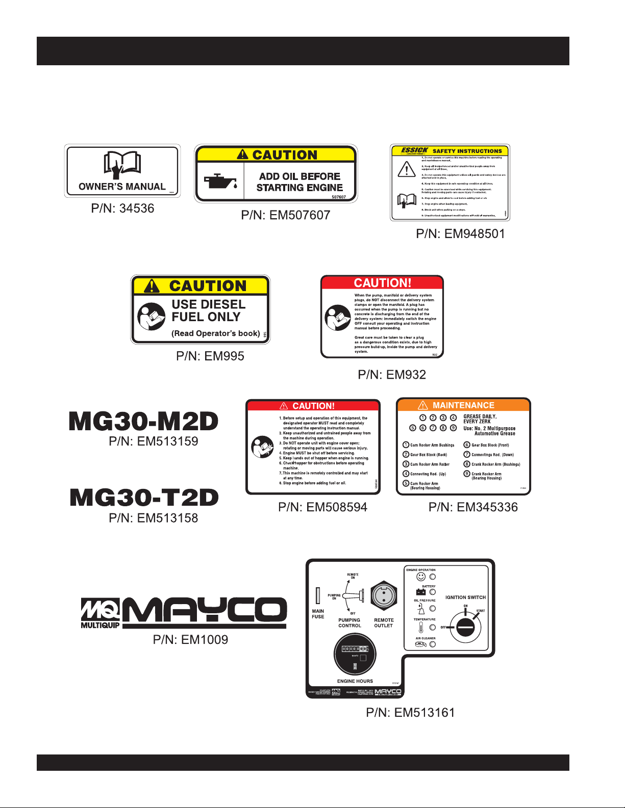
MG-30 PUMP — OPERATION AND SAFETY DECALS
Machine Safety Decals
The MG-30 mortar and plaster pump is equipped with a number of safety decals. These decals are provided for operator safety and
maintenance information. Figure 1 below illustrates these decals as they appear on the machine. Should any of these decals
become unreadable, replacements can be obtained from your dealer.
Figure 1. MG-30 Operation and Safety Decals (Pump Only)
PAGE 12 — MAYCO MG-30 PUMP — OPERATION AND PARTS MANUAL — REV. #3 (09/15/11)
Page 13
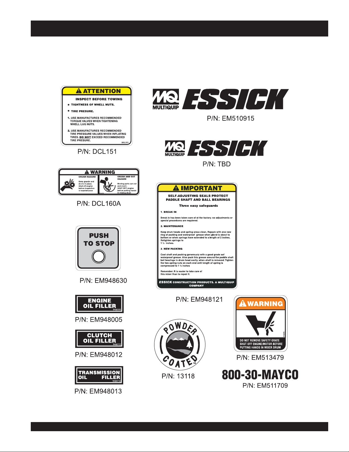
MG-30 PUMP — OPERATION AND SAFETY DECALS
Machine Safety Decals
The Essick EM 120SM mortar and plaster mixer is equipped with a number of safety decals. These decals are provided for operator
safety and maintenance information. Figure 2 below illustrates these decals as they appear on the mixer. Should any of these decals
become unreadable, replacements can be obtained from your dealer.
Figure 2. MG-30 Operation and Safety Decals (Mixer Only)
MAYCO MG-30 PUMP — OPERATION AND PARTS MANUAL — REV. #3 (09/15/11) — PAGE 13
Page 14
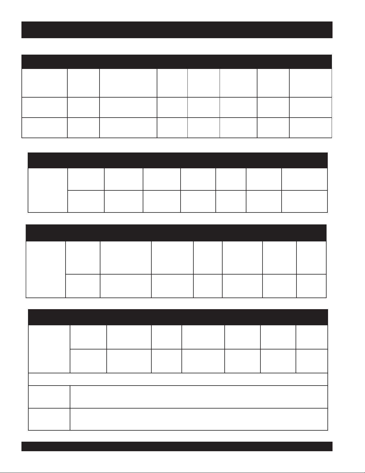
MG-30 PUMP — SPECIFICATIONS
)pmuP(snoitacificepS.1elbaT
03-GM-ledoMgnipmuP
retsalP.uc5.6
gnifoorperiF.uc9
S021ME
)kcissE(
etaR
.sdy.rh/
.rh/.sdy
gaB
yticapaC
0.4-5.3.tf.uc
lairetaM
rednilyC
)ekortSxretemaiD(
.ni6x05.3
).mc42.51x98.8(
.ni8x57.3
(
).mc23.02x25.9
pmuP
erusserP
ISP0001.ni2
ISP0001.ni3
dlofinaM
.aiDteltuO
.mc80.5(
)
).mc26.7(
rosserpmoC
rednilyC-2
notsiP
@MFC01
ISP001
@MFC01
ISP001
reppoH
yticapaC
.tf.uc9
)sretil(552
.tf.uc9
)sretil(552
leuF
yticapaC
)leseiD2.oN(
.lag3.5
)sretil02(
.lag3.5
)sretil02(
)rexiM(snoitacificepS.2elbaT
murD
yticapaC
21
)sretil043(
enignEevirDpmuD
leseiDztaH
lacinahceMlaunaM.ni57
03B1ledoM
egrahcsiD
noitcA
thgieH
thgieW
)sleehwssel(
.sbl090,1
).mc191(
).gk494(
)enignEZL14M2ZTAH(snoitacificepS.3elbaT
.oN
leseiDZTAH
srednilyC
ledoM
ekortSxeroBtnemecalpsiDeldI
liOebuL
deepS
yticapaC
yrettaB
W
thgie
epyT
niM/xaM
ZL14M2
2.ni31.4x20.4
).mm501x201(
.ni.uc7.401
)sretil617.1(
008
s'MPR
.stq2.3/8.5
)sretil0.3/5.5(
V21
hA341/88
.sbl294
).gk322(
)enignE03B1ZTAH(snoitacificepS.4elbaT
leseiDZTAH
03B1ledoM
delooC-riA
liOenignE
epyT
leuFepyT
.oN
srednilyC
1.mc.uc743
tnemecalpsiDeldI
)sretil743.(
liOebuL
deepS
008
s'MPR
yticapaC
.stq50.1
)sretil1(
riAepyT
renaelC
yrD
tnemelE
gnitratS
thgieW
dohteM
lioceR
tratS
.sbl77.38
).gk83(
-DC-IPAro@DP-5D-4D-CMCC
DPHSroGC-FC-EC
-2A/1A9682SB10615NID-095NE
D2/D1-579DMTSA
PAGE 14 — MAYCO MG-30 PUMP — OPERATION AND PARTS MANUAL — REV. #3 (09/15/11)
Page 15

NOTE PAGE
MAYCO MG-30 PUMP — OPERATION AND PARTS MANUAL — REV. #3 (09/15/11) — PAGE 15
Page 16
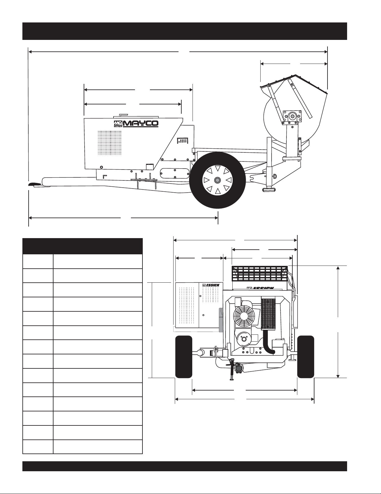
MG-30 PUMP — DIMENSIONS (MG30-M2D MOBILE UNIT)
I
M
L
K
MG30-M2D
.FERSNOISNEMID
A)sretem27.1(.ni0.86
B)sretem82.2(.ni0.09
C)sretem10.1(.ni0.04
D)sretem60.1(.ni0.24
E)sretem218.(
F)sretem00.2(.ni0.97
G)sretem74.1(.ni0.85
H)sretem27.1(.ni0.86
I)sretem43.4(.ni171
J)sretem18.2(.ni111
.ni0.23
J
F
tinUliboMsnoisnemiD.5elbaT
E
G
A
B
D
C
H
K)
L)sretem35.1(.ni5.06
M)sretem569.(.ni83
PAGE 16 — MAYCO MG-30 PUMP — OPERATION AND PARTS MANUAL — REV. #3 (09/15/11)
sretem73.1(.ni0.45
Figure 3. MG-30 (Mobil Unit Dimensions)
Page 17
MG30-2
A
B
C
D
I
E
F
G
H
MG-30 PUMP — DIMENSIONS (MG30-TD2 TAG UNIT)
tinUgaTsnoisnemiD.6elbaT
.FERSNOISNEMID
A)sretem90.1(.ni0.34
B)sretem25.1(.ni0.06
C)sretem678.(.ni5.43
D)sretem81.1(.ni5.64
E)sretem73.1(
F)sretem35.1(.ni5.06
G)sretem34.2(.ni0.69
H)sretem40.3(.ni021
I)sretem292.(.ni5.11
.ni0.45
Figure 4. MG-30 (Tag Unit Dimensions)
MAYCO MG-30 PUMP — OPERATION AND PARTS MANUAL — REV. #3 (09/15/11) — PAGE 17
Page 18

MG-30 PUMP — GENERAL INFORMATION
General
The MAYCO Model MG30-M and MG30T plaster-mortar,
fireproofing pumps are designed to pump material at a steady
rate of flow. This is accomplished with two pistons. One piston
does all the pumping; the other is a
piston is a
which causes the pulsating material from the pumping piston to
be pumped at a steady rate of flow.
Your MAYCO pump has been serviced and test-run at the
factory. Upon delivery and inspection the machine is ready for
operation on the job.
This pump uses a 3-1/2 inch pumping piston and therefore
develops a higher pressure than most concrete pumps. It is
extremely critical that the pump drive components, pumping lines
and components are of the finest quality and maintained in a
manner to prevent accidents. Use only
hoses and couplings.
The MG-30 has been assembled with a
installed at the discharge port on the manifold. NEVER pump
materials unless this (pressure relief valve) mechanism is
installed.
Normally, the 750 psi rated brass cap is used in plaster
applications, whereas the 1,000 psi rated unit is used for higher
pressure applications and fireproofing. The brass cap and ball
should be removed and
to prevent material setting up around the ball.
If material hardens around the ball, it will not be effective as a
relief valve when high pressure develops. Install ball discharge
in downward position. Use the manual relief part of this valve to
relieve line pressure before disconnecting material lines or hoses
Power for the operation of this pump is supplied by a Hatz Model
2M41LZ, 35 H.P. diesel air-cooled engine. This engine transfers
power through a V-belt to a totally enclosed speed reducer and
also operates a twin-cylinder piston type air compressor.
The MG-30 is equipped with an
solenoid
electrically controlled solenoid allows the operator to
stop
When the solenoid valve is energized (i.e. electric current is
applied to the solenoid) the engine speed will increase to the
pre-set governed speed, engaging the
pump. When the solenoid is de-energized, the engine speed
will decrease, returning to idle, disengaging the centrifugal clutch
and pump.
compensation piston
cleaned daily
valve
and
gravity-feed piston oiler system
the pump remotely from the nozzle.
slave piston
and operates in a manner
high pressure
pressure relief valve
, or more often if necessary,
electrically controlled
centrifugal clutch
. The slave
rated
. The
start
and
Located at the rear of the pump is the mixing unit. The drum
batch capacity of this mixing unit is between 3.5 and 4.0 bags.
The mixer section of the pump can be powered by a either a XX
HP Honda gasoline engine, 8.0 HP Hatz diesel or 2.0 HP electric
motor.
Due to the abrasive nature of the materials being pumped, some
parts of the machine are likely to be worn from use more rapidly
than others. It is therefore suggested that spare parts be kept in
ready reserve at the job site to prevent downtime.
CAUTION :
to
whip
or move in a manner that could cause injury to personnel.
When moving hoses from one job site application to another it is
important to walk the entire system and
kinks or sharp bends in the hose, before starting or resumong
.
the pumping operation.
The following definitions will help assist you in understanding
common pump terminology.
Centrifugal Clutch
The centrifugal clutch is designed to slip when the engine speed
drops due to overloading of the pump. This is a safety device to
protect other parts of the machine from damage and to prevent a
buildup of pressure in the material hose. Continued operation of
the machine when the clutch is slipping will cause damage to
the clutch. The clutch needs no adjustment or lubrication.
Pump Head Unit
The pump head unit consists of two pistons--one being the
pumping piston and the other a compensating piston, driven by
the cam and rocker arm principle.
The pump housing is equipped with inlet and outlet valve seats
and two special hard rubber or steel balls. When the piston is
and
retracted, the inlet valve seat opens for intake of material into the
piston chamber; when the piston is extended, the inlet valve
closes and the outlet valve opens, allowing material to be
pumped. There are three sections to the pump head unit.
ALWAYS ASSEMBLE THESE SECTIONS PRIOR TO
MOUNTING PUMP HEAD UNIT ON FRAME, MAKING SURE
THE SEAL RINGS FIT UP AIRTIGHT.
If hoses or lines are
if lines are
pumping cycle, the pump pressure could
straighten out the kink or force out the blockage.
The rapid surge of material could cause the lines
kinked
blocked
when starting up or during
for any reason, or
visually inspect
for any
PAGE 18 — MAYCO MG-30 PUMP — OPERATION AND PARTS MANUAL — REV. #3 (09/15/11)
Page 19
MG-30 PUMP — GENERAL INFORMATION
Main Bearings
The two main crankshaft bearings are sealed bearings. These
bearings should be greased about every two days of pump
operation. Any good lithium base grease is acceptable. Too much
grease cause the bearings to overheat.
Rocker Arm Shaft
The two rocker arms have bronze bearings. These bearings
should be greased
Rod Ends
Each piston rod and connecting rod from the crankshaft has a
roller bearing. Lubricate these four roller bearing daily with lithium
base grease.
NOTE
Cylinders
The cylinder walls do not wear to any degree. Care should be
taken not to damage the surface on the ends of the cylinders as
this will cause an air leak between the end of the cylinders and
the pump housing.
NOTE
every day
of operation.
Daily lubrication of the roller bearings
(except main bearing) will prevent any
dirt and foreign matter from entering the
bearings.
NEVER!
pump. The cylinder bore is
plated
chrome.
use
muriatic acid
to clean the
chrome
. Muriatic acid will dissolve the
The rubber check balls are components of the pump that will
wear quite
high pressure
balls. The rubber check balls can last anywhere from a week to
2 or 3 days depending on the pumping pressure. Jamming the
pump or running the pump at a very high pressure may split the
rubber check balls.
NOTE
Steel Check Ball
Steel check balls are used in
they form a water tight seal at the valve seat. This prevents the
check valve from packing due to separation at the valve.
Leather Piston Cup
The piston, which is held to the push rod by a nut, consists of
several parts made of various materials with close tolerances,
having as the center a
cup is in constant contact with the cylinder and the material and
it wipes clean the cylinder on each stroke, thereby preventing
damage to the cylinder. When the machine is shut down, the
piston cups should be periodically inspected and replaced if
frayed or damaged.
The leather piston cups will outwear the rubber balls. The leather
piston cups as well as the rubber balls can be damaged
prematurely if exposed to
jamming of the pump.
rapidly
and must be replace frequently.
is the main cause of wear to the rubber check
When replacing either rubber check ball,
always
of wear. Make sure the o-rings and
associated parts are clean and free of
dirt when the rubber check valve is
reassembled.
inspect the other ball for signs
fireproofing
applications, because
pre-lubricated leather piston cup
excessive pump pressure
Excessive
. This
or
Leather Piston Lubrication
Pump Housing
There are 3 sections to the pump housing,
housing
are held together with "T" slot bolts and are aligned to each
other with guide rings on the flange surface.
Always assemble these 3 sections into a complete unit before
placing it on the pump. It is important that when the pump housing
unit is placed on the pump that all of the gaskets and o-rings are
aligned properly with an air tight fit.
Rubber Check Ball
Rubber check balls (not steel) are used in
applications, because they form a water tight seal at the valve
seat. This prevents the check valve from packing due to
separation at the valve.
(center), and
MAYCO MG-30 PUMP — OPERATION AND PARTS MANUAL — REV. #3 (09/15/11) — PAGE 19
crossover housing
hopper elbow, main
. These 3 housings
plaster
and
stucco
Due to the close tolerance of the piston to the cylinder, the piston
is equipped with a felt ring to keep the cylinder constantly
lubricated for increased life. The felt ring is lubricated through
the oiler fitting and tubing installed at rear of piston.
The oiler tank is mounted adjacent to the fuel tank. The
should be checked regularly
if necessary, with a good grade of S.A.E. 20W or 30W motor oil.
Oiler tank capacity is 1.5 quarts (.709 liters).
With the engine running, open needle valve (located below oil
tank) very slightly. Oil should flow for approximately 5 minutes
before pumping material. This will allow oil to reach and penetrate
the felt ring. Opening the valve too far will cause oil to flow
excessively. Close the valve when the machine is not in use to
prevent all the oil draining from the tank.
oil level
during operation and tank filled,
Page 20
MG-30 PUMP — GENERAL INFORMATION
O-Rings
O-Rings have been installed at sealing points throughout the
pump head unit. These O-rings act as seals and are very
important for the efficiency of the machine. Great care should be
taken when assembling or disassembling those parts where “O”
rings have been installed. Always clean O-ring groove thoroughly
grease O-ring before installing.
Inspection of O-rings should be made regularly. It should be
done each time a part containing an O-ring has been
disassembled. Carefully remove and check O-ring to see it is
not chipped, broken, peeled or has any other signs of deformity.
If any of these conditions exists, the O-ring should be replaced.
Pump Overloading
If at any time the pump is jammed from separation or a sand
pack in the hose, the clutch on the engine will slip. This will
protect the moving mechanical parts of the pump from being
overloaded and damaged. The capability allows the pump to
shut itself down in the event an operator is not near pump if a
sand pack or jam-up occurs.
When the drive belt is moved from the largest pulley on the
clutch to the smallest, the output power of the pump is increased
by a factor of three. So, when operating the pump at the lower
speed, the RPM of the engine should also be reduced. This will
allow the clutch to slip in the event of a separation or sand pack,
and therefore will safeguard the hoses and the mechanical
working parts of the pump from damage.
USE ONLY "O-RINGS" OBTAINED
NOTE
Valve Seats
The valve seats are a loose fit in the pump housing. There are no
set screws holding them in place. When the valve seat has been
worn to a point where a
the valve seat (keeping the ball from seating properly), the valve
seat should be replaced.
Sand Packs
Washed sand left in the material hose can cause a sand pack
(clog) in the hose. When the material hose is washed out, make
sure all of the loose sand is washed out of the hose. If loose sand
is allowed to remain in the hose, the new material coming through
the hose will push the sand ahead until it forms a clog in the
hose.
Separation
Separation in the pump or the material hose is caused by water
being forced out of the material through a loose connection.
Make sure that none of the gaskets or o-rings in the pumping
system leak. Loose hose connections are one of the most
common causes of separation.
Whenever water leaks out through a hose connection, the
material will build up slowly. In an hour or so, depending on how
bad the leak, a restriction will form at the connection causing the
pump to work much harder to force the material through the
restriction. This also slows down the output production of the
pump. If this condition is not corrected, the pump will jam and
stop.
FROM THE FACTORY
manufactured of a special hardened
rubber to meet this specific application.
new
rubber check ball strikes the bar in
, as they are
NOTE
hoses when the pumping of stiff materials is required. Make sure
that all hoses are in good condition and that all connections are
air tight. When using the lower pumping speeds, run the engine
at a lower speed.
Leaks
Water can become separated from the material being pumped.
This is usually caused by loose connections or damaged seals.
When separation occurs, a restriction caused by a buildup of
material around the leak forces the pump to work harder. As a
result, pump output is lowered and eventually the pump will
stop.
Hose and Fittings
Due to the high pressure which the machine is capable of
producing we recommend the use of specially constructed
MAYCO hose. This hose has been designed to withstand the
pressures required to pump the material.
MAYCO hoses are available in 25 ft. and 50 ft. lengths. Each size
is equipped with a male insert on each end.
It is suggested to use all 2-inch (5.08 cm.) hose with the exception
of the last 25 or 50 ft. This should be 1.5 inch (3.81 cm.) hose, to
be used as a whipline.
Wheels
The machine is equipped with
rotating on tapered roller bearings. These bearings have been
packed at the factory and need not be repacked for approximately
6 months, at which time they should be removed, cleaned and
repacked with a good grade of wheel bearing grease.
Operating the pump at lower speeds
(placing the drive belt in either of the two
pulley groves next to the engine) will
develop high pressure in the material
pneumatic (air) type wheels
,
PAGE 20 — MAYCO MG-30 PUMP — OPERATION AND PARTS MANUAL — REV. #3 (09/15/11)
Page 21
MG-30 PUMP — GENERAL INFORMATION
Reducers
sizes of hose.
Air Compressor
Your plaster and mortar pump is equipped with a piston type
Quincy Air Compressor
This air compressor supplies air to the nozzle for spraying of
material.
Factors Affecting Hose Pressure
Stiffness of the mix is the most important factor affecting hose
pressure. There are others, however, that can be equally
important.
1. Hose Length – Pressure varies directly with the length of
2. Hose Size – The pressure required to pump material
3. Gypsum – In using gypsum plaster a rich mix (such as
4. Binders – Some binders for plaster take more pressure
5. Aggregates – The most familiar types of aggregate are
and
unions
NOTE
the hose. The pump must develop twice as much pressure
with a 100-ft. length of hose as it does with a 50-ft. length.
through a hose varies with the area of the hose. Thus, if the
pressure required for a length of 2-inch diameter (5.08 cm.)
hose is 300 pounds (136 Kg.), the pressure required for
the same length of 1.5-inch diameter (3.81 cm.) hose would
be over 500 pounds (227 Kg.) using the same pumping
rate.
2:1) will take more pressure to pump than a leaner mix. In
a 2:1 mix you will probably have to make your mix
somewhat softer than a 3:1 mix.
than others. A plaster using gypsum will require the most
pressure. Portland Cement pumps quite easily with a
minimum of pressure, as does clay or lime.
sand, vermiculite, perlite
has its own characteristics. As most sand absorbs very
little water, it is the easiest with which to control the
consistency of materials.
other hand, absorb considerably
under pressure, as do most perlites. Therefore, in the latter
cases, whether the binder is gypsum or
your mix must be somewhat softer.
NOTE
are available for connecting the various
Connecting material hoses by means of
any type of quick coupling device is
recommended because they generally
do not have an adequate pressure rating
and are hazardous.
, driven by V-belts from the engine.
and
zonolite
vermiculite or zonolite, on the
. Each one of these
more water
when pumped
Portland Cement
All materials being pumped become
stiffer, when applied under pressure.
Therefore, the mix at the machine must
be softer than if it were taken from the
mixer for hand application.
Effect of Hose Pressure On Height
When elevating a plaster containing gypsum and light weight
aggregate add about one-half pound per square inch to the
not
required horizontal pump pressure for every foot you elevate the
nozzle above the Mayco Model MG-30 plastering unit. This
additional pressure is generally not serious because you will
probably be running between 1 and 2 lbs. per square inch per
foot to overcome friction in the hose.
.
As an example, if you were using a 40 ft. (12 meters) hose with a
pressure of 1-1/2 psi per foot or a total of 60 psi when plastering
a wall, and you sprayed a 20 ft. (6 meters) ceiling, you would only
increase the pressure 10 lbs. (4.53 Kg.) or have a total of 70 lbs. (32
Kg.) pump pressure. If you wanted to spray a 40 ft. (12 meters)
ceiling and needed another 40 ft. (12 meters) of hose, your pump
pressure would be:
NOTE
Nozzle
The MAYCO spray nozzle is constructed of a lightweight material.
It has been designed with a removable cap for changing to various
size orifices and is also equipped with an atomizer for variance
in spray patterns.
The output from the spray nozzle can be controlled to supply a
volume from zero to 4.5 cu. ft. per minute. Because of this
considerable range in volume, the orifice in the nozzle must be
changed to fit the desired volume in order to obtain a good pattern.
In most cases a 5/8-inch (1.58 cm.) orifice will give a good pattern
in most browning or scratching applied to paperback wire. On
metal lath you should use as large an orifice as possible and
lower the air pressure. In most cases the air jet should be set
,
back from the orifice 1/2 to 5/8 inch (1.27 to 1.58 cm.). You will
find an air valve at the nozzle to control the air pressure.
First 40 feet @ 1-1/2 psi/ft. .............60 psi
Second 40 feet@ 1-1/2 psi/ft. ......... 60 psi
Elevation pressure 40 psi/2 ........... 20 psi
Total pump pressure .......140 psi
Material hose, steel delivery line and
couplings are available in various
pressure ratings when
and
tear
wear
calculated pressure rating.
will reduce the above
new. Age
MAYCO MG-30 PUMP — OPERATION AND PARTS MANUAL — REV. #3 (09/15/11) — PAGE 21
Page 22
MG-30 PUMP — GENERAL INFORMATION
To change from a fine texture to a heavy browning pattern, follow
these steps:
1. Lower the air pressure.
2. Change to a larger size orifice.
3. Set the air jet farther back from the orifice.
4. Increase the volume of material.
To increase nozzle frequency and obtain small plaster globules,
reverse the above procedure.
How the Nozzle Operates
With the machine running at a rate to brown 80 square yards 1/2"
thick, you should use a 1/2-inch (1.27cm.) orifice and the distance
from the air stem to the orifice would be 3/8-inch (.952 cm.). To
scratch metal lath at the same pumping speed, you would set the air
stem from 1/2 to 5/8-inch (1.27 to 1.58 cm.) from the orifice, and you
would probably use a 5/8-inch (1.58 cm) orifice.
When adjusting the air pressure, it is desirable to get a good
even pattern in the spray. If the air pressure is too high, the plaster
will rebound from the wall. If the air pressure is too low, the spray
pattern will be very narrow and plaster cannot be sprayed on
‘evenly. Adjust air pressure at nozzle to obtain the desired pattern.
Since the operator feels little or no pulsation when running the
Mayco Model MG30 plastering unit, it would appear that plaster
comes from the nozzle in a steady stream. Actually, in operation,
a globule of plaster comes from the nozzle and is then followed
by a globule of compressed air.
ESSICK MIXER
The Essick Model EM120SM
shipped completely assembled and has been factory tested.
The drum batch capacity of these mixers is between 3.5 and
4.0 bags. With proper care, they will give continuous service
year-after-year.
This mixer is powered by a
engine. The power from the engine is transmitted via a clutch/
reduction assembly that is coupled directly to the paddle shaft.
Therefore providing high mixer torque and eliminating V-belts .
BEFORE STARTING
Before starting the engine, read the engine
owners manual and thoroughly understand the
safety information.
OIL LEVELS
Be sure to check the oil levels in the engine and transmission
before starting the mixer.
DIESEL ENGINE CARE
For care and operation of either
engine manufacturer’s operating instructions furnished with the
engine. We recommend draining and refilling the engine
crankcase at least every thirty hours of operation. Check the
engine oil level daily.
plaster
HATZ
HATZ
and mortar mixer is
Model 1B30, 8.0 HP
diesel engine, refer to the
diesel
The Mayco nozzle can be operated with as few as 50 plaster
globules per second, or a frequency of 50 cycles per second,
and as high as 1,000 cycles per second with the pump operating
at a constant volume.
When the nozzle is emitting 50 plaster globules per second,
each globule is 20 times the size of the plaster globules emitted
when the nozzle is set for 1000 plaster globules per second.
Here lies the basis for the various applications of the Mayco
Model MG30.
For example, when a fine texture is desired, the nozzle should
operate at a high frequency to break the plaster up into small
particles. In scratching metal lath, it is desirable to produce large
plaster globules that will adhere to the metal lath. Difference in
frequency can be detected by the sound of the nozzle in
operation. When the sound at the nozzle is high, almost at a
scream like pitch, the frequency is high and the globule size is
small.
PAGE 22 — MAYCO MG-30 PUMP — OPERATION AND PARTS MANUAL — REV. #3 (09/15/11)
Page 23
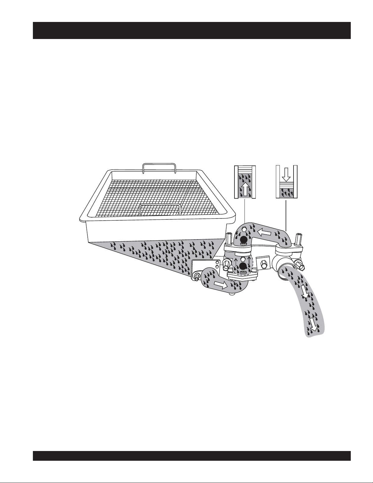
How It Works
MG-30 PUMP — APPLICATION
Mayco Plaster Pump,
The
materials at a steady rate of flow. This is done by using two
cylinders. The crank powered pumping cylinder does all of the
pumping. The cam powered slave cylinder is a compensating
cylinder and operates in a manner which causes the pulsating
material from the pumping cylinder to be pumped at a steady
rate of flow. The slave cylinder will not move until enough pressure
is developed to produce this steady rate of flow.
Model MG-30 designed to pump
As shown in Figure 5, the pumping cylinder retracts drawing
the material past the ball A and filling the cylinder. The slave
cylinder is pumping the material out to the nozzle and
causing ball
to the pumping cylinder intake.
HOPPER
B
to seat
PUMPING
CYLINDER
INTAKE
preventing the material from returning
B
SLAVE
CYLINDER
INTAKE
A
DISCHARGE
Figure 5. Pumping Cylinder (Discharge)
MAYCO MG-30 PUMP — OPERATION AND PARTS MANUAL — REV. #3 (09/15/11) — PAGE 23
Page 24
MG-30 PUMP — APPLICATION
The pumping cylinder (Figure 6) is forcing the material past
ball B and out to the nozzle, also
material will not flow back to the hopper. This action also
fills the slave cylinder for the next stroke.
seating ball
A so that the
NOTE
HOPPER
PUMPING
CYLINDER
PUMPING
B
The slave piston will not move until
enough pressure is developed to
produce a steady rate of flow.
SLAVE
CYLINDER
INTAKE
A
N0
DISCHARGE
Figure 6. Pumping Cylinder (No Discharge)
PAGE 24 — MAYCO MG-30 PUMP — OPERATION AND PARTS MANUAL — REV. #3 (09/15/11)
Page 25
MG-30 PUMP — APPLICATION
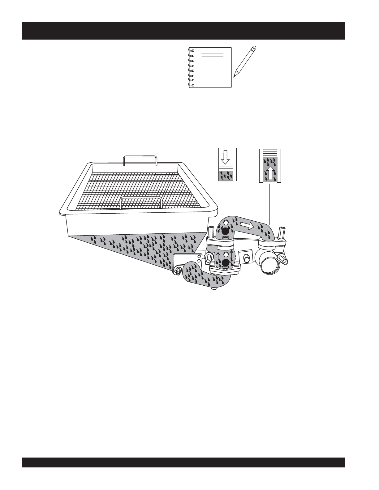
Pressure Relief Valve (Automatic)
Purpose
To provide the capability that will
pressure in a material hose or line whenever the flow of material
is restricted for any reason, causing unsafe pressure to build up
in the hose or line.
Safety Valve Placement (Automatic)
Place the automatic safety valve at the outlet side of the plaster
pump, ahead of the hose connection. This automatic safety valve
is to be used in conjunction with the manual release mechanism
(
safety relief pressure plug
Theory of Operation
Located on the
(Figure 7), is a pipe nipple with an opening which is sealed off
with a rubber ball that is held against the opening with a
cap
.
It is the responsibility of the pump operator to ensure that the
delivery hose and line system with all clamps and accessories
have a higher pressure rating than the safety cap being used.
bottom
of the
automatically
).
release the
safety relief pressure valve
brass
NOTE
NOTE
Suggestion:
DO NOT use a 1000 psi cap if your pumping requirement is less
than 750 psi.
system pressure.
The rubber ball will stay in place until an excessive amount of
pressure occurs that will cause the ball to
opening (Figure 8) in the brass cap and release the pressure in
the hose or line.
Always
NEVER place the MG-30 into
operation without a safety relief
pressure valve with a manual
release control installed on the
pump discharge.
ALWAYS
safety valve
prevent the ball from striking
someone and possibly causing
injury.
use a cap that is rated less than the total
point the brass cap on the
downward
blow
. This will
out through the
Figure 8. Safety Relief Pressure Valve
(Rubber Check Ball Release)
Figure 7. Safety Relief Pressure Valve
(Automatic Mode)
MAYCO MG-30 PUMP — OPERATION AND PARTS MANUAL — REV. #3 (09/15/11) — PAGE 25
Page 26
MG-30 PUMP — APPLICATION
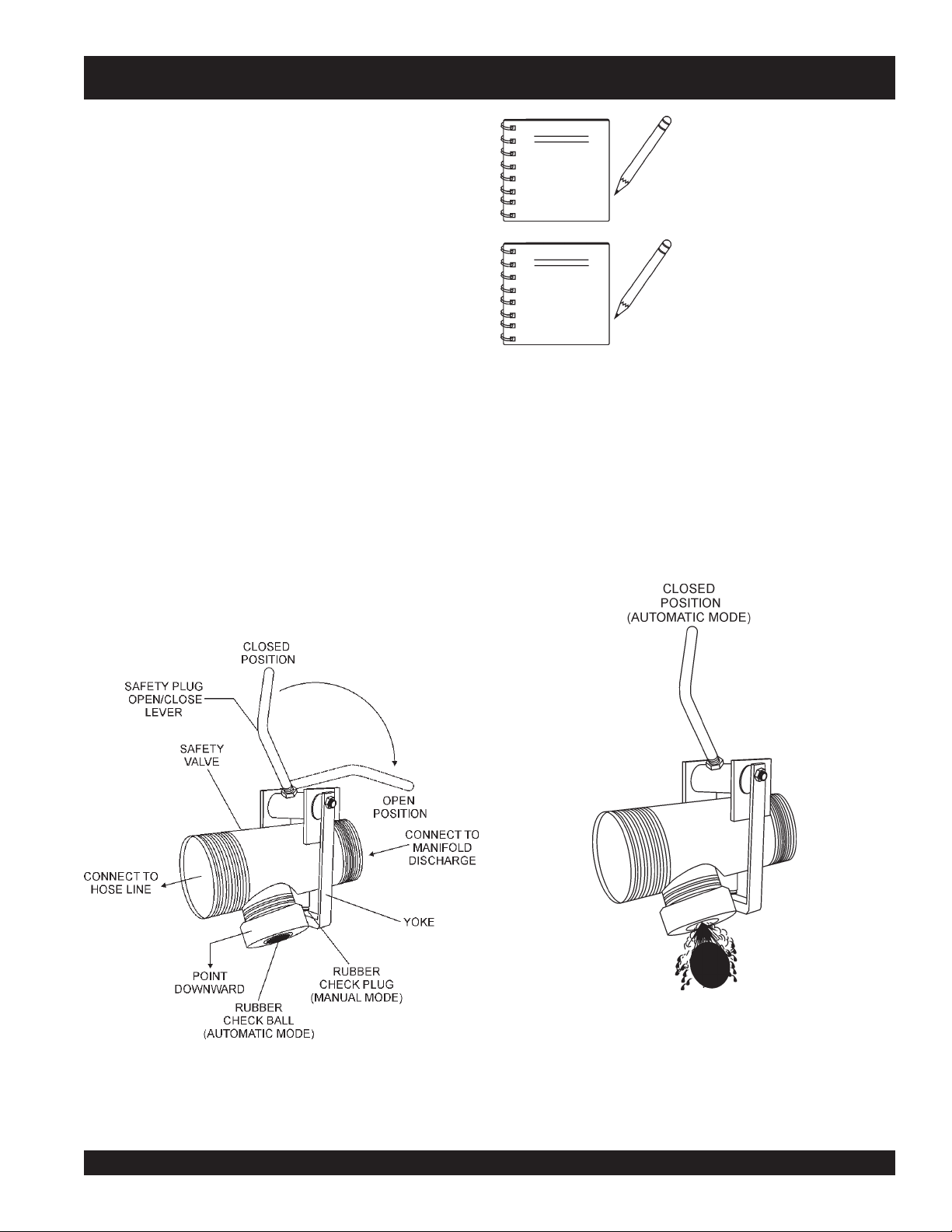
Pressure Relief Plug (Manual Operation)
Purpose
To provide the capability that will
in a material hose or line whenever the flow of material is restricted
for any reason, causing unsafe pressure to build up in the hose
or line.
Safety Valve Placement (Manual)
Place the
discharge side of the plaster pump, ahead of the hose connection.
Located on the pressure relief valve is a
release plug
a steel clamp (
downward
This manual pressure release plug is to be used in conjunction
with the automatic release mechanism (
safety relief pressure valve
(manual activation), the plug is held in position by
yoke) and is
to release the pressure in the system.
manually
activated by pulling the lever
ALWAYS
NOTE
release plug before disconnecting
any part of the delivery hose, line or
clamp system.
release the pressure
(Figure 9) at the
rubber pressure
rubber check ball
open the manual pressure
Before activating the manual pressure release
must
do the following:
1. Stop the engine.
2. Warn all workers and bystanders to stand at least 20 feet
away from the pump and turn their heads away from the
pressure relief safety valve.
3. The operator shall position himself/herself beside the
pressure relief safety valve with his/hers back to the
pump.
4. Wearing safety glasses, reach down with one hand, grasp
the release lever on top of the safety valve.
5. Turn head away from the pressure release plug and lift lever
upwards (open)
6. Remain facing away from the pressure relief valve until
).
counting up to 20, slowly. By that time, the material ejecting
under pressure will be slowly discharging. Work can resume
only after the material has been discharged for a minimum
of 20 seconds.
7. After correcting the problem that caused the excess pressure
in the system line, close the safety plug by pushing the plug
open/close lever
ing.
.
downward (
closed), and resume pump-
plug
the operator
Anytime it is necessary to uncouple or remove any part of
the delivery system, the manual pressure release plug must
be opened to relieve pressure in the system.
Figure 9. Rubber Safety Relief Pressure Plug
PAGE 26 — MAYCO MG-30 PUMP — OPERATION AND PARTS MANUAL — REV. #3 (09/15/11)
Page 27
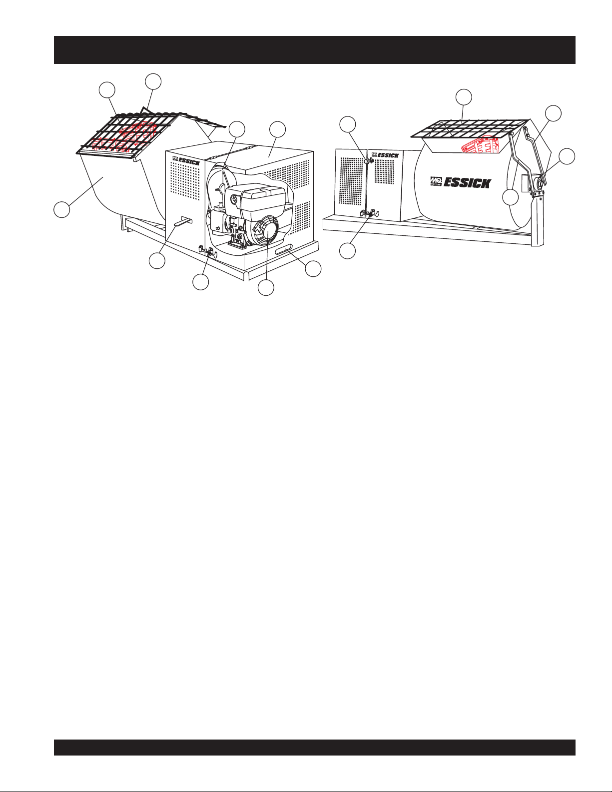
MG-30 PUMP — MIXER MAJOR COMPONENTS
2
1
3
4
8
7
5
5
6
12
7
Figure 10 illustrates the major components and controls of
the mixer.
13
9
10
11
Figure 10. Mixer Major Components
1. Mixing Drum — Made of
steel
. Mixing materials such as
8. Clutch Lever — Push the clutch lever
concrete, mortar, plaster are to be placed into this drum for
mixing. Always clean the drum after each use. Drum
capacity is 12 cu. ft.
2. Mixing Paddles — Used in the mixing of material. This
9. Dump Handle — Pull this handle downward to dump the
unit uses four different types of paddles to provide a fast
uniform mix.
3. Bag Cutter— This feature allows compound mixing bags
10. Pivot Point/Zerk Fitting — There is, on each end of the
to be opened easily, therefore allowing the contents of the
bag to fall directly into the mixing drum. Bag capacity is 3.5
to 4 bags.
4. Transmission — Totally inclosed oil bath transmission.
12. Safety Grill Lock Handle — To prevent injury to hands
5. Engine Cover — Lift this cover to gain access to the engine
and transmission compartments.
6. Engine — The mixer unit is powered by a Hatz Model
IB30, 8.5 HP
diesel
engine. See page 30 for engine
component definitions.
13. Safety Grill — Provided for operator safety. This safety grill
7. Engine Cover Grip — Place hand inside grip then lift
upwards to raise cover. When lifting of the cover is required
make sure both rubber bunjee latches have been released.
8. Rubber Latch — Use this latch to secure the engine
compartment cover.
forward
, toward
the tow (tongue) end of the mixer to engage clutch. Once
clutch is engaged paddle shaft will rotate. To disengage
clutch pull the clutch
backwards
towards the engine.
contents of the drum. Push the handle upward to return the
drum to its vertical position.
mixing drum a zerk grease fitting. These fittings lubricate
the dumping mechanism. Lubricate both fittings at least
twice a week.
and arms, the safety grill should ALWAYS be locked when
the mixing of plaster or mortar is required. Also when
transporting the mixer the safety grill should be locked. The
safety grill should only be un-locked when cleaning of the
blades and drum is required.
is designed to keep hands and solid objects out of the
mixing drum when in use. This grill should be closed at all
times when pump is in use. DO NOT remove the grill or
grill opening bar. Keep the grill clean by washing it down
daily.
MAYCO MG-30 PUMP — OPERATION AND PARTS MANUAL — REV. #3 (09/15/11) — PAGE 27
Page 28
MG-30 PUMP — MG30 M2D MAJOR COMPONENTS
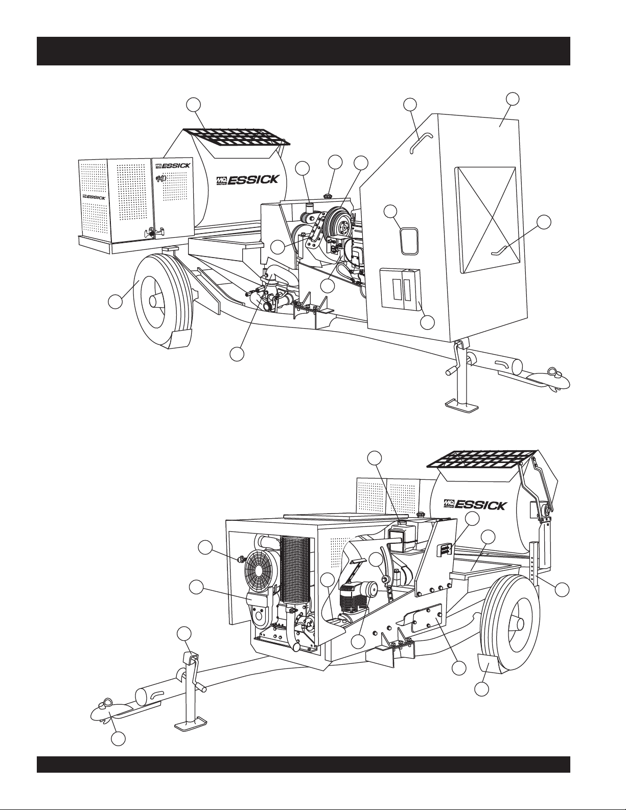
Figure 11 illustrates the major components and controls of
the MG-30 (Mobil Unit).
2
3
4
12
5
13
6
MG30-M2D
7
9
11
8
10
1
Figure 11. MG-30 Major Components
22
23
24
14
15
16
19
20
17
21
18
26
25
PAGE 28 — MAYCO MG-30 PUMP — OPERATION AND PARTS MANUAL — REV. #3 (09/15/11)
Page 29

MG-30 PUMP — MG30-M2D MAJOR COMPOUNDS
1. Manifold — Cast steel manifold, 2 in. (5.08 cm.) for plaster,
3 inch (7.62 cm.) for fireproofing. This manifold is designed
with a
manual pressure relief valve
safety pressure relief valve
2. Tires — This trailer uses two ST205-750 x14C type tires.
Tire inflation pressure is the most important factor in tire
life. Pressure should be checked to
operation. DO NOT bleed air from tires when they are hot.
Check inflation pressure weekly during use to insure the
maximum tire life and tread wear.
3. Mixer — This unit uses a "
and
plaster mixer
definitions.
4. Oiler — Cam bearing oiler. Fill with SAE 20 or 30 wt. motor
oil. Lubricates cam surface.
5. Fuel Gauge/Fuel Cap — Read the top of this cap to
determine if the fuel level is low. If fuel level is low, remove
cap to add #2 diesel fuel.
6. Gear Reduction Pulley — This is an adjustable 4-groove
pulley. Select the pulley speed that fits your pumping
requirement.
. See page 27 for mixer component
rated between 700-1000 PSI.
Essick
and an
automatic
50 psi cold
" mechanical 12 ft3
before
mortar
14. Piston Oiler Tank— Fill this tank to the "
15. Lubrication Port Panel — Central grease panel. All
16. Hopper — This unit uses a galvanized hopper which can
17. Mixer End Jack Stand – Use this jack stand to level
18. Lubrication Box Access Cover – There are four access
19. Gear Reduction Adjustment Bolt – Loosen this bolt to
20. Battery – This unit uses a +12 VDC type battery.
FULL
" level for
normal operating conditions. Check regularly. Fill with SAE
30 wt. type motor oil. Oiler tank capacity is 1-1/2 quarts (1.14
liters).
lubrication points can be accessed via this panel. Allows
lubrication of all bearings without lifting the hood.
hold up to 12.0 cu. ft. (340 liters) of mix. NEVER put hands
or any other parts of you body into the hopper.
and support the pump.
covers on the pump. Remove these doors to gain access to
drive and piston assemblies when maintenance is required.
pivot the gearbox assembly upwards or downwards. This
will allow for the placement of the V-belt on one of the four
pulley grooves.
ALWAYS
use gloves and eye protection when handling the battery.
7. Compartment Hood Lift Handles — There are two
compartment hood lift handles located on each side of the
hood. Grip handle and pull upwards to lift hood.
8. Compartment Hood — This hood encloses the engine,
compressor, gear reduction pulley, reduction gearbox,
battery, control box and other associated components
required to operate the pump.
with the hood in the up position.
9. View Access Window — This opening allows the user to
start the unit and have access to the control box without
lifting the compartment hood.
10. Access Cover/Handle — Turn this handle clockwise to
release latch, then lift upwards. When this cover is in the
open position it will provide a more free flow of air to help
keep the engine and associated components cool.
11. Documentation Box — Contains information regarding
the pump and mixer.
12. Speed Reduction Gearbox — A constant-mesh type and
total enclosed gearbox with all gears immersed in oil. Fill
with SAE 90 wt. motor oil.
proper operating level.
13. Engine Control Box — Contains the engine ignition
switch, operation switch, engine status LED's (5), hour meter,
remote control connector and 25 amp fuse.
NEVER!
ALWAYS
operate the pump
keep gearbox oil at
21. Air Compressor – This unit uses a piston type
22. Throttle Control Knob – This is a variable speed type
23. Engine – This unit uses a
24. Tow End Jack Stand – Use this jack stand to level and
25. Tow Hitch Coupler – Requires a 2-inch ball hitch or a
26. Chock Blocks – Place these blocks (not included as
Quincy
Air Compressor
air compressor supplies air to the nozzle for spraying of
material. The compressor has an output of 10 CFM @ 100
psi. A weekly check should be made of the crankcase oil
level to make sure it is at the
the two marks on the dipstick.
control. Turning the throttle lock (CCW) left unlocks the
throttle allowing the throttle control cable to be pulled out to
the desired position. Once the desired throttle position
(speed) has been achieved, turning the throttle lock to the
(CW) right locks it in place. Use the fine tune adjustment
knob to fine tune the engine rpm's.
To place the engine in idle, press the top button inward all
the way.
cooled diesel engine. See page 31 for engine component
definitions.
support the pump.
pin. Capable of towing 5,000 lbs.
part of your concrete pump package) under each wheel
to prevent rolling or when parked on a slope.
, driven by V-belts from the engine. This
full mark
HATZ
, or at least between
Model 2M4LZ, 35 HP air
MAYCO MG-30 PUMP — OPERATION AND PARTS MANUAL — REV. #3 (09/15/11) — PAGE 29
Page 30
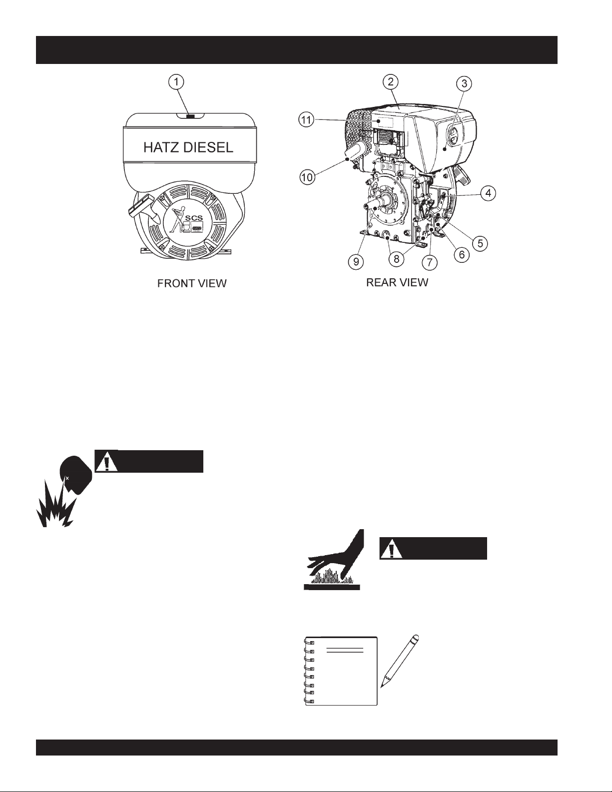
MG-30 PUMP — HATZ 8.5 HP ENGINE COMPONENTS
Figure 12. Hatz Model 1B30 8.5 HP Diesel Engine
INITIAL SERVICING
The
mixer's
lubrication and filled with fuel prior to operation. Refer to the
manufacturers Engine manual for instructions & details of operation
and servicing.
1. Fuel Filler Cap/Fuel Tank – Pull this latch to add
fuel to the tank. After refueling, always make sure the fuel
cap is latched properly. DO NOT over fill. For additional
information refer to engine owner's manual.
engine (Figure 12) must be checked for proper
diesel
WARNING
Adding fuel to the tank should be accomplished only
when the engine is stopped and has had an
opportunity to cool down. In the event of a fuel spill,
DO NOT attempt to start the engine until the fuel residue has been
completely wiped up, and the area surrounding the engine is dry.
2. Engine Lifting Straps/Cover – Remove the air cleaner
cover, then lift this cover (the one with decals on it) to gain
access to the engine lifting straps.
3. Air Cleaner/Cover – Prevents dirt and other debris from
entering the fuel system. Remove wing-nut on side of air
filter cover to gain access to filter element.
4. Speed Control Lever – This lever is connected to the
throttle control which is located on the side of the engine
compartment cover. Use this lever to control engine speed.
5. Dip Stick – Remove dipstick to determine if the engine oil
level is low. If low add oil as specified in Table 4, page 14.
6. Engine Motor Mounts – Attach these engine mounts to
the mixer frame. Tighten securely.
7. Oil Filter – Remove this bolt to gain access (internal) to the
engine oil filter. Service the oil filter as recommended in the
maintenance section of this manual.
8. Oil Drain Plugs – There are two oil drain plugs, one is
underneath the flywheel, the other on the side of the engine.
Remove these plugs to drain engine oil from the engine
crankcase.
9. Crankshaft – Connect this shaft to the input of the
transmission.
10. Muffler – Used to reduce noise and emissions.
11. Nameplate – Contains information about the engine.
while the engine is running or immediately after operating. NEVER
operate the engine with the muffler removed.
NOTE
WARNING
Engine components can generate extreme heat.
To prevent burns, DO NOT touch these areas
Operating the engine without an
air filter, with a damaged air filter,
or a filter in need of replacement
will allow dirt to enter the engine,
causing rapid engine wear.
PAGE 30 — MAYCO MG-30 PUMP — OPERATION AND PARTS MANUAL — REV. #3 (09/15/11)
Page 31

MG-30 PUMP — HATZ 35 HP ENGINE COMPONENTS
Figure 13. Hatz Model 2M41LZ 35 HP Diesel Engine
INITIAL SERVICING
The
pump's
lubrication and filled with fuel prior to operation. Refer to the
manufacturers Engine manual for instructions & details of operation
and servicing.
1. Muffler – Used to reduce noise and emissions.
touch the muffler while it is hot! Serious burns can result.
NEVER
2. Dip Stick – Remove dipstick to determine if the engine oil
level is low. If low add oil as specified in Table 8, page 37.
3. Speed Control Lever – This lever is connected to the
throttle control which is located on the side of the engine
compartment cover. Use this lever to control engine speed.
4. Oil Filter – Prevents dirt and other debris from entering the
engine. Service the oil filter as recommended in the
maintenance section of this manual.
engine (Figure 13) must be checked for proper
NEVER
operate the engine with the muffler removed.
5. Side Oil Drain Plug – Remove this plug to drain engine
oil from the engine crankcase. For best results drain engine
oil when oil is warm.
6. Air Filter/Cover – Prevents dirt and other debris from
entering the fuel system. Release the latches on the side of
the air filter cover to gain access to filter element.
7. Starter/Solenoid – This engine uses a 12 VDC , 2.7kW
(3.7 HP) starter motor with solenoid.
8. Front Oil Drain Plug – Remove this plug to drain engine
oil from the engine crankcase. For best results drain engine
oil when oil is warm.
9. V-Belt Cover – Remove this cover to gain access to the Vbelt. When replacing V-belt , use only recommended type
V-belt.
MAYCO MG-30 PUMP — OPERATION AND PARTS MANUAL — REV. #3 (09/15/11) — PAGE 31
Page 32

MG-30 PUMP — PRE-INSPECTION (MIXER )
Blade Check
Adjust paddles as shown in Figure 14. Make sure paddle blades
are adjusted correctly before using mixer. Replace all
or
damaged
blades immediately.
defective
Figure 14. Paddle Blade Adjustment, Steel Drum
PAGE 32 — MAYCO MG-30 PUMP — OPERATION AND PARTS MANUAL — REV. #3 (09/15/11)
Page 33
CAUTIONCAUTION
CAUTION
CAUTIONCAUTION
NEVER operate the mixer in
a confined area or enclosed
area structure that does not
provide ample
free flow of air
.
MG-30 PUMP — PRE-INSPECTION (MIXER)
ALWAYS wear approved
protection before operating the mixer.
NEVER place hands or feet inside the mixing
ALWAYS
drum.
on the mixer is locked while the engine is
running. ALWAYS shut-down the engine
before performing any kind of maintenance
service on the mixer.
Before Starting
1. Read safety instructions at the beginning
of manual.
2. Clean the
ticularly the engine cooling air inlet, and air filter.
3. Check the
replace air filter with a new one as required.
make sure the
entire mixer
air filter
eye
and
hearing
safety grill
, removing dirt and dust, par-
for dirt and dust. If air filter is dirty,
Figure 15. Adding Diesel Fuel
ENGINE OIL
1. Remove the engine oil dipstick from its holder (Figure 16).
4. Check fastening nuts and bolts for tightness.
See Figure 12, page 30 for the location of any control or
component referenced in this section.
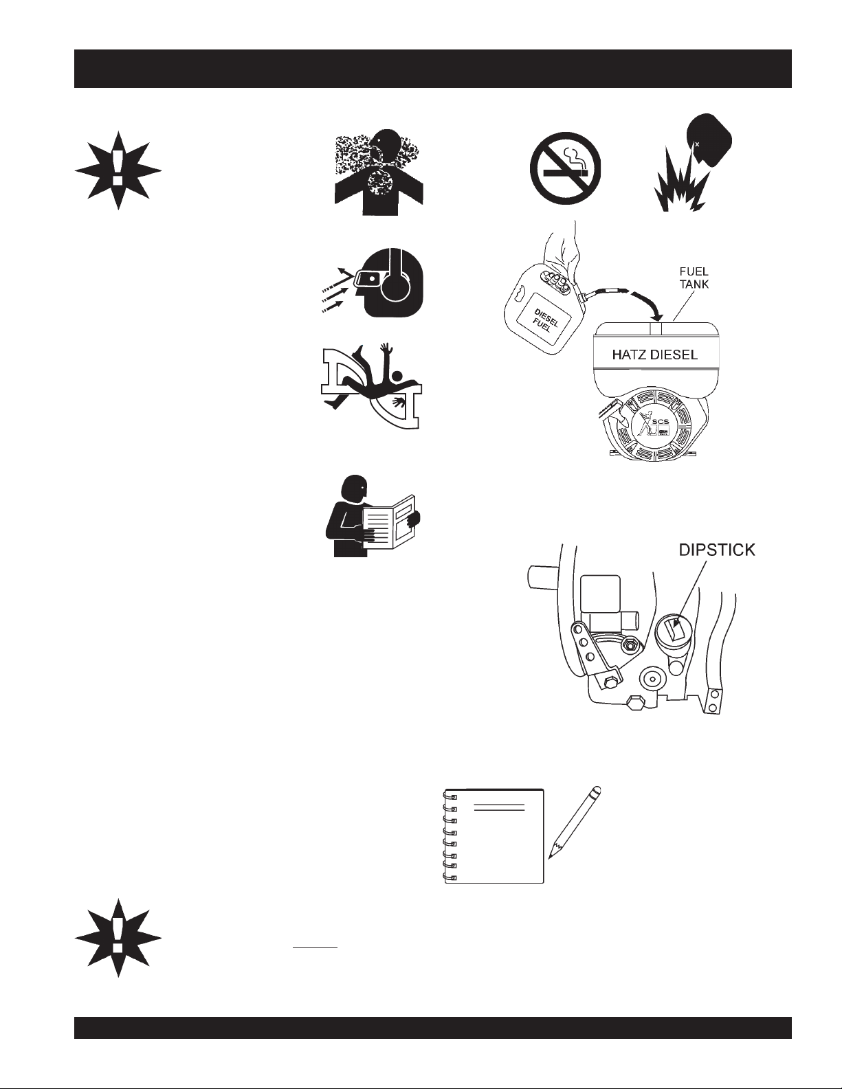
FUEL
1. Lift the fuel cap latch located on top of the fuel tank then look
inside the tank and determine if the mixer's engine fuel is
low . If fuel is low, fill with
Table 4 for other types of recommended fuel.
#2 diesel fuel
(Figure 15). See
NOTE
CAUTION:
Handle fuel safely. Motor fuels are highly
flammable
mishandled. DO NOT
DO NOT attempt to refuel mixer if the engine is
hot or running.
before refueling.
MAYCO MG-30 PUMP — OPERATION AND PARTS MANUAL — REV. #3 (09/15/11) — PAGE 33
and can be dangerous if
smoke
ALWAYS
while refueling.
allow engine to
cool
Figure 16. Oil Filler Port/Dipstick
Reference manufacturer engine
manual for specific servicing
instructions.
Page 34
MG-30 PUMP — PRE-INSPECTION (MIXER)
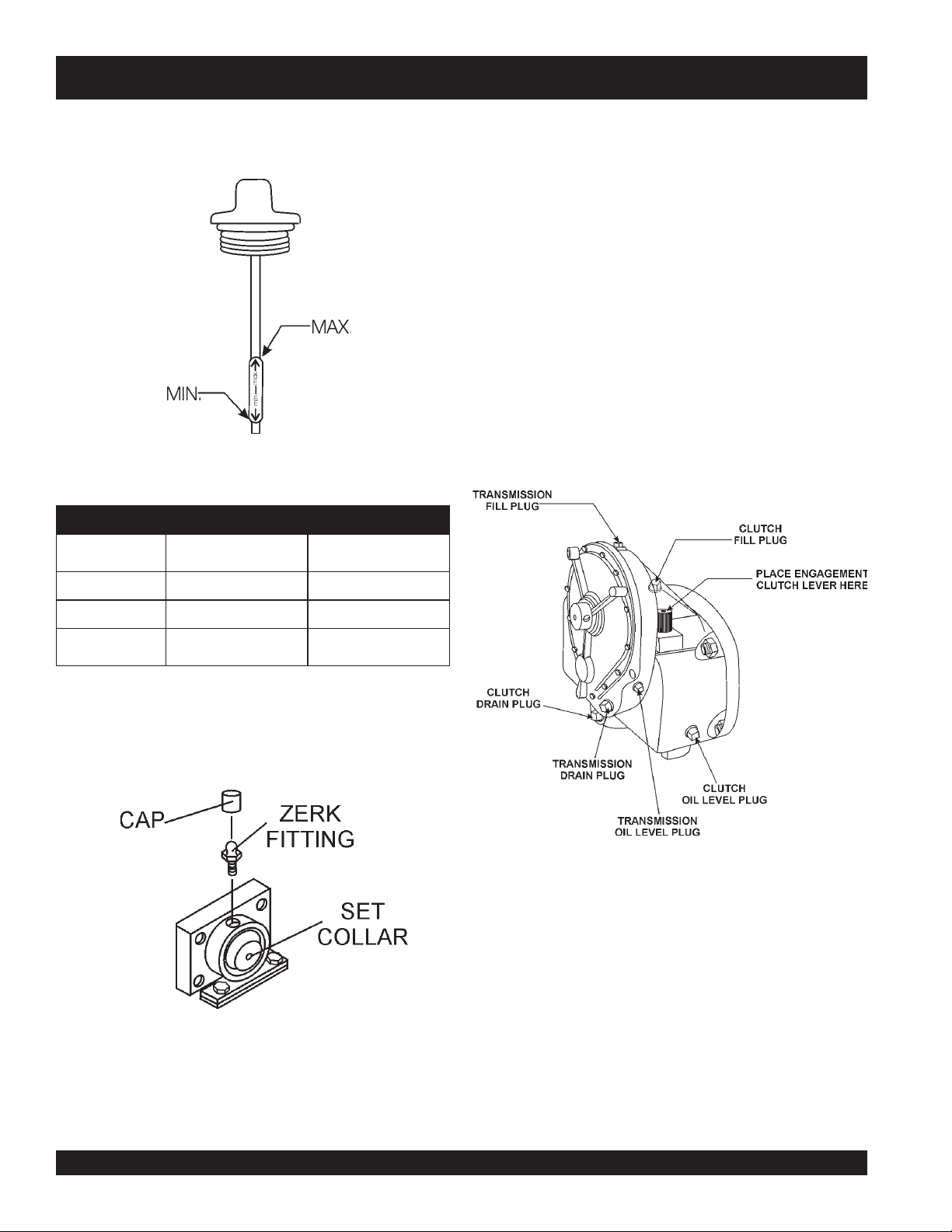
2. Determine if the mixer engine oil is low (Figure 17), add
correct amount of engine oil to bring oil level to a normal
safe level. See Table 7 for recommended oil type.
LUBRICANTS
CLUTCH OIL
1. Remove the clutch oil level plug (Figure 19). If oil begins
to seep out as the plug is being removed, then it can be
assumed that the clutch oil is at the proper operating level.
2. If oil does not seep out as the oil level plug is being removed,
then remove the clutch oil fill plug and fill with SAE 30
engine oil to the proper operating level.
GEAR REDUCTION OIL (TRANSMISSION)
1. Remove the transmission oil level plug (Figure 19). If
oil begins to seep out as the plug is being removed, then it
can be assumed that the transmission oil is at the proper
operating level.
2. If oil does not seep out as the oil level plug is being removed,
then remove the transmission oil fill plug and fill with
Figure 17. Dipstick (Mixer Engine)
edarGliOrotoM.7elbaT
nosaeSerutarepmeT
remmuSrehgiHro)F°77(C°5203-W01EAS
liOrotoMfoedarG
)ssalcSMnahtrehgih(
SAE 90 transmission oil to the proper operating level.
llaFgnirpS)F°05(C°01~
retniW
)F°77(C°5202/03-W01EAS
)F°23(C°0
rewoLrO
01-W01EAS
W5EAS
ZERK GREASE FITTINGS
1. Check the zerk grease fittings at each end of the mixing
drum (Figure 18). These grease fittings lubricate the
dumping mechanism. If the dumping handle is stiff or hard
to move lubricate these fittings.
Figure 18. Zerk Fittings (Bearings)
Figure 19. Transmission/Clutch Lubrication
PAGE 34 — MAYCO MG-30 PUMP — OPERATION AND PARTS MANUAL — REV. #3 (09/15/11)
Page 35

MG-30 PUMP — INITIAL START-UP (MIXER MOBIL ONLY)
WARNING!!
STAND
CLEAR
OF DUMP
HANDLE
Push
This section is intended to assist the operator with the initial
start-up of the
ESSICK
Model EM120SM mixer. It is extremely
important that this section be read carefully before attempting to
use the mixer in the field. The mixer unit is
not available
on the
TAG unit.
4.
toward the
throttle lever so that paddle shaft inside mixer rotates
between 30 - 40 RPM's. The number of RPM's will vary
depending on the load.
DO NOT use your mixer until this section has
been read and thoroughly understood.
CAUTION:
the clutch engagement lever forward (Figure 22),
tow end
of the mixer. When engine starts adjust
Failure to understand the operation of the
ESSICK
Model EM120SM mixer could result
in severe damage to the mixer or personal
injury.
STARTING THE ENGINE
The following steps outline the procedure for starting the
.
engine
1. Make sure the
clutch engagement lever
(Figure 22) is in
mixer's
the dis-engage position (lever is pointing towards the
engine end
2
PUSH
).
the "RED" button (Figure 20) on the throttle control
and pull the round black knob about halfway out. Make
sure that the throttle lock knob has been dis-engaged.
PUSH-IN, THEN PULL
TO SET THROTTLE
(RPM’s)
THROTTLE LOCK
KNOB, TURN CLOCKWISE
TO LOCK THROTTLE CABLE.
CLUTCH
LEVER
ENGAGE
DIS-ENGAGE
Figure 22. Clutch Engagement Lever
MIXING
1. The paddle shaft inside the drum should be rotating at this
time.
2. Lift the mixing bag compound onto the steel grate over the
bag cutter and let the contents fall into the drum.
3. Add water, and mix compound to desired consistency,
WARNING:
Be sure to stand clear of the
when the mixer is operational. Any binding of
material between the mixer blades and the
drum will cause the drum and dump handle to
suddenly move upwards, thus causing bodily
harm.
dump handle
THROTTLE RELEASE
AND STOP BUTTON
PUSH ALL THE DOWN
TO STOP ENGINE
Figure 20. Throttle Control Knob (Mixer)
Pull
the
3.
starter grip
(Figure 21) lightly until you feel
resistance, then pull briskly. Return the starter grip gently.
Figure 21. Starter Grip
MAYCO MG-30 PUMP — OPERATION AND PARTS MANUAL — REV. #3 (09/15/11) — PAGE 35
Figure 23. Mixer Dump Handle
STOPPING THE ENGINE
1. Place the clutch engagement lever in the dis-engage
position (lever is pointing towards the
2.
PUSH
the "RED" throttle button halfway in (idle speed).
engine end
).
Allow the engine to cool for 3-5 minutes.
PUSH
3.
the "RED" throttle button all the way in, this will stop
the engine.
Page 36

CAUTIONCAUTION
CAUTION
CAUTIONCAUTION
NEVER operate the pump in
a confined area or enclosed
area structure that does not
provide ample
free flow of air
.
MG-30 PUMP — PRE-INSPECTION (PUMP)
CAUTION:
Handle fuel safely. Diesel fuel is highly
flammable
mishandled. DO NOT
DO NOT attempt to refuel mixer if the engine is
hot or running.
before refueling.
and can be dangerous if
smoke
ALWAYS
while refueling.
allow engine to
cool
ALWAYS wear approved
protection before operating the pump .
NEVER place hands or feet inside the
hopper. ALWAYS
shut-down the engine before performing any kind of maintenance
service on the pump.
NEVER operate the pumps's engine with the
engine hood removed. The possibility exists of
hands, long hair
entangled with the V-belt, causing injury and
bodily harm.
Before Starting
1. Read safety instructions at the beginning
of manual.
2. Clean the
the engine cooling air inlet, and air filter.
3. Check the
air filter with a new one as required.
4. Check fastening nuts and bolts for tightness.
make while the engine is running. ALWAYS
, and
entire pump
air filter
eye
and
hearing
clothing
, removing dirt and dust, particularly
for dirt and dust. If air filter is dirty, replace
becoming
ENGINE OIL CHECK
1. Remove the engine oil dipstick from its holder (Figure 26).
Figure 25. Adding Diesel Fuel
See Figure 11 on page 28 for the location of any control or
component referenced in this section.
FUEL CHECK
1. Read the fuel gauge (Figure 24) on top of the fuel tank to
determine if the pump's engine fuel is low . If fuel is low, fill
#2 diesel fuel
with
PAGE 36 — MAYCO MG-30 PUMP — OPERATION AND PARTS MANUAL — REV. #3 (09/15/11)
(Figure 25).
Figure 24. Fuel Gauge (Pump)
Figure 26. Engine Oil Dipstick
Page 37

MG-30 PUMP — PRE-INSPECTION (PUMP)
1. Make sure pump/engine is placed on level ground.
2. Pull the engine oil dipstick (Figure 27) from its holder.
CAM OILER FELT PADS
1. Remove the cam oiler cap and flat washer as shown in Figure 28.
2. Inspect the two felt pads that lay inside the cam oiler. The pads
Figure 27. Dipstick (Pump Engine)
FLAT
WASHER
FELT
PADS
CAM
OILER
CAP
SOAK IN
30WT.
MOTOR OIL
Figure 28. Cam Oiler (Pads)
should be saturated with 30 wt. motor oil. If pads are dry
saturate with 30 wt. motor oil.
3. Verify that oil level (Figure 27) is maintained between
3. Insert pads back into oiler and place flat washer on top and
the two notches on the dipstick.
4. If the pump's engine oil is low, fill engine crankcase
COMPRESSOR OIL CHECK
with lubricating oil through filler hole, but DO NOT overfill.
5. The oil listed in Table 8 is recommended to ensure better
1. Remove the air compressor oil dipstick (Figure 29) from its
engine performance. Use class CD or higher grade motor
oil.
Table 8. Oil Selection Chart
F
122
104
86
68
50
-14
-4
-22
-40
50
40
30
20
10
-10
-20
-30
-40
C
032
5W/30
OIL: SAE
5W/40
10W
10W/30
10W/40
15W/40
20W/20
40
30
2. Determine if the air compressor oil level is low (Figure 30),
tighten oiler cap securely.
holder.
Figure 29. Dipstick Location (Air Compressor)
add correct amount of oil to bring oil level to a normal safe
level. The compressor's crankcase capacity is 1.5 pints (.709
liters). See Table 7 for recommended oil type.
MAYCO MG-30 PUMP — OPERATION AND PARTS MANUAL — REV. #3 (09/15/11) — PAGE 37
Page 38
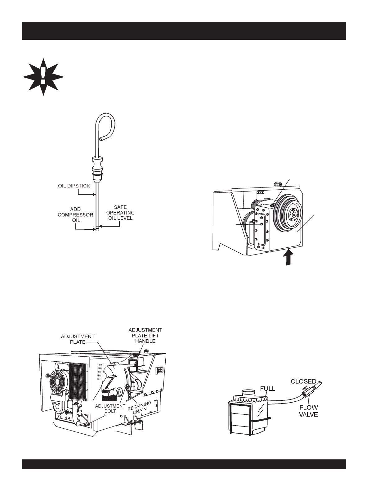
MG-30 PUMP — PRE-INSPECTION (PUMP)
CAUTIONCAUTION
CAUTION
CAUTIONCAUTION
2. Raise the speed reducer adjustment lift handle slightly to
NEVER let the air compressor oil level fall
below the
operation, the oil level should be to the
mark
the dipstick. Fill with recommended type oil
as listed in Table 7.
lower mark.
or at least between the two marks on
For normal
full
3. Next, raise the lift handle all the way upwards until the
4. There are 2 plugs (Figure 32) located on the metal cover of
5. Remove the bottom most plug (
6. If oil does not begin to flow as the plug is being removed,
7. Remove the oil fill plug and add SAE 90 wt. motor oil. DO
remove the V-belt from the 4-grove pulley.
speed reducer unit is sitting in a vertical position. Lock unit
in this position.
the speed reducer unit.
weep hole
oil begins to seep out as the plug is being removed, it can
be assumed that the oil level is correct.
then it can be assumed that the unit requires oil.
NOT over fill.
FILL
PLUG
WEEP
HOLE
) from the unit. If
SPEED
REDUCER
UNIT
Figure 30. Compressor Dipstick (Oil Levels)
SPEED REDUCER OIL CHECK
When checking the oil level of the
to have the speed reducer placed in an upright position (vertical).
Perform the following steps when checking the oil level of the
speed reducer unit:
1. Release the adjustment plate retaining chain (Figure 31)
that secures the speed reducer to the pump frame, then
remove the adjustment bolt from the slider cavity.
speed reducer
unit, it is best
Figure 32. Speed reducer Unit (Vertical Position)
8. Reinstall oil fill plug and make sure weep hole plug has
been tighten securely.
9. Place speed reducer unit into desired operating position,
reinstall V-belt, insert adjustment bolt and secure safety
chain.
PISTON OILER TANK CHECK
1. Fill the piston oiler tank (Figure 33) to the "
normal operating conditions. Check regularly. Fill with SAE
30 wt. type motor oil. The oiler tank capacity is 1.5 quarts
(1.14 liters). Turn flow valve to the
filling oiler tank.
VERTICAL
CLOSED
FULL
" level for
position when
Figure 31. Speed Reducer (Hardware)
PAGE 38 — MAYCO MG-30 PUMP — OPERATION AND PARTS MANUAL — REV. #3 (09/15/11)
Figure 33. Piston Oiler Tank
Page 39
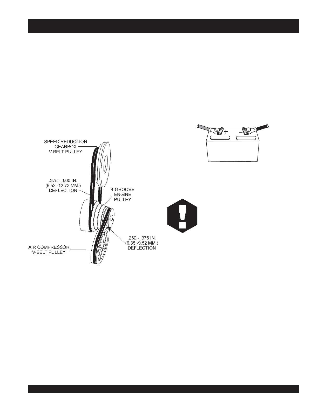
MG-30 PUMP — PRE-INSPECTION (PUMP)
V-BELT CHECK
1. Visually inspect the both the air compressor and speed reduction gearbox V-belts for cracks, fraying, wear or oiliness.
2. Make sure V-belt does not the bottom the pulley groove.
3. Check the
pushing midway through the two pulleys. The V-belt deflection should be between .250 to .375 inches (6.35 to 9.52 mm).
4. Check the
(Figure 34) by pushing midway through the two pulleys. The
V-belt deflection should be between .375 to .500 inches
(9.52 to 12.72 mm).
air compressor
speed reduction gearbox
V-belt tension (Figure 34) by
V-belt tension
BATTERY CHECK
Battery Check
A 12-volt DC battery (Figure 35) is shipped dry, and will require
a proper electrolyte level for operation.
ALWAYS be sure that the battery cables are properly
connected to the battery terminals as shown below. Generally
the
RED
the battery, and the BLACK cable will be connected to the
negative terminal of the battery.
cable will be connected to the positive terminal of
POSITIVE NEGATIVE
RED BLACK
BATTERY
Figure 35. Battery Check
Figure 34. V-Belt Check
WARNING :
If the battery cables are connected
incorrectly, electrical damage will occur
causing damage to the pump's electrical
circuits. Pay close attention to the polarity
of the battery when connecting the battery.
MAYCO MG-30 PUMP — OPERATION AND PARTS MANUAL — REV. #3 (09/15/11) — PAGE 39
Page 40

MG-30 PUMP — INITIAL START-UP (PUMP)
PUSH
This section is intended to assist the operator with the initial
start-up of the MG-30 plaster mortar pump. It is extremely
important that this section be read carefully before attempting to
3.
and pull the round black knob about halfway out. Make
sure that the throttle lock knob has been dis-engaged.
use the pump in the field.
DO NOT use your pump until this section has
been read and is thoroughly understood.
CAUTION:
Failure to understand the operation of the Mayco
plaster mortar pump could result in severe
damage to the pump or personal injury.
the "RED" button (Figure 37) on the throttle control
PUSH-IN, THEN PULL
TO SET THROTTLE
(RPM’s)
THROTTLE LOCK
KNOB, TURN CLOCKWISE
TO LOCK THROTTLE CABLE.
THROTTLE RELEASE
HOSE CONNECTIONS
AND STOP BUTTON
1. Connect pressure relief valve to pump outlet with ball
pointing downward.
2. Connect the material hose.
4. Place the pump control switch (Figure 38) on the control
panel in the center position (no pumping).
2. When using 2-inch hose, it is always attached to the relief
valve.
3. Make sure that all hose connections are watertight. Check
hose for kinks, make sure that it lays flat.
4. Make sure that there are no leaky connections around the
pump head and hose.
5. Connect air compressor hose line and nozzle.
STARTING THE ENGINE
The following steps outline the procedure for starting the
.
engine
1. Inspect piston cups, balls and other parts of the piston head
pump's
5. Insert ignition key into ignition switch (Figure 39) and turn
key clockwise to the START position. Once engine starts,
release key.
before starting engine. Make sure all piston head
components are in good working condition and are not
worn. Replace any worn parts immediately.
2. Open the
piston oiler valve
(Figure 36) slightly. Verify
that oil is flowing through the lines, but not excessively. DO
NOT start pump for at least 5 minutes.
PUSH ALL THE DOWN
TO STOP ENGINE
Figure 37. Throttle Control Knob (Mixer)
Figure 38. Pumping Control Switch
Center Position (No Pumping)
HATZ
DIESEL
START
Figure 39. Engine Status/Ignition Console
Figure 36. Piston Oiler Valve (Open)
6. Except for the "
Happy Face"
status LED, verify that all
other engine status LED's are OFF.
PAGE 40 — MAYCO MG-30 PUMP — OPERATION AND PARTS MANUAL — REV. #3 (09/15/11)
Page 41
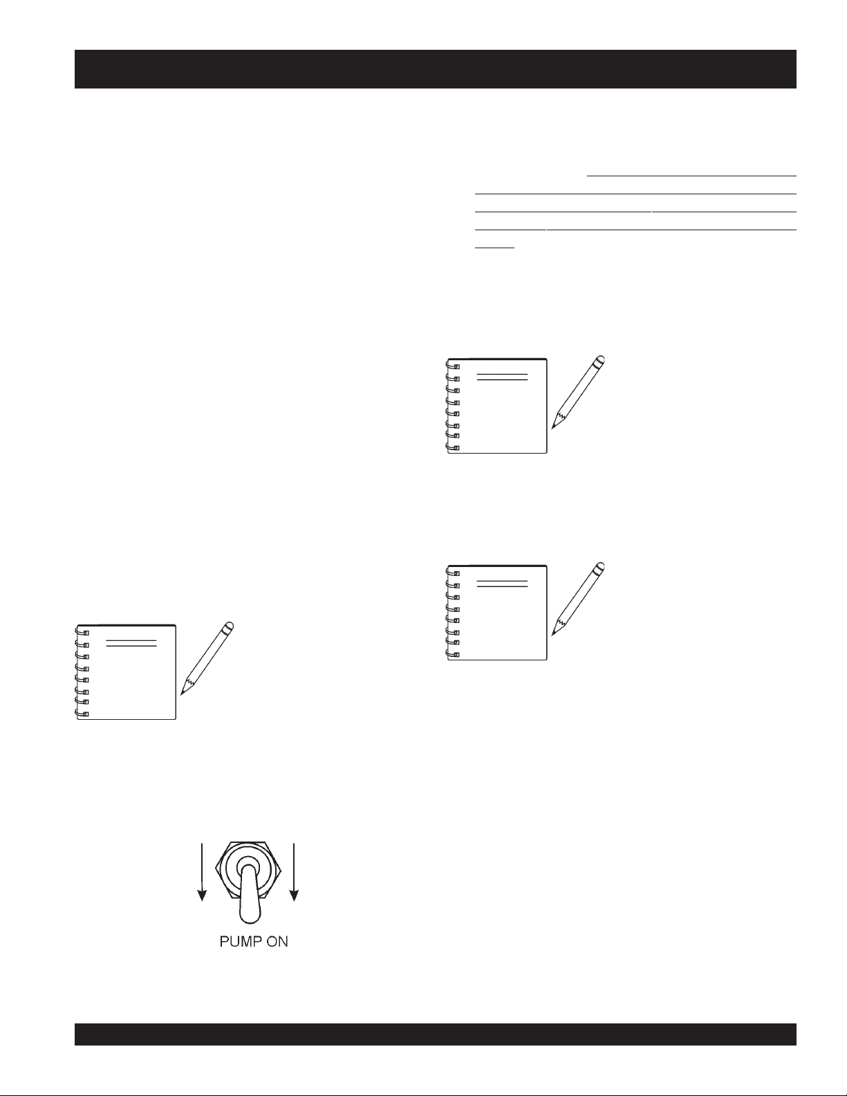
MG-30 PUMP — INITIAL START-UP/OPERATION
Engine Status LED's Definitions.
■
"
Happy Face
the engine and associated components are functioning
correctly.
■
"
Battery
battery charging system is not working correctly. If this LED
remains ON, stop the engine and correct the problem.
■
"
Oil Pressure
the Oil pressure is low. If this LED remains ON, stop the engine
and correct the problem.
■
"
Water Temperature
that the Water temperature is too high. If this LED remains
ON, stop the engine and correct the problem.
■
"
Air Filter
filter is dirty and is not functioning correctly. If this LED remains
ON, stop the engine and correct the problem.
7. Let engine run at idling speed for approximately 5 minutes.
8. Lubricate the pump head and hose by filling the hopper
half full with clean water.
pump head and hose, is that dry surfaces remove water,
which causes the hose to pack.
" status LED. This LED when lit indicates that
" status LED. This LED when lit indicates that the
" status LED. This LED when lit indicates that
" status LED. This LED when lit indicates
" status LED. This LED when lit indicates that the air
The purpose of lubricating the
10. Permit water to be pumped out until it reaches a level just
above hopper inlet throat.
11. Grab dump handle on mixer and dump contents of mixing
drum into hopper.
MATERIAL HAS REACHED END OF HOSE OTHERWISE THIS MAY CAUSE SEPARATION OF
MATERIAL, WHICH COULD CLOG UP PUMP AND
HOSE.
12. If the pump is allowed to suck air at any time, an air block
can develop and the machine will not pump. The air block
can be relieved by opening the pressure release valve
until material flows from the valve.
NOTE
13. Place the pump control switch in the center position to stop
pumping. Install spray nozzle.
14. The plaster and motor pump is now ready to operational.
DO NOT STOP MACHINE UNTIL
Compensator (cam-actuated)
piston will not normally move
when pumping water, as material
back-pressure is required to
return piston to engage cam.
NOTE
If hoses have not been thoroughly
cleaned out, it is suggested that
NOTE
9. Place the pump control switch (Figure 40) on the control
panel in the
down
they be cleaned now to remove
any accumulation of dried sand
etc. which could cause plugging
of hose when material is pumped
Cleaning Procedure
(see
position (pumping).
important that periodic inspections be made during operation.
This preventive maintenance will save hours of un-necessary
maintenance and down time at the job site.
).
It is suggested that the "
Connections
Engine" sections be carefully read.
In addition the hose and fittings
should be checked daily prior to
starting the pump. It is also
" and "
Hose
Starting the
Figure 40. Pumping Control Switch
Down Position (Pumping)
MAYCO MG-30 PUMP — OPERATION AND PARTS MANUAL — REV. #3 (09/15/11) — PAGE 41
Page 42
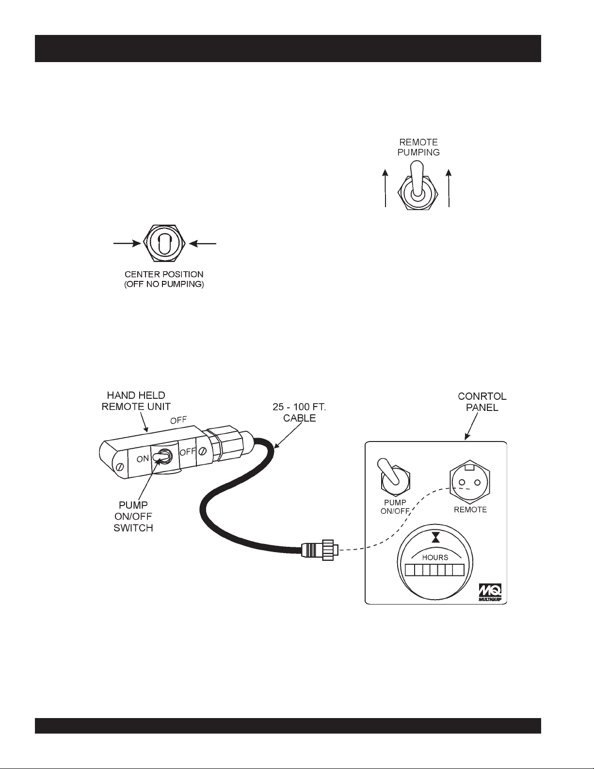
MG-30 PUMP — REMOTE OPERATION
REMOTE PUMP OPERATION
The remote operation of the pump is identical to the manual
operation of the pump, except that the pump can be controlled
25-100
by a
The following steps outline the procedure for operating the pump
remotely.
1. Following the steps as outlined in the "
2. Place the pump control switch (Figure 41) on the control
ft. cable.
Hose Connections
Starting the Engine
and "
panel in the center position (no pumping).
Figure 41. Pumping Switch (No Pumping)
".
3. Plug the remote cable (Figure 42) into the remote
receptacle on the control panel. Tighten securely.
4. Place the pump control switch on the control panel (Figure 42) in
the
"
5. To
6. To
begin
switch (Figure 43) on the hand held remote unit to the ON
position.
stop
(Figure 43) on the hand held remote unit to the OFF
position.
up
position (remote pumping).
Figure 42. Pumping Control Switch
Up Position (Remote Pumping)
pumping remotely, place the pumping control
pumping remotely, place the pumping control switch
Figure 43. Hand Held Remote Cable Configuration
PAGE 42 — MAYCO MG-30 PUMP — OPERATION AND PARTS MANUAL — REV. #3 (09/15/11)
Page 43

MG-30 PUMP — TOWING GUIDELINES
■
Towing Safety Precautions
CAUTION :
■
Check with your county or state safety
towing regulations department before
pump
towing your
To reduce the possibility of an accident while transporting
the pump on public roads, always make sure that the trailer
and the towing vehicle are in good operating condition and
both units are mechanically sound.
The following list of suggestions should be used when towing
the pump :
■
Make sure that the hitch and coupling of the towing
vehicle are rated equal to, or greater than the trailer "gross
vehicle weight rating" (GVWR).
■
ALWAYS inspect the hitch and coupling for wear. NEVER
tow the pump with defective hitches, couplings, chains
etc.
■
CHECK the tire air pressure on both the towing vehicle
and the trailer. Also check the tire tread wear on both
vehicles.
■
ALWAYS make sure the trailer section of the pump is
equipped with a "Safety Chain".
■
ALWAYS attach the pump 's safety chain to the frame
of the towing vehicle.
■
ALWAYS make sure that the vehicle directional, backup,
brake, and trailer lights are connected properly and are
working properly.
■
Remember in most cases the maximum speed unless
otherwise posted for highway towing is 55 MPH, however
before towing your pump , check your local state, and
county vehicle towing requirements. Recommended offroad towing is not to exceed 10 MPH or less depending
on type of terrain.
■
Place
chocked blocks
rolling,
while parked.
underneath wheel to prevent
.
Avoid sudden stops and starts. This can cause skidding, or
jackknifing. Smooth, gradual starts and stops will improve
gas milage.
■
Avoid sharp turns to prevent rolling.
■
DO NOT transport pump with fuel in the fuel tank.
CAUTION :
Mixer Trailer Vehicle Connection
1. Check the vehicle hitch ball, and trailer coupler for signs
of wear or damage. Replace any parts that are worn or
damaged before towing.
2. Use only the 2-inch ball diameter with a towing capability
of 5,000 lbs. (2,268 kg) as indicated on the trailer's
coupler. Use of any other ball diameter will create an
extremely dangerous condition which can result in
separation of the coupler and ball or ball failure.
3. Be sure the coupler is secured to the hitch ball and the
lock lever is down (locked).
4. Attach safety chains as shown in Figures 43 and 44.
Remember to
pump frame.
5. After towing for about 50 miles recheck the entire towing
system for tightness.
Recommended Maintenance
1. Smear ball socket and clamp face with chassis grease.
Periodically oil pivot points and were surfaces of coupler
with SAE 30 W motor oil.
2. When parking or storing the pump , keep the coupler off
the ground so dirt and other debris will not build up in
the ball socket.
If the trailer coupler is deformed, replace
entire coupler. NEVER tow the pump with
a defective trailer coupler. There exist the
possibility of the trailer separating from the
towing vehicle.
cross
the safety chains underneath the
■
Inflate tires to correct pressure, inspect tires for cuts,
and excessive wear. See Table 9 (Tire Wear Troubleshooting).
■
Check wheel mounting lug nuts with a torque wrench.
Torque wheel lug nuts as described in the "
Torque Requirements
■
Check tightness of suspension hardware (nuts and bolts).
MAYCO MG-30 PUMP — OPERATION AND PARTS MANUAL — REV. #3 (09/15/11) — PAGE 43
", Table 10.
Lug Nut
Page 44
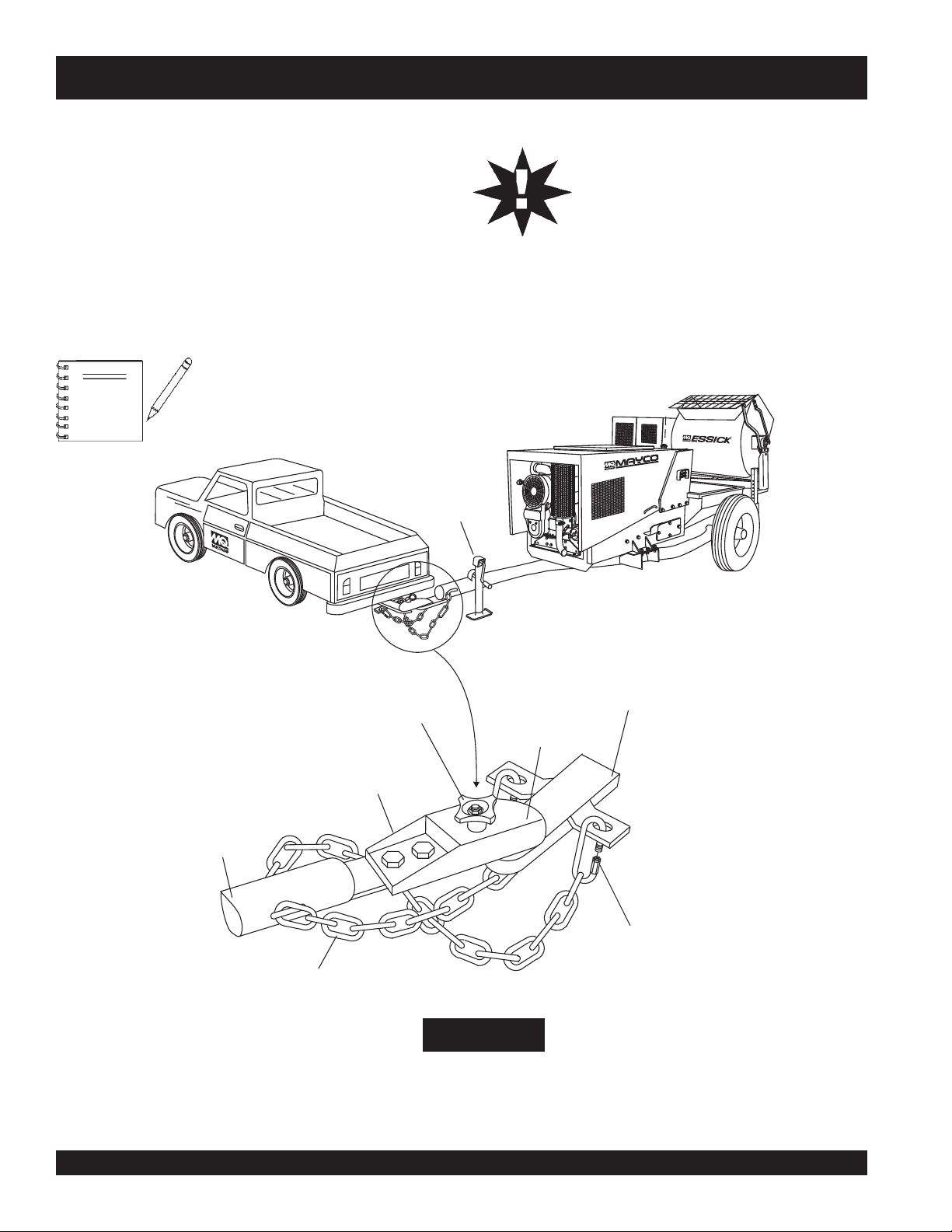
MG-30 PUMP — TOWING GUIDELINES
Towing Instructions (Mobil Unit)
CAUTION:
Before attempting to tow this pump , check the following:
1.
ALWAYS
close the fuel shut-off valve on the pump and
mixer before towing the pump to prevent possible fuel
leakage into the engine crankcase.
2. Securely attach the pump's towing coupler to the towing
vehicle's hitch as shown in Figure 44.
3. Attach both safety chains so that they cross underneath
the pump frame as shown in Figure 44.
4. Make certain the wheel lug nuts and axle mounting
hardware are tight.
5. Check the tire pressure and overall condition of the tires.
6.
ALWAYS
locked in place before towing.
NOTE
Be sure to
underneath pump frame.
always cross
safety chain
HAND WINCH
ADJUST TRAILER
HEIGHT
DO NOT tow the pump unless the mixing drum
and hopper are
make sure the
MG30-M2D
completely empty.
dump handle
and
grill
are
PUMP
FRAME
1-800 MAYCO
2-INCH
TRAILER
COUPLER
SAFETY CHAIN
COUPLER
LOCK KNOB
2-INCH
TRAILER
HITCH
2 INCH BALL
SAFETY CHAIN
MASTER LINK
IMPORTANT!
CROSS BOTH
SAFETY CHAINS
Figure 44. Pump Safety Chain
and Coupler (Mobil Unit)
PAGE 44 — MAYCO MG-30 PUMP — OPERATION AND PARTS MANUAL — REV. #3 (09/15/11)
Page 45
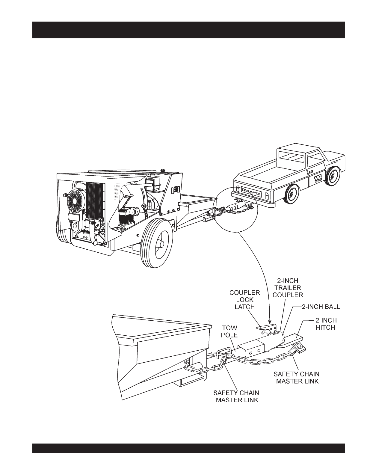
MG-30 PUMP — TOWING GUIDELINES
Towing Instructions (Tag Unit)
Before attempting to tow this pump, check the following:
1.
ALWAYS
engine before towing the pump to prevent possible fuel
leakage into the engine crankcase.
2. Securely attach the tag unit's towing coupler to the towing
vehicle's hitch as shown in Figure 45.
3. Attach the safety chain to the pump frame and towing
vehicle as shown in Figure 45.
close the fuel shut-off valve on the pump's
Figure 45. Pump Safety Chain
and Coupler (Tag Unit)
MAYCO MG-30 PUMP — OPERATION AND PARTS MANUAL — REV. #3 (09/15/11) — PAGE 45
Page 46
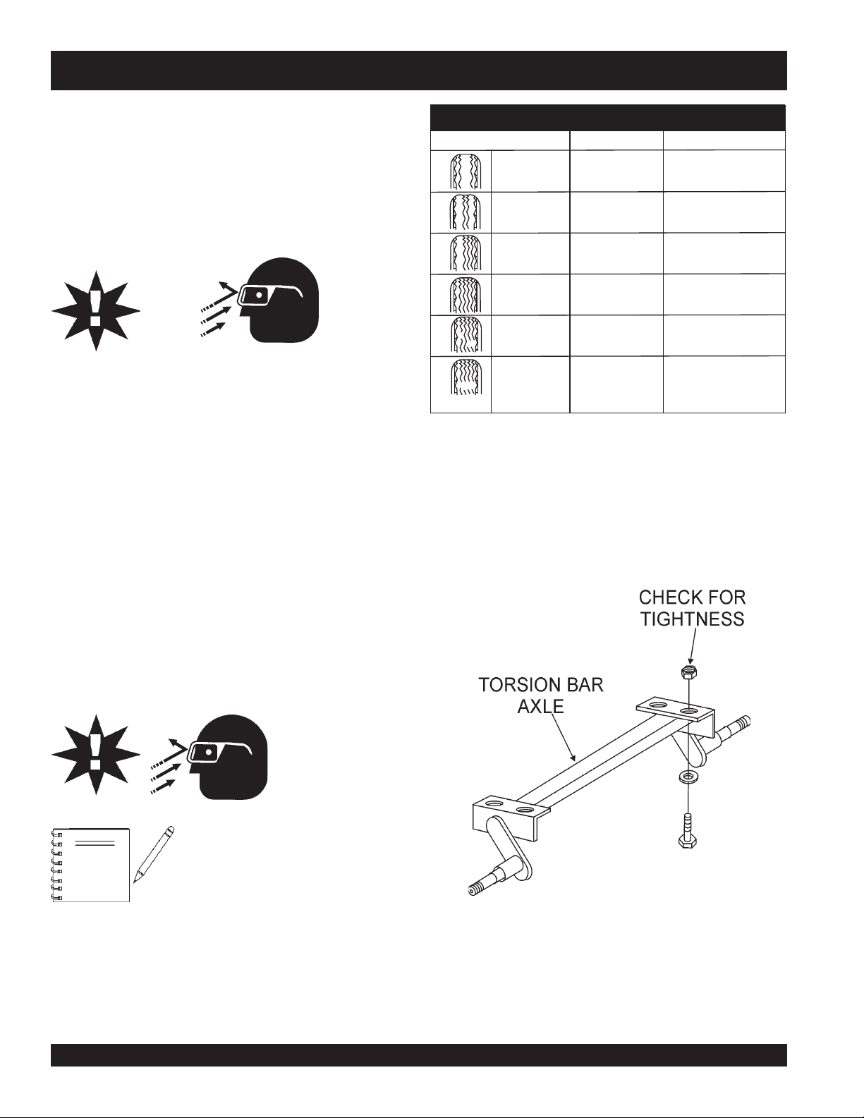
MG-30 PUMP — TRAILER SAFETY GUIDELINES
Tires/Wheels/Lug Nuts
Tires and wheels are a very important and critical compo-
WEAR PATTERN SOLUTION
nents of the trailer. When specifying or replacing the trailer
wheels it is important the wheels, tires, and axle are properly matched.
CAUTION :
DO NOT attempt to repair or modify a wheel. DO NOT install
an inter-tube to correct a leak through the rim. If the rim is
cracked, the air pressure in the inter-tube may cause pieces
of the rim to explode (break-off) with great force and can
cause serious eye or bodily injury.
Suspension (Tag Unit)
Tires Wear/Inflation
Tire inflation pressure is the most important factor in tire
life. Pressure should be checked cold before operation. DO
NOT bleed air from tires when they are
hot!
. Check inflation
pressure weekly during use to insure the maximum tire life
and tread wear.
The torsion bar suspension (
hardware (Figure 45) should be visually inspected every 6,000
miles for signs of excessive wear, elongation of bolt holes,
and loosening of fasteners. Replace all damaged parts immediately.
TABLE 9. TIRE WEAR TROUBLESHOOTING
CAUSE
Adjust pressure to
Center Wear
Edge Wear Under Inflation
Side Wear
Toe Wear
Cupping
Flat Spots
Over Inflation
Loss of chamber
or overloading.
Incorrect toe-in
Out-of balance
Wheel lockup &
tire skidding.
Tag unit only
particular load per
tire manufacturer.
Adjust pressure to
particular load per
tire manufacturer.
Make sure load does
not exceed axle rating.
Align wheels.
Align wheels.
Check bearing adjustment and balance tires.
Avoid sudden stops
when possible and
adjust brakes.
) and associated
Table 9 (Tire Wear Troubleshooting) will help pinpoint the
causes and solutions of tire wear problems.
CAUTION :
NOTE
ALWAYS
removing or installing force fitted
parts. Failure to comply may result
in serious injury.
wear
safety glasses
when
Figure 46. Tag Unit Suspension Components
PAGE 46 — MAYCO MG-30 PUMP — OPERATION AND PARTS MANUAL — REV. #3 (09/15/11)
Page 47

MG-30 PUMP — TRAILER SAFETY GUIDELINES
Lug Nut Torque Requirements
It is extremely important to apply and maintain proper wheel
mounting torque on the trailer. Be sure to use only the fasteners matched to the cone angle of the wheel. Proper procedure for attachment of the wheels is as follows:
1. Start all wheel lug nuts by hand.
2. Torque all lug nuts in sequence. See Figure 47. DO NOT
torque the wheel lug nuts all the way down. Tighten each lug
nut in 3 separate passes as defined by Table 10.
stnemeriuqeReuqroTeriT.01elbaT
eziSleehWssaPtsriF
SBL-TF
"2152-0204-5356-05
"3152-0204-5356-05
"4152-0206-05021-09
5152-0206-05021-09
"
"6152-0206-05021-09
ssaPdnoceS
SBL-TF
ssaPdrihT
SBL-TF
3. After first road use, retorque all lug nuts in sequence. Check
all wheel lug nuts periodically.
NOTE
NEVER!
to tighten wheel lug nuts.
use an pneumatic air gun
Figure 47. Wheel Lug Nuts Tightening Sequence
MAYCO MG-30 PUMP — OPERATION AND PARTS MANUAL — REV. #3 (09/15/11) — PAGE 47
Page 48

SHAFT SEALS
CAUTION:
MG-30 PUMP — MAINTENANCE (MIXER)
trahCeuqroT.11elbaT
IMPORTANT -DRUM HEAD SEAL CARE
Grease seals every
40 hours
of operation
using any grade #1 lithium base grease. Apply
grease until visible inside of mixing tub (over
grease). This will purge seal system of
contamination.
GEAR/CLUTCH REDUCTION ASSEMBLY LUBRICATION
The gear/clutch reduction assembly has two separate
compartments. Each of which must be filled with its proper
lubricant and checked at regular intervals.
clutch compartment
The
should be filled with a good grade of
number 30 SAE engine oil which can be poured through the
filler hole located just above the clutch inspection door on the
opposite side of the transmission. Fill the clutch compartment
with 30 SAE engine oil until it overflows the oil level plug located
on the shifter side of the clutch compartment . Check this oil level
every two or three months and add oil as required. Drain and
refill once a year.
reduction gear, upper compartment
The
should be filled with
number 90 SAE oil, as used in automobile transmissions. The
filler plug is at the top of the reduction gear case and the oil level
plug is on the same side of the case as the clutch lever. Fill the
reduction gear compartment with 90 SAE transmission oil until it
ENGINE OIL
1. If mixer's engine oil is low, fill engine crankcase with
lubricating oil through filler hole, but DO NOT overfill.
2. The oil listed in Table 7 is recommended to ensure better
engine performance. Use class CD or higher grade motor
oil.
AIR CLEANER (DRY TYPE)
1. Change the air cleaner every 500 hours. See Figure 12
for location of air cleaner.
FUEL FILTER/FUEL TANK
1. Change the fuel filter every 500 hours.
2. Siphon water out of fuel tank once a year.
overflows the oil level plug. Check this oil level every two or
three months and add oil as required. Drain and refill once a
CLEANING
year.
ALWAYS make sure engine is OFF before cleaning the inside
PADDLE SHAFT BEARINGS
The paddle shaft in the MQ ESSICK EM120SM mixer rotates in
sealed ball bearings, which require no additional lubrication as
of the drum. NEVER put hands, fingers or arms inside mixing
drum when engine is ON.
NEVER pour or spray water over engine.
they are packed and sealed at the factory.
For consistent performance, long life and high quality mixing,
There is, on each end of the mixing drum, a zerk grease fitting
(pivot point). Grease these fittings once a week as they lubricate
Failure
the dumping mechanism of the mixing drum.
to lubricate
the zerk grease fittings once a week will cause the dumping
thoroughly clean the mixer inside and out at the end of each
day’s operation. To prevent lumps of dried mortar from forming
and contamination of future batches, DO NOT allow a buildup of
materials to form on the blades or anywhere inside the drum.
mechanism to stiffen, making the mixer hard to dump.
retemaiDerawdraHeuqroT
2
)mm49.7(81-"61-5m/fgk711(.sbl/tf42
)mm35.9(42-"8/3m/fgk081(.sbl/tf73
)mm07.21(31-"2/1m/fgk091(.sbl/tf93
)mm07.21(31-"2/1
8edarG
)
2
)
2
)
2
)
m/fgk934(.sbl/tf09
HARDWARE
Check all hardware on the mixer before starting. Periodically
inspect all hardware. Loose hardware can contribute to early
component failure and poor performance. Use Table 11 (Torque
Chart) as a general guideline and keep all hardware tight.
PAGE 48 — MAYCO MG-30 PUMP — OPERATION AND PARTS MANUAL — REV. #3 (09/15/11)
Page 49
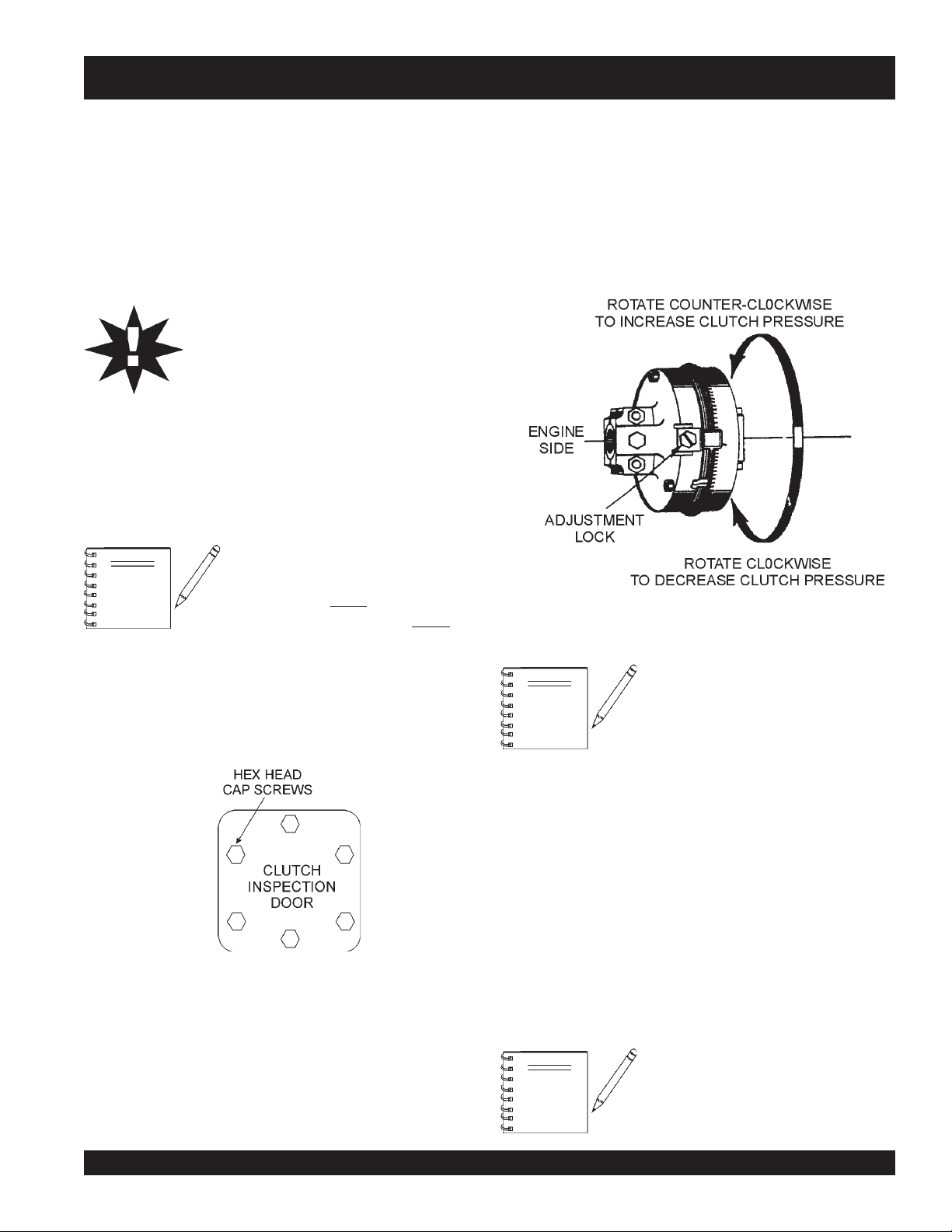
MG-30 PUMP — MAINTENANCE (MIXER)
Clutch Adjustment Mechanical 12 CF Mixer
If the rotating mixing paddles appear to be losing rotational speed,
it may be necessary to adjust the clutch. For optimum
performance Multiquip recommends 35-55 lbs. applied pressure
to the hand clutch lever. After the first initial operating hours (8)
check the clutch for proper engagement pressure.
Clutch Adjustment Procedure
CAUTION:
A. Rotate the clutch using the recoil starter until the
adjustment lock
Using a flat blade screwdriver loosen the adjustment bolt
just enough to release the adjustment lock.
B. Using a punch, rotate the
one notch at a time in the counter-clockwise direction until
a firm 35 to 55 lbs. pressure is felt when engaging the
clutch lever (the lever should snap into the engaged
position).
ALWAYS stop the engine before attempting
this procedure.
1. To gain access to the " Gear Reduction Compartment"
remove the four 9/16-inch hex head bolts that secure the
hood to the engine and remove engine hood.
2. Drain the clutch compartment oil (Figure 19) by removing
the magnetic 3/8 plug located at the bottom of the Gear
Reduction Assembly.
The Gear Reduction Compartment
NOTE
compartment contains the actual gear reduction. Remember
each compartment requires a different type of lubricating oil.
consist of two compartments, a lower
lower
and upper. The
houses the clutch, the
compartment
uppe
r
Figure 49. Clutch Adjustment Lock Location
(Figure 49) P/N EM934040 is visible.
adjusting ring
P/N EM 934045
3. To gain access to the "
the six 1/2-inch cap screws (Figure 48 )and lock washers
that secure the clutch inspection door. Remove door and
gasket.
Figure 48. Clutch Inspection Door
4. Check that the clutch is disengaged by pulling the shifter
lever towards the engine end of the mixer.
5. Refer to Figure 48 for steps 5A through 5F:
clutch Inspection door
" remove
NOTE
C. When the clutch has been satisfactorily adjusted reinstall
the
D. Reinstall the
inch cap screws and lock washers, and also check that the
gasket is not worn or broken.
E. When the clutch has been satisfactorily adjusted reinstall
the
F. Remove the 3/8-inch square head pipe plug located on
the lower clutch compartment. Refill the clutch
compartment with 2-1/4 quarts of SAE 30 motor oil to the
level of the plug. When done reinstall plug.
G. Start engine, check for proper clutch engagement and
inspect for any oil leaks.
NOTE
If the clutch cannot be adjusted, it may
be necessary to inspect or replace the
clutch.
adjustment lock
clutch Inspection door
adjustment lock
P/N EM 934040 and tighten lock bolt.
P/N EM 934040 and tighten lock bolt.
Any questions regarding the above
procedure please contact the
Multiquip Service Department.
using the six 1/2-
MAYCO MG-30 PUMP — OPERATION AND PARTS MANUAL — REV. #3 (09/15/11) — PAGE 49
Page 50

MG-30 PUMP — MAINTENANCE (PUMP)
CLEANING THE PUMP
When changing from one material to another, or when shutting
down the machine for a period of time, or at the end of the working
day, the machine should be washed out and the hoses cleaned
to prevent the material from setting and causing difficulties when
operation is resumed. FOLLOWING IS A SUGGESTED
PROCEDURE FOR CLEANING THE MACHINE AND HOSES:
1. Dump all material from the
mixer
into the hopper and
pump material form hopper. Scrape down the sides of
the hopper to clean off as much material as possible.
Shut off pump; open pressure release valve to relieve
hose pressure and disconnect material hose from
machine.
2. Add
15 to 20 gallons
of water to the hopper. Start the
pump and flush water through the pump to remove all
material and sand from the pump. Shut off pump; insert
a wet sponge into the open end of the material hose and
connect the hose to the pump.
3. Add
15 to 20 gallons
of water to the hopper. Remove
the nozzle from the end of the hose, start the pump,
and force the sponge through the hose. The sponge
scrubs down the inside of the hose and acts as a divider
between the water and the material. It prevents the
water from channeling through the hose, removing the
cement or gypsum while leaving a portion of the sand
still in the hose. Sand or any other material left in the
hose will cause the hose to pack up when next used.
4. Repeat Steps 2 and 3 until no additional material is
flushed from the hose. Avoid dumping the dirty water
produced by cleaning the mixer into the pump hopper.
The sand can settle out and clog the pump.
5. Wash and wire-brush nozzle and oil it. Clean screen
and hose down machine with water.
6. Spray entire machine with regular motor oil. This will
assist you in keeping it clean
ENGINE (Hatz Model 2M41LZ Diesel)
The Model MG30-2 is equipped with a Model 2M41LZ, 35 H.P.
air-cooled diesel engine. For information concerning the
procedure in checking, removing, cleaning, etc. of the various
engine parts or any other information on the engine not contained
herein, refer to the engine manufacturer’s instruction manual.
CRANKCASE
1. The crankcase oil should be
HOURS of operation.
2. The old oil should be
after
plug located on engine base. Drain engine crankcase
oil when oil is warm it will flow more freely.
AIR CLEANER
1. The air cleaner, mounted on the side of the engine, is
an essential engine component. It filters the air entering
the carburetor. Depending on the conditions under which
the engine is operated, servicing of the air cleaner will
vary from a
conditions to
FUEL STRAINER
1. The fuel strainer is very necessary in preventing
sediment, dirt and water from entering the carburetor.
This strainer is equipped with a glass bowl and should
be inspected at least
water is present.
AIR COMPRESSOR
1. A
weekly
crankcase oil level to make sure it is at the
at least between the two marks on the dipstick (Figure 29).
NEVER
to Table 7) for proper oil recommendation.) Crankcase
oil capacity is 1.5 pints ( .709 liters)
2. The oil should be completely changed approximately.
ever y 30
The crankcase should be thoroughly cleaned with each
oil change. Refer to the Quincy Compressor
Maintenance Manual for further information concerning
lubrication, adjustment and maintenance of the air
compressor.
CHECKED EVERY 8
DRAINED
EVERY 40 HOURS
few days
of operation in comparatively clean
twice a day
once a week
and
FRESH OIL ADDED
of operation. To drain oil, remove
in dusty conditions.
and cleaned if dirt or
check should be made of the compressor's
full
mark, or
allow the oil to fall below the
days; sooner
if oil becomes dirty or diluted.
lower
mark. (Refer
3. An air filter has been installed on the air compressor.
This filter should be checked and cleaned
WEEKLY
normal conditions. If extremely dusty conditions prevail,
it is advisable to clean the air filter at least once a day.
4. To clean air filter, soak sponge element in solvent and
let it dry out; then dip element in clean oil, permit oil to
drip off and reinstall on unit.
PAGE 50 — MAYCO MG-30 PUMP — OPERATION AND PARTS MANUAL — REV. #3 (09/15/11)
under
Page 51
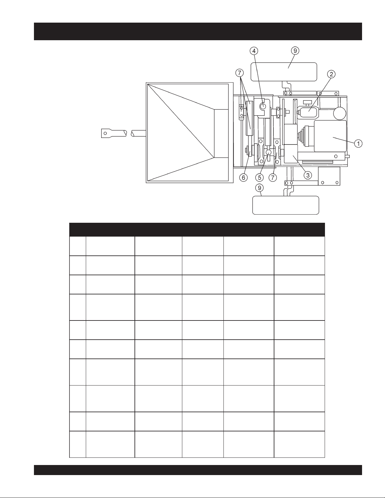
MG-30 PUMP — MAINTENANCE (PUMP)
Figure 50 show the pump maintenance points, see Table 12
below for maintenance intervals.
Figure 50. Pump Maintenance Points
slavretnIecnanetniaMpmuP.21elbaT
.FERnoitpircseDtnacirbuL
lavretnIegnahC
1esacknarCenignEsruoH04yrevE.stq
2rosserpmoCsyaD03yrevEstnip5.1
3rec
4reli
5reliOmaCyaDyrevEkcehCtleFkaoS03EASsawercStleftsujdA
6doRgnitcennoCyliaDkcehCtohS-1esoprup-itlum2.oN
7rekcor,dorhsuP
udeRdeepSshtnoM0.6yrevEtcerrocotlliF
OnotsiPyaDaeciwTknaTlliF03EASevlavwolfesolC
yliaDkcehCtohS-1esoprup-itlum2.oN
dnatfahs,mra
.sgniraeb
fOtnuomA
tnacirbuL
2.3-8.5
)retil0.3-5.5(
)sretil907.(
liOgnitarepo
leveL
ro
tnacirbuLepyTskrameR
8elbaTeeS.yliaDkcehC
7elbaTeeS.yliaDkcehC
09EAShtiwylkeewkcehC
esaergevitomotua
.tnelaviuqero
esaergevitomotua
.tnelaviuqe
lacitrevanirecuder
.noitisop
.gnillifnehw
.de
riuqer
tridtneverpothsulF
orrocdna
.nois
tridtneverpothsulF
.noisorrocdna
8sleehWshtnom0.6yrevEderiuqersAgniraebleehW
9)llA
(sgniR-"O"noitallatsnierofeB.deriuqersAesoprup-itlum2.oN
.esaerg
esaergevitomotua
.tnelaviuqero
sakcap-eR
.deriuqer
otgniR-OtaoC
.gnihcn
iptneverp
MAYCO MG-30 PUMP — OPERATION AND PARTS MANUAL — REV. #3 (09/15/11) — PAGE 51
Page 52
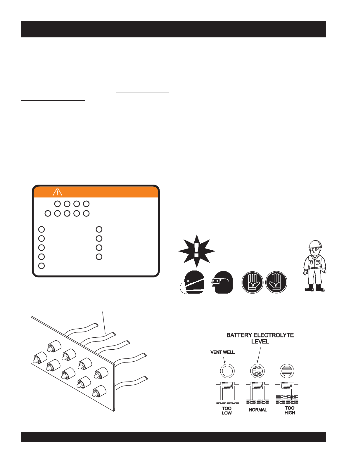
MG-30 PUMP — MAINTENANCE (PUMP)
SPEED REDUCER UNIT
The speed reducer unit is of a constant-mesh type and totally
enclosed, with all gears running in oil.
CHECK THE OIL LEVEL
EVERY WEEK.
The speed reducer should be completely drained every 6 months.
Refill with a good grade of S.A.E. 30 Oil.
CAUTION: KEEP OIL
AT THE PROPER LEVEL. Too much oil will cause overheating
and too little oil will cause gear failure. When the adding of oil to
the speed reducer is required. Reference the "
Oil Check
" section on page 38.
Speed Reducer
LUBRICATION PANEL
Located on the side of the pump is a lubrication panel (Figure 51).
Grease
all ports daily
with two to three shots of #2 multi-purpose
automotive grease. Over-greasing any bearing will not damage
the machine.
BATTERY MAINTENANCE
Mishandling of the battery shortens the service life of the battery
and adds to maintenance cost. When handling the battery do
the following:
Be careful not to let the battery electrolyte come in
contact with your body or clothing.
Always wear
the battery contains sulfuric acid which burns skin and
eats through clothing.
Always check the battery terminals periodically to
ensure that they are in good condition.
Use wire brush or sand paper to clean the battery
terminals.
Always check battery for cracks or any other
damage. If white pattern appears inside the battery
or paste has accumulated at the bottom, replace
the battery.
MAINTENANCE
1 2 3 4
5 6 7 8 9
1
Cam Rocker Arm Bushings
2
Gear Box Block (Back)
3
Cam Rocker Arm Roller
4
Connecting Rod. (Up)
5
Cam Rocker Arm
(Bearing Housing)
GREASE DAILY,
EVERY ZERK
Use: No. 2 Multipurpose
Automotive Grease
6
Gear Box Block (Front)
7
Connectings Rod. (Down)
8
Crank Rocker Arm (Bushings)
9
Crank Rocker Arm
(Bearing Housing)
513164
If the pump will not be in operation for a long period
of time, store in cool dry place and check the
battery charge level every month to maintain the
performance of the battery.
CAUTION :
eye protection
Wear
safety glasses
, protective clothes, and
mask
and
rubber gloves
or
face
rubber gloves when working
with battery.
, since
LUBRICATION
LINES
Check the battery regularly and make sure that each
electrolyte level is to the bottom of the vent well
(Figure 52). If necessary add only distilled water in a
well-ventilated area.
1
5
6
2
3
7
8
4
9
Figure 51. Lubrication Panel
Figure 52. Battery Electrolyte Levels
PAGE 52 — MAYCO MG-30 PUMP — OPERATION AND PARTS MANUAL — REV. #3 (09/15/11)
Page 53
MG-30 PUMP — MAINTENANCE (PUMP)
RUBBER CHECK BALL
The brass cap and rubber ball should be removed and all parts
cleaned daily
pressure rating of the brass cap, causing the rubber ball to
at an incorrect pressure.
NOTE
Inspect the rubber relief ball
back into the valve. The
age hardening
If the ball is cracked, has flat spots due to wear, pieces broken off
of it or out of round,
To check the rubber ball for age hardening, conduct the
"
bounce
1. Hold the rubber ball in hand 5 feet above a concrete floor.
2. Drop the ball (DO NOT throw the ball downward), simply
release the ball from your hand.
3. First bounce must be 18-inches minimum.
NOTE
NOTE
. Setup of materials will have an affect on the
Failure to properly maintain this
pressure relief valve will create a
dangerous situation of over
pressurizing the pump and delivery.
every day
before reassembling it
ball is subject to wear and possible
.
replace
" inspection test.
the rubber ball
Replace the rubber ball
if it does not pass
the bounce test. DO NOT use a rubber
ball that is defective or worn. When
ordering replacement rubber ball use
Mayco P/N EM400581
When replacing either the
steel
check ball, remember that there
is another check ball that should be
inspected for wear or damage.
check
both
gasket parts are clean when they are
reassembled.
immediately
immediately
visual inspection
check balls. Make sure all
eject
.
rubber
Always
LEATHER PISTON CUPS
The leather piston cups out wear the rubber balls. The leather
cups as well as the rubber balls can have premature wear if
exposed to excessive pumping pressures or jamming of the
pump.
The leather cups are a natural wear component and will require
periodic replacement. The life of the leather cups depends on
many factors, proper lubrication, oil cleanliness, abrasivness of
sand and material.
When the leather cup on the pump side is damaged, it may suck
air on the suction stroke instead of a full charge of material from
the hopper. When this condition occurs, material flow will
decrease.
NOTE
bottom of the lubrication box. Any questions regarding the
lubrication clean-out procedure, contact the MAYCO
Department.
As the leather cups wear, fine cement particles will accumulate
in the bottom of the librication box. Once the cement past reaches
1-inch in height, it is recommended that the lubrication box be
drained (flushed) and cleaned
CHANGING THE LEATHER PISTON CUPS
or
1. Run the piston to the end of its stroke.
2 Remove pump unit.
3. Loosen piston rod nut.
4. Rock piston assembly by hand turning drive belt.
5. Pull cylinder out exposing piston assembly.
6. Remove piston nut.
or
7. Slide piston assembly off piston rod.
8. Check all washers for damage.
9. Replace any component that shows is worn or is
damaged.
10. Check neoprene leather cup expander.
11. Check leather cup and saturate with oil before replacing.
12. Check both felt cam oiler pads for oil saturation, If dry
Rubber Check Plug
saturate each pad with SAE 30 motor oil.
13. Reinstall piston parts in the reverse order that they were
The rubber safety plug should be removed and
Replace this plug if it is defective or worn. See manifold assembly
in this manual when ordering replacement rubber plug.
cleaned daily
.
dis-assembled. Make sure that the piston oiler hose is
at the top of the piston and remains there while the piston
rod nut is being tighten.
14. Remember lubrication of the piston depends on gravity
flow from the oil reservoir to the cam oiler pads.
To ensure
the reservoir
proper level. In addition the lubrication
box must be cleaned periodically. There
are two clean-out ports located at the
maximum cup
must be
life, the oil in
maintained at the
Service
MAYCO MG-30 PUMP — OPERATION AND PARTS MANUAL — REV. #3 (09/15/11) — PAGE 53
Page 54
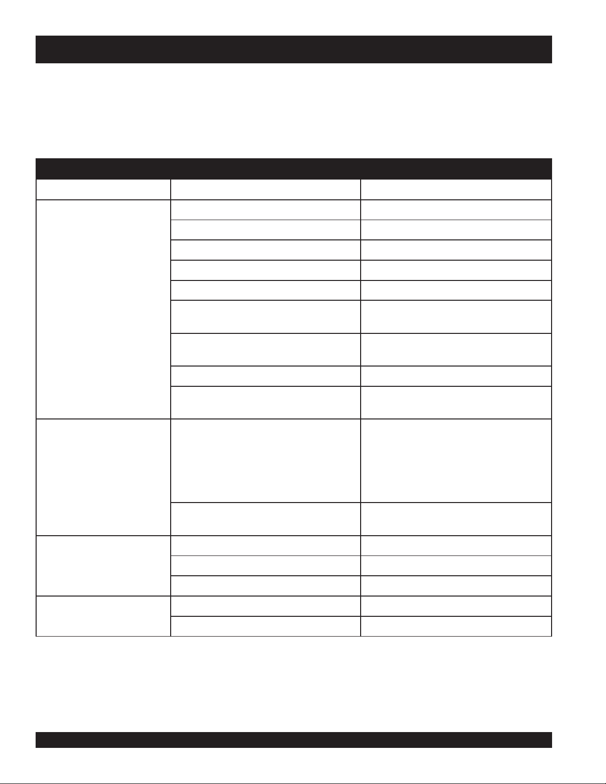
MG-30 PUMP — TROUBLESHOOTING (ENGINE)
Practically all breakdowns can be prevented by proper
handling and maintenance inspections, but in the event of a
breakdown, please take a remedial action following the
diagnosis based on the Engine Troubleshooting (Table 13)
information shown below and on the proceeding page. If the
problem cannot be remedied, please leave the unit just as it
is and consult our company's business office or service
plant.
MOTPMYSMELBORPELBISSOPNOITULOS
oitcejnignihcaerleufoN .metsysleuferitnekcehC.leufddA
?pmupleufevitcefeD.pmupleufecalpeR
?deggolcretlifleuF .knatnaelcdnaretlifleufecalpeR
sitratsrotratstonlliwenignE
,deyaled
.revodenruteb
nacenignehguohtla
?enilylppusleufytluaF .enilleufriaperroecalpeR
?wolootnoisserpmoC
?pmupn
?yltcerrocgnikrowtonrotcejnileuF
?noitisop"POTS"nisirevellortnocdeepS .noitisop"TRATS"otrevellortnocdeepsteS
GNITOOHSELBUORTENIGNE.31ELBAT
rotsuj
dA.sevlavdnarednilyc,notsipkcehC
.launamriaperenignerepriaper
roccanirotcejniecalperroriapeR
.launamriaperenigne
htiwecnad
?wolooterusserpliO .erusserplioenignekcehC
ilerutarepmetgnitratswoL
twoltA
.tratston
.ffodehctiwssiretrats
.noitarepolamron
lliwenigneserutarepme
elelttorhT .noitisopNURotrevelelttorhtnoitisopeR
sanoosspotstubserifenignE
gnirudflestiybspotsenignE
euF.retlifleufecalpeR
?serutarepmetwol
?kcihtootlioenignE
?noitisopPOTSnirev
?dekcolbretlifleuF.retlifleufecalpeR
?dekcolbylppusleuF .metsysleuferitneehtkcehC
?ytpmeknatleuF.leufddA
?dekcolbretlifl
dedeecxetim
hwkcehC
otecnatsiseretauqedanisahsetarapesleuF
.leuf
.ytisocsivlioreporp
roenigneehtpu
narcenignellifeR
.tnemnorivneretniwrof
dnasnoitcurtsnignitratsdlochtiwylpmoC
segremeleuf)dibrutton(raelcrehte
noitcejnimorfhcated(enilleufehtmorf
mraw,detarapesrodibrutsileufehtfI.)pmup
leufetelpmocehtniard
leseidedargretniwhtiwleufeR.metsysylppus
liofoepyttcerrochtiwesack
PAGE 54 — MAYCO MG-30 PUMP — OPERATION AND PARTS MANUAL — REV. #3 (09/15/11)
Page 55

MG-30 PUMP — TROUBLESHOOTING (ENGINE/MIXER)
)DEUNITNOC(GNITOOHSELBUORTENIGNE.31ELBAT
MOTPMYSMELBORPELBISSOPNOITULOS
?ytpmeknatleuF.retlifleufecalpeR
?deggolcretlifleuF.retlifleufecalpeR
dnatuptuo,rewopenignewoL
.deeps
?noitisop
?llufootlevellioenignE ?levellioenignetcerroC
?
dnatuptuorewopenignewoL
tsuahxekcalb,deepswol
.ekoms
dekcolbretlifriA .retlifriaecalperronaelC
?rotcejnitanoitcnuflaM.launamenigneeeS
?etauqedanisignitnevknatleuF .detnevyletauqedasiknattahterusnE
?secnaraelcevlavtcerrocnI .noitacificepsenignerepsevlavtsujdA
Practically all mixer breakdowns can be prevented by proper
handling and maintenance inspections, but in the event of a
breakdown, please take a remedial action following the
diagnosis based on the Mixer Troubleshooting (Table 14)
information shown below and on the proceeding page. If the
problem cannot be remedied, please leave the unit just as it
is and consult our company's business office or service
plant.
detcelesniniamertonseodrevellortnocdeepS
gneeeS
.noitcaevitcerrocroflaunameni
GNITOOHSELBUORTREXIM.41ELBAT
MOTPMYS MELBORPELBISSOP NOITULOS
?niprotcennocnekorB
.etatortonlliwsedalB
?hctulcdetsujda-simroevitcefeD .hctulcecalperrotsujdA
.sdne
murdmorfgnikaellairetaM
)tlit(egrahcsidottluciffidmurD
?slaes
?stekcarb
tfahselddapevitcefedronroW
troppusmurdnrowroevitcefeD
.thgitootdetsujdasedalB .murdfosllawedishcuottsomlayehtlitnusedalbtsujdA
.slaesecalperrotsujdA
.ecalperrotekcarbotesaergylppA
.gniredronehw751369N/PesU.niprotcennocecalpeR
MAYCO MG-30 PUMP — OPERATION AND PARTS MANUAL — REV. #3 (09/15/11) — PAGE 55
Page 56

MG-30 PUMP — TROUBLESHOOTING (PUMP)
GNITOOHSELBUORTPMUP.51ELBAT
MOTPMYS MELBORPELBISSOP NOITULOS
?taesevlavdnasllabevitcefeD
.nwod
swolspmupfonoitcudorpemuloV
llabevlavfeilererusserpytefaS
!tuoswolb
degrahcsidgniebsilairetamoN
.dlofinamteltuoretnecmorf
.sekomsrospilshctulclagufirtneC
?kaelriA .pucrehtaeldna.sgnir-OtcepsnI
?.pmupotffitsootlairetaM .)ycnetsisnoc(ximlairetamkcehC
?enilesohnigolC
?tlebevirdnekorB .tlebevirdecalpeR
?emirpstitsolpmupsaH .ytpmefireppohllif,lairetamrofreppohtcepsnI
?taes
?golclairetaM .noitcurtsboraelc,noitcurtsborofdlofinamtcepsnI
?kaelriA .sgnir-OecalperrotcepsnI
?yltcerrocnitesMPRenignE .gnittestcerrocotMPRenignetsujdA
?)golc(kcaplairetaM .noitcurtsboraelc,metsysyreviledninoitcurtsbotcepsnI
?gninilhctulcnroW .yrassecenfiecalper,raewrofgniniltcepsnI
.yrassecenfiecalper,raew
evlavrosllableetsrorehtaelevitcefeD
.ecalperrotcepsnI
.yrassecenfitaesevlavrosllabecalper,taesevlav
tcepsnioslA.egamadroraewrofsllableetsrorehtaeltcepsnI
eritnekcehC.golcevomeR.golcrofenilesohlairetamtcepsnI
fosngisrofllabkcehcrebburtcepsnidnakcehC.metsysyreviled
?tleb-VnrowroevitcefeD .tleb-VrosserpmocriaecalperrotcepsnI
)rosserpmocria(erusserpriaoN
ecifiroro
?tleb-VnrowroevitcefeD tleb-VrosserpmocriaecalperrotcepsnI
)rosserpmocria(erusserpriawoL
tsniagaskconkmrarotasnepmoC
.skcitsromac
roswolfrevoxoBnoitacirbuL
.lioevissecxesehsalps
?retlifriaytriD .retlifriaecalperronaelC
ecifiroro
?erusserpkcabwoL .htgneldnaezistcerrocrofesohyreviledtcepsnI
?llufxobnoitacirbuL
senilyreviledriani)golc(kcaplairetaM
senilyreviledriani)golc(kcaplairetaM
?detacirbulspucrehtaelnotsiperA .noitacirbulreporprofspucrehtaeltcepsnI
.noitcurtsbo
raelc,noitcurtsbolairetamrofelzzondnaenilyreviledtcepsnI
raelc,noitcurtsbolairetamrofelzzondnaenilyreviledtcepsnI
.noitcurtsbo
.yrassecenfiniard,levellioreporprofxobnoitacirbultcepsnI
.raewrofspucrehtaeltcepsnI
PAGE 56 — MAYCO MG-30 PUMP — OPERATION AND PARTS MANUAL — REV. #3 (09/15/11)
Page 57

MG-30 PUMP — WIRING DIAGRAM
Figure 52. Control Panel/Remote Cable
Wiring Diagram
MAYCO MG-30 PUMP — OPERATION AND PARTS MANUAL — REV. #3 (09/15/11) — PAGE 57
Page 58

MG-30 PUMP — WIRING DIAGRAM
Figure 53. Electrical System Diagram
PAGE 58 — MAYCO MG-30 PUMP — OPERATION AND PARTS MANUAL — REV. #3 (09/15/11)
Page 59
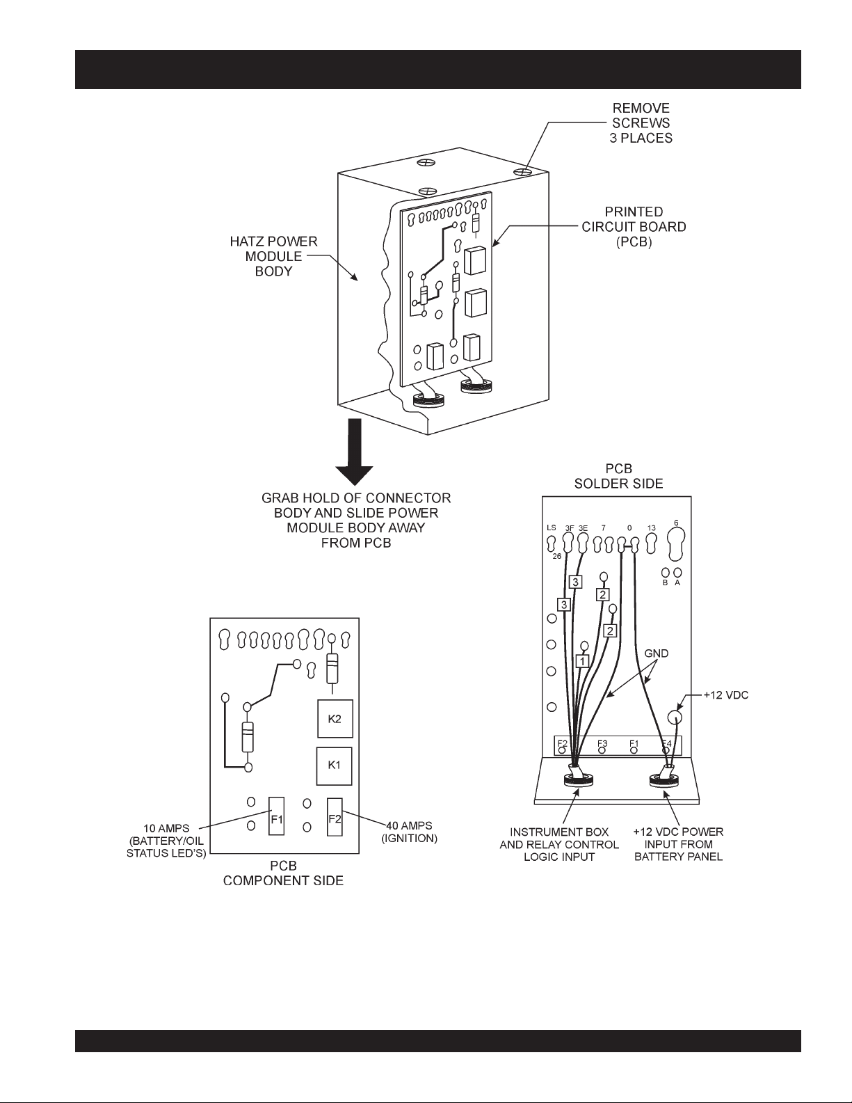
MG-30 PUMP — POWER MODULE LAYOUT
Figure 54. Power Module layout
MAYCO MG-30 PUMP — OPERATION AND PARTS MANUAL — REV. #3 (09/15/11) — PAGE 59
Page 60

EXPLANATION OF CODE IN REMARKS COLUMN
The following section explains the different symbols and
remarks used in the Parts section of this manual. Use the
help numbers found on the back page of the manual if there
are any questions.
NOTICE
The contents and part numbers listed in the parts
section are subject to change without notice. Multiquip
does not guarantee the availability of the parts listed.
SAMPLE PARTS LIST
NO. PART NO. PART NAME QTY. REMARKS
1 12345 BOLT ......................1 .....INCLUDES ITEMS W/%
2% WASHER, 1/4 IN. ...........NOT SOLD SEPARATELY
2% 12347 WASHER, 3/8 IN. ...1 .....MQ-45T ONLY
3 12348 HOSE ..................A/R ...MAKE LOCALLY
4 12349 BEARING ..............1 .....S/N 2345B AND ABOVE
NO. Column
Unique Symbols — All items with same unique
symbol
QTY. Column
Numbers Used — Item quantity can be indicated by a
number, a blank entry, or A/R.
A/R (As Required) is generally used for hoses or other
parts that are sold in bulk and cut to length.
A blank entry generally indicates that the item is not sold
separately. Other entries will be clarified in the “Remarks”
Column.
REMARKS Column
Some of the most common notes found in the “Remarks”
Column are listed below. Other additional notes needed
to describe the item can also be shown.
Assembly/Kit — All items on the parts list with the
same unique symbol will be included when this item is
purchased.
Indicated by:
“INCLUDES ITEMS W/(unique symbol)”
(@, #, +, %, or >) in the number column belong to the
same assembly or kit, which is indicated by a note in the
“Remarks” column.
Duplicate Item Numbers — Duplicate numbers indicate
multiple part numbers, which are in effect for the same
general item, such as different size saw blade guards in
use or a part that has been updated on newer versions
of the same machine.
NOTICE
When ordering a part that has more than one item
number listed, check the remarks column for help in
determining the proper part to order.
PART NO. Column
Numbers Used — Part numbers can be indicated by a
number, a blank entry, or TBD.
TBD (To Be Determined) is generally used to show a
part that has not been assigned a formal part number
at the time of publication.
A blank entry generally indicates that the item is not sold
separately or is not sold by Multiquip. Other entries will
be clarified in the “Remarks” Column.
Serial Number Break — Used to list an effective serial
number range where a particular part is used.
Indicated by:
“S/N XXXXX AND BELOW”
“S/N XXXX AND ABOVE”
“S/N XXXX TO S/N XXX”
Specific Model Number Use — Indicates that the part
is used only with the specific model number or model
number variant listed. It can also be used to show a
part is NOT used on a specific model or model number
variant.
Indicated by:
“XXXXX ONLY”
“NOT USED ON XXXX”
“Make/Obtain Locally” — Indicates that the part can
be purchased at any hardware shop or made out of
available items. Examples include battery cables, shims,
and certain washers and nuts.
“Not Sold Separately” — Indicates that an item cannot
be purchased as a separate item and is either part of an
assembly/kit that can be purchased, or is not available
for sale through Multiquip.
PAGE 60 — MAYCO MG-30 PUMP — OPERATION AND PARTS MANUAL — REV. #3 (09/15/11)
Page 61

MG-30 PUMP — SUGGESTED SPARE PARTS
ESSICK 120SM MIXER 1 TO 3 UNITS
WITH HATZ 1B30 DIESEL ENGINE
EM-120SM 1 TO 3 UNITS
Qty. P/N Description
1 ............ EM200293 ...... PADDLE ARM TOW SIDE
1 ............ EM200294 ...... PADDLE ARM CENTER TOW SIDE
1 ............ EM200295 ...... PADDLE ARM CENTER ENGINE SIDE
1 ............ EM200296 ...... PADDLE ARM ENGINE SIDE
3 ............ EM200863 ...... RUBBER BLADE KIT (STEEL DRUM)
2 ............ EM200297 ...... U-BOLT
2 ............ EM200268 ...... J-BOLT
2 ............ EM902153 ...... BEARING, PADDLE SHAFT
3 ............ EM963157 ...... CONNECTOR BOLT
1 ............ EM934041 ...... CLUTCH, DRIVEN MEMBER
12 .......... EM200301 ...... PACKING RINGS
4 ............ EM200286 ...... CARRIAGE BOLT
4 ............ EM200794 ...... ADJUSTMENT SPRING
4 ............ EM200285 ...... GLAND
2 ............ EM200303 ...... RING FOLLOWER
2 ............ 50449200 ........ GLOW PLUGS
3 ............ 50426000 ........ FILAMENT, AIR FILTER
3 ............ 01635200 ........ FUEL FILTER
3 ............ 50404900 ........ KEYS, IGNITION
1 ............ 50268600 ........ TEMP SWITCH
1 ............ 50469100 ........ OIL PRESSURE SWITCH
MG-30 PUMP (MOBILE AND TAG) 1 TO 3
UNITS WITH HATZ 2M41LZ DIESEL ENGINE
Qty. P/N Description
4 ............ EM402581 ...... QUARTER ROUND SEAL
6 ............ EM402580 ...... O-RING
2 ............ EM914312 ...... SEAL HOPPER
2 ............ EM400296 ...... PLUG, SAFETY PRESSURE RELEASE
4 ............ EM915003 ...... O-RING
4 ............ EM400581 ...... BLACK BALL PRESSURE RELEASE
2 ............ EM402421 ...... OILER PLATE
2 ............ EM402439 ...... STUD
2 ............ EM900227 ...... V-BELT TRANSMISSION
1 ............ EM900082 ...... V-BELT AIR COMPRESSOR
2 ............ EM400668 ...... CAP, NOZZLE
2 ............ EM400687 ...... 1/2" ORIFICE
2 ............ EM400688 ...... 9/16" ORIFICE
2 ............ EM400689 ...... 5/8" ORIFICE
3 ............ 40065300 ........ OIL FILTER
3 ............ 5031700 .......... PREFILTER, FUEL
3 ............ 50251500 ........ FUEL FILTER
3 ............ 50345700 ........ FUEL FILTER
3 ............ 00952900 ........ ELEMENT, AIR FILTER
1 ............ 50141500 ........ V-BELT
2 ............ 50163900 ........ GLOW PLUGS
1 ............ 40021300 ........ OIL PRESSURE SWITCH
1 ............ 50268600 ........ TEMP SWITCH
PLASTER/MORTAR
MODEL MG30-2 (2-INCH OUTLET) USED
ON CYLINDER DIAMETER OF 3.50"
1 TO 3 UNITS
Qty. P/N Description
2 ............ EM402394 ...... BACKUP WASHER
4 ............ EM402393 ...... LEATHER CUP
4 ............ EM402395 ...... FELT RING
4 ............ EM402392 ...... WASHER
4 ............ EM402390 ...... RUBBER EXPANDER WASHER
2 ............ EM402391 ...... EXPANDER INSERT
2 ............ EM402389 ...... COMPRESSION WASHER
4 ............ EM400581 ...... BLACK BALL
2 ............ EM402402 ...... VALVE SEAT W/PIN
2 ............ EM402415 ...... SLEEVE
2 ............ EM966089 ...... CAP SCREW
MODEL MG30-3 (3-INCH OUTLET) USED
ON CYLINDER DIAMETER OF 3.75"
1 TO 3 UNITS
Qty. P/N Description
4 ............ EM403004 ...... BACKUP WASHER
4 ............ EM403005 ...... LEATHER CUP
4 ............ EM403002 ...... FELT RING
4 ............ EM402390 ...... RUBBER EXPANDER WASHER
4 ............ EM403007 ...... EXPANDER WASHER
4 ............ EM403008 ...... COMPRESSION WASHER
4 ............ EM400581 ...... BALL STEEL
4 ............ EM402995 ...... VALVE SEAT W/O PIN
FIREPROOFING
MAYCO MG-30 PUMP — OPERATION AND PARTS MANUAL — REV. #3 (09/15/11) — PAGE 61
Page 62
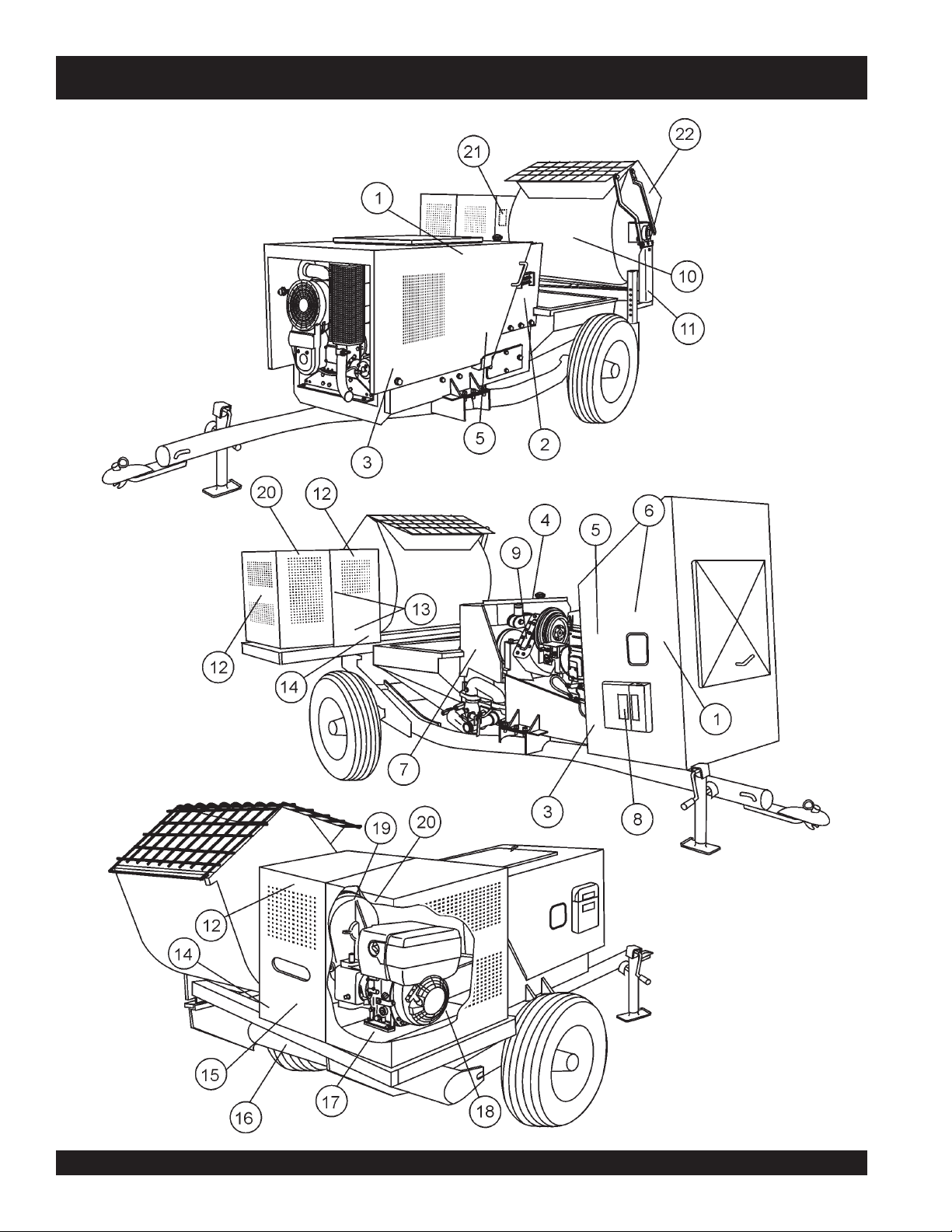
DECAL PLACEMENT
MG-30 PUMP — DECAL PLACEMENT
PAGE 62 — MAYCO MG-30 PUMP — OPERATION AND PARTS MANUAL — REV. #3 (09/15/11)
Page 63

MG-30 PUMP — DECAL PLACEMENT
PLACEMENT
NO. PART NO. PART NAME QTY. REMARKS
1 EM1028 DECAL, MQ MAYCO 2
2 EM513164 DECAL, GREASE DAILY 1
3 EM513159 DECAL, MG30-M2D ...................................... 2......... MOBILE UNIT ONLY
3 EM513158 DECAL, MG30-T2D ....................................... 2......... TAG UNIT ONLY
4 EM995 DECAL, USE DESIEL FUEL ONLY 1
5 EM508594 DECAL, CAUTION - READ MANUAL 2
6 EM513161 DECAL, CONTROL BOX 1
7 EM932 DECAL, CAUTION - MANIFOLD 1
8 34536 DECAL, OWNERS MANUAL 1
9 EM507607 DECAL, CAUTION- ADD OIL 1
10
11
12
13
14
15
16
17
18
19
20
21
22
EM510915 DECAL, MQ ESSICK LARGE 1
*
13118 DECAL, POWDER COATED ......................... 1......... MOBILE UNIT ONLY
*
TBD DECAL, MQ ESSICK SMALL ....................... 3 ......... MOBILE UNIT ONLY
*
EM948630 DECAL, PUSH TO STOP .............................. 2......... MOBILE UNIT ONLY
*
DCL151 DECAL, INSPECT BEFORE TOWING .......... 2......... MOBIE UNIT ONLY
*
EM948501 DECAL, ESSIC SAFTEY .............................. 1 ......... MOBILE UNIT ONLY
*
EM511709 DECAL, 800-30-MAYCO ................................ 1......... MOBILE UNIT ONLY
*
EM948005 DECAL, ENGINE OIL FILLER ....................... 1......... MOBILE UNIT ONLY
*
EM948012 DECAL, CLUTCH OIL FILLER ...................... 1......... MOBILE UNIT ONLY
*
EM948013 DECAL, TRANSMISSION OIL FILLER ......... 1......... MOBILE UNIT ONLY
*
DCL160A DECAL, WARNING - CRUSH/CUT HAZ. ....... 2......... MOBILE UNIT ONLY
*
EM948121 DECAL, IMPORTANT - PADDLE SHAFT ...... 1......... MOBILE UNIT ONLY
*
513479 DECAL, WARNING - SAFTEY GRATE .......... 1 ......... MOBILE UNIT ONLY
*
.................................................................................. PLACE ON INSIDE OF CABINET
MAYCO MG-30 PUMP — OPERATION AND PARTS MANUAL — REV. #3 (09/15/11) — PAGE 63
Page 64
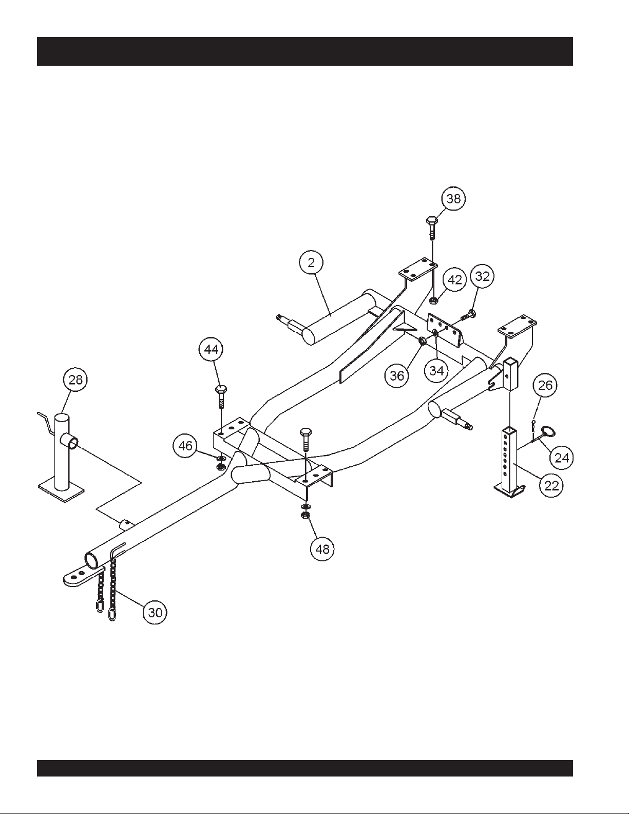
FRAME ASSY.
MG-30 PUMP — FRAME ASSY.
PAGE 64 — MAYCO MG-30 PUMP — OPERATION AND PARTS MANUAL — REV. #3 (09/15/11)
Page 65

MG-30 PUMP — FRAME ASSY.
FRAME ASSY.
NO. PART NO. PART NAME QTY. REMARKS
2 EM402975 TRAILER FRAME 1
22 EM70186 JACK STAND, REAR 1
24 EM744 PIN ASSEMBLY - 1/2” X 4” 1
26 EM745 COTTER PIN 1
28 EM25610 JACK STAND 1
30 EM01005 CONNECTOR LINKS 2
32 492394 HEX HEAD BOLT, 1/2 X 1-1/2 4
34 492600 WASHER 4
36 492584 HEX HEAD NUT 1/2 IN 4
38 EM963105 HEX HEAD BOLT 1/2 X 2 8
42 492584 HEX HEAD NUT 1/2 IN 8
44 EM492455 HEX HEAD BOLT 1/2 IN X 1-1/2 IN 6
46 EM621 WASHER 1/2 6
48 492584 HEX HEAD NUT 1/2 IN 6
MAYCO MG-30 PUMP — OPERATION AND PARTS MANUAL — REV. #3 (09/15/11) — PAGE 65
Page 66
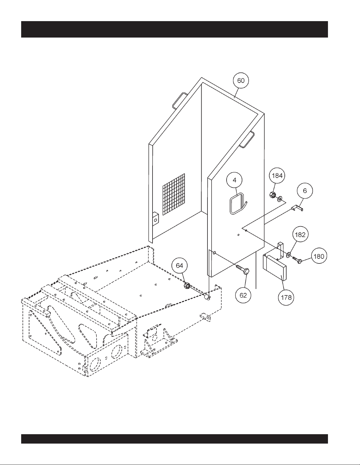
HOOD ASSY.
MG-30 PUMP — HOOD ASSY.
PAGE 66 — MAYCO MG-30 PUMP — OPERATION AND PARTS MANUAL — REV. #3 (09/15/11)
Page 67

MG-30 PUMP — HOOD ASSY.
HOOD ASSY.
NO. PART NO. PART NAME QTY. REMARKS
4 EM505831 GASKET 1
6 EM508659 LOCKING HANDLE 1
60 EM510830 HOUSING - MG 30 1
62 EM492399 HEX BOLT - 1/2 - 3 IN 2
64 492584 HEX NUT - 1/2 IN 2
178 29057 MANUAL HOLDER 1
180 492356 HEX BOLT - 1/4 X 3/4 IN 2
182 492596 FLAT WASHER - 1/4 IN 4
184 492581 HEX NUT - 1/4 IN 2
MAYCO MG-30 PUMP — OPERATION AND PARTS MANUAL — REV. #3 (09/15/11) — PAGE 67
Page 68
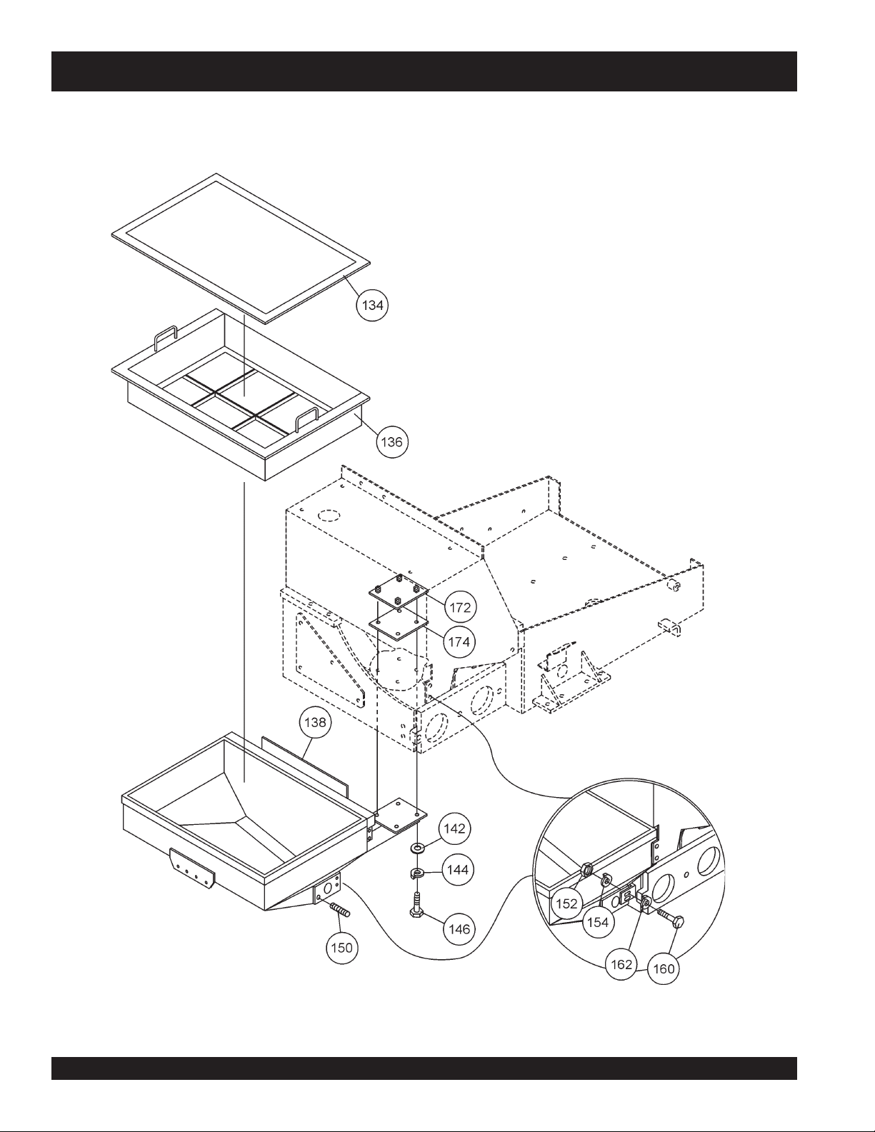
HOPPER ASSY.
MG-30 PUMP — HOPPER ASSY.
PAGE 68 — MAYCO MG-30 PUMP — OPERATION AND PARTS MANUAL — REV. #3 (09/15/11)
Page 69

MG-30 PUMP — HOPPER ASSY.
HOPPER ASSY.
NO. PART NO. PART NAME QTY. REMARKS
134 EM402521 HOPPER SCREEN 1
136 EM402519 HOPPER SCREEN FRAME 1
138 EM402495 HOPPER 1
142 EM621 WASHER - 1/2 IN 4
144 6109180 LOCK WASHER - 1/2 IN 4
146 EM963105 HEX BOLT - 1/2 X 2 IN 4
148 EM963057 HEX BOLT - 3/8 X 1-1/8 IN 2
150 EM402422 STUD - 3/4 X 2-1/8 IN 1
152 1456 HEX NUT - 3/8 IN 2
154 0166 A LOCK WASHER - 3/8 IN 2
160 EM963057 HEX BOLT - 3/8 X 1-1/2 IN 2
172 EM513149 ANCORING PLATE W/ NUT 1
174 EM513151 SEAL PLATE 1
MAYCO MG-30 PUMP — OPERATION AND PARTS MANUAL — REV. #3 (09/15/11) — PAGE 69
Page 70
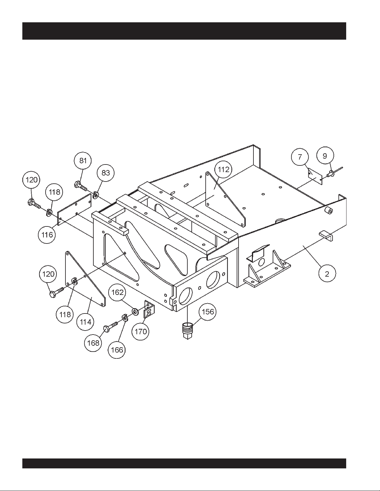
CHASSIS ASSY.
MG-30 PUMP — CHASSIS ASSY.
PAGE 70 — MAYCO MG-30 PUMP — OPERATION AND PARTS MANUAL — REV. #3 (09/15/11)
Page 71

MG-30 PUMP — CHASSIS ASSY.
CHASSIS ASSY.
NO. PART NO. PART NAME QTY. REMARKS
2 EM402447 FRAME - MG30 1
7 PLATE - SERIAL NO. ............................1 .............. ORDER FROM MQ PARTS DEPT.
WITH MODEL AND SERIAL NO.
9 491757 POP RIVETS 2
81 EM963692 HEX BOLT - 1/2 X 1-1/8 IN 3
83 6109180 LOCK WASHER 1/2 IN 3
112 EM511044 PLATE - SMALL 1
114 EM511042 PLATE FRONT 1
116 EM511046 PLATE 1
118 0166A LOCK WASHER - 3/8 IN 12
120 492309 HEX BOLT - 3/8 X 3/4 IN 12
156 507895 PLUG - 2-1/2 IN 1
162 3019092 WASHER - 3/8 IN 6
164 EM969013 HEX NUT - 3/8 IN 2
168 EM963610 HEX BOLT - 3/8 X 1 IN 2
170 EM402515 MOUNTING BRACKET 1
MAYCO MG-30 PUMP — OPERATION AND PARTS MANUAL — REV. #3 (09/15/11) — PAGE 71
Page 72

COMPRESSOR ASSY.
MG-30 PUMP — COMPRESSOR ASSY.
PAGE 72 — MAYCO MG-30 PUMP — OPERATION AND PARTS MANUAL — REV. #3 (09/15/11)
Page 73

MG-30 PUMP — COMPRESSOR ASSY.
COMPRESSOR ASSY.
NO. PART NO. PART NAME QTY. REMARKS
4 EM510827 COMPRESSOR BASE 1
6 EM963059 HEX BOLT - 3/8 X 1 - 1/4 IN 4
8 3019092 WASHER - 3/8 IN 8
10 0166 A LOCK WASHER - 3/8 IN 4
11 492486 ADJUSTING BOLT - 3/8 X 1 - 3/8 IN 1
12 1456 HEX NUT - 3/8 IN 8
14 510707 BOLTING BAR 2
16 492365 HEX BOLT - 5/16 X 1 - 1/4 IN 4
18 EM923343 LOCK WASHER - 5/16 IN 4
20 EM958171 COMPRESSOR, AIR 1
22 EM958033 AIR FILTER 1
24 EM911058 ELBOW 90° 1
26 EM402489 AIR TANK 1
28 EM508695 AIR HOSE 1
30 EM913116 SAFETY VALVE 1
32 EM963610 BOLT HEX - 3/8 X 1 IN 3
34 0166 A LOCK WASHER - 3/8 IN 3
38 EM491260 ELBOW ADAPTER MALE - 90° 1
40 512609 ADAPTER REDUCER FEMALE ............ 1 .................. 1/8” TO 5/16”
42 EM947032 QUICK-CONNECT SIGET - MALE 1
128 492356 HEX BOLT - 1/4 X 3/4 IN 1
130 2101402 LOCK WASHER - 1/4 IN 1
131 492596 WASHER - 1/4 IN 2
132 351104770 BRACKET -3/4 IN 1
MAYCO MG-30 PUMP — OPERATION AND PARTS MANUAL — REV. #3 (09/15/11) — PAGE 73
Page 74
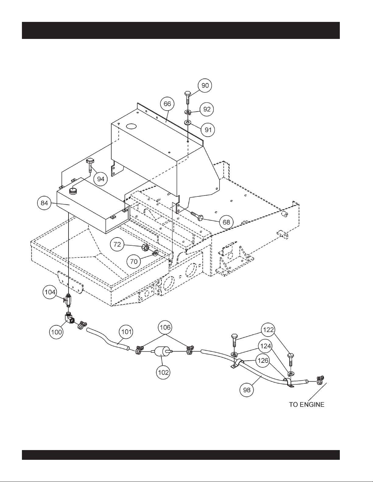
FUEL TANK ASSY.
MG-30 PUMP — FUEL TANK ASSY.
PAGE 74 — MAYCO MG-30 PUMP — OPERATION AND PARTS MANUAL — REV. #3 (09/15/11)
Page 75

MG-30 PUMP — FUEL TANK ASSY.
FUEL TANK ASSY.
NO. PART NO. PART NAME QTY. REMARKS
66 EM402532 BONNET 1
68 EM963692 HEX BOLT 1/2 X 1 - 1/8 IN 5
70 6109180 LOCK WASHER 1/2 IN 5
72 6109160 HEX NUT 1/2 IN 5
84 EM402494 FUEL TANK, W/CAP ..............................1 .................. INCLUDES ITEMS W/
90 EM963610 HEX BOLT 3/8 X 1 IN 4
91 3019092 WASHER - 3/8 IN 4
92 0166 A LOCK WASHER - 3/8 IN 4
94
98 EM20427 TUBING 1
100 EM20426 ELBOW 90° - 1/8 IN 1
101 EM20427 TUBING 1
102 EM20763 FUEL FILTER 1
104 EM20421 VALVE, SHUT-OFF 1
106 506208 CLAMP - 1/4 IN 3
122 492356 HEXBOLT - 1/4 X 3/4 IN 2
124 2101402 LOCK WASHER - 1/4 IN 2
126 EM503081 BRACKET - 1/4 IN 2
19340 FUEL TANK CAP W /GAUGE 1
*
*
MAYCO MG-30 PUMP — OPERATION AND PARTS MANUAL — REV. #3 (09/15/11) — PAGE 75
Page 76

PISTON OILER TANK ASSY.
MG-30 PUMP — PISTON OILER TANK ASSY.
PAGE 76 — MAYCO MG-30 PUMP — OPERATION AND PARTS MANUAL — REV. #3 (09/15/11)
Page 77

MG-30 PUMP — PISTON OILER TANK ASSY.
PISTON OILER TANK ASSY.
NO. PART NO. PART NAME QTY. REMARKS
74 310555 OIL TANK W/ BRACKETS 1
76 492356 HEX BOLT - 1/4 X 3/4 IN 4
78 492596 WASHER 1/4 IN 2
80 2101402 LOCK WASHER 1/4 IN 4
82 492561 HEX NUT 1/4 IN 2
86 512722 VALVE, SHUT-OFF 1
87 EM20415 TUBING 1
88 512731 MALE CONNECTOR REDUCER ...........1 .................. 1/8 TO 5/16
89 512721 TEE CONNETOR 1
93 EM20426 ELBOW 90° 1
95 513116 BRACKET - 1/2 IN 1
99 492561 HEX NUT - 1/4 IN 2
MAYCO MG-30 PUMP — OPERATION AND PARTS MANUAL — REV. #3 (09/15/11) — PAGE 77
Page 78
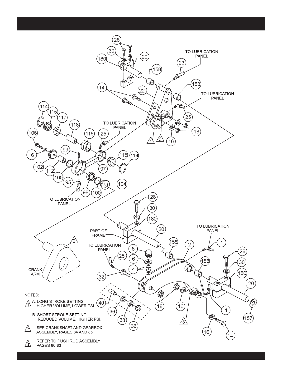
ROCKER ARM ASSY.
MG-30 PUMP — ROCKER ARM ASSY.
PAGE 78 — MAYCO MG-30 PUMP — OPERATION AND PARTS MANUAL — REV. #3 (09/15/11)
Page 79

MG-30 PUMP — ROCKER ARM ASSY.
ROCKER ARM ASSY.
NO. PART NO. PART NAME QTY. REMARKS
1 EM505490 FITTING 45° - 1/8 TO 7/16 IN 2
2 EM402982 CAM ROCKER 1
4 EM402456 OILER FELT 2
6 EM607 WASHER - 1/2 IN 1
8 EM20349 OIL CAP 1
14 512613 HEX BOLT - 1 X 5 IN 3
16 EM603 LOCK WASHER - 1 IN 3
18 EM417 HEX NUT - 1 IN 3
20 EM20339 ROCKER ARM SHAFT 1
22 EM402464 CRANK ROCKER ARM W/ BUSHING 1
23 EM505489 CONNECTOR - 1/8 IN TO 7/16 IN 1
25 EM505491 ELBOW 45° - 1/8 IN TO 7/16 IN 1
28 505124 HEX BOLT 3/4" X 5" G5 4
30 492628 LOCK WASHER - 3/4 IN 6
32 EM20344 GREASING BOLT 1
36 EM20347 BEARING SPACER 2
38 EM903092 BEARING ASSEMBLY 1
40 EM402434 BEARING BUSHING 1
95 EM505489 CONNECTOR MALE 1
97 EM514328 SP CONECTING ROD 1
98 EM903176 BEARING 1
99 EM702 SCREW ALLEN HEAD 3/8-16 X 3/4" 1
100 EM20336 O -RING 2
102 EM402996 SEAL PLATE 1
104 EM402997 SEAL PLATE 1
106 EM104 HEX BOLT - 5/8 X 2 IN 1
114 EM20816 O -RING 2
115 EM903162 CONE BEARING 2
116 EM903163 BEARING CUP 1
117 EM20813 SPACER 1
118 EM20814 BEARING BUSHING 1
157 512854 WASHER - 5/8 IN 1
158 EM402461 BUSHINGS 4
180 EM402457 BLOCK 3
MAYCO MG-30 PUMP — OPERATION AND PARTS MANUAL — REV. #3 (09/15/11) — PAGE 79
Page 80

PUSH ROD (3.5-INCH) ASSY.
CAUTION:
This assembly drawing is intended to
be used with
NOTE
MG30T-2 Models, using
Mortar
3.5-inch (90 mm) cylinders.
MG-30 PUMP — PUSH ROD (3.5-INCH) ASSY.
ONLY
the MG30M-2 and
Plaster
materials. This application uses
and
PAGE 80 — MAYCO MG-30 PUMP — OPERATION AND PARTS MANUAL — REV. #3 (09/15/11)
Page 81

MG-30 PUMP — PUSH ROD (3.5-INCH) ASSY.
PUSH ROD (3.5-INCH) ASSY.
NO. PART NO. PART NAME QTY. REMARKS
44 EM402437 PUSH ROD 2
46 EM402441 BEARING HOUSING 2
48 EM492421 HEX BOLT - 3/4 X 3 - 1/2 IN 2
50 EM969038 HEX NUT - 3/4 IN 2
52 EM20816 O-RING 2
54 EM903162 BEARING CONE 2
56 EM903163 BEARING CUP 2
58 EM20813 BEARING SPACER 2
60 EM20814 BEARING BUSHING 2
62 EM903162 BEARING CONE 2
64 EM20816 O-RING 2
66 EM491056 O-RING 2
68 EM402421 FELT OILER PLATE 2
70 EM402395 FELT WASHER 2
72 EM402396 SPACER 2
74 EM491056 O-RING 2
76 EM402394 BACK- UP WASHER 2
78 EM402393 LEATHER CUP 2
80 EM402392 CUP WASHER 2
82 EM402390 EXPANDER WASHER 2
84 EM402391 EXPANDER INSERT 2
86 EM402389 COMPRESION WASHER 2
88 EM402439 STUD - 1/2 X 3 - 5/16 IN 2
90 6109160 HEX NUT - 1/2 IN 4
92 EM20415 TUBING - 3/16 IN x 5' 2
CAUTION:
NOTE
MAYCO MG-30 PUMP — OPERATION AND PARTS MANUAL — REV. #3 (09/15/11) — PAGE 81
This parts list is intended to be used
with
ONLY
the MG30M-2 and MG30T2 Models, using
materials. This application uses 3.5-
inch (90 mm) cylinders.
Plaster
and
Mortar
Page 82
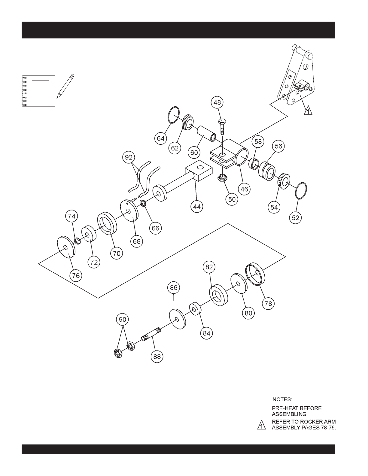
PUSH ROD (3.75-INCH) ASSY.
CAUTION:
This assembly drawing is intended to
be used with
NOTE
MG30T-3 Models, using
materials. This application uses 3.75-
inch (95.25 mm) cylinders.
MG-30 PUMP — PUSH ROD (3.75-INCH) ASSY.
ONLY
the MG30M-3 and
Fireproofing
PAGE 82 — MAYCO MG-30 PUMP — OPERATION AND PARTS MANUAL — REV. #3 (09/15/11)
Page 83

MG-30 PUMP — PUSH ROD (3.75-INCH) ASSY.
PUSH ROD (3.75-INCH) ASSY.
NO. PART NO. PART NAME QTY. REMARKS
44 EM402437 PUSH ROD 2
46 EM402441 BEARING HOUSING 2
48 EM492421 HEX BOLT - 3/4 X 3 - 1/2 IN 2
50 EM969038 HEX NUT - 3/4 IN 2
52 EM20816 O-RING 2
54 EM903162 BEARING CONE 2
56 EM903163 BEARING CUP 2
58 EM20813 BEARING SPACER 2
60 EM20814 BEARING BUSHING 2
62 EM903162 BEARING CONE 2
64 EM20816 O-RING 2
66 EM491056 O-RING 2
68 EM402421 FELT OILER PLATE 2
70 EM403002 FELT WASHER 2
72 EM402396 SPACER 2
74 EM915003 O-RING 2
76 EM403004 BACK- UP WASHER 2
78 EM403005 LEATHER CUP 2
80 EM403006 CUP WASHER 2
82 EM403007 EXPANDER WASHER 2
84 EM402391 EXPANDER INSERT 2
86 EM403008 COMPRESION WASHER 2
88 EM402439 STUD - 1/2 X 3 - 5/16 IN 2
90 EM968003 HEX NUT - 1/2 IN 4
92 EM20415 TUBING - 3/16 IN x 5' 2
CAUTION:
NOTE
MAYCO MG-30 PUMP — OPERATION AND PARTS MANUAL — REV. #3 (09/15/11) — PAGE 83
This parts list is intended to be used
with
ONLY
the MG30M-3 and MG30T3 Models, using
materials. This application uses 3.5-
inch (90 mm) cylinders.
Fireproofing
Page 84
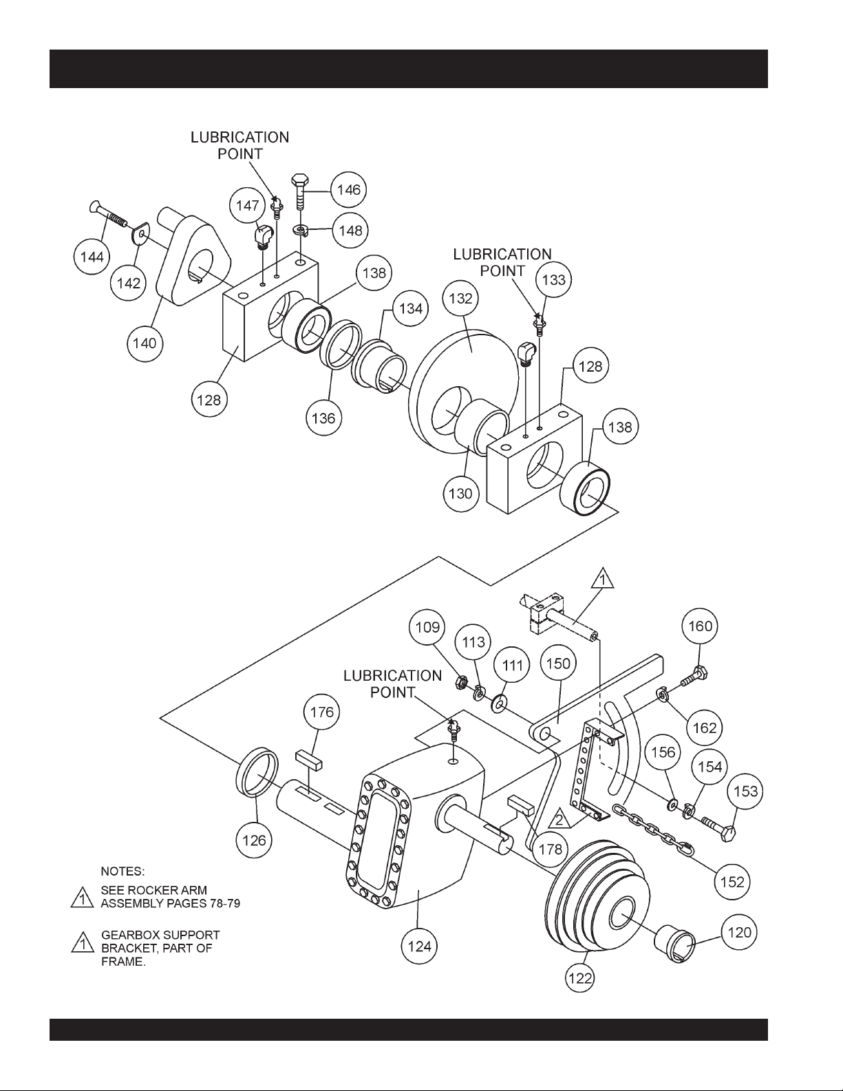
MG-30 PUMP — CRANKSHAFT AND GEAR BOX ASSY.
CRANKSHAFT AND GEAR BOX ASSY.
PAGE 84 — MAYCO MG-30 PUMP — OPERATION AND PARTS MANUAL — REV. #3 (09/15/11)
Page 85

MG-30 PUMP — CRANKSHAFT AND GEAR BOX ASSY.
CRANKSHAFT AND GEAR BOX ASSY.
NO. PART NO. PART NAME QTY. REMARKS
109 EM492570 HEX NUT - 5/8 IN 1
110 EM417 HEXNUT - 1 IN 1
111 EM505882 WASHER - 5/8 1
112 EM402998 ADAPTER SLEEVE 1
113 EM492627 LOCK WASHER - 5/8 IN 1
120 EM901331 BUSHING 1
122 EM400090 STEP PULLEY 1
124 EM931000 GEAR BOX 1
126 EM510847 SPACER - 3 IN , 9MM 1
128 EM20324-1 BLOCK BEARING 2
130 EM510846 SPACER - 3 IN , 47.5 MM 1
132 EM20301 CAM 1
133 EM702 SCREW ALLEN HEAD 3/8-16 X 3/4 2
134 EM20303 BUSHING 1
136 EM510845 SPACER - 3 IN , 12 MM 1
138 EM20324-2 BEARING 2
140 EM402412 CRANK 1
142 EM402413 TENSION WASHER W /SLOT 1
144 EM512618 ALLEN BOLT - 1/2 X 2 IN 1
146 EM505122 HEX BOLT - 3/4 X 8 - 1/2 IN 4
147 EM505490 ELBOW 45° 2
148 EM492628 LOCK WASHER - 1 IN 4
150 EM20306 BELT TIGHTENER 1
152 EM509947 MASTER LINK W/CHAIN 1
153 EM503982 HEX BOLT- 5/8 X 2 IN 1
154 EM923348 LOCK WASHER - 5/8 IN 1
156 EM402459 GROOVE WASHER 1
160 EM492363 HEX BOLT - 5/16 X 3/4 IN 8
162 EM492623 LOCK WASHER - 5/16 8
176 EM513233 KEY - 3/4 X 5/8 X 1 - 3/4 IN 2
178 EM513232 KEY - 3/8 IN X 65 MM 1
MAYCO MG-30 PUMP — OPERATION AND PARTS MANUAL — REV. #3 (09/15/11) — PAGE 85
Page 86
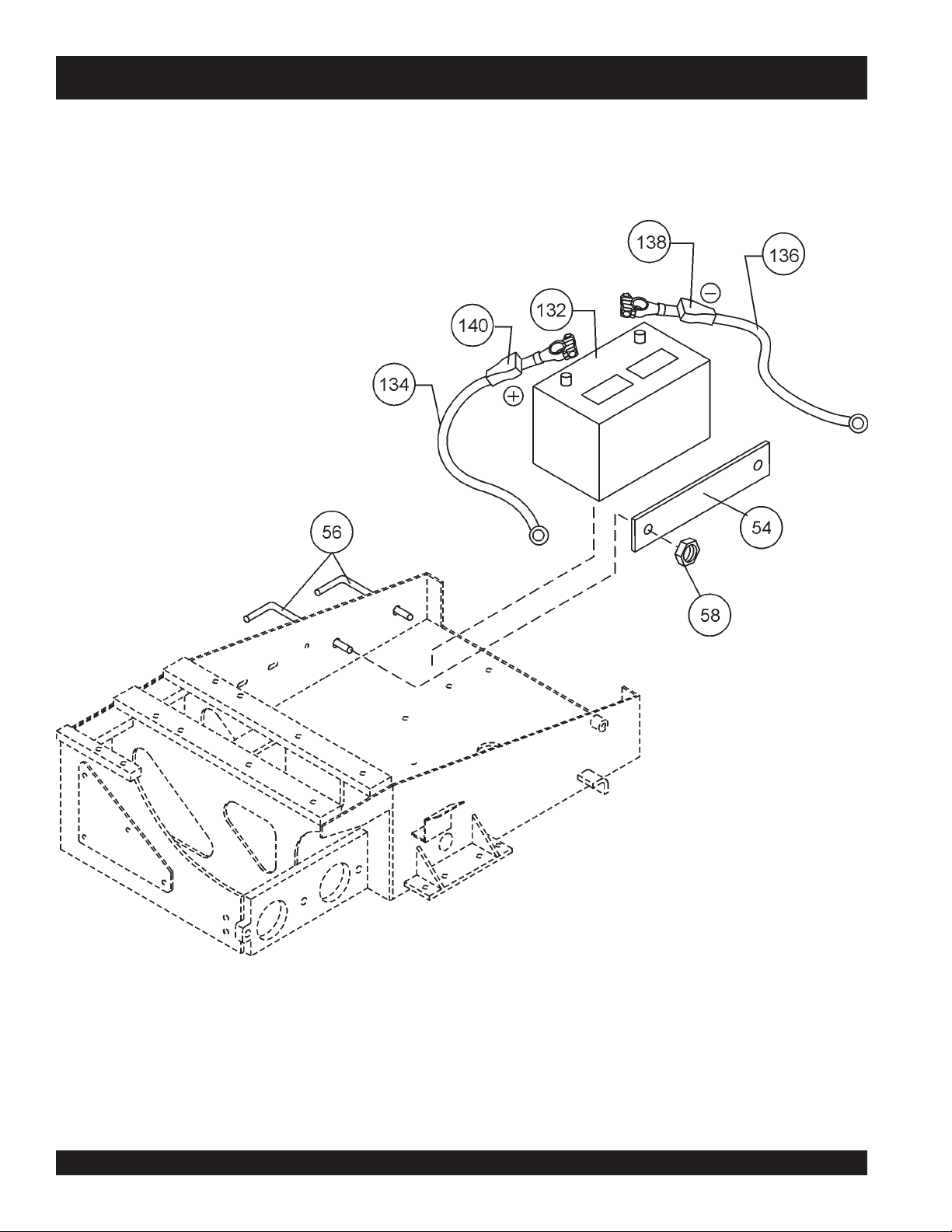
BATTERY ASSY.
MG-30 PUMP — BATTERY ASSY.
PAGE 86 — MAYCO MG-30 PUMP — OPERATION AND PARTS MANUAL — REV. #3 (09/15/11)
Page 87

MG-30 PUMP — BATTERY ASSY.
BATTERY ASSY.
NO. PART NO. PART NAME QTY. REMARKS
54 EM510708 BATTERY CLAMP 1
56 EM510844 SUPORT ROD 1
58 EM969079 HEX NUT - 1/4 IN 1
132 507590 BATTERY - 12 V 1
134 EM505297 BATTERY TERMINAL CABLE - POS. 1
136 EM20720 BATTERY TERMINAL CABLE - NEG. 1
138 505624 BATTERY TERMINAL COVER - BLACK 1
140 506266 BATTERY TERMINAL COVER - RED 1
MAYCO MG-30 PUMP — OPERATION AND PARTS MANUAL — REV. #3 (09/15/11) — PAGE 87
Page 88
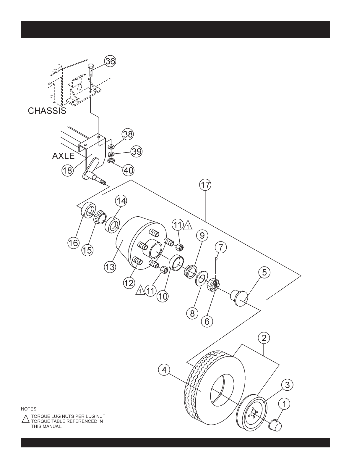
TAG UNIT AXLE ASSY.
MG-30 PUMP— TAG UNIT AXLE ASSY.
PAGE 88 — MAYCO MG-30 PUMP — OPERATION AND PARTS MANUAL — REV. #3 (09/15/11)
Page 89

MG-30 PUMP— TAG UNIT AXLE ASSY.
TAG UNIT AXLE ASSY.
NO. PART NO. PART NAME QTY. REMARKS
1 EM26518 CAP 14” CHROME 2
2 EM26615A TIRE ASSY. ................................ 2 ........... INCLUDES ITEMS W/
3
4
5#$ EM26306 DUST COVER 2
6#$ EM968481 CASTLE NUT 2
7 EM705 PIN, COTTER 3/16X1 1/2 2
8#$ EM26329 WASHER 2
9#$ EM903113 OUTER BEARING 2
10#$ EM903012 OUTER CUP 2
11#$ EM26519 NUT 12
12#$ EM20612 STUD 12
13#$ EM26300 HUB 2
14#$ EM903169 INNER CUP 2
15#$ EM903168 INNER BEARING 2
16#$ EM26305 GREASE SEAL 2
17$ EM20601 HUB ASSEMBLY ........................ 2 ........... INCLUDES ITEMS W/#
18 EM14600 AXLE 1
18 EM14600A AXLE WITH HUB INSTALLED .... 1 ........... INCLUDES ITEMS W/$
EM20602 WHEEL ....................................... 2 ........... CANNOT BE PURCHASED SEPARATELY
*
EM20603 TIRE ........................................... 2 ........... CANNOT BE PURCHASED SEPARATELY
*
*
MAYCO MG-30 PUMP — OPERATION AND PARTS MANUAL — REV. #3 (09/15/11) — PAGE 89
Page 90
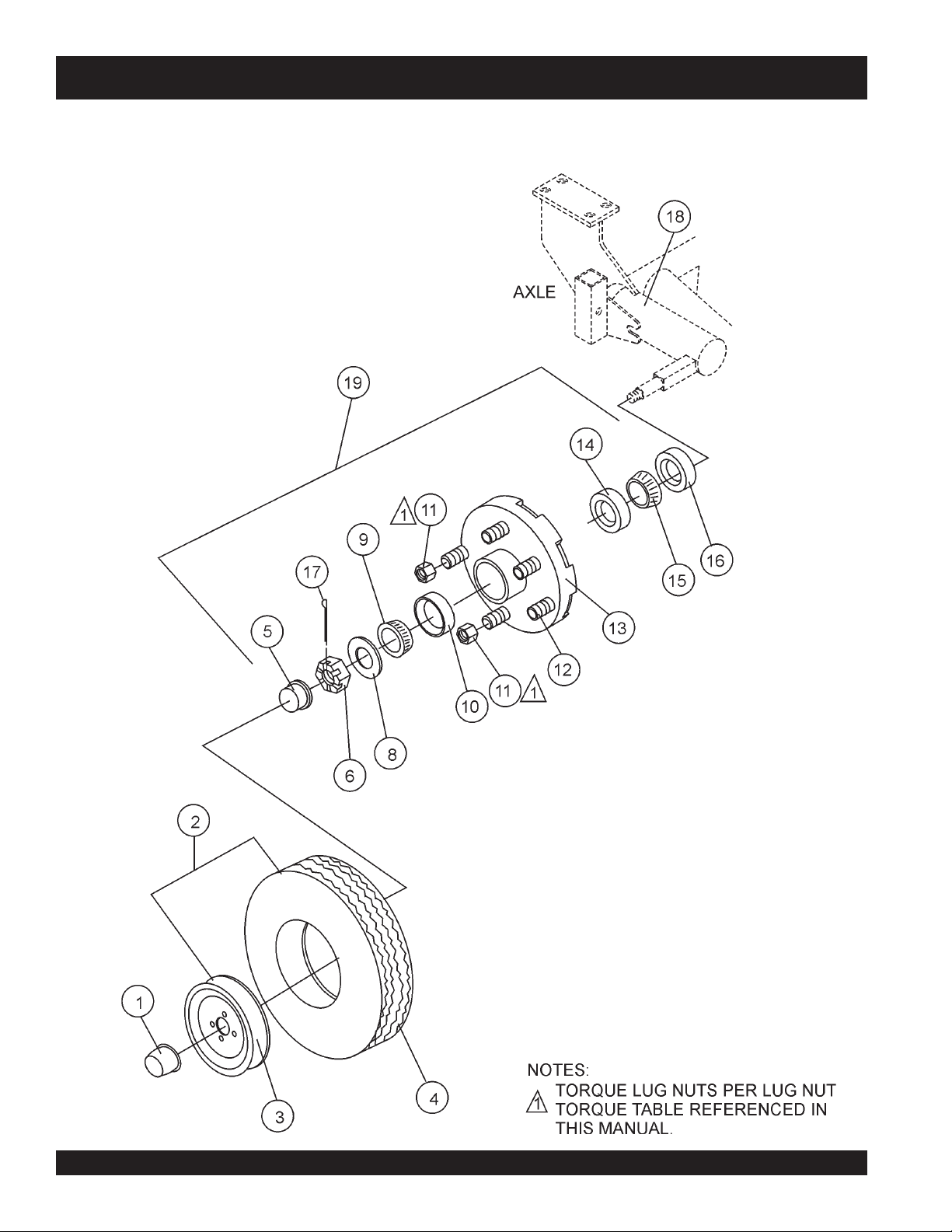
MOBLE UNIT AXLE ASSY.
MG-30 PUMP — MOBILE UNIT AXLE ASSY.
PAGE 90 — MAYCO MG-30 PUMP — OPERATION AND PARTS MANUAL — REV. #3 (09/15/11)
Page 91

MG-30 PUMP — MOBILE UNIT AXLE ASSY.
MOBLE UNIT AXLE ASSY.
NO. PART NO. PART NAME QTY. REMARKS
1 EM26520 CAP 15” CHROME 2
2 EM26615 TIRE ASSY. ................................ 2 ........... INCLUDES ITEMS W/
3
*
4
*
5# EM941307 DUST CAP 2
6#$ CASTLE NUT ............................. 2 ........... INCLUDES ITEMS W/$
8#$ WASHER .................................... 2 ........... CANNOT BE PURCHASED SEPARATELY
9# EM941309 OUTER BEARING 2
10# EM941315 OUTER CUP 2
11# EM941314 NUT 12
12# EM941315 STUD 12
13# HUB ............................................ 2 ........... CANNOT BE PURCHASED SEPARATELY
14# EM941310 INNER CUP 2
15# EM941312 INNER BEARING 2
16# EM941311 GREASE SEAL 2
17#$ PIN, COTTER 3/16X1 1/2 ........... 2 ........... CANNOT BE PURCHASED SEPARATELY
18 TBD AXLE .......................................... 1 ........... CONTACT MULTIQUIP PARTS DEPT.
19 EM512906 HUB ASSEMBLY ........................ 2 ........... INCLUDES ITEMS W/#
WHEEL ....................................... 2 ........... CANNOT BE PURCHASED SEPARATELY
TIRE ........................................... 2 ........... CANNOT BE PURCHASED SEPARATELY
*
MAYCO MG-30 PUMP — OPERATION AND PARTS MANUAL — REV. #3 (09/15/11) — PAGE 91
Page 92
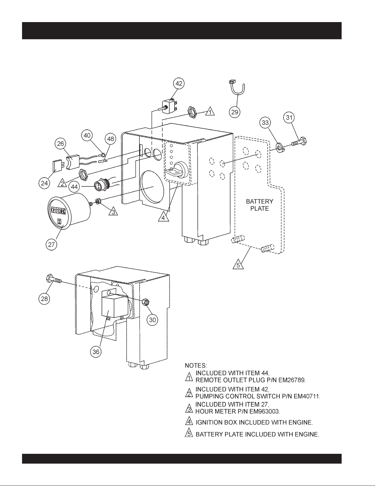
CONTROL BOX ASSY.
MG-30 PUMP — CONTROL BOX ASSY.
PAGE 92 — MAYCO MG-30 PUMP — OPERATION AND PARTS MANUAL — REV. #3 (09/15/11)
Page 93

MG-30 PUMP — CONTROL BOX ASSY.
CONTROL BOX ASSY.
NO. PART NO. PART NAME QTY. REMARKS
24 508632 FUSE, 25 AMP 1
26 EM98066 FUSE HOLDER 1
27 EM18706 HOURMETER 1
28 EM963003 HEX BOLT - 1/4 X 3/4 IN 1
29 504505 CABLE TIE WRAP 3
30 EM969079 HEX NUT - 1/4 IN 1
31 EM506599 HEX BOLT - 6MM X 15 3
32 EM512644 INSTRUMENT PANEL 1
33 2101402 LOCK WASHER - 1/4 IN 1
36 EM16710 RELAY 1
40 EM491897 TERMINAL - BLUE 3/16 LOOP 1
42 EM40711 SWITCH 1
44 EM26789 RECEPTICAL FEMALE 1
46 EM491879 STAR NUT FOR RECEPTICAL 1
48 EM508242 CONNECTOR 1
MAYCO MG-30 PUMP — OPERATION AND PARTS MANUAL — REV. #3 (09/15/11) — PAGE 93
Page 94
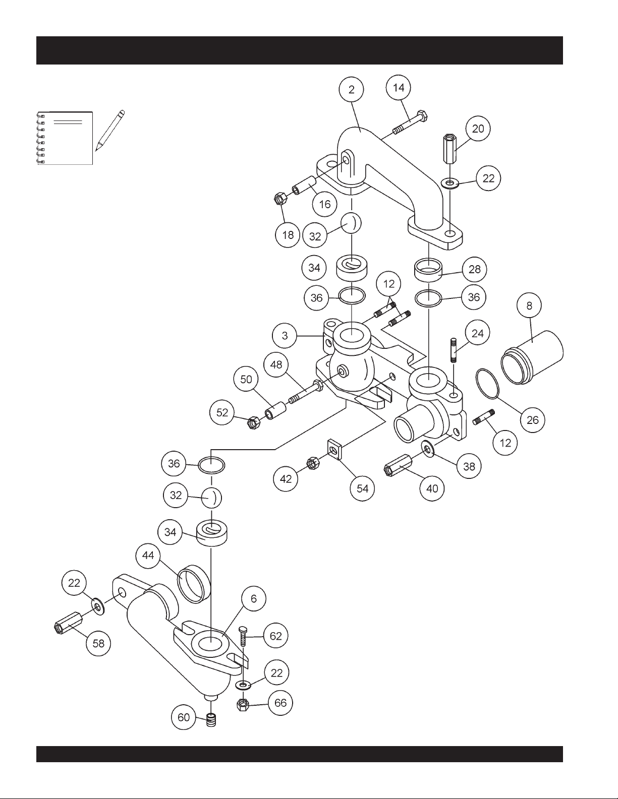
MG-30 PUMP — MANIFOLD (2-INCH OUTLET) ASSY.
MANIFOLD (2-INCH OUTLET) ASSY.
This assembly drawing is intended to
NOTE
be used with
MG30T-2 Models, using
Mortar
a 2.0-inch (50.8 mm) outlet.
ONLY
materials. This application uses
the MG30M-2 and
Plaster
and
PAGE 94 — MAYCO MG-30 PUMP — OPERATION AND PARTS MANUAL — REV. #3 (09/15/11)
Page 95

MG-30 PUMP — MANIFOLD (2-INCH OUTLET) ASSY.
MANIFOLD (2-INCH OUTLET) ASSY.
NO. PART NO. PART NAME QTY. REMARKS
2 EM402385 CONNECTING MANIFOLD 1
3 EM402383 PUMP MANIFOLD 2-INCH 45 OUTLET ...... 1 .......... (TAG UNIT)
3 EM402382 PUMP MANIFOLD 2 -INCH STR. OUTLET . 1 .......... (MOBILE UNIT)
6 EM402388 HOPPER ELBOW 1
8 EM403408 MATERIAL CYLINDER 3.5" DIA ................... 2 .......... STANDARD
12 EM402977 STUD - 1 X 5-1/2 IN 3
14 EM503111 CAP SCREW 1/2 X 4 - 1/2 IN 1
16 EM402473 SLEEVE FOR FIREPROOF KIT 1
18 EM492584 HEX NUT 1/2 IN 1
20 EM968002 HEX NUT 3/4 IN 2
22 EM619 WASHER 3/4 IN 5
24 EM510849 STUD - 3/4 X 3 IN 2
26 EM402581 QUARTER ROUND SEAL 2
28 EM402418 CONNECTING RING 1
32 EM400581 RUBBER BALL 2
34 EM402402 VALVE SEAT WITH PIN 2
36 EM402580 SPECIAL O - RING 3
38 EM512914 WASHER - 1 IN 2
40 EM968020 HEX NUT - 1 IN 2
42 EM512612 HEX NUT - 1 IN 1
44 EM914312 SEAL 1
48 EM492399 CAP SCREW - 1/2 X 3 IN 1
50 EM402415 SLEEVE SHORT 1
52 EM492584 HEX NUT - 1/2 IN 1
54 EM402986 SQUARE WASHER - 1 IN 1
58 EM968002 HEX NUT - 3/4 IN 1
60 EM505988 PIPE PLUG - 1 IN 1
62 EM966207 “T” SLOT BOLT - 1/2 IN X 2 - 1/4 IN 2
66 EM492556 HEX NUT - 1/2 IN 2
NOTE
This parts list is intended to be used with
ONLY
the MG30M-2 and MG30T-2 Models,
using
Plaster
application uses a 2.0-inch (50.8 mm)
outlet.
MAYCO MG-30 PUMP — OPERATION AND PARTS MANUAL — REV. #3 (09/15/11) — PAGE 95
and
Mortar
materials. This
Page 96
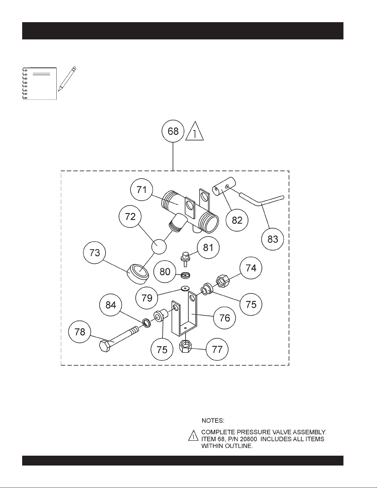
MG-30 PUMP — PRESSURE RELIEF VALVE (2-INCH OUTLET) ASSY.
PRESSURE RELIEF VALVE (2-INCH OUTLET) ASSY.
This assembly drawing is intended to
NOTE
be used with
MG30T-2 Models, using
Mortar
a 2.0-inch (50.8 mm) outlet.
ONLY
the MG30M-2 and
Plaster
materials. This application uses
and
PAGE 96 — MAYCO MG-30 PUMP — OPERATION AND PARTS MANUAL — REV. #3 (09/15/11)
Page 97

MG-30 PUMP — PRESSURE RELIEF VALVE (2-INCH OUTLET) ASSY.
PRESSURE RELIEF VALVE (2-INCH OUTLET) ASSY.
NO. PART NO. PART NAME QTY. REMARKS
68 EM20800 PRESSURE RELIEF - 2 IN ......................... 1 .......... INCLUDES ITEMS ITEMS W/
71
72
73
73
74
75
76
77
78
79
80
81
82
83
84
EM20800 BODY ASSEMBLY 2 IN 1
*
EM400581 RUBBER BALL 1
*
EM402527 WORKING PRESSURE CAP 700# 1
*
EM402528 WORKING PRESSURE CAP 1000# 1
*
EM969079 LOCK NUT 1
*
EM906065 BUSHING 2
*
EM20807 CLAMPING YOKE 2 IN 1
*
EM969079 LOCK NUT 1
*
EM963518 CAP SCREW 2 IN 1
*
EM400714 SHIM WASHER 1
*
EM400458 CAP 1
*
EM20806 SAFTEY PLUG 1
*
EM20803 CAM 2 IN 1
*
EM20805 CAM LEVER 1
*
TBD WASHER 1
*
*
NOTE
This parts list is intended to be used with
ONLY
the MG30M-2 and MG30T-2 Models,
using
Plaster
application uses a 2.0-inch (50.8 mm)
outlet.
and
Mortar
materials. This
MAYCO MG-30 PUMP — OPERATION AND PARTS MANUAL — REV. #3 (09/15/11) — PAGE 97
Page 98
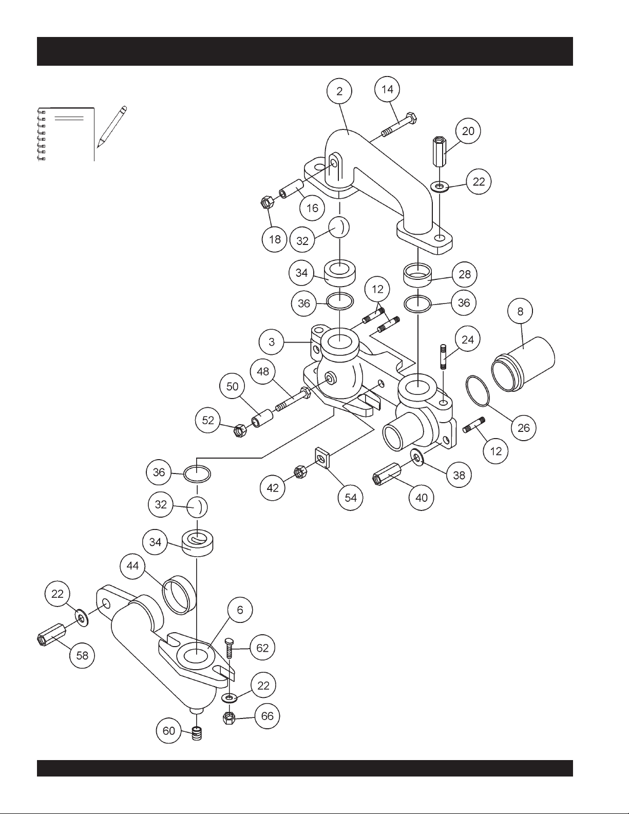
MG-30 PUMP — MANIFOLD (3-INCH OUTLET) ASSY.
MANIFOLD 3-INCH OUTLET) ASSY.
This assembly drawing is intended to
NOTE
be used with
MG30T-3 Models, using
materials. This application uses a 3.0-
inch (76.2 mm) outlet.
ONLY
the MG30M-3 and
Fireproofing
PAGE 98 — MAYCO MG-30 PUMP — OPERATION AND PARTS MANUAL — REV. #3 (09/15/11)
Page 99

MG-30 PUMP — MANIFOLD (3-INCH OUTLET) ASSY.
MANIFOLD (3-INCH OUTLET) ASSY.
NO. PART NO. PART NAME QTY. REMARKS
2 EM402385 CONNECTING MANIFOLD 1
3 EM402774 PUMP MANIFOLD 3-INCH 45 OUTLET ....... 1.......... (TAG UNIT)
3 EM402775 PUMP MANIFOLD 3 -INCH STR. OUTLET .. 1.......... (MOBIL UNIT)
6 EM402388 HOPPER ELBOW 1
8 EM403000 MATERIAL CYLINDER 3.75" DIA ................ 2 .......... HIGH VOLUME
12 EM402977 STUD - 1 X 5-1/2 IN 3
14 EM503111 CAP SCREW 1/2 X 4 - 1/2 IN 1
16 EM402473 SLEEVE FOR FIREPROOF KIT 1
18 EM492584 HEX NUT 1/2 IN 1
20 EM968002 HEX NUT 3/4 IN 2
22 EM619 WASHER 3/4 IN 6
24 EM510849 STUD - 3/4 X 3 IN 2
26 EM402581 QUARTER ROUND SEAL 2
28 EM402418 CONNECTING RING 1
32 EM402579 STEEL BALL 2
34 EM402995 VALVE SEAT WITHOUT PIN 2
36 EM402580 SPECIAL O-RING 3
38 EM512914 WASHER - 1 IN 2
40 EM968020 HEX NUT - 1 IN 2
42 EM512612 HEX NUT - 1 IN 1
44 EM914312 SEAL 1
48 EM492399 CAP SCREW - 1/2 X 3 IN 1
50 EM402415 SLEEVE SHORT 1
52 EM492584 HEX NUT - 1/2 IN 1
54 EM402986 SQUARE WASHER - 1 IN 1
58 EM968002 HEX NUT - 3/4 IN 1
60 EM505988 PIPE PLUG - 1 IN 1
62 EM966207 “T” SLOT BOLT - 1/2 IN X 2 - 1/4 IN 2
66 6109160 HEX NUT - 1/2 IN 2
NOTE
This parts list is intended to be used with
ONLY
the MG30M-3 and MG30T-3 Models,
using
application uses a 3.0-inch (76.2 mm)
outlet.
MAYCO MG-30 PUMP — OPERATION AND PARTS MANUAL — REV. #3 (09/15/11) — PAGE 99
Fireproofing
materials. This
Page 100
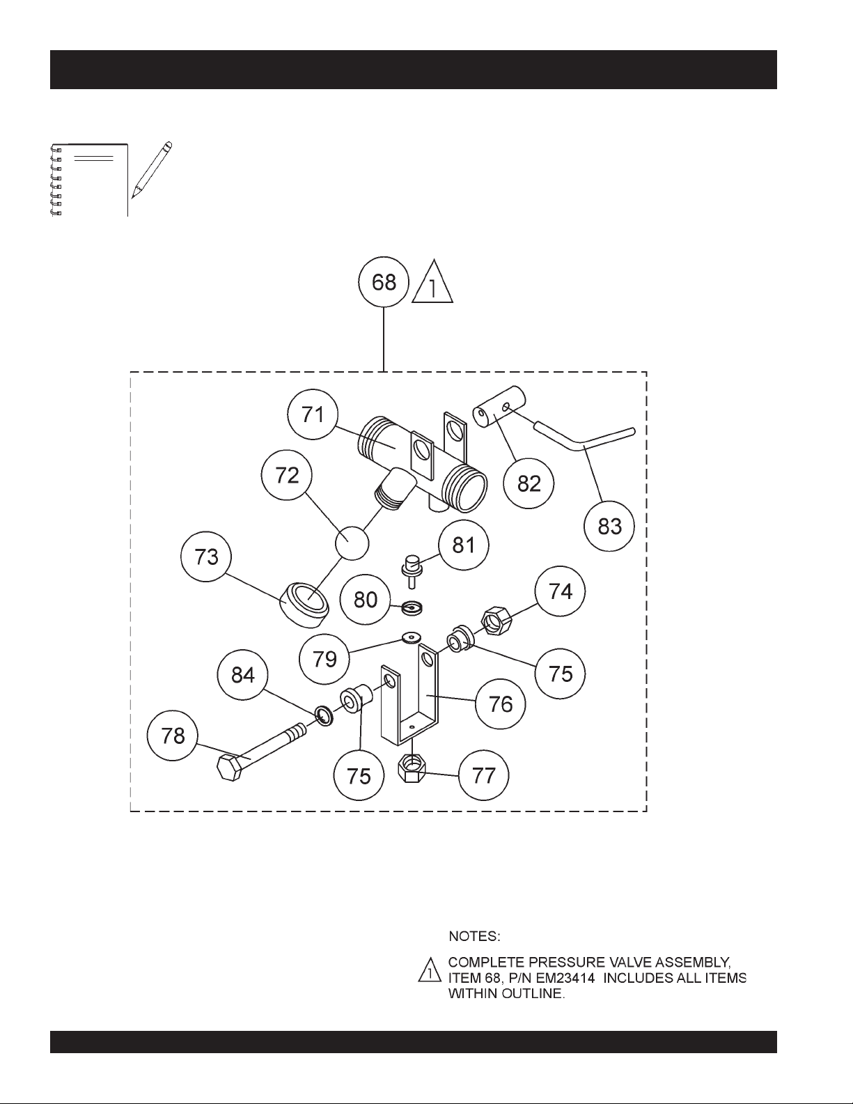
MG-30 PUMP — PRESSURE RELIEF VALVE (3-INCH OUTLET) ASSY.
PRESSURE RELIEF VALVE (3-INCH OUTLET) ASSY.
This assembly drawing is intended to
NOTE
be used with
MG30T-2 Models, using
materials. This application uses a 3.0-
inch (76.2 mm) outlet.
ONLY
the MG30M-2 and
Fireproofing
PAGE 100 — MAYCO MG-30 PUMP — OPERATION AND PARTS MANUAL — REV. #3 (09/15/11)
 Loading...