

Page 1

OPERATION AND PARTS MANUAL
SERIES
MODEL LS300
CONCRETE PUMP
(DEUTZ TD2009L04 DIESEL ENGINE)
Revision #4 (06/21/10)
To find the latest revision of this
publication, visit our website at:
www.multiquip.com
THIS MANUAL MUST ACCOMPANY THE EQUIPMENT AT ALL TIMES.
Page 2

PROPOSITION 65 WARNING
Diesel engine exhaust and some of
PAGE 2 — MAYCO LS300 CONCRETE PUMP • OPERATION AND PARTS MANUAL — REV. #4 (06/21/10)
Page 3

NOTES
MAYCO LS300 CONCRETE PUMP • OPERATION AND PARTS MANUAL — REV. #4 (06/21/10) — PAGE 3
Page 4

TABLE OF CONTENTS
Mayco LS300
Concrete Pump
Proposition 65 Warning .............................................2
Table of Contents ......................................................4
Parts Ordering Procedures ....................................... 5
Safety Message Alert Symbols ............................. 6-7
Rules for Safe Operation .................................... 8-10
Specifications ..........................................................12
Dimensions .............................................................13
Important Hand Signals ..........................................14
General Information .......................................... 15-16
How It Works ...........................................................17
Pump Components ........................................... 18-19
Digital Control Panel Components ..........................20
Digital Readout Screen ...........................................21
Engine Components ...............................................22
Inspection .......................................................... 23-25
Set-Up .....................................................................26
Start-Up Procedure ................................................. 27
Operation .......................................................... 28-31
Pumping Information ......................................... 32-35
Maintenance (Pump) ........................................ 36-43
Maintenance (Trailer) ........................................ 44-46
Trailer Safety Guidelines ................................... 47-61
Troubleshooting (Pump).................................... 62-63
Troubleshooting (Engine) ........................................64
Troubleshooting (Trailer Brake System)..................65
Troubleshooting (Electrical) .............................. 66-68
Wiring Diagram (Control Box) ........................... 69-72
Wiring Diagram (Digital Readout Screen)............... 73
Wiring Diagram (Hopper Vibrator) ..........................74
Hydraulic System Diagram ..................................... 75
Manifold Block Ports ................................................ 76
Appendix–Concrete Mix Information ................. 77-78
Appendix–Slump Test Procedure ............................ 79
Appendix–Recommended Shotcrete System ... 80-81
Appendix–Recommended Shotcrete Accessories ..... 82-83
Explanation of Code in Remarks Column ...............84
Suggested Spare Parts ........................................... 85
Component Drawings
Nameplate and Decals...................................... 86-89
Frame Assembly. .............................................. 90-91
Axle Assembly ................................................... 92-93
Brake Line Assembly ........................................ 94-95
Brake Light Assembly ....................................... 96-97
Trailer Hitch Assembly....................................... 98-99
Battery Assembly .......................................... 100-101
Hopper Assembly .......................................... 102-103
Hopper Attachment Assembly ...................... 104-105
Hopper Interior Assembly ............................. 106-107
Shuttle Cylinder Assembly ............................ 108-109
Lubrication Pistons Assembly ....................... 110-113
Fuel Tank/Water Separator Assembly........... 114-115
Heat Exchanger Assembly ............................ 116-117
Accumulator Assembly.................................. 118-119
Lubrication Panel Assembly .......................... 120-121
Engine Cover Assembly ................................ 122-123
Hydraulic Tank Assembly .............................. 124-125
Engine Assembly .......................................... 126-127
Throttle Assembly ......................................... 128-129
Hydraulic Pump Assembly ............................ 130-131
Manifold Assembly ........................................ 132-133
Control Box Assembly ................................... 134-135
Control Box Harness Assembly .................... 136-137
Terms and Conditions of Sale .............................. 138
Mayco Pump Warranty ......................................... 139
Specification and part number are subject
to change without notice.
PAGE 4 — MAYCO LS300 CONCRETE PUMP • OPERATION AND PARTS MANUAL — REV. #4 (06/21/10)
Page 5

PARTS ORDERING PROCEDURES
Ordering parts has never been easier!
Choose from three easy options:
January 1
Effective:
st
, 2006
Best Deal!
Order via Internet (Dealers Only):
Order parts on-line using Multiquip’s SmartEquip website!
N View Parts Diagrams
N Order Parts
N Print Specification Information
Goto www.multiquip.com and click on
Order Par ts
Order via Fax (Dealers Only):
All customers are welcome to order parts via Fax.
Domestic (US) Customers dial:
1-800-6-PARTS-7 (800-672-7877)
Non-Dealer Customers:
Contact your local Multiquip Dealer for
parts or call 800-427-1244 for help in
locating a dealer near you.
to log in and save!
Order via Phone:
If you have an MQ Account, to obtain a Username
and Password, E-mail us at: parts@multiquip.
com.
To obtain an MQ Account, contact your
District Sales Manager for more information.
Use the internet and qualify for a 5% Discount
on Standard orders for all orders which include
complete part numbers.*
Note: Discounts Are Subject To Change
Fax your order in and qualify for a 2% Discount
on Standard orders for all orders which include
complete part numbers.*
Note: Discounts Are Subject To Change
Domestic (US) Dealers Call:
1-800-427-1244
International Customers should contact
their local Multiquip Representatives for
Parts Ordering information.
When ordering parts, please supply:
R Dealer Account Number
R Dealer Name and Address
R Shipping Address (if different than billing address)
R Return Fax Number
R Applicable Model Number
R Quantity, Part Number and Description of Each Part
NOTICE
All orders are treated as Standard Orders and will
ship the same day if received prior to 3PM PST.
R Specify Preferred Method of Shipment:
UPS/Fed Ex DHL
N Priority One Tr uck
N Ground
N Next Day
N Second/Third Day
www.multiquip.com
WE ACCEPT ALL MAJOR CREDIT CARDS!
MAYCO LS300 CONCRETE PUMP • OPERATION AND PARTS MANUAL — REV. #4 (06/21/10) — PAGE 5
Page 6

SAFETY MESSAGE ALERT SYMBOLS
FOR YOUR SAFETY AND THE SAFETY OF OTHERS!
Safety precautions should be followed at all times when
operating this equipment. Failure to read and understand
the Safety Messages and Operating Instructions could result
in injury to yourself and others.
This Owner's Manual has been developed
to provide complete instructions for the safe
and efficient operation of the Multiquip
Mayco
engine manufacturers instructions for data
relative to its safe operation.
Before using this pump , ensure that the operating
individual has read and understands all instructions in
this manual.
SAFETY MESSAGE ALERT SYMBOLS
The three (3) Safety Messages shown below will inform you
about potential hazards that could injure you or others. The
Safety Messages specifically address the level of exposure
to the operator, and are preceded by one of three words:
DANGER, WARNING, or CAUTION.
DANGER
You WILL be KILLED or SERIOUSLY injured if you
do not follow directions.
LS300 Concrete
pump. Refer to the
HAZARD SYMBOLS
Potential hazards associated with operation of the pump will
be referenced with Hazard Symbols which appear throughout
this manual, and will be referenced in conjunction with Safety
Message Alert Symbols. Some examples are listed below:
WARNING - LETHAL EXHAUST GASES
confined area or enclosed structure that does not provide
ample free flow air.
WARNING - EXPLOSIVE FUEL
DO NOT overfill tank, since spilled fuel could ignite if it
comes into contact with hot engine parts or sparks from
the ignition system. Store fuel in approved containers,
in well-ventilated areas and away from sparks and
flames. NEVER use fuel as a cleaning agent.
Diesel engine exhaust gases contain poisonous
carbon monoxide. This gas is colorless and
odorless, and can cause death if inhaled.
NEVER operate this equipment in a
Diesel fuel
its vapors can cause an explosion if ignited.
DO NOT start the engine near spilled fuel
or combustible fluids. DO NOT fill the fuel
tank while the engine is running or hot.
is extremely flammable, and
WARNING - BURN HAZARDS
WARNING
You COULD be KILLED or SERIOUSLY injured if
you do not follow directions.
operate the engine with heat shields or heat guards
CAUTION
You CAN be injured if you do not follow directions
PAGE 6 — MAYCO LS300 CONCRETE PUMP • OPERATION AND PARTS MANUAL — REV. #4 (06/21/10)
removed.
Engine components can generate extreme
heat. To prevent burns, DO NOT touch
these areas while the engine is running or
immediately after operations. NEVER
Page 7
SAFETY MESSAGE ALERT SYMBOLS
WARNING - ROTATING PARTS
NEVER operate equipment with covers, or
guards removed. Keep
hair
and clothing away from all moving parts
to prevent injury.
CAUTION - ACCIDENTAL STARTING
ALWAYS place the Engine ON/OFF switch
in the OFF position. NEVER perform
maintenance on the unit with the ignition
key in the ON position.
CAUTION - OVER-SPEED CONDITIONS
NEVER tamper with the factory settings of
the engine governor or settings. Personal
injury and damage to the engine or
equipment can result if operating in speed
ranges above maximum allowable.
fingers, hands
CAUTION - RESPIRATORY HAZARDS
,
CAUTION - SIGHT AND HEARING HAZARDS
CAUTION - EQUIPMENT DAMAGE MESSAGES
Other important messages are provided throughout
this manual to help prevent damage to your concrete
pump, other property, or the surrounding environment.
ALWAYS wear approved
protection.
This machine is capable of producing noise
levels above 85 dB.
Hearing protection is required.
Always wear eye protection.
respiratory
This
pump
, other property, or the
surrounding environment could be damaged
if you do not follow instructions.
MAYCO LS300 CONCRETE PUMP • OPERATION AND PARTS MANUAL — REV. #4 (06/21/10) — PAGE 7
Page 8
■
DANGER - READ OPERATION AND PARTS
Failure to follow instructions in this manual may lead to
death!
serious injury or even
operated by trained and qualified personnel only! This
equipment is for industrial use only.
The following safety guidelines should always be used when
operating the LS300 concrete pump:
GENERAL SAFETY
■
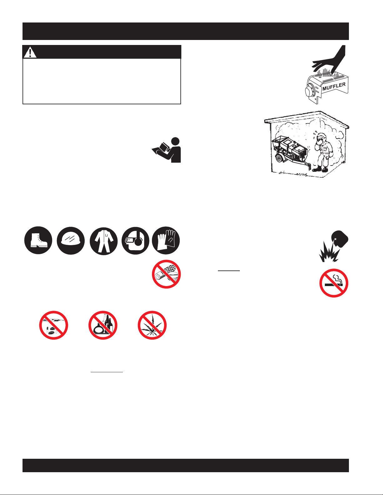
DO NOT operate or service this equipment
before reading this entire manual.
■
This equipment should not be operated by persons under
18 years of age.
■
NEVER operate this equipment without proper protective
clothing, shatterproof glasses, steel-toed boots and other
protective devices required by the job.
This equipment is to be
NEVER touch the hot exhaust manifold, muffler
or cylinder. Allow these parts to cool before
servicing engine or pump.
■
High Temperatures – Allow the engine
to cool before adding fuel or performing
service and maintenance functions.
Contact with
cause serious burns.
■
The engine section of this
pump requires an
adequate free flow of
cooling air.
operate the pump in any
enclosed or narrow area
where free flow of the air
is restricted. If the air flow is restricted it will cause serious
damage to the pump or engine and may cause injury to
people. Remember the pump's engine gives off
carbon monoxide gas.
■
ALWAYS refuel in a well-ventilated area, away from
sparks and open flames.
RULES FOR SAFE OPERATION
hot!
components can
NEVER
DEADLY
■
■
NEVER operate this equipment when not
feeling well due to fatigue, illness or taking
medicine.
■
NEVER operate this equipment under the
influence or drugs or alcohol.
■
ALWAYS check the machine for loosened threads or bolts
before starting.
■
ALWAYS wear proper respiratory (mask),
eye
protection equipment when operating the pump.
■
Whenever necessary, replace nameplate, operation and
safety decals when they become difficult read.
■
Manufacture does not assume responsibility for any
accident due to equipment modifications.
■
NEVER use accessories or attachments, which are not
recommended by Multiquip for this equipment. Damage
to the equipment and/or injury to user may result.
hearing
and
■
■
■
■
■
■
■
ALWAYS use extreme caution when working
with flammable liquids. When refueling, stop
the engine and allow it to cool.
NEVER
Fire or explosion could result from
vapors
NEVER operate the pump in an explosive
atmosphere or near combustible materials.
An explosion or fire could result causing severe
smoke
, or if fuel is spilled on a
around or near the machine.
hot!
fuel
engine.
bodily
harm or even death.
Topping-off to filler port is dangerous, as it tends to spill
fuel.
ALWAYS remove the
unattended.
ALWAYS block the
slope.
ALWAYS maintain this equipment in a safe operating
condition at all times.
ALWAYS stop the engine before servicing, adding fuel or
oil.
ignition key
wheels
on the unit when using on a
when leaving the pump
PAGE 8 — MAYCO LS300 CONCRETE PUMP • OPERATION AND PARTS MANUAL — REV. #4 (06/21/10)
Page 9

■
NEVER run engine without air filter. Severe engine
damage may occur.
■
ALWAYS be sure the operator is familiar with proper safety
precautions and operation techniques before using pump.
■
ALWAYS store equipment properly when it is not being
used. Equipment should be stored in a clean, dry location
out of the reach of children.
■
DO NOT operate this equipment unless the hopper grate,
guards and safety devices are attached and in place.
■
CAUTION must be exercised while servicing this
equipment. Rotating and moving parts can cause injury
if contacted.
■
Keep all
from the equipment at all times.
■
Before start-up, check the hopper and remove all foreign
matter and debris.
■
DO NOT use worn or damaged hose couplings, inspect
all hoses and couplings for wear. Replace any worn or
defective hose or couplings immediately.
■
Keep hands out of the hopper when the engine is running.
■
DO NOT disconnect hose couplings or nozzle while under
pressure. Relieve pressure by activating the reverse
function switch located on the control panel.
■
Unauthorized equipment modifications will void all
warranties.
inexperienced
and
unauthorized
people away
TRANSPORTING
■
■
■
Towing
■
■
■
■
■
■
■
■
■
RULES FOR SAFE OPERATION
ALWAYS shutdown engine before transporting the pump.
Tighten fuel tank cap securely to prevent fuel from
spilling.
Drain fuel when transporting pump over long distances
or bad roads.
Before towing, check the hitch and secure the safety
chain to the towing vehicle.
When towing, an adequate safety chain must be fastened
to the frame, refer to Towing Guidelines.
Tow only with a vehicle and hitch rated to pull a 6,000
lbs. load.
If unit is equipped with ball hitch coupler, use only 2" all
steel ball rated for minimum of 6,000 lbs. Use 1" hardened
steel pull pin, if not equipped with ball hitch.
This equipment shall not be towed or operated by
individuals who cannot read understand the signs, decals
or operating instructions.
When towing at night,
DO NOT tow unit with hopper full of material.
DO NOT tow unit with hoses attached.
DO NOT tow unit in excess of 55 MPH on highways.
always
have rear tail lights ON.
■
Check all fasteners periodically for tightness. Also check
towing tongue bolt, lock nut and wheel lug nuts for wear.
■
Test the
test is to shut down the engine.
■
Refer to the
technical questions or information recommended by
Multiquip for this equipment. Damage to the equipment
and or injury to user may result.
■
Always use properly rated hoses and clamps — 1500
PSI and higher.
pump's ON/OFF
DEUTZ Engine Owner's Manual
MAYCO LS300 CONCRETE PUMP • OPERATION AND PARTS MANUAL — REV. #4 (06/21/10) — PAGE 9
switch. The purpose of this
for engine
MAINTENANCE SAFETY
■
■
■
■
■
■
NEVER lubricate components or attempt service on a
running pump .
ALWAYS allow the pump a proper amount of time to
cool before servicing.
Keep the pump in proper running condition.
Fix damage to the pump immediately and always replace
broken parts.
Dispose of hazardous waste properly. Examples of
potentially hazardous waste are used motor oil, fuel and
fuel filters.
DO NOT use plastic containers to dispose of hazardous
waste.
Page 10
RULES FOR SAFE OPERATION
BATTERY
The battery contains acids that can cause injury to the eyes
and skin. To avoid eye irritation,
Use well insulated gloves when picking up the battery. Use
the following guidelines when handling the battery:
■■
■
DO NOT drop the battery. There
■■
is the possibility of risk that the
battery may explode.
■■
■
DO NOT expose the battery to
■■
open flames, sparks, cigarettes
etc. The battery contains combustible gases and liquids.
If these gases and liquids come in contact with a flame
or spark, an explosion could occur.
■■
■
ALWAYS keep the battery charged. If the battery is not
■■
charged a buildup of combustible gas will occur.
always
wear safety glasses.
EMERGENCIES
■
ALWAYS know the location of the
nearest
■
ALWAYS know the location of the
nearest and
■
In emergencies
nearest phone or
Also know the phone numbers of the nearest
ambulance, doctor
information will be invaluable in the case of an
emergency.
fire extinguisher
first aid kit
always
.
.
know the location of the
keep a phone on the job site
and
fire department
.
. This
■■
■
ALWAYS keep battery charging and cables in good
■■
working condition. Repair or replace all worn cables.
■■
■
ALWAYS recharge the battery in an vented air
■■
environment, to avoid risk of a dangerous concentration
of combustible gases.
■■
■
In case the battery liquid (dilute sulfuric acid) comes in
■■
contact with
immediately with plenty of water.
■■
■
In case the battery liquid (dilute sulfuric acid) comes in
■■
contact with your eyes, rinse eyes immediately with
plenty of water, then contact the nearest doctor or hospital,
and seek medical attention.
clothing or skin
, rinse skin or clothing
PAGE 10 — MAYCO LS300 CONCRETE PUMP • OPERATION AND PARTS MANUAL — REV. #4 (06/21/10)
Page 11

NOTES
MAYCO LS300 CONCRETE PUMP • OPERATION AND PARTS MANUAL — REV. #4 (06/21/10) — PAGE 11
Page 12

ledoM003SL
etaRgnipmuP*ruohrep.sdy.uc03otpU
dohteMgnipmuPnotsiPgnitacorpiceR
SPECIFICATIONS
SNOITACIFICEPSPMUP.1ELBAT
eziSetagerggAmumixaM )mm83(suni
thgieHgnipmuPlacitreV )m9.06(.tf002fossecxEotpU
erusserPecaFnotsiP)rab61.55(ISP008
uPlatnoziroH*)m342(.tf008
eziSeriT51R57/522TS
snoitpO rotarbiVneercSre
muloV*
ecnatsiDgnipm
yticapaCxoBnoitacirbuLrednilyC )sretiL6.7(snollaG2
yticapaCdiulFciluardyH )sreti
yticapaCknaTleuF)sretiL16(snollaG61
yticapaCreppoH.tf.uc01
esoHlairetaM
ledoMenignE
)sdiulfhtiw(thgieW)gk107,1(.sbl057,3
m.ni2/1-1
L521(snollaG33
.aid.ni5,.ni4,.ni3
m721,mm6.101,mm2.67(
)m
obruTztueD
40L9002DTleseiD
ppoH,lortnoCetomeRsseleriW
snotitidnocetisbojdnadesuezisenil,pmuls,ngisedximnognidnepedyravlliwtuptuoe
.2ELBATSNOITACIFICEPSENIGNE
ledoM
epyT
srednilyCfo.oN
ekortSxeroB
3xni5.3
4
tuptuOdetaR
tnemecalpsiD
gnitratS
yticapaCliOebuL
epyTleuF
yrettaB
40L9002DTztueD
enignEleseiD
leseiDdelooc-riA,ekorts4
)mm09xmm09(.ni5.
mpr0082@PH76
)L92.2(.ni.uc041
CDV21cirtcelE
)L5.7(lag6.1
leuFleseiD2#
71puorGVCDV21
PAGE 12 — MAYCO LS300 CONCRETE PUMP • OPERATION AND PARTS MANUAL — REV. #4 (06/21/10)
Page 13
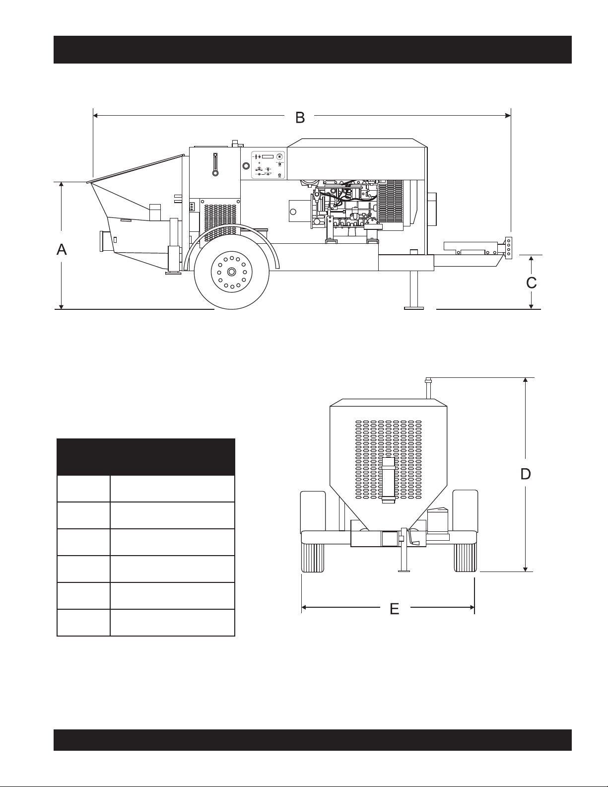
DIMENSIONS
SNOISNEMID.3ELBAT
.FERSNOISNEMID
A).mc2.901(.ni34
B).mc104(.ni851
C).mc9.64(.ni5.81
D).mc6.761(.ni66
E).mc1.561(.
MAYCO LS300 CONCRETE PUMP • OPERATION AND PARTS MANUAL — REV. #4 (06/21/10) — PAGE 13
ni56
Figure 1. Dimensions
Page 14

IMPORTANT HAND SIGNALS
Figure 2 displays the basic hand signals commonly used in concrete pumping operations.
Figure 2. Operation Hand Signals
PAGE 14 — MAYCO LS300 CONCRETE PUMP • OPERATION AND PARTS MANUAL — REV. #4 (06/21/10)
Page 15

GENERAL INFORMATION
CONCRETE MIX DESIGN
Mix design is most important to achieve maximum pumpability.
Pumpability is affected by, among other factors, the type and
gradation of aggregate used. Natural aggregates make a more
workable mix and pump more readily than crushed aggregates.
A blend of natural and crushed aggregates will produce a
workable mix. The type and gradation of aggregates is equally
important for workability as the size and percentage of coarse
aggregates in the mix.
The term “aggregates” describes all of the solid materials, from
the largest rock to the smallest grain of sand, contained in the
concrete mix.
Concrete mixes with a consistency as dry as one-inch slump
and as wet as ten-inch slump have been pumped; but for
maximum efficiency from the pump, a slump ranging from two to
six inches will produce a more workable mix than one that
contains more or less water.
The principle of concrete pumping is based on self-lubrication.
As it moves through the transfer line, the concrete takes the
shape of a plastic cylinder. It is forced through the transfer line on
a film of mortar that is self-troweled to the service of the transfer
line around its full periphery by the slug of concrete itself.
A slump rating should be used with discretion; it is not always a
real indication of the pumpability of the mix. The concrete may
be workable in the sense that it will readily flow into place, but
the same mix may not respond to pressure. Overly wet mixes
tend to separate. In addition to affecting the strength and quality
of the concrete, the delivery system will not tolerate separation.
Overly dry mixes are similarly unsatisfactory if they lack plasticity
and tend to be crumbly. To be properly pumped, the mix must be
able to continuously coat the inside of the line with a lubricating
seal of mortar.
There are four ways in which this seal can be lost:
1. By pumping excessively wet mixes which do not have
enough cohesion to hold together.
2. By pumping harsh undersanded concrete with poorly graded
aggregates which can jam together when the pressure
becomes too great for the insufficient amount of sand to
hold the aggregates apart.
3. By getting a rock pocket, such as mixer tailings, into the
pump valve. This rock pocket will have an insufficient coating
of mortar and the mix will not be plastic enough to allow the
valve to operate or the mix to move in the line.
4. Through excessive bleeding. If the mix is short or fines, but
the sand is otherwise fairly well graded, bleeding will not
normally create any problems as long as the pump continues
operation. But, if the pump is shut down, bleeding can result
in a loss of lubrication and blocked erratic flow.
The above are bad concrete practices, regardless of how the
mix is to be placed. But, these points do show that special mixes
are not always needed, within limits, for pumping concrete. Good
aggregate gradation is most important to pump concrete the
maximum distance.
The use of admixtures can have a beneficial effect on pumpability.
Most of the dispersing agents will fatten, retard bleeding, and
increase workability. Thus, the average concrete can be pumped
for appreciably longer distances. Air entraining agents will also
improve workability, although they cannot be used as a substitute
for good gradation of the aggregate. Pumping will not appreciably
affect the final air content of the mix. High-early cement tends to
give a more readily pumpable mix with superior water retaining
qualities. However, if delays are likely to occur, extra care must
be exercised due to the faster setting time over regular cement.
The Mayco LS300 models will pump a wide variety of concrete
pump mixes. But, there are guidelines that must be followed.
Use this information in conjunction with the
of this manual.
Operation
section
MAYCO LS300 CONCRETE PUMP • OPERATION AND PARTS MANUAL — REV. #4 (06/21/10) — PAGE 15
Page 16

GENERAL INFORMATION
REGIONAL DIFFERENCES
Concrete is made by mixing locally available rock and sand with
cement and water. For this reason there are great differences in
the pumpability of concrete from one region of the country to
another.
It is impossible to define a specific mix for each region that the
concrete pump be will working in. Therefore, the mixes listed in
Appendix - Concrete Mix Information will provide a basic
guideline for establishing the proper mix design for your area.
Use this information to specify your requirements to your local
ready-mix batch plant, contractor and civil engineer. It may take
minor adjustments to make a mix pumpable, so you should
explain your needs.
The elements that have to be controlled and consistently
maintained by the batch plant are:
1. The sizing and mix percentage of rocks, gap graded from
the largest down through the smallest sizes.
2. Sand with a sieve analysis that has the proper percentage
of fines, ASTM C33 spec.
3. Sufficient cement to produce the required design strength
of the concrete and provide the lubricating binder to pump
the concrete through the delivery system.
5. The proper amount of water to make a workable slump and
plasticize the mix.
In addition, this Mayco Concrete Pump can be used to pump a
large aggregate hard rock as follows:
1. Pea rock (1/2" minus) pump with mixes being as low as 30%
rock and 70% sand.
2. Shortening pea rock when used with an air compressor and
nozzle. (See back pages for recommended setup.)
3. “Mud Jacking”, high pressure grouting.
Use a minimum of:
500 lbs. of cement/cu yd for 2500 p.s.i. concrete after 28
days.
530 lbs. of cement/cu yd for 3000 p.s.i. concrete after 28
days.
600 lbs. of cement/cu yd for 4000 p.s.i. concrete after 28
days.
4. Admixture pump-aid if necessary.
PAGE 16 — MAYCO LS300 CONCRETE PUMP • OPERATION AND PARTS MANUAL — REV. #4 (06/21/10)
Page 17

The following is a brief explanation of how the concrete cylinders,
hydraulic cylinders, shuttle tube, valves and hopper work in
sequence to pump concrete.
The hydraulic pressure is generated by a variable volume,
pressure compensated, axial piston pump that is driven by a
diesel engine. The rod sides of the drive cylinders are
hydraulically connected together creating a “slave circuit,” which
allows hydraulic oil to transfer from one piston to the other.
The two part cycling sequence is initiated by an electrical signal
generated by two proximity switches activated by the drive
cylinder. The proximity switches are normally open, magnetically
sensing the movement of the main drive cylinder. As the drive
cylinder piston head passes the proximity switch, an electrical
signal is sent to the solenoid operated pilot valve which in turn
directs pilot oil to the four valves controlling the drive cylinder
and the shuttle cylinder.
HOW IT WORKS
TO TANK
HYDRAULIC
CYLINDERS
HIGH PRESSURE
OIL FROM PUMP
PROXIMITY
SWITCH
SLAVE
OIL
CONCRETE
A
B
SHUTTLE TUBE MOTION
CYLINDERS
PISTON
CUP
SHUTTLE TUBE
Figure 3. Pumping Cycle 1
Figure 4. Pumping Cycle 2
In the first cycle, hydraulic pressure is applied to cylinder (B),
causing the hydraulic piston, which is connected to the concrete
piston and piston cup, to discharge concrete into the delivery
line (Figure 3).
As one cylinder is discharging concrete, the hydraulic oil from
the rod side (B) of the drive cylinders is being transferred through
the slave circuit causing the opposite cylinder (A) to move back
on the suction stroke, filling the cylinder with concrete.
The shuttle tube is sequenced to pivot to each concrete cylinder
as the drive cylinders stroke to push concrete. As the second
cycling sequence begins (Figure 4), the shuttle tube pivots to
the opposite cylinder (A). The hydraulic piston passes under the
proximity switch and sends pressure to the piston, causing it to
stroke and discharge concrete into the delivery line. Hydraulic
oil is transferred through the slave circuit to cylinder B, causing it
to start a suction stroke, refilling it with concrete. The pumping
sequence then repeats for the duration of the operation.
MAYCO LS300 CONCRETE PUMP • OPERATION AND PARTS MANUAL — REV. #4 (06/21/10) — PAGE 17
Page 18
PUMP COMPONENTS
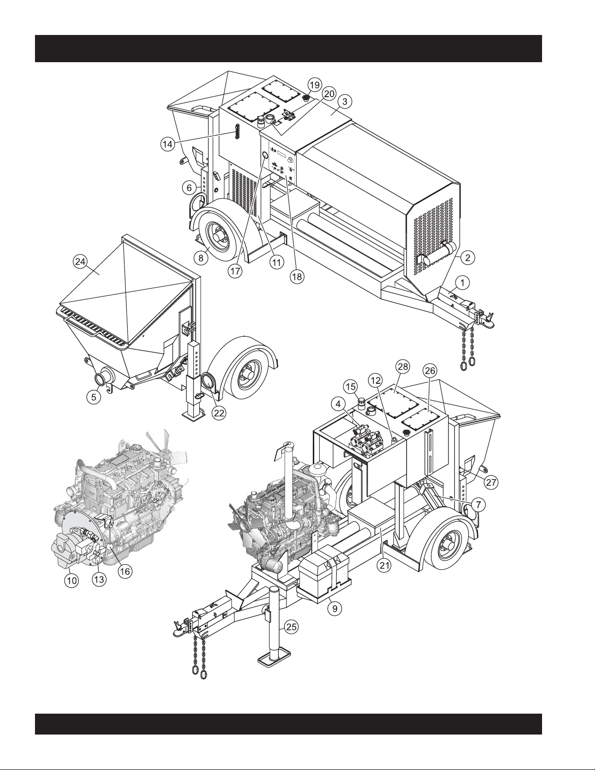
Figure 5. Major Pump Components
PAGE 18 — MAYCO LS300 CONCRETE PUMP • OPERATION AND PARTS MANUAL — REV. #4 (06/21/10)
Page 19

PUMP COMPONENTS
Figure 5 illustrates the location of the major components for
the LS300 Concrete Pump. The function of each component
is described below:
1. Tow Hitch Coupler – Requires a 2-inch ball hitch or a
3-inch pintle. Capable of towing 6,000 lbs.
2. Documentation Box – Contains engine and pump
operation, parts and maintenance information.
3. Manifold Access Door– Release latch and lift door to
access the Hydraulic Manifold Block.
4. Hydraulic Manifold Block – Manifold block that
controls the flow of hydraulic pressure to the
components required to control the pump.
5. Hopper Discharge Sleeve – Connect hoses or steel
pipes to the discharge sleeve for pouring concrete.
6. Pump End Jack Stand – Use this jack stand to support
the rear end of the pump. NEVER deploy on un-level
ground and always check for firmness of ground.
7. Shuttle Cylinder – Under pressure, the shuttle cylinder
shears concrete passing from the concrete cylinder to
the delivery line during the cycle phase.
8. Tires — This trailer uses two ST205-750 x15E type
tires. Tire inflation pressure is the most important factor
in tire life. Pressure should be checked to
before operation. DO NOT bleed air from tires when
they are hot. Check inflation pressure weekly during
use to insure the maximum tire life and tread wear.
9. Battery – This unit uses a +12 VDC type battery.
ALWAYS use gloves and eye protection when handling
the battery.
10. Hydraulic Pump – This unit incorporates an axial
variable displacement hydraulic piston pump.
11. Heat Exchanger – Reduces temperature of the
hydraulic oil. The exchanger draws oil from the hydraulic
system into the heat exchanger before allowing it to
flow back into the reservoir.
12. Accumulator – Stores oil under pressure and releases
it to the pilot valves to ensure enough pressure is
provided to operate valve.
13. Stroke Volume Control Dial – Turns CW/CCW to
increase or decrease the number of strokes per minute
of the pump.
50 psi cold
14. Hydraulic Oil Sight Glass – Use to determine the
amount of hydraulic oil remaining in tank. The sight
glass also contains a temperature gauge for monitoring
the temperature of the hydraulic oil.
15. Hydraulic Oil Tank/Cap– Remove cap to add hydraulic
fluid. Fill with Shell Oil Tellus 68 or Mobil Oil DFE26 if
level is low.
16. Engine Throttle Lever – Controls the speed of the
engine. For load conditions (pumping water) ALWAYS
run the engine at
17. Pumping Pressure Gauge – Used to monitor pressure
in the concrete cylinders and shuttle tube.
18. Control Box – Contains the electrical components
required to run the pump. See Control Box Components
section for component callouts.
19. Fuel Tank/Cap – Fill with diesel fuel. Fuel tank (cell)
holds approximately 16 gallons (61 liters). DO NOT top
off fuel. Wipe up any spilled fuel immediately.
20. Hydraulic Oil Filter – This in-tank return hydraulic
filter with a 10 micron cleanable filter is designed to
remove all particles large enough to cause wear and
job break down. Under normal conditions, clean every
6 months.
21 Lubrication Box – This box is empty when shipped
from the factory. Please fill with 3 gallons (11.35 liters)
of SAE 30 motor oil for first time use. Also check the
dual clean-out point on bottom of lubrication box for a
secure tight fit.
22. Rear Running Lights – ALWAYS check and make
sure both the right and left running lights are functioning
correctly before towing the pump.
24. Hopper/Hood – Lift hood to fill. Concrete from a RediMix truck is poured into this hopper. The hopper can
hold 10 cu. ft of concrete. NEVER put hands or any
other parts of you body into the hopper.
25. Tow End Jack Stand – Use this jack stand to level
and support the tow end of the pump.
26. Fuel Reservoir – Holds 16 gallons (61 liters) of diesel
fuel.
27. Fuel Gauge – Indicates the amount of fuel in the fuel
reservoir.
full speed.
28. Hydraulic Oil Reservoir – Holds 33 gallons (125 liters)
of hydraulic oil.
MAYCO LS300 CONCRETE PUMP • OPERATION AND PARTS MANUAL — REV. #4 (06/21/10) — PAGE 19
Page 20

DIGITAL CONTROL PANEL COMPONENTS
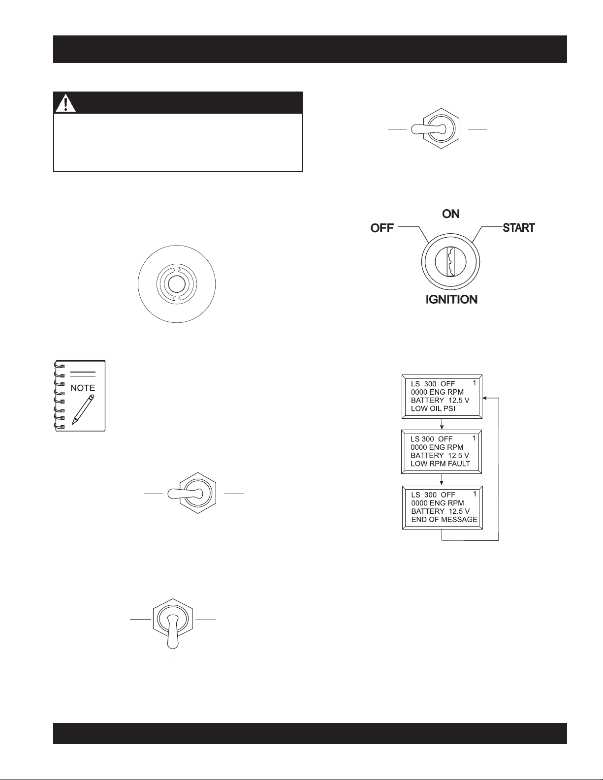
Figure 6. Pump Digital Control Panel Components
1. Emergency Stop Button – Press emergency stop
button to stop pump in an emergency. Turn knob
counterclockwise to disengage the stop button.
2. Ignition Switch – Insert the ignition key here to start
the engine. Turn the key clockwise to the ON position,
then continue turning clockwise to the START position
and release. To stop the engine turn the key fully
counterclockwise to the STOP position.
3. Digital Readout Screen – Displays and monitors the
various functions of the machine.
4. Scroll Switch – Allows the operator to scroll the various
readout screens.
5. Reset Switch – Allows the operator to reset the stroke
counter.
6. Remote Cable Connector – Insert the remote control
input cable into this connector.
7. Direction Control Switch – This 2-position switch
controls the direction of flow for any mix in the pump.
The
leftmost
forward and the
direction to reverse.
position sets the pumping direction to
rightmost
position sets the pumping
8. Pumping Control Switch – This 3-position switch
9. Cylinder Stroke Control Switch – This 2-position
10. Manual Cylinder Jogging Switch – This 2-position
controls the pumping of the pump. The
position (REMOTE) is for use with the remote control
unit, the
pumping operation, and the
(CENTER OFF) prevents pumping.
switch controls the pumping function. The
position (AUTOMATIC) sets the pump to
cycling
operation.
The
automatic to
to be manually cycled using the
Jogging Switch
switch allows the operator to manually jog the cylinders
to assist in clearing material line packs and is used to
test pumping pressure (See
section of this manual for testing procedure).
The
rightmost
leftmost
position (LOCAL) is for normal
centermost
. Set the switch to this position for normal pump
rightmost
position (JOG) changes the pump from
manual cycling
. This allows the cylinders
Manual Cylinder
.
Initial Start-up Procedure
leftmost
position jogs Cylinder “A” and the
position jogs Cylinder “B”.
rightmost
position
leftmost
automatic
13. Main Pressure Gauge – This gauge monitors the
system pressure while pumping material. The maximum
pressure rating is 3100 PSI ± 50.
PAGE 20 — MAYCO LS300 CONCRETE PUMP • OPERATION AND PARTS MANUAL — REV. #4 (06/21/10)
Page 21
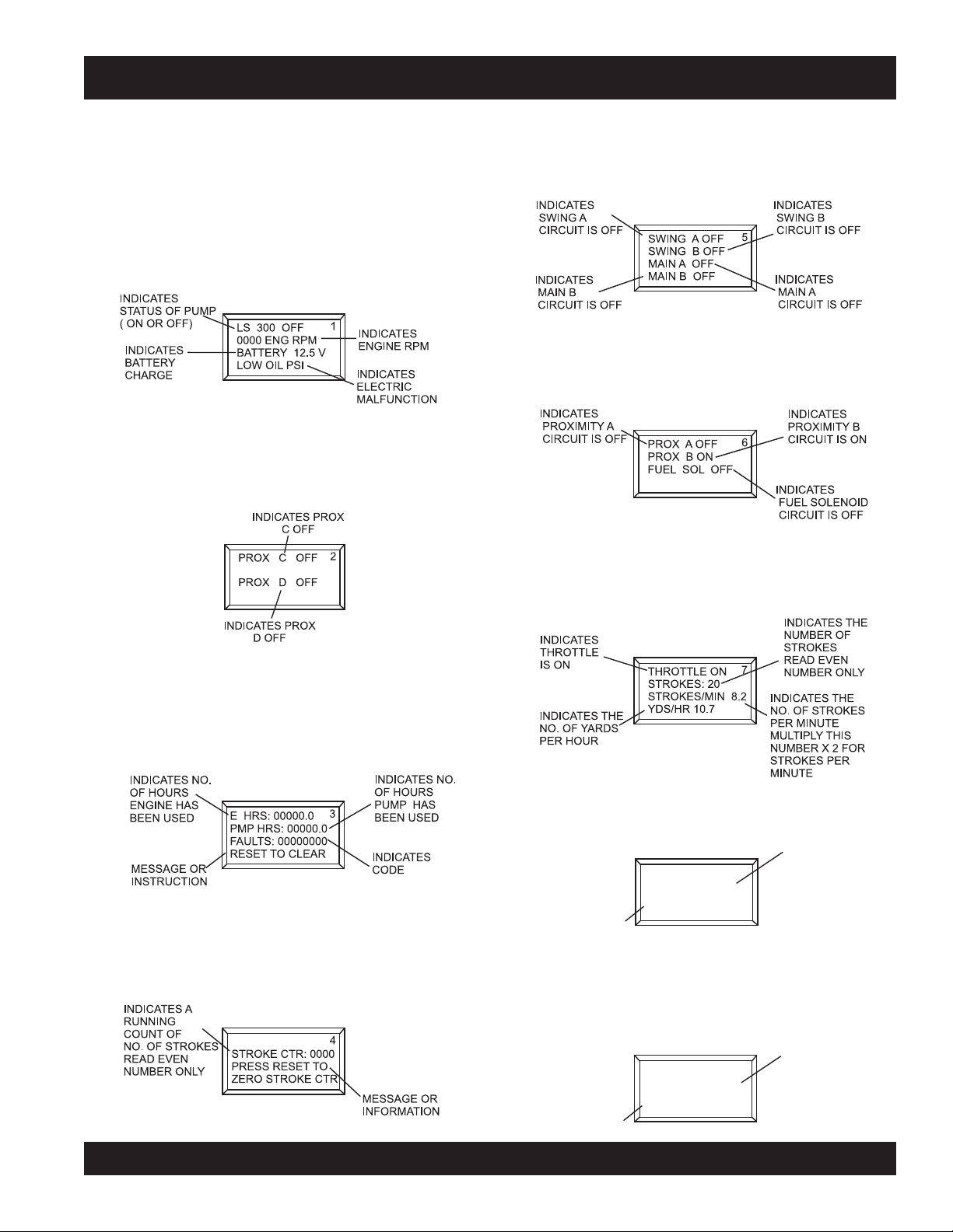
DIGITAL READOUT SCREEN
INSTRUCTION
OR MESSAGE
INDICATES THE
FUEL SOLENOID
IS OFF
TO TEST FUEL
SOL PRESS RESET
FUEL SOL OFF
8
PRIMARY SCREEN
Screen 5
Displays the ON/OFF electrical signal status of the various
Screen 1
Indicates the various modes of the switch settings.
12 volt solenoids (Swing A circuit, Main A circuit, Main B
circuit).
Monitors engine RPM - Idle speed 900, High speed 2550.
Battery charge indicator - Normal charge 13+ volts.
Indicates electrical malfunction - Refer to Troubleshooting
section.
Screen 6
Displays the ON/OFF electrical signal status for the
Proximity Switch A, Proximity Switch B, Engine Fuel
Solenoid, and Unloader Solenoid.
SECONDARY SCREENS
Screen 2
Displays the status of the shuttle cylinder proximity switches.
Screen 7
Displays the number of times the main hydraulic cylinders
stroke and the yards per hour output. This indicator can be
reset to zero by the RESET switch on the control panel.
Screen 3
Displays the number of hours the engine and pump have
been used and the fault codes the pump has registered. All
three indicators can be reset to zero by the RESET switch
on the control panel.
Screen 8
Displays the electrical status of the engine fuel solenoid. To
test the 12-Volt solenoid status, activate with the RESET
switch on the control panel.
Screen 4
Displays the number of strokes the main hydraulic cylinders
have gone through. This indicator can be reset to zero by
the RESET switch on the control panel.
Screen 9
Displays the communication status of the (optional) radio
remote control. To activate a new remote control connection,
use the reset switch on the control panel.
MAYCO LS300 CONCRETE PUMP • OPERATION AND PARTS MANUAL — REV. #4 (06/21/10) — PAGE 21
IINSTRUCTION
OR MESSAGE
RADIO ADDRESS
COMMUNICATING
PRESS RESET TO
LEARN A NEW ONE
9
INDICATES
THAT RADIO
REMOTE IS ON
Page 22

ENGINE COMPONENTS
Figure 7. Deutz TD2009L04 Diesel Engine Components
INITIAL SERVICING
The engine (Figure 7) must be checked for proper lubrication
and filled with fuel prior to operation. Refer to the
manufacturer's engine manual for instructions and details
of operation and servicing.
1. Fuel Filter – Service the fuel filter as recommended in
the maintenance section of this manual.
2. Oil Filter – Prevents dirt and other debris from entering
the engine. Service the oil filter as recommended in
the maintenance section of this manual.
3. Crankcase Drain Plug – Remove this plug to drain
engine oil from the engine crankcase. For best results
drain engine oil when oil is warm.
4. Dip Stick – Remove dipstick to determine if the engine
oil level is low. If low add oil as specified in Table 4.
5. Engine Throttle Lever – Controls the speed of the
engine. For load conditions (pumping water) ALWAYS
run the engine at
6. V-Belt Cover – Remove this cover to gain access to
the V-belt. When replacing V-belt, use only recommended
type V-belt.
full speed.
7. Alternator – Provides power to the electrical system.
Replace with only manufacturers recommended
replacement parts.
8. Air Filter – Prevents dirt and other debris from entering
the fuel system. Release the latches on the side of the
air filter cover to gain access to filter element.
9. Muffler – Used to reduce noise and emissions. NEVER
touch the muffler while it is hot! Serious burns can result.
NEVER operate the engine with the muffler removed.
10. Oil Filler Port/Cap – Remove this cap to add engine
oil to the crankcase. Fill with recommended type of oil
as specified in the maintenance section of this manual.
11. Starter/Solenoid – This engine uses a 12 VDC , 2.7kW
(3.7 HP) starter motor with solenoid.
Operating the engine without an air filter, with
a damaged air filter, or a filter in need of
replacement will allow dirt to enter the engine,
causing rapid engine wear.
PAGE 22 — MAYCO LS300 CONCRETE PUMP • OPERATION AND PARTS MANUAL — REV. #4 (06/21/10)
Page 23

INSPECTION
CAUTION - GENERAL SAFETY GUIDELINES
NEVER operate the pump in a confined
area or enclosed area structure that
does not provide ample
air
.
ALWAYS wear approved
hearing
the pump .
NEVER operate the pumps's engine
with the engine hood removed. The
possibility exists of
and
clothing
the V-belt, causing injury and bodily
harm.
NEVER place hands or feet inside the
ALWAYS make while the engine is running. ALWAYS
shut down the engine before performing any kind of
maintenance service on the pump.
becoming entangled with
free flow of
protection before operating
hands, long hair
,
hopper
eye
and
.
FUEL CHECK
1. Check the fuel gauge built into the fuel tank cap
(Figure 8) to determine if the pump's engine fuel is low.
Refuel as needed.
WARNING - EXPLOSIVE FUEL
Diesel fuel
its vapors can cause an explosion if
ignited. DO NOT start the engine near
spilled fuel or combustible fluids. DO
NOT fill the fuel tank while the engine
is running or hot.
DO NOT overfill tank, since spilled fuel could ignite if it
comes into contact with hot engine parts or sparks from
the ignition system. Store fuel in approved containers,
in well-ventilated areas and away from sparks and
flames. NEVER use fuel as a cleaning agent.
is extremely flammable, and
See Figures 5, 6, and 7 for the location of
any control or component referenced in this
section.
BEFORE STARTING
1. Read safety instructions at the beginning of manual.
2. Clean the
larly the engine cooling air inlet, and heat exchanger.
3. Check the
replace air filter with a new one as required.
4. Check fastening nuts and bolts for tightness.
WARNING - EXPLOSIVE FUEL
Handle fuel safely. Diesel fuel is highly
can be dangerous if
refueling. DO NOT attempt to refuel pump if the engine
is hot or running. ALWAYS allow engine to
refueling.
entire pump
air filter
, removing dirt and dust, particu-
for dirt and dust. If air filter is dirty,
mishandled. DO NOT
flammable
smoke
cool
before
and
while
Figure 8. Fuel Cap Gauge
2. If fuel is low, remove fuel filler cap and fill with
diesel fuel
(Figure 9).
Figure 9. Adding Diesel Fuel
#2
MAYCO LS300 CONCRETE PUMP • OPERATION AND PARTS MANUAL — REV. #4 (06/21/10) — PAGE 23
Page 24
INSPECTION
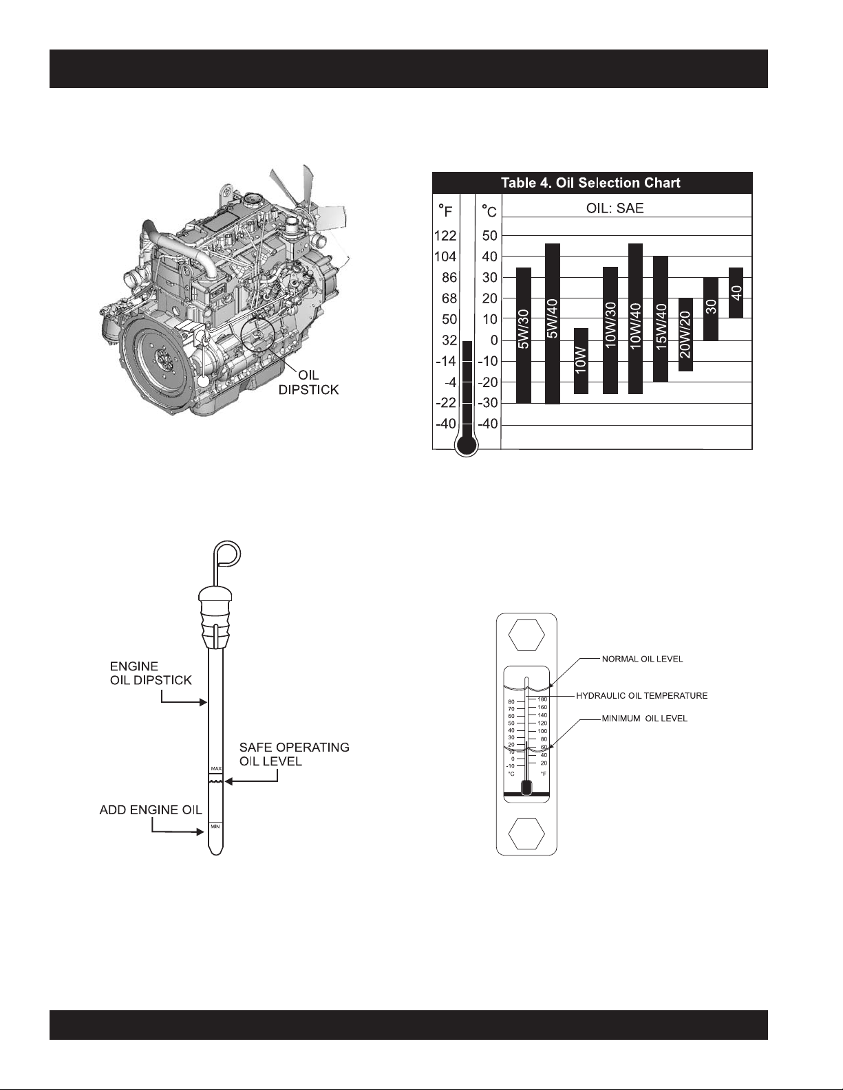
ENGINE OIL CHECK
1. Remove the engine oil dipstick from its holder
(Figure 10).
Figure 10. Engine Oil Dipstick
2. Make sure pump/engine is placed on level ground.
3. Pull the engine oil dipstick (Figure 11) from its holder.
6. The oil listed in Table 4 is recommended to ensure better
engine performance. Use class CD or higher grade motor
oil.
HYDRAULIC OIL CHECK
1. Determine if the hydraulic oil level is low by observing
the level of the oil in the Hydraulic Oil Sight Glass
(Figure 12).
Figure 11. Engine Oil Level
4. Verify that oil level (Figure 11) is maintained between
the two notches on the dipstick.
5. If the pump's engine oil is low, fill engine crankcase
with lubricating oil through filler hole, but DO NOT overfill.
PAGE 24 — MAYCO LS300 CONCRETE PUMP • OPERATION AND PARTS MANUAL — REV. #4 (06/21/10)
Figure 12. Hydraulic Oil Sight Glass
Page 25
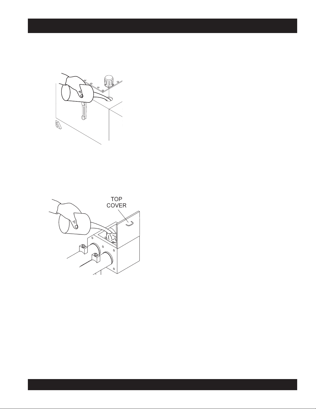
2. If the hydraulic oil level is low, remove the cap just above
the oil level sight glass (Figure 13) and add the correct
amount of hydraulic oil to bring the hydraulic oil level to
a normal safe operating level. (Use Shell oil Tellus 68 or
Mobil oil DFE26).
Figure 13. Hydraulic Oil Filler Hole
INSPECTION
3. Check the oil level in the
with up to 3 gallons of SAE #30 motor oil (Figure 14).
The oil level must be checked daily. The lubrication box
should be serviced as described in the maintenance
section.
Figure 14. Filling the Lubrication Box
lubrication box
. If low, fill
MAYCO LS300 CONCRETE PUMP • OPERATION AND PARTS MANUAL — REV. #4 (06/21/10) — PAGE 25
Page 26

LOCATION OF PUMP
1. Place the pump in the best location on the site to pump
concrete efficiently.
2. Lay down the hose in the shortest distance possible.
REAR STABILIZER JACKS
To reduce excessive vibration and rocking of the pump, set
the rear stabilizers as follows:
SET-UP
1. Locate both the left and right rear stabilizer jacks
(Figure 15).
Figure 15. Locating Rear Stabilizer Jacks
2. Remove the
and then
jack (Figure 16).
3. Position both rear stabilizers jacks on firm (not loose)
level
ground (Figure 17).
cotter pin
pull
the handle tee to release the stabilizer
from the handle tee bolt eye,
Figure 17. Rear Stabilizer Stand Deployment
NEVER place feet under jack while operating.
ALWAYS retract rear stabilizer jacks prior to towing.
ALWAYS retract rear stabilizer jacks prior to servicing to
relieve load (working pressure).
WARNING - REAR STABILIZER SAFETY
4. Align the hole on the stabilizer jack with the hole on the
frame body and
5. Insert the cotter pin into handle tee bolt eye to lock the
stabilizer jack.
Figure 16. Rear Stabilizer Jack
PAGE 26 — MAYCO LS300 CONCRETE PUMP • OPERATION AND PARTS MANUAL — REV. #4 (06/21/10)
insert
handle tee bolt.
Page 27
START-UP PROCEDURE
STARTING PROCEDURE
4. Place the
position (Figure 22).
WARNING - GENERAL SAFETY GUIDELINES
DO NOT attempt to operate this concrete pump until
FORWARD REVERSE
the Safety, General Information and Inspection
sections have been read and understood.
Figure 22. Direction Control Switch (FORWARD)
5. To start the engine, insert the key (Figure 23) into the
1. Locate the Emergency Stop Switch (Figure 19) on the
ignition switch and turn the key to the ON position.
Hydraulic Pump Control Box. Turn the Emergency Stop
switch clockwise and release (open). This will allow the
engine to start.
n
c
e
y
g
r
e
m
E
Figure 19. Emergency Stop Switch
S
t
o
p
6. When the ignition key is in the ON position, the Digital
Readout Screen (primary) will cycle through 3 displays
If the Emergency Stop switch is in the
as shown in Figure 24.
CLOSED position (stop), engine will not start.
To start the engine, make sure the
Emergency Stop switch is in the OPEN
position (fully extended).
Direction Control Switch
to the FORWARD
Figure 23. Ignition Switch
2. Turn the
Cylinder Stroke Control Switch
AUTOMATIC position (Figure 20).
AUTOMATIC JOG
Figure 20. Cylinder Stroke
Control Switch (Automatic)
3. Place the
Pumping Control Switch
to the CENTER
OFF position (Figure 21) for starting operation.
LOCAL
CENTER
OFF
REMOTE
Figure 21. Pumping Control Switch (OFF)
to the
Figure 24. Primary Screen (Ignition Key ON)
7. Turn the key to the START position and listen for the
engine to start. In warm weather let engine warm up for
5 minutes. In cold weather let engine warm up for 10
minutes.
MAYCO LS300 CONCRETE PUMP • OPERATION AND PARTS MANUAL — REV. #4 (06/21/10) — PAGE 27
Page 28
OPERATION
HOSE LUBRICATION
Before pumping, it is necessary to lubricate the hose.
PUMPING
WARNING - SAFETY GLASSES
This procedure prevents separation and blockages in the
hose. Inspect the lines at all times to prevent problems.
Before concrete is discharged into the hopper, it is suggested
that 3 to 4 gallons of water be sprayed into the hopper,
followed by approximately 5 gallons of a creamy cement and
water slurry (1/2 bag of cement to 5 gallons of water).
Getting the concrete to flow through the
hose at the start of the pumping cycle
can be one of the most critical operations of the pour.
1. Place the
PRIMING THE PUMP WITH SLURRY MIXTURE
position (Figure 26) for normal pumping operation.
It is CRITICAL to the successful operation of a concrete
pump that the manifold and all delivery hoses, pipes and
elbows are coated with a film of lubrication BEFORE you
attempt to pump concrete.
Failure to properly prepare the pump and system will result
in a “dry pack” of concrete, blocking the shuttle valve tube
or delivery line.
1. Connect the entire delivery system to the pump. Pour 5
gallons of water and a bag of raw cement into the hopper.
2. Place the
Direction Control Switch
to the REVERSE
position (Figure 25). This will mix the water and cement
Figure 26. Pumping Control Switch (LOCAL)
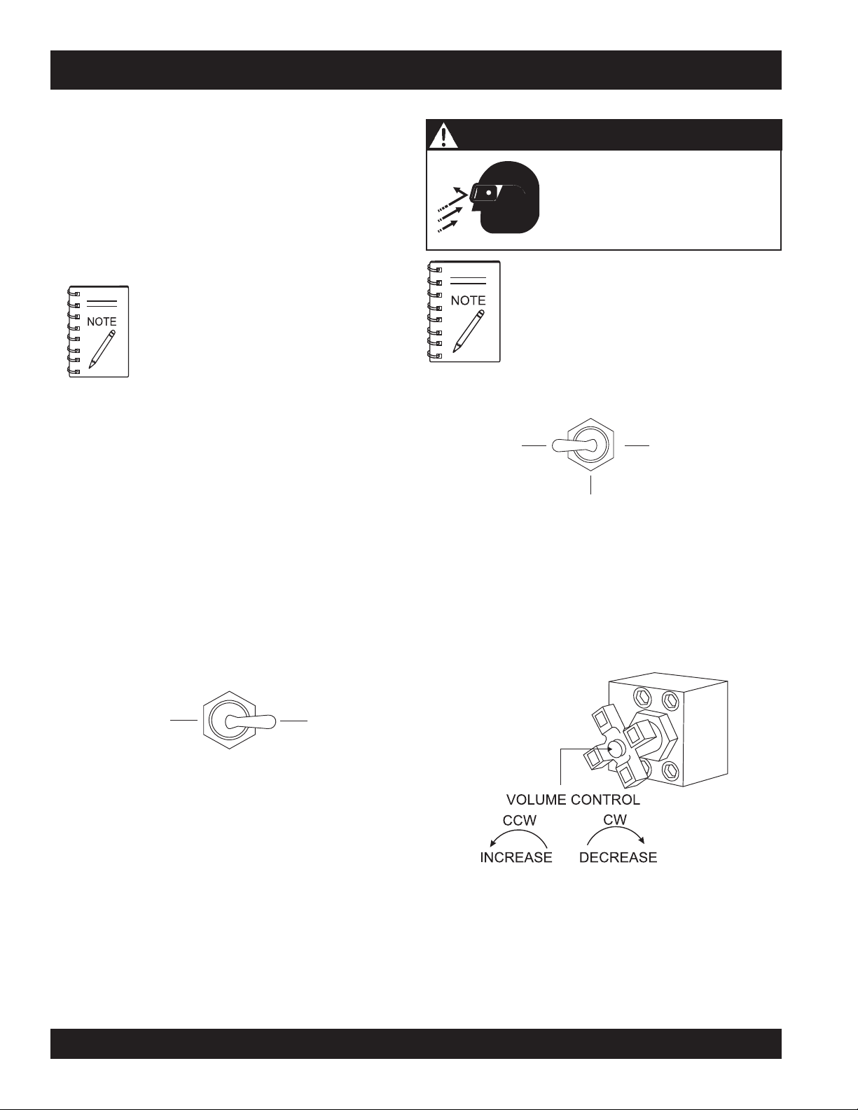
2. Use the volume control (Figure 27) to set the pump volume
to approximately 10 strokes per minute. Turning the
volume control clockwise (CW) will
and counterclockwise (CCW) will
into slurry.
LOCAL
Safety glasses MUST be worn at
all times when operating the pump.
Failure to follow safety guidelines
can result in
serious
injury.
A well-planned location of the pump and
routing of the hose before starting a pour may
save subsequent moves throughout the job.
Pumping Control Switch
CENTER
OFF
increase
to the LOCAL
REMOTE
decrease
pump volume,
pump volume.
FORWARD
REVERSE
Figure 25. Direction Control Switch (REVERSE)
3. Mix the slurry to the consistency of a smooth batter.
4. Position the first ready-mix truck at the hopper. Check
the concrete. DO NOT discharge concrete into hopper
at this time.
5. Place the
Direction Control Switch
in the FORWARD
position. This will start the flow of the slurry to the hoses.
6. Keep the slurry flowing until most of it is pumped out.
However, make sure that some slurry is left on the hopper
when concrete is first discharged from the ready-mix
truck.
PAGE 28 — MAYCO LS300 CONCRETE PUMP • OPERATION AND PARTS MANUAL — REV. #4 (06/21/10)
Figure 27. Volume Control
A
thumping
sound (cylinder stroke) should be heard. The
thumping sound represents the number of strokes per
minute (volume) of the pump.
Page 29

OPERATION
3. Scroll through the
Digital Readout Screen
with the scroll
switch to go to Screen 7 (Figure 28). This screen will show
the volume in strokes per minute.
If hoses or lines are
lines are
THROTTLE ON
STROKES: 100
STROKES/MIN 10.0
YDS/HR 0.0
Figure 28. Strokes Per Minute Display
7
cycle, the pump pressure could straighten out the kink
or force out the blockage. This rapid surge of material
could cause the lines to
that could cause injury to personnel.
6. It is important that once the slurry procedure is
completed, and concrete is flowing through the hose,
4. Let the pump cycle until the hydraulic oil temperature
(Figure 29) is approximately 50° to 60° F.
DO NOT stop the pour until all the slurry is pumped out
and the concrete has reached the end of the hose. The
only time to stop the pump during the priming procedure
is if a blockage occurs.
7. If it is necessary to replace or add a section of delivery
system, after the initial lubrication procedure, wet the
HYDRAULIC OIL
TEMPERATURE
inside area of the hose, pipe or elbow with 5 gallons of
water per 25 foot length, before adding it to the system.
CAUTION - HOSE/LINE BLOCKAGE
kinked
blocked
when starting up or during the pumping
for any reason, or if the
whip
or
move
in a manner
When pumping long distance or pumping stiff
mixes, you can expect a drop in volume
compared to shorter lines and wetter mixes
due to the change in valve efficiency or
cavitation.
Figure 29. Hydraulic Oil Temperature Gauge
5. Rotate the
Volume Control Knob
(Figure 27) to the
right to increase the volume to 25-30 strokes per minute.
Place pump control switch in the center “OFF” position.
Slowly discharge the concrete from the ready-mix truck
into the hopper and completely fill it. Place pump control
switch in the local “ON” pumping position. Keep the pump
running continuously until concrete is discharging at the
end of the delivery system. If the pumping operation
suddenly stops with no concrete discharging from the
hose, a blockage may have occurred. Immediately place
the switch in the “OFF” position. Refer to Clearing
Concrete Blockage Section.
MAYCO LS300 CONCRETE PUMP • OPERATION AND PARTS MANUAL — REV. #4 (06/21/10) — PAGE 29
Page 30
OPERATION
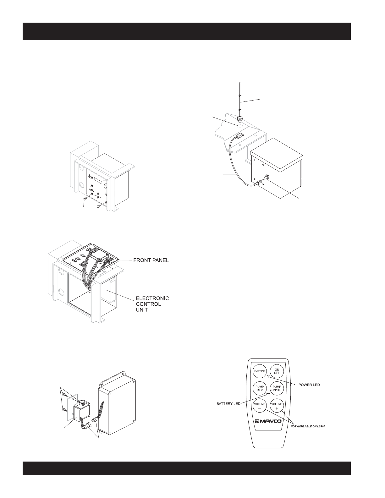
REMOTE CONTROL (OPTIONAL)
The LS300 Concrete Pump has a remote control feature
that allows the pump to be remotely controlled. If desired,
the pump can be operated via a receiver/transmitter (radio)
4. Reinstall the control panel and tighten the 2 screws.
5. On the top of the unit, to the right of the control box
(Figure 36), hammer out the knock-out hole and install
the remote antenna.
or a hardwire method, which utilizes a 25-ft. extension cable.
Contact MQ Sales Department to order remote control.
Radio Remote Control
Installation of the Radio Remote Control Assembly
KNOCK-OUT
HOLE
1. Remove the two screws on the digital control panel of
the pump. See Figure 33.
S
REMOVE 2 SCREWS
C
R
O
L
L
R
E
S
E
T
S
E
T
V
R
G
E
D
E
O
M
E
N
E
C
LU
C
R
E
Y
M
A
S
S
E
E
T
O
P
I
N
C
R
E
A
S
E
F
L
D
O
F
IR
O
W
R
E
WA
C
R
T
D
IO
N
R
E
V
E
R
S
E
C
A
O
U
O
T
N
O
F
L
T
M
F
O
A
R
C
T
O
A
I
C
L
L
O
N
R
J
E
O
M
G
C
O
E
N
T
E
T
S
E
O
T
R
F
A
F
R
C
T
Y
L
IG
I
N
D
N
E
J
R
IT
O
G
S
IO
T
“A”
R
N
O
K
E
J
O
G
“B”
R
E
M
O
T
E
CONTROL BOX
ANTENNA
CONNECTOR
CABLE
Figure 33. Removing Screws from Control Panel
2. Tilt and slowly pull out the control panel and place on
top of box to gain access inside the box. See Figure 34.
6. Connect the antenna cable to the connector on the rear
of the control box (Figure 36).
Radio Remote Control Buttons Operation
ANTENNA
REAR OF
CONTROL BOX
CONTROL BOX
CONNECTOR
Figure 36. Antenna Installation
The pumping operation can be performed by radio remote
control (Figure 37). Before using remote control, move the
Pumping Control Switch on the control box to the REMOTE
position. The buttons on the remote control have the following
functions.
ON/OFF - Turns the power on or off. When power is on the
power LED lights red. If the battery LED turns red, 9V battery
needs to be replaced.
Figure 34. Pulling Out Control Panel
3. Install the wireless remote module with the 2 screws
and nuts provided inside the control panel. Connect the
3-wire connector from the wireless remote module to
E-STOP - Turns off the pump completely in an emergency.
PUMP ON/OFF - Starts and stops the forward pumping.
PUMP REV - momentarily pumps in reverse direction.
the electronic control unit. See Figure 35.
SCREWS AND NUTS
ELECTRONIC
CONTROL
UNIT
WIRELESS
REMOTE
MODULE
CONNECTOR
Figure 35. Installing Remote Control Module
Figure 37. Radio Remote Control
PAGE 30 — MAYCO LS300 CONCRETE PUMP • OPERATION AND PARTS MANUAL — REV. #4 (06/21/10)
Page 31

OPERATION
CABLE REMOTE CONTROL UNIT
25 FT. CABLE
PUMP REV
PUMP ON/OFF
TO CONTROL BOX
CONNECTOR
Radio Remote Control Programming
Before starting operation of the Radio Remote Control, go
to Screen 9 of the Digital Readout Screen:
RADIO ADDRESS
NO RADIO
PRESS RESET TO
LEARN A NEW ONE
9
Cable Remote Control Operation
Before using cable remote control, set the pumping volume
with the VOLUME switch on the control box then move the
Pumping Control Switch on the control box to the REMOTE
position.
The cable remote control (Figure 38) has the following
controls.
1. Press the ON/OFF button on the radio (wireless) remote
PUMP ON/OFF - Starts and stops the forward pumping.
control to turn on the power. Hold down the RESET
switch. The display will now show:
RADIO ADDRESS
NOW SCANNING
FOR NEW
TRANSMITTER
9
PUMP REV - starts pumping in reverse direction.
It will be necessary at times to move your pump from
2. After 5 seconds, the display will show:
one job site location to another. Before moving the
pump, make sure to pump the remaining concrete out
RADIO ADDRESS
COMMUNICATING
PRESS RESET TO
LEARN A NEW ONE
3. The remote control is now ready for use. Release the
9
of the hopper. Moving the pump with a
concrete can cause
the axle and axle springs, excess strain and pressure
on the hub and bearing assembly.
reset switch. See Figure 6.
WARNING - TRANSPORTING PUMP
full hopper
severe damage
or breakage of
of
Cable Remote Control
Installation of the Cable Remote Control Assembly
Connect the cable to the front panel of the control box (See
Figure 38).
CABLE REMOTE CONTROL UNIT
Figure 38. Cable Remote Control
Leaking manifold seals or hose coupling
gaskets which leak water can cause separation and subsequent jamming at that point.
25 FT. CABLE
TO CONTROL BOX
CONNECTOR
MAYCO LS300 CONCRETE PUMP • OPERATION AND PARTS MANUAL — REV. #4 (06/21/10) — PAGE 31
Page 32
PUMPING INFORMATION
REMIXTURES
Remixtures that are designed into the concrete mix by the
redi-mix company or an architectural engineering company.
This section lists common admixtures and a brief explanation of their functions:
A. Pozzolith 300 – or the equivalent acts as a water
retarder and a lubricant. On a lean mix, long pushes,
stiff mixes, and vertical pushes, Pozzolith 300R
helps pumpability.
B. MBVR – air entraining, acts as a lubricant.
C. Calcium Chloride – commonly referred to as C.C.,
is used as an accelerator. When pumping a load with
calcium chloride, it is recommended that you wash
out if the waiting time between delivery trucks
becomes too long.
D. Super Plasticizers – acts as an accelerator. The
concrete will look very wet after the super plasticizer
is added, but will begin to set up very fast. Wash out
immediately if you do not have a truck waiting. Super
plasticizers are used mainly on commercial jobs.
E. Red Label – acts as a water retarder and an
accelerator. Red label will be used mainly on com-
mercial jobs.
F. Fly Ash – is used to help increase the strength of
the concrete and decrease the cement content per
yard. This is one of the most common admixtures
used.
All admixtures will be shown on the redi-mix
concrete ticket. Before starting the pumping
job, ask the driver of the redi-mix truck to see
the concrete ticket and note the admixtures
that exist and take the proper action.
DOWNHILL PUMPING
Downhill pumping can be a difficult procedure on some jobs.
The slurry procedure would be the same as explained
Priming The Pump With Slurr y Mixture
It is suggested that a sponge approximately 2”x 4”x 6” in size
be placed in the hose before the start of pumping.
Wet the sponge before placing it in the hose to keep the slurry
from running too far ahead of the concrete, which will reduce
the possibility of separation. When the pump is stopped, the
material can flow slowly down, due to gravity, and cause the
hose to collapse.
section of this manual.
When pumping is resumed, you can expect blockage at the
point of hose collapse. To prevent this from happening, the
hose can be “kinked off ” at the discharge end when the pump
is stopped to prevent the gravity flow of the material in the
hose.
The use of stiffer mixes when pumping downhill will decrease
gravity flow of the material in the hose and will assure a
smoother operation between the cam roller bearing and cam
plate. As with any job, make sure that the hose and the
couplings are in good workable shape.
VERTICAL PUMPING
When pumping vertically up the side of a building, above 40
feet, we would recommend the installation of
securely fastened at intervals as necessary to support the
pipe. Ninety degree, long radius pipe sweeps should be
installed at the top and bottom of the steel line.
Use a 25 ft. hose, or short section, off the pump; and for the
balance of the horizontal distance to the vertical line, use
steel pipe. This type of installation has been satisfactory on
many jobs being pumped in excess of 100 feet high. Line
pressures are always less using steel pipe as compared to
hose.
When pumping vertically, using
not to go higher than 50 feet with hose. The hose should be
tied off at intervals of 10 feet, if possible. Special attention
should be given when tieing the hose off at the top as the hose
will have a tendency to stretch when filled with concrete. This
will increase the possibility of a blockage at the point where
the hose is tied off. To avoid this, a long radius of 90º elbow
is recommended. The suggested place to tie off is on the
hose, under the clamp.
HOSE PULSATION
A slight pulsation of the hose will always be noticeable near
the pump. Excessive pulsation of the hose near the pump is
normally due to higher than average line pressures caused by
stiff, harsh mixes, or extremely long pumping distances.
steel pipe
all hose
It is strongly recommended that
be used on all vertical pumping for safety and
convenience.
, it is recommended
steel pipe
PAGE 32 — MAYCO LS300 CONCRETE PUMP • OPERATION AND PARTS MANUAL — REV. #4 (06/21/10)
Page 33

PUMPING INFORMATION
The use of 2 -1/2” I.D. hose in these extreme cases reduces
line pressures or the addition of slight amounts of water to the
mix, if permissible, will permit easier pumping. The use of
certain pumping admixtures may help.
If excessive pulsation exists in the hose, it is advisable to
use burlap or some means of wear protection under the hose
at points where the hose may wear through the outer cover;
e.g. over forms, steel or sharp curbs.
SNAP-JOINT COUPLINGS
When using Snap-Joint couplings with gaskets to join hose,
see that they are washed clean after each job. Keeping the
hose ends clean (heavy duty) is very important for the best
job setup. A thin coat of grease on the rubber gasket or
dipping both coupling and gasket in water before coupling the
hose will make for easier installation.
NEW PUMPS
All new pumps are ‘water pressure tested” at the factory This
procedure permits a thorough inspection of entire drive
system and valving under simulated full load conditions. The
pump owner can do the same by making an adapter to couple
to the end of the discharge cone: e.g., the use of a standard
2" pipe cap with a 3/8" drilled hole in the center, screwed on
to the end of hinged cone or reducer at the pump.
Fill the hopper with water after making sure that all sand and
rock have been removed from manifold. Operate pump at full
throttle and the 3/8" diameter hole restriction will create
sufficient back pressure to make thorough inspection of all
moving parts.
THE EFFECTS OF HEAT AND EXCESSIVE
TIME ON CONCRETE:
Hot concrete, commonly referred to as a hot load, is concrete
that has been in the redi-mix truck in excess of 2 to 3 hours.
On a hot day, this amount of time is even less.
A brief explanation of why heat and time affect concrete:
Concrete starts setting by drying up through a chemical
reaction. The catalyst to this reaction is heat. When
pumping a hot load, it is important to remember that
when you have to stop pumping for any reason, add
water to the concrete in the hopper and hand mix and
move concrete in the hose every 5 minutes. If the shut
down time becomes too long, wash out
immediately
If it is necessary to wait 1/2 hour or more for another load of
concrete, to prevent setting of the mix in the system, it is
advisable to consider the following factors (
affecting the concrete:
A. How old is the concrete?
B. Is there an accelerator, calcium chloride, red label,
C. The temperature of the day, 80, 90, degrees?
D. How much system you have out and how stiff was
PREVENTING MIX SET-UP AFTER PUMP SHUTDOWN
When the pump is stopped for any reason during a pour; e.g.,
moving hose, waiting for redi-mix truck, the following suggestions are offered:
1. Leave the hopper full of concrete at the time of shutdown.
It is important not to let the
much water into the hopper, as this could cause separation of the concrete in the hopper.
2. If the
the engine so the vibration does not separate the mix in
the hopper which can cause a blockage in the manifold
when the pump is started.
3. If it is necessary to wait 10 minutes or more for another
load of concrete, it is wise to start the pump and pump
6 or 8 strokes every 5 minutes to prevent setting of the
mix in the system. If waiting time is excessive, it would
be wise to wash out the pump and hoses and start over
when the new truck arrives.
4. When pumping stiff mixes and there is waiting time
between redi-mix trucks, it is advisable to add some
water to the last hopper of material and “hand mix” to
ensure an easier start with the following load.
5. When the pumping job requires a stiffer mix, the following
method is suggested for starting: Take a water hose with
a nozzle on it and apply water with a fine spray to the
concrete as it comes down the redi-mix chute into the
.
pump hopper after the slurry procedure is completed and
you are ready to start pumping.
etc., in the concrete?
the mix you were pumping?
redi-mix
shutdown
period exceeds 2 to 3 minutes, turn off
A through D
driver wash too
)
MAYCO LS300 CONCRETE PUMP • OPERATION AND PARTS MANUAL — REV. #4 (06/21/10) — PAGE 33
Page 34
PUMPING INFORMATION
Using this procedure will make it easier to pump through
the clean hose. Note: Once the concrete has reached the
end of the hose, do not apply any more water in this
manner as this procedure is used for starting only.
6. Hose sizing is very important: We strongly recommend
on harsh mixes, vertical pushes, stiff concrete, shotcrete,
long pushes, that a 2 -1/2” line be used as far as possible.
The advantages of using the 2 -1/2” line are improved
pumpability, less pumping pressure and less wear on the
pump.
7. Following the pump operation, proper wash out of all
materials or “build-up” within the pump manifold and
hoses will prevent problems when starting the next job.
8. A thorough inspection of the drive components and
greasing of all bearings after each job will ensure adequate lubrication and service to the pump which is
normally operating in wet, gritty conditions.
Over-greasing any
pump will not damage the bearing.
bearing
on your Mayco
4. If waiting time is excessive, it would be wise to wash out
the pump and hoses and start over when the new truck
arrives. This can be avoided by being observant to the
pump and system, also taking into consideration the
above actors (A through D) affecting the mix.
CLEARING CONCRETE BLOCKAGE
If you repeatedly pull the throttle all the way out and
try to force your pump to push through
due to separation of material in the hose or manifold,
you will soon have breakdowns and costly repairs which
are not covered under warranty.
If a blockage occurs, find where it is and clear it before
further pumping. DO NOT increase the engine speed
to clear the blockage. Increasing the engine speed
will only compound the problem.
If a blockage occurs in a hose,
the point of trouble. The hose will be soft immediately past the
blockage. To clear the blockage:
WARNING - BLOCKAGES
walk the hose
blockages
until you find
1. Disconnect the hose at the first coupling past the
blockage.
CLEARING THE SYSTEM AFTER MIX SET UP
If, for any reason, the mix should set up in the system, the
following procedure is suggested:
1. Disconnect the hose from the pump and wash the pump
out immediately.
WARNING - HOSE/LINE PRESSURE
When disconnecting hoses, use EXTREME
CAUTION! The hose is under pressure!
2 Reconnect the hose and fill the hopper with water.
3. Reconnect the hose and fill the hopper with water. DO
NOT try to push all the concrete out of all of the hose lines
at one time.
For example: If you had 200 ft. of system out, you would
disconnect each hose. Clean it out by pushing water
through the first hose off the pump, then continue
progressing through all the hoses, until all the system is
clean.
WARNING - HOSE LINE PRESSURE
Use extreme care! The hose line is under
and can cause serious injury.
2. Elevate the hose at that point with the blockage area
hanging down.
3. Using a hammer, you can pound the downstream edge
of the packed area until it is free to flow. Shake all of the
sand and gravel out to the end of the hose.
4. Before reconnecting the hose, start the pump and run a
small amount of concrete out to the end of the hose. This
will assure that all of the separation is out of the hose.
pressure
Damaged hoses with internal restrictions can
cause blockages.
PAGE 34 — MAYCO LS300 CONCRETE PUMP • OPERATION AND PARTS MANUAL — REV. #4 (06/21/10)
Page 35

PUMPING INFORMATION
CLEARING SHUTTLE TUBE BLOCKAGE
The shuttle tube is plugged if volume at the discharge end of
the hose stops and the hydraulic oil pressure gauge reads
3100 PSI or more.
To clear a plug in the shuttle tube, great care must be taken
as a dangerous condition will exist from pressure build-up
inside the shuttle tube. (With the shuttle valve, the concrete
can be pumped in reverse.) Use the following procedures to
clear the shuttle tubes.
WARNING - SHUTTLE TUBES
DO NOT open any of the delivery system joint clamps.
“REVERSE” PUMPING PROCEDURE
A. Switch the pump into REVERSE. With pump speed
at a medium-slow (approx. 12 strokes per min.) try
to pull the “pack” back into the hopper with 5 or 6
reverse strokes.
B. Switch the pump into FORWARD. If it is still plugged,
repeat “Reversing” procedure three times.
E. Chip the concrete out of the reducer with the pry
F. Remove the reducer. From the discharge end, chip
G. Chip the blockage out with the pry-bar.
H. Flush the shuttle tube with water.
I. Before resuming operation of the pump, perform the
bar.
the concrete out of the shuttle tube with the pry-bar.
If concrete cannot be loosened from the outlet of
the shuttle tube, remove the clean-out plug on the
bottom of the hopper to discharge the concrete.
“Reverse” Pumping Procedure to relieve pressure
on the shuttle tubes.
If concrete still does not move, proceed to the Shuttle Tube
Inspection Procedure.
WARNING - PRESSURE GAUGE
Make sure the pressure gauge reads ZERO psi. prior
to performing any maintenance or inspection.
SHUTTLE TUBE INSPECTION PROCEDURE
A. Stop the pump. Switch off the engine.
B The senior or most experienced operator must warn
all others to stand at least 20 feet away from the
machine and turn their heads to face away from the
pump.
C. The operator will position himself beside the reducing
elbow at the pump outlet. Wearing
slip the end of a pry bar (24" length of reinforcing
steel rod) under the latch of the hose clamp and flip
it up.
safety glasses
,
D. Carefully knock the end of the hose away from the
reducer.
MAYCO LS300 CONCRETE PUMP • OPERATION AND PARTS MANUAL — REV. #4 (06/21/10) — PAGE 35
Page 36

MAINTENANCE (PUMP)
ELUDEHCSKCEHCECNANETNIAM.5ELBAT
yliaDylruoHylkeeWylhtnoMshtnoM-6
liOenignEXX
retliFriAenignEX
retliFleuFX
leveLliOciluardyHX
tacirbuLX
xoBnoi
liOciluardyHecalpeR .srh005
sretliFciluardyHnaelCX.srh0012
knarCelxAX
stnioPkreZebuTelttuhSesaerGXsrh2
erusserPmetsySkcehCX.srh04
ssenthgiTroferawdraHkcehCX.srh04
etalP/gniReraWgnittuCkcehCX
kcehCX
sthgiLekarBkcehCX
noitcnuFsekarBreliarT
snoitidnoCeriTkcehCX
slaceD/seciveDyetfaStcepsnIX
lanoitarepO
sruoH
sgniraeBleehWkcehC X
yrettaBkcehCX
niLekarBtcepsnI X
gni
skaeLliOrofkcehCyllausiVX
CLEANING THE PUMP AND DELIVERY SYSTEM
DANGER - AMPUTATION RISK
You will be required to put your hand in the concrete
cylinders or near the shuttle tube. You are at
EXTREME RISK
of injury or
AMPUTATION
if the
engine is running or if pressure is in the hydraulic
system.
Prior to performing any
Cleaning the pump is a very important operation as it
determines how the machine will pump the next time it is
used.
At the end of every pour, or because of long delays during a
pour, the pump and delivery system must be thoroughly
cleaned by removing all concrete material.
1. Following the Clearing Concrete Blockage operating
maintenance on the
pump, stop the engine by
turning off the ignition
switch and remove the
starter key. Place a “DO NOT OPERATE” tag over
2. Pump concrete until the opening of the concrete cylinder
the switch and disconnect the battery. The main
pressure gauge reading
MUST
read ZERO.
3. Stop the pump.
procedure, ensure that there is no blockage in the hose
and line or in the shuttle tube (using the Shuttle Tube
Inspection Procedure). If a blockage exists, clear it.
intake in the hopper is visible.
4. Carefully disconnect the first hose joint at the shuttle
tube discharge elbow.
PAGE 36 — MAYCO LS300 CONCRETE PUMP • OPERATION AND PARTS MANUAL — REV. #4 (06/21/10)
Page 37
MAINTENANCE (PUMP)
5. Add water to the hopper. Pump and flush clean the entire
hopper, shuttle tube and discharge elbow with water.
6. Scoop out 12 inches of concrete from the inboard end
of the delivery hose. “Cork screw” a 6" x 6" x 8" sponge
into the end of the first hose section. Reconnect the
hose to the discharge elbow.
7. Fill hopper with water. Pump until sponge and clean water
come out the discharge end of the hose and line system.
8. When the pump has been used to pump small aggregate
concrete (pea rock, ½" minus) or mixes with high fines
content (60% or more sand) there will be a tendency for
hardened concrete to build up on the inside surface of
the shuttle tube. Therefore, at the end of every such
pour, after the pump and system have been cleaned
and the engine shut off, remove the shuttle tube
inspection plate (follow the Shuttle Tube Inspection
Procedure) and remove all remaining concrete.
9. When the pump has been used to pump large aggregate
concrete (" to 1 (" follow the instructions in step 8 once
per week.
WARNING - ACID CLEANING
HYDRAULIC OIL SYSTEM MAINTENANCE
The Mayco pump is equipped with an in-tank return hydraulic
filter with a 10 micron cleanable filter. The element has been
designed to remove all particles large enough to cause wear
and job break down. Under normal conditions, we recommend
cleaning every 6 months.
The most important factor to keep in mind is the effect of
cold weather on the hydraulic oil. The viscosity (thickness)
of the hydraulic oil will be much heavier.
ALWAYS run machine until oil temperature reaches a
minimum of 50°F. before pumping. Damage to the main piston
pump will occur if the machine is cycled too fast before the
oil temperature reaches the minimum of 50°F. Cycle the
machine at 6-8 strokes per minute at approximately 1/3
throttle.
In areas where the weather normally remains
use Shell Oil Tellus 46 (or the equivalent). The above steps
must be followed or severe damage to the main axial piston
pump can occur.
1. When changing the hydraulic oil or topping off the
reservoir, use only the following type.
(Reservoir capacity - 33 gal.)
under 50°F
.,
NEVER use muriatic acid to clean the pump. Acid will
dissolve the chrome finish on material cylinder bore
and main hydraulic cylinder rods.
Use only a 2½" diameter clean-out hook
when back-pumping into redi-mix truck. Use
a safety chain to secure the clean-out hook
to some solid part of the mixer truck to
prevent hook from jumping off of the drum.
Run the pump at 6 strokes per minute
maximum speed.
Deutz Model TD2009L04 Diesel Engine
This pump is equipped a Deutz TD2009L04 turbo diesel engine.
For information concerning the procedure in checking, removing,
cleaning, etc. of the various engine parts or any other information
on the engine not contained herein, refer to the engine
manufacturer’s instruction manual.
Hydraulic oil: Shell Oil Tellius 68 or
WARNING - HYDRAULIC OIL
DO NOT mix oil brands! This may impair quality.
2. Lubrication: Grease daily/Hour
(Recommended after each Pour)
■
Main hydraulic cylinders - 2 Place
■
Axle crank - 1 Place
■
Shuttle cylinders - 2 Place
■
“S” tube outlet flange - 3 Place
Grease Type: Lithium Based EP
Mobil DFE 26
Texaco Rand HDC
Texaco Multitak 20
Lubriplate ED-2
MAYCO LS300 CONCRETE PUMP • OPERATION AND PARTS MANUAL — REV. #4 (06/21/10) — PAGE 37
Page 38

MAINTENANCE (PUMP)
BATTERY MAINTENANCE
CAUTION - BATTERY MAINTENANCE SAFETY
Wear
protective clothes, and rubber gloves when
working with battery.
Mishandling of the battery shortens the service life of the
battery and adds to maintenance cost. When handling the
battery do the following:
safety glasses
Be careful not to let the battery electrolyte come in
contact with your body or clothing.
Always wear
the battery contains sulfuric acid which burns skin and
eats through clothing.
Always check the battery terminals periodically to
ensure that they are in good condition.
Use wire brush or sand paper to clean the battery
terminals.
Always check battery for cracks or any other damage.
If white pattern appears inside the battery or paste has
accumulated at the bottom, replace the battery.
If the pump will not be in operation for a long period of
time, store in cool dry place and check the battery charge
level every month to maintain the performance of the
battery.
Check the battery regularly and make sure that each
electrolyte level is to the bottom of the vent well
(Figure 39). If necessary add only distilled water in a
well-ventilated area.
eye protection
or
face mask
and
rubber gloves
,
, since
BRAKE SYSTEM
The brake system should be periodically checked. Look for
fluid leaks worn or cracked hoses. Check the reservoir for
proper fluid levels. The Atwood surge brake should be
checked for damage. Make sure that all links and pivots are
kept lubricated.
1. Keep all links and pivots lubricated to prevent rusting
and ensure ease of operation. Using SAE 30 oil, lubricate
inside the release handle and inside the actuator body.
This can be reached from the underside of the actuator.
Lubricate the hitch ball with conventional
automotive grease or a lubricant made for
hitch balls.
2. Check for any leaks in the brake system. Periodic checks
should be made on all hoses to guard against cuts and
worn hoses which may cause failure (leaks, rupturing
under pressure, and collapsing). Replace defective hoses.
CAUTION - MASTER BRAKE CYLINDER
DO NOT fill the master cylinder reservoir with used
brake fluid. DO NOT fill the reservoir beyond ½" from
top. DO NOT overfill; brake fluid will damage paint.
3. Check the brake fluid level in the master cylinder reservoir.
Keep it filled to within ½" from the top of the reservoir.
4. At the beginning of each year, inspect the brakes for
excessive wear, replace the linings if necessary.
Wheel bearings and seals should be
inspected and packed at this time.
Figure 39. Battery Electrolyte Levels
PAGE 38 — MAYCO LS300 CONCRETE PUMP • OPERATION AND PARTS MANUAL — REV. #4 (06/21/10)
Page 39
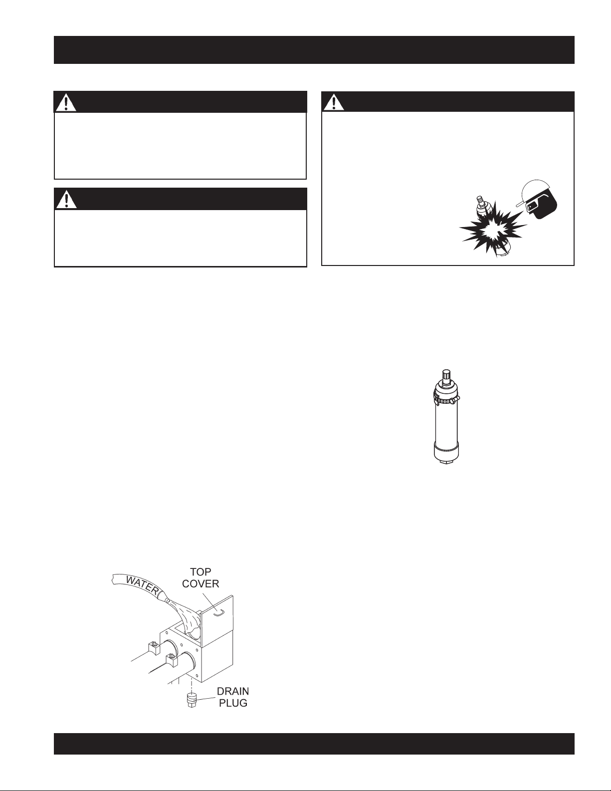
MAINTENANCE (PUMP)
CYLINDER LUBRICATION BOX
WARNING - FREEZING CONDITIONS
When using the pump during freezing conditions,
completely drain the water box and cover the hopper
after pumping. Frozen liquid will restrict the piston travel
and cause
severe damage
to the pump.
ACCUMULATOR CIRCUIT
Improper accumulator charging can result in an explosion
causing serious injury or death! NEVER use oxygen or
compressed air to charge the accumulator! Only qualified
personal should perform this procedure. Use only
nitrogen
CAUTION - SAFETY GUIDELINES
Before checking lubrication level, stop the engine and
remove the engine starter key.
1. The lubrication level should be checked everyday prior
to pumping and maintained at a height of 5 inches or
about ½ the concrete cylinder height. We recommend a
using a 30 weight motor oil.
2. As the rubber piston cups naturally wear, fine cement
particles will accumulate in the box. Once the concrete
paste reaches a height of about ½ inch from the bottom
of the box, drain and clean the lubrication box.
accumulator. Contact your
Mayco service department
or your local Parker
representative for proper
charging procedure.
The accumulator circuit stores oil under pressure and releases
it to the pilot value to ensure enough pressure is provided to
operate the valve.
The accumulator circuit is equipped with a piston type
accumulator (Figure 41) pre-charged at the factory with 500 PSI
of dry nitrogen.
DANGER - ACCUMULATOR CHARGING
dry
to charge the
CLEANING THE LUBRICATION BOX
1. Remove the top cover and the drain plug (Figure 40)
located at the bottom of the box and fully drain the inside
of the box.
2. Once the box is drained, start the engine and stroke the
cylinder (
3. While stroking, spray water inside of the box to
thoroughly clean out all contamination (Figure 40).
4. When the box is clean replace drain plug, add new
lubrication and install the top cover.
keep hands out of box
) ten to fifteen times.
Figure 41. Accumulator
Figure 40. Cleaning the Lubrication Box
MAYCO LS300 CONCRETE PUMP • OPERATION AND PARTS MANUAL — REV. #4 (06/21/10) — PAGE 39
Page 40
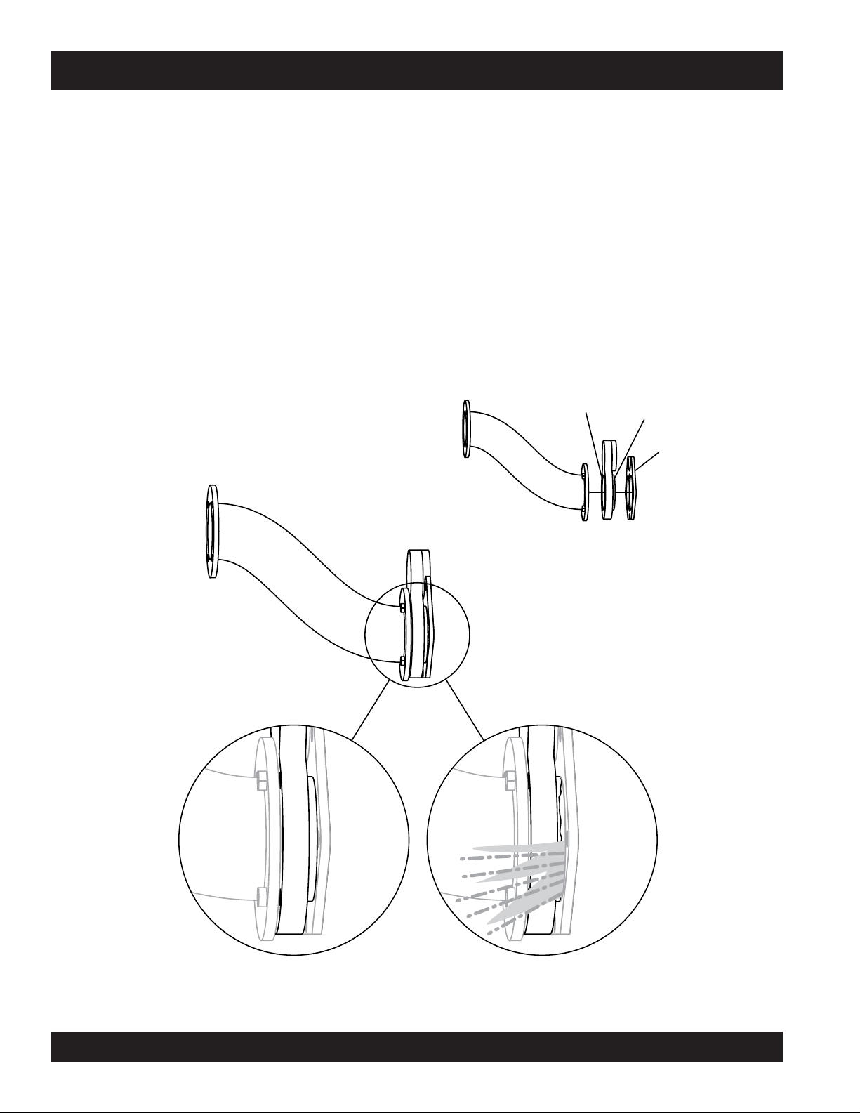
MAINTENANCE (PUMP)
WEAR PLATE AND CUTTING RING
Due to the abrasive nature of concrete, it is normal for the
cutting ring to wear on its sides as it shears through the
concrete inside the hopper. The metal-to-metal friction and
the abrasiveness of the concrete will cause extreme wear
and reduce sealing capability between the cutting ring and
wear plate. If the two components do not properly seat
against each other, slurry will pump into the hopper rather
than out the discharge line. See Figure A. This condition
can easily be observed:
1. The sudden change of the level of concrete inside the
hopper during each pumping stroke
2. Concrete slurry squirting into the air from the hopper
(Volcano effect)
3. When the output volume at the end of the delivery line
decreases in pressure
4. Unusual frequent material packs in the Shuttle tube
6+877/(78%(
,16,'(+233(5
It is important that the wear components be inspected
weekly for proper sealing. Failure to inspect will
eventually cause severe damage to the nun-plate and
material cylinders. Visually inspect wear plate and
cutting ring to ensure surfaces are sealed against each
other. If a deep groove or a wide space has developed
on the sealing surfaces, it is time for replacement.
Due to the motion of the Shuttle tube, the cutting ring
experiences a quicker rate of wear as opposed to the wear
plate. The wear ring typically requires replacement two times
per wear plate (2 to 1). When replacing the wear ring, also
replace the rubber energizer ring.
58%%(5
(1(5*,=(5
&877,1*
5,1*
:($5
3/$7(
*22'6($/ /($.,1*
Figure A. Wear Plate and Cutting Ring
PAGE 40 — MAYCO LS300 CONCRETE PUMP • OPERATION AND PARTS MANUAL — REV. #4 (06/21/10)
Page 41
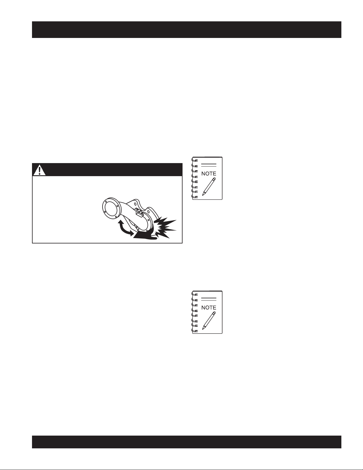
MAINTENANCE (PUMP)
CHANGING THE CONCRETE CYLINDER PISTON CUPS
The Rubber piston cups will occasionally require replacement
depending on the following factors.
■
The fluid level and cleanliness of the lubrication box.
■
The size and type of aggregate.
■
The type of concrete being pumped.
It is time to replace the cups when increasingly large particles
of sand and cement pass into the lubrication box. Do not
allow the cups to become so worn that they begin to pass
lubrication into the material cylinders. If the liquid level of
the lubrication box becomes to low, the rubber cups will
severely deform due to excessive heat. Whenever
replacement is due, both cylinder cups should be replaced.
WARNING - AMPUTATION RISK
To prevent accidental cycling of any pump components,
ALWAYS shut engine
off, remove ignition keys
and disconnect battery
prior to performing any
maintenance on the
pump.
CYLINDER CUP REPLACEMENT PROCEDURE
1. Remove the two hydraulic hoses connected to the remix
motor. Plug the ports with fittings (not provided) to
prevent hydraulic hose leakage.
6. Remove the three 3/8 – 16 x 3” bolts from the piston.
Remove the front faceplate.
7. Install two the 3/8’ 16x3” bolts back into the piston –
do not tighten. Use the two bolts as leverage to remove
the rubber piston cup and rear components.
8. Obtain two 3/8 16x7” full thread studs (these studs will
be used to assist in assembly alignment) insert the
two studs into the piston adapter. Coat the concrete
cylinder with grease.
9. Install the “O” Ring around the oiler plate. Install the
plate into the concrete cylinder utilizing the studs for
alignment.
10. Install the felt holder over the oiler plate. Install felt ring
into felt holder. Install the bronze ring.
11. Using silicon sealant place a small bead of sealant
material on the front of the rubber piston cup and the
rear of the face plate. Install over alignment studs and
into concrete cylinders.
12. Insert one 3/8” 16x3” bolt into the open bolt hole, remove
the alignment studs one at a time and install the
remaining 3/8” 16x3” bolts.
Felt ring must be saturated with 30 wt. oil
prior to installation.
2. Remove the hopper discharge nipple and loosen sleeve
seal. Inspect and replace if wear is excessive.
3. Remove the two tie rod nuts and the four eyebolt nuts
securing the hopper to the pump frame.
4. Using an approved lifting device, remove the hopper
using extreme care not to damage the hopper seal.
5. Start the engine and turn on the pressure test switch.
Cycle pump in reverse until hydraulic system obtains
maximum pressure, then turn pump and engine
off.
Remove ignition key and disconnect battery. Think
safety! Check the hydraulic gauges on panel and make
sure accumulator pressure reads zero. One piston
should be in the fully discharged position at the end of
the concrete cylinder.
MAYCO LS300 CONCRETE PUMP • OPERATION AND PARTS MANUAL — REV. #4 (06/21/10) — PAGE 41
Before installing 3/8” bolt, coat the back of
bolt heads with silicon sealant. Torque all three
bolts equal at 55 ft. lbs. each.
Page 42

MAINTENANCE (PUMP)
CHANGING THE WEAR PLATE AND RING
Due to the swinging motion of the Nun-plate and the abrasive
nature of concrete, it is normal for the cutting ring to wear on
the side that shears through the concrete inside the hopper.
If the wear ring and wear plate do not fully seat against each
other the concrete slurry will pump into the hopper. This
condition can be easily observed by the sudden change of
the level of concrete inside the hopper during each stroke.
Wear Plate and Ring Replacement Procedure
1. Remove the two hydraulic hoses connected to the remix
motor. Plug the ports with fittings (not provided) to
prevent hydraulic hose leakage.
2. Remove the hopper discharge nipple and loosen sleeve
seal. Inspect and replace if wear is excessive.
3. Remove the two tie rod nuts and the four eyebolt nuts
securing the hopper to the pump frame.
4. Using an approved lifting device, remove the hopper
using extreme care not to damage the hopper seal.
5. Remove the four 1/2” 1-¼” bolts that hold the shuttle
tube to the nun-plate and remove shuttle tube.
Using two small pry bars remove the rubber energizer
ring, steel insert ring and wear ring.
Wear Plate Installation
1. Install the two cylinder “O” rings.
2. Using silicon sealant, coat the circumference of the
concrete cylinders, the back of the wear plate and around
the five bolt holes. Next, install the wear plate and the
five bolts. The bolts must all be equally snugged and
tightened to 100 foot pounds each.
Wear Ring installation
1. Install the wear ring into the nun plate.
2. Install the steel insert ring inside of the rubber energizer
ring.
3. Install the energizer ring assembly into the nun-plate.
After installing the above mentioned components the
machine can be reassembled by reversing steps 1 through
5 of the Wear Plate and Ring Replacement Procedure.
HEAT EXCHANGER COOLING FAN
This section is intended to make sure the fan is working
properly. Under normal conditions the fan should be running
any time the engine is turned on.
CAUTION - HYDRAULIC OIL TEMPERATURE
If the hydraulic oil temperature exceeds 170 degrees
The energizer ring and wear ring will
normally have concrete contamination
holding them in position. It will be required
to chip some of the concrete loose to
better expose the energizer ring.
6. Clean out all concrete build up in and around the nunplate area with a wire brush.
7. Inspect the wear components for indications of wear.
The wear plate has two wear surfaces.
Fahrenheit, shut down the pump. DO NOT continue
to operate the pump. Failure to shut down the pump will
result in severe damage to the pump.
PAGE 42 — MAYCO LS300 CONCRETE PUMP • OPERATION AND PARTS MANUAL — REV. #4 (06/21/10)
Page 43
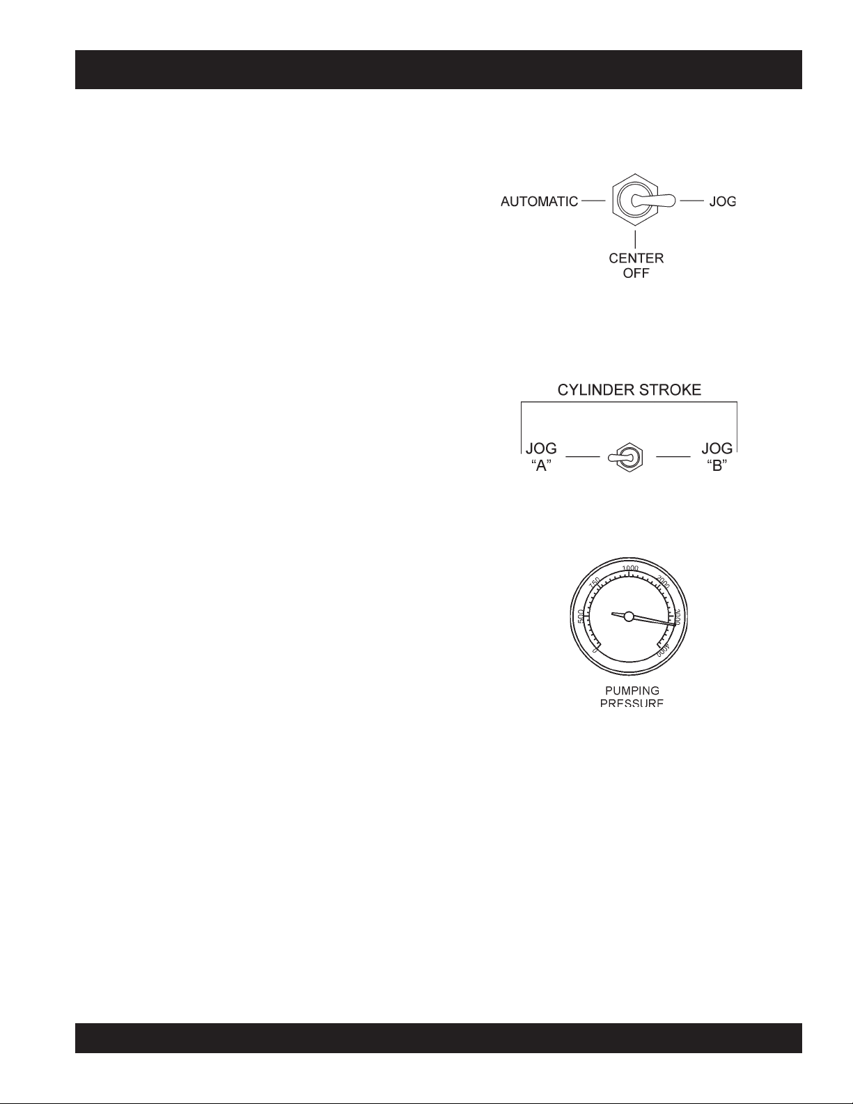
MAINTENANCE (PUMP)
WHEEL BEARINGS
After every 6 months of operation inspect the wheel bearings.
Once a year, or when required, disassemble the wheel hubs
remove the old grease and repack the bearings forcing grease
between rollers, cone and cage with a good grade of high
speed wheel bearing greases (never use grease heavier than
265 A.S.T.M. penetration “No. 2.”).
1. Fill the wheel hub with grease to the inside diameter of
the outer races and also fill the hub grease cap.
2. Reassemble the hub and mount the wheel. Then tighten
the adjusting nut, at the same time turn the wheel in
both directions, until there is a slight bind to be sure all
the bearing surfaces are in contact.
3. Back off the adjusting nut 1/6
locking hole or sufficiently to allow the wheel to rotate
freely within limits of .001” to .010” end play. Lock the
nut at this position.
4. Install the cotter pin and dust cap, and tighten all
hardware.
to 1/4 turn or to the nearest
PRESSURE TEST
1. To determine the pressure of the Hydraulic System, set
the
Cylinder Stroke Control Switch
JOG position.
Figure 42. Cylinder Stroke Control Switch (JOG)
2. Turn and hold the Manual Cylinder Jogging Switch
(Figure 43) to either JOG “A” or JOG “B” position to
test the pressure of that cylinder.
Figure 43. Manual Cylinder Jogging Switch
(Figure 42) to the
EXTENDED STORAGE INSTRUCTIONS
The following preventative maintenance is recommended
for extended periods of storage.
1. Check brake system for proper fluid level in master
cylinder and bleed all lines.
2. Lubricate all links and pivots to prevent any rusting.
3. Remove wheel and drum assemblies and spray a good
anti-corrosion compound (CRC formula 5-56) under rubber
boot on forward end of brake wheel cylinder. Avoid
spraying drum and brake lining.
4. Grease all bearings and reinstall wheel and drum
assemblies.
5. Make sure breakaway cable is fully released.
6. After extended storage, refer to the Maintenance Steps
listed above to insure that the trailer is ready for towing.
13. The Pumping Pressure Gauge (Figure 44) should read
approximately 3100 ± 50 PSI.
Figure 44. Pumping Pressure Gauge
MAYCO LS300 CONCRETE PUMP • OPERATION AND PARTS MANUAL — REV. #4 (06/21/10) — PAGE 43
Page 44

MAINTENANCE (TRAILER)
The following trailer maintenance guidelines are intended to
assist the operator in preventive maintenance.
You must check the fluid level in the master cylinder
reservoir at least every three months. If you tow your trailer
an average of 1,000 miles per month in a hot and dry
Trailer Brakes
Properly functioning brake shoes and drums are essential to
ensure safety. The brakes should be inspected the first 200
miles of operation. This will allow the brake shoes and drums
to seat properly. After the first 200 mile interval, inspect the
brakes every 3,000 miles. If driving over rough terrain, inspect the brakes more frequently.
Hydraulic Brakes
If your trailer has hydraulically-operated brakes, they
function the same way the hydraulic brakes do on your tow
environment, you must check the brake fluid level once a
month. The brake fluid reservoir is located on the tongue of
the trailer. Always fill with clean, uncontaminated DOT 4
brake fluid.
Figure 45 below displays the major hydraulic/air/surge brake
components that will require inspection and maintenance.
Please inspect these components as required using steps
1 through 6 as referenced in the “Manually Adjusting The
Brakes” section on this page. See Table 11 Trailer Brake
System Troubleshooting.
vehicle. The hydraulic braking system must be inspected at
least as often as the brakes on the tow vehicle, but no less
than once per year. This inspection includes an
assessment of the condition and proper operation of the wheel
cylinders, brake shoes, brake drums and hubs.
Manually Adjusting the Brakes
Most axles are fitted with a brake mechanism that will
adjust the brakes during a hard stop. However, some
braking systems are not automatically adjusted by hard
stopping. These brakes require manual adjustment. The
following steps apply to adjust most manually adjustable
brakes.
1. Jack up the trailer and secure it on adequate capacity
jack stands.
2. Be sure the wheel and brake drum rotate freely.
3. Remove the adjusting-hole cover from the adjusting slot
on the bottom of the brake backing plate.
Figure 45. Hydraulic Brake Components
Hydraulic Brake Actuator
The hydraulic brake actuator (Figure 46) is the mechanism
that activates the trailer’s brake system. This actuator
changes fluid power into mechanical power. Therefore, the
fluid level must be checked frequently to assure that the
brakes function properly.
4. With a screwdriver or standard adjusting tool, rotate the
starwheel of the adjuster assembly to expand the brake
shoes. Adjust the brake shoes out until the pressure of
the linings against the drum makes the wheel very
difficult to turn. Note: Your trailer maybe equipped with
drop spindle axles. See axle manual for your axle type.
You will need a modified adjusting tool for adjusting the
brakes in these axles. With drop spindle axles, a
modified adjusting tool with about an 80 degree angle
should be used.
5. Rotate the starwheel in the opposite direction until the
wheel turns freely with a slight drag.
6. Replace the adjusting-hole cover.
7. Repeat the above procedure on all brakes.
8. Lower the trailer to the ground.
PAGE 44 — MAYCO LS300 CONCRETE PUMP • OPERATION AND PARTS MANUAL — REV. #4 (06/21/10)
WARNING - Actuator Fluid Level
Failure to maintain proper fluid level in the actuator may
result in loss of braking action which could cause severe
property damage, injury or death.
HYDRAULIC
BRAKE FLUID
RESERVOIR
Figure 46. Trailer Actuator
Page 45

MAINTENANCE (TRAILER)
Periodically check the actuator mounting fasteners for
damage or loosening. Inspect the actuator for worn or damaged parts. As you are towing your trailer, be aware of any
changes in braking quality. This could be an early warning of
brake or actuator malfunction and requires immediate
attention. Consult a certified brake specialist to make
DANGER - Wheel Bearings
If trailer wheels are under water for a long period of time,
wheel bearings may fail. If this is the case, service wheel
bearings immediately.
The possibility exists of the wheels falling off, causing
equipment damage and severe bodily harm even death!
necessary adjustment or repairs.
Replace bearings that have flat spots on rollers, broken
roller cages, rust or pitting. Always replace bearings
Adjustable Channel
Your trailer may be equipped with an adjustable channel
and cups in sets. The inner and outer bearings are to
be replaced at the same time.
(Figure 47) that allows the coupler to be raised or lowered to
a desired height. Periodically check the channel bolts for
damage or loosening.
Replace seals that have nicks, tears or wear.
Lubricate the bearings with a high quality EP-2
automotive wheel bearing grease.
BEARING
OIL
SEAL
CONE
BEARING
CUP
WHEEL
HUB
COTTER
PIN
Figure 47. Adjustable Channel
With Pintle Eye Coupler
Wheel Hub Adjustment
Wheel Bearings (Hubs)
Wheel bearings (Figure 48) must be inspected and lubricated once a year or 12,000 miles to insure safe operation
of your trailer.
If a trailer wheel bearing is immersed in water, it must be
replaced.
If the pump/trailer has not been used for an extended amount
of time, have the bearings inspected and packed more
frequently, at least every six months and prior to use.
Follow the steps below to disassemble and service the
wheel bearings.
After removing the dust cap, cotter pin, spindle nut
and spindle washer, remove the hub and drum to
Every time the wheel hub is removed and the bearings are
reassembled, follow the steps below to check the wheel
bearings for free running and adjust.
Turn the hub slowly, by hand, while tightening the spindle
nut, until you can no longer turn the hub by hand.
Loosen the spindle nut just until you are able to turn it
(the spindle nut) by hand. Do not turn the hub while the
spindle nut is loose.
Install a new cotter pin through the spindle nut and axle.
Check the adjustments. Both the hub and the spindle
nut should be able to move freely (the spindle nut
motion will be limited by the cotter pin).
inspect the bearings for wear and damage.
LUG
NUT
SPINDLE
WASHER
CASTLE
NUT
Figure 48. Wheel Hub Components
DUST
CAP
MAYCO LS300 CONCRETE PUMP • OPERATION AND PARTS MANUAL — REV. #4 (06/21/10) — PAGE 45
Page 46

MAINTENANCE (TRAILER)
Danger - Raising the Trailer
NEVER crawl under the trailer unless it is on firm and
level ground and resting on properly placed and secured
jack stands.
The possibility exists of the trailer falling thus causing
equipment damage and severe bodily harm even death!
DANGER - Trailer Inspection
When performing trailer inspection and maintenance activities, you must jack up the trailer using jacks and jack
stands.
When jacking and using jack stands, place them so as
to clear wiring, brake lines, and suspension parts (i.e.,
springs, torsion bars). Place jacks and jack stands inside of the perimeter strip on the supporting structure to
which the axles are attached.
Torsion Suspension
The mounting bracket (Figure 49) of the torsion suspension
assembly is bolted directly to the trailer frame. Except for
periodic inspection of the bracket’s fasteners to the trailer
frame, no other suspension maintenance is required on the
axles.
5/8”-18 X 2”
MOUNTING
BOLT
MOUNTING
BRACKET
SPINDLE
TORSION
ARM
TORSION
BAR
NYLOC NUT
GRADE C
AXLE
TUBE
5/8”-18
Figure 49. Torsion Suspension
WARNING - Trailer Impact
If the trailer is involved in an accident have it inspected
immediately by qualified personnel. In addition, the trailer
should be inspected annually for signs of wear or
deformations.
WARNING - Cracked or Broken Welds
Improper weld repair will lead to early failure of the trailer
structure and can cause serious injury or death.
DO NOT repair cracked or broken welds unless you have
a
certified welder
welds repaired by your dealer.
perform the repair. If not, have the
Danger - Trailer Welds
Broken or damaged welds can cause injury or severe
damage to your trailer and contents. Inspect all of the
welds for cracks or failure at least twice a year.
Danger - Worn or Defective Suspension
Worn or broken suspension parts can cause loss of
control, damage to equipment and severe bodily injury
even
death!
Check suspension regularly.
PAGE 46 — MAYCO LS300 CONCRETE PUMP • OPERATION AND PARTS MANUAL — REV. #4 (06/21/10)
Page 47

TRAILER SAFETY GUIDELINES
■
TRAILER SAFETY INFORMATION
Safety precautions should be followed at all times when
operating this equipment. Failure to read, understand and
follow the Operating Instructions could result in injury to
yourself and others. Loss of control of the trailer or tow vehicle can result in death or serious injury.
Common Causes for Loss of Trailer
■
Driving too fast for the conditions (maximum speed
when towing a trailer is 55 m.p.h.).
■
Overloading the trailer or loading the trailer unevenly
■
Trailer improperly coupled to the hitch
■
No braking on trailer
■
Not maintaining proper tire pressure
■
Not keeping lug nuts tight
■
Not properly maintaining the trailer structure.
■
Ensure machine is towed level to tow vehicle.
Trailer Towing Guidelines
■
Recheck the load tiedowns to make sure the load will
not shift during towing.
■
Before towing, check coupling, safety chain, safety
brake, tires, wheels and lights.
■
Check the lug nuts or bolts for tightness.
■
Check coupler tightness after towing 50 miles.
■
Use your mirrors to verify that you have room to change
lanes or pull into traffic.
ALWAYS use lower gears for climbing and descending
grades.
■
DO NOT ride the brakes while descending grades, they
may get so hot that they stop working. Then you will
potentially have a runaway tow vehicle and trailer.
■
To conserve fuel, don’t use full throttle to climb a hill.
Instead, build speed on the approach.
■
Slow down for bumps in the road. Take your foot off the
brake when crossing the bump.
■
DO NOT brake while in a curve unless absolutely necessary.
Instead, slow down before you enter the curve
and power through the curve. This way, the towing vehicle
remains in charge.
■
DO NOT apply the brakes to correct extreme trailer swaying.
Continued pulling of the trailer, and even slight
acceleration, will provide a stabilizing force.
■
Anticipate the trailer “swaying.” Swaying is the trailer
reaction to the air pressure wave caused by passing
trucks and buses. Continued pulling of the trailer
provides a stabilizing force to correct swaying. DO NOT
apply the brakes to correct trailer swaying.
■
Use lower gear when driving down steep or long grades.
Use the engine and transmission as a brake. Do not
ride the brakes, as they can overheat and become
ineffective.
■
Be aware of your trailer height, especially when
approaching roofed areas and around trees.
■
Make regular stops, about once each hour. Confirm that:
A. Coupler is secure to the hitch and is locked.
■
Use your turn signals well in advance. Allow plenty of
stopping space for your trailer and tow vehicle.
■
Allow plenty of stopping space for your trailer and tow
vehicle.
■
DO NOT drive so fast that the trailer begins to sway due
to speed.
■
Allow plenty of room for passing. A rule of thumb is that
the passing distance with a trailer is 4 times the passing
distance without the trailer.
■
Shift your automatic transmission into a lower gear for
city driving.
MAYCO LS300 CONCRETE PUMP • OPERATION AND PARTS MANUAL — REV. #4 (06/21/10) — PAGE 47
B. Electrical connectors are secure.
C. There is appropriate slack in the safety chains.
D. There is appropriate slack in the breakaway
switch pullpin cable.
E. Tires are not visibly low on pressure.
WARNING - Drive Safely
Driving too fast in severe road conditions can result in loss of
control and cause death or serious injury.
Decrease your speed as road, weather and lighting conditions
deteriorate.
ALWAYS check for local trailer-tow speed limits in your area.
Page 48

TRAILER SAFETY GUIDELINES
CAUTION - Local Towing Regulations
Check with your county or state safety towing
regulations department before towing your trailer.
Driving Conditions
When towing a trailer, you will have decreased acceleration,
increased stopping distance, and increased turning radius
(which means you must make wider turns to keep from hitting
curbs, vehicles, and anything else that is on the inside
corner). In addition, you will need a longer distance to pass,
due to slower acceleration and increased length.
■
Be alert for slippery conditions. You are more likely to be
affected by slippery road surfaces when driving a tow
WARNING - Coupler Selection/Condition
Proper selection and condition of the coupler and hitch
are essential to safely towing your trailer. A loss of
coupling may result in death or serious injury.
• Be sure the hitch load rating is equal to or greater
than the load rating of the coupler
• Be sure the hitch size matches the coupler size
• Observe the hitch for wear, corrosion and cracks
before coupling. Replace worn, corroded or cracked
hitch components before coupling the trailer to the
tow vehicle
Be sure the hitch components are tight before coupling
the trailer to the tow vehicle.
WARNING - Coupler Connection
vehicle with a trailer, than driving a tow vehicle without a
traile
r.
■
Check rearview mirrors frequently to observe the trailer
and traffic.
■
NEVER drive faster than what is safe.
WARNING - Transporting Personnel
DO NOT transport people on the trailer. The transport of people puts
their lives at risk and may be illegal.
Coupling to the Tow Vehicle
Follow all of the safety precautions and instructions in this
An improperly coupled trailer can result in death or serious
injury.
DO NOT move the trailer until:
• The coupler is secured and locked to hitch
• The safety chains are secured to the tow vehicle
• The trailer jack(s) are fully retracted
DO NOT tow the trailer on the road until:
• Tires and wheels are checked
• The trailer brakes are checked
• The breakaway switch is connected to the tow vehicle
• The load is secured to the trailer
• The trailer lights are connected and checked
manual to ensure safety of persons, equipment, and
satisfactory life of the trailer. Always use an adequate tow
vehicle and hitch. If the vehicle or hitch is not properly
DANGER - Hitch/Tow Vehicle Load Rating
selected and matched to the Gross Vehicle Weight Rating
(GVWR) of your trailer, you can cause an accident that could
lead to death or serious injury.
If you already have a tow vehicle, know your vehicle tow
rating and make certain the trailer’s rated
capacity is less than or equal to the tow vehicle’s rated towing
capacity. If you already have (or plan to buy) a trailer, make
certain that the tow rating of the tow vehicle is equal to or
Use of a hitch with a load rating less than the load rating
of the trailer can result in loss of control and may lead to
death or serious injury.
Use of a tow vehicle with a towing capacity less than the
load rating of the trailer can result in loss of control, and
may lead to death or serious injury.
Be sure your hitch and tow vehicle are rated for the Gross
Vehicle Weight Rating of your trailer.
greater than that of the trailer.
The trailer VIN tag contains the critical safety
information for the use of your trailer. Again, be sure your
hitch and tow vehicle are rated for the Gross Vehicle Weight
Rating of your trailer.
PAGE 48 — MAYCO LS300 CONCRETE PUMP • OPERATION AND PARTS MANUAL — REV. #4 (06/21/10)
Page 49

TRAILER SAFETY GUIDELINES
Reporting Safety Defects
If you believe that your vehicle has a defect that could cause
a crash or could cause injury or death, you should
immediately inform the National Highway Traffic Safety
Administration (NHTSA) in addition to notifying us.
If NHTSA receives similar complaints, it may open an
investigation, and if it finds that a safety defect exists in a
group of vehicles, it may order a recall and remedy
campaign. However, NHTSA cannot become involved in
individual problems between you, your dealer, or us.
To contact NHTSA, you may either call the Auto Safety
Hotline toll-free at 1-800-424-9393 (or 366-0123 in the
Washington D.C. area) or write to: NHTSA, U.S. Department
of Transportation, Washington, DC 20590. You can also
obtain other information about motor vehicle safety from the
Hotline.
Inoperable Brakes, Lights or Mirrors
Be sure that the brakes and all of the lights on your trailer
are functioning properly before towing your trailer. Check
the trailer taillights by turning on your tow vehicle headlights.
Check the trailer brake lights by having someone step on
the tow vehicle brake pedal while you look at trailer lights.
Do the same thing to check the turn signal lights. (See
Trailer Wiring Diagram section in this manual.)
Trailer Towing Tips
Driving a vehicle with a trailer in tow is vastly different from
driving the same vehicle without a trailer in tow. Acceleration, maneuverability and braking are all diminished with a
trailer in tow.
It takes longer to get up to speed, you need more room to
turn and pass, and more distance to stop when towing a
trailer. You will need to spend time adjusting to the different
feel and maneuverability of the tow vehicle with a loaded
trailer.
Because of the significant differences in all aspects of maneuverability when towing a trailer, the hazards and risks of
injury are also much greater than when driving without a
trailer. You are responsible for keeping your vehicle and
trailer in control, and for all the damage that is caused if you
lose control of your vehicle and trailer.
As you did when learning to drive an automobile, find an
open area with little or no traffic for your first practice trailering.
Of course, before you start towing the trailer, you must
follow all of the instructions for inspection, testing, loading
and coupling. Also, before you start towing, adjust the
mirrors so you can see the trailer as well as the area to the
rear of it.
Standard mirrors usually do not provide adequate visibility
for viewing traffic to the sides and rear a towed trailer. You
must provide mirrors that allow you to safely observe
approaching traffic.
WARNING - Checking Taillights/Brakelights
Improper electrical connection between the tow vehicle
and the trailer will result in inoperable lights and electric
brakes, and can lead to collision.
Before each tow:
•
Check that the taillights, brake lights and turn
signals work.
•
Check that the electric brakes work by operating the
brake controller inside the tow vehicle.
Drive slowly at first, 5 mph or so, and turn the wheel to get
the feel of how the tow vehicle and trailer combination
responds. Next, make some right and left hand turns. Watch
in your side mirrors to see how the trailer follows the tow
vehicle. Turning with a trailer attached requires more room.
Stop the rig a few times from speeds no greater than 10 mph.
If your trailer is equipped with brakes, try using
different combinations of trailer/electric brake and tow
vehicle brake. Note the effect that the trailer brakes have
when they are the only brakes used. When properly
adjusted, the trailer brakes will come on just before the tow
vehicle brakes.
It will take practice to learn how to back up a tow vehicle
with a trailer attached. Take it slow. Before backing up, get
out of the tow vehicle and look behind the trailer to make
sure that there are no obstacles.
MAYCO LS300 CONCRETE PUMP • OPERATION AND PARTS MANUAL — REV. #4 (06/21/10) — PAGE 49
Page 50
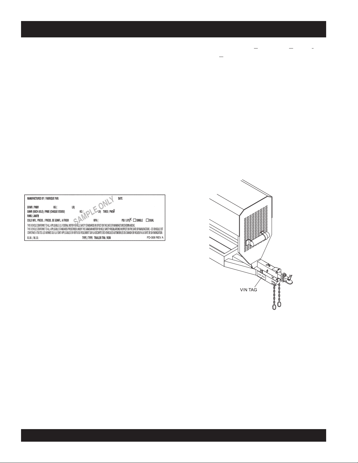
TRAILER SAFETY GUIDELINES
Some drivers place their hands at the bottom of the steering
wheel, and while the tow vehicle is in reverse, “think” of the
hands as being on the top of the wheel. When the hands
move to the right (counterclockwise, as you would do to
turn the tow vehicle to the left when moving forward), the
rear of the trailer moves to the right. Conversely, rotating
the steering wheel clockwise with your hands at the bottom
of the wheel will move the rear of the trailer to the left while
backing up.
If you are towing a bumper hitch rig, be careful not to allow
the trailer to turn too much because it will hit the rear of the
tow vehicle. To straighten the rig, either pull forward or turn
the steering wheel in the opposite direction.
Trailer VIN Tag
Figure 50 below is a sample of the Vehicle
Identification Number (VIN) Tag which is typically located
on the left front of the trailer. See Figure 51.
SAFETY WARNING LABELS ON YOUR TRAILER
PSIC: The tire pressure (Pounds per Square Inch)
measured when Cold.
VIN: The Vehicle Identification Number.
EMPTY WEIGHT: Some information that comes with the
trailer (such as the Manufacturer’s Statement of Origin) is
not a reliable source for “empty” or “net” weight. The shipping documents list average or standard weights and your
trailer may be equipped with options.
To determine the “empty” or “net” weight of your trailer, weigh
it on an axle scale. To find the weight of the trailer using an
axle scale, you must know the axle weights of your tow
vehicle without the trailer coupled. Some of the trailer
weight will be transferred from the trailer to the tow vehicle
axles, and an axle scale weighs all axles, including the tow
vehicle axles.
Figure 50. Vehicle VIN Tag
The trailer VIN Tag contains the following critical safety
information for the use of your trailer.
GAWR: The maximum gross weight that an axle can
support. It is the lowest of axle, wheel, or tire rating.
Usually, the tire or wheel rating is lower than the axle rating,
and determines GAWR.
GVWR: The maximum allowable gross weight of the trailer
and its contents. The gross weight of the trailer includes
the weight of the trailer and all of the items within it (such as
the pump, and other items). GVWR is sometimes referred
to as GTWR (Gross Trailer Weight Rating), or MGTW (Maximum Gross Trailer Weight). GVWR, GTWR and MGTW are
all the same rating.
The sum total of the GAWR for all trailer axles may be less
than the GVWR for the trailer, because some of the trailer
load is to be carried by the tow vehicle, rather than by the
trailer axle(s). The total weight of the cargo and trailer must
not exceed the GVWR, and the load on an axle must not
exceed its GAWR.
Figure 51. VIN Tag Location
PAGE 50 — MAYCO LS300 CONCRETE PUMP • OPERATION AND PARTS MANUAL — REV. #4 (06/21/10)
Page 51

TRAILER SAFETY GUIDELINES
Tow Vehicle
The towing hitch attached to your tow vehicle must have a
capacity equal to or greater than the load rating of the trailer
you intend to tow. The hitch capacity must also be matched
to the tow vehicle capacity. Your vehicle dealer can provide
and install the proper hitch on your tow vehicle.
Safety Chains
If the coupler connection comes loose, the safety chains
can keep the trailer attached to the tow vehicle. With
properly rigged safety chains, it is possible to keep the tongue
of the trailer from digging into the road pavement, even if
the coupler-to-hitch connection comes apart.
Suspension System
Sway bars, shock absorbers, heavy duty springs, heavy
duty tires and other suspension components may be required
to sufficiently tow the trailer and pump.
Brake Controller
For trailers equipped with electric brakes, the electric brake
controller is part of the tow vehicle and is essential in the
operation of the electric brakes on the trailer. The brake
controller is not the same as the safety breakaway brake
system that may be equipped on the trailer.
Trailer Lighting (and Braking) Connector
A device that connects electrical power from the tow vehicle to the trailer. Electricity is used to turn on brake lights,
running lights, and turn signals as required. In addition, if
your trailer has a separate braking system, the electrical
connector will also supply power to the brakes from the tow
vehicle.
Breakaway System
If the trailer coupler connection comes loose, the breakaway
system can actuate emergency electric or hydraulic brakes
Side View Mirrors
The size of the trailer that is being towed and your state law
regulations determine the size of the mirrors. However, some
states prohibit extended mirrors on a tow vehicle, except
depending on the type of actuator on the trailer. The
breakaway cable must be rigged to the tow vehicle with
appropriate slack that will activate the system if the coupler
connection comes loose.
while a trailer is actually being towed. In this situation, detachable extended mirrors are necessary. Check with your
dealer or the appropriate state agency for mirror requirements.
Jackstand
A device on the trailer that is used to raise and lower the
coupler. The jack is sometimes called the “landing gear” or
Heavy Duty Flasher
the “tongue jack”.
A Heavy Duty Flasher is an electrical component that may
be required when your trailer turn signal lights are attached
to the tow vehicle flasher circuit.
Electrical Connector
An Electrical Connector connects the light and brake
systems on the trailer to the light and brake controls on the
towing vehicle.
Emergency Flares and Emergency Triangle Reflectors
It is wise to carry these warning devices even if you are not
towing a trailer. It is particularly important to have these
when towing a trailer because the hazard flashers of your
towing vehicle will not operate for as long a period of time
when the battery is running both the trailer lights and tow
vehicle lights.
WARNING
An improperly coupled trailer can result in death or serious
injury.
DO NOT move the trailer until:
• The coupler is secured and locked to hitch;
• The safety chains are secured to the tow vehicle
• The trailer jack(s) are fully retracted.
DO NOT tow the trailer on the road until:
• Tires and wheels are checked;
• The trailer brakes are checked;
• The breakaway switch is connected to the tow vehicle;
• The load is secured to the trailer
• The trailer lights are connected and checked.
MAYCO LS300 CONCRETE PUMP • OPERATION AND PARTS MANUAL — REV. #4 (06/21/10) — PAGE 51
Page 52
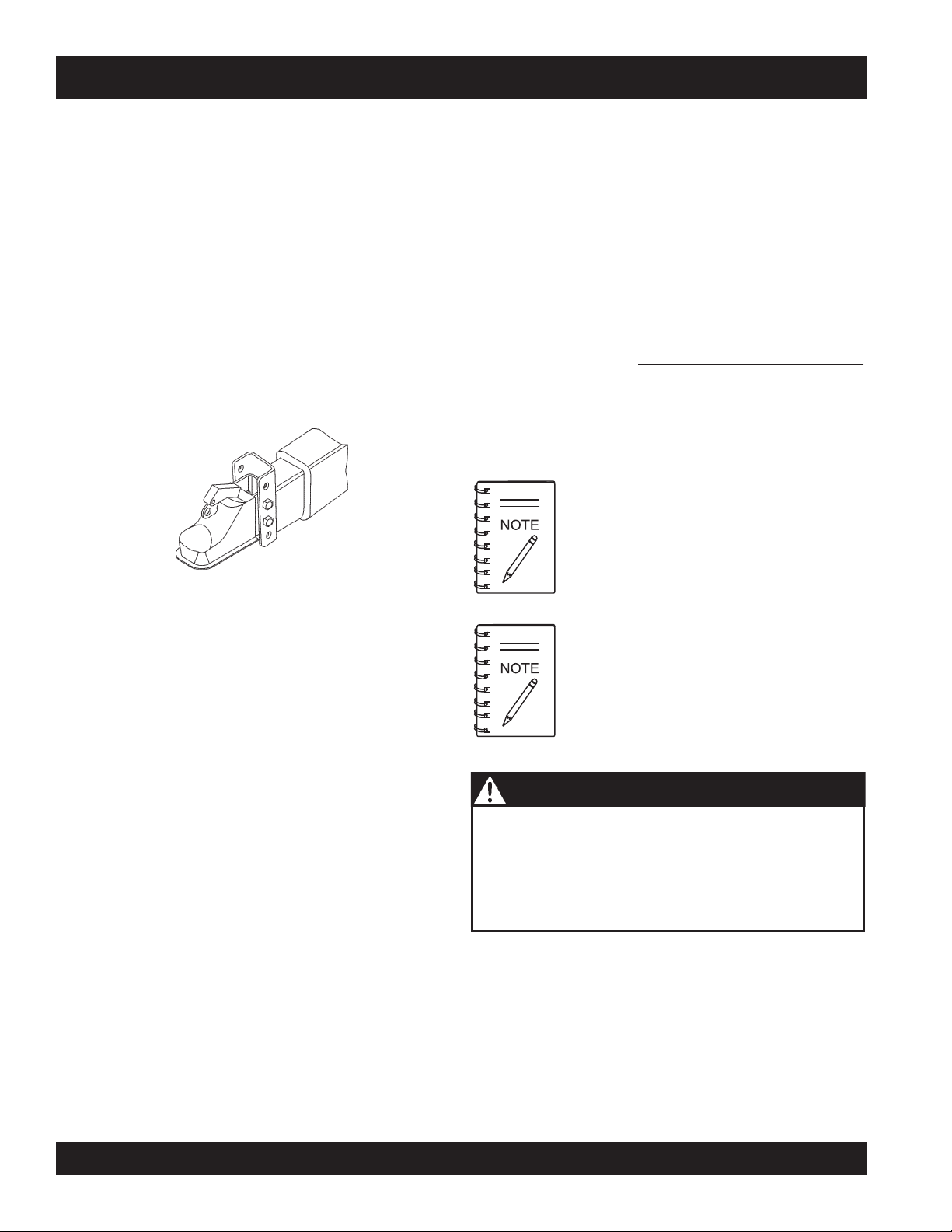
TRAILER SAFETY GUIDELINES
Coupler Types
The trailer is shipped from the factory with a 2-inch ball coupler.
The load rating of the coupler and the necessary ball size
are listed on the trailer tongue. You must provide a hitch
and ball for your tow vehicle where the load rating of the
hitch and ball is equal to or greater than that of your trailer.
Ball Hitch Coupler
A ball hitch coupler (Figure 52) connects to a ball that is
located on or under the rear bumper of tow vehicle. This
system of coupling a trailer to a tow vehicle is sometimes
referred to as “bumper pull.”
A ball hitch trailer may be fitted with a tongue jack that can
raise and lower the coupler. The tongue jack is mounted to
the A-frame (front, or tongue) part of the trailer. By rotating
the jack handle clockwise, the jack will extend and raise the
tongue of the trailer.
Also, the ball size must be the same as the coupler size. If
the hitch ball is too small, too large, is underrated, is loose
or is worn, the trailer can come loose from the tow vehicle
and may cause death or serious injury.
THE TOW VEHICLE, HITCH AND BALL MUST HAVE A
RATED TOWING CAPACITY EQUAL TO OR GREATER
THAN THE TRAILER Gross Vehicle Weight Rating
(GVWR). IT IS ESSENTIAL THAT THE HITCH BALL BE
OF THE SAME SIZE AS THE COUPLER.
The ball size and load rating (capacity) are marked on the
ball; hitch capacity is marked on the hitch.
When replacing a ball, the load rating
must match or exceed the GVWR of
the trailer.
Figure 52. Ball Hitch Coupler
Adjustable Tongue
Before each tow, coat the ball with a thin layer of automotive bearing grease to reduce wear and ensure proper operation. Check the locking device that secures the coupler to
the ball for proper operation.
If you see or feel evidence of wear, such as flat spots,
deformations, pitting or corrosion, on the ball or coupler,
immediately have your dealer inspect them to determine
the proper action to prevent possible failure of the ball and
coupler system. All bent or broken coupler parts must be
replaced before towing the trailer.
The coupler handle lever must be able to rotate freely and
automatically snap into the latched position. Oil the pivot
WARNING - Hitch Ball Load Rating
Coupler-to-hitch mismatch can result in uncoupling, leading to death
or serious injury.
Be sure the LOAD RATING of the hitch ball is equal or greater than
the load rating of the coupler.
Be sure the SIZE of the hitch ball matches the size of the ball coupler.
points, sliding surfaces, and spring ends with SAE 30W
motor oil. Keep the ball socket and latch mechanism clean.
Dirt or contamination can prevent proper operation of the
latching mechanism.
Before coupling the tow vehicle to the
trailer, be sure the size and rating of
hitch ball match the size and rating of
the coupler. Hitch balls and couplers
are marked with their size and rating.
PAGE 52 — MAYCO LS300 CONCRETE PUMP • OPERATION AND PARTS MANUAL — REV. #4 (06/21/10)
Page 53

WARNING - Defective Hitch Ball
2-INCH
TRAILER
COUPLER
2-INCH
BALL
TOW
VEHICLE
A worn, cracked or corroded hitch ball can fail while towing, and may
result in death or serious injury.
Before coupling trailer, inspect the hitch ball for wear, corrosion and
cracks.
Replace worn or damaged hitch ball.
WARNING - Uncoupled Hitch Ball
A
loose hitchball nut can result in uncoupling, leading to death or
serious injury.
Be sure the hitch ball is tight to the hitch before coupling the trailer.
Rock the ball to make sure it is tightened to the hitch,
and visually check that the hitch ball nut is solid against
the lock washer and hitch frame.
Wipe the inside and outside of the coupler. Clean and
visually inspect it for cracks and deformations. Feel the
inside of the coupler for worn spots and pits.
Be sure the coupler is secured tightly to the tongue of
the trailer. All coupler fasteners must be visibly solid
against the trailer frame.
The bottom surface of the coupler must be above the
top of the hitch ball. Use the tongue jackstand to support the trailer tongue. Wood or concrete blocks may
also be used.
TRAILER SAFETY GUIDELINES
Figure 53. Ball Hitch Coupling Mechanism
Lower the trailer (Figure 53) until the coupler fully engages the hitch ball.
Engage the coupler locking mechanism. In the engaged
position, the locking mechanism securely holds the
coupler to the hitch ball.
Insert a pin or lock through the hole in the locking
mechanism.
Be sure the coupler is all the way on the hitch ball and
the locking mechanism is engaged. A properly engaged
locking mechanism will allow the coupler to raise the
rear of the tow vehicle. Using the trailer jackstand, verify
that you can raise the rear of the tow vehicle by
1-inch after the coupler is locked to the hitch.
Lower the trailer so that its entire tongue weight is held
by the hitch.
Coupling the Trailer to the Tow Vehicle (Ball Coupler)
Lubricate the hitch ball and the inside of the coupler
with a thin layer of automotive bearing grease.
Slowly back up the tow vehicle so that the hitch ball is
near or aligned under the coupler.
Using the jackstand at the front of trailer (tongue), turn
the jackstand crank handle to raise the trailer. If the ball
coupler does not line up with the hitch ball, adjust the
position of the tow vehicle.
Open the coupler locking mechanism. Ball couplers have
a locking mechanism with an internal moving piece and
an outside handle. In the open position, the coupler is
able to drop fully onto the hitch ball.
MAYCO LS300 CONCRETE PUMP • OPERATION AND PARTS MANUAL — REV. #4 (06/21/10) — PAGE 53
Raise the jackstand to a height where it will not interfere
with the road.
Overloading can damage the tongue jack.
DO NOT use the tongue jack to raise the
tow vehicle more than 1 inch.
If the coupler cannot be secured to the hitch ball, do not
tow the trailer. Call your dealer for assistance. Lower the
trailer so that its entire tongue weight is held by the hitch
and continue retracting the jack to its fully retracted position.
Page 54
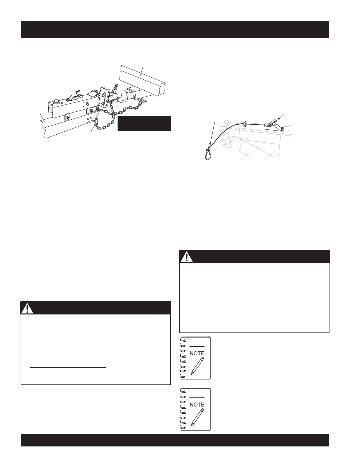
TRAILER SAFETY GUIDELINES
Attaching Safety Chain
TOW
VEHICLE
TRAILER
TONGUE
IMPORTANT!
SAFETY CHAIN
MASTER LINK
Figure 54. Safety Chain Arrangement
for a Bumper Pull Trailer (Ball Hitch)
Visually inspect the safety chains and hooks for wear
or damage. Replace worn or damaged safety chains
and hooks before towing.
Attach the safety chains so that they:
A. Cross underneath the coupler. See Figure 54.
B. Loop around a frame member of the tow vehicle
or holes provided in the hitch system (DO NOT
attach them to an interchangeable part of the hitch
assembly).
C. Have enough slack to permit tight turns, but not
be close to the road surface, so if the trailer un
couples, the safety chains can hold the tongue
up above the road.
WARNING - Safety Chains Rigging
Improper rigging of the safety chains can result in loss of
control of the trailer and tow vehicle, leading to death or
serious injury, if the trailer uncouples from the tow vehicle.
• Fasten chains to frame of tow vehicle. DO NOT fasten
chains to any part of the hitch unless the hitch has
holes or loops specifically for that purpose.
•
Cross chains underneath
enough slack to permit turning and to hold tongue up,
if the trailer comes loose.
CROSS BOTH
SAFETY CHAINS
hitch and coupler with
Breakaway Brake System
If the coupler or hitch fails, a properly connected and working breakaway brake system (Figure 55) will apply the hydraulic brakes on the trailer. The safety chains will keep the
tow vehicle attached and as the brakes are applied at the
trailer’s axles, the trailer/tow vehicle combination will come
to a controlled stop.
Connect Cable to
Tow Vehicle
Hydraulic Actuator
Breakaway Lever
Figure 55. Breakaway Brake System
Breakaway Cable Surge Brake System
The breakaway brake system includes a brake cable connected to the tow vehicle on one end and to the emergency
brake lever located on the hydraulic actuator on the other
end.
WARNING - Brakeaway Cable
An ineffective breakaway brake system can result in a
runaway trailer, leading to death or serious injury, if the
coupler or ball hitch fails.
Connect the breakaway cable to the tow vehicle; and NOT
to the hitch, ball or support.
Before towing the trailer, test the function of the breakaway
brake system. If the breakaway brake system is not
working, DO NOT tow the trailer. Have it serviced or
repaired.
DO NOT tow the trailer with the breakaway
brake system ON because the brakes will
overheat which can result in permanent
brake failure.
Replace the breakaway brake battery (if
equipped) at intervals specified by manufacturer.
PAGE 54 — MAYCO LS300 CONCRETE PUMP • OPERATION AND PARTS MANUAL — REV. #4 (06/21/10)
Page 55

TRAILER SAFETY GUIDELINES
Connecting Trailer Lights
TIRE SAFETY
Connect the trailer lights to the tow vehicle’s electrical
system using the electric connectors at the front of the trailer
(tongue). Refer to the wiring diagram shown in the trailer
wiring diagram section of this manual. Before towing the
trailer check for the following:
Running lights (turn on tow vehicle headlights).
Brake Lights (step on tow vehicle brake pedal).
Backup Lights (place tow vehicle gear shift in reverse).
Turn Signals (activate tow vehicle directional signal lever).
Unsafe Tires, Lug Nuts or Wheels
Trailer tires and wheels are more likely to fail than car tires
and wheels because they carry a heavier load. Therefore, it
is essential to inspect the trailer tires before each tow.
If a tire has a bald spot, bulge, cuts, is showing any cords,
or is cracked, replace the tire before towing. If a tire has
uneven tread wear, take the trailer to a dealer service center
for diagnosis.
Uneven tread wear can be caused by tire imbalance, axle
misalignment or incorrect inflation.
Tires with too little tread will not provide adequate tracking
WARNING - Improper Electrical Connections
Improper electrical connection between the tow vehicle
and the trailer will result in inoperable lights and electric
brakes, and can lead to collision.
Before each tow:
Check that the taillights, brake lights and turn signals
work
Check that the electric brakes work by operating the
brake controller inside the tow vehicle.
on wet roadways and can result in loss of control, leading to
death or serious injury.
Improper tire pressure causes an unstable trailer and can
result in a tire blowout and loss of control. Therefore, before
each tow you must also check the tire pressure. Tire
pressure must be checked when tires are cold.
Allow 3 hours cool-down after driving as much as 1 mile at
40 m.p.h. before checking tire pressure. NOTE: Trailer tires
Uncoupling the Ball Hitch
Follow these steps to uncouple ball hitch from tow vehicle:
Block trailer tires to prevent the trailer from rolling, before jacking the trailer up.
Disconnect the electrical connector.
will be inflated to higher pressures than passenger vehicle
tires.
Since trailer wheels and lug nuts (or bolts) are subjected to
greater side loads than automobile wheels, they are more
prone to loosen. Before each tow, check to make sure they
are tight.
Disconnect the breakaway brake switch cable. Promptly
replace the pullpin in the switchbox.
The proper tightness (torque) for lug nuts is listed in the lug
nut tightening section of this manual. Use a torque wrench
Before extending jackstand, make certain the ground
surface below the jackstand foot will support the tongue
load.
Rotate the jackstand handle (or crank) clockwise. This
to tighten the lug nuts. If you do not have a torque wrench,
use a lug wrench (from your tow vehicle) and tighten the
nuts as much as you can. Then have a service garage or
trailer dealer tighten the lug nuts to the proper torque.
will slowly extend the jack and transfer the weight of the
trailer tongue to the jack.
WARNING - Lug Nut Tightening
Metal creep between the wheel rim and lug nuts will cause
rim to loosen and could result in a wheel coming off,
leading to death or serious injury.
Tighten lug nuts before each tow.
MAYCO LS300 CONCRETE PUMP • OPERATION AND PARTS MANUAL — REV. #4 (06/21/10) — PAGE 55
Page 56
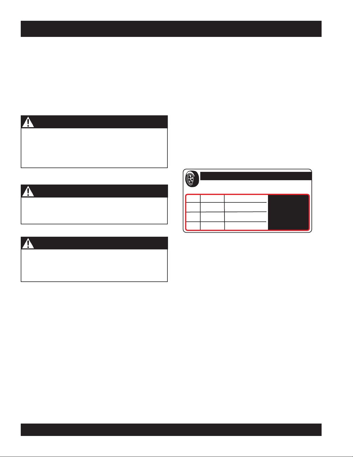
TRAILER SAFETY GUIDELINES
Lug nuts are also prone to loosen after first being assembled.
When driving a new trailer (or after wheels have been
remounted), check to make sure they are tight after the
first 10, 25 and 50 miles of driving and before each tow
thereafter.
Failure to perform this check can result in a wheel parting
from the trailer and a crash, leading to death or serious
injury.
Determining Load Limit of Trailer
Determining the load limits of a trailer includes more than
understanding the load limits of the tires alone. On all trailers there is a Federal certification/VIN label that is located
on the forward half of the left (road) side of the unit. This
certification/VIN label will indicate the trailer’s Gross Vehicle
Weight Rating (GVWR). This is the most weight the fully
loaded trailer can weigh. It will also provide the Gross Axle
Weight Rating (GAWR). This is the most a the axle can weigh.
WARNING - Lug Nut Loosening
Lug nuts are prone to loosen after initial installation, which
can lead to death or serious injury.
Check lug nuts for tightness on a new trailer or when
wheel(s) have been remounted after the first 10, 25 and
50 miles of driving.
WARNING - Improper Lug Nut Torque
Improper lug nut torque can cause a wheel parting from
the trailer, leading to death or serious injury.
Be sure lug nuts are tight before each tow.
There is a vehicle placard (Figure 56) located in the same
location as the certification label described above. This placard provides tire and loading information. In addition, this
placard will show a statement regarding maximum cargo
capacity.
The weight of cargo should never exceed XXX kg. Or XXX lbs
TIRE
FRONT
REAR
SPARE
TIRE AND LOADING INFORMATION
SIZE
COLD TIRE PRESSURE
SEE OWNER’S
MANUAL FOR
ADDITIONAL
INFORMATION
.
WARNING - Tire Pressure
Improper tire pressure can result in a blowout and loss of
control, which can lead to death or serious injury.
Be sure tires are inflated to pressure indicated on side
wall before towing trailer.
Figure 56. Tire and Loading Information Placard
If additional work items (hoses, tools, clamps etc.) are going to be added to the trailer, be sure they are distributed
evenly to prevent overloading front to back and side to side.
Heavy items should be placed low and as close to the axle
positions as reasonable. Too many items on one side may
overload a tire.
Excessive loads and/or underinflation cause tire
overloading and, as a result, abnormal tire flexing occurs.
This situation can generate an excessive amount of heat
within the tire. Excessive heat may lead to tire failure. It is
the air pressure that enables a tire to support the load, so
proper inflation is critical. The proper air pressure may be
found on the certification/VIN label and/or on the Tire
and Loading Information placard. This value should never
exceed the maximum cold inflation pressure stamped on
the tire.
PAGE 56 — MAYCO LS300 CONCRETE PUMP • OPERATION AND PARTS MANUAL — REV. #4 (06/21/10)
Page 57

TRAILER SAFETY GUIDELINES
Step 1.
Locate the statement, “The weight of cargo should never
exceed XXX kg or XXX lbs.,” on your vehicle’s
Tire and Loading Information placard (Figure 56). This figure
equals the available amount of equipment load capacity.
Step 2.
Determine the weight of the equipment being loaded on the
tow vehicle. That weight may not safely exceed the available equipment load capacity. The trailer’s Tire Information
Placard is attached adjacent to or near the trailer’s VIN (Certification) label at the left front of the trailer.
Determining Load Limit of Tow Vehicle
Step 1.
Locate the statement, “The combined weight of
occupants and cargo should never exceed XXX lbs.,” on
your vehicle’s placard.
Step 2.
Determine the combined weight of the driver and passengers who will be riding in your vehicle.
Step 3.
Subtract the combined weight of the driver and
passengers from XXX kilograms or XXX pounds.
Step 4.
The resulting figure equals the available amount of cargo and
luggage capacity. For example, if the “XXX” amount equals
1400 lbs. and there will be five 150 lb.
passengers in your vehicle, the amount of available cargo and
luggage capacity is 650 lbs. (1400-750 (5 x 150) = 650 lbs.).
Studies of tire safety show that maintaining proper tire
pressure, observing tire and vehicle load limits (not carrying
more weight in your vehicle than your tires or vehicle can
safely handle), avoiding road hazards and inspecting tires
for cuts, slashes and other irregularities are the most
important things you can do to avoid tire failure, such as
tread separation or blowout and flat tires. These actions,
along with other care and maintenance activities, can also:
Improve vehicle handling
Help protect you and others from avoidable breakdowns
and accidents.
Improve fuel economy
Increase the tire life
Use the information contained in this section to make tire
safety a regular part of your vehicle maintenance routine.
Recognize that the time you spend is minimal compared
with the inconvenience and safety consequences of a flat
tire or other tire failure.
Tire Fundamentals
Federal law requires tire manufacturers to place standardized information on the sidewall of all tires (Figure 57). This
information identifies and describes the fundamental characteristics of the tire and also provides a tire identification
number for safety standard certification and in case of a
recall.
Step 5.
Determine the combined weight of luggage and cargo being
loaded on the vehicle. That weight may not safely
exceed the available cargo and luggage capacity
calculated in Step 4.
If your vehicle will be towing a trailer, load from your trailer
will be transferred to your vehicle. Consult the tow vehicle’s
manual to determine how this weight transfer reduces the
available cargo and luggage capacity of your vehicle.
Figure 57. Standard Tire Sidewall Information
MAYCO LS300 CONCRETE PUMP • OPERATION AND PARTS MANUAL — REV. #4 (06/21/10) — PAGE 57
Page 58

TRAILER SAFETY GUIDELINES
P: The “P” indicates the tire is for passenger vehicles.
Next number: This three-digit number gives the width in
millimeters of the tire from sidewall edge to sidewall edge. In
general, the larger the number, the wider the tire.
U.S. DOT Tire Identification Number: This begins with
the letters “DOT” and indicates that the tire meets all federal
standards. The next two numbers or letters are the plant
code where it was manufactured, and the last four numbers
represent the week and year the tire was built. For example,
Next number: This two-digit number, known as the aspect
ratio, gives the tire’s ratio of height to width. Numbers of 70
or lower indicate a short sidewall for improved steering
response and better overall handling on dry pavement.
P: The “R” stands for radial. Radial ply construction of tires
has been the industry standard for the past 20 years.
Next number: This two-digit number is the wheel or rim
diameter in inches. If you change your wheel size, you will
have to purchase new tires to match the new wheel
diameter.
Next number: This two- or three-digit number is the tire’s
load index. It is a measurement of how much weight each
tire can support. You may find this information in your owner’s
manual. If not, contact a local tire dealer. Note: You may not
find this information on all tires because it is not required by
law.
M+S: The “M+S” or “M/S” indicates that the tire
the numbers 3197 means the 31st week of 1997. The other
numbers are marketing codes used at the manufacturer’s
discretion. This information is used to contact consumers
if a tire defect requires a recall.
Tire Ply Composition and Materials Used: The number
of plies indicates the number of layers of rubber-coated fabric in
the tire. In general, the greater the number of plies, the more
weight a tire can support. Tire manufacturers also must indicate
the materials in the tire, which include steel, nylon, polyester,
and others.
Maximum Load Rating: This number indicates the
maximum load in kilograms and pounds that can be carried
by the tire.
Maximum Permissible Inflation Pressure: This number
is the greatest amount of air pressure that should ever be
put in the tire under normal driving conditions.
Uniform Tire Quality Grading Standards (UTQGS)
has some mud and snow capability. Most radial tires have
these markings; hence, they have some mud and snow
capability.
Treadwear Number: This number indicates the tire’s wear
rate. The higher the treadwear number is, the longer it should
take for the tread to wear down. For example, a tire graded
Speed Rating: The speed rating denotes the speed at which
400 should last twice as long as a tire graded 200.
a tire is designed to be driven for extended periods of time.
The ratings range from 99 miles per hour (mph) to 186 mph.
These ratings are listed in Table 7. Note: You may not find
this information on all tires because it is not required by law.
Traction Letter: This letter indicates a tire’s ability to stop
on wet pavement. A higher graded tire should allow you to
stop your car on wet roads in a shorter distance than a tire
with a lower grade. Traction is graded from highest to lowest
as “AA”,”A”, “B”, and “C”.
gnitaRdeepS.6elbaT
gnitaRretteLgnitaRdeepS
Qhpm99
Rhpm601
Shpm211
Thpm811
Uhpm421
Hhpm031
Vhpm941
Whpm*861
Yhpm*681
Temperature Letter: This letter indicates a tire’s resistance
to heat. The temperature grade is for a tire that is inflated
properly and not overloaded. Excessive speed, underinflation
or excessive loading, either separately or in combination,
can cause heat build-up and possible tire failure. From highest
to lowest, a tire’s resistance to heat is graded as “A”, “B”, or
“C”.
PAGE 58 — MAYCO LS300 CONCRETE PUMP • OPERATION AND PARTS MANUAL — REV. #4 (06/21/10)
Page 59

TRAILER SAFETY GUIDELINES
Reference Figure 58 for additional tire information for light
trucks.
Make sure your tire valves have valve caps.
ALWAYS check tire pressure on tow vehicle and trailer
before towing. Check tire pressure at least once a month.
DO NOT overload tow vehicle. Check the tire
information and loading placard for safe allowable tire
loading conditions.
Tire Repair
The proper repair of a punctured tire requires a plug for the
hole and a patch for the area inside the tire that surrounds
the puncture hole. Punctures through the tread can be
repaired if they are not too large, but punctures to the sidewall
should not be repaired
rim to be properly inspected before being plugged and patched.
Figure 58. UTQGS Tire Information
Replacing Worn or Damaged Tires
Replace the tire before towing the trailer if the tire treads
Tires for light trucks have other markings besides those
found on the sidewalls of passenger tires.
LT: The “LT” indicates the tire is for light trucks or trailers.
ST: An “ST” is an indication the tire is for trailer use only.
Max. Load Dual kg (lbs) at kPa (psi) Cold: This informa-
tion indicates the maximum load and tire pressure when the
tire is used as a dual, that is, when four tires are put on each
rear axle (a total of six or more tires on the vehicle).
have less than 1/16 inch depth or the telltale bands are
visible. Check inflation pressure weekly during use to insure
the maximum tire life and tread wear. A bubble, cut or bulge
in a side wall can result in a tire blowout. Inspect both side
walls of each tire for any bubble, cut or bulge; and replace a
damaged tire before towing the trailer.
Table 8 below will help pinpoint the causes and solutions of
tire wear problems.
. Tires must be removed from the
Max. Load Single kg (lbs) at kPa (psi) Cold
This information indicates the maximum load and tire
pressure when the tire is used as a single.
TABLE 7 TIRE WEAR TROUBLESHOOTING
WEAR PATTERN SOLUTION
Load Range
This information identifies the tire’s load-carrying capabilities and its inflation limits.
Tire Safety Tips
Slow down if you have to go over a pothole or other
object in the road.
DO NOT run over curbs or other foreign objects in the
roadway, and try not to strike the curb when parking.
Check tire inflation pressure weekly during use to insure the maximum tire life and tread wear.
DO NOT bleed air from tires when they are hot.
Inspect tires for uneven wear patterns on the tread,
cracks, foreign objects, or other signs of wear or trauma.
Remove bits of glass and foreign objects wedged in the
tread.
CAUSE
Center Wear
Edge Wear Under Inflation
Side Wear
Toe Wear
Cupping
Flat Spots
Over Inflation
Loss of chamber
or overloading.
Incorrect toe-in
Out-of balance
Wheel lockup &
tire skidding.
Adjust pressure to
particular load per
tire manufacturer.
Adjust pressure to
particular load per
tire manufacturer.
Make sure load does
not exceed axle rating.
Align wheels.
Align wheels.
Check bearing adjustment and balance tires.
Avoid sudden stops
when possible and
adjust brakes.
MAYCO LS300 CONCRETE PUMP • OPERATION AND PARTS MANUAL — REV. #4 (06/21/10) — PAGE 59
Page 60

TRAILER SAFETY GUIDELINES
WARNING - Flying Objects
Lug Nut Torque Requirements
It is extremely important to apply and maintain proper wheel
ALWAYS
removing or installing force fitted parts
DO NOT attempt to repair or modify a
wear safety glasses when
mounting torque on the trailer. Be sure to use only the fasteners matched to the cone angle of the wheel. Proper procedure for attachment of the wheels is as follows:
wheel. DO NOT install an inner-tube to
correct a leak through the rim. If the rim
is cracked, the air pressure in the inner tube may cause
pieces of the rim to explode (break off) with great force
and cause serious eye or bodily injury.
1. Start all wheel lug nuts by hand.
2. Torque all lug nuts in sequence. See Figure 59. DO NOT
torque the wheel lug nuts all the way down. Tighten each
lug nut in 3 separate passes as defined by Table 9.
3. Check to see if the lug nuts are tight after the first 10, 25
Wheel Rims
and 50 miles of driving and before each tow thereafter.
If the trailer has been struck, or impacted, on or near the
wheels, or if the trailer has struck a curb, inspect the rims for
damage (i.e. being out of round); and replace any damaged
wheel. Inspect the wheels for damage every year, even if no
obvious impact has occurred.
Wheels, Bearings and Lug Nuts
A loose, worn or damaged wheel bearing is the most
common cause of brakes that grab.
eziSleehW
"2152-0204-5356-05
"3152-0204-5356-05
"4152-0206-05021-09
ssaPtsriF
SBL-TF
ssaPdnoceS
SBL-TF
STNEMERIUQEREUQROTERIT.8ELBAT
ssaPdrihT
SBL-TF
To check wheel bearings, jack trailer and check wheels for
side-to-side looseness. If the wheels are loose, or spin with
a wobble, the bearings must be serviced or replaced. Check
inflation pressure weekly during use to insure the maximum
tire life and tread wear. Most trailer axles are built with sealed
bearings that are not serviceable. Sealed bearings must be
replaced as complete units.
NEVER! use an pneumatic air gun
to tighten wheel lug nuts.
WARNING - Lug Nut Tightening
Over-tightening lug nuts will result in breaking the studs
or permanently deforming the mounting stud holes in the
wheels.
WARNING - Lug Nut Inspection
"5152-0206-05021-09
"6152-0206-05021-09
Lug nuts are prone to loosen after initial installation, which
can lead to death or serious injury. Check all wheel lug
nuts periodically.
Figure 59. Wheel Lug Nuts Tightening Sequence
PAGE 60 — MAYCO LS300 CONCRETE PUMP • OPERATION AND PARTS MANUAL — REV. #4 (06/21/10)
Page 61

TRAILER SAFETY GUIDELINES
Figure 60. Trailer to Tow Vehicle Wiring Diagram
Lights and Signals
Before each tow, check the trailer taillights, stoplights, turn
signals and any clearance lights for proper operation.
Replace any broken or burned-out lamps as necessary.
Check the wire harness for cuts, fraying or other damage. If
it needs replacing, contact your dealer.
MAYCO LS300 CONCRETE PUMP • OPERATION AND PARTS MANUAL — REV. #4 (06/21/10) — PAGE 61
WARNING - Trailer Lights
Improper operating taillights, stoplights and turn signals
can cause collisions.
Check all lights before each tow.
Page 62

TROUBLESHOOTING (PUMP)
The hydraulic troubleshooting procedures listed below are intended for use by individuals equipped with the proper tools and
equipment and are familiar with hydraulic systems and safe shop practices. Use the Pump Troubleshooting Table (Table 8) to
identify possible causes for the pump’s malfunction. Contact the Multiquip Service department for the proper repair procedure.
DANGER - AMPUTATION RISK
You will be required to put your hand in the concrete
cylinders or near the shuttle tube. You are at
EXTREME RISK
engine is running or if pressure is in the hydraulic
system.
Prior to performing any maintenance on the pump, stop
the engine by turning off the ignition switch and remove
the starter key. Place a “DO NOT OPERATE” tag
over the switch and disconnect the battery. The
pressure reading on the accumulator pressure gauge
MUST
read ZERO. ALWAYS relieve the accumulator
circuit to zero pressure
prior to performing any
maintenance on the
pump.
of injury or
AMPUTATION
if the
DO NOT open hydraulic lines or loosen hydraulic fittings
while the engine is running! Hydraulic fluid under pressure
can penetrate the skin, blind, cause burns or create other
potentially dangerous hazards.
WARNING - HYDRAULIC SYSTEM HAZARD
GNITOOHSELBUORTPMUP.9ELBAT
melborPmelborPelbissoPtoohselbuorToT
upehtkcehc,hctiwsgoJehtgnisU
gnitarepOmetsyStcerrocnI
erusserP
gnittesMPRenignEtcerrocnI
ISP05-/+0013
0552ottes
lliwrednilyCciluardyHniaM
elcycton
ixorP
eruliaFhctiwSytim
evlaVfeileRniaMdetanimatnoC
srednilyClairetaMdetcurtsbO
ileR
evlaVfe
srednilycehtedisni
lacirtcelErof21elbaTotrefeR
gnitoohselbuorT
pm
.xorppasitiyfireV.eguagerusserp
psMPRhgihs'enigneehtyfireV
sidee
detanimatnocarofdlofinamehtkcehC
)lairetamdeird(snoitcurtsborofkcehc
PAGE 62 — MAYCO LS300 CONCRETE PUMP • OPERATION AND PARTS MANUAL — REV. #4 (06/21/10)
Page 63

TROUBLESHOOTING (PUMP)
)DEUNITNOC(GNITOOHSELBUORTPMUP.9ELBAT
?evlaVfeileRdetanimatnoC
gregnetondioneloSgniwS
?gnizi
seodrednilyCelttuhS
ekortston
?ylreporpgninoitcnuftonevlaVgniwS
gnitoohselbuorTlacirtcelEotrefeR
oA)21elbaT(
ciluardyHniaMtcerrocnI
otwolsrednilyCelttuhS
ekortsetelpmoc
uorTlacirtcelEotrefeR
sdioneloSgniwSBr
?gnittesMPRenignEtcerrocnI
?erusserPgnitarepOmetsyS
?egdirtraCfeileRdetanimiatnoC
gnitoohselb
eV
DdnaCsehctiwSytimixorP)21elbaT(
evlaVfeileR
egatlovlangisV21
hctiwsgniggojrednilyclaunam
0552ottes
xorppasiti
ISP05-/+0013.
egdirtraCfeileRgniwS
detanimatnocarofdlofinamehtkcehC
dnadionelostuodenrubrofkcehC
tgnisupmupehtelcycyllaunaM
eh
sideepsMPRhgihs'enigneehtyfir
yfireV.egagerusserppmupehtkcehC
detanimatnocrofdlofinamehtkcehC
laeSelppiNegrahcsiDreppoH
?detacirbulylreporpmi
evissecxegnitaercreppohdengila-siM
ppinteltuoehtnonoitcirf
?eveels
atlovyrettaB
.tratsotton
sllafeg
rettabdaeD yrettabehtnoegrahcehtkcehC
)gninnur(CDV21woleb
/gnitrats(CDV5.9ro
latigidno)gniknarc
enignegnisuac,yalpsid
?y
gniraebel
teltuo
?xoBlortnoCedisninoitcennocgniriW
elp
piNegrahcsiDreppoHehtkcehC
tnacirbulfokcaldnagnizeisroflaeS
siebutSgnirusnereppohngilaeR
reppohehtforetnecehtnignitator
dnasnoitcennocgniriwehtkcehC
wsnoitingignihcaersirewopyfirev
hcti
MAYCO LS300 CONCRETE PUMP • OPERATION AND PARTS MANUAL — REV. #4 (06/21/10) — PAGE 63
Page 64

TROUBLESHOOTING (ENGINE)
Practically all breakdowns can be prevented by proper handling and maintenance inspections, but in the event of a
breakdown, please take a remedial action following the diagnosis based on the Engine Troubleshooting (Table 10) information
shown below and on the proceeding page. If the problem cannot be remedied, please leave the unit just as it is and consult
our company's business office or service plant.
GNITOOHSELBUORTENIGNE.01ELBAT
MOTPMYSMELBORPELBISSOPNOITULOS
"POTS"nisirevellortnocdeepS .noitisop"TRATS"otrevellortnocdeepsteS
noitisop
pmupnoitcejnignihcaerleufoN .metsysle
pmupleufevitcefeD.pmupleufecalpeR
deggolcretlifleuF .knatnaelcdnaretlifleufecalpeR
nilylppusleufytluaF .enilleufriaperroecalpeR
sitratsrotratstonlliwenignE
ebnacenignehguohtla,deyaled
.revodenrut
enigneserutarepmetwoltA
.tratstonlliw
noosspotstubserifenignE
sa
.ffodehctiwssiretrats
e
wolootnoisserpmoC
yltcerrocgnikrowtonrotcejnileuF
wolooterusserpliO .erusserplioenignekcehC
dedeecxetimilerutarepmetgnitratswoL
sahsetarapesleuF
serutarepmetwol
kcihtootlioenignE
noitisopPOTSnirevelelttorhT .noitisopNURotrevelelttorhtnoitisopeR
dekcolbretlifleuF.retlifleufecalpeR
dekcolbylppusleuF .metsysleuferitneehtkcehC
otecnatsiseretauqedani
mriaperenigne
morf
.leuf
uferitnekcehC.leufddA
rotsujdA.sevlavdnarednilyc,notsipkcehC
unamriaperenignerepriaper
.la
htiwecnadroccanirotcejniecalperroriapeR
.launa
nignitratsdlochtiwylpmoC
.ytisocsivlioreporp
eR.metsysylppus
.tnemnorivneretniwrof
dnasnoitcurts
segremeleuf)dibrutton(raelcrehtehwkcehC
noitcejnimorfhcated(enilleufeht
mraw,detarapesrodibrutsileufehtfI.)pmup
leufetelpmocehtniardroenigneehtpu
leseidedargretniwhtiwleuf
liofoepyttcerrochtiwesacknarcenignellifeR
senignE
.noitarepolamron
.deeps
ps
gnirudflestiybspot
dnatuptuo,rewopenignewoL
woldnatuptuorewopenignewoL
.ekomstsuahxekcalb,dee
ytpmeknatleuF.leufddA
dekcolbretlifleuF.retlifleufecalpeR
ytpmeknatleuF.retlifleufecalpeR
deggolcretlifleuF.retlifleufecalpeR
etauqedanisignitnevknatleuF .det
niniamertonseodrevellortnocdeepS
noitisopdetceles
llufootlevellioenignE?levellioenignetcerroC
dekcolbretlifriA .retlifriaecalperronaelC
secnaraelcevlavtcerrocnI .noitacificepsenignerepsevlavtsujdA
rotcejnitanoitcnuflaM.launamenigneeeS
nevyletauqedasiknattahterusnE
amenigneeeS
PAGE 64 — MAYCO LS300 CONCRETE PUMP • OPERATION AND PARTS MANUAL — REV. #4 (06/21/10)
.noitcaevitcerrocroflaun
Page 65

TROUBLESHOOTING (TRAILER BRAKE SYSTEM)
Practically all breakdowns can be prevented by proper handling and maintenance inspections, but in the event of a
breakdown, please take a remedial action following the diagnosis based on the Brake System Troubleshooting
(Table 10) information shown below and on the proceeding page. If the problem cannot be remedied, please leave the unit
just as it is and consult our company's business office or service plant.
GNITOOHSELBUORTMETSYSEKARB.11ELBAT
MOTPMYS MELBORPELBISSOP NOITULOS
gniraebleehwdetaehrevO .esaerghtiwkcapdnagniraebleehwecalpeR
diulfekarbwoL .metsysekarbdeelbdnalliF
.kcuhcrorettahc,kaeuqssekarB
rednilycretsamrotatucadezeiS .rednilycretsamdliubeR/ecalpeR
esioneohsekarB .yrassecenfiecalperroseohstsujdA.smurdtcepsnI
rednilycleehwgnikaeL .metsysekarbdeelbdnarednilycleehwecalperdnakcehC
leveldiulfekarbwoL .metsysekarbdeelbdnadiulfekarbdevorppatodhtiwlliF
egamademarfrotautcaekarB .tinurotautcaetelpmocecalpeR
dehcnipgniebenilekarB .enilekarbecalpeR
,etarepootliaf,haehrevosekarB
ylroopnoitcnufro,edisehtotllup
rotautcadezieS .rotautcadliuberroecalpeR
gnirpsnruternekorB .gnirpsecalpeR
detsujdaylreporpmisekarB .tnemtsujdakcehC
metsyselbacyawa-kaerB
detavitcayllaitrap
yrP.tcerrocdnaesuacenimreteD.dellupebthgimelbacyawa-kaerB
ilitnuelbacnopu
gnirpselbactsniagastserrosehcuotdaebrotacidn
.gardtneverpdnasekarbemarfehtesaelerylluflliwsihT.pots
MAYCO LS300 CONCRETE PUMP • OPERATION AND PARTS MANUAL — REV. #4 (06/21/10) — PAGE 65
Page 66

TROUBLESHOOTING (ELECTRICAL)
Refer to Figure 61 for the location of components for troubleshooting.
NOITCNUFLAM
GNIDAER
(
1neercS
)
ESUACELBABORP NOITULOS
GNITOOHSELBUORTLACIRTCELE.21ELBAT
(ciluardyhniaM
(ciluardyhniaM
(ciluardyhniaM
NIAMNEPOA
.dionelosgnilcycV21tnruB
ciluardyhniaM(
)dekcolsrednilyc
.nekorbnoitcennoceriW .eriwnekorbecalpeR
DETROHSANIAM
)dekcolsrednilyc
NEPOBNIAM
)dekcolsrednilyc
DETROHSBNIAM
)dekcolsrednilyc
NEPOAGNIWS
ELTTUHS
REDNILYC
DETCARTER
.dnuorg
.dionelosgnilcycV21tnruB
.nekorbnoitcennoceriW .eriwnekorbecalpeR
.dnuorg
.dionelosgnilcycV21tnruB
.nekorbnoitcennoceriW .eriwnekorbecalpeR
otyltceriddetrohssidionelosgnilcyctlov-21ehT
.dnuorgehtotyltceriddetrohssinoitcennoceriW .noitcennoctcerroC
otyltceriddetrohssidionelosgnilcyctlov-21ehT
.dnuorgehtotyltceriddetrohssinoitcennoceriW .noitcennoctcerroC
.evlavecalpeR.smho6daer
.evlavecalpeR.smho6daer
.evlavecalpeR.smho6daer
.evlavecalpeR.smho6daer
.evlavecalpeR.smho6daer
dluohstI.ecnatsiserliocdioneloserusaeM
dluohstI.ecnatsiserliocdioneloserusaeM
dluohstI.ecnatsiserliocdioneloserusaeM
dluohstI.ecnatsiserliocdioneloserusaeM
dluohstI.ecnatsiserliocdioneloserusaeM
AGNIWS
DETROHS
ELTTUHS
REDNILYC
DETCARTER
NEPOBGNIWS
ELTTUHS
REDNILYC
DEDNETXE
AGNIWS
DETROHS
ELTTUHS
REDNILYC
DEDNETXE
.dnuorg
.dionelosgnilcycV21tnruB
.nekorbnoitcennoceriW .eriwnekorbecalpeR
.dnuorg
otyltceriddetrohssidionelosgnilcyctlov-21ehT
.dnuorgehtotyltceriddetrohssinoitcennoceriW .noitcennoctcerroC
otyltceriddetrohssidionelosgnilcyctlov-21ehT
.dnuorgehtotyltceriddetrohssinoitcennoceriW .noitcennoctcerroC
dluohstI.ecnatsiserliocdioneloserusaeM
.evlavecalpeR.smho6daer
dluohstI.ecnatsiserliocdioneloserusaeM
.evlavecalpeR.smho6daer
dluohstI.ecnatsiserliocdioneloserusaeM
.evlavecalpeR.smho6daer
PAGE 66 — MAYCO LS300 CONCRETE PUMP • OPERATION AND PARTS MANUAL — REV. #4 (06/21/10)
Page 67

TROUBLESHOOTING (ELECTRICAL)
)deunitnoc(GNITOOHSELBUORTLACIRTCELE.21ELBAT
NOITCNUFLAM
GNIDAER
(
1neercS
)
ESUACELBABORP NOITULOS
.langisgnidnestonxoBlortnoClatigiD .sutatslanoitareporof5#neercskcehC
CHCTIWSYTIMIXORP
.rosnesytimixorp
.langisgnidnestonxoBlortnoClatigiD .sutatslanoitareporof5#neercskcehC
DHCTIWSYTIMIXORP
.rosnesytimixorp
.dionelostlov-21tnruB .dionelostnrubecalpeR
NEPODIONELOSLEUF
.nekorbnoitcennoceriW .eriwnekorbecalpeR
otyltceriddetrohssidionelostlov-21ehT
DIONELOSLEUF
DETROHS
TNALOOC
ERUTAREPMET
.dnuorg
ehtotyltceriddetrohssinoitcennoceriW
.dnuorg
.gnitaehrevoenignE .gnitoohselbuorTenignEotrefeR
.gnizigrenetonhctiwS
■
gnizigrenetongnikortstrohsrednilycelttuhS
■
■
■
gnizigrenetongnikortstrohsrednilycelttuhS
■
■
)mm156.1(
reppohdengila-siM
gnizieselppinegrahcsiD
noitacirbulseriuqerteltuoreppoH
reppohdengila-siM
gnizieselppinegrahcsiD
noitacirbulseriuqerteltuoreppoH
.dionelosdetrohsecalpeR
.noitcennoctcerroC
ebdluohS.ecnaraelctcatnocrofkcehC
.ni560.0dna)mm72.1(.ni050.0neewteb
AHCTIWSYTIMIXORP
BHCTIWSYTIMIXORP
ERULIAFROTANRETLA
.hctiwsytimixorpevitcefeD .hctiwsecalpeR
.nekorbnoitcennoceriW .eriwnekorbecalpeR
.dnuorgotdetrohsyltceridsinoitcennoceriW .noitcennoctcerroC
.gnizigrenetonhctiwS .ecnaraelctcatnocreporpmI
.hctiwsytimixorpevitcefeD .hctiwsecalpeR
.nekorbnoitcennoceriW .eriwnekorbecalpeR
.dnuorgotdetrohsyltceridsinoitcennoceriW .noitcennoctcerroC
.rotanretlaevitcefeD tleb-VkcehC.rotanretlaecalpeR
nekorbsitleb-VnafgniloocrewolbenignE
.tnemecalpergniriuqer
.tleb-VecalpeR
MAYCO LS300 CONCRETE PUMP • OPERATION AND PARTS MANUAL — REV. #4 (06/21/10) — PAGE 67
Page 68
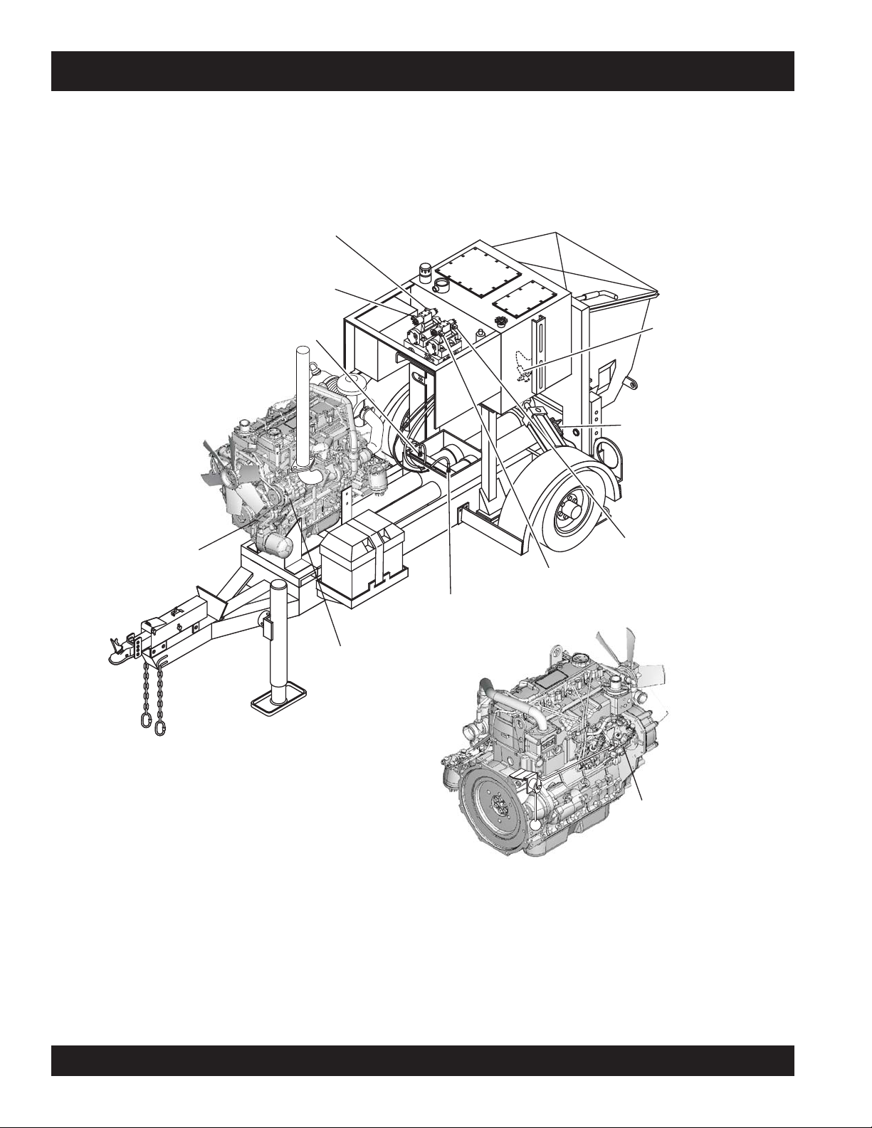
E
F
P1
B1
P2
T2
A1
T1
MAIN “A”
SOLENOID
MAIN “B”
SOLENOID
TROUBLESHOOTING (ELECTRICAL)
V-BELT
PROXIMITY
SWITCH “A”
ALTERNATOR
PROXIMITY
P
1
B
1
T
1
P
A
2
1
T
2
SWITCH “D”
PROXIMITY
SWITCH “C”
SWING “A”
SOLENOID
PROXIMITY
SWITCH “B”
SWING “B”
SOLENOID
INTERNAL
FUEL
SOLENOID
Figure 61. Location of Components for Electrical Troubleshooting
PAGE 68 — MAYCO LS300 CONCRETE PUMP • OPERATION AND PARTS MANUAL — REV. #4 (06/21/10)
Page 69

WIRING DIAGRAM (CONTROL BOX)
TBD
Figure 62. Connections to Digital Control Box - J1 and J2 Connectors ( 1 of 2)
MAYCO LS300 CONCRETE PUMP • OPERATION AND PARTS MANUAL — REV. #4 (06/21/10) — PAGE 69
Page 70

WIRING DIAGRAM (CONTROL BOX)
TBD
Figure 62. Connections to Digital Control Box - J1 and J2 Connectors ( 2 of 2)
PAGE 70 — MAYCO LS300 CONCRETE PUMP • OPERATION AND PARTS MANUAL — REV. #4 (06/21/10)
Page 71

WIRING DIAGRAM (CONTROL BOX)
TBD
Figure 63. Connections to Digital Control Box - J3 and J4 Connectors ( 1 of 2)
MAYCO LS300 CONCRETE PUMP • OPERATION AND PARTS MANUAL — REV. #4 (06/21/10) — PAGE 71
Page 72

WIRING DIAGRAM (CONTROL BOX)
TBD
Figure 63. Connections to Digital Control Box - J3 and J4 Connectors ( 2 of 2)
PAGE 72 — MAYCO LS300 CONCRETE PUMP • OPERATION AND PARTS MANUAL — REV. #4 (06/21/10)
Page 73

WIRING DIAGRAM (DIGITAL READOUT SCREEN)
BROWN (DECREASE)
GREEN (INCREASE)
RED (IGNITION +12VDC)
BLUE (UNLOADER SOLENOID)
RED (FUEL SOLENOID)
RED/BLACK
J4
12
T0 J1-7
(RED)
T0 J4-7
(BLK)
NC
NC
NC
1
1
222
DIGITAL READOUT
E-STOP
34 56 78
1
MODULE
BLACK
RED
ORANGE
GRAY
+12VDC IN
+12VDC OUT
34 56 78
12
GND
J1
1
2
3
4
5
6
7
8
J2J3
BROWN
PURPLE
2
RESET/SET
VOLUME
12 3
(-)
1
3
BLACK
RED
WHITE
BLUE
YELLOW
GREEN
BROWN
ORANGE
CONTROLLER
BLACK POTTED
RED
1
2
3
SCROLL
(+)
BOX
WHITE
BLACK
RADIO
REMOTE
CONTROL
CONNECTOR
RED
FLOW
DIRECTION
TO J3-7
RED/
BLK
TO J4-5
RED
1
(LOCAL)
CONTROL
2
3
(REMOTE)
GRN
YELLOW (REV)
BLUE
(FWD)
WHITE
RED
TO J1-1
(30)
(15/54)
IGNITION
SWITCH
TO J1-3
(50A)
BLACK
BLUE
(JOG A)
GRN/YEL
12 3
CYLINDER
STROKE
BLK
(JOG B)
ORANGE
RED
AUTOMATIC/JOG
WHITE
12 3
REMOTE
Figure 64. Connections to Digital Readout Screen
MAYCO LS300 CONCRETE PUMP • OPERATION AND PARTS MANUAL — REV. #4 (06/21/10) — PAGE 73
Page 74

WIRING DIAGRAM (HOPPER VIBRATOR)
Figure 65. Optional Hopper Vibrator Wiring Diagram
PAGE 74 — MAYCO LS300 CONCRETE PUMP • OPERATION AND PARTS MANUAL — REV. #4 (06/21/10)
Page 75

HYDRAULIC SYSTEM DIAGRAM
Figure 66. Hydraulic System Diagram
MAYCO LS300 CONCRETE PUMP • OPERATION AND PARTS MANUAL — REV. #4 (06/21/10) — PAGE 75
Page 76

MANIFOLD BLOCK PORTS
STROPKCOLBDLOFINAM
CCAknaTrotalumuccAottcennoC
1ArednilyCciluardyHottcennoC
2ArednilyCelttuhSottcennoC
1BrednilyCciluardyHottce
nnoC
2BrednilyCelttuhSottcennoC
1PevlaVlortnoCwolFottcennoC
2PpmuPciluardyHottcennoC
1TregnahcxEtaeHottcennoC
2TknaTciluardyHottcennoC
P1
T1
T1
T1
A1
P1
A1
P1
A1
T2
B1
T2
ACC
B1
T2
P2
B2
A2
P2
B1
P2
Figure 67. Manifold Block Ports
PAGE 76 — MAYCO LS300 CONCRETE PUMP • OPERATION AND PARTS MANUAL — REV. #4 (06/21/10)
Page 77

APPENDIX — CONCRETE MIX INFORMATION
The following information has been extracted from actual testing laboratory reports. The purpose of this printing is only to
help create a better understanding of the importance of uniform gradation and proportioning of materials which affect
pumpability of concrete mixes. These weights and proportions illustrate that when the sieve analysis is ideal, the sand/rock
ratio can be adjusted (65% sand 35% rock) and pumpability should be excellent.
EXAMPLE #1 (A California Test Lab. Report)
JOB: Building Foundations (Water Project)
Sacks per cu./yd. 6.5 designed for 2,500 lbs. in 28 days
Gallons per sack 7.1
Washed Sand-#200 wash 1.3
Organic matter-OK
Specific gravity (SSD) Sand-2.58; Pea Gravel-2.60
Sieve analysis-percent passing
Material 1.5” 1” 3/4” 3/8” #4 #8 #16 #30 #50 #100 #200
W.C. Sand 100 99.7 79.1 60.4 36.5 14.3 4.0 1.1
Pea Gravel 100 3.0
% Comb. 100 66 51 39 23 9 3 1.0
DESIGN FOR ONE YARD OF CONCRETE (SATURATED & SURFACE DRY):
Absolute volume of aggregate in one cu. yard: 17.78 cu. ft.
Specific gravity of aggregates in one cu. yard: 2.58
Weight of aggregates in one cu. yard batch: 2850 lbs.
% BATCH SPEC. GRAVITY ABS. VOL.
W.C. Sand 65 1800 2.58 11.56
PEA GRAVEL 35 1000 2.60 6.22
WATER 46 gal. 1
CEMENT 6.5 sk. 611
TOTAL 27.00
ADMIXTURE: None
SLUMP 4”
REMARKS This mix designed for pumping
NOTE: Due to the availability of well-graded sand as shown in the above sieve analysis,
this mix pumped very successfully.
MAYCO LS300 CONCRETE PUMP • OPERATION AND PARTS MANUAL — REV. #4 (06/21/10) — PAGE 77
Page 78

APPENDIX — CONCRETE MIX INFORMATION
A.S.T.M. STANDARD SPECIFICATION FOR GRADING AGGREGATE
PAGE 78 — MAYCO LS300 CONCRETE PUMP • OPERATION AND PARTS MANUAL — REV. #4 (06/21/10)
Page 79

APPENDIX — SLUMP TEST PROCEDURE
1. To obtain a representative sample (concrete), take
5. Fill cone to overflowing
several samples at three or more regular intervals
throughout the discharge of the mixer or truck. DO
NOT take samples at the beginning or end of the
discharge.
2. Dampen the inside of the cone and place it on a
smooth, moist, nonabsorbent, level surface large
enough to accommodate both the slumped concrete
and the slump cone. Stand on the “foot pieces”
throughout the test procedure to hold the cone firmly
in place.
6. Remove the excess concrete
3. Fill the cone 1/3 full by volume (Figure 68-A) and rod
25 times with a 1/2” dia x 24” lg. bullet-pointed steel
rod. (This is a specific requirement which will produce
non-standard results unless followed exactly.) Distribute rodding evenly over the entire cross section of
(Removing Excess Concrete)
the sample.
BULLET POINTED
STEEL ROD
(Figure68-C). Rod this layer 25
times with rod penetrating into
but not through, the second
layer. Distribute rodding evenly
over the entire cross section of
this layer.
Figure 68-C. Slump Test
(Full-Overflow)
(Figure 68-D) from the top of
the cone, using the tamping
rod as a screed.
Figure 68-D. Slump Test
FULL
(OVERFLOW)
7. Lift the cone vertically
(Figure 68-E) with a slow even
motion. DO NOT jar the concrete or tilt the cone during this
1/3 FULL
1/2 DIAMETER
24 INCHES LONG
FOOT
PIECE
Figure 68-A. Slump Test (1/3 Full)
4. Fill cone another 1/3 (Figure 68-B) which will make the
cone 2/3 full by volume. Rod this second layer 25 times
process. ( Invert the withdrawn
cone, and place it next to, but
not touching the slumped concrete.
Figure 68-E. Slump Test
with the rod penetrating into, but not through, the first
layer. Distribute rodding evenly over the entire cross
section of the layer.
8. Lay a straight edge (Figure 68-F) across the top of the
slumped cone. Measure the amount of slump in inches
from the bottom of the straight
edge to the top of the slumped
concrete at a point over the
original center of the base . The
slump operation must be complete in a maximum elapsed
2/3 FULL
time of 1-½ minutes. Discard
the concrete. DO NOT use it in
another tests.
Figure 68-B. Slump Test (2/3 Full)
(Cone Invert)
Figure 68-F. Slump Test (Measurement)
MAYCO LS300 CONCRETE PUMP • OPERATION AND PARTS MANUAL — REV. #4 (06/21/10) — PAGE 79
Page 80
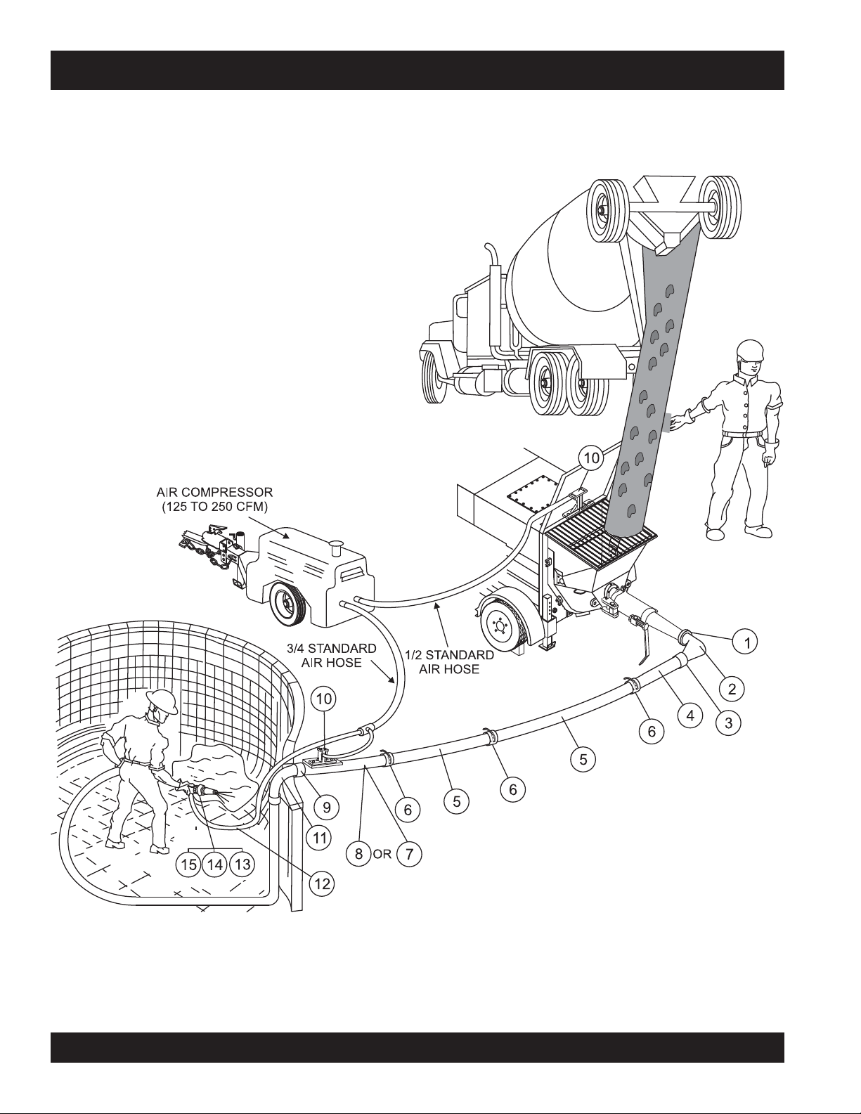
APPENDIX — RECOMMENDED SHOTCRETE SYSTEM
Figure 69. Recommended Shotcrete System
PAGE 80 — MAYCO LS300 CONCRETE PUMP • OPERATION AND PARTS MANUAL — REV. #4 (06/21/10)
Page 81

APPENDIX — RECOMMENDED SHOTCRETE SYSTEM
RECOMMENDED SHOTCRETE SYSTEM
NO. PART NO. PART NAME QTY. REMARKS
1 EM28906 COUPLING, 5” H-D “CF”
2 EM25837 ELBOW, 5"x4”x90°
3 EM28905 COUPLING, 4” H-D w/GASKET & PIN
4 EM402552 REDUCER, 4”x2.5”x53” H-D ENDS
5 EM28061 PIPE, 2.5”x120w x 10’ H-D
6 EM289035 COUPLING, 2.5” H-D w/GASKET & PIN
7 EM28001DD REDUCER, 2.5”x2”x36” H-D
8 EM23815D REDUCER, 2.5”x2” w/AIR VIBRATOR
9 EM28902 COUPLING, 2” H-D w/GASKET & PIN
10 EM23101 AIR VIBRATOR ASSY.
11 EM28131D 2"x2" ELBOW 90
12 EM24841 HOSE, 2”x25’ H-D w/ENDS
13 EM23808D NOZZLE ASSEMBLY, 2” H-D
14 EM23806 NOZZLE TIP, RUBBER 1-3/8”
15 EM23807 NOZZLE TIP, RUBBER 1.25”
GENERAL RECOMMENDATIONS
■
If the site will permit, use steel pipe from the pump to
the pool perimeter. It will reduce line pressures which is
highly recommended.
■
The vibrator on the reducer by the pool improves
pumpability.
■
Turn both air vibrators off whenever the pump is stopped
to prevent separation of mix.
■
The air vibrators are low consumption (4.2 scfm).
■
Leave the air on at the nozzle when the pump is stopped
to prevent clogging of air the hoses in the air insert.
º
■
Use item #11 (steel elbow) at the edge of the pool to
prevent collapse of the rubber hose, which can cause
blockage.
MAYCO LS300 CONCRETE PUMP • OPERATION AND PARTS MANUAL — REV. #4 (06/21/10) — PAGE 81
Page 82

APPENDIX — RECOMMENDED SHOTCRETE ACCESSORIES
RECOMMENDED SHOTCRETE ACCESSORIES
Figure 70. Shotcrete System Accessories
Use a 1-3/8" rubber nozzle tip for a wide spray pattern. Use a 1-1/4" rubber nozzle tip for a narrow spray
pattern. DO NOT INSTALL THE NOZZLE AT THE END OF THE HOSE UNTIL THE FIRST MATERIAL
HAS PASSED THROUGH THE ENTIRE HOSE LENGTH.
Disassemble and clean the nozzle assembly thoroughly after each job. Grease all threads before reassembly.
DO NOT close the air valve when pumping is stopped as a continued air flow keeps the air passages clean.
PAGE 82 — MAYCO LS300 CONCRETE PUMP • OPERATION AND PARTS MANUAL — REV. #4 (06/21/10)
Page 83

APPENDIX — RECOMMENDED SHOTCRETE ACCESSORIES
RECOMMENDED SHOTCRETE ACCESSORIES
NO. PART NO. PART NAME QTY. REMARKS
1 EM26107 HOPPER SCREEN ......................... 1 .......... W/AIR VIBRATOR MOUNTING
2 EM23101 AIR VIBRATOR 1
3 EM132 BOLT, 1/2-13X2 2
4 EM23407 AIR HOSE 1
5 EM23408 BUSHING 1
6 EM23411 VALVE 1
7 EM912073 NIPPLE 2
8 EM23409 COUPLING 1
9 EM923346 WASHER, 1/2 LOCK 2
10 EM406 NUT, HEX 1/2-13 2
11 EM24841 2"X25' HEAVY DUTY HOSE 1
11 EM24844 2"X50' HEAVY DUTY HOSE 1
12
13
14
15
16
17
18
19
20 AIR HOSE ..................................................... NOT SUPPLIED BY MAYCO
21 EM23808 NOZZLE ASSEMBLY ...................... 1 .......... INCLUDES ITEMS W/
EM23802 VIC ADAPTER / EM23802D H.D 1
*
EM23803 GUN BODY 1
*
EM20816 “O” RING 1
*
EM23804 AIR INSERT 1
*
EM23805 NOZZLE CLAMP 1
*
EM23806 NOZZLE TIP, 1-3/8", SHORT 1
*
EM23807 NOZZLE TIP, 1-1/4", LONG 1
*
EM911076 STREET ELBOW 1
*
*
MAYCO LS300 CONCRETE PUMP • OPERATION AND PARTS MANUAL — REV. #4 (06/21/10) — PAGE 83
Page 84

EXPLANATION OF CODE IN REMARKS COLUMN
The following section explains the different symbols and
remarks used in the Parts section of this manual. Use the
help numbers found on the back page of the manual if there
are any questions.
NOTICE
The contents and part numbers listed in the parts
section are subject to change without notice. Multiquip
does not guarantee the availability of the parts listed.
SAMPLE PARTS LIST
NO. PART NO. PART NAME QTY. REMARKS
1 12345 BOLT ......................1 .....INCLUDES ITEMS W/%
2% WASHER, 1/4 IN. ...........NOT SOLD SEPARATELY
2% 12347 WASHER, 3/8 IN. ...1 .....MQ-45T ONLY
3 12348 HOSE ..................A/R ...MAKE LOCALLY
4 12349 BEARING ..............1 .....S/N 2345B AND ABOVE
NO. Column
Unique Symbols — All items with same unique
symbol
QTY. Column
Numbers Used — Item quantity can be indicated by a
number, a blank entry, or A/R.
A/R (As Required) is generally used for hoses or other
parts that are sold in bulk and cut to length.
A blank entry generally indicates that the item is not sold
separately. Other entries will be clarified in the “Remarks”
Column.
REMARKS Column
Some of the most common notes found in the “Remarks”
Column are listed below. Other additional notes needed
to describe the item can also be shown.
Assembly/Kit — All items on the parts list with the
same unique symbol will be included when this item is
purchased.
Indicated by:
“INCLUDES ITEMS W/(unique symbol)”
(@, #, +, %, or >) in the number column belong to the
same assembly or kit, which is indicated by a note in the
“Remarks” column.
Duplicate Item Numbers — Duplicate numbers indicate
multiple part numbers, which are in effect for the same
general item, such as different size saw blade guards in
use or a part that has been updated on newer versions
of the same machine.
NOTICE
When ordering a part that has more than one item
number listed, check the remarks column for help in
determining the proper part to order.
PART NO. Column
Numbers Used — Part numbers can be indicated by a
number, a blank entry, or TBD.
TBD (To Be Determined) is generally used to show a
part that has not been assigned a formal part number
at the time of publication.
A blank entry generally indicates that the item is not sold
separately or is not sold by Multiquip. Other entries will
be clarified in the “Remarks” Column.
Serial Number Break — Used to list an effective serial
number range where a particular part is used.
Indicated by:
“S/N XXXXX AND BELOW”
“S/N XXXX AND ABOVE”
“S/N XXXX TO S/N XXX”
Specific Model Number Use — Indicates that the part
is used only with the specific model number or model
number variant listed. It can also be used to show a
part is NOT used on a specific model or model number
variant.
Indicated by:
“XXXXX ONLY”
“NOT USED ON XXXX”
“Make/Obtain Locally” — Indicates that the part can
be purchased at any hardware shop or made out of
available items. Examples include battery cables, shims,
and certain washers and nuts.
“Not Sold Separately” — Indicates that an item cannot
be purchased as a separate item and is either part of an
assembly/kit that can be purchased, or is not available
for sale through Multiquip.
PAGE 84 — MAYCO LS300 CONCRETE PUMP • OPERATION AND PARTS MANUAL — REV. #4 (06/21/10)
Page 85

SUGGESTED SPARE PARTS
LS300
CONCRETE PUMP
1 Unit
Qty. P/N Description
1 .......... EM16462 .............. FELT HOLDER
4 .......... EM98050 .............. PISTON CUP, ORANGE
4 .......... EM16493 .............. FELT RING
1 .......... EM98033 .............. OIL PLATE
2 .......... EM14408 .............. BRONZE RING
2 .......... EM16145 .............. BUSHING, SWING AXLE (BRONZE )
1 .......... EM98021 .............. WEAR PLATE
2 .......... EM16816-1A ........ ENERGIZER RING
1 .......... EM16816-2 ........... INSERT RING
2 .......... EM98065 .............. SLEEVE SEAL
1 .......... EM98022 .............. WEAR RING
1 .......... EM98065 .............. RUBBER RING
2 .......... EM14407 .............. O-RING
1 .......... 34507 ................... CAP, FUEL
2 .......... EM20763 .............. FILTER, FUEL (IN LINE)
1 .......... P53712 ................. CARTRIDGE, WATER SEPARATOR
3 ......................................... FILTER, OIL (ENGINE)
3 ......................................... FILTER, FUEL (ENGINE)
1 .......... 04115210 ............. ELEMENT, AIR CLEANER
LS300
CONCRETE PUMP
3 Units
Qty. P/N Description
1 .......... EM16459 .............. PIN
2 .......... EM25801 .............. CONCRETE CYLINDER
4 .......... EM16462 .............. FELT HOLDER
6 .......... EM98050 .............. PISTON CUP, ORANGE
8 .......... EM16493 .............. FELT RING
4 .......... EM98033 .............. OIL PLATE
4 .......... EM14408 .............. BRONZE RING
4 .......... EM16145A ............ BUSHING, SWING AXLE (BRONZE )
3 .......... EM98021A ............ WEAR PLATE
4 .......... EM16816-1A ........ ENERGIZER RING
2 .......... EM16816-2 ........... INSERT RING
4 .......... EM98065 .............. SLEEVE SEAL
6 .......... EM98022 .............. WEAR RING
3 .......... EM98065 .............. RUBBER RING
6 .......... EM14407 .............. O-RING
2 .......... EM16174 .............. O-RING
1 .......... EM98138 .............. SWITCH, PROXIMITY
6 .......... 510265 ................. BOLT, HEX HEAD 3/8 NC x 3-1/4 IN. G8
1 .......... 34507 ................... CAP, FUEL
6 .......... EM20763 .............. FILTER, FUEL
3 .......... P53712 ................. CARTRIDGE, WATER SEPARATOR
9 ......................................... FILTER, OIL (ENGINE)
9 ......................................... FILTER, FUEL (ENGINE)
3 .......... 04115210 ............. ELEMENT, AIR CLEANER
Part numbers on this Suggested Spare Parts
List may supersede or replace the P/N shown
in the text pages of this book.
MAYCO LS300 CONCRETE PUMP • OPERATION AND PARTS MANUAL — REV. #4 (06/21/10) — PAGE 85
Page 86
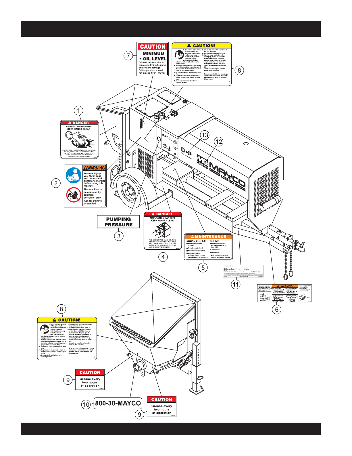
NAMEPLATE AND DECALS
PAGE 86 — MAYCO LS300 CONCRETE PUMP • OPERATION AND PARTS MANUAL — REV. #4 (06/21/10)
Page 87

NAMEPLATE AND DECALS
NO. PART NO. PART NAME QTY. REMARKS
1 DCL301 DECAL, SHUTTLE TUBE DANGER 1
2 35137 DECAL, CAUTION READ MANUAL 1
3 EM97070 DECAL, PUMPING PRESSURE DECAL 1
4 DCL300 DECAL, DANGER LUBRICATION BOX 1
5 EM97084 DECAL, MAINTENANCE 1
6 49002 DECAL, WARNING COUPLER 1
7 EM511091 DECAL, MINIMUM OIL LEVEL 1
8 EM97072 DECAL, CAUTION - OP. INSTRUCTIONS 2
9 EM98000 DECAL, CAUTION - GREASE 2 HOURS 2
10 511709 DECAL, 800-30-MAYCO 1
11 TBD DECAL, VIN IDENTIFICATION 1
12 EM516936 DECAL, LS300 1
13 517907 DIGITAL CONTROL PANEL LOGO 1
MAYCO LS300 CONCRETE PUMP • OPERATION AND PARTS MANUAL — REV. #4 (06/21/10) — PAGE 87
Page 88

NAMEPLATE AND DECALS
PAGE 88 — MAYCO LS300 CONCRETE PUMP • OPERATION AND PARTS MANUAL — REV. #4 (06/21/10)
Page 89

NAMEPLATE AND DECALS
NO. PART NO. PART NAME QTY. REMARKS
1 DCL301 DECAL, SHUTTLE TUBE DANGER 1
2 EM995 DECAL, CAUTION DIESEL FUEL 1
3 DCL304 DECAL, DANGER IMPROPER CHARGING 1
4 EM955 DECAL, DANGER CHARGING ACCUM. 1
5 DCL302 DECAL, WARNING BURN HAZARD 1
6 EM696 DECAL, CAUTION - TOWING DECAL 1
7 SERIAL PLATE ...................................................... 1 .......... CONTACT MQ PARTS DEPT.
8 EM985 DECAL, HYDRAULIC OIL ONLY 1
9 EM516937 DECAL, LS300 1
MAYCO LS300 CONCRETE PUMP • OPERATION AND PARTS MANUAL — REV. #4 (06/21/10) — PAGE 89
Page 90

FRAME ASSY.
PAGE 90 — MAYCO LS300 CONCRETE PUMP • OPERATION AND PARTS MANUAL — REV. #4 (06/21/10)
Page 91

NO. PART NO. PART NAME QTY. REMARKS
1 516758 FRAME, MAIN 1
2 516581 CHAIN, TRAILER HITCH 2
3 EM25610 JACK STAND, FRONT 1
4 EM744 CLEVIS PIN 2
5 EM491686 PIN 2
6 EM963055 HHB 3/8 NC X 3/4 G5 5
7 0166 A WASHER, LOCK 3/8" MED 5
10 518025 FENDER, BOLT ON, RIGHT 1
11 518026 FENDER, BOLT ON, LEFT 1
12 504456 BOLT 1/2"NC X 3/4" G5 10
13 6109180 WASHER, LOCK 1/2" 10
14 EM70186 STABILIZER STAND 2
15 EM491744 RIVET, POP AM-44 2
FRAME ASSY.
MAYCO LS300 CONCRETE PUMP • OPERATION AND PARTS MANUAL — REV. #4 (06/21/10) — PAGE 91
Page 92

AXLE ASSY.
PAGE 92 — MAYCO LS300 CONCRETE PUMP • OPERATION AND PARTS MANUAL — REV. #4 (06/21/10)
Page 93

AXLE ASSY.
AXLE ASSY. (RIGHT/LEFT)
NO. PART NO. PART NAME QTY. REMARKS
1 516931 AXLE, TORSION BAR ASSY. 1
2 EM092305 BRAKE ASSY COMPLETE, RIGHT ................ 1 .............. INCLUDES ITEMS W/#
2 EM092306 BRAKE ASSY COMPLETE, LEFT .................. 1 .............. INCLUDES ITEMS W/%
.......................................................................................... SEE NOTE BELOW
3 363198 OIL SEAL 1
4 363196 INNER BEARING CONE 2 IN. 1
5 383911 INNER BEARING CUP 2 IN. 1
6#% 363909 WHEEL STUD 1/2 IN. - 20 UNF PRESS IN 8
7 363239 HUB AND DRUM ASSY. 2
8 363916 OUTER BEARING CONE 1
9 363420 OUTER BEARING CUP 1
10 568326 LOAD WASHER 1 IN. T5 HP 1
11 363257 SLOTTED NUT, 1 IN. UNF 2
12 363258 COTTER PIN 3/16 IN. X 1-1/2 2
13 EM515479 RIM AND TIRE 2
14 26519 WHEEL LUG NUTS 1/2 UNF 60 CON 8
15 516482 GREASE CAP 2
16 EM963692 CAPSCREW, 1/2-13X1-1/2 HHCS 4
17 EM621 WASHER, 1/2" 8
18 EM092305 NUT, LOCK 1/2" 4
RIGHT AND LEFT SIDE AXLE
ASSEMBLIES ARE IDENTICAL WITH
THE EXCEPTION OF THE BRAKE
ASSEMBLY.
MAYCO LS300 CONCRETE PUMP • OPERATION AND PARTS MANUAL — REV. #4 (06/21/10) — PAGE 93
Page 94

BRAKE LINE ASSY.
PAGE 94 — MAYCO LS300 CONCRETE PUMP • OPERATION AND PARTS MANUAL — REV. #4 (06/21/10)
Page 95

BRAKE LINE ASSY.
NO. PART NO. PART NAME QTY. REMARKS
1 34566 KIT, MAIN BRAKE LINE 1
2 EM512877 ADAPTOR, STRAIGHT 2
3 EM512876 ADAPTOR, ELBOW 2
4 34565 KIT, WHEEL BRAKE LINE 1
MAYCO LS300 CONCRETE PUMP • OPERATION AND PARTS MANUAL — REV. #4 (06/21/10) — PAGE 95
Page 96

BRAKE LIGHT ASSY.
PAGE 96 — MAYCO LS300 CONCRETE PUMP • OPERATION AND PARTS MANUAL — REV. #4 (06/21/10)
Page 97

BRAKE LIGHT ASSY.
NO. PART NO. PART NAME QTY. REMARKS
1 26536 BRAKE LIGHT ASSY. 2
2 515419 HARNESS ASSY. W/RECEPTACLES 1
MAYCO LS300 CONCRETE PUMP • OPERATION AND PARTS MANUAL — REV. #4 (06/21/10) — PAGE 97
Page 98
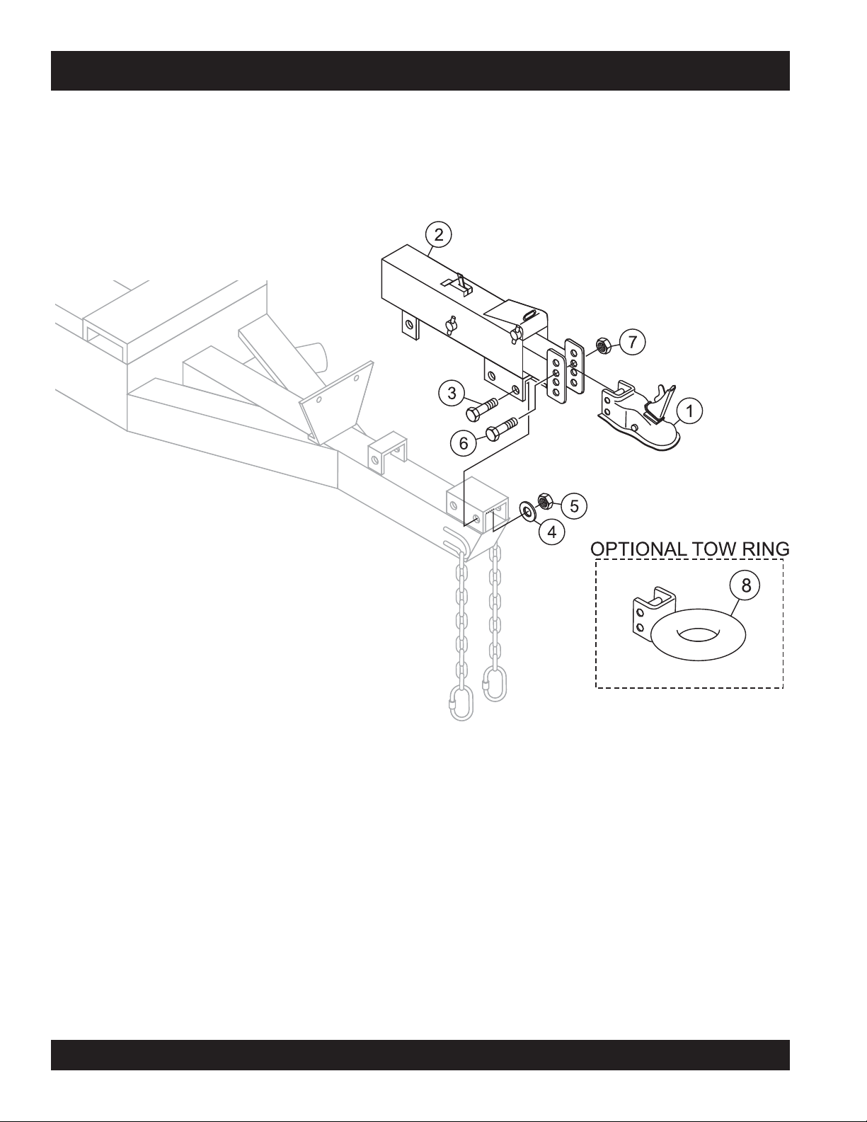
TRAILER HITCH ASSY.
PAGE 98 — MAYCO LS300 CONCRETE PUMP • OPERATION AND PARTS MANUAL — REV. #4 (06/21/10)
Page 99

TRAILER HITCH ASSY.
NO. PART NO. PART NAME QTY. REMARKS
1 EM29228 COUPLING, TRAILER 2 IN.BALL, 6000 LBS 1
2 EM19067 ACTUATOR, BRAKE 1
3 EM503111 BOLT, HEX HEAD 1/2 NC X 4-1/2 IN. 3
4 EM492600 WASHER, FLAT 1/2 IN. 3
5 EM492584 NUT, LOCK 1/2
6 EM507658 BOLT, HEX HEAD 5/8 NC X 4-1/2
7 EM492586 NUT, LOCK 5/8 IN. 2
8 16137 TOW RING, 3 IN. LUNETTE EYE
IN. 3
IN. G5 2
1
MAYCO LS300 CONCRETE PUMP • OPERATION AND PARTS MANUAL — REV. #4 (06/21/10) — PAGE 99
Page 100
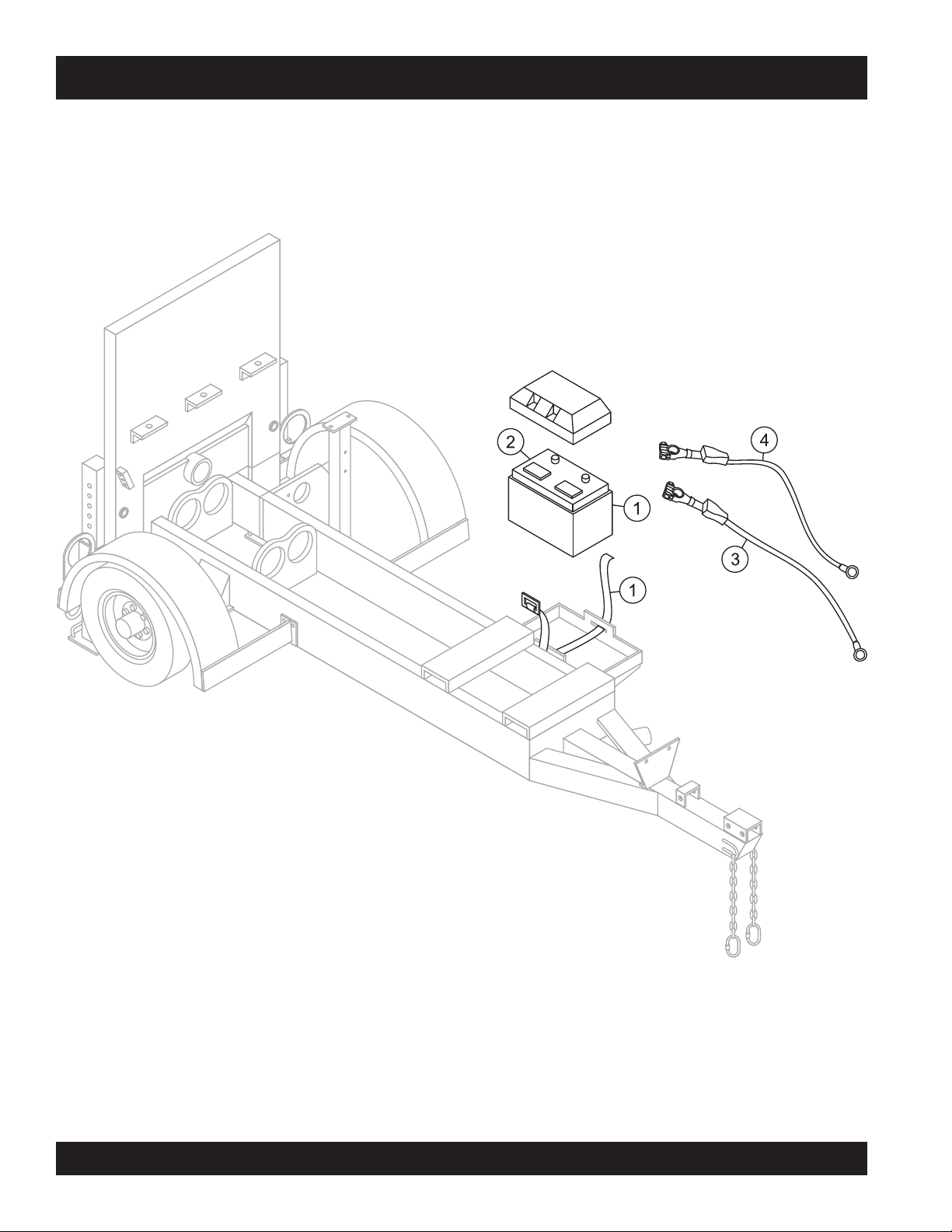
BATTERY ASSY.
PAGE 100 — MAYCO LS300 CONCRETE PUMP • OPERATION AND PARTS MANUAL — REV. #4 (06/21/10)
 Loading...