

Page 1

OPERATION AND PARTS MANUAL
JWN-SERIES
RIDE-ON POWER TROWEL
HONDA GX670TAF 24 HP ENGINE
Revision #8 (12/18/07)
To find the latest revision of this
publication, visit our website at:
www.multiquip.com
THIS MANUAL MUST ACCOMPANY THE EQUIPMENT AT ALL TIMES.
P/N 20214
Page 2

JWN-SERIES — PROPOSITION 65 WARNING
Engine exhaust and some of
its constituents, and some dust created
by power sanding, sawing, grinding,
drillingandotherconstructionactivities
contains chemicals known to the State
of California to cause cancer, birth
defects and other reproductive harm.
Some examples of these chemicals are:
Leadfromlead-basedpaints.
Crystallinesilicafrombricks.
Cementandothermasonryproducts.
Arsenicandchromiumfrom chemically
treatedlumber.
Your risk from these exposures varies,
dependingonhowoftenyoudothistype
of work. To reduce your exposure to
these chemicals: work in aALWAYS
well ventilated area, and work with
approved safety equipment, such as
dust masks that are specially designed
to filter out microscopic particles.
Page 3
JWN-SERIES — SILICOSIS/RESPIRATORY WARNINGS
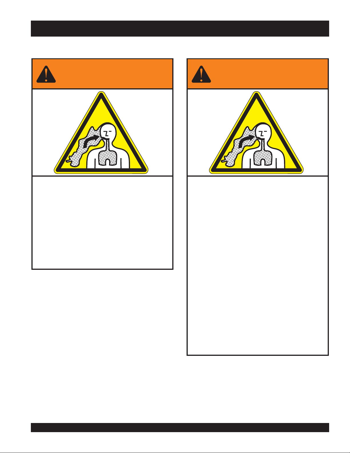
WARNING
SILICOSIS WARNING RESPIRATORY HAZARDS
Grinding/cutting/drilling of masonry, concrete, metal and
other materials with silica in their composition may give
off dust or mists containing crystalline silica. Silica is a
basic component of sand, quartz, brick clay, granite and
numerous other minerals and rocks. Repeated and/or
substantial inhalation of airborne crystalline silica can
cause serious or fatal respiratory diseases, including
silicosis. In addition, California and some other
authorities have listed respirable crystalline silica as a
substance known to cause cancer. When cutting such
materials, always follow the respiratory precautions
mentioned above.
WARNING
Grinding/cutting/drilling of masonry, concrete, metal and
other materials can generate dust, mists and fumes
containing chemicals known to cause serious or fatal
injury or illness, such as respiratory disease, cancer,
birth defects or other reproductive harm. If you are
unfamiliar with the risks associated with the particular
process and/or material being cut or the composition of
the tool being used, review the material safety data
sheet and/or consult your employer, the material
manufacturer/supplier, governmental agencies such as
OSHA and NIOSH and other sources on hazardous
materials. California and some other authorities, for
instance, have published lists of substances known to
cause cancer, reproductive toxicity, or other harmful
effects.
Control dust, mist and fumes at the source where
possible. In this regard use good work practices and
follow the recommendations of the manufacturers or
suppliers, OSHA/NIOSH, and occupational and trade
associations. Water should be used for dust
suppression when wet cutting is feasible. When the
hazards from inhalation of dust, mists and fumes cannot
be eliminated, the operator and any bystanders should
always wear a respirator approved by NIOSH/MSHA for
the materials being used.
JWN- SERIES • RIDE-ON POWER TROWEL — PARTS AND OPERATION MANUAL — REV. #8 (12/18/07) — PAGE 3
Page 4

JWN-SERIES — TABLE OF CONTENTS
MQ WHITEMAN — JWN-SERIES
RIDE-ON POWER TROWEL
Proposition 65 Warning ............................................. 2
Silicosis/Respiratory Warnings .................................. 3
Table of Contents ...................................................... 4
Parts Ordering Procedures ....................................... 5
Training Checklist ...................................................... 6
Daily Pre-Operation Checklist ................................... 7
Safety Message Alert Symbols .............................. 8-9
Rules For Safe Operation .................................. 10-13
Specifications (Trowel) ............................................ 14
Specifications (Engine) ........................................... 15
General Information ................................................ 16
Controls and Indicators ...................................... 17-18
Basic Engine ........................................................... 19
New Machine Setup Instructions ............................ 20
Initial Start-Up ....................................................21-23
Maintenance ...................................................... 24-35
Troubleshooting (Engine) ................................... 36-37
Troubleshooting (Trowel) ................................... 38-39
Explanation of Codes In Remarks Column ............. 40
Suggested Spare Parts & Service Items................. 41
Nameplate and Decals....................................... 42-43
Pivot Assembly (Left/Right) ................................ 44-45
Steering Handles Assembly (Left/Right) ............ 46-47
Steering Control Assembly (Left/Right) ............. 48-49
Gearbox Assembly (Right) ................................. 50-51
Gearbox Assembly (Left) ................................... 52-53
Twin Pitch Handle Assembly (Left/Right) ........... 54-55
Twin Pitch Tower Assembly (Left/Right) .............56-57
Twin Pitch Miter Box Assembly (Left/Right) ....... 58-59
Drive Assembly .................................................. 60-61
Muffler/Belt Assembly ........................................ 62-63
Beltguard Assembly ........................................... 64-65
Spider Assembly (Right) .................................... 66-67
Spider Assembly (Left)....................................... 68-69
Yoke Assembly ...................................................70-71
Foot Pedals/Throttle Assembly .......................... 72-73
Control Panel Assembly ..................................... 74-75
Frame/Fuel Assembly ........................................76-77
Battery Assembly ............................................... 78-79
Spray Assembly ................................................. 80-81
Light Assembly ................................................... 82-83
Seat Frame Assembly ........................................ 84-85
EZ-Mover Assembly ........................................... 86-87
HONDA GX-670-TAF ENGINE
Air Cleaner Assembly......................................... 88-89
Camshaft Assembly ........................................... 90-91
Carburetor Assembly ......................................... 92-93
Control Assembly ............................................... 94-95
Control Box Assembly ........................................ 96-97
Crankcase Cover Assembly ...............................98-99
Crankshaft Assembly .....................................100-101
Cylinder Barrel Assembly ............................... 102-103
Cylinder Head Assembly ................................ 104-105
Fan Cover Assembly ...................................... 106-107
Flywheel Assembly ........................................ 108-109
Fuel Pump Assembly .....................................110-111
Ignition Coil Assembly .................................... 112-113
Labels Assembly ............................................114-115
Oil Cooler Assembly ....................................... 116-117
Piston & Connecting Rod Assembly .............. 118-119
Starter Motor Assembly ................................. 120-121
Terms And Conditions Of Sale .............................. 122
PAGE 4 — HTN 31V
JWN-SERIES • RIDE-ON POWER TROWEL — PARTS AND OPERATION MANUAL — REV. #8 (12/18/07) — PAGE 4
Page 5
PARTS ORDERING PROCEDURES
Ordering parts has never been easier!
Choose from three easy options:
Effective:
January 1
st
, 2006
Best Deal!
Order via Internet (Dealers Only):
Order parts on-line using Multiquip’s SmartEquip website!
■
View Parts Diagrams
■
Order Parts
■
Print Specification Information
Goto www.multiquip.com and click on
Order Parts
to log in and save!
Order via Fax (Dealers Only):
All customers are welcome to order parts via Fax.
Domestic (US) Customers dial:
1-800-6-PARTS-7 (800-672-7877)
Non-Dealer Customers:
Contact your local Multiquip Dealer for
parts or call 800-427-1244 for help in
locating a dealer near you.
Order via Phone:
If you have an MQ Account, to obtain a
Username and Password, E-mail us at:
parts@multiquip.com.
To obtain an MQ Account, contact your
District Sales Manager for more information.
internet
Use the
on
Standard orders
and qualify for a 5% Discount
for all orders which include
complete part numbers.*
Fax
your order in and qualify for a 2% Discount
on
Standard orders
for all orders which include
complete part numbers.*
Domestic (US) Dealers Call:
1-800-427-1244
International Customers
their local Multiquip Representatives for
Parts Ordering information.
Note: Discounts Are Subject To Change
Note: Discounts Are Subject To Change
should contact
When ordering parts, please supply:
❒❒
❒
❒❒
❒
Dealer Account Number
❒❒
❒❒
❒
Dealer Name and Address
❒❒
❒❒
❒
Shipping Address (if different than billing address)
❒❒
❒❒
❒
Return Fax Number
❒❒
❒❒
❒
Applicable Model Number
❒❒
❒❒
❒
Quantity, Part Number and Description of Each Part
❒❒
All orders are treated as
Standard Orders
and will ship the same day if received prior
to 3PM PST.
www.multiquip.com
WE ACCEPT ALL MAJOR CREDIT CARDS!
JWN- SERIES • RIDE-ON POWER TROWEL — PARTS AND OPERATION MANUAL — REV. #8 (12/18/07) — PAGE 5
Specify Preferred Method of Shipment:
❒❒
✓
UPS/Fed Ex
■
Priority One
■
Ground
■ Next Day
■
Second/Third Day
✓ DHL
✓
Tr u c k
Page 6

JWN-SERIES — TRAINING CHECKLIST
TRAINING CHECKLIST
This checklist will lists some of the minimum requirements for machine maintenance and operation. Please feel free to detach it and
make copies. Use this checklist whenever a new operator is to be trained or it can be used as a review for more experienced
operators.
TSILKCEHCGNINIART
.ON NOITPIRCSED ?KO ETAD
1 .yletelpmoclaunaMs’rotarepOdaeR
2
3 .erudecorpgnileufer,metsysleuF
4 .)deppiuqefi(sthgildnayarpsfonoitarepO
5 .)gninnurtonenihcam(slortnocfonoitarepO
6 .noitarepo"hctiwsllik"taes,slortnocytefaS
7 .serudecorppotsycnegremE
8 .enihcamfoputratS
9 .revohagniniatniaM
01 .gnirevuenaM
11 .gnihctiP
21
dnaenignefognikcehc,stnenopmocfonoitacol,tuoyalenihcaM
.slevelliociluardyh
ehtgnigagnesid,™hctiPniwTsrewotneewtebhctipedalbgnihctaM
.egaknil
31 .seuqinhcetgnihsinifetercnoC
41 .enihcamfonwodtuhS
51 .)spooltfil(enihcamfognitfiL
61 .egarotsdnatropsnartenihcaM
Operator _________________________________________ Trainee __________________________________________
COMMENTS:
PAGE 6 — HTN 31V
JWN-SERIES • RIDE-ON POWER TROWEL — PARTS AND OPERATION MANUAL — REV. #8 (12/18/07) — PAGE 6
Page 7

JWN-SERIES — DAILY PRE-OPERATION CHECKLIST
DAILY PRE-OPERATION CHECKLIST
TSILKCEHCNOITAREPO-ERPYLIAD
1
2
3 .leveLtnalooCrotaidaR
4 sedalBfonoitidnoC
5 .noitarepOhctiPedalB
6 .noitarepOhctiwSpotS-ytefaS
7 .noitarepOlortnoCgnireetS
8 .stleBfonoitidnoC
COMMENTS:
diulFxobraeGleveL
.leveLliOenignE
.
.
JWN- SERIES • RIDE-ON POWER TROWEL — PARTS AND OPERATION MANUAL — REV. #8 (12/18/07) — PAGE 7
Page 8
JWN-SERIES — SAFETY MESSAGE ALERT SYMBOLS
FOR YOUR SAFETY AND THE SAFETY OF OTHERS!
Safety precautions should be followed at all times when
operating this equipment. Failure to read, understand and
comply with the Safety Messages and Operating Instructions
could result in injury to yourself and others.
This Operation Manual has been
developed to provide instructions for the
safe and efficient operation of the JWN Series Ride-On Trowel. For engine
maintenance information, please refer to the
engine manufacturer's instructions for data
relative to its safe operation.
Before using this Ride-On Trowel, ensure that the operating
individual has read, understands, and complies with all
instructions in this manual.
SAFETY MESSAGE ALERT SYMBOLS
The three (3) Safety Messages shown below will inform you
about potential hazards that could injure you or others. The
Safety Messages specifically address the level of exposure to
the operator, and are preceded by one of three words: DANGER,
WARNING, or CAUTION.
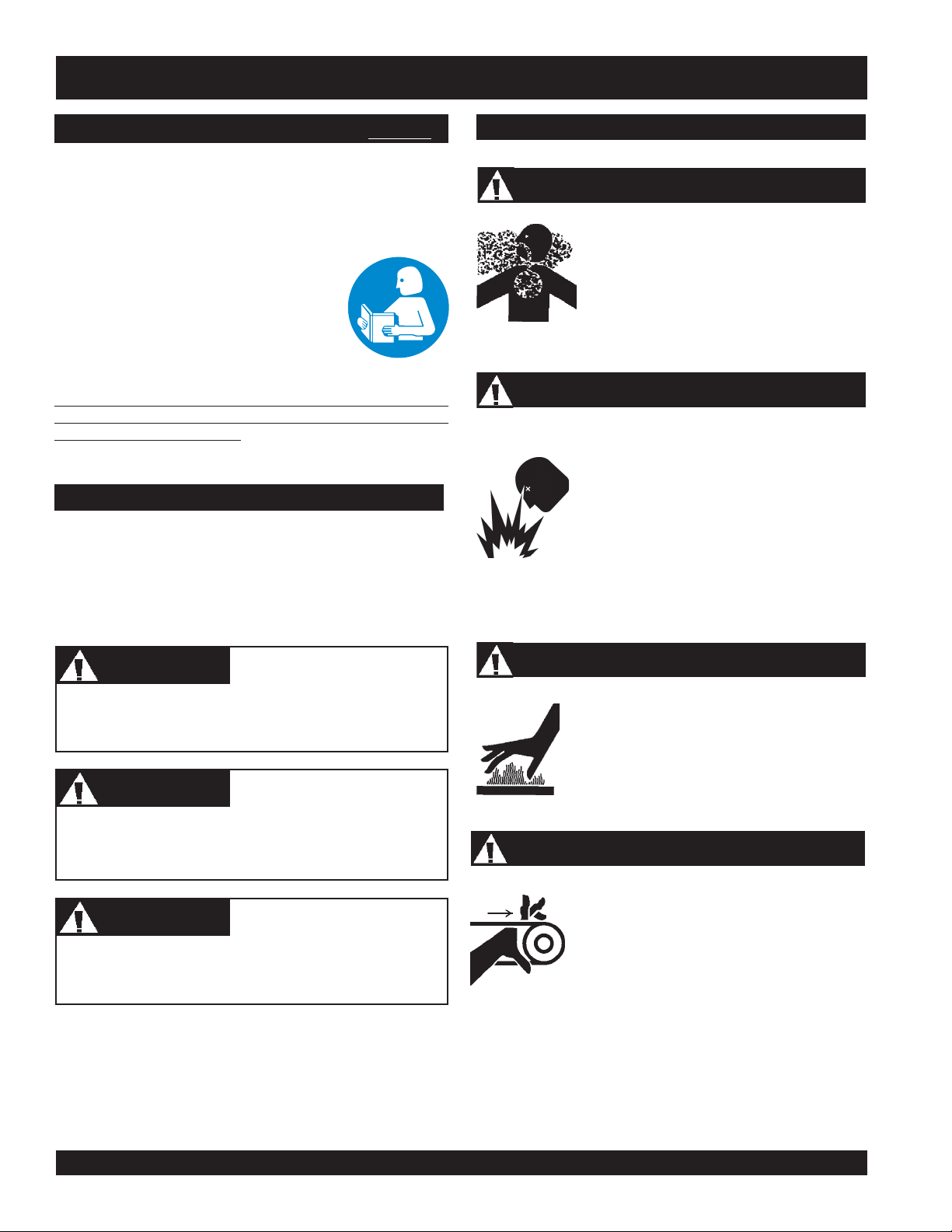
HAZARD SYMBOLS
Lethal Exhaust Gases
Engine exhaust gases contain poisonous
carbon monoxide. This gas is colorless and
odorless, and can cause death if inhaled.
NEVER operate this equipment in a confined
area or enclosed structure that does not
provide ample free flow air.
Explosive Fuel
Gasoline is extremely flammable, and its
vapors can cause an explosion if ignited. DO
NOT start the engine near spilled fuel or
combustible fluids. DO NOT fill the fuel tank
while the engine is running or hot. DO NOT
overfill tank, since spilled fuel could ignite if it
comes into contact with hot engine parts or
sparks from the ignition system. Store fuel in
approved containers, in well-ventilated areas
and away from sparks and flames. NEVER
use fuel as a cleaning agent.
DANGERDANGER
DANGER
DANGERDANGER
You WILL be
if you DO NOT follow these directions.
WARNINGWARNING
WARNING
WARNINGWARNING
You CAN be KILLED or
you DO NOT follow these directions.
CAUTICAUTI
CAUTION
CAUTICAUTI
You CAN be
these directions.
Potential hazards associated with trowel operation will be
referenced with Hazard Symbols which appear throughout this
manual, and will be referenced in conjunction with Safety
Message Alert Symbols.
KILLED
INJURED
or
SERIOUSLY INJURED
SERIOUSLY INJURED
if you DO NOT follow
if
Burn Hazards
Engine components can generate extreme heat.
To prevent burns, DO NOT touch these areas
while the engine is running or immediately after
operations. NEVER operate the engine with
heat shields or heat guards removed.
Rotating Parts
NEVER operate equipment with covers, or
guards removed. Keep
and
clothing
prevent injury.
away from all moving parts to
fingers, hands, hair
PAGE 8 — HTN 31V
JWN-SERIES • RIDE-ON POWER TROWEL — PARTS AND OPERATION MANUAL — REV. #8 (12/18/07) — PAGE 8
Page 9
JWN-SERIES — SAFETY MESSAGE ALERT SYMBOLS
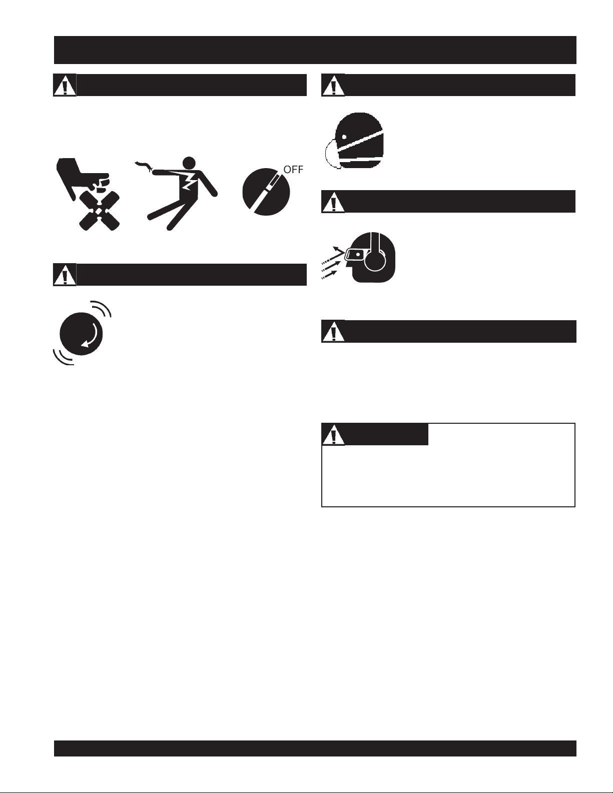
Accidental Starting Respiratory Hazard
Accidental starts can cause severe injury or death. ALWAYS
place the ON/OFF switch in the OFF position. Disconnect and
ground spark plug lead and disconnect negative battery cable
from battery before servicing.
Over Speed Conditions
NEVER tamper with the factory settings of the
engine governor or settings. Personal injury
and damage to the engine or equipment can
result if operating in speed ranges above
maximum allowable.
Other important messages are provided throughout this manual
to help prevent damage to your trowel, other property, or the
surrounding environment.
ALWAYS wear approved respiratory
protection.
Sight and Hearing hazard
ALWAYS wear approved eye and hearing
protection.
Equipment Damage Messages
CAUTIONCAUTION
CAUTION
CAUTIONCAUTION
This
Ride-On trowel
surrounding environment could be damaged if you do
not follow instructions.
, other property, or the
JWN- SERIES • RIDE-ON POWER TROWEL — PARTS AND OPERATION MANUAL — REV. #8 (12/18/07) — PAGE 9
Page 10
JWN-SERIES — RULES FOR SAFE OPERATION
■
RULES FOR SAFE OPERATION
WARNINGWARNING
WARNING
WARNINGWARNING
Failure to follow instructions in this manual may lead to serious
injury or even death! This equipment is to be operated by
trained and qualified personnel only! This equipment is for
industrial use only.
The following safety guidelines should always be used when
operating the JWN-SERIES Ride-On Trowel.
SAFETY
■
DO NOT operate or service this equipment
before you read, understand, and comply
with all safety messages in this manual.
The manual must be kept available and
accessible to the operator.
■
This equipment should not be operated by persons under the
minimum statutory age limit.
■
NEVER use this machine for any purpose other than those
described in this manual.
■
NEVER operate the trowel without proper protective clothing,
shatterproof glasses, steel-toed boots and other protective
devices required for the job.
NEVER operate this equipment when not feeling well due to
fatigue, illness or taking medicine.
■
NEVER operate the trowel under the influence of drugs or
alcohol.
■
Replace nameplate, operation and safety decals when they
become difficult to read.
■
ALWAYS check the trowel for loosened hardware such as
nuts and bolts before starting.
■
NEVER touch the hot exhaust manifold, muffler
or cylinder. Allow these parts to cool before
servicing the trowel. Contact with
components can cause serious burns.
■
The engine of this trowel requires an adequate free flow of
cooling air. NEVER operate the trowel in any enclosed or
■
ALWAYS refuel in a well-ventilated area, away from sparks
and open flames.
hot!
narrow area where free flow of
the air is restricted. If the air flow
is restricted it will cause serious
damage to the engine and may
cause injury to people.
Remember the engine gives off
DEADLY
gas.
carbon monoxide
■
Topping-off to filler port is dangerous, as it tends to spill fuel.
■
NEVER use fuel as a cleaning agent.
■
ALWAYS use extreme caution when working with flammable
liquids. When refueling, STOP the engine. Allow the engine
to cool before adding fuel or performing service and
maintenance functions.
■
NEVER operate the trowel in an
■
NEVER use accessories or attachments which are not
recommended by the manufacturer for this equipment.
Damage to the equipment and/or injury to user may result.
■
Manufacturer does not assume responsibility for any accident
due to equipment modifications. Unauthorized equipment
modification will void all warranties. Any modification which
could lead to a change in the original characteristics of the
machine should be made only by the manufacturer who shall
confirm that the machine is in conformity with appropriate
safety regulations.
PAGE 10 — HTN 31V
JWN-SERIES • RIDE-ON POWER TROWEL — PARTS AND OPERATION MANUAL — REV. #8 (12/18/07) — PAGE 10
explosive atmosphere where fumes
are present, or near combustible
materials. An explosion or fire could
result in severe
death.
■
NEVER
Fire or explosion could result from
vapors
smoke
, or if fuel is spilled on a
bodily harm or even
around or near the machine.
fuel
hot!
engine.
Page 11

JWN-SERIES — RULES FOR SAFE OPERATION
■
NEVER run engine without air filter. Severe engine damage
may occur. Service air filter frequently to prevent carburetor
malfunction.
■
NEVER place your
while starting or operating this equipment.
■
AVOID wearing jewelry or loose fitting clothing that may snag
on the controls or moving parts as this can cause a serious
injury.
■
ALWAYS keep clear of
operating the trowel.
■
Moving Parts – Shut down the engine before performing
service or maintenance functions. Contact with moving parts
can cause serious injury.
■
ALWAYS check to make sure that the operating area is clear
before starting the engine.
■
NEVER leave the machine
■
ALWAYS be sure the operator is familiar with proper safety
precautions and operations techniques before using trowel.
feet
or
rotating
hands
inside the guard rings
or
moving parts
unattended
while running.
while
Lifting the Ride-On Trowel
DANGERDANGER
DANGER
DANGERDANGER
Pay close attention to ventilation when
operating the trowel in confined spaces
such as tunnels, buildings or similar areas.
The engine exhaust contains harmful
elements. Ensure proper air flow to move
engine exhaust away from the operator.
CAUTIONCAUTION
CAUTION
CAUTIONCAUTION
heavy
This ride-on trowel is very
around. Use proper heavy lifting procedures and DO NOT
attempt to lift the ride-on trowel by the guard rings.
and awkward to move
■
ALWAYS keep the work area well organized.
■
ALWAYS clear the work area of any debris, tools, etc. that
would constitute a hazard while the trowel is in operation.
WARNINGWARNING
WARNING
WARNINGWARNING
ALWAYS check to make sure that the operating area is
clear before starting the engine.
■
No one other than the operator is to be in the working area
when the trowel is in operation.
■
NEVER allow passengers or riders on the trowel during
operation.
■
Always observe all applicable compulsory regulations
relevant to environmental protection, especially, fuel storage,
the handling of hazardous substances, and the wearing of
protective clothing and equipment. Instruct the user as
necessary, or, as the user, request this information and
training.
■
ALWAYS store equipment properly when it is not being used.
Equipment should be stored in a clean, dry location out of
the reach of children.
The JWN-SERIES Ride-On Power Trowel is designed to be
moved and handled several ways.
The easiest way to lift the trowel is to utilize the lift loops that are
welded to the frame. These lift loops are located to the left and
right sides of the operator’s seat.
A strap or chain can be attached to these lift loops, allowing a
forklift or crane to lift the trowel up onto and off of a slab of concrete.
The strap or chain should have a minimum 2,000 pounds (1000kg) lifting capacity and the lifting gear must be capable of lifting
at least this amount.
DANGERDANGER
DANGER
DANGERDANGER
NEVER stand under or allow anyone
else to stand under the trowel while it
is being lifted.
JWN- SERIES • RIDE-ON POWER TROWEL — PARTS AND OPERATION MANUAL — REV. #8 (12/18/07) — PAGE 11
Page 12
JWN-SERIES — RULES FOR SAFE OPERATION
Transporting
■
ALWAYS shutdown engine before transporting.
■
Tighten fuel tank cap securely and close fuel petcock to
prevent fuel from spilling.
■
Drain fuel when transporting trowel for long distances or over
bad roads.
■
When placing the trowel on a truck-bed for transport,
tie-down the trowel.
■
If the trowel is being transported via a trailer, make sure the
trailer complies with all local and state safety transportation
laws. Refer to the following "
for basic towing techniques.
Towing Safety Precautions"
always
■
■
■
■
■
■
■
Use chock-blocks at each wheel when parked to prevent
trailer from rolling.
Use the trailer's swivel jack to adjust the trailer height to a
level position while parked.
Avoid sudden stops and starts. This can cause the trailer to
skid or jack-knife. Smooth, gradual starts and stops will
improve towing.
Avoid sharp turns.
Trailer should be adjusted to a level position at all times
when towing.
Raise and lock trailer wheel stand in the "UP" position when
transporting.
DOT requirements include the following:
Towing Safety Precautions
CAUTIONCAUTION
CAUTION
CAUTIONCAUTION
Conform to
Towing Regulations
roads.
To reduce the possibility of an accident while transporting the
trowel on public roads, always make sure the trailer that supports
the trowel and the towing vehicle are in good operating condition
and both units are mechanically sound.
The following list of suggestions should be used when towing
your trowel:
■
Make sure the hitch and coupling of the towing vehicle are
rated equal to, or greater than the trailer "gross vehicle weight
rating" (GVWR) of 6,000 lbs.
■
ALWAYS inspect the hitch and coupling for wear. NEVER
tow a trailer with defective hitches, couplings, chains, etc.
■
Check the tire air pressure on both towing vehicle and trailer.
Trailer tires should be inflated to 50 psi cold
the tire tread wear on both vehicles.
■
ALWAYS make sure the trailer is equipped with "Safety
Chains ".
■
ALWAYS attach trailer's safety chains to towing vehicle
properly.
■
ALWAYS make sure the vehicle and trailer directional,
backup, brake, and trailer lights are connected and working
■
DO NOT exceed the recommended highway speed when
towing. Unless posted otherwise, do not exceed 45 MPH
highway, and 10 MPH off-road.
JWN-SERIES • RIDE-ON POWER TROWEL — PARTS AND OPERATION MANUAL — REV. #8 (12/18/07) — PAGE 12
Department of Transportation (DOT) Safety
before transporting trowel on public
. Also check
PAGE 12 — HTN 31V
Connect and test electric brake operation.
Secure portable power cables in cable tray with tie wraps.
Battery
The battery contains acids that can cause injury to the eyes and
skin. To avoid eye irritation,
shielding. Use well insulated gloves when picking the battery
up. Use the following guidelines when handling the battery.
■
DO NOT drop the battery. Any impact to
the battery may cause it to explode.
■
DO NOT expose the battery to open flames,
sparks, lit cigarettes etc. The battery
contains combustible gases and liquids. If
these gases and liquids come in contact
with a flame or spark an explosion can occur.
■
ALWAYS keep the battery charged. If the
battery is not charged a buildup of combustible gas will occur.
■
ALWAYS keep battery cables in good working condition.
Repair or replace all worn cables.
■
ALWAYS disconnect the
performing service on the trowel.
■
ALWAYS recharge the battery in a vented air environment
to avoid risk of a dangerous concentration of combustible
gases.
■
In case the battery liquid, (dilute sulfuric acid), comes in contact
clothing or skin
with
with plenty of water.
■
In case the battery liquid, (dilute sulfuric acid), comes in contact
eyes
with your
then contact the nearest doctor or hospital and seek medical
attention.
, rinse eyes immediately with plenty of water,
always
, rinse skin or clothing immediately
wear safety glasses or face
negative battery terminal
before
Page 13
JWN-SERIES — RULES FOR SAFE OPERATION
Maintenance Safety
■
ALWAYS shut down the engine and disconnect battery before
performing service or maintenance functions. Contact with
moving parts can cause serious injury.
■
Securely support any trowel components that must be raised.
■
NEVER lubricate components or attempt service on a running
trowel.
■
ALWAYS allow the trowel a proper amount of time to cool
before servicing.
■
Keep the trowel in proper running condition.
■
Make sure that there is no buildup of concrete, grease, oil or
debris on the machine.
■
Repair damage to the trowel immediately and always replace
broken parts.
■
Dispose of hazardous waste properly. Examples of potentially
hazardous waste are used motor oil, fuel and fuel filters.
■
DO NOT use plastic food containers to dispose of hazardous
waste.
■
DO NOT pour waste oil or fuel directly onto the ground, down
a drain or into any water source.
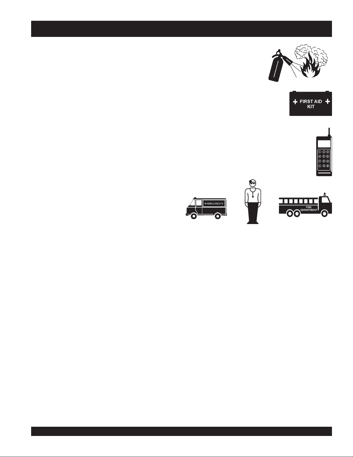
Emergencies
■
■
■
ALWAYS know the location of
the nearest
ALWAYS know the location of the
nearest
Know the phone numbers of the nearest
ambulance, doctor
that a phone or radio is readily available at the
jobsite. If this is not possible, know the location of
the nearest phone. This information will be
invaluable in the event of an emergency.
fire extinguisher
first aid kit
.
and
.
fire department
. Ensure
■
NEVER store trowel with fuel in the tank for any extended
period of time. Always clean up spilled fuel immediately.
JWN- SERIES • RIDE-ON POWER TROWEL — PARTS AND OPERATION MANUAL — REV. #8 (12/18/07) — PAGE 13
Page 14
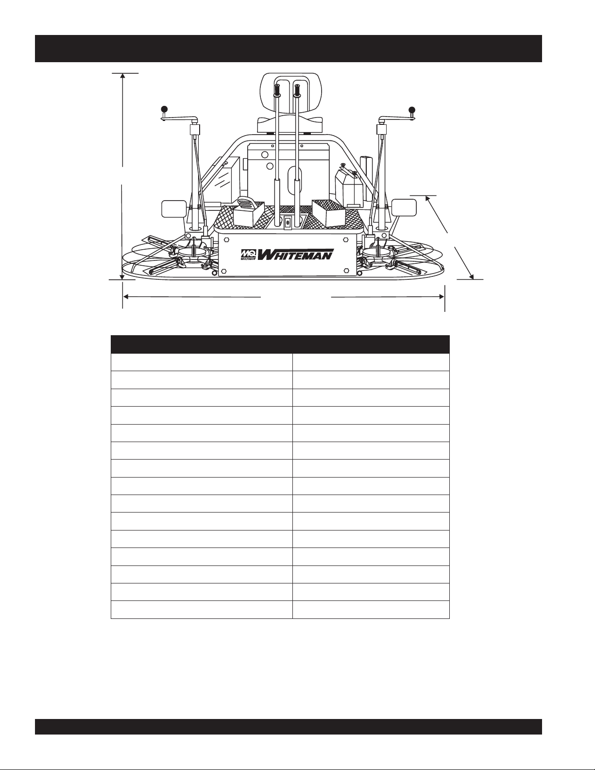
C = 46.75 inches
Figure 1. JWN-Series Dimensions Specifications
JWN-SERIES— SPECIFICATIONS (TROWEL)
B =39 inches
A = 77 inches
snoitacificepSseireSNWJ.2elbaT
)mc(.ni–htgneL–A )6.591(0.77
)mc(.ni–htdiW–B )99(93
1
)mc(.ni–thgieH–C
)7.811(57.64
gnitarepO).sgk(.sbl–thgieW )3.113(586
gnippihS).sgk(.sbl–thgieW )72.204(588
2
ABd–erusserPdnuoS
2
s/tf–noitarbiV
2)3
s/m(
DBT
DBT
.P.H–enignE )ADNOH(42
)sretil(snollag–knaTleuF )32.91(5
)etercnoCyrD(MPR–rotoR niM081
)mc(.ni–htdiWhtaP )191(57
)retlifwen/w(yticapaCliOenignE )sretiL9.1(strauQ2
yticapaCliOxoBraeG 046GVosI436HCSliboM.zo96
)daollluf(noitpmusnoCleuF ruoh/snollag17.1
yticapacrotaidaR DBT
NOTE:
1. Sound pressure is "A" weighted . Measured at the operators
ear position while the ride-on trowel is operating at full
throttle on concrete in a manner most often experienced in
normal
“
” circumstances. Sound pressure may vary
depending upon the condition of the concrete. Hearing
protection is always recommended.
PAGE 14 — HTN 31V
JWN-SERIES • RIDE-ON POWER TROWEL — PARTS AND OPERATION MANUAL — REV. #8 (12/18/07) — PAGE 14
2. The vibration level indicated is the maximum RMS (Root
Mean Square) value obtained at the handle grip while
operating the ride-on trowel on curing concrete in a
manner most often experienced in “
normal
circumstances. Values were obtained from all three axes
of motion. The values shown represent the maximum RMS
value from these measurements.
”
Page 15

JWN-SERIES— SPECIFICATIONS (ENGINE)
ledoMenignEFAT-076-XGadnoH
snoitacificepSenignEseireSNWJ.3elbaT
epyT
notsiP)cc076(.ni.uc9.04
leuF
rapS
tnemecalpsiD
tuptuO.xaM)WK6.71(mpr006,3/phb42
euqroT.xaMmpr005,2tatf-fbl8.13
metsySgnilooCriAdecr
yticapaCliOenignE
noitpmusnoCleuFhpg17.1
metsySgnitratS otengaMdezirotsisnarT/tratScirtcelE
epyTgulPk
paGgulPkrapS)mm08.0-07.0(.ni130.0-820.0
niwT-Veerged09,evlaVdaehrevO,ekortS4
.enigneenilosagrednilyc2
oF
)sretil06.1(.tq96.1
)tnemecalperretliflio/wsretil09.1(.tq10.2
enilosagdedaelnU
re
hgihro68fognitarenatcO
A5RGZ:KGN
U-RC61J:OSNED
htgneL)mc2.14(.ni2.61
thgieH)mc1.74(.ni5
htdiW)mc7.54(.ni0.81
)yrd(thgieW)gk0.34(sbl8.49
JWN- SERIES • RIDE-ON POWER TROWEL — PARTS AND OPERATION MANUAL — REV. #8 (12/18/07) — PAGE 15
.81
Page 16

JWN-SERIES — GENERAL INFORMATION
JWN Series Ride-On PowerTrowel Familarazation
The JWN Series Ride-On Power Trowel is designed for the
floating and finishing of concrete slabs.
Take a walk around your trowel. Take notice of all the major
components (see Figures 2 and 3, pages 16 and 17) like the
engine, blades, air cleaner, fuel system, fuel shut-off valve,
ignition switch etc. Check that there is always oil in the engine,
and gear oil in the gearbox assembly.
Read all the safety instructions carefully. Safety instructions will
be found throughout this manual and on the machine. Keep all
safety information in good, readable condition. Operators should
be well trained on the operation and maintenance of the trowel.
Look at the operator control levers. Grab the control levers and
move them around a bit. Look to see how moving the control
levers causes the gearboxes and frame to move.
Notice the foot pedal which controls the engine speed. Also take
a look at the main driveline of the trowel. Take note and reference
how the belts look, this is the way the belts should look when
adjusted properly.
Before using your trowel, test it on a flat watered down section of
finished concrete. This trial test run will increase your confidence
in using the trowel and at the same time it will familiarize you
with the trowel’s controls and indicators. In addition you will
understand how the trowel will handle under actual conditions.
Engine
This trowel is equipped with an air cooled 24 HP Honda gasoline
engine. Refer to the engine owner’s manual for specific
instructions regarding engine operation. This manual is included
with the trowel at the time of shipping. Please contact your nearest
Multiquip Dealer for a replacement should the original manual
disappear.
Gearboxes
The JWN Series Ride-On Power Trowel uses two separate
gearbox assemblies that are enclosed in rugged cast aluminum
gear cases.
The gearbox casing has a large oil capacity allowing optimum
lubrication to critical points.
Steering Assist
Dual control levers located in front of the operator's seat are
provided for steering the trowel. The control levers are linked to
two spring loaded cylinders.
Push the left control lever forward and pull the right control lever
backward and the trowel will rotate clockwise on approximately
a center axis. Pull the left control lever backward and push the
right control lever forward and the trowel will rotate
counterclockwise. See Table 5 on page 22 for a complete
description on the control levers directional positioning.
Constant Velocity Joints (CV-Joints)
Constant velocity joints insure the efficient transfer of power to
the drive shaft and maintain the timing of the gearboxes without
any chance of slippage.
Training
For training, please use the “TRAINING CHECKLIST” located
in the front of this manual (Page 5). This checklist is not intended
to be a substitute for proper training but will provide an outline
for an experienced operator to provide training to a new operator.
Blades
The blades of the trowel finish the concrete as they are swirled
around the surface. Blades are classified as combination (10 or
8 inches wide) and finish (6 inches wide). This trowel is equipped
with four blades per rotor equally spaced in a radial pattern and
attached to a vertical rotating shaft by means of a
spider
assembly.
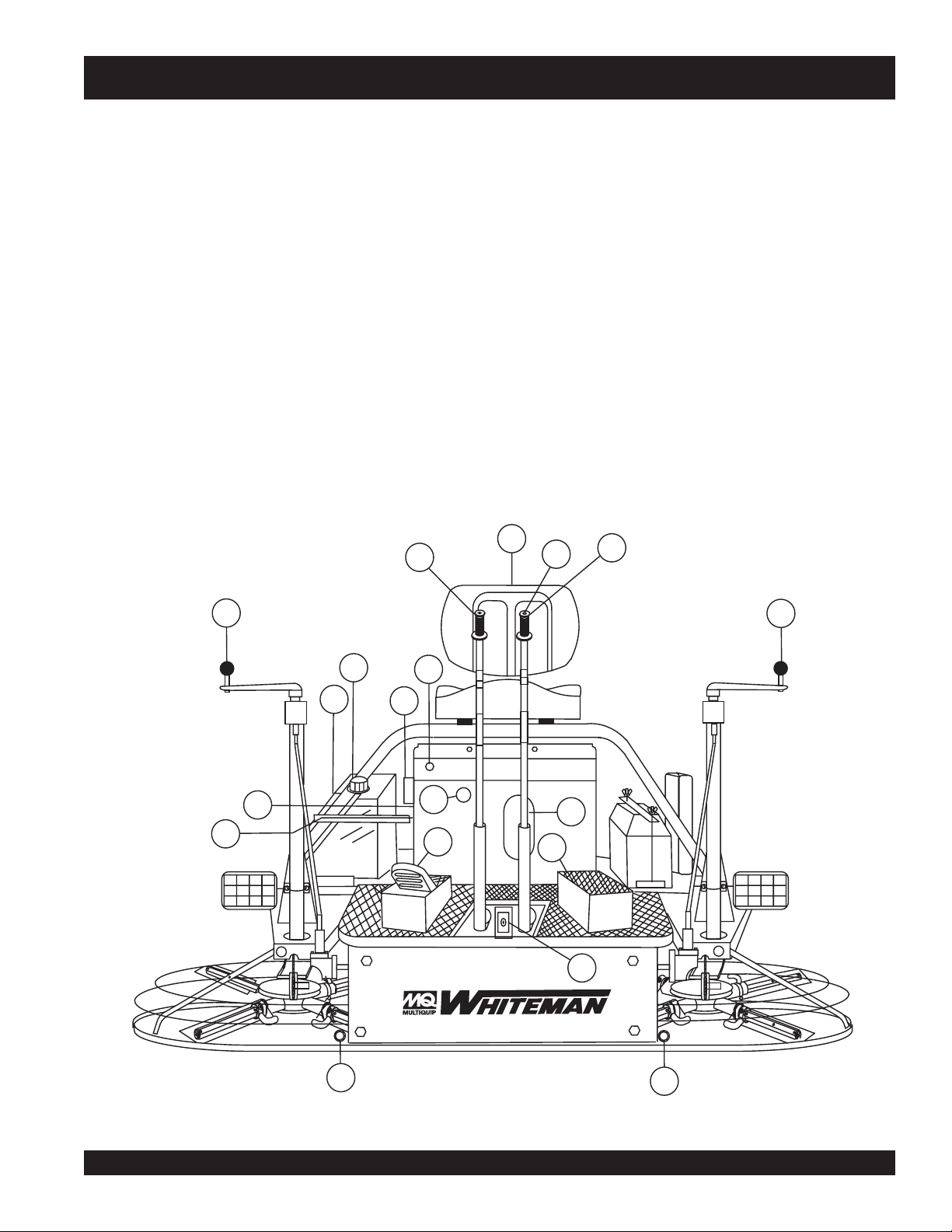
Figures 2 and 3 show the location of the controls, indicators and
general maintenance parts. Each control may perform more than
one function. The functions of each control or indicator is on
pages 16 and 17.
PAGE 16 — HTN 31V
JWN-SERIES • RIDE-ON POWER TROWEL — PARTS AND OPERATION MANUAL — REV. #8 (12/18/07) — PAGE 16
Page 17
JWN-SERIES — CONTROLS AND INDICATORS
1. Seat – Engine will not start unless operator is seated.
2. Steering Control Levers -Directs the unit forward, reverse,
left, or right.
3. Retardant Spray Control Button – Sprays retardant
through the nozzle at the front of the machine.
4. Twin Pitch Control – Both pitch towers are linked together.
One crank may be turned to adjust the blade pitch
simultaneously or individually controlled for each set of
blades. Turn the crank as marked on its top surface to
increase or decrease blade pitch.
5. Light Switch – Turns on three halogen lights. Two in front
one in rear.
6. Ignition Switch – With key inserted, turn clockwise to
start engine.
7. Hour Meter - Indicates number of hours the engine is run.
8. Choke Control Lever - In cold weather pull this lever to
start engine. After engine warms push knob all the way in.
2
9. Fuel Gauge/Filler Cap - Indicates the amount of fuel in
10. Fuel Tank - Holds 5 gallons of unleaded gasoline.
11. Left Foot Riser – Operator foot rest pedal.
12. Spray Nozzle – Spray nozzle for retardant.
13. Right Foot Pedal – Controls blade speed. Slow blade
14. EZ- Mover Boss – Front attachment point for EZ Mover.
15. Dip Stick- Access hole provided to check engine oil.
16. Spark Plug- Access the spark plug through this cutout.
1
the fuel tank. Remove this cap to add fuel.
speed is accomplished by slightly depressing the foot pedal.
Maximum blade speed is accomplished by fully depressing
the foot pedal.
Used to move the trowel.
3
2
4
9
10
7
8
5
6
16
13
15
11
12
4
14
Figure 2. JWN-SERIES Controls and Indicators (Front)
JWN- SERIES • RIDE-ON POWER TROWEL — PARTS AND OPERATION MANUAL — REV. #8 (12/18/07) — PAGE 17
14
Page 18
JWN-SERIES — CONTROLS AND INDICATORS
RETARDANT ONLY
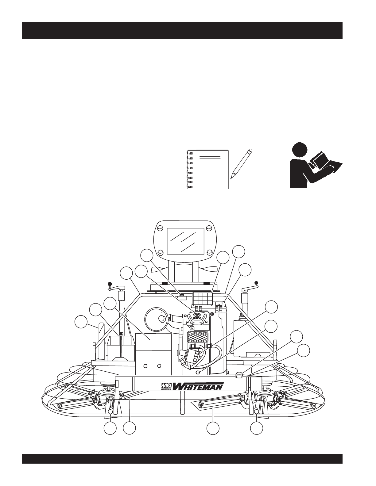
17. Safety "kill switch" – Shuts down engine when seat is
25. EZ- Mover Boss – Rear attachment point for EZ Mover.
empty.
18. Rear Light – The JWN-Series Ride-On Power Trowel has
26. Spiders (Left/Right) – Consists of trowel arms, blades,
three 12 volt halogen lights.
19. Lift Loops – Located on both sides of the main frame.
Used to lift the trowel.
27. Document Box- Contains all product documentation.
28. Battery – Provides +12V DC power to the electrical
20. Engine Air Filter – Protects the engine from dirt.
21. Oil Filter – Filters the engine oil.
29. Belt Guard – Encloses drive belt used in conjunction with
22. Oil Drain - Remove the plug to drain the engine oil.
23. Retardant Spray Tank – Holds 5 gallons of retardant.
30. Engine Oil Fill - Remove this cap to add engine oil.
24. Retardant Spray Pump – Delivers retardant to the spray
nozzle.
Read this entire instruction manual completely before
attempting to operate the trowel.
Used to transport the trowel.
wear plate, and thrust collar.
system.
clutch.
NOTE
27
28
29
25
17
30
19
26
RETARDANT ONLY
26
19
18
20
21
22
23
24
25
Figure 3. JWN-SERIES Controls and Indicators (Rear)
PAGE 18 — HTN 31V
JWN-SERIES • RIDE-ON POWER TROWEL — PARTS AND OPERATION MANUAL — REV. #8 (12/18/07) — PAGE 18
Page 19
JWN-SERIES — BASIC ENGINE
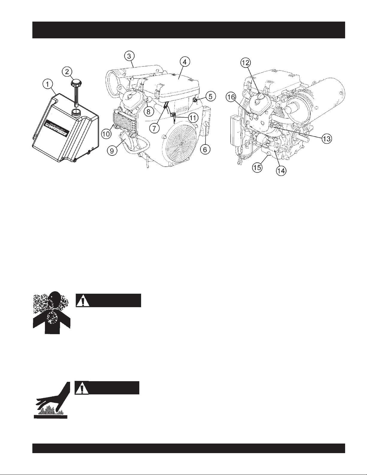
Figure 4. Engine Controls and Components
INITIAL SERVICING
The engine (Figure 4) must be checked for proper lubrication and
filled with fuel prior to operation. Refer to the manufacturer's engine
manual for instructions & details of operation and servicing. The
engine shown above is a HONDA engine. Operation for other
types of engines may vary somewhat.
1. Fuel Tank – Five gallon capacity; use unleaded gasoline.
2. Fuel Filler Cap – Remove this cap to add unleaded
gasoline to the fuel tank. Make sure cap is tightened
securely. DO NOT over fill.
4. Air Filter – Prevents dirt and other debris from entering the
fuel system. Unsnap air filter cover to gain access to filter
element.
5. Choke Knob – Used in the starting of a cold engine or in
cold weather conditions. The choke enriches the fuel
mixture.
6. Engine ON/OFF Switch – "ON" position permits engine
starting, "OFF" position stops engine operations.
7. Fuel Drain Valve – OPEN to let fuel flow, CLOSE to stop
the flow of fuel.
DANGER
Add fuel to the tank only when the engine is
stopped and has had an opportunity to cool down.
In the event of a fuel spill, DO NOT attempt to
start the engine until the fuel residue has been completely wiped up
and the area surrounding the engine is dry.
3. Muffler – Used to reduce noise and emissions.
WARNING
Engine components can generate extreme heat.
To prevent burns, DO NOT touch these areas
while the engine is running or immediately after operating. NEVER
operate the engine with the muffler removed.
JWN- SERIES • RIDE-ON POWER TROWEL — PARTS AND OPERATION MANUAL — REV. #8 (12/18/07) — PAGE 19
8. Fuel Filter – Filters fuel for contaminants.
9. Oil Filter – Spin-on type, filters oil for contaminants.
10. Oil Cooler – Helps keep engine oil cooler for longer engine
life.
11. Throttle Lever – Controlled by accelerator pedal,
increases or decreases engine RPM.
12. Oil Filler Cap – Remove to add engine oil.
13. Oil Dip Stick – Remove to check amount and condition of
oil in crankcase.
14. Starter – Starts engine when ignition key is rotated to the
"ON" position.
15. Oil Drain Plug – Remove to drain crankcase oil.
16. Spark Plug – Provides spark to the ignition system. Set
spark plug gap to 0.6 - 0.7 mm (0.028 - 0.031 inch) Clean
spark plug once a week.
Page 20
JWN-SERIES — NEW MACHINE SETUP INSTRUCTIONS
Trowel Pre-Set Up Instructions
The purpose of this section is to assist the user in setting up a
NEW
trowel. If your trowel is already assembled, (seat, handles,
knobs and battery), this section can be skipped.
The new trowel cannot be put into
service until the pre-setup installation
NOTE
Before packaging and shipping, this JWN SERIES Ride-On
Power Trowel was run and tested at the factory. If there are
problems, please let us know.
Control Handle Assembly
The steering control handles are not attached to the trowel's two
lower handles at the time of shipment. To attach the steering
control handles to the two lower handle assemblies perform the
following:
1. Remove the bolts from the plastic bag tied to the control
towers.
instructions are completed. These
pre-setup instructions only need to
be performed at the time of
NEW
unpacking a
trowel.
Seat Assembly
The seat is not installed on the trowel for shipping purposes. To
attach the seat perform the following:
NOTE
seat. H and S-series trowels have a seat that is mounted
on tracks, similar to an automobile seat. This seat can be adjusted
fore and aft via the control lever under the front of the seat.
1. Remove the seat from the protective wrapping.
2. Remove the bolts on the bottom of the seat, and place seat
on the seat mounting plate, then insert the bolts through
the holes or slots on the seat mounting plate and tighten.
Battery Setup
This trowel was shipped with a wet charged battery. This battery
may need to be charged for a brief period of time as per the
manufacturer instructions.
There are two types of seats,
depending on what type of trowel
you have. J and B series trowels have
slots on the seat mounting plate that
allow fore and aft adjustment of the
2. Remove all protective wrapping and straps from the control
handles.
3. Slip the top (loose) piece into the base of the corresponding
handle, making sure to line up the holes.
4. Install the bolt through the lined up holes and tighten the
acorn nut onto the threaded end.
Some models are equipped with
NOTE
5. Pay close attention to any wires that may be inside the
control handles. DO NOT pinch or cut any wires during
installation.
6. Inside the plastic bag of parts are two knobs for the pitch
control tower cranks. Install these two knobs onto the tower
crank levers.
adjustable height handles. Adjust the
height by placing the bolt through the
set of holes that corresponds to the
most comfortable height.
Use all safety precautions specified by the battery
manufacturer when working with the battery. See further
specific safety information on page 14 of this manual.
To install the battery on the trowel, make sure that the battery is
well seated in the battery box. Connect the positive cable to the
positive terminal on the battery first, then connect the negative
cable to the negative terminal. Close the plastic battery box cover
and secure the battery box.
CAUTIONCAUTION
CAUTION
CAUTIONCAUTION
PAGE 20 — HTN 31V
JWN-SERIES • RIDE-ON POWER TROWEL — PARTS AND OPERATION MANUAL — REV. #8 (12/18/07) — PAGE 20
Page 21
JWN-SERIES — INITIAL START-UP
The following section is intended as a basic guide to the ride-on
trowel operation, and is not to be considered a complete guide
to concrete finishing. It is strongly suggested that all operators
(experienced and novice) read “
the American Concrete Institute, Detroit Michigan.
DO NOT use your ride-on power trowel until this section is
thoroughly understood.
CAUTIONCAUTION
CAUTION
CAUTIONCAUTION
Slabs on Grade
” published by
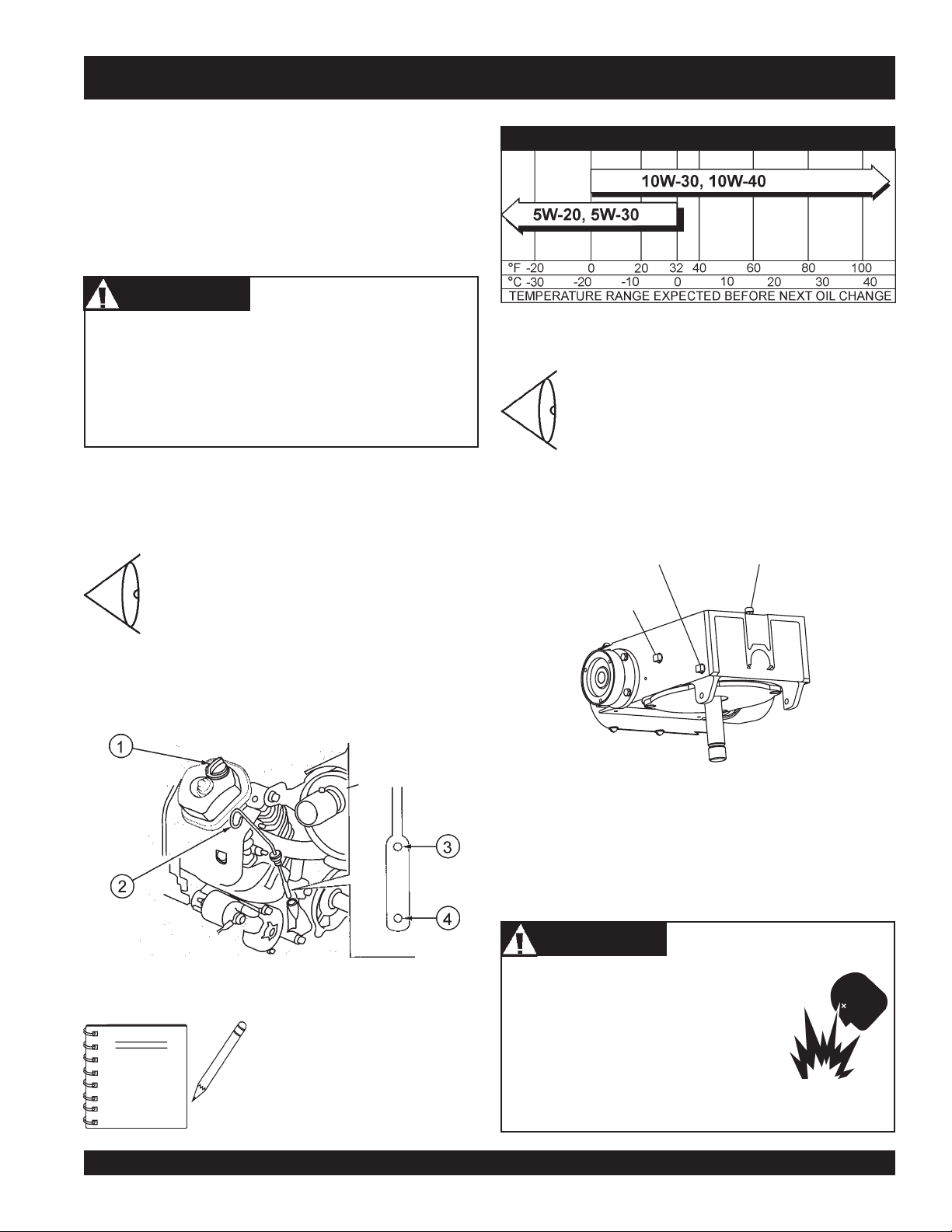
Table 4. Recommended Viscosity Grades
Failure to understand the operation of the JWN-SERIES
trowel could result in severe damage to the machine or
personal injury.
See Figures 2 and 3 (Pages 20 and 21) for the location of
any control or indicator referenced in this manual.
Engine Oil Level
ALWAYS check engine oil BEFORE EACH USE.
1. Pull the engine oil dipstick (Item 2, Figure 5)
from its holder.
2. Determine if engine oil is low (Figure 5).
3. If engine oil is low, remove oil filler cap (Item 1, Figure 5),
and add correct amount of engine oil to bring oil level to a
normal safe level. Use oil as recommeded in Table 3.
Gearbox Oil Level
1. Check the gearbox oil level in both gearboxes
by removing the level plug and ensuring that
the oil is at the correct level. See Figure 6.
2. Fill the gear box just to the level of the fill plug.
(Figure 6) with 69 oz. of Mobil ISO VG 640
SCH 634 oil.
DRAIN
PLUG
FILL/LEVEL
CHECK PLUG
GEARBOX
VENT
Figure 6. Gearbox Oil Plugs/Sight Glass
Fuel
Determine if the engine fuel is low (Figure 7). If fuel level is low,
remove the fuel filler cap and fill with unleaded gasoline.
DANGERDANGER
DANGER
DANGERDANGER
Figure 5. Engine Oil Dipstick
To prevent extensive engine wear or
damage, always maintain the proper
NOTE
JWN- SERIES • RIDE-ON POWER TROWEL — PARTS AND OPERATION MANUAL — REV. #8 (12/18/07) — PAGE 21
oil level in the crankcase. Never
operate the engine with the oil level
outside of marks on dipstick, (Items
3 and 4 in Figure 5.)
Handle fuel safely. Motor fuels are highly
flammable and can be dangerous if
mishandled. DO NOT smoke while
refueling. DO NOT attempt to refuel the ride-
on trowel if the engine is hot or running. DO
NOT attempt to start the engine until the fuel
residue has been completely wiped up and
the area surrounding the engine is dry.
Page 22
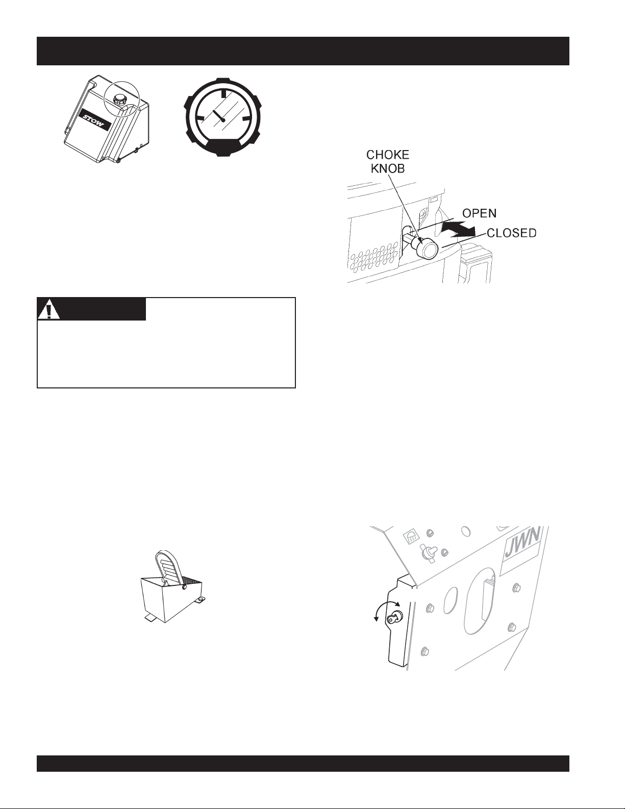
ENGINEFUEL ONLY
SER IES
Figure 7. Fuel Gauge
Important Information Before You Start
FUEL
E
JWN-SERIES — INITIAL START-UP
5. When starting a cold engine, pull the choke knob, (Figure 9)
out to the
engine is warm, the unit can be started with choke halfway
or completely
closed
F
position. In warm weather or when the
open
.
1. This
NEVER disable or disconnect the "safety stop switch". It is
provided for the operator's safety and injury or death may
result if it is disabled, disconnected or improperly
maintained.
2. The safety stop switch should be used to stop the engine
3. The right foot pedal (Figure 8) controls blade and engine
ride-on trowel
switch"
Remember the engine will not start unless an operator is
sitting in the operator’s seat. The weight of an operator
depresses an electrical switch which will allow the engine
to start.
after every use. Doing this will verify the switch is working
properly thus providing safety for the operator. Remember
to turn the key to the “OFF” position after stopping the
machine. Not doing so will drain the battery.
speed. The position of the foot pedal determines the blade
speed. Slow blade speed is obtained by slightly depressing
the pedal. Maximum blade speed is obtained by fully
depressing the pedal.
. This switch is located beneath the seat assembly.
WARNINGWARNING
WARNING
WARNINGWARNING
is equipped with a safety
"safety stop
6. Keep your foot OFF the blade speed control pedal and in
all circumstances, start the engine at idle (without touching
the pedal).
7. Insert the
8. Turn the ignition key (Figure 10) clockwise and listen for
the engine to start. Once the engine starts release ignition
key.
9. If the engine fails to start in this manner, consult the engine
owner's manual supplied with the trowel.
10. Test the safety stop switch by standing up briefly. The switch
under the seat should cause the engine to stop. If the switch
fails to shut down the engine. Turn off the engine with the
key switch and repair the safety stop switch. See Table 6
(Troubleshooting ) for possible causes.
Figure 9. Choke Knob
ignition key
into the ignition switch.
SER IES
START
Figure 8. Blade Speed Control Foot Pedal
Starting the Engine
1. With one foot on the ground and the other foot placed on
the trowel's platform, grab the frame near the seat and lift
yourself onto the trowel. Sit in the operator's seat and ensure
the control handles, foot pedal and control panel items can
be comfortably accessed.
JWN-SERIES • RIDE-ON POWER TROWEL — PARTS AND OPERATION MANUAL — REV. #8 (12/18/07) — PAGE 22
11. Let the engine idle for 3-5 minutes. If choke is applied,
PAGE 22 — HTN 31V
OFF
Figure 10. Ignition Key
push the choke to the open position as soon as the engine
will run smoothly.
Page 23
JWN-SERIES — INITIAL START-UP
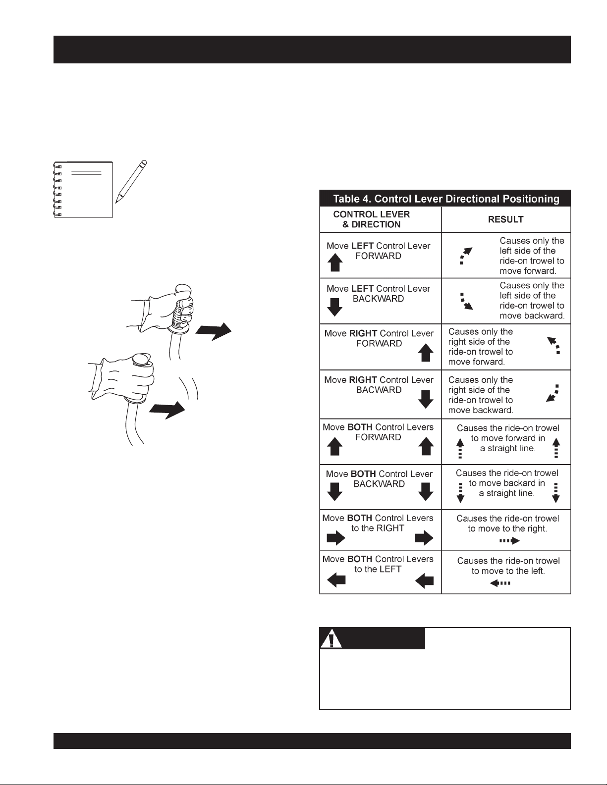
Steering
Two control levers located in front of the operator’s seat provide
directional control for the JWN-SERIES Ride-On Power Trowel.
Table 4 illustrates the various directional positions of the joysticks
and their effect on the ride-on trowel.
NOTE
1. Push both the left and right control levers forward. See
Figure 11.
All directional references with respect
to the steering control levers are from
operator’s
the
LEFT CONTROL LEVER
seat position.
5. Try adjusting the pitch of the blades. This can be done with
the ride-on trowel stopped or while the trowel is moving,
whatever feels comfortable. Test the operation of optional
equipment like retardant spray and lights if equipped.
6. Pull both the left and right joysticks backward and repeat
steps 3 through 6 while substituting the word reverse for
forward.
FORWARD DIRECTION
RIGHT CONTROL LEVER
Figure 11. Left and Right Control Levers
2. With your right foot quickly depress the right foot pedal
halfway. Notice that the ride-on power trowel begins to move
in a forward direction. Return both joystick controls to their
neutral position to stop forward movement, then remove
your right foot from the right foot pedal.
3. Practice holding the machine in one place as you increase
blade speed. When about 75% of maximum blade speed
has been reached, the blades will be moving at proper
finishing speed. The machine may be difficult to keep in
one place. Trying to keep the ride-on trowel stationary is a
good practice for operation.
4. Practice maneuvering the ride-on trowel using the
information listed in Table 4. Try to practice controlled
motions as if you were finishing a slab of concrete. Practice
edging and covering a large area.
Trowel arms can be damaged by rough handling or by
striking exposed plumbing or forms while in operation.
ALWAYS
to the trowel arms.
CAUTIONCAUTION
CAUTION
CAUTIONCAUTION
look-out for objects which might cause damage
JWN- SERIES • RIDE-ON POWER TROWEL — PARTS AND OPERATION MANUAL — REV. #8 (12/18/07) — PAGE 23
Page 24
JWN-SERIES — MAINTENANCE
Maintenance
When performing any maintenance on the trowel or engine,
follow all safety messages and rules for safe operation stated at
the beginning of this manual.
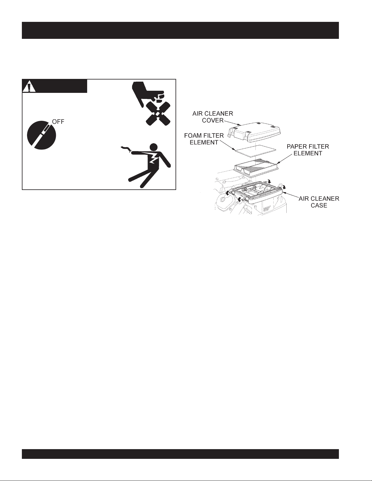
WARNING
Accidental starts can cause severe injury
or death.
ALWAYS place the ON/OFF switch in the
OFF position.
Disconnect and ground spark plug
leads and disconnect negative
battery cable from battery before
servicing.
Maintenance Schedule
1. Check and retighten all fasteners as necessary.
Air Cleaner (Daily)
Thoroughly remove dirt and oil from the engine and control
area. Clean or replace the air cleaner elements as necessary.
Check and retighten all fasteners as necessary.
1. Release the four latch tabs (Figure 12) from the air cleaner
cover, and remove the cover.
Daily (8-10 Hours)
1. Check the fluid levels in the engine and gearboxes, fill as
necessary. Check Air Cleaner. See section on Air Cleaner
servicing.
Weekly (30-40 Hours)
1. Relube arms, thrust collar and steering links.
2. Replace blades if necessary.
3. Check and clean or replace the engine air filter as
necessary. (See following section on Air Filter
Maintenance.)
4. Replace engine oil and filter as necessary. (See following
section on Oil and Filter.)
Monthly (100-125 Hours)
1. Remove, clean, reinstall and relube the arms and thrust
collar. Adjust the blade arms.
2. Replace gearbox lubricant after the first 100 hours of
operation. Replace every 500-600 hours thereafter.
3. Check drive belt for excessive wear. (Refer to following
section on Drive Belt maintenance.)
Yearly (500-600 Hours)
1. Check and replace if necessary the arm bushings, and
thrust collar bushings, shaft seals and belts.
2. Check pitch control cables for wear.
2. Remove the foam filter from the cover.
3. Remove the paper filter from the air cleaner case.
4. Inspect both air filter elements, replace them if necessary.
5. To clean the paper air filter, tap the filter element several
times on a hard surface to remove dirt, or blow compressed
air (not to exceed 30 psi (207 kPa, 2.1 kgf/cm
filter element from the air cleaner case side.
6.
NEVER!
fibers. If the paper element is excessively dirt, replace
element.
7. Clean the
rinse and allow to dry thoroughly. Or clean with a
nonflammable solvent and allow to dry. DO NOT pour any
type of oil into the foam element.
8. Wipe dirt from the inside of the air cleaner body and cover,
using a moist cloth. Be careful not to let any dirt or debris to
enter the air chamber that leads to the carburetor.
9. Reinstall the foam air filter element to the air cleaner cover,
then reinstall the paper air filter element and cover to the
air cleaner case. Securely latch the four hook tabs on the
air cleaner cover
Figure 12. Air Cleaner Components
2
) through the
try to brush off dirt; brushing will force dirt into the
foam air filter element
in warm soapy water,
3. Replace gearbox lubricant.
JWN-SERIES • RIDE-ON POWER TROWEL — PARTS AND OPERATION MANUAL — REV. #8 (12/18/07) — PAGE 24
PAGE 24 — HTN 31V
Page 25
Oil And Fuel Lines
CAUTIONCAUTION
CAUTION
CAUTIONCAUTION
Operating the engine with a blocked grass screen, dirty or
plugged cooling fins, and/or cooling shrouds removed, will
cause engine damage due to overheating.
■
Check the oil and fuel lines and connections regularly for
leaks or damage. Repair or replace as necessary.
■
Replace the oil and fuel lines every two years to maintain the
line's performance and flexibility.
JWN-SERIES — MAINTENANCE
Changing Engine Oil (100 Hours)
1. Change the engine oil after the first 20 hours of use, then
change every 6 months or 100 hours.
2. Remove the oil filler cap (Figure 5, Item 1), and fill engine
crankcase with recommended type oil as listed in Table 4.
Fill to the upper limit of dipstick.
3. Crankcase oil capacity is 1.69 qts. (1.60 liters) without oil
filter replacement, with oil filter replacement 2.02 qts. (1.90
liters).
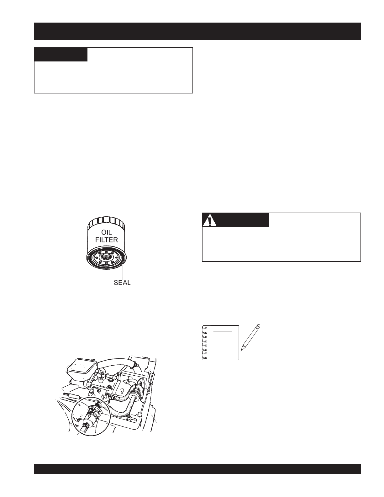
Oil Filter (200 Hours)
1. Replace the engine oil filter (Figure 13) every 200 hours.
Long Term Storage
■
Remove the battery.
■
Drain fuel from fuel tank, fuel line and carburetor.
■
Remove spark plug and pour a few drops of motor oil into
cylinder. Crank engine 3 to 4 times so that oil reaches all
internal parts.
■
Clean exterior with a cloth soaked in clean oil.
■
Store unit covered with plastic sheet in moisture and dustfree location out of direct sunlight.
Never store the ride-on trowel with fuel in the tank for any
extended period of time. Always clean up spilled fuel
immediately.
Engine Tune-Up
CAUTIONCAUTION
CAUTION
CAUTIONCAUTION
Figure 13. Oil FIlter
2. Be sure to coat the
engine oil.
Fuel Filter (200 Hours)
1. Replace the engine fuel filter (Figure 14) every 200 hours.
Figure 14. Honda Fuel Filter
JWN- SERIES • RIDE-ON POWER TROWEL — PARTS AND OPERATION MANUAL — REV. #8 (12/18/07) — PAGE 25
seal
of the new oil filter with clean
■
See your engine manual for specific information on tuning
up your engine, checking and gaping the spark plugs, etc.
See the engine manual supplied with
NOTE
At the front of the book (Page 9) there is a “Daily Pre-Operation
Checklist”. Make copies of this checklist and use it on a daily
basis.
Disconnect spark plug wires and battery cables before attempting
any service or maintenance on the ride-on trowel.
your machine for appropriate engine
maintenance schedule and
troubleshooting guide for problems.
Page 26
JWN-SERIES — MAINTENANCE
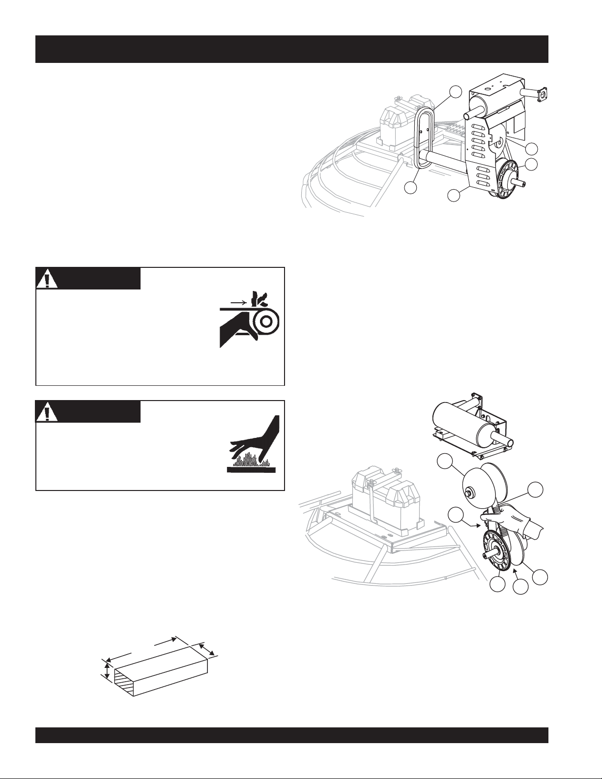
Checking The Drive Belt
The drive belt needs to be replaced as soon as it starts to show
signs of wear. Indications of excessive belt wear are fraying,
squealing when in use, belts that emit smoke or a burning rubber
smell when in use.
5
Under normal operating conditions, a drive belt may last
approximately 150 hours. If your trowel is not reaching this kind
of life span for drive belt wear, check the drive belt for proper
pulley alignment and spacing.
To gain access to the drive belt, remove the drive belt guard
cover (Item 1, Figure 16), then visually inspect the drive belt for
signs of damage or excessive wear. If the drive belt is worn or
damaged, replace the drive belt.
WARNINGWARNING
WARNING
WARNINGWARNING
DO NOT attempt to insert hands or tools
into the belt area while the engine is
running. NEVER run the engine with the
safety guards removed. Keep fingers,
hands, hair and clothing away from all
moving parts to prevent bodily injury.
WARNINGWARNING
WARNING
WARNINGWARNING
1. Remove Drive Belt Guard Cover (Item 1, Figure 16).
2. Squeeze the drive belt as shown in Figure 17, and pull the
V-belt upwards. This will spread open the faces of the
drive pulley.
3
2
4
1
1 Drive Belt Guard Cover
2 Lower Pulley
3 Upper Pulley
4 Spare Drive Belt
5 Spare Drive Belt Holder
Figure 16. Drive Belt Guard Cover
lower
DO NOT remove the drive belt guard cover
until the muffler has cooled. Allow the entire
trowel to cool down before performing this
procedure.
Removing the Drive Belt
zz
z
Leave the existing drive belt intact until instructed to cut it.
zz
zz
z
Leave the engine in place for this procedure. It is not
zz
necessary to slide the engine to replace the drive belt.
zz
z
Have a 3/4 X 1 X 3-1/4 inch wooden block available.
zz
WOODEN BLOCK
LENGTH
HEIGHT
.75 IN.
Figure 15. Wooden Block For Spacer Figure 17. Expanding Lower Drive Pulley
JWN-SERIES • RIDE-ON POWER TROWEL — PARTS AND OPERATION MANUAL — REV. #8 (12/18/07) — PAGE 26
3.25 IN.
WIDTH
1.00 IN.
PAGE 26 — HTN 31V
1 Upper Pulley
2 Drive Belt
3 Lower Pulley Fixed Face
4 Lower Pulley Spread Apart
5 Lower Pulley Movable Face
6 Squeeze and Pull Up To Spread
Lower Pulley
1
2
6
5
3
4
Page 27
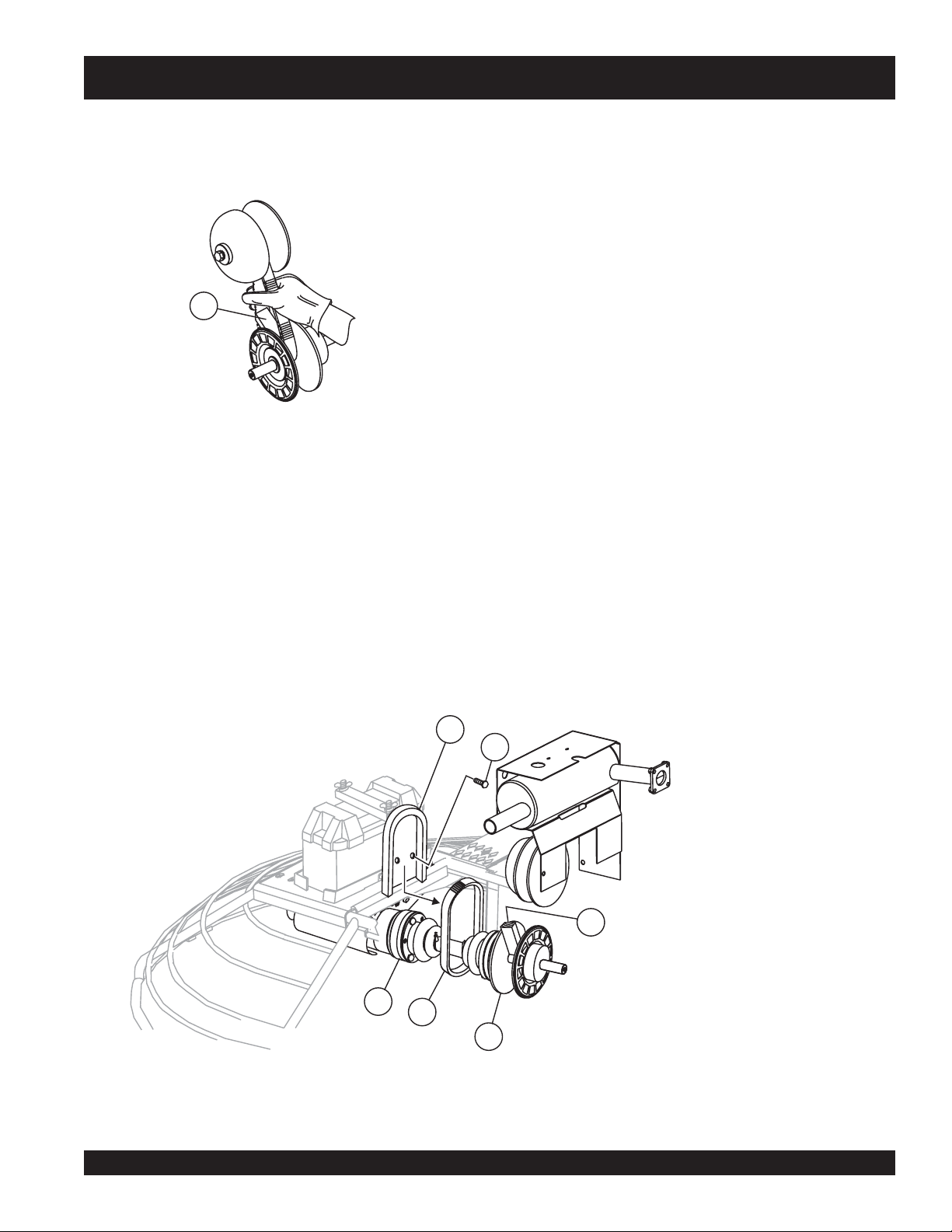
Insert
3.
the 3/4" X 1" X 3-1/4" block between the moveable
face and the fixed face of the lower drive pulley. See Figure
18. This block will help keep the lower drive pulley faces
open while installing the new drive belt.
1
Wooden Block
Figure 18. Holding Lower Pulley Open
4. If the belt is not being reused (recommended),
drive belt. Ensure all belt remnants are removed from the
pulleys.
CUT
the
JWN-SERIES— MAINTENANCE
In the event of a drive belt failure, the spare (replacement) drive belt
can be used for quick replacement at the job site to continue trowel
operation.
1. If necessary, refer to Removing Drive Belt Instructions.
Ensure all remnants of old belt have been removed from
pulleys.
2. To replace the drive belt with the spare drive belt, remove
the 2 bolts that secure the drive belt carrier. (Figure 19)
This will allow free movement of the belt for installation.
Take care with to not contaminate the relplacement belt
with grease or dirt.
3. With the 3/4 x 1 x 3-1/4 wood block holding the lower pulley
open, place the replacement belt into the lower pulley first.
Work the belt over the upper drive pulley into the pulley
groove.
4. Squeeze the belt enough to remove the wood block. With
the block removed, release the tension on the belt.
5. Reinstall the spare belt carrier and the drive belt guard.
6. Replace the spare belt before the next trowel use. See
spare drive belt replacement procedures.
Installing the Drive Belt (Using Replacement Drive Belt)
The JWN-SERIES Ride-On Power Trowel is equipped with a
replacement drive belt (spare) carrier, which is mounted on the
inboard side of the fuel tank near the clutch. Make sure that there is
ALWAYS a spare drive belt in the drive belt carrier before the trowel
is placed on a slab to finish concrete.
2
1
4
5
6
Figure 19. Drive Belt Install
3
1 Bolt, Spare Drive Belt Carrier
2 Spare Drive Belt Holder
3 Wooden Block
4 CV-Joint
5 New Spare Drive Belt
6
Lower Drive Pulley
JWN- SERIES • RIDE-ON POWER TROWEL — PARTS AND OPERATION MANUAL — REV. #8 (12/18/07) — PAGE 27
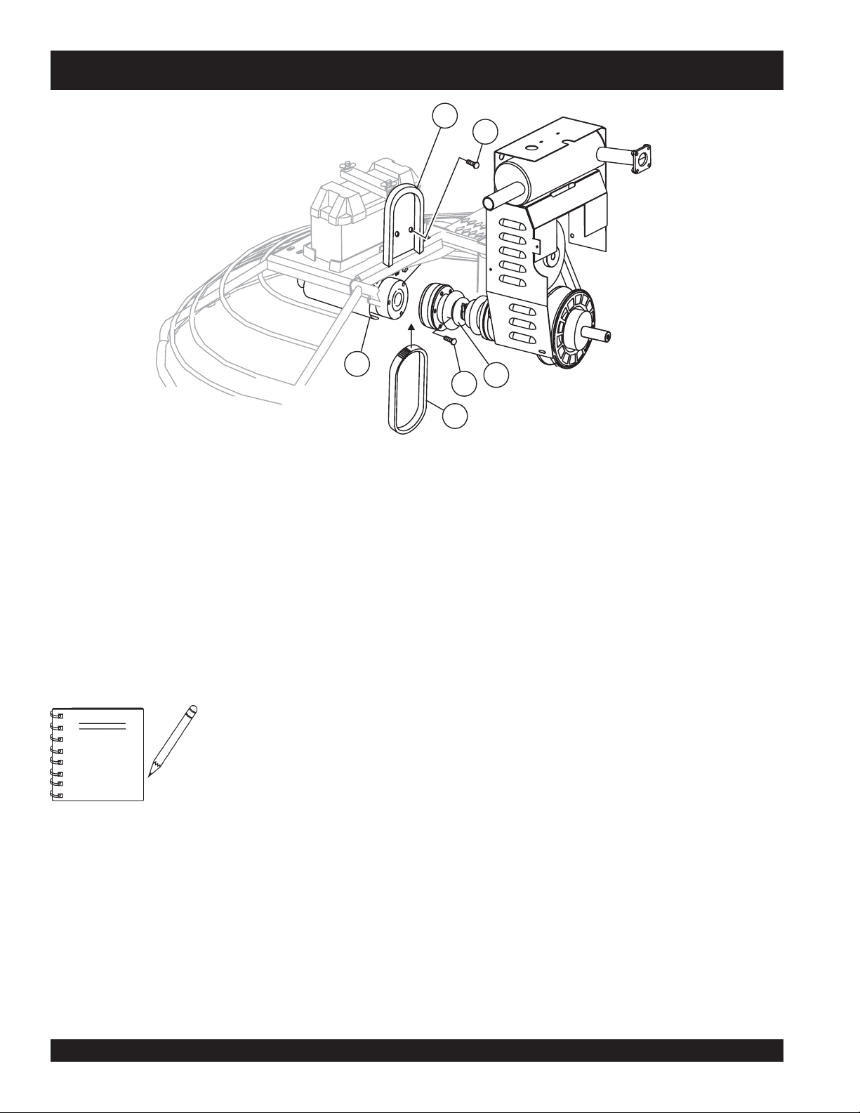
Page 28
JWN-SERIES— MAINTENANCE
5
4
6
2
3
1 CV Joint
2 Bolt (Remove 3 places)
3 New Spare Drive Belt
4 Bolt, Spare Drive Belt Carrier
5 Spare Drive Belt Holder
6 Left Side Gearbox
Figure 20. Spare Drive Belt Replacement
Spare Drive Belt Replacement
It will be necessary to disconnect the
CV-Joint from the left-side gearbox
NOTE
To replace a spare drive belt, be prepared to disconnect the CVjoint from the left-side gearbox. See Figure 20.
1. Place the trowel on suitable supports and observe all safety
precautions.
2. Remove the three screws that secure the CV-joint to the
left-side gearbox coupler.
coupler. This means the removal of
the three screws that secure the CVJoint to the gearbox.
3. Once the CV-joint has been separated from the left-side
gearbox, push the CV-joint inward so that a gap exists
between the gearbox and the CV-joint (Figure 20). Slide
the spare V-belt between the gearbox coupler and the CVjoint. Avoid contaminating the replacement belt with grease
or oil when sliding it between the CV-Joint and gearbox
coupler.
4. Place the spare drive belt inside the drive belt carrier, and
secure the spare belt carrier to the inboard side of the left
gearbox.
5. Install the three screws that secure the CV-joint to the leftside gearbox coupler.
1
PAGE 28 — HTN 31V
JWN-SERIES • RIDE-ON POWER TROWEL — PARTS AND OPERATION MANUAL — REV. #8 (12/18/07) — PAGE 28
Page 29
NEUTRALLOWSPEED HIGHSPEED
DRIVE
PULLEY
DRIVEN
PULLEY
A
B
C
JWN-SERIES— MAINTENANCE
(
)
DRIVE
PULLEY
DRIVE
PULLEY
LOW OUTPUT
SPEED
DRIVEN PULLEY
LOWENGINE RPM
HIGHENGINE RPM
DRIVEN PULLEY
HIGH OUTPUT
SPEED
CENTRIFUGAL FORCE
DISTANCE
MOVEABLE
FACE
TRAVELS
MOVEABLEFACE
IS CONTROLLED
BY ASPRING
AND BELT T ENSION
MOV ABLEFACEIS
CONTROLLED BY
ROLLER WEIGHT ARMS
AND SPRINGS
WEIGHT
RAMP
PLATE
BUSHING
ROLLER ARM
SPRING
DRIVE PULLEY
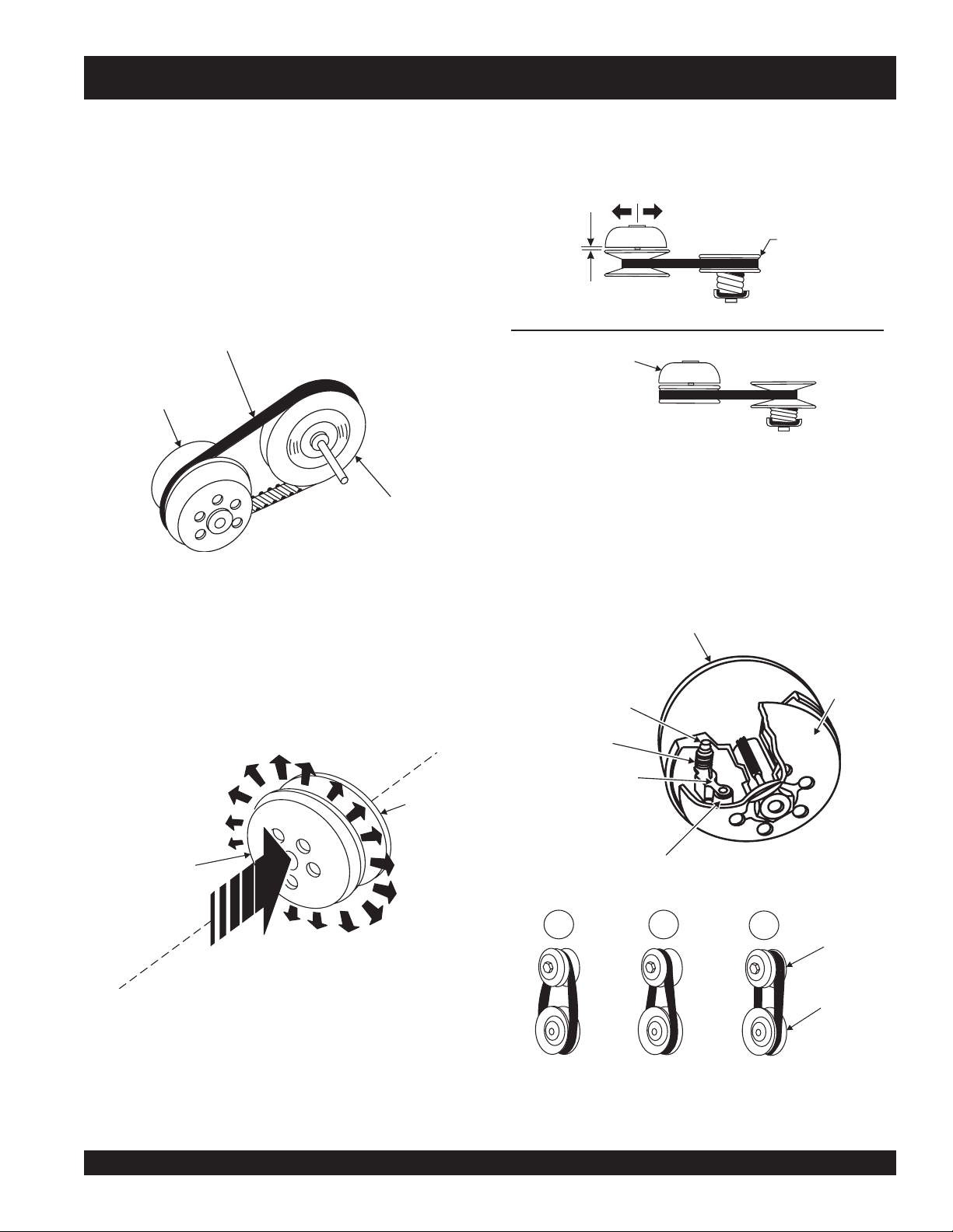
The JWN-Series Ride-On Power Trowel is equipped with a "Torque
Converter" which supplies torque to both the left and right gearboxes.
The function of the torque converter is to automatically deliver the
As shown in Figure 23, centrifugal force pushes the roller arms (see
Figure 23 below) against the ramp plate, forcing moveable face
toward fixed face squeezing belt.
correct amount of torque required by the trowel under all load
conditions. This enables the trowel to deliver the necessary torque
for float pan applications and the high rotor speeds required for
burnishing concrete.
The torque converter used in the JWN Series Ride-On Power Trowel
is a variable pitch pulley type (Figure 21) connected by a drive belt.
DRIVE V-BELT
TORQUE
CONVERTER
VARIABLE PITCH
PULLEY
The "Variable Pitch Pulleys" have one
. The
face
is controlled by roller weight arms and springs, which change
position according to engine speed. The
Fig. 21. Torque Converter/Variable Pitch Pulley
is controlled by a spring and belt tension.
face
Fig. 23. Pulley Interaction
fixed face
drive
pulley ( torque converter, Figure 24) moveable face
, and one
driven
pulley
moveable
moveable
Drive Pulley
The "Drive Pulley" uses centrifugal force (Figures 22 and 23)
to create a belt squeeze force transmitted at the pulley faces.
This condition functions as an automatic clutch.
I
R
F
U
T
N
E
C
VARIABLE
FACE
Figure 22. Torque Converter (Centrifugal Force)
FORCE
BELT SQUEEZE
TORQUECONVERTER
G
A
L
F
O
R
C
DRIVE PULLEY
E
FIXED
FACE
Fig. 24. Variable Pitch Pulley
Figure 25. Pulley Conditions
JWN- SERIES • RIDE-ON POWER TROWEL — PARTS AND OPERATION MANUAL — REV. #8 (12/18/07) — PAGE 29
Page 30
JWN-SERIES— MAINTENANCE
How It Works (Figure 24)
Condition A:
Condition B:
Condition C:
zz
z
Engine Idling
zz
zz
z
Drive Pulley: Small
zz
zz
z
Driven Pulley: Large
zz
zz
z
Belt: Loose and Stationary
zz
zz
z
Engine Accelerating
zz
zz
z
Drive Pulley: Small But Increasing
zz
zz
z
Driven Pulley: Large But Decreasing
zz
zz
z
Belt: Approaching Tightness
zz
zz
Engine At High Speed
z
zz
zz
z
Drive Pulley: Large
zz
zz
z
Driven Pulley: Small
zz
zz
z
Belt: Tight
zz
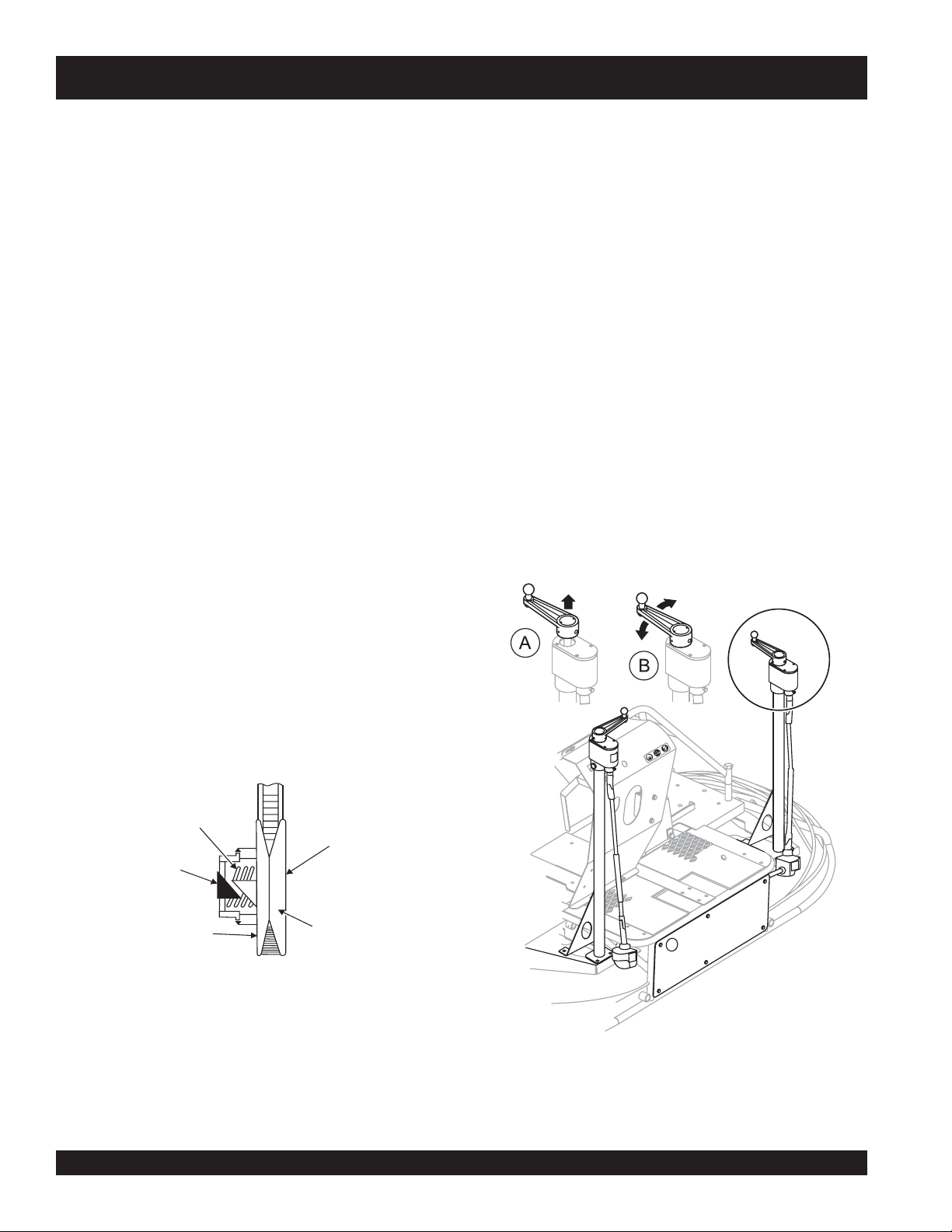
Blade Pitch
Sometimes it may be necessary to match blade pitch between
the two sets of blades. There are some signs that this may be
necessary. For example, the differences in pitch could cause a
noticeable difference in finish quality between the two sets of
blades. Or, the difference in blade pitch could make the machine
difficult to control. This is due to the surface area in contact with
the concrete (the blade set with the greater contact area tends to
stick to the concrete more).
Matching Blade Pitch for Both Sets of Blades
Trowels equipped with optional Twin Pitch
to have blade pitch between the two sets of blades "syncronized".
If the blades need to be syncronized this is easily accomplished
by performing the following. Refer to Figure 27.
1. Lift the pitch adjustment handle on either side. Once lifted,
that side is now disconnected from the Twin Pitch
Clutch
This clutch system provides a high pulley ratio (a low gear- so to
speak) to start out and a low pulley ratio ( a high gear- so to
2. Adjust to match the opposite side.
3. When adjusted, lower the handle to Twin Pitch
position.
speak) for a high speed operation, with infinite variation between
the two.
TM
Controls may need
TM
system.
TM
operating
This means that it will not be necessary to give
full throttle
in
order to "break the blades/pans loose". The machine can slowly
be brought up to speed.
The torque sensitive pulley (Figure 25) utilizes a spring and cam
bracket. Peak performance results from proper interaction between
the driven pulley spring and the ramp angle of the cam bracket.
SPRING
DRIVEN PULLEY
CAM
BRACKET
MOVEABLE
FACE
Figure 26 . Pulley Spring and Cam Bracket
FIXED FACE
A Twin Pitch
TM
disengaged (one side)
B Operating Position
Figure 27. Pitch Towers
PAGE 30 — HTN 31V
JWN-SERIES • RIDE-ON POWER TROWEL — PARTS AND OPERATION MANUAL — REV. #8 (12/18/07) — PAGE 30
Page 31

JWN-SERIES TROWEL — MAINTENANCE
Trowel Arm adjustment Procedure
Figure 29 illustrates the "
(as shipped from the factory).
The following procedure should be
NOTE
followed to adjust trowel arms when
it becomes apparent that the trowel
is finishing poorly or in need of
routine maintenance.
level
, clean area to test the trowel prior to and after adjustement
A
spots
is essential. Any unlevel
in the floor or debris under the
trowel blades will give an incorrect perception of adjustment.
flat
Ideally, a 5' x 5' three-quarter inch thick
steel plate should be
used for testing.
1. To determine which blades need adjustment, place the
trowel in the test area (three-quarter inch thick plate) and look
for the following conditions:
2. Start engine, and bring trowel blades up to full speed and look
for the following conditions:
■
Does the trowel have a perceived rolling or bouncing
motion?
■
Does the guard ring “rock up and down” relative to the
ground?
■
Pitch the blades as flat as possible and look at the
adjustment bolts
with the
lower wear plate
. They should all barely make contact
on the spider. If you can see
Stabilizer Ring Removal
that one of them is not making contact, some adjustment
will be necessary.
■
Is the machine wearing out blades unevenly (i.e. one
1. If the trowel is equipped with an outer stabilizer ring (Figure
30), remove the four bolts at the end of each spider arm.
blade is completely worn out while the others look new)?
correct alignment
" for a spider plate
Figure 29. Correct Spider Plate Alignment
STABILIZER
RING
Figure 28 illustrates "
". Check to see that adjustment bolt is barely touching (0.10"
arms
worn spider bushings or bent trowel
max. clearance) lower wear plate. All alignment bolts should be
spaced the same distance from the lower wear plate.
REMOVE
TO FREE
SPIDER
ASSEMBLY
Figure 28. Worn Arm Bushings
2. Examine stabilizer ring for out of round or bends. If ring is
damaged, replace ring. If ring is found to be correct with no
damage, set aside.
Figure 30 Stabilizer Ring
JWN- SERIES • RIDE-ON POWER TROWEL — PARTS AND OPERATION MANUAL — REV. #8 (12/18/07) — PAGE 31
Page 32

JWN-SERIES TROWEL — MAINTENANCE
Trowel Arm Removal
1. Each trowel arm is held in place at the spider plate by a hex
head bolt (with zerk grease fitting). Remove the hex head
bolt/zerk grease fitting from the spider plate. (Figure 31)
2. Remove the trowel arm from the spider plate.
1 Spider Plate
2 Hex Head Bolt (Zerk Fitting)
Figure 31. Removing Zerk Grease Fitting
Trowel Blade Removal
1. Remove the trowel blades from the trowel arm by removing
the three hex head bolts (Figure 33) from the trowel arm. Set
blades aside.
Wire brush
2.
trowel arm. Repeat this for the remaining three arms.
Figure 33. Trowel Blades
any build-up of concrete from all six sides of the
3. Should the trowel arm inserts (bronze bushing ) come out
with the trowel arm, remove the bushing from the trowel arm
and set aside in a safe place. If the bushing is retained inside
the spider plate, carefully remove the bushing.
4. Examine the bronze trowel arm bushing insert (Figure 32),
clean if necessary. Replace bushing if out-of-round or worn.
Figure 32. Bronze Bushings
PAGE 32 — HTN 31V
JWN-SERIES • RIDE-ON POWER TROWEL — PARTS AND OPERATION MANUAL — REV. #8 (12/18/07) — PAGE 32
Page 33

JWN-SERIES TROWEL — MAINTENANCE
Checking Trowel Arm Straightness
Trowel arms can be damaged by rough handling, (such as dropping
the trowel on the pad), or by striking exposed plumbing, forms, or
rebar while in operation. A bent trowel arm will not allow the trowel
to operate in a smooth fluid rotation. If bent trowel arms are suspect,
check for flatness as follows, refer to Figures 34 and 35.
1 Trowel Arm Round Shaft Section
2 Trowel Arm Hexagonal (Hex) Shaft Section
3 Lever Mounting Slot (Left Arm Shown)
4 Roll Pin Hole
5 Blade Attachment Bolt Hole (One of Three)
6 Flat of Hexagonal Shaft (Top of Arm)
Figure 34. Trowel Arm
3. Next, check the clearance between the round shaft and the
test surface as one of the flat hex sections of the arm rests on
the test surface. Rotate the arm to each of the flat hex sections
and check the clearance of the round shaft. Use a feeler
gauge of .005" (0.127 mm). Each section should have the
same clearance
and the test surface.
4. If the trowel arm is found to be
trowel arm.
Trowel Arm Adjustment
Shown in (Figure 38) is the adjustment fixture with a trowel arm
inserted. As each trowel arm is locked into the fixture, the arm bolt
is adjusted to where it contacts a stop on the fixture. This will
consistently adjust all of the trowel arms, keeping the finisher as
flat and evenly pitched as possible.
1. Locate the trowel arm adjustment tool P/N 9177.
between the round of the trowel arm shaft
uneven
or
bent
, replace the
1
1. Use a thick steel plate, granite slab or any surface which is
true
and
flat
, to check all
flatness.
2. Check each of the six sides of the trowel arm (hex section).
A feeler gauge of .004" (0.10 mm) should not pass between
the flat of the trowel arm and the test surface along its length
on the test surface. (Figure 35, Item 3) .
1 Trowel Arm
2 Flat Test Surface
3 Feeler Gauge (.004 in. / 0.10 mm)
4 Feeler Gauge (.005 in. / 0.127 mm))
Figure 35. Checking Trowel Arm Flatness
six sides
of each trowel arm for
Figure 36. Trowel Arm Adjustment Tool Side View
2. Ensure the fixture arm is in the proper setting (up or down) for
your trowel arm rotation as shown in Figure 37.
NOTE
3
2
4
SIDE VIEW
1 Adjustment Bolt
2 "Distance"
3 Locking Nut
4 Fixture Arm
Arms with CLOCK-WISE blade
rotation use the fixture arm in the UP
position (A in Figure 37). Arms with
COUNTER CLOCK-WISE blade
rotation use the fixture with the fixture
arm in the DOWN position. (B in Figure
37).
JWN- SERIES • RIDE-ON POWER TROWEL — PARTS AND OPERATION MANUAL — REV. #8 (12/18/07) — PAGE 33
Page 34

JWN-SERIES TROWEL — MAINTENANCE
4. Use an allen wrench to tighten the locking bolts securing the
trowel arm in place.
5. Adjust the bolt "distance" shown in Figure 36 to match one
of the arms. The other arms will be adjusted to match this
distance.
6. Loosen the locking nut on the trowel arm lever, then turn the
trowel arm adjusting bolt until it barely touches (.010") the
fixture adjusting bolt.
7. Once the correct adjustment is made, tighten the lock nut on
the trowel arm to lock in place.
8. Loosen locking nuts on the adjustment fixture, and remove
Figure 37. Trowel Arm Adjustment Setup
3. Unscrew the locking bolts on the adjustment tool and place
the trowel arm into the fixture channel as shown in Figure 38
A thin shim may be required to cover the blade holes on the
trowel arm. Make sure to align the trowel adjustment bolt with
the fixture adjustment bolt.
trowel arm.
9. Repeat steps for the remaining trowel arms.
Re-Assembly
1. Clean and examine the upper/lower wear plates and thrust
collar. Examine the entire spider assembly. Wire brush any
concrete or rust build-up. If any of the spider components are
found to be damaged or out of round, replace them.
2. Make sure that the bronze trowel arm bushing is not damage
3. Reinstall bronze bushing onto trowel arm.
4. Repeat steps 2 -3 for each trowel arm.
5. Make sure that the spring tensioner is in the correct position
6. Insert all trowel arms with levers into spider plate (with bronze
1 Arm
2 Trowel Arm Lever
3 Fixture Arm
4 Adjustment Bolt
5 Distance = .010 Inch
6 Adjustment Bolt
7 Trowel Arm Adjustment Fixture
8 Locking Bolts
9 Shim
Figure 38. Trowel Arm Adjustment Fixture Components
7. Lock trowel arms in place by tightening the hex head bolt with
8. Re-install the blades onto the trowel arms.
9. Install stabilizer ring onto spider assembly.
10. Lubricate all grease points (zerk fittings) with premium
or out of round. Clean the bushing if necessary. If the bronze
bushing is damaged or worn, replace it.
to exert tension on the trowel arm.
bushing already installed) using care to align grease hole on
bronze bushing with grease hole fitting on spider plate.
zerk grease fitting and jam nut.
Lithum 12"
"
consistency.
based grease, conforming to NLG1 Grade #2
PAGE 34 — HTN 31V
JWN-SERIES • RIDE-ON POWER TROWEL — PARTS AND OPERATION MANUAL — REV. #8 (12/18/07) — PAGE 34
Page 35

JWN-SERIES TROWEL — MAINTENANCE
Installing Pans Onto Finisher Blades 1. Lift trowel just enough to slide pan under blades. Lower
These round discs sometimes referred to as "pans" attach to the
spiders arms and allow early floating on wet concrete and easy
movement from wet to dry areas. They are also very effective in
embedding large aggregates and surface hardeners.
WARNINGWARNING
WARNING
WARNINGWARNING
ALWAYS install pans either on the work area or on an area
that is next to and level with the work area. DO NOT lift the
trowel when the pans are attached.
Refer to Figure 39 when installing pans onto finisher blades.
finisher onto pan with blades (Item #1) adjacent to Z-Clips
(Item #4).
2. Rotate blades into position under Z-Clips. Ensure that the
blades are rotated in the direction of travel when the machine
is in operation or use the engine to rotate the blades into
position.
3. Attach the blade tie-downs (Item #3) to the far side of the Z-
Clip brackets (Item #4) with tie-down knobs (Item #2) as
shown in figure 39.
4. Check to make certain that the blade edges are secured
under the Z-Clips and the tie-downs are secured completely
over the edges of the blade bar before the machine is put back
into operation.
Decommissioning Trowel/Components
Decommissioning is a controlled process used to safely retire a
piece of equipment that is no longer serviceable. If the equipment
poses an
or damage or is no longer cost effective to maintain, (beyond lifecycle reliability) and is to be decommissioned,
dismantlement), the following procedure must take place:
unacceptable and unrepairable safety risk due to wear
(demolition and
2
4
1 BLADE ASSEMBLY
2 KNOB, TIE-DOWN Z-CLIP PANS
3 TIE-DOWN, BLADE
4 Z-CLIP, PAN
Figure 39. Z-Clip Finisher Pan Installation
1. Drain all fluids completely. These may include oil, gasoline,
hydraulic oil and antifreeze. Dispose of properly in accordance with local and governmental regulations. Never pour
on ground or dump down drains or
sewers.
3
2. Remove battery and bring to appropriate facility for lead
reclamation. Use safety precautions when handling batteries that contain sulfuric acid, (See page 14).
3. The remainder can be brought to a salvage yard or metal
reclamation facility for further dismantling.
1
JWN- SERIES • RIDE-ON POWER TROWEL — PARTS AND OPERATION MANUAL — REV. #8 (12/18/07) — PAGE 35
Page 36

JWN-SERIES TROWEL — TROUBLESHOOTING (ENGINE)
GNITOOHSELBUORTENIGNE.5ELBAT
MOTPMYS MELBORPELBISSOP NOITULOS
.ytpmesiknatleuF .knatleuflliF
.desolcsievlavffo-tuhS .evlavffo-tuhsleufnepO
rokaelnoitcussahenilleuF
leufro,retlifleuF.detcirtsersi
.detcurtsbositnevpacknat
.detanimatnocsiylppusleuF htiwlliferdnaknatnaelc,knatleufnaelcdnaniarD
tuBsknarCenignE
tratStoNlliW
.detcennocsid
hctiwspotsytefaS
.noitnuflam
.ytpmesiknatleuF .knatleuflliF
tuBstratSenignE
eunitnoCtoNlliW
gninnuR
.dekcolbsitnev
siroterubrac,deterubracfI
.dekohcrevorodekohcrednu
,deluofsigulpkrapS
ro,deppagylreporpmi
sdaelgulpkrapS.degamad
.desolcsievlavffo-tuhS .evlavffo-tuhsleufnepO
rokaelnoitcussahenilleuF
siretlifleuF.detcirtsersi
packnatleufro,detcurtsbo
.leuf
.rehtaewmraw
.yrassecensa
.detcennocsid
.yrassecen
cenfiecalperdnanoitcirtserrof
cenfiecalperdnanoitcirtserrof
.spmalcenilleufdnanoitidnocenilleufkcehC
retlifleufkcehC.dekniktonsienilleuftahterusnE
leufkcehC.yrasse
.yrassecensaecalperronaelcdnatnevpac
dnadlocrofekohcfotnuomadednemmocerylppA
dna,pagkcehc,gniluofrofgulpkrapskcehC
gulpkrapsecalperronaelC.egamadroftcepsni
fisdaelgulpkrapshcattaeR
gninoitcnufsihctiwSpotSytefaSehttahterusnE
fihctiwsecalper;detaessirotarepoehtnehw
.spmalcenilleufdnanoitidnocenilleufkcehC
retlifleufkcehC.dekniktonsienilleuftahterusnE
leufkcehC.yrasse
.yrassecensaecalperronaelcdnatnevpac
,deterubracsienignefI
rodekohcrednusiroterubrac
.dekohcrevo
rohctiwsnoitingiytluaF
.retrats
.deziessienignE .enigneecalperroriapeR
.rehtaewmraw
.retratsrohctiwsevitcefedecalpeR
dnadlocrofekohcfotnuomadednemmocerylppA
PAGE 36 — HTN 31V
JWN-SERIES • RIDE-ON POWER TROWEL — PARTS AND OPERATION MANUAL — REV. #8 (12/18/07) — PAGE 36
Page 37

JWN-SERIES TROWEL — TROUBLESHOOTING (ENGINE)
MOTPMYS MELBORPELBISSOP NOITULOS
.detcurtsbosiretlifriA .retlifriaecalpeR
GNITOOHSELBUORTENIGNE..TNOC5ELBAT
skcaLenignE
ewoPr
fossol%3sesuacedutitlA
foteef0001reprewopesroh
.edutitla
.desolcyllaitrapsiekohC .ekohcnepO
krapsrosgulpkrapsytluaF
daelgulpkrapS.sdaelgulp
.detcennocsid
.detanimatnocsileuF .leufnaelchtiwllifeR.knatleufnaelcdnaniarD
.noitacirbulfokcalasierehT .lioenignekcehC
detaehrevosienignE foesuacriaperdnadniF.loocotenignewollA
.gnitaehrevo
.detcirtsersitsuahxE .noitcirtserriaperroevomeR
.tcerrocnignimitnoitingI s'rerutcafunamotgnimitnoitingienigneteS
.noitacificeps
.tcerrocnignimitnoitingI s'rerutcafunamotgnimitnoitingienigneteS
.noitacificeps
.naelootsierutximleuF skaelynariapeR.kaelmetsysekatnirofkooL
.dnuof
.detcennocsidfidaelgulpkrapshcattaeR
.roterubracnistejedutitlahgihllatsni,elbaliavafI
.ytluaffisdaelgulpkrapsrosgulpkrapsecalpeR
.detcirtsersitsuahxE .noitcirtserriaperroevomeR
staehrevOenignE
nekorbsinafroduorhsnaF
.gnissimro
.wolsileveltnalooC noenilllifottnaloocddA.loocnehwrotaidarlliF
.riovreser
levellioesacknarciHrowoL .dellifrevofiniard,wolfilliF.lioenignekcehC
rodegrahcsidsiyrettaB
.evitcefed
roseriwytluafroesooL
toNlliWenignE
.snoitcennoc
.seriw
.duorhsnafecalpeR
.evitcefedfiecalpeR.yrettabtsetdnaegrahC
rosnoitcennocdabynariaper,gniriwtcepsnI
knarC
rohctiwsnoitingiytluaF
.retrats
.deziessienignE .enigneecalperroriapeR
.retratsrohctiwsevitcefedecalpeR
JWN- SERIES • RIDE-ON POWER TROWEL — PARTS AND OPERATION MANUAL — REV. #8 (12/18/07) — PAGE 37
Page 38

JWN-SERIES TROWEL — TROUBLESHOOTING (TROWEL)
GNITOOHSELBUORT.6ELBAT
MOTPMYS MELBORPELBISSOP NOITULOS
?noitcnuflamhctiwSpotSytefaS
.llata
tonrohguorgninnurenignE
tonhctiwSpotSytefaS
.gninoitcnuf
?leuF
?noitingI
?smelborprehtO .launams’rerutcafunamenignetlusnoC
?snoitcennoceriwesooL .yrassecensaecalpeR.gniriwkcehC
?stcatnocdaB .hctiwsecalpeR
?sedalB
?redipS
?smraleworttneB
gneeht
.yltcerrocgninoitcnuf
iniF
3tahtssel
.rabedalbehtotlellarapdna
.yrassecenfihctiwsecalper;detaessirotarepo
.yletaidemmitiecalper,tnebylthgilsnevesismra
ehtnehwgninoitcnufsihctiwSpotSytefaSehttahterusekaM
otdeilppusgniebleufsierehterusekaM.metsysleufehttakooL
.deggolctonsiretlifleufehttahterusneotkcehC.eni
sidnarewopsahhctiwsnoitingiehttahterusneotkcehC
.nrowylevissecxeton,noitidnocdoognierasedalbniatrecekaM
ehtmorf)mm05("2nahtsselonerusaemdluohssedalbhs
onerusaemdluohssedalbobmoc,egdegniliartehtotrabedalb
thgiartsebdluohsedalbfoegdegniliarT.)mm98("5.
saelgnahctipemasehttateserasedalbllatahtkcehC
rofelbaliavasiloottnemtsujdadleifA.redipsehttaderusaem
tnempiuqElanoitpOees(smralewortehtfotnemtsujdathgieh
.)
ehtfoenofI.smraleworttnebrofylbmessaredipsehtkcehC
sllor,secnuob“lewortfI
nevenusekamro,etercnoc
.”etercnocnislriws
?ralloctsurhT
?hctipedalB
?tfahsniaM
elbitpecrepasahenihcaM
.gninnurelihwnoitomgnillor
?ekoY
?sgnihsubmraleworT
?gnihsubralloctsurhT
?nrowgniraebtsurhT
om
er
ahterom
.ralloctsurhtehtnignihsubehtecalper
.eerfgninnipssititahteesotgniraebtsurhtehtkcehC
.yrassecenfiecalpeR
.yrassecenfisnoitcurtsni
ebdluohsylbmessaxobraegehtfotfahstuptuoniamehT
.tnioptnemhcatta
.yrassecensaekoyecalpeR.pacraeweht
ybenodebnacsihT.ssenthgitrofsgnihsubmralewortehtkcehC
"8/1nahteromsierehtfI.nwoddnapusmralewortehtgniv
ebdluohssgnihsubeht,mraehtfopitehttalevartfo)mm2.3(
.emitemasehttadecalperebdluohssgnihsubllA.decalp
.redipsehtnotignitatorybralloctsurhtehtfossentalfehtkcehC
.ralloctsurhtehtecalper)mm5.0("20.0nahteromybseiravtifI
tlitnactifI.redipsehtnotignikcorybralloctsurhtehtkcehC
,].D.Oralloctsurhtehttaderusaemsa[)mm6.1("61/1n
noitcesecnanetniaMreptsujdA.hctiptnetsisnocrofsedalbkcehC
dnathgiartsnurtsumtfahsniamehT.ssenthgiartsrofdekcehc
dipsehttadnuorfotuo)mm80.0("300.0nahteromebtonnac
re
noylnevesserpekoyehtfosregnifhtobtahterusekamotkcehC
PAGE 38 — HTN 31V
JWN-SERIES • RIDE-ON POWER TROWEL — PARTS AND OPERATION MANUAL — REV. #8 (12/18/07) — PAGE 38
Page 39

JWN-SERIES TROWEL — TROUBLESHOOTING (TROWEL)
)DEUNITNOC(GNITOOHSELBUORT.7ELBAT
MOTPMYS MELBORPELBISSOP NOITULOS
?gniriW
.gnikrowton)lanoitpo(sthgiL
?sthgiL .nekorbfiecalpeR.doogllitserasblubthgilfieesotkcehC
?tnadrateR
?gniriW
.gnikrowton)lanoitpo(yarpstnadrateR
?hctiwsdaB
?pmupyarpsdaB
?tnemtsujdafotuodeepsedalB
?stnenopmocnroW
.evisnopsernusignireetS
?stoviP
?erusserpciluardyH
tcennoclacirtceledna
.erusserpciluardyh
.yrassecensagniriwdnastnenopmocecalpeR
.nekorbfiecalpeR.hctiwsffo/noretsamfoytiunitnocehtkcehC
.pmupehtecalper,doogerapmupehtotsnoi
.tnemtsujdadeepsedalbnonoitceseeS
.srotomevirdciluardyhfotnemevomeerferusneotkcehC
otkcehcdnahctiwsffo/noretsamehtgnidulcni,snoitcennoclacirtcelellakcehC
.yrassecensaecalpeR.strohsonhtiwnoitidnocdoognisigniriwfiees
.yrassecensaknatlliF.tneserpsitnadratererusekamotknatehtkcehC
.snoitcennochctiwsffo/noretsamgnidulcni,snoitcennoclacirtcelellakcehC
etarepotonseodtub,nodenrutsihctiwsehtnehwtneserpegatlovasahpmupfI
.yrassecenfiecalperstnenopmocegaknildnasgniraebgnireetsforaewrofkcehC
gnikcehcnonoitceseeS.etauqedasierusserpciluardyhtahterusneotkcehC
.elbatrofmocnusinoitisopgnitarepO ?rotareporoftsujdataeS
?strapesoolronekorB
.gnikrowton
.gnikrow
)lanoitpo(hctiPcirtcelEnodaehrewoP
ton)lanoitpo(hctiPniwTnoegakniL
?gniriW
?hctiwS
?seldnahknarC
?trapnekorB
.noitisop”no“ehtnihctiws
.degagnesiegaknilehttahtserusne
.yletaidemmistrapnekorbllaecalpeR
.taesehtfotnorfehtnodetacolrevelhtiwtaestsujdA
ebyamdaehrewopehtedisnistrap,detceffatonsihctipehtdnasnurrotomehtfI
.ecivresrofrelaedotdaehrewopnruteR.nekorbroesool
daehrewopehttaytiunitnocehtkcehC.gniriwdnasnoitcennoclacirtcelellakcehC
yekehthtiwhctiwsdaehrewopehttatneserpegatlovsierehttahtyfireV.tinu
.yletaidemmiecalper,gninoitcnuflamsihctiwsfI.hctiwsehtfoytiunitnocehtkcehC
sihtgnioD.elbissopsarafsanwoddehsuperaseldnahknarchtobtahterusekaM
JWN- SERIES • RIDE-ON POWER TROWEL — PARTS AND OPERATION MANUAL — REV. #8 (12/18/07) — PAGE 39
Page 40

EXPLANATION OF CODE IN REMARKS COLUMN
The following section explains the different symbols and
remarks used in the Parts section of this manual. Use the help
numbers found on the back page of the manual if there are any
questions.
The contents and part numbers listed in the parts section are
subject to change
guarantee the availibility of the parts listed.
Sample Parts List:
NO. PART NO. PART NAME QTY. REMARKS
1 12345 BOLT ...................... 1 ...... INCLUDES ITEMS W/
2
*
2*12347 WASHER, 3/8 IN. ... 1 ......
3 12348 HOSE ................... A/R ....MAKE LOCALLY
4 12349 BEARING ............... 1 ......S/N 2345B AND ABOVE
NO. Column
Unique Symbols - All items with same unique symbol
(*, #, +, %, or >) in the number column belong to the same
assembly or kit, which is indicated by a note in the “Remarks”
column.
Duplicate Item Numbers - Duplicate numbers indicate
multiple part numbers are in effect for the same general
item, such as different size saw blade guards in use or a
part that has been updated on newer versions of the same
machine.
When ordering a part that has more than one
item number listed, check the remarks column
for help in determining the proper part to order.
without notice
WASHER, 1/4 IN. .............
. Multiquip does not
NOT SOLD SEPARATELY
MQ-45T ONLY
*
QTY. Column
Numbers Used - Item quantity can be indicated by a
number, a blank entry, or A/R.
A/R (As Required) is generally used for hoses or other parts
that are sold in bulk and cut to length.
A blank entry generally indicates that the item is not sold
separately. Other entries will be clarified in the “Remarks”
Column.
REMARKS Column
Some of the most common notes found in the “Remarks”
Column are listed below. Other additional notes needed to
describe the item can also be shown.
Assembly/Kit
unique symbol will be included when this item is purchased.
Indicated by:
“INCLUDES ITEMS W/(unique symbol)”
Serial Number Break
number range where a particular part is used.
Indicated by:
“S/N XXXXX AND BELOW”
“S/N XXXX AND ABOVE”
“S/N XXXX TO S/N XXX”
Specific Model Number Use
used only with the specific model number or model number
variant listed. It can also be used to show a part is NOT
used on a specific model or model number variant.
Indicated by:
“XXXXX ONLY”
“NOT USED ON XXXX”
- All items on the parts list with the same
- Used to list an effective serial
- Indicates that the part is
“Make/Obtain Locally”
PART NO. Column
Numbers Used - Part numbers can be indicated by a
number, a blank entry, or TBD.
TBD (To Be Determined) is generally used to show a part
that has not been assigned a formal part number at time of
publication.
A blank entry generally indicates that the item is not sold
separately or is not sold by Multiquip. Other entries will be
clarified in the “Remarks” Column.
PAGE 40 — HTN 31V
JWN-SERIES • RIDE-ON POWER TROWEL — PARTS AND OPERATION MANUAL — REV. #8 (12/18/07) — PAGE 40
purchased at any hardware shop or made out of available
items. Examples include battery cables, shims, and certain
washers and nuts.
“Not Sold Separately”
purchased as a separate item and is either part of an
assembly/kit that can be purchased, or is not available for
sale through Multiquip.
- Indicates that the part can be
- Indicates that an item cannot be
Page 41

JWN-SERIES— SUGGESTED SPARE PARTS
JWN-SERIES - HONDA GX 670 - TAF 24 HP ENGINE
1 Unit
Qty. P/N Description
4 20409 ............TROWEL ARM, LH
4 20408 ............TROWEL ARM, RH
4 1163 .............. LEVER TROWEL ARM (L.S.)
4 1555 .............. LEVER TROWEL ARM (R.S.)
2 10968 ............ THRUST COLLAR KIT
2 12478 ............SPIDER KIT
20 0166A ............WASHER
20 1876 .............. JAM NUT
20 0164B ............SCREW
4 1157A ............BUSHING
4 1316 .............. SPRING (L.S.)
4 2143 .............. SPRING (R.S.)
20 1875 .............. WASHER
20 1322 .............. SCREW ASSY. , ARM RETAINING
20 1162A ............CAP GREASE FITTING
4 0131A ............SCREW (HHC 1/4 - 20 X 3/4)
4 0948 .............. WASHER, FLAT
1 20384 ............BELT, DRIVE CVT
20 0181B ............WASHER 1/4 IN
1 11418 ............FUEL CAP/GAUGE (ENG)
1 19633 ............BUSHING, RUBBER FUEL
1 20348 ............ CABLE, THROTTLE (FOOT PEDAL)
1 2153 .............. ROD END, FEM RH
......................(THROTTLE CABLE)
6 2064 .............. ROD END, FEM RH 3/8-24
......................(STEERING)
4 2063 .............. ROD END, MALE RH 3/8-24
......................(STEERING)
2 11142 ............ROD END, MALE RH 1/2-20
......................(STEERING)
4 BLADE ASSY. . CONTACT UNIT SALES DEPT/
......................ACCESSORY ITEM
Qty. P/N Description
10 10031 .................... WASHER 1/4 IN.
1 12548 .................... SPRAY PUMP
1 392292 .................. SPRAY NOZZEL
1 2108 ...................... CAP, SPRAY TANK
1 2673 ...................... CIRCUIT BREAKER 30A, 12V
1 4682 ...................... TOGGLE SWITCH
1 8381 ...................... BOOT, TOGGLE SWITCH
1 2655 ...................... HOUR METER
1 12005 .................... SAFETY-OFF ("KILL" SWITCH)
1 12018 .................... CONNECTOR, RELAY
1 12017 .................... RELAY, ("KILL" SWITCH)
1 16910ZE8015 ....... FUEL FILTER
1 17210ZJ1841 ........ AIR FILTER ELEMENT
1 15410ZJ4999AH ... OIL FILTER
2 9807952876 .......... SPARK PLUG - NGK
1 15611MB0000 ....... OIL FILTER CAP
1 17218Z51840 ....... FILTER, OUTER, AIR
Part numbers on this Suggested Spare Parts List may
NOTE
supersede/replace the P/N
shown in the text pages of
this book.
JWN- SERIES • RIDE-ON POWER TROWEL — PARTS AND OPERATION MANUAL — REV. #8 (12/18/07) — PAGE 41
Page 42

NAMEPLATE AND DECALS
JWN
SER IES
JWN
SER IES
“BELT D RIVE”
REVERSE VIEW
4
E
“LIFTINGPOINT”
JWN-SERIES — NAMEPLATE AND DECALS
“LIFTINGPOINT”
E
1
1
A
1
“COUNTER
CLOCKWISE”
H
1
“CHECK”
SER IES
1
C
“GEARDRIVE”
1
B
5
6
“LUBRICATION”
6
7
1
G
“CLOCKWISE”
9
1
1
F
1
C
“CHECK”
1
B
“GEARDRIVE”
1
“LUBRICATION”
7
2
F
1
“LUBRICATION”
3
F
A
G
B
8
C
D
H
SER IES
E
10
F
CUT ANDDISCARD
1
“KEY”SIDE OF DECAL.
PAGE 42 — HTN 31V
JWN-SERIES • RIDE-ON POWER TROWEL — PARTS AND OPERATION MANUAL — REV. #8 (12/18/07) — PAGE 42
DECAL SHEET
INTL STDSISO
P/N 11246
Page 43

JWN-SERIES — NAMEPLATE AND DECALS
NAMEPLATE AND DECALS
NO. PART NO. PART NAME QTY. REMARKS
1 11246 DECAL SET, INTERNATIONAL STDS 1
2 13118 DECAL, POWDER COATED 1
3 10818 DECAL, MQ-WHITEMAN 24 X 3 1
4 2300 DECAL, AL PITCH RH 1
5 2332 DECAL, AL PITCH LH 1
6 2634 DECAL, SPRING SAFETY 2
7 1499 DECAL, MQ-WHITEMAN RED/TOWER 2
8 11247 DECAL, SAFETY CLOTHING 1
9 2814 DECAL, CONTROL PANEL 1
10 20204 DECAL, JWN SERIES 1
JWN- SERIES • RIDE-ON POWER TROWEL — PARTS AND OPERATION MANUAL — REV. #8 (12/18/07) — PAGE 43
Page 44

PIVOT ASSY. (RIGHT/LEFT)
JWN-SERIES — PIVOT ASSY. (RIGHT/LEFT)
PAGE 44 — HTN 31V
JWN-SERIES • RIDE-ON POWER TROWEL — PARTS AND OPERATION MANUAL — REV. #8 (12/18/07) — PAGE 44
Page 45

JWN-SERIES— PIVOT ASSY. (RIGHT/LEFT)
PIVOT ASSY. (RIGHT/LEFT)
NO. PART NO. PART NAME QTY. REMARKS
1 1023 SCREW, HHC 3/8- 16 X 1-1/4 10
2 0166A WASHER, LOCK, 3/8 MED. 18
3 2824 BAR, 1” CONTROL PIVOT 2
4 20040 ROCKER BLOCK, 1.0 HOLE 4
5 10138 SCREW, SHS 5/16- 18 X 5/16 4
6 2044 ARM, PIVOT RIGHT HAND 1
7 2079 ROCKER BLOCK WITH BUSHING 4
8 4196 SCREW, HHC 3/8- 16 X 3/4 8
9 20011 PLATE, GEARBOX ADAPTOR, RIGHT 1
10 1394 SCREW, FHSC 3/8- 16 X 1 8
11 11772 SHIM TRUNNION .062 THK .................................... 1 .................. USE AS NEEDED
12 11773 SHIM, TRUNNION .031 THK ...................................1 .................. USE AS NEEDED
13 2076 PIVOT TUBE 1
14 10133 NUT, NYLOC 3/8- 16 4
15 10973 ROCKER BLOCK 2
16 20004 PLATE, GEARBOX ADAPTOR, LEFT 1
17 1481 SCREW, FHSC 3/8- 16 X 1- 3/4 4
JWN- SERIES • RIDE-ON POWER TROWEL — PARTS AND OPERATION MANUAL — REV. #8 (12/18/07) — PAGE 45
Page 46

JWN-SERIES — STEERING HANDLES ASSY. (LEFT/RIGHT)
STEERING HANDLES ASSY (LEFT/RIGHT)
PAGE 46 — HTN 31V
JWN-SERIES • RIDE-ON POWER TROWEL — PARTS AND OPERATION MANUAL — REV. #8 (12/18/07) — PAGE 46
Page 47

JWN-SERIES — STEERING HANDLES ASSY. (LEFT/RIGHT)
STEERING HANDLES ASSY (LEFT/RIGHT)
NO. PART NO. PART NAME QTY. REMARKS
1
2
3
4
5
6
7
8
9
10
11
12
13
14
15
16
17
18
19
20
21
22
23
24
31 7798-1 STEERING ASM, W/BEARINGS ...........................1 .................. INCLUDES ITEMS W/
0189 GRIP, HANDLE 2
*
2063 ROD END, 3/8-24 MALE RH 3
*
10130-1 HANDLE, TUBE 2
*
2197 NUT, ACORN, 1/4-20 2
*
0424 SCREW HHC 1/4-20 X 1-1/4 2
*
11079-1 HANDLE, STEERING, LOWER 2
*
2196 SPACER, 1/2 X .402 X 1/4L 3
*
2064 ROD END, 3/8-24 FEMALE RH 2
*
11498 THREADPIECE, 3/8-24 X 4 1
*
2199 NUT, HEX JAM 3/8-24 5
*
1284 SCREW, HHC 3/8-16 X 1-1/2 2
*
10133 NUT, NYLOC 3/8-16 2
*
11089 SCREW, SHC 3/8-16 X 2 PLTD 2
*
2188 SPACER, 3/4 X 25/64 X .800L 2
*
11513 ROD, 9 1/2 L/R LINKAGE 1
*
2219 PIN, COTTER 1/8 X 1-1/2 1
*
11497 SHAFT, L/R MOTION LEVER 1
*
1665 SCREW, HHC 3/8-16 X 2 1
*
5228 ZERK, GREASE 45, 1/4-28 LONG 1
*
1162A CAP, GREASE ZERK #2 YELLOW 1
*
0183 PIN, COTTER 1/8 X 1-1/4 2
*
3550 PIN, 3/8 DIA X 5 7/8 LONG 1
*
11441 MOTION CONTROL, RIGHT/LEFT 1
*
11303 BRACKET, L/R MOTION ROD 1
*
*
JWN- SERIES • RIDE-ON POWER TROWEL — PARTS AND OPERATION MANUAL — REV. #8 (12/18/07) — PAGE 47
Page 48

JWN-SERIES — STEERING CONTROL ASSY. (LEFT/RIGHT)
STEERING CONTROL ASSY. (LEFT/RIGHT)
PART OF RIGHT SIDE
PIVOT ASSEMBLY
9
8
7
10
SEE DETAIL A
DETAIL A
9
SIDE VIEW
2
20
7
8
9
1
10
1
2
2
4
11
12
3
PART OF
LEFT SIDE
PIVOT
ASSEMBLY
LEFT SIDE
22
23
11
12
5
4
6
4
9
7
6
10
11
16
9
3
5
20
12
24
28
25
26
24
9
20
12
13
14
15
JWN-SERIES • RIDE-ON POWER TROWEL — PARTS AND OPERATION MANUAL — REV. #8 (12/18/07) — PAGE 48
17
18
12
RIGHT SIDE
12
9
27
STEERING HANDLES. SEE PAGE48.
1
ADJUST STEERING STOP SCREWS TO LIMIT
2
PAGE 48 — HTN 31V
TRAVELPREVENTING CV JOINT FROMBOTTOMING.
24
25
26
1
1
Page 49

JWN-SERIES — STEERING CONTROL ASSY. (LEFT/RIGHT)
STEERING CONTROL ASSY. (LEFT/RIGHT)
NO. PART NO. PART NAME QTY. REMARKS
1 11146 NUT, HEX JAM 1/2-20 PLTD 2
2 11142 ROD END, 1/2-20 MALE RH 2
3 EM963105 SCREW, HHC 1/-13 X 2.......................................4.........REPLACES P/N 6159A
4 10176 NUT, NYLOC 1/2-13 4
5 12625 ASSIST ASSEMBLY, STEERING 2
6 0447 WASHER, FLAT 1/2 SAE 4
7 2064 ROD END, 3/8-24 FEMALE RH 4
8 0166A WASHER, LOCK 3/8 MED 2
9 1023 SCREW, HHC 3/8-16 X 1-1/4 16
10 2199 NUT, HEX JAM 3/8-24 4
11 2063 ROD END, 3/8-24 MALE RH 4
12 10133 NUT, NYLOC 3/8-16 6
13 11071 LEVER, STEERING CONTROL 2
14 6014B PIN, COTTER 3/32 X 1 2
15 11275 PIN, 3/8 X 3 DIA CHN 100-2 2
16 11072 BEARING, TORRINGTON JT69 4
17 5228 ZERK, GREASE 45, 1/4-28 LONG 2
18 1162A CAP, GREASE ZERK #2 YELLOW 2
20 10136 WASHER, FLAT 3/8 SAE 16
22 11138 BEARING, HSG P-BLOCK 47MPB (2PC) 4
23 11149 BEARING, SB-204-12 4
24 12408 BUSHING, GARLOCK 12FDU12 4
25 11265 WASHER, STEERING HANDLE 2
26 2219 PIN, COTTER 1/8 X 1-1/2 2
27 12651 STEERING CONTROL RS ASSIST 1
28 12650 STEERING CONTROL LS ASSIST 1
JWN- SERIES • RIDE-ON POWER TROWEL — PARTS AND OPERATION MANUAL — REV. #8 (12/18/07) — PAGE 49
Page 50

GEARBOX ASSY. (RIGHT)
JWN-SERIES — GEARBOX ASSY (RIGHT)
PAGE 50 — HTN 31V
JWN-SERIES • RIDE-ON POWER TROWEL — PARTS AND OPERATION MANUAL — REV. #8 (12/18/07) — PAGE 50
Page 51

JWN-SERIES — GEARBOX ASSY (RIGHT)
GEARBOX ASSY. (RIGHT)
NO. PART NO. PART NAME QTY. REMARKS
1% 20065 SHAFT, GEARBOX INPUT W/FAN 1
2% 5031A SCREW, RHM 1/4- 20 X 1/2 4
3% 0948 WASHER, FLAT, 1/4 SAE 5
4% 12981 SHROUD, GB FIN COVER, RIGHT 1
5% 20353 GEAR BOX 1-1/8 SHAFT 1
6% 0121A FITTING, PLUG 3/8MP SQUARE HEAD 3
7% 10989 STUD, N10- 32 X 3/4 1
8% 12908 RIGHT HAND WORM 1
9% 1132 VENT, AIR 1
10% 12583 SPACER, X 11D X 1.168L 1
11% 9045 BEARING, CONE TIMKEN #1986 1
12% 0232A BEARING, CUP, TIMKEN #1932 1
13% 2309 O-RING, 2-13/16" VINTON 1
14% 0937 NUT, HEX #10- 32 1
15% 2307 FLANGE, COUNTERSHAFT 1
16% 10031 WASHER, EXT SHKP 1/4 8
17% 2295 SCREW, HHC 1/4- 20 X 7/8 8
18% 12909 SEAL, OIL, NATIONAL #471689V 1
19% 10921 FAN, RIGHT SIDE 1
20% 0424 SCREW, HHC 1/4- 20 X 1-1/4 1
21% 19477 SCREW, HHC, WASHER 10- 32 X 1/2 1
22% 2203 WASHER, FLAT #10 SAE 5
23% 10019 NUT, NYLOC 10- 32 1
24% 10894 RIGHT SIDE FAN COVER 1
25% 20134 GEARBOX ASSY., RS W/FAN ....................................... 1 ............. INCLUDES ITEMS W/%
26% 2618 GASKET AND SEAL KIT ............................................... 1 ............. INCLUDES ITEMS W/#
27% 12833 BEARING KIT ................................................................. 1 ............. INCLUDES ITEMS W/+
28% 1313 SCREW, FHSC 3/8- 24 X 3/4 PLAIN 1
29% 9120 RETAINER, DRIVEN PULLEY 1
30% 2048 COUPLER- 7/8” ID 1
31% 2323 KEY, 1/4 X 1/4 X 13/16 1
32% 10450 SCREW, SHS 10- 32 X 1/4 1
33% 1139 KEY, WOODRUFF #21 HARDENED 1
34% 9041 SEAL, 1-1/8 DIA NAT # 471763V 1
35% 1146 SCREW, FHS 5/16- 18 X 1 NYLOC 4
36% 1138 RING, SNAP TRUARC #5100- 112 1
37% 9036 COVER, GEARBOX 1-1/8 SHAFT 1
38% 9038 O-RING, A- 264 VITON 1
39% 0232 BEARING, CONE TIMKEN #15126 2
40% 0232A BEARING, CUP, TIMKEN #1932 2
41% 20013 SHAFT, OUTPUT HD GEARBOX 1
42% 9180 KEY, 5/16 X 2-1/4 HRDND 1
43% 2001 GEAR, WORM GEAR LH. HD 1
44% GASKET, RED ............................................................... 1 ............. SOLD AS KIT ONLY
45% GASKET, GREEN .......................................................... 1 ............. SOLD AS KIT ONLY
46% GASKET, BLUE .............................................................. 1 ............. SOLD AS KIT ONLY
47% GASKET, BROWN
48% GASKET, YELLOW........................................................ 1 ............. SOLD AS KIT ONLY
49 20111 OIL, MOBIL SHC 634 ISO VG640 64 OZ
........................................................ 1 ............. SOLD AS KIT ONLY
JWN- SERIES • RIDE-ON POWER TROWEL — PARTS AND OPERATION MANUAL — REV. #8 (12/18/07) — PAGE 51
Page 52

GEARBOX ASSY. (LEFT)
JWN-SERIES — GEARBOX ASSY. (LEFT)
PAGE 52 — HTN 31V
JWN-SERIES • RIDE-ON POWER TROWEL — PARTS AND OPERATION MANUAL — REV. #8 (12/18/07) — PAGE 52
Page 53

JWN-SERIES — GEARBOX ASSY. (LEFT)
GEARBOX ASSY. (LEFT)
NO. PART NO. PART NAME QTY. REMARKS
1% 20065 SHAFT, GEARBOX INPUT W/FAN 1
2% 5031A SCREW, RHM 1/4- 20 X 1/2 4
3% 0948 WASHER, FLAT, 1/4 SAE 5
4% 12982 SHROUD, GB FIN COVER, LEFT 1
5% 20353 GEAR BOX 1-1/8 SHAFT 1
6% 0121A FITTING, PLUG 3/8MP SQUARE HEAD 3
7% 10989 STUD, N10- 32 X 3/4 1
8% 12907 LEFT HAND WORM 1
9% 1132 VENT, AIR 1
10% 12583 SPACER, X 11D X 1.168L 1
11%+ 9045 BEARING, CONE TIMKEN #1986 1
12%+ 0232A BEARING, CUP, TIMKEN #1932 1
13%# 2309 O-RING, 2-13/16" VINTON 1
14% 0937 NUT, HEX #10- 32 1
15% 2307 FLANGE, COUNTERSHAFT 1
16% 10031 WASHER, EXT SHKP 1/4 4
17% 2295 SCREW, HHC 1/4- 20 X 7/8 4
18% 12909 SEAL, OIL, NATIONAL #471689V 1
19% 10922 FAN, LEFT SIDE 1
20% 0424 SCREW, HHC 1/4- 20 X 1-1/4 1
21% 19477 SCREW, HHC, WASHER 10- 32 X 1/2 1
22% 2203 WASHER, FLAT #10 SAE 5
23% 10019 NUT, NYLOC 10- 32 1
24% 10893 LEFT SIDE FAN COVER 1
25 20133 GEARBOX ASSY., LS W/FAN ........................................ 1 ............. INCLUDES ITEMS W/%
26% 2618 GASKET AND SEAL KIT ............................................... 1 ............. INCLUDES ITEMS W/#
27% 12833 BEARING KIT ................................................................. 1 ............. INCLUDES ITEMS W/+
28% 1313 SCREW, FHSC 3/8- 24 X 3/4 PLAIN 1
29% 9120 RETAINER, DRIVEN PULLEY 1
30% 2048 COUPLER- 7/8” ID 1
31% 2323 KEY, 1/4 X 1/4 X 13/16 1
32% 10450 SCREW, SHS 10- 32 X 1/4 1
33% 1139 KEY, WOODRUFF #21 HARDENED 1
34%# 9041 SEAL, 1-1/8 DIA NAT # 471763V 1
35% 1146 SCREW, FHS 5/16- 18 X 1 NYLOC 4
36% 1138 RING, SNAP TRUARC #5100- 112 1
37% 9036 COVER, GEARBOX 1-1/8 SHAFT 1
38%# 9038 O-RING, A- 264 VITON 1
39%+ 0232 BEARING, CONE TIMKEN #15126 2
40%+ 0232A BEARING, CUP, TIMKEN #1932 2
41% 20013 SHAFT, OUTPUT HD GEARBOX 1
42% 9180 KEY, 5/16 X 2-1/4 HRDND 1
43% 2001 GEAR, WORM GEAR LH. HD 1
44%# GASKET, RED ............................................................... 1 ............. SOLD AS KIT ONLY
45%# GASKET, GREEN .......................................................... 1 ............. SOLD AS KIT ONLY
46%# GASKET, BLUE .............................................................. 1 ............. SOLD AS KIT ONLY
47%# GASKET, BROWN ........................................................ 1 ............. SOLD AS KIT ONLY
48%# GASKET, YELLOW........................................................ 2 ............. SOLD AS KIT ONLY
49 20111 OIL, MOBIL SHC 634 ISO VG640 64 OZ
JWN- SERIES • RIDE-ON POWER TROWEL — PARTS AND OPERATION MANUAL — REV. #8 (12/18/07) — PAGE 53
Page 54

JWN-SERIES — TWIN PITCH HANDLE ASSY. (LEFT/RIGHT)
TWIN PITCH HANDLE ASSY. (LEFT/RIGHT)
3
28
11
26
RH
LH
1
10
27
2
8
9
1
2
3
16
17
18
19
15
13
12
14
4
5
6
7
20
23
21
LEVER ASSEMBLY,ITEM 26
1
INCLUDES ITEMS WITHIN OUTLINE.
KNOB KITP/N 2737 (ITEM 27)
2
INCLUDES ITEMS 1,2,4, AND 5.
RIGHT SIDE PITCH HANDLEIS
3
IDENTICALTO LEFT SIDE
PITCH HANDLE UNLESS
OTHER
JWN-SERIES • RIDE-ON POWER TROWEL — PARTS AND OPERATION MANUAL — REV. #8 (12/18/07) — PAGE 54
WISE NOTED.
PAGE 54 — HTN 31V
24
CONTINUEDON PAGE 67.
25
22
Page 55

JWN-SERIES — TWIN PITCH HANDLE ASSY. (LEFT/RIGHT)
TWIN PITCH HANDLE ASSY. (LEFT/RIGHT)
NO PART NO PART NAME QTY. REMARKS
1 #$ 4403 CRANK KNOB 1
2 #$ 3231 SPACER 1
3 # 1615 CRANK LEVER 1
4 #$ 1733 HARDENED WASHER 1
5 #$ 1616 SHOULDER BOLT 1
6 +% 2620 SCREW, BHC 10 – 24 X 5/8 4
7 10114 WASHER, EXT. SHKP, #8 4
8 2621 FITTING GREASE 1
9 1162A CAP, GREASE ZERK/2 1
10 # 4014 SCREW, 2-3/16 P-K TYPE U DRIVE 2
11 2300 DECAL, AL PITCH, RH 1
12 # 1528 SCREW, SHSS 1/4 – 20 X 5/16" 2
13 # 0185 SCREW, SHSS 3/8 – 16 X 3/8" 1
14 +% 2649 COVER, PITCH CONT HOUSING 1
15 +% 1579 SCREW, HHC 1/4 – 20 X 1/2 1
16 +% 0181 B WASHER, LOCK, 1/4 MED 4
17 +% 0948 WASHER, FLAT, 1/4 SAE 1
18 +% 1530 GEAR, SLAVE, TPC 1
19 +% 1733 WASHER, 1/32 X 1/2 HARDENED 8
20 +% 1529 GEAR, MASTER, TPC 1
21 +% 0161C WASHER, LOCK 5/16 MED 1
22 +% 0655 SCREW, HHC 5/16 – 18 X 3/4 1
23 +% 10546 HOUSING, PITCH CONTROL, 1-3/4 1
24 +% 2621 ZERK, GREASE STR 1/4 – 28 1
25 +% 1162 A CAP, GREASE ZERK 1
26 1617 LEVER ASSY. , TROWEL ADJUSTMENT ... 1 ............ INCLUDES ITEMS W/#
27 2737 KNOB, KIT ................................................... 1 ............ INCLUDES ITEMS W/$
28 2332 DECAL, AL PITCH, LH 1
NOTE 1: ITEMS WITH % ARE PART OF TWIN PITCH ASSY. RIGHT SIDE
ITEMS WITH + ARE PART OF TWIN PITCH ASSY. LEFT SIDE
NOTE 2: INDICATED QUANTITIES ARE FOR ONE PITCH TOWER.
IF ORDERING FOR TWO PITCH TOWERS DOUBLE THE QUANTITY.
JWN- SERIES • RIDE-ON POWER TROWEL — PARTS AND OPERATION MANUAL — REV. #8 (12/18/07) — PAGE 55
Page 56

JWN-SERIES — TWIN PITCH TOWER ASSY. (LEFT/RIGHT)
TWIN PITCH TOWER ASSY. (LEFT/RIGHT)
LEFT
20
1
1
3
2
2
12
3
4
14
15
16
13
3
8
5
6
7
RIGHT
21
4
23
24
25
A
CONTINUEDON PAGE68
A
SEE , ITEM 32.
22
18
CONTINUEDON PAGE68
SEE , ITEM 31.
B
15
17
9
19
B
RIGHT SIDE TOWER ASSEMBLY P/ N 10421
1
ANDLEFT SIDE TOWER ASSEMBLY P/ N 10392
INCLUDES ALL ITEMS WITHIN OUTLINE.
KNOB KITP/N 2737,
2
SEE PAGE64ITEM 26.
PITCH HANDLEHOUSING
3
COMPONENTS, SEE PAGE 64.
RIGHT SIDE TWIN PITCH ASSEMBLY IS
4
ENTICALTO LEFT SIDE TWIN PITCH
ID
ASSEMBLY U NLESS OTHERWISE NOTED.
LEFT
10
RIGHT
11
4
PAGE 56 — HTN 31V
JWN-SERIES • RIDE-ON POWER TROWEL — PARTS AND OPERATION MANUAL — REV. #8 (12/18/07) — PAGE 56
Page 57

JWN-SERIES — TWIN PITCH TOWER ASSY. (LEFT/RIGHT)
TWIN PITCH TOWER ASSY. (LEFT/RIGHT)
NO PART NO PART NAME QTY. REMARKS
1 (LT) 10392 TOWER ASSY. , LEFT TPC .................... 1 .. INCLUDES ITEMS W/+
1 (RT) 10421 TOWER ASSY. , RIGHT TPC .................. 1 .. INCLUDES ITEMS W/
2 +% 10512 RING, SNAP, TRUARC 5160 – 75 1
3 +% 2170 BEARING, RACE, TORR #TRA 1220 3
4 +% 1604 BEARING, BALL 1
5 +% 1612 BEARING, ALUM – PITCH CONTR 1
6 +% 2169 BEARING, THRUST, TORR #NTA 1220 1
7 +% 2367 SET COLLAR .......................................... 1 .. INCLUDES ITEM 8
8 +% 0685 SCREW, SHS 5/16-18 X 5/16 1
9 +% 0126 B KEY, WOODRUFF #9 1
10 + 2010 SHAFT, PITCH CONTROL, LH TPC ....... 1 .. LEFT SIDE ONLY REPLACES 10511
11 % 10510 SHAFT, PITCH CONTROL, RH TPC ....... 1 .. RIGHT SIDE ONLY
12 +% 1733 WASHER, 1/32 X 1/2 HARDENED 8
13 +% 2007 SHAFT 1
14 +% 1578 KEY, WOODRUFF, #3 ............................. 9 .. QTY. INCLUDES USAGE ON BOTH TWIN PITCH
...................................................................... ASSEMBLIES, AND MITER BOX SHAFTS.
15 +% 11654 PIN, ROLL 1/8 X 1 PLATED ................... 5 .. QTY. INCLUDES USAGE ON BOTH TWIN PITCH
...................................................................... ASSEMBLIES, AND MITER BOX SHAFTS.
16 +% 2311 SPACER, 3/4 X 1/2 X 0.8L 1
17 +% 1536 U-JOINT, PITCH CONTROL 1
18 +% 1586 PIN, ROLL 1/8 X 3/4 1
19 +% 2023 SHAFT, PITCH CONTROL 1
20 + 10722 SLIDE BLOCK, LH PITCH CONTROL .... 1 .. LEFT SIDE ONLY
21 % 10721 SLIDE BLOCK, RH PITCH CONTROL .... 1 .. RIGHT SIDE ONLY
22 +% 10382 BOLT, SHOULDER 3/8 X 3/8 LONG 1
23 +% 10723 PIN, SPIROL 3/16 X 1 3/8 HD 1
24 +% 12460 CABLE, PITCH ASSY. 1
25 +% 1116 NUT, BRASS JAM 5/16 – 18 2
%
NOTE 1: ITEMS WITH % ARE PART OF TWIN PITCH ASSY. RIGHT SIDE
ITEMS WITH + ARE PART OF TWIN PITCH ASSY. LEFT SIDE
NOTE 2: INDICATED QUANTITIES ARE FOR ONE PITCH TOWER.
IF ORDERING FOR TWO PITCH TOWERS DOUBLE THE QUANTITY.
JWN- SERIES • RIDE-ON POWER TROWEL — PARTS AND OPERATION MANUAL — REV. #8 (12/18/07) — PAGE 57
Page 58

JWN-SERIES— TWIN PITCH MITER BOX ASSY. (LEFT/RIGHT)
TWIN PITCH MITER BOX ASSY. (LEFT/RIGHT)
56
CONTINUED FROM,ITEM 13
SEE PAGE66
PART OF LEFT SIDE TWIN
PITCH TOWER ASSEMBLY
A
CONTINUED FROM,ITEM 19
SEE PAGE66
31
B
B
TYPICAL BOTH LEFT
ANDRIGHT SIDES
COMPLETEMITER
BOX ASSEMBLY
32
A
24
49
17
14
5
20
48
1
41
24
45
24
20
LONG
TO RIGHT
SIDEMITER
BOX
49
2
SLEEVE
44
3
SHORT
51
MITER BOX KIT,ITEM 56
1
INCLUDES ITEMS WITHIN OUTLINE.
ITEM 49 (LONG SHAFT)CONNECTS
2
THE RIGHT SIDEMITER BOX ASSEMBLY.
ITEM 44, SLEEVECOUPLES THE
LEFT ANDRIGHT SIDES OF THE
3
TWIN PITCH CONTROLS.
ITEM 51 (SHORT SHAFT)COUPLES
4
THE LEFT SIDEMITER BOX ASSEMBLY.
BOTH RIGHT ANDLEFTT.P.MITE
5
AREIDENTICAL, UNLESS OTHERWISE NOTED.
(SEE ITEMS WITHIN INDICATED OUTLINE).
R BOX ASSEMBLIES
42
43
3
53
29
47
24
50
43
3
47
4
52
29
3
45
46
29
50
29
LEFT-SIDE
MITER BOX
38
15
PAGE 58 — HTN 31V
JWN-SERIES • RIDE-ON POWER TROWEL — PARTS AND OPERATION MANUAL — REV. #8 (12/18/07) — PAGE 58
Page 59

JWN-SERIES— TWIN PITCH MITER (LEFT/RIGHT)
TWIN PITCH MITER BOX ASSY. (LEFT/RIGHT)
NO. PART NO. PART NAME QTY. REMARKS
+% 0181B WASHER, LOCK 1/4 MED 20
3
*
14
+% 1536 U-JOINT, PITCH CONTROL 2
*
+% 1162 A CAP, GREASE ZERK 2
15
*
17 10548 TUBE, PITCH CONTROL 1
20*+% 1586 PIN ROLL 1/8 x 3/4 ..................... 11.......... QTY INCLUDES USAGE ON BOTH TWIN PITCH
................................................................... ASSEMBLIES, AND MITER BOX SHAFTS.
24*+% 1578 KEY, WOODRUFF, #3 .................... 9.......... QTY INCLUDES USAGE ON BOTH TWIN PITCH
................................................................... ASSEMBLIES, AND MITER BOX SHAFTS.
29*+% 1733 WASHER, 1/32 x 1/2 HARDEN 8
31 2012 SLEEVE, ADJ.-LONG RIDER 1
32 2156 SPRING, COIL 1
38
+% 2621 ZERK, GREASE STR 1/4-28 2
*
41 0202 SCREW, HHC 5/16-18 x 1 4
42 0300 B WASHER, FLAT 5/16 SAE 4
43
*
44
*
45
*
46
*
47
*
48
*
49
*
50
*
51
*
52
*
53 5283 NUT, NYLOC 5/16-18 4
56 11655 MITER BOX ASSEMBLY ............... 1.......... INCLUDES ITEMS W/
0730 SCREW, HHC 1/4-20 x 1 8
2104 SLEEVE W/U JOINT 1
1577 SET COLLAR, 1/2 2
1987 MITER BOX, PITCH CONTROL 1
1988 MITER BOX, BEARING CAP 2
2021 SHAFT, MITER VERTICAL 1
2022 SHAFT, MITER .............................. 3 .......... QTY INCLUDES USAGE ON BOTH TWIN PITCH
................................................................... ASSEMBLIES, AND MITER BOX SHAFTS.
2062 GEAR, MITER 2
2821 SHAFT, MITER BOX HORIZ. 1
4514 SCREW, HHC 1/4-20 x 5/8 4
*
NOTE 1: ITEMS WITH % ARE PART OF TWIN PITCH ASSY. RIGHT SIDE
ITEMS WITH + ARE PART OF TWIN PITCH ASSY. LEFT SIDE
NOTE 2: INDICATED QUANTITIES ARE FOR ONE PITCH TOWER.
IF ORDERING FOR TWO PITCH TOWERS DOUBLE THE QUANTITY.
JWN- SERIES • RIDE-ON POWER TROWEL — PARTS AND OPERATION MANUAL — REV. #8 (12/18/07) — PAGE 59
Page 60
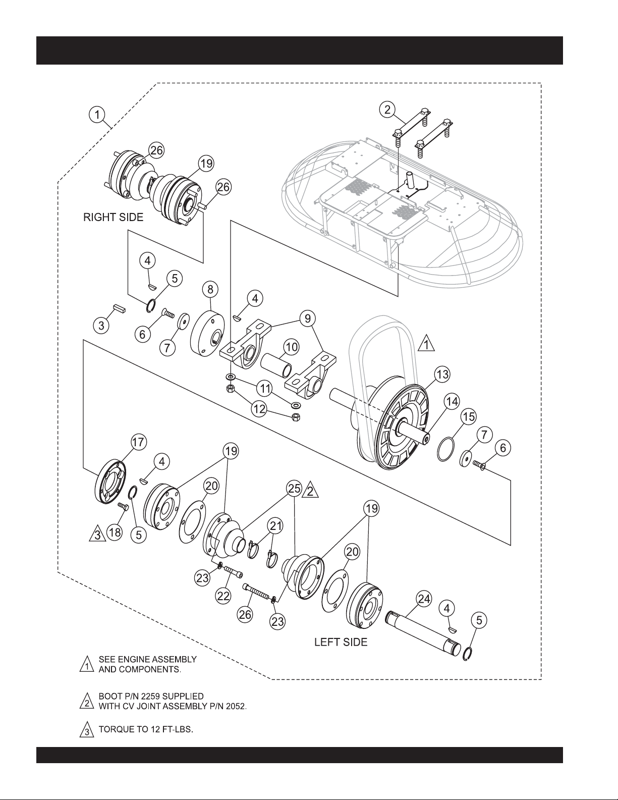
DRIVE ASSY.
JWN-SERIES — DRIVE ASSY.
PAGE 60 — HTN 31V
JWN-SERIES • RIDE-ON POWER TROWEL — PARTS AND OPERATION MANUAL — REV. #8 (12/18/07) — PAGE 60
Page 61

JWN-SERIES — DRIVE ASSY.
DRIVE ASSY.
NO. PART NO. PART NAME QTY. REMARKS
1 20077 DRIVE ASSEMBLY ................................................. 1 ..........INCLUDES ITEMS W/%
2% 20186 PLATE, BEARING MOUNT 2
3% 10909 KEY, 3/16 X 11/16 1
4% 0126 KEY, WOODRUFF #9 4
5% 2090 RING, SNAP TRUARC #5100- 106 4
6% 1146 SCREW, FHSC 5/16- 18 X 1 NYLOC 2
7% 2037 WASHER, RETAINING 2
8% 2029 COUPLER, 1 ID. RIDER 1
9% 10337 BEARING, PILLOW BLOCK FAF YAK- 1 2
10% 20076 SPACER, BEARING SHAFT 1
11% 10136 WASHER, FLAT 3/8 SAE 4
12% 10133 NUT, NYLOC 3/8- 16 4
13% 20137 PULLEY, CVT LOWER COMET 302535C 1
14% 20069 SHAFT, DRIVE BEARING 1
15% 20116 O-RING, SIZE- 031 BUNA N 1
17% 12590 COUPLER, CV JOINT COMET CLUTCH 1
18% 20056 SCREW, HHC 1/4- 28 X 3/4 GRD. 8 3
19% 2052 JOINT, CV W/BOOT ................................................ 4 .......... INCLUDES ITEMS W/
20% 11108 GASKET, CV JOINT BOOT 4
21% 1662 TIE WRAP, CABLE BLACK 4
22% 0243 SCREW, SHC 5/16- 18 X 1-3/4 3
23% 0161C WASHER, LOCK, 5/16 MEDIUM 12
24% 2071 SHAFT, CV JOINT, 7.44LG 2
25%*2259 BOOT, CV JOINT 4
26% 2186 SCREW, SHC 5/16-18 X 2-1/4 PLTD 4
*
JWN- SERIES • RIDE-ON POWER TROWEL — PARTS AND OPERATION MANUAL — REV. #8 (12/18/07) — PAGE 61
Page 62

MUFFLER/BELT ASSY.
JWN-SERIES — MUFFLER/BELT ASSY.
PAGE 62 — HTN 31V
JWN-SERIES • RIDE-ON POWER TROWEL — PARTS AND OPERATION MANUAL — REV. #8 (12/18/07) — PAGE 62
Page 63

JWN-SERIES — MUFFLER/BELT ASSY.
MUFFLER/BELT ASSY.
NO. PART NO. PART NAME QTY. REMARKS
1 20216 ENGINE, HONDA 24 HP GX670 1
2 20336 MUFFLER, 24 HONDA 1
3 0160C WASHER, LOCK 5/16 MEDIUM 4
4 2299 SCREW, HHC M8-1.25 X 16MM 4
5 0300A SCREW, HHC 5/16-18 X 2 4
6 19470 WASHER, FLAT 5/16 USS 8
7 2655 HOUR METER 1
8 8239 RIVET, POP 1/8 DIA X .400 ALUMINUM 2
9 5283 NUT, NYLOC 5/16-18 4
10 20138 BELT, CVT COMET 302609 DF 1
11 12877 CLUTCH, CVT - 1 1/9 COMET 302533C 1
12 20265 SPACER, 1.250 DIA X .188 W X 2.3 LONG 1
13 2955 WASHER, LOCK, 7/16 ZINC 1
14 20264 SCREW, HHC 7/16-20 UNF X 3 1/2 1
15 15410ZJ4999AH FILTER, OIL 1
16 300518C KEY 1
17 0131A SCREW, HHC 1/4-20 X 3/4 4
18 0181B WASHER, LOCK, 1/4 MED 4
19 0948 WASHER, FLAT 1/4 SAE 4
20 2429 HOLDER, SPARE BELT 1
JWN- SERIES • RIDE-ON POWER TROWEL — PARTS AND OPERATION MANUAL — REV. #8 (12/18/07) — PAGE 63
Page 64
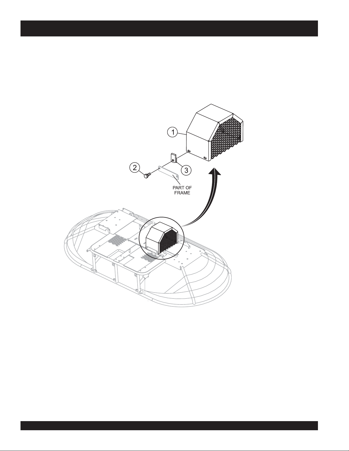
BELT GUARD ASSY.
JWN-SERIES — BELTGUARD ASSY.
PAGE 64 — HTN 31V
JWN-SERIES • RIDE-ON POWER TROWEL — PARTS AND OPERATION MANUAL — REV. #8 (12/18/07) — PAGE 64
Page 65

JWN-SERIES — BELTGUARD ASSY.
BELT GUARD ASSY.
NO. PART NO. PART NAME QTY. REMARKS
1 20100 BELT GUARD 1
2 11819 SCREW, HHC W/WASHER 1/4-20 X 3/4 4
3 11534 NUT, U-TYPE 1/4-20 4
JWN- SERIES • RIDE-ON POWER TROWEL — PARTS AND OPERATION MANUAL — REV. #8 (12/18/07) — PAGE 65
Page 66

SPIDER ASSY. (RIGHT)
JWN-SERIES — SPIDER ASSY. (RIGHT)
PAGE 66 — HTN 31V
JWN-SERIES • RIDE-ON POWER TROWEL — PARTS AND OPERATION MANUAL — REV. #8 (12/18/07) — PAGE 66
Page 67

JWN-SERIES — SPIDER ASSY. (RIGHT)
SPIDER ASSY. (RIGHT)
NO. PART NO. PART NAME QTY. REMARKS
1% 1154A PLATE, WEAR THRUST COLLAR 1
2%+ 10793 THRUST COLLAR W/ BUSHING ............................ 1 .......... INCLUDES ITEMS W/+
3% 12208 WEAR RING 1
4% 12778 BEARING, THRUST 6013 2RSW/ FLANGE 1
5 1141 KEY, 5/16 SQ. X 2-5/8 1
6
7
9
10
11
12
13
14
15
16
17
18
19
20
21
22
23*# 11602 SCREW, HHC 3/8-16 X 1/4.....................................4 .......... REPLACES P/N 2218
24*# 12478 SPIDER, KIT ..........................................................1 .......... INCLUDES ITEMS W/# PLUS
25 20370 PLATE, SPIDER ASSEMBLY RIGHT SIDE ...........1 .......... INCLUDES ITEMS W/
26 BLADE ASSEMBLY .............................................. 4 .......... CONTACT UNIT SALES DEPT./
27+% 1471 THRUST COLLAR BUSHING 1
28% 10968 THRUST COLLAR KIT............................................ 1 .......... INCLUDES ITEMS W/%
12097 SCREW, SQHS 3/8- 16 X 1-3/4 CONE 8 1
*
1456 NUT, HEX FINISH 3/8- 16 1
*
1157A BUSHING,TROWEL ARM 4
*
1317 SPRING, LH TROWEL ARM LEVER 4
*
1555 LEVER, TROWEL ARM LEFT HAND 4
*
4164 PIN, ROLL 5/16 X 1-3/4 4
*
20408 ARM, TROWEL JWN RIGHT 4
*
0202 SCREW, HHC 5/16-18 X 1 8
*
0105 SCREW, HHC 5/16-18 X 1-1/2 16
*
0161C WASHER, LOCK, 5/16 MED 24
*
1162A CAP, GREASE ZERK #2 4
*
1322 SCREW ASSY. , ARM RETAINING 4
*
1875 WASHER, INT. SHKP. 3/8 4
*
0164B SCREW, TROWEL ADJUSTMENT 4
*
1876 NUT, HEX JAM 3/8- 16 CLASS 2B 4
*
0166A WASHER, LOCK, 3/8 MEDIUM 4
*
............................................................................................ INSTRUCTIONS
............................................................................................ ACCESSORY ITEM
*
JWN- SERIES • RIDE-ON POWER TROWEL — PARTS AND OPERATION MANUAL — REV. #8 (12/18/07) — PAGE 67
Page 68

SPIDER ASSY. (LEFT)
JWN-SERIES — SPIDER ASSY. (LEFT)
PAGE 68 — HTN 31V
JWN-SERIES • RIDE-ON POWER TROWEL — PARTS AND OPERATION MANUAL — REV. #8 (12/18/07) — PAGE 68
Page 69

JWN-SERIES — SPIDER ASSY. (LEFT)
SPIDER ASSY. (LEFT)
NO. PART NO. PART NAME QTY. REMARKS
1% 1154A PLATE, WEAR THRUST COLLAR 1
2%+ 10793 THRUST COLLAR W/ BUSHING ............................ 1 .......... INCLUDES ITEMS W/+
3% 12208 WEAR RING 1
4% 12778 BEARING, THRUST 6013 2RSW/ FLANGE 1
5 1141 KEY, 5/16 SQ. X 2-5/8 1
6
7
9
10
11
12
13
14
15
16
17
18
19
20
21
22
23*# 11602 SCREW, HHC 3/8-16 X 1/4.....................................4 .......... REPLACES P/N 2218
24*# 12478 SPIDER, KIT ..........................................................1 .......... INCLUDES ITEMS W/# PLUS
25 20369 PLATE, SPIDER ASSEMBLY LEFT SIDE .............1 .......... INCLUDES ITEMS W/
26 BLADE ASSEMBLY .............................................. 4 .......... CONTACT UNIT SALES DEPT./
27+% 1471 THRUST COLLAR BUSHING 1
28% 10968 THRUST COLLAR KIT............................................ 1 .......... INCLUDES ITEMS W/%
12097 SCREW, SQHS 3/8- 16 X 1-3/4 CONE 8 1
*
1456 NUT, HEX FINISH 3/8- 16 1
*
1157A BUSHING,TROWEL ARM 4
*
1316 SPRING, RH TROWEL ARM LEVER 4
*
1163 LEVER, TROWEL ARM RIGHT HAND 4
*
4164 PIN, ROLL 5/16 X 1-3/4 4
*
20409 ARM, TROWEL JWN LEFT 4
*
0202 SCREW, HHC 5/16-18 X 1 8
*
0105 SCREW, HHC 5/16-18 X 1-1/2 16
*
0161C WASHER, LOCK, 5/16 MED 24
*
1162A CAP, GREASE ZERK #2 4
*
1322 SCREW ASSY. , ARM RETAINING 4
*
1875 WASHER, INT. SHKP. 3/8 4
*
0164B SCREW, TROWEL ADJUSTMENT 4
*
1876 NUT, HEX JAM 3/8- 16 CLASS 2B 4
*
0166A WASHER, LOCK, 3/8 MEDIUM 4
*
............................................................................................ INSTRUCTIONS
............................................................................................ ACCESSORY ITEM
*
JWN- SERIES • RIDE-ON POWER TROWEL — PARTS AND OPERATION MANUAL — REV. #8 (12/18/07) — PAGE 69
Page 70

YOKE ASSY.
JWN-SERIES — YOKE ASSY.
PAGE 70 — HTN 31V
JWN-SERIES • RIDE-ON POWER TROWEL — PARTS AND OPERATION MANUAL — REV. #8 (12/18/07) — PAGE 70
Page 71

JWN-SERIES — YOKE ASSY.
YOKE ASSY.
NO. PART NO. PART NAME QTY. REMARKS
1 9027 YOKE 2
2 0683 PIN, COTTER 3/32 X 3/4 4
3 10136 WASHER, FLAT 3/8 SAE 4
4 9028 PIN, YOKE 2
5 1116 NUT, BRASS JAM 5/16-18 4
6 2008 CABLE ASSEMBLY 25.63 2
JWN- SERIES • RIDE-ON POWER TROWEL — PARTS AND OPERATION MANUAL — REV. #8 (12/18/07) — PAGE 71
Page 72

FOOT PEDALS/THROTTLE ASSY.
JWN-SERIES — FOOT PEDALS/THROTTLE ASSY.
PAGE 72 — HTN 31V
JWN-SERIES • RIDE-ON POWER TROWEL — PARTS AND OPERATION MANUAL — REV. #8 (12/18/07) — PAGE 72
Page 73

JWN-SERIES — FOOT PEDALS/THROTTLE ASSY.
FOOT PEDALS/THROTTLE ASSY.
NO. PART NO. PART NAME QTY. REMARKS
1 20348 CABLE, CONTROL 10-32 X 33 LONG 1
2 2754 ADAPTER, THROTTLE SPRING, LONG 1
3 2753 SPRING, THROTTLE RETURN 1
4 2755 ADAPTER, THROTTLE SPRING, SHORT 1
5 0937 NUT, HEX 10-32 ZINC PLTD 2
6 10019 NUT, NYLOC 10- 32 1
7 2203 WASHER, FLAT #10 SAE 2
8 2153 ROD END, 10- 32 FEMALE RIGHT HAND 1
9 10018 SCREW, SHC 10- 32 X 1 1
10 6014B PIN, COTTER 3/32 X 1 2
11 12657-1 RISER, LEFT FOOT 1
12 12656-1 RISER, RIGHT FOOT 1
13 10136 WASHER, FLAT 3/8 SAE 2
14 3083 SPACER, 3/4 X 3/8 X 7/8 LONG 1
15 2772 PIN, ACCELERATOR PEDAL 1
16 3233 WASHER, FENDER 1.50D X 3/8 ID 4
17 0300B WASHER, FLAT 5/16 SAE 4
18 5283 NUT, NYLOC 5/16-18 4
19 2086 PEDAL ACCELERATOR 1
20 2203 WASHER, FLAT #10 SAE 2
21 20335 LEVER, ENGINE CONTROL 1
22 2153 ROD END, 10-32 FEMALE RH 1
23 10450 SCREW, SHS 10-32 X 1/4 1
24 0937 NUT, HEX 10-32 1
25 19473 CLAMP, HOSE WORM #2 1/4 TO 5/8 1
26 3513 SCREW, HHC 10-32 X 1 1
JWN- SERIES • RIDE-ON POWER TROWEL — PARTS AND OPERATION MANUAL — REV. #8 (12/18/07) — PAGE 73
Page 74
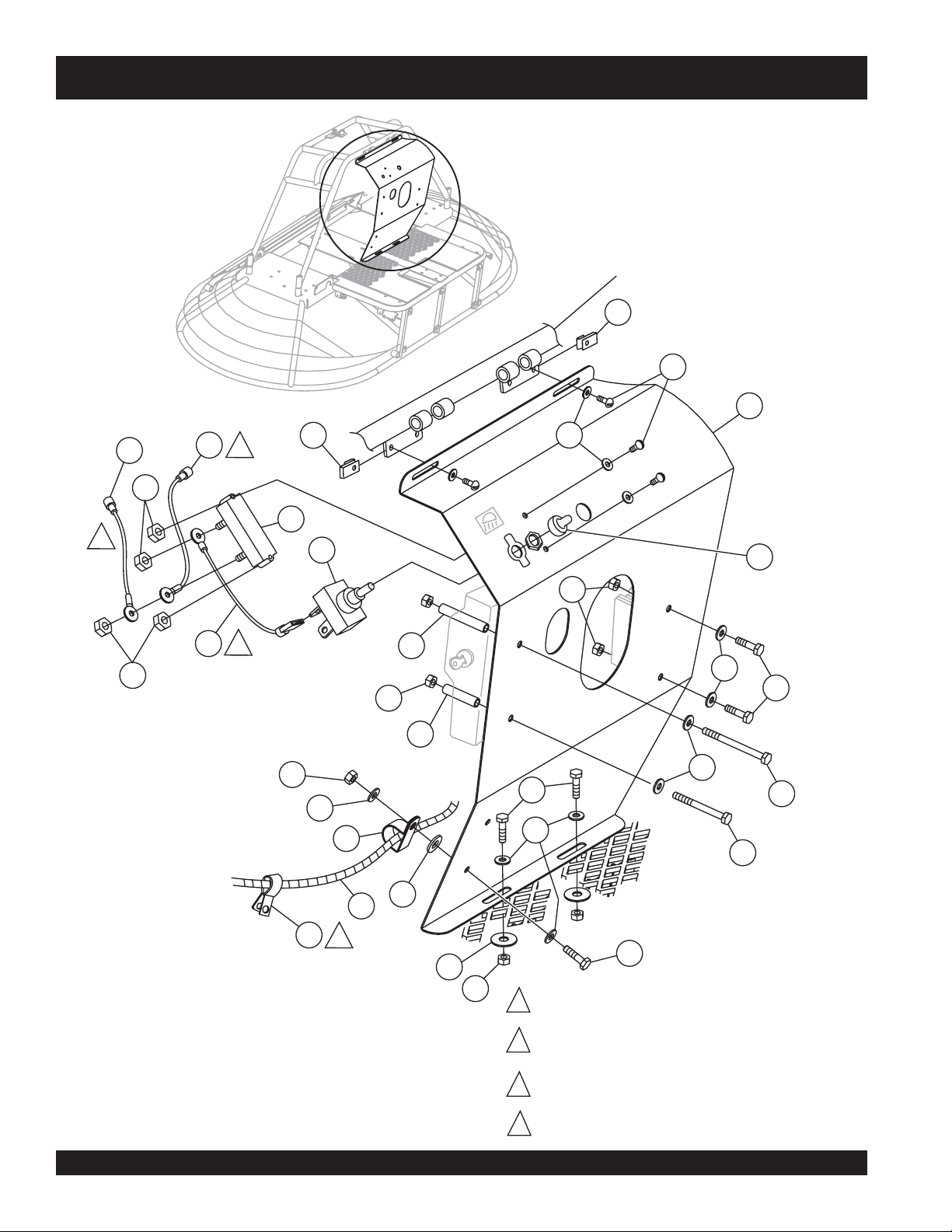
CONTROL PANEL ASSY.
JWN-SERIES — CONTROL PANEL ASSY.
PART OF SEAT/FRAME
ASSEMBLY
7
9
20
6
5
2
7
8
4
1
1
A
B
2
18
11
D
3
3
4
C
16
12
11
10
15
11
10
12
13
12
19
12
14
14
21
17
4
10
15
11
PAGE 74 — HTN 31V
JWN-SERIES • RIDE-ON POWER TROWEL — PARTS AND OPERATION MANUAL — REV. #8 (12/18/07) — PAGE 74
BLK/YEL WIREFROMBREAKER
1
TERMINAL “B” TO HONDABLK/YEL WIRE.
BLK/YEL WIREFRO
2
TERMINAL “A” TO HONDABLK/YEL WIRE.
WHITEWIREFROM LIGHT SWITCH
3
TERMINAL “D” TO BREAKER
TERMINAL “B”.
INSTALL CLAMPTOSCREW ONENGINE.
4
MBREAKER
Page 75

JWN-SERIES — CONTROL PANEL ASSY.
CONTROL PANEL ASSY.
NO. PART NO. PART NAME QTY. REMARKS
1 2673 CIRCUIT BREAKER, 30A, 12V 1
2 4682 SWITCH,TOGGLE ELECTRIC #9061 1
3 20344 WIRE ASSEMBLY, 16 GA. X 5” 1
4 10019 NUT, NYLOC 10- 32 4
5 20342 WIRE ASSEMBLY, 16 GA. X 7” 1
6 20343 WIRE ASSEMBLY, 16 GA. X 10” 1
7 10284 LOCK PLATE, CLIP-ON 10-32 2
8 2203 WASHER, FLAT #10 SAE 4
9 5065B SCREW, RHM 10- 32 X 1/2 4
10 0730 SCREW, HHC 1/4- 20 X 1 5
11 10024 NUT, NYLOC 1/4- 20 7
12 0948 WASHER, FLAT, 1/4 SAE 8
13 19380 SCREW, HHC 1/4- 20 X 3 PLTD 1
14 4538 SCREW, HHC 1/4- 20 X 2-1/2 1
15 20341 SPACER, .38 OD X .05 X 1.56 1
16 20340 SPACER, .38 OD X .05 W X 2.19 1
17 8125 CLAMP, HOSE SUPPORT, 5/8 1
18 8381 BOOT, TOGGLE SWITCH 1
19 11505 CLAMP, HOSE SUPPORT 1/2 INCH LONG 1
20 20339 CONTROL PANEL 1
21 20419 HARNESS, WIRE HONDA RIDER 1
JWN- SERIES • RIDE-ON POWER TROWEL — PARTS AND OPERATION MANUAL — REV. #8 (12/18/07) — PAGE 75
Page 76

FRAME/FUEL ASSY.
JWN-SERIES — FRAME/FUEL ASSY.
PAGE 76 — HTN 31V
JWN-SERIES • RIDE-ON POWER TROWEL — PARTS AND OPERATION MANUAL — REV. #8 (12/18/07) — PAGE 76
Page 77

JWN-SERIES — FRAME/FUEL ASSY.
FRAME/FUEL ASSY.
NO. PART NO. PART NAME QTY. REMARKS
1 12404 TANK, FUEL FIVE GALLON 1
2 11418 FUEL CAP/GAUGE (10.5) 1
3 19633 BUSHING, RUBBER FUEL 1
4 TBD FITTING, 90 4BARB- 4BARB FUEL 1
5 19473 CLAMP, WORM HOSE, #4 (1/4- 5/8) 3
6 60013 HOSE, RUBBER FUEL 0.25 ID .......................... 2 ................. SOLD IN FT. LENGTHS
7 20907 FUEL PUMP ASSEMBLY 1
8 4514 SCREW, HHC 1/4-20 X 5/8 2
9 0948 WASHER, FLAT, 1/4 SAE 6
10 16910ZE8015 FILTER, FUEL 1
11 10024 NUT, NYLOC 1/4- 20 4
12 20366 BRACKET, OP MANUAL BOX 1
13 29057 DOCUMENT BOX, (CP90007- 07) 1
14 12287 SCREW, THP 1/4- 20 X 3/4 SS 4
15 20943-1 FRONT PANEL ................................................... 1 ................. REPLACES P/N 2818
16 11819 SCREW, HHC, WASHER 1/4- 20 X 3/4 6
17 11534 NUT U-TYPE 1/4- 20 6
18 0181B WASHER, LOCK, 1/4 MED 6
19 4514 SCREW, HHC 1/4- 20 X 5/8 4
20 20014-1 FRAME 1
JWN- SERIES • RIDE-ON POWER TROWEL — PARTS AND OPERATION MANUAL — REV. #8 (12/18/07) — PAGE 77
Page 78

BATTERY ASSY.
JWN-SERIES — BATTERY ASSY.
PAGE 78 — HTN 31V
JWN-SERIES • RIDE-ON POWER TROWEL — PARTS AND OPERATION MANUAL — REV. #8 (12/18/07) — PAGE 78
Page 79

JWN-SERIES — BATTERY ASSY.
BATTERY ASSY.
NO. PART NO. PART NAME QTY. REMARKS
1 2509 WING NUT, PLATED 2
2 10031 WASHER, EXT SHKP 1/4 2
3 20356 BRACKET BATTERY HOLD- DOWN 1
4 20194 BOLT, BATTERY HOLD DOWN 2
5 2449 BOX, BATTERY GR UI 1
6 2762 BOOT, TERMINAL 1
7 0131A SCREW, HHC 1/4- 20 X 3/4 2
8 BATTERY, GR. UI WET W /TAG ............................. 1 ..... USE INTERSTATE BATTERY SP-40
9 0181B WASHER,LOCK, 1/4 MEDIUM 2
10 0949 NUT, HEX FINISH 1/4- 20 2
11 12022 CABLE, NEG 20- 1/2 1
12 12675 CABLE, POS. BATTERY, 36’ ‘ 1
13 2623 SCREW, HHC 5/16- 18 X 1- 1/4 1
14 3233 WASHER, FINDER 1.5 OD X 3/8 ID 2
15 11505 CLAMP, HOSE SUPPORT 1/2 INCH LONG 2
16 5283 NUT, NYLOC 5/16- 18 1
JWN- SERIES • RIDE-ON POWER TROWEL — PARTS AND OPERATION MANUAL — REV. #8 (12/18/07) — PAGE 79
Page 80

SPRAY ASSY.
JWN-SERIES — SPRAY ASSY.
5
25
1
27
4
10
5
7
3
9
8
11
2
1
10
26
9
6
12
22
23
6
13
14
6
15
24
19
17
16
13
13
9
10
14
13
18
RETARDANT ONLY
20
17
STEERING HANDLES,
1
SEE PAGE48.
21
PAGE 80 — HTN 31V
JWN-SERIES • RIDE-ON POWER TROWEL — PARTS AND OPERATION MANUAL — REV. #8 (12/18/07) — PAGE 80
Page 81

JWN-SERIES — SPRAY ASSY.
SPRAY ASSY.
NO. PART NO. PART NAME QTY. REMARKS
1 392292 NOZZLE, SPRAY 1
2 2898 WASHER, BONDED NEOPRENE 1 X 1/2 1
3 11222 MOUNT, SPRAY NOZZLE 1
4 1023 SCREW, HHC 3/8-16 X 1 1/4 2
5 10136 WASHER, FLAT 3/8 SAE 4
6 10024 NUT, NYLOC 1/4-20 4
7 2912 FITTING, 90 4BARB-1/4FP 1
8 8128 CLAMP, HOSE SUPPORT 5/16 1
9 0948 WASHER, FLAT 1/4 SAE 4
10 0131A SCREW, HHC 1/4-20 X 3/4 4
11 2914 HOSE, 1/4 ID.........................................................1.......SOLD IN FOOT LENGTHS
12 10022 FITTING, PLASTIC 6BARB-4BARB 1
13 2918 CLAMP, HOSE .475 - .536 ID 4
14 2913 HOSE, 3/8 ID.........................................................1.......SOLD IN FOOT LENGTHS
15 12548 PUMP, SPRAY ASSY. SHURFLO 100-000-21 1
16 2925 FITTING, PLASTIC 90 6BARB-3/8 MP 1
17 2398 CLAMP, 6 1/2 HOSE SIZE 96 2
18 2926 SCREEN, STRAINER 1
19 2108 CAP, SPRAY TANK 1
20 2916 TANK, WATER NPT BOSSES 1
21 2478 DRAIN COCK 1
22 2399 U-BOLT, 1 ID PLTD W/NUTS 2
23 2887 MOUNT, TANK LEFT 1
24 2886 MOUNT, TANK RIGHT 1
25 10133 NUT, NYLOC 3/8-16 4
26 8125 CLAMP, HOSE SUPPORT 5/8 1
27 11430 SWITCH ASSY. , SPRAY 1
JWN- SERIES • RIDE-ON POWER TROWEL — PARTS AND OPERATION MANUAL — REV. #8 (12/18/07) — PAGE 81
Page 82

LIGHT ASSY.
JWN-SERIES — LIGHT ASSY.
1
2
3
4
5
PAGE 82 — HTN 31V
JWN-SERIES • RIDE-ON POWER TROWEL — PARTS AND OPERATION MANUAL — REV. #8 (12/18/07) — PAGE 82
Page 83

JWN-SERIES—LIGHT ASSY.
LIGHT ASSY.
NO. PART NO. PART NAME QTY. REMARKS
1 2896 LIGHT KIT ASSEMBLY 3
2 5283 NUT, NYLOC 5/16-18 4
3 0300B WASHER, FLAT 5/16 SAE 4
4 2531 BRACKET, LIGHT SIDE 2
5 2534 CLAMP ASSEMBLY, MUFFLER 1-3/4 2
JWN- SERIES • RIDE-ON POWER TROWEL — PARTS AND OPERATION MANUAL — REV. #8 (12/18/07) — PAGE 83
Page 84

SEAT FRAME ASSY.
JWN-SERIES — SEAT FRAME ASSY.
PAGE 84 — HTN 31V
JWN-SERIES • RIDE-ON POWER TROWEL — PARTS AND OPERATION MANUAL — REV. #8 (12/18/07) — PAGE 84
Page 85

JWN-SERIES — SEAT FRAME ASSY.
SEAT FRAME ASSY.
NO. PART NO. PART NAME QTY. REMARKS
1 2351 SEAT 1
2 2421 SEAT PLATE 1
3 0161C WASHER, LOCK, 5/16 MEDIUM 4
4 1237 SCREW, SHC, 5/16- 18 X 7/8 NYLOC 4
5 2889 FRAME, SEAT 1
6 11644 SCREW, HHC, WASHER 10- 32 X 5/8 1
7 10237 WASHER, EXT. SHKP, #10 1
8 8156 SCREW, HHC 3/8- 16 X 2-1/2 1
9 4001 WASHER, FLAT 3/8 PLTD STD. USS 1
10 11593 SPRING, THROTTLE RETURN 1
11 10133 NUT, NYLOC 3/8- 16 1
12 0183 PIN, COTTER 1/8 1-1/4 2
13 8081 PIN, CLEVIS 1/2 X 2.75 EFF. 2
14 10306 SCREW, HHC 1/2- 13 X 4-1/2 4
15 20346 SPACER, .56 ID. X 1.00 OD X 1.5L 4
16 10176 NUT, NYLOC1/2- 13 4
17 10019 NUT, NYLOC 10- 32 1
18 12018 CONNECTOR, RELAY 1
19 12017 RELAY, KILL 1
20 12005 SWITCH, KILL COLE- HER #90036- 02 1
JWN- SERIES • RIDE-ON POWER TROWEL — PARTS AND OPERATION MANUAL — REV. #8 (12/18/07) — PAGE 85
Page 86

EZ-MOVER ASSY.
JWN-SERIES — EZ-MOVER ASSY.
PAGE 86 — HTN 31V
JWN-SERIES • RIDE-ON POWER TROWEL — PARTS AND OPERATION MANUAL — REV. #8 (12/18/07) — PAGE 86
Page 87

JWN-SERIES — EZ-MOVER ASSY.
EZ-MOVER ASSY.
NO. PART NO. PART NAME QTY. REMARKS
1 0189 HAND GRIP 2
2 2336 HANDLE, UPPER 1
3 1869 PIN, SNAP 1
4 7170 CLIP 2
5 11684 AXLE, DOLLY 2
6 10440 WHEEL & TIRE 2
7 8151 WASHER, FLAT 3/4 SAE 2
8 0183 PIN, COTTER 2
9 10446 WASHER, FLAT 3/4 4
10 0655 SCREW, HHCS 5/16-18 X 3/4 2
11 0161C WASHER, LOCK 5/16 2
12 0300B WASHER, FLAT 5/16 2
13 2364 WHEEL 2
14 4684 WASHER, FLAT 5/8 2
15 10445 FRAME 1
EZ-MOVER ASSEMBLY -- PURCHASE THROUGH MQ UNIT SALES DEPT.
JWN- SERIES • RIDE-ON POWER TROWEL — PARTS AND OPERATION MANUAL — REV. #8 (12/18/07) — PAGE 87
Page 88

AIR CLEANER ASSY.
HONDA GX-670 — AIR CLEANER ASSY.
PAGE 88 — HTN 31V
JWN-SERIES • RIDE-ON POWER TROWEL — PARTS AND OPERATION MANUAL — REV. #8 (12/18/07) — PAGE 88
Page 89

HONDA GX-670 — AIR CLEANER ASSY.
AIR CLEANER ASSY.
NO. PART NO. PART NAME QTY. REMARKS
1 17210ZJ1841 ELEMENT COMP., AIR CLEANER 1
2 17218ZJ1840 FILTER, OUTER 1
3 17219ZJ1840 CLIP, AIR CLEANER 4
4 17220ZN1000 HOUSING COMP., AIR CLEANER 1
5 17229ZN1000 SEAL, AIR CLEANER HOUSING 1
6 17230ZJ1840 COVER ASSEMBLY, AIR CLEANER 1
8 17233ZJ1840 SEAL, AIR CLEANER COVER 1
9 17234ZJ1840 PLATE, AIR CLEANER SETTING 1
10 17238ZJ4830 COLLAR A, AIR CLEANER 2
11 90003ZJ1840 BOLT, SPECIAL 5MM 2
12 957010602800 BOLT, FLANGE 6 X 28 2
JWN- SERIES • RIDE-ON POWER TROWEL — PARTS AND OPERATION MANUAL — REV. #8 (12/18/07) — PAGE 89
Page 90

CAMSHAFT ASSY.
HONDA GX-670 — CAMSHAFT ASSY.
PAGE 90 — HTN 31V
JWN-SERIES • RIDE-ON POWER TROWEL — PARTS AND OPERATION MANUAL — REV. #8 (12/18/07) — PAGE 90
Page 91

HONDA GX-670 — CAMSHAFT ASSY.
CAMSHAFT ASSY.
NO. PART NO. PART NAME QTY. REMARKS
1 12209ZE8003 SEAL, VALVE STEM 2
2 14100ZJ1842 CAMSHAFT ASSEMBLY ............................. 1 .................. INCLUDES ITEMS W/%
3 14410ZJ1840 ROD, PUSH 4
4 14431ZE2010 ARM, VALVE ROCKER 4
5 14451ZE1013 PIVOT, ROCKER ARM 4
6% 14568ZJ1841 SPRING, WEIGHT RETURN 1
7% 14576ZJ1840 PIN, DECOMPRESSION 1
8 14711ZE3000 VALVE IN. 2
9 14721ZE3000 VALVE, EX. 2
10 14730ZJ1840 LIFTER ASSEMBLY, VALVE ........................ 1 .................. INCLUDES ITEMS W/
11 14751ZE2003 SPRING, VALVE 4
12
13
14 14771ZE2000 RETAINER, IN. VALVE SPRING 2
15 14773ZE2000 RETAINER, EX. VALVE SPRING 2
16 14775ZE2010 SEAT, VALVE 2
17 14781ZE2000 ROTATOR, VALVE 2
18 14791ZE2010 PLATE, PUSH ROD GUIDE 2
19 90005895000 BOLT, FLANGE 5 X 16 1
20 90012ZE0010 BOLT, PIVOT 8MM 4
21 90206ZE1000 NUT, PIVOT ADJ. 4
22 90446357000 WASHER, THRUST 17.2MM 1
23
24 9430108120 PIN A, DOWEL 8 X 12 1
25
26% 9430560282 PIN, SPRING 6 X 28 1
27 957010602500 BOLT, FLANGE 6 X 25 1
14760ZJ1840 SHAFT COMP., VALVE LIFTER 1
*
14764ZJ1840 SPRING, VALVE LIFTER 2
*
90602ZE1000 CLIP, GOVERNOR HOLDER 2
*
9410106800 WASHER, PLAIN 6MM 4
*
*
JWN- SERIES • RIDE-ON POWER TROWEL — PARTS AND OPERATION MANUAL — REV. #8 (12/18/07) — PAGE 91
Page 92
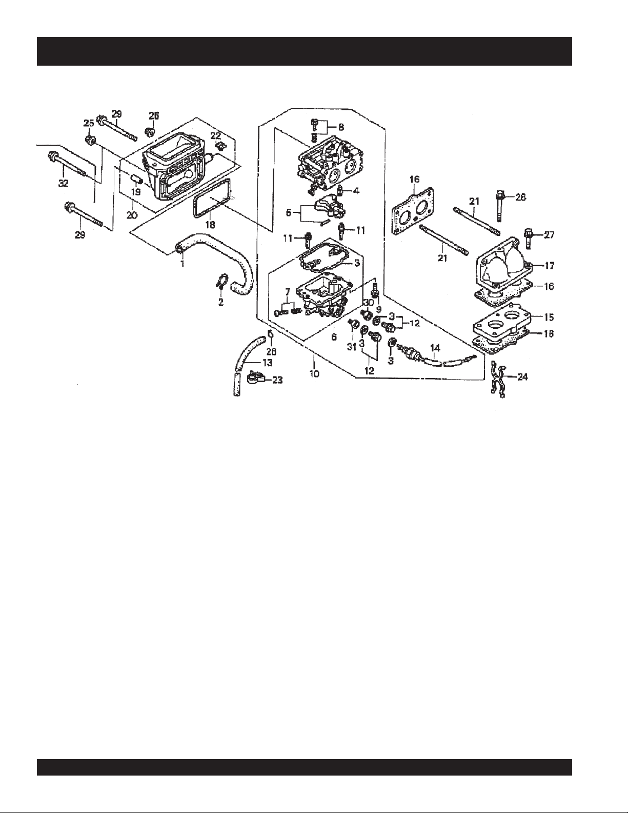
CARBURETOR ASSY.
HONDA GX-670 — CARBURETOR ASSY.
PAGE 92 — HTN 31V
JWN-SERIES • RIDE-ON POWER TROWEL — PARTS AND OPERATION MANUAL — REV. #8 (12/18/07) — PAGE 92
Page 93

HONDA GX-670 — CARBURETOR ASSY.
CARBURETOR ASSY.
NO. PART NO. PART NAME QTY. REMARKS
1 12357ZJ1840 TUBE, BREATHER 1
2 15772551000 CLIP, BREATHER TUBE 1
+ 16010ZN1003 GASKET SET 1
3
*
4
5
6
7
8
9
10 16100ZN1003 CARBURETOR ASSEMBLY (TB01A A) ....... 1 .................. INCLUDES ITEMS W/
11
12
13 16198ZJ1840 TUBE, DRAIN 1
14
15 16211ZN1000 INSULATOR, CARBURETOR 1
16 16221ZN1000 GASKET, CARBURETOR 3
17 17103ZN1010 ELBOW, MANIFOLD 1
18 17228ZN1000 GASKET, AIR CLEANER 1
19% 17238ZJ4830 COLLAR A, AIR CLEANER 4
20 17410ZN1000 ELBOW COMP., AIR CLEANER .................. 1 .................. INCLUDES ITEMS W/%
21 90048ZC3000 BOLT, STUD 6 X 85 2
22% 90314ZJ1840 NUT, INSERT 6MM 2
23 90682959661 CLIP B, CABLE 1
24 91402ZJ1841 CLIP, PURSE LOCK 1
25 9405006000 NUT, FLANGE 6MM 2
26 9500202080 CLIP, TUBE (B8) 1
27 957010603000 BOLT, FLANGE 6 X 30 2
28 957010606500 BOLT, FLANGE 6 X 65 1
29 958010609008 BOLT, FLANGE 6 X 90 2
30
30 99101ZN10960 JET, MAIN #96 (OPTIONAL) 1
31
31 99101ZN10940 JET, MAIN #94 (OPTIONAL) 1
31 99101ZN10980 JET, MAIN #98 (OPTIONAL) 1
31 99101ZN11000 JET, MAIN #100 1
32 958010609008 BOLT, FLANGE 6 X 90 2
16011ZN1003 VALVE, FLOAT 1
*
16013ZN1003 FLOAT SET 1
*
16015ZN1003 CHAMBER SET, FLOAT .............................. 1 .................. INCLUDES ITEMS W/+
*
+ 16024ZN1003 SCREW SET, DRAIN 1
*
16028ZN1003 SCREW SET 1
*
16081ZN1003 SCREW- WASHER 4
*
16150ZN1003 JET, SLOW #54 2
*
16181ZN1003 PLUG SET 2
*
16200ZN1003 VALVE ASSEMBLY, SOLENOID 1
*
99101ZN10920 JET, MAIN #92 (OPTIONAL) 1
*
99101ZN11020 JET, MAIN #102 1
*
*
JWN- SERIES • RIDE-ON POWER TROWEL — PARTS AND OPERATION MANUAL — REV. #8 (12/18/07) — PAGE 93
Page 94

CONTROL (2) ASSY.
HONDA GX-670 — CONTROL ASSY.
PAGE 94 — HTN 31V
JWN-SERIES • RIDE-ON POWER TROWEL — PARTS AND OPERATION MANUAL — REV. #8 (12/18/07) — PAGE 94
Page 95

HONDA GX-670 — CONTROL ASSY.
CONTROL (2) ASSY.
NO. PART NO. PART NAME QTY. REMARKS
1 16263883W10 JOINT, ROD 1
2 16500ZJ1850 CONTROL ASSEMBLY ................................ 1 .................. INCLUDES ITEMS W/
3 16534ZN1000 SPRING, STARTER 1
4 16551ZJ1840 ARM, GOVERNOR 1
5 16555ZN1000 ROD, GOVERNOR 1
6 16561ZN1800 SPRING, GOVERNOR (MANUAL) 1
7 16562ZN1000 SPRING, THROTTLE RETURN 1
8
9
10
11
12 16584883300 SPRING, CONTROL ADJUSTING 2
13 16611ZN1000 ROD, CHOKE CONTROL 1
14 16628ZJ1850 ROD, CHOKE KNOB 1
15 17850ZJ1850 LEVER ASSEMBLY,THROTTLE 1
16 17951921030 KNOB, CHOKE 1
17 17957ZV4000 BUSH, LINKAGE 1
18 90014952000 BOLT, FLANGE 6 X 14 2
19 90015ZE3790 BOLT, GOVERNOR ARM 1
20
21 92301050250A BOLT, SLOT 5 X 25 1
22 93500050250A SCREW, PAN 5 X 25 1
23 9405006000 NUT, FLANGE 6MM 1
24 9425110000 PIN, LOCK 10MM 1
16570ZJ1850 ARM COMP., CONTROL 1
*
16574883300 SPRING, LEVER 1
*
16575ZJ1850 WASHER, CONTROL ARM 1
*
16576883300 SPACER, CONTROL LEVER 2
*
90114SA0000 NUT, SELF- LOCK 6MM 1
*
*
JWN- SERIES • RIDE-ON POWER TROWEL — PARTS AND OPERATION MANUAL — REV. #8 (12/18/07) — PAGE 95
Page 96

CONTROL BOX ASSY.
HONDA GX-670 — CONTROL BOX ASSY.
PAGE 96 — HTN 31V
JWN-SERIES • RIDE-ON POWER TROWEL — PARTS AND OPERATION MANUAL — REV. #8 (12/18/07) — PAGE 96
Page 97

HONDA GX-670 — CONTROL BOX ASSY.
CONTROL BOX ASSY.
NO. PART NO. PART NAME QTY. REMARKS
1
2
3 31620ZG5003 RECTIFIER ASSEMBLY REGULATOR 20A 1
4 32103759000 BRACKET, WIRE HARNESS CLIP 1
5 32105ZJ1800 SUB- WIRE HARNESS ASSEMBLY 1
6 32340ZJ1841 BOX ASSEMBLY CONTROL ................................ 1 .............. INCLUDES ITEMS W/
7
8 32349ZJ1840 STAY, CONTROL BOX 1
9
10
11
12 36103ZE1000 HOLDER, STOP SWITCH WIRE 1
13
14
15 32171GJ1003 CLIP, WIRE HARNESS 1
16 90676SA8003 BAND, WIRE HARNESS 150MM (BLUE) 1
17 91408ZJ1810 TUBE, CORD 30MM 1
18 91504750003 CLIP, WIRE HARNESS 1
19 93500040120H SCREW, PAN 4 X 12 1
20
21
22 957010601000 BOLT, FLANGE 6 X 10 1
23 957010601200 BOLT, FLANGE 6 X 12 2
24*% 9820032500 FUSE, BLADE 25A 1
31612ZE2003 CASE, CONTROL 1
*
31614ZE2003 BRACKET, CASE MOUNTING 1
*
32345ZJ1811 PANEL COMP., CONTROL 1
*
32902892003 BAND 1
*
35100ZJ1841 SWITCH ASSEMBLY COMBINATION .................. 1 .............. INCLUDES ITEMS W/%
*
% 35111880003 KEY COMP. 2
*
87529ZE2860 MARK, CONTROL BOX, EXTERNAL- REG. 1
*
90380MA6010 SCREW, SPECIAL 6 X 12 1
*
94001040800S NUT, HEX. 4MM 1
*
9411104800 WASHER, SPRING 4MM 1
*
*
JWN- SERIES • RIDE-ON POWER TROWEL — PARTS AND OPERATION MANUAL — REV. #8 (12/18/07) — PAGE 97
Page 98

CRANKCASE COVER ASSY.
HONDA GX-670 — CRANKCASE COVER ASSY.
PAGE 98 — HTN 31V
JWN-SERIES • RIDE-ON POWER TROWEL — PARTS AND OPERATION MANUAL — REV. #8 (12/18/07) — PAGE 98
Page 99

HONDA GX-670 — CRANKCASE COVER ASSY.
CRANKCASE COVER ASSY.
NO. PART NO. PART NAME QTY. REMARKS
1 11300ZJ1840 COVER ASSEMBLY, CRANKCASE (Q- TYPE) .... 1 ..........INCLUDES ITEMS W/
2 11381ZJ1840 GASKET, CASE COVER 1
4 15124ZJ1000 COVER ASSEMBLY, OIL PUMP 1
5 15124ZJ1003 ROTOR, OIL PUMP (OUTER) 1
6 15232ZJ1000 SPRING RELIEF VALVE 1
7 15348ZJ1840 COVER, OIL FILTER 1
8 15400PT7005 FILTER, OIL (FILTECH INC.) 1
8 15410ZJ4999AH FILTER, OIL 1
9 15411ZN1000 BASE, OIL FILTER 1
10 15427ZJ1000 SCREEN, OIL FILTER 1
11 15655ZJ1860 DIPSTICK, OIL 1
12
13*% 16511ZJ1840 WEIGHT, GOVERNOR 3
14*% 16512ZJ1840 HOLDER, GOVERNOR WEIGHT 1
15*% 16513ZE2000 PIN, GOVERNOR WEIGHT 3
16
17 90015883000 BOLT, FLANGE 6 X 28 3
18 90018PN3000 HOLDER, OIL FILTER 1
19
20
21
22 91320MJ6003 O- RING 11.8 X 2.4 2
23
24 9430108140 PIN A, DOWEL 8 X 14 2
25 957010602000 BOLT, FLANGE 6 X 20 3
26 957010805000 BOLT, FLANGE 8 X 50 9
27 9621112000 BALL, STEEL #12 (3/8) 1
28 966000601600 BOLT, SOCKET 6 X 16 2
16510ZJ1840 GOVERNOR ASSEMBLY ...................................... 1 ..........INCLUDES ITEMS W/%
*
16531ZE2000 SLIDER, GOVERNOR 1
*
90473147000 WASHER 6 X 16 1
*
90602ZE1000 CLIP, GOVERNOR HOLDER 1
*
91201ZJ1841 OIL SEAL 38 X 58 X 9 1
*
9410106800 WASHER, PLAIN 6MM 1
*
*
JWN- SERIES • RIDE-ON POWER TROWEL — PARTS AND OPERATION MANUAL — REV. #8 (12/18/07) — PAGE 99
Page 100

CRANKSHAFT ASSY.
HONDA GX-670 — CRANKSHAFT ASSY.
PAGE 100 — HTN 31V
JWN-SERIES • RIDE-ON POWER TROWEL — PARTS AND OPERATION MANUAL — REV. #8 (12/18/07) — PAGE 100
 Loading...