

Page 1

OPERATION AND PARTS MANUAL
JTN
RIDE-ON TROWEL
RIDE-ON POWER TROWEL
MODEL #
SERIAL #
© COPYRIGHT 2004, MULTIQUIP INC.
Revision #5 (08/03/06)
MULTIQUIP INC
18910 WILMINGTON AVE. 800-427-1244
CARSON, CALIFORNIA 90746 FAX: 800-672-7877
310-537-3700
800-421-1244 800-478-1244
FAX: 310-537-3927 FAX: 310-631-5032
E-mail:mq@multiquip.com • www:multiquip.com
Atlanta • Boise • Dallas • Houston • Newark
Montreal, Canada • Manchester, UK
Rio De Janiero, Brazil • Guadalajara, Mexico
..
. PARTS DEPARTMENT:
..
SERVICE DEPARTMENT/TECHNICAL ASSISTANCE:
P/N 11261
Page 2

Page 3

HERE'S HOW TO GET HELP
PLEASE HAVE THE MODEL AND SERIAL
NUMBER
MULTIQUIP’S MAIN PHONE NUMBERS
800-421-1244 FAX: 310-537-3927
310-537-3700
PARTS DEPARTMENT
800-427-1244 FAX: 800-672-7877
310-537-3700 FAX: 310-637-3284
MAYCO PARTS
800-306-2926 FAX: 800-672-7877
310-537-3700 FAX: 310-637-3284
SERVICE DEPARTMENT
800-478-1244 FAX: 310-537-4259
310-537-3700
MQ POWER SERVICE DEPARTMENT
800-835-2551 FAX: 310-638-8046
ON-HAND
WHEN CALLING
310-537-3700
TECHNICAL ASSISTANCE
800-478-1244 FAX: 310-631-5032
WARRANTY DEPARTMENT
800-421-1244, EXT. 279 FAX: 310-537-1173
310-537-3700, EXT. 279
JTN RIDE-ON TROWEL — OPERATION & PARTS MANUAL — REV. #5 (08/03/06) — PAGE 3
Page 4

JTN RIDE-ON TROWEL— TABLE OF CONTENTS
MQ WHITEMAN JTN RIDE-ON
POWER TROWEL
Here's How to Get Help ............................................ 3
Table of Contents ...................................................... 4
Training Checklist ...................................................... 5
Daily Pre-Operation Checklist ................................... 6
Parts Ordering Procedures ....................................... 7
Safety Message Alert Symbols ................................. 8
Rules For Safe Operation .................................... 9-12
Operation and Safety Decals .................................. 13
Specifications (Trowel) ............................................ 14
Specifications (Engine) ........................................... 15
Engine Components (Honda) ................................. 16
Engine Components (Vanguard) ............................ 17
General Information ................................................ 18
Controls and Indicators (Front) ............................... 20
Controls and Indicators (Rear) ............................... 21
New Machine Set-up Instructions ........................... 22
Initial Start-up ..................................................... 23-25
Maintenance ...................................................... 26-32
Troubleshooting (Trowel) ................................... 33-34
Troubleshooting (Engine) ...................................35-36
Explanation od Code In Remarks Column.............. 37
Suggested Spare Parts ........................................... 38
4-Blade Spider Assembly (Left-Side) ................. 76-77
4-Blade Spider Assembly (Right-Side) .............. 78-79
Blades and Adjustment Fixture Assembly ......... 80-81
Twin Pitch Handle Assembly (RT/LT) .................82-83
Twin Pitch Tower Assembly (RT/LT) ................... 84-85
Twin Pitch Miter Box Assembly .......................... 86-87
Main Frame Assembly ....................................... 88-89
Seat Frame Assembly ........................................90-91
Retardant Spray Tank Assy.
Retardant Spray Tank Assy.
S/N30058 & Below .. 92-93
S/N30059 & Above.. 94-95
Foot Pedal Assembly ......................................... 96-97
Throttle/Foot Pedal ............................................ 98-99
Battery Assembly ........................................... 100-101
Lights Assembly .............................................102-103
Front Panel Assembly (Vanguard) .................104-105
Front Panel Assembly (Honda)) ..................... 106-107
E-Z Mover & Lift Handle Assembly ................108-109
Wiring Diagram, Vanguard .............................110-111
Wiring Diagram, Honda..................................112-113
Terms and Conditions of Sale ............................... 114
COMPONENT DRAWINGS
Nameplate and Decals....................................... 40-41
Vanguard Engine and Clutch Assembly............. 42-43
Honda Engine and Clutch Assembly ................. 44-45
Drive Assembly .................................................. 46-47
Steering Assy. (LS) S/N 43489 & Below............. 48-49
Steering Assy. (RS) S/N 43489 & Above ............ 50-51
Steering Assy. (LS) S/N 43490-46645 ...............52-53
Steering Assy. (RS) S/N 43490-46645 ............... 54-55
Steering Assy. (LS) S/N 46646~......................... 56-57
Steering Assy. (RS) S/N 46645-61579 ............... 58-59
Steering Assist Assy. S/N 61580 & Above..........60-63
Gearbox Pivot Assembly .................................... 64-65
Gearbox Assembly (Right-Side) ........................ 66-69
Gearbox Assembly (Left-Side) ........................... 70-73
Thrust Bearing Kit .............................................. 74-75
PAGE 4 — JTN RIDE-ON TROWEL— OPERATION & PARTS MANUAL — REV. #5 (08/03/067)
NOTE
Specifications and
part numbers are
subject to change
without notice.
Page 5

JTN RIDE ON TROWEL — TRAINING CHECKLIST
TRAINING CHECKLIST
This checklist will lists some of the minimum requirements for machine maintenance and operation. Please feel free to detach it and
make copies. Use this checklist whenever a new operator is to be trained or it can be used as a review for more experienced
operators.
TSILKCEHCGNINIART
.ON NOITPIRCSED ?KO ETAD
1 .yletelpmoclaunaMs’rotarepOdaeR
2
3 .erudecorpgnileufer,metsysleuF
4 .)deppiuqefi(sthgildnayarpsfonoitarepO
5 .)gninnurtonenihcam(slortnocfonoitarepO
6 .noitarepo"hctiwsllik"taes,slortnocytefaS
7 .serudecorppotsycnegremE
8 .enihcamfoputratS
9 .revohagniniatniaM
01 .gnirevuenaM
11 .gnihctiP
21
dnaenignefognikcehc,stnenopmocfonoitacol,tuoyalenihcaM
.slevelliociluardyh
ehtgnigagnesid,™hctiPniwTsrewotneewtebhctipedalbgnihctaM
.egaknil
31 .seuqinhcetgnihsinifetercnoC
41 .enihcamfonwodtuhS
51 .)spooltfil(enihcamfognitfiL
61 .egarotsdnatropsnartenihcaM
Operator _________________________________________ Trainee __________________________________________
COMMENTS:
JTN RIDE-ON TROWEL — OPERATION & PARTS MANUAL — REV. #5 (08/03/06) — PAGE 5
Page 6

JTN RIDE ON TROWEL — DAILY PRE-OPERATION CHECKLIST
DAILY PRE-OPERATION CHECKLIST
1 .levellioenignE
2 .levellioxobraeG
3 .leveltnaloocrotaidaR
4 .sedalbfonoitidnoC
5 .noitarepohctipedalB
6 .noitarepo)taes("hctiwslliK"
7 .noitarepolortnocgnireetS
8 .stlebfonoitidnoC
TSILKCEHCNOITAREPO-ERPYLIAD
COMMENTS:
PAGE 6 — JTN RIDE-ON TROWEL— OPERATION & PARTS MANUAL — REV. #5 (08/03/067)
Page 7
Effective: June 1st, 2005
Ordering parts has never been easier!
PARTS ORDERING PROCEDURES
Choose from three easy options:
Best Deal!
Order via Internet (Dealers Only):
Order parts on-line using Multiquip’s SmartEquip website!
■
View Parts Diagrams
■
Order Parts
■
Print Specification Information
Goto www.multiquip.com and click on
Order Par ts
to log in and save!
Order via Fax (Dealers Only):
All customers are welcome to order parts via Fax.
Domestic (US) Customers dial:
1-800-6-PARTS-7 (800-672-7877)
Order via Phone:
Non-Dealer Customers:
Contact your local Multiquip Dealer for
parts or call 800-427-1244 for help in
locating a dealer near you.
If you have an MQ Account, to obtain a
Username and Password, E-mail us at:
parts@multiquip.com.
To obtain an MQ Account, contact your
District Sales Manager for more information.
internet
Use the
on
Standard orders
complete part numbers.*
Fax
your order in and qualify for a 3% Discount
on
Standard orders
complete part numbers.*
Domestic (US) Dealers Call:
1-800-427-1244
and qualify for a 5% Discount
for all orders which include
for all orders which include
International Customers
their local Multiquip Representatives for
Parts Ordering information.
Note: Discounts Are Subject To Change
Note: Discounts Are Subject To Change
should contact
When ordering parts, please supply:
❒❒
❒
Dealer Account Number
❒❒
❒❒
❒
Dealer Name and Address
❒❒
❒❒
❒
Shipping Address (if different than billing address)
❒❒
❒❒
❒
Return Fax Number
❒❒
❒❒
❒
Applicable Model Number
❒❒
❒❒
❒
Quantity, Part Number and Description of Each Part
❒❒
NOTE
www.multiquip.com
Unless otherwise indicated by customer, all orders are treated as
within 24 hours. We will make every effort to ship
if received prior to 2PM PST.
WE ACCEPT ALL MAJOR CREDIT CARDS!
JTN RIDE-ON TROWEL — OPERATION & PARTS MANUAL — REV. #5 (08/03/06) — PAGE 7
❒❒
❒
Specify Preferred Method of Shipment:
❒❒
✓
Fed Ex/UPS
■
■
■ Next Day
■
Stock Orders
✓ DHL
Priority One
Ground
Second/Third Day
✓
Tr uck
Standard Orders
Air Shipments
must be noted on fax or web order form.
the same day the order is received,
and will ship
Page 8
JTN RIDE ON TROWEL — SAFETY MESSAGE ALERT SYMBOLS
FOR YOUR SAFETY AND THE SAFETY OF OTHERS!
Safety precautions should be followed at
all times when operating this equipment.
Failure to read and understand the Safety
Messages and Operating Instructions
could result in injury to yourself and others.
This Owner's Manual has been
developed to provide complete
instructions for the safe and efficient
operation of the MQ Whiteman
NOTE
SAFETY MESSAGE ALERT SYMBOLS
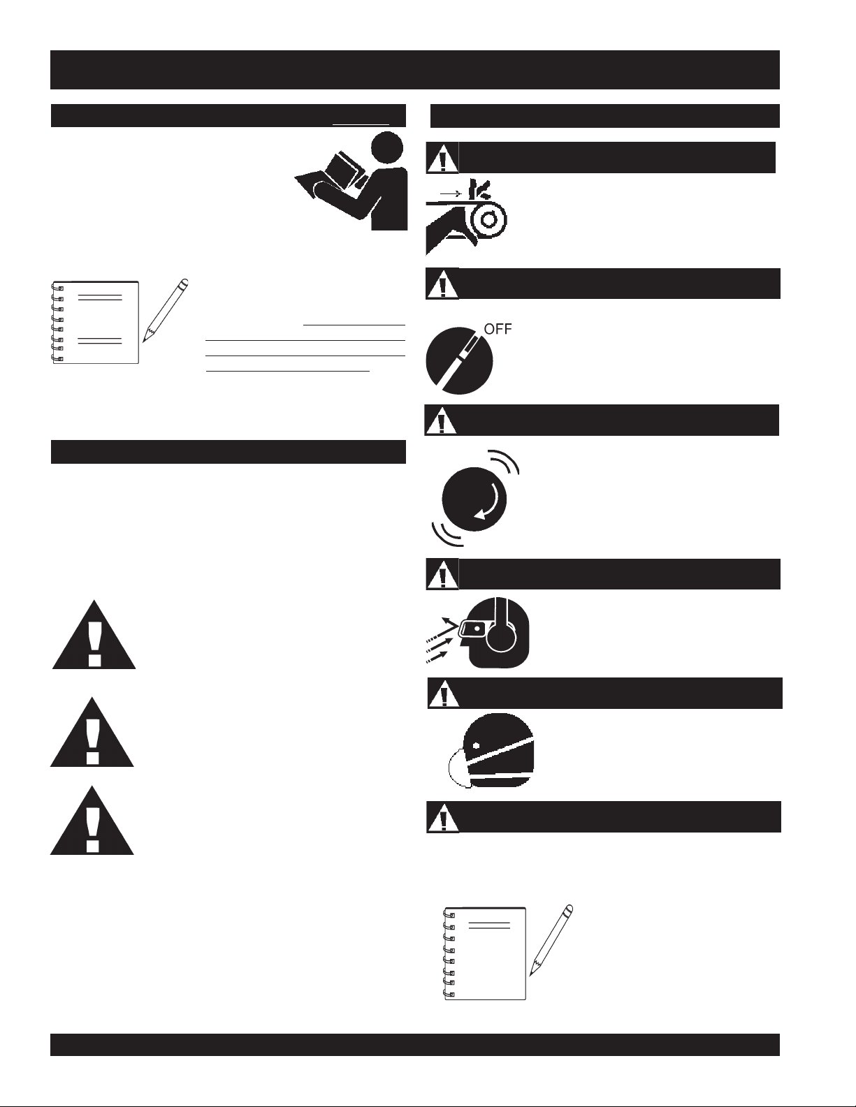
The three (3) Safety Messages shown below will inform you
about potential hazards that could injure you or others. The
Safety Messages specifically address the level of exposure to
the operator, and are preceded by one of three words: DANGER,
WARNING, or CAUTION.
Ride-On Trowel
trowel, ensure that the operating
individual has read and understands
all instructions in this manual.
Before using this
JTN
HAZARD SYMBOLS
Rotating Parts
NEVER operate equipment with covers,
or guards removed. Keep fingers, hands,
hair and clothing away from all moving
parts to prevent injury.
Accidental Starting
ALWAYS place the engine ON/OFF
switch in the OFF position, when the
trowel is not in use.
Over-Speed Conditions
NEVER tamper with the factory settings of
the engine governor settings. Personal
injury and damage to the engine or
equipment can result if operating speed
ranges above maximum allowable.
Sight and Hearing Hazard
DANGER:DANGER:
DANGER:
DANGER:DANGER:
SERIOUSLY injured if you DO NOT follow
directions.
WW
ARNING:ARNING:
W
ARNING:
WW
ARNING:ARNING:
SERIOUSLY injured if you DO NOT follow
directions.
CAUTION: CAUTION:
CAUTION:
CAUTION: CAUTION:
DO NOT follow directions.
Potential hazards associated with the JTN ride-on trowel
operation will be referenced with Hazard Symbols which appear
throughout this manual, and will be referenced in conjunction
with Safety Message Alert Symbols.
You WILL be KILLED or
You CAN be KILLED or
You CAN be injured if you
Other important messages are provided throughout this manual
to help prevent damage to your trowel, other property, or the
surrounding environment.
NOTE
ALWAYS wear approved
hearing
Respiratory Hazard
ALWAYS wear approved
protection when required.
Equipment Damage Messages
protection when required.
This trowel, other property, or the
surrounding environment could be
damaged if you DO NOT follow
instructions.
eye
and
respiratory
PAGE 8 — JTN RIDE-ON TROWEL— OPERATION & PARTS MANUAL — REV. #5 (08/03/067)
Page 9
JTN RIDE ON TROWEL— RULES FOR SAFE OPERATION
■
CAUTION:
Failure to follow instructions in this manual may
lead to serious injury or even death! This
equipment is to be operated by trained and
qualified personnel only! This equipment is
for industrial use only.
The following safety guidelines should always be used when
operating the
SAFETY
■
DO NOT operate or service this equipment
before reading this entire manual.
■
This equipment should not be operated by
persons under 18 years of age.
■
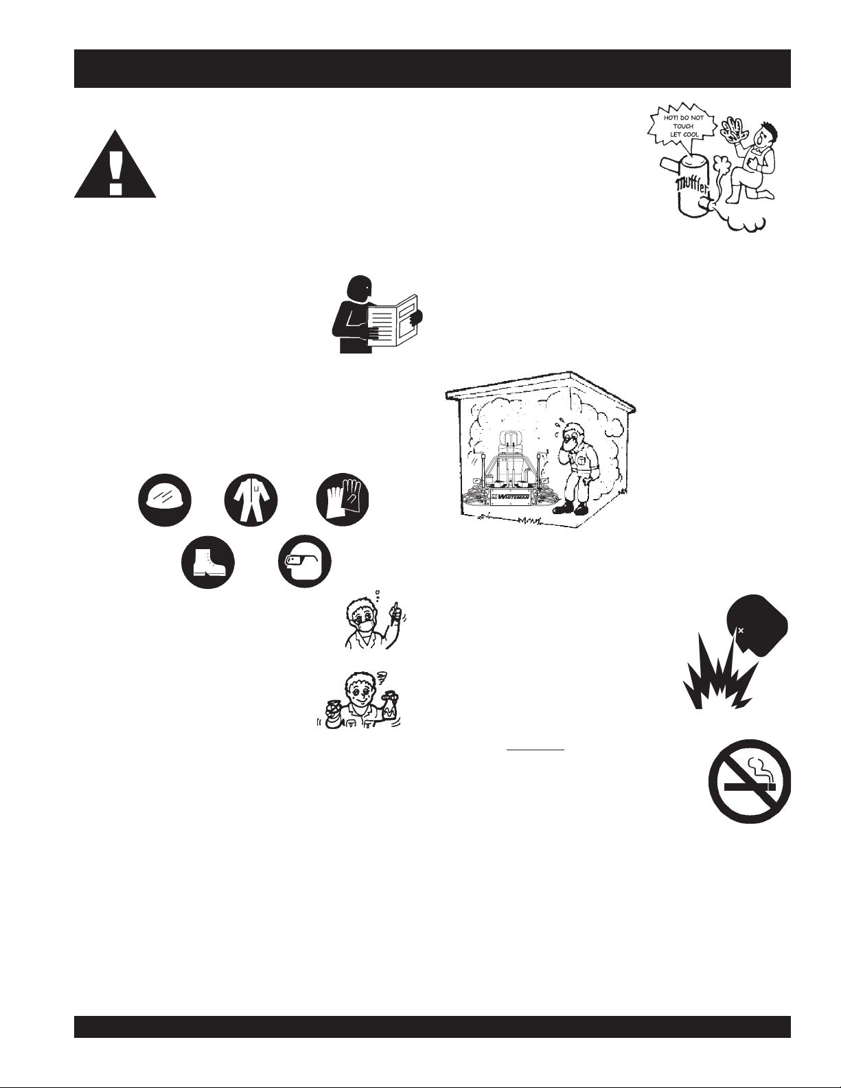
NEVER operate the trowel without proper protective clothing,
shatterproof glasses, steel-toed boots and other protective
devices required by the job.
JTN Ride-On Trowel
.
NEVER touch the hot exhaust
manifold, muffler or cylinder. Allow
these parts to cool before servicing
the trowel.
■
High Temperatures – Allow the engine to cool before adding
fuel or performing service and maintenance functions. Contact
hot!
with
■
The engine of this trowel requires an adequate free flow of
cooling air. NEVER operate the trowel (except electric models)
components can cause serious burns.
in any enclosed or narrow
area where free flow of the
air is restricted. If the air flow
is restricted it will cause
serious damage to the
trowel's engine and may
cause injury to people.
Remember the trowel's
engine gives off
carbon monoxide gas.
DEADLY
■
■
NEVER operate this equipment when not
feeling well due to fatigue, illness or taking
medicine.
■
NEVER operate the trowel under the
influence or drugs or alcohol.
■
NEVER use accessories or attachments, which are not
recommended by Multiquip for this equipment. Damage to
the equipment and/or injury to user may result.
■
Manufacturer does not assume responsibility for any accident
due to equipment modifications.
■
Whenever necessary, replace nameplate, operation and
safety decals when they become difficult read.
■
ALWAYS check the trowel for loosened threads or bolts
before starting.
■
■
■
■
ALWAYS refuel in a well-ventilated area, away from sparks
and open flames.
ALWAYS use extreme caution when
working with flammable liquids. When
refueling, stop the engine and allow it
to cool.
NEVER
machine. Fire or explosion could result from
fuel vapors
engine.
NEVER operate the trowel in an explosive atmosphere or
near combustible materials. An explosion or fire could result
causing severe
Topping-off to filler port is dangerous, as it tends to spill fuel.
smoke
around or near the
, or if fuel is spilled on a
bodily harm or even death.
hot!
JTN RIDE-ON TROWEL — OPERATION & PARTS MANUAL — REV. #5 (08/03/06) — PAGE 9
Page 10

JTN RIDE-ON TROWEL — RULES FOR SAFE OPERATION
The following safety guidelines should always be used when
operating the JTN ride-on trowel:
General Safety
■
DO NOT operate or service this equipment before reading
this entire manual.
■
This equipment should not be operated by persons under 18
years of age.
■
DO NOT operate this trowel unless all guards and safety
devices are attached and in place.
■
ALWAYS check to make sure that the operating area is clear
before starting the engine.
■
ALWAYS test the
■
NEVER place your feet inside the guard rings while starting
or operating this trowel.
■
ALWAYS keep clear of rotating or moving parts while
operating this trowel.
■
NEVER leave the trowel unattended while running.
■
NEVER modify the safety kill switch. It is design for operator
safety.
■
ALWAYS refuel in a well-ventilated area, away from sparks
and open flames.
■
ALWAYS use extreme caution when working with flammable
liquids. When refueling, stop the engine and allow it to cool.
DO NOT
explosion could result from flames or sparks, or if fuel is spilled
on a hot engine.
safety kill switch
smoke
before operating the trowel .
around or near the machine. Fire or
■
NEVER run engine without air filter. Severe engine damage
may occur.
■
ALWAYS service air filter frequently to prevent engine
malfunction.
■
ALWAYS be sure the operator is familiar with proper safety
precautions when operating the trowel.
■
ALWAYS store trowel properly when not in use.
■
DO NOT leave the trowel running unattended.
■
DO NOT allow unauthorized people to operate this trowel.
■
ALWAYS read, understand, and follow procedures in
Operator’s Manual before attempting to operate equipment.
■
Refer to the
Owner's Manual
information.
Transporting
■
ALWAYS shutdown engine before transporting.
■
Tighten fuel tank cap securely.
■
If the trowel is being transported via a trailer, make sure
trailer complies with all local and state safety
transportation laws. See “
for basic towing techniques in this manual.
Briggs and Stratton or Honda Engine
for engine technical questions or
Towing Safety Precautions
”
■
Moving Parts - Shut down the engine and disconnect battery
before performing service or maintenance functions. Contact
with moving parts can cause serious injury.
■
When lifting of the trowel is required, a chain can be attached
to the lift loops, allowing a forklift or crane to lift the ride-on
trowel up onto a slab of concrete. The strap or chain should
have a minimum 2,000 pounds (1000-kg) lifting capacity and
the lifting gear must be capable of lifting at least this amount.
■
NEVER stand underneath the trowel when it is being lifted.
■
This ride-on trowel is very
Use proper heavy lifting procedures and DO NOT attempt to
lift the ride-on trowel by the
PAGE 10 — JTN RIDE-ON TROWEL— OPERATION & PARTS MANUAL — REV. #5 (08/03/067)
heavy
and awkward to move around.
guard rings
.
Page 11
JTN RIDE-ON TROWEL— RULES FOR SAFE OPERATION
Maintenance Safety
■
Disconnect the battery and spark plug wires before attempting
any type of service.
■
Securely support any trowel components that must be raised.
■
NEVER lubricate components or attempt service on a running
machine.
■
ALWAYS allow the trowel a proper amount of time to cool
before servicing.
■
Keep the trowel in proper running condition.
■
Make sure that there is no buildup of concrete, grease, oil or
debris on the trowel.
■
Fix damage to the trowel immediately and always replace
broken parts.
■
Dispose of hazardous waste properly. Examples of potentially
hazardous waste are used motor oil, fuel and fuel filters.
■
DO NOT use plastic food containers to dispose of hazardous
waste.
■
DO NOT pour waste, oil or fuel directly onto the ground,
down a drain or into any water source.
■
NEVER store trowel with fuel in the tank for any extended
period of time. Always clean up spilled fuel immediately.
Battery
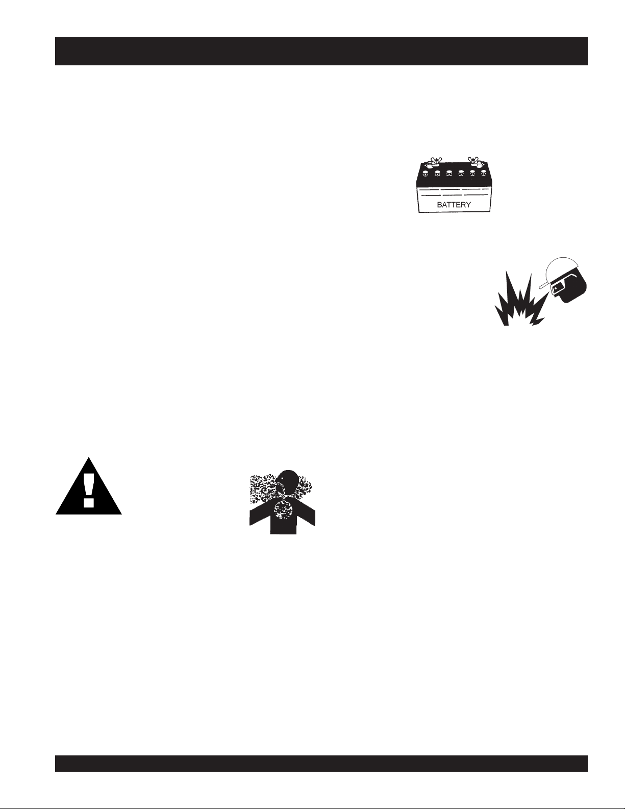
The battery contains acids that can cause injury to the eyes
and skin. To avoid eye irritation,
Use well insulated gloves when picking up the battery. Use
the following guidelines when handling the battery:
■
■
■
■
always
DO NOT drop the battery. There is the possibility of risk
that the battery may explode.
DO NOT expose the battery to
open flames, sparks, cigarettes
etc. The battery contains
combustible gases and liquids. If
these gases and liquids come in
contact with a flame or spark, an
explosion could occur.
ALWAYS keep the battery charged. If the battery is not
charged a buildup of combustible gas will occur.
ALWAYS keep battery charging and cables in good working
condition. Repair or replace all worn cables.
wear safety glasses.
DANGER:DANGER:
DANGER:
DANGER:DANGER:
Pay close attention to
ventilation when operating
the trowel inside tunnels
and caves. The engine
exhaust contains noxious elements.
Engine exhaust must be routed to a
ventilated area.
■
ALWAYS disconnect the
performing service on the trowel.
■
ALWAYS recharge the battery in an vented air
environment, to avoid risk of a dangerous concentration
of combustible gases.
■
In case the battery liquid (dilute sulfuric acid) comes in
contact with
immediately with plenty of water.
■
In case the battery liquid (dilute sulfuric acid) comes in
contact with your eyes, rinse eyes immediately with plenty
of water, then contact the nearest doctor or hospital, and
seek medical attention.
clothing or skin
negative battery terminal
, rinse skin or clothing
before
JTN RIDE-ON TROWEL — OPERATION & PARTS MANUAL — REV. #5 (08/03/06) — PAGE 11
Page 12
JTN RIDE-ON TROWEL — RULES FOR SAFE OPERATION
Towing Safety Precautions
CAUTION:CAUTION:
CAUTION:
CAUTION:CAUTION:
Conform to
(DOT)
towing generator.
To reduce the possibility of an accident while transporting
the trowel on public roads, always make sure the trailer that
supports the trowel and the towing vehicle are in good
operating condition and both units are mechanically sound.
The following list of suggestions should be used when towing
your generator:
■
Make sure the hitch and coupling of the towing vehicle
are rated equal to, or greater than the trailer "gross vehicle
weight rating" (GVWR) of 6,000 lbs.
■
ALWAYS inspect the hitch and coupling for wear. NEVER
tow a trailer with defective hitches, couplings, chains
etc.
Department of Transportation
Safety Towing Regulations
before
■
Avoid sharp turns.
■
Trailer should be adjusted to a level position at all times
when towing.
■
Raise and lock trailer wheel stand in up position when
transporting.
■
DOT Requirements include the following:
z
z
Emergencies
■
ALWAYS know the location of the nearest
■
ALWAYS know the location of the nearest and
Connect and test electric brake operation.
Secure portable power cables in cable tray with
tie wraps.
fire extinguisher
first aid kit
.
.
■
Check the tire air pressure on both towing vehicle and
trailer.
Also check the tire tread wear on both vehicles.
■
ALWAYS make sure the trailer is equipped with a "Safety
Chain".
■
ALWAYS attach trailer’s safety chains to towing vehicle
properly.
■
ALWAYS make sure the vehicle and trailer directional,
backup, brake, and trailer lights are connected and
working properly.
■
The maximum speed for highway towing is 45 MPH
unless posted otherwise. Recommended off-road towing
is not to exceed 10 MPH or less depending on type of
terrain.
■
Place
rolling, while parked.
■
Use the trailer’s swivel jack to adjust the trailer height to
a level position while parked.
■
Avoid sudden stops and starts. This can cause skidding,
or jack-knifing. Smooth, gradual starts and stops will
improve towing.
Trailer tires should be inflated to 50 psi cold.
chock blocks
underneath each wheel to prevent
■
In emergencies
nearest phone or
Also know the phone numbers of the nearest
ambulance, doctor
information will be invaluable in the case of an
emergency.
always
know the location of the
keep a phone on the job site
and
fire department
.
. This
PAGE 12 — JTN RIDE-ON TROWEL— OPERATION & PARTS MANUAL — REV. #5 (08/03/067)
Page 13

JTN RIDE-ON TROWEL— RULES FOR SAFE OPERATION
Machine Safety Decals
The JTN-Series Ride-On Trowel is equipped with a number of safety decals. These decals are provided for operator safety and
maintenance information. Figure 1 below illustrates these decals as they appear on the machine. Should any of these decals
become unreadable, replacements can be obtained from your dealer.
Figure 1. Operation and Safety Decals
JTN RIDE-ON TROWEL — OPERATION & PARTS MANUAL — REV. #5 (08/03/06) — PAGE 13
Page 14
JTN RIDE-ON TROWEL — SPECIFICATIONS (TROWEL)
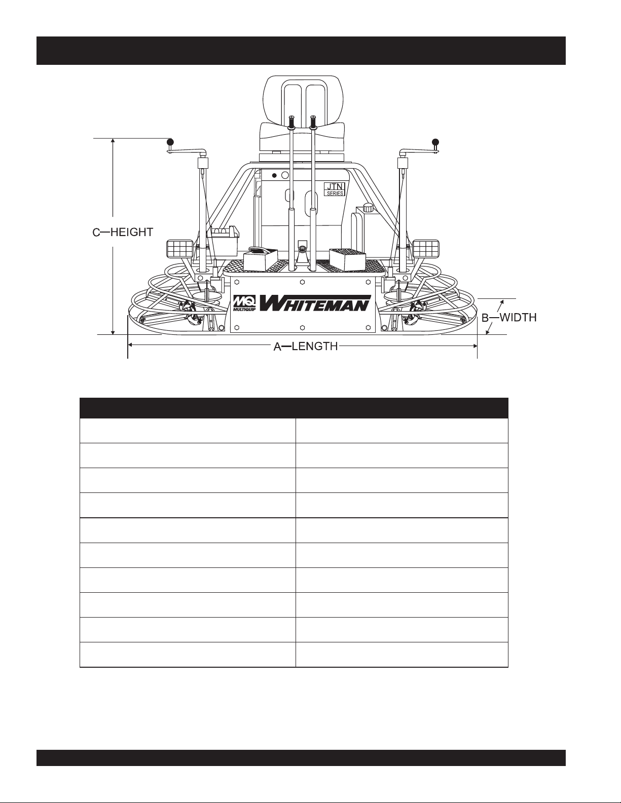
Figure 2. Trowel Dimensions
htgneL–A ).mc691(.ni0.77
htdiW–B ).mc99(.ni0.93
1
thgieH–C
gnitarepO).sgk(.sbl–thgieW ).sgk902(.sbl064
yticapaCknaTleuF )sretil8(.lag2.2
emiTnuR .rh/.lag95.1
deepSrotoR MPR831
rotoR/sedalB 4
htdiWhtaP ).mc191(.ni57
yticapaCliOnoitacirbuLxobraeG )sretil897.(.zo72
)leworT(snoitacificepS.1elbaT
).mc711(.ni0.64
NOTE:
1. This value does not include seat height. To obtain total
height (seat ) add 4 inches (10.2 cm.).
PAGE 14 — JTN RIDE-ON TROWEL— OPERATION & PARTS MANUAL — REV. #5 (08/03/067)
Page 15

JTN RIDE-ON TROWEL — SPECIFICATIONS (ENGINE)
)enignE(snoitacificepS.2elbaT
erutcafunaMenignE)nottartS&sggirB(draugnaVadnoH
epyT/noitacificepSenignE
ekortSXeroB
tnemcalpsiDcc075cc416
rewoPmumixaM)mpr006,3(ph0.81)mpr006,3(ph0.02
TmumixaM
euqro
deepSeldImpr
MPRdaoLoNmumixaMmpr001±0063mpr001±0063
noitpmusnoCleuFcificepS
yticapaCknaTleuF
apaCliOesacknarC
ytic
metsySgnitratScirtcelE/lioceRcirtcelE/lioceR
p
aGgulPkrapS
renaelCriAtnemelElauDtnemelElauD
thgi
eWyrD
HXWXLsnoisnemiD
50.6(
ia,evlavdaehrevo
96x88.17(
±004,1mpr051±004,1
.rh/.slag46.1
snollag02.2
)sretil23.8(
stnip25.3
)sretil66.1(
.sbl0.47
).gk65.33(
,rednilycniwT106800744053
deloocr
.ni57.2x28.2
).mm58.
)mpr008,2(.sbl-tf07.13
)mpr008,2(m-fgk73.41
).rh/sretil/
.ni030.0-820.0
).mm67.0-07.0(
.ni41.81x06.01x04.71
.mm164x962x244
.ni06.2x30.3
).mm0.66x0.77(
.rh/.slag45.1
).rh/sretil/28.5(
snollag02.2
)sretil23.8(
stnip81.3
)sretil05.1(
.ni130.0-820.0
).mm87.0-07.0(
.sbl6.29
).gk0.24(
x03.51
daehrevo,ekorts-41BXQ1K026XG
)niwT-V°09(srednilyc2,evlav
)mpr005,2(.sbl-tf5.23
)mpr005,2(m-fgk05.4
.ni8.71x0.81
.mm254x754x883
JTN RIDE-ON TROWEL — OPERATION & PARTS MANUAL — REV. #5 (08/03/06) — PAGE 15
Page 16

INITIAL SERVICING
JTN RIDE-ON TROWEL— ENGINE COMPONENTS (HONDA)
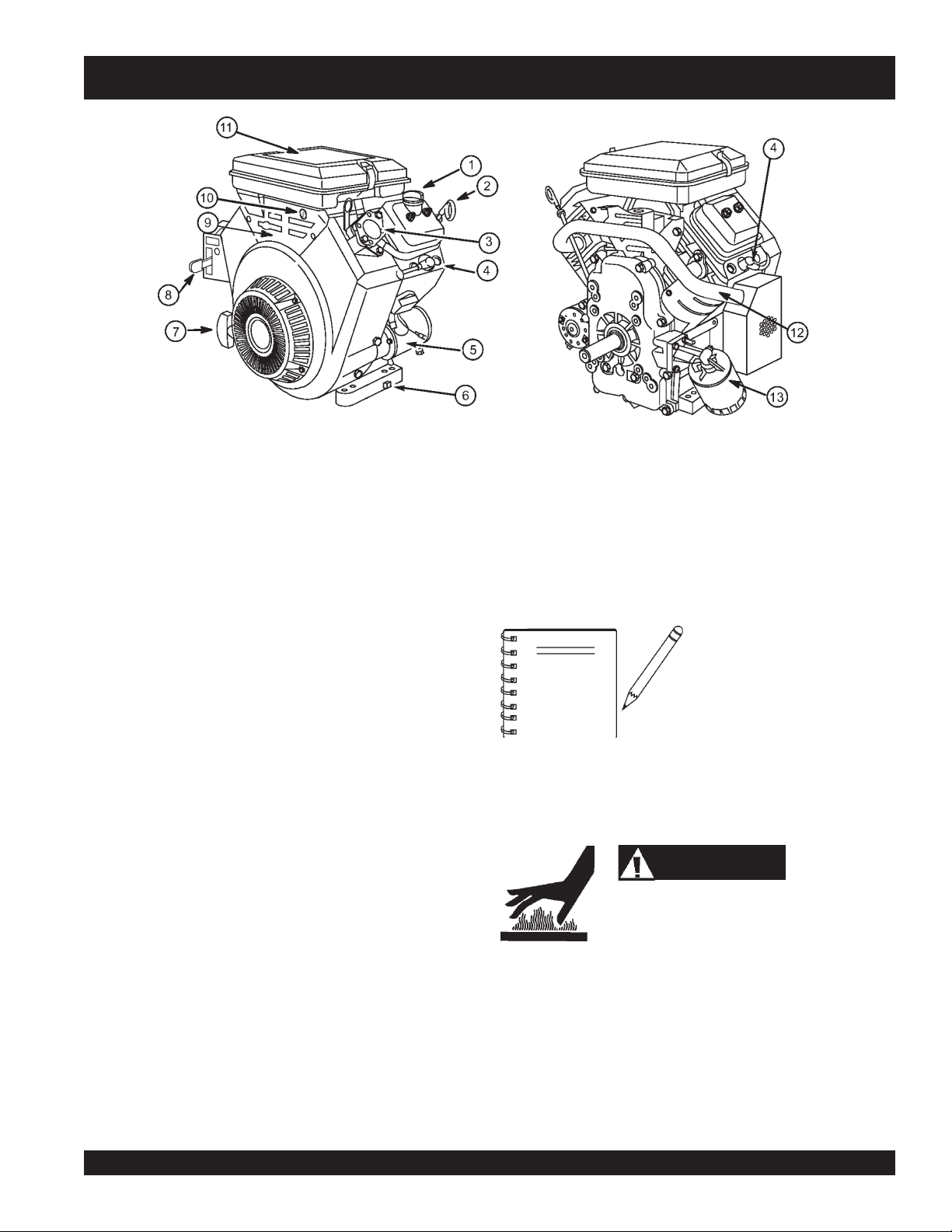
Figure 3. Engine Controls and Components (Honda)
The engine (Figure 3) must be checked for proper lubrication and
filled with fuel prior to operation. Refer to the manufacturer's engine
manual for instructions & details of operation and servicing. The
engine shown above is a HONDA engine. Operation for other
types of engines may vary somewhat.
1. Fuel Filter – Filters fuel for contaminants.
2. Air Filter – Prevents dirt and other debris from entering the
fuel system. Unsnap air filter cover to gain access to filter
element.
3. Choke Knob – Used in the starting of a cold engine or in
cold weather conditions. The choke enriches the fuel
mixture.
4. Engine ON/OFF Switch – "ON" position permits engine
starting, "OFF" position stops engine operations.
5. Recoil Starter (pull rope) – Manual-starting method. Pull
the starter grip until resistance is felt, then pull briskly and
smoothly.
6. Oil Sensor Switch – This switch monitors the oil level in
the engine crankcase. In the event of low oil, the engine
will be shut down.
7. Oil Filter – Spin-on type, filters oil for contaminants.
8. Throttle Lever – Controlled by accelerator pedal,
increases or decreases engine RPM.
10. Spark Plug – Provides spark to the ignition system. Set
spark plug gap to 0.71 - 0.78 mm (0.028 - 0.031 inch) Clean
spark plug once a week.
11. Oil Filler Cap – Remove cap to refill or replace oil with
recommended type as listed in Table 3. Make sure cap is
tightened securely. DO NOT over fill.
12. Muffler –Used to reduce noise and emissions.
touch the muffler while it is hot! Serious burns can result.
NEVER
operating. NEVER operate the engine with the muffler removed.
13. Oil Dip Stick – Remove to check amount and condition of
oil in crankcase.
14. Starter – Starts engine when ignition key is rotated to the
"ON" position.
NEVER
operate the engine with the muffler removed.
WARNING
Engine components can generate extreme heat.
To prevent burns, DO NOT touch these areas
while the engine is running or immediately after
15. Oil Drain Plug – Remove to drain crankcase oil.
PAGE 16 — JTN RIDE-ON TROWEL— OPERATION & PARTS MANUAL — REV. #5 (08/03/067)
Page 17
JTN RIDE-ON TROWEL — ENGINE COMPONENTS (VANGUARD)
Figure 4. Engine Controls and Components (Vanguard)
INITIAL SERVICING
The engine (Figure 4) must be checked for proper lubrication and
filled with fuel prior to operation. Refer to the manufacturers Engine
manual for instructions & details of operation and servicing.
1. Oil Fill Cap – Remove cap to refill or replace oil with
recommended type as listed in Table 3. Make sure cap is
tightened securely. DO NOT over fill.
2. Oil Dipstick – Remove to check amount and condition of
oil in crankcase.
3. Fuel Pump – Pumps fuel from the fuel tank into the
carburetor.
4. Spark Plugs – Provides spark to the ignition system. Set
spark plug gap to 0.71 - 0.76 mm (0.028 - 0.030 inch) Clean
spark plug once a week.
5. Electric Starter – Starts engine when ignition key is rotated
to the “ON” position.
10. Ignition Switch – Insert the ignition key here to start the
engine. Turn the key clockwise to the
continue turning clockwise to the
release. To stop the engine turn the key fully counterclockwise to the
NOTE
11. Air Filter – Prevents dirt and other debris from entering
the fuel system. Release the latches on the sides of the air
filter cover to gain access to filter element.
STOP
ON
position, then
START
position.
Operating the engine without
an air filter, with a damaged air
filter, or a filter in need of
replacement will allow dirt to
enter the engine, causing rapid
engine wear.
position and
6. Oil Drain Plug – Remove to drain crankcase oil.
7. Recoil Starter (pull rope) – Manual-starting method. Pull
the starter grip until resistance is felt, then pull briskly and
smoothly.
8. Throttle Lever – Used to adjust engine RPM speed (lever
SLOW
advanced forward
FAST
).
9. Choke Lever – Used in the starting of a cold engine, or in
cold weather conditions. The choke enriches the fuel
mixture.
JTN RIDE-ON TROWEL — OPERATION & PARTS MANUAL — REV. #5 (08/03/06) — PAGE 17
, lever back toward operator
12. Muffler – Used to reduce noise and emissions.
13. Oil Filter – Prevents dirt and other debris from entering the
WARNING
Engine components can generate extreme heat.
To prevent burns, DO NOT touch these areas
while the engine is running or immediately after
operating. NEVER operate the engine with the
muffler removed.
NEVER
touch the muffler while it is hot! Serious burns can result.
NEVER
engine. Service the oil filter as recommended in the
maintenance section of this manual.
operate the engine with the muffler removed.
Page 18

JTN RIDE-ON TROWEL — GENERAL INFORMATION
JTN RIDE-ON TROWEL FAMILIARIZATION
The JTN ride-on trowel is designed for the floating and finishing
of concrete slabs. This ride-on trowel is a non-overlapping trowel.
Take a walk around the trowel. Take notice of all the major
components (see Figures 5 and 6) like the engine, blades, air
cleaner, fuel system, fuel shut-off valve, ignition switch etc. Check
that there is always oil in the engine, and gear oil in the gear box
assembly.
Read all the safety instructions carefully. Safety instructions will
be found throughout this manual and on the machine. Keep all
safety information in good, readable condition. Operators should
be well trained on the operation and maintenance of the trowel.
Look at the operator control levers. Grab the control levers and
move them around a bit. Look to see how moving the control
levers causes the gearboxes and frame to move.
Notice the foot pedal which controls the engine speed. Also take
a look at the main driveline of the trowel. Take note and reference
how the belts look, this is the way the belts should look when
adjusted properly.
Before using your ride-on trowel, test it on a flat watered down
section of finished concrete. This trial test run will increase your
confidence in using the trowel and at the same time it will
familiarize you with the trowel’s controls and indicators. In addition
you will understand how the trowel will handle under actual
conditions.
Engine
This trowel is equipped with either a air-cooled 18 HP Vanguard
(Briggs and Stratton) gasoline engine or a 20 HP air-cooled
Honda gasoline engine (GX620). Refer to the engine owner’s
manual for specific instructions regarding engine operation. This
manual is included with the ride-on trowel at the time of shipping
from Whiteman. Please contact your nearest Multiquip Dealer
for a replacement should the original manual disappear.
Gearboxes
The JTN ride-on trowel consist of two separate gearbox
assemblies that are enclosed in rugged cast aluminum gear
cases. The main gear is a high quality bronze and steel
composite. The worm gear is composed of hardened steel.
Cooling fins and fans are integrated into the gearbox to provide
maximum cooling for the gearbox oil. The gearbox casing holds
50% more oil capacity than competitors, which allows more
lubrication to be provided to critical points.
Steering Assist
Dual control levers located in front of the operator's seat are
provided for steering the trowel. The control levers are linked to
two spring loaded cylinders. Push the left control lever forward
and pull the right control lever backward and the trowel will rotate
clockwise on approximately a center axis. Pull the left control
lever backward and push the right control lever forward and the
trowel will rotate counterclockwise. See Table 4 for a complete
description on the control levers directional positioning.
Constant Velocity Joints (CV-Joints)
Constant velocity joints insure the efficient transfer of power to
the drive shaft and maintains the timing of the gearboxes without
any chance of slippage.
Training
For proper training, please use the “TRAINING CHECKLIST”
located in the front of this manual. This checklist will provide an
outline for an experienced operator to provide training to a new
operator.
Blades
The blades of the trowel finish the concrete as they are rotated
around the surface. Blades are classified as
(8 inches wide),
inches wide). This trowel comes equipped with four blades
per rotor equally spaced in a radial pattern and attached to
vertical rotating shaft by means of a
float
(10 or 8 inches wide), and finish (6
spider assembly.
PAGE 18 — JTN RIDE-ON TROWEL— OPERATION & PARTS MANUAL — REV. #5 (08/03/067)
combination
Page 19

NOTE PAGE
JTN RIDE-ON TROWEL — OPERATION & PARTS MANUAL — REV. #5 (08/03/06) — PAGE 19
Page 20

JTN RIDE-ON TROWEL — CONTROLS AND INDICATORS
Figure 5. JTN Controls and Indicators (Front)
1. Seat – Place for operator to sit. Engine will not start unless
operator is seated. Seat is adjustable, fore and aft for
operator comfort.
2. Steering Control Lever (right-side) -Allows the unit to
move in either a forward, reverse left or right direction.
3. Retardant Spray Control Button – When pressed allows
retardant spray to flow through the spray nozzle located at
the front of the machine.
4. Twin Pitch Control – Adjusts the blade pitch for right side
of the trowel. Turn the crank as marked on its top surface to
increase or decrease blade pitch.
5. Twin Pitch Control – Adjusts the blade pitch for left side
of the trowel. Turn the crank as marked on its top surface to
increase or decrease blade pitch.
6. Steering Control Lever (left-side) -Allows the unit to
move in either a forward, reverse left or right direction.
7. Light Switch – When activated, turns on four halogen
lights. Lights offer better visibility when working indoors.
8. Ignition Switch – With key inserted turn clockwise to start
engine.
9. Fuel Gauge/Filler Cap - Indicates the amount of fuel in
the fuel tank. Remove this cap to add fuel.
10. Fuel Tank - Holds 2.2 gallons of unleaded gasoline.
11. Spare Belt Carrier - Contains 2 spare belts. Belts are used
on the drive pulley.
12. Left Foot Riser – Operator foot rest pedal.
13. Spray Nozzle – Spray nozzle for retardant.
14. Right Foot Pedal – Controls blade speed. Slow blade
speed is accomplished by slightly depressing the foot pedal.
Maximum blade speed is accomplished by fully depressing
the foot pedal.
15. EZ- Mover Boss – Front -side insertion point for EZ Mover.
Used when the transporting of the trowel is required.
16. Lights – Four 12 volt halogen lights are provided with this
unit.
17. Hour Meter - Indicates number of hours machine has been
in use or hours engine was run.
18. Dip Stick- Access hole provided to check engine oil
through this cutout.
19. Spark Plug- Access the spark plug through this cutout.
PAGE 20 — JTN RIDE-ON TROWEL— OPERATION & PARTS MANUAL — REV. #5 (08/03/067)
Page 21
JTN RIDE-ON TROWEL — CONTROLS AND INDICATORS
HTN/HTO-31V — CONTROLS AND INDICATORS
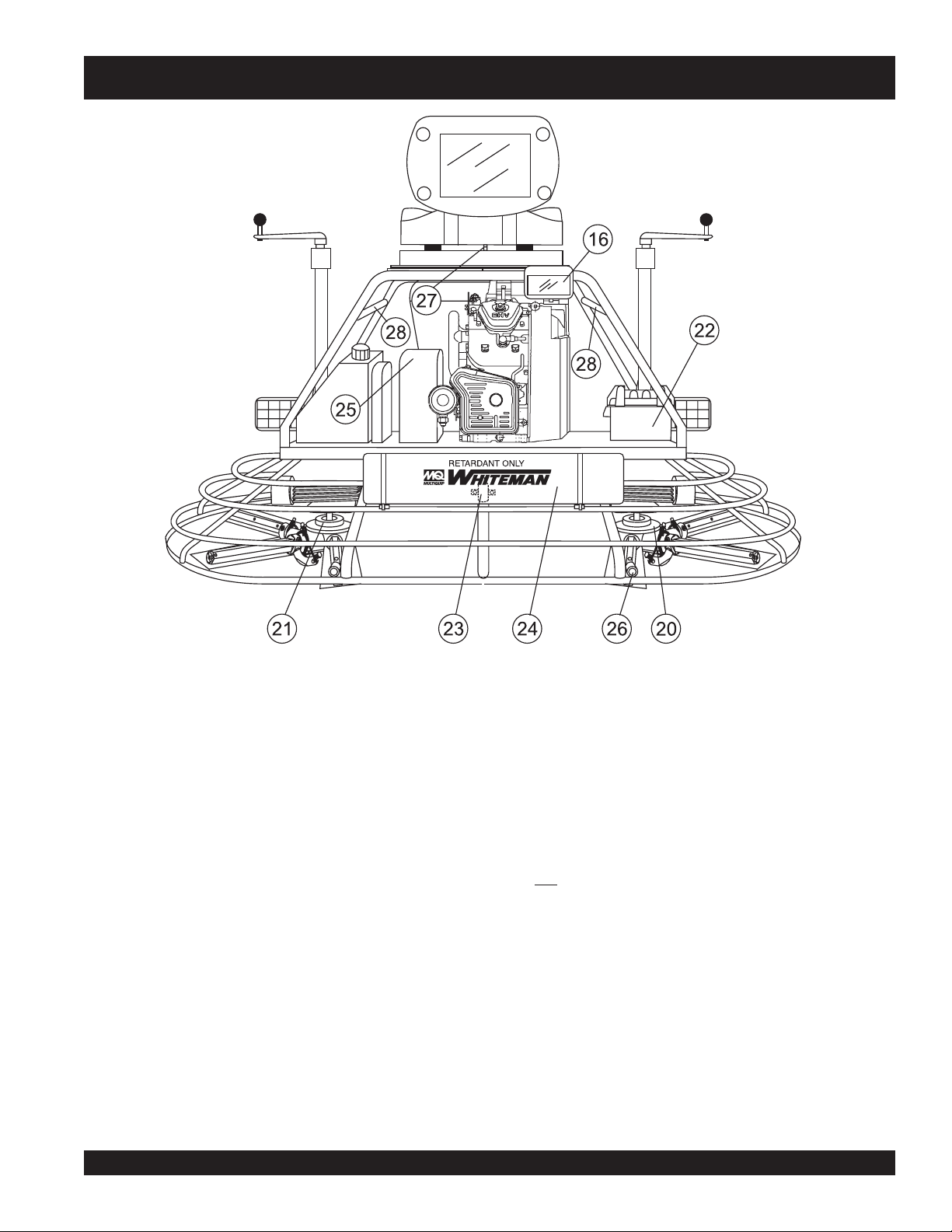
Figure 6. JTN Controls and Indicators (Rear)
20. Right-Side Spider – Consists (basic) of trowel arms,
blades, wear plate, and thrust collar etc.
21. Left-Side Spider – Consists (basic) of trowel arms, blades,
wear plate, and thrust collar etc.
22. Battery – Provides +12V DC power to the electrical system
23. Retardant Spray Motor – Used in conjunction with the
left spray control button.
24. Retardant Spray Tank – Holds 5 gallons of retardant.
25. Belt Guard – Encloses V-belts used in conjunction with
26. EZ- Mover Boss – Back- side insertion point for EZ Mover.
27. Safety Kill Switch – Shuts down engine when operator is
28. Lift Loops – Located on both the left and right sides of the
clutch.
Used when the transporting of the trowel is required.
not sitting in seat.
main frame. Used when the trowel must be lifted onto a
concrete slab.
JTN RIDE-ON TROWEL — OPERATION & PARTS MANUAL — REV. #5 (08/03/06) — PAGE 21
Page 22
JTN RIDE-ON TROWEL— NEW MACHINE SETUP INSTRUCTIONS
Trowel Pre-Set-Up Instructions
The purpose of this section is to assist the user in the setting up
NEW
of a
handles, knobs and battery, then this section can be skipped.
Before packaging and shipping this Whiteman Ride-On Power
Trowel was run and tested at the factory. If there are problems,
please let us know.
Control Handle Setup
1. Remove the bolts from the plastic bag tied to the control
2 Remove all protective wrapping and straps from the control
3. Slip the top (loose) piece into the base of the corresponding
4. Install the bolt through the lined up holes and tighten the
trowel. If your trowel is already assembled (seats,
The new ride-on trowel cannot be
put into service until the pre-setup
NOTE
towers.
handles.
handle, making sure to line up the holes.
acorn nut onto the threaded end.
installation instructions are
completed. These pre-setup
instructions only need to be
performed at the time of unpacking
NEW
a
trowel.
Seat Assembly
The seat is not installed on the trowel for shipping purposes. To
attach the seat perform the following:
1. Remove the seat from the protective wrapping.
2. Remove the bolts on the bottom of the seat, and place seat
on the seat mounting plate, then insert the bolts through
the holes or slots on the seat mounting plate and tighten.
NOTE
on tracks, similar to an automobile seat. This seat can be adjusted
fore and aft via the control lever under the front of the seat.
Battery Setup
This trowel was shipped with a wet charged battery. This battery
may need to be charged for a brief period of time as per the
manufacturer instructions.
When charging the battery, always wear
rubber gloves. Use the following rules when charging the
battery:
CAUTION:CAUTION:
CAUTION:
CAUTION:CAUTION:
There are two types of seats,
depending on what type of trowel
you have. J and H series trowels
have slots on the seat mounting
plate that allow fore and aft
adjustment of the seat. H-series
trowels have a seat that is mounted
eye
protection and
Some models are equipped with
adjustable height handles. Adjust
NOTE
the height by placing the bolt
through the set of holes that
corresponds to the most comfortable
height.
■
DO NOT expose the battery to
open flames, sparks, cigarettes
etc. The battery contains
5. Pay close attention to any wires that may be inside the
control handles. DO NOT pinch or cut any wires during
installation.
6. Inside the plastic bag of parts are two knobs for the pitch
control tower cranks. Install these two knobs onto the tower
crank levers.
combustible gases and liquids. If these gases and liquids
come in contact with a flame or spark, an explosion could
occur.
■
ALWAYS keep the battery charged. If the battery is not
charged a buildup of combustible gas will occur.
To install the battery on the trowel, make sure that the
■
ALWAYS keep battery charging and cables in good working
battery is well seated in the battery box and the
condition. Repair or replace all worn cables.
terminals are properly connected. Close the plastic
battery box cover and secure the battery box.
■
ALWAYS recharge the battery in an vented air environment,
to avoid risk of a dangerous concentration of combustible
gases.
PAGE 22 — JTN RIDE-ON TROWEL— OPERATION & PARTS MANUAL — REV. #5 (08/03/067)
Page 23
JTN RIDE-ON TROWEL — INITIAL START-UP
This section is intended to assist the operator with
the initial start-up of the JTN ride-on trowel. It is
extremely important that this section be read
carefully before attempting to use the trowel in
the field.
DO NOT use your ride-on power trowel until this section is
thoroughly understood.
CAUTION:CAUTION:
CAUTION:
CAUTION:CAUTION:
Failure to understand the operation of the JTN
Ride-On Trowel could result in severe damage
to the trowels or personal injury.
See Figures 5 and 6 for the location of any control or indicator
referenced in this manual.
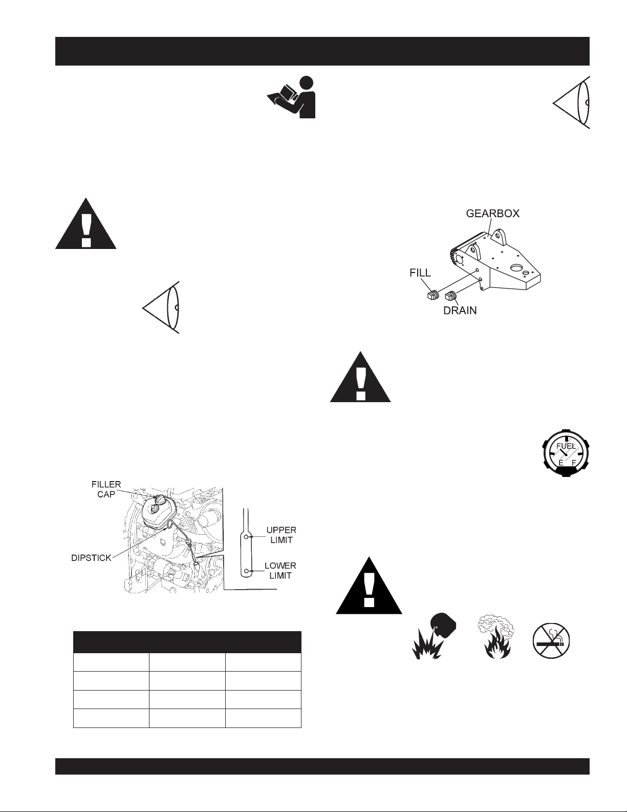
Engine Oil Level
1. To check the engine oil level, place the trowel on secure
level ground with the engine stopped.
2. Remove the dipstick from its holder as shown in Figure 7
and wipe clean.
3. Insert and remove the dipstick into the holder. Check the oil
level shown on the dipstick.
4. If the oil level is low (Figure 7), fill to the correct operating
level with the recommended oil type as listed in Table 3.
See Table 2 for engine oil capacity.
Gearbox Oil Level
1. Check the gearbox oil level in both gearboxes
by removing the plug located on the side of the
gearbox. See Figure 8.
2. The level of oil in the gearbox should just reach the bottom
of the fill plug hole. The fill hole plug is located approximately
half way up the side of the gearbox. If needed, refill with
specially formulated Whiteman gearbox lubricant P/N
10139 or ISO 680 oil. Gearbox oil capacity is 27 oz. (.798
liters).
CAUTION:CAUTION:
CAUTION:
CAUTION:CAUTION:
Fuel
1. Determine if the engine fuel is low. If fuel level
is low, remove the fuel filler cap and fill with
unleaded gasoline. Handle fuel safely. Motor
fuels are highly flammable and can be
dangerous if mishandled. DO NOT smoke while refueling.
DO NOT attempt to refuel the ride-on trowel if the engine is
hot or running.
Figure 8. Gearbox Oil Plugs
Use caution when removing plugs on the
gearbox, there are two of them. Removal of
the bottom most plug (
the oil in the gearbox.
drain plug
) will drain
DANGER:DANGER:
DANGER:
DANGER:DANGER:
Figure 7. Engine Oil Dipstick
epyTliO.3elbaT
nosaeS erutarepmeT epyTliO
remmuS rehgiHroC°52 03-W01EAS
llaF/gnirpS C°01~C°52 02/03-W01EAS
retniW rewoLroC°0 01-W01EAS
JTN RIDE-ON TROWEL — OPERATION & PARTS MANUAL — REV. #5 (08/03/06) — PAGE 23
ALWAYS
gasoline.
expansion.
The fuel tank cap must be closed tightly after filling. Handle
fuel in a safety container. If the container does not have a
spout, use a funnel. Wipe up any spilled fuel immediately.
fill the fuel tank with clean and fresh unleaded
DO NOT over fill fuel tank. Leave room for
Fuel spillage on a
a
fire
or
explosion
wipe up the spilled fuel completely to
prevent fire hazards.
around or near the generator.
hot!
engine can cause
. If fuel spillage occurs,
NEVER!
smoke
Page 24
JTN RIDE-ON TROWEL — INITIAL START-UP
Starting the Engine (Honda)
1. With one foot on the ground and the other foot placed on
the trowel’s platform, grab hold of any part of the frame and
lift yourself onto the trowel. Then sit down in the operator’s
seat.
2. The MQ Whiteman JTN ride-on trowel is equipped with a
kill switch
safety
assembly. Remember the engine will not start unless an
operator is sitting in the operator’s seat. The weight of an
operator depresses an electrical switch, which will allow
the engine to start.
CAUTION:CAUTION:
CAUTION:
CAUTION:CAUTION:
3. It is recommended that the
engine after every use. Doing this will verify that the switch
is working properly and presents no danger to the operator.
Remember to turn the key to the “OFF” position after
stopping the trowel. Not doing so may drain your units’
battery.
4. The right foot pedal (Figure 9) controls blade and engine
speed. The position of the foot pedal determines the blade
speed. Slow blade speed is obtained by slightly depressing
the pedal. Maximum blade speed is obtained by fully
depressing the pedal.
. This switch is located beneath the seat
NEVER disable or disconnect the kill switch. It
is provided for the operator's safety and injury
may result if it is disabled, disconnected or
improperly maintained.
kill switch
be used to stop the
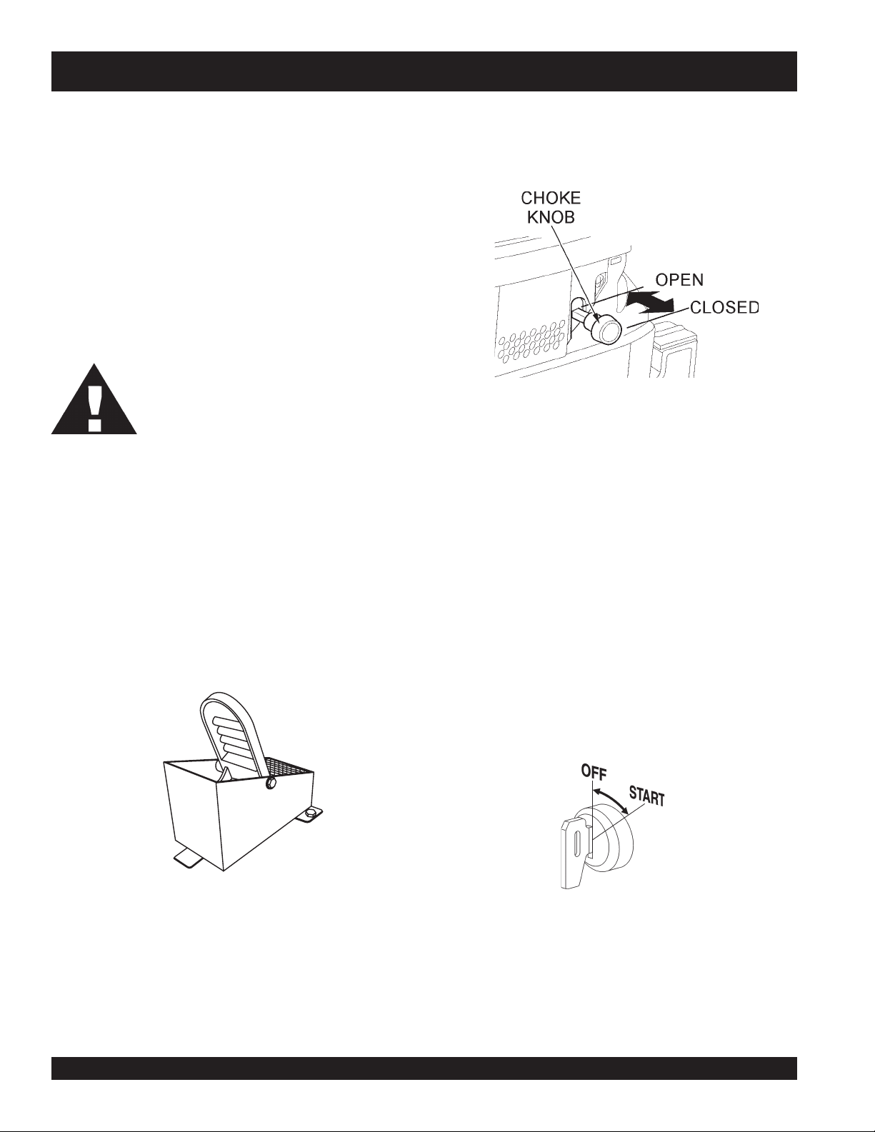
5. When starting a cold engine, pull the choke knob (Figure 10)
out to the
engine is warm, the unit can be started with choke halfway
or completely
6. Keep your foot OFF the gas pedal (right foot pedal). If the
engine is cold, adjust the choke but in all circumstances,
start the engine at idle (without touching the gas pedal).
7. Insert the
8. Turn the ignition key (Figure 11) clockwise and listen for
the engine to start. Once the engine starts release ignition
key.
9. If the engine fails to start in this manner, consult the engine
owner's manual supplied with the trowel.
10. Test the safety "kill switch" by standing up briefly. The switch
under the seat should cause the engine to stop. If the "kill
switch" fails to shut down the engine. Turn off the engine
with the key switch and fix the safety "kill switch". See Table 6
(Troubleshooting ) for possible problems.
close
position. In warm weather or when the
open
.
Figure 10. Choke Knob
ignition key
into the ignition switch.
11. Repeat this section a few times to get fully acquainted with
the engine starting procedure.
Figure 9. Blade Speed Control Foot Pedal
Figure 11. Ignition Switch/Key
PAGE 24 — JTN RIDE-ON TROWEL— OPERATION & PARTS MANUAL — REV. #5 (08/03/067)
Page 25

JTN RIDE-ON TROWEL — INITIAL START-UP
Steering
Two control levers located in front of the operator’s seat provide
directional control for the trowel. Table 4 below illustrates the
various directional positions of the control levers and their effect
on the ride-on trowel.
All directional references with
NOTE
respect to the steering control
levers are from the
operator’s
seat
position.
Figure 12. Left and Right Control Levers
1. Push both the left and right control levers forward. See
Figure 12.
2. With your right foot quickly depress the right foot pedal
halfway. Notice that the ride-on power trowel begins to move
in a forward direction. Return both joystick controls to their
neutral position to stop forward movement, then remove
your right foot from the right foot pedal.
3. Practice holding the machine in one place as you increase
blade speed. When about 75% of maximum blade speed
has been reached, the blade will be moving at proper
finishing speed. The machine may be difficult to keep in
4. Practice maneuvering the ride-on trowel using the
information listed in Table 4. Try to practice controlled
motions as if you were finishing a slab of concrete. Practice
edging and covering a large area.
5. Try adjusting the pitch of the blades. This can be done with
the ride-on trowel stopped or while the trowel is moving,
whatever feels comfortable. Test the operation of optional
equipment like retardant spray and lights if equipped.
6. Push both the left and right joysticks backward and repeat
steps 3 through 6 while substituting the word reverse for
forward.
one place. Trying to keep the ride-on trowel stationary is a
good practice for operation.
NOTE
REVELLORTNOC NOITCERID STLUSER
tfeL
reveLlortnoCevoM
drawroF
It is strongly suggested that all
operators (experienced and novice)
Slabs on Grade
read “
” published
by the American Concrete Institute,
Detroit Michigan.
gninoitisoPlanoitceriDreveLlortnoC.4elbaT
otlewortno-edirehtsesuaC
.thgirehtotdnadrawrofevom
tfeL
thgiR
thgiR
thgiRdnatfeL
thgiRdnatfeL
thgiRdnatfeL
thgiRdnatfeL
reveLlortnoCevoM
drawkcaB
reveLlortnoCevoM
drawroF
reveLlortnoCevoM
drawkcaB
htoBevoM
drawroFsreveLlortnoC
htoBevoM
drawkcaBsreveLlortnoC
htoBevoM
thgiRehtotsreveLlortnoC
htoBevoM
tfeLehtotsreveLlortnoC
otlewortno-edirehtsesuaC
.tfelehtotdnadrawkcabevom
otlewortno-edirehtsesuaC
.tfelehtotdnadrawrofevom
otlewortno-edirehtsesuaC
.thgirehtotdnadrawkcabevom
lewortno-edirehtsesuaC
nidrawrofevomot
.enilthgiartsa
lewortno-edirehtsesuaC
drawkcabevomot
.enilthgiartsani
lewortno-edirehtsesuaC
.thgirehtotevomot
lewortno-edirehtsesuaC
tfelehtotevomot
JTN RIDE-ON TROWEL — OPERATION & PARTS MANUAL — REV. #5 (08/03/06) — PAGE 25
Page 26
JTN RIDE-ON TROWEL— MAINTENANCE
Use Table 5 as a general guideline when servicing of the engine is
required.
TSRIF
)3(NOITPIRCSEDNOITAREPOEROFEB
liOenignE
renaelCriA
stloB&stuNllA
gulPkrapS
sniFgnilooCKCEHCX
retserrAkrapSNAELC X
knaTleuFNAELC X
retliFleuFKCEHC X
deepSeldITSUJ
ecnaraelCevlaVTSUJDA-KCEHC )2(X
seniLliO/leuFKCEHC )2()yrassecenfiecalper(sraey2yrevE
KCEHCX
EGNAHCX
KCEHCX
EGNAHC)1(X
fInethgit-eR
yrasseceN
ECALPER X
DA-KCEHC )2(X
wyltneuqerferomecivreS)1( YTSUD .saera
ecivresebdluohssmetiesehT)2(
X
NAELC-KCEHCX
nidesuneh
HTNOM
RO
eludehcSecnanetniaMenignE.5elbaT
YREVE
SHTNOM3
RO
.SRH01
.SRH52
YREVE
SHTNOM6
RO
.SRH05
.slavretniecnanetniamreporpenimretedotnoitarepofosruohgol,esulaicremmocroF)3(
YREVE
RAEY
RO
01
.SRH0
serudecorpecivresroflaunaMpohsnottartSdnasggirBroADNOHehtotrefeR.tneiciforp
YREVE
SRAEY2
RO
.SRH002
yllacinahcemeradnaslootreporpehtevahuoysselnu,relaedcivresruoyybd
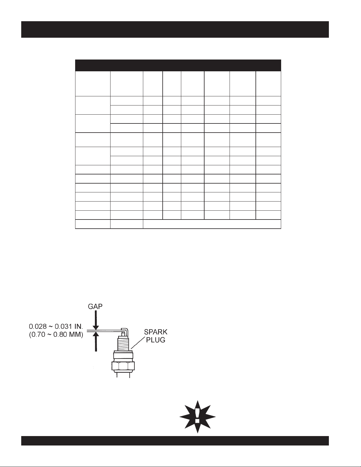
Spark Plug (100 Hours)
1. Inspect the spark plug every 100 hours, replace plug if the
electrodes are worn, or if the insulator is cracked or chipped.
Clean the spark plug with a wire brush, if plug is to be
reused.
Engine Maintenance Schedule (Daily)
Daily (8-10 Hours)
■
Check the oil level in the engine crankcase and gear box, fill
as necessary.
■
Check V-belt.
Long Term Storage
■
Drain fuel from fuel tank, fuel line and carburetor.
■
Remove spark plug and pour a few drops of motor oil into
cylinder. Crank engine 3 to 4 times so that oil reaches all
internal parts.
■
Clean exterior with a cloth soaked in clean oil.
■
Store unit covered with plastic sheet in moisture free and
Figure 13. Spark Plug
2. For Honda engines adjust the spark gap (Figure 13) to
dust free location out of direct sunlight.
CAUTION:CAUTION:
CAUTION:
CAUTION:CAUTION:
0.028~0.031 inch (0.70~0.78 mm). For Vanguard engines
adjust spark gap to 0.030 inch (76 mm). Both engines have
electronic ignition, which requires no adjustments. Replace
spark plug every 300 hours.
NEVER store the ride-on trowel with fuel in the
tank for any extended period of time. ALWAYS
clean up spilled fuel immediately.
PAGE 26 — JTN RIDE-ON TROWEL— OPERATION & PARTS MANUAL — REV. #5 (08/03/067)
Page 27
JTN RIDE-ON TROWEL— MAINTENANCE
Maintenance
Perform the scheduled maintenance procedures as indicated:
DAILY
■
Thoroughly remove dirt and oil from the engine and control
area. Clean or replace the air cleaner elements as necessary.
Check and retighten all fasteners as necessary.
Air Cleaner (Daily)
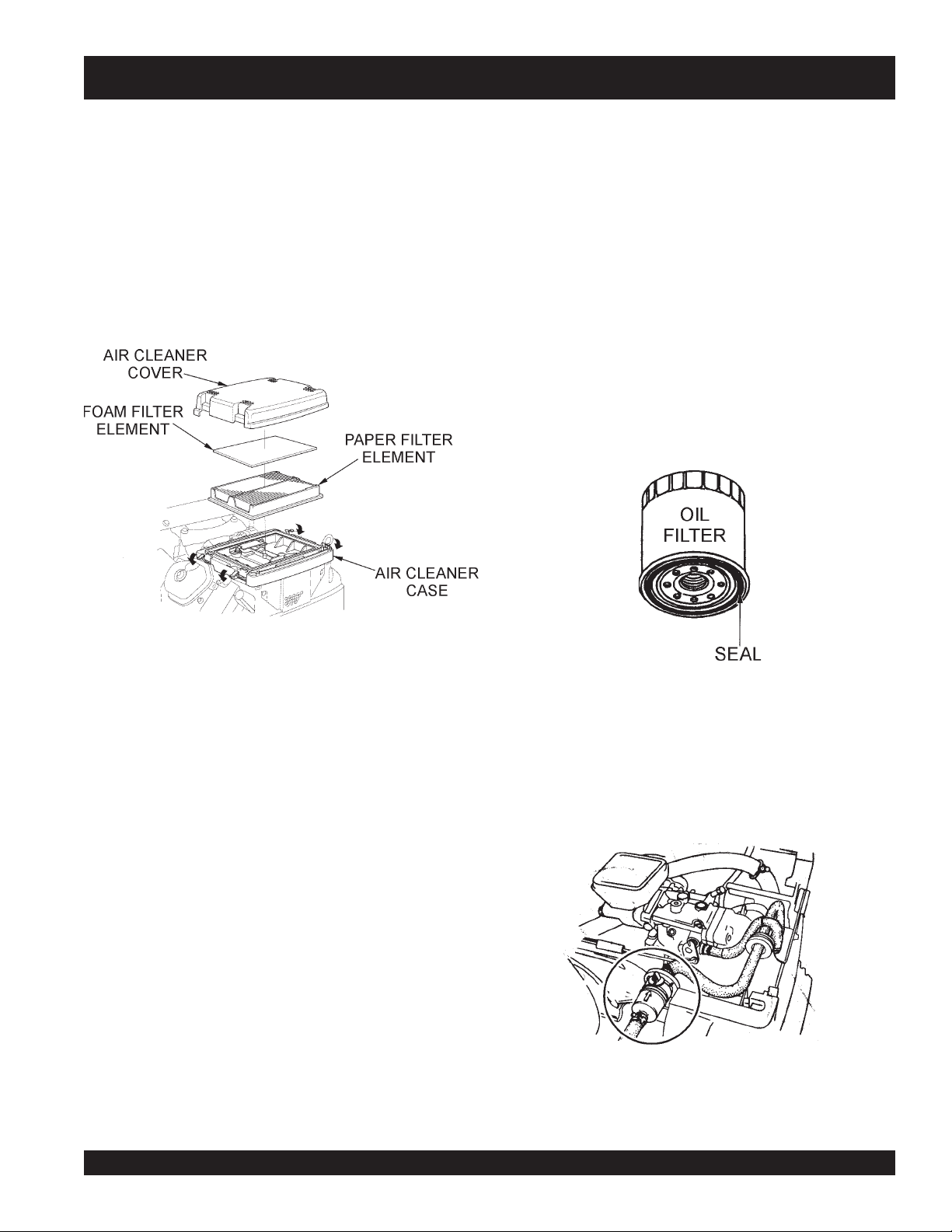
1. Release the four latch tabs (Figure 14) from the air cleaner
cover, and remove the cover.
9. Reinstall the foam air filter element to the air cleaner cover,
then reinstall the paper air filter element and cover to the
air cleaner case. Securely latch the four hook tabs on the
air cleaner cover
Changing Engine Oil (100 Hours)
1. Change the engine oil after the first 20 hours of use, then
change every 6 months or 100 hours.
2. Remove the oil filler cap and fill engine crankcase with
recommended type oil as listed in Table 3. Fill to the upper
limit of dipstick.
3. Fill crankcase with oil. Reference Table 2 for crankcase oil
capacity.
Oil Filter (200 Hours)
1. Replace the engine oil filter (Figure 15) every 200 hours.
Figure 14. Air Cleaner
2. Remove the foam filter from the cover.
3. Remove the paper filter from the air cleaner case.
4. Inspect both air filter elements, replace them if necessary.
5. To clean the paper air filter, tap the filter element several
times on a hard surface to remove dirt, or blow compressed
air (not to exceed 30 psi (207 kPa, 2.1 kgf/cm
filter element from the air cleaner case side.
NEVER!
6.
fibers. If the paper element is excessively dirt, replace
element.
7. Clean the
rinse and allow to dry thoroughly. Or clean with a
nonflammable solvent and allow to dry. DO NOT pour any
type of oil into the foam element.
8. Wipe dirt from the inside of the air cleaner body and cover,
using a moist cloth. Be careful not to let any dirt or debris to
enter the air chamber that leads to the carburetor.
try to brush off dirt; brushing will force dirt into the
foam air filter element
in warm soapy water,
2
) through the
Figure 15. Oil Filter
2. Be sure to coat the
engine oil.
Fuel Filter (200 Hours)
1. Replace the engine fuel filter (Figure 16) every 200 hours.
Figure 16. Fuel Filter
seal
of the new oil filter with clean
JTN RIDE-ON TROWEL — OPERATION & PARTS MANUAL — REV. #5 (08/03/06) — PAGE 27
Page 28
JTN RIDE-ON TROWEL— MAINTENANCE
Belt Changing Procedure
The belts need to be changed as soon as they show signs of
wear. Remember that all belts should be changed at the same
time. Do not reuse a belt under any circumstances. Indications of
excessive belt wear are fraying, squealing when in use, belts
that emit smoke or a burning rubber smell when in use.
Under normal operating conditions, a set of belts may last
approximately six months. If you trowel is not reaching this kind
of life span for belts, there are some things to check when you
replace a set of belts.
Check to ensure that the belts are tensioned correctly. Next, check
to make sure that the lower drive pulley (Figure 17) is aligned
properly.
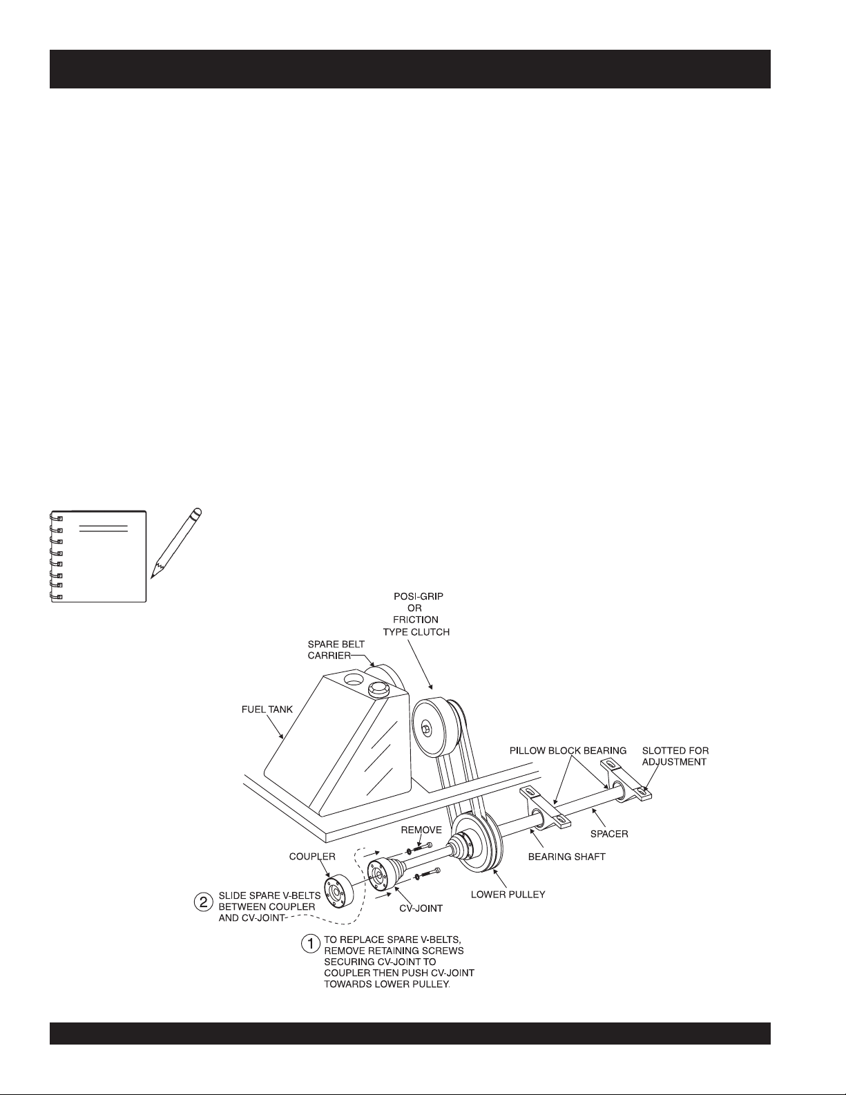
Your machine is equipped with a spare belt carrier (Figure 17). It
is located opposite the clutch, mounted on the fuel tank. Make
sure that there are belts in the carrier before the trowel is placed
on a slab to finish concrete.
To install new belts from the spare belt carrier, first cut off the old
belts. Next, remove the spare belt carrier by unscrewing the two
bolts that attach it to the fuel tank.
NOTE
Make sure that there are belts in
the belt carrier before the trowel is
placed on a slab to finish concrete.
The next step is to loosen the four engine mounting bolts and
slide the engine toward the rear of the trowel. Slide the first belt
over the clutch and place it on the upper drive pulley, then pull it
down and place it on the lower drive pulley. Repeat this procedure
for the second belt.
Realign the engine as described in the Belt Tension
Adjustment Procedure, and replace the belts in the spare belt
carrier.
Replacing Spare Belts
.
After the spare set of belts has been installed on the clutch pulley,
it will be necessary to replace the spare set of belts that were in
the spare belt carrier.
To replace a spare set of belts, be prepared to disassemble the
driveline
The driveline is located directly under the spare belt carrier.
There are three bolts that need to be removed that will disconnect
the CV-joint from the gearbox coupler. See Figure 17.
Once the CV-joint has been separated from the gearbox coupler,
.
push the CV-joint inward so that a gap exist between the coupler
and the CV-joint. Slide the replacement belts between this gap,
and place them onto the spare belt carrier. Secure the spare belt
carrier to the fuel tank.
.
Figure 17. Belt Changing Diagram
PAGE 28 — JTN RIDE-ON TROWEL— OPERATION & PARTS MANUAL — REV. #5 (08/03/067)
Page 29
JTN RIDE-ON TROWEL — MAINTENANCE
See the engine manual supplied
with your trowel for appropriate
NOTE
engine maintenance schedule and
troubleshooting guide for problems.
At the front of this manual there is a “
Checklist
basis.
CAUTION!CAUTION!
CAUTION!
CAUTION!CAUTION!
Trowel Maintenance Schedules
Weekly (50-60 Hours)
■
Relube arms, thrust collar and clutch.
■
Replace blades if necessary.
”. Make copies of this checklist and use it on a daily
ALWAYS allow the engine to
cool before servicing. NEVER
attempt any maintenance
hot!
work on a
engine.
Daily Pre-Operation
Trowel Arm Adjustment Procedure
The following procedure should be
followed to adjust trowel arms when
NOTE
level
, clean area to test the trowel prior to and after is essential.
A
spots
Any uneven
will give an incorrect perception of adjustment. Ideally, a 5 x 5"
three-quarter inch thick
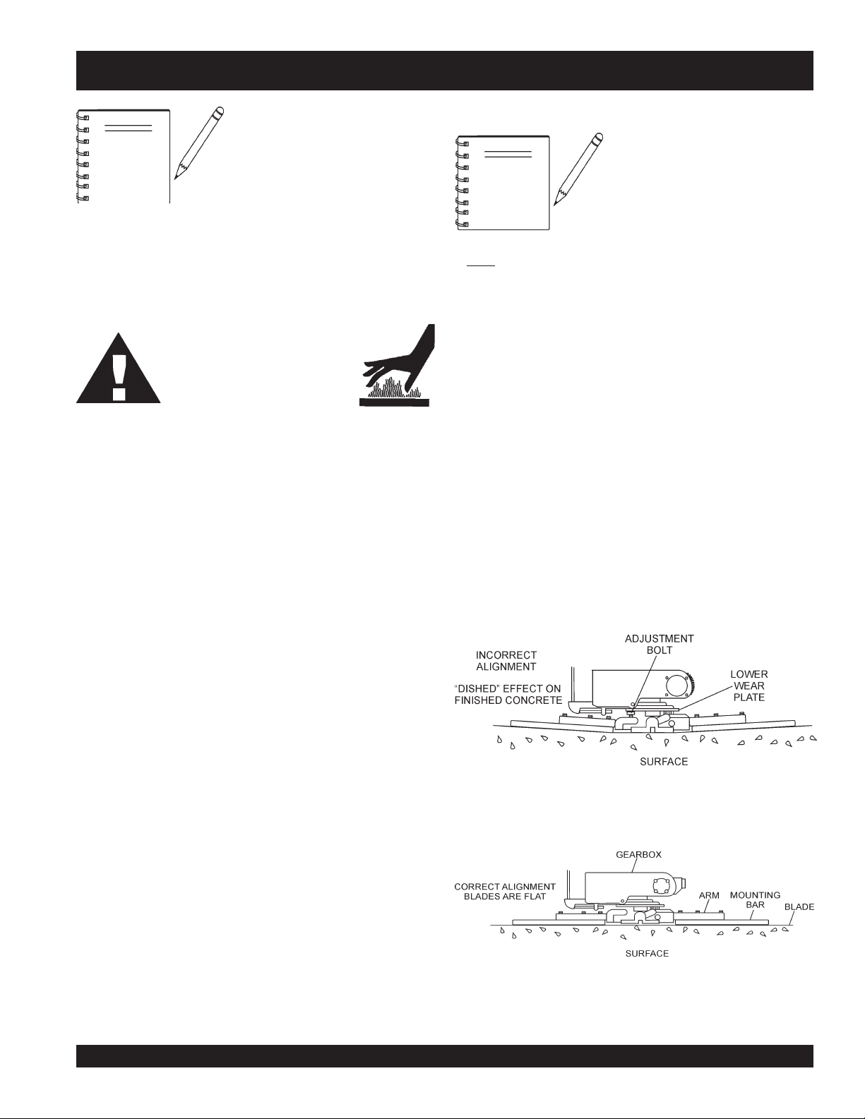
To determine which blades need adjustment, place the trowel in
the test area (three-quarter inch thick plate) and look for the
following conditions:
■
Pitch the blades as flat as possible and look at the
adjustment bolts
with the
that one of them is not making contact, some adjustment
will be necessary.
■
Is the machine wearing out blades unevenly (i.e. one
blade is completely worn out while the others look new)?
in the floor or debris under the trowel blades
lower wear plate
it becomes apparent that the trowel
is finishing poorly or in need of
routine maintenance.
flat
steel plate should be used for testing.
. They should all barely make contact
on the spider. If you can see
Figure 18 below illustrates a "
Monthly (200-300 Hours)
■
Remove, clean, reinstall and relube the arms and thrust collar.
Adjust the blade arms.
■
Remove, clean, reinstall clutch.
Yearly (2000-2500 Hours)
■
Check and replace if necessary the arm bushings, thrust
collar bushings and shaft seals.
■
Check pitch control cables for wear.
■
Adjust blade speed.
trowel arms
touching (0.10" max. clearance) lower wear plate. All alignment
bolts should be spaced the same distance from the lower wear
plate.
Figure 19 below illustrates the "
plate (as shipped from the factory).
worn spider bushings or bent
". Check to see that adjustment bolt is barely
Figure 18. Worn Spider Plate
correct alignment
" for a spider
Figure 19. Correct Spider Plate Alignment
JTN RIDE-ON TROWEL — OPERATION & PARTS MANUAL — REV. #5 (08/03/06) — PAGE 29
Page 30
JTN RIDE-ON TROWEL — MAINTENANCE
2. Start engine, and bring trowel blades up to full speed and look
b. Loosen the jam nut and cone point square head set
for the following conditions:
■
Does the trowel have a perceived rolling or bouncing
motion when in use?
■
Look at the trowel while it is running, does the guard
ring “rock up and down” relative to the ground?
Spider Removal
c. If the trowel is equipped with an outer stabilizer ring
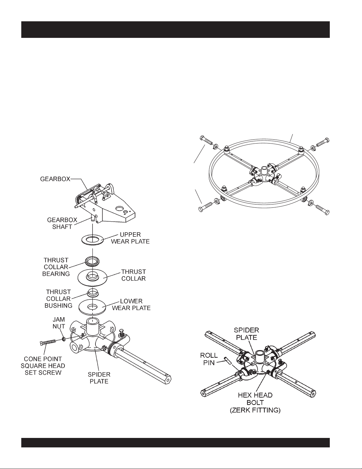
1. Once it is determined that an adjustment is required, remove
the spider assembly from the gearbox shaft as follows:
a. Locate the cone point square head set screw (Figure 20)
and attached jam nut found on the side of the spider
assembly.
REMOVE
TO FREE
SPIDER
ASSEMBLY
screw, and carefully lift the
upper trowel assembly
off
of the spider assembly. A slight tap with a rubber mallet
may be necessary to dislodge the spider from the main
shaft of the gearbox.
(Figure 21), remove the four bolts at the end of each
spider arm.
STABILIZER
RING
Figure 20. Stabilizer Ring
d. Examine stabilizer ring for out of round or bends. If ring
is damaged, replace ring. If ring is found to be correct with
no damage, set aside.
Trowel Arm Removal
1. Each trowel arm is held in place at the spider plate by a hex
head bolt (zerk grease fitting) and a roll pin. Remove both the
hex head bolt and the roll pin (Figure 22) from the spider
plate.
2. Remove the trowel arm from the spider plate.
Figure 20. Spider/Gearbox Removal
Figure 22. Removing Roll Pin
and Zerk Grease Fitting
PAGE 30 — JTN RIDE-ON TROWEL— OPERATION & PARTS MANUAL — REV. #5 (08/03/067)
Page 31

JTN RIDE-ON TROWEL — MAINTENANCE
3. Should the trowel arm inserts (bronze bushing ) come out
with the trowel arm, remove the bushing from the trowel arm
and set aside in a safe place. If the bushing is retained inside
the spider plate, carefully remove the bushing.
4. Examine the bronze trowel arm bushing insert (Figure 23),
clean if necessary. Replace bushing if out-of-round or worn.
Figure 23. Bronze Bushings
Trowel Blade Removal
1. Remove the trowel blades from the trowel arm by removing
the three hex head bolts (Figure 24) from the trowel arm. Set
blades aside.
Trowel Arm Flatness Test
1. Using a piece of 3/4 inch thick steel plate or any surface which
true
is
flatness.
2. Check each of the six sides of the trowel arm (hex section
only) using a ten thousands of an inch (max.) feeler gauge
(Figure 25) between the flat of the trowel arm and an
tremely flat
and
flat
, check all
test surface.
six sides
of each trowel arm for
ex
-
Figure 24. Trowel Blades
Wire brush
2.
trowel arm. Repeat this for the remaining three arms.
any build-up of concrete from all six sides of the
Figure 25. Trowel Arm Flatness Test
3. If the trowel arm is found to be
trowel arm. A bent trowel will not allow the trowel to operate
in a smooth fluid rotation.
4. Next, check each of the six sides of the round machined shaft
section of the trowel arm. Each section should have the
clearance
test surface.
between the round of the trowel arm shaft and the
uneven
or
bent
, replace the
same
Trowel arms can be damaged by
NOTE
rough handling or by striking
exposed plumbing or forms while in
operation.
ALWAYS
look-out for
objects which might cause damage
to the trowel arms.
JTN RIDE-ON TROWEL — OPERATION & PARTS MANUAL — REV. #5 (08/03/06) — PAGE 31
Page 32

JTN RIDE-ON TROWEL — MAINTENANCE
Trowel Arm Adjustment
Shown in Figure 26 is the adjustment fixture with a trowel arm
inserted. As each trowel arm is locked into the fixture, the arm bolt
is adjusted to where it contacts a stop on the fixture. This will
consistently adjust all of the trowel arms, keeping the finisher as
flat and evenly pitched as possible.
1. Locate the trowel arm adjustment tool P/N 9177. Set the
adjustment tool for a clock-wise blade rotation, meaning the
fixture arm is in the "UP" position.
3. Un-screw the locking bolts on the adjustment tool, and place
the trowel arm into the adjustment fixture channel as shown
in Figure 34. A
holes on the trowel arm. Make sure to align the trowel
adjustment bolt with the fixture adjustment bolt.
4. Using an allen wrench, tighten the locking bolts on the
adjustment tool and securely lock the trowel arm in place.
5. Loosen the locking nut on the trowel arm lever, then turn the
trowel arm adjusting bolt until it barely touches (.010") the
adjusting bolt on the fixture.
6. After the correct adjustment has been made, tighten lock nut
on trowel arm lever to lock in place.
7. Loosen locking bolts on adjustment fixture, and remove
trowel arm from fixture.
8. Repeat steps 2-7 for the remaining trowel arms.
Re-Assembly
1. Clean and examine the upper/lower wear plates and thrust
collar. Examine the entire spider assembly. Wire brush any
concrete or rust build-up. If any of the spider components are
found to be damaged or out of round, replace them.
thin shim
may be required to cover the blade
2. Make sure that the bronze trowel arm bushing is not damage
3. Reinstall bronze bushing onto trowel arm.
4. Repeat steps 2 -3 for each trowel arm.
5. Make sure that the spring tensioner is in the correct position
6. Insert all trowel arms with levers into spider plate (with bronze
7. Lock trowel arms in place by tightening the hex head zerk
Figure 26. Trowel Arm Adjustment Tool
2. Trowels manufactured prior to June of 1982 require that the
distance from the end of the adjusting bolt and the fixture arm
must be 7/8" (Figure 26). Conversely, trowels manufactured
after June of 1982 require that the distance from the end of
the adjusting bolt and the fixture arm must be 1/2".
8. Re-install the blades back onto the trowel arms
8. Install stabilizer ring onto spider assembly.
9. Reinstall lower wear plate,
or out of round. Clean the bushing if necessary. If the bronze
bushing is damage or worn, replace it.
to exert tension on the trowel arm.
bushing already installed) using care to align grease hole on
bronze bushing with grease hole fitting on spider plate.
grease fitting and jam nut.
thrust collar
in the
ring
the spider shaft. Make sure that there is little or no lateral
movement between the thrust collar and the spider shaft.
reverse order
that they were dis-assembled onto
and
upper wear
PAGE 32 — JTN RIDE-ON TROWEL— OPERATION & PARTS MANUAL — REV. #5 (08/03/067)
Page 33

JTN RIDE-ON TROWEL — TROUBLESHOOTING (TROWEL)
)LEWORT(GNITOOHSELBUORT.6ELBAT
MOTPMYS MELBORPELBISSOP NOITULOS
?noitcnuflamhctiwslliK
.lla
tatonrohguorgninnurenignE
?leuF
?noitingI
?smelborprehtO .launams’rerutcafunamenignetlusnoC
.gninoitcnuftonhctiwsllikytefaS
?stcatnocdaB .hctiwsecalpeR
?sedalB
?redipS
?snoitcennoceriwesooL .yrassecensaecalpeR.gniriwkcehC
?smraleworttneB
.yltcerrocgninoitcnuf
.yrassecenfihctiwsecalper;detaes
.rabedalbehtotlellarapdna
.yletaidemmitiecalper,tnebylthgilsnevesismra
sirotarepoehtnehwgninoitcnufsihctiwsllikehttahterusekaM
otdeilppusgniebleufsierehterusekaM.metsysleufehttakooL
.deggolctonsiretlifleufehttahterusneotkcehC.enigneeht
sidnarewopsahhctiwsnoitingiehttahterusneotkcehC
.nrowylevissecxeton,noitidnocdoognierasedalbniatrecekaM
ehtmorf)mm05("2nahtsselonerusaemdluohssedalbhsiniF
onerusaemdluohssedalbobmoc,egdegniliartehtotrabedalb
thgiartsebdluohsedalbfoegdegniliarT.)mm98("5.3tahtssel
saelgnahctipemasehttateserasedalbllatahtkcehC
rofelbaliavasiloottnemtsujdadleifA.redipsehttaderusaem
.)tnempiuqElanoitpOees(smralewortehtfotnemtsujdathgieh
ehtfoenofI.smraleworttnebrofylbmessaredipsehtkcehC
sllor,secnuob“lewortfI
nevenusekamro,etercnoc
.”etercnocnislriws
?ralloctsurhT
?hctipedalB
?tfahsniaM
elbitpecrepasahenihcaM
.gninnurelihwnoitomgnillor
?ekoY
?sgnihsubmraleworT
?gnihsubralloctsurhT
?nrowgniraebtsurhT
om
.ralloctsurhtehtnignihsubehtecalper
.eerfgninnipssititahteesotgniraebtsurhtehtkcehC
.yrassecenfiecalpeR
.yrassecenfisnoitcurtsni
.tnioptnemhcatta
.yrassecensaekoyecalpeR.pacraeweht
ybenodebnacsihT.ssenthgitrofsgnihsubmralewortehtkcehC
"8/1nahteromsierehtfI.nwoddnapusmralewortehtgniv
ebdluohssgnihsubeht,mraehtfopitehttalevartfo)mm2.3(
.emitemasehttadecalperebdluohssgnihsubllA.decalper
.redipsehtnotignitatorybralloctsurhtehtfossentalfehtkcehC
.ralloctsurhtehtecalper)mm5.0("20.0nahteromybseiravtifI
tlitnactifI.redipsehtnotignikcorybralloctsurhtehtkcehC
,].D.Oralloctsurhtehttaderusaemsa[)mm6.1("61/1nahterom
noitcesecnanetniaMreptsujdA.hctiptnetsisnocrofsedalbkcehC
ebdluohsylbmessaxobraegehtfotfahstuptuoniamehT
dnathgiartsnurtsumtfahsniamehT.ssenthgiartsrofdekcehc
redipsehttadnuorfotuo)mm80.0("300.0nahteromebtonnac
noylnevesserpekoyehtfosregnifhtobtahterusekamotkcehC
JTN RIDE-ON TROWEL — OPERATION & PARTS MANUAL — REV. #5 (08/03/06) — PAGE 33
Page 34

JTN RIDE-ON TROWEL — TROUBLESHOOTING (TROWEL)
)LEWORTDEUNITNOC(GNITOOHSELBUORT.6ELBAT
MOTPMYS MELBORPELBISSOP NOITULOS
?gniriW
.gnikrowton)lanoitpo(sthgiL
?sthgiL .nekorbfiecalpeR.doogllitserasblubthgilfieesotkcehC
?tnadrateR
?gniriW
ton)lanoitpo(yarpstnadrateR
.gnikrow
?hctiwsdaB
?pmupyarpsdaB
?tnemtsujdafotuodeepsedalB
?stnenopmocnroW
otkcehcdna
.yrassecensaecalpeR
.yrassecen
.pmupehtecalper,doog
.tnemtsujdadeepsedalbnonoitceseeS
.yrassecenfiecalper
hctiwsffo/noretsamehtgnidulcni,snoitcennoclacirtcelellakcehC
.strohsonhtiwnoitidnocdoognisigniriwfiees
saknatlliF.tneserpsitnadratererusekamotknatehtkcehC
hctiwsffo/noretsamgnidulcni,snoitcennoclacirtcelellakcehC
.yrassecensagniriwdnastnenopmocecalpeR.snoitcennoc
.nekorbfiecalpeR.hctiwsffo/noretsamfoytiunitnocehtkcehC
tub,nodenrutsihctiwsehtnehwtneserpegatlovasahpmupfI
erapmupehtotsnoitcennoclacirtcelednaetarepotonseod
stnenopmocegaknildnasgniraebgnireetsforaewrofkcehC
.evisnopsernusignireetS
?stoviP
?erusserpciluardyH
sinoitisopgnitarepO
.elbatrofmocnu
hctiPcirtcelEnodaehrewoP
.gnikrowton)lanoitpo(
)lanoitpo(hctiPniwTnoegakniL
.gnikrowton
?gniriW
?hctiwS
?seldnahknarC
?trapnekorB
?rotareporoftsujdataeS
?strapesoolronekorB
wop
.ecivresrof
.yletaidemmiecalper
.erusserpciluardyhgnikcehcno
.yletaidemmistrapnekorbllaecalpeR
.srotomevirdciluardyhfotnemevomeerferusneotkcehC
noitceseeS.etauqedasierusserpciluardyhtahterusneotkcehC
.taesehtfotnorfehtnodetacolrevelhtiwtaestsujdA
ehtedisnistrap,detceffatonsihctipehtdnasnurrotomehtfI
relaedotdaehrewopnruteR.nekorbroesoolebyamdaehre
ytiunitnocehtkcehC.gniriwdnasnoitcennoclacirtcelellakcehC
ehttatneserpegatlovsierehttahtyfireV.tinudaehrewopehtta
.noitisop”no“ehtnihctiwsyekehthtiwhctiwsdaehrewop
,gninoitcnuflamsihctiwsfI.hctiwsehtfoytiunitnocehtkcehC
sarafsanwoddehsuperaseldnahknarchtobtahterusekaM
.degagnesiegaknilehttahtserusnesihtgnioD.elbissop
PAGE 34 — JTN RIDE-ON TROWEL— OPERATION & PARTS MANUAL — REV. #5 (08/03/067)
Page 35

JTN RIDE-ON TROWEL — TROUBLESHOOTING (ENGINE)
MOTPMYS MELBORPELBISSOP NOITULOS
tratsottluciffiD
?egdirbgniebgulpnoitingI .metsysnoitingikcehC
GNITOOHSELBUORTENIGNE.7ELBAT
.)elbacnoisnethgihta
rewoP(.etingitonlliw TON
noisserpmoc(setingi )lamron .
noisserpmoc(setingi wol .)
yrotcafsitastonnoitarepO
gulpkrapstubelbaliavasileuF
elbaliavarewoP(.etingitonlliw
?srotalusni
gulpkrapstubelbaliavasileuF
.)elbacnoisnethgihtaelbaliava
?stisoped
gulpkrapsdnaelbaliavasileuF
gulpkrapsdnaelbaliavasileuF
?etauqedani
?)tsud
?nrowrednilyC .rednilycecalpeR
?esoolgulpkrapS .gulpkrapsnehgiT
?noitingitatisopednobraC .noitingiecalperronaelC
evitcefedoteudtiucrictrohS
?pagkrapsreporpmI .pagtcerrocehtotpaggulpkrapsteS
?hctiwspotstatiucrictrohS .evitcefedfihctiwspotsecalpeR.tiucrichctiwspotskcehC
?evitcefedliocnoitingI .liocnoitingiecalpeR
nobrachtiwdeggolcrelffuM
siytilauqleufdexiM
,retaw(etauqedaniesunileuF
?deggolcrenaelCriA .renaelcriaecalperronaelC
?teksagdaehrednilycevitcefeD .teksagdaehecalperrostlobdaehrednilycnethgiT
.srotalusniecalpeR
.relffumecalperronaelC
.erutximliootleufkcehC
.leufhserfhtiwecalperdnametysleufhsulF
?deggolcrenaelcriA .renaelcriaecalperronaelC
elbaliavarewophguonetoN
-ssimon,lamronnoisserpmoc(
.)gnirif
elbaliavarewophguonetoN
-ssim,lamronnoisserpmoc(
.)gnirif
?)tsud
.staehrevoenignE
?enilleufniriA .enilleufmorf)riaevomer(deelB
?reporpmirebmahc
.nobrac
taolfrotaerubracnilevelleuF
?rednilycnistisopednobraC rednilycecalperronaelC
?evitcefedliocnoitingI .leufhserfhtiwecalperdnametysleufhsulF
?strohsnetfogulpnoitingI .noitinginaelc,seriwnoitingiecalpeR
,retaw(etauqedaniesunileuF
ninoitsopednobracevissecxE
?rebmahcnoitsubmoc
htiwdeggolcrelffumrotsuahxE
?tcerrocnieulavtaehgulpkrapS .gulpkrapsepyttcerrochtiwgulpkrapsecalpeR
taolfrotaerubractsujdA
.leufhserfhtiwecalperdnametysleufhsulF
.esacknarcecalperronaelC
.relffumecalperronaelC
JTN RIDE-ON TROWEL — OPERATION & PARTS MANUAL — REV. #5 (08/03/06) — PAGE 35
Page 36

JTN RIDE-ON TROWEL — TROUBLESHOOTING (ENGINE)
MOTPMYS MELBORPELBISSOP NOITULOS
yrotcafsitastonnoitarepO
?reporpmitnemtsujdaronrevoG .reveltcerrocotronrevogtsujdA
?evitcefedgnirpsronrevoG .noitingiecalperronaelC
.setautculfdeepslanoitatoR
?citarrewolfleuF .enilleufkcehC
)deunitnoC(GNITOOHSELBUORTENIGNE.7ELBAT
noitcushguorhtninekatriA
?enil
gnikrowtonretratslioceR
.ylreporp
?trapgnitatornitsuD .ylbmessaretratsliocernaelC
?eruliafgnirpsgnirpS .gnirpslairpsecalpeR
.enilnoitcuskcehC
PAGE 36 — JTN RIDE-ON TROWEL— OPERATION & PARTS MANUAL — REV. #5 (08/03/067)
Page 37

NOTE PAGE
JTN RIDE-ON TROWEL — OPERATION & PARTS MANUAL — REV. #5 (08/03/06) — PAGE 37
Page 38

EXPLANATION OF CODE IN REMARKS COLUMN
How to read the marks and remarks used in this parts
book.
NOTE
Items Found In the “Remarks” Column
Serial Numbers-Where indicated, this indicates a serial
number range (inclusive) where a particular part is used.
Model Number-Where indicated, this shows that the
corresponding part is utilized only with this specific model
number or model number variant.
Items Found In the “Items Number” Column
The contents of this parts
catalog are subject to
change without notice
.
All parts with same symbol in the number column,
>
, belong to the same assembly or kit.
If more than one of the same
NOTE
reference number is listed, the
last one listed indicates newest
(or latest) part available.
, #, +, %, or
*
PAGE 38 — JTN RIDE-ON TROWEL— OPERATION & PARTS MANUAL — REV. #5 (08/03/067)
Page 39

JTN RIDE-ON TROWEL — SUGGESTED SPARE PARTS
JTN RIDE-ON TROWEL (VANGUARD AND HONDA))
1 to 3 Units
Qty. P/N Description
4 ............ 0189 ............................ HANDLE GRIP
4 ............ 2267 ............................ HANDLE GRIP (RIGHT-SIDE)
2 ............ 2584 ............................ SWITCH
2 ............ 2008 ............................ CABLE PITCH
1 ............ 1617 ............................ LEVER ASSY. TROWEL ADJUSTMENT
2 ............ 2737 ............................ KNOB
1 ............ 2124 ............................ THROTTLE CABLE
4 ............ 2633 ............................ SEAL KIT S/N 44134 AND BELOW
4 ............ 11426 .......................... SEAL KIT S/N 44135 AND ABOVE
4 ............ 10518 .......................... BEARING KIT S/N 44134 AND BELOW
4 ............ 11427 .......................... BEARING KIT S/N 44135 AND ABOVE
2 ............ 10922 .......................... LEFT-SIDE FAN
2 ............ 10921 .......................... RIGHT-SIDE FAN
2 ............ 2249 ............................ RIGHT-SIDE WORM GEAR (BRONZE)
2 ............ 2250 ............................ LEFT-SIDE WORM GEAR (BRONZE)
2 ............ 2231 ............................ MAIN SHAFT (1-1/8")
2 ............ 1141 ............................ KEY 5/16 X 5/16 X 2-5/8
2 ............ 2229 ............................ KEY 5/16 X 5/16 X 1-7/16
2 ............ 10968 .......................... THRUST COLLAR KIT
2 ............ 10876 .......................... RIGHT-SIDE WORM GEAR (UP TO S/N 44134)
2 ............ 11231 .......................... RIGHT-SIDE WORM GEAR (FROM S/N 44135)
2 ............ 10877 .......................... LEFT-SIDE WORM GEAR (UP TO S/N 44134)
2 ............ 11232 .......................... LEFT-SIDE WORM GEAR (FROM S/N 44135)
4 ............ 2827 ............................ ARMS (16-1/2")
2 ............ 1555 ............................ RIGHT-SIDE TROWEL ARM LEVER
2 ............ 1163 ............................ LEFT-SIDE TROWEL ARM LEVER
20 .......... 0166 A ........................ WASHER, LOCK 3/8" MED
20 .......... 1876 ............................ JAM NUT
20 .......... 0164 B ........................ SCREW
10 .......... 1157 A ........................ BUSHING
2 ............ 1316 ............................ LEFT-SIDE SPRING
2 ............ 1317 ............................ RIGHT-SIDE SPRING
20 .......... 1875 ............................ WASHER, INT. SHKP, 3/8"
20 .......... 1322 ............................ SCREW ASSEMBLY, RETAINING
2 ............ 12452 .......................... SPIDER UNIVERSAL
20 .......... 1162 A ........................ GREASE CAP
20 .......... 1456 ............................ HEX NUT 3/8-16"
2 ............ 2712 ............................ FUEL CAP
5 ............ 11078 .......................... KEYS, IGNITION
2 ............ 10958 .......................... IGNITION SWITCH ASSY.
1 ............ 2655 ............................ HOUR METER
3 ............ 20111 .......................... GEARBOX LUBRICATING OIL (22 BOTTLE)
JTN RIDE-ON TROWEL — OPERATION & PARTS MANUAL — REV. #5 (08/03/06) — PAGE 39
Page 40

NAMEPLATE AND DECALS
JTN RIDE-ON TROWEL — NAMEPLATE AND DECALS
PAGE 40 — JTN RIDE-ON TROWEL— OPERATION & PARTS MANUAL — REV. #5 (08/03/067)
Page 41

JTN RIDE-ON TROWEL — NAMEPLATE AND DECALS
NAMEPLATE AND DECALS
NO. PART NO. PART NAME QTY. REMARKS
1 11246 DECAL SET, INTERNATIONAL STDS 1
2 13118 DECAL, POWDER COATED 1
3 10818 DECAL, MQ-WHITEMAN 24 X 3 1
4 2300 DECAL, AL PITCH RH 1
5 2332 DECAL, AL PITCH LH 1
6 2634 DECAL, SPRING SAFETY 2
7 1499 DECAL, MQ-WHITEMAN RED/TOWER 2
8 11247 DECAL, SAFETY CLOTHING 1
9 2814 DECAL, CONTROL PANEL 1
10 20928 DECAL, JTN SERIES 1
JTN RIDE-ON TROWEL — OPERATION & PARTS MANUAL — REV. #5 (08/03/06) — PAGE 41
Page 42

JTN RIDE-ON TROWEL— VANGUARD ENGINE & CLUTCH ASSY.
VANGUARD ENGINE AND CLUTCH ASSY.
PAGE 42 — JTN RIDE-ON TROWEL— OPERATION & PARTS MANUAL — REV. #5 (08/03/067)
Page 43

JTN RIDE-ON TROWEL— VANGUARD ENGINE & CLUTCH ASSY.
VANGUARD ENGINE AND CLUTCH ASSY.
NO. PART NO. PART NAME QTY. REMARKS
1 2883 ENGINE, VANGUARD 18 HP ...................... 1 ..... SPECIFICATION NO. 350447-0086-01
2 2192 THROTTLE SPRING 1
3 2194 THROTTLE NUT 1
4 2124 THROTTLE CABLE 1
5 2153 SPHERICAL BEARING 1
6 0937 HEX NUT 10-32 1
7 2650 GOVERNOR ASSY. 1
8 2162 THROTTLE CABLE MTK. BRKT. 1
9 0310 CLUTCH KEY 1/4 X 1/4 X 1.1/2” 1
10 2516 4” CLUTCH ASSY.. 1” BORE 1
11 1882 CLUTCH SPINDLE 1
12 1886 CLUTCH PULLEY 1
13 2504 CLUTCH BOWL 1
14 2451 CLUTCH WEIGHT 4
15 2450 WEIGHT SPRING 2
16 2506 CLUTCH PLATE (WITH ROLLERS) 1
17 1893 SHSS 3/8- 24 X 5/8” 2
18 9123 CLUTCH RETAINER 1
19 0166 A LOCK WASHER 3/8” 1
20 0478 HHCS 3/8- 24 X 2.1/4” 1
21 1619 DRIVE BELT A-39 (100 RPM, 7-9/16") ...... 2 ..... USED WITH PULLEY P/N 10500
21 2155 DRIVE BELT A-37 (120 RPM, 6-1/2") ........2 ..... USED WITH PULLEY P/N 2019
21 11064 DRIVE BELT A-36 (138 RPM, 5-5/8") ........ 2 ..... USED WITH PULLEY P/N 11047
22 2134 BELT GUARD 1
23 1273 HHSTS 8- 32 X 3/8” 4
24 1493 HHC 3/8- 16 X 3-1/4” 1
25 2257 BELT GUIDE 1
26 5283 LOCK NUT 5/16- 18 4
27 0300 B FLAT WASHER 5/16” 9
28 1207 HHCS 5/16- 18 X 1.3/4” 4
33 2655 HOUR METER 1
34 8126 HOSE CLAMP 1
35 2299 HHCS 8MM- 1.25 X 15MM 1
43 0161 C LOCK WASHER 5/16” 1
49 2190 SPACER 1
50 10490 LOCK NUT 3/8 NPT 1
51 12328 PIPE NIPPLE 1
52 10491 PIPE CAP 1
JTN RIDE-ON TROWEL — OPERATION & PARTS MANUAL — REV. #5 (08/03/06) — PAGE 43
Page 44

JTN RIDE-ON TROWEL— HONDA ENGINE AND CLUTCH ASSY.
HONDA ENGINE AND CLUTCH ASSY.
PAGE 44 — JTN RIDE-ON TROWEL— OPERATION & PARTS MANUAL — REV. #5 (08/03/067)
Page 45

JTN RIDE-ON TROWEL— HONDA ENGINE AND CLUTCH ASSY.
HONDA ENGINE AND CLUTCH ASSY.
NO. PART NO. PART NAME QTY. REMARKS
1 10931 ENGINE HONDA, GX620K1QXB120HP 1
2 2192 THROTTLE SPRING 1
3 2194 THROTTLE NUT 1
4 10568 THROTTLE CABLE 1
5 2153 SPHERICAL BEARING 1
6 0937 HEX NUT 10- 32 1
7 10990 SHOULDER BOLT 1
8 10964 THROTTLE CABLE MTG. BRKT. 1
9 0310 SQUARE KEY 1/4 X 1/4 X 1.1/2” 1
10 2516 4” CLUTCH ASSY. 1” BORE 1
11 1882 CLUTCH SPINDLE 1
12 1886 CLUTCH PULLEY ASSY. 1
13 2504 CLUTCH BOWL ASSY. 1
14 2939 CLUTCH WEIGHT SET 1
15 2450 WEIGHT SPRING 2
16 2506 CLUTCH PLATE (WITH ROLLERS) 1
17 1893 SHSS 3/8- 24 X 5/8” 2
18 9123 CLUTCH RETAINER 1
19 0166 A LOCK WASHER 3/8” 1
20 2667 HHCS 3/8- 24 X 2.1/2” 1
21 1619 DRIVE BELT A-39 (100 RPM) .................. 2 ........... USED WITH PULLEY P/N 10500 (7-9/16")
21 2155 DRIVE BELT A-37 (120 RPM) .................. 2 ........... USED WITH PULLEY P/N 2019 (6-1/2")
21 11064 DRIVE BELT A-36 (138 RPM) .................. 2 ........... USED WITH PULLEY P/N 11047 (5-5/8")
22 11114 BELT GUARD 1
23 1273 HHSTS 8- 32 X 3/8” 4
24 1493 HHC 3/8- 16 X 3-1/4” 1
25 2257 BELT GUIDE 1
26 5283 LOCK NUT 5/16- 18 4
27 0300 B FLAT WASHER 5/16” 10
28 0669 A HHCS 5/16- 18 X 2.1/4” 4
33 2655 HOUR METER 1
34 10954 THROTTLE LEVER 1
35 2299 HHCS M8- 1.25 X 15MM 2
40 0948 WASHER, FLAT 3/8" 2
42 2203 FLAT WASHER #10 8
43 0161 C LOCK WASHER 5/16” 1
44 10955 THROTTLE WIRE 1
45 2762 TERMINAL BOOT 1
48 1618 LOCK NUT 10-24 1
49 10963 OIL DRAIN VALVE 1
50 2207 SOLENOID 1
51 10984 ENGINE SPACER 2
52 10987 OIL DRAIN HOSE 1
53 10948 SPACER 1
54 10962 FUEL HOSE 1
55 2138 HOSE CLAMP 2
56 10018 SHCS 10- 32 X 1” 1
JTN RIDE-ON TROWEL — OPERATION & PARTS MANUAL — REV. #5 (08/03/06) — PAGE 45
Page 46

DRIVE ASSY.
JTN RIDE-ON TROWEL— DRIVE ASSY.
PAGE 46 — JTN RIDE-ON TROWEL— OPERATION & PARTS MANUAL — REV. #5 (08/03/067)
Page 47

JTN RIDE-ON TROWEL— DRIVE ASSY.
DRIVE ASSY.
NO. PART NO. PART NAME QTY. REMARKS
1 2052 C.V. JOINT 4
2 11602 PLUG .................................................................12 .............. REPLACES 2218
3 0126 WOODRUFF KEY #9 4
4 2186 SHCS 5/16- 18 X 2.1/4” 9
5 2019 PULLEY (6-1/2", 120 RPM) ................................. 1 .............. USE DRIVE BELT 2155 A-37,
5 10500 PULLEY (7-9/16", 100 RPM) ............................... 1 .............. USE DRIVE BELT 1619 A-39
5 11047 PULLEY (5-5/8", 138 RPM) ................................. 1 .............. USE DRIVE BELT 11064 A-36
6 2129 BEARING SHAFT 1
7 10909 KEY 3/16 X 3/16 X 13/16” ................................... 1 .............. REPLACES P/N 2126
8 2819 DRIVE SHAFT, LEFT-SIDE 2
9 2090 SNAP RING 4
10 10133 LOCK NUT 3/8” 4
11 10513 SPACER 1
12 10337 PILLOW BLOCK BEARING 2
13 10136 FLAT WASHER 3/8” 8
14 1284 HHCS 3/8- 16 X 1.1/2” 4
15 2029 COUPLER 1” I.D. 1
16 2037 RETAINING WASHER 1
17 1146 FHSCS 5/16- 18 X 1” 1
18 2259 C.V. JOINT BOOT (REPLACEMENT ONLY) 1
19 0161 C FLAT WASHER 5/16” 12
20 2187 SHCS 5/16- 18 X 2.1/2” 3
21 10138 SHSS 1/4- 20 X 1/2” 1
JTN RIDE-ON TROWEL — OPERATION & PARTS MANUAL — REV. #5 (08/03/06) — PAGE 47
Page 48

JTN RIDE-ON TROWEL— STEERING ASSY. (LEFT-SIDE)
STEERING ASSY. (LEFT-SIDE) S/N 43489 AND BELOW
PAGE 48 — JTN RIDE-ON TROWEL— OPERATION & PARTS MANUAL — REV. #5 (08/03/067)
Page 49

JTN RIDE-ON TROWEL— STEERING ASSY. (LEFT-SIDE)
STEERING ASSY. (LEFT-SIDE) S/N 43489 AND BELOW
NO. PART NO. PART NAME QTY. REMARKS
1 0189 LEFT-SIDE HAND GRIP 1
3 10130 HANDLE EXTENSION 1
5 2197 ACORN NUT 1/4- 20 1
6 0424 HHCS 1/4- 20 X 1.1/4” 1
7 10131 LEFT HANDLE 1
8 11090 SHCS 3/8- 16 X 1-1/4” 2
9 2196 SPACER 4
10 2063 SPHERICAL BEARING ........................................4 .............. RIGHT HAND MALE
11 11090 HHCS 3/8- 16 X 1.1/4” 4
12 0166 A LOCK WASHER 3/8” 1
13 2199 JAM NUT 3/8- 24 4
14 2064 SPHERICAL BEARING ........................................2 .............. RIGHT HAND FEMALE
15 10133 LOCK NUT 3/8- 16 4
16 0164 B COTTER PIN 2
17 11275 CLEVIS PIN 1
18 1484 BUSHING 2
19 11085 STEERING CONTROL LEVER ........................... 1 .............. REPLACES 2891
20 10136 FLAT WASHER 3/8” 1
21 10605 LEFT-SIDE STEERING ASSY. 1
22 8151 FLAT WASHER 3/4” 1
25 5283 LOCK NUT 5/16- 18 4
26 0655 HHCS 5/16- 18 X 3/4” 5
27 2352 CONNECTOR ROD 1
28 0161 C LOCK WASHER 5/16” 1
33 5228 GREASE FITTING 2
36 1162 A LUBRA- CAP 2
38 12408 BUSHING ............................................................ 2 .............. REPLACES 2168
39 0300 B FLAT WASHER 5/16” 1
41 2621 GREASE FITTING 1
43 1284 HHCS 3/8-16 X 1-1/2" 2
JTN RIDE-ON TROWEL — OPERATION & PARTS MANUAL — REV. #5 (08/03/06) — PAGE 49
Page 50

JTN RIDE-ON TROWEL— STEERING ASSY. (RIGHT-SIDE)
STEERING ASSY. (RIGHT-SIDE) S/N 43489 AND BELOW
40
33
36
11
16
35
34
26
13
10
22
37
2
14
15
4
36
3
31
33
6
32
15
9
34
10
9
13
8
26
15
25
28
RIGHT-SIDE
STEERING
LEVER
29
13
9
8
10
40
9
13
5
30
LEFT-SIDE
STEERING
LEVER
39
24
26
16
RIGHT-SIDE
GEARBOX
LEFT-RIGHT
CONNECTING
ROD
38
12
33
36
14
38
20
17
23
CONNECT TO
LEFT-SIDE
STEERING ASSY.
16
15
14
13
11
10
13
43
10
18
18
20
11
15
41
19
43
36
PAGE 50 — JTN RIDE-ON TROWEL— OPERATION & PARTS MANUAL — REV. #5 (08/03/067)
Page 51

JTN RIDE-ON TROWEL— STEERING ASSY. (RIGHT-SIDE)
STEERING ASSY. (RIGHT-SIDE) S/N 43489 AND BELOW
NO. PART NO. PART NAME QTY. REMARKS
2 2267 RIGHT-SIDE HAND GRIP 1
3 10130 HANDLE EXTENSION 1
4 2765 RETARDANT SPRAY SWITCH 1
5 2197 ACORN NUT 1/4- 20 1
6 0424 HHCS 1/4- 20 X 1.1/4” 1
8 9154 HHCS 3/8- 16 X 1.3/4” 2
9 2196 SPACER 4
10 2063 SPHERICAL BEARING ........................................5 .............. RIGHT HAND MALE
11 11090 HHCS 3/8- 16 X 1.1/4” 5
12 0166 A LOCK WASHER 3/8” 1
13 2199 JAM NUT 3/8- 24 5
14 2064 SPHERICAL BEARING ........................................3 .............. RIGHT HAND FEMALE
15 10133 LOCK NUT 3/8- 16 5
16 0164 B COTTER PIN 3
17 11275 CLEVIS PIN 1
18 1484 BUSHING 2
19 11085 STEERING CONTROL LEVER ........................... 1 .............. REPLACES 2891
20 10136 FLAT WASHER 3/8” 1
22 8151 FLAT WASHER 3/4” 1
23 2123 CENTER SUPPORT 2
24 10606 RIGHT-SIDE STEERING ASSY. 1
25 5283 LOCK NUT 5/16- 18 4
26 0655 HHCS 5/16- 18 X 3/4” 5
28 0161 C LOCK WASHER 5/16” 1
29 2820 LINKAGE ROD 1
30 10132 RIGHT HANDLE 1
31 2080 RIGHT/LEFT MOTION SHAFT 1
32 2036 RIGHT/LEFT MOTION ARM 1
33 5228 GREASE FITTING 3
34 2188 SPACER 2
35 3550 ADAPTER PLATE PIN 1
36 1162 A LUBRA- CAP 3
37 2219 COTTER PIN 2
38 12408 BUSHING ............................................................ 2 .............. REPLACES 2168
39 0300 B FLAT WASHER 5/16” 1
40 10603 BOSS AND SUPPORT 1
41 2621 GREASE FITTING 1
43 1284 HHCS 3/8-16 X 1-1/2" 2
JTN RIDE-ON TROWEL — OPERATION & PARTS MANUAL — REV. #5 (08/03/06) — PAGE 51
Page 52

JTN RIDE-ON TROWEL— STEERING ASSY. (LEFT-SIDE)
STEERING ASSY. (LEFT-SIDE) S/N 43490 TO 46645
PAGE 52 — JTN RIDE-ON TROWEL— OPERATION & PARTS MANUAL — REV. #5 (08/03/067)
Page 53

JTN RIDE-ON TROWEL— STEERING ASSY. (LEFT-SIDE)
STEERING ASSY. (LEFT-SIDE) S/N 43490 TO 46645
NO. PART NO. PART NAME QTY. REMARKS
1 0189 LEFT-SIDE HAND GRIP .................................... 1 ........... NO OPTIONS
1 2267 LEFT-SIDE HAND GRIP .................................... 1 ........... RETARDANT SPRAY OPTIONS
3 10130 HANDLE EXTENSION 2
5 2197 ACORN NUT 1/4- 20 1
6 0424 HHCS 1/4- 20 X 1-1/4” 1
7 10131 LOWER HANDLE (LEFT) 1
8 1665 SHCS 3/8- 16 X 2” 1
9 2196 SPACER 1
10 2063 SPHERICAL BEARING ..................................... 3 ........... RIGHT HAND MALE
11 1023 HHCS 3/8- 16 X 1.1/4” 1
12 0166 A LOCK WASHER 3/8” 1
13 2199 JAM NUT 3/8- 24 4
14 2064 SPHERICAL BEARING ..................................... 3 ........... RIGHT HAND FEMALE
15 10133 LOCK NUT 3/8- 16 4
16 0183 COTTER PIN 1/8” X 1.1/4” 1
17 11275 PIN 1
18 11072 BEARING 1
19 11085 STEERING CONTROL LEVER 1
20 3216 COTTER PIN 1/8 X 1” 1
21 10605 LEFT SIDE STEERING ASSY. 1
22 11265 FLAT WASHER 1
25 5283 LOCK NUT 5/16- 18 4
26 0655 HHCS 5/16- 18 X 3/4” 6
28 0161 C LOCK WASHER 5/16” 2
33 5228 GREASE FITTING 2
36 1162 A LUBRA- CAP 2
38 2168 BUSHING 2
39 0300 B FLAT WASHER 5/16” 1
40 10603 BOSS AND SUPPORT 1
41 1284 HHCS 3/8- 16 X 1.1/2” 8
42 11090 SHCS 3/8- 16 X 1-1/4” 1
JTN RIDE-ON TROWEL — OPERATION & PARTS MANUAL — REV. #5 (08/03/06) — PAGE 53
Page 54

JTN RIDE-ON TROWEL— STEERING ASSY. (RIGHT-SIDE)
STEERING ASSY. (RIGHT-SIDE) S/N 43490 TO 46645
PAGE 54 — JTN RIDE-ON TROWEL— OPERATION & PARTS MANUAL — REV. #5 (08/03/067)
Page 55

JTN RIDE-ON TROWEL— STEERING ASSY. (RIGHT-SIDE)
STEERING ASSY. (RIGHT-SIDE) S/N 43490 TO 46645
NO. PART NO. PART NAME QTY. REMARKS
2 2267 RIGHT-SIDE HAND GRIP 1
3 10130 HANDLE EXTENSION 1
4 2765 RETARDANT SPRAY SWITCH 1
5 2197 ACORN NUT 1/4- 20 1
6 0424 HHCS 1/4- 20 X 1.1/4” 1
9 2196 SPACER 1
10 2063 SPHERICAL BEARING ..................................... 4 ........... RIGHT HAND MALE
11 1023 HHCS 3/8- 16 X 1.1/4” 1
12 0166 A LOCK WASHER 3/8” 1
13 2199 JAM NUT 3/8- 24 4
14 2064 SPHERICAL BEARING ..................................... 4 ........... RIGHT HAND FEMALE
15 10133 LOCK NUT 3/8- 16 5
16 0183 COTTER PIN 1/8” X 1.1/4” 3
17 11275 PIN 1
18 11072 BEARING 1
19 11085 STEERING CONTROL LEVER 1
20 3216 COTTER PIN 1/8 X 1" 1
22 11265 FLAT WASHER 1
23 2123 CENTER SPACER 1
24 10606 RIGHT SIDE STEERING ASSY. 1
25 5283 LOCK NUT 5/16-18" 4
26 0655 HHCS 5/16- 18 X 3/4" 6
27 11303 BRACKET 1
28 0161 C LOCK WASHER 5/16" 2
29 11302 LINKAGE ROD 1
30 10132 LOWER HANDLE (RIGHT) 8
31 2080 RIGHT / LEFT MOTION SHAFT 1
32 2036 RIGHT / LEFT MOTION ARM 1
33 5228 GREASE FITTING 3
34 2188 SPACER 2
35 3550 ADAPTER PLATE PIN 1
36 1162 A LUBRA- CAP 2
37 2219 COTTER PIN 2
38 2168 BUSHING 2
39 0300 B FLAT WASHER 5/16” 2
40 10603 BOSS AND SUPPORT 2
41 1284 HHCS 3/8- 16 X 1-1/2” 8
43 1665 SHCS 3/8- 16 X 2” 1
JTN RIDE-ON TROWEL — OPERATION & PARTS MANUAL — REV. #5 (08/03/06) — PAGE 55
Page 56

JTN RIDE-ON TROWEL— STEERING ASSY. (LEFT-SIDE)
STEERING ASSY. (RIGHT-SIDE) 46646 TO 61579
PAGE 56 — JTN RIDE-ON TROWEL— OPERATION & PARTS MANUAL — REV. #5 (08/03/067)
Page 57

JTN RIDE-ON TROWEL— STEERING ASSY. (LEFT-SIDE)
STEERING ASSY. (RIGHT-SIDE) 46646 TO 61579
NO. PART NO. PART NAME QTY. REMARKS
1 0189 LEFT-SIDE HAND GRIP .................................... 1 ........... NO OPTIONS
1 2267 LEFT-SIDE HAND GRIP .................................... 1 ........... RETARDANT SPRAY OPTIONS
3 10130 HANDLE EXTENSION 1
4 11090 SHCS 3/8-16 X 1-1/4" 1
5 2197 ACORN NUT 1/4- 20 1
6 0424 HHCS 1/4-20 X 1-1/4" 1
7 11079 HANDLE, LOWER 1
9 2196 SPACER 1
10 2063 SPHERICAL BEARING ..................................... 7 ........... RIGHT HAND MALE
11 1023 HHCS 3/8-16 X 1-1/4" 5
12 0166 A LOCK WASHER 3/8" 1
13 2199 JAM NUT 3/8-24" 5
14 2064 SPHERICAL BEARING ..................................... 3 ........... RIGHT HAND FEMALE
15 10133 LOCK NUT 3/8-16" 8
17 11275 PIN 1
18 11072 BEARING 2
19 11071 STEERING CONTROL LEVER 1
20 6014 B COTTER PIN 1
21 11462 LEFT-SIDE STEERING ASSY. 1
22 11265 FLAT WASHER 3/4" 1
23 10136 FLAT WASHER 3/8" 4
26 11498 LINKAGE ROD 1
29 11138 BEARING HOUSING 2
30 11149 BEARING 2
36 1162 A LUBRA- CAP 1
37 2219 COTTER PIN 1
38 2168 BUSHING 2
39 1284 HHCS 3/8-16 X1-1/2" 4
JTN RIDE-ON TROWEL — OPERATION & PARTS MANUAL — REV. #5 (08/03/06) — PAGE 57
Page 58

JTN RIDE-ON TROWEL— STEERING ASSY. (RIGHT-SIDE)
STEERING ASSY. (RIGHT-SIDE) 46646 TO 61579
PAGE 58 — JTN RIDE-ON TROWEL— OPERATION & PARTS MANUAL — REV. #5 (08/03/067)
Page 59

JTN RIDE-ON TROWEL— STEERING ASSY. (RIGHT-SIDE)
STEERING ASSY. (RIGHT-SIDE) 46646 TO 61579
NO. PART NO. PART NAME QTY. REMARKS
2 2267 RIGHT-SIDE HAND GRIP 1
3 10130 HANDLE EXTENSION 1
4 2765 RETARDANT SPRAY SWITCH 1
5 2197 ACORN NUT 1/4-20" 1
6 0424 HHCS 1/4-20 X 1-1/4" 1
7 11079 HANDLE, LOWER 1
8 1665 HHCS 3/8-16 X 2" 1
9 2196 SPACER 3
10 2063 SPHERICAL BEARING ................................ 4...........RIGHT HAND MALE
11 1023 HHCS 3/8-16 X 1-1/4" 5
12 0166 A LOCK WASHER 3/8" 2
13 2199 JAM NUT 3/8-24" 4
14 2064 SPHERICAL BEARING ................................ 4...........RIGHT HAND FEMALE
15 10133 LOCK NUT 3/8-16" 4
16 0183 COTTER PIN 1
17 11275 PIN 1
18 11072 BEARING 2
19 11071 STEERING CONTROL LEVER 1
20 6014 B COTTER PIN 1
22 11265 FLAT WASHER 3/4" 1
23 10136 FLAT WASHER 3/8" 4
24 11463 RIGHT-SIDE STEERING ASSY. 1
25 11089 SHCS 3/8-16 X 2" 1
26 11498 LINKAGE ROD 1
27 11303 BRACKET 1
28 11513 LINKAGE ROD 1
29 11138 BEARING HOUSING 2
30 11149 BEARING 2
31 11497 RIGHT/LEFT MOTION SHAFT 1
32 11441 RIGHT/LEFT MOTION ARM 1
33 5228 GREASE FITTING 1
34 2188 SPACER 2
35 3550 ADAPTER PLATE PIN 1
36 1162 A LUBRA- CAP 2
37 2219 COTTER PIN 2
38 2168 BUSHING 4
39 1284 HHCS 3/8-16 X 1-1/2" 4
JTN RIDE-ON TROWEL — OPERATION & PARTS MANUAL — REV. #5 (08/03/06) — PAGE 59
Page 60

JTN RIDE-ON TROWEL— STEERING ASSIST ASSY. (RT/LT)
STEERING ASSIST ASSY. (RT/LT) 61580 AND ABOVE
PAGE 60 — JTN RIDE-ON TROWEL— OPERATION & PARTS MANUAL — REV. #5 (08/03/067)
Page 61

JTN RIDE-ON TROWEL— STEERING ASSIST ASSY. (RT/LT)
STEERING ASSIST ASSY. (RT/LT) 61580 AND ABOVE
NO. PART NO. PART NAME QTY. REMARKS
1 5228 GREASE FITTING 2
2 1162 A LUBRA- CAP 3
3 2188 SPACER 2
4 2063 SPHERICAL BEARING ................................ 4...........RIGHT HAND MALE
5 2199 JAM NUT 3/8-24" 4
6 2064 SPHERICAL BEARING ................................ 4...........RIGHT HAND FEMALE
7 10133 LOCK NUT 3/8-16" 4
8 1284 HHCS 3/8-16 X 1-1/2" 4
9 3550 ADAPTER PLATE PIN 1
10 0183 COTTER PIN 1/8 X 1-1/4" 2
11 0166 A LOCK WASHER 3/8" 2
12 1023 HHCS 3/8-16 X 1-1/4" 2
13 11071 LEVER, STEERING CONTROL 2
14 11513 ROD, 9-1/2" L/R LINKAGE 1
15 2219 COTTER PIN 2
16 11497 SHAFT, L/R MOTION LEVER 1
17 1665 SCREW, HHC 3/8-16 X 2" 1
18 EM963105 SCREW, HHC 1/2-13 X 2" ............................ 4 ...........REPLACES 6159 A
19 1146 SCREW, FHSC 5/16 X 18 X 1", NYLOC, 2
20 11142 ROD END, 1/2-20 MALE RH 2
21 10176 NUT, NYLOC 1/2-13" 4
22 12625 ASSIST ASSEMBLY 2
23 11441 RIGHT/LEFT MOTION CONTROL 1
24 11275 PIN 3/8 X 3" DIA. 2
25 6014 B PIN, COTTER 3/32 X 1" 2
26 0447 WASHER, FLAT SAE 1/2" 2
JTN RIDE-ON TROWEL — OPERATION & PARTS MANUAL — REV. #5 (08/03/06) — PAGE 61
Page 62

JTN RIDE-ON TROWEL— STEERING ASSIST ASSY. (RT/LT)
STEERING ASSIST ASSY. (RT/LT) 61580 AND ABOVE
PAGE 62 — JTN RIDE-ON TROWEL— OPERATION & PARTS MANUAL — REV. #5 (08/03/067)
Page 63

JTN RIDE-ON TROWEL— STEERING ASSIST ASSY. (RT/LT)
STEERING ASSIST ASSY. (RT/LT) 61580 AND ABOVE
NO. PART NO. PART NAME QTY. REMARKS
1 11089 SHCS 3/8- 16 X 2” 1
2 1284 HHCS 3/8- 16 X 1.1/2” 1
3 10133 LOCK NUT 3/8-16 1
4 11303 BRACKET 1
5 2196 SPACER 3
6 2064 SPHERICAL BEARING ................................ 2...........RIGHT HAND FEMALE
7 2199 JAM NUT 3/8- 24 2
8 11498 LINKAGE ROD 1
9 11090 SHCS 3/8- 16 X 1.1/4” 1
10 11149 BEARING 2
12 10136 FLAT WASHER 3/8” 4
13 11138 BEARING HOUSING 4
14 1023 HHCS 3/8- 16 X 1.1/4” 8
15 12650 STEERING CON. LS (ASSIST) 1
16 11265 FLAT WASHER 3/4” 1
17 12408 BUSHING, GARLOCK 12FDU12 4
18 2219 COTTER PIN 2
19 12651 STEERING CON. RS (ASSIST) 1
20 11079 HANDLE, LOWER 1
22 2197 ACORN NUT 1/4- 20 1
23 0424 HHCS 1/4- 20 X 1.1/4” 1
24 2267 RIGHT-SIDE HAND GRIP 1
25 0189 LEFT-SIDE HAND GRIP ............................... 1...........NO OPTIONS
26 2765 RETARDANT SPRAY SWITCH 1
JTN RIDE-ON TROWEL — OPERATION & PARTS MANUAL — REV. #5 (08/03/06) — PAGE 63
Page 64

GEARBOX PIVOT ASSY.
JTN RIDE-ON TROWEL— GEARBOX PIVOT ASSY.
PAGE 64 — JTN RIDE-ON TROWEL— OPERATION & PARTS MANUAL — REV. #5 (08/03/067)
Page 65

JTN RIDE-ON TROWEL— GEARBOX PIVOT ASSY.
GEARBOX PIVOT ASSY.
NO. PART NO. PART NAME QTY. REMARKS
1 1023 HHCS 3/8- 16 X 1.1/4” 12
2 0166 A LOCK WASHER 3/8” 12
3 2079 ROCKER BLOCK ASSY. 4
4 2044 PIVOT ARM ASSY. 1
5 10138 SHSS 1/4- 20 X 1/2” 4
6 10973 ROCKER BLOCK 4
7 2076 PIVOT SHAFT 1
8 2824 CONTROL PIVOT TUBE 2
9 2088 BUSHING 4
NOTE:
AFTER PRESSING BUSHING ITEM 9 INTO ROCKER BLOCK, REAM TO .752 INCHES ±.001
JTN RIDE-ON TROWEL — OPERATION & PARTS MANUAL — REV. #5 (08/03/06) — PAGE 65
Page 66

JTN RIDE-ON TROWEL— GEARBOX ASSY. (RIGHT-SIDE)
GEARBOX ASSY. (RIGHT-SIDE) WITH 1-1/8 DIA. SHAFT.
PAGE 66 — JTN RIDE-ON TROWEL— OPERATION & PARTS MANUAL — REV. #5 (08/03/067)
Page 67

JTN RIDE-ON TROWEL— GEARBOX ASSY. (RIGHT-SIDE)
GEARBOX ASSY. (RIGHT-SIDE) WITH 1-1/8 DIA. SHAFT.
NO PART NO PART NAME QTY. REMARKS
1
%@
2
%
3
*
4
*
5
@
6
@
@
6
7
%
8
%
9
%@
10
11
12
12
13
14
15
16
17
18
20
23
23
23
24
25
27
28
29
30
%$@
%$@
%@
%@
%
%
%
%
%
%
%@
%@
%@
@
@
%
%@
%
%@
%@
%@
%
0121 A FITTING, PLUG 3/8MP SQ HEAD 3
10031 WASHER, COPPER 1/4" 8
0232 BEARING, CONE, TIMKEN #1985 2
0232 A BEARING, CUP, TIMKEN #1932 4
0424 SCREW, HHC 1/4-20 X 1-1/4" 1
2295 SCREW, HHC 1/4-20 X 1" ....................................... 8 ............ UP TO S/N 32436
0730 SCREW FHSCS, 5/16-18 X 1" ................................
8 .........S/N 32437~
10930 WASHER, FLAT, 1/4 SAE 1
10237 EXT. SHKP WASHER 1
10138 SCREW, SHS 1/4-20 X 1/2", N.P. 1
10235 WASHER, C/S EXT. SHKP, 5/16 4
20111 GEARBOX LUBRICATING OIL (22.OZ. BOTTLE) .. 2 ............GEARBOX REQUIRES 27 OZ.
10492 GEARBOX (CASE ONLY) ....................................... 1 ............ S/N 32436 AND BELOW
10800 GEARBOX (CASE ONLY) ....................................... 1 ............S/N 32437~
10890 FAN COVER, RIGHT-SIDE 1
10921 FAN, AAI 3.5 X 1.5 CW ROTATION 1
10930 WASHER, FENDER, 1/4 X 1-1/4" 1
10989 STUD, 10-32 X 3/4" 1
1132 VENT, AIR 1
1138 RING, SNAP, TRUARC 5100-112 1
20875 SCREW, FHSC 5/16-18 X 1", NYLOC, NP 4
10497 RS WORM AND C/SHAFT W/BEARING ................ 1 ............ S/N 39205 AND BELOW
10876 RS WORM AND C/SHAFT W/BEARING ................ 1 ............S/N 39206- TO 44134
11231 RS WORM AND C/SHAFT W/BEARING ................ 1 ............ S/N 44135 ~
1146 SCREW, FHSC 3/8-24 X 3/4 PLAIN 1
19477 HEX SLOTED WASHER HEAD 10-32 X 1/2" 2
2249 GEAR, WORM GEAR, RH 1
2030 COUPLER- 7/8” ID 1
2115 0-RING, SIZE –022, BUNA-N .................................. 2 ............ S/N 44134 AND BELOW
2203 WASHER, FLAT, #10 3
JTN RIDE-ON TROWEL — OPERATION & PARTS MANUAL — REV. #5 (08/03/06) — PAGE 67
Page 68

JTN RIDE-ON TROWEL— GEARBOX ASSY. (RIGHT-SIDE)
GEARBOX ASSY. (LEFT-SIDE) WITH 1-1/8 DIA. SHAFT.
PAGE 68 — JTN RIDE-ON TROWEL— OPERATION & PARTS MANUAL — REV. #5 (08/03/067)
Page 69

JTN RIDE-ON TROWEL— GEARBOX ASSY. (RIGHT-SIDE)
GEARBOX ASSY. (RIGHT-SIDE) WITH 1-1/8 DIA. SHAFT.
NO PART NO PART NAME QTY. REMARKS
31@ 10499 END CAP ................................................................ 1 ............S/N 32436 AND BELOW
%
31
31@ 10499 END CAP ................................................................ 1 ............S/N 32436 AND BELOW
%@
32#
%@
33
35
%@
%@
37#
38#
%@
39
%
40#
@
40+
%
41
%@
*
41
%$
43
%@
44
%@
%@
45
46
@
46
%
47
@
%
47
48 10502 GEARBOX ASSY. (S/N 32436 AND BELOW) .......... 1 ............INCLUDES ITEMS W/
48 10966 GEARBOX ASSY. (S/N 32437~) .............................. 1 ............INCLUDES ITEMS W/
49
%
%
50
51
%
10498 COUNTERSHAFT FLANGE ................................... 2 ............S/N 32437~
+ 2308 O-RING, 2- 13/1" 2
2126 KEY, 1/4 X 1/4 X 13/16" 1
1145 PLATE, COVER 1
+ 1143 O-RING, A-264 1
+ 10461 SEAL, OIL, 471763 1
10497 SPACER, 1-1/4 X 1 X 1.375" L ................................. 2 ............ S/N 44134 AND BELOW
10460 SEAL, OIL, NATIONAL #471413 ............................. 2 ............ S/N 32436 AND BELOW
11417 SEAL, OIL, TCM09142VTB-H24V ........................... 2 ............S/N 32437~
19393-002 BEARING, #1986 ................................................... 2 ............ S/N 44134 AND BELOW
11318 BEARING, #7205 ................................................... 2 ............S/N 44135 AND ABOVE
2037 RETAINER, DRIVEN PULLEY 1
2231 MAINSHAFT 1
2229 KEY, 5/16 X 1-7/16" HRDND 1
10518 BEARING KIT (S/N 44134 AND BELOW) ............... 1 ............INCLUDES ITEMS W/
11427 BEARING KIT (S/N 44135 AND ABOVE) ................ 1 ............INCLUDES ITEMS W/
2633 SEAL KIT (S/N 44134 AND BELOW) ...................... 1 ............INCLUDES ITEMS W/#
11426 SEAL KIT (S/N 44135 AND ABOVE) ....................... 1 ............INCLUDES ITEMS W/
12982 COVER, GEARBOX COOLING FINS 1
5031 A SCREW 1/4-20 X 1/2" 4
0948 WASHER, FLAT 1/4" 4
*
$
+
@
%
JTN RIDE-ON TROWEL — OPERATION & PARTS MANUAL — REV. #5 (08/03/06) — PAGE 69
Page 70

JTN RIDE-ON TROWEL— GEARBOX ASSY. (LEFT-SIDE)
GEARBOX ASSY. (LEFT-SIDE) WITH 1-1/8 DIA. SHAFT.
PAGE 70 — JTN RIDE-ON TROWEL— OPERATION & PARTS MANUAL — REV. #5 (08/03/067)
Page 71

JTN RIDE-ON TROWEL— GEARBOX ASSY. (LEFT-SIDE)
GEARBOX ASSY. (LEFT-SIDE) WITH 1-1/8 DIA. SHAFT.
NO PART NO PART NAME QTY. REMARKS
1
%@
2
%
3
*
4
*
5
@
6
@
@
6
7
%
8
%
9
%@
10
11
12
12
13
14
15
16
17
18
20
23
23
23
24
25
27
28
29
30
%$@
%$@
%@
%@
%
%
%
%
%
%
%@
%@
%@
@
@
%
%@
%
%@
%@
%@
%
0121 A FITTING, PLUG 3/8MP SQ HEAD 3
10031 WASHER, COPPER 1/4" 8
0232 BEARING, CONE, TIMKEN #1985 2
0232 A BEARING, CUP, TIMKEN #1932 4
0424 SCREW, HHC 1/4-20 X 1-1/4" 1
2295 SCREW, HHC 1/4-20 X 1" ....................................... 8 ............ UP TO S/N 32436
0730 SCREW FHSCS, 5/16-18 X 1" ................................
8 .........S/N 32437~
10930 WASHER, FLAT, 1/4 SAE 1
10237 EXT. SHKP WASHER 1
10138 SCREW, SHS 1/4-20 X 1/2", N.P. 1
10235 WASHER, C/S EXT. SHKP, 5/16 4
20111 GEARBOX LUBRICATING OIL (22.OZ. BOTTLE) .. 2 ............GEARBOX REQUIRES 27 OZ.
10492 GEARBOX (CASE ONLY) ....................................... 1 ............ S/N 32436 AND BELOW
10800 GEARBOX (CASE ONLY) ....................................... 1 ............S/N 32437~
10882 FAN COVER, LEFT-SIDE 1
10922 FAN, AAI 3.5 X 1.5 CCW ROTATION 1
10930 WASHER, FENDER, 1/4 X 1-1/4" 1
10989 STUD, 10-32 X 3/4" 1
1132 VENT, AIR 1
1138 RING, SNAP, TRUARC 5100-112 1
20875 SCREW, FHSC 5/16-18 X 1", NYLOC, NP 4
10496 LS WORM AND C/SHAFT W/BEARING ................. 1 ............ S/N 39205 AND BELOW
10877 LS WORM AND C/SHAFT W/BEARING ................. 1 ............ S/N 39206- TO 44134
11232 LS WORM AND C/SHAFT W/BEARING ................. 1 ............ S/N 44135 ~
1146 SCREW, FHSC 3/8-24 X 3/4 PLAIN 1
19477 HEX SLOTED WASHER HEAD 10-32 X 1/2" 2
2250 GEAR, WORM GEAR, LH 1
2030 COUPLER- 7/8” ID 1
2115 0-RING, SIZE –022, BUNA-N .................................. 2 ............ S/N 44134 AND BELOW
2203 WASHER, FLAT, #10 3
JTN RIDE-ON TROWEL — OPERATION & PARTS MANUAL — REV. #5 (08/03/06) — PAGE 71
Page 72

JTN RIDE-ON TROWEL— GEARBOX ASSY. (LEFT-SIDE)
GEARBOX ASSY. (LEFT-SIDE) WITH 1-1/8 DIA. SHAFT.
PAGE 72 — JTN RIDE-ON TROWEL— OPERATION & PARTS MANUAL — REV. #5 (08/03/067)
Page 73

JTN RIDE-ON TROWEL— GEARBOX ASSY. (LEFT-SIDE)
GEARBOX ASSY. (LEFT-SIDE) WITH 1-1/8 DIA. SHAFT.
NO PART NO PART NAME QTY. REMARKS
31@ 10499 END CAP ................................................................ 1 ............S/N 32436 AND BELOW
31
%
31@ 10499 END CAP ................................................................ 1 ............S/N 32436 AND BELOW
32#
%@
33
%@
35
%@
37#
%@
38#
%@
39
%
40#
@
%
40+
41
%@
*
41
%$
43
%@
%@
44
45
%@
@
46
46
%
47
@
47
%
48 10503 GEARBOX ASSY. (S/N 32436 AND BELOW) .......... 1 ............INCLUDES ITEMS W/
48 10967 GEARBOX ASSY. (S/N 32437~) .............................. 1 ............INCLUDES ITEMS W/
49
%
50
%
%
51
10498 COUNTERSHAFT FLANGE ................................... 2 ............S/N 32437~
2308 O-RING, 2- 13/1" 2
2126 KEY, 1/4 X 1/4 X 13/16" 1
1145 PLATE, COVER 1
1143 O-RING, A-264 1
10461 SEAL, OIL, 471763 1
10497 SPACER, 1-1/4 X 1 X 1.375" L ................................. 2 ............ S/N 44134 AND BELOW
10460 SEAL, OIL, NATIONAL #471413 ............................. 2 ............ S/N 32436 AND BELOW
11417 SEAL, OIL, TCM09142VTB-H24V ........................... 2 ............S/N 32437~
19393-002 BEARING, #1986 ................................................... 2 ............ S/N 44134 AND BELOW
11318 BEARING, #7205 ................................................... 2 ............S/N 44135 AND ABOVE
2037 RETAINER, DRIVEN PULLEY 1
2231 MAINSHAFT 1
2229 KEY, 5/16 X 1-7/16" HRDND 1
10518 BEARING KIT (S/N 44134 AND BELOW) ............... 1 ............INCLUDES ITEMS W/
11427 BEARING KIT (S/N 44135 AND ABOVE) ................ 1 ............INCLUDES ITEMS W/
2633 SEAL KIT (S/N 44134 AND BELOW) ...................... 1 ............INCLUDES ITEMS W/#
11426 SEAL KIT (S/N 44135 AND ABOVE) ....................... 1 ............INCLUDES ITEMS W/
12982 COVER, GEARBOX COOLING FINS 1
5031 A SCREW 1/4-20 X 1/2" 4
0948 WASHER, FLAT 1/4" 4
*
$
+
@
%
JTN RIDE-ON TROWEL — OPERATION & PARTS MANUAL — REV. #5 (08/03/06) — PAGE 73
Page 74

JTN RIDE-ON TROWEL— THRUST BEARING KIT ASSY.
THRUST BEARING KIT ASSEMBLY.
PAGE 74 — JTN RIDE-ON TROWEL— OPERATION & PARTS MANUAL — REV. #5 (08/03/067)
Page 75

JTN RIDE-ON TROWEL— THRUST BEARING KIT ASSY.
THRUST BEARING KIT ASSEMBLY.
NO. PART NO. PART NAME QTY. REMARKS
1
2
3
4
5
6 10968 THRUST BEARING KIT .................................................... 1 ............ INCLUDES ITEMS W/
7 1803 WEAR CAP....................................................................... 1 ........... OLD STYLE
8 1152 THRUST COLLAR CAP .................................................... 1 ........... OLD STYLE
9 1153 THRUST COLLAR BEARING ............................................ 1 ........... OLD STYLE
10 1154 THRUST COLLAR ............................................................. 1 ........... OLD STYLE
11 1471 THRUST COLLAR BUSHING............................................ 1 ........... OLD STYLE
12 1154 A LOWER WEAR PLATE ..................................................... 1 ........... OLD STYLE
12208 WEAR RING ..................................................................... 1 ........... NEW STYLE
*
12778 FLANGE BEARING .......................................................... 1 ........... NEW STYLE
*
10793 THRUST COLLAR W/BUSHING ........................................ 1 ........... NEW STYLE
*
1471 BUSHING.......................................................................... 1 ........... NEW STYLE
*
1154 A LOWER WEAR PLATE ..................................................... 1 ........... NEW STYLE
*
*
JTN RIDE-ON TROWEL — OPERATION & PARTS MANUAL — REV. #5 (08/03/06) — PAGE 75
Page 76

JTN RIDE-ON TROWEL— SPIDER ASSY. (LEFT-SIDE)
PAGE 76 — JTN RIDE-ON TROWEL— OPERATION & PARTS MANUAL — REV. #5 (08/03/067)
Page 77

JTN RIDE-ON TROWEL— SPIDER ASSY. (LEFT-SIDE)
4-BLADE SPIDER ASSY. (LEFT-SIDE)
NO PART NO PART NAME QTY. REMARKS
1
*
2
*
3
*
4
*
5
*
6 10968 THRUST BEARING KIT ..................................... 1 ........... INCLUDES ITEMS W/
7# 1162 A CAP, GREASE ZERK, #2 YELLOW 1
11# 0164 B WASHER, LOCK 3/8" MED 4
12# 0166 A HHC 3/8-16 X 1-1/4 FT. 4
13# 1157 A BUSHING 8
14# 1316 SPRING, L.S. ARM RETURN 4
15# 11602 SCREW, HHC 3/8-16 X 3/8 4
16# 12452 PLATE, SPIDER 1
17# 1322 SCREW, RETAINING 4
18# 1875 WASHER, INT. SHKP, 3/8 4
19# 1876 NUT, HEX JAM 3/8-16 CLASS 2B 4
20# 1163 LEVER, TROWEL RH 4
21# 2826 ARM, TROWEL EXTENDED 16-1/2" 4
22# 4164 PIN, ROLL 5/16 X 2, N.P. 4
25 12252 SPIDER ASSY, LEFT SIDE ............................... 1 ........... INCLUDES ITEMS W/#
26# 0105 HHCS 5/16-18 X 1.1/2" 4
27# 0161 C LOCK WASHER 5/16" 8
28 12097 SCREW, SQHS 3/8-16x1-3/4" CONE GD 8 1
29 1456 NUT, HEX. 3/8-16 1
12208 WEAR RING 1
12778 FLANGE BEARING 1
10793 THRUST COLLAR W/BUSHING 2
1471 BUSHING 1
1154 A LOWER WEAR PLATE 1
*
JTN RIDE-ON TROWEL — OPERATION & PARTS MANUAL — REV. #5 (08/03/06) — PAGE 77
Page 78

JTN RIDE-ON TROWEL— SPIDER ASSY. (RIGHT-SIDE)
PAGE 78 — JTN RIDE-ON TROWEL— OPERATION & PARTS MANUAL — REV. #5 (08/03/067)
Page 79

JTN RIDE-ON TROWEL— SPIDER ASSY. (RIGHT-SIDE)
4-BLADE SPIDER ASSY. (RIGHT-SIDE)
NO PART NO PART NAME QTY. REMARKS
1
*
2
*
3
*
4
*
5
*
6 10968 THRUST BEARING KIT ..................................... 1 ........... INCLUDES ITEMS W/
7# 1162 A CAP, GREASE ZERK, #2 YELLOW 1
11# 0164 B SCREW, HHC 3/8-16 X 1 1/4 F.T. 4
12# 0166 A WASHER, LOCK, 3/8 MED. 4
13# 1157 A BUSHING 8
14# 1317 SPRING, R.S. ARM RETURN 4
15# 11602 SCREW, HHC 3/8-16 X 3/8 4
16# 12452 PLATE, SPIDER 1
17# 1322 SCREW, RETAINING 4
18# 1875 WASHER, INT. SHKP, 3/8 4
19# 1876 NUT, HEX JAM 3/8-16 CLASS 2B 4
20# 1555 LEVER, TROWEL LH 4
21# 2826 ARM, TROWEL EXTENDED 16-1/2" 4
22# 4164 PIN, ROLL 5/16 X 2, N.P. 4
25 12251 SPIDER ASSY, RIGHT SIDE ............................ 1 ........... INCLUDES ITEMS W/#
26# 0105 HHCS 5/16-18 X 1.1/2" 4
27# 0161 C LOCK WASHER 5/16" 8
28 12097 SCREW, SQHS 3/8-16x1-3/4" CONE GD 8 1
29 1456 NUT, HEX. 3/8-16 1
12208 WEAR RING 1
12778 FLANGE BEARING 1
10793 THRUST COLLAR W/BUSHING 2
1471 BUSHING 1
1154 A LOWER WEAR PLATE 1
*
JTN RIDE-ON TROWEL — OPERATION & PARTS MANUAL — REV. #5 (08/03/06) — PAGE 79
Page 80

JTN RIDE-ON TROWEL— BLADES AND ADJ. FIXTURE ASSY.
BLADES & ADJUSTMENT FIXTURE ASSY.
PAGE 80 — JTN RIDE-ON TROWEL— OPERATION & PARTS MANUAL — REV. #5 (08/03/067)
Page 81

JTN RIDE-ON TROWEL— BLADES AND ADJ. FIXTURE ASSY.
BLADES & ADJUSTMENT FIXTURE ASSY.
NO. PART NO. PART NAME QTY. REMARKS
20 COMBO FLOAT & FINISH BLADE .......................... 4 ......... CONTACT UNIT SALES DEPT./ACCESSORY ITEM
20 ENDURO COMBO FLOAT &FINISH BLADE .......... 4 ......... CONTACT UNIT SALES DEPT./ACCESSORY ITEM
21 FLOAT BLADE ........................................................ 4 ......... CONTACT UNIT SALES DEPT./ACCESSORY ITEM
22 FINISH BLADE ....................................................... 4 ......... CONTACT UNIT SALES DEPT./ACCESSORY ITEM
22 ENDURO FINISH BLADE W/ROTATING ................ 4 ......... CONTACT UNIT SALES DEPT./ACCESSORY ITEM
23 0202 HHCS 5/16-18X1" RING 4
24 0201 GUARD RING LUG RING 4
26 1434 TROWEL LUG (FINISH BLADE ONLY) 4
39 UNIVERSAL COMBO BLADE ................................. 4 ......... CONTACT UNIT SALES DEPT./ACCESSORY ITEM
39 ENDURO UNIVERSAL COMBO BLADE ................ 4 ......... CONTACT UNIT SALES DEPT./ACCESSORY ITEM
40 UNIVERSAL FINISH BLADE .................................. 4 ........ CONTACT UNIT SALES DEPT./ACCESSORY ITEM
40 ENDURO UNIVERSAL FINISH BLADE .................. 4 ......... CONTACT UNIT SALES DEPT./ACCESSORY ITEM
41 UNIVERSAL MOUNTING BAR ............................... 4 ......... CONTACT UNIT SALES DEPT./ACCESSORY ITEM
42 SNAP PIN 1/4"X1.3/4" ............................................ 8 ......... CONTACT UNIT SALES DEPT./ACCESSORY ITEM
46 TROWEL ARM ADJ. FIXTURE ASSY ..................... 1 ......... CONTACT UNIT SALES DEPT./ACCESSORY ITEM
47 REVERSIBLE COMBO BLADE ............................... 4 ......... CONTACT UNIT SALES DEPT./ACCESSORY ITEM
49 FLOAT DISC ........................................................... 1 ......... CONTACT UNIT SALES DEPT./ACCESSORY ITEM
50 FLOAT DISC LATCH PIN ....................................... 4 ......... CONTACT UNIT SALES DEPT./ACCESSORY ITEM
JTN RIDE-ON TROWEL — OPERATION & PARTS MANUAL — REV. #5 (08/03/06) — PAGE 81
Page 82

JTN RIDE-ON TROWEL— TWIN PITCH HANDLE ASSY. (LT/RT)
TWIN PITCH CONTROL ASSY. (LEFT AND RIGHT)
PAGE 82 — JTN RIDE-ON TROWEL— OPERATION & PARTS MANUAL — REV. #5 (08/03/067)
Page 83

JTN RIDE-ON TROWEL— TWIN PITCH HANDLE ASSY. (LT/RT)
TWIN PITCH HANDLE ASSY. (LEFT AND RIGHT)
NO PART NO PART NAME QTY. REMARKS
1 #$ 4403 CRANK KNOB 1
2 #$ 3231 SPACER 1
3 # 1615 CRANK LEVER 1
4 #$ 1733 HARDENED WASHER 1
5 #$ 1616 SHOULDER BOLT 1
6 +% 2620 SCREW, BHC 10 – 24 X 5/8 4
7 10114 WASHER, EXT. SHKP, #8 4
8+% 2621 FITTING GREASE 4
9+% 1162 A CAP, GREASE ZERK 4
10 # 4014 SCREW, 2-3/16 P-K TYPE U DRIVE 2
11 2300 DECAL, AL PITCH, RH 1
12 # 1528 SCREW, SHSS 1/4 – 20 X 5/16" 2
13 # 0185 SCREW, SHSS 3/8 – 16 X 3/8" 1
14 +% 2649 COVER, PITCH CONT HOUSING 1
15 +% 1579 SCREW, HHC 1/4 – 20 X 1/2 1
16 +% 0181 B WASHER, LOCK, 1/4 MED 4
17 +% 0948 WASHER, FLAT, 1/4 SAE 1
18 +% 1530 GEAR, SLAVE, TPC 1
19 +% 1733 WASHER, 1/32 X 1/2 HARDENED 8
20 +% 1529 GEAR, MASTER, TPC 1
21 +% 0161 C WASHER, LOCK 5/16 MED 1
22 +% 0655 SCREW, HHC 5/16 – 18 X 3/4 1
23 +% 10546 HOUSING, PITCH CONTROL, 1-3/4 1
26 1617 LEVER ASSY. , TROWEL ADJUSTMENT... 1 ............ INCLUDES ITEMS W/#
27 2737 KNOB, KIT ................................................... 1 ............ INCLUDES ITEMS W/$
28 2332 DECAL, AL PITCH, LH 1
NOTE 1: ITEMS WITH + ARE PART OF TWIN PITCH ASSY. LEFT SIDE (P/N 10392)
ITEMS WITH % ARE PART OF TWIN PITCH ASSY. RIGHT SIDE (P/N 10421)
NOTE 2: INDICATED QUANTITIES ARE FOR ONE PITCH TOWER.
IF ORDERING FOR TWO PITCH TOWERS DOUBLE THE QUANTITY.
JTN RIDE-ON TROWEL — OPERATION & PARTS MANUAL — REV. #5 (08/03/06) — PAGE 83
Page 84

JTN RIDE-ON TROWEL— TWIN PITCH TOWER ASSY. (LT/RT)
TWIN PITCH TOWER ASSY. (LEFT AND RIGHT)
PAGE 84 — JTN RIDE-ON TROWEL— OPERATION & PARTS MANUAL — REV. #5 (08/03/067)
Page 85

JTN RIDE-ON TROWEL— TWIN PITCH TOWER ASSY. (LT/RT)
TWIN PITCH TOWER ASSY. (LEFT AND RIGHT)
NO PART NO PART NAME QTY. REMARKS
1 (LT) 10392 TOWER ASSY. , LEFT TPC .................... 1 .. INCLUDES ITEMS W/+
1 (RT) 10421 TOWER ASSY. , RIGHT TPC .................. 1 .. INCLUDES ITEMS W/
2 +% 10512 RING, SNAP, TRUARC 5160 – 75 1
3 +% 2170 BEARING, RACE, TORR #TRA 1220 3
4 +% 1604 BEARING, BALL 1
5 +% 1612 BEARING, ALUM – PITCH CONTR 1
6 +% 2169 BEARING, THRUST, TORR #NTA 1220 1
7 +% 2367 SET COLLAR .......................................... 1 .. INCLUDES ITEM 8
8 +% 0685 SCREW, SHS 5/16-18 X 5/16 1
9 +% 0126 B KEY, WOODRUFF #9 1
10 + 2010 SHAFT, PITCH CONTROL, LH TPC ....... 1 .. LEFT SIDE ONLY REPLACES 10511
11 % 10510 SHAFT, PITCH CONTROL, RH TPC ....... 1 .. RIGHT SIDE ONLY
12 +% 1733 WASHER, 1/32 X 1/2 HARDENED 8
13 +% 2007 SHAFT 1
14 +% 1578 KEY, WOODRUFF, #3 ............................. 9 .. QTY. INCLUDES USAGE ON BOTH TWIN PITCH
...................................................................... ASSEMBLIES, AND MITER BOX SHAFTS.
15 +% 11654 PIN, ROLL 1/8 X 1 PLATED ................... 5 .. QTY. INCLUDES USAGE ON BOTH TWIN PITCH
...................................................................... ASSEMBLIES, AND MITER BOX SHAFTS.
16 +% 2311 SPACER, 3/4 X 1/2 X 0.8L 1
17 +% 1536 U-JOINT, PITCH CONTROL 1
18 +% 1586 PIN, ROLL 1/8 X 3/4 1
19 +% 2023 SHAFT, PITCH CONTROL 1
20 + 10722 SLIDE BLOCK, LH PITCH CONTROL .... 1 .. LEFT SIDE ONLY
21 % 10721 SLIDE BLOCK, RH PITCH CONTROL.... 1 .. RIGHT SIDE ONLY
22 +% 10382 BOLT, SHOULDER 3/8 X 3/8 LONG 1
23 +% 10723 PIN, SPIROL 3/16 X 1 3/8 HD 1
24 +% 2008 CABLE, PITCH ASSY. 1
25 +% 1116 NUT, BRASS JAM 5/16 – 18 2
%
NOTE 1: ITEMS WITH + ARE PART OF TWIN PITCH ASSY. LEFT-SIDE (P/N 10392)
ITEMS WITH % ARE PART OF TWIN PITCH ASSY. RIGHT-SIDE ( P/N 10421)
NOTE 2: INDICATED QUANTITIES ARE FOR ONE PITCH TOWER.
IF ORDERING FOR TWO PITCH TOWERS DOUBLE THE QUANTITY.
JTN RIDE-ON TROWEL — OPERATION & PARTS MANUAL — REV. #5 (08/03/06) — PAGE 85
Page 86

JTN RIDE-ON TROWEL— TWIN PITCH MITER BOX ASSY. (LT/RT)
TWIN PITCH MITER BOX ASSY. (LEFT AND RIGHT)
PAGE 86 — JTN RIDE-ON TROWEL— OPERATION & PARTS MANUAL — REV. #5 (08/03/067)
Page 87

JTN RIDE-ON TROWEL— TWIN PITCH MITER BOX ASSY. (LT/RT)
TWIN PITCH MITER BOX ASSY. (LEFT AND RIGHT)
NO. PART NO. PART NAME QTY. REMARKS
+% 0181B WASHER, LOCK 1/4 MED 20
3
*
14
+% 1536 U-JOINT, PITCH CONTROL 2
*
+% 1162 A CAP, GREASE ZERK 2
15
*
17 10548 TUBE, PITCH CONTROL 1
20*+% 1586 PIN ROLL 1/8 x 3/4 ..................... 11 .......... QTY INCLUDES USAGE ON BOTH TWIN PITCH
................................................................... ASSEMBLIES, AND MITER BOX SHAFTS.
24*+% 1578 KEY, WOODRUFF, #3 .................... 9 .......... QTY INCLUDES USAGE ON BOTH TWIN PITCH
................................................................... ASSEMBLIES, AND MITER BOX SHAFTS.
29*+% 1733 WASHER, 1/32 x 1/2 HARDEN 8
31 2012 SLEEVE, ADJ.-LONG RIDER 1
32 2156 SPRING, COIL 1
38
+% 2621 ZERK, GREASE STR 1/4-28 2
*
41 0202 SCREW, HHC 5/16-18 x 1 4
42 0300 B WASHER, FLAT 5/16 SAE 4
43
*
44
*
45
*
46
*
47
*
48
*
49
*
50
*
51
*
52
*
53 5283 NUT, NYLOC 5/16-18 4
56 11655 MITER BOX ASSEMBLY ............... 1 .......... INCLUDES ITEMS W/
0730 SCREW, HHC 1/4-20 x 1 8
2104 SLEEVE W/U JOINT 1
1577 SET COLLAR, 1/2 2
1987 MITER BOX, PITCH CONTROL 1
1988 MITER BOX, BEARING CAP 2
2021 SHAFT, MITER VERTICAL 1
2022 SHAFT, MITER .............................. 3 .......... QTY INCLUDES USAGE ON BOTH TWIN PITCH
................................................................... ASSEMBLIES, AND MITER BOX SHAFTS.
2062 GEAR, MITER 2
2821 SHAFT, MITER BOX HORIZ. 1
4514 SCREW, HHC 1/4-20 x 5/8 4
*
NOTE 1: ITEMS WITH + ARE PART OF TWIN PITCH ASSY. LEFT-SIDE (P/N 10392)
ITEMS WITH % ARE PART OF TWIN PITCH ASSY. RIGHT-SIDE (P/N 10421)
NOTE 2: INDICATED QUANTITIES ARE FOR ONE PITCH TOWER.
IF ORDERING FOR TWO PITCH TOWERS DOUBLE THE QUANTITY.
JTN RIDE-ON TROWEL — OPERATION & PARTS MANUAL — REV. #5 (08/03/06) — PAGE 87
Page 88

MAIN FRAME ASSY.
JTN RIDE-ON TROWEL— MAIN FRAME ASSY.
PAGE 88 — JTN RIDE-ON TROWEL— OPERATION & PARTS MANUAL — REV. #5 (08/03/067)
Page 89

JTN RIDE-ON TROWEL— MAIN FRAME ASSY.
MAIN FRAME ASSY.
NO. PART NO. PART NAME QTY. REMARKS
21 11064 SPARE BELT A-36 (138 RPM) ............. 2 ........... VANGUARD, AND HONDA
21 2155 SPARE BELT A-37 (120 RPM) ............. 2 ........... VANGUARD ONLY
21 1619 SPARE BELT A-39 (100 RPM) ............. 2 ........... VANGUARD, AND HONDA
25 4514 HHCS 1/4- 20 X 5/8” 6
26 0948 FLAT WASHER 1/4” 10
27 2429 SPARE BELT CARRIER 1
28 0181 B LOCK WASHER 1/4” 4
30 0131 A HHCS 1/4- 20 X 3/4” 6
33 11016 FUEL PICK UP TUBE 1
34 10637 MAIN FRAME ...................................... 1 ........... S/N 46645 AND BELOW
34 11496 MAIN FRAME ...................................... 1 ........... S/N 46646 ABOVE
35 2712 FUEL CAP 1
36 11003 FUEL TANK 1
37 19088 FITTING (INCLUDES FERRUL & NUT) 1
38 4014 U- DRIVE SCREW 2 X 3/16” 2
40 SERIAL NUMBER PLATE .................... 1 ........... CONTACT MULTIQUIP PARTS DEPT.
44 20943 FRONT PANEL ..................................... 1 ........... REPLACES P/N 2818
JTN RIDE-ON TROWEL — OPERATION & PARTS MANUAL — REV. #5 (08/03/06) — PAGE 89
Page 90

SEAT FRAME ASSY.
JTN RIDE-ON TROWEL— SEAT FRAME ASSY.
PAGE 90 — JTN RIDE-ON TROWEL— OPERATION & PARTS MANUAL — REV. #5 (08/03/067)
Page 91

JTN RIDE-ON TROWEL— SEAT FRAME ASSY.
SEAT FRAME ASSY.
NO. PART NO. PART NAME QTY. REMARKS
1 2351 SEAT 1
2 2424 SEAT MOUNTING PLATE 1
3 0161 C LOCK WASHER 5/16” 4
4 1237 SHCS 5/16-18 X 7/8" 4
5 0183 COTTER PIN 2
6 8081 CLEVIS PIN 2
7 2889 SEAT FRAME 1
8 8156 HHCS 3/8- 16 X 2.1/2” 1
9 4001 FLAT WASHER 3/8” 1
10 2549 HHCS 1/2- 13 X 3”................................................4 .............. VANGUARD
10 10306 HHCS 1/2- 13 X 4.1/2” ..........................................4 .............. HONDA
11 2585 COIL SPRING 1
12 2584 KILL SWITCH ...................................................... 1 .............. S/N 52146 AND BELOW
12 12005 KILL SWITCH ...................................................... 1 .............. S/N 52147 AND ABOVE
13 10133 LOCK NUT 3/8- 16 1
14 2906 NUT, PANEL 3/8 X 32" ......................................... 1 .............. S/N 52146 AND BELOW
15 10284 CLIP- ON NUT 10-32 2
16 10176 LOCK NUT 1/2-13 4
18 2893 SPACER ...............................................................4 .............. HONDA
19 0300 B WASHER, FLAT 5/16" 1
20 12017 RELAY.................................................................. 1 .............. S/N 52147 AND ABOVE
21 10019 NUT, NYLOC 10-32 1
22 10237 WASHER, EXT. SHKP #10 1
23 11644 SCREW, HHC 10-32 X 5/8" 1
JTN RIDE-ON TROWEL — OPERATION & PARTS MANUAL — REV. #5 (08/03/06) — PAGE 91
Page 92

JTN RIDE-ON TROWEL— RETARDANT SPRAY TANK ASSY.
RETARDANT SPRAY TANK ASSY. S/N 30058 AND BELOW
PAGE 92 — JTN RIDE-ON TROWEL— OPERATION & PARTS MANUAL — REV. #5 (08/03/067)
Page 93

JTN RIDE-ON TROWEL— RETARDANT SPRAY TANK ASSY.
RETARDANT SPRAY TANK ASSY. S/N 30058 AND BELOW
NO. PART NO. PART NAME QTY. REMARKS
5 11430 SWITCH, RETARDANT SPRAY .......................... 1 .............. REPLACES 2765
10 2108 TANK CAP 1
11 2916 RETARDANT TANK 1
12 2398 CLAMP 2
13 2478 DRAIN COCK 1
14 2399 U- BOLT 2
15 2887 RIGHT MOUNTING BRACKET 1
16 392292 SPRAY NOZZLE 1
17 11222 MOUNTING BRACKET 1
18 2898 RUBBER WASHER 1
19 2886 LEFT MOUNTING BRACKET 1
20 2912 90 DEGREE FITTING 1
21 2914 HOSE 1
22 PUMP ASSY. ...................................................... 1 .............. MUST REPLACE WITH NEW
.............................................................................................. STYLE PUMP P/N 12548
23 2656 LOCKNUT 5/16-24" 6
24 2926 STRAINER 1
25 2918 HOSE CLAMP 4
29 2913 LOWER HOSE 1
30 10022 REDUCER 1
31 2925 90 DEGREE ELBOW 1
33 2930 HOSE CLAMP 2
34 0131A HHCS 1/4- 20 X 3/4" 2
35 0948 FLAT WASHER 1/4" 2
36 10024 LOCK NUT 1/4-20" 2
37 3233 WASHER, FENDER , 1.5 O.D. X 3/8" I.D. 2
38 0300 B WASHER, FLAT 5/16" SAE 4
39 5283 NUT, NYLOC 5/16-18" 2
JTN RIDE-ON TROWEL — OPERATION & PARTS MANUAL — REV. #5 (08/03/06) — PAGE 93
Page 94

JTN RIDE-ON TROWEL— RETARDANT SPRAY TANK ASSY.
RETARDANT SPRAY TANK ASSY. S/N 30059~
PAGE 94 — JTN RIDE-ON TROWEL— OPERATION & PARTS MANUAL — REV. #5 (08/03/067)
Page 95

JTN RIDE-ON TROWEL— RETARDANT SPRAY TANK ASSY.
RETARDANT SPRAY TANK ASSY. S/N 30059~
NO. PART NO. PART NAME QTY. REMARKS
1 392292 NOZZLE, SPRAY 1
2 2898 WASHER, BONDED NEOPRENE 1 X 1/2 1
3 11222 MOUNT, SPRAY NOZZLE 1
4 1023 SCREW, HHC 3/8-16 X 1 1/4 2
5 10136 WASHER, FLAT 3/8 SAE 4
6 10024 NUT, NYLOC 1/4-20 4
7 2912 FITTING, 90 4BARB-1/4FP 1
8 8128 CLAMP, HOSE SUPPORT 5/16 1
9 0948 WASHER, FLAT 1/4 SAE 4
10 0131A SCREW, HHC 1/4-20 X 3/4 4
11 2914 HOSE, 1/4 ID.........................................................1.......SOLD IN FOOT LENGTHS
12 10022 FITTING, PLASTIC 6BARB-4BARB 1
13 2918 CLAMP, HOSE .475 - .536 ID 4
14 2913 HOSE, 3/8 ID.........................................................1.......SOLD IN FOOT LENGTHS
15 12548 PUMP, SPRAY ASSY. SHURFLO 100-000-21 1
16 2925 FITTING, PLASTIC 90 6BARB-3/8 MP 1
17 2398 CLAMP, 6 1/2 HOSE SIZE 96 2
18 2926 SCREEN, STRAINER 1
19 2108 CAP, SPRAY TANK 1
20 2916 TANK, WATER NPT BOSSES 1
21 2478 DRAIN COCK 1
22 2399 U-BOLT, 1 ID PLTD W/NUTS 2
23 2887 MOUNT, TANK LEFT 1
24 2886 MOUNT, TANK RIGHT 1
25 10133 NUT, NYLOC 3/8-16 4
26 8125 CLAMP, HOSE SUPPORT 5/8 1
27 11430 SWITCH ASSY. , SPRAY 1
JTN RIDE-ON TROWEL — OPERATION & PARTS MANUAL — REV. #5 (08/03/06) — PAGE 95
Page 96

FOOT PEDALS ASSY.
JTN RIDE-ON TROWEL— FOOT PEDAL ASSY.
PAGE 96 — JTN RIDE-ON TROWEL— OPERATION & PARTS MANUAL — REV. #5 (08/03/067)
Page 97

JTN RIDE-ON TROWEL— FOOT PEDAL ASSY.
FOOT PEDALS ASSY.
NO PART NO PART NAME QTY. REMARKS
1 0202 SCREW, HHC 5/16-18 X 1 4
2 0300 B WASHER, FLAT, 5/16" SAE 4
3 10136 WASHER, FLAT, 3/8" SAE 2
4 2086 PEDAL, ACCELERATOR 1
5 2772 PIN, ACC MOUNT 1
6 5283 NUT, NYLOC 5/16-18" 4
7 0164 B PIN, COTTER 3/32 X 1" 2
8 2773 LEFT SIDE FOOT REST 1
9 2774 RIGHT SIDE FOOT REST 1
10 3233 WASHER, FENDER, 1.5O.D. X 3/8" I.D. 4
11 3083 SPACER 1
JTN RIDE-ON TROWEL — OPERATION & PARTS MANUAL — REV. #5 (08/03/06) — PAGE 97
Page 98

JTN RIDE-ON TROWEL— THROTTLE/FOOT PEDAL ASSY.
THROTTLE FOOT PEDAL ASSY.
PAGE 98 — JTN RIDE-ON TROWEL— OPERATION & PARTS MANUAL — REV. #5 (08/03/067)
Page 99

JTN RIDE-ON TROWEL— THROTTLE/FOOT PEDAL ASSY.
THROTTLE FOOT PEDAL ASSY.
NO PART NO PART NAME QTY. REMARKS
1 0937 NUT, HEX 10-32 ..................................................... 2 ........ VANGUARD AND HONDA
2 10018 SCREW, SHC 10-32X1 NO PLATE......................... 1 ........ VANGUARD AND HONDA
3 10019 NUT, NYLOC 10-32 ................................................. 1 ........ VANGUARD AND HONDA
4 2153 ROD END, 10-32 FEMALE RH ............................... 2 ........ VANGUARD AND HONDA
5 2203 WASHER, FLAT, #10 .............................................. 2 ........ VANGUARD AND HONDA
6 2753 SPRING, THROTTLE RETURN, LOWER ............... 1 ........ VANGUARD AND HONDA
7 2754 ADAPTOR, THROTTLE RET. SPRING LG.............. 1 ........ VANGUARD AND HONDA
8 2755 ADAPTOR, THROTTLE RET. SPRING SHORT ...... 1 ........ VANGUARD AND HONDA
9 2124 ENGINE THROTTLE CABLE .................................. 1 ........ VANGUARD ONLY
10 2194 THROTTLE NUT ..................................................... 1 ........ VANGUARD AND HONDA
11 2192 THROTTLE SPRING .............................................. 1 ........ VANGUARD AND HONDA
15 10964 THROTTLE CABLE MTNG. BRACKET .................. 1 ........ HONDA ONLY
16 10568 ENGINE THROTTLE CABLE .................................. 1 ........ HONDA ONLY
17 10954 THROTTLE LEVER ................................................ 1 ........ HONDA ONLY
18 10955 THROTTLE WIRE ................................................... 1 ........ HONDA ONLY
19 2190 SPACER ................................................................. 1 ........ VANGUARD
22 10018 SHCS 10-32X1" ...................................................... 1 ........ HONDA
23 2162 THROTTLE CABLE MTNG. BRACKET .................. 1 ........ VANGUARD ONLY
24 691028 THROTTLE CONTROL ASSY. ................................ 1 ........ VANGUARD ONLY
15 10237 WASHER, EXT. SHKP, 5/16? 4
JTN RIDE-ON TROWEL — OPERATION & PARTS MANUAL — REV. #5 (08/03/06) — PAGE 99
Page 100

BATTERY ASSY.
JTN RIDE-ON TROWEL— BATTERY ASSY.
PAGE 100 — JTN RIDE-ON TROWEL— OPERATION & PARTS MANUAL — REV. #5 (08/03/067)
 Loading...