

Page 1

OPERATION AND PARTS MANUAL
GloBug 4-Spot
MODEL GB43SC
LIGHTING SYSTEM
(FOR USE WITH MQ SERIES GENERATORS)
Revision #3 (12/15/08)
To find the latest revision of this
publication, visit our website at:
www.multiquip.com
THIS MANUAL MUST ACCOMPANY THE EQUIPMENT AT ALL TIMES.
Page 2

PROPOSITION 65 WARNING
PAGE 2 — GLOBUG 4-SPOT — OPERATION AND PARTS MANUAL — REV. #3 (12/15/08)
Page 3

NOTE PAGE
GLOBUG 4-SPOT — OPERATION AND PARTS MANUAL — REV. #3 (12/15/08) — PAGE 3
Page 4

TABLE OF CONTENTS
MQ GLOBUG 4-SPOT LIGHTINGMQ GLOBUG 4-SPOT LIGHTING
MQ GLOBUG 4-SPOT LIGHTING
MQ GLOBUG 4-SPOT LIGHTINGMQ GLOBUG 4-SPOT LIGHTING
SYSTEMSYSTEM
SYSTEM
SYSTEMSYSTEM
Proposition 65 Warning ............................................. 3
Table Of Contents ..................................................... 4
Parts Ordering Procedures ....................................... 5
Safety Message Alert Symbols .............................. 6-7
Rules For Safe Operation .................................... 8-11
Specifications .......................................................... 12
Dimensions ............................................................. 13
General Information ................................................ 14
Components....................................................... 16-17
Setup .................................................................. 18-20
Operation ................................................................ 21
Storage .............................................................. 22-23
Maintenance ...................................................... 24-27
Troubleshooting (Lamps) ........................................ 28
Troubleshooting (Mast) ........................................... 29
Explanation Of Codes In Remarks Column ............ 30
Suggested Spare Parts ........................................... 31
COMPONENT DRACOMPONENT DRA
COMPONENT DRA
COMPONENT DRACOMPONENT DRA
Nameplate and Decals....................................... 32-33
Baseplate Assy. .................................................. 34-35
Electrical Assy. ...................................................36-37
Ballast Assy. ....................................................... 38-39
Main Mast Assy. ................................................. 40-41
T-Handle Assy. ...................................................42-43
Steering Assy. .................................................... 44-45
Outrigger Assy. .................................................. 46-47
Mast Adapter Assy. ............................................48-49
Mast Section Assy. ............................................. 50-51
Terms and Conditions Of Sale — Parts .................. 52
WINGSWINGS
WINGS
WINGSWINGS
NOTE
Specification and part number
are subject to change without
notice.
PAGE 4 — GLOBUG 4-SPOT — OPERATION AND PARTS MANUAL — REV. #3 (12/15/08)
Page 5

Effective: January 1st, 2006
Ordering parts has never been easier!
PARTS ORDERING PROCEDURES
Choose from three easy options:
Best Deal!
Order via Internet (Dealers Only):
Order parts on-line using Multiquip’s SmartEquip website!
■
View Parts Diagrams
■
Order Parts
■
Print Specification Information
Goto www.multiquip.com and click on
Order Par ts
to log in and save!
Order via Fax (Dealers Only):
All customers are welcome to order parts via Fax.
Domestic (US) Customers dial:
1-800-6-PARTS-7 (800-672-7877)
Order via Phone:
Non-Dealer Customers:
Contact your local Multiquip Dealer for
parts or call 800-427-1244 for help in
locating a dealer near you.
If you have an MQ Account, to obtain a
Username and Password, E-mail us at:
parts@multiquip.com.
To obtain an MQ Account, contact your
District Sales Manager for more information.
internet
Use the
on
Standard orders
complete part numbers.*
Fax
your order in and qualify for a 2% Discount
on
Standard orders
complete part numbers.*
Domestic (US) Dealers Call:
1-800-427-1244
and qualify for a 5% Discount
for all orders which include
for all orders which include
International Customers
their local Multiquip Representatives for
Parts Ordering information.
Note: Discounts Are Subject To Change
Note: Discounts Are Subject To Change
should contact
❒❒
❒
❒❒
❒❒
❒
❒❒
❒❒
❒
❒❒
❒❒
❒
❒❒
❒❒
❒
❒❒
❒❒
❒
❒❒
www.multiquip.com
GLOBUG 4-SPOT — OPERATION AND PARTS MANUAL — REV. #3 (12/15/08) — PAGE 5
When ordering parts, please supply:
Dealer Account Number
Dealer Name and Address
Shipping Address (if different than billing address)
Return Fax Number
Applicable Model Number
Quantity, Part Number and Description of Each Part
NOTE
All orders are treated as
and will ship the same day if received prior
to 3PM PST.
WE ACCEPT ALL MAJOR CREDIT CARDS!
❒❒
❒
❒❒
Standard Orders
Specify Preferred Method of Shipment:
✓
UPS/Fed Ex
■
Priority One
■
Ground
■ Next Day
■
Second/Third Day
✓ DHL
✓
Tr uck
Page 6
GLOBUG 4-SPOT — SAFETY MESSAGE ALERT SYMBOLS
FOR YOUR SAFETY AND THE SAFETY OF OTHERS!
Safety precautions should be followed
at all times when operating this
equipment. Failure to read and
understand the Safety Messages and
Operating Instructions could result in
injury to yourself and others.
This Owner's Manual has been
NOTE
developed to provide complete
instructions for the safe and
efficient operation of the
MQ
GLOBUG 4-SPOT.
Before using this Lighting System, ensure that the operating
individual has read and understands all instructions in this
manual.
SAFETY MESSAGE ALERT SYMBOLS
The three (3) Safety Messages shown below will inform you
about potential hazards that could injure you or others. The
Safety Messages specifically address the level of exposure
to the operator, and are preceded by one of three words:
DANGER, WARNING, or CAUTION.
DANGER
Potential hazards associated with the
operation will be referenced with Hazard Symbols which
appear throughout this manual, and will be referenced in
conjunction with Safety Message Alert Symbols.
HAZARD SYMBOLS
WARNING - Lethan Exhaust Gasses
Engine exhaust gases contain
poisonous carbon monoxide. This gas
is colorless and odorless, and can
cause death if inhaled. NEVER operate
this equipment in a confined area or
enclosed structure that does not provide
ample free flow air.
WARNING - Explosive Fuel
Gasoline fuel is extremely flammable,
and its vapors can cause an explosion if
ignited. DO NOT start the engine near
spilled fuel or combustible fluids.
DO NOT fill the fuel tank while the engine is running or
hot. DO NOT overfill tank, since spilled fuel could ignite if
it comes into contact with hot engine parts or sparks from
the ignition system. Store fuel in approved containers, in
well-ventilated areas and away from sparks and flames.
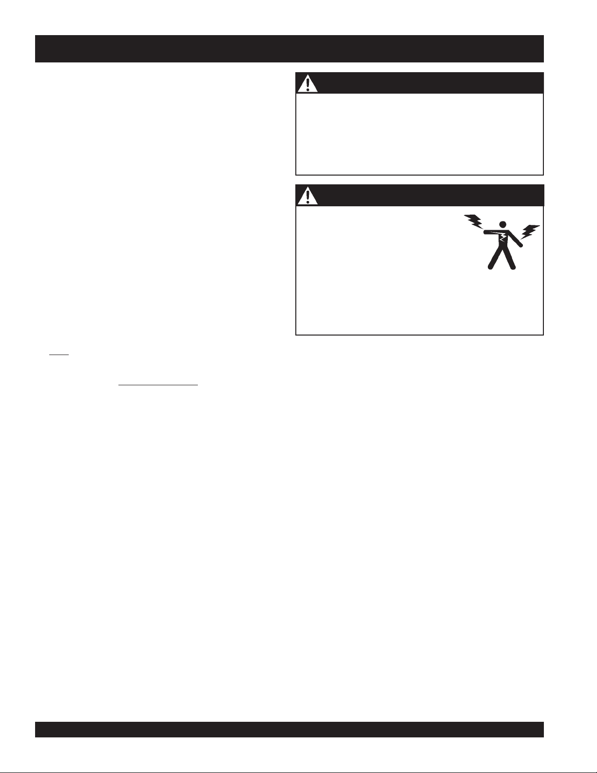
GLOBUG 4-SPOT
You WILL be
NOT follow directions.
WARNING
You CAN be
NOT follow directions.
CAUTION
You CAN be
KILLED
KILLED
INJURED
PAGE 6 — GLOBUG 4-SPOT — OPERATION AND PARTS MANUAL — REV. #3 (12/15/08)
or
SERIOUSLY
or
SERIOUSLY
if you DO NOT follow directions.
injured if you DO
injured if you DO
WARNING - Burn Hazards
Engine components can generate extreme
heat. To prevent burns, DO NOT touch
these areas while the engine is running or
immediately after operations. Never
operate the engine with heat shields or heat
guards removed.
CAUTION - Respiratory Hazard
ALWAYS wear approved
protection when required.
respiratory
Page 7
GLOBUG 4-SPOT — SAFETY MESSAGE ALERT SYMBOLS
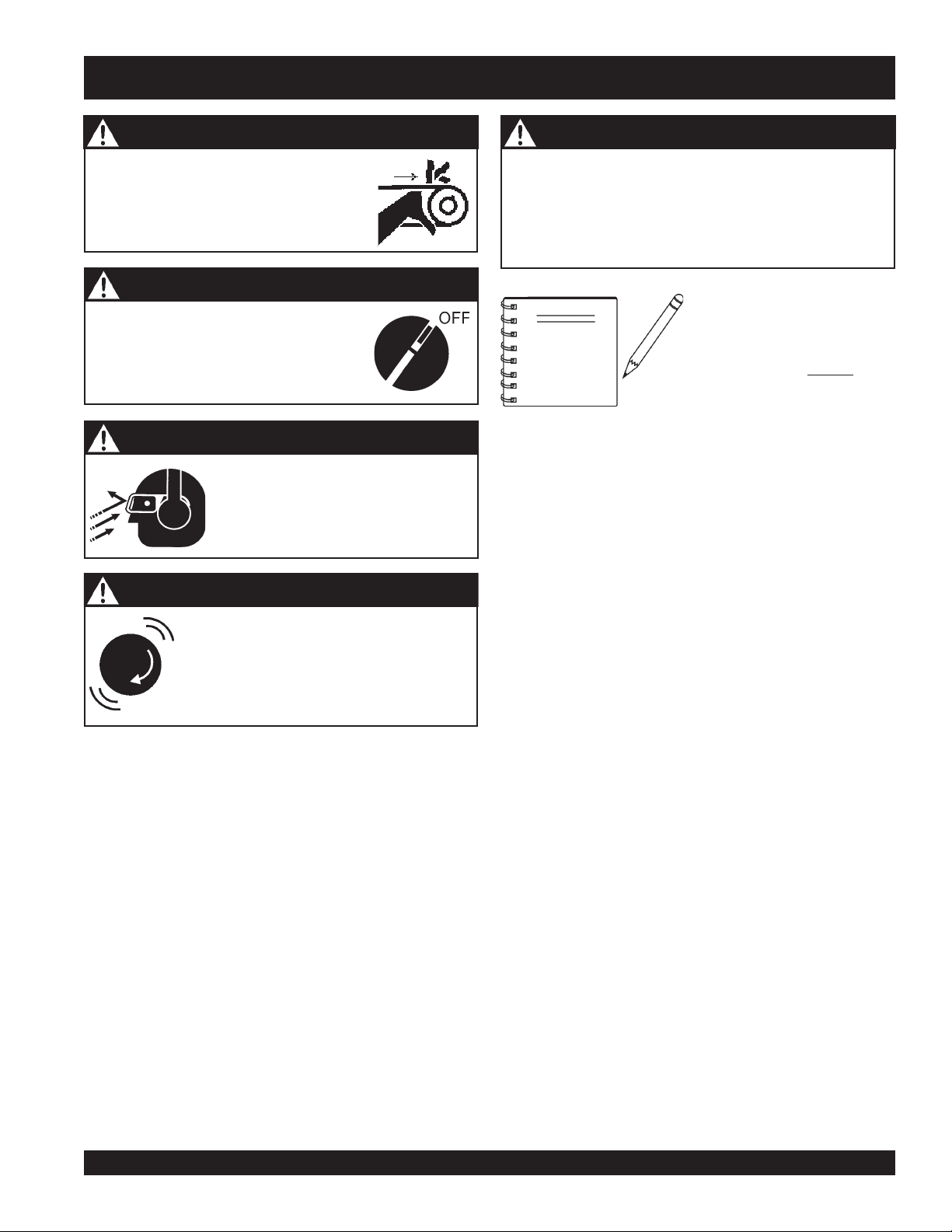
CAUTION - Rotating Parts
NEVER operate equipment with covers,
or guards removed. Keep fingers, hands,
hair and clothing away from all moving
parts to prevent injury.
CAUTION - Accidental Starting
ALWAYS place the power source, circuit
breakers or ON/OFF switch in the OFF
position, when the generator is not in use,
unless connected to transfer switch.
CAUTION - Sight and Hearing Hazards
ALWAYS wear approved eye and
hearing protection.
CAUTION - Equipment Damage Messages
Other important messages are provided throughout this
manual to help prevent damage to your lighting system,
other property, or the surrounding environment.
This lighting system, other
NOTE
property, or the surrounding
environment could be
damaged if you
instructions.
do not
follow
CAUTION - Over-Speed Conditions
NEVER tamper with the factory settings of
the engine governor settings. Personal injury
and damage to the engine or equipment can
result if operating speed ranges above
maximum allowable.
GLOBUG 4-SPOT — OPERATION AND PARTS MANUAL — REV. #3 (12/15/08) — PAGE 7
Page 8
GLOBUG 4-SPOT — RULES FOR SAFE OPERATION
WARNING - READ THIS MANUAL
Failure to follow instructions in this manual may lead to
Serious Injury
operated by trained and qualified personnel only! This
equipment is for industrial use only.
or even
Death
. This equipment is to be
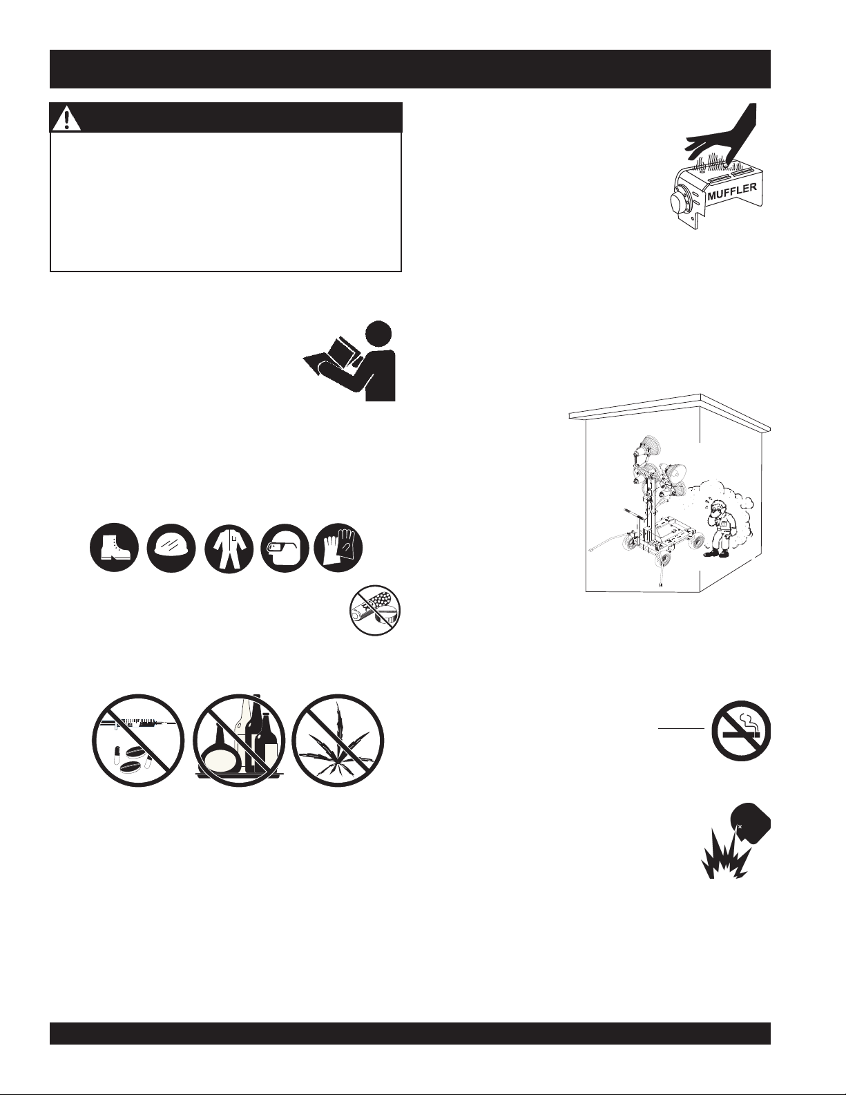
■
NEVER touch the hot exhaust manifold,
muffler or cylinder. Allow these parts to
cool before servicing engine or mixer.
The following safety guidelines should always be used
when operating the GLOBUG 4-SPOT.
The following safety guidelines should always be used when
operating the GLOBUG 4-SPOT:
GENERAL SAFETY
■
DO NOT operate or service this
equipment before reading this entire
manual.
■
This equipment should not be operated by persons under
18 years of age.
■
NEVER operate this equipment without proper protective
clothing, shatterproof glasses, steel-toed boots and other
protective devices required by the job.
■
NEVER operate this equipment when not feeling
■
High Temperatures – Allow the engine to cool before
adding fuel or performing service and maintenance
functions. Contact with
burns.
■
The engine of this lighting system/generator requires an
adequate free flow of cooling air. NEVER operate the
generator in any enclosed or narrow area where free flow of
the air is restricted. If
the air flow is restricted
it will cause serious
damage to the
generator engine and
may cause injury to
people. Remember the
engine of the lighting
system/generator
gives off DEADLY
carbon monoxide gas.
well due to fatigue, illness or taking medicine.
hot!
components can cause serious
■
NEVER operate this equipment under the influence of
drugs
■
Whenever necessary, replace nameplate, operation and
or
alcohol
.
safety decals when they become difficult read.
■
Manufacturer does not assume responsibility for any
■
■
■
accident due to equipment modifications.
■
NEVER use accessories or attachments, which are not
■
recommended by Multiquip for this equipment. Damage
to the equipment and/or injury to user may result.
PAGE 8 — GLOBUG 4-SPOT — OPERATION AND PARTS MANUAL — REV. #3 (12/15/08)
ALWAYS refuel in a well-ventilated area, away from sparks
and open flames.
ALWAYS use extreme caution when working with
flammable liquids. When refueling, stop the
engine and allow it to cool. DO NOT
around or near the machine. Fire or explosion
could result from fuel vapors, or if fuel is spilled
on a hot engine.
NEVER operate the GloBug in an explosive
atmosphere or near combustible materials. An
explosion or fire could result causing severe
bodily harm or even death.
Topping-off to filler port is dangerous, as it tends to spill fuel.
Wipe up any spilled fuel immediately.
smoke
Page 9
GLOBUG 4-SPOT — RULES FOR SAFE OPERATION
■
ALWAYS make sure that the GloBug is secure on firm level
ground so that it cannot slide or shift around, endangering
workers. Also keep the immediate area free of bystanders.
■
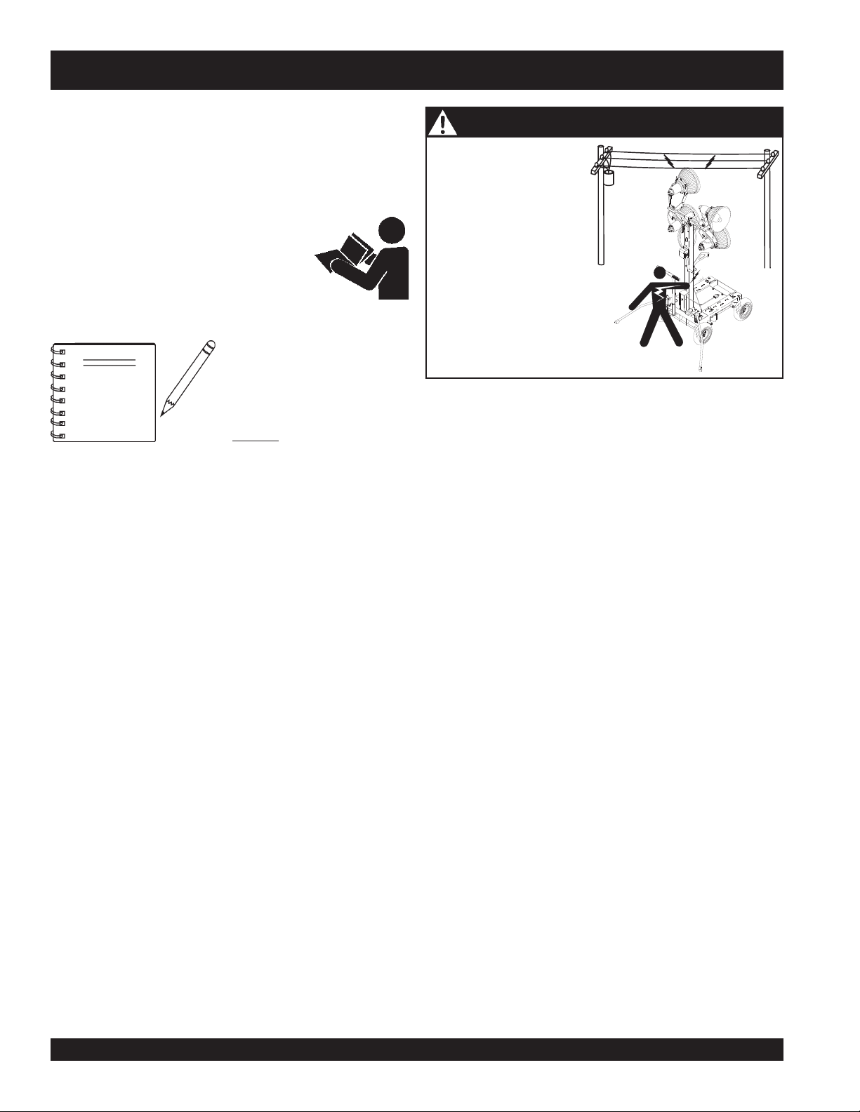
ALWAYS keep area behind GloBug clear of people while
raising and lowering mast.
■
To prevent the GloBug from overturning, NEVER use in winds
that exceed 22 mph(10m/s).
■
To prevent the GloBug from rolling, ALWAYS place the
GloBug on a firm flat surface. Surface slant should not exceed
5 degrees.
■
To prevent the GloBug from rolling, ALWAYS apply the
parking brake. For additional safety place chock blocks
behind the wheels.
■
The GloBug must use a generator that is at least 220
lbs. (100 kg) minimum. This will prevent the GloBug from
tipping over.
■
The GloBug should only be used in temperatures between
23-104 degrees Fahrenheit (-5 to 40 degrees Celsius).
Failure to comply with these operating parameters could
cause the lamp to malfunction and shorten the ballast
life.
■
NEVER use the GloBug in
rain, snow
or areas of high
humidity that could generate electrical storms.
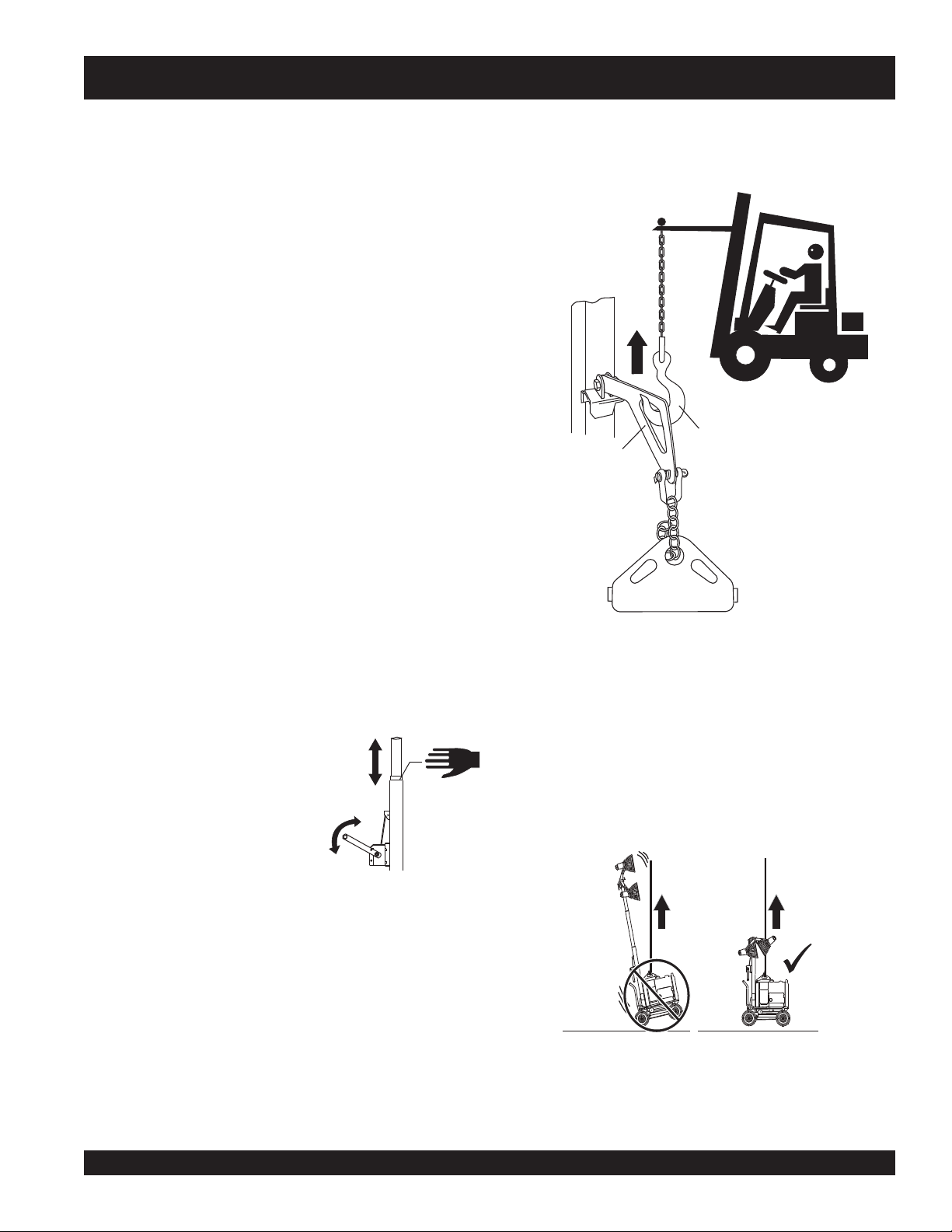
LIFTING/TRANSPORTING THE GLOBUG
■
ALWAYS use the lifting hanger, when lifting of the GloBug
is required.
LIFTING
HOOK
LIFTING
HANGER
GENERATOR
LIFTING BALE
LIFTING
SCHACKLE
■
Set the GloBug's tire air pressure to 35.5 psi (245kPa).
Check daily. Low tire pressure could adversely affect the
parking brake.
MAST SAFETY
■
When raising or lowering the mast,
keep hands and fingers clear of
the various mast sections, this will
PINCH
POINT
prevent hands and fingers from
getting pinched.
■
When raising the mast and to prevent tipping, ALWAYS
deploy outriggers
.
■CHECK the mast and winch cables for wear. If any problem
occurs when lower or raising the mast STOP immediately!
Contact a trained MQ technician for assistance.
■
NEVER pivot or retract mast while unit is operating.
■
NEVER use the lighting system mast as a crane. DO
NOT lift anything with the mast.
■
NEVER attach anything to the lighting system mast.
■
Use a crane, forklift or suitable lifting device of adequate
lifting capability when the lifting of the GloBug is required.
■
Make sure the mast is completely lowered before lifting
the GloBug.
■
When the GloBug is lifted from its correct lifting point, it
should lift straight up (not tilted). DO NOT attempt to lift
the GloBug if its position is tilted while lifting.
INCORRECT
CORRECT
■
ALWAYS lower the tower when not in use, or if high winds
or electrical storms are expected in the area.
GLOBUG 4-SPOT — OPERATION AND PARTS MANUAL — REV. #3 (12/15/08) — PAGE 9
Page 10
GLOBUG 4-SPOT — RULES FOR SAFE OPERATION
■
When transporting the GloBug 4-Spot, lower the mast
.
Tighten the lamp adjustment lever and make sure
fully
that the lighting unit assembly is fixed to the mast before
transporting. This will prevent the light assembly from
falling down or being damaged during transport.
LAMP SAFETY AND CARE
■
NEVER leave any grease or oil residue on lamp surface
when replacing or removing lamp. This can create hot
spots, reducing the service life of the lamp.
■
ALWAYS make sure the lamp surface is clean and dry.
■
ALWAYS replace with MQ recommended type lamp. See
parts section of this manual.
■
NEVER use force when installing a lamp. Excessive force
could cause the lamp to break causing bodily harm.
■
NEVER attempt to replace lamp with the power on. Always
unplug the power cord from the generator when changing
the lamp.
■
ALWAYS allow a sufficient amount of time for the lamp to
cool
before changing. The possibility exists of severe
burns.
DANGER - GloBug High Danger Areas
The
DANGER
considered
to. Failing to understand these areas could result in
Harm, Electrical
Please pay close attention when operating the lighting
system.
items listed below and on the next page are
High DANGER
Shock, Electrocution
areas and should be adhered
Bodily
, and even
Death!
DANGER - Grounding the GloBug for Operation
The GLOBUG 4-SPOT is equipped
with a
ground terminal
protection. ALWAYS complete the
grounding path
system to an external grounding source.
ALWAYS make certain the GloBug is well grounded and
securely fastened to a good earth ground (ground rod). The
possibility exists of
even Death
if the GloBug is not grounded.
for your
from the lighting
Electrical Shock, Electrocution, and
■
ALWAYS have a
trained technician
to install and remove
lamp, or replace any damaged fixture wiring.
PAGE 10 — GLOBUG 4-SPOT — OPERATION AND PARTS MANUAL — REV. #3 (12/15/08)
Page 11

GLOBUG 4-SPOT — RULES FOR SAFE OPERATION
DANGER - GloBug Electric Shock Hazards
ALWAYS keep electrical cords in good condition. Worn,
bare or frayed wiring can cause electrical
shock, thus causing
even Death
.
Bodily Harm or
WET
HANDS
NEVER grab or touch a live power
cord with wet hands, the possibility
exists of
Electrical Shock,
Electrocution, and even Death!
POWER
CORD
(POWER ON)
DANGER - GloBug Electric Shock Hazards
NEVER operate the
GloBug or handle any
electrical equipment
while standing in water,
while bare foot, while
hands are wet, or in the
rain. A dangerous
electrical shock
occur causing
could
Severe
Bodily Harm or even
Death.
Maintenance Safety
■
NEVER lubricate components or attempt service on a running
GloBug.
■
ALWAYS allow the GloBug a proper amount of time to cool
before servicing.
■
Keep the GloBug in proper running condition.
■
Fix damage to the GloBug immediately and always replace
broken parts.
■
ALWAYS use the required tool for the job application.
Using damaged or worn tools or using tools inappropriate
for the required application is very dangerous, and may
cause damage to
the machine and
service personnel.
Make sure to use
the appropriate tool
for the specific job.
Emergencies
■
ALWAYS know the location of the
nearest
fire extinguisher
.
DANGER - GloBug Overhead Obstructions
ALWAYS make sure the
area above GloBug is
open and clear of
overhead power lines
and other obstructions.
The tower extends in
excess of 16.5 ft. (5
meters). Contact with
overhead powerlines or
other obstructions could
result in equipment
damage,
Serious Injury or Death
!
■
ALWAYS know the location of the nearest
first aid kit
■
In emergencies
or
keep a phone on the job site
numbers of the nearest
department
.
always
know the location of the nearest phone
. Also know the phone
ambulance, doctor
. This information will be invaluable in the case
of an emergency.
and
fire
GLOBUG 4-SPOT — OPERATION AND PARTS MANUAL — REV. #3 (12/15/08) — PAGE 11
Page 12

GLOBUG 4-SPOT — SPECIFICATIONS
topS-4guBolG
ledoMCS34BG
egatloVtupnICAV021
ycneuqerFesahP-elgniSzH06
tnerruC.xaMspmA81
snoitacificepS.1elbaT
dniW)hpk64.08(hpm56
)rotarenegssel(thgieW)gk561(.sbl463
pmaL
epyTpmaLedilaHlateMttaW004)4(
snemuL000,631
tsaM
egatSforebmuN3
s
thgieHmumixaM)sretem2.4(.tf8.31
rotareneG
rotareneGhtiwytilibatS
launaMrotareneGdeificepSeeS
PAGE 12 — GLOBUG 4-SPOT — OPERATION AND PARTS MANUAL — REV. #3 (12/15/08)
Page 13
C
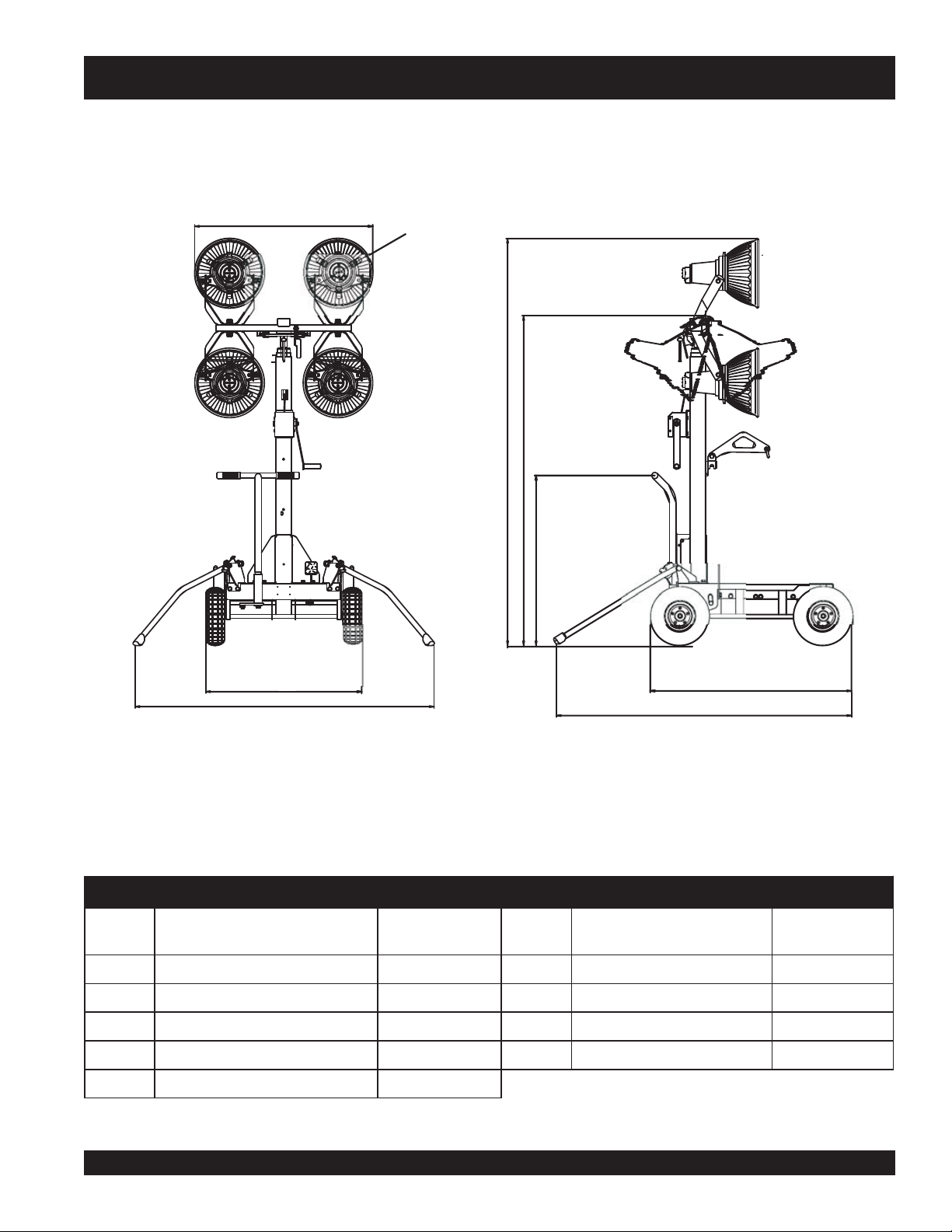
GLOBUG 4-SPOT — DIMENSIONS
D
E
F
G
A
B
Figure 2. Dimensions
SNOISNEMID.2ELBAT
ecnerefeR
retteL
AesaBleehW).mm008
B)deyolpeDsreggirtuO(htdiW).mm006,1(.tf52.5G )eldnaHgnire
noitpircseD
.tfnoisnemiD
).mm(
(.tf26.2F )noitisoPdewotStsaM(thgieH).mm007,1(.tf85.5
ecnerefeR
retteL
etS(thgieH).mm878(.tf88.2
H
I
noitpircseD
.tfnoisnemiD
).mm(
C)stinUgnithgiL(htdiW).mm029(.tf20.3H )leehWraeRottnorF(thgneL).mm040,1(.tf14.3
D)tin
E)noitisoPdeyolpeDtsaM(thg
ieH.xaM).mm0024(.tf87.31
GLOBUG 4-SPOT — OPERATION AND PARTS MANUAL — REV. #3 (12/15/08) — PAGE 13
UgnithgiL(retemaiD).mm063(.tf81.1I )reggirtuOotleehWtnorF(htgneL).mm055,1(.tf90.5
Page 14
GLOBUG 4-SPOT — GENERAL INFORMATION
The Multiquip GLOBUG 4-SPOT is a general purpose
floodlight tower intended for emergency and remote lighting
conditions. The GloBug can be powered by a variety of
Multiquip's series generators. Power requirements for running
the GloBug are 120 VAC, 60 Hz @ 18 amps.
Please read carefully the specified
generator manual that will accompany your
GLOBUG 4-SPOT. This manual will explain
how to operate and maintain the generator.
All information related to the
generator will be referenced in a
NOTE
separate (supplied) "Operation
and Parts Manual". Operation
and maintenance of the generator
will not
manual.
be referenced in this
DANGER - GloBug Overhead Obstructions
ALWAYS make sure the
area above GloBug is
open and clear of
overhead power lines
and other obstructions.
The tower extends in
excess of 14 ft. (4.3
meters). Contact with
overhead powerlines or
other obstructions could
result in equipment
damage,
The lighting system of Multiquip's GLOBUG 4-SPOT is
comprised of four "Metal Halide" 400 watt lamp with an output
of 136,000 lumens.
Serious Injury or Death
!
The GloBug 4-Spot has the following features:
Stainless steel mast which prevents rust.
Mast stopper prevents sudden drop of mast.
Steering wheel for easy cart movement.
Large-sized pneumatic tires for easy travel even in
rough and uneven roads.
Secure lock-type foot brake.
Tire bumper for protection.
Easy to disassemble and service parts.
Safety winch prevents reverse winding.
PAGE 14 — GLOBUG 4-SPOT — OPERATION AND PARTS MANUAL — REV. #3 (12/15/08)
Page 15

NOTE PAGE
GLOBUG 4-SPOT — OPERATION AND PARTS MANUAL — REV. #3 (12/15/08) — PAGE 15
Page 16
GLOBUG 4-SPOT — COMPONENTS
1
2
12
3
5
7
9
11
10
13
8
4
6
14
15
17
20
19
21
16
18
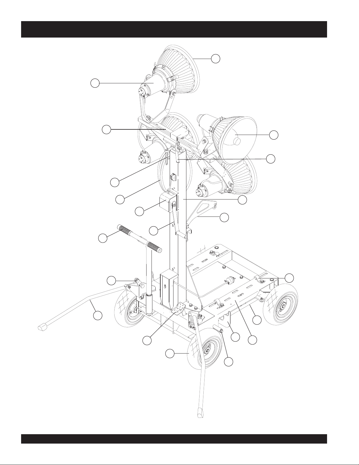
Figure 6. Major Components
PAGE 16 — GLOBUG 4-SPOT — OPERATION AND PARTS MANUAL — REV. #3 (12/15/08)
Page 17

GLOBUG 4-SPOT — COMPONENTS
Figure 6 shows the location of the controls and components
for the GLOBUG 4-SPOT. The functions of each control is
described below:
1. Reflex Mirror – Enhances lighting from the bulbs.
2. Lighting Unit – Consists of 4 lamps in their sockets.
3. Lamp Stand – holds the four lamps of the lighting unit
together.
4 Lamp – 400 watt metal-halide type lamp. Replace with
only MQ recommended type lamp. Always allow a
sufficient amount of time for the lamp to
before changing.
5. Adjust Lever – This lever allows the lamp to be
positioned up or down. Turn counterclockwise to release
lamp and position. Turn clockwise to tighten.
6. Fold Lever – Holds the lamp stand in place after
adjusting its height.
7. Lamp Power Cable – Connects the lamps to the power
(generator).
8. Mast – This mast is comprised of three separate stages.
The mast can be raised in excess of 13.78 feet. (4.2
meters). Again when raising the mast, always be on the
lookout for overhead obstructions.
cool down
14. Locking Clamps – To secure the generator to the
GloBug cart platform, place clamps (4) around the pipe
frame of the generator. Tighten securely to prevent
movement.
15. Outriggers – ALWAYS deploy the outriggers when
raising the mast.
16. Guide Square Pipe - frames the generator.
17. Brake Pedal – Step on this pedal to apply the brakes. To
release the brakes, press down on brake pedal again.
18. Cart – Holds the generator that supplies power to the
lighting unit.
19. Tires – The GloBug 4-Spot uses 4 pneumatic type tires.
Replace with only recommended type tire . NEVER allow
the rear tires to go flat. This could adversely affect the
braking system. Inflate tires to 35.5 psi (245kPa).
20. Catcher – Holds the outrigger in place in the stow
position.
21. Brake Pad – When the brake pedal is pressed, this pad
will strike and hold the rear tires in place. Make sure rear
tires are inflated to the correct air pressure.
9. Mast Winch – Use this winch to raise and lower the mast.
Always be on the lookout for overhead obstructions.
Keep immediate area free of bystanders and debris when
raising the mast.
10. Winch Handle– Use this handle to adjust the mast
height.
11. Lift Hanger – When lifting of theGloBug is required
always use a suitable lifting device of adequate lifting
capability. NEVER stand underneath the GloBug while it
is being lifted.
12. Steering Handle – The GloBug can be moved in either
a forward or reverse direction by pulling back or pushing
forward on the T-handle. In addition the front wheels are
designed to turn in the opposite direction of the T-handle
placement thus allowing the GloBug to turn either left or
right.
13. Counterweight Lever – Holds the outriggers in place
when deployed.
GLOBUG 4-SPOT — OPERATION AND PARTS MANUAL — REV. #3 (12/15/08) — PAGE 17
Page 18

GLOBUG 4-SPOT — SETUP
AC
CIRCUIT
BREAKER
120/240V
30A
V
OFF
21A
SOCKET
LAMP
CAUTION - Read Manual
backwards and place it in the deployed position, as shown
in Figure 9. The outriggers will automatically lock in place
3. Lift up on each outrigger (2) from its stow position, rotate
Please read this entire manual carefully
once they touch the ground,
before attempting to operate the GloBug.
Failure to read this manual could cause
damage to the GloBug and serious injury
to the operator.
GloBug Setup
1. Using the T-handle (Figure 7) place the GloBug on a
firm level surface
so that it will not slide or turn over.
STOW
POSITION
ON
0N
FF
O
F
OF
E
L
L
N
D
O
O
I
I
R
T
A
T
H
R
N
C
E
T
P
I
O
O
W
C
S
V
0
2
A
1
0
0
2
2
1
V
0
4
2
/
R
V
E
0
W
2
O
P
1
H
L
C
L
T
I
F
U
W
F
F
S
O
A
0
2
V
0
A
2
1
1
2
T
I
A
U
0
C
3
R
I
R
E
C
K
C
A
A
E
R
B
V
0
4
2
/
A
0
0
2
3
1
6000
H
-6
A
G
OUTRIGGERS
DEPLOYED
Figure 9. Outriggers (Deployed Position)
Figure 7. T-Handle (Directional Control)
2. To apply the parking brake (Figure 8), step on the brake
pedal and pull back on the T-handle. This will lock the
rear wheels. For additional safety use chock blocks to
prevent rolling.
STEP DOWN
ON BRAKE PEDAL
Lamp Assembly
1. Screw the lamp into the socket (use 400 watt metalhalide type lamp). Always allow a sufficient amount of
time for the lamp to cool down before changing. See
Figure 10.
Figure 10. Installing the Lamp
PARKING
BRAKE SET
Figure 8. Parking Brake (Set Position)
PAGE 18 — GLOBUG 4-SPOT — OPERATION AND PARTS MANUAL — REV. #3 (12/15/08)
Page 19

GLOBUG 4-SPOT — SETUP
2. Adjust the reflex mirror and the socket together so that
the cables of the two upper light ing units are positioned
downward sand the cables of the two lower lighting units
Raising the Lamp Stand
1. Support the lighting units with one hand and pull up the
fold lever with the other hand. The lever wil spring up.
are positioned upwards. See Figure 11.
SOCKET
CABLE
REFLEX
MIRROR
Figure 11. Positioning the Socket
2. Push up the lighting unit and push down the fold lever
to lock the lamp stand (Figure 14).
3. Tighten all three latches to secure reflex mirror to the
socket. See Figure 12.
FOLD LEVER
Figure 13. Raising Lamp Stand
LATCH
FOLD LEVER
Figure 12. Securing Latch
Figure 14. Locking Lamp Stand
CAUTION - FOLD LEVER PINCH POINT
When operating the fold lever, keep hands and fingers
clear of the pinch points to prevent injury.
GLOBUG 4-SPOT — OPERATION AND PARTS MANUAL — REV. #3 (12/15/08) — PAGE 19
Page 20

GLOBUG 4-SPOT — SETUP
Turning All Lights In One Direction
1. Loosen the adjust lever. Turn the lighting units in the
desired direction (Figure 15).
CAUTION - MAST PINCH POINT
When raising or lowering the mast, keep hands and fingers
clear of the various mast sections, this will prevent hands
and fingers from getting pinched.
ADJUST LEVER
Adjusting Height of the Lights
Figure 15. Adjusting Direction of Lighting Units
1. Turn the handle of the mast winch clockwise to raise
the lighting unit and turn the handle of the mast winch
Turning Lights Individually
counterclockwise to lower the lighting unit (Figure 18).
1. Hold the arm of the lamp and turn it to the desired
direction (Figure 16.
ARM
Figure 16. Adjusting Direction of Individual Lamp
Adjusting Angle of the Lights
1. Hold the socket of the lamp and tilt it to the desired
direction (Figure 17).
SOCKET
DANGER - HIGH VOLTAGE POWER LINES
When raising mast, ALWAYS be on
the lookout for overhead obstructions
such as high voltage power lines. The
possibility exists of electrocution,
even death! if the GloBug comes in
Figure 17. Adjusting Angle of Light
PAGE 20 — GLOBUG 4-SPOT — OPERATION AND PARTS MANUAL — REV. #3 (12/15/08)
contact with
UP
DOWN
WINCH
HANDLE
Figure 18. Adjusting Height of Light
high voltage power lines
.
Page 21

GLOBUG 4-SPOT — OPERATION
DANGER - HIGH VOLTAGE POWER LINES
When raising mast, ALWAYS be on
the lookout for overhead obstructions
such as high voltage power lines. The
possibility exists of electrocution,
even death, if the GloBug comes in
contact with
high voltage power lines
.
Section" of the supplied generator manual.
4. Leave the engine idling for about 3 minutes to warm it
up.
5. Place the generator lamp switch (Figure 19) to the ON
position.
6. The lamp should light up and give a fully bright light in
3. Start the generator as referenced in the "Start-up
Applying Power
about 5 minutes. If the lamp is not on, check all
connections and repeat steps 1 through 5. If the lamp
1. Make sure the generator lamp switch (Figure 19) is in
the OFF position.
still does not come on contact the MQ service
department.
Shutdown
STARTER KEY
1. Place the generator lamp switch (Figure 19) to the OFF
position.
GENERATOR
LAMP SWITCH
2. Disconnect the GloBug 4-Spot AC power cable from the
generator.
3. Shutdown generator as referenced in the "Shutdown
Section" of the supplied generator manual.
Figure 19. GeneratorLamp Switch
CAUTION - READ GENERATOR MANUAL
Before attempting to operate the
generator, READ the entire operation
section of the manual. Failure to read
manual could cause severe damage to
the equipment and bodily harm to the
operator.
2. The GloBug has a power requirement of 120 VAC, 60 Hz
@ 18 amps. Connect the GloBug 4-Spot AC power cord
to the 120 VAC twist-lock receptacle (Figure 20) on the
the supplied generator.
120 VAC
TWIST-LOCK
RECEPTACLE
GLOBUG 4-SPOT
POWER CABLE
20A
120V
TYPICAL
GENERATOR
FRONT PANEL
CAUTION - LAMP COOL DOWN
Allow a sufficient amount of time (15-20 minutes) for the
lamp to
cool down
before turning on lighting unit again.
Do not touch lamp before cooling down. Lamp surface is
very hot and can cause burns (Figure 21).
CAUTION - GENERATOR DAMAGE
DON NOT shut down generator engine with the lamp
switch on. This could cause damage or break the
generator.
Figure 21. Hot Lamp Surface
Figure 20. 120 VAC Receptacle
GLOBUG 4-SPOT — OPERATION AND PARTS MANUAL — REV. #3 (12/15/08) — PAGE 21
Page 22

GLOBUG 4-SPOT — STORAGE
PUSH DOWN
LIGHTING UNIT
Preparation of Lighting Unit For Storage
1. Using the mast winch (Figure 18),
lower the mast fully
.
Turn winch handle counterclockwise to lower mast.
2. Set the lighting units facing the front (Figure 22).
LIGHTING UNIT
FACING FRONT
Figure 22. Lighting Unit Facing Front
4. Push down the lighting unit (Figure 24). Some force is
required when pushing down because of the installed
springs.
Figure 23. Pushing Down Lighting Unit
5. After lighting unit has been completely pushed down,
push down fold lever (Figure 24) to lock the lamp stand
in place.
3. Holding the lighting unit with one hand, pull up the fold
lever with the other hand (Figure 23).
FOLD LEVER
Figure 23. Fold Lever
PUSH DOWN
LOCK LEVER
Figure 24. Locking Lamp Stand
PAGE 22 — GLOBUG 4-SPOT — OPERATION AND PARTS MANUAL — REV. #3 (12/15/08)
Page 23

GLOBUG 4-SPOT — STORAGE
7. To unlock outriggers, push downward on the counter-
weight lever indicated by arrow (Figure 25). Grab hold of
outrigger, pull upward, push down and place in stow
position (Figure 26..
Figure 25. Outriggers (Released)
Storage
1. Wipe dirt or foreign matter that may have accumulated
on the GloBug 4-Spot during operation. Use a mild
detergent to clean the unit. DO NOT spray the engine
with water.
2. Avoid storing the GloBug 4-Spot in areas that can be
exposed to rain, harsh elements, and high humidity.
3. Place the GloBug 4-Spot in a clean dry location away
from dirt and debris.
CAUTION - READ SAFETY GUIDELINES
Before performing any maintenance
procedures, be sure to READ the lamp,
balloon, and general safety guidelines in
this manual. Failure to
understand
could cause severe equipment damage
and bodily harm.
these safety guidelines
read
and
Figure 26. Outriggers (Stow Position)
8. Press down on the top of the brake pedal (Figure 22)
and hold, then release. This action will dis-engage the
brake mechanism and allow the GloBug to be moved.
Figure 22. Parking Brake (Release Position)
GLOBUG 4-SPOT — OPERATION AND PARTS MANUAL — REV. #3 (12/15/08) — PAGE 23
Page 24

LIGHTING UNIT 1
LIGHTING UNIT 3
9
LIGHTING UNIT 2
17
16
LIGHTING UNIT 4
BALLAST
GLOBUG 4-SPOT — MAINTENANCE (WIRING DIAGRAM)
15
BALLAST
RED
1
CAPACIT R
AC120V
YEL
YEL/BLK
YEL
13
14
2
WHT
BLK
BLK
WHT
11
10
6
BLK
4
2
RED
GRAY
BRUE
WHT
BROWN
ORANGE
YEL
BLK
ORANGE
WHT
RED
BRUE
GRAY
BROWN
BLK
YEL
3
8
LIGHTING UNIT
WHT
5
7
YEL
2
YEL
YEL/BLK
12
BALLAST
①
RED
O
RED
RED
CAPACITOR
④
YEL/BLK
YEL/BLK
YEL
RED
CAPACIT R
BALLAST
RED
YEL
YEL
YEL
RED
BALLAST
CAPACITOR
RED
③
O
11
10
BROWN
BROWN
GRAY
GRAY
RED
RED
ORANGE
ORANGE
BLK
WHT
WHT
BLK
BUEL
BUEL
YEL
YEL
②
1311001002 LIGHTING UN AY
17
16
15
E000069800
14
1367020430 TERMINAL R2-4
13
E000034400 TERMINAL TMEV2-4S
12
E000047600 TERMINAL TMEV1.25-3S
E000044800
11
E000044900
10
1407021030
9
1407020930
8
E000031600 TERMINAL
7
A400082000
6
5
A400081900
A300069900
4
3
A300069501
2
A300069601
1
A300069700
REF.
DESC
BALLAST A (400 W)
RECEPTACLE HOUSING 2
RECEPTACLE HOUSING 12
PLUG HOUSING 12
CABLE (JUMPER-BLACK) CP
CABLE (JUMPER-WHITE) CP
CABLE (JOINT-43SC-USA) CP
CABLE (LAMP-43SC-USA) CP
CABLE (BALLAST-43SC-USA) CP
CABLE (LAMP-43SC-USA) CP
LAMPE000031700
PLUG HOUSING 2
DESCRIPTIONPART NUMBER
PAGE 24 — GLOBUG 4-SPOT — OPERATION AND PARTS MANUAL — REV. #3 (12/15/08)
Page 25

NOTE PAGE
GLOBUG 4-SPOT — OPERATION AND PARTS MANUAL — REV. #3 (12/15/08) — PAGE 25
Page 26

L1
M3
M4
L3
E1
M2
L5
L2
M5
M6
GLOBUG 4-SPOT — MAINTENANCE
L4
M1
L6
L7
L8
C6
C1
C7
C9
C2
C3
C4
PAGE 26 — GLOBUG 4-SPOT — OPERATION AND PARTS MANUAL — REV. #3 (12/15/08)
C5
C10
C8
Page 27

GLOBUG 4-SPOT — MAINTENANCE
For a prolonged life cycle an extended quality follow the
recommended GloBug 4-Spot service guidelines as
referenced in Table 3.
ERUGIFTRAPMETIKCEHCNOITULOS
ECNANETNIAMDNAKCEHCCIDOIREP.3ELBAT
1LesaBpmaL?esoolesabpmaL.ylerucesniwercS
2LtcatnoCniP?detcennocsidroesooltcatnocniP .ylerucestcennocronethgiT
3LtuN?thgitoottonroesooloottontuN.yltcerrocnethgiT
4LdnatSpmaLrofegniH?ylhtoomsevomtonseodegniH.esaergylppA
pmaL
5LdnatSpmaLroftoviP?ylhtoomsnruttonseodtoviP.esaergylppA
6LpmaL?nekorbrodenrubpmaL.ecalpeR
7LssalGtnorF?ytridssalgtnorF.tridffoepiW
8LrorriMxelfeR?nekorbroytridrorrimxelfeR .ecalperrotridffoepiW
1MreveLdloF?ylreporpkcolnudnakcolseodreveldloF.riapeR
2MecafruSgnidilStsaM?ylhtoomsedilstonseodecafrusgnidilstsaM.esaergylppA
3MepoReriW?degamaD .ecalperroesaergylppA
tsaM
4MdnEepoReriW?)gnikluac(degamaddneeriwsI.ecalpeR
5MhcniW?ekarbhcniwevitcefeD.ecalperroriapeR
6MpotSytefaS?evitcefedhctalytefaS.ecalperroriapeR
1CthgieW-retnuoC?ylhtoomslevomtonseoD.esaergyarpS
❖
■
❖
●
●
❖
❖
❖
●
❖
❖
❖
❖
▲
●
2CsreggirtuO?ylhtoomsevomtonseoD.esaergyarpS
3CsleehWdnaeldnah-T?sknilesooL.ylerucesnethgiT
4CeldnaHroftloB?tlobesooL.ylerucesnethgiT
5CladePekarB?ylhtoomsgnikrowtonegakniLesaergyarps,kcehC
traC
cirtcelE
5CladePekarB?tuo-nrowhctoN.ecalpeR
6CregnaH?noitallatsniesooL.ylerucesnetsaF
7CtoviPleehWtnorF?ylhtoomsnruttonseoD.esaergylppa,kcehC
8CseriT?)aPk492(isp5.53tonerusserperiT.tsujdA
9CtfahStnorFrofkniL?ylhtoomsevomtpnseodegakniL.esaergyarpS
01CekarB?ylreporpkrowtonseoD.tsujdA
1EelbaCrewoP?elbacnrowroevitcefeD.ecalpeR
2EegatloVdaol-noN?CAV521tontuptuorotarenegsI .rotarenegecalperrotsujdA
kcehCyliaD-
❖
■
sruoH02yrevE-
●
sruoh001yrevE-
▲
sruoh005yrevE-
●
■
■
❖
❖
■
●
❖
●
❖
❖
●
GLOBUG 4-SPOT — OPERATION AND PARTS MANUAL — REV. #3 (12/15/08) — PAGE 27
Page 28

GLOBUG 4-SPOT — TROUBLESHOOTING (LAMPS)
Practically all breakdowns can be prevented by proper
handling and maintenance inspections, but in the event of a
breakdown, please take a remedial action following the
diagnosis based on the Lamp Troubleshooting (Table 4)
information shown below.
MOTPMYSMELBORPELBISSOPNOITULOS
?esoolpmalsI .tekcosotniylerucespmalwercS
.thgiltonseodpmaL
?ecruos
sI
?)CAV021-egatlov
If the problem cannot be remedied, please leave the unit
just as it is and consult or company's service department.
?detcennocylerucestonsrelpuocerA.yltcerrocrelpuoctcennoC
?ffodenruthctiwspmalrotarenegsI.hctiwsnonruT
?detcennocylreporptonsrotcennocerA .rotcatnocdetcennocsidtcennoC
rehto(secnailppacirtcelerehtoynaerA
rewopotnideggulp)rewotthgilnaht
daol-non(lamrontonegatlovrotareneg
GNITOOHSELBUORTPMAL.4ELBAT
.secnailpparehtollagulpnU
.rotarenegecalperroriapeR
?elbitapmoctonpmalfoledomsI.pmalQMeniunegesU
?niagathgilothguonelooctonpmalsI
deriuqersisetunim03ot02folavretnI(
)niagapmalnogninruterofeb
daol-non(lamrontonegatlovrotarenegsI
arofsthgilylnopmaL
.emittrohs
?)V021-egatlov
nahterom(hgihooterutarepmettneibmasI
?)C°04(F°401
.noitalitnev
.nwodloocotpmalroftiaW
.rotarenegecalperroriapeR
reporpsierehterehwpmalevoM
PAGE 28 — GLOBUG 4-SPOT — OPERATION AND PARTS MANUAL — REV. #3 (12/15/08)
Page 29

GLOBUG 4-SPOT — TROUBLESHOOTING (MAST)
Practically all breakdowns can be prevented by proper
handling and maintenance inspections, but in the event of a
breakdown, please take a remedial action following the
diagnosis based on the Mast Troubleshooting (Table 5)
information shown below.
MOTPMYSMELBORPELBISSOPNOITULOS
?tsamnithguacelbacsI.eerfelbacteS
ebtonnactsaM
.desiar
gnimocspeektsaM
.nwod
?hcniw
?noitcerid
?evitcefedhctalhcniwsI .ylreporpgninoitcnuftonfitrapecalpeR
?esooltfahsmardsI .noitarepostikcehcdnatfahsmardnethgiT
If the problem cannot be remedied, please leave the unit
just as it is and consult or company's service department.
morfdetcennocsideporeriwfodnesI
?ylhtoomsedilstontsamfoecafrusseoD .ts
gnorwehtnidenrutgniebeldnahhcniwsI
GNITOOHSELBUORTTSAM.5ELBAT
.hcniwoteporeriwtcennoC
amfoecafrusgnidilsotesaergylppA
.yltcerrocetarepO
?ylhtoomsedilstontsamfoecafrusseoD .tsamfoecafrusgnidilsotesaergylppA
ebtonnactsamehT
.derewol
?thgitdlehhcniwfoksidekarbsI
?yltcerrocgnikrowtonreppotsytefassI
.)riapeR(tinodaolagnittup
ehtevomer,yleruceseldnahhcniwgnidloH
.)riapeR(ylwolstsamrewoldnahctal
ybtsamrewoldnaelttilatsampuhcniW
GLOBUG 4-SPOT — OPERATION AND PARTS MANUAL — REV. #3 (12/15/08) — PAGE 29
Page 30

EXPLANATION OF CODE IN REMARKS COLUMN
The following section explains the different symbols and remarks
used in the Parts section of this manual. Use the help numbers
found on the back page of the manual if there are any questions.
The contents and part numbers listed in the parts section are
subject to change
guarantee the availibility of the parts listed.
Sample Parts List:
NO. PART NO. PART NAME QTY. REMARKS
1 12345 BOLT ....................... 1 .... INCLUDES ITEMS W/
2
*
2*12347 WASHER, 3/8 IN. .... 1 ....
3 12348 HOSE .................... A/R .. MAKE LOCALLY
4 12349 BEARING ................ 1 .... S/N 2345B AND ABOVE
NO. Column
Unique Symbols - All items with same unique symbol
, #, +, %, or >) in the number column belong to the same
(
*
assembly or kit, which is indicated by a note in the “Remarks”
column.
Duplicate Item Numbers - Duplicate numbers indicate
multiple part numbers are in effect for the same general item,
such as different size saw blade guards in use or a part that
has been updated on newer versions of the same machine.
NOTE
without notice
WASHER, 1/4 IN. ...........
When ordering a part that has more
than one item number listed, check
the remarks column for help in
determining the proper part to order.
. Multiquip does not
NOT SOLD SEPARATELY
MQ-45T ONLY
QTY. Column
Numbers Used - Item quantity can be indicated by a number,
a blank entry, or A/R.
A/R (As Required) is generally used for hoses or other parts
that are sold in bulk and cut to length.
A blank entry generally indicates that the item is not sold
separately. Other entries will be clarified in the “Remarks”
Column.
REMARKS Column
Some of the most common notes found in the “Remarks”
*
Column are listed below. Other additional notes needed to
describe the item can also be shown.
Assembly/Kit
symbol will be included when this item is purchased.
Indicated by:
“INCLUDES ITEMS W/(unique symbol)”
Serial Number Break
range where a particular part is used.
Indicated by:
“S/N XXXXX AND BELOW”
“S/N XXXX AND ABOVE”
“S/N XXXX TO S/N XXX”
Specific Model Number Use
only with the specific model number or model number variant
listed. It can also be used to show a part is NOT used on a
specific model or model number variant.
Indicated by:
“XXXXX ONLY”
“NOT USED ON XXXX”
- All items on the parts list with the same unique
- Used to list an effective serial number
- Indicates that the part is used
PART NO. Column
Numbers Used - Part numbers can be indicated by a number,
a blank entry, or TBD.
TBD (To Be Determined) is generally used to show a part that
has not been assigned a formal part number at time of
publication.
A blank entry generally indicates that the item is not sold
separately or is not sold by Multiquip. Other entries will be
clarified in the “Remarks” Column.
PAGE 30 — GLOBUG 4-SPOT — OPERATION AND PARTS MANUAL — REV. #3 (12/15/08)
“Make/Obtain Locally”
purchased at any hardware shop or made out of available
items. Examples include battery cables, shims, and certain
washers and nuts.
“Not Sold Separately”
purchased as a separate item and is either part of an
assembly/kit that can be purchased, or is not available for
sale through Multiquip.
- Indicates that the part can be
- Indicates that an item cannot be
Page 31

GLOBUG 4-SPOT
1 TO 3 UNITS
Qty. P/N Description
3 ......... E000031700 .... BULB
1 ......... A300069800 .... BALLAST ASSY
1 ......... E000032000 ....
1 ......... 1311100161 ..... MIRROR/LENS
CAPACITOR
GLOBUG 4-SPOT — SPARE PARTS
GLOBUG 4-SPOT — OPERATION AND PARTS MANUAL — REV. #3 (12/15/08) — PAGE 31
Page 32

GLOBUG 4-SPOT — NAMEPLATE AND DECALS
A
C
C
IR
C
U
IT
B
R
E
A
KER
1
2
0
/
2
40V
30
A
V
O
F
F
2
1A
NAMEPLATE AND DECALS
NEVER touch a live power cord
or active electrical components
with wet hands or while standing
21
in water.The possibility of electrical
shock or even death! exists.
DCL410
CAUTION
LAMP INFORMATION
ALWAYS OFFturnlamp
first, before shutting down
11
generator.
Once lamp is turned
Allow lamp to cool down
before turning back on.
t will take about 20 minutes
I
before lamp can be turned
back on.
CAUTION
When the GloBug is used for
non-lighting applications,
6
un-plug GloBug AC power cord
from the generator.
DANGER
ELECTRICAL
SHOCK HAZARD
ALWAYS
4
DANGER
ELECTRICAL
SHOCK HAZARD
When replacing lamp and to prevent electrical
shock, shutdown the generator beforeALWAYS
replacing lamp. Remember to let lamp cool before
removing. Use only recommended type lamp as
listed in parts manual.
OFF,
DCL409
DCL402
7
DCL416
WARNING
BURN HAZARD
Toprevent burns, NEVER
touch lamp while lamp is on.
Lamp surface gets extremely
hot! ALWAYS allow sufficient
time for lamp to cool down
before touching.
5
DCL417
12
WARNING
3
WARNING
When lifting of the GloBug is
required, attach a rope
ALWAYS
DANGER
or chain to the lift hanger.
use any other lifting points to
lift the GloBug.
HANGER
DO NOT
LIFT
DCL412
13
8
DCL401
DANGER
GlowBug
INFORMATION
NEVER
Toprevent tipping, use
inwinds that exceed 22 mph
(10m/sec).
NEVERuse on an incline of 5
degreesor more. The possibility
oftipping exists.
NEVERuse in rain or wet
conditions.The possibility of
electrocutionexists.
ALWAYSapply parking brake
toprevent moving.
Whenmoving is required, lower
mastfully.
W
ALWAYShen raising mast,
deployoutriggers to prevent
tipping.
ALWAYS OFFturn generator
beforeperforming maintenance.
14
DCL411
20
WARNING
BURN HAZARD
To prevent burns,
NEVER
ballast or cover while
touch
lamp is on. These surfaces are
extremely hot! allow
ALWAYS
sufficient time for both surfaces
to before touching.
cool down
BALLAST
DCL415
BOX
10
DANGER
ELECTRICAL
SHOCK HAZARD
NEVERplace the GloBug
wheelsin standing water. The
possibilityof electrical shock,
evendeath! Exists.
15
DANGER
ELECTRICAL
SHOCK HAZARD
GROUND
Toprevent electrical shock or
electrocution, the generator
be connected to an
MUST
(SeeNEC Article 250)
DCL400
18
WARNING
Toavoid injury,
you MUST read
and understand
operator’s manual
before using this
machine.
This machine to
be operated by
qualified
personnel only.
Ask for training
as needed.
CAUTION
TIRE PRESSURE
ALWAYSkeep tires inflated
to correct pressure. Low or
incorrect tire pressure could
result in brake malfunction.
Recommendedtire pressure:
P/N35137
MODEL
SERIAL NO.
35.5 PSI
(225 kPa)
DCL407
9
19
WARNING
OUTRIGGER
DEPLOYMENT
SETTING:
Pull outrigger upward at the tip end
and rotate backwards until it locks in
place.
RELEASE:
To unlock outrigger, push downward
on the counter-weight lever indicated
by arrow. Grab hold of outrigger, pull
upward, push down and place in stow
position.
OUTRIGGERS
DEPLOYED
STOW
POSITION
N
O
N
0
F
F
O
F
F
O
E
L
L
N
D
O
O
I
I
T
R
A
T
H
R
N
C
E
T
P
I
O
O
W
C
S
V
0
2
A
1
0
0
2
2
1
V
0
4
2
/
R
V
E
0
W
2
O
P
1
H
L
C
L
T
I
F
U
F
W
F
S
O
A
0
2
V
0
A
2
1
1
2
T
I
A
U
0
C
3
R
I
R
E
C
K
C
A
A
E
R
B
V
0
4
2
/
A
0
0
2
3
1
0
00
6
-6H
GA
DCL414
earth ground.
DCL405
16
17
HIGH VOLTAGE
DANGER
DCL418
PAGE 32 — GLOBUG 4-SPOT — OPERATION AND PARTS MANUAL — REV. #3 (12/15/08)
Page 33

GLOBUG 4-SPOT — NAMEPLATE AND DECALS
NAMEPLATE AND DECALS
NO. PART NO. PART NAME QTY. REMARKS
3 DCL412 DECAL; WARNING, LIFT HANGER 1
4 DCL416 DECAL; DANGER, ELECTRICAL SHOCK HAZ. 1
5 DCL417 DECAL; WARNING, BURN HAZARD (LAMP) 1
6 DCL402 DECAL; CAUTION, REMOVE POWER CORD 1
7 DCL428A DECAL; MQ LOGO 1
8 DCL401 DECAL; WINCH UP/DOWN 1
9 DCL407 DECAL; CAUTION, TIRE PRESSURE 1
10 DCL400 DECAL; DANGER, ELECTRICAL SHOCK (TIRES) 1
11 DCL409 DECAL; CAUTION, LAMP INFORMATION 1
12 DCL406A DECAL; WARNING, ADJ. LEVER HAZARD 1
13 DCL403A DECAL; DANGER ELECTRIC SHOCK (GLOBUG) 1
14 DCL411 DECAL; DANGER, GLOBUG INFORMATION 1
15 DCL405 DECAL; DANGER, ELECTRICAL SHOCK (GND) 1
16 DCL414 DECAL; WARNING, OUTRIGGER DEPLOYMENT 1
17 DCL418 DECAL; DANGER, HIGH VOLTAGE 1
18 35137 DECAL; WARNING, READ MANUAL 1
19 NAMEPLATE .................................................................. 1........... CONTACT MQ PARTS DEPT.
20 DCL415 DECAL; BURN HAZARD (BALLAST) 1
21 DCL410 DECAL; DANGER, ELECTRICAL SHOCK (CORDS) 1
GLOBUG 4-SPOT — OPERATION AND PARTS MANUAL — REV. #3 (12/15/08) — PAGE 33
Page 34

BASE PLATE ASSY.
GLOBUG 4-SPOT — BASE PLATE ASSY.
3
2
1
8
5
4
5
4
7
6
7
6
PAGE 34 — GLOBUG 4-SPOT — OPERATION AND PARTS MANUAL — REV. #3 (12/15/08)
Page 35

GLOBUG 4-SPOT — BASE PLATE ASSY.
BASE PLATE ASSY.
NO. PART NO. PART NAME QTY. REMARKS
1 A100030203 BOX (BALLAST) CP ....................................................... 1........... REPLACES P/N A100030201
2 A100030101 COVER (BALLAST) ........................................................ 1........... REPLACES P/N A100030100
3 0010510025 BOLT AND WASHER (M10 X 25) 4
4 A400041101 STOPPER ....................................................................... 4 ........... REPLACES P/N A400041100
5 0010512025 BOLT AND WASHER (M12 X 25) 4
6 0040112000 WASHER (M12) 4
7 0030112000 NUT (M12) 4
8 E000032100 FREE BRUSH 1
GLOBUG 4-SPOT — OPERATION AND PARTS MANUAL — REV. #3 (12/15/08) — PAGE 35
Page 36

ELECTRICAL ASSY
GLOBUG 4-SPOT — ELECTRICAL ASSY.
4
6
7
8
9
9
15
10
11
5
2
3
1
12
13
14
PAGE 36 — GLOBUG 4-SPOT — OPERATION AND PARTS MANUAL — REV. #3 (12/15/08)
Page 37

GLOBUG 4-SPOT — ELECTRICAL ASSY.
ELECTRICAL ASSY
NO. PART NO. PART NAME QTY. REMARKS
1 E000031700 LAMP 4
2 E000048100 LIGHTING UNIT ASSY ................................................... 4........... INCLUDES ITEMS W/ #
3# 1311100161 MIRROR/LENS 4
4# 1311300161 LIGHT SOURCE TUBE 4
5# 1311200162 ARM (LIGHTING UNIT) 4
6 0031116000 NUT (M16) 4
7 0040116000 WASHER (M16) 4
8 1042000230 SPRING 4
9 1502180110 WASHER 8
10 1407021030 RECEPTACLE HOUSING 1
11 A300069501 CABLE (LAMP) CP ......................................................... 1........... REPLACES P/N A300069500
12 A300069601 CABLE (BALLAST) CP ................................................... 1........... REPLACES P/N A300069600
13 A300069700 CABLE (MAIN) CP 1
14 A300069900 CABLE (JOINT) CP 1
15# E000012300 BOLT SET, CHR-50 8
GLOBUG 4-SPOT — OPERATION AND PARTS MANUAL — REV. #3 (12/15/08) — PAGE 37
Page 38

BALLAST ASSY
GLOBUG 4-SPOT — BALLAST ASSY.
1
2
3
15
14
16
9
16
10
8
6
7
5
12
11
13
12
PAGE 38 — GLOBUG 4-SPOT — OPERATION AND PARTS MANUAL — REV. #3 (12/15/08)
Page 39

GLOBUG 4-SPOT — BALLAST ASSY.
BALLAST ASSY
NO. PART NO. PART NAME QTY. REMARKS
1 A300069800 BALLAST ASSY 4
2 0013505015 BOLT AND WASHER (M5X 15) ...................................... 8........... REPLACES P/N 0010506025
3 A300060801 HOLDER (BALLAST) ...................................................... 4........... REPLACES P/N A300060800
5 0030105000 NUT (M5) 8
6 0020305065 SCREW AND WASHER (M5 X 65) 8
7 0020304012 SCREW AND WASHER (M4 X 12) 4
8 A400078900 HOLDER (CAPACITOR) 2
9 E000032000 CAPACITOR 4
10 E000031800 CLAMP 4
11 0010505015 NUT (M5) ........................................................................ 8........... REPLACES P/N 0030106000
12 0030104000 NUT (M4) 6
13 E000031600 TERMINAL 1
14 A400081900 CABLE (JUMPER-W) 1
15 A400082000 CABLE (JUMPER-B) 1
16 0020304020 SCREW AND WASHER (M4 X 20) 2
GLOBUG 4-SPOT — OPERATION AND PARTS MANUAL — REV. #3 (12/15/08) — PAGE 39
Page 40

MAIN MAST ASSY.
GLOBUG 4-SPOT — MAIN MAST ASSY.
4
10
12
11
13
5
14
2
3
6
7
7
8
7
2
1
6
9
7
1
7
7
SERIAL NOS. G5000029 AND ABOVE
PAGE 40 — GLOBUG 4-SPOT — OPERATION AND PARTS MANUAL — REV. #3 (12/15/08)
Page 41

GLOBUG 4-SPOT — MAIN MAST ASSY.
MAIN MAST ASSY.
NO. PART NO. PART NAME QTY. REMARKS
1 A100028102 FIRST MAST .......................................... 1 ..........S/N G5000028 AND BELOW
1 A100028105 FIRST MAST .......................................... 1 ..........S/N G5000029 AND ABOVE
2 0010510025 BOLT AND WASHER (M10x25) 9
3 1011000701 WINCH HM-G103 1
4 1642001430 GROMMET 1
5 0040112041 WASHER (12dx40Dx3.2t) 1
6 A200029800 SWITCH COVER .................................... 1 ..........S/N G5000028 AND BELOW
6 A200036500 SWITCH COVER .................................... 1 ..........S/N G5000029 AND ABOVE
7 0020304012 SCREW & WASHER (M4x12) ................. 3 .......... S/N G5000028 AND BELOW
7 0020304012 SCREW & WASHER (M4x12) ................. 5 ..........S/N G5000029 AND ABOVE
8 2002500430 BOLT (SUPPORT) (MK-440) 1
9 0010112040 BOLT (M12x40) 1
10 0030112000 NUT (M12) 1
11 1052001710 HANGER 1
12 0040212000 SPRING WASHER (M12) 1
13 0040112000 WASHER (M12) 1
14 1711080130 SHACKLE 2
GLOBUG 4-SPOT — OPERATION AND PARTS MANUAL — REV. #3 (12/15/08) — PAGE 41
Page 42

T-HANDLE ASSY.
1
GLOBUG 4-SPOT — T-HANDLE ASSY.
2
1
3
4
6
4
5
7
PAGE 42 — GLOBUG 4-SPOT — OPERATION AND PARTS MANUAL — REV. #3 (12/15/08)
Page 43

GLOBUG 4-SPOT — T-HANDLE ASSY.
T-HANDLE ASSY.
NO. PART NO. PART NAME QTY. REMARKS
1 1102700130 HANDLE GRIP 2
2 A200023001 HANDLE 1
3 0040730000 SNAP RING (30) 1
4 1503300130 SLEEVE BEARING (30Dx34Dx20) 2
5 A100018905 BASE PLATE .................................................1 ........... REPLACES P/N A100018903
6 A300087403 SIDE GUARD ..................................................2 ........... S/N G5000029 AND ABOVE
7 0010508015 BOLT AND WASHER .......................................4 ........... S/N G5000029 AND ABOVE
GLOBUG 4-SPOT — OPERATION AND PARTS MANUAL — REV. #3 (12/15/08) — PAGE 43
Page 44

GLOBUG 4-SPOT — STEERING ASSY.
STEERING ASSY.
13
2
12
9
3
1
25
3
4
15
14
7
26
6
8
11
10
2
10
3
1
27
13
6
9
5
9
4
21
10
20
9
22
12
11
24
3
23
19
3
18
17
4
3
16
18
19
4
3
3
PAGE 44 — GLOBUG 4-SPOT — OPERATION AND PARTS MANUAL — REV. #3 (12/15/08)
Page 45

GLOBUG 4-SPOT — STEERING ASSY.
STEERING ASSY.
NO. PART NO. PART NAME QTY. REMARKS
1 0010510025 BOLT AND WASHER (M10X25) 10
2 A400033402 CATCHER (OUTRIGGER) 2
3 0040720000 SNAP RING (20) 8
4 E000014500 TIRE ASSY (4.10/3.50-5) 4
5 A200022803 FRONT SHAFT (R) 1
6 E000031200 WASHER (20dx36Dx1.5) 2
7 A200022903 FRONT SHAFT (L) 1
8 A400055101 SPACER 1
9 1504120130 WASHER (12.5dx18Dx0.5t) 8
10 0040108000 WASHER (M8) 5
11 0030208000 SELF-LOCK NUT (M8) 3
12 A300090600 LINK (HANDLE).............................................. 1 ........... REPLACES P/N A300046003
13 0040112000 WASHER (M12)
14 0010512025 BOLT AND WASHER (M12x25) 1
15 0040112041 WASHER (12dx40Dx3.2t) 1
16 1521120130 BOLT (M12x75) LEFT SCREW 1
17 0010112075 BOLT (M12x75) 1
18 2071214010 BRAKE 2
19 1503180130 SLEEVE BEARING (18dx20Dx20) 2
20 2071213211 BRAKE SHAFT 1
21 2001200312 BRAKE PEDAL 1
22 0030108000 NUT (M8) 2
23 1041000131 SPRING (BRAKE) 1
24 0010308030 BOLT (M8x30) SUS 1
25 A400055501 LINK (FRONT SHAFT) 1
26 A400055401 LINK (STEERING) 1
27 0030808000 PUSH NUT (8) 3
1
GLOBUG 4-SPOT — OPERATION AND PARTS MANUAL — REV. #3 (12/15/08) — PAGE 45
Page 46

OUTRIGGER ASSY.
GLOBUG 4-SPOT — OUTRIGGER ASSY.
PAGE 46 — GLOBUG 4-SPOT — OPERATION AND PARTS MANUAL — REV. #3 (12/15/08)
Page 47

GLOBUG 4-SPOT — OUTRIGGER ASSY.
OUTRIGGER ASSY.
NO. PART NO. PART NAME QTY. REMARKS
1 0010116090 BOLT (M16x90) 2
2 A100011600 BRACKET (OUT,R) R 1
3 0010510025 BOLT & WASHER (M10x25) 10
4 1501160111 SPACER (OUT,R) 2
5 A200015302 OUTRIGGER R ............................................ 1 ............. INCLUDES ITEM W/
6 A200015202 OUTRIGGER L ............................................. 1 ............. INCLUDES ITEM W/
7
*
8 0040110000 WASHER (M10) 4
9 1501100430 SPACER (10.2dx13.8Dx6.5L) 2
10 0030210000 SELF LOCK NUT (M10) 2
11 0040116000 WASHER (M16) 2
12 0040216000 SPRING WASHER (M16) 2
13 0030116000 NUT (M16) 2
14 2031321113 WEIGHT (OUT,R) R 1
15 A100011500 BRACKET (OUT,R) L 1
16 2031320213 WEIGHT (OUT,R) L 1
1641000330 RUBBER FOOT 2
*
*
GLOBUG 4-SPOT — OPERATION AND PARTS MANUAL — REV. #3 (12/15/08) — PAGE 47
Page 48

MAST ADAPTER ASSY.
GLOBUG 4-SPOT — MAST ADAPTER ASSY.
PAGE 48 — GLOBUG 4-SPOT — OPERATION AND PARTS MANUAL — REV. #3 (12/15/08)
Page 49

GLOBUG 4-SPOT — MAST ADAPTER ASSY.
MAST ADAPTER ASSY.
NO. PART NO. PART NAME QTY. REMARKS
1 0020304012 SCREW & WASHER (M4 X 12) 4
2 2202350110 LAMP STAND CP 1
3 1643000110 FREE BUSH 2
4 1045000130 SPRING (LEVER) 1
5 1652000130 CAP 2
6 1043001230 SPRING (LAMP STAND) L 1
7 1043001330 SPRING (LAMP STAND) R 1
8 0010308020 BOLT (M8 X 20) 1
9 0030108000 NUT (M8) 4
10 2072310112 ADJUST LEVER (LAMP STAND) 1
11 1603000130 CLAMP 1
12 2072400510 CONNECTOR COVER 1
GLOBUG 4-SPOT — OPERATION AND PARTS MANUAL — REV. #3 (12/15/08) — PAGE 49
Page 50

MAST SECTION ASSY.
GLOBUG 4-SPOT — MAST SECTION ASSY.
PAGE 50 — GLOBUG 4-SPOT — OPERATION AND PARTS MANUAL — REV. #3 (12/15/08)
Page 51

GLOBUG 4-SPOT — MAST SECTION ASSY.
MAST SECTION ASSY.
NO. PART NO. PART NAME QTY. REMARKS
1 A200027200 SECOND MAST 1
2 2002262010 BRACKET (PULLEY) ................................1 ........... MAST SECTION 2
3 A200027301 THIRD MAST ............................................ 1 ........... REPLACES P/N A200027300
4 0020204006 SCREW (M4x6) 6
5 0020204010 SCREW (M4x10) 6
6 1031040211 WIRE ROPE (4Dx6300L) 1
GLOBUG 4-SPOT — OPERATION AND PARTS MANUAL — REV. #3 (12/15/08) — PAGE 51
Page 52

Effective: February 22, 2006
TERMS AND CONDITIONS OF SALE — PARTS
PAYMENT TERMS
Terms of payment for parts are net 30 days.
FREIGHT POLICY
All parts orders will be shipped collect or
prepaid with the charges added to the invoice.
All shipments are F.O.B. point of origin.
Multiquip’s responsibility ceases when a signed
manifest has been obtained from the carrier,
and any claim for shortage or damage must be
settled between the consignee and the carrier.
MINIMUM ORDER
The minimum charge for orders from Multiquip is $15.00 net. Customers will be asked
for instructions regarding handling of orders
not meeting this requirement.
RETURNED GOODS POLICY
Return shipments will be accepted and credit
will be allowed, subject to the following provisions:
1. A Returned Material Authorization must
be approved by Multiquip prior to shipment.
2. To obtain a Return Material Authorization,
a list must be provided to Multiquip Parts
Sales that defines item numbers, quantities, and descriptions of the items to be
returned.
a. The parts numbers and descriptions
must match the current parts price
list.
b. The list must be typed or computer
generated.
c. The list must state the reason(s) for
the return.
d. The list must reference the sales
order(s) or invoice(s) under which the
items were originally purchased.
e. The list must include the name and
phone number of the person requesting the RMA.
3. A copy of the Return Material Authorization must accompany the return shipment.
4. Freight is at the sender’s expense. All
parts must be returned freight prepaid to
Multiquip’s designated receiving point.
5. Parts must be in new and resalable con-
6. The following items are not returnable:
7. The sender will be notified of any material
8. Such material will be held for five working
9. Credit on returned parts will be issued at
10. In cases where an item is accepted, for
11. Credit issued will be applied to future
PRICING AND REBATES
Prices are subject to change without prior
notice. Price changes are effective on a specific date and all orders received on or after that
date will be billed at the revised price. Rebates
for price declines and added charges for price
increases will not be made for stock on hand
at the time of any price change.
Multiquip reserves the right to quote and sell
dition, in the original Multiquip package (if
any), and with Multiquip part numbers
clearly marked.
a. Obsolete parts. (If an item is in the
price book and shows as being replaced by another item, it is obsolete.)
b. Any parts with a limited shelf life
(such as gaskets, seals, “O” rings,
and other rubber parts) that were purchased more than six months prior to
the return date.
c. Any line item with an extended dealer
net price of less than $5.00.
d. Special order items.
e. Electrical components.
f. Paint, chemicals, and lubricants.
g. Decals and paper products.
h. Items purchased in kits.
received that is not acceptable.
days from notification, pending instructions. If a reply is not received within five
days, the material will be returned to the
sender at his expense.
dealer net price at time of the original
purchase, less a 15% restocking charge.
which the original purchase document
can not be determined, the price will be
based on the list price that was effective
twelve months prior to the RMA date.
purchases only.
direct to Government agencies, and to Original
Equipment Manufacturer accounts who use
our products as integral parts of their own
products.
SPECIAL EXPEDITING SERVICE
A $35.00 surcharge will be added to the invoice
for special handling including bus shipments,
insured parcel post or in cases where Multiquip
must personally deliver the parts to the carrier.
LIMITATIONS OF SELLER’S LIABILITY
Multiquip shall not be liable hereunder for
damages in excess of the purchase price of the
item with respect to which damages are
claimed, and in no event shall Multiquip be
liable for loss of profit or good will or for any
other special, consequential or incidental dam-
ages.
LIMITATION OF WARRANTIES
No warranties, express or implied, are made
in connection with the sale of parts or trade
accessories nor as to any engine not manufac-
tured by Multiquip. Such warranties made in
connection with the sale of new, complete units
are made exclusively by a statement of war-
ranty packaged with such units, and Multiquip
neither assumes nor authorizes any person to
assume for it any other obligation or liability
whatever in connection with the sale of its
products. Apart from such written statement of
warranty, there are no warranties, express,
implied or statutory, which extend beyond the
description of the products on the face hereof.
PAGE 52 — GLOBUG 4-SPOT — OPERATION AND PARTS MANUAL — REV. #3 (12/15/08)
Page 53

NOTE PAGE
GLOBUG 4-SPOT — OPERATION AND PARTS MANUAL — REV. #3 (12/15/08) — PAGE 53
Page 54

OPERATION AND PARTS MANUAL
HERE'S HOW TO GET HELP
PLEASE HAVE THE MODEL AND SERIAL
NUMBER
UNITED STATES
Multiquip Corporate Office MQ Parts Department
18910 Wilmington Ave. Tel. (800) 421-1244 800-427-1244 Fax: 800-672-7877
Carson, CA 90746 Fax (800) 537-3927 310-537-3700 Fax: 310-637-3284
Contact: mq@multiquip.com
Mayco Parts Warranty Department
800-306-2926 Fax: 800-672-7877 800-421-1244, Ext. 279 Fax: 310-537-1173
310-537-3700 Fax: 310-637-3284 310-537-3700, Ext. 279
Service Department Technical Assistance
800-421-1244 Fax: 310-537-4259 800-478-1244 Fax: 310-631-5032
310-537-3700
MEXICO UNITED KINGDOM
MQ Cipsa Multiquip (UK) Limited Head Office
Carr. Fed. Mexico-Puebla KM 126.5 Tel: (52) 222-225-9900 Hanover Mill, Fitzroy Street, Tel: 0161 339 2223
Momoxpan, Cholula, Puebla 72760 Mexico Fax: (52) 222-285-0420 Ashton-under-Lyne, Fax: 0161 339 3226
Contact: pmastretta@cipsa.com.mx Lancashire OL7 0TL
CANADA BRAZIL
Multiquip Multiquip
4110 Industriel Boul. Tel: (450) 625-2244 Av. Evandro Lins e Silva, 840 - grupo 505 Tel: 011-55-21-3433-9055
Laval, Quebec, Canada H7L 6V3 Fax: (450) 625-8664 Barra de Tijuca - Rio de Janeiro Fax: 011-55-21-3433-9055
Contact: jmartin@multiquip.com Contact: cnavarro@multiquip.com.br, srentes@multiquip.com.br
ON-HAND
WHEN CALLING
Contact: sales@multiquip.co.uk
© COPYRIGHT 2008, MULTIQUIP INC.
Multiquip Inc. and the MQ logo are registered trademarks of Multiquip Inc. and may not be used, reproduced, or altered without written permission. All other trademarks are
the property of their respective owners and used with permission.
This manual MUST accompany the equipment at all times. This manual is considered a permanent part of the equipment and should remain with the unit if resold.
The information and specifications included in this publication were in effect at the time of approval for printing. Illustrations are based on the
Illustrations, descriptions, references and technical data contained in this manual are for guidance only and may not be considered as binding. Multiquip Inc. reserves the
right to discontinue or change specifications, design or the information published in this publication at any time without notice and without incurring any obligations.
GloBug 4-Spot Lighting System.
Your Local Dealer is:
 Loading...