

Page 1
OPERATION AND PARTS MANUAL
GloBug Solo
MODEL GB114BW
LIGHTING SYSTEM
Revision #5 (01/06/09)
To find the latest revision of this
publication, visit our website at:
www.multiquip.com
THIS MANUAL MUST ACCOMPANY THE EQUIPMENT AT ALL TIMES.
Page 2

TABLE OF CONTENTS
MQ GLOBUG SOLO LIGHTINGMQ GLOBUG SOLO LIGHTING
MQ GLOBUG SOLO LIGHTING
MQ GLOBUG SOLO LIGHTINGMQ GLOBUG SOLO LIGHTING
SYSTEMSYSTEM
SYSTEM
SYSTEMSYSTEM
Table Of Contents ..................................................... 2
Parts Ordering Procedures ....................................... 3
Safety Information .................................................. 4-7
Specifications ............................................................ 8
Dimensions ............................................................... 9
Floodlight Footcandle Plots ............................... 10-12
General Information ................................................ 13
Components....................................................... 14-15
Pre-Setup ........................................................... 16-17
Operation ................................................................ 18
Shutdown ................................................................ 19
Maintenance ...................................................... 20-25
Troubleshooting (Lamps) ........................................ 26
Troubleshooting (Mast) ........................................... 27
Wiring Diagram (S/N G20070 and below) .............. 28
Wiring Diagram (S/N G20071 and above) .............. 29
Explanation Of Codes In Remarks Column ............ 30
Suggested Spare Parts ........................................... 31
COMPONENT DRACOMPONENT DRA
COMPONENT DRA
COMPONENT DRACOMPONENT DRA
Name Plate and Decals ..................................... 32-33
Base Assy. .......................................................... 34-35
Mast Assy. .......................................................... 36-37
Ballast Assy. (S/N G20040 and below) .............. 38-39
Ballast Assy. (S/N G20041 to G20070) .............. 40-41
Ballast Assy. (S/N G20071 and above) .............. 42-43
Fan Blower/Lamp Base Assy. ............................ 44-45
Balloon/Lamp Guard Assy. ................................ 46-47
Terms and Conditions Of Sale — Parts .................. 48
WINGSWINGS
WINGS
WINGSWINGS
PAGE 2 — GB114BW GLOBUG SOLO LIGHTING SYSTEM — OPERATION & PARTS MANUAL — REV. #5 (01/06/09)
Page 3
Effective: January 1st, 2006
Ordering parts has never been easier!
Choose from three easy options:
PARTS ORDERING PROCEDURES
Effective:
January 1
st
, 2006
Best Deal!
Order via Internet (Dealers Only):
Order parts on-line using Multiquip’s SmartEquip website!
■
View Parts Diagrams
■
Order Parts
■
Print Specification Information
Goto www.multiquip.com and click on
Order Parts
Order via Fax (Dealers Only):
All customers are welcome to order parts via Fax.
Domestic (US) Customers dial:
1-800-6-PARTS-7 (800-672-7877)
Non-Dealer Customers:
Contact your local Multiquip Dealer for
parts or call 800-427-1244 for help in
locating a dealer near you.
to log in and save!
Order via Phone:
If you have an MQ Account, to obtain a
Username and Passw ord, E-m ai l us at:
parts@multiquip.com.
To obtain an MQ Account, contact your
District Sales Manager for more information.
internet
Use the
on
Standard orders
and qualify for a 5% Discount
for all orders which include
complete part numbers.*
Fax
your order in and qualify for a 2% Discount
on
Standard orders
for all orders which include
complete part numbers.*
Domestic (US) Dealers Call:
1-800-427-1244
International Customers
their local Multiquip Representatives for
Parts Ordering information.
Note: Discounts Are Subject To Change
Note: Discounts Are Subject To Change
should contact
When ordering parts, please supply:
❒❒
❒
❒❒
❒
Dealer Account Number
❒❒
❒❒
❒
Dealer Name and Address
❒❒
❒❒
❒
Shipping Address (if different than billing address)
❒❒
❒❒
❒
Return Fax Number
❒❒
❒❒
❒
Applicable Model Number
❒❒
❒❒
❒
Quantity, Part Number and Description of Each Part
❒❒
All orders are treated as
Standard Orders
and will ship the same day if received prior
to 3PM PST.
www.multiquip.com
WE ACCEPT ALL MAJOR CREDIT CARDS!
GB114BW GLOBUG SOLO LIGHTING SYSTEM — OPERATION & PARTS MANUAL — REV. #5 (01/06/09) — PAGE 3
Specify Preferred Method of Shipment:
❒❒
✓
UPS/Fed Ex
■
Priority One
■
Ground
■ Next Day
■
Second/Third Day
✓ DHL
✓
Tr u c k
Page 4
GLOBUG SOLO LIGHTING SYSTEM — SAFETY iNFORMATION
Do not operate or service the equipment before reading
the entire manual. Safety precautions should be followed
at all times when operating this equipment.
Failure to read and understand the safety
messages and operating instructions could
result in injury to yourself and others.
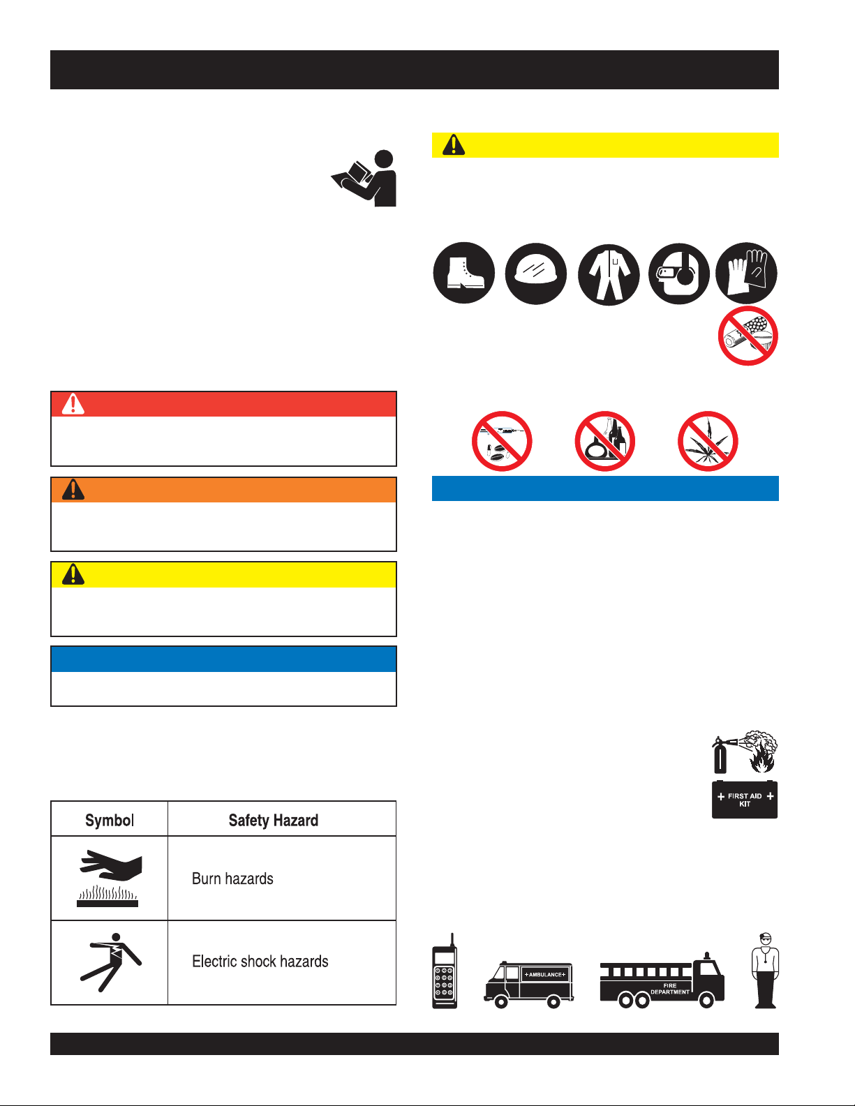
SAFETY MESSAGES
The four safety messages shown below will inform you
about potential hazards that could injure you or others. The
safety messages specifically address the level of exposure
to the operator and are preceded by one of four words:
DANGER, WARNING, CAUTION or NOTICE.
SAFETY SYMBOLS
DANGER
Indicates a hazardous situation which, if not avoided,
WILL result in DEATH or SERIOUS INJURY.
WARNING
GENERAL SAFETY
CAUTION
NEVER operate this equipment without proper protective
clothing, shatterproof glasses, respiratory protection,
hearing protection, steel-toed boots and other protective
devices required by the job or city and state regulations.
NEVER operate this equipment when not
feeling well due to fatigue, illness or when
under medication.
NEVER operate this equipment under the influence of
drugs or alcohol.
NOTICE
Indicates a hazardous situation which, if not avoided,
COULD result in DEATH or SERIOUS INJURY.
CAUTION
Indicates a hazardous situation which, if not avoided,
COULD result in MINOR or MODERATE INJURY.
NOTICE
Addresses practices not related to personal injury.
Potential hazards associated with the operation of this
equipment will be referenced with hazard symbols which
may appear throughout this manual in conjunction with
safety messages.
This equipment should only be operated by trained and
qualified personnel 18 years of age and older.
Whenever necessary, replace nameplate, operation and
safety decals when they become difficult read.
Manufacturer does not assume responsibility for any
accident due to equipment modifications. Unauthorized
equipment modification will void all warranties.
NEVER use accessories or attachments that are not
recommended by Multiquip for this equipment. Damage
to the equipment and/or injury to user may result.
ALWAYS know the location of the nearest
fire extinguisher.
ALWAYS know the location of the nearest
first aid kit.
ALWAYS know the location of the nearest phone or keep
a phone on the job site. Also, know the phone numbers
of the nearest ambulance, doctor and fire department.
This information will be invaluable in the case of an
emergency.
PAGE 4 — GB114BW GLOBUG SOLO LIGHTING SYSTEM — OPERATION & PARTS MANUAL — REV. #5 (01/06/09)
Page 5
GLOBUG SOLO LIGHTING SYSTEM — SAFETY iNFORMATION
LIGHTING SYSTEM SAFETY
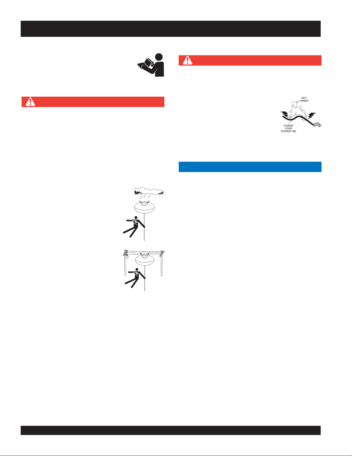
DANGER
NEVER use lighting system in rain, snow or
areas of high humidity that could generate
electrical storms.
WARNING
NEVER disconnect any emergency or safety devices.
These devices are intended for operator safety.
Disconnection of these devices can cause severe injury,
bodily harm or even death. Disconnection of any of
these devices will void all warranties.
CAUTION
NEVER attempt service on a running machine.
NOTICE
To prevent the lighting system from overturning, NEVER
use in winds that exceed 22mph (10 m/s).
The lighting system should only be used in temperatures
between 23° to 104°F (-5° to 40° C). Failure to comply
with these operating parameters could cause the lamp
to malfunction and shorten the ballast life.
NOTICE
NEVER leave any grease or oil residue on lamp surface
when replacing or removing lamp. This can create hot
spots, reducing the service life of the lamp.
ALWAYS make sure lamp surface is clean and dry.
ALWAYS replace with MQ recommended type lamp. See
parts section of this manual.
If applicable, ALWAYS make sure the lamp guard is
installed correctly. NEVER deform the lamp guard.
NEVER unplug the lamp’s AC power cable during
operation.
ALWAYS have a trained technician to install and
remove lamp or replace any damaged fixture wiring.
BALLOON SAFETY
WARNING
To prevent serious burns, NEVER touch
or unzip the balloon envelope when the
lamp is on.
CAUTION
ALWAYS keep the lighting system in proper running
condition.
Fix damage to lighting system and replace any broken
parts immediately.
ALWAYS store equipment properly when it is not being
used. Equipment should be stored in a clean, dry location
out of the reach of children and unauthorized personnel.
LAMP SAFETY
WARNING
NEVER attempt to replace lamp with the power on.
Always unplug the power cord from the generator or
power source when changing the lamp.
ALWAYS allow a sufficient amount of time for the lamp to cool
before changing. The possibility exists of severe burns.
CAUTION
NEVER use force when installing the lamp. Excessive force
could cause the lamp to break, causing bodily harm.
ALWAYS keep the balloon away from sharp objects and
excessive amounts of heat.
NOTICE
To prevent balloon deformation, NEVER use lighting
system in strong winds.
DO NOT place the balloon inside its protective cover
until the lamp has had a sufficient amount of time to cool
down. This will prevent the balloon’s nylon cover from
being burned (touching the lamp surface).
ALWAYS place the balloon inside its protective cover
after each use. This will prolong the life of the balloon
material, keeping it protected from harsh environmental
elements.
Replace balloon immediately if damaged. A damaged
balloon will not inflate properly, and may become more
damaged by touching the hot lamp surface.
DO NOT use excessive force when zipping and unzipping
the balloon. Be gentle with the zipper mechanism. If the
zipper is broken, the balloon will become unusable.
GB114BW GLOBUG SOLO LIGHTING SYSTEM — OPERATION & PARTS MANUAL — REV. #5 (01/06/09) — PAGE 5
Page 6
GLOBUG SOLO LIGHTING SYSTEM — SAFETY INFORMATION
GENERATOR SAFETY
If using a generator to power lighting system,
refer to applicable generator manual safety
information section.
ELECTRICAL SAFETY
DANGER
Lighting system is equipped with a ground pin on the
power plug. For your protection, ALWAYS complete the
grounding path. NEVER insert the AC power plug into a
2-prong receptacle to operate lighting system.
When applying power to the lighting system, ALWAYS
connect the AC power plug to a 3-prong receptacle that
is grounded. The possibility exists of electrical shock,
electrocution and even death if the lighting system is
not grounded.
NEVER operate lighting system or
handle any electrical equipment while
standing in water, while barefoot,
while hands are wet or in the rain. A
dangerous electrical shock could
occur, causing severe bodily harm
or even death.
Power Cord/Cable Safety
DANGER
NEVER let power cords or cables lay in water.
NEVER use damaged or worn cables or cords. Inspect
for cuts in the insulation
NEVER grab or touch a live power
cord or cable with wet hands. The
possibility exists of electrical shock,
electrocution or death.
Make sure power cables are securely connected.
Incorrect connections may cause electrical shock and
damage to the lighting system.
NOTICE
ALWAYS make certain that proper power or extension
cord has been selected for the job. See Cable Selection
Chart in this manual.
ALWAYS make sure the area above
the lighting system is open and clear
of overhead power lines and other
obstructions. Contact with overhead
power lines or other obstructions
could result in equipment damage,
electrical shock, electrocution and
even death.
PAGE 6 — GB114BW GLOBUG SOLO LIGHTING SYSTEM — OPERATION & PARTS MANUAL — REV. #5 (01/06/09)
Page 7
GLOBUG SOLO LIGHTING SYSTEM — SAFETY INFORMATION
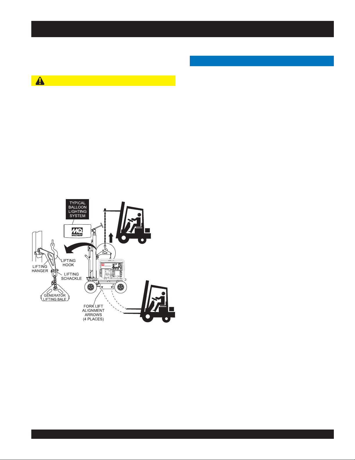
LOADING AND UNLOADING
If lighting system is equipped with a transport lifting hook,
refer to the following safety information.
CAUTION
Before lifting, make sure that lighting system parts are
not damaged and screws are not loosened or lost.
ALWAYS make sure crane or lifting device has been
properly secured to lifting hook of the equipment.
NEVER lift the equipment while lighting system is
running.
Make sure the mast is completely lowered before lifting
the lighting system.
Use adequate lifting cable (wire or rope) of sufficient
strength.
Use one point suspension hook and lift straight upwards.
TRANSPORTING SAFETY
NOTICE
When transporting the lighting system, if applicable,
always place in stow position and place mast in its
carrying case.
ALWAYS remove balloon/lamp assembly from the mast
when transporting lighting system. This will prevent
damage to the bulb due to vibration.
NEVER leave the balloon/lamp exposed during transport.
Exposure to excess wind or rain could damage the
balloon’s nylon cover.
ALWAYS place balloon inside its protective cover during
transport. Be sure the cover is secured tightly around the
balloon/lamp assembly.
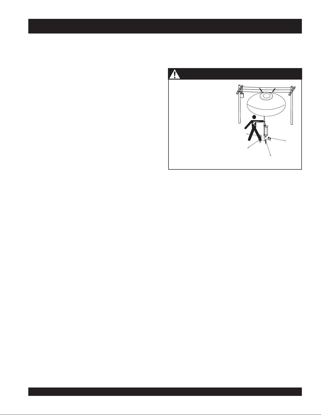
DANGER - Grounding the GloBug Solo for Operation
Never allow any person or animal to stand underneath the
equipment while lifting.
DO NOT lift machine to unnecessary heights.
GB114BW GLOBUG SOLO LIGHTING SYSTEM — OPERATION & PARTS MANUAL — REV. #5 (01/06/09) — PAGE 7
Page 8
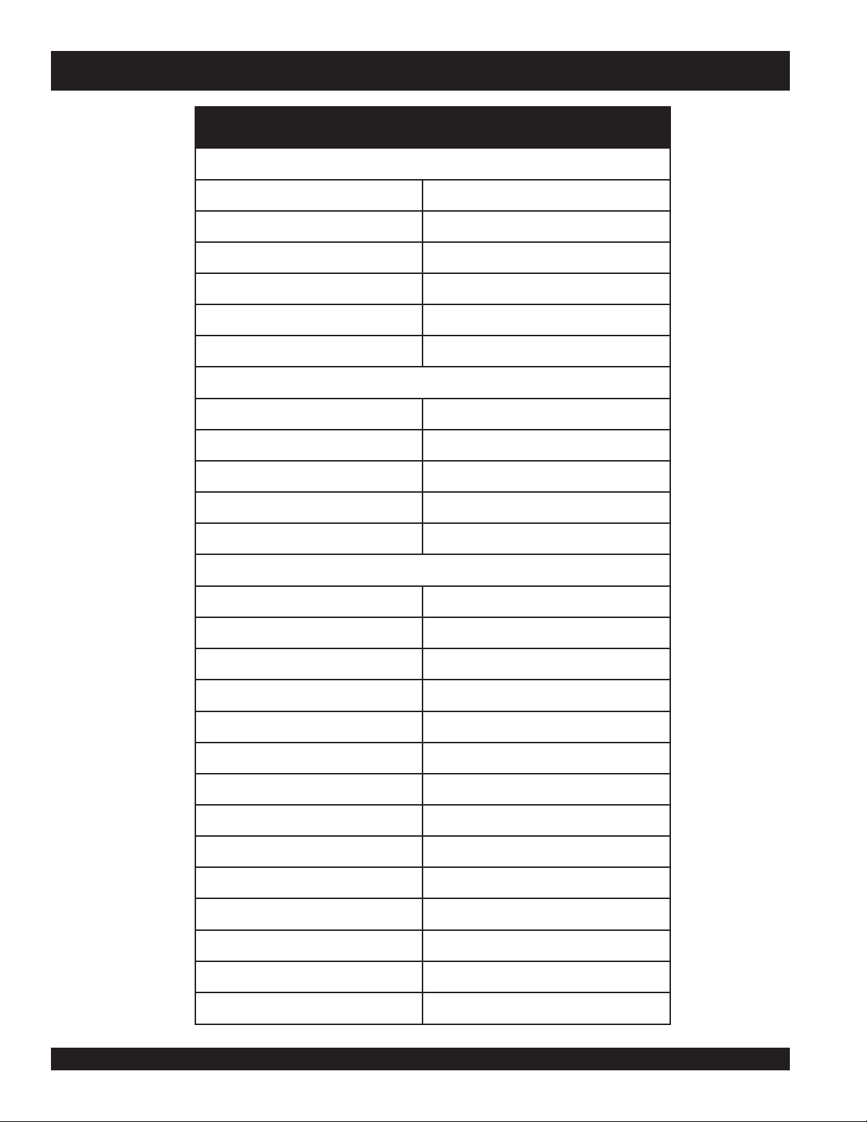
GLOBUG SOLO LIGHTING SYSTEM — SPECIFICATIONS
snoitacificepS.1elbaT
oloSguBolG
ledoMWB411BG
egatloVtupnICAV021
ycneuqerFesahP-elgniSzH06
tnerruC.xaMspmA5.9
dniW)hpk64.08(hpm56
thgieW)gk95(.sbl031
pmaL
epyTpmaLedilaHlateMttaW0001)1(
snemuL000,211
)°063(egarevoCthgiL)s
rotoMnaF
rotoMnaFnoollaBzH06,CAV511
tnerruC.xaMspmA063.
erusserP)APk6.512(ISP62.13
noollaB
retem
aiD)sretem1.1(.tf9.3
rotareneGhtiwytilibatS
)lanidutignoL(erutarepmeTecafruS.xaM)C°742(F°6.674
)lasrevsnarT(erutarepmeTecafruS.xaM)
retem27.54(.tf051
C°412(F°2.714
lairetaMnolyNtnatsiseRtaeH
erutarepmeTgnitsiseRtaeH)C°081~°061(F°653~°023
nitleM)C°062(F°005
tsaM
snoisnemiD
PAGE 8 — GB114BW GLOBUG SOLO LIGHTING SYSTEM — OPERATION & PARTS MANUAL — REV. #5 (01/06/09)
erutarepmeTg
noollaBfoerutarepmeTlanretnIegarevA)C°25(F°621
ecnatsiseRretaWHmm005,1
segatSforebmuN)elopnoisnetxehtiw4(3
thgieHmumixaM)sretem5(teef5.61
0
2
2elbaT,2erugiFeeS
Page 9
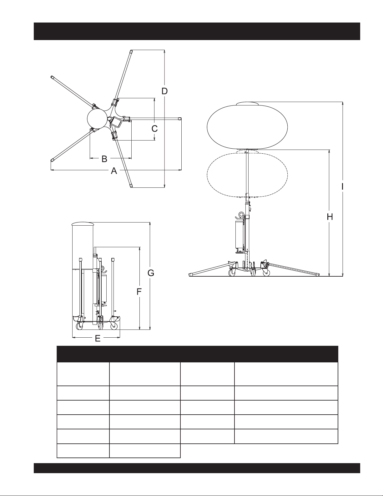
GLOBUG SOLO LIGHTING SYSTEM — DIMENSIONS
Figure 2. Dimensions
SNOISNEMID.2ELBAT
ecnerefeR
retteL
A).mm929,1(.tf33.6F ).mm912,1(.tf0.4
B).mm9
C).mm906(.tf2H ).mm223,3-358,1(.tf9.01-80.6
D).mm046,2(.tf66.8I ).mm6883-935,2(-.tf57.2
E).mm017(.tf33.2
GB114BW GLOBUG SOLO LIGHTING SYSTEM — OPERATION & PARTS MANUAL — REV. #5 (01/06/09) — PAGE 9
06(.tf2G ).mm006,1(.tf52.5
).mm(.tfnoisnemiD
ecnerefeR
retteL
1-33.8
).mm(.tfnoisnemiD
Page 10
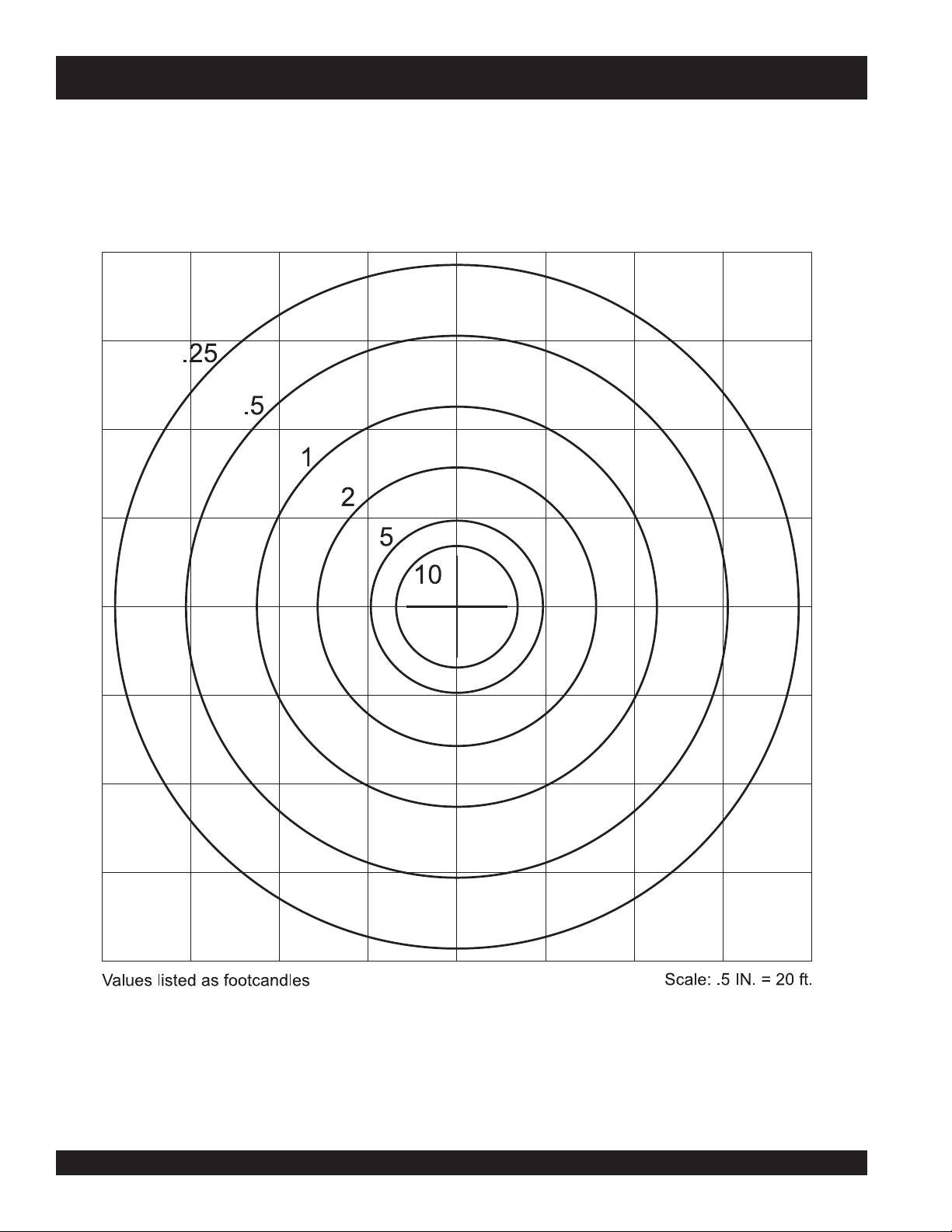
GLOBUG SOLO LIGHTING SYSTEM — FLOODLIGHT FOOTCANDLE PLOT
Based on 360°glare-free coverage.
Figure 3. Floodlight Footcandle Plot (Bal120-Standard)
PAGE 10 — GB114BW GLOBUG SOLO LIGHTING SYSTEM — OPERATION & PARTS MANUAL — REV. #5 (01/06/09)
Page 11
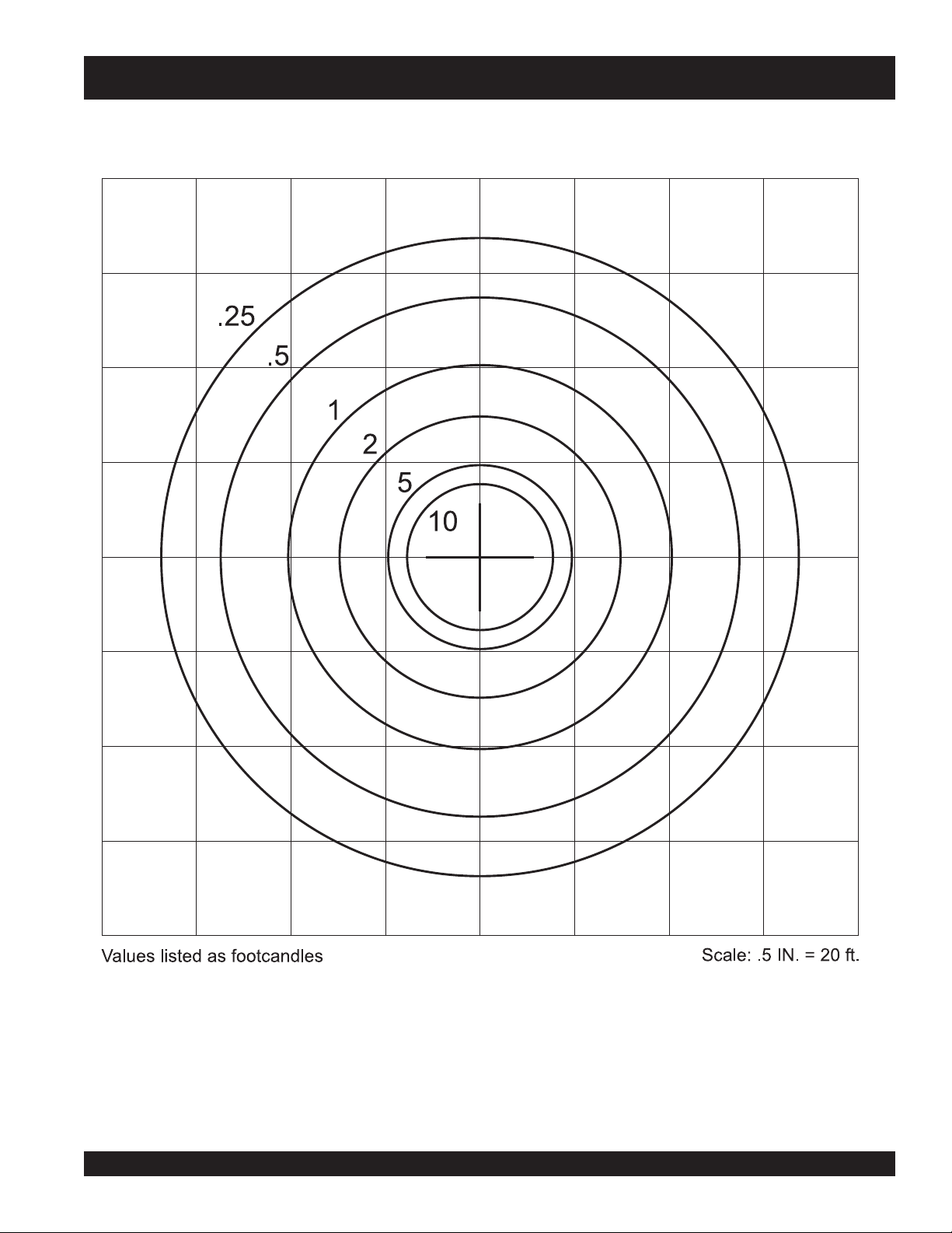
GLOBUG SOLO LIGHTING SYSTEM — FLOODLIGHT FOOTCANDLE PLOT
Based on 360°glare-free coverage.
Figure 4. Floodlight Footcandle Plot (BAL120R-Reflector)
GB114BW GLOBUG SOLO LIGHTING SYSTEM — OPERATION & PARTS MANUAL — REV. #5 (01/06/09) — PAGE 11
Page 12
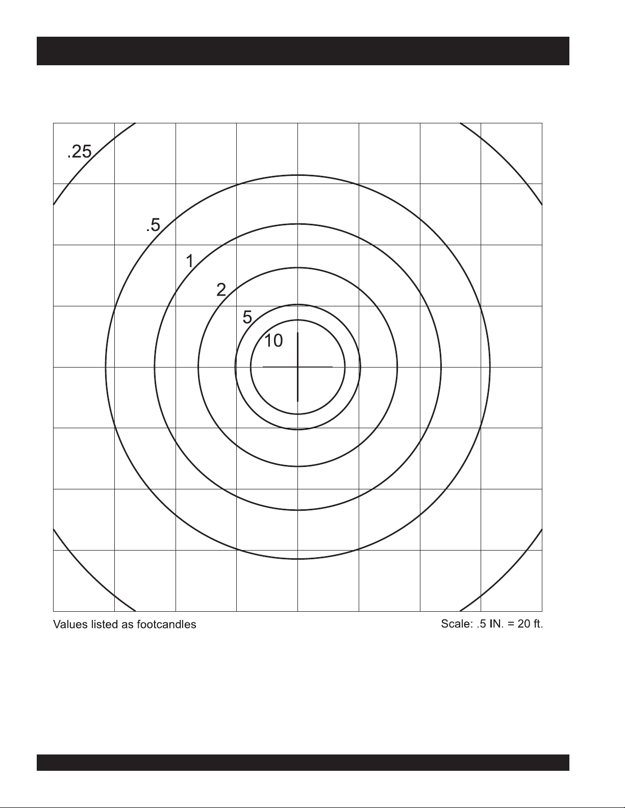
GLOBUG SOLO LIGHTING SYSTEM — FLOODLIGHT FOOTCANDLE PLOT
360 degree coverage
Figure 5. Floodlight Footcandle Plot (BAL115D-Drum Shaped)
PAGE 12 — GB114BW GLOBUG SOLO LIGHTING SYSTEM — OPERATION & PARTS MANUAL — REV. #5 (01/06/09)
Page 13
GLOBUG SOLO LIGHTING SYSTEM — GENERAL INFORMATION
The Multiquip GloBug Solo Lighting System is a general
purpose floodlight tower intended for emergency and remote
lighting conditions. Power requirements for running the GloBug
The lighting system can be raised vertically in excess of 16.5 feet
(5 meters) . Outriggers must always be deployed prior to raising
the mast.
Solo are 120 VAC, 60 Hz @ 9.5 amps. The GloBug Solo can
be plugged into a standard 120 VAC wall receptacle.
DANGER - GloBug Solo Overhead Obstructions
The lighting system of Multiquip's GloBug Solo is comprised
of one "Metal Halide" 1000-watt lamp. This lamp has an
output of 112,000 lumens. Typical lighting coverage is in
excess 150 ft. (45.72 meters) in a 360 degree pattern.
Located on the side of the mast is a weather-resistant
ballast box that contains the ballast for starting the lamp.
The lamp is activated by an ON/OFF switch located at
the base of the ballast.
For ease of service or transport, the lamp is equipped with
a quick-disconnect connector that allows the lamp fixture to
be removed quickly. This feature is extremely useful during
transport of the GloBug Solo over rough terrain. It is always
ALWAYS make sure the
area above GloBug Solo is
open and clear of overhead
power lines and other
obstructions. The tower
extends in excess of 16.5 ft.
(5 meters). Contact with
overhead power lines or
other obstructions could
result in equipment
damage,
or death
best to remove the lamp and pack it safely so it will not be
damaged.
Alarm Buzzer
serious injury
!
Balloon Envelopes
The GloBug Solo can be configured with a variety of balloon
envelopes (canopy). Please contact the MQ sales department
for the balloon of your choice. The GloBug Solo, Model
GB114BW comes with the standard balloon (BAL-120).
The GloBug Solo is equipped with a "Balloon Alarm" feature.
This alarm will sound if the lamp is on and the balloon attempts
to make contact with the
is intended to inform the operator that a potential burn hazard
exists between the lamp surface and the balloon material.
Always allow the lamp to cool down before removing the AC
power from the GloBug Solo. In the event the balloon begins
to deflate during normal operation, immediately place the
GloBug Solo's ON/OFF switch in the OFF position.
hot
surface of the lamp. This alarm
GB114BW GLOBUG SOLO LIGHTING SYSTEM — OPERATION & PARTS MANUAL — REV. #5 (01/06/09) — PAGE 13
Page 14
GLOBUG SOLO LIGHTING SYSTEM — COMPONENTS
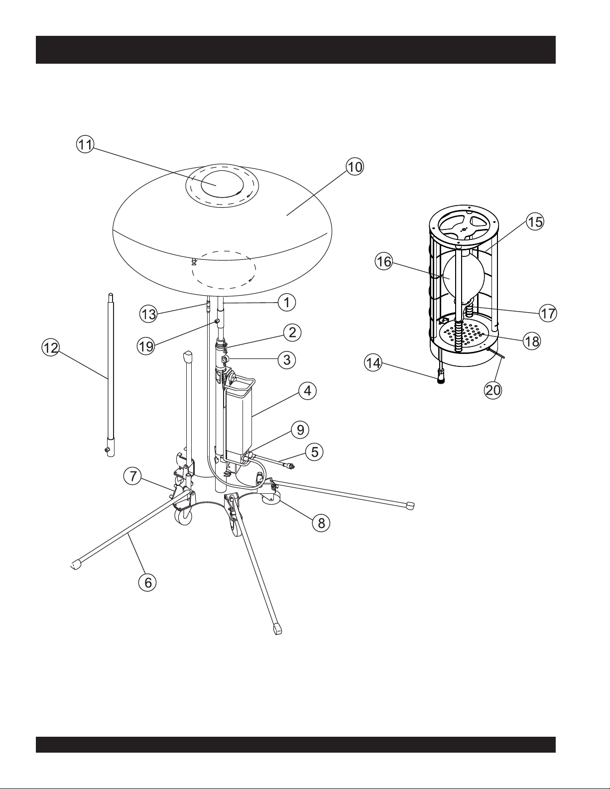
Figure 6. Major Components
PAGE 14 — GB114BW GLOBUG SOLO LIGHTING SYSTEM — OPERATION & PARTS MANUAL — REV. #5 (01/06/09)
Page 15

GLOBUG SOLO LIGHTING SYSTEM — COMPONENTS
Figure 6 shows the location of the controls and components
for the GloBug Solo Lighting System. The function of each
control is described below:
1. Mast – This mast is comprised of three separate stages
(four - with extension pole). The mast can be raised in
excess of 16.5 ft. (5 meters). When raising the mast,
always be on the lookout for overhead obstructions.
Never adjust the mast with the balloon off to prevent mast
from shooting up and causing injury.
2. Mast Release Latch– Use this latch to raise the mast by
pushing down the mast and then releasing the latch.
Always be on the lookout for overhead obstructions.
Keep immediate area free of bystanders and debris when
raising the mast.
3. Mast Lock Lever – Use this lock to keep mast in place
after the mast height has been adjusted.
4. Ballast – Provides the necessary electronics to light the
lamp.
5. AC Power Cable – Connect this cable to a 120 VAC, 60
Hz power source.
6. Outriggers – ALWAYS deploy the outriggers when
raising the mast.
7. Counter-Weight Lever – Locks the outriggers in place
when they are deployed.
8. Wheels – The GloBug Solo uses 5 caster wheels. To
prevent the Globug Solo from moving, always lock 3
caster wheels.
9. ON/OFF Switch – Place this switch in the ON position
to turn on the lamp. To turn off the lamp place in the OFF
position. Please wait for approximately 10 minutes before attempting to turn the lamp back on.
13. Lamp Power Cable (Ballast) – Connect this quick-
disconnect cable plug (ballast-side) to the balloon lamp
power cable plug.
14. Lamp Power Cable (Balloon) – Connect this quick-
disconnect cable plug (balloon-side) to the ballast lamp
power cable plug.
15. Lamp Guard – This guard (cage) protects the lamp from
being hit by objects.
16. Lamp – 1000 watt metal-halide type lamp. Replace only
with MQ recommended type lamp. Always allow a
sufficient amount of time for the lamp to
before changing.
17. Lamp Holder – Screw lamp into this holder. If lamp
becomes difficult to screw into holder or holder is
damaged, replace holder.
18. Fan Motor (Blower) – This electric motor is responsible
for inflating the balloon. It will supply a pressure of 31.26
psi (215.6 kPA). Please note that the balloon will begin to
inflate as soon as power is applied to the GloBug Solo.
The OFF/ON switch
motor.
19. T-Handle Bolt Lock – Always tighten this lock to hold the
lamp/balloon securely in place before raising mast.
20. Balloon Alarm Buzzer – Will sound during normal
operation if the balloon attempts to make contact with the
lamp's
place the GloBug Solo's ON/OFF switch in the OFF
position.
cool down
does not
hot
surface. If this condition occurs, immediately
control the electric fan
10. Balloon – This balloon is made of heat-resistant nylon,
with a diameter of 3.9 ft. (1,150 mm). The balloon shall be
inflated to a pressure of 31.26 psi (215.6 kPA).
11. Balloon Cover – Covers the balloon when not in use.
Allow a sufficient amount of time for the lamp to cool
down before covering balloon. Possibility exists of balloon getting burned.
12. Extension Pole – extends the height of the mast when
needed.
GB114BW GLOBUG SOLO LIGHTING SYSTEM — OPERATION & PARTS MANUAL — REV. #5 (01/06/09) — PAGE 15
Page 16

GLOBUG SOLO LIGHTING SYSTEM — PRE-SETUP
CAUTION - READ MANUAL
Please read this entire manual carefully
before attempting to operate the GloBug
Solo. Failure to read this manual could
cause damage to the GloBug Solo and
serious injury to the operator.
GloBug Solo Setup
1. Place the GloBug Solo on a
will not slide or turn over. Make sure there is enough
space around the GloBug Solo for the outriggers to be
deployed.
2. Lock the three caster wheels (two wheels have no locks)
by stepping on the red end (S) of the caster lever
(Figure 7).
firm level surface
so that it
4. Expose the balloon by pulling down on the velcro tabs
and unzipping the protective cover as shown in Figure
9. Next, fold the protective cover into itself and zip.
5. Before raising the mast, make sure the T-Handle Bolt
Lock (Figure 10) is securely tightened. This will prevent
the balloon/lamp assembly from falling off. In addition
make sure that the lamp power cable (balloon) is
connected to the lamp power cable (ballast).
Figure 9. Exposing the Balloon.
6. Push down the mast and unhook the Mast Release Latch
Figure 7. Locking Caster Wheels
3. Pull outriggers downward at the ends until they lock in
place in the ground (Figure 8).
Figure 8. Outriggers (Deployed Position)
(Figure 10). Extend the mast to the desired height.
Figure 10. T-Handle Bolt Lock and Mast Release Latch
DANGER SPRING LOADED MAST
The mast is spring loaded and will automatically extend when
unhooked. NEVER extend the mast with balloon or lamp
removed. The possibility exists of the mast rapidly shooting
upward.
PAGE 16 — GB114BW GLOBUG SOLO LIGHTING SYSTEM — OPERATION & PARTS MANUAL — REV. #5 (01/06/09)
Page 17

GLOBUG SOLO LIGHTING SYSTEM — PRE-SETUP
CAUTION - MAST PINCH POINT
When raising or lowering the mast, keep hands and fingers
clear of the various mast sections. This will prevent hands
and fingers from getting pinched (Figure 11).
Figure 11. Pinch Point
7. When the desired height is achieved, lock the mast in
place with the Mast Lock Lever (Figure 12).
NEVER lock the Mast Lock Lever with balloon or lamp removed.
The possibility exists of the mast rapidly shooting upward.
Figure 12. Mast Lock Lever
DANGER SPRING LOADED MAST
NEVER release the latch with balloon or lamp removed.
Make sure latch is hooked before balloon or lamp is removed.
GB114BW GLOBUG SOLO LIGHTING SYSTEM — OPERATION & PARTS MANUAL — REV. #5 (01/06/09) — PAGE 17
Page 18

GLOBUG SOLO LIGHTING SYSTEM — OPERATION
DANGER - HIGH VOLTAGE POWER LINES
When raising mast, ALWAYS be on
the lookout for overhead obstructions
such as high voltage power lines. The
possibility exists of electrocution,
even death if the GloBug Solo comes
in contact with
Applying Power
1. Make sure the power ON/OFF switch (Figure 13) located
near the bottom of the ballast is in the OFF position.
Figure 13. Power OFF/ON Switch (OFF Position)
high voltage power lines
.
4. Notice that the balloon envelope will begin to deploy as
soon as power is applied. This function
by the power ON/OFF switch.
5. Wait until the balloon is fully deployed before attempting
to turn on the lamp. The possibility exists of the balloon
getting burned (touching the lamp).
6. If the balloon is fully deployed, place the GloBug Solo's
ON/OFF switch in the ON position (Figure 15).
Figure 15. Power OFF/ON Switch (ON Position)
7. The lamp should now be on. If the lamp is not on, check
all connections and repeat steps 1 through 6. If the lamp
still does not come on, contact the MQ service
department.
is not
controlled
2. The GloBug Solo has a power requirement of 120 VAC,
60 Hz @ 9.5 amps. Connect the GloBug Solo's AC power
cord to a 120 VAC power receptacle (Figure 14).
Figure 14. 120 VAC Receptacle
Shutdown
1. Place the power ON/OFF switch (Figure 16) in the OFF
position.
Figure 16. Power OFF/ON Switch (OFF Position)
CAUTION - LAMP COOL DOWN
Allow a sufficient amount of time (15-20 minutes) for the
lamp (Figure 17) to
power cable from power receptacle. The possibility exists
of the balloon getting burned (touching the lamp).
2. Disconnect the GloBug Solo's AC power cable from the
power receptacle. The balloon should begin to deflate.
cool down
before disconnecting
PAGE 18 — GB114BW GLOBUG SOLO LIGHTING SYSTEM — OPERATION & PARTS MANUAL — REV. #5 (01/06/09)
Page 19

GLOBUG SOLO LIGHTING SYSTEM — SHUTDOWN
Figure 17. Hot Lamp Surface
3. Push down the mast and unhook the Mast Release Latch
(Figure 10).
the desired height.
4. When the mast if fully lowered, lock the mast in place
with the Mast Lock Lever (Figure 12).
6. Unzip the protective cover as shown in Figure 18, and
place cover over balloon/lamp assembly. Fully zip
protective cover and fold velcro tabs in place.
Fully lower
the mast. Extend the mast to
7. Wrap the AC power cable and lamp power cable around
the ballast frame.
Figure 20. Outriggers (Stow Position)
Figure 18. Covering the Lamp/Balloon Assembly
7. To unlock outriggers, push downward on the
counterweight lever indicated by arrow (Figure 19). Grab
hold of outrigger, pull upward, and place in stow position
(Figure 20)..
8. Step on the blue end of the caster lever (Figure 21) on
the three caster wheels to unlock them. The GloBug
Solo can now be moved.
Figure 21. Unlocking Caster Wheels
Storage
1. Wipe and dirt or foreign matter that may have
accumulated on the GloBug Solo during operation. Use
a mild detergent to clean the unit. DO NOT spray with
water.
2. Avoid storing the GloBug Solo in areas that can be
exposed to rain, harsh elements, and high humidity.
3. Place the GloBug Solo in a clean dry location away from
dirt and debris.
Figure 19. Outriggers (Released)
GB114BW GLOBUG SOLO LIGHTING SYSTEM — OPERATION & PARTS MANUAL — REV. #5 (01/06/09) — PAGE 19
Page 20

GLOBUG SOLO LIGHTING SYSTEM — MAINTENANCE
CAUTION - READ SAFETY GUIDELINES
Before performing any maintenance
procedures, be sure to READ the lamp,
balloon, and general safety guidelines in
this manual. Failure to
understand
could cause severe equipment damage
and bodily harm.
Removing the Lamp/Balloon Assembly
1. Loosen the T-Handle Bolt Lock (Figure 22) that secures the
lamp to the mast.
these safety guidelines
read
and
CAUTION - BALLOON ZIPPER SAFETY
DO NOT use excessive force when zipping or
unzipping the balloon. The possibility exists
of the zipper tearing, which would make the
balloon unusable.
2. Unzip the zipper (Figure 23) at the bottom of the balloon
and roll the balloon envelope upwards to expose the lamp
(Figure 24). Remove the lamp guard to gain access to the
lamp.. DO NOT use excessive force when unzipping the
balloon.
Figure 22. Loosening the Balloon/Lamp
3.
Disconnect the lamp power cable (Figure 6) and slide the
balloon/lamp forward from the mast adapter stand. Place
lamp/balloon assembly on a suitable work bench that is
free of dirt, and sharp objects that could damage the
balloon.
Removing the Lamp
1. Expose the balloon (Figure 23) by pulling down on the
velcro tabs and unzip the protective cover as shown in
Figure 19. Next, fold the protective cover into itself and
zip.
3. Push down and hold the lamp holder (spring loaded) away
from the lamp (Figure 25). Unscrew the lamp (turn
counterclockwise) from the lamp socket.
Figure 24. Removing the Lamp Guard
Figure 23. Exposing the Balloon
PAGE 20 — GB114BW GLOBUG SOLO LIGHTING SYSTEM — OPERATION & PARTS MANUAL — REV. #5 (01/06/09)
Figure 25. Removing the Lamp
Page 21

GLOBUG SOLO LIGHTING SYSTEM — MAINTENANCE
Installing a New Lamp
1. When installing a new lamp (Figure 26) use only MQ
recommended type lamp. See parts section of this
manual. Failure to use correct type lamp could adversely
affect lighting capability and may cause damage to the
equipment.
2. Push down and hold the lamp holder (spring loaded) away
from the lamp. Screw the lamp (turn clockwise) into the
lamp socket. Gently place the lamp holder firmly over
the top of the lamp. This will prevent the lamp from
touching the lamp guard or pipe frame.
2. Zip up the zipper at the bottom (Figure 24) of the balloon
and pull down the balloon envelope to cover the lamp
3. Place the lamp/balloon assembly back onto the mast.
4. Tighten the T-Handle Bolt Lock to secure the lamp to the
mast.
5. Reinstall the protective cover over the balloon/lamp assembly. Be sure to fold the velcro tabs.
6. Reconnect the power cables.
Replacing the Balloon
1. Follow the procedures as outlined in the "Removing the
Balloon Lamp" assembly section.
2. Unzip the zipper at the bottom and top of the balloon.
Slide the balloon over the top of the lamp guard as shown
in Figure 28.
Figure 26. Installing the Lamp
Re-Installing the Lamp/Balloon Assembly
1. Reinstall the lamp guard (Figure 27). Be careful not to install
the lamp guard in the wrong direction.
Figure 27. Installing the Lamp Guard
3. Slide the new balloon over the top of the lamp guard as
shown in Figure 29. Zip up the zipper at the bottom and
top of the balloon.
Figure 28. Removing the Balloon
Figure 29. Removing the Balloon
GB114BW GLOBUG SOLO LIGHTING SYSTEM — OPERATION & PARTS MANUAL — REV. #5 (01/06/09) — PAGE 21
Page 22

GLOBUG SOLO LIGHTING SYSTEM — MAINTENANCE
Ballast Box Removal
WARNING - HOT SURFACE (BALLAST)
Dangerous conditions exists inside the ballast
compartment. Please use extreme caution when
performing maintenance on the ballast box.
NEVER touch the ballast or ballast cover while
the lamp is on. These components generate an
extreme amount of heat, which makes their surfaces very
ALWAYS allow the ballast box and cover surface to cool down
before servicing.
hot!.
DANGER - HIGH VOLTAGE (BALLAST)
The electronic components of the ballast
generate high voltage conditions. These
conditions can be
harm, even death.
maintenance or troubleshooting, have only
experience personnel work on the ballast.
lethal and cause bodily
When performing
2. Disconnect the AC power cable and Lamp Power Cable from
the ballast (Figure 31).
Figure 31. Cable Disconnection
1. Remove cable clamp from the hook located under the
balloon (Figure 30).
3. Unscrew and remove the knob bolt that attaches the ballast
to the mast (Figure 32).
4. Unhook the bottom of the ballast from the slot on the mast
and detach the ballast from the mast.
Figure 30. Cable Clamp
Figure 32. Ballast Removal
PAGE 22 — GB114BW GLOBUG SOLO LIGHTING SYSTEM — OPERATION & PARTS MANUAL — REV. #5 (01/06/09)
Page 23

GLOBUG SOLO LIGHTING SYSTEM — MAINTENANCE
Filter Replacement
WARNING - HOT SURFACE (LAMP FRAME)
DO NOT replace filter immediately, allow a
sufficient amount of time for the lamp assembly
to cool down before changing filter.
1. Remove the balloon as described in the "Removing the
Lamp/Balloon" section.
2. Disconnect the lamp power cable (Figure 6).
3. Rotate the balloon/lamp base assembly so that the filter
is facing upwards. See Figure 30.
5. Install a new filter over the brace as shown in Figure 32.
Be sure to align the
CAUTION - FILTER ALIGNMENT
When placing the filter element, always align the cut of
the filter on top of the brace. This will keep the filter from
being dislodged and getting damaged.
cut of the filter
Figure 32. Filter Placement
over the brace.
Figure 30. Balloon/Lamp Placement
4. Turn the three locking tabs (Figure 31) inward to release
the plate. Remove plate and filter.
6. Turn the three retaining tabs (Figure 33) outward so that
they touch the lamp base.
Figure 33. Filter/Plate Install
Figure 31. Filter Removal
GB114BW GLOBUG SOLO LIGHTING SYSTEM — OPERATION & PARTS MANUAL — REV. #5 (01/06/09) — PAGE 23
Page 24

GLOBUG SOLO LIGHTING SYSTEM — MAINTENANCE
PAGE 24 — GB114BW GLOBUG SOLO LIGHTING SYSTEM — OPERATION & PARTS MANUAL — REV. #5 (01/06/09)
Page 25

GLOBUG SOLO LIGHTING SYSTEM — MAINTENANCE
For a prolonged life cycle an extended quality follow the
recommended GloBug Solo service guidelines as referenced
in Table 3.
ERUGIFTRAPMETIKCEHCNOITULOS
ECNANETNIAMDNAKCEHCCIDOIREP.3ELBAT
1LepiPemarF?deweksepipemarF.ecalpeR
2LredloHpmaL?esoolredlohpmaL.ecalperronethgiT
pmaL
noollaB
tsaM
retsaC
3L)esaB(pmaL?esoolesabpmaL.ylerucesniwercS
4LpmaL?pmalevitcefeD.ecalpeR
5LrotcennoC/elbaC?esoolrodetcennocsidelbaC.ylerucestcennoC
1B)epolevnE(noollaB?ytridroevitcefeD.ecalpeR
2BreppiZ?nekorB.ecalpeR
3B)rewolB(rotoMnaF?ylreporpgnikrowtoN.ecalperroriapeR
1MhctaLesaeleRtsaM?esooltloB.ylerucesnethgiT
2MeloPtsaM?degamaD.ecalpeR
3MreveLkcoLtsaM?ylreporpgnikrowtoN.riapeR
1CreggirtuO?ylhtoomsgnivomtoN.esaergyarpS
2CtekcoSeloP?depmalcylerucestoN.ylerucespmalC
1EelbaCrewoP?elbacnrowroevitcefeD.ecalpeR
❖
❖
❖
❖
■
❖
❖
❖
■
❖
▲
●
❖
❖
cirtcelE
GB114BW GLOBUG SOLO LIGHTING SYSTEM — OPERATION & PARTS MANUAL — REV. #5 (01/06/09) — PAGE 25
2EgulP?degamaD.ecalpeR
3EhctiwSpmaL?ylreporpgnikrowtoN.ecalpeR
kcehCyliaD-
❖
■
sruoH02yrevE-
●
sruoh001yrevE-
▲
❖
❖
sruoh005yrevE-
Page 26

GLOBUG SOLO LIGHTING SYSTEM — TROUBLESHOOTING (LAMPS)
Practically all breakdowns can be prevented by proper
handling and maintenance inspections, but in the event of a
breakdown, please take a remedial action following the
diagnosis based on the Lamp Troubleshooting (Table 4)
information shown below.
MOTPMYSMELBORPELBISSOPNOITULOS
?detcennocsidgulpsI.yltcerrocni
?ffodehctiwsrewoppmalsI.hctiwsnonruT
?esoolpmalsI .tekcosotniylerucespmalwercS
tcatnocsI .rotcatnocdetcennocsidtcennoC
.thgiltonseodpmaL
aht
?ecruos
If the problem cannot be remedied, please leave the unit
just as it is and consult or company's service department.
?esoolrodetcennocsidro
rehto(secnailppacirtcelerehtoynaerA
rewopotnideggulp)rewotthgiln
?elbitapmocnipmalfoledomsI.pmalQMeniunegesU
GNITOOHSELBUORTPMAL.4ELBAT
gulP
.secnailpparehtollagulpnU
onpmalsI
)niagapmalnogninruterofeb
nopmaL
.emittrohs
.etalfni
arofsthgilyl
?)C°04(F°401
tonseodnoollaB
polevnenoollabsI .epolevnenoollabecalperroriapeR
?evitcefede
?niagathgilothguonelooct
deriuqersisetunim03ot02folavretnI(
nahterom(hgihooterutarepmettneibmasI
?ylreporpgnikrowton)rewolb(rotomnafsI .)rewolb(rotomnafriaperrokcehC
.nwodloocotpmalroftiaW
reporpsierehterehwpmalevoM
v
.noitalitne
PAGE 26 — GB114BW GLOBUG SOLO LIGHTING SYSTEM — OPERATION & PARTS MANUAL — REV. #5 (01/06/09)
Page 27

GLOBUG SOLO LIGHTING SYSTEM — TROUBLESHOOTING (MAST)
Practically all breakdowns can be prevented by proper
handling and maintenance inspections, but in the event of a
breakdown, please take a remedial action following the
diagnosis based on the Mast Troubleshooting (Table 5)
information shown below.
MOTPMYSMELBORPELBISSOPNOITULOS
ebtonnactsaM
.desiar
ebtonnactsamehT
.derewol
?dekcolreveLkcoLtsaMsI.reveLk
?dekcolreveLkcoLtsaMsI.reveLkcoLtsaMesaeleR
If the problem cannot be remedied, please leave the unit
just as it is and consult or company's service department.
GNITOOHSELBUORTTSAM.5ELBAT
coLtsaMesaeleR
GB114BW GLOBUG SOLO LIGHTING SYSTEM — OPERATION & PARTS MANUAL — REV. #5 (01/06/09) — PAGE 27
Page 28

GLOBUG SOLO LIGHTING SYSTEM — WIRING DIAGRAM (S/N G20070 & BELOW)
P1
BLK (LINE)
CHASSIS
GND
SPLICE
YEL
BLK
GRN
BLK
J1
2
4
120 VAC, 60Hz
INPUT BALLAST
POWER CABLE
WHT (NEUTRAL)
S1
OFF/ON
SWITCH
BLK
FRONT VIEW
BALLAST
RECEPTACE
(FEMALE)
1
RED
3
WHT
MALE
NOT USED
RED
RED
WHT
ORANGE
PURPLE
BLACK
24 µF
@480 VDC
CAPACITOR
C1
RED (HOT)
208 VAC
240 VAC
277 VAC
TRANSFORMER
RED/BLK YEL YEL
RED
METAL HALIDE
T1
(BALLAST)
120 VACCOMCAP
BLK/YEL
1000 WATT
LAMP
LAMP
POWER
CABLE
FEMALE
FRONT VIEW
LAMP CABLE
MALE PLUG
(W1)
GRN
WHT
GRN (NEUTRAL)
BUZZER
B1
WHT
DS1
S2
S3
MICRO-SWITCH
WITH SENSOR
BLK
WHT
RED
WHT
2
1
3
4
P2
REF.
DESC.
P1
Input Power Cable Assy.(Ballast) A300066700
Ballast Output Receptacle
J1
Lamp Fan Cable Assy. (Input)
P2
DS1
1000 Watt Metal Halide Lamp E000009800
24 µF Capacitor @ 480 VDC
C1
Ballast (Transformer) A300033800
T1
GRN
BLK
16 AWG.
DESCRIPTION
BLK
TABLE 6. REFERENCE DESIGNATIONS
PART NUMBER
A400037600
A300033600
19598
BLUE
BLK
REF.
DESC.
M1
B1
S1
S2
S3
W1
DESCRIPTION
Fan Motor Assy. A300033500
Buzzer Alarm Balloon E000030100
ON/OFF Switch A400037502
Micro-Switch 1400150210
Micro-Switch Cap 1400150410
Lamp Power Cable A300083800
FAN
MOTOR
BLK
PART NUMBER
M1
PAGE 28 — GB114BW GLOBUG SOLO LIGHTING SYSTEM — OPERATION & PARTS MANUAL — REV. #5 (01/06/09)
Page 29

GLOBUG SOLO LIGHTING SYSTEM — WIRING DIAGRAM (S/N G20071 & ABOVE)
FAN
MOTOR
1000 WATT
METAL HALIDE
LAMP
ORANGE
PURPLE
BLACK
NOT USED
RED/BLK YEL YEL
BLK/YEL
CAPACITOR
24µF
@480 VDC
TRANSFORMER
(BALLAST)
BLK
RED
120 VACCOMCAP
WHT (NEUTRAL)
RED (HOT)
BLK
WHT
BLK
BLUE
BUZZER
MICRO-SWITCH
WITH SENSOR
TABLE 6. REFERENCE DESIGNATIONS
P1
P2
J1
REF.
DESC.
DESCRIPTION
PART NUMBER
Input Power Cable Assy.(Ballast) A300066700
Lamp Fan Cable Assy. (Input)
A400079400
A300105500
DS1
1000 Watt Metal Halide Lamp E000009800
C1
24 µF Capacitor @ 480 VDC 19598
T1
Ballast (Transformer) A300033800
M1
B1
S2
S3
REF.
DESC.
DESCRIPTION
PART NUMBER
Fan Motor Assy. A300033500
Buzzer Alarm Balloon E000030100
Micro-Switch 1400150210
Micro-Switch Cap 1400150410
B1
S2
S3
16 AWG.
208 VAC
240 VAC
277 VAC
T1
C1
M1
WHT
BLK
WHT (NEUTRAL)
RED
120 VAC, 60Hz
INPUT BALLAST
POWER CABLE
2
1
3
J1
4
S1
Ballast Output Receptacle
OFF/ON
SWITCH
BLK
S1
ON/OFF Switch A400037502
DS1
WHT
FRONT VIEW
LAMP CABLE
MALE PLUG
2
1
3
P2
4
FRONT VIEW
BALLAST
RECEPTACE
(FEMALE)
RED
SPLICE
RED
GRN
WHT
BLK (LINE)
GRN
P1
LAMP
POWER
CABLE
(W1)
RED
BLK
W1
Lamp Power Cable A300083900
MALE
FEMALE
CHASSIS
GND
GRN
GRN
BLK
BLK
WHT
GND
GRN
GB114BW GLOBUG SOLO LIGHTING SYSTEM — OPERATION & PARTS MANUAL — REV. #5 (01/06/09) — PAGE 29
Page 30

EXPLANATION OF CODE IN REMARKS COLUMN
The following section explains the different symbols and
remarks used in the Parts section of this manual. Use the help
numbers found on the back page of the manual if there are any
questions.
The contents and part numbers listed in the parts section are
subject to change
guarantee the availability of the parts listed.
Sample Parts List:
NO. PART NO. PART NAME QTY. REMARKS
1 12345 BOLT ...................... 1 ...... INCLUDES ITEMS W/
2
*
2*12347 WASHER, 3/8 IN. ... 1 ......
3 12348 HOSE ................... A/R .... MAKE LOCALLY
4 12349 BEARING ............... 1 ......S/N 2345B AND ABOVE
NO. Column
Unique Symbols - All items with same unique symbol
(*, #, +, %, or >) in the number column belong to the same
assembly or kit, which is indicated by a note in the “Remarks”
column.
Duplicate Item Numbers - Duplicate numbers indicate
multiple part numbers are in effect for the same general
item, such as different size saw blade guards in use or a
part that has been updated on newer versions of the same
machine.
When ordering a part that has more than one
item number listed, check the remarks column
for help in determining the proper part to order.
without notice
WASHER, 1/4 IN. .............
. Multiquip does not
NOT SOLD SEPARATELY
MQ-45T ONLY
*
QTY. Column
Numbers Used - Item quantity can be indicated by a
number, a blank entry, or A/R.
A/R (As Required) is generally used for hoses or other parts
that are sold in bulk and cut to length.
A blank entry generally indicates that the item is not sold
separately. Other entries will be clarified in the “Remarks”
Column.
REMARKS Column
Some of the most common notes found in the “Remarks”
Column are listed below. Other additional notes needed to
describe the item can also be shown.
Assembly/Kit
unique symbol will be included when this item is purchased.
Indicated by:
“INCLUDES ITEMS W/(unique symbol)”
Serial Number Break
number range where a particular part is used.
Indicated by:
“S/N XXXXX AND BELOW”
“S/N XXXX AND ABOVE”
“S/N XXXX TO S/N XXX”
Specific Model Number Use
used only with the specific model number or model number
variant listed. It can also be used to show a part is NOT
used on a specific model or model number variant.
Indicated by:
“XXXXX ONLY”
“NOT USED ON XXXX”
- All items on the parts list with the same
- Used to list an effective serial
- Indicates that the part is
“Make/Obtain Locally”
PART NO. Column
Numbers Used - Part numbers can be indicated by a
number, a blank entry, or TBD.
TBD (To Be Determined) is generally used to show a part
that has not been assigned a formal part number at time of
publication.
A blank entry generally indicates that the item is not sold
separately or is not sold by Multiquip. Other entries will be
clarified in the “Remarks” Column.
PAGE 30 — GB114BW GLOBUG SOLO LIGHTING SYSTEM — OPERATION & PARTS MANUAL — REV. #5 (01/06/09)
purchased at any hardware shop or made out of available
items. Examples include battery cables, shims, and certain
washers and nuts.
“Not Sold Separately”
purchased as a separate item and is either part of an
assembly/kit that can be purchased, or is not available for
sale through Multiquip.
- Indicates that the part can be
- Indicates that an item cannot be
Page 31

GLOBUG SOLO LIGHTING SYSTEM — SUGGESTED SPARE PARTS
GloBug Solo LIGHTING SYSTEM
1 TO 3 UNITS
Qty. P/N Description
2 ......... E000009800 .... BULB
2 ......... A300033800 .... BALLAST/TRANSFORMER
2 ......... A300038400 ....
2 ......... GBBAL115D .......... BALLOON CLOTH, DRUM-SHAPED
22
μ
F CAPACITOR, @480 VDC
GB114BW GLOBUG SOLO LIGHTING SYSTEM — OPERATION & PARTS MANUAL — REV. #5 (01/06/09) — PAGE 31
Page 32

GLOBUG SOLO LIGHTING SYSTEM — NAMEPLATE AND DECALS
PAGE 32 — GB114BW GLOBUG SOLO LIGHTING SYSTEM — OPERATION & PARTS MANUAL — REV. #5 (01/06/09)
Page 33

GLOBUG SOLO LIGHTING SYSTEM — NAMEPLATE AND DECALS
NAMEPLATE AND DECALS.
NO. PART NO. PART NAME QTY. REMARKS
1 DCL413 DECAL; CAUTION COVER INFORMATION 1
2 DCL404 DECAL; CAUTION LAMP COVER BUZZER 1
3 DCL416 DECAL; DANGER, ELECTRICAL SHOCK HAZ. 1
4 DCL417 DECAL; WARNING, BURN HAZARD (LAMP) 1
5 DCL409 DECAL; CAUTION, LAMP INFORMATION 1
6 0800628504 DECAL; GROUND 1
7 DCL429 DECAL; GLOBUG MQ LOGO 1
8 DCL415 DECAL; BURN HAZARD (BALLAST) 1
9 DCL422 DECAL: CASTER WHEELS INFORMATION 1
10 DCL424 DECAL: LAMP SWITCH ON/OFF 1
11 DCL410 DECAL; DANGER, ELECTRICAL SHOCK (CORDS) 1
12 DCL423 DECAL; DANGER, GLOBUG INFORMATION 1
13 DCL419 DECAL; DANGER, ELECTRICAL SHOCK HAZARD 1
14 DCL420 DECAL: DANGER, MAST INFORMATION 1
15 NAMEPLATE .................................................................. 1........... CONTACT MQ PARTS DEPT.
16 DCL421 DECAL; WARNING, OUTRIGGER DEPLOYMENT 1
17 DCL418 DECAL; DANGER, HIGH VOLTAGE 1
18 35137 DECAL; WARNING, READ MANUAL 1
19 DCL427 DECAL; DANGER, ELECTRICAL SHOCK HAZARD 1
GB114BW GLOBUG SOLO LIGHTING SYSTEM — OPERATION & PARTS MANUAL — REV. #5 (01/06/09) — PAGE 33
Page 34

BASE ASSY.
21
22
GLOBUG SOLO LIGHTING SYSTEM — BASE ASSY.
19
26
18
25
16
13
1
24
9
17
8
4
11
20
12
23
14
15
2
7
6
5
3
10
11
PAGE 34 — GB114BW GLOBUG SOLO LIGHTING SYSTEM — OPERATION & PARTS MANUAL — REV. #5 (01/06/09)
Page 35

GLOBUG SOLO LIGHTING SYSTEM — BASE ASSY.
BASE ASSY.
NO. PART NO. PART NAME QTY. REMARKS
1 A100012302 BASE .............................................................. 1 ......... REPLACES P/N A100012300
AND S/N A100012301
2 A200017801 BRACKET (OUT, R) ........................................ 5 ......... REPLACES P/N A200017800
3 2031320213 WEIGHT (OUT, R) L 5
4 A400073100 WASHER ........................................................ 20 ........ REPLACES P/N A400038700
5 1501100430 SPACER 5
6 0043110000 WASHER (M10) .............................................. 11 ........ REPLACES P/N 0040110000
7 0033210000 SELF LOCK NUT (M10) .................................. 5 ......... REPLACES P/N 0030210000
8 0033216000 SELF LOCK NUT (M16) .................................. 5 ......... REPLACES P/N 0030216000
9 0013216090 BOLT (M16x90) ............................................... 5 ......... REPLACES P/N 0010116090
10 A300033100 OUTRIGGER ................................................... 5 ......... S/N G20040 AND BELOW
10 A300033101 OUTRIGGER ................................................... 5 ......... S/N G20041 AND ABOVE
11 1641000330 RUBBER (OUT, R) 5
12 0014708025 BUTTON SCREW (M8x25) 30
13 0043108000 WASHER (M8) 30
14 0043208000 SPRING WASHER (M8) 30
15 0033108000 NUT (M8) ........................................................ 30 ........ REPLACES P/N 0030108000
16 E000008800 CASTER 2
17 E000008900 CASTER (STOPPER) 3
18 0010510030 BOLT AND WASHER (M10x30) ....................... 1 ......... S/N G20040 AND BELOW
18 0010110045 BOLT (M10x45) ............................................... 1 ......... S/N G20041 AND ABOVE
19 0030110000 NUT (M10) 1
20 0010506020 BOLT AND WASHER (M6x20) 5
21 A300030900 EXTENSION POLE 1
22 2202751110 KNOB LEVER 1
23 0040106000 WASHER (M6) 10
24 A400037800 STOPPER PLATE 1
25 0040110000 WASHER (M10) ............................................... 1 ......... S/N G20041 AND ABOVE
26 0040210000 SPRING WASHER (M10) ................................ 1 ......... S/N G20041 AND ABOVE
GB114BW GLOBUG SOLO LIGHTING SYSTEM — OPERATION & PARTS MANUAL — REV. #5 (01/06/09) — PAGE 35
Page 36

MAST ASSY.
15
GLOBUG SOLO LIGHTING SYSTEM —MAST ASSY.
37
33
21
14
7
5
36
38
30
32
32
18
16
OLD
STYLE
31
17
1
32
35
2
6
34
8
20
3
OLD
STYLE
4
3
NEW
STYLE
22
9
29
19
27
28
39
12
11
23
13
10
26
29
27
24
12
25
1
NEW
STYLE
PAGE 36 — GB114BW GLOBUG SOLO LIGHTING SYSTEM — OPERATION & PARTS MANUAL — REV. #5 (01/06/09)
Page 37

GLOBUG SOLO LIGHTING SYSTEM — MAST ASSY.
MAST ASSY.
NO. PART NO. PART NAME QTY. REMARKS
1 A200014303 POLE 1 .......................................................... 1 ........... REPLACES P/N A200014300
2 A300027701 POLE 2 1
3 A300027801 POLE 3 .......................................................... 1 ........... REPLACES P/N A300027800
4 1020000200 GAS SPRING 1
5 A300027900 BRACKET (PULLEY) 1
6 A400032100 PIN (GAS SPRING) 1
7 A400032000 SLIDER (GAS SPRING) 1
8 A400034303 WIRE .............................................................. 1 ........... REPLACES P/N A400034300
9 A400031801 BLIND PLUG 2 1
10 A400031902 BLIND PLUG 3 ............................................... 1 ........... REPLACES P/N A400031901
11 A400032200 BEARING HOLDER 1
12 A400035500 WASHER 2
13 A400035600 BRACKET (GAS SPRING) 1
14 A400161800 NUT 1 .............................................................1 ........... REPLACES P/N A400031602
15 A400161900 NUT 2 .............................................................1 ........... REPLACES P/N A400031702
16 A400030400 LEVER (CHOKE) ........................................... 1 ........... S/N G20040 AND BELOW
16 A400030500 LEVER (CHOKE) ........................................... 1 ........... S/N G20041 AND ABOVE
17 A400028801 PLATE (CHOKE) 1
18 A400030600 COVER (CHOKE) 1
19 A400033702 RING (CHOKE) ..............................................1 ........... REPLACES P/N A400033700
20 0040608010 E-CLIP 1
21 0023304030 SCREW & WASHER (M4x30) ........................ 2 ........... REPLACES P/N 0020304030
22 0040722000 SNAP RING (OUTER) 2
23 E000009200 BALL BEARING 1
24 0040822000 SNAP RING (INNER) 1
25 0013806008 FLANGE BOLT (M6x8) ...................................2 ........... REPLACES P/N 0010806008
26 0033208000 SELF LOCK NUT (M8) 1
27 0033105000 NUT (M5) 2
28 0024704010 SET SCREW (M4x10) ....................................1 ........... REPLACES P/N 0021804010
29 0024704008 SET SCREW (M4x8) ......................................2 ........... REPLACES P/N 0021804008
30 0023106035 SCREW (M6x35) ............................................2 ........... REPLACES P/N 0020106035
31 0033306000 CAP NUT (M6) ............................................... 1 ........... REPLACES P/N 0030306000
32 0025304008 SCREW & WASHER (M4x8) ..........................4 ........... REPLACES P/N 0020304008
33 E000007400 HOLE PLUG ...................................................1 ........... REPLACES P/N E000007200
34 E000008700 LONG SHACKLE 1
35 0023104010 SCREW (M4x10) ............................................2 ........... REPLACES P/N 0020104010
36 A400075801 HOOK .............................................................1 ........... S/N G20071 AND ABOVE
37 0021708010 SET SCREW (M8X10) ................................... 1 ........... S/N G20071 AND ABOVE
38 A400070600 SPRING (HOOK) ............................................1 ........... S/N G20071 AND ABOVE
39 0043110000 WASHER (M10) 4
GB114BW GLOBUG SOLO LIGHTING SYSTEM — OPERATION & PARTS MANUAL — REV. #5 (01/06/09) — PAGE 37
Page 38

BALLAST ASSY.
GLOBUG SOLO — BALLAST ASSY. (S/N G20040 & BELOW)
17
18
23
23
22
25
26
17
26
24
3
28
20
27
20
14
5
6
10
26
19
31
2
30
21
A
1
17
22
7
22
15
4
16
9
29
8
13
11
12
PAGE 38 — GB114BW GLOBUG SOLO LIGHTING SYSTEM — OPERATION & PARTS MANUAL — REV. #5 (01/06/09)
Page 39

GLOBUG SOLO — BALLAST ASSY. (S/N G20040 & BELOW)
BALLAST ASSY.
NO. PART NO. PART NAME QTY. REMARKS
A A000017700 BALLAST ASSY ........................................ 1 .............. INCLUDES ITEMS W/ $
1$ A100010202 FRAME 1
2 A100010601 HOLDER (BALLAST) 1
3$ A300033800 BALLAST (TRANSFORMER) CP ............... 1 .............. INCLUDES ITEM W/ #
4$ A200016900 CASE (WIRE) 1
5 E000024600 KNOB ......................................................... 1 .............. REPLACES P/N E000009100
6$ A200018100 CASE (BALLAST) 1 CP 1
7$ A400035200 HOLDER (PLUG) 1
8$ 0020304015 SCREW & WASHER (M4x15) 2
9$ A400037600 CABLE (LAMP) CP, QUICK DISC. 1
10$ 0020503012 SCREW & WASHER (M3x12) 4
11$ A400038200 CABLE (JOINT) 1
12$ A400035800 PLUG CP 1
13 A300034700 CABLE (MAIN) CP 1
14$ A400037500 SWITCH ASSY. .......................................... 1 .............. INCLUDES ITEM W/
15$*E000036400 TOGGLE SWITCH ...................................... 1 .............. REPLACES P/N 1406000610
16$ 1406000700 RUBBER CAP 1
17 0020104008 SCREW & WASHER (M4x8) 4
18 A300034800 CABLE (LAMP) CP 1
19 2204510260 SNAP HOOK 1
20$ 0013510025 BOLT & WASHER (M10x25) 2
21 0033110000 NUT (M10) .................................................. 1 .............. REPLACES P/N 0030110000
22 0033104000 NUT (M4) 3
23 A400034100 CLAMP 2
24$ A200018200 HOLDER 1
25$ 0023305090 SCREW & WASHER (M5x90) 6
26$ 0023304012 SCREW & WASHER (M4x12) 10
27$ A100013500 CASE (BALLAST) 2 CP 1
28$# 19598 CAPACITOR, 24 μF @ 480 VDC 1
29$ 1367020430 GROUNDING TERMINAL 1
30 0013510025 BOLT AND WASHER (M10 X 25) 1
31 0030105000 NUT (M5) 2
*
GB114BW GLOBUG SOLO LIGHTING SYSTEM — OPERATION & PARTS MANUAL — REV. #5 (01/06/09) — PAGE 39
Page 40

18
23
GLOBUG SOLO — BALLAST ASSY. (S/N G20041 - G20070)
5
26
A
32
27
1
20
6
3
26
2
21
30
31
23
25
26
24
28
20
16
10
15
14
9
17
33
17
21
22
11
4
29
35
13
PAGE 40 — GB114BW GLOBUG SOLO LIGHTING SYSTEM — OPERATION & PARTS MANUAL — REV. #5 (01/06/09)
Page 41

GLOBUG SOLO — BALLAST ASSY. (S/N G20041 - G20070)
BALLAST ASSY.
NO. PART NO. PART NAME QTY. REMARKS
A A000017701 BALLAST ASSY ........................................ 1 .............. INCLUDES ITEMS W/ $
1$ A100015401 FRAME 1
2 A100010602 HOLDER (BALLAST) 1
3$ A300033800 BALLAST (TRANSFORMER) CP ............... 1 .............. INCLUDES ITEM W/ #
4$ A200020904 CASE (WIRE) 1
5 E000024600 KNOB ......................................................... 1 .............. REPLACES P/N E000009100
6$ A200018100 CASE (BALLAST) 1 CP 1
9$ A400037600 CABLE (LAMP) CP, QUICK-DISC 1
10$ 0023303008 SCREW & WASHER (M3x8) ...................... 4 ............... REPLACES P/N 0020303008
11$ A400038200 CABLE (JOINT) 1
13$ A300066700 CABLE (MAIN-GB5) 1
14$ A400037502 SWITCH ASSY. .......................................... 1 .............. INCLUDES ITEMS W/
15$*E000036400 TOGGLE SWITCH ...................................... 1 .............. REPLACES P/N 1406000610
16$ 1406000700 RUBBER CAP 1
17 0023306012 SCREW & WASHER (M6X12) 2
18 A300034800 CABLE (LAMP) CP 1
20 0013510025 BOLT & WASHER (M10x25) 2
21 0033110000 NUT (M10) .................................................. 1 .............. REPLACES P/N 0030110000
22 0033104000 NUT (M4) 3
23 E000028200 S HOOK 2
24$ A200018200 HOLDER 1
25$ 0023305090 SCREW & WASHER (M5x90) 6
26$ 0023304012 SCREW & WASHER (M4x12) 10
27$ A100013500 CASE (BALLAST) 2 CP 1
28$# 19598 CAPACITOR, 24 μF @ 480 VDC 1
29$ 1367020430 GROUNDING TERMINAL 1
30 0013110035 BOLT (M10 X 35) 1
31 0043110000 WASHER (M10) 1
32 0043210000 SPRING WASHER (M10) 1
33 E000010400 CABLE CLAMP 1
34 0043210000 SPRING WASHER 1
35 0023304012 SCREW AND WASHER (M4 X 12) 2
*
GB114BW GLOBUG SOLO LIGHTING SYSTEM — OPERATION & PARTS MANUAL — REV. #5 (01/06/09) — PAGE 41
Page 42

18
GLOBUG SOLO — BALLAST ASSY. (S/N G20071 AND ABOVE)
5
23
26
A
32
27
1
20
6
3
26
2
21
30
31
23
25
26
24
28
20
16
10
17
17
21
14
34
4
29
9
33
35
13
PAGE 42 — GB114BW GLOBUG SOLO LIGHTING SYSTEM — OPERATION & PARTS MANUAL — REV. #5 (01/06/09)
Page 43

GLOBUG SOLO — BALLAST ASSY. (S/N G20071 AND ABOVE)
BALLAST ASSY.
NO. PART NO. PART NAME QTY. REMARKS
A A000017702 BALLAST ASSY ........................................ 1 .............. INCLUDES ITEMS W/ $
1$ A100015401 FRAME 1
2 A100010602 HOLDER (BALLAST) 1
3$ A300033800 BALLAST (TRANSFORMER) CP ............... 1 .............. INCLUDES ITEM W/ #
4$ A200020904 CASE (WIRE) 1
5 E000024600 KNOB ......................................................... 1 .............. REPLACES P/N E000009100
6$ A200018100 CASE (BALLAST) 1 CP 1
9$ A400079400 CABLE (LAMP) CP, THREADED 1
10$ 0023303008 SCREW & WASHER (M3x8) ...................... 4 ............... REPLACES P/N 0020303008
13$ A300066700 CABLE (MAIN-GB5) 1
14$ A400037502 SWITCH ASSY. 1
16$ 1406000700 RUBBER CAP 1
17 0023306012 SCREW & WASHER (M6X12) 2
18 A300066900 CABLE (LAMP) CP 1
20 0013510025 BOLT & WASHER (M10x25) 2
21 0033110000 NUT (M10) .................................................. 1 .............. REPLACES P/N 0030110000
22 0033104000 NUT (M4) 1
23 E000028200 S HOOK 2
24$ A200018200 HOLDER 1
25$ 0023305090 SCREW & WASHER (M5x90) 6
26$ 0023304012 SCREW & WASHER (M4x12) 10
27$ A100013500 CASE (BALLAST) 2 CP 1
28$# 19598 CAPACITOR, 24 μF @ 480 VDC 1
29$ 1367020430 GROUNDING TERMINAL 1
30 0013110035 BOLT (M10 X 35) 1
31 0043110000 WASHER (M10) 1
32 0043210000 SPRING WASHER (M10) 1
33 E000045000 CABLE CLAMP 1
34 0043204000 SPRING WASHER 1
35 0023304012 SCREW AND WASHER (M4 X 12) 2
GB114BW GLOBUG SOLO LIGHTING SYSTEM — OPERATION & PARTS MANUAL — REV. #5 (01/06/09) — PAGE 43
Page 44

GLOBUG SOLO LIGHTING SYSTEM — FAN BLOWER/LAMP BASE ASSY.
FAN BLOWER/LAMP BASE ASSY.
5
6
7
8
18
4
3
2
17
7
21
15
11
16
22
9
10
12
13
14
19
20
A
23
24
32
31
30
PAGE 44 — GB114BW GLOBUG SOLO LIGHTING SYSTEM — OPERATION & PARTS MANUAL — REV. #5 (01/06/09)
15
25
26
27
28
29
7
Page 45

GLOBUG SOLO LIGHTING SYSTEM — FAN BLOWER/LAMP BASE ASSY.
FAN BLOWER/LAMP BASE ASSY.
NO. PART NO. PART NAME QTY. REMARKS
A A000017600 BALLOON ASSY ........................................... 1 .......... S/N G20070 AND BELOW
SEE NOTE 1 BELOW
A A000017601 BALLOON ASSY ........................................... 1 .......... S/N G20071 AND ABOVE
SEE NOTE 2 BELOW
2$ A300033600 CABLE 1 (BALLOON) CP, QUICK-DISC ........1 ........... S/N G20070 AND BELOW
2% A300105500 CABLE 1 (BALLOON) CP, THREADED.......... 1 ........... S/N G20071 AND ABOVE
3# A400038901 COVER (WIRE) 1
4# E000011900 COVER 1
5# 0023305060 SCREW & WASHER (M5x60) 3
6# A300033500 FAN MOTOR CP 1
7# 0024304008 SCREW (M4x8) 9
8# A200017702 FAN SUPPORT 1
9# A400037400 GUARD (FAN) 1
10# 0023105008 SCREW (M5x8) 4
11# 0023204030 SCREW (M4x30) 2
12# 1400150300 MICRO SWITCH COVER 1
13# 1400150210 MICRO SWITCH 1
14# 1400150410 MICRO SWITCH CAP (SENSOR) 1
15# 0043104000 WASHER (M4) 2
16# 0033104000 NUT (M4) 5
17$ E000010500 BUZZER ......................................................... 1 ........... S/N G20040 AND BELOW
17% E000030100 BUZZER .........................................................1 ........... S/N G20041 AND ABOVE
18$ A400038600 BRACKET (BUZZER) .....................................1 ........... S/N G20040 AND BELOW
18% A400038601 BRACKET (BUZZER) .....................................1 ........... S/N G20041 AND ABOVE
19$ A100013301 FLANGE ......................................................... 1 ........... S/N G20040 AND BELOW
19% A100013302 FLANGE .........................................................1 ........... S/N G20041 AND ABOVE
20# E000065400 T-HANDLE KNOB 1
21$ E000010400 CABLE CLAMP ..............................................1 ........... S/N G20070 AND BELOW
21% E000045000 CABLE CLAMP ..............................................1 ........... S/N G20071 AND ABOVE
22# 2204500130 SEAL (NORMAL) 1
23# 1800001100 SHEET (BOTTOM) 1
24# 2204500230 PACKING 1
25# A300034400 PLATE (BOTTOM) 1
26# 0014808025 BUTTON SCREW & WASHER (M8x25) 8
27# E000009701 WAVE WASHER (M5) 3
28# A400030700 STOPPER (FILTER) CP 3
29# E000010301 SPACER 3
30# A200018000 PLATE (AIR) 1
31# A400038300 FILTER 200 (AIR) 1
32# 2204510110 WASHER 1
NOTE 1: The balloon assembly A includes all items w/ # and $ on the Fan Blower/Lamp Base Assy parts list on this
page AND on the Balloon/LampGuard Assy parts list.
NOTE 2: The balloon assembly A includes all items w/ # and % on the Fan Blower/Lamp Base Assy parts list on this
page AND on the Balloon/LampGuard Assy parts list.
GB114BW GLOBUG SOLO LIGHTING SYSTEM — OPERATION & PARTS MANUAL — REV. #5 (01/06/09) — PAGE 45
Page 46

GLOBUG SOLO LIGHTING SYSTEM — BALLOON/LAMP GUARD ASSY.
BALLOON/LAMP GUARD ASSY.
20
NEW
STYLE
8
1
OPTIONAL
1
A
2
2
3A
3B
3
OLD
STYLE
4
5
6
18
10
11
10
11
19
17
14
13
15
17
12
16
11
21
7
8
9
BALLOON
PATCH
KIT
10
11
10
PAGE 46 — GB114BW GLOBUG SOLO LIGHTING SYSTEM — OPERATION & PARTS MANUAL — REV. #5 (01/06/09)
Page 47

GLOBUG SOLO LIGHTING SYSTEM — BALLOON/LAMP GUARD ASSY.
BALLOON/LAMP GUARD ASSY.
NO. PART NO. PART NAME QTY. REMARKS
A A000017600 BALLOON ASSY ............................................. 1 .......... S/N G20070 AND BELOW
SEE NOTE 1 BELOW
A A000017601 BALLOON ASSY ............................................. 1 .......... S/N G20071 AND ABOVE
SEE NOTE 2 BELOW
1 GBBAL120 BALLOON CLOTH CP, OVAL-SHAPED ........ 1 .......... CONTACT MQ UNIT SALES
(OPTIONAL)
1# GBBAL115D BALLOON CLOTH CP, DRUM-SHAPED ....... 1 .......... CONTACT MQ UNIT SALES
2# 0014808025 BUTTON SCREW & WASHER (M8 X 25) 1
3 A100013400 PRIMARY COVER.......................................... 1 .......... NO LONGER AVAILABLE
3A# A100028505 BALLOON COVER ......................................... 1 .......... REPLACES P/N A100028600
S/N G20001 AND ABOVE
3B# A300060202 SEAL (TOP) ................................................... 1 .......... S/N G20001 AND ABOVE
4# 2204220130 PLATE (CAP) 1
5# 2204500230 PACKING 1
6# 1800001000 SHEET (TOP) 1
7# 2204500130 SEAL NORMAL (TOP) 1
8# A100010800 LAMP GUARD 2
9$ A300026900 PLATE (LAMP) ............................................... 1 .......... S/N G20070 AND BELOW
9% A300026901 PLATE (LAMP) ............................................... 1 .......... S/N G20071 AND ABOVE
10# 0024304008 SCREW & WASHER (M4x8) 16
11# 2204400130 FRAME PIPE 4
12# A300032700 PLATE (LAMP HOLDER) 1
13# 2204231730 RUBBER (LAMP) 1
14# E000009800 LAMP 1
15# E000009601 SOCKET ASSY 1
16# 0025304025 SCREW & WASHER (M4x25) 2
17# 2204231530 SPRING (LAMP) 2
18# A400038400 CABLE (LAMP) 1 R CP 1
19$ A400038500 CABLE (LAMP) 1 G CP ................................. 1 .......... S/N G20070 AND BELOW
19% A400038501 CABLE (LAMP) 1 G CP ................................. 1 .......... S/N G20071 AND ABOVE
20 GBBALD1 BLANK MESSAGE STRIP (OPTIONAL) ....... 1 .......... CONTACT MQ UNIT SALES
21 1654000230 BALLOON PATCH KIT (OPTIONAL) ............. 1 .......... CONTACT MQ UNIT SALES
NOTE 1: The balloon assembly A includes all items w/ # and $ on the Balloon/LampGuard Assy parts list on this page
AND
on the Fan Blower/Lamp Base Assy parts list.
NOTE 2: The balloon assembly A includes all items w/ # and % on the Balloon/LampGuard Assy parts list on this page
AND
on the Fan Blower/Lamp Base Assy parts list.
GB114BW GLOBUG SOLO LIGHTING SYSTEM — OPERATION & PARTS MANUAL — REV. #5 (01/06/09) — PAGE 47
Page 48

Effective: February 22, 2006
TERMS AND CONDITIONS OF SALE — PARTS
PAYMENT TERMS
Terms of payment for parts are net 30 days.
FREIGHT POLICY
All parts orders will be shipped collect or
prepaid with the charges added to the invoice.
All shipments are F.O.B. point of origin.
Multiquip’s responsibility ceases when a signed
manifest has been obtained from the carrier,
and any claim for shortage or damage must be
settled between the consignee and the carrier.
MINIMUM ORDER
The minimum charge for orders from Multiquip
is $15.00 net. Customers will be asked for
instructions regarding handling of orders not
meeting this requirement.
RETURNED GOODS POLICY
Return shipments will be accepted and credit
will be allowed, subject to the following provisions:
1. A Returned Material Authorization must
be approved by Multiquip prior to shipment.
2. To obtain a Return Material Authorization,
a list must be provided to Multiquip Parts
Sales that defines item numbers, quantities, and descriptions of the items to be
returned.
a. The parts numbers and descriptions
must match the current parts price
list.
b. The list must be typed or computer
generated.
c. The list must state the reason(s) for
the return.
d. The list must reference the sales
order(s) or invoice(s) under which the
items were originally purchased.
e. The list must include the name and
phone number of the person requesting the RMA.
3. A copy of the Return Material Authorization must accompany the return shipment.
4. Freight is at the sender’s expense. All
parts must be returned freight prepaid to
Multiquip’s designated receiving point.
5. Parts must be in new and resalable con-
6. The following items are not returnable:
7. The sender will be notified of any material
8. Such material will be held for five working
9. Credit on returned parts will be issued at
10. In cases where an item is accepted, for
11. Credit issued will be applied to future
PRICING AND REBATES
Prices are subject to change without prior
notice. Price changes are effective on a specific date and all orders received on or after that
date will be billed at the revised price. Rebates
for price declines and added charges for price
increases will not be made for stock on hand
at the time of any price change.
Multiquip reserves the right to quote and sell
dition, in the original Multiquip package (if
any), and with Multiquip part numbers
clearly marked.
a. Obsolete parts. (If an item is in the
price book and shows as being replaced by another item, it is obsolete.)
b. Any parts with a limited shelf life
(such as gaskets, seals, “O” rings,
and other rubber parts) that were purchased more than six months prior to
the return date.
c. Any line item with an extended dealer
net price of less than $5.00.
d. Special order items.
e. Electrical components.
f. Paint, chemicals, and lubricants.
g. Decals and paper products.
h. Items purchased in kits.
received that is not acceptable.
days from notification, pending instructions. If a reply is not received within five
days, the material will be returned to the
sender at his expense.
dealer net price at time of the original
purchase, less a 15% restocking charge.
which the original purchase document
can not be determined, the price will be
based on the list price that was effective
twelve months prior to the RMA date.
purchases only.
direct to Government agencies, and to Original
Equipment Manufacturer accounts who use
our products as integral parts of their own
products.
SPECIAL EXPEDITING SERVICE
A $35.00 surcharge will be added to the invoice
for special handling including bus shipments,
insured parcel post or in cases where Multiquip
must personally deliver the parts to the carrier.
LIMITATIONS OF SELLER’S LIABILITY
Multiquip shall not be liable hereunder for
damages in excess of the purchase price of the
item with respect to which damages are
claimed, and in no event shall Multiquip be
liable for loss of profit or good will or for any
other special, consequential or incidental damages.
LIMITATION OF WARRANTIES
No warranties, express or implied, are made
in connection with the sale of parts or trade
accessories nor as to any engine not manufactured by Multiquip. Such warranties made in
connection with the sale of new, complete units
are made exclusively by a statement of warranty packaged with such units, and Multiquip
neither assumes nor authorizes any person to
assume for it any other obligation or liability
whatever in connection with the sale of its
products. Apart from such written statement of
warranty, there are no warranties, express,
implied or statutory, which extend beyond the
description of the products on the face hereof.
PAGE 48 — GB114BW GLOBUG SOLO LIGHTING SYSTEM — OPERATION & PARTS MANUAL — REV. #5 (01/06/09)
Page 49

NOTE PAGE
GB114BW GLOBUG SOLO LIGHTING SYSTEM — OPERATION & PARTS MANUAL — REV. #5 (01/06/09) — PAGE 49
Page 50

OPERATION AND PARTS MANUAL
HERE’S HOW TO GET HELP
PLEASE HAVE THE MODEL AND SERIAL
NUMBER
UNITED STATES
Multiquip Corporate Office MQ Parts Department
18910 Wilmington Ave. Tel. (800) 421-1244 800-427-1244 Fax: 800-672-7877
Carson, CA 90746 Fax (800) 537-3927 310-537-3700 Fax: 310-637-3284
Contact: mq@multiquip.com
Mayco Parts Warranty Department
800-306-2926 Fax: 800-672-7877 800-421-1244, Ext. 279 Fax: 310-537-1173
310-537-3700 Fax: 310-637-3284 310-537-3700, Ext. 279
Service Department Technical Assistance
800-421-1244 Fax: 310-537-4259 800-478-1244 Fax: 310-631-5032
310-537-3700
MEXICO UNITED KINGDOM
MQ Cipsa Multiquip (UK) Limited Head Office
Carr. Fed. Mexico-Puebla KM 126.5 Tel: (52) 222-225-9900 Hanover Mill, Fitzroy Street, Tel: 0161 339 2223
Momoxpan, Cholula, Puebla 72760 Mexico Fax: (52) 222-285-0420 Ashton-under-Lyne, Fax: 0161 339 3226
Contact: pmastretta@cipsa.com.mx Lancashire OL7 0TL
CANADA BRAZIL
Multiquip Multiquip
4110 Industriel Boul. Tel: (450) 625-2244 Av. Evandro Lins e Silva, 840 - grupo 505 Tel: 011-55-21-3433-9055
Laval, Quebec, Canada H7L 6V3 Fax: (450) 625-8664 Barra de Tijuca - Rio de Janeiro Fax: 011-55-21-3433-9055
Contact: jmartin@multiquip.com Contact: cnavarro@multiquip.com.br, srentes@multiquip.com.br
ON-HAND
WHEN CALLING
Contact: sales@multiquip.co.uk
© COPYRIGHT 2009, MULTIQUIP INC.
Multiquip Inc. and the MQ logo are registered trademarks of Multiquip Inc. and may not be used, reproduced, or altered without written permission. All other trademarks are
the property of their respective owners and used with permission.
This manual MUST accompany the equipment at all times. This manual is considered a permanent part of the equipment and should remain with the unit if resold.
The information and specifications included in this publication were in effect at the time of approval for printing. Illustrations are based on the
descriptions, references and technical data contained in this manual are for guidance only and may not be considered as binding. Multiquip Inc. reserves the right to
discontinue or change specifications, design or the information published in this publication at any time without notice and without incurring any obligations.
GloBug Solo.
Illustrations,
Your Local Dealer is:
 Loading...