

Page 1

OPERATION AND PARTS MANUAL
GLOBUG SERIES
MODEL GB114BS/BP
LIGHTING SYSTEM
Revision #3 (01/06/09)
To fi nd the latest revision of this
publication, visit our website at:
www.multiquip.com
THIS MANUAL MUST ACCOMPANY THE EQUIPMENT AT ALL TIMES.
Page 2
TABLE OF CONTENTS
MQ GLOBUG LIGHTING
SYSTEM
Table of Contents ..................................................... 2
Parts Ordering Procedures ...................................... 3
Safety Information ................................................ 4-7
Specifi cations .......................................................... 8
Dimensions (GB114BS) .......................................... 9
Dimensions (GB114BP) ........................................ 10
Floodlight Footcandle Plot .................................... 11
General Information ............................................... 12
Components ..................................................... 14-15
Setup ................................................................ 16-17
Operation ............................................................... 18
Operation/Shutdown .............................................. 19
Storage .................................................................. 20
Maintenance ..................................................... 21-25
Troubleshooting (Lamp) ......................................... 26
Wiring Diagram ...................................................... 27
Voltage Measurements ..................................... 28-29
Explanation of Code in Remarks Column ............. 30
Suggested Spare Parts ......................................... 31
COMPONENT DRAWINGS
Nameplate and Decals ..................................... 32-33
Ballast Assembly S/N G30001 & Below ........... 34-35
Ballast Assembly S/N G30002 & Above ........... 36-37
Fan Blower/Lamp Base Assembly .................... 38-39
Balloon/Lamp Guard Assembly ........................ 40-41
Offset Pole Assembly ....................................... 42-43
Terms and Conditions of Sale — Parts .................. 44
NOTICE
Specifi cations and part numbers are subject to change
without notice.
PAGE 2 — GB114BS/BP GLOBUG LIGHTING SYSTEM • OPERATION AND PARTS MANUAL — REV. #3 (01/06/09)
Page 3
www.multiquip.com
Ordering parts has never been easier!
Choose from three easy options:
WE ACCEPT ALL MAJOR CREDIT CARDS!
When ordering parts, please supply:
❒❒
❒❒
❒
Dealer Account Number
❒❒
❒❒
❒
Dealer Name and Address
❒❒
❒❒
❒
Shipping Address (if different than billing address)
❒❒
❒❒
❒
Return Fax Number
❒❒
❒❒
❒
Applicable Model Number
❒❒
❒❒
❒
Quantity, Part Number and Description of Each Part
❒❒
❒❒
❒
Specify Preferred Method of Shipment:
✓
UPS/Fed Ex
✓ DHL
■
Priority One
✓
Tr u c k
■
Ground
■ Next Day
■
Second/Third Day
All orders are treated as
Standard Orders
and will ship the same day if received prior
to 3PM PST.
If you have an MQ Account, to obtain a
Username and Password, E-mail us at:
parts@multiquip.com.
To obtain an MQ Account, contact your
District Sales Manager for more information.
Order via Internet
(Dealers Only)
:
Order parts on-line using Multiquip’s SmartEquip website!
■
View Parts Diagrams
■
Order Parts
■
Print Specification Information
Note: Discounts Are Subject To Change
Goto www.multiquip.com and click on
Order Parts
to log in and save!
Use the
internet
and qualify for a 5% Discount
on
Standard orders
for all orders which include
complete part numbers.*
Order via Fax
(Dealers Only)
:
All customers are welcome to order parts via Fax.
Domestic (US) Customers dial:
1-800-6-PARTS-7 (800-672-7877)
Fax
your order in and qualify for a 2% Discount
on
Standard orders
for all orders which include
complete part numbers.*
Order via Phone:
Domestic (US) Dealers Call:
1-800-427-1244
Best Deal!
International Customers
should contact
their local Multiquip Representatives for
Parts Ordering information.
Non-Dealer Customers:
Contact your local Multiquip Dealer for
parts or call 800-427-1244 for help in
locating a dealer near you.
Note: Discounts Are Subject To Change
Effective:
January 1
st
, 2006
PARTS ORDERING PROCEDURES
GB114BS/BP GLOBUG LIGHTING SYSTEM • OPERATION AND PARTS MANUAL — REV. #3 (01/06/09) — PAGE 3
Page 4
SAFETY INFORMATION
Do not operate or service the equipment before reading
the entire manual. Safety precautions should be followed
at all times when operating this equipment.
Failure to read and understand the safety
messages and operating instructions could
result in injury to yourself and others.
SAFETY MESSAGES
The four safety messages shown below will inform you
about potential hazards that could injure you or others. The
safety messages specifi cally address the level of exposure
to the operator and are preceded by one of four words:
DANGER, WARNING, CAUTION or NOTICE.
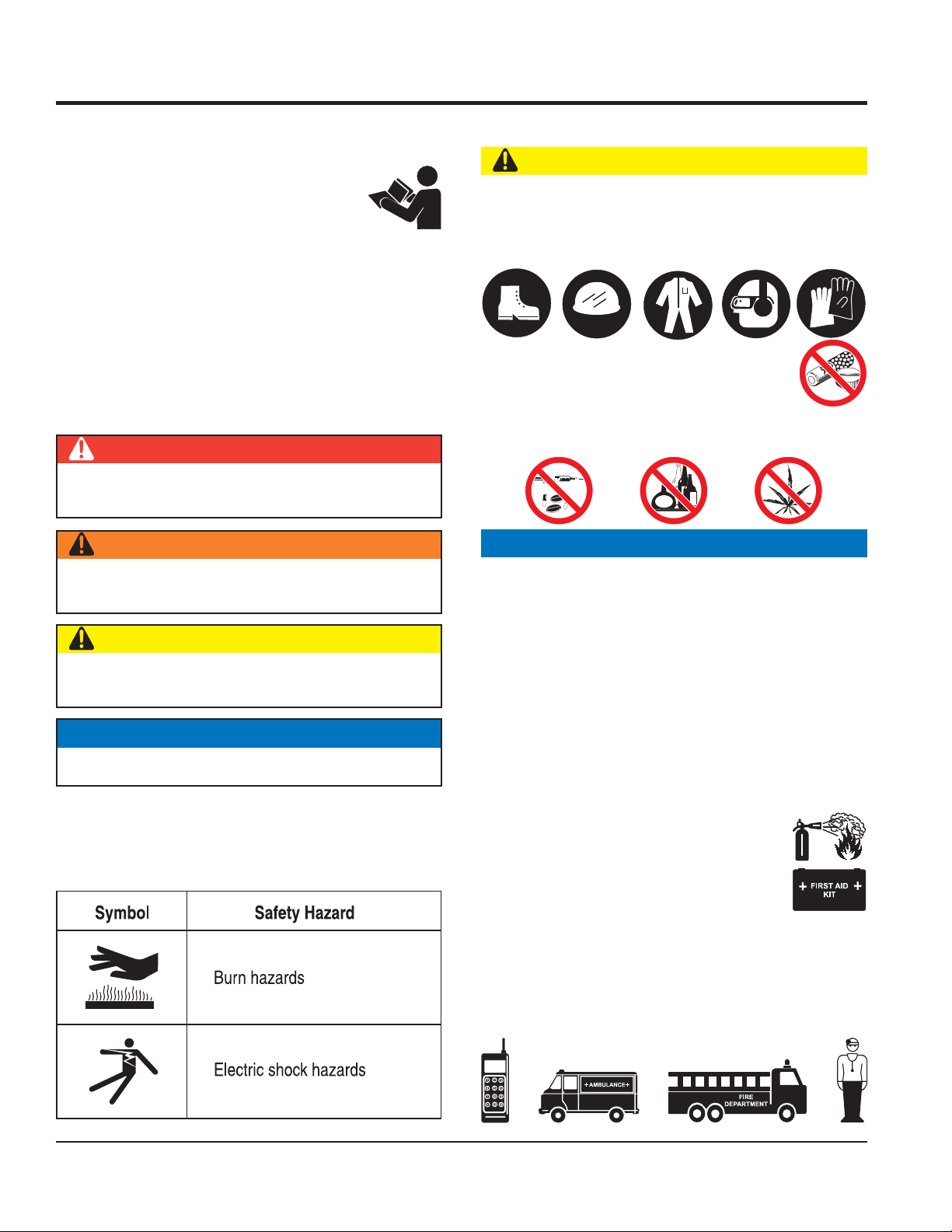
SAFETY SYMBOLS
DANGER
Indicates a hazardous situation which, if not avoided,
WILL result in DEATH or SERIOUS INJURY.
WARNING
GENERAL SAFETY
CAUTION
NEVER operate this equipment without proper protective
clothing, shatterproof glasses, respiratory protection,
hearing protection, steel-toed boots and other protective
devices required by the job or city and state regulations.
NEVER operate this equipment when not
feeling well due to fatigue, illness or when
under medication.
NEVER operate this equipment under the infl uence of
drugs or alcohol.
NOTICE
Indicates a hazardous situation which, if not avoided,
COULD result in DEATH or SERIOUS INJURY.
CAUTION
Indicates a hazardous situation which, if not avoided,
COULD result in MINOR or MODERATE INJURY.
NOTICE
Addresses practices not related to personal injury.
Potential hazards associated with the operation of this
equipment will be referenced with hazard symbols which
may appear throughout this manual in conjunction with
safety messages.
This equipment should only be operated by trained and
qualifi ed personnel 18 years of age and older.
Whenever necessary, replace nameplate, operation and
safety decals when they become diffi cult read.
Manufacturer does not assume responsibility for any
accident due to equipment modifi cations. Unauthorized
equipment modifi cation will void all warranties.
NEVER use accessories or attachments that are not
recommended by Multiquip for this equipment. Damage
to the equipment and/or injury to user may result.
ALWAYS know the location of the nearest
fi re extinguisher.
ALWAYS know the location of the nearest
fi rst aid kit.
ALWAYS know the location of the nearest phone or keep
a phone on the job site. Also, know the phone numbers
of the nearest ambulance, doctor and fi re department.
This information will be invaluable in the case of an
emergency.
PAGE 4 — GB114BS/BP GLOBUG LIGHTING SYSTEM • OPERATION AND PARTS MANUAL — REV. #3 (01/06/09)
Page 5
SAFETY INFORMATION
LIGHTING SYSTEM SAFETY
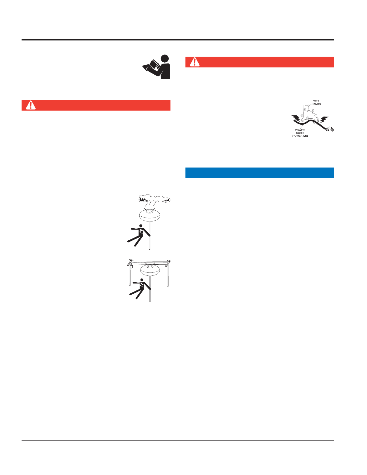
DANGER
NEVER use lighting system in rain, snow or
areas of high humidity that could generate
electrical storms.
WARNING
NEVER disconnect any emergency or safety devices.
These devices are intended for operator safety.
Disconnection of these devices can cause severe injury,
bodily harm or even death. Disconnection of any of
these devices will void all warranties.
CAUTION
NEVER attempt service on a running machine.
NOTICE
To prevent the lighting system from overturning, NEVER
use in winds that exceed 22 mph (10 m/s).
The lighting system should only be used in temperatures
between 23° to 104°F (-5° to 40° C). Failure to comply
with these operating parameters could cause the lamp
to malfunction and shorten the ballast life.
NOTICE
NEVER leave any grease or oil residue on lamp surface
when replacing or removing lamp. This can create hot
spots, reducing the service life of the lamp.
ALWAYS make sure lamp surface is clean and dry.
ALWAYS replace with MQ recommended type lamp. See
parts section of this manual.
If applicable, ALWAYS make sure the lamp guard is
installed correctly. NEVER deform the lamp guard.
NEVER unplug the lamp’s AC power cable during
operation.
ALWAYS have a trained technician to install and
remove lamp or replace any damaged fi xture wiring.
BALLOON SAFETY
WARNING
To prevent serious burns, NEVER touch
or unzip the balloon envelope when the
lamp is on.
CAUTION
ALWAYS keep the lighting system in proper running
condition.
Fix damage to lighting system and replace any broken
parts immediately.
ALWAYS store equipment properly when it is not being
used. Equipment should be stored in a clean, dry location
out of the reach of children and unauthorized personnel.
LAMP SAFETY
WARNING
NEVER attempt to replace lamp with the power on.
Always unplug the power cord from the generator or
power source when changing the lamp.
ALWAYS allow a suffi cient amount of time for the lamp to cool
before changing. The possibility exists of severe burns.
CAUTION
NEVER use force when installing the lamp. Excessive force
could cause the lamp to break, causing bodily harm.
ALWAYS keep the balloon away from sharp objects and
excessive amounts of heat.
NOTICE
To prevent balloon deformation, NEVER use lighting
system in strong winds.
DO NOT place the balloon inside its protective cover
until the lamp has had a suffi cient amount of time to cool
down. This will prevent the balloon’s nylon cover from
being burned (touching the lamp surface).
ALWAYS place the balloon inside its protective cover
after each use. This will prolong the life of the balloon
material, keeping it protected from harsh environmental
elements.
Replace balloon immediately if damaged. A damaged
balloon will not infl ate properly, and may become more
damaged by touching the hot lamp surface.
DO NOT use excessive force when zipping and unzipping
the balloon. Be gentle with the zipper mechanism. If the
zipper is broken, the balloon will become unusable.
GB114BS/BP GLOBUG LIGHTING SYSTEM • OPERATION AND PARTS MANUAL — REV. #3 (01/06/09) — PAGE 5
Page 6
SAFETY INFORMATION
GENERATOR SAFETY
If using a generator to power lighting system,
refer to applicable generator manual safety
information section.
ELECTRICAL SAFETY
DANGER
Lighting system is equipped with a ground pin on the
power plug. For your protection, ALWAYS complete the
grounding path. NEVER insert the AC power plug into a
2-prong receptacle to operate lighting system.
When applying power to the lighting system, ALWAYS
connect the AC power plug to a 3-prong receptacle that
is grounded. The possibility exists of electrical shock,
electrocution and even death if the lighting system is
not grounded.
NEVER operate lighting system or
handle any electrical equipment while
standing in water, while barefoot,
while hands are wet or in the rain. A
dangerous electrical shock could
occur, causing severe bodily harm
or even death.
Power Cord/Cable Safety
DANGER
NEVER let power cords or cables lay in water.
NEVER use damaged or worn cables or cords. Inspect
for cuts in the insulation
NEVER grab or touch a live power
cord or cable with wet hands. The
possibility exists of electrical shock,
electrocution or death.
Make sure power cables are securely connected.
Incorrect connections may cause electrical shock and
damage to the lighting system.
NOTICE
ALWAYS make certain that proper power or extension
cord has been selected for the job. See Cable Selection
Chart in this manual.
ALWAYS make sure the area above
the lighting system is open and clear
of overhead power lines and other
obstructions. Contact with overhead
power lines or other obstructions
could result in equipment damage,
electrical shock, electrocution and
even death.
PAGE 6 — GB114BS/BP GLOBUG LIGHTING SYSTEM • OPERATION AND PARTS MANUAL — REV. #3 (01/06/09)
Page 7
SAFETY INFORMATION
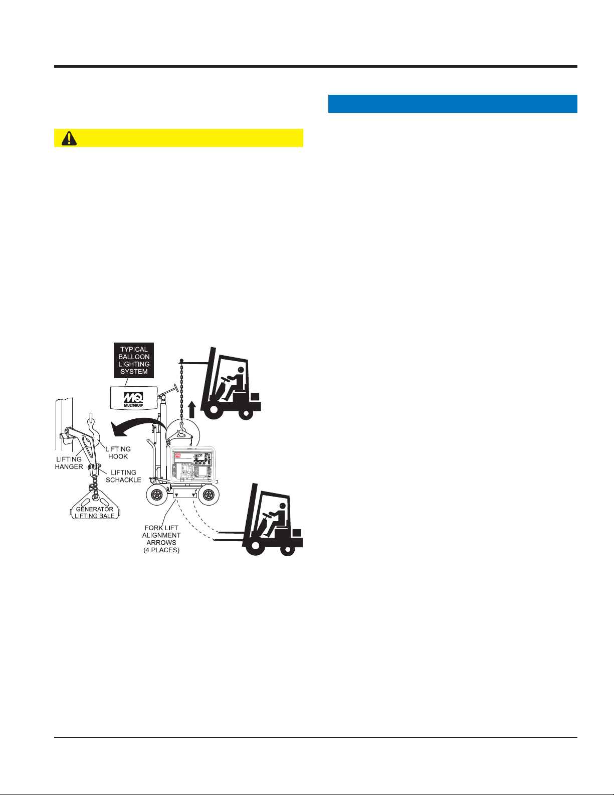
LOADING AND UNLOADING
If lighting system is equipped with a transport lifting hook,
refer to the following safety information.
CAUTION
Before lifting, make sure that lighting system parts are
not damaged and screws are not loosened or lost.
ALWAYS make sure crane or lifting device has been
properly secured to lifting hook of the equipment.
NEVER lift the equipment while lighting system is
running.
Make sure the mast is completely lowered before lifting
the lighting system.
Use adequate lifting cable (wire or rope) of suffi cient
strength.
Use one point suspension hook and lift straight upwards.
TRANSPORTING SAFETY
NOTICE
When transporting the lighting system, if applicable,
always place in stow position and place mast in its
carrying case.
ALWAYS remove balloon/lamp assembly from the mast
when transporting lighting system. This will prevent
damage to the bulb due to vibration.
NEVER leave the balloon/lamp exposed during transport.
Exposure to excess wind or rain could damage the
balloon’s nylon cover.
ALWAYS place balloon inside its protective cover during
transport. Be sure the cover is secured tightly around the
balloon/lamp assembly.
Never allow any person or animal to stand underneath the
equipment while lifting.
DO NOT lift machine to unnecessary heights.
GB114BS/BP GLOBUG LIGHTING SYSTEM • OPERATION AND PARTS MANUAL — REV. #3 (01/06/09) — PAGE 7
Page 8
SPECIFICATIONS
Specifi cationsTable 1.
GloBug Lighting System
Model GB114BS/GB114BP
Input Voltage 120 VAC
Ballast Magnetic Ballast 60 Hz
Frequency 60 Hz Single-Phase
Max. Current 9.5 Amps
Lamp
Lamp Type 1000 Watt Metal Halide
Lumens 112,000
Light Coverage (360°) 150 ft. (45.72 meters)
Surface Temperature (Longitudinal) 476.6°F (247°C) Max.
Surface Temperature (Transversal) 417.2°F (214°C) Max.
Fan Motor
Balloon Fan Motor 115 VAC, 60 Hz
Max. Current .360 Amps
Pressure 31.26 PSI (215.6 kPA)
Balloon
Diameter 47.16 in. (1,200 mm)
Material Heat Resistant Nylon
Heat Resisting Temperature 320 ~ 356°F (160 ~ 180°C)
Melting Temperature 500°F (260°C)
Internal Temperature of Balloon 126°F (52°C) Average
Water Resistance 1,500 mm H20
Weight
GB114BS 83 lb. (38 kg)
GB114BP 61 lb. (28 kg)
PAGE 8 — GB114BS/BP GLOBUG LIGHTING SYSTEM • OPERATION AND PARTS MANUAL — REV. #3 (01/06/09)
Page 9
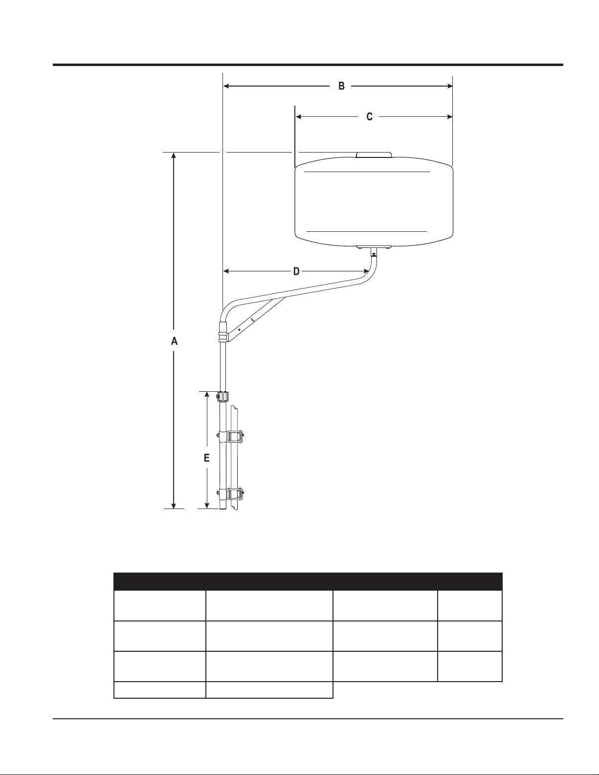
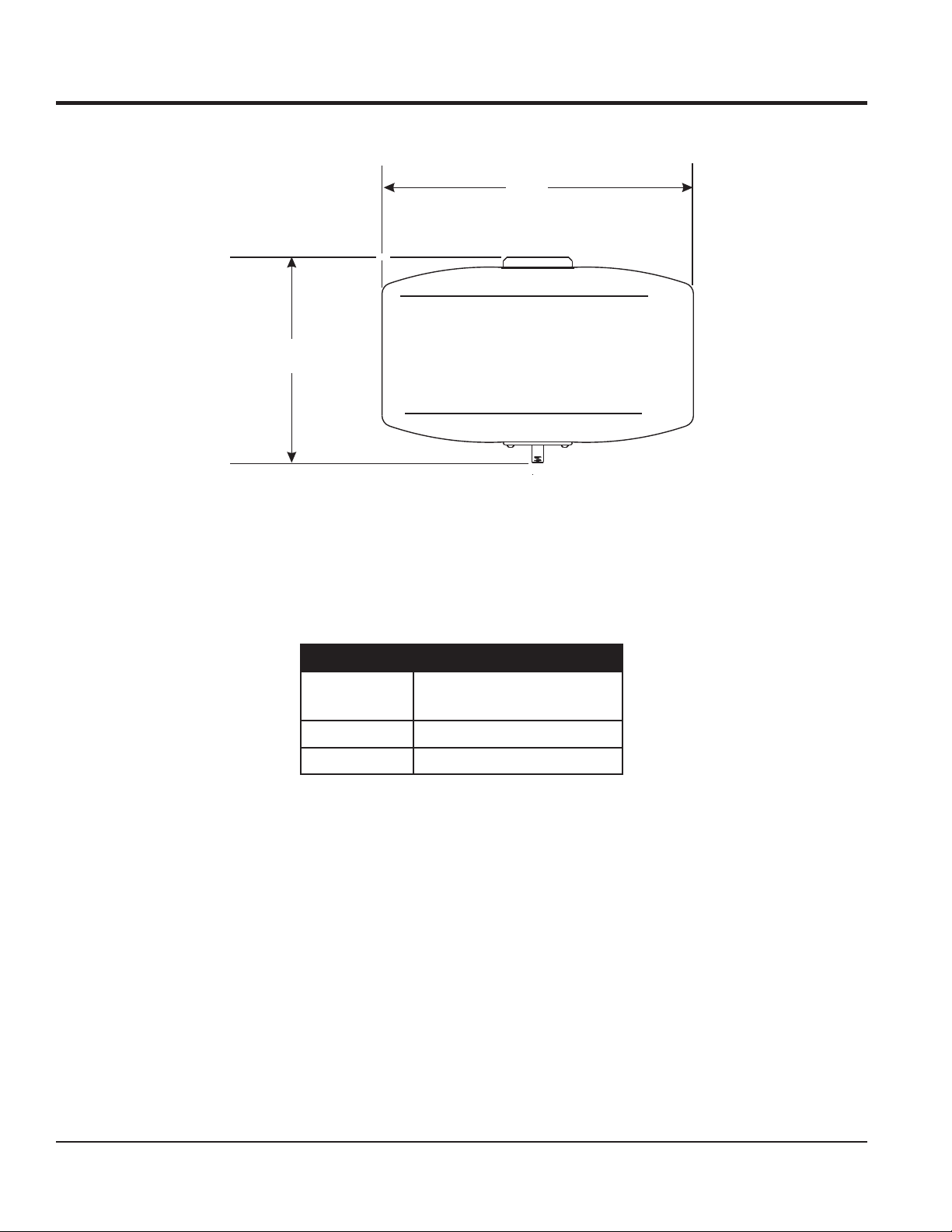
DIMENSIONS (GB114BS)
Dimensions (GB114BS)Figure 1.
DimensionsTable 2.
Reference Letter Dimension in. (mm.) Reference Letter
A
B 59 in. (1,500 mm.) E
C 47.16 in. (1,200 mm.)
GB114BS/BP GLOBUG LIGHTING SYSTEM • OPERATION AND PARTS MANUAL — REV. #3 (01/06/09) — PAGE 9
88.0 -108.0 in.
(2,230 - 2,730 mm.)
D
Dimension
in. (mm.)
35.00 in.
(900 mm.)
35.00 in.
(900 mm.)
Page 10
A
DIMENSIONS (GB114BP)
B
Dimensions (GB114BP)Figure 2.
DimensionsTable 3.
Reference
Letter
A 28.00 in. (712 mm.)
B 47.16 in. (1,200 mm.)
Dimension in. (mm.)
PAGE 10 — GB114BS/BP GLOBUG LIGHTING SYSTEM • OPERATION AND PARTS MANUAL — REV. #3 (01/06/09)
Page 11
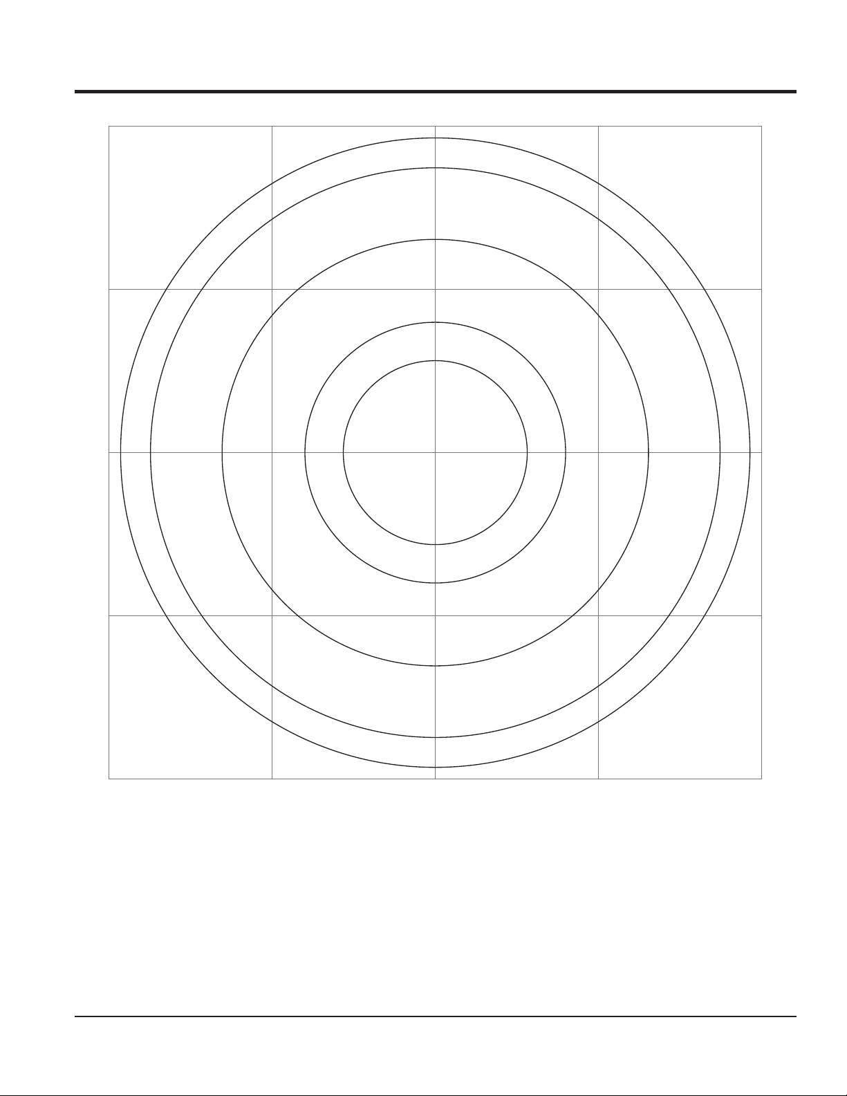
360° Coverage
FOOTCANDLE PLOT
.5
1
2
5
10
Values listed as footcandles
Floodlight Footcandle Plot (BAL-115 Drum Shaped)Figure 3.
GB114BS/BP GLOBUG LIGHTING SYSTEM • OPERATION AND PARTS MANUAL — REV. #3 (01/06/09) — PAGE 11
Scale: Grid = 50 ft. (15.25 meters)
Page 12
GENERAL INFORMATION
The Multiquip GloBug GB114BS, and GB114BP are
general purpose portable glare-free lighting systems.
Typical applications for these types of lighting systems
include construction sites, emergency road crews and
backyard parties.
BALLOON ENVELOPES
The GloBug lighting system can be confi gured with a
variety of balloon envelopes (canopy). Please contact the
MQ sales department for the balloon of your choice. The
GloBug GB114BS and GB114BP shipped from the factory
with the drum type balloon.
LIGHTING
Multiquip's GloBug lighting system is comprised of one
"Metal Halide" 1000-watt lamp. This lamp has an output of
112,000 lumens. Typical lighting coverage is in excess 150
ft. (46 meters) in a 360 degree pattern.
POWER
These GloBug lighting systems are powered by a
portable ballast that can be hand carried. The input power
requirements for operating the lighting system is 120 VAC,
60 Hz @ 9.5 amps
GB114BP
When only a complete lamp assembly is required please
order Model GB114BP. This model number includes the
lamp, protective guard, balloon protective covering and all
other components that make up the lamp assemby.
TRANSPORT
The GB114 lighting systems can be transported quite easily.
The GB114BP consists of a balloon/lamp, power cable
and a ballast, and it has a combined weight of 61 lbs (28
kg). The GB114BS consists a balloon/lamp, power cable,
ballast and offset pole, and it has a combined weight of
83 lbs (38 kg).
For ease of service or transport, the lamp assembly is
equipped with a quick-disconnect connector that allows
the lamp fi xture to be removed quickly. This feature is
extremely useful during transport of the lighting system. It
is always best to remove the lamp and pack it safely so it
will not be damaged.
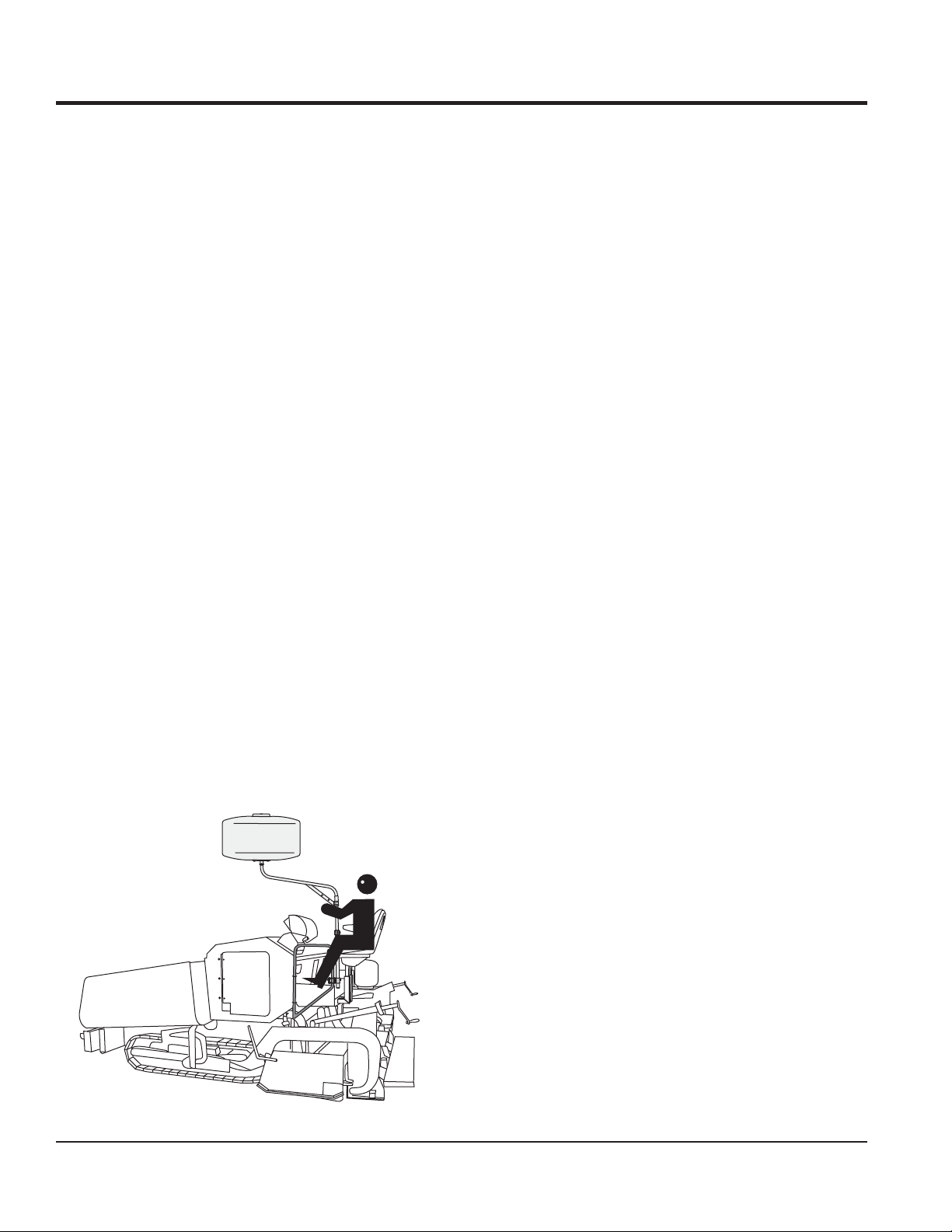
GB114BS
The GB114BS lighting system (offset pole) is designed to
be attached to a external piece of a equipment such as a
paver (Figure 4). This system is equally easy to assemble.
Simply attach the supplied support clamps to an external
pole or support and you are ready.
GB114BS Offset Pole (Paver)Figure 4.
PAGE 12 — GB114BS/BP GLOBUG LIGHTING SYSTEM • OPERATION AND PARTS MANUAL — REV. #3 (01/06/09)
Page 13

NOTES
GB114BS/BP GLOBUG LIGHTING SYSTEM • OPERATION AND PARTS MANUAL — REV. #3 (01/06/09) — PAGE 13
Page 14
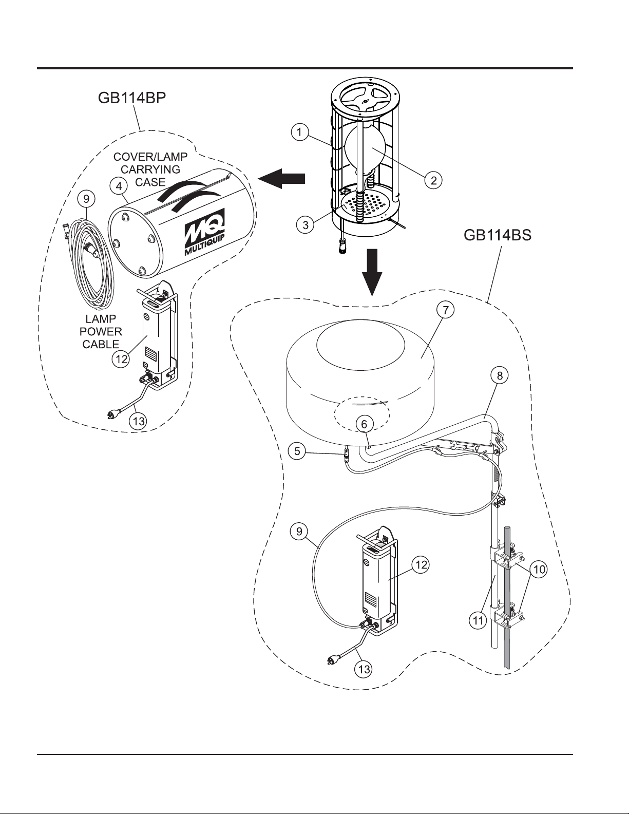
COMPONENTS
Major ComponentsFigure 5.
PAGE 14 — GB114BS/BP GLOBUG LIGHTING SYSTEM • OPERATION AND PARTS MANUAL — REV. #3 (01/06/09)
Page 15

COMPONENTS
Figure 5 shows the location of the components for the
GloBug lighting system. The function of each component
is described below:
Lamp Guard 1. — This guard (cage) protects the lamp
from being hit by objects.
Lamp 2. — 1000 watt metal-halide type lamp. Replace
only with MQ recommended type lamp. Always allow
a suffi cient amount of time for the lamp to cool down
before changing.
Fan Motor (Blower) 3. — This electric motor is
responsible for infl ating the balloon. It will supply a
pressure of 31.26 psi /215.6 kPA. Please note that the
balloon will begin to infl ate as soon as power is applied
to the lighting system.
Balloon Cover/Carrying Case 4. — When zipped, this
protective cover acts like a carrying case. The complete
lamp assembly is enclosed within the cover-carrying
case. Allow a suffi cient amount of time for the lamp
to cool down before covering balloon. The possibility
exists of the balloon getting burned.
Lamp Assembly Connector 5. — Quick-disconnect
cable. Provides AC power to lamp assembly.
T-Handle Bolt Lock 6. — Always tighten this lock to hold
the lamp/balloon securely in place.
Balloon 7. — This balloon is made of heat-resistant
nylon, with a diameter of 47 inches (1200 mm).
Offset Pole 8. — Supports lamp assembly when attached
to the main mast. Included with the offset pole is a
17/19 mm wrench.
Lamp Power Cable (Output) 9. — Connect this cable
between the ballast receptacle and the lamp assembly
connector.
Pole Clamps 10. — Attach these clamps (2) to the
main pole and external support pole. Always tighten
both clamps securely to prevent slippage of the light
assembly.
Main Pole 11. — Used in conjunction with the offset pole
to support the lamp assembly.
Ballast 12. — Power source for lamp. Input power
requirements are 120 VAC, 60 Hz @9.5 amps.
Ballast AC Power Cable (Input) 13. — Connect this cable
to a 120 VAC, 60 Hz power source.
GB114BS/BP GLOBUG LIGHTING SYSTEM • OPERATION AND PARTS MANUAL — REV. #3 (01/06/09) — PAGE 15
Page 16

SETUP
M
M
NOTICE
The pole clamp assembly used in this setup procedure
is a dual type clamp. One side of the clamp is for the
attachment of the main pole of the lighting system. The
other side of the clamp is used for the attachment of
a support pole that is usually connected to a piece of
equipment such as a paver.
POLE SETUP
Refer to Figure 6 for the following procedure.
Remove the offset pole (B) from the shipping 1.
container.
Attached to the offset pole is a 17/19 mm open-end 2.
wrench (C). Remove the wingnut (D) securing the
wrench to the offset pole and remove wrench.
Reinsert wingnut and washer back into offset pole so 3.
they will not get lost or misplaced.
Remove the two pole clamp assemblies (A) from the 4.
shipping container. Attach one pole clamp assembly
(E) to the main pole (F) about 3 inches (76.2 mm) down
from the main pole extension clamp. Using supplied
19 mm wrench, tighten locknut on the pole clamp
assembly securely.
Attach the other pole clamp assembly (G) to the main 5.
pole (F) about 7.0 in. (140 mm.) down from the previous
attached pole clamp assembly (E). Using the 19 mm
wrench, tighten locknut on the pole clamp assembly
securely.
To attach main pole (F) to equipment support pole (I), 6.
swing open adjustable tension plate (H) on clamp so
that it can accomodate the diameter of the equipment
support pole. Insert equipment support pole (I) through
the two equipment support pole clamp assemblies as
shown in Figure 6.
Once the equipment support pole (I) has been seated 7.
properly, move adjustment bolt and locknut (J) into
locking position. Use the supplied 17 mm wrench, to
tighten locknuts (J) on both clamps securely.
Using 17 mm wrench, tighten both bolts (M) on the 9.
offset adapter clamp (K) securely.
Place lamp assembly (N) onto offset pole (B). Tighten 10.
T-handle bolt (O) securely.
T-HANDLE
LOCKNUT
MAIN POLE
CLAMP
POLE
CLAMP
ASSEMBLY
A
P
EQUIPMENT
SUPPORT
POLE CLAMP
ADJUSTABLE
CHANNEL
REMOVE
WRENCH
ADJUSTMENT
BOLT AND
LOCKNUT
H
TENSION
PLATE
Offset Pole AssemblyFigure 6.
J
EQUIPMENT
BALLOON
POWER
CABLE
N
LAMP
ASSEMBLY
O
WINGNUT
D
CLAMP
MAIN
POLE
CLAMP
SUPPORT
POLE
I
C
E
POLE
ASSY.
F
G
POLE
ASSY.
B
OFFSET
POLE
K
OFFSET
ADAPTER
CLAMP
M
L
ADJUSTABLE
EXTENSION
POLE
EXTENSION
CLAMP
BOLT
3.0 IN.
(76.2 M
7.0 IN.
(140 M
Q
Place offset pole (B) with adapter clamp (K) on top of 8.
adjustable extension pole (L). Make sure that offset
pole has been seated correctly.
PAGE 16 — GB114BS/BP GLOBUG LIGHTING SYSTEM • OPERATION AND PARTS MANUAL — REV. #3 (01/06/09)
Page 17

SETUP
REMOVING THE PROTECTIVE COVERING
Expose the balloon by pulling down on the velcro tab 1.
and unzip the protective cover as shown in Figure 7.
STEP 1
UNZIP
PROTECTIVE
COVER
BALOON
STEP 2
FOLD PROTECTIVE
COVER INTO ITSELF
BALLOON
FULLY
EXPOSED
VELCRO
TAB
PROTECTIVE
COVER
CONNECTING POWER CABLE
Connect 16.4 ft. (5 meters) lamp power cable (Figure 8) 1.
to the balloon power cable.
BALLOON
POWER
CABLE
BALLAST
LAMP
POWER
CABLE
LAMP
ASSEMBLY
Connecting Lamp Power CableFigure 8.
Attach both S-type hooks (Figure 9) on the lamp power 2.
cable into the cable support holes on the offset pole.
OFFSET
Folding Protective CoverFigure 7.
LAMP
POWER
CABLE
S-TYPE
HOOK
Attachment of S-HooksFigure 9.
POLE
GB114BS/BP GLOBUG LIGHTING SYSTEM • OPERATION AND PARTS MANUAL — REV. #3 (01/06/09) — PAGE 17
Page 18

OPERATION
RAISING THE EXTENSION POLE
Before raising the extension pole, make sure the 1.
T-handle bolt lock (Figure 6-O) is securely tightened.
This will prevent the balloon/lamp assembly from falling
off. In addition make sure that the lamp power cable
is connected to the mating end of the power source
cable.
Raise extension pole (Figure 6-L) to desired height. 2.
Watch out for any overhead obstructions.
Using 19 mm wrench, tighten extension clamp bolt 3.
(Figure 6-Q) securely. Keep wrench in a safe place
where it will not get lost.
DANGER
ALWAYS make sure the area
above the lighting system is
open and clear of overhead
power lines and other
obstructions. Contact with
overhead power lines or other
obstructions could result in
equipment damage, Serious
Injury or Death!
APPLYING POWER
Make sure the power ON/OFF switch (Figure 10) 1.
located near the bottom of the ballast is in the OFF
position.
ON/OFF
SWITCH
BALLAST
OFF
Power OFF/ON Switch (Off Positon)Figure 10.
If using a power source (Figure 11) other than a 2.
portable generator, plug the AC power cord from the
ballast into a 120 VAC, 60 Hz receptacle that is
protected by a at least a 15 amp circuit breaker.
CONNECT
TO BALLOON
POWER
CABLE
BALLAST
DANGER
When raising the extension pole, ALWAYS
be on the lookout for overhead obstructions
such as high voltage power lines. The
possibility exists of electrocution, even
death! if the lighting system comes in
contact with high voltage power lines.
EXTERNAL
SINGLE-PHASE
(120 VAC)
POWER SOURCE
AC POWER
CORD
RECEPTACLE
Applying 120 VAC PowerFigure 11.
NOTICE
If using a portable generator, start the generator as
referenced in the "Start-up Section" of the supplied
generator manual.
Once the generator has started, plug the AC power cord
from the ballast (Figure 11) into a GFCI receptacle on
the generator.
PAGE 18 — GB114BS/BP GLOBUG LIGHTING SYSTEM • OPERATION AND PARTS MANUAL — REV. #3 (01/06/09)
Page 19

OPERATION/SHUTDOWN
NOTICE
ALWAYS Make sure ballast is securely mounted to
a surface where it will not move, slip or fall. This will
prevent severe damage to the ballast.
Place the ON/OFF switch (Figure 12) on the ballast in 3.
the ON position.
ON/OFF
SWITCH
BALLAST
ON
Ballast On/Off Switch (On Position)Figure 12.
Notice that the balloon envelope will begin to deploy 4.
as soon as power is applied.
SHUTDOWN
Place the ON/OFF switch on the ballast to the OFF 1.
position. The balloon should begin to defl ate and the
lamp turns off.
If using a portable generator, shut-down the generator 2.
as referenced in the "Shutdown Section" of the supplied
generator manual. ALWAYS place the main circuit
breaker in the OFF position before turning off the
generator.
If using a power source other than an AC generator, 3.
disconnect the ballast AC power cable from the power
source.
The lamp should now be on. If the lamp is not on, 5.
check all connections and repeat steps 1 thru 4. If the
lamp still does not come on, contact your nearest MQ
service center.
The lighting system is now ready for use.6.
GB114BS/BP GLOBUG LIGHTING SYSTEM • OPERATION AND PARTS MANUAL — REV. #3 (01/06/09) — PAGE 19
Page 20

Y
STORAGE
NOTICE
Allow a suffi cient amount of time (15-20 minutes) for the
lamp to cool down . The possibility exists of the balloon
getting burned (touching the lamp).
LOWERING THE EXTENSION POLE
Using the supplied 19 mm wrench, loosen extension 1.
clamp bolt (Figure 6-Q).
Carefully pull down on the adjustable extension pole 2.
(Figure 6-L) and lower lamp assembly.
Remove wingnut (Figure 6-D) from offset pole (Figure 3.
6B) and insert wrench into wrench holder. Reinsert
wingnut and tighten.
REMOVING LAMP ASSEMBLY
Disconnect balloon power cable (Figure 13) from the 1.
lamp power cable. Place lamp power cable in a safe
place where it will not get damage or lost..
Remove both S-type hooks (Figure 9) on the lamp 2.
power cable from the cable support holes on the offset
pole.
Unzip the zipper on the protective cover (Figure 14), 3.
and pull down cover over balloon/lamp assembly.
ZIPPER
PROTECTIVE
COVER
Unzipping the Protective CoverFigure 14.
Fully zip protective cover and fold velcro tab in place.4.
PROTECTIVE
COVER
BALLOON
POWER
CABLE
LAMP
POWER
CABLE
LAMP
ASSEMBL
VELCRO
TAB
Zipping the Protective CoverFigure 15.
Loosen T-handle bolt (Figure 6-O) by turning 5.
counterclockwise and remove lamp assembly (Figure
6-N) from offset pole.
Store lamp assembly enclosed within its protective 6.
cover (Figure 16) in a safe location where it will not be
damaged.
Disconnecting Power CablesFigure 13.
COVER/LAMP
CARRYING
CASE
Storing Lamp AssemblyFigure 16.
PAGE 20 — GB114BS/BP GLOBUG LIGHTING SYSTEM • OPERATION AND PARTS MANUAL — REV. #3 (01/06/09)
Page 21

MAINTENANCE
CAUTION
Before performing any maintenance
procedures, be sure to READ the lamp,
balloon, and general safety guidelines
in this manual. Failure to read and
understand these safety guidelines could
cause severe equipment damage and
bodily harm.
REMOVING THE LAMP ASSEMBLY
Allow lamp (Figure 17) 15-20 minutes to cool before 1.
changing.
CAUTION
DO NOT use excessive force when zipping
or unzipping the balloon. The possibility
exists of the zipper tearing, which would
make the balloon unusable.
REMOVING THE BALLOON
Expose the balloon (Figure 19) by pulling down on the 1.
velcro tabs and unzip the protective cover as shown in
Figure 7. Next, fold the protective cover into itself and
zip
ZIPPER
(BOTTOM)
BALLOON
ZIPPER
(TOP)
DO NOT USE
EXCESSIVE FORCE
WHEN ZIPPING OR
UN ZIPPING THE
BALLOON
PROTECTIVE
COVER
(FOLDED)
Figure 17.
Hot Lamp Surface
If lamp assembly is attached to offset pole, loosen 2.
T-handle knob (Figure 18) that secures the lamp to the
offset pole.
LAMP
ASSEMBLY
T-HANDLE
KNOB
Figure 18.
T-Handle Knob
Lift lamp assebly from offset pole, and place on a 3.
suitable work bench that is free of dirt, and sharp
objects that could damage the balloon.
Figure 19.
Exposing the Balloon
Unzip the zipper (Figure 19) at the bottom of the balloon 2.
and roll the balloon envelope upwards to expose the
lamp (Figure 20). Remove the lamp guard to gain
access to the lamp. DO NOT use excessive force when
unzipping the balloon.
LAMP GUARD
PIPE FRAME
TO REMOVE
LAMP GUARD
LIFT UPWARDS
FROM PIPE FRAME
BALLOON
Removing the Lamp GuardFigure 20.
GB114BS/BP GLOBUG LIGHTING SYSTEM • OPERATION AND PARTS MANUAL — REV. #3 (01/06/09) — PAGE 21
Page 22

MAINTENANCE
Push down and hold the lamp holder (spring loaded) 3.
away from the lamp (Figure 21). Unscrew the lamp
(turn counterclockwise) from the lamp socket.
LAMP
SOCKET
LAMP
HOLDER
PUSH
DOWN
TO REMOVE LAMP
TURN COUNTER-
CLOCKWISE
Removing the LampFigure 21.
INSTALLING A NEW LAMP
When installing a new lamp (Figure 22) use only 1.
MQ recommended type lamp. See parts section of
this manual. Failure to use correct type lamp could
adversely affect lighting capability and may cause
damage to the equipment.
Push down and hold the lamp holder (spring loaded) 2.
away from the lamp. Screw the lamp (turn clockwise)
into the lamp socket. Gently place the lamp holder
fi rmly over the top of the lamp. This will prevent the
lamp from touching the lamp guard or pipe frame.
BALLOON
PIPE FRAME
SNAP LAMP
GUARD INTO
PIPE FRAME
Installing the Lamp GuardFigure 23.
Zip up the zipper at the bottom (Figure 19) of the 2.
balloon and pull down the balloon envelope to cover
the lamp
Place the lamp/balloon assembly back onto the mast.3.
Tighten the T-Handle Bolt Lock to secure the lamp to 4.
the mast.
Reinstall the protective cover over the balloon/lamp 5.
assembly. Be sure to fold the velcro tabs.
Reconnect the power cables.6.
REPLACING THE BALLOON
Follow the procedures as outlined in the "Removing 1.
the Balloon Lamp" assembly section.
Unzip the zipper at the bottom and top of the balloon. 2.
Slide the balloon over the top of the lamp guard as
shown in Figure 24.
LAMP
SOCKET
LAMP
HOLDER
(SPRING-LOADED)
LAMP
GUARD
BALLOON
Removing the BalloonFigure 24.
TO INSTALL LAMP
TURN CLOCKWISE
PLACE
LAMP HOLDER
FIRMLY ONTO
LAMP TOP
Slide the new balloon over the top of the lamp guard 3.
as shown in Figure 25. Zip up the zipper at the bottom
and top of the balloon.
Installing the LampFigure 22.
RE-INSTALLING THE LAMP/BALLOON
ASSEMBLY
Reinstall the lamp guard (Figure 23). Be careful not to 1.
install the lamp guard in the wrong direction.
PAGE 22 — GB114BS/BP GLOBUG LIGHTING SYSTEM • OPERATION AND PARTS MANUAL — REV. #3 (01/06/09)
LAMP
GUARD
BALLOON
Removing the BalloonFigure 25.
Page 23

MAINTENANCE
CAUTION
DO NOT replace fi lter immediately, allow
a suffi cient amount of time for the lamp
assembly to cool down before changing
fi lter
FILTER REPLACEMENT
Remove the balloon as described in the "Removing 1.
the Lamp/Balloon" section.
Disconnect the lamp power cable (Figure 5).2.
Rotate the balloon/lamp base assembly so that the 3.
fi lter is facing upwards. See Figure 26.
BALLOON/LAMP
Install a new fi lter over the brace as shown in Figure 5.
28. Be sure to align the cut of the fi lter over the brace.
BRACE
FILTER
CUT
Figure 28.
Filter Placement
CAUTION
When placing the fi lter element, always align the cut
of the fi lter on top of the brace. This will keep the fi lter
from being dislodged and getting damaged.
Balloon/Lamp PlacementFigure 26.
Turn the three locking tabs (Figure 27) inward to 4.
release the plate. Remove plate and fi lter.
PLATE
FILTER
TURN
OUTWARD
LOCKING
TAB
Figure 27.
Filter Removal
TO RELEASE
Turn the three retaining tabs (Figure 29) outward so 6.
that they touch the lamp base.
PLATE
FILTER
LOCKING
TAB
Figure 29.
Filter/Plate Install
TURN
INWARD
TO LOCK
GB114BS/BP GLOBUG LIGHTING SYSTEM • OPERATION AND PARTS MANUAL — REV. #3 (01/06/09) — PAGE 23
Page 24

B2
MAINTENANCE
B1
P5
P6
L5
B3
L2
B4
E1
L1
L4
L3
P4
P3
P1
E3
P2
E2
Maintenance Check PointsFigure 30.
PAGE 24 — GB114BS/BP GLOBUG LIGHTING SYSTEM • OPERATION AND PARTS MANUAL — REV. #3 (01/06/09)
Page 25

For a prolonged life cycle an extended quality follow the
recommended GloBug lighting system service guidelines
as referenced in Figure 30 and Table 4.
Periodic Check and MaintenanceTable 4.
Figure Part Check Item Solution Frequency
MAINTENANCE
Lamp
Balloon
Electric
Pole
L1 Lamp (Base) Lamp base loose? Screw in securely
L2 Connector Cable disconnected or loose? Connect securely
L3 Lamp Holder Lamp holder loose? Replace
L4 Pipe Frame Frame pipe skewed? Replace
L5 Lamp Defective lamp? Replace
B1 Balloon (Envelope) Defective or dirty? Replace
B2 Zipper Broken? Replace
B3 Fan Motor (Blower) Not working properly? Repair or replace
B4 T-Handle bolt (Balloon) Broken? Replace
E1 Power Cable Defective or worn cable? Replace
E2 Plug Damaged? Replace
E3 Lamp Switch Damaged or not working properly? Replace
P1 Clamp Broken? Repalce
P2 Support pipe Support pipe bent or damaged? Replace
P3 Support bolt Support bolt loose? Tighten securely
P4 Straight pole Straight pole bent or damaged? Repalce
P5 Offset pole Offset pole bent or damaged? Replace
❖
❖
❖
❖
■
❖
❖
❖
❖
❖
❖
❖
❖
❖
❖
❖
❖
P6 Offselt bolt Offset bolt loose? Tighten securely
❖ - Daily Check ■ - Every 20 Hours
GB114BS/BP GLOBUG LIGHTING SYSTEM • OPERATION AND PARTS MANUAL — REV. #3 (01/06/09) — PAGE 25
❖
Page 26

TROUBLESHOOTING (LAMP)
Practically all breakdowns can be prevented by proper handling and maintenance inspections, but in the event of a breakdown,
please take a remedial action following the diagnosis based on the Lamp Troubleshooting (Table 5) information shown below.
If the problem cannot be remedied, please leave the unit just as it is and consult or company's service department.
Lamp TroubleshootingTable 5.
Symptom Possible Problem Solution
Is AC power turned on? Turn on AC power
Is AC power cable connected? Connect AC power cable.
Is lamp power cable connected? Connect lamp power cable.
Is lamp power cable defective? Replace lamp powe cable.
Is ballast ON/OFF switch turned on? Place switch in the ON position.
Is lamp loose? Screw lamp securely into socket.
Is lamp lit? Replace lamp.
Lamp does not light
Is model of lamp compatible? Use genuine MQ lamp.
Lamp only lights for a
short time.
Balloon does not
infl ate.
Is output voltage at ballast correct?
Are any other electric appliances (other
than light tower) plugged into power
source?
Is lamp not cool enough to light again?
(Interval of 20 to 30 minutes is required
before turning on lamp again)
Is ambient temperature too high (more
than 104 °F (40 °C)?
Is fan motor (blower) not working properly? Check or repair fan motor (blower).
Is balloon envelope defective? Repair or replace balloon envelope.
No-load voltage is between 380~456 VAC. If
voltage is low check 22 µF capacitor.
Unplug all other appliances.
Wait for lamp to cool down
Move lamp where there is proper ventilation.
PAGE 26 — GB114BS/BP GLOBUG LIGHTING SYSTEM • OPERATION AND PARTS MANUAL — REV. #3 (01/06/09)
Page 27

WIRING DIAGRAM
GRN
P1
BLK (LINE)
CHASSIS
GND
SPLICE
BLK
GRN
GRN
BLK
J1
2
4
120 VAC, 60Hz
INPUT BALLAST
POWER CABLE
WHT (NEUTRAL)
S1
OFF/ON
SWITCH
BLK
FRONT VIEW
BALLAST
RECEPTACE
(FEMALE)
1
WHT
RED
3
MALE
NOT USED
RED
ORANGE
PURPLE
BLACK
24uF
@480 VDC
CAPACITOR
C1
208 VAC
240 VAC
277 VAC
TRANSFORMER
(BALLAST)
RED/BLK YEL YEL
RED
METAL HALIDE
T1
120 VACCOMCAP
BLK/YEL
BLK
1000 WATT
LAMP
LAMP
POWER
CABLE
FEMALE
FRONT VIEW
LAMP CABLE
MALE PLUG
(W1)
RED
WHT
GRN
GND
RED (HOT)
WHT (NEUTRAL)
BUZZER
B1
DS1
S2
S3
MICRO-SWITCH
WITH SENSOR
WHT
WHT
RED
WHT
2
1
3
4
P2
REF.
DESC.
P1
Input Power Cable Assy.(Ballast) A300066700
Ballast Output Receptacle
J1
Lamp Fan Cable Assy. (Input)
P2
DS1
1000 Watt Metal Halide Lamp E000009800
24 uf Capacitor @ 480 VDC 19598
C1
Ballast (Transformer) A300033800
T1
GRN
BLK
16 AWG.
DESCRIPTION
BLK
BLK
TABLE 6. REFERENCE DESIGNATIONS
PART NUMBER
A400079400
A300105500
REF.
DESC.
M1
B1
S1
S2
S3
W1
BLUE
MOTOR
BLK
DESCRIPTION
Fan Motor Assy. A300033500
Buzzer Alarm Balloon E000030100
ON/OFF Switch A400037502
Micro-Switch 1400150210
Micro-Switch Cap 1400150410
Lamp Power Cable A300083600
PART NUMBER
FAN
M1
Electrical Wiring DiagramFigure 31.
GB114BS/BP GLOBUG LIGHTING SYSTEM • OPERATION AND PARTS MANUAL — REV. #3 (01/06/09) — PAGE 27
Page 28

VOLTAGE MEASUREMENTS
DANGER
Be careful when performing voltage measurements.
The possiblity exists of electrical shock if fi ngers make
contact with connector pins, thus causing bodily harm
or even death.
NEVER allow multimeter test leads to make contact
with each other. The possibility exists of electrical short
causing severe damage to the equipment, bodily
harm, electrocution, and even death!
VOLTAGE MEASUREMENT (BALLAST NO-LOAD)
Remove lamp from pipe frame as refrenced in 1.
maintenance section of this manual.
Place lamp in a safe place where it will not get damaged 2.
or broken.
Apply 120 VAC power to the ballast. Place ballast ON/3.
OFF switch in the ON position.
Using a multimeter (Figure 32) measure the output 4.
voltage at the ballast receptacle. Pins 1-3 (lamp) should
read between 380~465 VAC. Pins 1-2 (fan motor)
should read 120 VAC.
VOLTAGE MEASUREMENT (LAMP SOCKET NOLOAD)
Connect the female end of the lamp power cable to 1.
the male power connector that is attached to the lamp
assembly.
Place ballast ON/OFF switch in the ON position.2.
Using a multimeter, place one test lead on the lamp 3.
socket tab, place the other lead on the threaded portion
of the socket.
A voltage between 380~465 VAC should be present 4.
between lamp socket tab and threaded portion of the
lamp socket. If the voltage is not present, check wiring
inside pipe frame and lamp socket.
Place the ballast ON/OFF switch in the OFF position.5.
VOLTAGE MEASUREMENT (FAN MOTOR)
Make sure the lamp power cable is securely connected 1.
between the ballast receptacle and the lamp assembly
power connector.
Place the ballast ON/OFF switch in the OFF position. It 2.
is not required for the fan motor test measurement.
Place the ballast ON/OFF switch in the OFF position.5.
VOLTAGE MEASUREMENT (LAMP CABLE NOLOAD)
Connect the male end of the lamp power cable to the 1.
ballast female receptacle.
Place ballast ON/OFF switch in the ON position.2.
Using a multimeter measure the output voltage at the 3.
female end of the of the lamp power cable. Pins 1-3
(lamp) should read between 380~465 VAC. Pins 1-2
(fan motor) should read 120 VAC.
If voltage is not present, replace lamp power cable. 4.
Make sure connection at ballast end of cable is tight
and secure (locked).
Place the ballast ON/OFF switch in the OFF position5.
Apply 120 VAC power to the ballast and listen for the 3.
whirring sound of the fan motor. This sound will indicate
that the fan motor is running.
If the fan motor is not running, use a multimeter and 4.
place one test lead on the black wire and the other lead
on the blue wire as shown in Figure 32.
NOTICE
You may have to use test leads that can prick the wire
insulation. The voltage measured should be 120 VAC.
If 120 VAC is not present check wiring inside pipe
frame.
Additional voltage check can me made at the fan motor 5.
capacitor. Place the multimeter test leads across the
tabs on the capacitor. A voltage of approximately 208
VAC should be measured. If 208 VAC is not present
check or replace capacitor.
PAGE 28 — GB114BS/BP GLOBUG LIGHTING SYSTEM • OPERATION AND PARTS MANUAL — REV. #3 (01/06/09)
Page 29

VOLTAGE MEASUREMENTS
Voltage MeasurementsFigure 32.
GB114BS/BP GLOBUG LIGHTING SYSTEM • OPERATION AND PARTS MANUAL — REV. #3 (01/06/09) — PAGE 29
Page 30

EXPLANATION OF CODE IN REMARKS COLUMN
The following section explains the different symbols and
remarks used in the Parts section of this manual. Use the help
numbers found on the back page of the manual if there are any
questions.
The contents and part numbers listed in the parts section are
subject to change
guarantee the availability of the parts listed.
Sample Parts List:
NO. PART NO. PART NAME QTY. REMARKS
1 12345 BOLT ...................... 1 ......INCLUDES ITEMS W/
2
*
2*12347 WASHER, 3/8 IN. ... 1 ......
3 12348 HOSE ................... A/R .... MAKE LOCALLY
4 12349 BEARING ............... 1 ...... S/N 2345B AND ABOVE
NO. Column
Unique Symbols - All items with same unique symbol
(*, #, +, %, or >) in the number column belong to the same
assembly or kit, which is indicated by a note in the “Remarks”
column.
Duplicate Item Numbers - Duplicate numbers indicate
multiple part numbers are in effect for the same general
item, such as different size saw blade guards in use or a
part that has been updated on newer versions of the same
machine.
When ordering a part that has more than one
item number listed, check the remarks column
for help in determining the proper part to order.
without notice
WASHER, 1/4 IN. .............
. Multiquip does not
NOT SOLD SEPARATELY
MQ-45T ONLY
*
QTY. Column
Numbers Used - Item quantity can be indicated by a
number, a blank entry, or A/R.
A/R (As Required) is generally used for hoses or other parts
that are sold in bulk and cut to length.
A blank entry generally indicates that the item is not sold
separately. Other entries will be clarified in the “Remarks”
Column.
REMARKS Column
Some of the most common notes found in the “Remarks”
Column are listed below. Other additional notes needed to
describe the item can also be shown.
Assembly/Kit
unique symbol will be included when this item is purchased.
Indicated by:
“INCLUDES ITEMS W/(unique symbol)”
Serial Number Break
number range where a particular part is used.
Indicated by:
“S/N XXXXX AND BELOW”
“S/N XXXX AND ABOVE”
“S/N XXXX TO S/N XXX”
Specific Model Number Use
used only with the specific model number or model number
variant listed. It can also be used to show a part is NOT
used on a specific model or model number variant.
Indicated by:
“XXXXX ONLY”
“NOT USED ON XXXX”
- All items on the parts list with the same
- Used to list an effective serial
- Indicates that the part is
PART NO. Column
Numbers Used - Part numbers can be indicated by a
number, a blank entry, or TBD.
TBD (To Be Determined) is generally used to show a part
that has not been assigned a formal part number at time of
publication.
A blank entry generally indicates that the item is not sold
separately or is not sold by Multiquip. Other entries will be
clarified in the “Remarks” Column.
“Make/Obtain Locally”
purchased at any hardware shop or made out of available
items. Examples include battery cables, shims, and certain
washers and nuts.
“Not Sold Separately”
purchased as a separate item and is either part of an
assembly/kit that can be purchased, or is not available for
sale through Multiquip.
- Indicates that the part can be
- Indicates that an item cannot be
PAGE 30 — GB114BS/BP GLOBUG LIGHTING SYSTEM • OPERATION AND PARTS MANUAL — REV. #3 (01/06/09)
Page 31

GB114BP/BS GLOBUG LIGHTING SYSTEM
1 to 3 units
QTY. P/N DESCRIPTION
2............LB41827 ............... LAMP
2............A300033800 ......... BALLAST
2............A300038400 ......... CAPACITOR 22 µF @ 480 VDC
2............1654000230 ..........BALLOON PATCH KIT
SUGGESTED SPARE PARTS
GB114BS/BP GLOBUG LIGHTING SYSTEM • OPERATION AND PARTS MANUAL — REV. #3 (01/06/09) — PAGE 31
Page 32

DANGER
To avoid accident or injury
NEVER exceed a travel
speed of 5 MPH when using
lighting system on a mobile
equipment.
DCL 1001
NAMEPLATE AND DECALS
1
2
DANGER
To avoid accident or
injury ALWAYS make
certain hardware is
securely fastened on
pipe clamps.
DCL1002
3
DANGER
ELECTRICAL
SHOCK HAZARD
When replacing lamp and to prevent electrical
shock, shutdown the generator before
ALWAYS
replacing lamp. Remember to let lamp cool before
removing. Use only recommended type lamp as
listed in parts manual.
DCL416
5
8
41
L
C
D
DANGER
HIGH VOLTAGE
WARNING
Toavoid injury,
you MUST read
and understand
operator’s manual
before using this
machine.
This machine to
be operated by
qualified
personnel only.
Ask for training
as needed.
P/N35137
15
WARNING
BURN HAZARD
Toprevent burns,
NEVER
touch lamp while lamp is on.
Lamp surface gets extremely
hot! allowsufficient
ALWAYS
time for lamp to
cool down
before touching.
NEVER touch a live power cord
or active electrical components
with wet hands or while standing
in water.The possibility of electrical
shock or even death! exists.
14
DCL410
13
4
DCL417
DANGER
ELECTRICAL
SHOCK HAZARD
LAMP
SWITCH
OFF
To prevent burns,
touch
lamp is on. These surfaces are
extremely hot! allow
sufficient time for both surfaces
to before touching.
ON
DCL424
6
WARNING
BURN HAZARD
ballast or cover while
cool down
12
ALWAYS
NEVER
DCL415
GROUND
DANGER
To avoid accident or
injury ALWAYS make
certain hardware is
securely fastened on
pipe clamps.
DCL1002
2
7
MODEL
SERIAL NO.
CAUTION
LAMP COVER BUZZER
Before operating GlowBug
unzip cover,fold into
ALWAYS
bag on top of balloon and zip.
I
f the cover has not been removed
n audible alarm will sound when
a
power is applied to the GlowBug.
DANGER
ELECTRICAL
SHOCK HAZARD
GROUND
Toprevent electrical shock or
electrocution, the GlowBug
be connected to an
MUST
(See NECArticle 250)
S1123
earth ground.
DCL427
CAUTION
LAMP INFORMATION
ALWAYS OFFturn lamp
first, before shutting down
generator.
Once lamp is turned
Allow lamp to cool down
before turning back on.
t will take about 20 minutes
I
before lamp can be turned
back on.
9
DCL404
11
8
OFF,
DCL409
CAUTION
COVER
INFORMATION
Before operating GlowBug
unzip cover,fold into
ALWAYS
bag on top of balloon and zip.
Bag
Cover
NEVER apply power to the
GlowBug until the cover has
been inserted inside the bag
and the balloon is fully exposed.
Before storing GlowBug,
fully cover balloon to
ALWAYS
prevent damage from dust, dirt
and adverse weather conditions.
Zipper
10
DCL413
PAGE 32 — GB114BS/BP GLOBUG LIGHTING SYSTEM • OPERATION AND PARTS MANUAL — REV. #3 (01/06/09)
Page 33

NAMEPLATE AND DECALS
NO. PART NO. PART NAME QTY. REMARKS
1 DCL1001 DECAL; DANGER, TRAVEL SPEED ...............................1 ....... REPLACES P/N A400084000
2 DCL1002 DECAL; DANGER, PIPE CLAMP 1
3 DCL416 DECAL; DANGER, ELECTRICAL SHOCK HAZ. 1
4 DCL417 DECAL; WARNING, BURN HAZARD (LAMP) 1
5 DCL418 DECAL; DANGER, HIGH VOLTAGE 1
6 DCL415 DECAL; BURN HAZARD (BALLAST) 1
7 NAMEPLATE .................................................................... 1 ....... CONTACT MQ PARTS DEPT.
8 DCL409 DECAL; CAUTION, LAMP INFORMATION 1
9 DCL404 DECAL; CAUTION LAMP COVER BUZZER 1
10 DCL413 DECAL; CAUTION COVER INFORMATION 1
11 DCL427 DECAL; DANGER, ELECTRICALSHOCK HAZARD 1
12 0800628504 DECAL; GROUND 1
13 DCL424 DECAL: LAMP SWITCH ON/OFF 1
14 DCL410 DECAL; DANGER, ELECTRICAL SHOCK (CORDS) 1
15 35137 DECAL; WARNING, READ MANUAL 1
GB114BS/BP GLOBUG LIGHTING SYSTEM • OPERATION AND PARTS MANUAL — REV. #3 (01/06/09) — PAGE 33
Page 34

BALLAST ASSEMBLY. S/N G30001
17
18
23
23
22
17
25
26
26
24
3
28
20
27
20
14
A
6
26
1
17
22
7
10
22
15
4
16
9
29
8
11
12
13
PAGE 34 — GB114BS/BP GLOBUG LIGHTING SYSTEM • OPERATION AND PARTS MANUAL — REV. #3 (01/06/09)
Page 35

BALLAST ASSEMBLY. S/N G30001
NO. PART NO. PART NAME QTY. REMARKS
A A000017700 BALLAST ASSY. ..............................................................1 ....... INCLUDES ITEMS W/ $
1$ A100010202 FRAME 1
3$ A300033800 BALLAST (TRANSFORMER) CP ....................................1 ....... INCLUDES ITEM W/ %
4$ A200016900 CASE (WIRE) 1
6$ A200018100 CASE (BALLAST) 1 CP 1
7$ A400035200 HOLDER (PLUG) 1
8$ 0020104015 SCREW & WASHER (M4x15) 2
9$ A400037600 CABLE (LAMP) CP 1
10$ 0020503012 SCREW & WASHER (M3x12) 4
11$ A400038200 CABLE (JOINT) 1
12$ A400035800 PLUG CP 1
13 A300034700 CABLE (MAIN) CP 1
14$ A400037500 SWITCH ASSY. ................................................................1 ....... INCLUDES ITEM W/ #
15$# E000036400 TOGGLE SWITCH ...........................................................1 ........REPLACES P/N 1406000610
16$ 1406000700 RUBBER CAP 1
17 0023304008 SCREW & WASHER (M4x8) 4
18 A300034800 CABLE (LAMP) CP 1
20 0013510025 BOLT & WASHER (M10x25) 2
22 0033104000 NUT (M4) 4
23 A400034100 CLAMP 2
24$ A200018200 HOLDER 1
25$ 0023305090 SCREW & WASHER (M5x90) 6
26$ 0023304012 SCREW & WASHER (M4x12) 10
27$ A100013500 CASE (BALLAST) 2 CP 1
28$% 19598 CAPACITOR, 24 µF @ 480 VDC 1
29$ 1367020430 GROUNDING TERMINAL 1
GB114BS/BP GLOBUG LIGHTING SYSTEM • OPERATION AND PARTS MANUAL — REV. #3 (01/06/09) — PAGE 35
Page 36

12
13
15
BALLAST ASSEMBLY. S/N G30002 & ABOVE
A
17
1
16
4
2
15
13
18
15
20
19
16
10
11
11
21
9
5
6
14
22
3
23
15
8
PAGE 36 — GB114BS/BP GLOBUG LIGHTING SYSTEM • OPERATION AND PARTS MANUAL — REV. #3 (01/06/09)
Page 37

BALLAST ASSEMBLY. S/N G30002 & ABOVE
NO. PART NO. PART NAME QTY. REMARKS
A A000017702 BALLAST ASSY. ............................................................. 1 ......... INCLUDES ITEMS W/ $
1$ A100015401 FRAME 1
2$ A300033800 BALLAST (TRANSFORMER) CP ................................... 1 ......... INCLUDES ITEM W/ %
3$ A200020904 CASE (WIRE) 1
4$ A200018100 CASE (BALLAST) 1 CP 1
5$ A400079400 CABLE (LAMP) CP 1
6$ 0023303008 SCREW & WASHER (M3x8L) 4
8$ A300066700 CABLE (MAIN) CP 1
9$ A400037502 SWITCH ASSY. 1
10$ 1406000700 RUBBER CAP 1
11$ 0023306012 SCREW (M6x12L) 2
12 A300083600 CABLE (LAMP) CP 1
13 E000028200 S-HOOK 2
14$ E000045000 CABLE CLAMP 2
15$ 0023304012 SCREW & WASHER (M4x12L) 12
16$ 0013510025 BOLT & WASHER (M10x25) 2
17$ A100013500 CASE (BALLAST) 2 CP 1
18$ 0023305090 SCREW & WASHER (M5x90) 6
19$% A300038400 CAPACITOR, 24 µF @ 480 VDC 1
20$ A200018200 HOLDER 1
21$ 0033104000 NUT (M4) 2
22$ 0043204000 WASHER, LOCK (M4) 2
23$ 1367020430 TERMINAL (R) 1
GB114BS/BP GLOBUG LIGHTING SYSTEM • OPERATION AND PARTS MANUAL — REV. #3 (01/06/09) — PAGE 37
Page 38

FAN BLOWER/LAMP BASE ASSEMBLY
PAGE 38 — GB114BS/BP GLOBUG LIGHTING SYSTEM • OPERATION AND PARTS MANUAL — REV. #3 (01/06/09)
Page 39

FAN BLOWER/LAMP BASE ASSEMBLY
NO. PART NO. PART NAME QTY. REMARKS
A A000017600 BALLOON ASSY .............................................................1 ....... S/N G30001
SEE NOTE 1
A A000017601 BALLOON ASSY .............................................................1 ....... S/N G30002 AND ABOVE
SEE NOTE 2
2$ A300033600 CABLE 1 (BALLOON) CP, QUICK-DISCONNECT .........1 ....... S/N G30001
2% A300105500 CABLE 1 (BALLOON) CP, THREADED ..........................1 ....... S/N G30002 AND ABOVE
3# A400038900 COVER (WIRE) 1
4# E000011900 COVER 1
5# 0023305060 SCREW & WASHER (M5x60) 3
6# A300033500 FAN MOTOR CP 1
7# 0024304008 SCREW (M4x8) 9
8# A200017702 FAN SUPPORT 1
9# A400037400 GUARD (FAN) 1
10# 0023105008 SCREW (M5x8) 2
11# 0023204030 SCREW (M4x30) 2
12# 1400150300 MICRO SWITCH COVER 1
13# 1400150210 MICRO SWITCH 1
14# 1400150410 MICRO SWITCH CAP (SENSOR) 1
15# 0043104000 WASHER (M4) 2
16# 0033104000 NUT (M4) 5
17# A400038601 BRACKET (BUZZER) 1
18# E000030100 BUZZER 1
19$ A100013301 FLANGE ...........................................................................1 ....... S/N G30001
19% A100013302 FLANGE ...........................................................................1 ....... S/N G30002 AND ABOVE
20# E000065400 T-HANDLE KNOB 1
21$ E000010400 CABLE CLAMP ................................................................1 ....... S/N G30001
21% E000045000 CABLE CLAMP ................................................................ 1 ....... S/N G30002 AND ABOVE
22# 2204500130 SEAL (NORMAL) 1
23# 1800001100 SHEET (BOTTOM) 1
24# 2204500230 PACKING 1
25# A300034400 PLATE (BOTTOM) 1
26# 0014808025 BUTTON SCREW & WASHER (M8x25) 8
27# E000009701 WAVE WASHER (M5) 3
28# A400030700 STOPPER (FILTER) CP 3
29# E000010301 SPACER 3
30# A200018000 PLATE (AIR) 1
31# A400038300 FILTER 200 (AIR) 1
32# 2204510110 WASHER 1
NOTE 1: Balloon assembly A includes all items w/ # and $ on the Fan Blower/Lamp Base Assy parts list on this page AND
on the Balloon/LampGuard Assy. parts list.
NOTE 2: Balloon assembly A includes all items w/ # and % on the Fan Blower/Lamp Base Assy parts list on this page AND
on the Balloon/LampGuard Assy. parts list.
GB114BS/BP GLOBUG LIGHTING SYSTEM • OPERATION AND PARTS MANUAL — REV. #3 (01/06/09) — PAGE 39
Page 40

21
BALLOON/LAMP GUARD ASSEMBLY
1
2
3
3A
20
BALLOON
PATCH
KIT
18
10
8
11
19
17
15
16
4
A
5
6
7
8
9
10
11
14
17
12
10
10
13
11
11
PAGE 40 — GB114BS/BP GLOBUG LIGHTING SYSTEM • OPERATION AND PARTS MANUAL — REV. #3 (01/06/09)
Page 41

BALLOON/LAMP GUARD ASSEMBLY
NO. PART NO. PART NAME QTY. REMARKS
A A000017600 BALLOON ASSY .............................................................1 ....... S/N G30001
SEE NOTE 1
A A000017601 BALLOON ASSY .............................................................1 ....... S/N G30002 AND ABOVE
SEE NOTE 2
1 GBBAL120 BALLOON CLOTH CP (OVAL-SHAPED) ........................1 ....... OPTIONAL
1# GBBAL115D BALLOON CLOTH CP (DRUM-SHAPED) 1
2# 0014808025 BUTTON SCREW & WASHER (M8 X 25) 4
3# A100028505 BALLOON COVER ..........................................................1 ....... REPLACES P/N A100028503
3A# A300060202 SEAL (TOP) 1
4# 2204220130 PLATE (CAP) 1
5# 2204500230 PACKING 1
6# 1800001000 SHEET (TOP) 1
7# 2204500130 SEAL NORMAL (TOP) 1
8# A100010800 LAMP GUARD 2
9# A300026901 PLATE (LAMP) 1
10# 0024304008 SCREW (M4x8) 4
11# 2204400130 FRAME PIPE 4
12# A300032700 PLATE (LAMP HOLDER) 1
13# 2204231730 RUBBER (LAMP) 1
14# E000009800 LAMP ...............................................................................1 ....... REPLACES P/N LB41827
15# E000009601 SOCKET ASSY 1
16# 0025304025 SCREW & WASHER (M4x25) 2
17# 2204231530 SPRING (LAMP) 2
18# A400038400 CABLE (LAMP) 1 R CP 1
19$ A400038500 CABLE (LAMP) 1 G CP ................................................1 ....... S/N G30001
19% A400038501 CABLE (LAMP) 1 W CP ................................................1 ....... S/N G30002 AND ABOVE
20 GBBALD1 BLANK MESSAGE STRIP (OPTIONAL) .........................1 ....... CONTACT MQ UNIT SALES
21 1654000230 BALLOON PATCH KIT (OPTIONAL) ................................1 ....... CONTACT MQ UNIT SALES
NOTE 1: Balloon assembly A includes all items w/ # and $ on the Balloon/LampGuard Assy parts list on this page AND
on the Fan Blower/Lamp Base Assy. parts list.
NOTE 2: Balloon assembly A includes all items w/ # and % on the Balloon/LampGuard Assy parts list on this page AND
on the Fan Blower/Lamp Base Assy. parts list.
GB114BS/BP GLOBUG LIGHTING SYSTEM • OPERATION AND PARTS MANUAL — REV. #3 (01/06/09) — PAGE 41
Page 42

OFFSET POLE ASSEMBLY
22
9
21
7
12
14
13
12
11
13
28
1
5
4
17
14
6
15
16
A
3
10
11
2
12
22
21
26
20
12
2
14
18
18
24
24
14
19
15
17
14
17
14
19
16
29
23
29
8
27
25
PAGE 42 — GB114BS/BP GLOBUG LIGHTING SYSTEM • OPERATION AND PARTS MANUAL — REV. #3 (01/06/09)
Page 43

OFFSET POLE ASSEMBLY
NO. PART NO. PART NAME QTY. REMARKS
A A000018200 OFFSET POLE ASSY. .....................................................1 ....... INCLUDES ITEMS W/ $
1$ A200019103 OFFSET POLE 1
2$ A200018303 ADAPTER (OFFSET PIPE) 1
3$ 0013512045 BOLT AND WASHER (M12X45) 1
4$ 0014210025 WING BOLT (M10X25) 1
5$ 0013510025 BOLT AND WASHER (M10X25) 1
6$ 0043110026 WASHER (M10) 1
7$ E000028100 17/19 MM WRENCH 1
8$ A300040904 POLE 2 1
9$ A200021902 POLE 1 1
10$ 0013112055 BOLT (M12X55) 1
11$ 0043212000 SPRING WASHER (M12) 2
12$# 0043112000 WASHER (M12) 4
13$# 0030810000 PUSH NUT (M10) 4
14$# 0043110000 WASHER (M10) 6
15$# E000028300 SPACER 2
16$# E000028401 BOLT (M10X80) 2
17$# A400067600 SPRING 2
18$# A400061500 RIVET 2
19$# A300053901 CLAMP 1 2
20$# A200025203 CLAMP 2 2
21$# A300043601 BAND (POLE) 3T 2
22$# E000042101 NUT (M12) 2
23$# E000042001 NUT (M10) 2
24$# 0054010060 RIVET (10-60) 2
25$ A400082101 SHAFT (STOPPER) CP 1
26$ 0033206000 SELF LOCK NUT (M6) 1
27$ 0040825000 C-CLIP 1
28$ 0013112065 BOLT (M12X65) 1
29$ A000025300 POLE CLAMP ASSEMBLY ..............................................2 ....... INCLUDES ITEMS W/ #
GB114BS/BP GLOBUG LIGHTING SYSTEM • OPERATION AND PARTS MANUAL — REV. #3 (01/06/09) — PAGE 43
Page 44

TERMS AND CONDITIONS OF SALE — PARTS
PAYMENT TERMS
Terms of payment for parts are net 30 days.
FREIGHT POLICY
All parts orders will be shipped collect or
prepaid with the charges added to the invoice.
All shipments are F.O.B. point of origin.
Multiquip’s responsibility ceases when a signed
manifest has been obtained from the carrier,
and any claim for shortage or damage must be
settled between the consignee and the carrier.
MINIMUM ORDER
The minimum charge for orders from Multiquip
is $15.00 net. Customers will be asked for
instructions regarding handling of orders not
meeting this requirement.
RETURNED GOODS POLICY
Return shipments will be accepted and credit
will be allowed, subject to the following provisions:
1. A Returned Material Authorization must
be approved by Multiquip prior to shipment.
2. To obtain a Retur n Material Authorization,
a list must be provided to Multiquip Parts
Sales that defines item numbers, quantities, and descriptions of the items to be
returned.
a. The parts numbers and descriptions
must match the current parts price
list.
b. The list must be typed or computer
generated.
c. The list must state the reason(s) for
the return.
d. The list must reference the sales
order(s) or invoice(s) under which the
items were originally purchased.
e. The list must include the name and
phone number of the person requesting the RMA.
3. A copy of the Return Material Authorization must accompany the return shipment.
4. Freight is at the sender’s expense. All
parts must be returned freight prepaid to
Multiquip’s designated receiving point.
5. Parts must be in new and resalable condition, in the original Multiquip package (if
any), and with Multiquip part numbers
clearly marked.
6. The following items are not returnable:
a. Obsolete parts. (If an item is in the
price book and shows as being replaced by another item, it is obsolete.)
b. Any parts with a limited shelf life
(such as gaskets, seals, “O” rings,
and other rubber parts) that were purchased more than six months prior to
the return date.
c. Any line item with an extended dealer
net price of less than $5.00.
d. Special order items.
e. Electrical components.
f. Paint, chemicals, and lubricants.
g. Decals and paper products.
h. Items purchased in kits.
7. The sender will be notified of any material
received that is not acceptable.
8. Such material will be held for five working
days from notification, pending instructions. If a reply is not received within five
days, the material will be returned to the
sender at his expense.
9. Credit on returned parts will be issued at
dealer net price at time of the original
purchase, less a 15% restocking charge.
10. In cases where an item is accepted, for
which the original purchase document
can not be determined, the price will be
based on the list price that was effective
twelve months prior to the RMA date.
11. Credit issued will be applied to future
purchases only.
PRICING AND REBATES
Prices are subject to change without prior
notice. Price changes are effective on a specific date and all orders received on or after that
date will be billed at the revised price. Rebates
for price declines and added charges for price
increases will not be made for stock on hand
at the time of any price change.
Multiquip reserves the right to quote and sell
direct to Government agencies, and to Original
Equipment Manufacturer accounts who use
our products as integral parts of their own
products.
SPECIAL EXPEDITING SERVICE
A $35.00 surcharge will be added to the invoice
for special handling including bus shipments,
insured parcel post or in cases where Multiquip
must personally deliver the parts to the carrier.
LIMITATIONS OF SELLER’S LIABILITY
Multiquip shall not be liable hereunder for
damages in excess of the purchase price of the
item with respect to which damages are
claimed, and in no event shall Multiquip be
liable for loss of profit or good will or for any
other special, consequential or incidental damages.
LIMITATION OF WARRANTIES
No warranties, express or implied, are made
in connection with the sale of parts or trade
accessories nor as to any engine not manufactured by Multiquip. Such warranties made in
connection with the sale of new, complete units
are made exclusively by a statement of warranty packaged with such units, and Multiquip
neither assumes nor authorizes any person to
assume for it any other obligation or liability
whatever in connection with the sale of its
products. Apart from such written statement of
warranty, there are no warranties, express,
implied or statutory, which extend beyond the
description of the products on the face hereof.
Effective: February 22, 2006
PAGE 44 — GB114BS/BP GLOBUG LIGHTING SYSTEM • OPERATION AND PARTS MANUAL — REV. #3 (01/06/09)
Page 45

NOTES
GB114BS/BP GLOBUG LIGHTING SYSTEM • OPERATION AND PARTS MANUAL — REV. #3 (01/06/09) — PAGE 45
Page 46

OPERATION AND PARTS MANUAL
HERE’S HOW TO GET HELP
PLEASE HAVE THE MODEL AND SERIAL
NUMBER ON-HAND WHEN CALLING
UNITED STATES
Multiquip Corporate Offi ce MQ Parts Department
18910 Wilmington Ave.
Carson, CA 90746
Contact: mq@multiquip.com
Mayco Parts Warranty Department
Tel. (800) 421-1244
Fax (800) 537-3927
800-427-1244
310-537-3700
Fax: 800-672-7877
Fax: 310-637-3284
800-306-2926
310-537-3700
Service Department Technical Assistance
800-421-1244
310-537-3700
Fax: 800-672-7877
Fax: 310-637-3284
Fax: 310-537-4259 800-478-1244 Fax: 310-631-5032
800-421-1244, Ext. 279
310-537-3700, Ext. 279
Fax: 310-537-1173
MEXICO UNITED KINGDOM
MQ Cipsa Multiquip (UK) Limited Head Offi ce
Carr. Fed. Mexico-Puebla KM 126.5
Momoxpan, Cholula, Puebla 72760 Mexico
Contact: pmastretta@cipsa.com.mx
Tel: (52) 222-225-9900
Fax: (52) 222-285-0420
Hanover Mill, Fitzroy Street,
Ashton-under-Lyne,
Lancashire OL7 0TL
Contact: sales@multiquip.co.uk
Tel: 0161 339 2223
Fax: 0161 339 3226
CANADA
Multiquip
4110 Industriel Boul.
Laval, Quebec, Canada H7L 6V3
Contact: jmartin@multiquip.com
© COPYRIGHT 2009, MULTIQUIP INC.
Multiquip Inc, the MQ logo are registered trademarks of Multiquip Inc. and may not be used, reproduced, or altered without written permission. All other trademarks are the property
of their respective owners and used with permission.
This manual MUST accompany the equipment at all times. This manual is considered a permanent part of the equipment and should remain with the unit if resold.
The information and specifi cations included in this publication were in effect at the time of approval for printing. Illustrations, descriptions, references and technical data contained in
this manual are for guidance only and may not be considered as binding. Multiquip Inc. reserves the right to discontinue or change specifi cations, design or the information published
in this publication at any time without notice and without incurring any obligations.
Tel: (450) 625-2244
Fax: (450) 625-8664
Your Local Dealer is:
 Loading...