

Page 1

OPERATION AND PARTS MANUAL
MULTIQUIP/STOW
MODEL: G-55H
GASOLINE VIBRATOR
(5.5 HP GASOLINE ENGINE)
MODEL #
SERIAL #
Revision #0 (03/07/06)
THIS MANUAL MUST ACCOMPANYTHE EQUIPMENT AT ALL TIMES.
P/N 36397
Page 2
Engine exhaust and some of
its constituents, and some dust created
by power sanding, sawing, grinding,
drillingandotherconstructionactivities
contains chemicals known to the State
of California to cause cancer, birth
defects and other reproductive harm.
Some examples of these chemicals are:
Leadfromlead-basedpaints.
Crystallinesilicafrombricks.
Cementandothermasonryproducts.
Arsenicandchromiumfromchemically
treatedlumber.
Your risk from these exposures varies,
dependingonhowoftenyoudothistype
of work. To reduce your exposure to
these chemicals: work in aALWAYS
well ventilated area, and work with
approved safety equipment, such as
dust masks that are specially designed
to filter out microscopic particles.
Page 3

G-55H GASOLINE VIBRATOR — TABLE OF CONTENTS
G-55H GASOLINE VIBRATOR
Proposition 65 Warning ..................................................... 2
Table Of Contents ............................................................. 3
Parts Ordering Procedures ............................................... 4
Specifications ................................................................... 5
Safety Message Alert Symbols .................................... 6-7
Rules For Safe Operation .............................................. 8-9
Operation and Safety Decals.......................................... 10
General Information ........................................................ 11
Major Components ......................................................... 12
Engine Components ....................................................... 13
Inspection .................................................................. 14-15
Startup Procedures ................................................... 16-17
Shutdown Procedures .................................................... 17
Operation ................................................................... 18-19
Maintenance .............................................................. 20-21
Troubleshooting (Gasoline Engine) ................................. 23
Explanation Of Codes In Remarks Column .................... 24
Suggested Spare Parts .................................................. 25
Honda GX160K1QX2 Engine
Air Cleaner (Dual) Assembly .............................. 32-33
Camshaft Assembly ........................................... 34-35
Carburetor Assembly ......................................... 36-37
Control Assembly ............................................... 38-39
Crankcase Cover Assembly ............................... 40-41
Crankshaft/Balancer Assembly .......................... 42-43
Cylinder Barrel Assembly ................................... 44-45
Cylinder Head Assembly .................................... 46-47
Fan Cover Assembly .......................................... 48-49
Flywheel Assembly ............................................ 50-51
Fuel Tank Assembly ........................................... 52-53
Ignition Coil Assembly ........................................ 54-55
Muffler Assembly ............................................... 56-57
Piston Assembly ................................................. 58-59
Recoil Starter Assembly..................................... 60-61
Gasket Kit Assembly .......................................... 62-63
Labels Assembly ................................................ 64-65
Terms and Condition Of Sale
— Parts .................... 66
COMPONENT DRAWINGS
Nameplate and Decals .............................................. 26-27
Eccentric and Body Assembly .................................. 28-29
Pivot Assembly ......................................................... 30-31
NOTE
Specification and part number
are subject to change without
notice.
G-55H GASOLINE VIBRATOR — OPERATION & PARTS MANUAL — REV. #0 (03/07/06) — PAGE 3
Page 4
PARTS ORDERING PROCEDURES
Ordering parts has never been easier!
Choose from three easy options:
Best Deal!
Order via Internet (Dealers Only):
Order parts on-line using Multiquip’s SmartEquip website!
■
View Parts Diagrams
■
Order Parts
■
Print Specification Information
Goto www.multiquip.com and click on
Order Parts
to log in and save!
Order via Fax (Dealers Only):
All customers are welcome to order parts via Fax.
Domestic (US) Customers dial:
1-800-6-PARTS-7 (800-672-7877)
Order via Phone:
Non-Dealer Customers:
Contact your local Multiquip Dealer for
parts or call 800-427-1244 for help in
locating a dealer near you.
If you have an MQ Account, to obtain a
Username and Password, E-mail us at:
parts@multiquip.com.
To obtain an MQ Account, contact your
District Sales Manager for more information.
internet
Use the
on
Standard orders
and qualify for a 5% Discount
for all orders which include
complete part numbers.*
Fax
your order in and qualify for a 3% Discount
on
Standard orders
for all orders which include
complete part numbers.*
Domestic (US) Dealers Call:
1-800-427-1244
International Customers
their local Multiquip Representatives for
Parts Ordering information.
Note: Discounts Are Subject To Change
Note: Discounts Are Subject To Change
should contact
When ordering parts, please supply:
❒❒
❒
Dealer Account Number
❒❒
❒❒
❒
Dealer Name and Address
❒❒
❒❒
❒
Shipping Address (if different than billing address)
❒❒
❒❒
❒
Return Fax Number
❒❒
❒❒
❒
Applicable Model Number
❒❒
❒❒
❒
Quantity, Part Number and Description of Each Part
❒❒
NOTE
Unless otherwise indicated by customer, all orders are treated as
within 24 hours. We will make every effort to ship
if received prior to 2PM PST.
www.multiquip.com
WE ACCEPT ALL MAJOR CREDIT CARDS!
PAGE 4 — G-55H GASOLINE VIBRATOR — OPERATION & PARTS MANUAL — REV. #0 (03/07/06)
❒❒
❒
Specify Preferred Method of Shipment:
❒❒
✓
Fed Ex/UPS
■
■
■ Next Day
■
Stock Orders
✓ DHL
Priority One
Ground
Second/Third Day
✓
Tru c k
Standard Orders
Air Shipments
the same day the order is received,
must be noted on fax or web order form.
and will ship
Page 5

G-55H GASOLINE VIBRATOR — SPECIFICATIONS
SNOITACIFICEPSH55G.1ELBAT
deepStfahSrotarbiVsMPRenignE0063@sMPR006,01
tinUrewoP
snoisnemiD
)HxWxL(
hgieW)gK53(.sbL77
enignE/wt
.ni81x02x42
).mc64x15x16(
SNOITACIFICEPSENIGNE.2ELBAT
ledoM2XQ1K061XGADNOH
epyTrednilyCelgniS,evlavdaehrevO,ekorts-4
ekortSXeroB
tnemecalpsiD)cc361(.ni.uc9.9
tuptuOxaM.M.P.R006,3@)SP5.5,Wk0.4(phb4.5
enignE
yticapaCknaTleuF)sretiL6.3(snollaG.S.
U59.0.xorppA
.ni8.1X.ni7.2
)mm54xmm86(
deepSeldIdradnatS.M.P.R051-/002+004,1
leuFenilosaGdedaelnU
yticapaCliOebuL)sretiL06.0(strauQ.S.U36.0
dohteMlortnoCdeepSepyTthgiew-ylFlagufirtneC
dohteMgnitratStratSlioceR
)HxWxL(noisnemiD
thgieWteNyrD ).gK0.51(sbl1.33
G-55H GASOLINE VIBRATOR — OPERATION & PARTS MANUAL — REV. #0 (03/07/06) — PAGE 5
.ni2.31X3.41x0.21
)mm533X263X403(
Page 6
G-55H GASOLINE VIBRATOR — SAFETY MESSAGE ALERT SYMBOLS
FOR YOUR SAFETY AND THE SAFETY OF OTHERS!
Safety precautions should be followed
at all times when operating this
equipment. Failure to read and
understand the Safety Messages and
Operating Instructions could result in
injury to yourself and others.
This Owner's Manual has been
NOTE
manufacturers instructions for data relative to its safe
operation.
Before using this vibrator, ensure that the operating
individual has read and understands all instructions in
this manual.
SAFETY MESSAGE ALERT SYMBOLS
The three (3) Safety Messages shown below will inform you
about potential hazards that could injure you or others. The
Safety Messages specifically address the level of exposure
to the operator, and are preceded by one of three words:
DANGER, WARNING, or CAUTION.
DANGERDANGER
DANGER
DANGERDANGER
You WILL be
NOT follow directions.
KILLED
developed to provide complete
instructions for the safe and efficient
operation of the G-55H Gasoline
Vibrator. Refer to the engine
or
SERIOUSLY
injured if you DO
HAZARD SYMBOLS
Potential hazards associated with the operation of the G55H Gasoline Vibrator will be referenced with Hazard
Symbols which appear throughout this manual, and will be
referenced in conjunction with Safety Message Alert
Symbols.
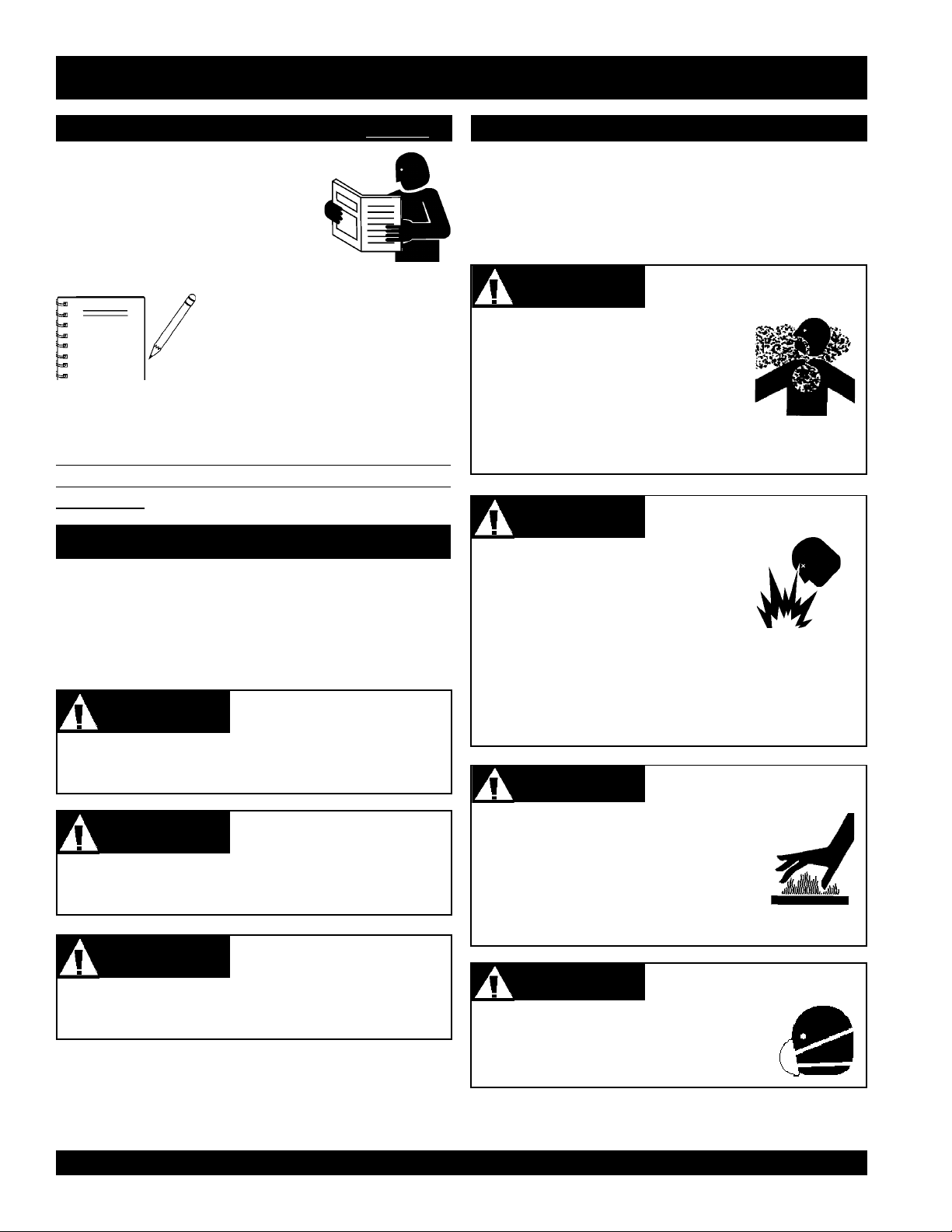
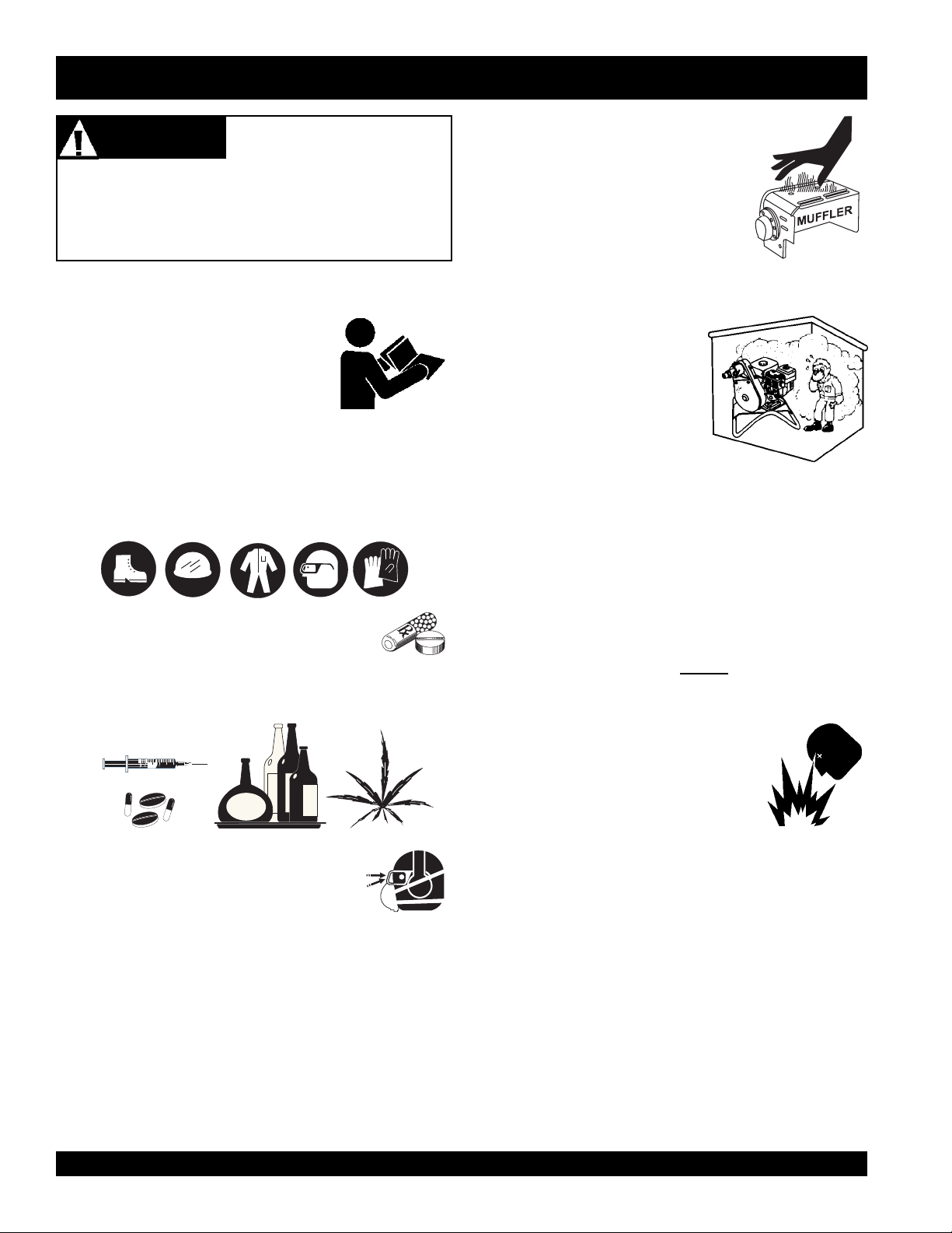
Engine exhaust gases contain
poisonous carbon monoxide. This gas
is colorless and odorless, and can
cause death if inhaled. NEVER operate
this equipment in a confined area or
enclosed structure that does not provide ample free flow
air.
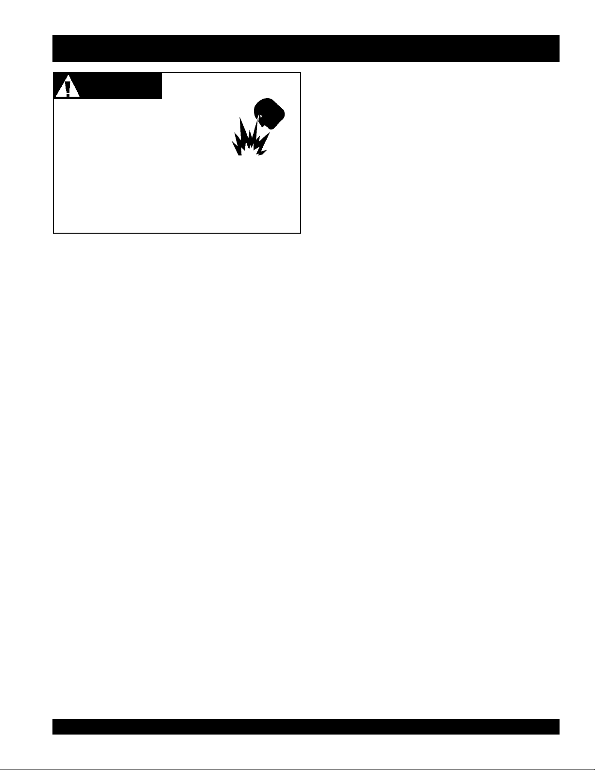
Gasoline is extremely flammable, and
its vapors can cause an explosion if
ignited. DO NOT start the engine near
spilled fuel or combustible fluids.
DO NOT fill the fuel tank while the engine is running or
hot. DO NOT overfill tank, since spilled fuel could ignite if
it comes into contact with hot engine parts or sparks from
the ignition system. Store fuel in approved containers, in
well-ventilated areas and away from sparks and flames.
Lethal Exhaust Gases
WARNINGWARNING
WARNING
WARNINGWARNING
WARNINGWARNING
WARNING
WARNINGWARNING
WARNINGWARNING
WARNING
WARNINGWARNING
Lethal Exhaust Gas Hazards
Explosive Fuel Hazards
Burn Hazards
WARNINGWARNING
WARNING
WARNINGWARNING
You CAN be
NOT follow directions.
CAUTION
You CAN be
KILLED
CAUTIONCAUTION
CAUTION
CAUTIONCAUTION
INJURED
PAGE 6 — G-55H GASOLINE VIBRATOR — OPERATION & PARTS MANUAL — REV. #0 (03/07/06)
or
SERIOUSLY
if you DO NOT follow directions.
injured if you DO
Engine components can generate extreme
heat. To prevent burns, DO NOT touch
these areas while the engine is running or
immediately after operations. Never
operate the engine with heat shields or heat
guards removed.
WARNINGWARNING
WARNING
WARNINGWARNING
ALWAYS wear approved
protection when required.
Respiratory Hazards
respiratory
Page 7
G-55H GASOLINE VIBRATOR — SAFETY MESSAGE ALERT SYMBOLS
CAUTIONCAUTION
CAUTION
CAUTIONCAUTION
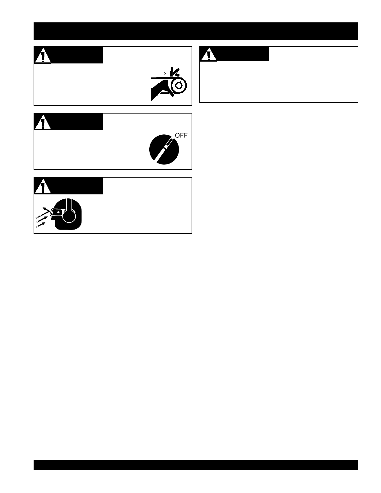
NEVER operate equipment with covers,
or guards removed. Keep fingers, hands,
hair and clothing away from all moving
parts to prevent injury.
CAUTIONCAUTION
CAUTION
CAUTIONCAUTION
ALWAYS place the ON/OFF switch in
the OFF position.
CAUTIONCAUTION
CAUTION
CAUTIONCAUTION
ALWAYS wear approved eye and
hearing protection.
Rotating Parts Hazards
Accidental Starting Hazards
Eye and Hearing Hazards
CAUTIONCAUTION
CAUTION
CAUTIONCAUTION
Other important messages are provided throughout this
manual to help prevent damage to your equipment, other
property, or the surrounding environment.
Equipment Damage
Hazards
G-55H GASOLINE VIBRATOR — OPERATION & PARTS MANUAL — REV. #0 (03/07/06) — PAGE 7
Page 8
G-55H GASOLINE VIBRATOR — RULES FOR SAFE OPERATION
■
DANGERDANGER
DANGER
DANGERDANGER
Failure to follow instructions in this manual may lead to
serious injury or even death! This equipment is to be
operated by trained and qualified personnel only! This
equipment is for industrial use only.
The following safety guidelines should always be used when
operating the G-55H Gasoline Vibrator:
GENERAL SAFETY
■
DO NOT operate or service this
equipment before reading this entire
manual.
■
This equipment should not be operated by persons under
18 years of age.
■
NEVER operate this equipment without proper protective
clothing, shatterproof glasses, steel-toed boots and other
protective devices required by the job.
Read this manual!
NEVER touch the hot exhaust
manifold, muffler or cylinder. Allow
these parts to cool before servicing
engine or vibrator.
■
High Temperatures – Allow the
engine to cool before adding fuel or
performing service and maintenance
functions. Contact with
serious burns.
■
The engine section of this
vibrator requires an adequate
free flow of cooling air.
NEVER
any enclosed or narrow area
where free flow of the air is
restricted. If the air flow is
restricted it will cause serious damage to the vibrator or
engine and may cause injury to people. Remember the
vibrator's engine gives off
gas.
hot!
components can cause
operate the vibrator in
DEADLY
carbon monoxide
■
NEVER operate this equipment when not
feeling well due to fatigue, llness or taking
medicine.
■
NEVER operate this equipment under the influence
of
drugs
■
ALWAYS wear proper respiratory (mask),
hearing and eye protection equipment
when operating the vibrator.
■
Whenever necessary, replace nameplate, operation and
safety decals when they become difficult read.
■
Manufacture does not assume responsibility for any
accident due to equipment modifications.
■
NEVER use accessories or attachments, which are not
recommended by Multiquip for this equipment. Damage
to the equipment and/or injury to user may result.
or
alcohol
.
■
ALWAYS refuel in a well-ventilated area, away from
sparks and open flames.
■
ALWAYS use extreme caution when working with
flammable liquids. When refueling, stop the engine and
allow it to cool. DO NOT
machine. Fire or explosion could result from fuel vapors,
or if fuel is spilled on a hot engine.
■
NEVER operate the equipment in an
explosive atmosphere or near
combustible materials. An explosion
or fire could result causing severe
smoke
around or near the
bodily harm or even death.
■
Topping-off to filler port is dangerous, as it tends to spill
fuel.
■
Stop the engine when leaving the vibrator unattended.
■
Maintain this equipment in a safe operating condition at
all times.
■
ALWAYS check to make sure the cutting area is clear
before starting the engine.
■
ALWAYS clear the work area of any debris, tools, etc.
that would constitute a hazard while the vibrator is in
operation.
PAGE 8 — G-55H GASOLINE VIBRATOR — OPERATION & PARTS MANUAL — REV. #0 (03/07/06)
Page 9
G-55H GASOLINE VIBRATOR — RULES FOR SAFE OPERATION
■
ALWAYS stop the engine before servicing, adding fuel
and oil.
■
NEVER run engine without air filter. Severe engine
damage may occur.
■
ALWAYS service air cleaner frequently to prevent
carburetor malfunction.
■
ALWAYS be sure the operator is familiar with proper
safety precautions and operations techniques before
using.
■
ALWAYS store equipment properly when it is not being
used. Equipment should be stored in a clean, dry location
out of the reach of children.
■
DO NOT operate this equipment unless all guards and
safety devices are attached and in place.
■
CAUTION must be exercised while servicing this
equipment. Rotating and moving parts can cause injury
if contacted.
■
Keep all
inexperienced
and
unauthorized
people away
from the equipment at all times.
■
Unauthorized equipment modifications will void all
warranties.
■
NEVER pour or spray water over the engine.
■
Test the
ON/OFF
switch for the gasoline engine before
operating. The purpose of these switches is to shut down
the engine of the vibrator.
■
Refer to the
HONDA Engine Owner's Manual
for engine
technical questions or information recommended by
Multiquip for this equipment. Damage to the equipment
and/or injury to user may result.
TRANSPORTING
■
ALWAYS shutdown engine before transporting.
■
Tighten fuel tank cap securely and close fuel cock to
prevent fuel from spilling.
■
ALWAYS use proper lifting techniques when using or
moving the vibrator motor, flexible shaft or vibrator head
assembly.
MAINTENANCE
■
NEVER lubricate components or attempt service on a
running vibrator.
■
ALWAYS allow the vibrator a proper amount of time to
cool before servicing.
■
Keep the vibrator in proper running condition.
■
Fix damage to the vibrator immediately and always
replace broken parts.
■
Dispose of hazardous waste properly. Examples of
potentially hazardous waste are used motor oil, fuel and
fuel filters.
■
DO NOT use food or plastic containers to dispose of
hazardous waste.
EMERGENCIES
■
ALWAYS know the location of the nearest
extinguisher
and first aid kit.
fire
■
In emergencies
the nearest phone or
job site
. Also know the phone numbers of the
nearest
department
always
know the location of
keep a phone on the
ambulance, doctor
and
. This information will be
fire
invaluable in the case of an emergency.
G-55H GASOLINE VIBRATOR — OPERATION & PARTS MANUAL — REV. #0 (03/07/06) — PAGE 9
Page 10
G-55H GASOLINE VIBRATOR — OPERATION AND SAFETY DECALS
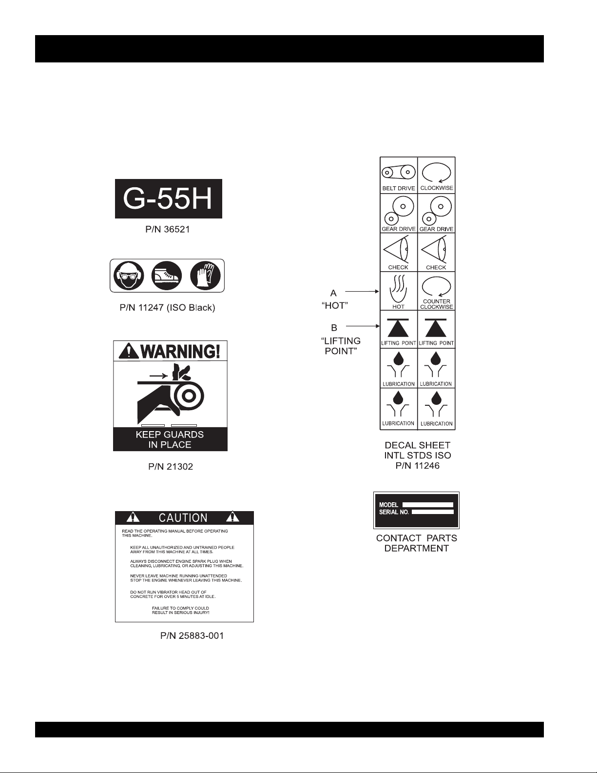
Operation And Safety Decals
The MQ/STOW G-55H Gasoline Vibrator is equipped with a number of operation and safety decals (Figure 1). These decals
are provided for operator safety and maintenance information. Should any of these decals become unreadable, replacements
can be obtained from your dealer.
Figure 1. Operation and Safety Decals
PAGE 10 — G-55H GASOLINE VIBRATOR — OPERATION & PARTS MANUAL — REV. #0 (03/07/06)
Page 11
G-55H GASOLINE VIBRATOR — GENERAL INFORMATION
General Information
The G-55H Gasoline Vibrator employs a 5.5 HP Honda engine.
It comes standard with a quick-disconnect coupling and an
eccentric belt tensioner.
The G-55H power unit utilizes a sturdy frame which enables
the engine to operate in a 360° rotation.
When operating the vibrator always wear rubber insulated
gloves and boots. Safety glasses are also recommended.
Theory Of Concrete Vibration
This G-55H vibrator is designed for the
concrete by removal of air pockets and voids.
The purpose of vibration is to set the particles in the fresh
concrete in motion, thereby reducing the friction between
the particles and giving the mixture the mobile quality of a
thick fluid so that gravity and the displacement of entrapped
air will cause it to settle easily into place.
By consolidating the concrete quickly, "stiffer" or "drier" mixes
Tips
can be poured than would otherwise be possible. It has
been proven that (up to a point) the drier the concrete, (that
■
Keep the bending radius of the flexible hose to a minimum
during use.
■
Avoid starting the unit with the vibrator head immersed in the
concrete mix. After the engine has started, immerse the vibrator
head into concrete mix.
■
Excessive wear to the vibrating head can result from misuse.
DO NOT allow the head to vibrate against already hardened
concrete or steel used in reinforcement.
■
NEVER drop or knock the vibrator head against any hard
objects. This will prevent any damage the eccentric or bearings
contain within the head.
is, the less water in it), the better the quality throughout and
the greater the strength. Drier mixes also make the concrete
more water tight, increase resistance to weathering, and
create a better bond between concrete and reinforcement.
Because vibration causes much of the entrapped air in the
concrete to rise to the surface, honeycombing is prevented.
Also, vibration eliminates most of the air pockets between
the concrete and the vertical forms.
compaction
of
■
ALWAYS rinse or wipe off any wet concrete before it dries or
hardens on any part of the unit
(engine, shaft, or head).
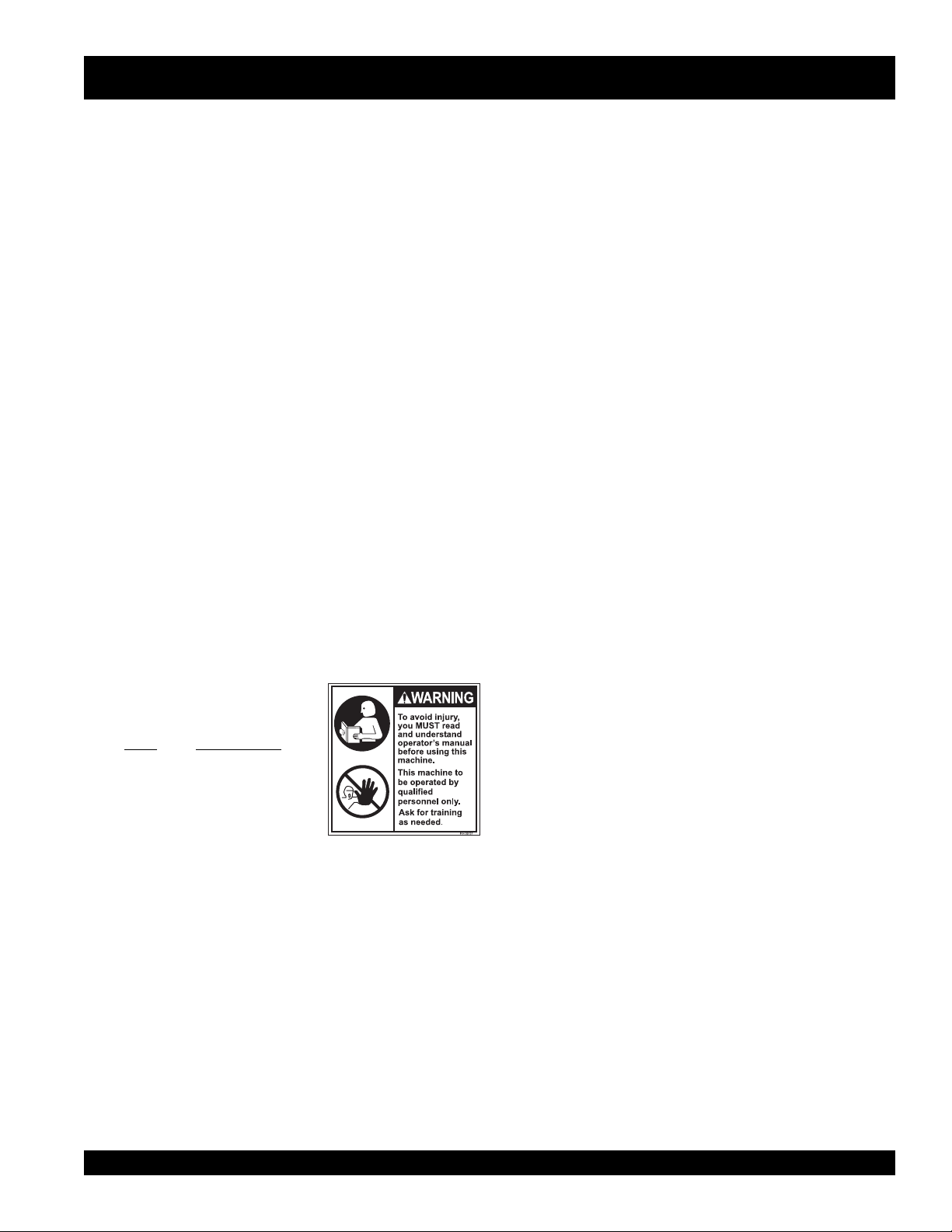
Before operating this gasoline
powered vibrator, the operator
must
read
and
understand
the
contents of the operation manual.
Failure to read this manual could
result in severe bodily harm and
damage to the equipment.
G-55H GASOLINE VIBRATOR — OPERATION & PARTS MANUAL — REV. #0 (03/07/06) — PAGE 11
Page 12
G-55H GASOLINE VIBRATOR — MAJOR COMPONENTS
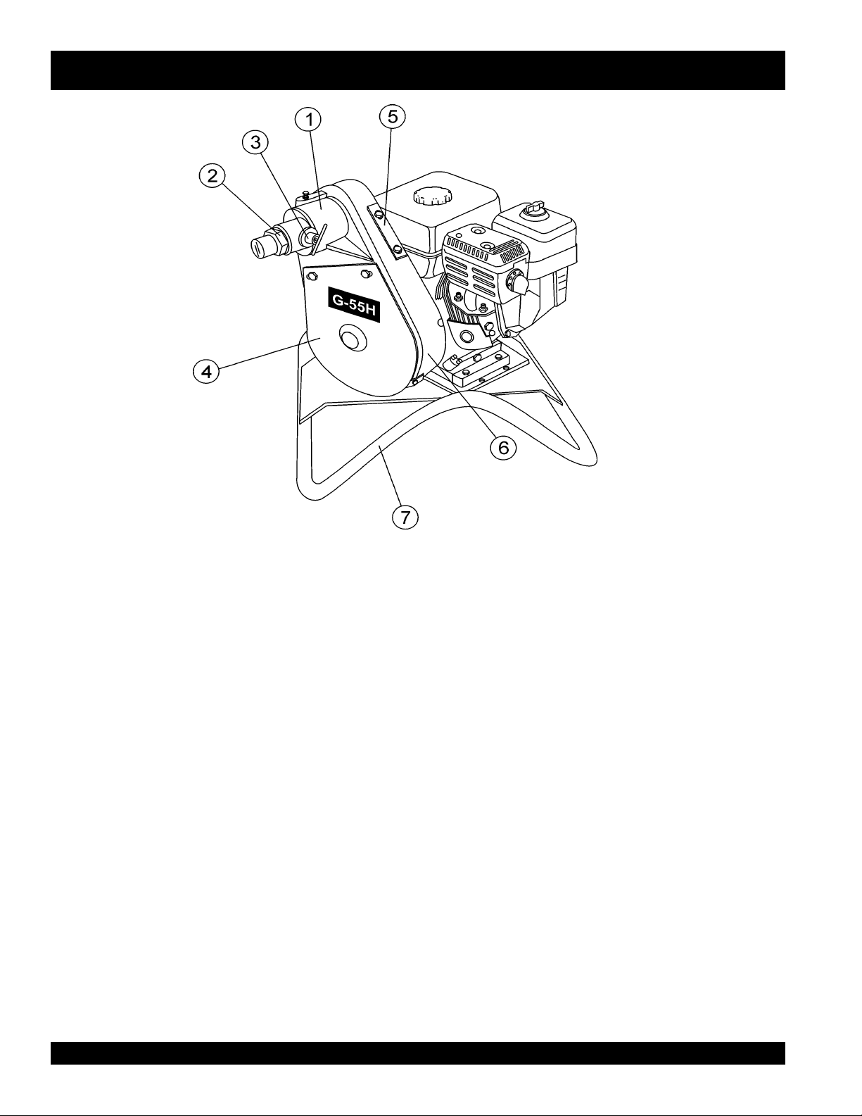
Figure 2. G-55H Gasoline Vibrator Components
Figure 2 shows the location of the components and general
maintenance parts. The function of each component is
described below:
1. Eccentric Bell End – Supports the spindle shaft and
upper pulley which drives the vibration function of the
G-55H. The flexible shaft and quick disconnect are
inserted into the open end of the Eccentric Bell.
2. 328V Quick Disconnect – Connect the flexible shaft to
the quick disconnect and insert into the eccentric bell.
This allows for rapid removal of the flexible shaft end
from the vibrator base.
3. Quick Disconnect Lock Pin – Pull up on the lock pin
and pull the flexible shaft out to release the quick
disconnect from the eccentric bell. To insert a flexible
shaft, pull up on the lock pin and insert the quick
disconnect fitting. Release the pin and turn the fitting
until the lock pin drops into one of the holes on the fitting
end.
5. Rear Belt Guard – Attaches to the V-belt housing and
prevents access to the pulleys or V-belts while the vibrator
is running. DO NOT operate the vibrator with this cover
removed.
6. V-belt Housing – Encloses the pulley's and v-belts.
Access is provided through openings in the front and
rear of the housing.
7. Vibrator Support Stand – Allows the vibrator base to
sit upright. A pivot mechanism allows the base to freely
pivot in a complete 360 degree circle for operators
convieniance.
4. Front Belt Guard – Attaches to the V-belt housing and
prevents access to the pulleys or V-belts while the vibrator
is running. DO NOT operate the vibrator with this cover
PAGE 12 — G-55H GASOLINE VIBRATOR — OPERATION & PARTS MANUAL — REV. #0 (03/07/06)
Page 13
G-55H GASOLINE VIBRATOR — ENGINE COMPONENTS
5.5 HP Honda Gasoline Engine
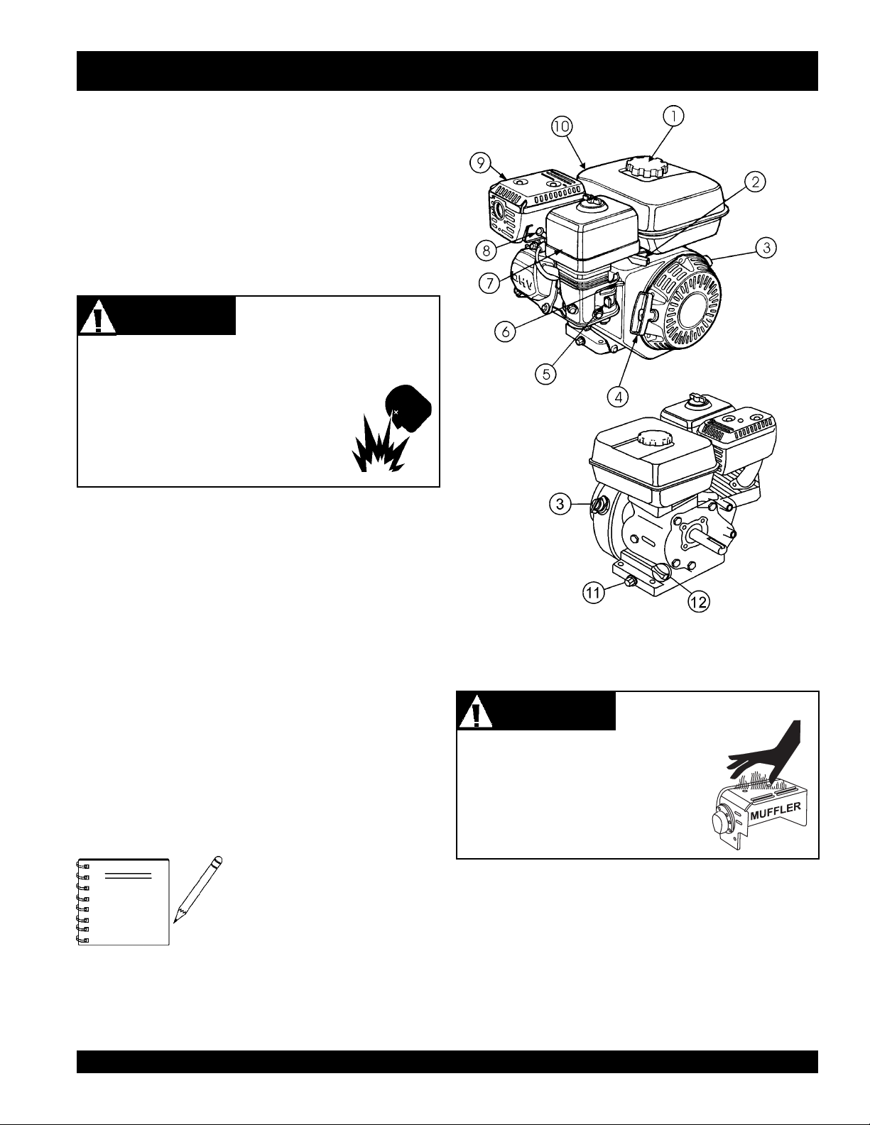
The engine (Figure 3) must be checked for proper lubrication
and filled with fuel prior to operation. Refer to the
manufacturer's engine manual for instructions & details of
operation and servicing. The engine shown above is a HONDA
engine. Operation for other types of engines may vary.
1. Fuel Filler Cap – Remove this cap to add unleaded
gasoline to the fuel tank. Make sure cap is tightened
securely. DO NOT over fill.
DANGERDANGER
DANGER
DANGERDANGER
Adding fuel to the tank should be done only when the
engine is stopped and has had an opportunity to cool
down. In the event of a fuel spill,
DO NOT attempt to start the engine until
the fuel residue has been completely
wiped up, and the area surrounding the
engine is dry.
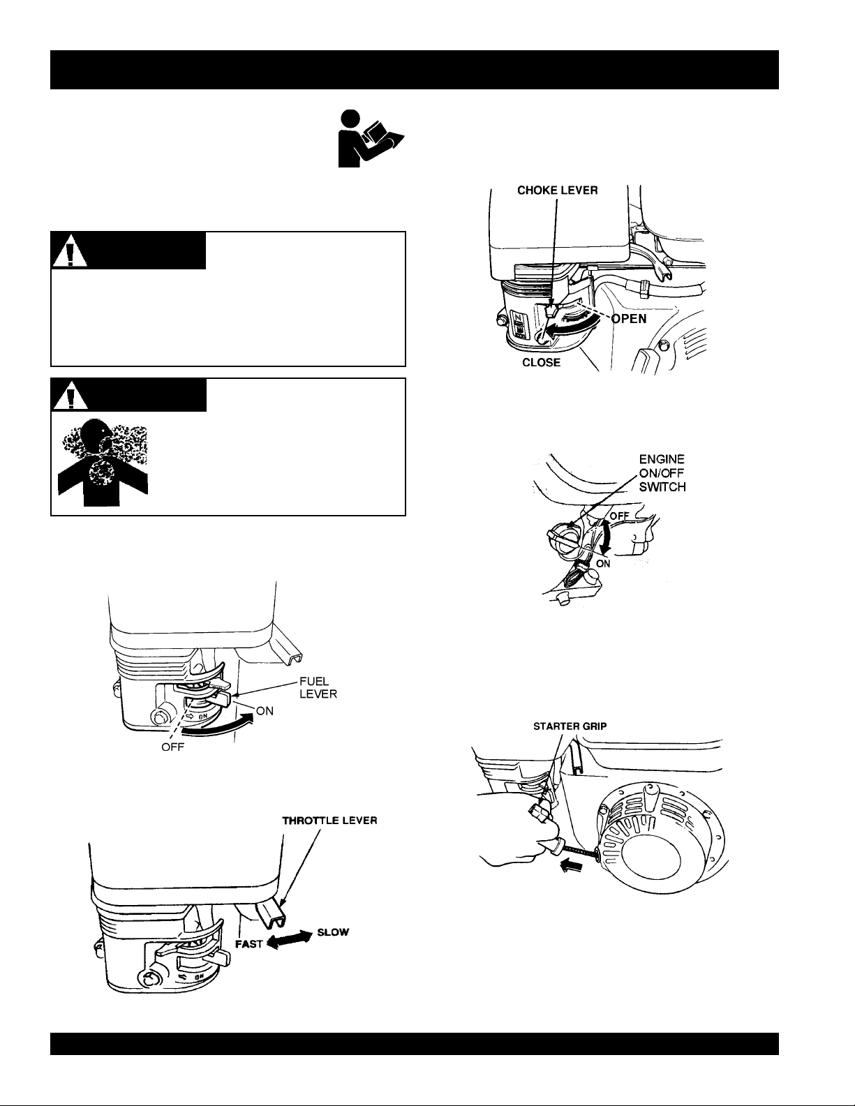
2. Throttle Lever – Used to adjust engine RPM speed
(lever advanced forward
operator
3. Engine ON/OFF Switch – ON position permits engine
starting,
4. Recoil Starter (pull rope) – Manual-starting method.
Pull the starter grip until resistance is felt, then pull
briskly and smoothly.
5. Fuel Valve Lever – OPEN to let fuel flow, CLOSE to
stop the flow of fuel.
6. Choke Lever – Used in the starting of a cold engine, or
in cold weather conditions. The choke enriches the fuel
mixture.
7. Air Cleaner – Prevents dirt and other debris from entering
the fuel system. Remove wing-nut on top of air filter
cannister to gain access to filter element.
NOTE
8. Spark Plug – Provides spark to the ignition system.
Clean spark plug once a week.
FAST
).
OFF
position stops engine operation.
Operating the engine without an air
filter, with a damaged air filter, or a
filter in need of replacement will
allow dirt to enter the engine,
causing rapid engine wear.
Explosive
Fuel Hazard
SLOW
, lever back toward
Figure 3. Honda GX160T1QX2 Engine Components
9. Muffler – Used to reduce noise and emissions.
Engine components can generate
extreme heat. To prevent burns, DO
NOT touch these areas while the engine
is running or immediately after
operating. NEVER operate the engine
with the muffler removed.
10. Fuel Tank – Holds unleaded gasoline. For additional
information refer to engine owner's manual.
11. Oil Drain Plug – Remove this plug to remove oil from
the engine's crankcase.
12. Dipstick/Oil Filler Cap – Remove this cap to determine
if the engine oil is low. Add oil through this filler port as
recommended in Table 3.
WARNINGWARNING
WARNING
WARNINGWARNING
Burn Hazard
G-55H GASOLINE VIBRATOR — OPERATION & PARTS MANUAL — REV. #0 (03/07/06) — PAGE 13
Page 14
G-55H GASOLINE VIBRATOR — INSPECTION
CAUTIONCAUTION
CAUTION
CAUTIONCAUTION
NEVER place hands or feet inside the belt
guard cover while the engine is running.
ALWAYS shut the engine down before
performing any kind of maintenance
service on the unit.
CAUTIONCAUTION
CAUTION
CAUTIONCAUTION
ALWAYS wear approved eye and
hearing protection before inspecting,
operating or servicing the vibrator.
Before Starting
Before starting and operating the G-55H Gasoline Vibrator,
perform the following:
■
Read safety instructions at the beginning of manual.
■
Clean the vibrator, removing dirt and dust, particularly
the engine cooling air inlet, carburetor and air cleaner.
■
Check the air filter for dirt and dust. If air filter is dirty,
replace air filter with a new one as required.
Inspection &
Maintenance Saftey
Eyesight and Hearing
Protection
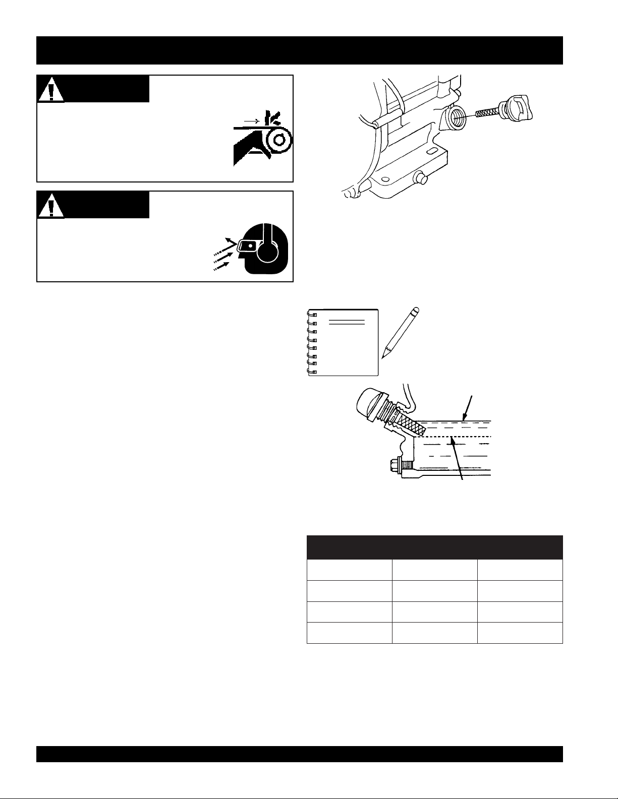
Figure 4. Engine Oil Dipstick (Removal)
3. Insert and remove the dipstick without screwing it into
the filler neck. Check the oil level shown on the dipstick.
4. If the oil level is low (Figure 5), fill to the edge of the oil
filler hole with the recommended oil type (Table 3).
Maximum oil capacity is 0.63 quarts (.60 liters).
NOTE
Reference manufacturer engine
manual for specific servicing
instructions.
UPPER LIMIT
■
Check carburetor for external dirt and dust. Clean with
dry compressed air.
■
Check fastening nuts and bolts for tightness.
■
Check the engine oil level of the engine.
■
Check the fuel level of the engine.
■
Check the tension and condition of the vibrator power
unit's V-belts.
Engine Oil Check
1. To check the engine oil level, place the vibrator on
secure level ground with the engine stopped.
2. Remove the filler dipstick from the engine oil filler hole
(Figure 4) and wipe clean.
LOWER LIMIT
Figure 5. Engine Oil Dipstick (Oil Level)
epyTliO.3elbaT
nosaeS erutarepmeT epyTliO
remmuS rehgiHroC°52 03-W01EAS
llaF/gnirpS C°01~C°52 02/03-W01EAS
retniW rewoLroC°0 01-W01EAS
PAGE 14 — G-55H GASOLINE VIBRATOR — OPERATION & PARTS MANUAL — REV. #0 (03/07/06)
Page 15
G-55H GASOLINE VIBRATOR — INSPECTION
WARNINGWARNING
WARNING
WARNINGWARNING
Gasoline is extremely flammable, and
its vapors can cause an explosion if
ignited. DO NOT start the engine near
spilled fuel or combustible fluids.
DO NOT fill the fuel tank while the engine is running or
hot. DO NOT overfill tank, since spilled fuel could ignite if
it comes into contact with hot engine parts or sparks from
the ignition system. Store fuel in approved containers, in
well-ventilated areas and away from sparks and flames.
1. Remove the gasoline cap located on top of fuel tank.
2. Visually inspect to see if fuel level is low. If fuel is low,
replenish with unleaded fuel.
3. When refueling, be sure to use a strainer for filtration. DO
NOT top-off fuel. Wipe up any spilled fuel.
Explosive Fuel Hazards
V-Belt Check
A worn or damaged V-belt can adversely affect the
performance of the vibrator.
1. Unscrew the bolts securing the front belt guard to the
belt housing
2. Inspect the belts for defects or wear.
3. If a V-belt is defective or worn, replace the V-belt as
outlined in the maintenance section of this manual.
Moving the Vibrator
Even though the vibrator is lightweight, always use two
people when lifting the vibrator or moving the unit around the
jobsite.
G-55H GASOLINE VIBRATOR — OPERATION & PARTS MANUAL — REV. #0 (03/07/06) — PAGE 15
Page 16
G-55H GASOLINE VIBRATOR — START-UP PROCEDURES
This section is intended to assist the operator
with initial start-up. It is extremely important
that this section be read carefully before
attempting to use the vibrator in the field.
DO NOT use your vibrator until this section is thoroughly
understood.
WARNINGWARNING
WARNING
WARNINGWARNING
Failure to understand the operation of this vibrator could
result in
See Figures 2 and 3 for the location of any control
referenced in this manual.
severe damage
CAUTIONCAUTION
CAUTION
CAUTIONCAUTION
NEVER operate the vibrator in a
confined area or enclosed area structure
that does not provide ample
of air
to the vibrator or
.
General Safety
personal injury
Respiratory Hazard
free flow
3. Place the engine
.
5. Place the engine
choke lever
position if starting a
in the OPEN position if starting a
temperature is warm.
Figure 8. Engine Choke Lever
position.
cold
ON/OFF switch
(Figure 8) in the CLOSED
engine. Place the
choke lever
warm engine
(Figure 9) in the ON
or the
Starting the Engine
1. Place the engine
position.
Figure 6. Engine Fuel Valve Lever
2. Place the engine
SLOW position.
fuel valve lever
throttle lever
(Figure 6) to the ON
(Figure 7) to the IDLE or
Figure 9. Engine ON/OFF Switch
6. Grasp the
it out. The resistance becomes the hardest at a certain
position, corresponding to the compression point. Pull
the starter grip briskly and smoothly for starting.
recoil starter grip
Figure 10. Starter Grip
(Figure 10) and slowly pull
Figure 7. Throttle Lever
PAGE 16 — G-55H GASOLINE VIBRATOR — OPERATION & PARTS MANUAL — REV. #0 (03/07/06)
Page 17

G-55H GASOLINE VIBRATOR — START-UP/SHUTDOWN PROCEDURES
7. If the engine has started, slowly return the choke lever
(Figure 6) to the OPEN position. If the engine has not
started repeat steps 1 through 6.
8. Before the vibrator is placed into operation, immerse the
vibrator head into the concrete and run the engine for
several minutes. Check for fuel leaks, and noises that
would associate with a loose V-belt cover or component.
CAUTIONCAUTION
CAUTION
CAUTIONCAUTION
The vibrator head is cooled by the concrete. Operation
of the vibrator head in air longer than 2 minutes will
cause overheating of the bearings which result in
premature head failure.
9. To begin use, move the throttle lever (Figure 6) toward the
FAST position.
Vibrator Head
Overheating Hazard
Stopping The Engine
1. Move the throttle lever to the IDLE or SLOW position
(Figure 11) and run the engine for three minutes at low
speed.
2. After the engine cools, turn the engine
to the OFF position (Figure 11).
Figure 11. Engine ON/OFF Switch (OFF Position)
3. Close the
fuel valve lever to the OFF position.
fuel shut- off valve
(Figure 12) by moving the
start/stop switch
Figure 12. Fuel Valve Lever (OFF Position)
G-55H GASOLINE VIBRATOR — OPERATION & PARTS MANUAL — REV. #0 (03/07/06) — PAGE 17
Page 18
G-55H GASOLINE VIBRATOR — OPERATION
Operation
Read
all the safety instructions carefully. Safety instructions
will be found throughout this manual and on the vibrator motor.
Keep all safety information available, accessible, and in good,
readable condition.
■
Make certain that the flexible shaft is properly attached
to the motor and the head to the flexible shaft.
■
Use the flexible shaft in as straight a position as possible.
■
Do not bend the flexible shaft sharply at any point.
Sharp bends may cause a permanent kink, requiring
early replacement of the flexible shaft.
Equipment Combination Information
The following Equipment Combination Chart shows all of
the recommended connections between the gasoline vibrator
and the vibrator head.
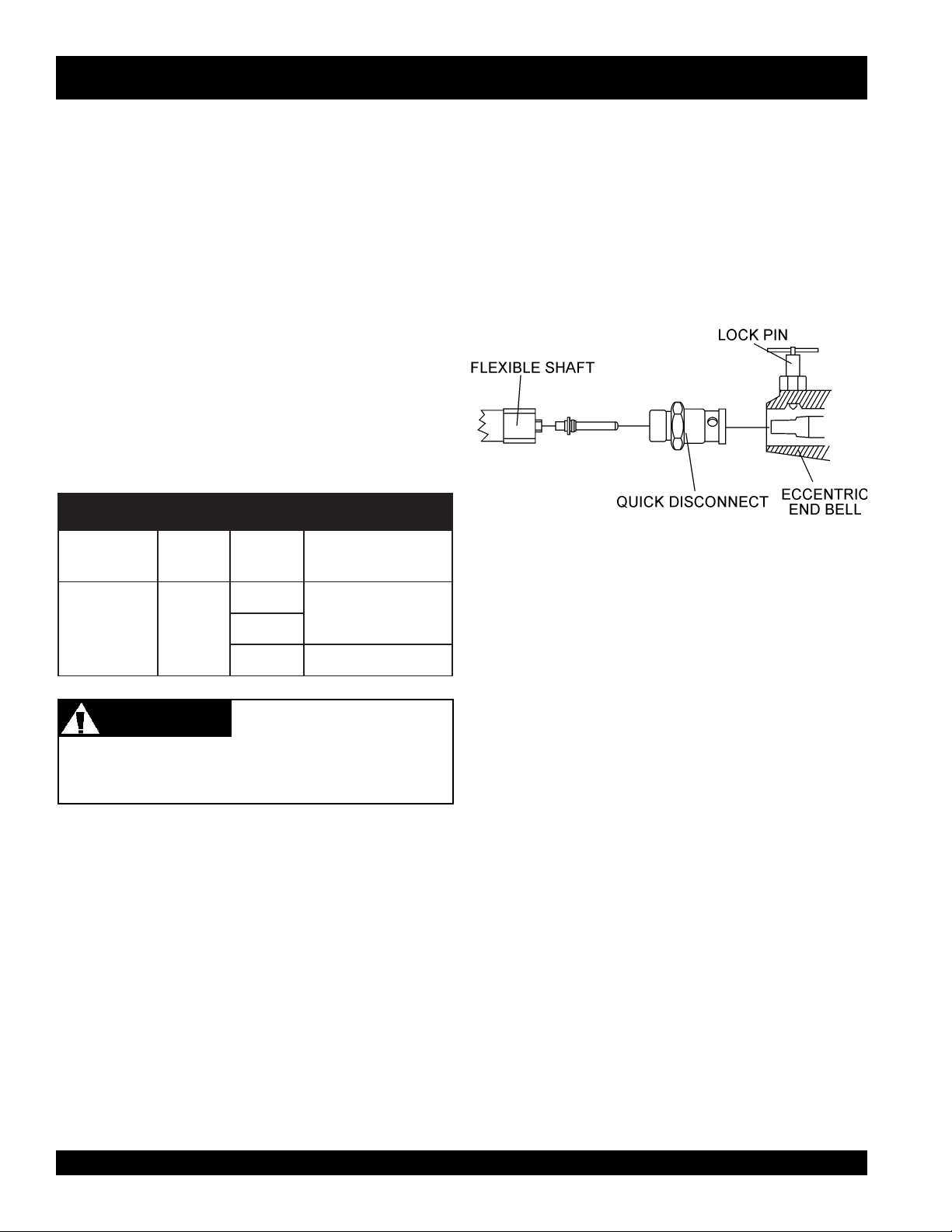
Connecting the 382V Flexible Shaft
1. Connect the 382V Flexible Shaft to the Quick Disconnect
coupling (Figure 13).
2. Pull UP on the lock pin and slide the shaft and quick
disconnect assembly into the eccentric end bell and
release the lock pin.
3. Twist the shaft assembly to make sure that the lock pin
is seated in one of the 3 tapered holes on the quick
disconnect coupling.
SNOITANIBMOCTNEMPIUQE.5ELBAT
GNILPUOCTFAHSDAEH
D.QV283V283
.biv0041
.biv0071
.biv0012)mc2.99(.tf12
TFAHSXAM
HTGNEL
Connecting the vibrator head to the flexible shaft
1. Clean the mating parts threads with Loctite Primer “T”.
)mc3.231(.tf82
2. Allow to dry several minutes before applying a ring of
Loctite No.271 to the middle of the casing threads.
Figure 13. Couplings
3. Screw the head tightly to the flexible shaft casing and
WARNINGWARNING
WARNING
WARNINGWARNING
Using head attachments not listed above may create a
hazardous condition when using the vibrator.
The G-55H Gasoline Vibrator, flexible shafting, and head
are shipped from the factory ready for assembly. Follow the
instructions listed below when connecting these parts before
using the gasoline vibrator.
Equipment Hazard
wait for 1 hour before using. The threads are left hand,
turn counter-clockwise to tighten. An equivalent brand
of anaerobic sealant may be used.
PAGE 18 — G-55H GASOLINE VIBRATOR — OPERATION & PARTS MANUAL — REV. #0 (03/07/06)
Page 19
G-55H GASOLINE VIBRATOR — OPERATION
1. Start the engine as previously described and procede to
insert the vibrator head into the concrete.
2. The concrete is normally placed into the forms in layers
about 12 to 18 inches thick in a manner which forms a
fairly level surface. The vibrator head is inserted
vertically into the top of the pile.
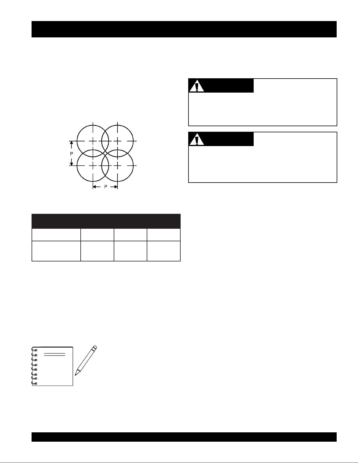
3. When the surface has become fairly level, the vibrator
head then should be immersed and generally moved in
the pattern shown in (Figure 14).
Figure 14. Compaction Coverage
with 50% Radial Overlap
Use the flexible shaft in as straight a position as possible
and do not bend the flexible shaft sharply at any point. Sharp
bends may cause a permanent kink, requiring early
replacement of the flexible shaft.
If the shaft begins to helix (buckle) excessively during
operation, stop and investigate. This is an indication of an
overload condition.
The vibrator head is cooled by the concrete. Operation
of the vibrator head in air longer than 2 minutes will
cause overheating of the bearings which result in
premature head failure.
CAUTIONCAUTION
CAUTION
CAUTIONCAUTION
CAUTIONCAUTION
CAUTION
CAUTIONCAUTION
Shaft Overload Hazard
Vibrator Head
Overheating Hazard
SNOISNEMID-PDNADAEH.4ELBAT
DAEH
NOISNEMID-P
■
Immerse the head for 5 to 10 seconds, (until air stops
rising), and then withdraw it slowly to let the concrete fill
the void left by the vibrator head.
■
The vibrator head should be completely below the surface
when vibrating to keep the head cool.
■
When vibrating a thin horizontal slab, the vibrator head
can be used in a horizontal position.
NOTE
004100710012
.ni8
)mm4.13(
DO NOT insert the vibrator head
into the side of the pile to make
the concrete flow as this practice
can cause segregation of the
aggregate from the mortar.
.ni21
).mm2.74(
.ni41
)mm1.55(
G-55H GASOLINE VIBRATOR — OPERATION & PARTS MANUAL — REV. #0 (03/07/06) — PAGE 19
Page 20

G-55H GASOLINE VIBRATOR — MAINTENANCE
Maintenance Instructions
To receive trouble-free service from your G-55H gasoline
vibrator, follow these instructions, as well as the instructions
contained in the engine operating manual, flexible shaft
operations manual and the vibrator head operations manual.
The 382V flexible shafting requires cleaning and lubrication
every 100 hours of operation. Refer to the flexible shaft
operation and parts manual for maintenance instructions.
Vibrator heads should be inspected and relubricated every
100 hours of operation.Refer to the vibrator head operation
and parts manual for maintenance instructions.
Heat should be used to break down
NOTE
WARNINGWARNING
WARNING
WARNINGWARNING
Whenever assembling, lubricating, or adjusting any part
of the gasoline vibrator make certain to stop the engine,
disconnect the spark plug wire and secure it away from
the spark plug.
the loctite while you unthread the
head from the shaft. This will
prevent possible damage to the
threads from the loctite.
Disabling the Engine
for Maintenance
■
Remove and clean the spark plug (Figure 24), then adjust
the spark gap to 0.024 ~0.028 inch (0.6~0.7 mm). This
unit has electronic ignition, which requires no
adjustments.
Engine Oil
1. Drain the engine oil when the oil is
Figure 25.
2. Remove the oil drain bolt and sealing washer and allow
the oil to drain into a suitable container.
3. Replace engine oil with recommended type oil as listed
in Table 3. For engine oil capacity, see Table 2 (engine
specifications). DO NOT overfill.
4. Install drain bolt with sealing washer and tighten securely.
Figure 15. Spark Plug Gap
warm
as shown in
Daily
■
Thoroughly remove dirt and oil from the engine and
control area. Clean or replace the air cleaner elements
as necessary. Check and retighten all fasteners as
necessary. Check the gearbox for oil leaks. Repair or
replace as needed.
Weekly
■
Remove the fuel filter cap and clean the inside of the
fuel tank.
■
Remove or clean the filter at the bottom of the tank.
Figure 16. Engine Oil (Draining)
Dispose of used oil properly. DO
NOTE
Used oil can generally be taken to your local recycling center
or service station for reclamation. Follow all required
environmental rules and regulations required in your area
concerning the disposal of hazardous waste such as used
oil and oil filters.
NOT pour used oil on the ground,
down a drain, or throw in the
trash.
PAGE 20 — G-55H GASOLINE VIBRATOR — OPERATION & PARTS MANUAL — REV. #0 (03/07/06)
Page 21
G-55H GASOLINE VIBRATOR — MAINTENANCE
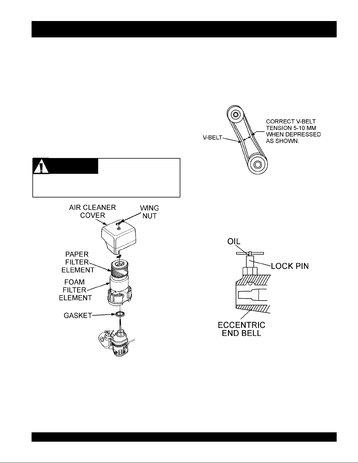
Engine Air Cleaner
1. Remove the air cleaner cover and foam filter element as
shown in Figure 26.
2. Tap the paper filter element (Figure 26) several times on
a hard surface to remove dirt, or blow compressed air
[not exceeding 30 psi (207 kPa, 2.1 kgf/cm
filter element from the air cleaner case side.
brush off dirt. Brushing will force dirt into the fibers.
Replace the paper filter element if it is excessively dirty.
3. Clean foam element in warm, soapy water or nonflammable solvent. Rinse and dry thoroughly. Dip the element
in clean engine oil and completely squeeze out the
excess oil from the element before installing.
DANGERDANGER
DANGER
DANGERDANGER
DO NOT use gasoline as a cleaning solvent to avoid
creating the risk of fire or an explosion.
Explosive Hazard
2
)] through the
NEVER
V-Belt Tension
The belt can be tightened by rotating the eccentric
countershaft assembly clockwise. When the belts are
properly tensioned, they should deflect approximately 5 to
10mm when 5-10 pounds of force is applied centrally between
the pulleys. Lock the countershaft in place with the locking
screw and wing nut.
Lubrication
Quick Disconnect Lock
A small amount of any lightweight oil should be used on the
locking mechanism to help keep concrete from sticking and
also to lubricate the locking pin and spring.
Figure 18. V-Belt Tension
Figure 19. Quick Disconnect Lock
Pivot Assembly
Figure 17. Engine Air Cleaner
G-55H GASOLINE VIBRATOR — OPERATION & PARTS MANUAL — REV. #0 (03/07/06) — PAGE 21
Grease with a pressure gun as required.
Page 22

G-55H GASOLINE VIBRATOR — TROUBLESHOOTING (ENGINE)
)ENIGNE(GNITOOHSELBUORT.5ELBAT
MOTPMYSESUACELBISSOPNOITULOS
?gnigdirbgulpkrapS
?gulpkrapsnotisopednobraC .gulpkrapsecalperronaelC
ontub,elbaliavasileuf",tratsottluciffiD
."gulpkrapstaKRAPS
dna,elbaliavasileuf",tratsottluciffiD
eserpsiKRAPS
."gulpkrapsehttatn
?noitalusni
?gnitiucric
ifedoteudtiucrictrohS
?paggulpkrapsreporpmI.pagreporp
?evitcefedliocnoitingI.liocnoitingiecalpeR
?detrohssihctiwsFFO/NO
?ytridstniop,pagkrapsreporpmI
trohsronrownoitalusniresnednoC
ronekorberiwgulpkrapS
?epytleufgnorW
gulpkrapstneic
.nrowfiecalper
otteS
.hctiws
.stniopnaelc
?gnitiucrictrohs
.gniriw
ronoitalusni,pagkcehC
.gulpkrapsecalper
,noitalusnigulpkrapskcehC
ecalper,gniriwhctiwskcehC
krapstcerrocteS
dnapag
.resnednocecalpeR
gulpkrapsevitcefedecalpeR
ecalperdna,metsysleufhsulF
.leuffoepyttcerrochtiw
kraps,elbaliavasileuf",tratsottluciffiD
inoisserpmocdnatneserpsi
ratsottluciffiD
."lamrons
kraps,elbaliavasileuf",t
."wolsinoisserpmocdnatneserpsi
t
.roterubracehttatneserpleufoN
udroretaW.metsysleufhsulF
?ytridrenaelcriA.renaelcriaecalpeR
?nepOekohC.ekohCesolC
?ylreporpdenethgi
?degamad
?deggolcretlifleuF.retlifleufecalpeR
niriA.enilleufdeelB
?enilleuf
?metsysleufnits
?dedurtorprokcutsevlavtsuahxe/noitcuS.sevlavtaes-eR
?nrowr
ednilycro/dnagnirnotsiP
tongulpkrapsro/dnadaehrednilyC
teksaggulpkrapsro/dnateksagdaeH
?)ypmeknat(knatleufnielbaliavatonleuF .leuffoepyttcerrochtiwlliF
?deggolcelohrehtaerbpacknatleuF .packnatleufecalperronaelC
.notsip
.gulpkraps
R
.steksag
ro/dnasgnirnotsipecalpeR
dnastlobdaehrednilyceuqroT
gulpkrapsro/dnadaehecalpe
PAGE 22 — G-55H GASOLINE VIBRATOR — OPERATION & PARTS MANUAL — REV. #0 (03/07/06)
Page 23

NOTE PAGE
G-55H GASOLINE VIBRATOR — OPERATION & PARTS MANUAL — REV. #0 (03/07/06) — PAGE 23
Page 24

G-55H VIBRATOR — EXPLANATION OF CODE IN REMARKS COLUMN
The following section explains the different symbols and remarks
used in the Parts section of this manual. Use the help numbers
found on the back page of the manual if there are any questions.
The contents and part numbers listed in the parts section are
subject to change
guarantee the availibility of the parts listed.
Sample Parts List:
NO. PART NO. PART NAME QTY. REMARKS
1 12345 BOLT ....................... 1 .... INCLUDES ITEMS W/
2
*
2*12347 WASHER, 3/8 IN. .... 1 ....
3 12348 HOSE .................... A/R .. MAKE LOCALLY
4 12349 BEARING ................ 1 .... S/N 2345B AND ABOVE
NO. Column
Unique Symbols - All items with same unique symbol
, #, +, %, or >) in the number column belong to the same
(
*
assembly or kit, which is indicated by a note in the “Remarks”
column.
Duplicate Item Numbers - Duplicate numbers indicate
multiple part numbers are in effect for the same general item,
such as different size saw blade guards in use or a part that
has been updated on newer versions of the same machine.
NOTE
without notice
WASHER, 1/4 IN. ...........
When ordering a part that has more
than one item number listed, check
the remarks column for help in
determining the proper part to order.
. Multiquip does not
NOT SOLD SEPARATELY
MQ-45T ONLY
QTY. Column
Numbers Used - Item quantity can be indicated by a number,
a blank entry, or A/R.
A/R (As Required) is generally used for hoses or other parts
that are sold in bulk and cut to length.
A blank entry generally indicates that the item is not sold
separately. Other entries will be clarified in the “Remarks”
Column.
REMARKS Column
Some of the most common notes found in the “Remarks”
*
Column are listed below. Other additional notes needed to
describe the item can also be shown.
Assembly/Kit
symbol will be included when this item is purchased.
Indicated by:
“INCLUDES ITEMS W/(unique symbol)”
Serial Number Break
range where a particular part is used.
Indicated by:
“S/N XXXXX AND BELOW”
“S/N XXXX AND ABOVE”
“S/N XXXX TO S/N XXX”
Specific Model Number Use
only with the specific model number or model number variant
listed. It can also be used to show a part is NOT used on a
specific model or model number variant.
Indicated by:
“XXXXX ONLY”
“NOT USED ON XXXX”
- All items on the parts list with the same unique
- Used to list an effective serial number
- Indicates that the part is used
PART NO. Column
Numbers Used - Part numbers can be indicated by a number,
a blank entry, or TBD.
TBD (To Be Determined) is generally used to show a part that
has not been assigned a formal part number at time of
publication.
A blank entry generally indicates that the item is not sold
separately or is not sold by Multiquip. Other entries will be
clarified in the “Remarks” Column.
PAGE 24 — G-55H GASOLINE VIBRATOR — OPERATION & PARTS MANUAL — REV. #0 (03/07/06)
“Make/Obtain Locally”
purchased at any hardware shop or made out of available
items. Examples include battery cables, shims, and certain
washers and nuts.
“Not Sold Separately”
purchased as a separate item and is either part of an
assembly/kit that can be purchased, or is not available for
sale through Multiquip.
- Indicates that the part can be
- Indicates that an item cannot be
Page 25

G-55H GASOLINE VIBRATOR — SPARE PARTS
G-55H GASOLINE VIBRATOR
1 TO 3 UNITS W/HONDA GX160K1QX2
ENGINE
Qty. P/N Description
3 ............ 9807956846 .......... SPARK PLUG
3 ............ 17210ZE2505 ....... ELEMENT, AIR CLEANER
1 ............ 28462ZE2W11 ...... ROPE STARTER
1 ............ 17620ZH7023 ....... CAP, W/GASKET FUEL FILLER
4 ............ 16052 .................... V-BELT 3VX335
G-55H GASOLINE VIBRATOR — OPERATION & PARTS MANUAL — REV. #0 (03/07/06) — PAGE 25
Page 26

G-55H GASOLINE VIBRATOR — NAMEPLATE AND DECALS
NAMEPLATE AND DECALS.
PAGE 26 — G-55H GASOLINE VIBRATOR — OPERATION & PARTS MANUAL — REV. #0 (03/07/06)
Page 27

G-55H GASOLINE VIBRATOR — NAMEPLATE AND DECALS
NAMEPLATE AND DECALS.
NO. PART NO. PART NAME
1 36521 DECAL, G-55H 1
2 11247 DECAL, HELMET, BOOT, GLOVES (ISO BLACK) 1
3 11246 DECAL, LIFT POINT ................................................. 2 ............ PART OF DECAL KIT 11246
4 11246 DECAL, HOT SURFACE ........................................... 1 ............ PART OF DECAL KIT 11246
5 NAMEPLATE............................................................. 1 ............ CONTACT MQ PARTS DEPT.
6 21665 DECAL, WARNING, KEEP GUARDS IN PLACE 2
7 25883-001 DECAL, CAUTION, READ MANUAL 1
G-55H GASOLINE VIBRATOR — OPERATION & PARTS MANUAL — REV. #0 (03/07/06) — PAGE 27
Page 28

ECCENTRIC/BODY ASSY.
G-55H GASOLINE VIBRATOR — ECCENTRIC/BODY ASSY.
PAGE 28 — G-55H GASOLINE VIBRATOR — OPERATION & PARTS MANUAL — REV. #0 (03/07/06)
Page 29

G-55H GASOLINE VIBRATOR — ECCENTRIC/BODY ASSY.
ECCENTRIC/BODY ASSY.
NO PART NO PART NAME QTY. REMARK
1 36248 COUPLING, SHAFT 1
2 18045-501 ECCENTRIC ASSY. ............................................. 1............... INCLUDES ITEMS W/#
3# 25015-501 LOCK ASSEMBLY 1
4# 08752-275 SNAP RING 2
5# 06330-002 BEARING SPRING 1
6# 14043-017 BEARING 2
7# 14546-001 SPINDLE 1
8# 08601-045 SPACER, SPLIT 1
9# 08751-156 SNAP RING 1
10# 06467-062 SPACER 1
11# 584013 KEY 3/16" x 3/16" x 1" 1
12# 2037 LOCKWASHER 5/16 1
13# 20875 CAP SCREW 5/16" -18 x 3/4 1
14 22538-001 SCREW - THREAD FORMING 8
15 25845-001 BELT GUARD (FRONT) 1
16 18024-001 HOUSING 1
17 0202 SCREW, HHC 5/16"-18 x 1 1
18 0106 NUT, HEX JAM 5/16"-18 1
19 36517 QD BUSHING 1
20# 18044-001 PULLEY (UPPER) 1
21 36516 PULLEY (LOWER) 1
22 16052 BELT 3VX335 2
23 0627 KEY - 3/16 SQ. x 1-1/4 1
24 25846-001 BELT GUARD (REAR) 1
25# 11534-018 CAP, DUST 1
26 27100-351 FRAME ASSEMBLY 1
27 1386 ENGINE - 5.5 HP HONDA 1
G-55H GASOLINE VIBRATOR — OPERATION & PARTS MANUAL — REV. #0 (03/07/06) — PAGE 29
Page 30

PIVOT ASSY.
G-55H GASOLINE VIBRATOR — PIVOT ASSY.
PAGE 30 — G-55H GASOLINE VIBRATOR — OPERATION & PARTS MANUAL — REV. #0 (03/07/06)
Page 31

G-55H GASOLINE VIBRATOR — PIVOT ASSY.
PIVOT ASSY.
NO PART NO PART NAME QTY. REMARK
1 5283 NUT - GRIPCO 5/16 - 18 4
2 0300 B FLATWASHER 5/16 4
3 0105 HHCS 5/16 - 18 x 1 1/2 4
4 27108-351 ENGINE PLATE - PIVOT 1
5 2621 GREASE FITTING 1
6 3264 FLATWASHER 1" 2
7 07028-057 COTTER PIN 5/32" x 1-1/2 1
G-55H GASOLINE VIBRATOR — OPERATION & PARTS MANUAL — REV. #0 (03/07/06) — PAGE 31
Page 32

AIR CLEANER ASSY.
HONDA GX160K1QX2 ENGINE — AIR CLEANER ASSY.
PAGE 32 — G-55H GASOLINE VIBRATOR — OPERATION & PARTS MANUAL — REV. #0 (03/07/06)
Page 33

HONDA GX160K1QX2 ENGINE — AIR CLEANER ASSY.
AIR CLEANER ASSY.
NO. PART NO. PART NAME QTY. REMARKS
1 16271ZE1000 GASKET, ELBOW 1
2 17210ZE1505 ELEMENT, AIR CLEANER (DUAL) 1
3 17218ZE1821 FILTER, OUTER 1
4 17230ZE1820 COVER, AIR CLEANER (DUAL) 1
5 17232891000 GROMMET, AIR CLEANER 1
6 17238ZE7010 COLLAR, AIR CLEANER 2
7 17239ZE1000 COLLAR B, AIR CLEANER 1
8 17410ZE1020 ELBOW, AIR CLEANER 1
9 90201415000 NUT, CAP 6MM 2
11 90325044000 WINGNUT, TOOL BOX SETTING 1
12 90325044000 WINGNUT, TOOL BOX SETTING 1
13 957010602000 BOLT, FLANGE 6 X 20 1
G-55H GASOLINE VIBRATOR — OPERATION & PARTS MANUAL — REV. #0 (03/07/06) — PAGE 33
Page 34

CAMSHAFT ASSY.
HONDA GX160K1QX2 ENGINE — CAMSHAFT ASSY.
PAGE 34 — G-55H GASOLINE VIBRATOR — OPERATION & PARTS MANUAL — REV. #0 (03/07/06)
Page 35

HONDA GX160K1QX2 ENGINE — CAMSHAFT ASSY.
CAMSHAFT ASSY.
NO. PART NO. PART NAME QTY. REMARKS
1 14100ZE1812 CAMSHAFT ASSEMBLY 1
2 14410ZE1010 ROD, PUSH 2
3 14431ZE1000 ARM, VALVE ROCKER 2
4 14441ZE1010 LIFTER, VALVE 2
5 14451ZE1013 PIVOT, ROCKER ARM 2
6 14568ZE1000 SPRING, WEIGHT RETURN 1
7 14711ZF1000 VALVE, INTAKE 1
8 14721ZF1000 VALVE, EXHAUST 1
9 14751ZF1000 SPRING VALVE 2
10 14771ZE1000 RETAINER, INTAKE VALVE SPRING 1
11 14773ZE1000 RETAINER, EXHAUST VALVE SPRING 1
12 14781ZE1000 ROTATOR, VALVE 1
13 14791ZE1010 PLATE, PUSH ROD GUIDE 1
14 90012ZE0010 BOLT, PIVOT 8MM 2
15 90206ZE1000 NUT, PIVOT ADJ. 2
G-55H GASOLINE VIBRATOR — OPERATION & PARTS MANUAL — REV. #0 (03/07/06) — PAGE 35
Page 36

CARBURETOR ASSY.
HONDA GX160K1QX2 ENGINE — CARBURETOR ASSY.
PAGE 36 — G-55H GASOLINE VIBRATOR — OPERATION & PARTS MANUAL — REV. #0 (03/07/06)
Page 37

HONDA GX160K1QX2 ENGINE — CARBURETOR ASSY.
CARBURETOR ASSY.
NO. PART NO. PART NAME QTY. REMARKS
1
#+% 16010ZE1812 GASKET SET 1
*
2
*
3 16013ZE0005 FLOAT SET 1
4
*
5
*
6
# 16024ZE1811 SCREW SET, DRAIN ................................... 1 ........... INCLUDES ITEM W/+
*
7
*
8
*
9 16100ZH8W51 CARBURETOR ASSEMBLY, BE65B B ........ 1 ........... INCLUDES ITEMS/
10
*
11
*
12
*
13 16211ZE1000 INSULATOR, CARBURETOR 1
14 16212ZH8800 GASKET, INSULATOR 1
15 16220ZE1020 SPACER, CARBURETOR 1
16 16221ZH8801 GASKET, CARBURETOR 1
17 16610ZE1000 LEVER, CHOKE STANDARD ....................... 1 ............ INCLUDES ITEM W/$
18
*
19 16954ZE1812 PLATE, LEVER SETTING 1
20
*
21
*
22
*
23
*
24$ 9430520122 PIN, SPRING 2 X 12 1
25
*
25
*
26
*
16011ZE0005 VALVE SET, FLOAT 1
16015ZE0831 CHAMBER SET, FLOAT ............................... 1 ........... INCLUDES ITEMS/#
16016ZH7W01 SCREW SET 1
16028ZE0005 SCREW SET B ............................................ 1 ........... INCLUDES ITEM W/%
16044ZE0005 CHOKE SET 1
16124ZE0005 SCREW, THROTTLE STOP 1
16166ZH8W50 NOZZLE, MAIN 1
16173001004 O- RING 1
16953ZE1812 LEVER, VALVE 1
16956ZE1811 SPRING, VALVE LEVER 1
16957ZE1812 GASKET, VALVE 1
16967ZE0811 CUP, FUEL STRAINER 1
93500030060H SCREW, PAN 3 X 6 2
99101ZH80650 JET, MAIN #65 (OPTIONAL) 1
99101ZH80680 JET, MAIN #68 (OPTIONAL) 1
99204ZE00350 JET SET, PILOT #35 1
*
G-55H GASOLINE VIBRATOR — OPERATION & PARTS MANUAL — REV. #0 (03/07/06) — PAGE 37
Page 38

CONTROL ASSY.
HONDA GX160K1QX2 ENGINE — CONTROL ASSY.
PAGE 38 — G-55H GASOLINE VIBRATOR — OPERATION & PARTS MANUAL — REV. #0 (03/07/06)
Page 39

HONDA GX160K1QX2 ENGINE — CONTROL ASSY.
CONTROL ASSY.
NO. PART NO. PART NAME QTY. REMARKS
2 16500ZH8823 CONTROL ASSEMBLY, REMOTE ......................... 1............ INCLUDES ITEMS W/
4 16551ZE0010 ARM, GOVERNOR 1
5 16555ZE1000 ROD, GOVERNOR 1
6 16561ZE1020 SPRING GOVERNOR 1
7 16562ZE1020 SPRING, THROTTLE RETURN 1
8
*
9
*
10
11
12
13
14
15
17 90013883000 BOLT, FLANGE 6 X 12 (CT200) 2
18 90016ZE5010 BOLT, GOVERNOR ARM 1
19
22
23
24 9405006000 NUT, FLANGE 6MM 1
16571ZH8020 LEVER, CONTROL 1
16574ZE1000 SPRING, LEVR 1
16575ZH8000 WASHER, CONTROL LEVER 1
*
16576891000 HOLDER, CABLE 1
*
16578ZE1000 SPACER, CONTROL LEVER 1
*
16580ZH8812 BASE, CONTROL (REMOTE) 1
*
16584883300 SPRING, CONTROL ADJUSTING 1
*
16592ZE1810 SPRING, CABLE RETURN 1
*
90114SA0000 NUT, SELF- LOCK 6MM 1
*
93500050250H SCREW, PAN 5 X 25 1
*
938930501600 SCREW, WASHER 5 X 16 1
*
*
G-55H GASOLINE VIBRATOR — OPERATION & PARTS MANUAL — REV. #0 (03/07/06) — PAGE 39
Page 40

HONDA GX160K1QX2 ENGINE — CRANKCASE COVER ASSY.
CRANKCASE COVER ASSY.
PAGE 40 — G-55H GASOLINE VIBRATOR — OPERATION & PARTS MANUAL — REV. #0 (03/07/06)
Page 41

HONDA GX160K1QX2 ENGINE — CRANKCASE COVER ASSY.
CRANKCASE COVER ASSY.
NO. PART NO. PART NAME QTY. REMARKS
1 11300ZE1641 COVER ASSEMBLY, CRANKCASE (U- TYPE) ..... 1 ........... INCLUDES ITEMS W/
3 11381ZH8801 GASKET, CASE COVER (NON- ASBESTOS) 1
4 15600ZE1003 CAP ASSEMBLY, OIL FILLER 1
5 15600ZG4003 CAP ASSEMBLY, OIL FILLER 1
9 15625ZE1003 GASKET, OIL FILLER CAP 1
10 15625ZE1003 GASKET, OIL FILLER CAP 1
11
12 9430108140 PIN A, DOWEL 8 X 14 2
13 957010803200 BOLT, FLANGE 8 X 32 6
14
91202883005 OIL SEAL 25 X 41 X 6 1
*
961006205000 BEARING, RADIAL BALL 6205 1
*
*
G-55H GASOLINE VIBRATOR — OPERATION & PARTS MANUAL — REV. #0 (03/07/06) — PAGE 41
Page 42

HONDA GX160K1QX2 ENGINE — CRANKSHAFT/BALANCER ASSY.
CRANKSHAFT /BALANCER WEIGHT ASSY.
PAGE 42 — G-55H GASOLINE VIBRATOR — OPERATION & PARTS MANUAL — REV. #0 (03/07/06)
Page 43

HONDA GX160K1QX2 ENGINE — CRANKSHAFT/BALANCER ASSY.
CRANKSHAFT ASSY.
NO. PART NO. PART NAME QTY. REMARKS
3 13310ZE1601 CRANKSHAFT, Q- TYPE 1
9 90745ZE1600 KEY, 4.78 X 4,78 X 38 1
G-55H GASOLINE VIBRATOR — OPERATION & PARTS MANUAL — REV. #0 (03/07/06) — PAGE 43
Page 44

HONDA GX160K1QX2 ENGINE — CYLINDER BARREL ASSY.
CYLINDER BARREL ASSY.
PAGE 44 — G-55H GASOLINE VIBRATOR — OPERATION & PARTS MANUAL — REV. #0 (03/07/06)
Page 45

HONDA GX160K1QX2 ENGINE — CYLINDER BARREL ASSY.
CYLINDER BARREL ASSY.
NO. PART NO. PART NAME QTY. REMARKS
2 12000ZH8811 CYLINDER ASSEMBLY, OIL ALERT .................... 1............ INCLUDES ITEMS W/
3 15510ZE1033 SWITCH ASSEMBLY, OIL LEVEL ......................... 1 ........... INCLUDES ITEMS W/%
4
*
5
*
6
*
8
*
9 16541ZE1000 SHAFT, GOVERNOR ARM 1
10 90131ZE1000 BOLT, DRAIN PLUG 2
11
12 90601ZE1000 WASHER, DRAIN PLUG 10.2MM 2
13
14% 91001ZF1003 BEARING, RADIAL BALL 6205 1
15% 91202883005 OIL SEAL 25 X 41 X 6 1
16 91353671003 O- RING 13.5 X 1.5 (ARAI) 1
17 9405010000 NUT, FLANGE 10MM 1
18
19 9425108000 PIN, LOCK 8MM 1
20 957010601200 BOLT, FLANGE 6 X 12 2
16510ZE1000 GOVERNOR ASSEMBLY ...................................... 1 ............ INCLUDES ITEMS W/#
# 16511ZE1000 WEIGHT, GOVERNOR 2
# 16512ZE1000 HOLDER, GOVERNOR WEIGHT 1
16531ZE1000 SLIDER, GOVERNOR 1
80451ZE1000 WASHER, THRUST 6MM 1
*
90602ZE1000 CLIP, GOVERNOR HOLDER 1
*
9410106800 WASHER, PLAIN 6MM 2
*
*
G-55H GASOLINE VIBRATOR — OPERATION & PARTS MANUAL — REV. #0 (03/07/06) — PAGE 45
Page 46

CYLINDER HEAD ASSY.
HONDA GX160K1QX2 ENGINE — CYLINDER HEAD ASSY.
PAGE 46 — G-55H GASOLINE VIBRATOR — OPERATION & PARTS MANUAL — REV. #0 (03/07/06)
Page 47

HONDA GX160K1QX2 ENGINE — CYLINDER HEAD ASSY.
CYLINDER HEAD ASSY.
NO. PART NO. PART NAME QTY. REMARKS
1 12210ZH8000 CYLINDER HEAD ..................................................1............ INCLUDES ITEMS W/
2
*
3
*
4% 12216ZE5300 CLIP, VALVE GUIDE 1
5 12251ZF1800 GASKET, CYLINDER HEAD 1
6 12310ZE1010 COVER, HEAD 1
7 12391ZE1000 GASKET, CYLINDER HEAD COVER 1
8 15721ZH8000 TUBE, BREATHER 1
9 90016ZE1000 BOLT, FLANGE 6 X13 4
10 90043ZE1020 BOLT, STUD 6 X10⁹ 2
11 90047ZE1000 BOLT, STUD 8 X 32 2
12 9430110160 PIN A, DOWEL 10 X16 2
14 957230806000 BOLT, FLANGE 8 X60 4
15 9807956846 SPARK PLUG BPR6ES (NGK) 1
12204ZE1306 GUIDE, VALVE OS (OPTIONAL 1
12205ZE1315 GUIDE, EXHAUST VALVE OS (OPTIONAL) ......... 1 ............ INCLUDES ITEM W/%
*
G-55H GASOLINE VIBRATOR — OPERATION & PARTS MANUAL — REV. #0 (03/07/06) — PAGE 47
Page 48

FAN COVER ASSY.
HONDA GX160K1QX2 ENGINE — FAN COVER ASSY.
PAGE 48 — G-55H GASOLINE VIBRATOR — OPERATION & PARTS MANUAL — REV. #0 (03/07/06)
Page 49

HONDA GX160K1QX2 ENGINE — FAN COVER ASSY.
FAN COVER ASSY.
NO. PART NO. PART NAME QTY. REMARKS
2 19610ZE1000ZC COVER, FAN "NH1" (BLACK) 1
4 19611ZH8810 PLATE, SIDE (OIL ALERT) 1
7 90601ZH7013 CLIP, HARNESS 1
8 19630ZH8000 SHROUD 1
10 32197ZH8003 SUB- HARNESS 1
11 36100ZE1015 SWITCH ASSEMBLY, ENGINE STOP 1
13 90013883000 BOLT, FLANGE 6 X12 (CT200) 6
14 90022888010 BOLT, FLANGE 6 X20 (CT200) 1
17 34150ZH7003 ALERT UNIT, OIL 1
19 957010600800 BOLT, FLANGE 6 X8 1
G-55H GASOLINE VIBRATOR — OPERATION & PARTS MANUAL — REV. #0 (03/07/06) — PAGE 49
Page 50

FLYWHEEL ASSY.
HONDA GX160K1QX2 ENGINE — FLYWHEEL ASSY.
PAGE 50 — G-55H GASOLINE VIBRATOR — OPERATION & PARTS MANUAL — REV. #0 (03/07/06)
Page 51

HONDA GX160K1QX2 ENGINE — FLYWHEEL ASSY.
FLYWHEEL ASSY.
NO. PART NO. PART NAME QTY. REMARKS
1 13331357000 KEY, SPECIAL WOODRUFF (25 X18) 1
2 19511ZE1000 FAN, COOLING 1
4 28451ZH8003 PULLEY, STARTER 1
5 31100ZE1010 FLYWHEEL 1
5 31100ZE1810 FLYWHEEL, LAMP 1
8 90201878003 NUT, SPECIAL 14MM 1
G-55H GASOLINE VIBRATOR — OPERATION & PARTS MANUAL — REV. #0 (03/07/06) — PAGE 51
Page 52

FUEL TANK ASSY.
HONDA GX160K1QX2 ENGINE — FUEL TANK ASSY.
PAGE 52 — G-55H GASOLINE VIBRATOR — OPERATION & PARTS MANUAL — REV. #0 (03/07/06)
Page 53

HONDA GX160K1QX2 ENGINE — FUEL TANK ASSY.
FUEL TANK ASSY.
NO. PART NO. PART NAME QTY. REMARKS
1 16854ZH8000 RUBBER, SUPPORTER 107MM 1
2 16955ZE1000 JOINT, FUEL TANK 1
3 17510ZE1020ZB TANK, FUEL *R8* (BRIGHT RED) 1
3 17510ZE1020ZF TANK, FUEL *NH1* (BLACK) 1
5 17620ZH7023 CAP, FUEL FILLER ............................................... 1 ........... INCLUDES ITEM W/
6
*
11 91353671003 O- RING 13.5 X1.5 (ARAI) 1
12 9405006000 NUT, FLANGE 6MM 2
13 950014500360M BULK HOSE, FUEL 4.5 X 3000 (4.5 X 140) 1
14 9500202080 CLIP, TUBE B8 2
15 957010602500 BOLT, FLANGE 6 X 25 1
17631ZH7003 GASKET, FUEL FILLER CAP 1
*
G-55H GASOLINE VIBRATOR — OPERATION & PARTS MANUAL — REV. #0 (03/07/06) — PAGE 53
Page 54

IGNITION COIL ASSY.
HONDA GX160K1QX2 ENGINE — IGNITION COIL ASSY.
PAGE 54 — G-55H GASOLINE VIBRATOR — OPERATION & PARTS MANUAL — REV. #0 (03/07/06)
Page 55

HONDA GX160K1QX2 ENGINE — IGNITION COIL ASSY.
IGNITION COIL ASSY.
NO. PART NO. PART NAME QTY. REMARKS
1 30500ZE1033 COIL ASSEMBLY, IGNITION 1
2 30700ZE1013 CAP ASSEMBLY, NOISE SUPPRESSOR 1
7 36101ZE1010 WIRE, STOP SWITCH 370MM 1
11 90121952000 BOLT, FLANGE 6 X25 2
G-55H GASOLINE VIBRATOR — OPERATION & PARTS MANUAL — REV. #0 (03/07/06) — PAGE 55
Page 56

MUFFLER ASSY.
HONDA GX160K1QX2 ENGINE — MUFFLER ASSY.
PAGE 56 — G-55H GASOLINE VIBRATOR — OPERATION & PARTS MANUAL — REV. #0 (03/07/06)
Page 57

HONDA GX160K1QX2 ENGINE — MUFFLER ASSY.
MUFFLER ASSY.
NO. PART NO. PART NAME QTY. REMARKS
1 18310ZF1000 MUFFLER 1
1 18310ZH8810 MUFFLER (OPTIONAL) 1
3 18320ZF1H01 PROTECTOR, MUFFLER 1
7 18355ZE1000 ARRESTER, SPARK (OPTIONAL) 1
8 18381ZH8800 GASKET, MUFFLER 1
11 90050ZE1000 SCREW, TAPPING 5 X 8 (OPTIONAL 4
12 90055ZE1000 SCREW, TAPPING 4 X 6 (OPTIONAL) 1
15 94001080000S NUT, HEX. 8MM 2
G-55H GASOLINE VIBRATOR — OPERATION & PARTS MANUAL — REV. #0 (03/07/06) — PAGE 57
Page 58

PISTON ASSY.
HONDA GX160K1QX2 ENGINE — PISTON ASSY.
PAGE 58 — G-55H GASOLINE VIBRATOR — OPERATION & PARTS MANUAL — REV. #0 (03/07/06)
Page 59

HONDA GX160K1QX2 ENGINE — PISTON ASSY.
PISTON ASSY.
NO. PART NO. PART NAME QTY. REMARKS
1 13010ZH8941 RING SET, PISTON (STANDARD) 1
1 13011ZH8941 RING SET, PISTON (OS 0.25), OPTIONAL 1
1 13012ZH8941 RING SET, PISTON (OS 0.50), OPTIONAL 1
1 13013ZH8941 RING SET, PISTON (0.75), OPTIONAL 1
2 13101ZH8000 PISTON (STANDARD) 1
2 13102ZH8000 PISTON (OS 0.25), OPTIONAL 1
2 13103ZH8000 PISTON (OS 0.50), OPTIONAL 1
2 13104ZH8000 PISTON (0.75), OPTIONAL 1
3 13111ZE1000 PIN, PISTON 1
4 132AOZE1000 ROD ASSY., CONNECTING (US 0.25), OPT. 1
4 13200ZE1010 ROD ASSEMBLY, CONNECTING 1
5 90001ZE1000 BOLT, CONNECTING ROD 2
6 90551ZE1000 CLIP, PISTON PIN 18MM 2
G-55H GASOLINE VIBRATOR — OPERATION & PARTS MANUAL — REV. #0 (03/07/06) — PAGE 59
Page 60

HONDA GX160K1QX2 ENGINE — RECOIL STARTER ASSY.
RECOIL STARTER ASSY.
PAGE 60 — G-55H GASOLINE VIBRATOR — OPERATION & PARTS MANUAL — REV. #0 (03/07/06)
Page 61

HONDA GX160K1QX2 ENGINE — RECOIL STARTER ASSY.
RECOIL STARTER ASSY.
NO. PART NO. PART NAME QTY. REMARKS
1 28400ZH8013ZB STARTER ASSY., RECOIL "NH1" BLACK ...................1 ............INCLUDES ITEM W/
2
*
3
*
4
*
5
*
6
*
7
*
8
*
9
*
10
11
12 90008ZE2003 BOLT, FLANGE 6 X10 3
28410ZH8003ZB CASE, RECOIL STARTER "NH1" BLACK 1
28420ZH8013 REEL, RECOIL STARTER 1
28422ZH8013 RATCHET, STARTER 2
28433ZH8003 GUIDE, RATCHET 1
28441ZH8003 SPRING, FRICTION 1
28442ZH8003 SPRING, RECOIL STARTER 1
28443ZH8003 SPRING, RETURN 2
28461ZH8003 KNOB, RECOIL STARTER 1
28462ZH8003 ROPE, RECOIL STARTER 1
*
90003ZH8003 SCREW, SETTING 1
*
*
G-55H GASOLINE VIBRATOR — OPERATION & PARTS MANUAL — REV. #0 (03/07/06) — PAGE 61
Page 62

HONDA GX160K1QX2 ENGINE — GASKET KIT ASSY.
NO ARTWORK AVAILABLE
PAGE 62 — G-55H GASOLINE VIBRATOR — OPERATION & PARTS MANUAL — REV. #0 (03/07/06)
Page 63

HONDA GX160K1QX2 ENGINE — GASKET KIT ASSY.
GASKET KIT ASSY.
NO. PART NO. PART NAME QTY. REMARKS
06111ZH8405 GASKET KIT ......................................................... 1 ............ INCLUDES ITEMS W/
1
*
2
*
3
*
4
*
5
*
6
*
11381ZH8801 GASKET CASE COVER (NON- ASBESTOS) 1
12251ZF1800 GASKET, CYLINDER HEAD 1
12391ZE1000 GASKET, CYLINDER HEAD COVER 1
16212ZH8800 GASKET, INSULATOR 1
16221ZH8801 GASKET, CARBURETOR 1
18381ZH8800 GASKET, MUFFLER 1
*
G-55H GASOLINE VIBRATOR — OPERATION & PARTS MANUAL — REV. #0 (03/07/06) — PAGE 63
Page 64

L ABELS ASSY.
HONDA GX160K1QX2 ENGINE — LABELS ASSY.
PAGE 64 — G-55H GASOLINE VIBRATOR — OPERATION & PARTS MANUAL — REV. #0 (03/07/06)
Page 65

HONDA GX160K1QX2 ENGINE — LABELS ASSY.
ENGINE LABELS ASSY.
NO. PART NO. PART NAME QTY. REMARKS
1 87521ZH8020 ENBLEM 5.5 1
2 87522ZE1810 MARK, CAUTION (EXTERNAL) 1
3 87522ZH9000 LABEL, CAUTION 1
6 87528ZE1810 MARK, CHOKE 1
7 87530ZH8810 LABEL, SPECIFICATION (EXTERNAL) 1
8 87532ZH8810 MARK, OIL ALERT (E) 1
15 887586ZH7W00 LABEL, FUEL CAUTION 1
G-55H GASOLINE VIBRATOR — OPERATION & PARTS MANUAL — REV. #0 (03/07/06) — PAGE 65
Page 66

Effective: July 15, 2003
TERMS AND CONDITIONS OF SALE — PARTS
PAYMENT TERMS
Terms of payment for parts are net 30 days.
FREIGHT POLICY
All parts orders will be shipped collect or
prepaid with the charges added to the invoice.
All shipments are F.O.B. point of origin.
Multiquip’s responsibility ceases when a signed
manifest has been obtained from the carrier,
and any claim for shortage or damage must be
settled between the consignee and the carrier.
MINIMUM ORDER
The minimum charge for orders from Multiquip is $15.00 net. Customers will be asked
for instructions regarding handling of orders
not meeting this requirement.
RETURNED GOODS POLICY
Return shipments will be accepted and credit
will be allowed, subject to the following provisions:
1. A Returned Material Authorization must
be approved by Multiquip prior to shipment.
2. To obtain a Return Material Authorization,
a list must be provided to Multiquip Parts
Sales that defines item numbers, quantities, and descriptions of the items to be
returned.
a. The parts numbers and descriptions
must match the current parts price
list.
b. The list must be typed or computer
generated.
c. The list must state the reason(s) for
the return.
d. The list must reference the sales
order(s) or invoice(s) under which the
items were originally purchased.
e. The list must include the name and
phone number of the person requesting the RMA.
3. A copy of the Return Material Authorization must accompany the return shipment.
4. Freight is at the sender’s expense. All
parts must be returned freight prepaid to
Multiquip’s designated receiving point.
5. Parts must be in new and resalable con-
6. The following items are not returnable:
7. The sender will be notified of any material
8. Such material will be held for five working
9. Credit on returned parts will be issued at
10. In cases where an item is accepted, for
11. Credit issued will be applied to future
PRICING AND REBATES
Prices are subject to change without prior
notice. Price changes are effective on a specific date and all orders received on or after that
date will be billed at the revised price. Rebates
for price declines and added charges for price
increases will not be made for stock on hand
at the time of any price change.
Multiquip reserves the right to quote and sell
dition, in the original Multiquip package (if
any), and with Multiquip part numbers
clearly marked.
a. Obsolete parts. (If an item is in the
price book and shows as being replaced by another item, it is obsolete.)
b. Any parts with a limited shelf life
(such as gaskets, seals, “O” rings,
and other rubber parts) that were purchased more than six months prior to
the return date.
c. Any line item with an extended dealer
net price of less than $5.00.
d. Special order items.
e. Electrical components.
f. Paint, chemicals, and lubricants.
g. Decals and paper products.
h. Items purchased in kits.
received that is not acceptable.
days from notification, pending instructions. If a reply is not received within five
days, the material will be returned to the
sender at his expense.
dealer net price at time of the original
purchase, less a 15% restocking charge.
which the original purchase document
can not be determined, the price will be
based on the list price that was effective
twelve months prior to the RMA date.
purchases only.
direct to Government agencies, and to Original
Equipment Manufacturer accounts who use
our products as integral parts of their own
products.
SPECIAL EXPEDITING SERVICE
A $35.00 surcharge will be added to the invoice
for special handling including bus shipments,
insured parcel post or in cases where Multiquip
must personally deliver the parts to the carrier.
LIMITATIONS OF SELLER’S LIABILITY
Multiquip shall not be liable hereunder for
damages in excess of the purchase price of the
item with respect to which damages are
claimed, and in no event shall Multiquip be
liable for loss of profit or good will or for any
other special, consequential or incidental dam-
ages.
LIMITATION OF WARRANTIES
No warranties, express or implied, are made
in connection with the sale of parts or trade
accessories nor as to any engine not manufac-
tured by Multiquip. Such warranties made in
connection with the sale of new, complete units
are made exclusively by a statement of war-
ranty packaged with such units, and Multiquip
neither assumes nor authorizes any person to
assume for it any other obligation or liability
whatever in connection with the sale of its
products. Apart from such written statement of
warranty, there are no warranties, express,
implied or statutory, which extend beyond the
description of the products on the face hereof.
PAGE 66 — G-55H GASOLINE VIBRATOR — OPERATION & PARTS MANUAL — REV. #0 (03/07/06)
Page 67

NOTE PAGE
G-55H GASOLINE VIBRATOR — OPERATION & PARTS MANUAL — REV. #0 (03/07/06) — PAGE 67
Page 68

OPERATION AND PARTS MANUAL
HERE'S HOW TO GET HELP
PLEASE HAVE THE MODEL AND SERIAL
NUMBER
ON-HAND
WHEN CALLING
UNITED STATES
Multiquip Corporate Office MQ /STOWParts Department
18910 Wilmington Ave. Tel. (800) 421-1244 800-427-1244 Fax: 800-672-7877
Carson, CA 90746 Fax (800) 537-3927 310-537-3700 Fax: 310-637-3284
Contact: mq@multiquip.com
Mayco Parts Warranty Department
800-306-2926 Fax: 800-672-7877 800-421-1244, Ext. 279 Fax: 310-537-1173
310-537-3700 Fax: 310-637-3284 310-537-3700, Ext. 279
Service Department Technial Assistance
800-421-1244 Fax: 310-537-4259 800-478-1244 Fax: 310-631-5032
310-537-3700
MEXICO UNITED KINGDOM
MQ Cipsa Multiquip (UK) Limited Head Office
Carr. Fed. Mexico-Puebla KM 126.5 Tel: (52) 222-225-9900 Hanover Mill, Fitzroy Street, Tel: 0161 339 2223
Momoxpan, Cholula, Puebla 72760 Mexico Fax: (52) 222-285-0420 Ashton-under-Lyne, Fax: 0161 339 3226
Contact: pmastretta@cipsa.com.mx Lancashire OL7 0TL
Contact: sales@multiquip.co.uk
CANADA BRAZIL
Multiquip Multiquip
4110 Industriel Boul. Tel: (450) 625-2244 Av. Evandro Lins e Silva, 840 - grupo 505 Tel: 011-55-21-3433-9055
Laval, Quebec, Canada H7L 6V3 Fax: (450) 625-8664 Barra de Tijuca - Rio de Janeiro Fax: 011-55-21-3433-9055
Contact: jmartin@multiquip.com Contact: cnavarro@multiquip.com.br, srentes@multiquip.com.br
© COPYRIGHT 2006, MULTIQUIP INC.
Multiquip Inc, the MQ logo and the STOW logo are registered trademarks of Multiquip Inc. and may not be used, reproduced, or altered without written permission. All other
trademarks are the property of their respective owners and used with permission.
This manual MUST accompany the equipment at all times. This manual is considered a permanent part of the equipment and should remain with the unit if resold.
The information and specifications included in this publication were in effect at the time of approval for printing. Illustrations are based on the
Vibrator.
Illustrations, descriptions, references and technical data contained in this manual are for guidance only and may not be considered as binding. Multiquip Inc.
reserves the right to discontinue or change specifications, design or the information published in this publication at any time without notice and without incurring any
obligations.
MQ/STOW G-55H Gasoline
Your Local Dealer is:
 Loading...