

Page 1

OPERATION AND PARTS MANUAL
SlabSaver SERIES
MODEL FCG1-6HA
CONCRETE SAW
(HONDA GX200UQXC9 GASOLINE ENGINE)
Revision #1 (03/19/10)
To find the latest revision of this
publication, visit our website at:
www.multiquip.com
THIS MANUAL MUST ACCOMPANY THE EQUIPMENT AT ALL TIMES.
P/N: 38256
Page 2
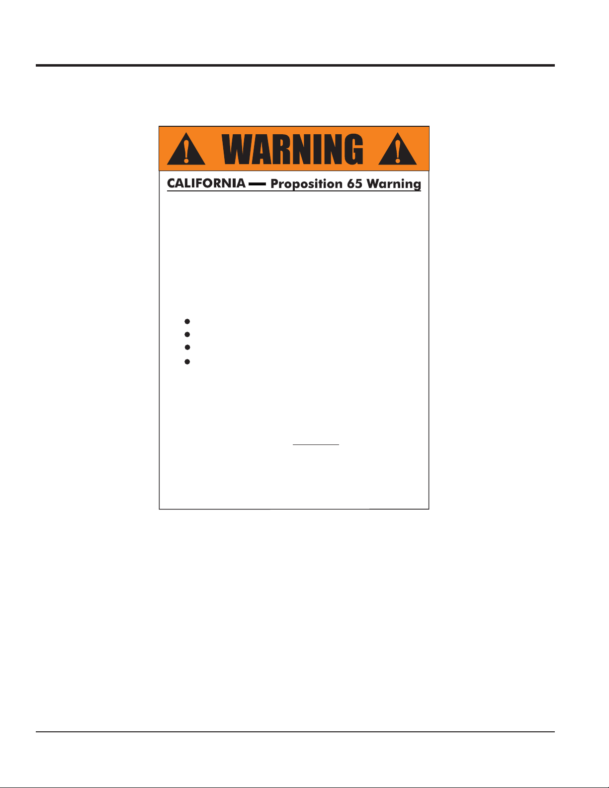
PROPOSITION 65 WARNING
Engine exhaust and some of
its constituents, and some dust created
by power sanding, sawing, grinding,
drillingandotherconstructionactivities
contains chemicals known to the State
of California to cause cancer, birth
defects and other reproductive harm.
Some examples of these chemicals are:
Leadfromlead-basedpaints.
Crystallinesilicafrombricks.
Cementandothermasonryproducts.
Arsenicandchromiumfrom chemically
treatedlumber.
Your risk from these exposures varies,
dependingonhowoftenyoudothistype
of work. To reduce your exposure to
these chemicals: work in aALWAYS
well ventilated area, and work with
approved safety equipment, such as
dust masks that are specially designed
to filter out microscopic particles.
PAGE 2 — FCG16HA SAW • OPERATION AND PARTS MANUAL — REV. #1 (03/19/10)
Page 3
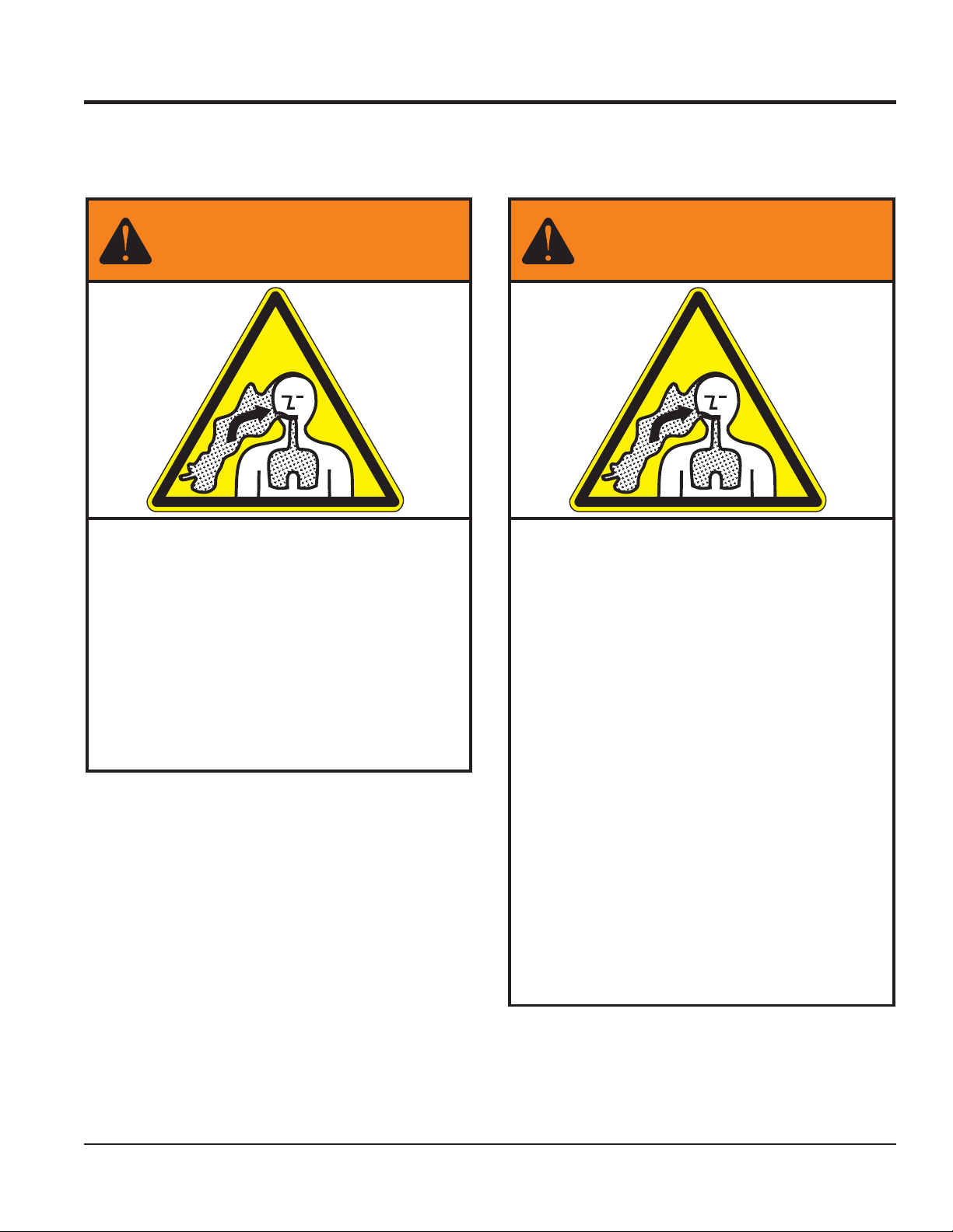
SILICOSIS/RESPIRATORY WARNINGS
WARNING
SILICOSIS WARNING RESPIRATORY HAZARDS
Grinding/cutting/drilling of masonry, concrete, metaland
other materials with silica in their composition may give
off dust or mists containing crystalline silica. Silica is a
basic component of sand, quartz, brick clay, granite and
numerous other minerals and rocks. Repeated and/or
substantial inhalation of airborne crystalline silica can
cause serious or fatal respiratory diseases, including
silicosis. In addition, California and some other
authorities have listed respirable crystalline silica as a
substance known to cause cancer. When cutting such
materials, always follow the respiratory precautions
mentioned above.
WARNING
Grinding/cutting/drilling of masonry, concrete, metaland
other materials can generate dust, mists and fumes
containing chemicals known to cause serious or fatal
injury or illness, such as respiratory disease, cancer,
birth defects or other reproductive harm. If you are
unfamiliar with the risks associated with the particular
process and/or material being cut or the composition of
the tool being used, review the material safety data
sheet and/or consult your employer, the material
manufacturer/supplier, governmental agencies such as
OSHA and NIOSH and other sources on hazardous
materials. California and some other authorities, for
instance, have published lists of substances known to
cause cancer, reproductive toxicity, or other harmful
effects.
Control dust, mist and fumes at the source where
possible. In this regard use good work practices and
follow the recommendations of the manufacturers or
suppliers, OSHA/NIOSH, and occupational and trade
associations. Water should be used for dust
suppression when wet cutting is feasible. When the
hazards from inhalation of dust, mists and fumes cannot
be eliminated, the operator and any bystanders should
always wear a respirator approved by NIOSH/MSHA for
the materials beingused.
FCG16HA SAW • OPERATION AND PARTS MANUAL — REV. #1 (03/19/10) — PAGE 3
Page 4

TABLE OF CONTENTS
FCG16HA SlabSaver
Concrete Saw
Proposition 65 Warning .............................................2
Silicosis/Respiratory Warnings ..................................3
Table Of Contents ..................................................... 4
Specifications ............................................................5
Dimensions ............................................................... 6
Safety Message Alert Symbols ............................. 7-8
Rules For Safe Operation ................................... 9-11
General Information ................................................ 12
Components...................................................... 14-15
Basic Engine ...........................................................16
Guards, Covers And V-Belts ............................. 17-18
Blades ..................................................................... 19
Blade Placement ............................................... 20-22
Inspection ................................................................ 23
Operation .......................................................... 24-27
Maintenance ..................................................... 28-29
Troubleshooting (Saw) ............................................ 30
Troubleshooting (Engine) .................................. 31-32
Explanation Of Code In Remarks Column .............. 34
Suggested Spare Parts ...........................................35
Honda GX200QXC9 Engine
Component Drawings
Specifications and part numbers are subject to
change without notice.
PAGE 4 — FCG16HA SAW • OPERATION AND PARTS MANUAL — REV. #1 (03/19/10)
Page 5

SPECIFICATIONS
Table 1. FCG1 Concrete Saw Specifications
Arbor Size in. (mm) 0.675 In. (15.9 mm)
MAX Blade Width in. (mm) 0.375 In. (9.5 mm)
Blade Capacity in. (mm) 10 In. (254 mm)
Cutting Depth in. (mm)) 3.25 In. (82.6 mm)
Nominal Mass* lbs. (kg) 106 Lb. (48 Kg)
Maximum Operating Mass** lbs. (kg) 113 Lb. (51 Kg)
A-Weighted Sound Pressure Level at Operator's Position 88.3 dB (A)
Guaranteed Sound Power Level 110.0 dB (A)
Hand/Arm Vibration (At Handle)*** 7.14 m/s
* Nominal Mass: Mass without blade, all fluid tanks empty, any optional parts removed.
** Maximum Operating Mass: Includes blade, all fluid tanks full, any necessary components installed.
*** Hand/Arm Vibration (at handle) results with FCG16HA Saw cutting cured concrete at a depth of 1/2" (12.7 mm) with
a 10" (254 mm) blade at FULL THROTTLE.
Table 2. Specifications (Engine)
Model Honda GX200UQXC9
Type
Bore X Stroke
Displacement 12.0 cu-in. (196 cc)
Max Output
Engine
Fuel Tank Capacity
Fuel
Lube Oil Capacity 0.63 US qt (0.60 liter)
Speed Control Method Centrifugal Fly-weight Type
Starting Method Recoil Start
Dimension (L x W x H)
Dry Net Weight 35.3 lbs (16 Kg)
Air-cooled 4 stroke, Single Cylinder, OHV, Gasoline
Engine
2.7 in. X 2.1 in.
(68 mm x 54 mm)
Net H.P. 5.5/3600 R.P.M.
(4.1 kW, 6.5 PS)
Approx. 0.95 US Gallons
(3.6 Liters)
Unleaded Automobile Gasoline
86 Octane or higher
12.3 x 14.8 x 13.2 in.
(313 x 376 x 335 mm)
FCG16HA SAW • OPERATION AND PARTS MANUAL — REV. #1 (03/19/10) — PAGE 5
Page 6
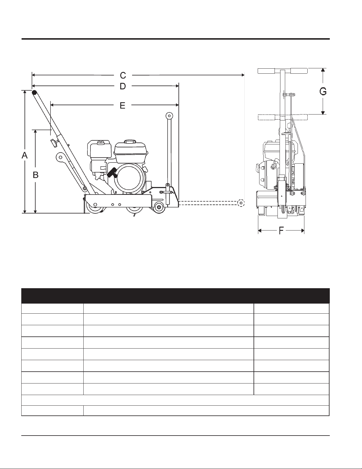
DIMENSIONS
A
B
C
D
E
F
G
Side View
Front View
Figure 1. FCG16HA Concrete Saw Dimensions
Table 3. Dimensions
RETTELECNEREFER NOITPIRCSED )MC(NOISNEMID
)desiaRylluFsraBeldnaH(thgieHxaM
)derewoLylluFsraBeldnaH(thgieHxaM
)derewoLretnioPtnorF&desiaRylluFsraBeldnaH(htgneLxaM
)desiaRretnioPtnorF&desiaRylluFsraBeldnaH(htgneLxaM ).nI84(MC9.121
)desiaRretnioPtnorF&derewoLylluFsraBeldnaH(htgneLxaM ).nI93(MC99
htdiWllarevOxaM ).nI5.31(MC3.43
noitcelfeDraBeldnaHxaM ).nI57.41(MC5.73
snoisnemiDwaSetercnoC1GCF.3elbaT
).nI57.64(MC7.811
).nI0.23(MC3.18
).nI86(MC7.271
)HxWxL(noisnemiDdetarC ).nI32x.nI5.31x.nI5.43(MC4.85xMC3.43xMC6.78
PAGE 6 — FCG16HA SAW • OPERATION AND PARTS MANUAL — REV. #1 (03/19/10)
Page 7
SAFETY MESSAGE ALERT SYMBOLS
FOR YOUR SAFETY AND THE SAFETY OF OTHERS!
Safety precautions should be followed at all times when
operating this equipment. Failure to read, understand and
comply with the Safety Messages and Operating Instructions
could result in injury to yourself and others.
This Owner's Manual has been developed to
provide instructions for the safe and efficient
operation of the FCG16HA Concrete Saw.
For engine maintenance information, please
refer to the engine manufacturer's instructions
for data relative to its safe operation.
Before using this Concrete Saw, ensure that the operating
individual has read, understands, and complies with all
instructions in this manual.
HAZARD SYMBOLS
SAFETY MESSAGE ALERT SYMBOLS
The three (3) Safety Messages shown below will inform you
about potential hazards that could injure you or others. The
Safety Messages specifically address the level of exposure to
the operator, and are preceded by one of three words: DANGER,
WARNING, or CAUTION.
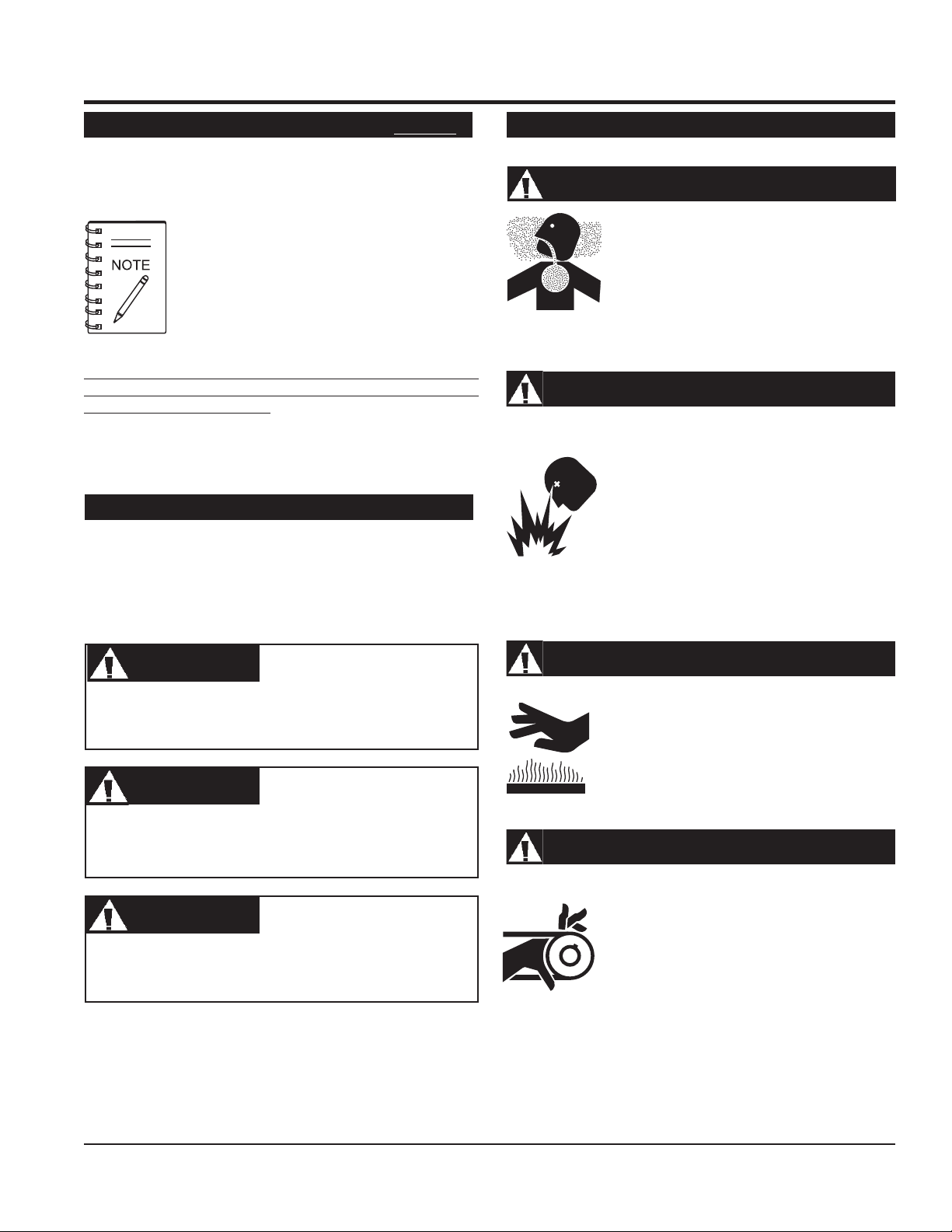
Lethal Exhaust Gases
Engine exhaust gases contain poisonous
carbon monoxide. This gas is colorless and
odorless, and can cause death if inhaled.
NEVER operate this equipment in a confined
area or enclosed structure that does not
provide ample free flow air.
Explosive Fuel
Gasoline is extremely flammable, and its
vapors can cause an explosion if ignited.
DO NOT start the engine near spilled fuel or
combustible fluids. DO NOT fill the fuel tank
while the engine is running or hot. DO NOT
overfill tank, since spilled fuel could ignite if it
comes into contact with hot engine parts or
sparks from the ignition system. Store fuel in
approved containers, in well-ventilated areas
and away from sparks and flames. NEVER
use fuel as a cleaning agent.
DANGERDANGER
DANGER
DANGERDANGER
You WILL be
if you DO NOT follow these directions.
WARNINGWARNING
WARNING
WARNINGWARNING
You CAN be KILLED or
you DO NOT follow these directions.
CAUTICAUTI
CAUTION
CAUTICAUTI
You CAN be
these directions.
Potential hazards associated with FCG16HA Concrete Saw
operation will be referenced with Hazard Symbols which appear
throughout this manual, and will be referenced in conjunction
with Safety Message Alert Symbols.
KILLED
INJURED
or
SERIOUSLY INJURED
SERIOUSLY INJURED
if you DO NOT follow
if
Burn Hazards
Engine components can generate extreme heat.
To prevent burns, DO NOT touch these areas
while the engine is running or immediately after
operations. NEVER operate the engine with
heat shields or heat guards removed.
Rotating Parts
NEVER operate equipment with covers, or
guards removed. Keep fingers, hands, hair
and clothing away from all moving parts to
prevent injury.
FCG16HA SAW • OPERATION AND PARTS MANUAL — REV. #1 (03/19/10) — PAGE 7
Page 8
SAFETY MESSAGE ALERT SYMBOLS
Accidental Starting
ALWAYS place the ON/OFF switch in the OFF
position, when the saw is not in use.
Over Speed Conditions
NEVER tamper with the factory settings of the
engine governor. Personal injury and damage
to the engine or equipment can result if
operating in speed ranges above maximum
allowable.
Guards and Covers In Place
NEVER operate the saw without blade guards
and covers in place. Adhere to safety guidelines
or other applicable local regulations.
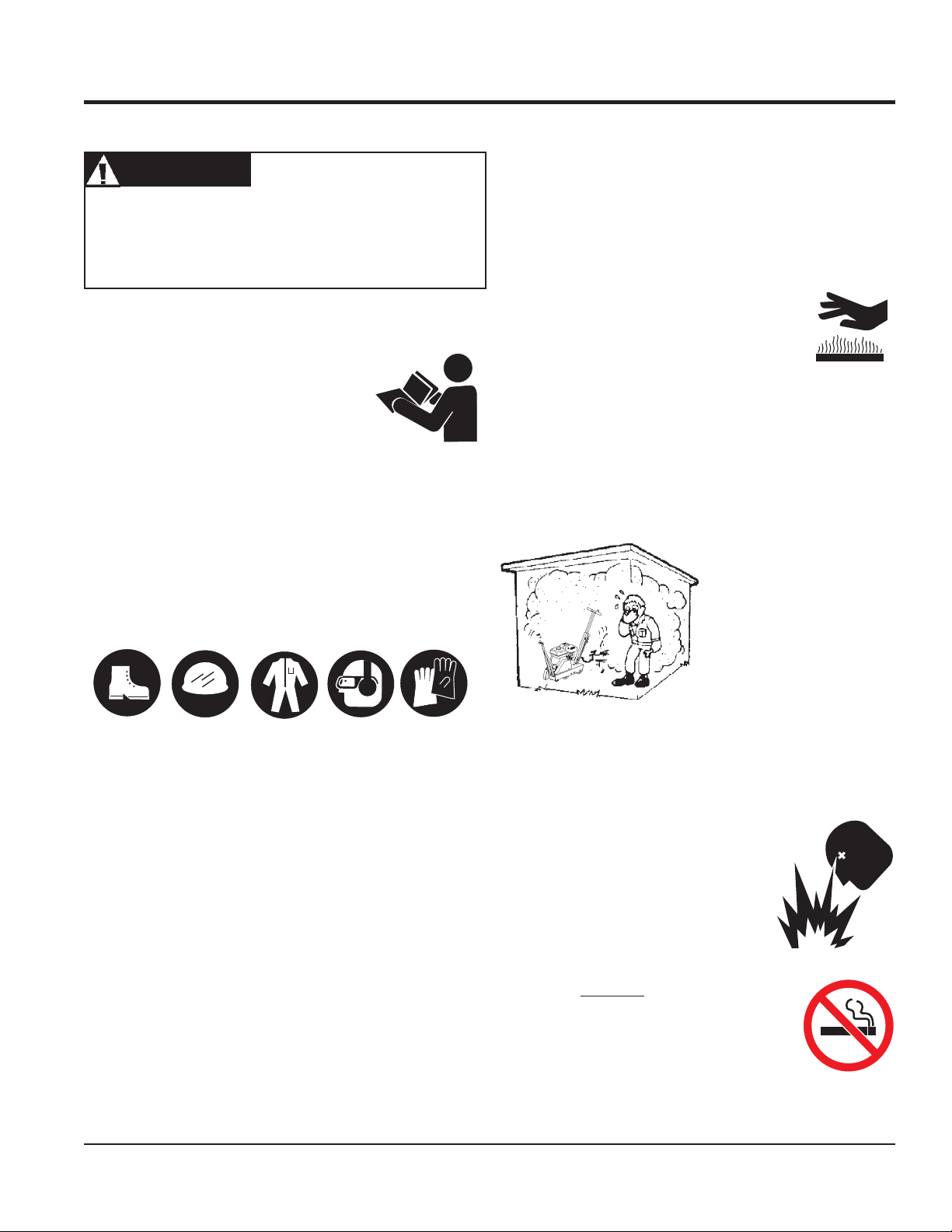
Respiratory Hazard
ALWAYS wear approved respiratory protection.
Sight and Hearing hazard
ALWAYS wear approved eye and hearing
protection.
Equipment Damage Messages
Other important messages are provided throughout this manual
to help prevent damage to your slab saw, other property, or the
surrounding environment.
CAUTICAUTI
CAUTION
CAUTICAUTI
This concrete saw, other property, or the
surrounding environment could be damaged
if you do not follow instructions.
PAGE 8 — FCG16HA SAW • OPERATION AND PARTS MANUAL — REV. #1 (03/19/10)
Page 9
RULES FOR SAFE OPERATION
WARNINGWARNING
WARNING
WARNINGWARNING
Failure to follow instructions in this manual may lead to serious
injury or even death! This equipment is to be operated by
trained and qualified personnel only! This equipment is for
industrial use only.
RULES FOR SAFE OPERATION
■
NEVER operate this equipment when not feeling well due to
fatigue, illness or taking medicine.
■
NEVER operate the saw under the influence or drugs or
alcohol.
■
Replace nameplate, operation and safety decals when they
become difficult to read.
■
ALWAYS check the saw for loosened hardware such as
nuts and bolts before starting.
The following safety guidelines should always be used when
operating the FCG16HA Saw.
SAFETY
■
DO NOT operate or service this equipment
before reading this entire manual. The
manual must be kept available and accessible
to the operator.
■
This equipment should not be operated by persons under the
minimum statutory age limit.
■
NEVER use this machine for any purpose other than those
described in this manual.
■
NEVER operate the saw without proper protective clothing,
shatterproof glasses, steel-toed boots and other protective
devices required for the job.
■
NEVER touch the hot exhaust manifold, muffler
or cylinder. Allow these parts to cool before
servicing the saw.
■
High Temperatures – Allow the engine to cool before adding
fuel or performing service and maintenance functions.
Contact with
■
The engine of this saw requires an adequate free flow of
cooling air. NEVER operate the saw in any enclosed or
■
ALWAYS refuel in a well-ventilated area, away from sparks
and open flames.
hot!
components can cause serious burns.
narrow area where free flow
of the air is restricted. If the
air flow is restricted it will
cause serious damage to the
saw's engine and may cause
injury to people. Remember
the saw's engine gives off
DEADLY
gas.
carbon monoxide
■
■
■
NEVER use accessories or attachments which are not
recommended by Multiquip for this equipment. Damage to
the equipment and/or injury to user may result.
■
Manufacturer does not assume responsibility for any accident
due to equipment modifications. Unauthorized equipment
modification will void all warranties. Any modification which
could lead to a change in the original characteristics of the
machine should be made only by the manufacturer who shall
confirm that the machine is in conformity with appropriate
safety regulations.
■
■
■
FCG16HA SAW • OPERATION AND PARTS MANUAL — REV. #1 (03/19/10) — PAGE 9
ALWAYS use extreme caution when working with flammable
liquids. When refueling, STOP the engine and allow it to
cool.
NEVER operate the saw in an
explosive atmosphere where fumes
are present, or near combustible
materials. An explosion or fire could
result in severe
death.
NEVER
machine. Fire or explosion could result
fuel vapors
from
hot!
engine.
Topping-off to filler port is dangerous, as it tends to spill fuel.
NEVER use fuel as a cleaning agent.
bodily harm or even
smoke
around or near the
, or if fuel is spilled on a
Page 10
RULES FOR SAFE OPERATION
General Safety
■
ALWAYS read, understand, and follow procedures in
Operator's Manual before attempting to operate equipment.
■
ALWAYS be sure the operator is familiar with proper safety
precautions and operating techniques before using the saw.
■
NEVER leave the machine
■
Apply the brakes when leaving or when using on a slope.
■
Maintain this equipment in a safe operating condition at all
times.
■
ALWAYS stop the engine before servicing, adding fuel and
oil.
■
NEVER run the engine without the air filter. Severe engine
damage could occur.
■
ALWAYS service air cleaner frequently to prevent carburetor
malfunction.
■
AVOID wearing jewelry or loose fitting clothing that may snag
on the controls or moving parts, this can cause a serious
injury.
■
ALWAYS keep clear of
saw is in operation.
unattended
rotating
or
while running.
moving parts
while the
Diamond Blade Safety
■
■
■
■
Use appropriate steel centered diamond blades
manufactured for use on concrete saws. See further blade
information on pages 21 through 23.
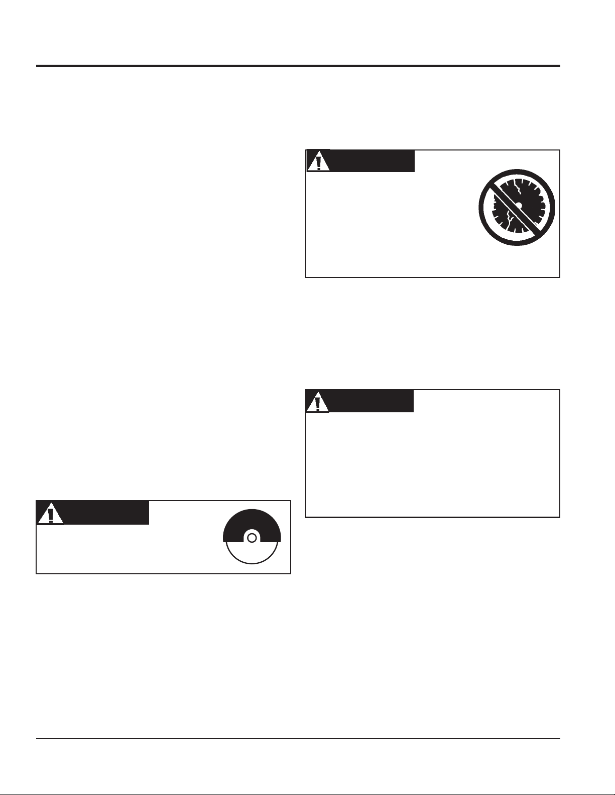
WARNINGWARNING
WARNING
WARNINGWARNING
ALWAYS inspect diamond blades
before each use. The blade should
exhibit no cracks, dings, or flaws in the
steel centered core and/or rim. Center
(arbor) hole must be undamaged and
true. All damaged blades must be
discarded.
Examine blade flanges for damage and excessive wear.
Ensure the cleanliness of the blade before blade is installed.
Blade should fit snugly on the shaft and against the inside/
outside blade flanges.
Ensure the blade is marked with an operating speed greater
than the spindle speed of the saw.
■
ALWAYS store equipment properly when it is not being used.
Equipment should be stored in a clean, dry location out of
the reach of children.
■
ALWAYS keep the work area well organized.
■
ALWAYS Clear the cutting area of any debris, tools, etc. that
would constitute a hazard while the saw is in operation.
WARNINGWARNING
WARNING
WARNINGWARNING
ALWAYS check to make sure that the
operating area is clear before starting the
engine.
■
No one other than the operator is to be in the working area
when the saw is in operation.
■
Always observe all applicable compulsory regulations
relevant to environmental protection, especially, fuel storage,
the handling of hazardous substances, and the wearing of
protective clothing and equipment. Instruct the user as
necessary, or, as the user, request this information and
training.
■
■
■
■
■
WARNINGWARNING
WARNING
WARNINGWARNING
Only cut the material that is specified for the diamond blade.
Read the specifications of the diamond blade to ensure
the proper tool has been matched to the material being cut.
The saw has been engineered for DRY CUTTING. Ensure
a DRY CUTTING blade is being used.
ALWAYS keep blade guards in place. Exposure of the
diamond blade must not exceed 180 degrees.
Ensure that the diamond blade does not come into contact
with the ground or surface during transportation. DO NOT
drop the diamond blade on ground or surface.
The engine governor is set to regulate maximum engine
speed in a no-load condition. Do not tamper with the engine
governor to increase the speed. Increasing the engine speed
could allow the maximum rated spindle speed to be
exceeded, creating an unsafe condition.
Ensure that the blade is mounted for proper operating
direction. (See Figure 12)
Adhere to the Blade Manufacturer's recommendations on
handling, storage, and safe usage of blades.
PAGE 10 — FCG16HA SAW • OPERATION AND PARTS MANUAL — REV. #1 (03/19/10)
Page 11
RULES FOR SAFE OPERATION
Maintenance Safety
NEVER lubricate components or attempt service on a
running machine.
ALWAYS allow the machine a proper amount of time to
cool before servicing.
Keep the machinery in proper running condition.
Fix damage to the machine immediately and ALWAYS
replace broken parts.
Dispose of hazardous waste properly. Examples of
potentially hazardous waste are used motor oil, fuel and
fuel filters.
DO NOT use food or plastic containers to dispose of
hazardous waste.
Saw Transportation Safety
■
DO NOT use the handle bars and/or front pointer as lifting
points.
■
ALWAYS use ramps capable of supporting the weight of the
saw and the operator to load and unload the saw.
■
If the saw must be lifted, use the lifting bale and a crane or
forklift with a rated lifting capacity for the saw. Never attempt
to lift the saw by yourself.
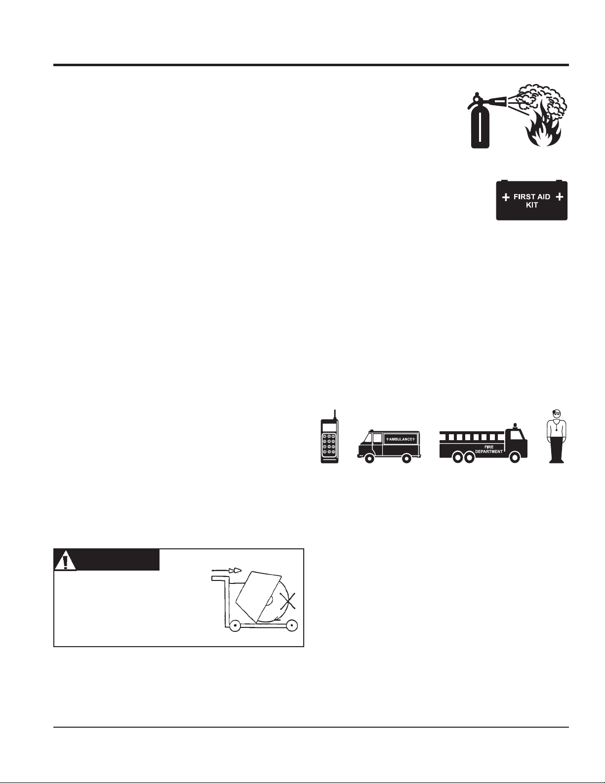
Emergencies
ALWAYS know the location of
the nearest
ALWAYS know the location of the
nearest
In emergencies ALWAYS
phone or
phone numbers of the nearest
fire department
in the case of an emergency and could keep a serious
situation from becoming a tragic one.
fire extinguisher
first aid kit
keep a phone on the job site
.
. Knowing this information is invaluable
.
know the location of the nearest
. Also know the
ambulance, doctor
and
■
When transporting the saw, place the saw directly inside
towing vehicle truck-bed or onto trailer and tie-down securely.
■
NEVER attempt to tow the untrailered saw behind a vehicle.
■
DO NOT use on slopes or on extremely uneven surfaces.
■
NEVER tip the engine to extreme angles as it may cause oil
to gravitate into the cylinder head making the engine start
difficult.
■
NEVER load, unload, or transport the saw with the blade
mounted.
WARNINGWARNING
WARNING
WARNINGWARNING
All displacement of the machine
outside the cutting area shall be
carried out with the tool not in
rotation.
FCG16HA SAW • OPERATION AND PARTS MANUAL — REV. #1 (03/19/10) — PAGE 11
Page 12

GENERAL INFORMATION
Intended Use
Operate the FCG16HA Saw, tools and components in
accordance with the manufacturer's instructions. Use of any
other tools for stated operation is considered contrary to
designated use. The risk of such use lies entirely with the user.
The manufacturer cannot be held liable for damages as a result
of misuse.
This saw is not intended for wet cutting. (The use of water sprayed
onto the tool [blade] during the cutting operation).
FAMILIARIZATION
This FCG16HA Saw is designed for dry sawing of concrete
slabs utilizing diamond blades. The saw has been engineered
for general and industrial flat sawing applications that include:
Joint Sawing of Green Concrete, Decorative Sawing in Cured
Concrete, Light Demolition Sawing and "V" Groove
Beveling. The simple and compact nature of the FCG16HA
makes it a perfect sawing tool for one person to operate and
transport. The saw combines innovative features, top quality
components, and a committed attention to state-of-the-art
manufacturing.
For peak performance, the FCG16HA has been engineered to
operate a powerful GX200 Honda Gasoline engine and 10"
diameter diamond blades. This special design allows for fast/
clean cuts in different materials at depths from 1/4" to 3 1/4".
Heavy-duty front and rear axles, polyurethane wheels with
permanently sealed ball bearings, and solid undercarraige
assembly provide years of reliable use. The FCG16HA
incorporates an innovative PosiLok raise/lower control assembly
that provides fingertip control of blade orientation, infinitely
adjustable locking blade depth control, and depth feed gauge.
Retractable front & rear pointers with "tracking wheels" are
provided to support precise straight sawing. This system permits
the operator to quickly adjust the blade cutting depth and
safeguard against "blade-creep" during sawing operations. For
operator comfort and ease of transportation & storage, an
adjustable locking handle bar is provided.
Operator control of the saws is safely accomplished with
adjustable handle bars, and a conveniently oriented raise/lower
lever and depth adjustment wheel. An engine-off switch (Item 22
Fig. 3) located next to the handle lock allows the operator to
safely turn the engine off from the operator's position and away
from moving parts.
ENGINE
Refer to the engine Owner’s Manual for specific instructions
regarding operation, service and maintenance.
The jig-welded reinforced heavy gauge steel frame and chassis
assembly are designed to eliminate operational bending and/or
flex that would lead to diminished blade performance. Also, the
frame's general weight-to-strength ratio and center mounted
blade design ensure accurate tracking in the cut.
A robust blade shaft bearing assembly ensures minimal flutter
and shaft harmonics providing the most advantageous
conditions for a diamond blade at operating speeds.
PAGE 12 — FCG16HA SAW • OPERATION AND PARTS MANUAL — REV. #1 (03/19/10)
Page 13

NOTES
FCG16HA SAW • OPERATION AND PARTS MANUAL — REV. #1 (03/19/10) — PAGE 13
Page 14
CONTROLS & COMPONENTS
COMPONENTS
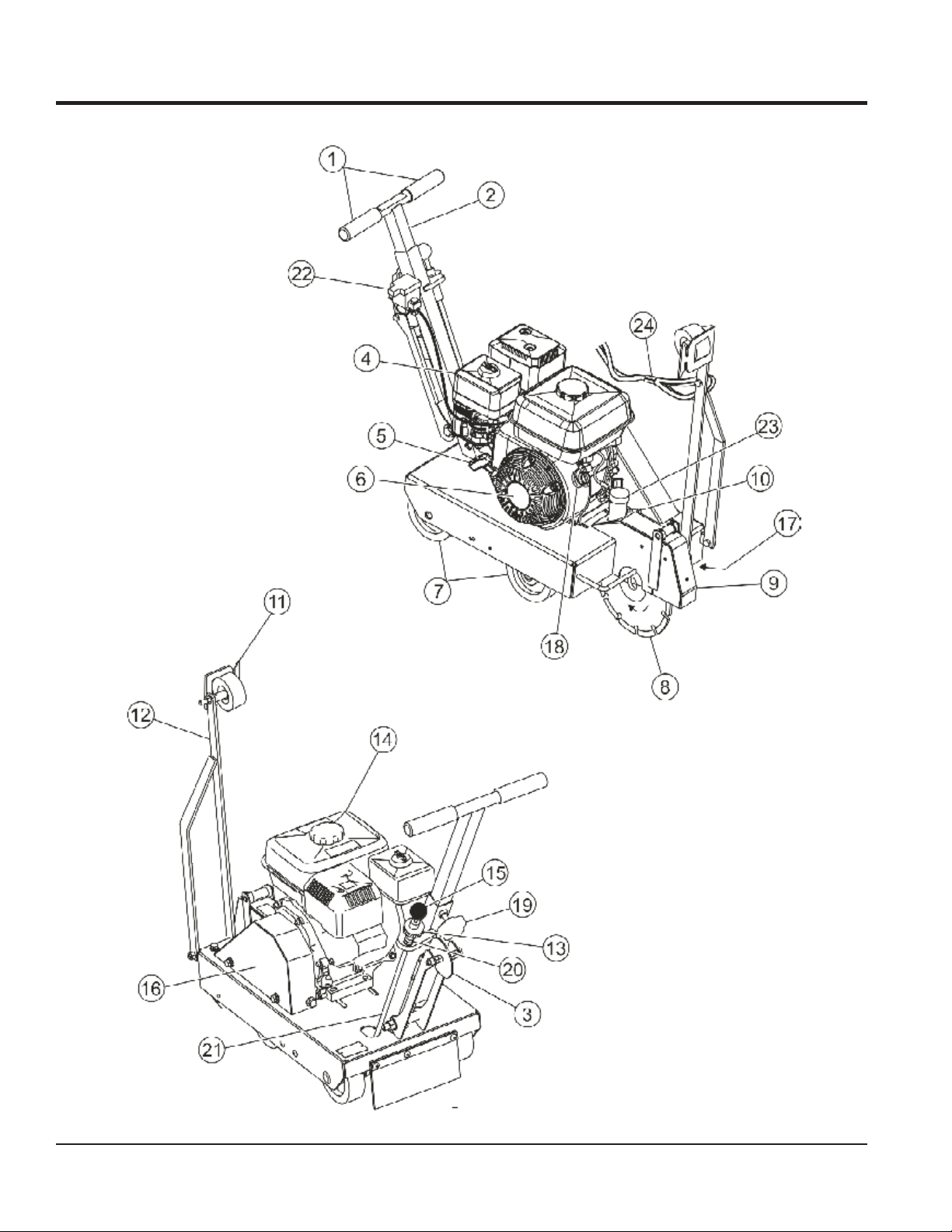
Figure 3. FCG16HA Concrete Saw
PAGE 14 — FCG16HA SAW • OPERATION AND PARTS MANUAL — REV. #1 (03/19/10)
Page 15

COMPONENTS
Figures 3 shows the location of the basic controls or components,
for the FCG16HA Concrete Saw. Listed below is a brief
explanation of each control or component
1. Hand Grips/Handlebar – When operating the saw, place
both hands on each grip to maneuver the saw.
2. Adjustable Handle – Set to comfortable operating position.
3. Rear Guide – Rear guide wheel drops into cut to assist in
straight tracking.
4. Air Filter – Prevents dirt and debris from entering the engine
air intake. Keep cleaned and replace when necessary.
5. Recoil Starter Handle – Pull to engage and start the
engine.
6. Recoil Starter Assembly – Engages the engine when
the handle is pulled and rewinds the starter rope when the
handle is released.
7. Wheels/Carraige Assembly – Heavy-duty polyurethane
wheels with permanently sealed ball bearings.
8. Diamond Blade – 0.675" (15.9 mm) Arbor diameter. 10"
blade capacity. 10" diameter provides for 1/4" to 3 1/4"
depth of cut. MAX Width blade is .375" (9.5 mm).
20. Screw Plunger – Line up bottom edge of Depth Stop Rod
on Screw Plunger across from desired depth line mark.
21. Depth Stop Rod – Holds blade above working surface or
allows blade to cut into working surface at specified depth.
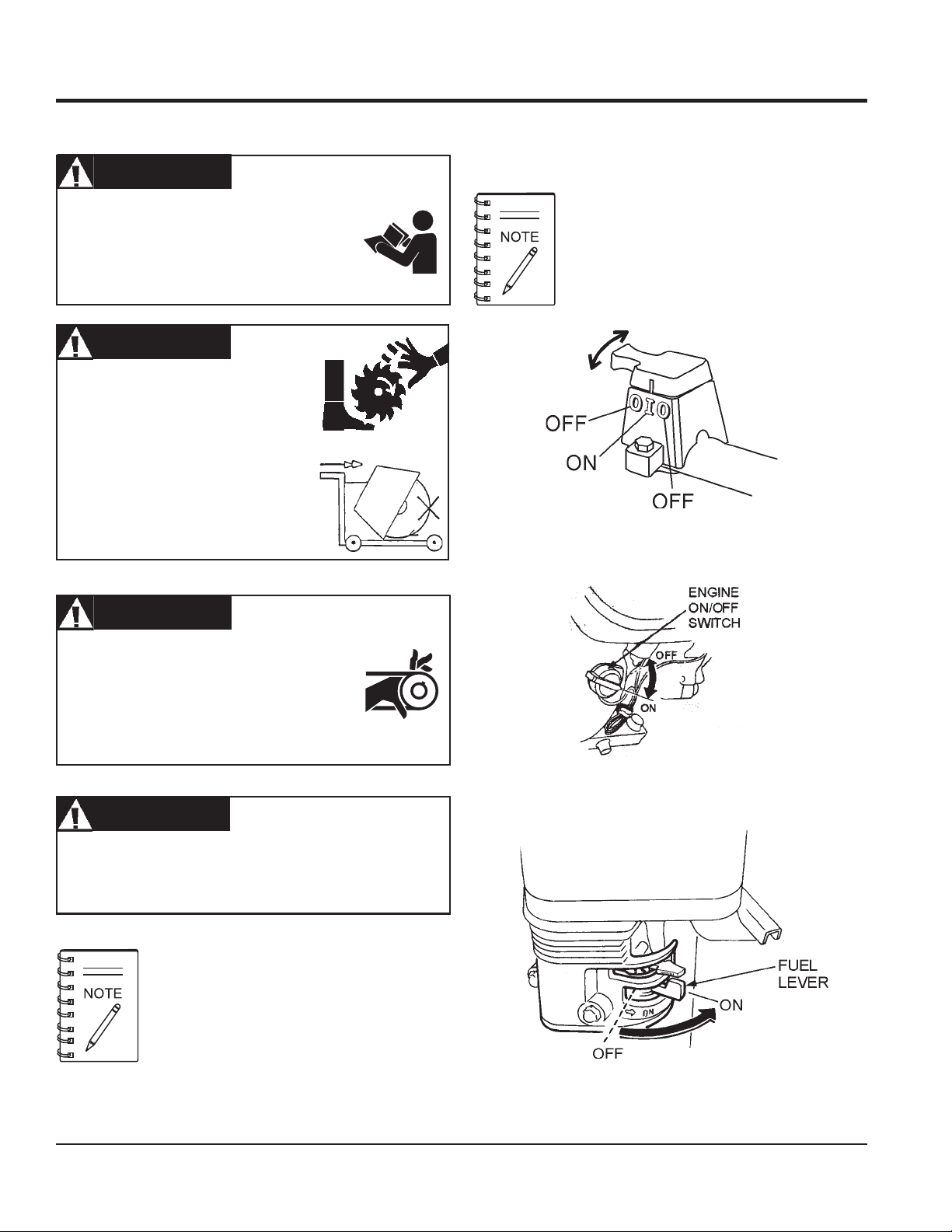
22. Engine Shut-off Switch – The Engine Shutdown Switch
located next to the handle lock serves both as an Emergency
Engine Shut-Off and as the primary Shutdown switch. This
allows the operator to shutdown the saw safely away from
moving parts.
23. Dust Collection – Provides for connection to suitable dust
collection bag or vacuum system.
24. Sash – Allows for the lowering and raising of the front
guide from the operator's position.
9. Blade Guard – Covers saw blade and flips up to allow
blade to be changed.
10. Belt Tension Adjuster – Adjusts belt tension.
11. Front Pointer – Assists in straight tracking.
12. Front Pointer Arm – Pivots up for storage and pivots down
for use.
13. Depth Adjust Disk – Turn disk clockwise or counterclockwise to adjust the cutting depth up or down.
14. Fuel Tank – Use unleaded gasoline. Do not overfill.
15. Shift Knob – Moves Depth Stop Rod in or out of keyhole
slot.
16. V-Belt Cover – Remove this cover to gain access to the Vbelt. NEVER operate the saw with this cover removed.
17. Arbor Shaft Grease Zerks – Conveniently located for
lubrication.
18. On/Off Switch (Engine)– Turn to the "ON" position to
allow engine to be started and turn to the "OFF" position to
prevent accidental starting.
19. Handle Lock – Lock handle height to a comfortable
operating position.
FCG16HA SAW • OPERATION AND PARTS MANUAL — REV. #1 (03/19/10) — PAGE 15
Page 16
BASIC ENGINE
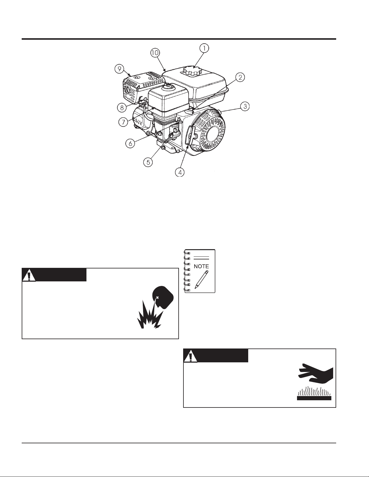
Figure 4. Engine Controls and Components
INITIAL SERVICING
The engine (Figure 4) must be checked for proper lubrication and
filled with fuel prior to operation. Refer to the manufacturers engine
manual for instructions & details of operation and servicing.
1. Fuel Filler Cap – Remove this cap to add unleaded
gasoline to the fuel tank. Make sure cap is tightened
securely. DO NOT over fill.
DANGERDANGER
DANGER
DANGERDANGER
Adding fuel to the tank should be done only
when the engine is stopped and has had an
opportunity to cool down. In the event of a fuel
spill, DO NOT attempt to start the engine until
the fuel residue has been completely wiped up,
and the area surrounding the engine is dry.
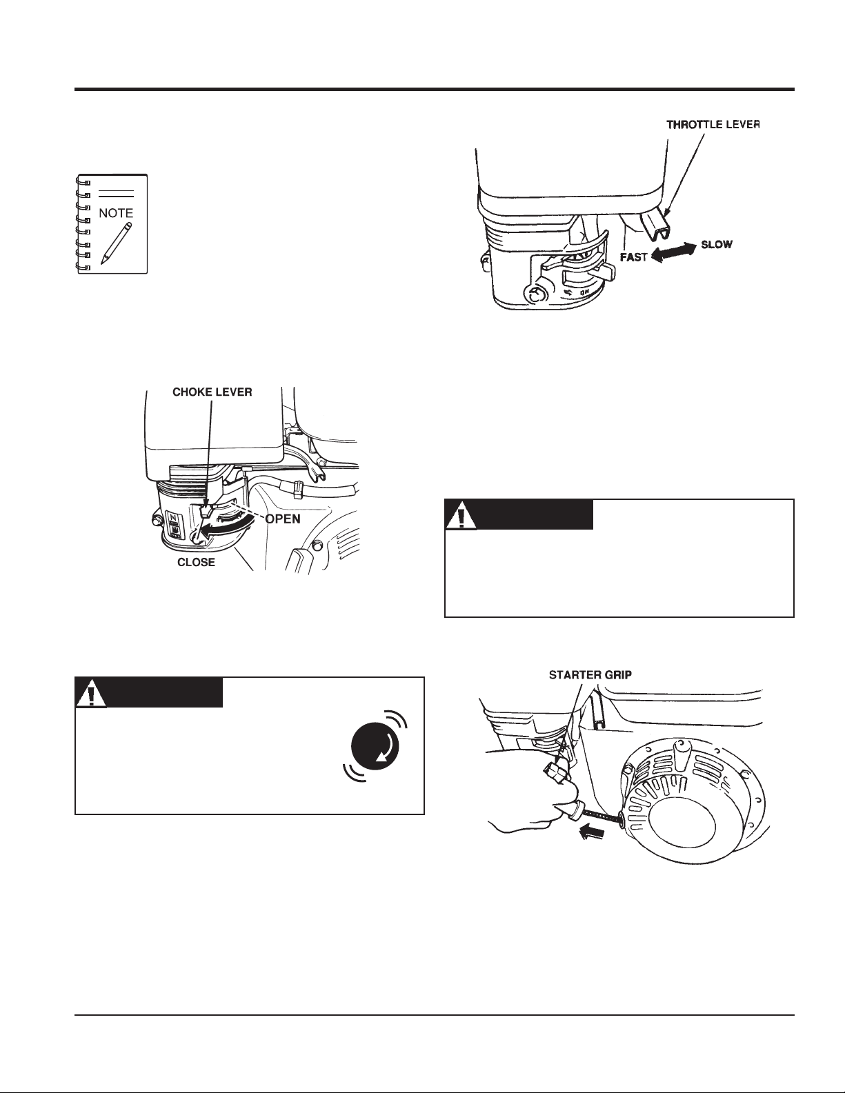
2. Throttle Lever – Used to adjust engine RPM speed (lever
advanced forward
FAST
).
3. Engine ON/OFF Switch – ON position permits engine
starting, OFF position stops engine operations.
4. Recoil Starter (pull rope) – Manual-starting method. Pull
the starter grip until resistance is felt, then pull briskly and
smoothly.
5. Fuel Valve Lever – OPEN to let fuel flow, CLOSE to stop
the flow of fuel.
SLOW
, lever back toward operator
6. Choke Lever – Used in the starting of a cold engine, or in
cold weather conditions. The choke enriches the fuel
mixture.
7. Air Cleaner – Prevents dirt and other debris from entering
the fuel system. Remove wing-nut on top of air filter
8. Spark Plug – Provides spark to the ignition system. Clean
spark plug once a week.
9. Muffler – Used to reduce noise and emissions.
WARNINGWARNING
WARNING
WARNINGWARNING
Engine components can generate extreme heat.
To prevent burns, DO NOT touch these areas
while the engine is running or immediately after
operating. NEVER operate the engine with the
muffler removed.
10. Fuel Tank – Holds unleaded gasoline. For additional
information refer to engine owner's manual.
cannister to gain access to filter element.
Operating the engine without an air filter, with a
damaged air filter, or a filter in need of
replacement will allow dirt to enter the engine,
causing rapid engine wear.
PAGE 16 — FCG16HA SAW • OPERATION AND PARTS MANUAL — REV. #1 (03/19/10)
Page 17
WARNINGWARNING
WARNING
WARNINGWARNING
NEVER operate the saw without blade
guards and covers in place. DO NOT
operate with the front of the blade guard
raised. The blade exposure cannot exceed
180 degrees during operation. Adhere to
the safety guidelines of the American
National Standards Institute (ANSI)
B7.1 and B7.5.
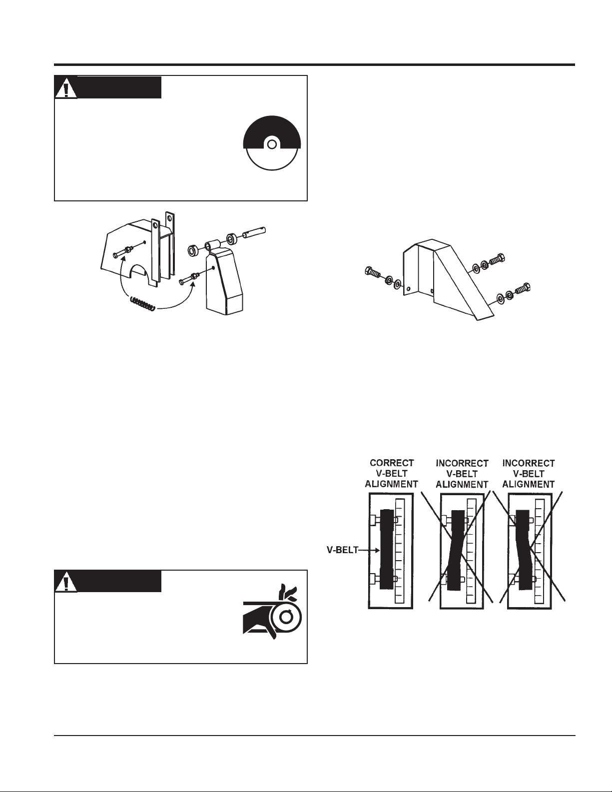
Figure 5. Blade Guard
GUARDS, COVERS AND V-BELTS
V-belt Alignment and Tensioning
This concrete saw is equipped with a premium V-belt that has
been aligned and tensioned by factory personnel. The V-belt
must be aligned and tensioned for proper operation of the saw.
Use the following procedure to check the alignment of V-belt:
1. Remove the bolts that secure the V-belt cover (Figure 6) to
the saw frame.
Figure 6. V-Belt Cover
CHECK the following on the"blade guard" (Figure 5):
■
Ensure the capacity of the blade guard matches the diameter
of your diamond blade.
■
Check that the guard is bolted firmly upon the saw frame.
■
Check that the spring tensioned front cover of the guard is
firmly seated with the rear section of the guard, and there are
no gaps. NEVER lift the blade guard while cutting.
V-belt Check
A worn or damaged V-belt can adversely affect the performance
of the saw. If the V-belt is defective or worn, replace and the V-belt
as outlined on page 20.
CAUTIONCAUTION
CAUTION
CAUTIONCAUTION
NEVER attempt to check the V-belt with the
engine running. Severe injury can occur.
Keep fingers, hands, hair and clothing
away from all moving parts.
2. Check uniform parallelism (Figure 7) of V-belt and pulley
(sheaves). Use a straight-edge or machinist's square against
both pulleys and adjust both pulleys until equally aligned.
Figure 7. Pulley Alignment
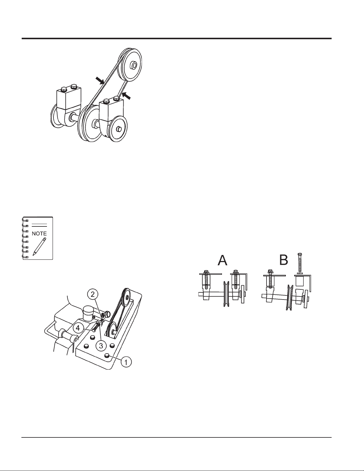
3. Check V-belt tension by using a tension meter (6.0 - 9.0 lbs.)
against the inside belt at a mid point between the two pulleys,
or by deflecting the center belt at a mid point 3/8" (10 mm) to
1/2" (13 mm). See Figure 8.
FCG16HA SAW • OPERATION AND PARTS MANUAL — REV. #1 (03/19/10) — PAGE 17
Page 18
GUARDS, COVERS AND V-BELTS
3. Tighten the adjusting hex screw (4) while holding the engine
in place to maintain pulley alignment. (a screwdriver can be
used as a lever at the rear belt guard mounting boss to hold
the back of the engine while adjusting V-belt tension.)
4. Re-tighten the locking nut (3).
5. With V-belt held in proper alignment, (engine parallel with
the frame), re-tighten the 4 engine mounting hex screws.
Verify that all hex screws are properly tightened.
To Remove and Replace the V-belt:
Figure 8. V-Belt Tension Check
4. DO NOT over or under tighten the V-belt. Severe damage
can occur to the saw and engine crank shaft if the belt is
over-tensioned. A decrease of power to the blade and poor
performance will result if the belt is under-tensioned (loose
on pulleys).
V-belt alignment must be rechecked after
adjusting belt tension.
To Tighten the V-belt:
If the V-belt become worn or damaged, replace it with P/N 16052
(Gates/Optibelt 3VX335).
1. Remove the 3 hex screws holding the V-belt guard and
remove the guard.
2. Loosen the 4 engine mounting hex screws. (item 2, Figure 9)
3. Loosen locking nut on the V-belt tension adjuster (item 3,
Figure 9). Loosen the tension on the V-belt by turning the
tension adjuster hex screw (item 4, Figure 9).
4. Pull the engine ahead to provide slack in the V-belt.
5. Loosen the 4 arbor shaft hex screws, (item 1, Figure 9).
Figure 10. V-Belt Removal
6. Remove the two outer arbor shaft hex screws allowing the
7. Reinstall new V-belt.
8. Re-install and tighten arbor shaft hex head screws.
Figure 9. V-Belt Tension Adjust
1. With V-belt guard removed, loosen the 4 engine mounting
hex screws. (items 2 Figure 9)
2. Loosen locking nut on the V-belt tension adjuster, (3 ).
9. With V-belt held in proper alignment, re-tighten the 4 engine
10. Re-install belt guard with 3 hex screws.
PAGE 18 — FCG16HA SAW • OPERATION AND PARTS MANUAL — REV. #1 (03/19/10)
outside of the shaft to drop, (B in Figure 10), allowing removal
of the V-belt.
mounting hex screws. (Follow V-belt tightening procedures.)
Page 19
BLADES
SPECIFIC TOOLS TO BE USED
This saw is to use tools (blades) as follows:
Steel Core Segmented or Continuous Diamond Rim
Cutting Wheel.
Any other type of tool is not to be used. See Table 4 for specific
blade usage for material.
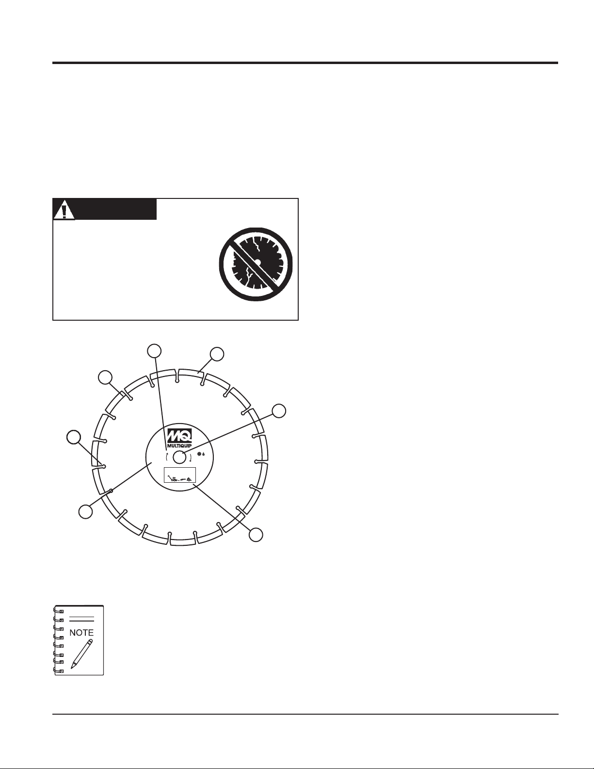
WARNINGWARNING
WARNING
WARNINGWARNING
Failure to thoroughly inspect the
diamond blade (Figure 11) for
operational safety could result in
damage to the blade, the saw, and may
cause injury to the user or others in the
operating area. All damaged blades
must be discarded.
3
4
1. Stress Relief Holes (Gullets) –
Check the steel core for
cracks that may have propagated from the slots and/or
gullets. Cracks indicate extreme fatigue failure and if sawing
continues, catastrophic failure will occur.
2. Edge Of The Steel Core – Check the diameter edge for
discoloration (blue oxidation) indicating an overheating
condition caused by insufficient cooling water/air.
Overheating of blades may lead to loss of core tension
and/or increase the possibility for blade failure. Check to
make sure the steel core’s width is uniform about the rim of
the blade, and not succumbing to an “under cutting”
condition brought about by highly abrasive material or
improper under cutting core protection.
3. Directional Arrow – Check to ensure that the blade is
oriented properly on the blade shaft for sawing. Reference
the directional arrow in the blade and place it so the direction
of rotation “downcuts” with the turn of the shaft.
4. Diamond Segment or Rim – Ensure there are no cracks,
dings, or missing portions of the diamond segment/rim. DO
NOT
use a blade that is missing a segment or a portion
the rim
of
. Damaged and/or missing segments/rims may
cause damage to your saw, and injury to the user or others
in the operating area.
5. Specifications – Ensure that the blade specifications, size,
and diameter properly match up to the sawing operation.
6
Utilizing a diamond blade not matched properly to the task
may result in poor performance and/or blade damage.
1211
MAX
RPM
6,115
Very Soft Material
Model 10PSA
Dry/Wet
Cutting
6. Arbor Hole – It is essential that the arbor hole diameter
properly matches the blade, and that it is free from
distortions. Correct blade flanges (collars) must be used.
The inside face of the flanges must be clean & free of debris.
An out of round arbor condition will cause damage to the
blade and the saw.
7
7. MAX RPM – This RPM reference is the maximum safe
5
operating speed for the blade selected. DO NOT use
blades rated at a lower rotational speed than the rated
RPM of the saw (6000 RPM). Exceeding the MAX RPM is
Figure 11. Diamond Blade
dangerous, and may cause poor performance and may
damage the blade. All blades must be designed to meet or
exceed the maximum spindle RPM.
Adhere to the Blade Manufacturer's
recommendations on handling, storage, and safe
usage of blades.
FCG16HA SAW • OPERATION AND PARTS MANUAL — REV. #1 (03/19/10) — PAGE 19
Page 20
lairetaMedalB
etercnoCderuCedalBetercnoCderuC
BLADE PLACEMENT
noitceleSedalBdnAgnitsiLlairetaM.4elbaT
etercnoCneerGedalBete
tlahpsAedalBtlahpsA
etercnoCrevotlahpsAedalBetercnoC/tlahpsA
seirotcarfeR,yrnosaM,kcirB,kcolBeda
enotS,cimareC,eliTedalBeliT
Diamond Blades
Selecting the diamond blade TYPE and GRADE defines how
the blade will perform both in cutting speed and blade life.
Selection of the proper diamond blade consists of:
Material to be Cut
Type of Saw Being Used
Spindle Speed of Saw
Hardness Characteristics of the Material
Performance Expectations
Factors for sawing economy:
Type of Blade
Depth of Cut
Sawing Speed
Cutting Depth
The FCG16HA Concrete Saw has a capacity for a 10" blade
with an 0.675" (15.9 mm) Arbor diameter. This allows a cutting
range from 0" to 3 1/4".
BLADE PLACEMENT
rcnoCneerG
lByrnosaM
WARNINGWARNING
WARNING
WARNINGWARNING
Failure to thoroughly inspect the diamond
blade for operational safety could result in
damage to the blades or the saw and may
cause injury to the user or others in the
operating area.
D
Characteristics of the Material Being Cut
Refer to Figure 12 for the following components.
Blade Speed
A diamond blade’s performance is directly connected to specific
peripheral (rim) speeds.
The following shaft rotational speeds have been factory set to
ensure optimum blade performance.
FCG16HA - 10” (254 mm)Capacity - 6000 RPM.
WARNINGWARNING
WARNING
WARNINGWARNING
Operating saw blades at rotational speeds
greater than those specified by the manufacturer can cause blade damage, and may injure the user or others in the operating area.
PAGE 20 — FCG16HA SAW • OPERATION AND PARTS MANUAL — REV. #1 (03/19/10)
1. Blade Guard - Pivot the blade guard front cover all the way
back. The guard tension spring will keep the front cover in
position.
2. Blade Hex Nut - Unscrew the blade shaft nut (right side
loosens clockwise and tightens counter-clockwise while the
left side loosens counter-clockwise and tightens clockwise.
DO NOT overtighten the nut (approximately 45-50 ft. lb/6168 N/m) when finalizing the assembly.
3. Outside Blade Flange (Collar) - Ensure that the outside
blade flange is placed flush against the diamond blade.
The inside surface of the flange must be free of debris and
permit a tight closure on the surface of the blade core.
Page 21
4. Diamond Blade - Ensure that the proper diamond blade
has been selected for the job. Pay close attention to the
directional arrows on the blade. The blade's operating
directional arrows must point in a "down-cutting" direction
to perform correctly. When placing the blade onto the blade
shaft, ensure the arbor hole of the blade matches the
diameter of the shaft.
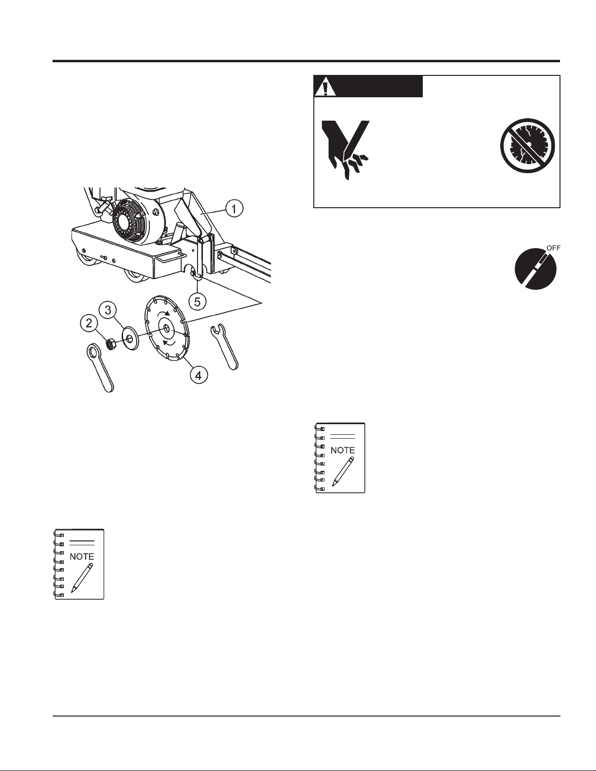
Blade Removal and Replacement
1. Ensure the Engine Shutdown switch (Item 22,
2. Place the FCG16HA Saw on a stable level working surface.
BLADE PLACEMENT
WARNINGWARNING
WARNING
WARNINGWARNING
Dropping or forcing the
blade onto the cutting surface
can severely damage the
diamond blade and may
cause serious damage to the
saw and bodily harm.
Fig.3) and the ON/OFF switch on the engine
are turned to the "OFF" position.
Figure 12. Diamond Blade Placement
5. Inner Flange (Collar) - This flange is fixed upon the blade
shaft. The inside surface of the flange must be free of debris
and permit a tight closure on the surface of the blade.
The following steps should be accomplished
before using the FCG16HA Saw on any cutting
surface.
3. Ensure the blade is raised and the raise/lower rod is locked
into position.
4. Raise the blade by appling a downward pressure on the
handlebars to raise the blade and allow the raise/lower rod
to drop into the "raised-position" slot.
When removing or installing a diamond blade,
please note that the blade retaining nuts are left
and right-hand threaded.
5. Lift up the blade guard cover (item 1 Figure 12) to gain
access to the diamond blade.
6. Use the provided blade nut and blade shaft locking
wrenches (Figure 12) to install the diamond blade.
7. While holding the blade shaft with the locking wrench,
remove the blade hex nut (clockwise direction) and outer
blade flange.
8. Remove the old blade and install a new blade in the same
rotational direction as marked on the blade.
9. Reinstall the outer blade flange and hex nut. Tighten the
nut firmly (counter-clockwise direction). DO NOT OVER
TIGHTEN.
FCG16HA SAW • OPERATION AND PARTS MANUAL — REV. #1 (03/19/10) — PAGE 21
Page 22
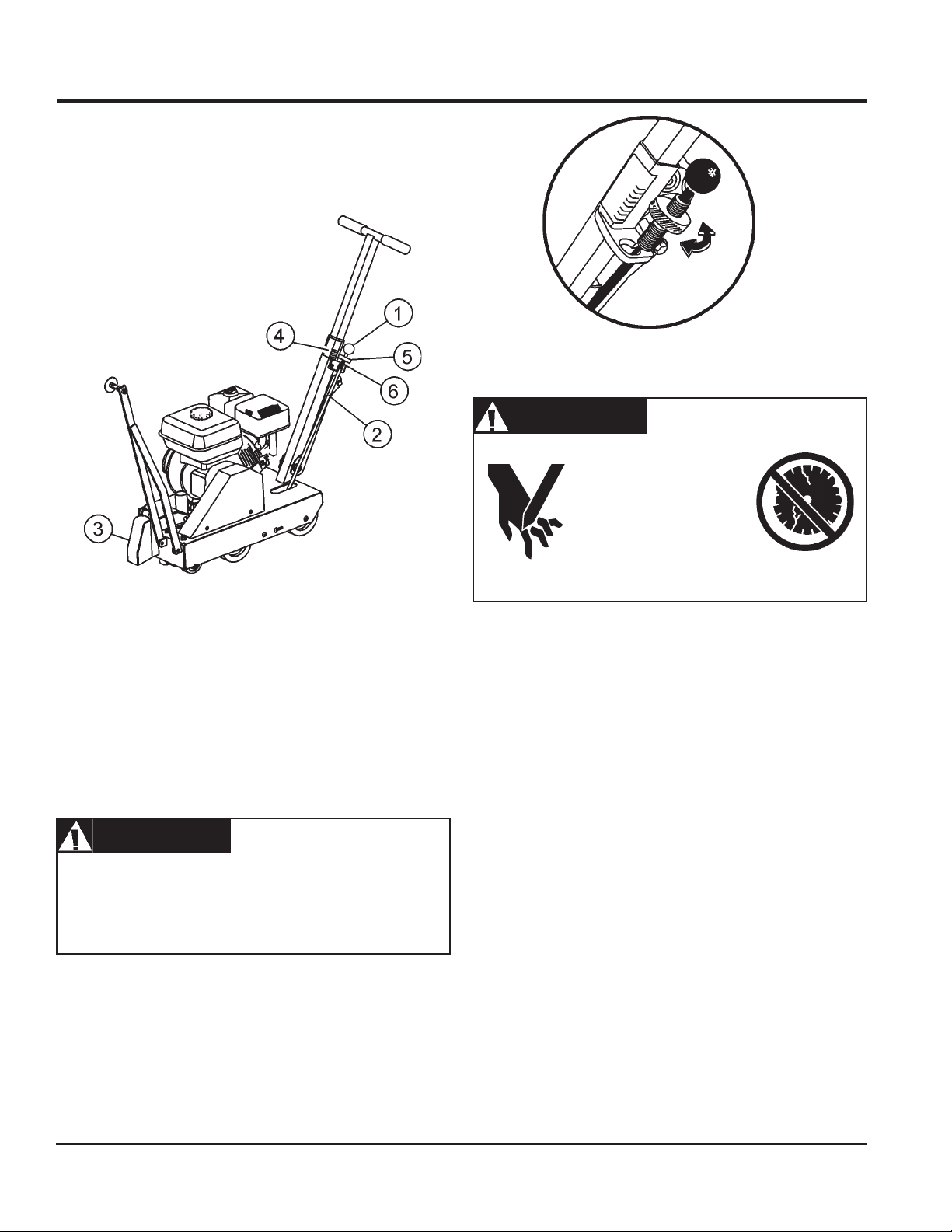
Cutting Depth Adjustment
The FCG16HA Saw is equipped with a Raise/Lower Assembly
that is supported by the following components (Figure 13).
Figure 13. Raise/Lower Assembly
(1) Shift Knob
(2) Depth Stop Rod
(3) Blade Guard
(4) Depth Control Indicator
(5) Depth Adjust Disk
(6) Screw Plunger
To adjust the blade to the desired cutting depth, perform the
following steps:
1. Mount the desired diamond blade on the shaft and secure
as instructed in the Blade Removal and Replacement
section.
2. While holding the handle bars to support the weight of the
saw, grasp the knob of the Depth Stop Rod and move it
forward out of its keyhole slot. (Figure 14)
BLADE PLACEMENT
Figure 14. Raise/Lower Adjustment Wheel
WARNINGWARNING
WARNING
WARNINGWARNING
Dropping or forcing the
blade onto the cutting
surface can severely
damage the diamond
blade and may cause
serious damage to the
saw and bodily harm.
WARNINGWARNING
WARNING
WARNINGWARNING
ALWAYS be certain the Shutdown switch and the engine
ON/OFF switch are in the "OFF" position and the blade
shaft has COMPLETELY STOPPED ROTATING before
performing the following operations.
PAGE 22 — FCG16HA SAW • OPERATION AND PARTS MANUAL — REV. #1 (03/19/10)
3. Gently allow the blade to contact the surface.
4. Rotate the Depth Stop Disk about the Screw Plunger and
line up the bottom edge of the Depth Stop Disk across
from desired depth line mark.. THIS LINE MARK WILL
COINCIDE WITH THE BLADE CUTTING DEPTH
REGARDLESS
5. Press down on the handlebars again to lift the blade until
the Depth Stop Rod drops into the back portion of the
keyhole slot.
6. You are ready to start cutting. Refer to the following preinspection and operation sections.
7. Test the depth of cut by cutting a short distance, then measure
the depth of the cut.
OF BLADE DIAMETER USED.
Page 23

Before Starting
1. Read safety instructions at the beginning of
manual.
INSPECTION
2. Clean the
engine cooling air inlet, carburetor and air cleaner.
3. Check the air filter for dirt and dust. If air filter is dirty, replace
air filter with a new one as required.
4. Check carburetor for external dirt and dust. Clean with dry
compressed air.
5. Check fastening nuts and bolts for tightness.
Engine Oil Check
1. To check the engine oil level, place the saw on secure level
ground with the engine stopped. The frame platform
be level
2. Remove the filler dipstick from the engine oil filler hole
(Figure 15) and wipe it clean.
saw,
removing dirt and dust, particularly the
to accurately check the engine oil.
must
Motor fuels are highly flammable and can be
dangerous if mishandled. DO NOT smoke
while refueling. DO NOT attempt to refuel the
saw if the engine is
Figure 16. Engine Oil Dipstick (Oil Level)
epyTliO.5elbaT
nosaeS erutarepmeT epyTliO
remmuS rehgiHroC°52 03-W01EAS
llaF/gnirpS C°01~C°52 02/03-W01EAS
retniW rewoLroC°0 01-W01EAS
WARNINGWARNING
WARNING
WARNINGWARNING
hot or running
.
1. Remove the gasoline cap located on top of fuel tank.
Figure 15. Engine Oil Dipstick (Removal)
3. Insert and remove the dipstick without screwing it into the filler
neck. Check the oil level shown on the dipstick.
4. If the oil level is low (Figure 16), fill to the edge of the oil filler
hole with the recommended oil type (Table 5).
Reference manufacturer engine manual for
2. Visually inspect to see if fuel level is low. If fuel is low, replenish
with unleaded fuel.
3. When refueling, be sure to use a strainer for filtration. DO
NOT top-off fuel. Wipe up any spilled fuel.
V-belt Check
A worn or damaged V-belt can adversely affect the performance
of the trowel. If a V-belt is defective or worn, replace the V-belt as
outlined on page 18.
specific servicing instructions.
Blade Check
Check for worn or damaged blades. Refer to BLADE
PLACEMENT section on pages 20-22.
FCG16HA SAW • OPERATION AND PARTS MANUAL — REV. #1 (03/19/10) — PAGE 23
Page 24
OPERATION
OPERATION
CAUTIONCAUTION
CAUTION
CAUTIONCAUTION
DO NOT attempt to operate the saw until this
manual has been read and thoroughly
understood. Engine operating steps may vary.
See included engine manufacturer's
operating manual.
WARNINGWARNING
WARNING
WARNINGWARNING
When the engine is running the cutting
blade is ALWAYS
hands and feet clear of rotating blade.
Raise the saw to full height when
maneuvering the saw within the cutting
area.
All displacement of the machine
outside the cutting area shall be carried
out with the tool not in rotation.
rotating
. Keep
Ensure the engine Shutdown switch and the engine ON/
1.
OFF switch on the engine are both in the OFF position to
avoid accidental starting.
The Engine Stop Switch serves both as an
Emergency Engine Shut-Off and as the primary
Shutdown switch. This allows the operator to
shutdown the saw safely away from moving parts.
Figure 17. Engine Shutdown Switch
WARNINGWARNING
WARNING
WARNINGWARNING
NEVER place hands or feet inside the belt
guard or blade guard while the engine is
running. ALWAYS shut the engine down before
performing any kind of maintenance service
on the saw.
CAUTIONCAUTION
CAUTION
CAUTIONCAUTION
Ensure the work area is clear of tools, debris, and
unauthorized people.
The saw is equipped with an outlet that provides
a connection to a dust collection bag or vacuum
system, (Item 23, Fig. 3). It is recommended that
a dust collection bag or vacuum system is used
while the saw is in operation.
Figure 18. Engine ON/OFF Switch
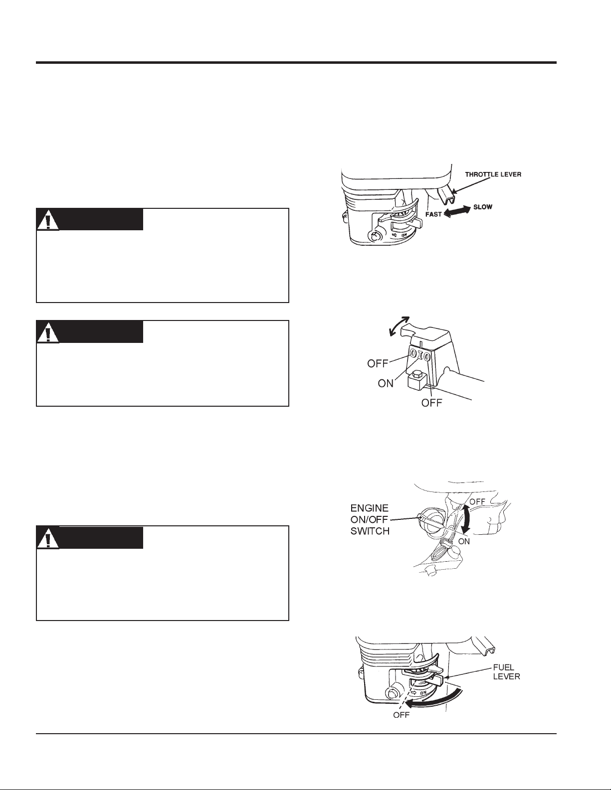
2. Place the
fuel valve lever
(Figure 19) to the "ON" position.
Figure 19. Engine Fuel Valve Lever
PAGE 24 — FCG16HA SAW • OPERATION AND PARTS MANUAL — REV. #1 (03/19/10)
Page 25
3.
Place the engine Shutdown switch (next to the handle
lock), and the engine ON/OFF switch on the engine to the
"ON" position. Shutting the engine off using this switch
confirms that is is functioning properly.
Always use the Engine Shutdown Safety Switch
located next to the handle lock to shut down the
engine. Shutting the engine off using this switch
confirms that is is functioning properly.
OPERATION
4. Place the
position.
Choke Lever
CAUTIONCAUTION
CAUTION
CAUTIONCAUTION
(Figure 20) in the "
Figure 20. Choke Lever
CLOSED
"
Figure 21. Throttle Lever
6. Grasp the starter grip (Figure 22) and slowly pull it out. The
resistance becomes the hardest at a certain position, corresponding to the compression point. Pull the starter grip briskly
and smoothly for starting.
CAUTIONCAUTION
CAUTION
CAUTIONCAUTION
DO NOT pull the starter rope all the way to the end. DO
NOT release the starter rope after pulling. Allow it to
rewind as soon as possible.
The engine speed has been set at the
factory. Changing the governor speed could
damage the blade and/or the saw.
Rotate the
5.
and
engine governor speed is factory set to ensure optimum
blade operating speeds.
throttle lever
slow
for starting. All sawing is done at
FCG16HA SAW • OPERATION AND PARTS MANUAL — REV. #1 (03/19/10) — PAGE 25
(Figure 21) halfway between
full throttle
fast
. The
Figure 22. Starter Grip
Page 26
OPERATION
7. If the engine has started, slowly return the choke lever
(Figure 20) to the
started repeat steps 1 through 5.
8. Before the saw is placed into operation, run the engine for
several minutes. Check for fuel leaks, and noises that would
associate with a loose guards and/or covers.
9. Rotate the throttle lever (Figure 21) toward full throttle.
WARNINGWARNING
WARNING
WARNINGWARNING
ALWAYS cut with the saw at FULL THROTTLE. Attempting
to cut with the saw at less than full throttle could cause the
blade to bind or stop abruptly in the slab resulting in serious
injury to the operator or others in the area.
WARNINGWARNING
WARNING
WARNINGWARNING
ALWAYS keep clear of
operating this equipment.
"OPEN"
position. If the engine has not
rotating
or
moving
parts while
Stopping the Engine
Stopping the engine under normal conditions:
1. Place the
position, and listen for the engine speed to decrease. Allow
engine to run for 2 or 3 minutes for proper cooldown.
2.
Turn the engine Shutdown switch (next to the handle lock)
(Figure 24) to the "OFF" position. Shutting the engine off
using this switch confirms that is is functioning properly.
engine throttle lever
Figure 23. Throttle Lever
(Figure 23) in the SLOW
To begin sawing, lower the rotating blade allowing it to cut to
10.
the preset depth.
11. When blade has reached full cutting depth, slowly walk
behind the saw at a rate that will allow the engine to operate
without losing optimum RPM.
CAUTIONCAUTION
CAUTION
CAUTIONCAUTION
DO NOT try to cut faster than the blade will allow. Cutting
too fast will cause the blade to rise up out of the cut.
Improper cutting rate can decrease the life of the engine
and blades.
12. When the end of the cut has been reached, raise the blade
out of the cut by pulling back on the handlebars (using a
downward pressure) until the raise/lower rod drops into its
slot with the blade in the raised position.
13. If cutting is complete, shut the saw down using the following
"Shutdown Procedures".
3. Turn the
position.
4. Place the fuel valve lever (Figure 26) to the OFF position.
Figure 24. Engine Shutdown Switch
engine ON/OFF switch
Figure 25. Engine ON/Off Switch ( engine)
Figure 26. Fuel Valve Lever (Off Position)
(Figure 25) to the "OFF"
PAGE 26 — FCG16HA SAW • OPERATION AND PARTS MANUAL — REV. #1 (03/19/10)
Page 27

Restarting After Intervention
If cutting is interrupted where the engine stops or is turned off
while the blade is still in the cut:
a. Turn engine Shutdown switch (next to the handle lock)
to the "OFF" position.
b. Raise the blade out of the cut
c. Restart the engine as described in the Start-Up sections
on page 24.
CAUTIONCAUTION
CAUTION
CAUTIONCAUTION
The only acceptable method for freeing a stuck blade is to
remove the saw from the stuck or pinched blade. DO
NOT try to get the blade unstuck using the Raise/Lower
system or by lifting the saw by the lifting bale, etc.
If cutting is interrupted where the blade is stuck in the cut:
OPERATION
a. Turn engine Shutdown switch (next to the handle lock)
to the "OFF" position.
b. Remove the blade guard.
c. Remove blade mounting bolt and outer flange.
d. Maneuver the saw away from the stuck blade.
e. A parallel cut made next to the blade may be necessary
to free it.
f. Once the blade is freed inspect the blade for damage;
discard if damaged.
e Ensure an undamaged, useable blade is installed on
the saw before cutting is resumed with that saw.
FCG16HA SAW • OPERATION AND PARTS MANUAL — REV. #1 (03/19/10) — PAGE 27
Page 28

3. Adjust the front pointer so it just touches the side of the
See the engine manual supplied with your
straight-edge or level.
machine for appropriate
engine maintenance schedule and
4. Remove the straight-edge or level.
troubleshooting guide for problems.
5. Position the front pointer and blade directly over the chalk
line.
MAINTENANCE
CAUTIONCAUTION
CAUTION
CAUTIONCAUTION
ALWAYS allow the engine to cool before
servicing. NEVER attempt any maintenance
hot!
ANY
engine part
engine.
or
INSTALLING
front or rear pointers
any components
engine mounting bolts
drive belt, arbor shaft, arbor shaft bearings
blades
work on a
WARNINGWARNING
WARNING
WARNINGWARNING
ALWAYS ensure that the engine
ON/OFF switch is in the "OFF"
position and that the arbor shaft has
COMPLETELY STOPPED
ROTATING before performing any
of the the following operations:
■
REMOVING
■
ADJUSTING
■
LUBRICATING
■
REMOVING
■
INSPECTING, ADJUSTING, OR
REPLACING
or
6. Start the saw and lower the blade onto the chalk line.
7. Begin cutting and make sure the blade follows the chalk line
as closely as possible.
8. The pointer should follow the chalk line as well. If it does not,
adjust the pointer by loosening then tightening the jam nuts
on the pointer until the pointer follows the same path as the
blade.
Rear Guide Adjustment
The rear guide is useful on long runs that allow the operator to
follow the line with less effort as well as cutting up to a wall
where the front pointer is lifted.
1. Chalk out a straight line on the prepared slab or cutting
surface.
2. Cut a straight line about 10 - 12 feet (3 - 4 meters) in length.
3. Adjust the rear guide until it falls into the cut.
4. The rear guide should ride in the cut freely without the feel
of it pushing the front pointer or blade off line. If it feels like it
is doing so, turn the saw off and after the blade has COMPLETELY STOPPED ROTATING, adjust the rear guide by
loosening then tightening the jam nuts on the guide until it
rides freely in the cut.
Saw Blade Removal and Installation
Saw blade removal and installation is covered on pages 21.
Front Pointer Adjustment
The front pointer and rear guide have been set at the factory.
Use these procedures only if the pointer or guide are suspect of
being out of alignment.
1. Chalk out a straight line on the prepared slab or cutting
surface.
2. Use a 4 foot straight-edge or level by placing it flat against
the blade.
General Engine Care
Engine check:
Check daily for any oil and/or fuel leakage, thread nut & bolt
tightness, and overall cleanliness.
Engine oil:
Check daily. Inspect with blade removed and saw frame
level on a level surface. Keep the oil clean, and at the proper
servicing level (Figure 8). DO NOT OVERFILL! SAE 10W-
30 of SG is recommended for general use.
Engine oil change:
Change engine oil after the first month or 20 hours of
operation, then every 3 months/or 50 HOURS of operation.
See Engine Owner’s Manual for detailed information.
PAGE 28 — FCG16HA SAW • OPERATION AND PARTS MANUAL — REV. #1 (03/19/10)
Page 29

MAINTENANCE
Engine tank & strainer:
Clean every year/or 300 hours.
Fuel line:
Replace every two years/or as necessary.
Spark plug:
Clean/adjust every 6 months/or 100 hours. Replace every
year/ or 300 hours.
Chassis Lubrication
Regular lubrication of various components of the FCG16HA Saw
are critical to ensure a reasonable service life. Lubricate the
following components:
Drive Belt
Refer to pages 17 to 18 of this manual for Drive Belt adjustment
procedures and Removal and Replacement procedures.
Blade Shaft Bearings
Two zerk fittings are located at the lower-front area of the saw.
Lubricate before daily use. Use a good quality automotive or
general purpose grease. Check and lubricate more often if unit
is under heavy use. Do not overfill bearings. Overfilling can
damage the grease seals which can result in bearing exposure
to dirt and contaminants which can then shorten the life of the
bearings. Excess grease can also drip onto the cutting surface.
Engine Oil Change
Drain the used oil while the engine is warm by the following:
Refer to Figure 27.
1. Place an oil pan or suitable container below the engine drain
plug to catch the used oil.
2. Remove the filler cap/dipstick and the drain plug.
3. Drain the oil completely and reinstall the drain plug. Ensure
the drain plug is tightened securely.
4. Make sure the engine is in a level position and fill to the outer
edge of the oil filler hole with the recommended oil. (See
Table 5.) Engine oil capacity is 0.63 US quart (0.60 liter).
Running the engine with a low oil level can cause engine
damage.
Dispose of used oil properly. DO NOT pour used
oil on the ground, down a drain, or throw in the
trash. Used oil can generally be taken to your
local recycling center or service station for
reclamation.
CAUTIONCAUTION
CAUTION
CAUTIONCAUTION
5. Screw in the filler cap/dipstick securely.
Figure 27. Engine Oil Change
FCG16HA SAW • OPERATION AND PARTS MANUAL — REV. #1 (03/19/10) — PAGE 29
Page 30

TROUBLESHOOTING (SAW)
GNITOOHSELBUORTEDALB.6ELBAT
MOTPMYS MELBORPELBISSOP NOITULOS
gnieblairetamehtrofdrahootedalB
?tuc
foesuacebdehsinimideuqrotenignE
?tleb-Vesool
,gnittucspotsroswolsedalB
edalbnosniamerllits
thgiartstuctonseodedalB
.eurtro/dna
?gnittuc
?rewopenignEtneiciffusnI .rewopesrohenignEkcehC.gnitteselttorhtkcehC
?tucgnieblairetam
?segnalfdnasredluohs
?noitatorfonoitcecridreporpmI
?tfahsedalbehtnognippilssiedalB
?wasdengilasimnodesugniebedalB .ytirgetnitnemngiladnasgniraebtfahsedalbkcehC
ehtrofdrahylevissecxesiedalB
?MPRreporpmitadesugniebedalB
robranodetnuomylreporpmiedalB
elihwedalbotdeilppaecrofevissecxE
TONOD dnawolsaylppA.tucehtniedalbehtecrof
.edalbeht"sserdeR"
.tleB-Vecalperro/dnanethgiT
.noitcerid"gnittuC-nwoD"anistniopworra
.tfahsedalbeht
.noitamrofnirofpiuqitluMrorelaeDtlusnoC.tuc
.000,6yletamixorppa
.gniwasnehwecapydaets
gnittucyrT.edalbtcerrocrofpiuqitluMrorelaeDtlusnoC
ot)kcolbrednic,kcirbacilis,enotsdnas(lairetamtfosyrev
lanoitatordnadetneiroylreporpsiedalbehttahtkcehC
nodellatsniylreporperanipegnalf&edalbehttahtkcehC
gnieblairetamehthtiwedalbehtfonoitacificepskcehC
si)MPFS(deepsetunimrepteefecafrusedalberusnE
.tfahsedalbehtnodexiffaylreporpsiedalberusnE
gnieblairetamehtrofdrahootsedalB
?tuc
robranodetnuomylreporpmiedalB
??segnalfdnasredluohs
gnilkcarc,gnirolocsidedalB
.ylevissecxegniraewro/dna
?dnuorfotuoelohrobrA .tfahsedalbehtnodexiffaylreporpsiedalberusnE
?tucgnieb
?gnittuc
?riagniloochguonegniviecertonedalB
lairetamrofnesohcedalbtcerrocnI
elihwedalbotdeilppaecrofevissecxE
TONOD dnawolsaylppA.tucehtniedalbehtecrof
.edalbeht"sserdeR"
.ed
albgnittucyrdatuoba
.gniwasnehwecapydaets
PAGE 30 — FCG16HA SAW • OPERATION AND PARTS MANUAL — REV. #1 (03/19/10)
gnittucyrT.edalbtcerrocrofpiuqitluMrorelaeDtlusnoC
ot)kcolbrednic,kcirbacilis,enotsdnas(lairetamtfosyrev
.tfahsedalbehtnodexiffaylreporpsiedalberusnE
tewrofdedivorpsiretawfoemulov&wolfreporperusnE
detalucricsiriagnilooctneiciffuserusnE.sedalbgnittuc
gnieblairetamehthtiwedalbehtfonoitacificepskcehC
.noitamrofnirofpiuqitluMrorelaeDtlusnoC.tuc
Page 31

TROUBLESHOOTING (ENGINE)
)ENIGNE(GNITOOHSELBUORT.7ELBAT
MOTPMYSESUACELBISSOPNOITULOS
?gnigdirbgulpkrapS
?gulpkrapsnotisopednobraC .gulpkrapsecalperronaelC
tub,elbaliavasileuf",tratsottluciffiD
."gulpkrapstaKRAPSon
?noitalusni
dna,elbaliavasileuf",tratsottluciffiD
."gulpkrapsehttatneserpsiKRAPS
,elbaliavasileuf",tratsottluciffiD
atneserpsikraps
."lamron
sinoisserpmocdn
droretaW.metsysleufhsulF
?nepOekohC.ekohCesolC
ifedoteudtiucrictrohS
?paggulpkrapsreporpmI.pagreporp
?detrohssihctiwsFFO/NO .hctiws
?evitcefedliocnoitingI.liocnoitingiecalpeR
onekorberiwgulpkrapS .gniriwgulpkrapsevitcefedecalpeR
?epytleufgnorW .leuffoepyttcerrochtiwecalperdna,metsysleufhsulF
?metsysleufnitsu
?ytridrenaelcriA .renaelcriaecalperronaelC
gulpkrapstneic
?ytridstniop,pagkrapsreporpmI .stnio
?gnitiucrictrohsronrownoitalusniresnednoC.resnednocecalpeR
?gnitiucrictrohsr
?dedurtorprokcutsevlavtsuahxe/noitcuS.sevlavtaes-e
otteS
ecalper,gniriwhctiwskcehC
pnaelcdnapagkrapstcerrocteS
R
.gulpkrapsecalperronoitalusni,pagkcehC
.nrowfiecalper,noitalusnigulpkrapskcehC
,tratsottluciffiD
."wol
,elbaliavasileuf"
sinoisserpmocdnatneserpsikraps
lreporp
?y
?degamad
?deggol
cretlifleuF.retlifleufecalpeR
.roterubracehttatneserpleufoN
?enilleufniriA.en
?nrowrednilycro/dnagnirnotsiP .notsiprodnasgnirnotsipecalpeR
denethgittongulpkrapsro/dnadaehrednilyC
teksaggulpkrapsro/dnateksagdaeH
?knatleufnielbaliavatonleuF .leuffoepyttcerrochtiwlliF
?deggolcelohrehtaerbpacknatleuF .packnatleufecalperronaelC
.gulpkrapsdnastlobdaehrednilyceuqroT
adaehecalpeR
illeufdeelB
.steksaggulpkrapsdn
FCG16HA SAW • OPERATION AND PARTS MANUAL — REV. #1 (03/19/10) — PAGE 31
Page 32

TROUBLESHOOTING (ENGINE)
)DEUNITNOC,ENIGNE(GNITOOHSELBUORT.7ELBAT
MOTPMYSESUACELBISSOPNOITULOS
?naelctonrenaelcriA .renae
reporpsinoisserpmoc"rewopnikaeW"
.erifsimtonseoddna
eD .gulpkrapsecalperronaelC
reporpsinoisserpmoc"rewopnikaeW"
mtub
.serifsi
?gulpkrapsytriD .gulpkrapsecalperronaelC
?epytleufgnorW
.staehrevoenignE
?ytridsnifgnilooC.
?roterubracnilevelreporpmI
?gulpkrapsevitcef
?paggulpkrapsreporpmI.pagreporpotteS
?metsysleufniretaW
?evitcefedliocnoitingI.liocnoitingi
?reporpmieulavtaehgulpkrapS .gulpkrapsfoepyttcerrochtiwecalpeR
?yltcerrocdetsujdaronrevoG.ronrevogtsujdA
.leufepyt
ecalpeR
sysleufhsulF
.leuffoepyt
lcriaecalperronaelC
.tnemtsujdataolfkcehC
.roterubracdliubeR
tcerrochtiwecalperdnametsysleufhsulF
tcerrochtiwecalperdna,met
snifgniloocnaelC
.setautculfdeepslanoitatoR
lamretratslioceR
.noitcnuf
gnirpsronrevoG .gnirpsronrevogecalpeR
?detcirtserwolfleuF .sgolcroskaelrofmetsysleuferitnekcehC
?esoolgnirpslaripS.gnirpslaripsecalpeR
?gnissimroevitcefed
?triddnatsudhtiwdeggolcmsinahcemlioceR .retawdnapaoshtiwylbmessaliocernaelC
PAGE 32 — FCG16HA SAW • OPERATION AND PARTS MANUAL — REV. #1 (03/19/10)
Page 33

NOTES
FCG16HA SAW • OPERATION AND PARTS MANUAL — REV. #1 (03/19/10) — PAGE 33
Page 34

EXPLANATION OF CODE IN REMARKS COLUMN
The following section explains the different symbols and
remarks used in the Parts section of this manual. Use the
help numbers found on the back page of the manual if there
are any questions.
NOTICE
The contents and part numbers listed in the parts
section are subject to change without notice. Multiquip
does not guarantee the availability of the parts listed.
SAMPLE PARTS LIST
NO. PART NO. PART NAME QTY. REMARKS
1 12345 BOLT ......................1 .....INCLUDES ITEMS W/%
2% WASHER, 1/4 IN. ...........NOT SOLD SEPARATELY
2% 12347 WASHER, 3/8 IN. ...1 .....MQ-45T ONLY
3 12348 HOSE ..................A/R ...MAKE LOCALLY
4 12349 BEARING ..............1 .....S/N 2345B AND ABOVE
NO. Column
Unique Symbols — All items with same unique
symbol
QTY. Column
Numbers Used — Item quantity can be indicated by a
number, a blank entry, or A/R.
A/R (As Required) is generally used for hoses or other
parts that are sold in bulk and cut to length.
A blank entry generally indicates that the item is not sold
separately. Other entries will be clarified in the “Remarks”
Column.
REMARKS Column
Some of the most common notes found in the “Remarks”
Column are listed below. Other additional notes needed
to describe the item can also be shown.
Assembly/Kit — All items on the parts list with the
same unique symbol will be included when this item is
purchased.
Indicated by:
“INCLUDES ITEMS W/(unique symbol)”
(@, #, +, %, or >) in the number column belong to the
same assembly or kit, which is indicated by a note in the
“Remarks” column.
Duplicate Item Numbers — Duplicate numbers indicate
multiple part numbers, which are in effect for the same
general item, such as different size saw blade guards in
use or a part that has been updated on newer versions
of the same machine.
NOTICE
When ordering a part that has more than one item
number listed, check the remarks column for help in
determining the proper part to order.
PART NO. Column
Numbers Used — Part numbers can be indicated by a
number, a blank entry, or TBD.
TBD (To Be Determined) is generally used to show a
part that has not been assigned a formal part number
at the time of publication.
A blank entry generally indicates that the item is not sold
separately or is not sold by Multiquip. Other entries will
be clarified in the “Remarks” Column.
Serial Number Break — Used to list an effective serial
number range where a particular part is used.
Indicated by:
“S/N XXXXX AND BELOW”
“S/N XXXX AND ABOVE”
“S/N XXXX TO S/N XXX”
Specific Model Number Use — Indicates that the part
is used only with the specific model number or model
number variant listed. It can also be used to show a
part is NOT used on a specific model or model number
variant.
Indicated by:
“XXXXX ONLY”
“NOT USED ON XXXX”
“Make/Obtain Locally” — Indicates that the part can
be purchased at any hardware shop or made out of
available items. Examples include battery cables, shims,
and certain washers and nuts.
“Not Sold Separately” — Indicates that an item cannot
be purchased as a separate item and is either part of an
assembly/kit that can be purchased, or is not available
for sale through Multiquip.
PAGE 34 — FCG16HA SAW • OPERATION AND PARTS MANUAL — REV. #1 (03/19/10)
Page 35

FCG16HA CONCRETE SAW 1 TO 3 UNITS
WITH HONDA GX200QXC9 ENGINE
1 to 3 Units
Qty. ........ P/N .............................. Description
2 ............ 16052 .......................... BELT
4 ............ 25407 .......................... WHEELS
2 ............ 15028 .......................... COLLARS, WHEEL
2 ............ 15081 .......................... GRIP, HANDLE
1 ............ 25380 .......................... BLADE, SHAFT/FLANGE
2 ............ 15359 .......................... BEARING, PILLOW BLOCK
1 ............ 19710 .......................... NUT, BLADE
3 ............ 17210ZE1505 ............. AIR FILTER
3 ............ 9807956846 ................ SPARK PLUG
1 ............ 17620ZH7023 ............. FUEL CAP, TANK
1 ............ 28462ZH8003 ............. STARTER ROPE
SUGGESTED SPARE PARTS
FCG16HA SAW • OPERATION AND PARTS MANUAL — REV. #1 (03/19/10) — PAGE 35
Page 36

DECAL LOCATOR
DECAL LOCATOR
16
DEPTH
CONTROL
(mm)
(102)
(76)
(51)
(25)
17
3
2
D
W
E
R
O
1
A
“BELT DRIVE”
WARNING
California - Proposition 65 Warning
Engine exhaust and some of its byproducts
are known to the State of California to cause
cancer,birth defects, and other reproductive
harm.
8
9
WARNING
Always use approved
respiratory protection.Adhere
to safety guidelines. OSHA
Regulations (Standards29 CFR) 1926.136 &1910/103
“HOT”
In
4
7
3
2
1
C
10
WARNING
Never operate the saw without
the guards in place.Adhere to
safety guidelines:ANSI Code
29 CFR) 1910.215.
5
4
MODEL
SERIAL NO.
A
P
C
O
D
E
A
T
BELT DRIVE
GEAR DRIVE
CLOCKWISE
GEAR DRIVE
6
11
B
CHECK
CHECK
C
COUNTER
HOT
CLOCKWISE
LIFTING POINTLIFTING POINT
O
T
R
A
T
I
O
N
2
D
D
LUBRICATION
LUBRICATION
“LUBRICATION”
B
“CHECK”
12
A
T
T
I
O
O
R
P/N 25491
LUBRICATION
N
13
LUBRICATION
PAGE 36 — FCG16HA SAW • OPERATION AND PARTS MANUAL — REV. #1 (03/19/10)
Page 37

DECAL LOCATOR
DECAL LOCATOR
NO. PART NO. PART NAME QTY. REMARKS
1 38231 DECAL, SLAB SAVER LARGE 1
2 38213 DECAL, MQ LOGO 3.0 X 3-3/4 2
3 36099 DECAL, SAFETY CLOTHING ISO BLUE ............................. 1 .......... SAFETY ITEM
4 13118 DECAL, POWDER COATED 1
5 SERIAL NUMBER PLATE ...................................................... 1 .......... CONTACT PARTS DEPT.
6 38230 DECAL, SLAB SAVER SMALL 1
7 25427 DECAL, DEPTH INDICATOR 1
8 20525 DECAL, CA PROP 65 ............................................................ 1 .......... SAFETY ITEM
9 15580 DECAL, WARN RESPIRATORY 1-1/2 X 3 .............................. 1 .......... SAFETY ITEM
10 15581 DECAL, WARN BLADE GUARD 1-1/2 X 3 ............................. 1 .......... SAFETY ITEM
11 38239 DECAL, MQ LOGO 1
12 25491 DECAL, BLADE ROTATION CW ............................................. 1 .......... SAFETY ITEM
13 11246 DECAL, INTL STDS ISO BLACK ........................................... 1 .......... SAFETY ITEM
14 25867 DECAL, ROTATION IN DISPLACEMENT ............................... 1 .......... SAFETY ITEM
15 35137 DECAL, READ MANUAL ........................................................ 1 .......... SAFETY ITEM
16 38226 DECAL, CE BLACK 1
17 35166 DECAL, DECAL, GUARANTEED SOUND POWER 112 db 1
FCG16HA SAW • OPERATION AND PARTS MANUAL — REV. #1 (03/19/10) — PAGE 37
Page 38

GUARDS ASSY.
GUARDS ASSY.
1
2
5
7
6
12
5
10
11
4
2
3
4
3
17
12
8
14
15
16
16
12
PAGE 38 — FCG16HA SAW • OPERATION AND PARTS MANUAL — REV. #1 (03/19/10)
13
14
16
15
9
Page 39

GUARDS ASSY
GUARDS ASSY.
NO. PART NO. PART NAME QTY. REMARKS
1 25387 GUARD, BELT ...................................................... 1 ......... SAFETY ITEM
2 4196 SCREW, HHC 3/8 - 16 X 0.75 3
3 0166 A WASHER, LOCK 3/8 MED 3
4 10136 WASHER, FLAT 3/8 SAE 3
5 12287 SCREW, THP 1/4 - 20 X 3/4 SS 3
6 25430 SHEET, REAR WATER SHIELD ........................... 1 ......... SAFETY ITEM
7 25431 FLAP, REAR WATER SHIELD.............................. 1 ......... SAFETY ITEM
8 15161 STOP, RUBBER BUMPER 1
9 25397 GUARD, BLADE 10" DOOR ................................. 1 ......... SAFETY ITEM
10 25428 SHEET, FLAP MOUNT ........................................ 1 ......... SAFETY ITEM
11 25429 FLAP, FRONT WATER SHIELD ........................... 1 ......... SAFETY ITEM
12 10024 NUT, NYLOC 1/4 - 20 7
13 15509 SPRING, CENTURY ............................................ 1 ......... SAFETY ITEM
14 0424 SCREW, HHC 1/4 - 20 X 1-1/4 2
15 0949 NUT, HEX FINISH 1/4 - 20 4
16 0948 WASHER, FLAT 1/4 SA3 8
17 25401 PIN, HINGE 0.5 X 2.5 1
FCG16HA SAW • OPERATION AND PARTS MANUAL — REV. #1 (03/19/10) — PAGE 39
Page 40

GUIDES ASSY.
GUIDES ASSY.
PAGE 40 — FCG16HA SAW • OPERATION AND PARTS MANUAL — REV. #1 (03/19/10)
Page 41

GUIDES ASSY.
GUIDES ASSY.
NO. PART NO. PART NAME QTY. REMARKS
1# 20473 SCREW, HHC 3/8 - 16 X 3 FULL THRD 1
2# 1456 NUT, HEX FINISH 3/8 - 16 4
3# 1007 NUT, HEX JAM 3/8 - 16 4
4# 25449 WHEEL, GUIDE 3.5 OD X .41 ID FCG 1
5# 10133 NUT, NYLOC 3/8 - 16 1
6 25392 SHEET, REAR GUIDE ...................................................... 1 ......... NO LONGER AVAILABLE
7# 3215 SCREW, HHC 1/2 - 13 X 3-1/2 1
8# 36128 WASHER, NYLON 1/2" ID 4
9# 10176 NUT, NYLOC 1/2 - 13 1
10
11
12
13
14
15
16
17
18
19
20 35097 POINTER (GUIDE) ASSY., WHEEL STYLE .................... 1 ......... INCLUDES ITEMS W/
21 25416 GUIDE, REAR ASSY. ....................................................... 1 ......... NO LONGER AVAILABLE
21 38362 GUIDE, REAR ASSY. ....................................................... 1 ......... FEB, 2010
22
23
24# 38365 MAGNET, FCG REAR ARM 1
25# 19847 RIVET, POP, ALUM, 3/16X1/8-1/4 GRIP 2
26# 38366 ARM, REAR POINTER WHEEL 1
27 10133 NUT, NYLOC 3/8 - 16 2
35476 SCREW, SHC 5/16-18 X 3.5 FULL THRD 1
*
21369 BEARING, SEALED 5/16 ID X 7/8 OD 2
*
21189 WHEEL, 2.13 OD X 1.25 W POLYURETHANE 1
*
21185 SPACER, 1/2 X 5/16 X 3/8 P33-3 1
*
21368 PLATE, POINTER (GUIDE) FCG 1
*
5283 NUT, NYLOC 5/16-18 2
*
0161 D NUT, HEX FINISH 5/16-18 2
*
35096 SASH ASSY., WIRE ROPE 1
*
19470 WASHER, FLAT 5/16 USS 1
*
35093 ARM, FRONT POINTER (GUIDE) W/A, FCG 1
*
....................................................................................................... INCLUDES ITEMS W/#
0205 SCREW, HHC 3/8 - 16 X 1.0 2
*
0202 SCREW, HHC 5/16 - 18 X 1 ZINC 1
*
*
FCG16HA SAW • OPERATION AND PARTS MANUAL — REV. #1 (03/19/10) — PAGE 41
Page 42

UNDER CARRIAGE ASSY.
UNDERCARRIAGE ASSY.
14
1
13
2
12
UNDERCARRIAGE ASSEMBLY
3
4
10
2
7
6
5
3
8
9
11
3
2
PAGE 42 — FCG16HA SAW • OPERATION AND PARTS MANUAL — REV. #1 (03/19/10)
Page 43

UNDERCARRIAGE ASSY.
UNDER CARRIAGE ASSY.
NO. PART NO. PART NAME QTY. REMARKS
1 25368 BAR, PIVOT SHAFT 1
2 25407 WHEEL, 5 X .625 X 1.5 BALL BRG 4
3 15028 COLLAR, SET 5/8 DIA 4
4 25379 BEARING, 5/8 FLANGE UHMW 2
5 9154 SCREW, HHC 3/8 - 16 X 1-3/4 1
6 2064 ROD END, 3/8 -24 FEM RH 1
7 2199 NUT, HEX JAM 3/8 -24 1
8 10136 WASHER, FLAT 3/8 SAE AR
9 10133 NUT, JAM 3/8 - 16 1
10 29448 SCREW, THP 1/4 - 20 X X 1.25 4
11 25365 RAISE-LOWER W/A 1
12 15414 UNDERCARRIAGE ASSEMBLY 1
13 25489 PLUG, 3/4 BLK PLASTIC 2
14 25409 CAP, 1-1/2 ID BLACK 1
FCG16HA SAW • OPERATION AND PARTS MANUAL — REV. #1 (03/19/10) — PAGE 43
Page 44

HANDLE & DEPTH ADJUSTER ASSY.
HANDLE & DEPTH ADJUSTER ASSY.
14
13
2
1
10
11
15
5
3
7
8
9
4
6
12
PAGE 44 — FCG16HA SAW • OPERATION AND PARTS MANUAL — REV. #1 (03/19/10)
Page 45

HANDLE & DEPTH ADJUSTER ASSY.
HANDLE & DEPTH ADJUSTER ASSY.
NO. PART NO. PART NAME QTY. REMARKS
1 25357 FRAME 1
2 25419 HANDLEBAR 1
3 15503 KNOB, COMFORT GRIP 1
4 4403 KNOB, SHIFT 1
5 25448 DEPTH ADJUST DISK 1
6 25480 SCREW PLUNGER, 1/4 - 20 X 17/32 1
7 25446 ROD, DEPTH STOP 1
8 2199 NUT, HEX JAM 3/8 -24 1
9 2064 ROD END, 3/8 -24 FEM RH 1
10 9154 SCREW, HHC 3/8 - 16 X 1-3/4 1
11 10136 WASHER, FLAT 3/8 SAE AR
12 10133 NUT, NYLOC 3/8 - 16 1
13 1007 NUT, HEX JAM 3/8 - 16 1
14 9154 SCREW, HHC 3/8 - 16 X 3 1
15 15081 GRIP, HANDLE 2
FCG16HA SAW • OPERATION AND PARTS MANUAL — REV. #1 (03/19/10) — PAGE 45
Page 46

ENGINE & BLADE DRIVE ASSY.
ENGINE & BLADE DRIVE ASSY.
3
2
4
1
6
5
22
1
3
23
2
4
7
8
9
10
11
12
18
13
18
14
15
20
19
17
16
21
NOTES:
SWITCH MOUNTING HARDWARE
1
IS INCLUDED WITH SWITCH.
PAGE 46 — FCG16HA SAW • OPERATION AND PARTS MANUAL — REV. #1 (03/19/10)
Page 47

ENGINE & BLADE DRIVE ASSY.
ENGINE & BLADE DRIVE ASSY.
NO. PART NO. PART NAME QTY. REMARKS
1 25378 ENGINE, 6.5 HP HONDA GX200UQXC9 (SHOWN) 1
2 0161 D NUT, HEX FINISH 5/16 - 18 4
3 0161 C WASHER, LOCK 5/16 MED 4
4 0300 B WASHER, FLAT 5/16 4
5 25356 PULLEY, 13V412SH 1
6 25417 BUSHING, PULLEY SH - 3/4 1
7 16052 BELT, 3VX335 GATES/OPTIPLEX 1
8 0169 SCREW, HHC 3/8 - 16 X 3.0 4
9 0166 A WASHER, LOCK 3/8 MED 4
10 25377 SPACER, BEARING 2
11 15359 BEARING, PIL BLOCK, BRN. VTBS-212 2
12 1162 A CAP, GREASE ZERK #2 2
13 25442 PULLEY, 1F3V26 3/4" BORE 1
14 0627 KEY, SQ 3/16 X 1-1/4 1
15 25380 BLADE, SHAFT/FLANGE ASM 1
16 25418 FLANGE, 3.38 O.D. 1
17 19710 NUT, HEX 5/8 - 11 LH THRD 1
18 25410 BOLT, CARRAIGE 5/16 - 18 X 1.75 3
19 25487 WRENCH, SERVICE 15/16 OPEN END 1
20 25488 WRENCH, 5/8 COMBO 1
21 9SWG BLADE, DIAMOND BACK ......................................... 1 ......... ORDER FROM UNIT SALES DEPT.
22 35127 SWITCH, ENGINE SHUT-OFF MAGURA ................. 1 ......... SAFETY ITEM
23 35155 WIRE ASSY., ENGINE SHUT-OFF SWITCH ............ 1 ......... SAFETY ITEM
FCG16HA SAW • OPERATION AND PARTS MANUAL — REV. #1 (03/19/10) — PAGE 47
Page 48

HONDA GX200QXC9 — AIR CLEANER (CYCLONE) ASSY.
AIR CLEANER (CYCLONE) ASSY.
PAGE 48 — FCG16HA SAW • OPERATION AND PARTS MANUAL — REV. #1 (03/19/10)
Page 49

HONDA GX200QXC9 — AIR CLEANER (CYCLONE) ASSY.
AIR CLEANER (CYCLONE) ASSY.
NO. PART NO. PART NAME QTY. REMARKS
1 16271ZE1000 GASKET, ELBOW 1
2 17210ZE1505 ELEMENT, AIR CLEANER (DUAL) .........................1 ............. INCLUDES ITEMS W/
3
4
5 17230ZE1841 COVER, AIR CLEANER (DUAL) 1
6
7+ 17238ZE7010 COLLAR, AIR CLEANER 2
8+ 17239733000 COLLAR B, AIR CLEANER 1
9 17410ZE1840 ELBOW, AIR CLEANER ......................................... 1 ............. INCLUDES ITEMS W/+
10 17470ZE1841 CASE, PRE AIR CLEANER 1
11 17475ZE1841 CAP, PREAIR CLEANER 1
12 17476ZE1841 GUIDE, PRE AIR CLEANER 1
13 17478ZE1841 PLATE, PRE AIR CLEANER 1
14 90300GB0900 BOLT, MUDGUARD 5
15 90325044000 WINGNUT, TOOL BOX SETTING 2
16 9405006000 NUT, FLANGE 6MM 2
17 957010602000 BOLT, FLANGE 6 X 20 1
17218ZE1821 FILTER (OUTER) 1
*
17219733010 GASKET, AIR CLEANER COVER 1
*
17232891000 GROMMET, AIR CLEANER 1
*
*
FCG16HA SAW • OPERATION AND PARTS MANUAL — REV. #1 (03/19/10) — PAGE 49
Page 50

CAMSHAFT ASSY.
HONDA GX200QXC9 — CAMSHAFT ASSY.
PAGE 50 — FCG16HA SAW • OPERATION AND PARTS MANUAL — REV. #1 (03/19/10)
Page 51

HONDA GX200QXC9 — CAMSHAFT ASSY.
CAMSHAFT ASSY.
NO. PART NO. PART NAME QTY. REMARKS
1 12209ZH8003 SEAL, VALVE STEM 1
2 14100ZL0000 CAMSHAFT ASSEMBLY ........................................ 1 ............. INCLUDES ITEM W/
3 14410ZE1010 ROD, PUSH 2
4 14431ZE1000 ARM, VALVE ROCKER 2
5 14451ZE1013 PIVOT, ROCKER ARM 2
6
7 14711ZF1000 VALVE, INTAKE 1
8 14721ZF1000 VALVE, EXHAUST 1
9 14731ZL0000 LIFTER, VALVE 2
10 14751ZF1000 SPRING, VALVE 2
11 14771ZE1000 RETAINER, INTAKE VALVE SPRING 1
12 14773ZE1000 RETAINER, EXHAUST VALVE SPRING 1
13 14781ZE1000 ROTATOR, VALVE 1
14 14791ZE1010 PLATE, PUSH ROD GUIDE 1
15 90012ZE0010 BOLT, PIVOT 8MM 2
16 90206ZE1000 NUT, PIVOT ADJ. 2
14568ZE1000 SPRING, WEIGHT RETURN 1
*
*
FCG16HA SAW • OPERATION AND PARTS MANUAL — REV. #1 (03/19/10) — PAGE 51
Page 52

CARBURETOR ASSY.
HONDA GX200QXC9 — CARBURETOR ASSY.
PAGE 52 — FCG16HA SAW • OPERATION AND PARTS MANUAL — REV. #1 (03/19/10)
Page 53

HONDA GX200QXC9 — CARBURETOR ASSY.
CARBURETOR ASSY.
NO. PART NO. PART NAME QTY. REMARKS
1
2
3
4
5
6
7
8
9 16100ZL0V21 CARBURETOR ASSEMBLY (BE64F B) ................. 1 ............. INCLUDES ITEMS W/
10
11
12
13 16211ZL0000 INSULATOR, CARBURETOR 1
14 16212ZH8800 GASKET, INSULATOR 1
15 16220ZE1020 SPACER, CARBURETOR 1
16 16221ZH8801 GASKET, CARBURETOR 1
17 16610ZE1000 LEVER, CHOKE (STANDARD) ...............................1 ............. INCLUDES ITEM W/
18
19
20
21
22
23
24 % 9430520122 PIN, SPRING 2 X12 1
25 99101ZH80700 JET, MAIN #70 (OPTIONAL) 1
25
25
26
16010ZE1812 GASKET SET 1
*
16011ZE0005 VALVE SET, FLOAT 1
*
16013ZE0005 FLOAT SET 1
*
16015ZE0831 CHAMBER SET, FLOAT 1
*
16016ZH7W01 SCREW SET 1
*
16024ZE1811 SCREW SET, DRAIN 1
*
16028ZE0005 SCREW SET B 1
*
16044ZE0005 CHOKE SET 1
*
16124ZE0005 SCREW, THROTTLE STOP 1
*
16166ZL0V20 NOZZLE, MAIN 1
*
16173001004 GASKET, FUEL STRAINER CUP 1
*
16953ZE1812 LEVER, VALVE 1
*
16954ZE1812 PLATE, LEVER SETTING 1
*
16956ZE1811 SPRING, VALVE LEVER 1
*
16957ZE1812 GASKET, VALVE 1
*
16967ZE0811 CUP, FUEL STRAINER 1
*
93500030060H SCREW, PAN 3 X 6 2
*
99101ZH80720 JET, MAIN #72 1
*
99101ZH80750 JET, MAIN #75 1
*
99204ZA00450 JET SET, PILOT #45 1
*
%
*
FCG16HA SAW • OPERATION AND PARTS MANUAL — REV. #1 (03/19/10) — PAGE 53
Page 54

CONTROL ASSY.
HONDA GX200QXC9 — CONTROL ASSY.
PAGE 54 — FCG16HA SAW • OPERATION AND PARTS MANUAL — REV. #1 (03/19/10)
Page 55

HONDA GX200QXC9 — CONTROL ASSY.
CONTROL ASSY.
NO. PART NO. PART NAME QTY. REMARKS
3 16500ZH8853 CONTROL ASSEMBLY (CYCLONE) ......................1 ............. INCLUDES ITEMS W/
4 16551ZL0000 ARM, GOVERNOR 1
5 16555ZE1000 ROD, GOVERNOR 1
6 16561ZL0000 SPRING, GOVERNOR 1
7 16562ZE1020 SPRING, THROTTLE RETURN 1
8
9
10
11
12
13
14
15
16
17 90013883000 BOLT, FLANGE 6 X12 (CT200) 2
18 90015ZE5010 BOLT, GOVERNOR ARM 1
19
20
21
22
23
24 9405006000 NUT, FLANGE 6MM 1
16571ZH8020 LEVER, CONTROL 1
*
16574ZE1000 SPRING, LEVER 1
*
16575ZH8000 WASHER, CONTROL LEVER 1
*
16576891000 HOLDER, CABLE 1
*
16578ZE1000 SPACER, CONTROL LEVER 1
*
16580ZH8853 BASE, CONTROL (CYCLONE) 1
*
16584883300 SPRING, CONTROL ADJUSTING 1
*
16592ZE1810 SPRING, CABLE RETURN 1
*
16594883010 HOLDER, WIRE 1
*
90114SA0000 NUT, SELF- LOCK 6MM 1
*
90605230000 CIRCLIP 5MM 1
*
93500040060H SCREW, PAN 4 X6 1
*
93500050160A SCREW, PAN 5 X16 1
*
93500050250H SCREW, PAN 5 X25 1
*
*
FCG16HA SAW • OPERATION AND PARTS MANUAL — REV. #1 (03/19/10) — PAGE 55
Page 56

HONDA GX200QXC9 — CRANKCASE COVER ASSY.
CRANKCASE COVER ASSY.
PAGE 56 — FCG16HA SAW • OPERATION AND PARTS MANUAL — REV. #1 (03/19/10)
Page 57

HONDA GX200QXC9 — CRANKCASE COVER ASSY.
CRANKCASE COVER ASSY.
NO. PART NO. PART NAME QTY. REMARKS
2 11300ZE1641 COVER ASSEMBLY, CRANKCASE (U- TYPE) ......1 ............. INCLUDES ITEMS W/
3 11381ZH8801 GASKET, CASE COVER (NON- ASBESTOS) .......1 ............. USE UP TO ENGINE
............................................................................................... SN 1002566
3 11381ZL0000 GASKET, CASE COVER ........................................ 1 ............. USE FROM ENGINE
............................................................................................... SN 1002567
4 15600ZE1003 CAP ASSEMBLY, OIL FILLER ............................... 1 ............. INCLUDES ITEM W/+
5 15600ZG4003 CAP ASSEMBLY, OIL FILLER ............................... 1 ............. INCLUDES ITEM W/+
6+ 15625ZE1003 GASKET, OIL FILLER CAP 2
7
8 9430108140 PIN A, DOWEL 8 X14 2
9 957010803200 BOLT, FLANGE 8 X32 6
10
91202883005 OIL SEAL 25 X41 X6 1
*
961006205000 BEARING, RADIAL BALL 6205 1
*
*
FCG16HA SAW • OPERATION AND PARTS MANUAL — REV. #1 (03/19/10) — PAGE 57
Page 58

CRANKSHAFT ASSY.
HONDA GX200QXC9 — CRANKSHAFT ASSY.
PAGE 58 — FCG16HA SAW • OPERATION AND PARTS MANUAL — REV. #1 (03/19/10)
Page 59

HONDA GX200QXC9 — CRANKSHAFT ASSY.
CRANKSHAFT ASSY.
NO. PART NO. PART NAME QTY. REMARKS
2 13310ZL0600 CRANKSHAFT (Q- TYPE) 1
8 90745ZE1600 KEY 4.78 X4.78 X38 1
FCG16HA SAW • OPERATION AND PARTS MANUAL — REV. #1 (03/19/10) — PAGE 59
Page 60

HONDA GX200QXC9 — CYLINDER BARREL ASSY.
CYLINDER BARREL ASSY.
PAGE 60 — FCG16HA SAW • OPERATION AND PARTS MANUAL — REV. #1 (03/19/10)
Page 61

HONDA GX200QXC9 — CYLINDER BARREL ASSY.
CYLINDER BARREL ASSY.
NO. PART NO. PART NAME QTY. REMARKS
1 12000ZL0810 CYLINDER ASSEMBLY (OIL ALERT) ....................1 ............. INCLUDES ITEMS W/
2 15510ZE1033 SWITCH ASSEMBLY, OIL LEVEL 1
3 16506ZL0000 GOVERNOR ASSEMBLY 1
4 16531ZE1000 SLIDER, GOVERNOR 1
5 16541ZE1000 SHAFT, GOVERNOR ARM 1
6 90131ZE1000 BOLT, DRAIN PLUG 2
7 90451ZE1000 WASHER, THRUST 6MM 1
8 90601ZE1000 WASHER, DRAIN PLUG 10.2MM 2
9 90602ZE1000 CLIP, GOVERNOR HOLDER 1
10
11
12 91353671003 O- RING 13.5 X1.5 (ARAI) 1
13 9405010000 NUT, FLANGE 10MM 1
14 9410106800 WASHER, PLAIN 6MM 2
15 9425108000 PIN, LOCK 8MM 1
16 957010601200 BOLT, FLANGE 6 X12 2
91001ZF1003 BEARING, RADIAL BALL 6205 1
*
91202883005 OIL SEAL 25 X41 X6 1
*
*
FCG16HA SAW • OPERATION AND PARTS MANUAL — REV. #1 (03/19/10) — PAGE 61
Page 62

CYLINDER HEAD ASSY.
HONDA GX200QXC9 — CYLINDER HEAD ASSY.
PAGE 62 — FCG16HA SAW • OPERATION AND PARTS MANUAL — REV. #1 (03/19/10)
Page 63

HONDA GX200QXC9 — CYLINDER HEAD ASSY.
CYLINDER HEAD ASSY.
NO. PART NO. PART NAME QTY. REMARKS
1
2
3 12210ZL0000 CYLINDER HEAD ...................................................1 ............. INCLUDES ITEMS W/
4
5 12251ZL0003 GASKET, CYLINDER HEAD 1
6 12310ZE1841 COVER, HEAD (BREATHER TUBE) 1
7 12391ZE1000 GASKET, CYLINDER HEAD COVER 1
8 15721ZE1840 TUBE, BREATHER 1
9 90013883000 BOLT, FLANGE 6 X12 (CT200) 4
10 90043ZE1020 BOLT, STUD 6 X10⁹ 2
11 90047ZE1000 BOLT, STUD 8 X32 2
12 9430110160 PIN A DOWEL 10 X16 2
13 9500280000 CLIP, TUBE C12 2
14 957230806000 BOLT, FLANGE 8 X60 4
15 9807956846 SPARK PLUG BPR6ES (NGK) 1
15 9807956855 SPARK PLUG W20EPR- U (DENSO) 1
12204ZE1306 GUIDE, VALVE OS (OPTIONAL) 1
*
12205ZE1315 GUIDE, EXHAUST VALVE OS (OPTIONAL) 1
*
12216ZE5300 CLIP, VALVE GUIDE 1
*
*
FCG16HA SAW • OPERATION AND PARTS MANUAL — REV. #1 (03/19/10) — PAGE 63
Page 64

FAN COVER ASSY.
HONDA GX200QXC9 — FAN COVER ASSY.
PAGE 64 — FCG16HA SAW • OPERATION AND PARTS MANUAL — REV. #1 (03/19/10)
Page 65

HONDA GX200QXC9 — FAN COVER ASSY.
FAN COVER ASSY.
NO. PART NO. PART NAME QTY. REMARKS
1 19610ZL0000ZB COVER, FAN *R8* BRIGHT RED 1
3 19611ZH8810 PLATE, SIDE (OIL ALERT) 1
6 19613ZE1010 CLAMP, CORD 1
7 19630ZH8000 SHROUD 1
8 32197ZH8003 SUB- HARNESS 1
9 36100ZH7003 SWITCH ASSEMBLY, ENGINE STOP 1
10 36101ZE1010 WIRE, STOP SWITCH 370MM 1
11 90013883000 BOLT, FLANGE 6 X12 (CT200) 6
12 90022888010 BOLT, FLANGE 6 X20 (CT200) 1
13 34150ZH7003 ALERT UNIT, OIL 1
15 957010600800 BOLT, FLANGE 6 X8 1
FCG16HA SAW • OPERATION AND PARTS MANUAL — REV. #1 (03/19/10) — PAGE 65
Page 66

FLYWHEEL ASSY.
HONDA GX200QXC9 — FLYWHEEL ASSY.
PAGE 66 — FCG16HA SAW • OPERATION AND PARTS MANUAL — REV. #1 (03/19/10)
Page 67

HONDA GX200QXC9 — FLYWHEEL ASSY.
FLYWHEEL ASSY.
NO. PART NO. PART NAME QTY. REMARKS
1 13331357000 KEY, SPECIAL WOODRUFF 25 X18 1
2 19511ZE1000 FAN, COOLING 1
4 28451ZL0000 PULLEY, STARTER 1
5 31100ZE7010 FLYWHEEL, STANDARD 1
7 90201878003 NUT, SPECIAL 14MM 1
FCG16HA SAW • OPERATION AND PARTS MANUAL — REV. #1 (03/19/10) — PAGE 67
Page 68

FUEL TANK ASSY.
HONDA GX200QXC9 — FUEL TANK ASSY.
PAGE 68 — FCG16HA SAW • OPERATION AND PARTS MANUAL — REV. #1 (03/19/10)
Page 69

HONDA GX200QXC9 — FUEL TANK ASSY.
FUEL TANK ASSY.
NO. PART NO. PART NAME QTY. REMARKS
1 16854ZH8000 RUBBER, SUPPORTER 107MM 1
2 16955ZE1000 JOINT, FUEL TANK 1
3 17510ZE1020ZA TANK, FUEL *NH31* MCKINLEY WHITE 1
4 17620ZH7023 CAP, FUEL FILLER ................................................ 1 ............. INCLUDES ITEM W/
5
7 91353671003 O- RING 13.5 X1.5 (ARAI) 1
8 9405006000 NUT, FLANGE 6MM 2
9 950014500360M BULK HOSE, FUEL (4.5 X3000) (4.5 X140) 1
10 9500202080 CLIP, TUBE B8 2
11 957010603000 BOLT, FLANGE 6 X30 1
17631ZH7003 GASKET, FUEL FILLER CAP 1
*
*
FCG16HA SAW • OPERATION AND PARTS MANUAL — REV. #1 (03/19/10) — PAGE 69
Page 70

IGNITION COIL ASSY.
HONDA GX200QXC9 — IGNITION COIL ASSY.
PAGE 70 — FCG16HA SAW • OPERATION AND PARTS MANUAL — REV. #1 (03/19/10)
Page 71

HONDA GX200QXC9 — IGNITION COIL ASSY.
IGNITION COIL ASSY.
NO. PART NO. PART NAME QTY. REMARKS
1 30500ZE1033 COIL ASSEMBLY, IGNITION 1
2 30700ZE1013 CAP ASSEMBLY, NOISE SUPPRESSOR 1
10 90121952000 BOLT, FLANGE 6 X25 2
FCG16HA SAW • OPERATION AND PARTS MANUAL — REV. #1 (03/19/10) — PAGE 71
Page 72

MUFFLER ASSY.
HONDA GX200QXC9 — MUFFLER ASSY.
PAGE 72 — FCG16HA SAW • OPERATION AND PARTS MANUAL — REV. #1 (03/19/10)
Page 73

HONDA GX200QXC9 — MUFFLER ASSY.
MUFFLER ASSY.
NO. PART NO. PART NAME QTY. REMARKS
1 18310ZL0000 MUFFLER 1
2 18315ZE1000 STAY, MUFFLER 1
3 18320ZF1H51 PROTECTOR, MUFFLER 1
4 18331883810 CAP, MUFFLER 1
6 18361ZL0000 NETTING, WIRE FLANGE 1
7 18381ZH8800 GASKET, MUFFLER 1
8 90016ZE1000 BOLT, FLANGE 6 X13 1
9 90050ZE1000 SCREW, TAPPING 5 X8 4
10 90055ZE1000 SCREW, TAPPING 4 X6 3
11 94001080000S NUT, HEX. 8MM 2
12 957010601200 BOLT, FLANGE 6 X12 1
FCG16HA SAW • OPERATION AND PARTS MANUAL — REV. #1 (03/19/10) — PAGE 73
Page 74

PISTON ASSY.
HONDA GX200QXC9 — PISTON ASSY.
PAGE 74 — FCG16HA SAW • OPERATION AND PARTS MANUAL — REV. #1 (03/19/10)
Page 75

HONDA GX200QXC9 — PISTON ASSY.
PISTON ASSY.
NO. PART NO. PART NAME QTY. REMARKS
1 13010ZL0003 RING SET, PISTON (STANDARD) 1
1 13011ZL0003 RING SET, PISTON (OS 0.25) 1
1 13012ZL0003 RING SET, PISTON (OS 0.50) 1
1 13013ZL0003 RING SET, PISTON (0.75) 1
2 13101ZL0000 PISTON (STANDARD) 1
2 13102ZL0000 PISTON (OS 0.25) 1
2 13103ZL0000 PISTON (OS 0.50) 1
2 13104ZL0000 PISTON (0.75) 1
3 13111ZE1000 PIN, PISTON 1
4 132A0ZE1000 ROD ASSEMBLY, CONNECTING (US 0.25) 1
4 13200ZE1010 ROD ASSEMBLY, CONNECTING 1
5 90001ZE1000 BOLT, CONNECTING ROD 2
6 90551ZE1000 CLIP, PISTON PIN 18MM 2
FCG16HA SAW • OPERATION AND PARTS MANUAL — REV. #1 (03/19/10) — PAGE 75
Page 76

RECOIL STARTER ASSY.
HONDA GX200QXC9 — RECOIL STARTER ASSY.
PAGE 76 — FCG16HA SAW • OPERATION AND PARTS MANUAL — REV. #1 (03/19/10)
Page 77

HONDA GX200QXC9 — RECOIL STARTER ASSY.
RECOIL STARTER ASSY.
NO. PART NO. PART NAME QTY. REMARKS
1 28400ZH8013ZA STARTER ASSY., RECOIL *R8* BRIGHT RED ......1 ............. INCLUDES ITEMS W/
2 28405ZL0000ZB SPACER, RECOIL STARTER MOUNTING 1
*R8* BRIGHT RED
3
4
5
6
7
8
9
10
11
12
13 957000601800 BOLT, FLANGE 6 X18 3
28410ZH8003ZA CASE, RECOIL STARTER *R8* BRIGHT RED 1
*
28420ZH8013 REEL, RECOIL STARTER 1
*
28422ZH8013 RATCHET, STARTER 2
*
28433ZH8003 GUIDE, RATCHET 1
*
28441ZH8003 SPRING, FRICTION 1
*
28442ZH8003 SPRING, RECOIL STARTER 1
*
28443ZH8003 SPRING,RETURN 2
*
28461ZH8003 KNOB, RECOIL STARTER 1
*
28462ZH8003 ROPE, RECOIL STARTER 1
*
90003ZH8003 SCREW, SETTING 1
*
*
FCG16HA SAW • OPERATION AND PARTS MANUAL — REV. #1 (03/19/10) — PAGE 77
Page 78

GASKET KIT ASSY.
HONDA GX200QXC9 — GASKET KIT ASSY.
NO ILLUSTRATION AVAILABLE
PAGE 78 — FCG16HA SAW • OPERATION AND PARTS MANUAL — REV. #1 (03/19/10)
Page 79

HONDA GX200QXC9 — GASKET KIT ASSY.
GASKET KIT ASSY.
NO. PART NO. PART NAME QTY. REMARKS
06111ZL0000 GASKET KIT ..........................................................1 ............. INCLUDES ITEMS W/
1
2
3
4
5
6
7
11381ZL0000 GASKET, CASE COVER 1
*
12251ZL0003 GASKET, CYLINDER HEAD 1
*
12391ZE1000 GASKET, CYLINDER HEAD COVER 1
*
15625ZE1003 GASKET, OIL FILLER CAP 1
*
16212ZH8800 GASKET, INSULATOR 1
*
16221ZH8800 GASKET, CARBURETOR 1
*
18381ZH8800 GASKET, MUFFLER 1
*
*
FCG16HA SAW • OPERATION AND PARTS MANUAL — REV. #1 (03/19/10) — PAGE 79
Page 80

LABELS ASSY.
HONDA GX200QXC9 — LABELS ASSY.
PAGE 80 — FCG16HA SAW • OPERATION AND PARTS MANUAL — REV. #1 (03/19/10)
Page 81

HONDA GX200QXC9 — LABELS ASSY.
LABELS ASSY.
NO. PART NO. PART NAME QTY. REMARKS
1 87521ZL0010 EMBLEM 1
3 87522ZH9000 LABEL, CAUTION 1
4 87528ZE1810 MARK, CHOKE 1
5 87532ZH8810 MARK, OIL ALERT (E) 1
6 87534ZE1841 LABEL, AIR CLEANER CAUTION 1
7 87535ZE1840 MARK, AIR CLEANER SALES POINT 1
8 89218ZE1000 WRENCH, SPARK PLUG 1
FCG16HA SAW • OPERATION AND PARTS MANUAL — REV. #1 (03/19/10) — PAGE 81
Page 82

TERMS AND CONDITIONS OF SALE — PARTS
PAYMENT TERMS
Terms of payment for parts are net 30 days.
FREIGHT POLICY
All parts orders will be shipped collect or
prepaid with the charges added to the invoice.
All shipments are F.O.B. point of origin.
Multiquip’s responsibility ceases when a
signed manifest has been obtained from the
carrier, and any claim for shortage or damage
must be settled between the consignee and
the carrier.
MINIMUM ORDER
The minimum charge for orders from Multiquip
is $15.00 net. Customers will be asked for
instructions regarding handling of orders not
meeting this requirement.
RETURNED GOODS POLICY
Return shipments will be accepted and
credit will be allowed, subject to the following
provisions:
A Returned Material Authorization 1.
must be approved by Multiquip prior to
shipment.
To obtain a Return Material Authorization, 2.
a list must be provided to Multiquip
Parts Sales that defines item numbers,
quantities, and descriptions of the items
to be returned.
The parts numbers and descriptions a.
must match the current parts price
list.
The list must be typed or computer b.
generated.
The list must state the reason(s) c.
for the return.
The list must reference the sales d.
order(s) or invoice(s) under
which the items were originally
purchased.
The list must include the name e.
and phone number of the person
requesting the RMA.
A copy of the Return Material Authorization 3.
must accompany the return shipment.
Freight is at the sender’s expense. All 4.
parts must be returned freight prepaid to
Multiquip’s designated receiving point.
Parts must be in new and resalable 5.
condition, in the original Multiquip
package (if any), and with Multiquip part
numbers clearly marked.
The following items are not returnable:6.
Obsolete parts. (If an item is in the a.
price book and shows as being
replaced by another item, it is
obsolete.)
Any parts with a limited shelf life b.
(such as gaskets, seals, “O” rings,
and other rubber parts) that were
purchased more than six months
prior to the return date.
Any line item with an extended c.
dealer net price of less than
$5.00.
Special order items.d.
Electrical components.e.
Paint, chemicals, and lubricants.f.
Decals and paper products.g.
Items purchased in kits.h.
The sender will be notified of any material 7.
received that is not acceptable.
Such material will be held for five 8.
working days from notification, pending
instructions. If a reply is not received
within five days, the material will be
returned to the sender at his expense.
Credit on returned parts will be issued 9.
at dealer net price at time of the original
purchase, less a 15% restocking
charge.
In cases where an item is accepted, for 10.
which the original purchase document
can not be determined, the price will be
based on the list price that was effective
twelve months prior to the RMA date.
Credit issued will be applied to future 11.
purchases only.
PRICING AND REBATES
Prices are subject to change without prior
notice. Price changes are effective on a
specific date and all orders received on or
after that date will be billed at the revised price.
Rebates for price declines and added charges
for price increases will not be made for stock
on hand at the time of any price change.
Multiquip reserves the right to quote and
sell direct to Government agencies, and to
Original Equipment Manufacturer accounts
who use our products as integral parts of their
own products.
SPECIAL EXPEDITING SERVICE
A $35.00 surcharge will be added to the
invoice for special handling including bus
shipments, insured parcel post or in cases
where Multiquip must personally deliver the
parts to the carrier.
LIMITATIONS OF SELLER’S LIABILITY
Multiquip shall not be liable hereunder for
damages in excess of the purchase price of
the item with respect to which damages are
claimed, and in no event shall Multiquip be
liable for loss of profit or good will or for any
other special, consequential or incidental
damages.
LIMITATION OF WARRANTIES
No warranties, express or implied, are
made in connection with the sale of parts or
trade accessories nor as to any engine not
manufactured by Multiquip. Such warranties
made in connection with the sale of new,
complete units are made exclusively by a
statement of warranty packaged with such
units, and Multiquip neither assumes nor
authorizes any person to assume for it
any other obligation or liability whatever in
connection with the sale of its products. Apart
from such written statement of warranty,
there are no warranties, express, implied or
statutory, which extend beyond the description
of the products on the face hereof.
Effective: February 22, 2006
PAGE 82 — FCG16HA SAW • OPERATION AND PARTS MANUAL — REV. #1 (03/19/10)
Page 83

NOTES
FCG16HA SAW • OPERATION AND PARTS MANUAL — REV. #1 (03/19/10) — PAGE 83
Page 84

OPERATION AND PARTS MANUAL
©
HERE’S HOW TO GET HELP
PLEASE HAVE THE MODEL AND SERIAL
NUMBER ON-HAND WHEN CALLING
UNITED STATES
Multiquip Corporate Office MQ Parts Department
18910 Wilmington Ave.
Carson, CA 90746
Contact: mq@multiquip.com
Mayco Parts Warranty Department
Tel. (800) 421-1244
Fax (800) 537-3927
800-427-1244
310-537-3700
Fax: 800-672-7877
Fax: 310-637-3284
800-306-2926
310-537-3700
Service Department Technical Assistance
800-421-1244
310-537-3700
Fax: 800-672-7877
Fax: 310-637-3284
Fax: 310-537-4259 800-478-1244 Fax: 310-631-5032
800-421-1244, Ext. 279
310-537-3700, Ext. 279
Fax: 310-537-1173
MEXICO UNITED KINGDOM
MQ Cipsa Multiquip (UK) Limited Head Office
Carr. Fed. Mexico-Puebla KM 126.5
Momoxpan, Cholula, Puebla 72760 Mexico
Contact: pmastretta@cipsa.com.mx
Tel: (52) 222-225-9900
Fax: (52) 222-285-0420
Unit 2, Northpoint Industrial Estate,
Global Lane,
Dukinfield, Cheshire SK16 4UJ
Contact: sales@multiquip.co.uk
Tel: 0161 339 2223
Fax: 0161 339 3226
CANADA
Multiquip
4110 Industriel Boul.
Laval, Quebec, Canada H7L 6V3
Contact: jmartin@multiquip.com
COPYRIGHT 2010, MULTIQUIP INC.
Multiquip Inc and the MQ logo are registered trademarks of Multiquip Inc. and may not be used, reproduced, or altered without written permission. All other trademarks are the property
of their respective owners and used with permission.
This manual
The information and specifications included in this publication were in effect at the time of approval for printing. Illustrations, descriptions, references and technical data contained in
this manual are for guidance only and may not be considered as binding. Multiquip Inc. reserves the right to discontinue or change specifications, design or the information published
in this publication at any time without notice and without incurring any obligations.
MUST accompany the equipment at all times. This manual is considered a permanent part of the equipment and should remain with the unit if resold.
Tel: (450) 625-2244
Tel: (877) 963-4411
Fax: (450) 625-8664
Your Local Dealer is:
 Loading...