


OPERATION & PARTS MANUAL
CONCRETE SAW
FCG1 SERIES
MODEL #
SERIAL #
© COPYRIGHT 2002, MULTIQUIP INC.
Revision #1 (10/08/02)
MULTIQUIP INC
18910 WILMINGTON AVE. 800-427-1244
CARSON, CALIFORNIA 90746 FAX: 800-672-7877
310-537-3700
800-421-1244 800-478-1244
FAX: 310-537-3927 FAX: 310-631-5032
E-mail:mq@multiquip.com • www:multiquip.com
Atlanta • Boise • Dallas • Houston • Newark
Montreal, Canada • Manchester, UK
Rio De Janiero, Brazil • Guadalajara, Mexico
..
. PARTS DEPARTMENT:
..
SERVICE DEPARTMENT/TECHNICAL ASSISTANCE:
P/N 25486

HERE'S HOW TO GET HELP
PLEASE HAVE THE MODEL AND SERIAL NUMBER
ON-HAND WHEN CALLING
PARTS DEPARTMENT
800-427-1244 or 310-537-3700
FAX: 800-672-7877 or 310-637-3284
SERVICE DEPARTMENT/TECHNICAL ASSISTANCE
800-478-1244 or 310-537-3700
FAX: 310- 537-4259
WARRANTY DEPARTMENT
888-661-4279, or 310-661-4279
FAX: 310- 537-1173
MAIN
800-421-1244 or 310-537-3700
FAX: 310-537-3927
FCG1 CONCRETE SAW — OPERATION & PARTS MANUAL — REV. #1 (10/08/02) — PAGE 3
FCG1 CONCRETE SAW— TABLE OF CONTENTS
Here's How To Get Help ............................................ 3
Table Of Contents ..................................................... 4
Parts Ordering Procedures ....................................... 5
Safety Message Alert Symbols .............................. 6-7
Rules For Safe Operation .................................... 8-10
Operation And Safety Decals .................................. 11
Specifications (Saw) ................................................ 12
Specifications (Engine) ........................................... 13
MULTIQUIP — FCG1
CONCRETE SAW
Familiarization/Controls & Components............. 14-15
Basic Engine ........................................................... 16
Assembly and Installation .................................. 17-18
Blades ..................................................................... 19
Blade Placement ................................................ 20-21
Pre-Inspection ......................................................... 22
Initial Start-Up ......................................................... 23
Operation ................................................................ 24
Maintenance ...................................................... 25-26
Troubleshooting (Saw) ............................................ 27
Troubleshooting (Engine) ................................... 28-29
Explanation Of Codes In Remarks Column ............ 30
Suggested Spare Parts ........................................... 31
Decals ................................................................ 32-33
Guards Assembly ............................................... 34-35
Guides Assembly ............................................... 36-37
Undercarriage Assembly ................................... 38-39
Handle & Depth Adjuster Assembly ...................40-41
Engine & Blade Drive Assembly.........................42-43
Terms and Conditions of Sale ................................. 44
Honda GX200QXC9 Engine
Air Cleaner Assembly......................................... 44-45
Camshaft Assembly ........................................... 46-47
Carburetor Assembly ......................................... 48-49
Control Assembly ............................................... 50-51
Crankcase Cover Assembly ............................... 52-53
Crankshaft Assembly ......................................... 54-55
Cylinder Barrel Assembly ................................... 56-57
Cylinder Head Assembly .................................... 58-59
Fan Cover Assembly .......................................... 60-61
Flywheel Assembly ........................................... 62-63
Fuel Tank Assembly ........................................... 64-65
Ignition Assembly ............................................... 66-67
Muffler Assembly ............................................... 68-69
Piston Assembly ................................................. 70-71
Recoil Starter Assembly..................................... 72-73
Gasket Kit Assembly ............................................... 75
Labels Assembly ................................................ 76-77
Terms and Conditions of Sale ................................. 78
NOTE
Specifications and
part numbers are
subject to change
PAGE 4 — FCG1 CONCRETE SAW— OPERATION & PARTS MANUAL — REV. #1 (10/08/02)
without notice.
FCG1 CONCRETE SAW— PARTS ORDERING PROCEDURES
■■
■ Dealer account number
■■
■■
■ Dealer name and address
■■
■■
■ Shipping address (if different than billing address)
■■
■■
■ Return fax number
■■
■■
■ Applicable model number
■■
■■
■ Quantity, part number and description of each part
■■
■■
■ Specify preferred method of shipment:
■■
UPS Ground
•
UPS Second Day or Third Day*
•
UPS Next Day*
•
Federal Express Priority One (please provide us with your Federal
•
Express account number)*
Airborne Express*
•
Truck or parcel post
•
*Normally shipped the same day the order is received, if prior to 2PM Pacific Coast Time.
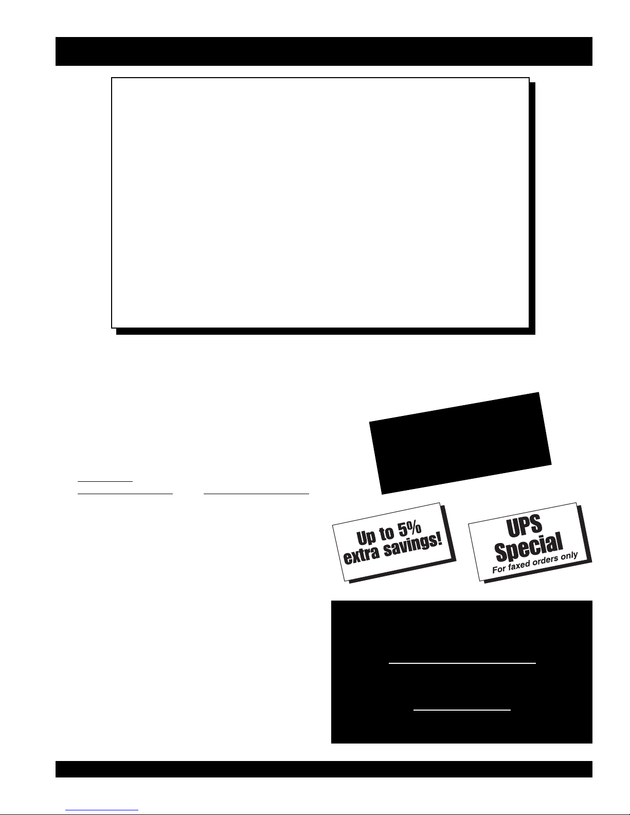
Earn Extra Discounts when
you order by FAX!
All parts orders which include complete part numbers
and are received by fax qualify for the following extra
discounts:
Number of
line items ordered Additional Discount
1-9 items 3%
10+ items** 5%
Get special freight allowances
when you order 10 or more
line items via FAX!**
■■
■
UPS Ground Service at no charge for freight
■■
■■
■
UPS Third Day Service at one-half of actual freight
■■
cost
Extra Fax DiscountExtra Fax Discount
Extra Fax Discount
Extra Fax DiscountExtra Fax Discount
for Domestic USAfor Domestic USA
for Domestic USA
for Domestic USAfor Domestic USA
Dealers OnlyDealers Only
Dealers Only
Dealers OnlyDealers Only
Now! Direct TOLL-FREE access
to our Parts Department!
Toll-free nationwide:
No other allowances on freight shipped by any other carrier.
**Common nuts, bolts and washers (all items under $1.00 list price)
do not count towards the 10+ line items.
*DISCOUNTS ARE SUBJECT TO CHANGE*
Fax order discount and UPS special programs revised June 1, 1995
FCG1 CONCRETE SAW — OPERATION & PARTS MANUAL — REV. #1 (10/08/02) — PAGE 5
800-421-1244
Toll-free FAX:
800/6-PARTS-7 • 800-672-7877
FCG1 CONCRETE SAW— SAFETY MESSAGE ALERT SYMBOLS
FOR YOUR SAFETY AND THE SAFETY OF OTHERS!
Safety precautions should be followed at all times when operating
this equipment. Failure to read and understand the Safety
Messages and Operating Instructions could result in injury to
yourself and others.
HAZARD SYMBOLS
NOTE
This Owner's Manual has been developed to provide
complete instructions for the safe and efficient operation
of the MQ Whiteman FCG1 CONCRETE SAW. For
engine maintenance information, please refer to the
engine manufacturers instructions for data relative to its
safe operation.
Before using this CONCRETE SAW, ensure that the
operating individual has read and understands all
instructions in this manual.
SAFETY MESSAGE ALERT SYMBOLS
The three (3) Safety Messages shown below will inform you
about potential hazards that could injure you or others. The
Safety Messages specifically address the level of exposure to
the operator, and are preceded by one of three words: DANGER,
WARNING, or CAUTION.
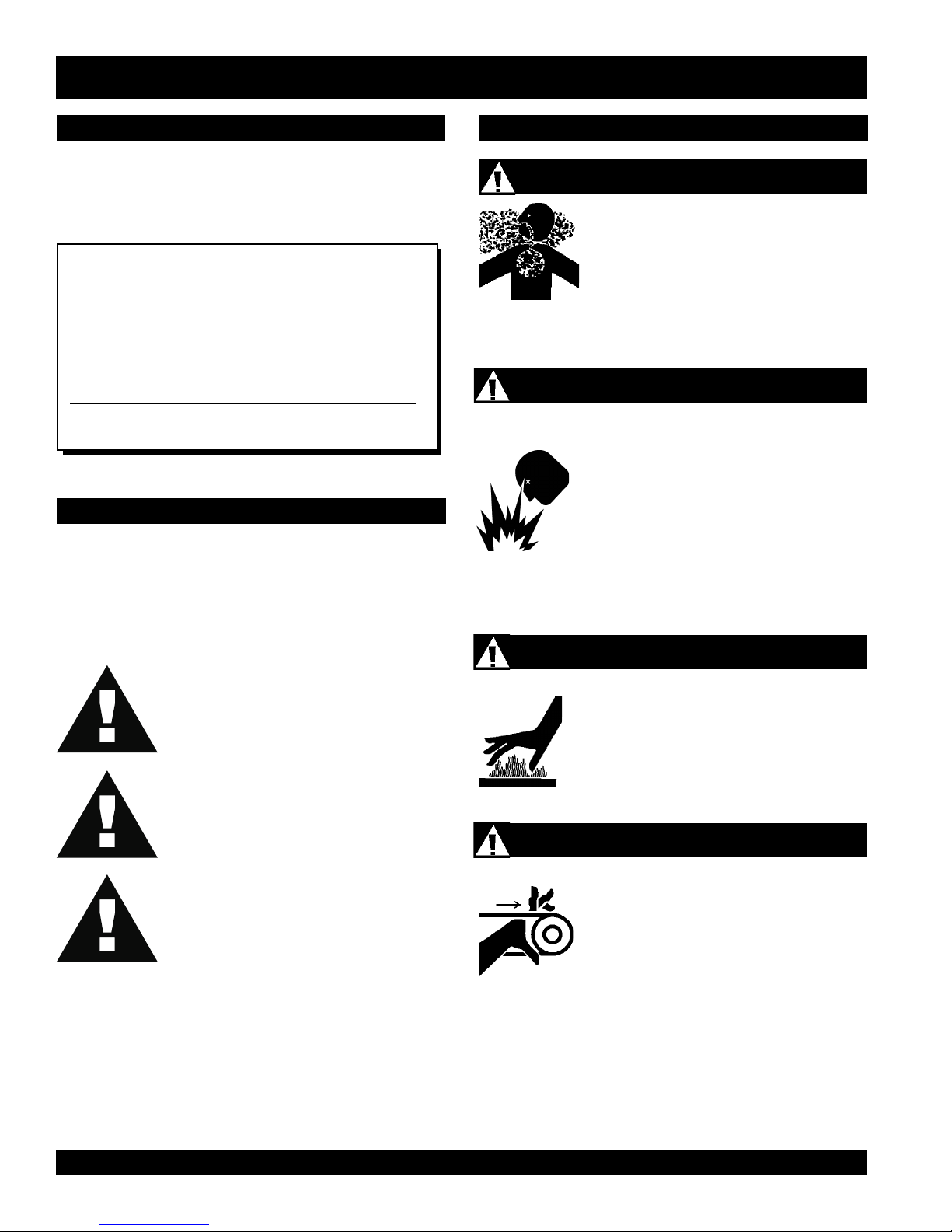
Lethal Exhaust Gases
Engine exhaust gases contain poisonous
carbon monoxide. This gas is colorless and
odorless, and can cause death if inhaled.
NEVER operate this equipment in a confined
area or enclosed structure that does not
provide ample free flow air.
Explosive Fuel
Gasoline is extremely flammable, and its
vapors can cause an explosion if ignited. DO
NOT start the engine near spilled fuel or
combustible fluids. DO NOT fill the fuel tank
while the engine is running or hot. DO NOT
overfill tank, since spilled fuel could ignite if it
comes into contact with hot engine parts or
sparks from the ignition system. Store fuel in
approved containers, in well-ventilated areas
and away from sparks and flames. NEVER
use fuel as a cleaning agent.
DANGER: You WILL be KILLED or
SERIOUSLY injured if you DO NOT follow
directions.
WARNING: You CAN be KILLED or
SERIOUSLY injured if you DO NOT follow
directions.
CAUTION: You CAN be injured if you
DO NOT follow directions.
Potential hazards associated with FCG1 Concrete Saw operation
will be referenced with "
throughout this manual, and will be referenced in conjunction
with Safety "
Message Alert Symbols
Hazard Symbols
".
" which appear
Burn Hazards
Engine components can generate extreme heat.
To prevent burns, DO NOT touch these areas
while the engine is running or immediately after
operations. NEVER operate the engine with
heat shields or heat guards removed.
Rotating Parts
NEVER operate equipment with covers, or
guards removed. Keep
and
clothing
prevent injury.
fingers, hands, hair
away from all moving parts to
PAGE 6 — FCG1 CONCRETE SAW— OPERATION & PARTS MANUAL — REV. #1 (10/08/02)
FCG1 CONCRETE SAW— SAFETY MESSAGE ALERT SYMBOLS
Accidental Starting
ALWAYS place the engine ON/OFF
switch in the OFF position, when the saw
is not in use.
Over Speed Conditions
NEVER tamper with the factory settings of the
engine governor or settings. Personal injury
and damage to the engine or equipment can
result if operating in speed ranges above
maximum allowable.
Guards and Covers In Place
NEVER operate the saw without blade guards
and covers in place. Adhere to safety
guidelines ANSI American National
Standards Institute, OSHA or other applicable
local regulations.
Respiratory Hazard
ALWAYS wear approved respiratory protection.
Sight and Hearing hazard
ALWAYS wear approved eye and hearing
protection.
Equipment Damage Messages
Other important messages are provided throughout this manual
to help prevent damage to your concrete saw, other property, or
the surrounding environment.
Rotating Blade
NOTE
Rotating blade can cut and crush. Keep
hands and feet clear.
This
concrete saw
, other property,
or the surrounding environment
could be damaged if you do not
follow instructions.
FCG1 CONCRETE SAW — OPERATION & PARTS MANUAL — REV. #1 (10/08/02) — PAGE 7
FCG1 CONCRETE SAW— RULES FOR SAFE OPERATION
■
CAUTION:
Failure to follow instructions in this manual
may lead to serious injury or even death! This
equipment is to be operated by trained and
qualified personnel only! This equipment is
for industrial use only.
The following safety guidelines should always be used when
operating the FCG1 Concrete Saw.
SAFETY
■
DO NOT operate or service this equipment
before reading this entire manual.
■
This equipment should not be operated by persons under 18
years of age.
■
NEVER operate the saw without proper protective
clothing, shatterproof glasses, steel-toed boots
and other protective devices required by the job.
NEVER touch the hot exhaust
manifold, muffler or cylinder. Allow
these parts to cool before servicing
the saw.
■
High Temperatures – Allow the engine to cool before adding
fuel or performing service and maintenance functions. Contact
hot!
with
■
The engine of this saw requires an adequate free flow of
cooling air. NEVER operate the saw in any enclosed or narrow
components can cause serious burns.
area where free flow of the
air is restricted. If the air flow
is restricted it will cause
serious damage to the saw's
engine and may cause injury
to people. Remember the
saw's engine gives off
DEADLY
gas.
carbon monoxide
■
■
NEVER operate this equipment when not
feeling well due to fatigue, illness or taking
medicine.
■
NEVER operate the saw under the
influence or drugs or alcohol.
■
NEVER use accessories or attachments, which are not
recommended by Multiquip for this equipment. Damage to
the equipment and/or injury to user may result.
■
Manufacturer does not assume responsibility for any accident
due to equipment modifications. Unauthorized equipment
modification will void all warranties.
■
Whenever necessary, replace nameplate, operation and
safety decals when they become difficult read.
■
ALWAYS check the saw for loosened threads or bolts before
starting.
■
■
■
■
■
ALWAYS refuel in a well-ventilated area, away from sparks
and open flames.
ALWAYS use extreme caution when
working with flammable liquids. When
refueling, stop the engine and allow it
to cool.
NEVER
machine. Fire or explosion could result from
fuel vapors
engine.
NEVER operate the saw in an explosive atmosphere where
fumes are present or near combustible materials. An explosion
or fire could result causing severe
smoke
around or near the
, or if fuel is spilled on a
hot!
bodily harm or even
death.
Topping-off to filler port is dangerous, as it tends to spill fuel.
NEVER use fuel as a cleaning agent.
PAGE 8 — FCG1 CONCRETE SAW— OPERATION & PARTS MANUAL — REV. #1 (10/08/02)
FCG1 CONCRETE SAW— RULES FOR SAFE OPERATION
GENERAL SAFETY
■
ALWAYS read, understand, and follow procedures in
Operator's Manual before attempting to operate equipment.
■
ALWAYS be sure the operator is familiar with proper safety
precautions and operating techniques before using the saw.
■
NEVER leave the machine
■
Block the unit when leaving or when using on a slope.
■
ALWAYS check to make sure that the operating area is clear
before starting the engine.
■
Maintain this equipment in a safe operating condition at all
times.
■
ALWAYS stop the engine before servicing, adding fuel and
oil.
■
NEVER run the engine without the air filter. Severe engine
damage could occur.
■
ALWAYS service air cleaner frequently to prevent carburetor
malfunction.
■
AVOID wearing jewelry or loose fitting clothing that may snag
on the controls or moving parts, this can cause a serious
injury.
■
ALWAYS keep clear of
operating or the saw.
■
ALWAYS store equipment properly when it is not being used.
Equipment should be stored in a clean, dry location out of
the reach of children.
■
NEVER use accessories or attachments which are not
recommended by the manufacturer for this equipment.
Damage to the equipment and/or injury to user may result.
unattended
rotating
or
while running.
moving parts
while
WARNING
■
ALWAYS check to make sure that the
operating area is clear before starting the
engine.
■
Keep all inexperienced and unauthorized people away from
the equipment at all times.
DIAMOND BLADE SAFETY
■
■
■
■
■
■
■
■
■
SAW TRANSPORTATION SAFETY
■
■
■
■
■
Use appropriate steel centered diamond blades
manufactured for use on concrete saws.
Always inspect diamond blades before each use. The blade
should exhibit no cracks, dings, or flaws in the steel centered
core and/or rim. Center (arbor) hole must be undamaged
and true.
Examine blade flanges for damage, excessive wear and
cleanliness before mounting blade. Blade should fit snugly
on the shaft and against the inside/outside blade flanges.
Ensure the blade is marked with an operating speed greater
than the blade shaft speed of the saw.
Only cut the material that is specified by the diamond blade.
Read the specifications of the diamond blade to ensure the
proper tool has been matched to the material being cut.
Always keep blade guards in place. Exposure of the diamond
blade must not exceed 180 degrees.
Ensure that the diamond blade does not come into contact
with the ground or surface during transportation. DO NOT
drop the diamond blade on ground or surface.
The engine governor is designed to permit maximum engine
speed in a no-load condition. Speeds that exceed this limit
may cause the diamond blade to exceed the maximum safe
allowable speed.
Ensure that the blade is mounted for proper operating
direction.
Use the lifting handle and/or the appropriate lifting equipment
to ensure the safe movement of the saw.
DO NOT use the handle bars and/or front pointer as lifting
points.
NEVER attempt to tow the untrailered saw behind a vehicle.
Do not use on slopes or on extremely unlevel surfaces. An
engine tipped to extreme angles may cause oil to gravitate
into the cylinder head making the engine difficult to start.
NEVER transport the saw with the blade mounted.
FCG1 CONCRETE SAW — OPERATION & PARTS MANUAL — REV. #1 (10/08/02) — PAGE 9
FCG1 CONCRETE SAW— RULES FOR SAFE OPERATION
EMERGENCIES
■
ALWAYS know the location of
the nearest
■
ALWAYS know the location of the
nearest and
■
In emergencies
nearest phone or
Also know the phone numbers of the nearest
ambulance, doctor
information will be invaluable in the case of an
emergency.
fire extinguisher
first aid kit
always
keep a phone on the job site
and
.
.
know the location of the
.
fire department
. This
PAGE 10 — FCG1 CONCRETE SAW— OPERATION & PARTS MANUAL — REV. #1 (10/08/02)
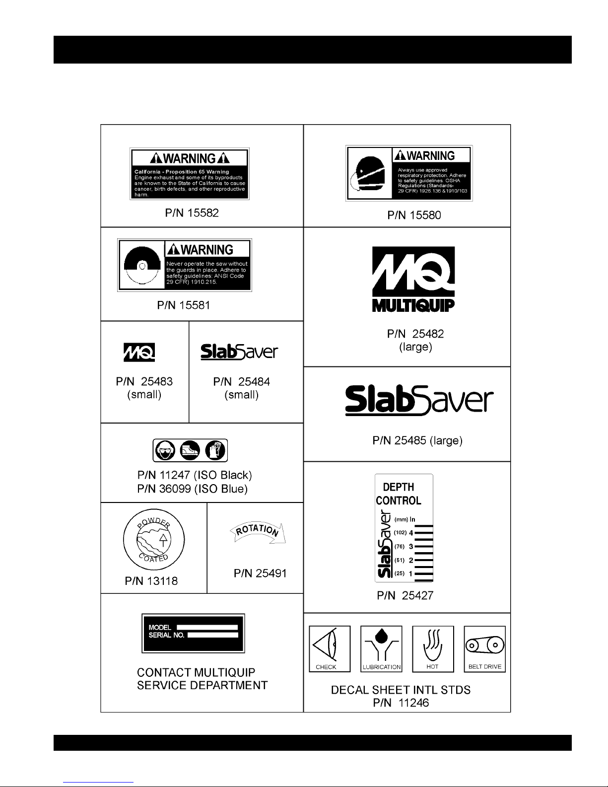
FCG1 CONCRETE SAW— OPERATION AND SAFETY DECALS
Machine Operation And Safety Decals
The FCG1 Concrete Saw is equipped with a number of safety decals. These decals are provided for operator safety and maintenance
information. Should any of these decals become unreadable, replacements can be obtained from your dealer.
FCG1 CONCRETE SAW — OPERATION & PARTS MANUAL — REV. #1 (10/08/02) — PAGE 11
Figure 1. FCG1 Concrete Saw Decals
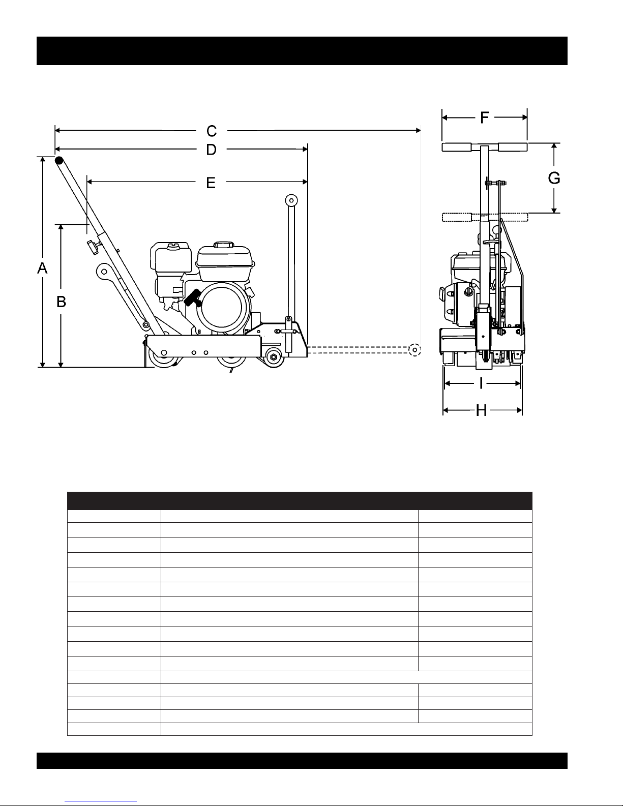
FCG1 CONCRETE SAW— SPECIFICATIONS (SAW)
A
B
C
D
E
F
G
H
Side View
Front View
Figure 2. FCG1 Concrete Saw Dimensions
snoitacificepSwaSetercnoC1GCF.1elbaT
RETTELECNEREFER NOITPIRCSED )MC(NOISNEMID
)desiaRylluFsraBeldnaH(thgieHxaM
)derewoLylluFsraBeldnaH(thgieHxaM
)derewoLretnioPtnorF&desiaRylluFsraBeldnaH(htgneLxaM
)desiaRretnioPtnorF&desiaRylluFsraBeldnaH(htgneLxaM )MC9.121(.nI84
)desiaRretnioPtnorF&derewoLylluFsraBeldnaH(htgneLxaM )MC99(.nI93
)1etoNees(htdiWllarevOxaM )MC3.43(.nI5.31
noitcelfeDraBeldnaHxaM )MC5.73(.nI57.41
esaBleehWtnorF )MC1.13(.nI52.21
I
1etoN
esaBleehWraeR )MC9.92(nI57.11
devomereldnahdnasretniopraerdnatnorfhtiwderusaemhtdiW
)HxWxL(noisnemiDdetarC )MC4.85xMC3.43xMC6.78(.nI32x.nI5.31x.nI5.43
ENIGNESSEL,1GCF,WAS ).gk43.241(.bL7.46
NIBORph0.7/ADNOHph5.6,1GCF,WAS )gK022(.bL001
)gk033(.bL051thgieWdetarC
)MC7.811(.nI57.64
)MC3.18(.nI0.23
)MC7.271(.nI86
)GK(THGIEW
PAGE 12 — FCG1 CONCRETE SAW— OPERATION & PARTS MANUAL — REV. #1 (10/08/02)

FCG1 CONCRETE SAW— SPECIFICATIONS (ENGINE)
)enignE(snoitacificepS.2elbaT
ledoM9CXQ002XGADNOH12XENIBOR
epyT
ekortSXeroB
tnemecalpsiD)cc691(.ni-uc0.21)cc112(.ni-uc78.21
tuptuOxaM
enignE
yticapaCknaTleuF
leuF
yticapaCliOebuL)retil06.0(tqSU36.0)retil06.0(tqSU426.0
lortnoCdeepS
dohteM
dohteMgnitratStratSlioceRtratSlioceR
)sretiL6.3(
elgniS,ekorts4delooc-riA
enignEenilosaG,VHO,rednilyC
.ni1.2X.ni7.2
)mm45xmm86(
.M.P.R0063/.P.H4.6
)SP5.6,Wk8.4(
snollaG.S.U59.0.xorppA
)sretiL6.3(
enilosaGelibomotuAdedaelnU
rengihroenatcO68
epyTthgiew-ylFlagufirtneCepyTthgiew-ylFlagufirtneC
elgniS,ekorts4delooc-riA
enignEenilosaG,VHO,rednilyC
.ni63.2X.ni46.2
)mm06xmm76(
.M.P.R0004/.P.H0.7
)SP0.7,Wk1.5(
snollaG.S.U59.0.xorppA
enilosaGelibomotuAdedaelnU
rengihroenatcO68
noisnemiD
)HxWxL(
yrD
thgieWteN
FCG1 CONCRETE SAW — OPERATION & PARTS MANUAL — REV. #1 (10/08/02) — PAGE 13
.ni2.31X8.41x3.21
)mm533X673X313(
).gK61(sbl3.53).gK61(sbl82.53
.ni91.31X4.41x42.21
)mm533X663X113(

FCG1 CONCRETE SAW—FAMILIARIZATION/ CONTROLS & COMPONENTS
FAMILIARIZATION
This FCG1-6H SlabSaver Saw is designed for wet or dry sawing
of concrete slabs utilizing diamond blades. The saw has been
engineered for general and industrial flat sawing applications
that include: Joint Sawing of Green Concrete, Decorative
Sawing in Cured Concrete, Light Demolition Sawing and "V"
CONTROLS & COMPONENTS
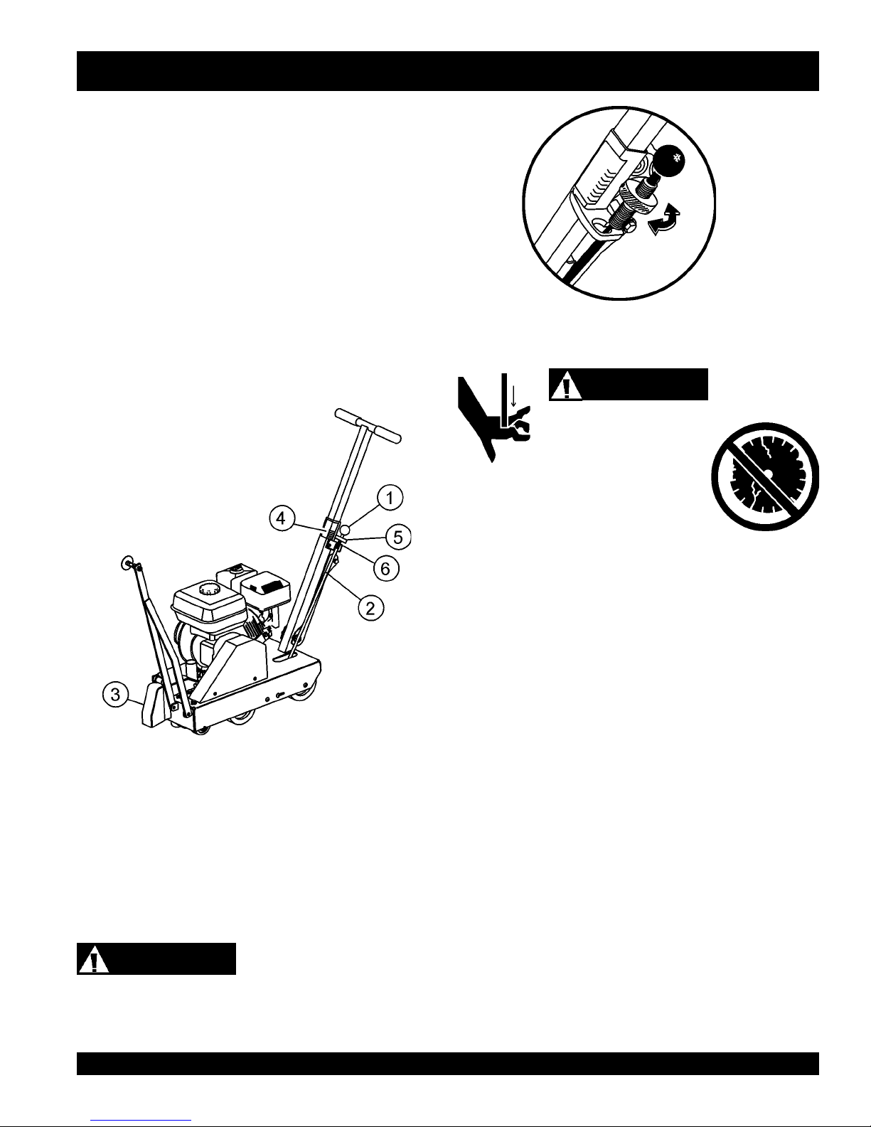
Figures 3 shows the location of the basic controls or components,
for the FCG1 Concrete Saw. Listed below is a brief explanation
of each control or component
1. Hand Grips/Handlebar – When operating the saw, place
both hands on each grip to maneuver the saw.
Groove Beveling. The simple and compact nature of the
SlabSaver makes it a perfect sawing tool for one person to
operate and transport. The saw combines innovative features,
top quality components, and a committed attention to state-ofthe-art manufacturing.
For peak performance, the SlabSaver has been engineered to
operate a powerful 6.5 HP Gasoline engine and 10" diameter
diamond blades. This special design allows for fast/clean cuts
2. Adjustable Handle – Set to comfortable operating position.
3. Rear Guide – Rear guide wheel drops into cut to assist in
straight tracking.
4. Air Filter – Prevents dirt and debris from entering the engine
air intake. Keep cleaned and replace when necessary.
5. Recoil Starter Handle – Pull to engage and start the
engine.
in different materials at depths from 1/4" to 3 1/4".
For maximum performance and return on investment use:
6. Recoil Starter Assembly – Engages the engine when
the handle is pulled and rewinds the starter rope when the
handle is released.
7. Wheels/Carraige Assembly – Heavy-duty polyurethane
wheels with permanently sealed ball bearings.
Diamond Blades.
The jig-welded reinforced heavy gauge steel frame and chassis
assembly are designed to eliminate operational bending and/or
flex that would lead to diminished blade performance. Also, the
frame's general weight-to-strength ratio and center mounted
blade design ensure accurate tracking in the cut.
A robust blade shaft bearing assembly ensures minimal flutter
and shaft harmonics providing the most advantageous
conditions for a diamond blade at operating speeds.
Heavy-duty front and rear axles, polyurethane wheels with
permanently sealed ball bearings, and solid undercarraige
assembly provide years of reliable use. The SlabSaver
incorporates an innovative PosiLok raise/lower control assembly
that provides fingertip control of blade orientation, infinitely
adjustable locking blade depth control, and depth feed gauge.
Retractable front & rear pointers with "tracking wheels" are
provided to support precise straight sawing. This system permits
the operator to quickly adjust the blade cutting depth and
safeguard against "blade-creep" during sawing operations. For
operator comfort and ease of transportation & storage, an
adjustable locking handle bar is provided.
Operator control of the saws is safely accomplished with
adjustable handle bars, and a conveniently oriented raise/lower
lever and depth adjustment wheel.
ENGINE
Pages 22-24 highlight fundamental aspects of engine inspection
and starting. Refer to the engine Owner's Manual for specific
instructions regarding operation, service and maintenance.
PAGE 14 — FCG1 CONCRETE SAW— OPERATION & PARTS MANUAL — REV. #1 (10/08/02)
8. Diamond Blade – 10" blade capacity. 10" diameter
provides for 1/4" to 3 1/4" depth of cut.
9. Blade Guard – Covers saw blade and flips up to allow
blade to be changed.
10. Belt Tension Adjuster – Adjusts belt tension.
11. Front Pointer – Assists in straight tracking.
12. Front Pointer Arm – Stows up for storage and pivots down
for use.
13. Depth Adjust Disk – Turn disk clockwise or counterclockwise to adjust the cutting depth up or down.
14. Fuel Tank – Use unleaded gasoline. Do not overfill.
15. Shift Knob – Moves Depth Stop Rod in or out of keyhole
slot.
16. V-Belt Cover – Remove this cover to gain access to the Vbelt. NEVER operate the saw with this cover removed.
17. Arbor Shaft Grease Zerks – Conveniently located for
lubrication.
18. On/Off Switch – Turn to the "ON" position to allow engine
to be started and turn to the "OFF" position to shut the
engine off.
19. Handle Lock – Lock handle height to a comfortable
operating position.
20. Screw Plunger – Line up bottom edge of Depth Stop Rod
on Screw Plunger across from desired depth line mark.
21. Depth Stop Rod – Holds blade above working surface or
allows blade to cut into working surface at specified depth.
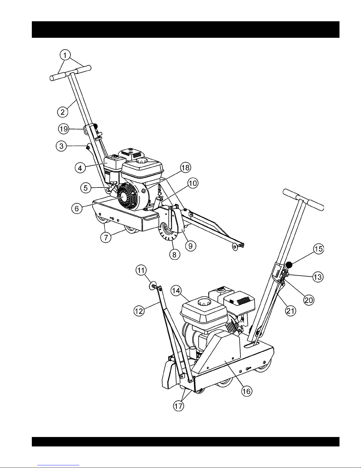
FCG1 CONCRETE SAW—FAMILIARIZATION/ CONTROLS & COMPONENTS
FCG1 CONCRETE SAW — OPERATION & PARTS MANUAL — REV. #1 (10/08/02) — PAGE 15
Figure 3. FCG1 Concrete Saw
(HONDA ENGINE SHOWN)
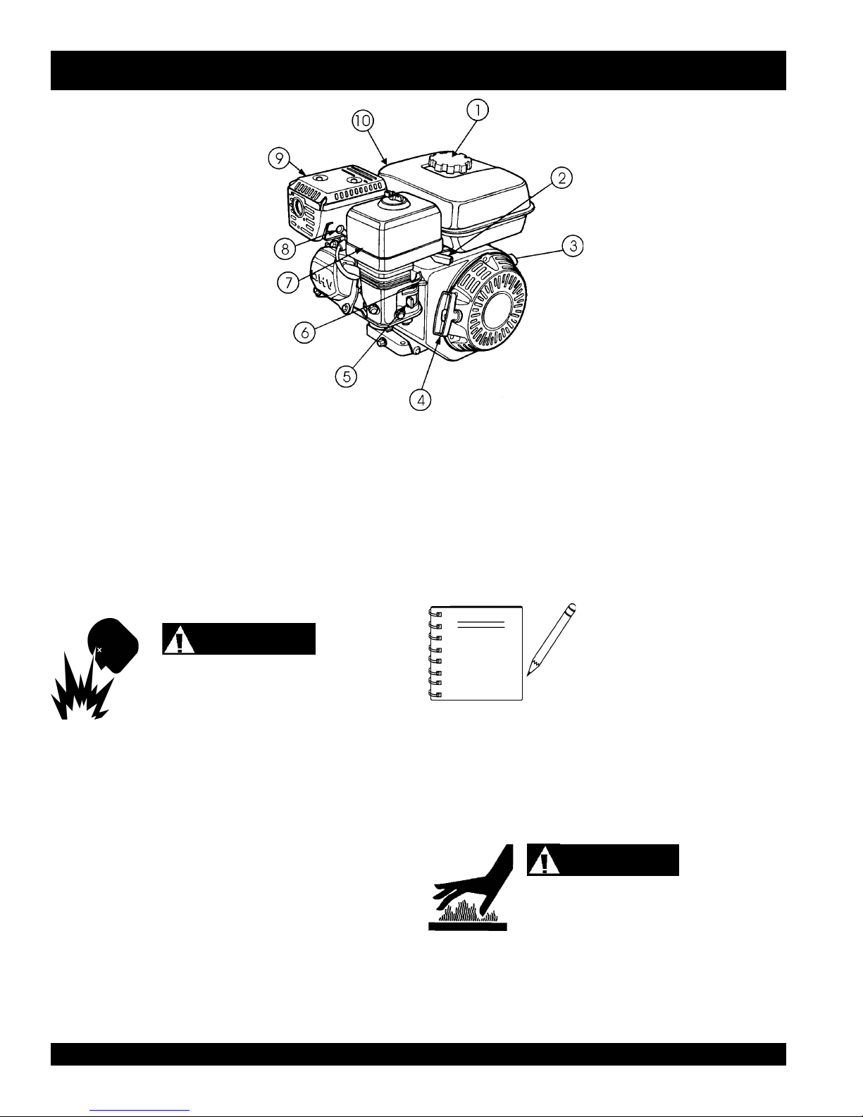
FCG1 CONCRETE SAW— BASIC ENGINE
Figure 4. Engine Controls and Components
INITIAL SERVICING
The engine (Figure 4) must be checked for proper lubrication and
filled with fuel prior to operation. Refer to the manufacturers engine
manual for instructions & details of operation and servicing.
1. Fuel Filler Cap – Remove this cap to add unleaded
gasoline to the fuel tank. Make sure cap is tightened
securely. DO NOT over fill.
DANGER
Adding fuel to the tank should be done only when
the engine is stopped and has had an opportunity
to cool down. In the event of a fuel spill, DO NOT attempt to start the
engine until the fuel residue has been completely wiped up, and the
area surrounding the engine is dry.
2. Throttle Lever – Used to adjust engine RPM speed (lever
advanced forward
FAST
).
3. Engine ON/OFF Switch – ON position permits engine
starting, OFF position stops engine operations.
4. Recoil Starter (pull rope) – Manual-starting method. Pull
the starter grip until resistance is felt, then pull briskly and
smoothly.
5. Fuel Valve Lever – OPEN to let fuel flow, CLOSE to stop
the flow of fuel.
SLOW
, lever back toward operator
6. Choke Lever – Used in the starting of a cold engine, or in
cold weather conditions. The choke enriches the fuel
mixture.
7. Air Cleaner – Prevents dirt and other debris from entering
the fuel system. Remove wing-nut on top of air filter
cannister to gain access to filter element.
NOTE
8. Spark Plug – Provides spark to the ignition system. Set
spark plug gap to 0.6 - 0.7 mm (0.028 - 0.031 inch) Clean
spark plug once a week.
9. Muffler – Used to reduce noise and emissions.
operating. NEVER operate the engine with the muffler removed.
10. Fuel Tank – Holds unleaded gasoline. For additional
information refer to engine owner's manual.
Operating the engine without an air
filter, with a damaged air filter, or a
filter in need of replacement will
allow dirt to enter the engine, causing
rapid engine wear.
WARNING
Engine components can generate extreme heat.
To prevent burns, DO NOT touch these areas
while the engine is running or immediately after
PAGE 16 — FCG1 CONCRETE SAW— OPERATION & PARTS MANUAL — REV. #1 (10/08/02)
FCG1 CONCRETE SAW — GUARDS, COVERS AND V-BELTS
WARNING
NEVER operate the saw without blade guards
and covers in place. DO NOT operate with
the front of the blade guard raised. The blade
exposure cannot exceed 180 degrees during
operation. Adhere to the safety guidelines of
the American National Standards Institute
(ANSI) B7.1 and B7.5.
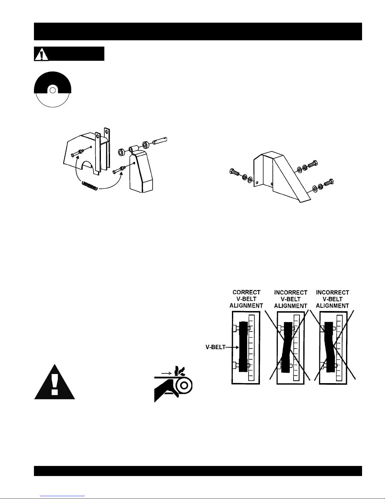
Figure 5. Blade Guard
CHECK the following on the"blade guard" (Figure 5):
V-belt Alignment and Tensioning
This concrete saw is equipped with a premium V-belt that has
been aligned and tensioned by factory personnel. The V-belt
must be aligned and tensioned for proper operation of the saw.
Use the following procedure to check the alignment of V-belt:
1. Remove the bolts that secure the V-belt cover (Figure 6) to
the saw frame.
Figure 6. V-Belt Cover
■
Ensure the capacity of the blade guard matches the diameter
of your diamond blade.
■
Check that the guard is bolted firmly upon the saw frame.
■
Check that the spring tensioned front cover of the guard is
firmly seated with the rear section of the guard, and there are
no gaps. NEVER lift the blade guard while cutting.
V-belt Check
A worn or damaged V-belt can adversely affect the performance
of the saw. If the V-belt is defective or worn, replace and the V-belt
as outlined on page 19.
CAUTIONCAUTION
CAUTION
CAUTIONCAUTION
NEVER attempt to check
the V-belt with the engine
running. Severe injury can
occur. Keep fingers, hands,
hair and clothing away from
all moving parts.
2. Check uniform parallelism (Figure 7) of V-belt and pulley
3. Check V-belt tension by using a tension meter (6.0 - 9.0 lbs.)
(sheaves). Use a straight-edge or machinist's square against
both pulleys and adjust both pulleys until equally aligned.
Figure 7. Pulley Alignment
against the inside belt at a mid point between the two pulleys,
or by deflecting the center belt at a mid point 3/8" (10 mm) to
1/2" (13 mm). See Figure 8.
FCG1 CONCRETE SAW — OPERATION & PARTS MANUAL — REV. #1 (10/08/02) — PAGE 17
FCG1 CONCRETE SAW — GUARDS, COVERS AND V-BELTS
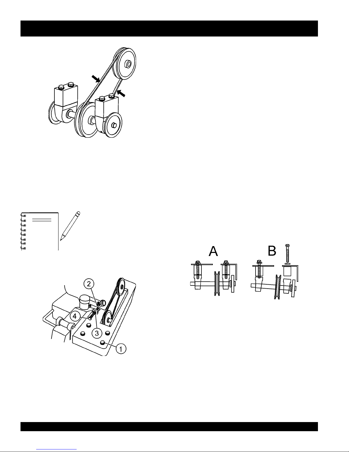
3. Tighten the adjusting hex screw (4) while holding the engine
in place to maintain pulley alignment. (a screwdriver can be
used as a lever at the rear belt guard mounting boss to hold
the back of the engine while adjusting V-belt tension.)
4. Re-tighten the locking nut (3).
5. With V-belt held in proper alignment, (engine parallel with
the frame), re-tighten the 4 engine mounting hex screws.
Verify that all hex screws are properly tightened.
To Remove and Replace the V-belt:
Figure 8. V-Belt Tension Check
4. DO NOT over or under tighten the V-belt. Severe damage
can occur to the saw and engine crank shaft if the belt is
over-tensioned. A decrease of power to the blade and poor
performance will result if the belt is under-tensioned (loose
on pulleys).
V-belt alignment must be
NOTE
To Tighten the V-belt:
rechecked after adjusting belt
tension.
If the V-belt become worn or damaged, replace it with P/N 15082
(Gates/Optibelt 3VX335).
1. Remove the 3 hex screws holding the V-belt guard and
remove the guard.
2. Loosen the 4 engine mounting hex screws. (item 2, Figure 9)
3. Loosen locking nut on the V-belt tension adjuster (item 3,
Figure 9). Loosen the tension on the V-belt by turning the
tension adjuster hex screw (item 4, Figure 9).
4. Pull the engine ahead to provide slack in the V-belt.
5. Loosen the 4 arbor shaft hex screws, (item 1, Figure 9).
Figure 10. V-Belt Removal
Figure 9. V-Belt Tension Adjust
1. With V-belt guard removed, loosen the 4 engine mounting
hex screws. (items 2 Figure 9)
2. Loosen locking nut on the V-belt tension adjuster, (3 ).
PAGE 18 — FCG1 CONCRETE SAW— OPERATION & PARTS MANUAL — REV. #1 (10/08/02)
6. Remove the two outer arbor shaft hex screws allowing the
outside of the shaft to drop, (B in Figure 10), allowing removal
of the V-belt.
7. Reinstall new V-belt.
8. Re-install and tighten arbor shaft hex head screws.
9. With V-belt held in proper alignment, re-tighten the 4 engine
mounting hex screws. (Follow V-belt tightening procedures.)
10. Re-install belt guard with 3 hex screws.
FCG1 CONCRETE SAW — BLADES
SAW BLADES
For maximum performance and return on investment use:
Diamond Blades.
Saw blades, or cutting disks are available in either an abrasive
design or as diamond blades. Either blade will work on the
FCG1 Concrete Saw, however, diamond blades are
recommended. Diamond blades are available specifically
designed for cutting green concrete, cured concrete, asphalt, as
well as a "V-Cut" blade use for decorative work. Ask your dealer
about your specific cutting application.
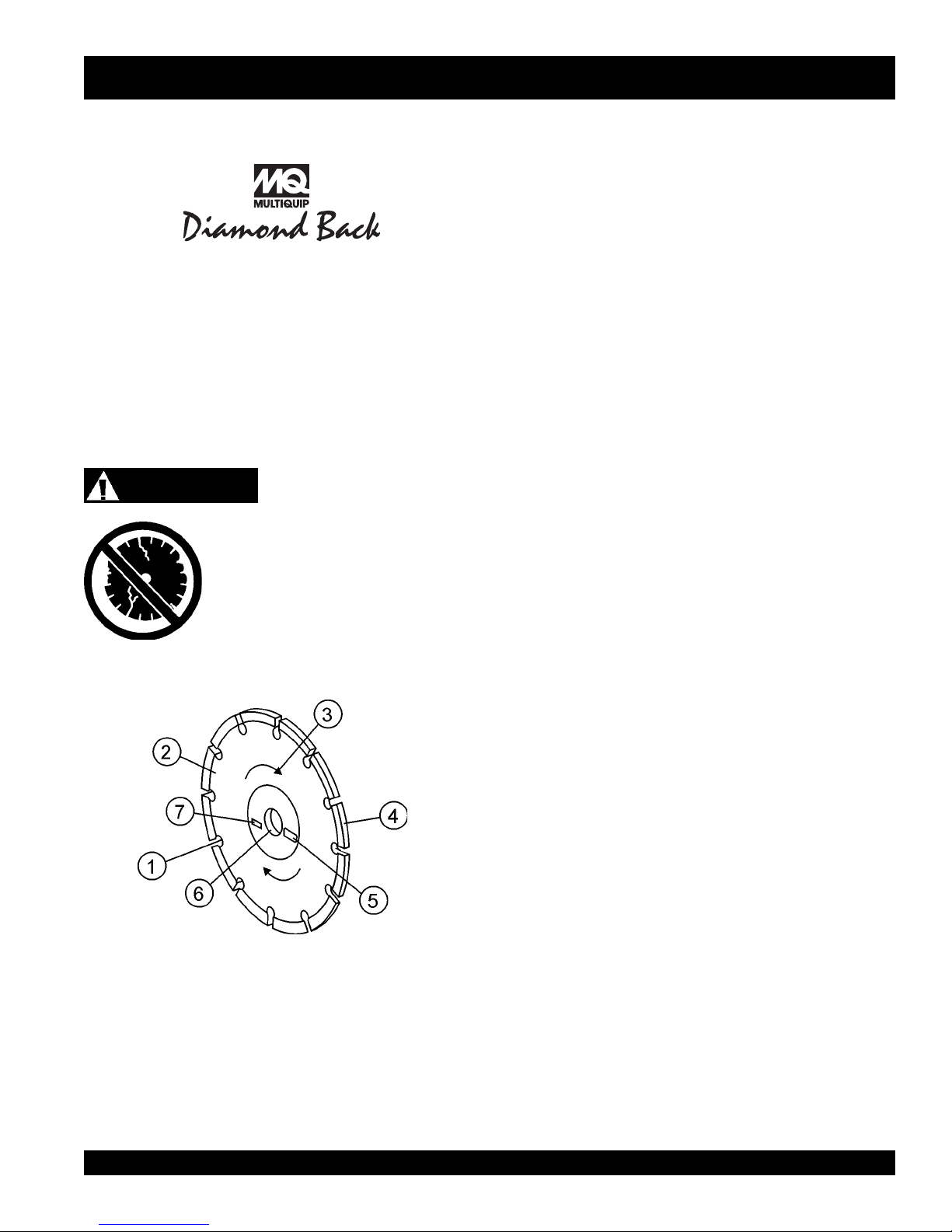
SAW BLADE INSPECTION
2. Edge of the Steel Core - Check the diameter edge for
discoloration (blue oxidation) indicating an overheating
condition caused by insufficient cooling water/air.
Overheating of blades may lead to loss of core tension and/
or increase the possibility for blade failure. Make sure the
steel core's width is uniform about the rim of the blade, and
not succumbing to an "under-cutting" condition brought
about by highly abrasive material or improper under-cutting
core protection.
3. Directional Arrow - Ensure that the blade is oriented
properly on the blade shaft for sawing. Reference the
directional arrow on the blade and place it so the direction
of rotation "downcuts" with the turn of the shaft.
4. Diamond Segment or Rim - Ensure there are no cracks,
dings, or missing portions of the diamond segment/rim. DO
NOT
of the rim.
WARNING
Failure to thoroughly inspect the diamond
blade (Figure 11) for operational safety
could result in damage to the blades or
the saw and may cause injury to the user
or others in the operating area.
cause damage to your saw or injury to the user or others in
the operating area.
5. Specifications - Ensure that the blade specifications, size,
and diameter properly match up to sawing operations. The
saw has been designed to saw DRY, using ambient air for
blade cooling. Utilizing a blade not matched properly to the
task may result in poor performance and/or blade damage.
use a blade that is missing a segment or a portion
Damaged and /or missing segments/rims may
6. Arbor Hole - It is essential that the arbor hole diamter
7. MAX RPM - This RPM reference is the maximum safe
Figure 11. Diamond Blade
1. Stress Relief Holes (Gullets) - Check the steel core for
cracks that may have propagated from the slots and/or
gullets. Cracks indicate extreme fatigue failure and if sawing
continues, catastrophic failure will occur.
properly matches the blade, and that it is free from distortion.
Correct blade flanges (collars) must be used. The inside
face of the flanges must be clean and free of debris. An outof-round arbor condition will cause damage to the blade
and the saw.
operating speed for the blade selected. NEVER exceed the
max RPM on the diamond blade. Exceeding the maximum
RPM is dangerous and may cause poor performance and
may damage the blade. Optimum operation of the FCG1
Concrete Saw is achieved with a 10" blade at 6000 RPM.
FCG1 CONCRETE SAW — OPERATION & PARTS MANUAL — REV. #1 (10/08/02) — PAGE 19
FCG1 CONCRETE SAW — BLADE PLACEMENT
WARNING
Failure to thoroughly inspect the diamond
blade for operational safety could result in
damage to the blades or the saw and may
cause injury to the user or others in the
operating area.
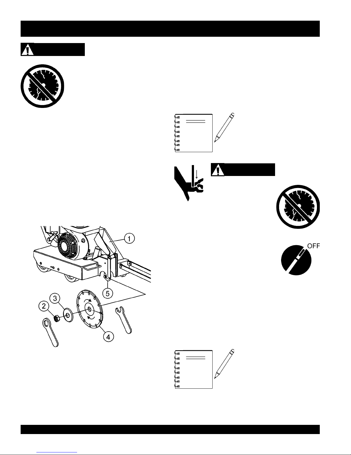
1. Blade Guard - Pivot the blade guard front cover all the way
back. The guard tension spring will keep the front cover in
position.
2. Blade Hex Nut - Unscrew the blade shaft nut (right side
loosens clockwise and tightens counter-clockwise while the
left side loosens counter-clockwise and tightens clockwise.
DO NOT overtighten the nut (approximately 45-50 ft. lb/6168 N/m) when finalizing the assembly.
3. Outside Blade Flange (Collar) - Ensure that the outside
blade flange is placed flush against the diamond blade.
The inside surface of the flange must be free of debris and
permit a tight closure on the surface of the blade core.
5. Inner Flange (Collar) - This flange is fixed upon the blade
Blade Selection
The FCG1 Concrete Saw has a capacity for a 10" blade. This
allows a cutting range from 0" to 3 1/4". Operating blade speed
is 6000 RPM.
damage the diamond blade and may
cause serious damage to the saw and
bodily harm.
shaft. The inside surface of the flange must be free of debris
and permit a tight closure on the surface of the blade.
NOTE
The following steps should be
accomplished before using the
FCG1 Saw on any cutting surface.
WARNING
Dropping or forcing the
blade onto the cutting
surface can severely
Blade Removal and Replacement
1. Set the engine ON/OFF switch to the
2. Place the FCG1 Saw on a stable level working surface.
3. Ensure the blade is raised and the raise/lower rod is locked
4. Raise the blade by appling a downward pressure on the
Figure 12. Diamond Blade Placement
4. Diamond Blade - Ensure that the proper diamond blade
has been selected for the job. Pay close attention to the
directional arrows on the blade. The blade's operating
directional arrows must point in a "down-cutting" direction
to perform correctly. When placing the blade onto the blade
shaft, ensure the arbor hole of the blade matches the
diameter of the shaft.
5. Lift up the blade guard cover (item 1 Figure 12) to gain
"OFF" position.
into position.
handlebars to raise the blade and allow the raise/lower rod
to drop into the "raised-position" slot.
When removing or installing a
NOTE
access to the diamond blade.
diamond blade, please note that the
blade retaining nuts are left and righthand threaded.
PAGE 20 — FCG1 CONCRETE SAW— OPERATION & PARTS MANUAL — REV. #1 (10/08/02)
FCG1 CONCRETE SAW — BLADE PLACEMENT
6. Use the provided blade nut and blade shaft locking
wrenches (Figure 12) to install the diamond blade.
Reference items 1 - 5 and Figure 12 on page 20.
■
While holding the blade shaft with the locking wrench,
remove the blade hex nut (clockwise direction) and outer
blade flange.
■
Remove the old blade and install a new blade in the
same rotational direction as marked on the blade.
■
Reinstall the outer blade flange and hex nut. Tighten
the nut firmly (counter-clockwise direction). DO NOT
OVER TIGHTEN.
Cutting Depth Adjustment
The FCG1 Saw is equipped with a Raise/Lower Assembly that
is supported by the following components (Figure 13).
damage the diamond blade and may
cause serious damage to the saw and
bodily harm.
Figure 14. Raise/Lower Adjustment Wheel
WARNING
Dropping or forcing the
blade onto the cutting
surface can severely
Figure 13. Raise/Lower Assembly
(1) Shift Knob
(2) Depth Stop Rod
(3) Blade Guard
(4) Depth Control Indicator
(5) Depth Adjust Disk
(6) Screw Plunger
WARNING
To adjust the blade to the desired cutting depth, perform the
following steps:
1. Mount the desired diamond blade on the shaft and secure
as instructed in the Blade Removal and Replacement
section.
2. While holding the handle bars to support the weight of the
saw, grasp the knob of the Depth Stop Rod and move it
forward out of its keyhole slot. (Figure 14)
3. Gently allow the blade to contact the surface.
4. Rotate the Depth Stop Disk about the Screw Plunger and
line up the
from desired depth line mark.. THIS LINE MARK WILL
COINCIDE WITH THE BLADE CUTTING DEPTH
REGARDLESS
5. Press down on the handlebars again to lift the blade until
the Depth Stop Rod drops into the back portion of the
keyhole slot.
6. You are ready to start cutting. Refer to the following preinspection and operation sections.
bottom edge
OF BLADE DIAMETER USED.
of the Depth Stop Disk across
ALWAYS be certain the engine ON/OFF switch is in the "OFF"
position and the blade shaft has COMPLETELY STOPPED
ROTATING before performing the following operations.
FCG1 CONCRETE SAW — OPERATION & PARTS MANUAL — REV. #1 (10/08/02) — PAGE 21
7. Test the depth of cut by cutting a short distance, then measure
the depth of the cut.
FCG1 CONCRETE SAW — INSPECTION — PRE-INSPECTION
Before Starting
1. Read safety instructions at the beginning
of manual.
saw,
2. Clean the
particularly the engine cooling air inlet, carburetor and air
cleaner.
3. Check the air filter for dirt and dust. If air filter is dirty, replace
air filter with a new one as required.
4. Check carburetor for external dirt and dust. Clean with dry
compressed air.
5. Check fastening nuts and bolts for tightness.
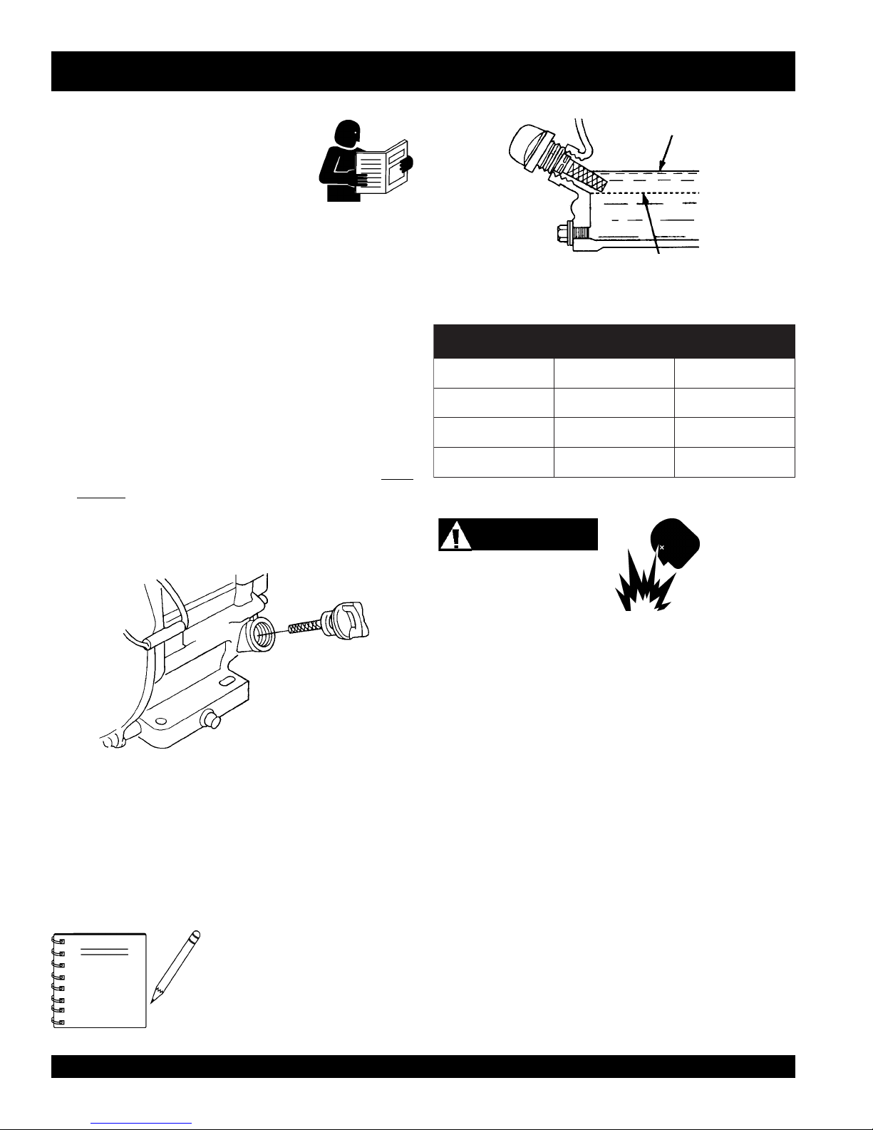
Engine Oil Check
1. To check the engine oil level, place the saw on secure level
ground with the engine stopped. The frame platform
be level
removing dirt and dust,
must
to accurately check the engine oil.
Figure 16. Engine Oil Dipstick (Oil Level)
epyTliO.3elbaT
nosaeS erutarepmeT epyTliO
remmuS rehgiHroC°52 03-W01EAS
llaF/gnirpS C°01~C°52 02/03-W01EAS
retniW rewoLroC°0 01-W01EAS
2. Remove the filler dipstick from the engine oil filler hole
(Figure 15) and wipe it clean.
Fuel Check
Motor fuels are highly flammable and can be dangerous if
mishandled. DO NOT smoke while refueling. DO NOT attempt
to refuel the trowel if the engine is
1. Remove the gasoline cap located on top of fuel tank.
Figure 15. Engine Oil Dipstick (Removal)
3. Insert and remove the dipstick without screwing it into the filler
neck. Check the oil level shown on the dipstick.
2. Visually inspect to see if fuel level is low. If fuel is low, replenish
with unleaded fuel.
3. When refueling, be sure to use a strainer for filtration. DO
NOT top-off fuel. Wipe up any spilled fuel.
4. If the oil level is low (Figure 16), fill to the edge of the oil filler
hole with the recommended oil type (Table 3).
V-belt Check
A worn or damaged V-belt can adversely affect the performance
of the trowel. If a V-belt is defective or worn, replace the V-belt as
outlined on page 18.
Blade Check
NOTE
Reference manufacturer engine
manual for specific servicing
instructions.
Check for worn or damaged blades. Refer to BLADE
PLACEMENT section on pages 20 - 21.
Explosive Fuel
hot! or running
.
PAGE 22 — FCG1 CONCRETE SAW— OPERATION & PARTS MANUAL — REV. #1 (10/08/02)
FCG1 CONCRETE SAW — INITIAL START-UP
CAUTIONCAUTION
CAUTION
CAUTIONCAUTION
CAUTIONCAUTION
CAUTION
CAUTIONCAUTION
ALWAYS wear approved eye and hearing
protection before operating the saw.
NEVER place hands or feet inside the belt
guard or blade guard while the engine is
running. ALWAYS shut the engine down
before performing any kind of maintenance
service on the saw.
DO NOT attempt to operate the saw until
the Safety, General Information and
Inspection sections of this manual have
been read and thoroughly understood.
Depending on engine manufacturer,
operating steps may vary. See engine
manufactures operating manual.
NEVER operate the saw in
a confined area or
enclosed area structure
that does not provide ample
free flow of air
.
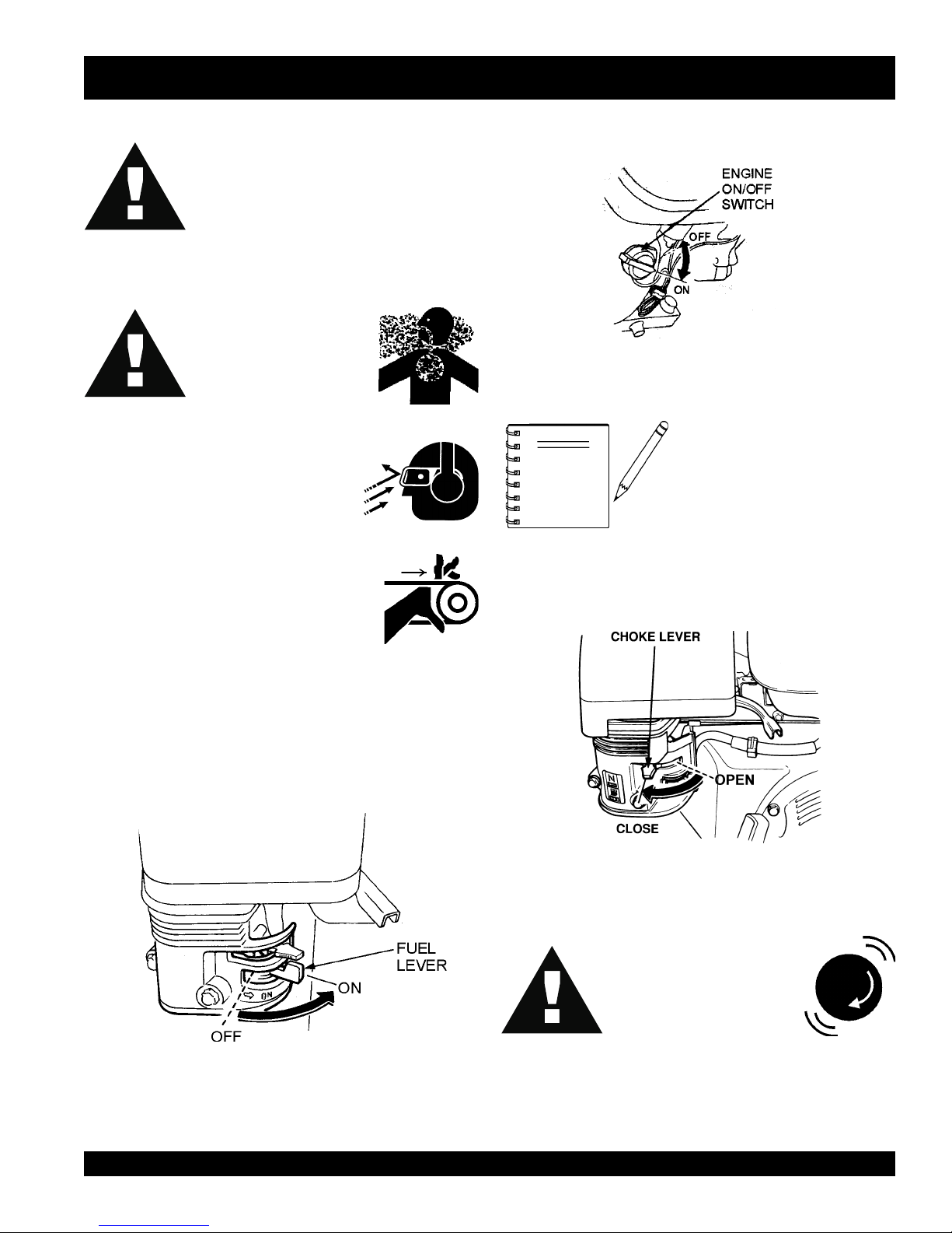
3. Place the
position.
NOTE
4. Place the
position.
Engine ON/OFF switch
Figure 18. Engine ON/OFF Switch
Choke Lever
(Figure 18) in the "ON"
The CLOSED position of the
choke lever enriches the fuel
mixture for starting a COLD engine.
The OPEN position provides the
correct fuel mixture for normal
operation after starting, and for
restarting a warm engine.
(Figure 19) in the "
CLOSED
"
1. Ensure the diamond blade has been mounted correctly and
that it is raised above the surface you are about to saw.
2. Place the
fuel valve lever
Figure 17. Engine Fuel Valve Lever
(Figure 17) to the "ON" position.
CAUTIONCAUTION
CAUTION
CAUTIONCAUTION
Figure 19. Choke Lever
The engine speed has
been set at the factory.
Changing the governor
speed could damage the
blade and/or the saw.
FCG1 CONCRETE SAW — OPERATION & PARTS MANUAL — REV. #1 (10/08/02) — PAGE 23
FCG1 CONCRETE SAW — OPERATION
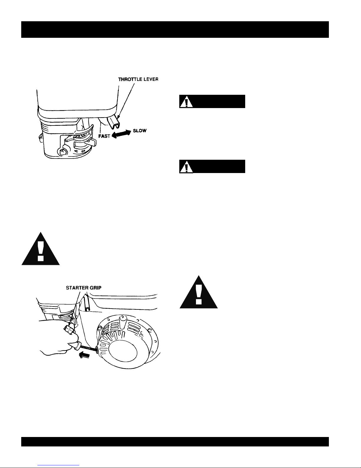
Rotate the
5.
and
engine governor speed is factory set to ensure optimum
blade operating speeds.
throttle lever
slow
for starting. All sawing is done at
(Figure 20) halfway between
full throttle
fast
. The
8.
Before the saw is placed into operation, run the engine for
several minutes. Check for fuel leaks, and noises that would
associate with a loose guards and/or covers.
9. Rotate the throttle lever (Figure 20) toward full throttle.
WARNING
ALWAYS cut with the saw at FULL THROTTLE. Attempting to
cut with the saw at less than full throttle could cause the blade to
bind or stop abruptly in the slab resulting in serious injury to the
operator or others in the area.
Figure 20. Throttle Lever
6. Grasp the starter grip (Figure 21) and slowly pull it out. The
resistance becomes the hardest at a certain position, corresponding to the compression point. Pull the starter grip briskly
and smoothly for starting.
CAUTIONCAUTION
CAUTION
CAUTIONCAUTION
DO NOT pull the starter rope all the way to
the end. DO NOT release the starter rope
after pulling. Allow it to rewind as soon as
possible.
WARNING
ALWAYS keep clear of
this equipment.
10. To begin sawing, lower the rotating blade allowing it to cut to
the preset depth.
11. When blade has reached full cutting depth, slowly walk
behind the saw at a rate that will allow the engine to operate
without losing optimum RPM.
CAUTIONCAUTION
CAUTION
CAUTIONCAUTION
12. When the end of the cut has been reached, raise the blade
out of the cut by pulling back on the handlebars (using a
downward pressure) until the raise/lower rod drops into its
slot with the blade in the raised position.
rotating
DO NOT try to cut faster than the blade will
allow. Cutting too fast will cause the blade to
rise up out of the cut. Improper cutting rate
can decrease the life of the engine and
blades.
or
moving
parts while operating
Figure 21. Starter Grip
7. If the engine has started, slowly return the choke lever
(Figure 19) to the
started repeat steps 1 through 5.
PAGE 24 — FCG1 CONCRETE SAW— OPERATION & PARTS MANUAL — REV. #1 (10/08/02)
"OPEN"
position. If the engine has not
13. If cutting is complete, turn the engine off and wait for the blade
to stop rotating.
 Loading...