

Page 1

OPERATION AND PARTS MANUAL
SERIES
MODEL EM120 HYDRAULIC
PLASTER/MORTAR MIXER
(HONDA GX390U1QA2 GASOLINE ENGINE)
Revision #1 (09/09/19)
To find the latest revision of this
publication, visit our website at:
www.multiquip.com
THIS MANUAL MUST ACCOMPANY THE EQUIPMENT AT ALL TIMES.
Page 2
PROPOSITION 65 WARNING
PAGE 2 — EM120 HYD. PLASTER/MORTAR MIXER • OPERATION AND PARTS MANUAL — REV. #1 (09/09/19)
Page 3
SILICOSIS/RESPIRATORY WARNINGS
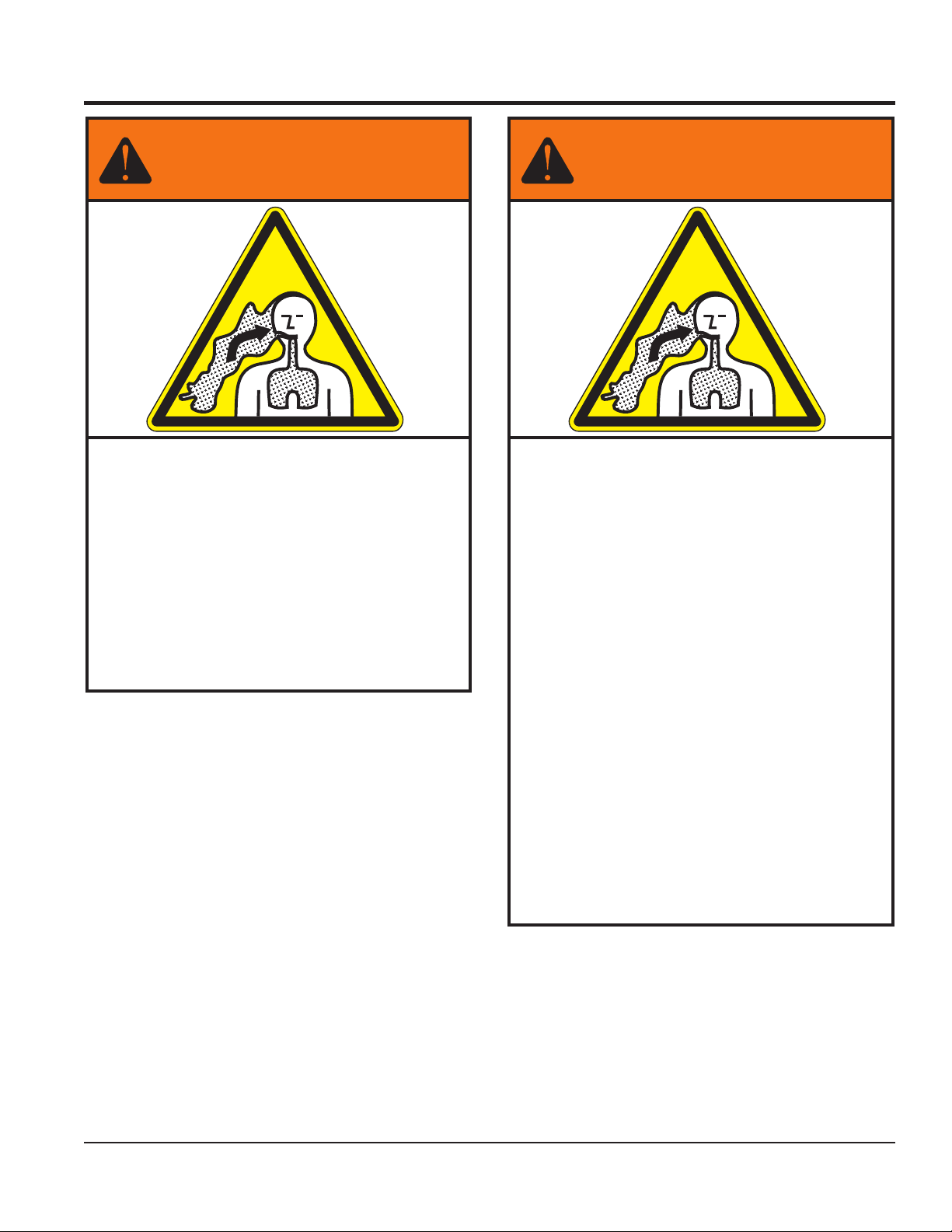
WARNING
SILICOSIS WARNING RESPIRATORY HAZARDS
Grinding/cutting/drilling of masonry, concrete, metal and
other materials with silica in their composition may give
off dust or mists containing crystalline silica. Silica is a
basic component of sand, quartz, brick clay, granite and
numerous other minerals and rocks. Repeated and/or
substantial inhalation of airborne crystalline silica can
cause serious or fatal respiratory diseases, including
silicosis.In addition, California and some other
authorities have listed respirable crystalline silica as a
substance known to cause cancer. When cutting such
materials, always follow the respiratory precautions
mentioned above.
WARNING
Grinding/cutting/drilling of masonry, concrete, metal and
other materials can generate dust, mists and fumes
containing chemicals known to cause serious or fatal
injury or illness, such as respiratory disease, cancer,
birth defects or other reproductive harm. If you are
unfamiliar with the risks associated with the particular
process and/or material being cut or the composition of
the tool being used, review the material safety data
sheet and/or consult your employer, the material
manufacturer/supplier, governmental agencies such as
OSHA and NIOSH and other sources on hazardous
materials. California and some other authorities, for
instance, have published lists of substances known to
cause cancer, reproductive toxicity,or other harmful
effects.
Control dust, mist and fumes at the source where
possible. In this regard use good work practices and
follow the recommendations of the manufacturers or
suppliers, OSHA/NIOSH, and occupational and trade
associations.Water should be used for dust
suppression when wet cutting is feasible. When the
hazards from inhalation of dust, mists and fumes cannot
be eliminated, the operator and any bystanders should
always wear a respirator approved by NIOSH/MSHA for
the materials being used.
EM120 HYD. PLASTER/MORTAR MIXER• OPERATION AND PARTS MANUAL — REV. #1 (09/09/19) — PAGE 3
Page 4

TABLE OF CONTENTS
EM120 Hydraulic
Plaster/Mortar Mixer
Proposition 65 Warning ........................................... 2
Silicosis/Respiratory Warnings ................................ 3
Table of Contents ..................................................... 4
Training Checklist .............................................. 5–11
Dimensions/Specifications ..................................... 12
Engine Specifications ............................................ 13
General Information ............................................... 14
Basic Components (Mixer) .................................... 15
Basic Components (Hydraulic) .............................. 16
Engine Components .............................................. 17
Towing Guidelines ................................................. 18
Safety Chain Connection ....................................... 19
Inspection ........................................................ 20–22
Start-Up ................................................................. 23
Start-Up/Operation ................................................ 24
Operation ............................................................... 25
Maintenance (Engine) ..................................... 26–28
Maintenance (Mixer) ........................................ 29–33
Hydraulic System Diagram .................................... 34
Troubleshooting (Mixer) ......................................... 35
Troubleshooting (Engine) ................................. 36–37
Explanation of Code in Remarks Column.............. 38
Suggested Spare Parts ......................................... 39
Component Drawings
Nameplate and Decals Assembly .................... 40–41
Paddle Blades Assembly ................................. 42–43
Drum and Shaft Assembly ............................... 44–45
Paddle Shaft Assembly .................................... 46–47
Hydraulic Assembly ......................................... 48–49
Frame Assembly .............................................. 50–51
Cabinet Assembly ............................................ 52–53
Engine Assembly ............................................. 54–55
Engine Service Parts ....................................... 56–57
NOTICE
Specifications and part numbers are subject to change
without notice.
PAGE 4 — EM120 HYD. PLASTER/MORTAR MIXER • OPERATION AND PARTS MANUAL — REV. #1 (09/09/19)
Page 5

TRAINING CHECKLIST
Training Checklist
No, Description OK? Date
1
2
3 Fuel system, refueling procedure.
4
5
6 Emergency stop procedures.
7 Machine transport and storage.
Read operation manual
completely.
Machine layout, location of
components, checking of engine
oil levels.
Operation of controls (machine
not running).
Safety controls, safety stop switch
operation.
EM120 HYD. PLASTER/MORTAR MIXER• OPERATION AND PARTS MANUAL — REV. #1 (09/09/19) — PAGE 5
Page 6
SAFETY INFORMATION
Do not operate or service the equipment before reading
the entire manual. Safety precautions should be followed
at all times when operating this equipment.
Failure to read and understand the safety
messages and operating instructions could
result in injury to yourself and others.
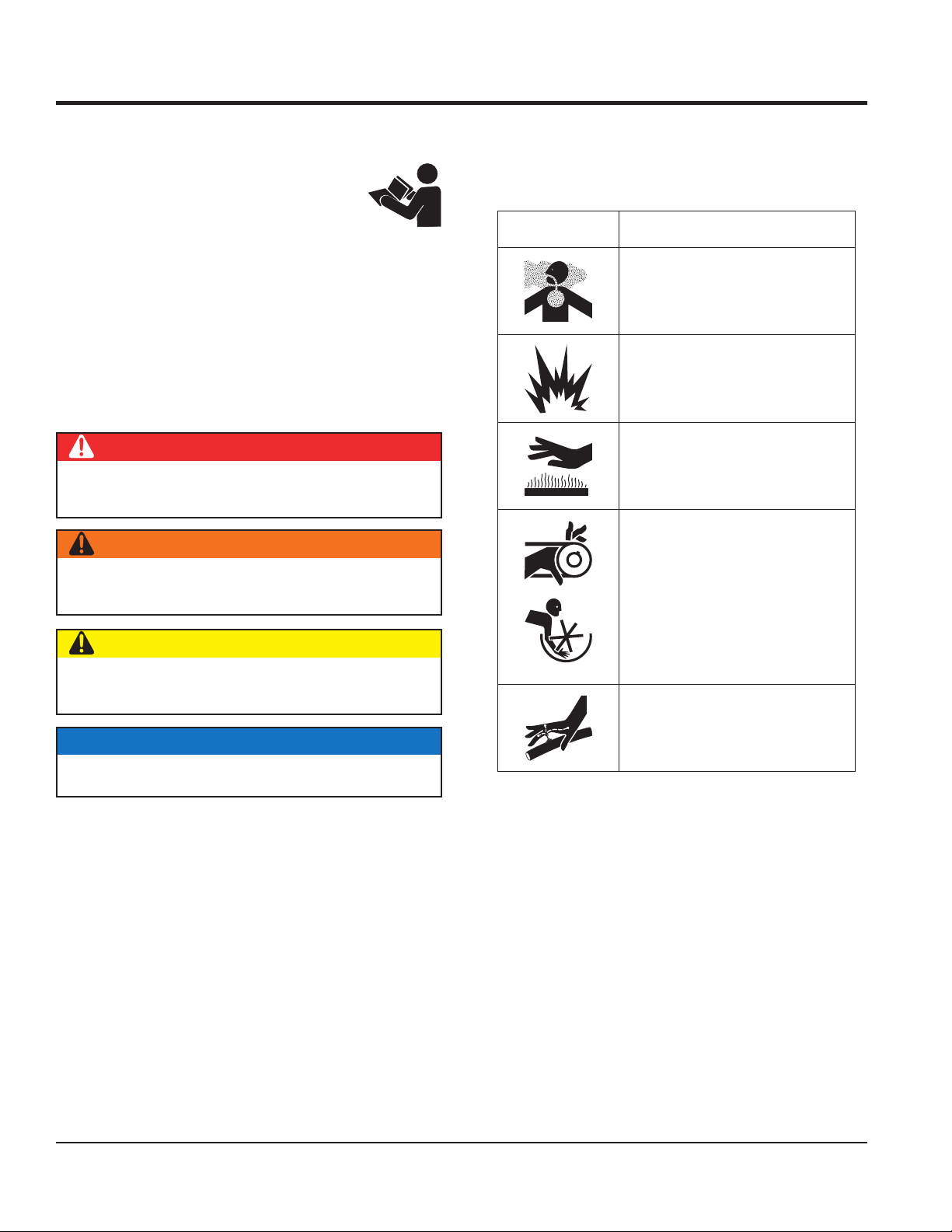
SAFETY MESSAGES
The four safety messages shown below will inform you
about potential hazards that could injure you or others. The
safety messages specifi cally address the level of exposure
to the operator and are preceded by one of four words:
DANGER, WARNING, CAUTION
SAFETY SYMBOLS
Potential hazards associated with the operation of this
equipment will be referenced with hazard symbols which
may appear throughout this manual in conjunction with
safety messages.
or NOTICE.
DANGER
Indicates a hazardous situation which, if not avoided,
WILL result in DEATH or SERIOUS INJURY.
WARNING
Indicates a hazardous situation which, if not avoided,
COULD result in DEATH or SERIOUS INJURY.
CAUTION
Indicates a hazardous situation which, if not avoided,
COULD result in MINOR or MODERATE INJURY.
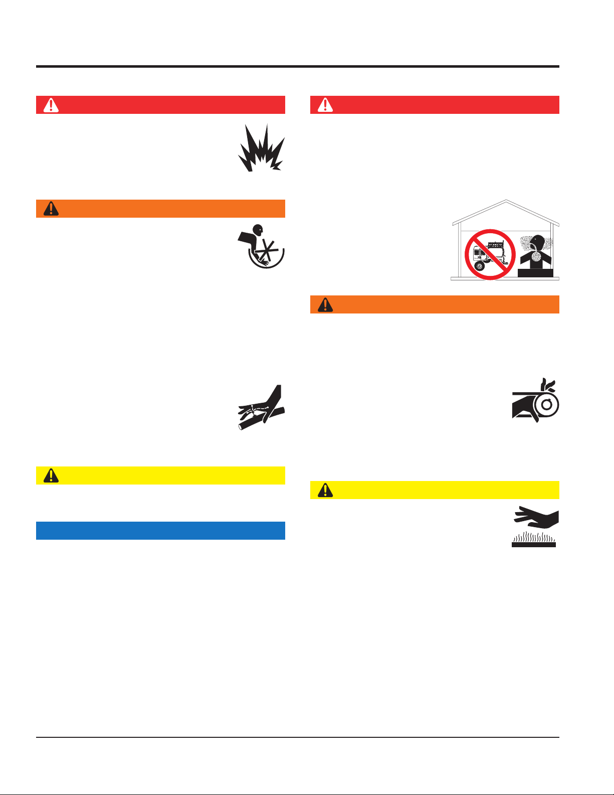
Symbol Safety Hazard
Lethal exhaust gas hazards
Explosive fuel hazards
Burn hazards
Rotating parts hazards
NOTICE
Hydraulic fluid hazards
Addresses practices not related to personal injury.
PAGE 6 — EM120 HYD. PLASTER/MORTAR MIXER • OPERATION AND PARTS MANUAL — REV. #1 (09/09/19)
Page 7
GENERAL SAFETY
NOTICE
This equipment should only be operated by trained and
Whenever necessary, replace nameplate, operation and
Manufacturer does not assume responsibility for any
accident due to equipment modifi cations. Unauthorized
use accessories or attachments that are not
recommended by Multiquip for this equipment. Damage
keep
Also, know the phone numbers
fi re department.
This information will be invaluable in the case of an
SAFETY INFORMATION
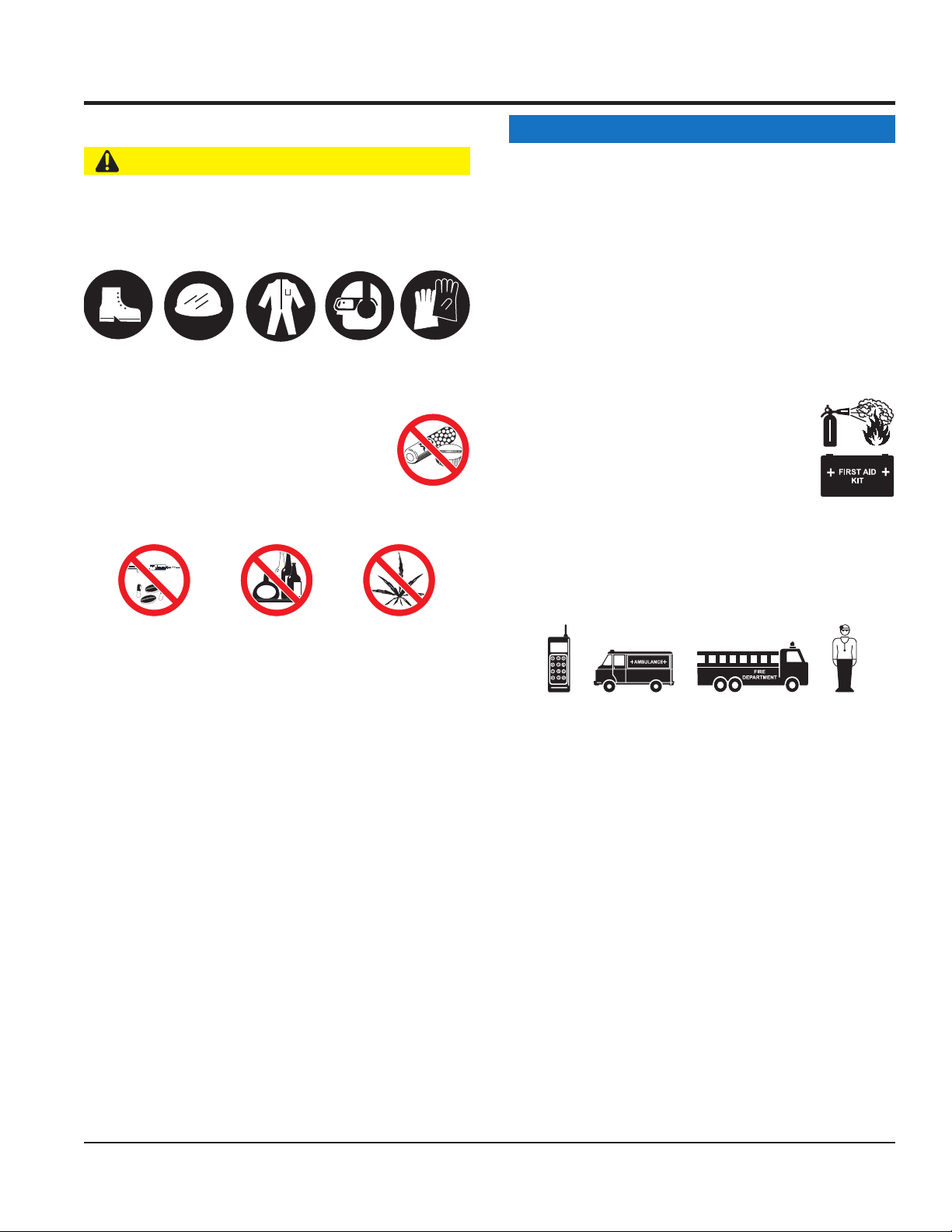
CAUTION
NEVER operate this equipment without proper protective
clothing, shatterproof glasses, respiratory protection,
hearing protection, steel-toed boots and other protective
devices required by the job or city and state regulations.
Avoid wearing jewelry or loose fi tting clothes that may
snag on the controls or moving parts as this can cause
serious injury.
NEVER operate this equipment when not
feeling well due to fatigue, illness or when
under medication.
NEVER operate this equipment under the
infl uence of drugs or alcohol.
ALWAYS clear the work area of any debris, tools, etc.
that would constitute a hazard while the equipment is
in operation.
ALWAYS check the equipment for loosened threads or
bolts before starting.
DO NOT use the equipment for any purpose other than
its intended purposes or applications.
qualifi ed personnel 18 years of age and older.
safety decals when they become diffi cult read.
equipment modifi cation will void all warranties.
NEVER
to the equipment and/or injury to user may result.
ALWAYS know the location of the nearest
fi re extinguisher.
ALWAYS know the location of the nearest
fi rst aid kit.
ALWAYS know the location of the nearest phone or
a phone on the job site.
of the nearest ambulance, doctor and
emergency.
EM120 HYD. PLASTER/MORTAR MIXER• OPERATION AND PARTS MANUAL — REV. #1 (09/09/19) — PAGE 7
Page 8
SAFETY INFORMATION
MIXER SAFETY
out of the reach of children and unauthorized personnel.
ENGINE SAFETY (GASOLINE MODELS ONLY)
Engine fuel exhaust gases contain poisonous carbon
monoxide. This gas is colorless and odorless, and can
The engine of this equipment requires an adequate
operate this equipment
place hands or fingers inside engine
operate the engine with heat shields or
while the engine is hot. Hot oil will gush out of the oil
tank and severely scald any persons in the general area
Make certain the operator knows how to and is capable
DANGER
NEVER operate the equipment in an explosive
atmosphere or near combustible materials. An
explosion or fi re could result causing severe
bodily harm or even death.
DO NOT mix fl ammable or explosive substances.
WARNING
NEVER place your hands inside the drum
while starting or operating this equipment.
NEVER disconnect any emergency
or safety devices. These devices are
intended for operator safety. Disconnection of these
devices can cause severe injury, bodily harm or even
death. Disconnection of any of these devices will void
all warranties.
Before operating mixer, ensure that safety grate is in
position and correctly fi tted.
NEVER use your hand to fi nd hydraulic
leaks. Use a piece of wood or cardboard.
Hydraulic fl uid injected into the skin must
be treated by a knowledgeable physician
immediately or severe injury or death can
occur.
CAUTION
NEVER lubricate components or attempt service on a
running machine.
NOTICE
ALWAYS keep the machine in proper running condition.
ALWAYS ensure mixer is on level ground before mixing.
DANGER
cause death if inhaled.
free fl ow of cooling air. NEVER
in any enclosed or narrow
area where free fl ow of the
air is restricted. If the air
fl ow is restricted it will cause
injury to people and property
and serious damage to the
equipment or engine.
WARNING
DO NOT
compartment when engine is running.
NEVER
guards removed.
Keep fi ngers, hands hair and clothing away
from all moving parts to prevent injury.
DO NOT remove the engine oil drain plug
of the mixer.
CAUTION
NEVER touch the hot exhaust manifold,
muffl er or cylinder. Allow these parts to cool
before servicing equipment.
of turning the engine OFF in case of an emergency.
DANGEROUS
GAS FUMES
Fix damage to machine and replace any broken parts
immediately.
DO NOT tip mixer onto drum mouth when the drum is
rotating.
Ensure the drum is rotating while fi lling and emptying
the drum.
ALWAYS store equipment properly when it is not being
used. Equipment should be stored in a clean, dry location
PAGE 8 — EM120 HYD. PLASTER/MORTAR MIXER • OPERATION AND PARTS MANUAL — REV. #1 (09/09/19)
Page 9
NOTICE
FUEL SAFETY (GASOLINE MODELS ONLY)
GENERATOR SAFETY
Operate electric motor only at the specifi ed voltage
disconnect AC power plug from power source
cables or cords when
connecting equipment to generator. Inspect for cuts in
Make sure power cables are securely connected.
Incorrect connections may cause electrical shock and
NEVER run engine without an air fi lter or with a dirty air
fi lter. Severe engine damage may occur. Service air fi lter
frequently to prevent engine malfunction.
NEVER tamper with the factory settings
of the engine or engine governor. Damage
to the engine or equipment can result
if operating in speed ranges above the
maximum allowable.
DANGER
DO NOT start the engine near spilled fuel or combustible
fl uids. Fuel is extremely fl ammable and its vapors can
cause an explosion if ignited.
SAFETY INFORMATION
(ELECTRIC MODELS ONLY)
If using a generator to power mixer, refer
to applicable generator manual safety
information section.
ELECTRIC MOTOR SAFETY
(ELECTRIC MODELS ONLY)
NOTICE
indicated on the nameplate.
DO NOT spray water onto electric motor.
ALWAYS
before moving mixer.
ALWAYS refuel in a well-ventilated area, away from
sparks and open fl ames.
ALWAYS use extreme caution when working with
fl ammable liquids.
DO NOT fi ll the fuel tank while the engine is running
or hot.
DO NOT overfi ll tank, since spilled fuel could ignite if it
comes into contact with hot engine parts or sparks from
the ignition system.
Store fuel in appropriate containers, in well-ventilated
areas and away from sparks and fl ames.
NEVER use fuel as a cleaning agent.
DO NOT smoke around or near the
equipment. Fire or explosion could result
from fuel vapors or if fuel is spilled on a
hot engine.
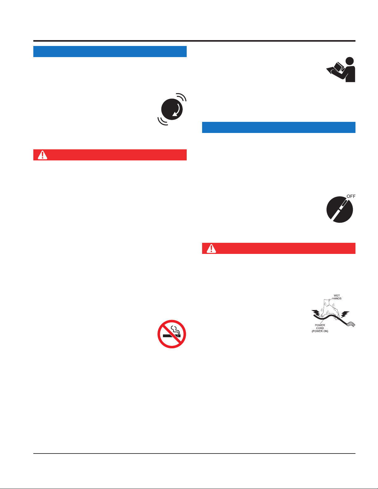
ALWAYS make sure the ON/OFF switch
on the electric motor is in the OFF position
when not in use and before inserting the
mixer’s power plug into an AC receptacle.
Power Cord/Cable Safety
DANGER
NEVER let power cords or cables lay in water.
NEVER use damaged or worn
the insulation.
NEVER grab or touch a live power
cord or cable with wet hands. The
possibility exists of electrical shock,
electrocution or death.
damage to the mixer.
EM120 HYD. PLASTER/MORTAR MIXER• OPERATION AND PARTS MANUAL — REV. #1 (09/09/19) — PAGE 9
Page 10

CAUTION
TRANSPORTING SAFETY
TOWING SAFETY
Check with your local county or state safety towing
Department of
Transportation (DOT) Safety Towing Regulations,
In order to reduce the possibility of an accident while
make
sure the towing vehicle is mechanically sound and in
NEVER
Check the tire air pressure on both towing vehicle and
Also
safety
attach mixer’s safety chains to towing
unless
posted otherwise. Recommended off-road towing is not to
Avoid sudden stops and starts. This can cause skidding,
or jack-knifi ng. Smooth, gradual starts and stops will
Mixer should be adjusted to a level position at all times
Raise and lock mixer wheel stand in up position when
rolling
SAFETY INFORMATION
Ensure that cables and cords will not be tripped over or
trapped underneath the mixer.
NOTICE
ALWAYS make certain that proper power or extension
cord has been selected for the job.
CAUTION
NEVER allow any person or animal to stand underneath
the equipment while lifting.
NOTICE
ALWAYS make sure forklift forks are inserted into pockets
(if applicable) as far as possible when lifting the mixer.
ALWAYS shutdown engine before transporting.
NEVER lift the equipment while the engine is running.
Tighten fuel tank cap securely and close fuel cock to
prevent fuel from spilling.
DO NOT lift machine to unnecessary heights.
ALWAYS tie down equipment during transport by
securing the equipment with rope.
NEVER tip the engine to extreme angles during lifting as
it may cause oil to gravitate into the cylinder head, making
the engine start diffi cult.
CAUTION
regulations, in addition to meeting
before towing your mixer.
transporting the mixer on public roads, ALWAYS
good operating condition.
ALWAYS shutdown engine before transporting.
ALWAYS inspect the hitch and coupling for wear.
tow a mixer with defective hitches, couplings, chains, etc.
mixer Mixer tires should be infl ated to 50 psi cold.
check the tire tread wear on the vehicle and mixer.
ALWAYS make sure the mixer is equipped with a
chain.
ALWAYS properly
vehicle.
The maximum speed for highway towing is 55 MPH
exceed 15 MPH or less depending on type of terrain.
improve towing.
Avoid sharp turns to prevent rolling.
PAGE 10 — EM120 HYD. PLASTER/MORTAR MIXER • OPERATION AND PARTS MANUAL — REV. #1 (09/09/19)
when towing.
towing.
Place chock blocks underneath wheel to prevent
while parked.
Page 11

SAFETY INFORMATION
ENVIRONMENTAL SAFETY/DECOMMISSIONING
Decommissioning is a controlled process used to safely
retire a piece of equipment that is no longer serviceable.
If the equipment poses an unacceptable and unrepairable
safety risk due to wear or damage or is no longer cost
effective to maintain (beyond life-cycle reliability) and is to
be decommissioned (demolition and dismantlement),be
sure to follow rules below.
EMISSIONS INFORMATION
The gasoline engine used in this equipment has been
designed to reduce harmful levels of carbon monoxide
(CO), hydrocarbons (HC) and nitrogen oxides (NOx)
This engine has been certifi ed to meet US EPA Evaporative
Attempting to modify or make adjustments to the engine
emmission system by unauthorized personnel without
proper training could damage the equipment or create an
Additionally, modifying the fuel system may adversely affect
evaporative emissions, resulting in fi nes or other penalties.
The emission control label is an integral part of the emission
If a replacement emission label is needed, please contact
NOTICE
DO NOT pour waste or oil directly onto the ground, down
a drain or into any water source.
Contact your country's Department of
Public Works or recycling agency in your
area and arrange for proper disposal of
any electrical components, waste or oil
associated with this equipment.
When the life cycle of this equipment is over, remove
battery if equipped and bring to appropriate facility for
lead reclamation. Use safety precautions when handling
batteries that contain sulfuric acid.
When the life cycle of this equipment is over, it is
recommended that the mixer frame and all other metal
parts be sent to a recycling center.
Metal recycling involves the collection of metal from
discarded products and its transformation into raw
materials to use in manufacturing a new product.
Recyclers and manufacturers alike promote the process
of recycling metal. Using a metal recycling center
promotes energy cost savings.
NOTICE
contained in gasoline exhaust emissions.
emissions requirements in the installed confi guration.
unsafe condition.
Emission Control Label
system and is strictly controlled by regulation(s).
The label must remain with the engine for its entire life.
your authorized engine distributor.
EM120 HYD. PLASTER/MORTAR MIXER• OPERATION AND PARTS MANUAL — REV. #1 (09/09/19) — PAGE 11
Page 12
HBC-1
2-INCH
BALL COUPLER
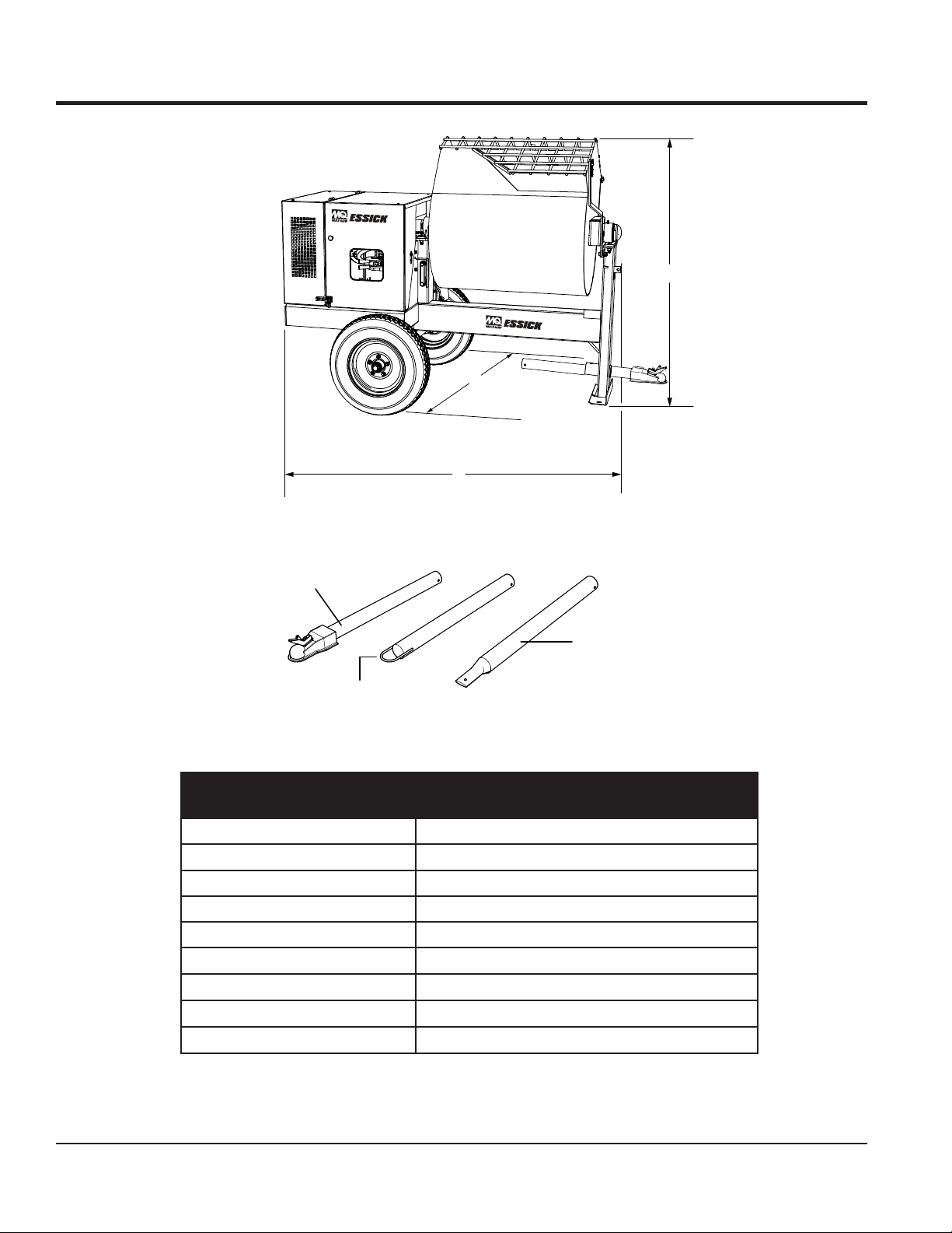
DIMENSIONS/SPECIFICATIONS
A
B
C
OPTIONAL TOW BARS
APPROXIMATE LENGTH
36IN. (914.4 MM)
HPC-1
1-INCH
PIN COUPLER
HLC-1
LOOP COUPLER
Figure 1. Dimensions
Table 1. EM120 Hyd.
Concrete Mixer Dimensions/Specifications
Reference Letter/Parameter Dimensions in. (mm)
A (Height) 62.5 (1,587)
B (Width) 56 1,422)
C (Length) 82 in. (2,083)
Maximum Mixing Capacity 12 cu. ft. (339.8 liters)
Bag Capacity
Hydraulic Oil Tank Capacity
Hydraulic Oil Type
Weight
Shell Tellius 68, Mobil DFE26 or Texaco Rand HDC
3.5 ~ 4 bags
12 gallons (45 liters)
1,010 lbs. (554 Kg)
PAGE 12 — EM120 HYD. PLASTER/MORTAR MIXER • OPERATION AND PARTS MANUAL — REV. #1 (09/09/19)
Page 13

ENGINE SPECIFICATIONS
Table 3. EM120 Hyd. Noise and Vibration
Guaranteed ISO 11201:2010 Based
Sound Pressure Level at Operator Station in dB(A)
Guaranteed ISO 3744:2010 Based
Sound Power Level in dB(A)
NOTES:
1. Sound Pressure and Power Levels are “A” weighted Measures per ISO 226:2003 (ANSI S1.4-1981). They are measured with the operating
condition of the machine which generates the most repeatable but highest values of the sound levels. Under normal circumstances, the sound
level will vary depending on the condition of the material being worked upon.
2. The vibration level indicated is the vector sum of the RMS (Root Mean Square) Values of amplitudes on each axis, standardized to an 8 hour
exposure period, and obtained using operating condition of the machine that generates the most repeatable but highest values in accordance
with the applicable standards for the machine.
Table 2. Engine Specifications/Dimensions
Model GX390U1QA2
Type
Bore X Stroke 3.2 in. X 2.5 in. (88 mm x 64 mm)
Displacement 389 cm
Max. Output 11.7 H.P. (8.7 kW) @ 3600 RPM
Continuous Rated Power
Max. Net Torque 26.5 Nm/2.70 kgfm/2,500 rpm
Ignition System Digital CDI with variable ignition timing
Fuel Tank Capacity 1.61 U.S. Gallons (Approx. 6.1 Liters)
Fuel Unleaded Gasoline
Lube Oil Capacity 1.06 qt. (1.1 liters)
Oil Type
Speed Control Method Centrifugal Flyweight Type
Cooling System Forced Air
Starting Method Recoil Start
Spark Plug Type BPR6ES NGK
Spark Plug Gap 0.028-0.031 in. (0.70 - 0.80 mm)
Dimension (L x W x H)
Dry Net Weight 69.9 lbs (31.7 Kg.)
Air cooled 4-stroke OHV petrol engine, 25° inclined
cylinder, horizontal shaft, cast iron sleeve
3
6.4 kW (8.6 HP)/3,000 rpm
7.0 kW (9.4 HP)/3,600 rpm
4-Stroke API, SF or SG
SAE 10W-30 General Use
16.0 x 18.1 X 17.6 in.
(406 X 460 X 448 mm)
TBD
TBD
EM120 HYD. PLASTER/MORTAR MIXER• OPERATION AND PARTS MANUAL — REV. #1 (09/09/19) — PAGE 13
Page 14

APPLICATION
This mixer is only intended for the mixing of plaster and
mortar. The mixer must be used for its intended purpose
and is not suitable for the mixing of flammable or explosive
substances. The mixer must not be used in an explosive
atmosphere.
The drum capacity of this hydraulic mixer is 12.0 cu. ft.
(340 liters) with a batch capacity between 3-1/2 and 4-1/2
bags. Mixer is shipped completely assembled and has been
factory tested and is ready for use.
POWER PLANTS
Mixer is powered by a 11.7 HP, air-cooled, 4-stroke gasoline
engine. Refer to Table 2 for specific engine details.
HARDWARE
Check all hardware on the mixer before starting. Periodically
inspect all hardware. Loose hardware can contribute
to early component failure and poor performance. Use
Table 4 as general guideline when the torqueing of mixer
hardware is required. Remember to keep all mixer hardware
components tight.
GENERAL INFORMATION
Table 4. Hardware Torque Recommendations
Hardware Diameter Torque (ft-lbs)
5/16-inch x 18 14
3/8-inch x 16 24
3/8-inch x 24 37
1/2-inch x 13 39
1/2-inch x 13 (Grade 8) 90
ENGINE MAINTENANCE
For basic engine maintenance, refer to the engine
maintenance section in this manual. For more detailed
engine maintenance, refer to the Honda Engine Owner's
manual furnished with the engine.
PAGE 14 — EM120 HYD. PLASTER/MORTAR MIXER • OPERATION AND PARTS MANUAL — REV. #1 (09/09/19)
Page 15
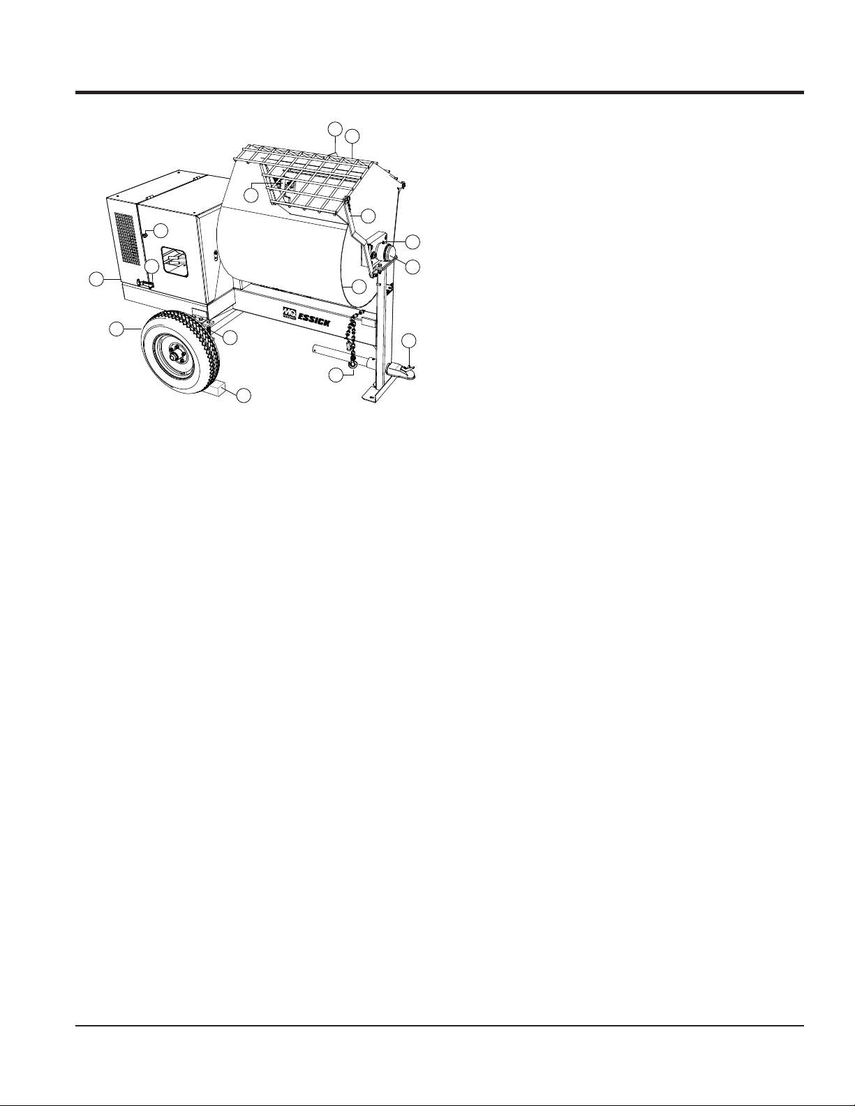
BASIC COMPONENTS (MIXER)
8. Safety Grill Lock Handle — To prevent injury to hands
6
7
5
8
3
2
4
11
9
10
and arms, the safety grill should ALWAYS be locked
when the mixing of plaster or mortar is required. Also
when transporting the mixer the safety grill should be
locked. The safety grill should only be un-locked when
cleaning of the blades and drum is required.
9. Pivot Point/Zerk Fitting — There is a zerk grease
fitting on each end of the mixing drum. These fittings
lubricate the dumping mechanism. Lubricate both
fittings at least twice a week.
1
Figure 2. Mixer Major Components
14
13
15
12
1. Tires Ply — The tire ply (layers) number is rated in
letters. This mixer uses 13-inch 2-ply tires. Replace
with only recommended type tires.
2. Engine Cover — Lift this cover to gain access to the
engine or electric motor.
3. ON/OFF Switch — This switch is located on the side
of the mixer frame. When activated it will shut down the
engine. Pull out when starting the engine.
4. Cabinet/Latch — Encloses engine and electric motor
(option). NEVER run mixer with cabinet removed. Use
latches to secure engine compartment cabinet.
5. Mixing Paddles — This mixer uses rubber mixing
paddles for the mixing of plaster and mortar. Always
clean paddles after each use
6. Bag Cutter — This feature allows mixing bags to be
opened easily, therefore allowing the contents of the
bag to fall directly into the mixing drum.
10. Drum Bearing — There is a sealed bearing on
each end of the mixing drum. Bearings are packed
and sealed at the factory and require no further
maintenance.
11. Mixing Drum — Steel mixing drum. Drum capacity is
12 cu. ft (340 liters). Mixing materials such as mortar,
plaster are to be placed into this drum for mixing.
Always clean the drum after each use. DO NOT use this
mixing drum for the mixing of volatile or hot liquids.
12. Tow Bar/Coupler — This mixer uses various towing
bars, please reference the frame assembly drawing
and parts list in this manual to determine which tow
bar meets your requirements.
13. Safety Chain — This mixer uses a 3/16-inch thick, 72
inches long zinc-plated saftey chain. ALWAYS connect
the safety chain when towing.
14. Cantilever (U-Type) Suspension — This mixer uses
a cantilever type suspension. Check the mounting
hardware for bolt hole elongation and tightness. See
maintenance section of this manual for recommended
maintenance.
15. Chock Blocks — Place these blocks (not included as
part of the mixer package) under each mixer wheel
to prevent rolling, when mixer is not connected to the
towing vehicle.
7. Safety Grill — Provided for operator safety. This safety
grill is designed to keep hands and solid objects out of
the mixing drum when in use. This grill should be closed
at all times when mixer is in use. DO NOT remove the
grill or grill opening bar. Keep the grill clean by washing
it down daily.
EM120 HYD. PLASTER/MORTAR MIXER• OPERATION AND PARTS MANUAL — REV. #1 (09/09/19) — PAGE 15
Page 16
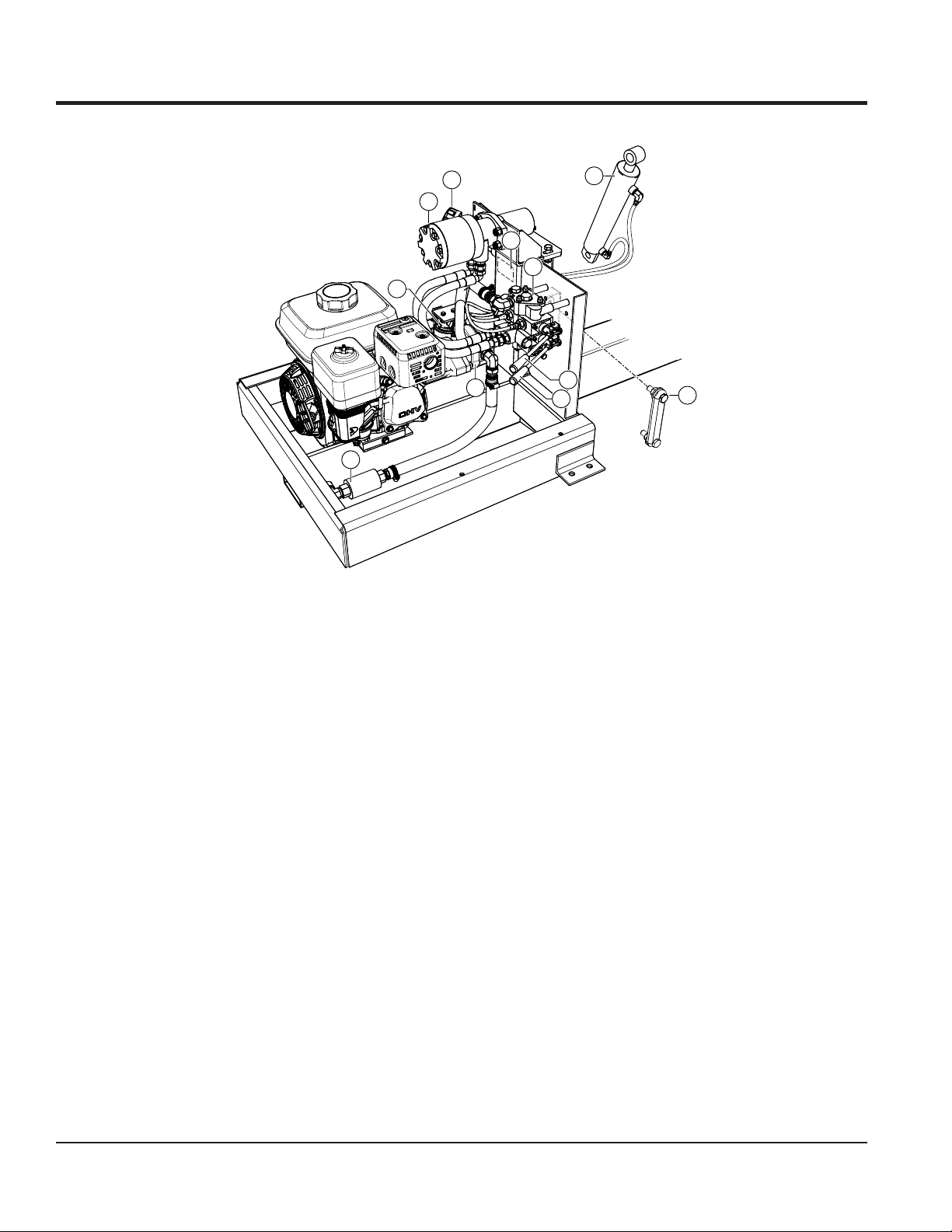
BASIC COMPONENTS (HYDRAULIC)
2
1
3
4
11
6
10
Figure 3. Hydraulic Components
7
8
5
9
Figure 3 illustrates the hydraulic components used on the
mixer.
1. Hydraulic Motor — Bi-directional hydraulic motor that
is used in conjunction with the directional control valve
to operate the hydraulic dump cylinder and paddle
shaft.
2. Hydraulic Oil Cap — Remove this cap to add hydraulic
oil to the hydraulic oil tank. Fill with hydraulic oil as
listed in Table 1. Make sure cap is tightened securely.
3. Hydraulic Oil Tank — This tank has a capacity of 12
gallons (45 liters). Fill with only recommended hydraulic
oil type as listed in Table 1.
4. Hydraulic Valve — Directional hydraulic control valve.
Controls the direction of hydraulic fluid supplied to the
dump cylinder and paddle shaft.
5. Hydraulic Dump Cylinder — When activated, this
cylinder will cause the mixing drum to rotate to the
dump position.
6. Hydraulic Pump — Supplies hydraulic fluid to the
hydraulic control valve.
7. Hydraulic Dump Lever — Pull lever outward to place
mixing drum in the dump position. Push lever inward
to return mixing drum to the upright position.
8. Hydraulic Paddle Blade Lever — 3-position lever.
Push inward for clockwise rotation of blades, pull
outward for counterclockwise rotation of blades. Place
in center position for no blade rotation (neutral).
9. Hydraulic Oil Sight Gauge — This gauge indicates
the level and temperature of the hydraulic oil. For
normal operation oil level should be visible at the 3/4
point on the sightglass.
10. Strainer — Filters out large particles and debris that
are harmful to the hydraulic system.
11. Hydraulic Oil Filter — 10 micron hydraulic filter. Filters
out small particles that are harmful to the hydraulic
system.
PAGE 16 — EM120 HYD. PLASTER/MORTAR MIXER • OPERATION AND PARTS MANUAL — REV. #1 (09/09/19)
Page 17
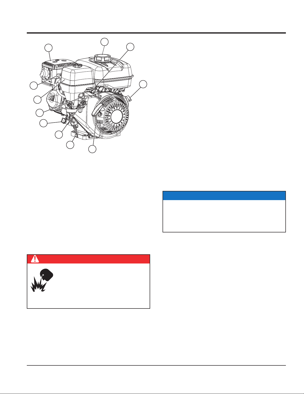
ENGINE COMPONENTS
1
11
10
2
3
9
8
7
6
5
Figure 4. Engine Components
4
INITIAL SERVICING
The engine (Figure 4) must be checked for proper
lubrication and filled with fuel prior to operation. Refer to the
manufacturer's engine manual for instructions and details
of operation and servicing.
1. Fuel Filler Cap/Fuel Tank – Remove this cap to add
unleaded gasoline to the fuel tank. Fill with unleaded
gasoline. Refer to Table 2 for fuel tank capacity. Make
sure cap is tightened securely. DO NOT over fill. For
additional information refer to Honda engine owner's
manual.
DANGER
Add fuel to the tank only when the engine
is stopped and has had an opportunity to
cool down. In the event of a fuel spill, DO
NOT attempt to start the engine until the
fuel residue has been completely wiped up
and the area surrounding the engine is dry.
2. Throttle Lever – Used to adjust engine RPM speed.
3. Engine On/Off Switch – ON position permits engine
starting, OFF position stops engine operation.
4. Recoil Starter (pull rope) – Manual-starting method.
Pull the starter grip until resistance is felt, then pull
briskly and smoothly.
5. Oil Drain Plug – Remove this plug to remove oil from
the engine's crankcase.
6. Fuel Valve Lever – OPEN to let fuel flow, CLOSE to
stop the flow of fuel.
7. Dipstick/Oil Filler Cap – Remove this cap to determine
if the engine oil is low. Add oil through this filler port as
recommended in Table 5.
8. Choke Lever – Used in the starting of a cold engine,
or in cold weather conditions. The choke enriches the
fuel mixture.
9. Air Cleaner – Prevents dirt and other debris from
entering the fuel system. Remove wing-nut on top of
air filter canister to gain access to filter element.
NOTICE
Operating the engine without an air filter, with a
damaged air filter, or a filter in need of replacement
will allow dirt to enter the engine, causing rapid engine
wear.
10. Spark Plug – Provides spark to the ignition system.
Set spark plug gap according to engine manufacturer's
instructions. Clean spark plug once a week.
11. Muffler – Used to reduce noise and emissions. NEVER
touch when hot!
EM120 HYD. PLASTER/MORTAR MIXER• OPERATION AND PARTS MANUAL — REV. #1 (09/09/19) — PAGE 17
Page 18

TOWING GUIDELINES
TOWING SAFETY PRECAUTIONS
CAUTION
Check with your county or state safety towing
regulations department before towing your
mixer.
To reduce the possibility of an accident while
transporting the mixer on public roads, always make
sure that the mixer towing components and the towing
vehicle are in good operating condition and both units
are mechanically sound.
The following list of suggestions should be used when
towing the mixer:
Make sure that the hitch and coupling of the towing
vehicle are rated equal to, or greater than the trailer
"gross vehicle weight rating" (GVWR).
ALWAYS inspect the hitch and coupling for wear. NEVER
tow the mixer with defective hitches, couplings, chains
etc.
ALWAYS make sure that the fuel valve lever is in the
OFF position (gasoline models only).
Check wheel mounting lug nuts with a torque wrench.
Torque wheel lug nuts as described in the maintenance
section of this manual.
Check tightness of U-clamp nuts, torque suspension
hardware as referenced in the maintenance section of
this manual.
Avoid sudden stops and starts. This can cause skidding,
or jackknifing. Smooth, gradual starts and stops will
improve gas milage.
Avoid sharp turns to prevent rolling.
CAUTION
If the mixer tow bar is deformed or damaged replace
entire tow bar. NEVER tow the mixer with a defective
tow bar. There exist the possibility of the trailer
separating from the towing vehicle.
CHECK the tire air pressure on both the towing vehicle
and the trailer. Also check the tire tread wear on both
vehicles.
ALWAYS make sure the mixer is equipped with a "Safety
Chain."
ALWAYS attach trailer's safety chain to the frame of
towing vehicle.
ALWAYS make sure that the towing vehicle's directional,
backup, and brake lights are working properly.
Remember in most cases the maximum speed unless
otherwise posted for highway towing is 55 MPH, however
before towing your mixer, check your local state, and
county vehicle towing requirements. Recommended offroad towing is not to exceed 15 MPH or less depending
on type of terrain.
Place chocked blocks underneath wheels to prevent
rolling
vehicle.
Inflate tires to correct pressure, inspect tires for cuts, and
excessive wear. See Table 7 (Tire Wear Troubleshooting).
When towing of the mixer is required, place the drum in
the up position (mouth facing upwards).
, while parked, if disconnected from towing
TOW BAR TO VEHICLE (COUPLER ONLY)
1. Check the vehicle hitch ball, and mixer's coupler for
signs of wear or damage. Replace any parts that are
worn or damaged before towing.
2. Use only a 2-inch ball diameter (towing vehicle), this will
match the mixer's 2-inch coupler. Use of any other ball
diameter will create an extremely dangerous condition
which can result in separation of the coupler and ball
or ball failure.
3. After tow bar has been connected to mixer (see next
page), attach mixer's coupler to the hitch ball on the
towing vehicle securely and make sure the lock lever
is in the down position (locked).
MIXER TOW BAR VEHICLE (PINTLE AND LOOP)
1. Make sure the bumper on the towing vehicle is
equipped to handle either a pintle or loop type tow
bar configuration.
2. After tow bar has been connected to mixer (see next
page), secure either type of tow bar to the towing
vehicle, following state and county towing regulations
3. As a minimum, use a 1/2-inch bolt and nylock nut grade
5 when securing either tow bar to the towing vehicle.
PAGE 18 — EM120 HYD. PLASTER/MORTAR MIXER • OPERATION AND PARTS MANUAL — REV. #1 (09/09/19)
Page 19

TOW BAR TO MIXER CONNECTION
Reference Figure A for the installation of the safety chain.
1.
Align the hole on the tow bar with the hole on the mixer
2. Route the safety chain through the holes just above
Extend the safety chain along the length of the tow bar,
looping it through the tow bar's connector link. Remove
Connect the free end of (connector link) the safety
chain to the towing vehicle. Remember it is critical
that the length of the chain be properly adjusted, to
prevent the draw bar and the front of the mixer stand
from dropping to the the ground (contact) in the event
the draw bar becomes disconnected from the towing
SAFETY CHAIN CONNECTION
CAUTION
NEVER tow the mixer with the safety chain removed.
The safety chain is intended to prevent complete
separation of the mixer from the towing vehicle in the
event of a tow bar failure.
Insert the tow bar through the round opening at the
bottom of the mixer stand.
frame, and insert 1/2-inch bolt through tow bar and
frame. Secure tow bar to frame with 1/2-inch nylock
nut. Tighten to 40 ft.-lbs.
the tow bar, located on each side of the mixer stand.
Loop the chain together and place under the tow bar.
Secure the loop with the connector link.
3.
any excess chain slack.
4.
vehicle.
CAUTION
DO NOT tow or lift the mixer unless the mixing drum
is completely empty.
Figure A. Tow Bar and Safety Chain Installation
CAUTION
Use a lifting device to lift tow bar onto vehicle coupler. If
lifting device is not available, have 2 persons of similar
height lift the tow bar. When lifting, do not attempt to lift
by bending forward. Bend hips and knees to squat down
to your load, keep it close to your body, and straighten
your legs to lift.
EM120 HYD. PLASTER/MORTAR MIXER• OPERATION AND PARTS MANUAL — REV. #1 (09/09/19) — PAGE 19
Page 20

Adjust paddles as shown in Figure 5.
CENTER TOW END
CAST PADDLE
ENGINE END
ADDLE
CAST P
INSPECTION
STEEL DRUM
ENGINE END
CAST PADDLE
DRUM END
CORRECT
CENTER ENGINE
END CAST PADDLE
INCORRECT
SIDE PADDLE BLADE
ROTATION
DRUM END AND SIDE WALLS
DRUM SIDE
INCORRECT
PADDLE BLADE IS TOO
TIGHT AGAINST DRUM
SIDE WALLS.
PADDLE BLADE IS TOO
TIGHT AGAINST DRUM
SIDE WALLS.
TOR TA OI N
P DNE EDALB ELDDA
CORRECT
Figure 5. Paddle Blade Adjustment
PAGE 20 — EM120 HYD. PLASTER/MORTAR MIXER • OPERATION AND PARTS MANUAL — REV. #1 (09/09/19)
Page 21

LOWER LIMIT
INSPECTION
BEFORE STARTING
1. Read all safety instructions at the beginning of manual.
2. Clean the unit, removing dirt and dust, particularly the
engine cooling air inlet, carburetor and air cleaner.
3. Check the air filter for dirt and dust. f air filter is dirty,
replace air filter with a new one as required.
4. Check carburetor for external dirt and dust. Clean with
dry compressed air.
5. Check fastening nuts and bolts for tightness.
CAUTION
ALWAYS wear approved eye and hearing
protection while operating the mixer.
CAUTION
NEVER place hands or feet inside the
engine guard cover while the engine is
running. ALWAYS shut the engine down
before performing any kind of maintenance
service on the mixer.
ENGINE OIL CHECK
1. To check the engine oil level, place the unit on secure
level ground with the engine stopped.
2. Remove the filler dipstick from the engine oil filler hole
(Figure 6) and wipe it clean.
5. I
NOTICE
Reference engine manufacturer’s manual for specific
servicing instructions.
UPPER LIMIT
Figure 7. Engine Oil Dipstick (Oil Level)
Table 5. Engine Oil Type
Season Temperature Oil Type
Summer 25°C or Higher SAE 10W-30
Spring/Fall 25°C ~ 10°C SAE 10W-30/20
Winter 0°C or Lower SAE 10W-10
FUEL CHECK
DANGER
If your mixer has a gasoline engine,
determine if the engine fuel is low. If fuel
is low, remove the fuel filler cap and fill it
with unleaded gasoline. Motor fuels are
highly flammable and can be dangerous
if mishandled. DO NOT smoke while refueling. DO
NOT attempt to refuel the mixer if the engine is hot!
or running.
CAUTION
NEVER! disable or disconnect the start/stop switch.
It is provided for operator safety. Injury may result if it
is disabled, disconnected or improperly maintained.
1. Remove the gasoline cap located on top of fuel tank.
Figure 6. Engine Oil Dipstick (Removal)
2. Visually inspect to see if fuel level is low. If fuel is low,
replenish with unleaded fuel.
3. Insert and remove the dipstick without screwing it into
the filler neck. Check the oil level shown on the dipstick.
3. When refueling, be sure to use a strainer for filtration.
DO NOT top-off fuel. Wipe up any spilled fuel
4. If the oil level is low (Figure 7), fill to the edge of the
immediately.
oil filler hole with the recommended oil type (Table 5).
Maximum oil capacity is 2.33 pints (1.09 liters).
EM120 HYD. PLASTER/MORTAR MIXER• OPERATION AND PARTS MANUAL — REV. #1 (09/09/19) — PAGE 21
Page 22

INSPECTION
HYDRAULIC OIL
Check hydraulic oil sight gauge (Figure 8) to ensure that
hydraulic oil is at the 3/4 level.
Figure 8. Hydraulic Oil Sight Gauge
HYDRAULIC HOSES
Check all hydraulic hoses to make sure they are not worn,
frayed or defective.
PADDLE BLADE CHECK
Check for worn or defective paddle blades (Figure 9).
Make sure that all blades are adjusted properly. See blade
adjustment procedure in this manual. Replace all defective
or damaged blades immediately using the part numbers
referenced in the parts section of this manual.
WORN RUBBER
TIRES
Check for worn or defective tires (Figure 10). Replace any
defective or worn tires immediately.
MISSING
RUBBER
CUT
BALDNESS
CRACKS
DEFORMED
Figure 10. Tire Wear
START/STOP SWITCH
This unit has been equipped with a start/stop switch
(Figure 11), which should be tested every time the unit
is started.
CRACKS
MISSING
RUBBER
Figure 11. Start/Stop Pushbutton Switch
MISSING
RUBBER
Figure 9. Worn Mixing Blade
PAGE 22 — EM120 HYD. PLASTER/MORTAR MIXER • OPERATION AND PARTS MANUAL — REV. #1 (09/09/19)
Page 23

START-UP
This section is intended to assist the operator with the initial
start-up of the unit. It is extremely important that
this section be read carefully before attempting
to use the mixer in the field. DO NOT use your
mixer until this section is thoroughly understood.
WARNING
Failure to understand the operation of the mixer could
result in severe damage to the mixer or personal injury.
Reference Figure 2 and Figure 3 for the location of any
components referenced in this manual.
CAUTION
NEVER operate the mixer in a confined
area or enclosed area structure that does
not provide ample free flow of air.
The following steps outline the procedure for starting the
engine.
1. Move the fuel shut-off lever (Figure 12) to the ON
position.
3. Move the throttle lever (Figure 14) away from the slow
position, about 1/3 of the way toward the fast position.
Figure 14. Throttle Lever
4. Turn the engine switch (Figure 15) to the ON position.
Figure 12. Fuel Shut-Off Lever
2. To start a cold engine, move the choke lever (Figure
13) to the CLOSED position.
Figure 15. Engine On/Off Switch
5. Located at the rear of the mixer frame is the main
start/ stop button (Figure 16). Pull this button outward
to start the engine.
Figure 16. Engine Start/Stop Button
Figure 13. Choke Lever
EM120 HYD. PLASTER/MORTAR MIXER• OPERATION AND PARTS MANUAL — REV. #1 (09/09/19) — PAGE 23
Page 24

START-UP/OPERATION
6. Pull the starter grip (Figure 17) lightly until you feel
resistance, then pull briskly. Return the starter grip
gently.
Figure 17. Starter Grip
MIXING
1. On the hydraulic valve, push the drive control lever
(Figure 18) inward for clockwise mixing rotation of
blades. For counterclockwise rotation, pull the drive
control lever outward.
BAG CUTTER
Figure 18. Paddle Shaft Rotation Lever
2. The paddle shaft inside the drum should be rotating
at this time.
3. Add a small amount water to the mixing drum
(Figure 19).
4. Lift the mixing bag compound (Figure 19) onto the steel
safety grate over the bag cutter and let the contents
fall into the drum. Add more water if desired and mix
compound to desired consistency.
Figure 19. Filling Mixing Drum
DUMPING
CAUTION
NEVER stand in front or behind the
mixing drum while it is being placed in the
dump position. Stay clear of the mixing
drum while it is being positioned.
1. Pull hydraulic dump lever (Figure 20) outward to place
drum in dump position (Figure 21).
When Dumping stand clear of tub
Figure 20. Dump Control Lever
PAGE 24 — EM120 HYD. PLASTER/MORTAR MIXER • OPERATION AND PARTS MANUAL — REV. #1 (09/09/19)
Page 25

OPERATION
WARNING
When rotating the
mixing drum from the
dump position to the
upright position, keep
hands clear of safety
grate. The possibility
exists of hands or
fingers being crushed.
STOPPING THE MIXER
1. Push the main start/stop switch (Figure 22) inward to
stop the engine.
Figure 22. Start/Stop Button (Stop Position)
2. Place fuel shut-off lever in the OFF position.
3. Clean drum of all debris and foreign matter.
Figure 21. Drum (Dump Position)
2. Push hydraulic dump lever inward to place drum back
in the upright position.
EM120 HYD. PLASTER/MORTAR MIXER• OPERATION AND PARTS MANUAL — REV. #1 (09/09/19) — PAGE 25
Page 26

MAINTENANCE (ENGINE)
Use Table 6 as a general maintenance guideline when servicing your engine. For more detail engine maintenance information,
refer to the engine owner’s manual supplied with your engine.
Table 6. Engine Maintenance Schedule
DESCRIPTION
(3)
Engine Oil
Air Cleaner
All Nuts and
Bolts
Spark Plugs
Cooling Fins Check X
Spark Arrester Clean X
Fuel Tank Clean X
Fuel Filter Check X
Idle Speed
OPERATION BEFORE
Check X
Change X
Check X
Change X (1)
Re-tighten if
necessary
Check/Clean X
Replace X
Check/
Adjust
X
FIRST
MONTH OR
10 HRS.
EVERY 3
MONTHS
OR 25 HRS.
EVERY 6
MONTHS
OR 50 HRS.
EVERY
YEAR
OR 100
HRS.
X (2)
EVERY 2
YEARS OR
200 HRS.
Valve
Clearance
Fuel Lines Check Every 2 years (replace if necessary) (2)
(1) Service more frequently when used in DUSTY areas.
(2) These items should be serviced by your service dealer, unless you have the proper tools and are mechanically
proficient. Refer to the HONDA Shop Manual for service procedures.
(3) For commercial use, log hours of operation to determine proper maintenance intervals.
Check/
Adjust
X (2)
PAGE 26 — EM120 HYD. PLASTER/MORTAR MIXER • OPERATION AND PARTS MANUAL — REV. #1 (09/09/19)
Page 27

MAINTENANCE (ENGINE)
0.024-0.028 IN.
GAP
MAINTENANCE
Perform the scheduled maintenance procedures as defined
by Table 6 and below:
DAILY
Thoroughly remove dirt and oil from the engine and
control area. Clean or replace the air cleaner elements
as necessary. Check and retighten all fasteners as
necessary.
Wiring
Inspect the entire mixer for bad or worn electrical wiring
or connections. If any wiring or connections are exposed
(insulation missing) replace wiring immediately.
Piping and Hose Connection
Inspect all piping, oil hose, hydraulic hose and fuel hose
connections for wear and tightness. Tighten all hose clamps
and check for leaks. If any hose lines are defective replace
them immediately.
Fuel Strainer
1. Thoroughly clean the area around the fuel cap.
2. Remove the fuel cap from the fuel tank.
3. Next, remove, inspect and clean the fuel strainer
(Figure 23) with solvent.
Spark Plug
1. Remove and clean the spark plug (Figure 24), then
adjust the spark gap to 0.024 ~0.028 inch (0.6~0.7
mm). This unit has electronic ignition, which requires
no adjustments.
(0.6-0.7 MM.)
Figure 24. Spark Plug Gap
ENGINE OIL
2. Drain the engine oil when the oil is warm as shown in
Figure 25.
3. Remove the oil drain bolt and sealing washer and allow
the oil to drain into a suitable container.
4. Replace engine oil with recommended type oil as
listed in Table 5. For engine oil capacity, see Table 2
(Engine Specifications). DO NOT overfill.
5. Install drain bolt with sealing washer and tighten
securely.
OIL FILLER CAP
DIPSTICK
DRAIN
BOLT
Figure 25. Draining Engine Oil
Figure 23. Fuel Strainer
SEALING
WASHER
EM120 HYD. PLASTER/MORTAR MIXER• OPERATION AND PARTS MANUAL — REV. #1 (09/09/19) — PAGE 27
Page 28

MAINTENANCE (ENGINE)
ENGINE AIR CLEANER
1. Remove the air cleaner cover and foam filter element
as shown in Figure 26.
2. Tap the paper filter element (Figure 26) several times
on a hard surface to remove dirt, or blow compressed
air [not exceeding 30 psi (207 kPa, 2.1 kgf/cm2)]
through the filter element from the air cleaner case
side. NEVER brush off dirt. Brushing will force dirt
into the fibers. Replace the paper filter element if it is
excessively dirty.
3. Clean foam element in warm, soapy water or
nonflammable solvent. Rinse and dry thoroughly. Dip
the element in clean engine oil and completely squeeze
out the excess oil from the element before installing.
DANGER
DO NOT use gasoline as a cleaning solvent to avoid
creating the risk of fire or an explosion.
SPARK ARRESTER CLEANING
Clean the spark arrester every 6 months or 100 hours.
1. Remove the 4 mm screw (3) from the exhaust deflector
(Figure 27), then remove the deflector.
Figure 26. Engine Air Cleaner
Figure 27. Spark Arrester
2. Remove the 5 mm screw (4) from the muffler protector,
then remove the muffler protector.
3. Carefully remove carbon deposits from the spark
arrester screen (Figure 28) with a wire brush
Figure 28. Cleaning The Spark Arrester
4. If the spark arrester is damaged and has breaks or
holes, replace with a new one.
5. Reinstall the spark arrester and muffler protector in
reverse order of disassembly.
PAGE 28 — EM120 HYD. PLASTER/MORTAR MIXER • OPERATION AND PARTS MANUAL — REV. #1 (09/09/19)
Page 29

MAINTENANCE (MIXER)
DRUM HEAD SEALS
On each end of the mixing drum there is a drum head
containing self-adjusting graphite seals. These seals
consist of packing rings, split gland and spring activated
adjusters. A properly maintained seal prevents material
from working around the shaft, causing excessive wear.
The following is the suggested procedure of maintenance
for protection of the paddle shaft.
1. Keep drum head clean of material build up so the spring
adjusters are free to work.
2. As the seals naturally wear, material will seep from the
drum head. Tighten the adjusting nuts equally until a
slight pressure is felt (Figure 29). The seals are now
tight. This procedure should be done periodically as
the seals leak.
DRUM BEARING BRACKET LUBRICATION
There is 1 set of drum bearing brackets (Figure 31) that
will require lubrication. These brackets are intended to
make the drum rotate freely. Lubricate the grease fitting
for each drum bearing bracket every month or when the
drum becomes difficult to position using multi-purpose
grade grease.
DRUM
BEARING
BRACKET
GREASE FITTING
AAA
AND CAP
Figure 29. Drum Seal Adjusting Nuts
3. Once the pressure plate touches the drum, its time to
replace the graphite seals (Figure 30).
Figure 30. Replacing Drum Seals
Figure 31. Grease Fittings (Dumping Mechanism)
HYDRAULIC OIL FILTER
Replace hydraulic oil filter (Figure 32) every 500 hours.
Hydraulic tank capacity is 12 gallons (45 liters). Refill with
any of the following hydraulic oil types. Shell Tellius 68,
Mobil DFE26 or Texaco Rand HDC
Figure 32. Hydraulic Oil Filter
EM120 HYD. PLASTER/MORTAR MIXER• OPERATION AND PARTS MANUAL — REV. #1 (09/09/19) — PAGE 29
Page 30

HYDRAULIC DUMP CYLINDER
CYLINDER
Lubricate the grease fitting (Figure 33) on the dump cylinder
using multi-purpose grade grease every two weeks.
GREASE
FITTING
CAP
GREASE
FITTING
MAINTENANCE (MIXER)
Figure 34. Wheel Hub and Bearings
2. Fill the wheel hub (Figure 34) with grease to the inside
diameter of the outer races and also fill the hub grease
cap. Reassemble the hub and mount the wheel. Then
tighten the adjusting nut, at the same time turn the
wheel in both directions, until there is a slight bind to
be sure all the bearing surfaces are in contact.
DUMP
Figure 33. Dump Cylinder Grease Fitting
BALL SOCKET AND CLAMP FACE MAINTENANCE
1. If the towing vehicle is equipped with a ball socket,
smear socket periodically with multi-purpose grease.
This will keep the ball socket well lubricated.
2. Periodically oil pivot points and clamp face surfaces
of coupler with SAE 30 WT. motor oil.
3. When parking or storing your mixer. Keep the coupler
off the ground so dirt will not build up in the ball socket.
WHEEL BEARINGS
1. After every 3 months of operation, remove the hub
dust cap and inspect the wheel bearings (Figure 34).
Once a year, or when required, disassemble the wheel
hubs remove the old grease and repack the bearings
forcing grease between rollers, cone and cage with a
good grade of high speed wheel bearing grease (never
use grease heavier than 265 A.S.T.M. penetration
(“No. 2.”).
Then back-off the adjusting nut 1/6 to 1/4 turn or to the
nearest locking hole or sufficiently to allow the wheel
to rotate freely within limits of .001” to .010” end play.
Lock the nut at this position. Install the cotter pin and
dust cap, and tighten all hardware.
MIXER CLEANING
It is important that the drum interior is free of dried material.
Obstructions can cause the paddle blades to lock against
the drum.
1. Push the “Engine Stop” button inward to the OFF
position to the stop the engine.
2. Place the hydraulic paddle lever (Figure 18) in the
neutral position do disengage.
3. ALWAYS disconnect the spark plug wire (gasoline
engines) before cleaning the inside of the drum. If mixer
is equipped with an electric motor remove power cord
from AC power source. In addition make sure the
clutch engagement lever is disengaged.
4. Place “Do Not Operate” tag on mixer.
5. Make sure the rear section of safety grate is connected
to the mixing drum.
PAGE 30 — EM120 HYD. PLASTER/MORTAR MIXER • OPERATION AND PARTS MANUAL — REV. #1 (09/09/19)
Page 31

MAINTENANCE (MIXER)
Wear Pattern Cause Solution
Center
Wear
Over Infl ation
Adjust pressure to
particular load per
tire manufacturer
Edge
Wear
Under
Infl ation
Adjust pressure to
particular load per
tire manufacturer.
Side
Wear
Loss of
chamber or
overloading
Make sure load does
not exceed axle
rating. Align wheels.
Toe
Wear
Incorrect
toe-in
Align wheels.
Cupping
Out of
balance
Check bearing
adjustment and
balance tires.
Flat
Spots
Wheel lockup
and tire
skidding
Avoid sudden stops
when possible and
adjust brakes.
6. At the end of each day’s operation, place mixer drum in
an upright position and spray inside of tub immediately
with water to prevent lumps of dried mortar or plaster
from forming and contamination of future batches.
7. DO NOT allow a buildup of materials to form on the
blades or anywhere inside the drum.
8. Rotate mixer to dump position and remove debris.
9. Thoroughly clean the entire mixer, wheels, cabinet
and frame.
10. NEVER! pour or spray water over the engine or electric
motor (Figure 35).
Tires Wear/Inflation
Tire inflation pressure is the most important factor in tire
life. Pressure should be checked cold before operation.
DO NOT bleed air from tires when they are hot. Check
inflation pressure weekly during use to insure the maximum
tire life and tread wear.
WARNING
ALWAYS wear safety glasses when removing
or installing force fitted parts. Failure to
comply may result in serious injury.
Table 7 (Tire Wear Troubleshooting) will help pinpoint the
causes and solutions of tire wear problems.
Table 7. Tire Wear Troubleshooting
Figure 35. No Spraying of Water
11. When cleaning of the entire mixer is done, return mixing
drum to an upright position..
Tires/Wheels/Lug Nuts
Tires and wheels are a very important and critical
components of the trailer. When specifying or replacing
the trailer wheels it is important the wheels, tires, and axle
are properly matched.
WARNING
DO NOT attempt to repair or modify a wheel.
DO NOT install an inter-tube to correct a leak
through the rim. If the rim is cracked, the air
pressure in the inter-tube may cause pieces
of the rim to explode (break-off) with great force and can
cause serious eye or bodily injury.
EM120 HYD. PLASTER/MORTAR MIXER• OPERATION AND PARTS MANUAL — REV. #1 (09/09/19) — PAGE 31
Page 32

MAINTENANCE (MIXER)
TORQUE WRENCH
Suspension
The cantilever (U-Type) suspension springs and associated
components (Figure 36) should be visually inspected
monthly for signs of excessive wear, elongation of bolt
holes, and loosening of fasteners. Replace all damaged
parts (suspension) immediately. Torque locknut securing
U-clamp to spring leaf between 45 and 50 ft.-lbs.
CHECK FOR
TIGHTNESS
NOTICE
NEVER use an pneumatic air gun to tighten wheel
lug nuts.
3. After first road use, retorque all lug nuts in sequence.
Check all wheel lug nuts periodically.
1
4
2
4-LUG NUTS
1
4
2
5
3
3
1
3
6
4
2
6-LUG NUTS
1
6
3
8
5
4
2
5
7
AXLE
Figure 36. Suspenion Components
Lug Nut Torque Requirements
It is extremely important to apply and maintain proper
wheel mounting torque. Be sure to use only the fasteners
matched to the cone angle of the wheel. Proper procedure
for attachment of the wheels is as follows:
1. Start all wheel lug nuts by hand.
2. Torque all lug nuts in sequence. See Figure 37. DO NOT
torque the wheel lug nuts all the way down. Tighten each
lug nut in 3 separate passes as defined by Figure 37.
Table 8. Tire Torque Requirements
Wheel Size
12" 20-25 35-40 50-65
13" 20-25 35-40 50-65
14" 20-25 50-60 90-120
15" 20-25 50-60 90-120
16" 20-25 50-60 90-120
First Pass
FT-LBS
Second Pass
FT-LBS
Third Pass
FT-LBS
5-LUG NUTS
PNEUMATIC
AIR GUN
8-LUG NUTS
LUG NUTS
Figure 37. Wheel Lug Nuts Tightening Sequence
PAGE 32 — EM120 HYD. PLASTER/MORTAR MIXER • OPERATION AND PARTS MANUAL — REV. #1 (09/09/19)
Page 33

MIXER STORAGE
For storage of the mixer for over 30 days, the following is
recommended:
Drain the fuel tank completely, or add STA-BIL to the fuel.
Run the engine until the fuel is completely consumed.
Completely drain used oil from the engine crankcase
and fill with fresh clean oil, then follow the procedures
described in the engine manual for engine storage.
Clean the entire mixer and engine compartment.
Place the mixing drum in the down position (mouth facing
downward).
Cover the mixer and place it a clean dry area, that is
protected from harsh elements.
MAINTENANCE (MIXER)
EM120 HYD. PLASTER/MORTAR MIXER• OPERATION AND PARTS MANUAL — REV. #1 (09/09/19) — PAGE 33
Page 34

HYDRAULIC SYSTEM DIAGRAM
Figure 38. Hydraulic System Diagram
PAGE 34 — EM120 HYD. PLASTER/MORTAR MIXER • OPERATION AND PARTS MANUAL — REV. #1 (09/09/19)
Page 35

TROUBLESHOOTING (MIXER)
Troubleshooting (Mixer)
Symptom Possible Problem Solution
Material load too heavy, exceeding
mixer capability?
Object stuck inside mixing drum,
jamming paddle rotation?
Blades will not rotate.
Material leaking from drum ends. Worn or defective paddle shaft seals? Replace seals.
Drum diffi cult to discharge (tilt).
Improper engine speed? Check and adjust engine speed.
Incorrect relief valve pressure? Inspect for proper relief pressure.
Defective hydraulic motor or pump? Contact MQ Technical Services.
Slow hydraulic cylinder dumping? Defective cylinder seal.
Defective or worn drum support
brackets?
Blades adjusted too tight.
Reduce amount of material being
mixed.
Stop engine. Empty out drum
contents. Remove obstruction.
Apply grease to bracket or replace.
Adjust blades until they almost touch
side walls of drum.
EM120 HYD. PLASTER/MORTAR MIXER• OPERATION AND PARTS MANUAL — REV. #1 (09/09/19) — PAGE 35
Page 36

Symptom Possible Problem Solution
Diffi cult to start, fuel is available, but no spark at
spark plug.
Diffi cult to start, fuel is available, and spark is
present at the spark plug.
Diffi cult to start, fuel is available, spark is
present and compression is normal.
Diffi cult to start, fuel is available, spark is
present and compression is low.
No fuel present at carburetor.
Will not start, no power with key "ON". (if
applicable)
TROUBLESHOOTING
Troubleshooting (Engine)
Spark plug bridging? Check gap, insulation or replace spark plug.
Carbon deposit on spark plug? Clean or replace spark plug.
Short circuit due to defi cient spark plug
insulation?
Improper spark plug gap? Set to proper gap.
Spark plug is red? Check transistor ignition unit.
Spark plug is bluish white?
No spark present at tip of spark plug?
No oil? Add oil as required.
Oil pressure alarm lamp blinks upon starting? (if
applicable)
ON/OFF switch is shorted? Check switch wiring, replace switch.
Ignition coil defective? Replace ignition coil.
Improper spark gap, points dirty? Set correct spark gap and clean points.
Condenser insulation worn or short circuiting? Replace condenser.
Spark plug wire broken or short circuiting? Replace defective spark plug wiring.
Wrong fuel type?
Water or dust in fuel system? Flush fuel system.
Air cleaner dirty? Clean or replace air cleaner.
Choke open? Close choke.
Suction/exhaust valve stuck or protruded? Reseat valves.
Piston ring and/or cylinder worn? Replace piston rings and/or piston.
Cylinder head and/or spark plug not tightened
properly?
Head gasket and/or spark plug gasket damaged? Replace head and spark plug gaskets.
No fuel in fuel tank? Fill with correct type of fuel.
Fuel cock does not open properly?
Fuel fi lter/lines clogged? Replace fuel fi lter.
Fuel tank cap breather hole clogged? Clean or replace fuel tank cap.
Air in fuel line? Bleed fuel line.
ON/OFF device not in ON position? Place ON/OFF device in ON posotion.
Check spark plug insulation, replace if worn.
If insuffi cient compression, repair or replace
engine. If injected air leaking, correct leak. If
carburetor jets clogged, clean carburetor.
Check transistor ignition unit is broken, and
replace defective unit. Check if voltage cord is
cracked or broken and replace. Check if spark
plug is fouled. Replace if fouled.
Check automatic shutdown circuit, "oil sensor".
(if applicable)
Flush fuel system, replace with correct type of
fuel.
Torque cylinder head bolts and spark plug.
Apply lubricant to loosen fuel cock lever,
replace if necessary.
PAGE 36 — EM120 HYD. PLASTER/MORTAR MIXER • OPERATION AND PARTS MANUAL — REV. #1 (09/09/19)
Page 37

Symptom Possible Problem Solution
Weak in power, compression is proper and
does not misfi re.
Weak in power, compression is proper but
misfi res.
Engine overheats.
Rotational speed fl uctuates.
Recoil starter malfunctions. (if applicable)
Burns too much fuel.
Exhaust color is continuously "white".
Exhaust color is continuously "black".
TROUBLESHOOTING
Troubleshooting (Engine) - continued
Air cleaner dirty? Clean or replace air cleaner.
Improper level in carburetor? Check fl oat adjustment, rebuild carburetor.
Defective spark plug? Clean or replace spark plug.
Improper spark plug? Set to proper gap.
Water in fuel system?
Dirty spark plug? Clean or replace spark plug.
Ignition coil defective? Replace ignition coil.
Spark plug heat value incorrect? Replace with correct type of spark plug.
Wrong type of fuel? Replace with correct type of fuel.
Cooling fi ns dirty? Clean cooling fi ns.
Intake air restricted?
Oil level too low or too high? Adjust oil to proper level.
Governor adjusted incorrectly? Adjust governor.
Governor spring defective? Replace governor spring.
Fuel fl ow restricted? Check entire fuel system for leaks or clogs.
Recoil mechanism clogged with dust and dirt? Clean recoil assembly with soap and water.
Spiral spring loose? Replace spiral spring.
Over-accumulation of exhaust products?
Wrong spark plug?
Lubricating oil is wrong viscosity? Replace lubricating oil with correct viscosity.
Worn rings? Replace rings.
Air cleaner clogged? Clean or replace air cleaner.
Choke valve set to incorrect position? Adjust choke valve to correct position.
Carburetor defective, seal on carburetor
broken?
Poor carburetor adjustment, engine runs too
rich?
Flush fuel system and replace with correct
type of fuel.
Clear intake of dirt and debris. Replace air
cleaner elements as necessary.
Check and clean valves. Check muffl er and
replace if necessary.
Replace spark plug with manufacturer's
suggested type.
Replace carburetor or seal.
Adjust carburetor.
EM120 HYD. PLASTER/MORTAR MIXER• OPERATION AND PARTS MANUAL — REV. #1 (09/09/19) — PAGE 37
Page 38

EXPLANATION OF CODE IN REMARKS COLUMN
The following section explains the different symbols and
remarks used in the Parts section of this manual. Use the
help numbers found on the back page of the manual if there
are any questions.
SAMPLE
NO.
1
2%
2%
3
4
NO. Column
PA R T
QTY. Column
— Item quantity can be indicated by a
A/R (As Required) is generally used for hoses or other
A blank entry generally indicates that the item is not sold
separately. Other entries will be clarified in the “Remarks”
Some of the most common notes found in the “Remarks”
Column are listed below. Other additional notes needed
— All items on the parts list with the
same unique symbol will be included when this item is
— Used to list an effective serial
— Indicates that the part
is used only with the specific model number or model
number variant listed. It can also be used to show a
part is NOT used on a specific model or model number
— Indicates that the part can
be purchased at any hardware shop or made out of
available items. Examples include battery cables, shims,
— Indicates that an item cannot
be purchased as a separate item and is either part of an
assembly/kit that can be purchased, or is not available
Numbers Used
number, a blank entry, or A/R.
NOTICE
The contents and part numbers listed in the parts
section are subject to change without notice. Multiquip
does not guarantee the availability of the parts listed.
PARTS LIST
PA R T NO. PA R T NAME QTY. REMARKS
12345 BOLT ......................1 .....INCLUDES ITEMS W/%
WASHER, 1/4 IN. ...........NOT SOLD SEPARATELY
12347 WASHER, 3/8 IN. ...1 .....MQ-45T ONLY
12348 HOSE ..................A/R ...MAKE LOCALLY
12349 BEARING ..............1 .....S/N 2345B AND ABOVE
Unique Symbols — All items with same unique
symbol
(@, #, +, %, or >) in the number column belong to the
same assembly or kit, which is indicated by a note in the
“Remarks” column.
Duplicate Item Numbers — Duplicate numbers indicate
multiple part numbers, which are in effect for the same
general item, such as different size saw blade guards in
use or a part that has been updated on newer versions
of the same machine.
parts that are sold in bulk and cut to length.
Column.
REMARKS Column
to describe the item can also be shown.
Assembly/Kit
purchased.
Indicated by:
“INCLUDES ITEMS W/(unique symbol)”
Serial Number Break
number range where a particular part is used.
Indicated by:
“S/N XXXXX AND BELOW”
“S/N XXXX AND ABOVE”
“S/N XXXX TO S/N XXX”
Specific Model Number Use
NOTICE
When ordering a part that has more than one item
number listed, check the remarks column for help in
determining the proper part to order.
NO. Column
Numbers Used — Part numbers can be indicated by a
variant.
Indicated by:
“XXXXX ONLY”
“NOT USED ON XXXX”
“Make/Obtain Locally”
number, a blank entry, or TBD.
TBD (To Be Determined) is generally used to show a
part that has not been assigned a formal part number
at the time of publication.
A blank entry generally indicates that the item is not sold
separately or is not sold by Multiquip. Other entries will
be clarified in the “Remarks” Column.
PAGE 38 — EM120 HYD. PLASTER/MORTAR MIXER • OPERATION AND PARTS MANUAL — REV. #1 (09/09/19)
and certain washers and nuts.
“Not Sold Separately”
for sale through Multiquip.
Page 39

SUGGESTED SPARE PARTS
EM120 HYDRAULIC MIXER
1 to 3 units
Qty. P/N Description
6............491010 ..................LATCH KIT, CABINET
1............EM200293B .......... PADDLE ARM, TOW END
1............EM200294B .......... PADDLE ARM CTR. TOW END
1............EM200295B .......... PADDLE ARM CTR. ENG END
1............EM200296B .......... PADDLE ARM, ENGINE END
1............EM200212 ............ SIDE WIPER, RUBBER
1............EM200213 ............ END WIPER, RUBBER
1............EM203432 ............ SIDE SCRAPER BLADE
1............EM203433 ............ END SCRAPER BLADE
4............EM200297 ............ U-BOLT
3............EM200863 ............ BLADE KIT, RUBBER
36..........EM200301 ............ PACKING RING
3............8051 ......................FILTER, HYDRAULIC
HONDA GX390U1QA2 GASOLINE ENGINE
1 to 3 units
3............9807955876 ..........SPARK PLUG
1............17620Z4H020 ....... TANK CAP
3............17210ZE2822 ....... AIR CLEANER ELEMENT
2............17218ZE2821 ....... FILTER OUTER
1............28462ZE2W11 ......ROPE, RECOIL
NOTICE
Part numbers on this Suggested Spare Parts list may
supersede/replace the part numbers shown in the
following parts lists.
EM120 HYD. PLASTER/MORTAR MIXER• OPERATION AND PARTS MANUAL — REV. #1 (09/09/19) — PAGE 39
Page 40

13
NAMEPLATE AND DECALS ASSY.
12
10
WARNING
To avoid injury, you read and
MUST
understand operator’s manual before
using this machine.
Keep safety grate, guards and doors
in place. Shut off engine or electric
motor before inspection or maintenance.
Moving parts can cut and crush.
engine or electric motor
SHUT OFF
before placing hands in mixing drum.
This machine to be operated by qualified
personnel only.Ask for training as needed.
11
P/N 521229
7
P/N 13238
1
2
3
4
CAUTION
INSPECT BEFORE TOWING
TIGHTNESS OF WHEEL NUTS
TIRE PRESSURE
1. Use manufacturer’s recommended torque values
when tightening wheel lug nuts.
2. Use manufacturer’s recommended tire pressure
values when inflating tires. DO NOT exceed
recommended tire pressure.
P/N 521232
5
6
7
8
QUALITY
MANAGEMENT SYSTEM
CERTIFIED ON
ISO 9001:2008
518524
4
4
CAUTION
INSPECT BEFORE TOWING
TIGHTNESS OF WHEEL NUTS
TIRE PRESSURE
1. Use manufacturer’s recommended torque values
5
when tightening wheel lug nuts.
2. Use manufacturer’s recommended tire pressure
values when inflating tires. DO NOT exceed
recommended tire pressure.
P/N 521232
SAFETY
INSTRUCTIONS
1. Read owner’s manual
before operating.
2. Keep unauthorized and untrained
people away from machine during
operation.
3. Make sure all safety devices are in
place before this machine is started.
4. Make sure engine is turned off and
spark plug wire is disconnected before
cleaning the machine.
5. Keep hands and fingers away from
moving objects.
6. Do not operate machine in an enclosed
area, proper ventilation is required.
7. Never leave machine unattended when
operating.
8. Always stop engine and allow engine
to cool before adding fuel or oil.
WARNING
To avoid injury, you read and
MUST
understand operator’s manual before
using this machine.
Keep safety grate, guards and doors
in place. Shut off engine or electric
motor before inspection or maintenance.
Moving parts can cut and crush.
engine or electric motor
SHUT OFF
before placing hands in mixing drum.
This machine to be operated by qualified
personnel only.Ask for training as needed.
P/N 521229
9
520935
10
PAGE 40 — EM120 HYD. PLASTER/MORTAR MIXER • OPERATION AND PARTS MANUAL — REV. #1 (09/09/19)
Page 41

NAMEPLATE AND DECALS ASSY.
NO. PART NO. PART NAME QTY. REMARKS
1 521230 DECAL; WARNING, PREVENT ACCIDENTS 1
2 NAMEPLATE ......................................................1................CONTACT MQ PARTS DEPT.
3 491757 RIVET, ID PLATE 2
4 510883 DECAL; MQ ESSICK (LARGE) 3
5 521232 DECAL; CAUTION INSPECT BEFORE TOW 2
6 985 DECAL; PLASTIC HYDRAULIC OIL ONLY 1
7 510891 DECAL; MQ ESSICK (SMALL) 2
8 518524 DECAL; ISO 9001:2000 EXPORT 1
9 520935 DECAL; SAFETY INSTRUCTIONS 1
10 521229 DECAL; WARNING, BODILY INJURY 2
11 948630 DECAL; PUSH TO STOP 1
12 521228 DECAL; DANGER, NO SMOKING 2
13 13238 DECAL; DUMP/DRIVE CONTROLS 1
EM120 HYD. PLASTER/MORTAR MIXER• OPERATION AND PARTS MANUAL — REV. #1 (09/09/19) — PAGE 41
Page 42

PADDLE BLADES ASSY.
PAGE 42 — EM120 HYD. PLASTER/MORTAR MIXER • OPERATION AND PARTS MANUAL — REV. #1 (09/09/19)
Page 43

PADDLE BLADES ASSY.
NO. PART NO. PART NAME QTY. REMARKS
2 492584 NUT, LOCK 1/2" DIA. NC 8
3 EM200294B PADDLE ARM CENTER (TOW END) 1
5 EM200292 INSERT, PADDLE ARM .....................................8................REPLACES P/N 200292
6 EM200296B PADDLE ARM, ENGINE END 1
7 6109170 WASHER, FLAT 1/2" ..........................................8................REPLACES P/N 504322
8 EM200297 U-BOLT ..............................................................4................REPLACES P/N 200297
9 EM200295B PADDLE ARM CENTER (ENGINE END) 1
10$ 2105162 SCREW HHC ....................................................14...............REPLACES P/N 492367
11$ EM923023 WASHER, FLAT 5/16" .......................................28...............REPLACES P/N 49259
12$ EM200212 SIDE WIPER, RUBBER 4
13$ EM203432 SIDE SCRAPER BLADE 4
14$ 2105164 NUT HEX 5/16" DIA. NC ...................................14...............REPLACES P/N 492553
15$ EM923343 WASHER, LOCK 5/16" .....................................14...............REPLACES P/N 492623
16 EM200293B PADDLE ARM, TOW END 1
17 EM203433 END SCRAPER BLADE 2
18 EM200213 END WIPER, RUBBER 2
19 EM200863 KIT, RUBBER BLADES, SCRAPERS & HDW. ...1................INCLUDES ITEMS W/$
EM120 HYD. PLASTER/MORTAR MIXER• OPERATION AND PARTS MANUAL — REV. #1 (09/09/19) — PAGE 43
Page 44

DRUM AND SHAFT ASSY.
1
5
4
3
2
9
8
ENGINE
SIDE
TOW
SIDE
7
6
3
10
FRAME
PAGE 44 — EM120 HYD. PLASTER/MORTAR MIXER • OPERATION AND PARTS MANUAL — REV. #1 (09/09/19)
Page 45

DRUM AND SHAFT ASSY.
NO. PART NO. PART NAME QTY. REMARKS
1 521678 DRUM AND SHAFT ASSY. ................................1................INCLUDES ITEMS W/$
2$ 925191 PIN, COTTER 3/16" 1
3$ 6109170 WASHER, FLAT 1/2" DIA. ..................................3................REPLACES P/N 49260
4$ 13276 BAR, GRATE OPENING 1
5$ EM203449 DRUM GRILL 1
6$ EM924015 PIN, COTTER ....................................................2................REPLACES P/N 505070
7$ 492584 NUT, NYLOC 1/2" DIA NC 1
8$ 6109170 WASHER, FLAT 1/2" DIA. ..................................1................REPLACES P/N 492600
9$ EM963692 BOLT, 1/2"UNC X 1-1/2" ....................................1................REPLACES P/N 492394
10 521676 DRUM 12. CU. FT ..............................................1................DRUM ONLY
EM120 HYD. PLASTER/MORTAR MIXER• OPERATION AND PARTS MANUAL — REV. #1 (09/09/19) — PAGE 45
Page 46

PADDLE SHAFT ASSY.
6
7
10
3
10
8
20
17
ENGINE
SIDE
TOW
SIDE
17
15
19
18
6
5
7
10
8
11
12
13
16
14
B
16
14
21
15
11
12
13
FRAME
23
22
24
A
A
1
4
2
3
9
32
31
29
30
28
27
26
FRAME
32
31
B
25
PAGE 46 — EM120 HYD. PLASTER/MORTAR MIXER • OPERATION AND PARTS MANUAL — REV. #1 (09/09/19)
Page 47

PADDLE SHAFT ASSY.
NO. PART NO. PART NAME QTY. REMARKS
1 3249 CAP, DUST 1
2 521674 BRACKET, FRONT 1
3 EM703 SCREW, ALLEN 3/8" .........................................4................REPLACES P/N 492470
4 EM200018 COLLAR, PADDLE SHAFT 2
5 492396 BOLT 1/2" NC X 2" G5 4
6 491008 GREASE CAP FITTING 2
7 EM916019 FITTING GREASE .............................................2................REPLACES P/N 491705
8 EM902153 BEARING ...........................................................2................REPLACES P/N 902153
9 EM969012 NUT, NYLOC 3/8" ..............................................8................REPLACES P/N 505066
10 EM201648 DRUM HEAD WELDMENT 2
11 EM200287 ADJUSTING NUT ..............................................4................REPLACES P/N 200287
12 0401450160 WASHER, FLAT 5/8" ..........................................4................REPLACES P/N 492602
13 507844 SPRING COMPRESSOR 4
14 EM200288 PLATE, PACKING GLAND PRESSURE 2
16 EM200301 RING, SHAFT PACKING 12
15 EM200285 GLAND, PACKING, HALF 4
16 EM200303 FOLLOWER, PACKING RING 2
18 EM200286 BOLT, CARRAGE ...............................................4................REPLACES P/N 505065
19 17985-008 BOLT, CARRIAGE ..............................................8................REPLACES P/N 505064
20 521675 PADDLE SHAFT 1
21 521673 BRACKET, REAR 1
22 EM502727 KEY, SQUARE 5/16 X 1-3/8" 1
23 514235 COUPLING HYDRAULIC MOTOR 1
24 492468 SCREW SET 5/16" 2
25 511526 SCREW, HHCS 1" NC X 8 1
26 13286 SPACER, LOWER DUMP CYLINDER 1
27 511495 NUT, LOCK 1" NC 1
28 EM963610 CAP SCREW .....................................................1................REPLACES P/N 492375
29 520957 WASHER, 3/8" FLAT 1
30 0166 A WASHER LOCK 3/8" DIA. .................................1................REPLACES P/N 492624
31 492584 NUT, NYLOC 1/2" DIA. NC 4
32 EM621 WASHER, 1/2" SPECIAL ...................................4................REPLACES P/N 621
EM120 HYD. PLASTER/MORTAR MIXER• OPERATION AND PARTS MANUAL — REV. #1 (09/09/19) — PAGE 47
Page 48

53
HYDRAULIC ASSY.
COUPLER
22
26
35
36
32
10
21
10
8
11
3535
12
16
19
26
6
6
2
14
4
52
25
70
71
40
71
70
PAGE 48 — EM120 HYD. PLASTER/MORTAR MIXER • OPERATION AND PARTS MANUAL — REV. #1 (09/09/19)
Page 49

HYDRAULIC ASSY.
NO. PART NO. PART NAME QTY. REMARKS
2 0166 A WASHER LOCK 3/8" DIA. .................................4................REPLACES P/N 492624
4 503117 BOLT 3/8" NC X 3" G5 3
6 13198 HOSE, ASM, DUMP CYL, 36" 2
8 13212 GROMMET, 1-1/4" ID 1
10 492584 NUT, NYLOC 1/2" DIA. NC 8
11 804032 BRACKET 1
12 492395 BOLT, 1/2"NC X 1-3/4" G5 4
14 515251 SPACER 3
16 EM34585 DIRECTIONAL CONTROL VALVE 1
18 13196 HOSE, PUMP OUTPUT, 21" 1
19 511845 FITTING 2
20 13210 STRAINER, IN LINE 1
21 515219 FITTING, 90° 1
22 3327 CYLINDER, DUMP 1
24 EM25459 ELBOW 3/4"-90° 1
25 511847 FITTING 1
26 3369 FITTING 2
28 13219 FITTING, 90° 1
30 3220 FITTING, STR 12BARB X 3/4MP 2
32 13243 HOSE, MOTOR, 17", W/90° FITTING 1
33 510263 FITTING, 90° STRAIGHT ELBOW 1
34 13225 HANDLE, DRIVE/DUMP VALVE CONTROL 2
35 492356 BOLT 1/4" X 3/4" 2
36 2101402 WASHER, LOCK 1/4" DIA. ................................2................REPLACES P/N 492622
40 13380 HOSE, 3/4"ID X 18-1/2 1
42 492396 BOLT, 1/2"NC X 2" 4
44 16587 FITTING .............................................................2................REPLACES P/N 3314
46 3322 FITTING, 90° 1
48 34570 MOTOR, HYDRAULIC 1
50 506207 CLAMP, HOSE 4
52 18052 OIL, SIGHT GAUGE 1
53 511691 FITTING, STR 1
54 3353 CAP, FILLER/BREATHER 1
56 3365 FITTING, STR 3
58 3367 FITTING, 90° 2
61 511847 FITTING, STR 1
62 3462 HOSE, .75 ID, 16.5 LONG 1
64 8051 FILTER, HYDRAULIC OIL 1
66 506094 PLUG 1/2"NPT GALVANIZED 1
70 804371 CLAMP, 1-1/4" 2
71 DULT100078J NUT M6, NYLOC G8 2
90 3407 KNOB 2
92 13242 HOSE W/90° FITTING 1
EM120 HYD. PLASTER/MORTAR MIXER• OPERATION AND PARTS MANUAL — REV. #1 (09/09/19) — PAGE 49
Page 50

FRAME ASSY.
1
2
17
A
NOTES:
A
OPTIONAL TOW BARS
15
16
15
14
13
15
12
3
4
11
5
7
6
8
9
10
21
18
22
20
19
PAGE 50 — EM120 HYD. PLASTER/MORTAR MIXER • OPERATION AND PARTS MANUAL — REV. #1 (09/09/19)
Page 51

FRAME ASSY.
NO. PART NO. PART NAME QTY. REMARKS
1 13365 CHASSIS ASSY. 1
2 501078 CHAIN SET 1
3 EM963692 BOLT 1/2"UNC X 1-1/2" .....................................4................REPLACES P/N 492394
4 3018 SPRING, LEAF 2
5 507444 WASHER, FLAT 3/4" 2
6 492534 NUT, CASTLE 3/4" 2
7 EM924008 PIN, COTTER 1/8" X 1-1/2" ...............................2................REPLACES P/N 491688
8 516477 WHEEL/TIRE ASSY. 2
9 29194 LUG NUT 10
10 3469 DUST CAP 2
11 504708 WASHER, FLAT 3/4" 2
12 EM941277 HUB COMPLETE, 5 LUGS 2
13 511699 AXLE 1
14 3028 U-BOLT, AXLE 2
15 492584 NUT LOCK 1/2" DIA. 10
16 3076 SPRING, AXLE 2
17 3043 BOLT 1/2" X 6" G5 .............................................2................REPLACES P/N 510721
18 HBC-1 TWO BAR (BALL HITCH 2-IN.) .........................1................CONTACT SALES
19 HLC-1 TOW BAR (LOOP) .............................................1................CONTACT SALES
20 HPC-1 TOW BAR (1" PIN) .............................................1................CONTACT SALES
EM120 HYD. PLASTER/MORTAR MIXER• OPERATION AND PARTS MANUAL — REV. #1 (09/09/19) — PAGE 51
Page 52

CABINET ASSY.
1
2
3
9
8
10
7
11
4
5
7
6
PAGE 52 — EM120 HYD. PLASTER/MORTAR MIXER • OPERATION AND PARTS MANUAL — REV. #1 (09/09/19)
Page 53

CABINET ASSY.
NO. PART NO. PART NAME QTY. REMARKS
1 EM505186 CUSHION RUBBER...........................................4................REPLACES P/N 505186
2 EM491028 WRAP, CABLE TIE .............................................1................REPLACES P/N 491028
3 511713 WEATHER STRIPPING SMALL ACCESS 1
4 512881 RIVET ...............................................................10...............REPLACES P/N 503723
5 491010 LATCH KIT, CABINET 2
6 EM963610 BOLT 3/8" ...........................................................4................REPLACES P/N 492376
7 3019092 WASHER, FLAT 3/8" ..........................................8................REPLACES P/N 492598
8 0166A WASHER, LOCK 3/8" ........................................4................REPLACES P/N 492624
9 1456 NUT, HEX 3/8" ...................................................4................REPLACES P/N 492554
10 511580 CABINET, ENGINE STEEL 1
11 518691 WEATHER STRIPPING LARGE ACCESS 1
EM120 HYD. PLASTER/MORTAR MIXER• OPERATION AND PARTS MANUAL — REV. #1 (09/09/19) — PAGE 53
Page 54

ENGINE ASSY.
6
5
4
2
1
PART OF
CABINET ASSY.
3
15
14
13
7
8
9
10
11
12
10
11
14
16
PAGE 54 — EM120 HYD. PLASTER/MORTAR MIXER • OPERATION AND PARTS MANUAL — REV. #1 (09/09/19)
Page 55

ENGINE ASSY.
NO. PART NO. PART NAME QTY. REMARKS
1 29174-001 KNOB, MUSHROOM 1
2 29173-001 SWITCH, PUSH PULL W/OUT KNOB 1
3 510573 HARNESS CABLE, ENGINE 1
4 3364 ENGINE, HONDA 11.7HP, GX390U1QA2 1
5 203148 TUBE, EXHAUST 1
6 491757 RIVET 4
7 203123 FLANGE, EXHAUST PIPE 1
8 90745ZE2600 KEY, SQUARE 6.3X6.43X43 1
9 EM203040 ENGINE SHAFT SLEEVE 1
10 0166A WASHER, LOCK 3/8" DIA. ................................6................REPLACES P/N 492624
11 EM963610 BOLT 3/8" ...........................................................6................REPLACES P/N 492376
12 13374 PUMP, EATON 1
13 516282 COUPLING ASSY. 1
14 3019092 WASHER, FLAT 3/8" ..........................................6................REPLACES P/N 492598
15 492379 SCREW, CAP 3/8" 4
16 EM969013 NUT 3/8" NC NYLOC G8 ...................................4................REPLACES P/N 492583
EM120 HYD. PLASTER/MORTAR MIXER• OPERATION AND PARTS MANUAL — REV. #1 (09/09/19) — PAGE 55
Page 56

ENGINE SERVICE PARTS
PAGE 56 — EM120 HYD. PLASTER/MORTAR MIXER • OPERATION AND PARTS MANUAL — REV. #1 (09/09/19)
Page 57

ENGINE SERVICE PARTS
NO. PART NO. PART NAME QTY. REMARKS
1 17620Z0T305 TANK CAP, CHROME PLATED 1
2 17672ZE2W01 FUEL FILTER 1
3 28462ZE3W01 ROPE, RECOIL 1
4 17210ZE3010 AIR CLEANER ELEMENT 1
5 17218ZE3000 FILTER OUTER 1
6 9807955846 SPARK PLUG, BPR5ES (NGK) 1
EM120 HYD. PLASTER/MORTAR MIXER• OPERATION AND PARTS MANUAL — REV. #1 (09/09/19) — PAGE 57
Page 58

OPERATION AND PARTS MANUAL
HERE’S HOW TO GET HELP
© COPYRIGHT 2019, MULTIQUIP INC.
Multiquip Inc
the MQ logo are registered trademarks of Multiquip Inc. and may not be used, reproduced, or altered without written permission. All other trademarks are the property
of their respective owners and used with permission.
This manual
The information and specifi cations included in this publication were in effect at the time of approval for printing. Illustrations, descriptions, references and technical data contained in
this manual are for guidance only and may not be considered as binding. Multiquip Inc. reserves the right to discontinue or change specifi cations, design or the information published
in this publication at any time without notice and without incurring any obligations.
PLEASE HAVE THE MODEL AND SERIAL
NUMBER ON-HAND WHEN CALLING
UNITED STATES
Multiquip Inc.
(310) 537- 3700
6141 Katella Avenue Suite 200
Cypress, CA 90630
E-MAIL: mq@multiquip.com
WEBSITE: www.multiquip.com
CANADA
Multiquip Multiquip (UK) Limited Head Offi ce
(450) 625-2244
4110 Industriel Boul.
Laval, Quebec, Canada H7L 6V3
E-MAIL : infocanada@multiquip.com
UNITED KINGDOM
0161 339 2223
Unit 2, Northpoint Industrial Estate,
Globe Lane,
Dukinfi eld, Cheshire SK16 4UJ
E-MAIL : sales@multiquip.co.uk
,
MUST accompany the equipment at all times. This manual is considered a permanent part of the equipment and should remain with the unit if resold.
Your Local Dealer is:
 Loading...