

Page 1

OPERATION AND PARTS MANUAL
CV/SVA-SERIES
MODELS
900, 1000, 1300,
1400, 1700, 2100, 2600
VIBRATOR HEADS
Revision #0 (03/22/10)
To find the latest revision of this
publication, visit our website at:
www.multiquip.com
THIS MANUAL MUST ACCOMPANY THE EQUIPMENT AT ALL TIMES.
PN: 36858
Page 2
PROPOSITION 65 WARNING
Engine exhaust and some of
its constituents, and some dust created
by power sanding, sawing, grinding,
drillingandotherconstructionactivities
contains chemicals known to the State
of California to cause cancer, birth
defects and other reproductive harm.
Some examples of these chemicals are:
Leadfromlead-basedpaints.
Crystallinesilicafrombricks.
Cementandothermasonryproducts.
Arsenicandchromiumfrom chemically
treatedlumber.
Your risk from these exposures varies,
dependingonhowoftenyoudothistype
of work. To reduce your exposure to
these chemicals: work in aALWAYS
well ventilated area, and work with
approved safety equipment, such as
dust masks that are specially designed
to filter out microscopic particles.
PAGE 2 — CV/SVA-SERIES VIBRATOR HEADS — OPERATION AND PARTS MANUAL — REV. #0 (03/22/10)
Page 3
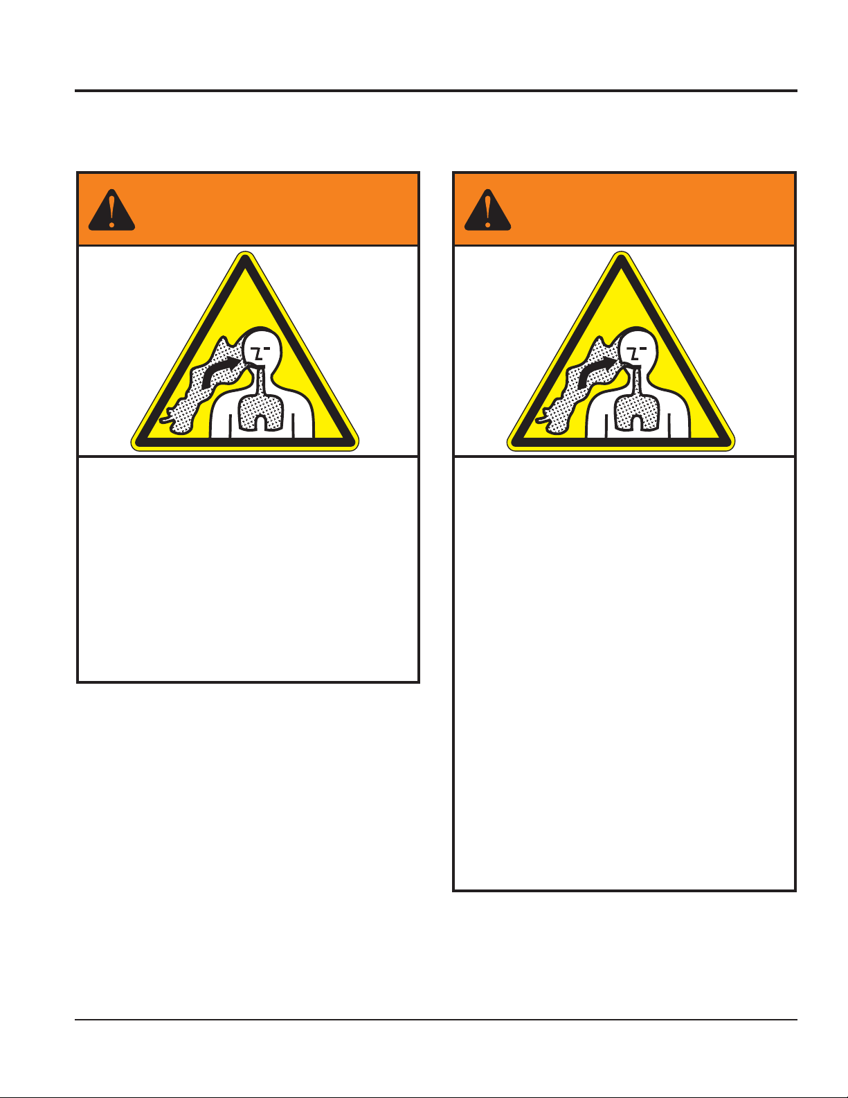
SILICOSIS/RESPIRATORY WARNINGS
WARNING
SILICOSIS WARNING RESPIRATORY HAZARDS
Grinding/cutting/drilling of masonry, concrete, metal and
other materials with silica in their composition may give
off dust or mists containing crystalline silica. Silica is a
basic component of sand, quartz, brick clay, granite and
numerous other minerals and rocks. Repeated and/or
substantial inhalation of airborne crystalline silica can
cause serious or fatal respiratory diseases, including
silicosis. In addition, California and some other
authorities have listed respirable crystalline silica as a
substance known to cause cancer. When cutting such
materials, always follow the respiratory precautions
mentioned above.
WARNING
Grinding/cutting/drilling of masonry, concrete, metal and
other materials can generate dust, mists and fumes
containing chemicals known to cause serious or fatal
injury or illness, such as respiratory disease, cancer,
birth defects or other reproductive harm. If you are
unfamiliar with the risks associated with the particular
process and/or material being cut or the composition of
the tool being used, review the material safety data
sheet and/or consult your employer, the material
manufacturer/supplier, governmental agencies such as
OSHA and NIOSH and other sources on hazardous
materials. California and some other authorities, for
instance, have published lists of substances known to
cause cancer, reproductive toxicity, or other harmful
effects.
Control dust, mist and fumes at the source where
possible. In this regard use good work practices and
follow the recommendations of the manufacturers or
suppliers, OSHA/NIOSH, and occupational and trade
associations. Water should be used for dust
suppression when wet cutting is feasible. When the
hazards from inhalation of dust, mists and fumes cannot
be eliminated, the operator and any bystanders should
always wear a respirator approved by NIOSH/MSHA for
the materials being used.
CV/SVA-SERIES VIBRATOR HEADS — OPERATION AND PARTS MANUAL — REV. #0 (03/22/10) — PAGE 3
Page 4

CV/SVA-Series Vibrator Heads
Proposition 65 Warning ........................................... 2
Silicosis/Respiratory Warnings ................................ 3
Table Of Contents ................................................... 4
Parts Ordering Procedures ..................................... 5
Safety Message Alert Symbols ............................... 6
Rules For Safe Operation ....................................... 7
Preparation and Operation ..................................... 8
Maintenance ...................................................... 9-10
Specifications ........................................................ 11
Seal Installation ..................................................... 12
Vibrator Head Assy. .......................................... 14-17
Terms And Conditions Of Sale .............................. 18
TABLE OF CONTENTS
Specifications and part numbers are subject
to change without notice.
PAGE 4 — CV/SVA-SERIES VIBRATOR HEADS — OPERATION AND PARTS MANUAL — REV. #0 (03/22/10)
Page 5
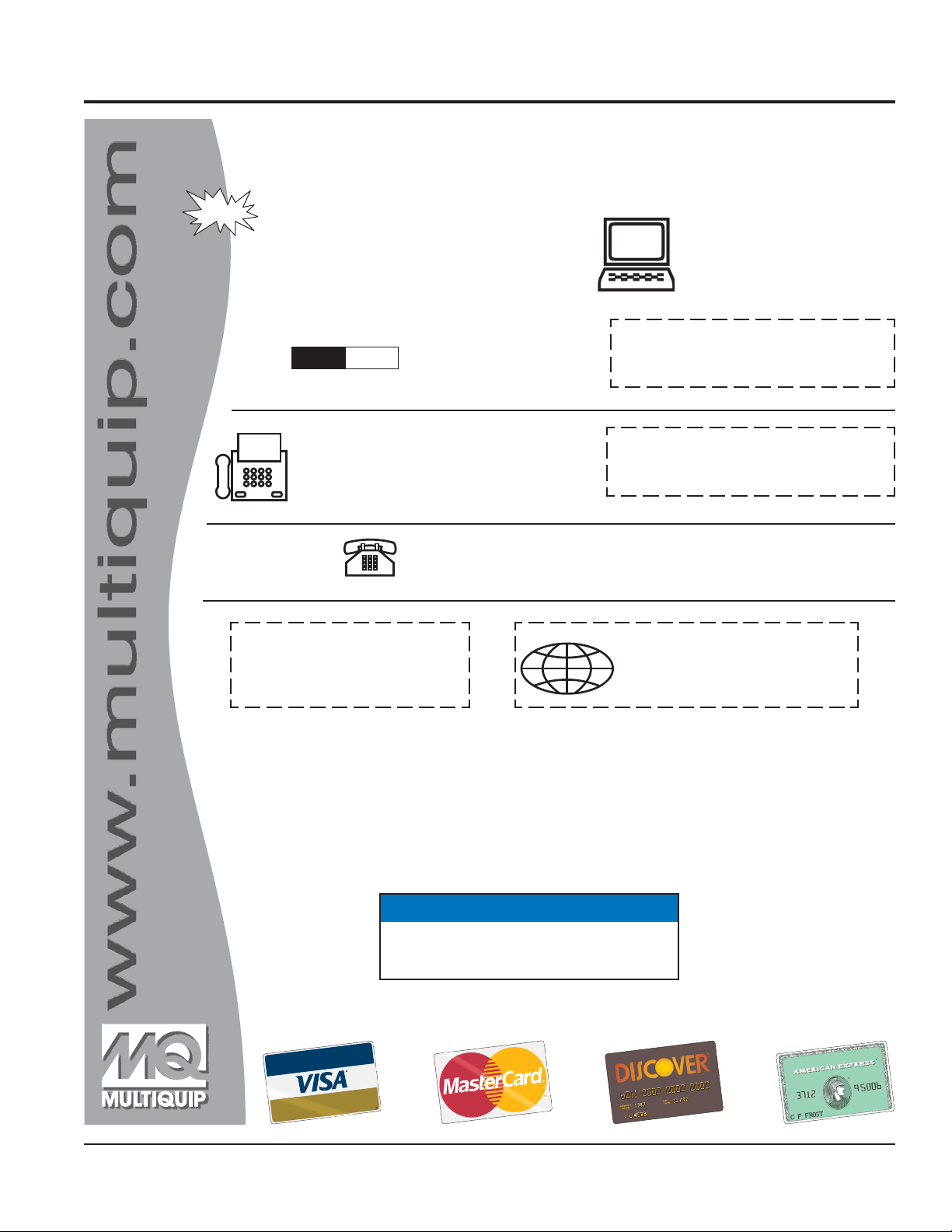
PARTS ORDERING PROCEDURES
Ordering parts has never been easier!
Choose from three easy options:
January 1
Effective:
st
, 2006
Best Deal!
Order via Internet (Dealers Only):
Order parts on-line using Multiquip’s SmartEquip website!
N View Parts Diagrams
N Order Parts
N Print Specification Information
Goto www.multiquip.com and click on
Order Parts
Order via Fax (Dealers Only):
All customers are welcome to order parts via Fax.
Domestic (US) Customers dial:
1-800-6-PARTS-7 (800-672-7877)
Non-Dealer Customers:
Contact your local Multiquip Dealer for
parts or call 800-427-1244 for help in
locating a dealer near you.
to log in and save!
Order via Phone:
If you have an MQ Account, to obtain a Username
and Password, E-mail us at: parts@multiquip.
com.
To obtain an MQ Account, contact your
District Sales Manager for more information.
Use the internet and qualify for a 5% Discount
on Standard orders for all orders which include
complete part numbers.*
Note: Discounts Are Subject To Change
Fax your order in and qualify for a 2% Discount
on Standard orders for all orders which include
complete part numbers.*
Note: Discounts Are Subject To Change
Domestic (US) Dealers Call:
1-800-427-1244
International Customers should contact
their local Multiquip Representatives for
Parts Ordering information.
When ordering parts, please supply:
R Dealer Account Number
R Dealer Name and Address
R Shipping Address (if different than billing address)
R Return Fax Number
R Applicable Model Number
R Quantity, Part Number and Description of Each Part
NOTICE
All orders are treated as Standard Orders and will
ship the same day if received prior to 3PM PST.
R Specify Preferred Method of Shipment:
UPS/Fed Ex DHL
N Priority One Tr uck
N Ground
N Next Day
N Second/Third Day
www.multiquip.com
WE ACCEPT ALL MAJOR CREDIT CARDS!
CV/SVA-SERIES VIBRATOR HEADS — OPERATION AND PARTS MANUAL — REV. #0 (03/22/10) — PAGE 5
Page 6
SAFETY MESSAGE ALERT SYMBOLS
FOR YOUR SAFETY AND THE SAFETY OF OTHERS!
Safety precautions should be followed at all times when operating
this equipment. Failure to read and understand the Safety
Messages and Operating Instructions could result in injury to
yourself and others.
HAZARD SYMBOLS
NOTE
This Owner's Manual has been developed to provide
complete instructions for the safe and efficient operation
of the MULTIQUIP VIBRATOR HEADS.
Before using this equipment, ensure that the
operating individual has read and understands all
instructions in this manual.
SAFETY MESSAGE ALERT SYMBOLS
The three (3) Safety Messages shown below will inform you
about potential hazards that could injure you or others. The
Safety Messages specifically address the level of exposure to
the operator, and are preceded by one of three words: DANGER,
WARNING, or CAUTION.
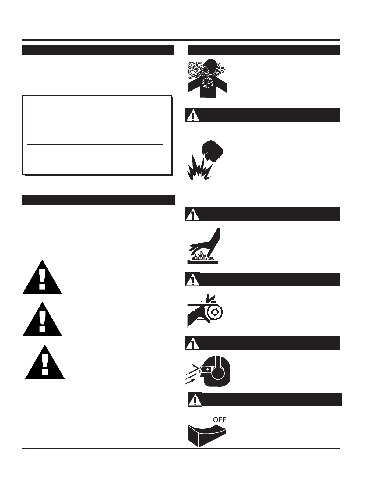
Engine exhaust gases contain poisonous
carbon monoxide. This gas is colorless and
odorless, and can cause death if inhaled.
NEVER operate this equipment in a confined
area or enclosed structure that does not
provide ample free flow air.
Explosive Fuel
Gasoline is extremely flammable, and its
vapors can cause an explosion if ignited. DO
NOT start the engine near spilled fuel or
combustible fluids. DO NOT fill the fuel tank
while the engine is running or hot. DO NOT
overfill tank, since spilled fuel could ignite if it
comes into contact with hot engine parts or
sparks from the ignition system. Store fuel in
approved containers, in well-ventilated areas
and away from sparks and flames. NEVER
use fuel as a cleaning agent.
Burn Hazards
High Temperatures – Unplug the machine and
allow to
maintenance functions. Contact with
components can cause serious burns.
cool
before performing service and
hot!
DANGER: You WILL be KILLED or
SERIOUSLY injured if you DO NOT follow
directions.
WARNING: You CAN be KILLED or
SERIOUSLY injured if you DO NOT follow
directions.
CAUTION: You CAN be injured if you
DO NOT follow directions.
Potential hazards associated with Multiquip VIBRATOR HEADS
operation will be referenced with "
appear throughout this manual, and will be referenced in
conjunction with Safety "
Message Alert Symbols
Hazard Symbols
" which
".
Rotating Parts
NEVER operate equipment with covers, or
guards removed. Keep fingers,
clothing
injury.
away from all moving parts to prevent
hands, hair
Sight and Hearing hazard
ALWAYS wear approved eye and hearing
protection.
Accidental Starting
ALWAYS place the motor ON/OFF switch
in the OFF position, when the Vibrator
Motor is not in use.
and
PAGE 6 — CV/SVA-SERIES VIBRATOR HEADS — OPERATION AND PARTS MANUAL — REV. #0 (03/22/10)
Page 7

RULES FOR SAFE OPERATION
■
WARNING:
Failure to follow instructions in this manual may
lead to serious injury or even death! This
equipment is to be operated by trained and
qualified personnel only! This equipment is
for industrial use only.
The following safety guidelines should always be used when
operating this equipment.
SAFETY
■
DO NOT operate or service this equipment
before reading this entire manual.
■
ALWAYS use proper lifting techniques when
using the the vibrator motor, flexible shaft
and vibrator head assembly.
■
ALWAYS check to make sure that the operating area is clear
before starting the vibrator motor or engine.
ALWAYS check the equipment for loosened threads or bolts
before starting.
■
NEVER use accessories or attachments, which are not
recommended by Multiquip for this equipment. Damage to
the equipment and/or injury to user may result.
EMERGENCIES
■
ALWAYS know the location of
the nearest
■
ALWAYS know the location of the
nearest and
fire extinguisher
first aid kit
.
.
■
NEVER leave the machine
■
Keep the vibrator motor or engine in proper running condition.
■
Make sure that there is no buildup of concrete, grease, oil or
debris on the equipment.
■
Fix damage to the equipment immediately and always replace
broken parts.
■
This equipment should not be operated by persons under
18 years of age.
■
NEVER operate this equipment without proper
protective clothing, shatterproof glasses, steeltoed boots and other protective devices required
by the job.
unattended
while running.
■
In emergencys
nearest phone or
Also know the phone numbers of the nearest
ambulance, doctor
information will be invaluable in the case of an
emergency.
always
know the location of the
keep a phone on the job site
and
fire department
.
. This
■
NEVER operate this equipment when not feeling
well due to fatigue, illness or taking medicine.
■
NEVER operate this equipment under the
influence or drugs or alcohol.
CV/SVA-SERIES VIBRATOR HEADS — OPERATION AND PARTS MANUAL — REV. #0 (03/22/10) — PAGE 7
Page 8
PREPARATION & OPERATION
This safety alert symbol is used to attract your
attention. Personal safety is involved. When
WARNING!WARNING!
WARNING!
WARNING!WARNING!
you see this symbol, become alert; heed its
message.
WARNING!WARNING!
WARNING!
WARNING!WARNING!
DO NOT attempt to operate this vibrator head
until the Safety and Operating Instructions for
the Electric Motor or Gasoline Power Unit and
Flexible Shaft have been read and fully
understood. Failure to do so could result in
serious bodily injury and/or property damage.
1. The vibrator motor, flexible shafting, and heads are shipped
4. When connecting the head to the casing, clean the mating
threads with an anaerobic sealant primer and allow it to air
dry for several minutes. Apply a ring of anaerobic sealant
(Loctite 271, Hernon 427 or equivalent), to the casing
threads and screw the head tightly to the casing. Wait for
one hour before using.
CAUTION!CAUTION!
CAUTION!
CAUTION!CAUTION!
from the factory ready to use.
2. Use only the combination of flexible shafting and heads
shown below in Table 1.
seziStfahS.1elbaT
LEDOM TFAHS EZISDAEH
PH1
1ID,1-VS
RE57
PH2
2ID,2-VS
RE031
PH3
3ID,3-VS
RE002
V413
V283
V283
009
0001
0031
0041
0071 .TF82
0012 .TF12
0041
0071
0012
0062
TFAHS.XAM
HTGNEL
.TF12
.TF53
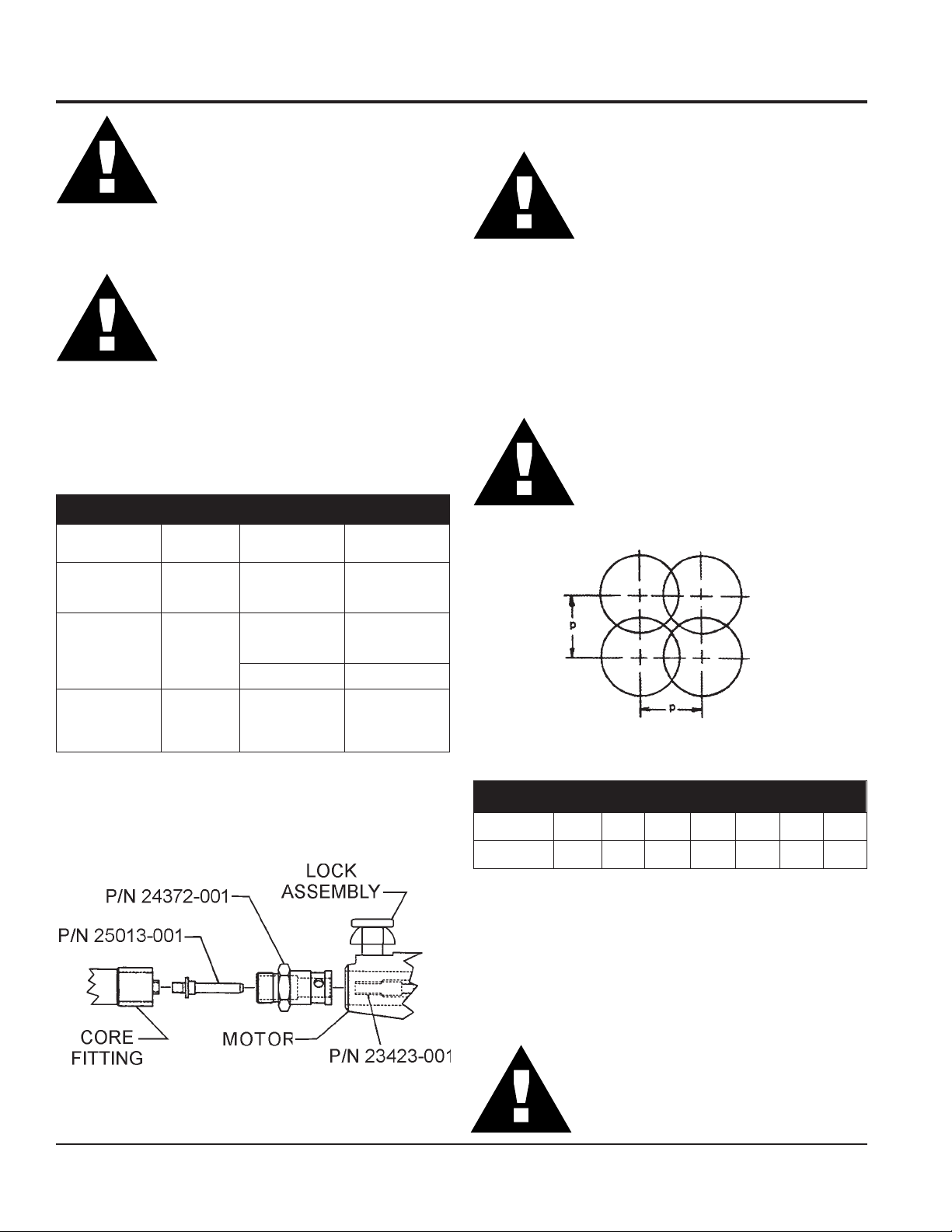
5. See Compaction Coverage Chart, (Figure 2).
MAKE CERTAIN the motor is disconnected
from the power source and the switch is in the
"OFF" position.
The vibrator head is cooled by the concrete.
Operation of the vibrator head in air longer
than 2 minutes at a time will cause overheating
of the bearings which will result in premature
head failure.
Figure 2. Compaction Coverage
with 50% Radial Overlap
3. To connect the flexible shafting to the vibrator motor see
egarevoCnoitcapmoC.2elbaT
(Figure 1). (382V Shafting shown)
daeH 009 0001 0031 0041 0071 0012 0062
noisnemiD-P "4 "2/1-5 "8 "8 "21 "41 "81
6. Immerse the head for 5 to 10 seconds, (until air stops rising),
and then withdraw it slowly to let the concrete fill the void
left by the head. The head should be completely below the
surface when vibrating to keep the head cool. When
vibrating a thin horizontal slab, the head can be used in a
horizontal position.
CAUTION!CAUTION!
CAUTION!
CAUTION!CAUTION!
If the shaft begins to helix (buckle) excessively
during operation, stop and investigate. This is
Figure 1. Shafting to Motor Connection
an indication of an overload condition.
(382V Shafting Shown)
PAGE 8 — CV/SVA-SERIES VIBRATOR HEADS — OPERATION AND PARTS MANUAL — REV. #0 (03/22/10)
Page 9

MAINTENANCE
MAINTENANCE
Reference
Number Description
1 ....................... Housing
2 ....................... Nut or Screw
3 ....................... Bearing
4 ....................... Spindle
5 ....................... Seal
6 ....................... Spacer
8 ....................... Fitting Adapter
9 ....................... Casing Adapter
10 ..................... Shim
11 ..................... Flat Washer
12 ..................... Tip
Figure 3. Head Parts
CAUTION!CAUTION!
CAUTION!
CAUTION!CAUTION!
The vibrator heads should be inspected and lubricated after
every 100 hours of use. Refer to (Figure 3).
To Disassemble a Vibrator Head:
1. Remove the flexible shaft from the head. Heat should be
applied to the threads to break down the anaerobic sealant.
This will help prevent possible damage to the threads.
Threads are left-hand.
2. Remove the casing adapter from the housing. Head should
be applied to the threads to break down the anaerobic
sealant. Threads are right-hand. (Ref. 9)
3. Remove the hardened tip from the housing. Heat should
be applied to the threads to break down the anaerobic
sealant. Threads are right-hand. (Ref. 1,12)
DO NOT allow the vibrator head to wear below
the following dimensions: See General
Specifications - page11.
CV/SVA-SERIES VIBRATOR HEADS — OPERATION AND PARTS MANUAL — REV. #0 (03/22/10) — PAGE 9
Page 10

MAINTENANCE
4. Remove the cap screw or hex nut that holds the lower
bearings in place. (Ref. 2)
5. Remove the spindle with the upper bearings still attached.
The lower bearings (tip-end) can now be removed from
the housing.(Ref. 4)
6. Remove and discard the oil seals. Note the way the seals
face so that the new seals will be installed correctly. (Ref. 5)
7. Thoroughly clean all parts with a degreasing solvent and
blow dry with air. Compressed air is not recommended for
cleaning and drying solvents out of the bearings. Bearings
should never be spun at high speed using compressed air.
(Ref. 3)
8. After cleaning, inspect all parts for wear. The bearings
should be checked by applying a light thrust load against
one bearing ring, while slowly rotating the other ring. Do
this in both directions. If any roughness or excessive
looseness is felt, the bearing should be replaced. Any
other parts that show heavy wear should also be replaced
at this time. (Ref. 3)
To Reassemble a Vibrator Head:
6. Apply a high strength anaerobic sealant to the external
threads of the casing adapter. Screw the adapter into the
housing and tighten. Threads are left-hand. (Ref. 1,9)
7. Tip head over and pour in the required amount of Lube P/
N 12000-301. Refer to General Specifications Table on
page 11.
CAUTION!CAUTION!
CAUTION!
CAUTION!CAUTION!
8. Assemble the lower bearings to the spindle. (Ref. 3)
9. Clean the tip threads and the mating threads on the housing
with anaerobic sealant primer. Allow to dry. (Ref. 1,12)
10. Apply a high strength anaerobic sealant to the tip threads
and screw the tip into the housing. Threads are right-hand.
(Ref. 1,12)
Assemble the Head to the Casing:
DO NOT use more than the specified amount
of lubricant in the vibrator head. Over-filling
will cause the head to overheat and lead to
premature failure.
1. Bearing Installation: Bearing installation should take
place under the cleanest possible conditions. Inspect the
spindle bearing seat diameter for nicks and burrs. If any
are found, carefully remove using a stone or fine file. Wipe
the bearing seat diameter with head oil to help prevent
galling while the bearing is being pressed on. While
installing the bearing, the installation force should always
be applied squarely and evenly to the inner race of the
bearing. (Ref. 3)
2. Seal Installation: Remove any nicks or burrs that will
interfere with the installation of the seal. Make sure the
seal is facing the right direction and that it is properly
positioned so that it will seat squarely without damage.
See illustration on page 12. Use an installation tool that
will apply the force evenly around the outer edge of the
seal.
3. Insert the spindle with upper bearings assembled on it,
into the housing. Using a light push fit, seat the bearings
into the housing. (Ref. 4)
4. Insert the seals into the casing adapter per the seal
installation instructions. (See page 12)
11. Clean the casing threads and the mating threads on the
head with an anaerobic sealant primer and allow to dry.
12. Apply a ring of anaerobic high strength sealand to the casing
threads. Screw the casing into the head and tighten.
13. Allow to set one hour before use.
5. Clean the casing adapter external threads and the mating
internal threads on the housing with anaerobic primer and
let dry. (Ref. 1,9)
PAGE 10 — CV/SVA-SERIES VIBRATOR HEADS — OPERATION AND PARTS MANUAL — REV. #0 (03/22/10)
Page 11

SPECIFICATIONS
ledoM 009 0001 0031 0041 0071 0012 0062
SPECIFICATIONS
SNOITACIFICEPSLARENEG.3ELBAT
thgieW
htgneL "51 "41 "51 "51 "41 "31 "31
retemaiDgnirutcafunaM 8/7 61/1-1 8/3-1 8/3-1 61/11-1 8/1-2 8/5-2
retemaiDraeWmuminiM 61/31 1 4/1-1 4/1-1 61/9-1 8/7-1 4/1-2
yticapaCebuLdaeH .zo2/1 .zo2/1 .zo2/1 .zo2/1 .zo4/3 .zo1 .zo2/1-1
.bl1
.zo11
.bl2
.zo6
.sbl4
.zo11
.sbl4
.zo01
.sbl6
.zo4
.sbl8
.zo11
.sbl21
.zo01
CV/SVA-SERIES VIBRATOR HEADS — OPERATION AND PARTS MANUAL — REV. #0 (03/22/10) — PAGE 11
Page 12

SEAL INSTALLATION
SEAL INSTALLATION
HEAD END
Figure 4. Seal Installation
■
Seal outer case to face outer case of first seal pressed into
casing adapter.
■
Depending on vibrator head model, casing adapter may not
appear exactly as shown.
CAUTION!CAUTION!
CAUTION!
CAUTION!CAUTION!
Improper seal installation may cause
premature head failure.
SHAFT END
1. Seal lip to face vibrator shaft end.2. Seal lip to face vibrator head end.
PAGE 12 — CV/SVA-SERIES VIBRATOR HEADS — OPERATION AND PARTS MANUAL — REV. #0 (03/22/10)
Page 13

NOTES
CV/SVA-SERIES VIBRATOR HEADS — OPERATION AND PARTS MANUAL — REV. #0 (03/22/10) — PAGE 13
Page 14

VIBRATOR HEAD ASSY.
VIBRATOR HEAD ASSY.
PAGE 14 — CV/SVA-SERIES VIBRATOR HEADS — OPERATION AND PARTS MANUAL — REV. #0 (03/22/10)
Page 15

VIBRATOR HEAD ASSY.
.ONMETI .ONTRAP NOITPIRCSED 009 0001 0031 0041 0071 0012 0062
VIBRATOR HEAD ASSY.
-
-
-
-
-
-
-
1
1
1
1
1
1
2
2
505-20371
105-96361
105-71361
105-61361
505-99651
105-10361
105-47261
200-30371
100-17361
100-02361
100-00751
100-50361
100-97261
400-33280
500-33280
009LEDOM
0001LEDOM
0031LEDOM
0041LEDOM
0071LEDOM
0012LEDOM
0062LEDOM
GNISUOH
GNISUOH
GNISUOH
GNISUOH
GNISUOH
GNISUOH
02-4/1OCPIRGTUN
81-61/5OCPIRGTUN
X
X
X
X
X
X
X
1
1
1 1
1
1
1
1
1
2
2
2
3
3
3
3
3
3
4
4
4
4
4
4
600-79280
500-11560
600-31560
200-98190
104-39001
400-39391
300-39391
100-39391
200-39391
200-99111
100-48491
100-17881
100-00962
100-58781
100-90881
GNIRAEB
GNIRAEB
GNIRAEB
GNIRAEB
GNIRAEB
GNIRAEB
ELDNIPS
ELDNIPS
ELDNIPS
ELDNIPS
ELDNIPS
ELDNIPS
42-8/3OCPIRGTUN
8/5x42-8/3SCHH
4/3x02-2/1SCHH
4
1
1 1
1 1
1
4
4 4
4
4
4
1
1 1
1
1
1
CV/SVA-SERIES VIBRATOR HEADS — OPERATION AND PARTS MANUAL — REV. #0 (03/22/10) — PAGE 15
Page 16

VIBRATOR HEAD ASSY.
VIBRATOR HEAD ASSY.
PAGE 16 — CV/SVA-SERIES VIBRATOR HEADS — OPERATION AND PARTS MANUAL — REV. #0 (03/22/10)
Page 17

VIBRATOR HEAD ASSY.
.ONMETI .ONTRAP NOITPIRCSED 009 0001 0031 0041 0071 0012 0062
VIBRATOR HEAD ASSY.
5
5
5
5
5
5
6
8
8
8
8
9
9
9
9
650-10070
120-10070
920-10070
640-10070
750-10070
910-10070
100-55062
100-05062
100-57361
100-82361
100-72361
100-94062
200-47361
100-52361
100-62361
LAES
LAES
LAES
LAES
LAES
LAES
RECAPS 1
RETPADAGNITTIF 1
RETPADAGNITTIF 1
RETPADAGNITTIF
RETPADAGNITTIF
RETPADAGNISAC
RETPADAGNISAC
RETPADAGNISAC
RETPADAGNISAC
2
2
2 2
2
2
2
1
1
1
1
1
1
9
9
9
01
01
01
01
11
11
21
21
21
21
21
21
100-40761
100-30361
100-87261
520-60911
210-60911
510-60911
020-60911
MIHS
MIHS
MIHS
MIHS
600-03070
800-03070
100-40211
100-86361
100-81361
100-50751
100-20361
100-77261
PIT
PIT
PIT
PIT
PIT
PIT
RETPADAGNISAC
RETPADAGNISAC
RETPADAGNISAC
2 2
2 2
8/3REHSAWTALF
2/1REHSAWTALF
1
1
1 1
1
1
1
2 2
2
1 1
1
1
1
1
CV/SVA-SERIES VIBRATOR HEADS — OPERATION AND PARTS MANUAL — REV. #0 (03/22/10) — PAGE 17
Page 18

Effective: July 1, 2000
TERMS AND CONDITIONS OF SALE
PAYMENT TERMS
Terms of payment for parts are net 30 days.
FREIGHT POLICY
All parts orders will be shipped collect or
prepaid with the charges added to the invoice.
All shipments are F.O.B. point of origin.
Multiquip’s responsibility ceases when a
signed manifest has been obtained from the
carrier, and any claim for shortage or damage
must be settled between the consignee and
the carrier.
MINIMUM ORDER
The minimum charge for orders from Multiquip
is $15.00 net. Customers will be asked for
instructions regarding handling of orders not
meeting this requirement.
RETURNED GOODS POLICY
Return shipments will be accepted and
credit will be allowed, subject to the following
provisions:
A Returned Material Authorization 1.
must be approved by Multiquip prior to
shipment.
To obtain a Return Material Authorization, 2.
a list must be provided to Multiquip
Parts Sales that defines item numbers,
quantities, and descriptions of the items
to be returned.
The parts numbers and descriptions a.
must match the current parts price
list.
The list must be typed or computer b.
generated.
The list must state the reason(s) c.
for the return.
The list must reference the sales d.
order(s) or invoice(s) under
which the items were originally
purchased.
The list must include the name e.
and phone number of the person
requesting the RMA.
A copy of the Return Material Authorization 3.
must accompany the return shipment.
Freight is at the sender’s expense. All 4.
parts must be returned freight prepaid to
Multiquip’s designated receiving point.
Parts must be in new and resalable 5.
condition, in the original Multiquip
package (if any), and with Multiquip part
numbers clearly marked.
The following items are not returnable:6.
Obsolete parts. (If an item is in the a.
price book and shows as being
replaced by another item, it is
obsolete.)
Any parts with a limited shelf life b.
(such as gaskets, seals, “O” rings,
and other rubber parts) that were
purchased more than six months
prior to the return date.
Any line item with an extended c.
dealer net price of less than
$5.00.
Special order items.d.
Electrical components.e.
Paint, chemicals, and lubricants.f.
Decals and paper products.g.
Items purchased in kits.h.
The sender will be notified of any material 7.
received that is not acceptable.
Such material will be held for five 8.
working days from notification, pending
instructions. If a reply is not received
within five days, the material will be
returned to the sender at his expense.
Credit on returned parts will be issued 9.
at dealer net price at time of the original
purchase, less a 15% restocking
charge.
In cases where an item is accepted, for 10.
which the original purchase document
can not be determined, the price will be
based on the list price that was effective
twelve months prior to the RMA date.
Credit issued will be applied to future 11.
purchases only.
PRICING AND REBATES
Prices are subject to change without prior
notice. Price changes are effective on a
specific date and all orders received on or
after that date will be billed at the revised price.
Rebates for price declines and added charges
for price increases will not be made for stock
on hand at the time of any price change.
Multiquip reserves the right to quote and
sell direct to Government agencies, and to
Original Equipment Manufacturer accounts
who use our products as integral parts of their
own products.
SPECIAL EXPEDITING SERVICE
A $35.00 surcharge will be added to the
invoice for special handling including bus
shipments, insured parcel post or in cases
where Multiquip must personally deliver the
parts to the carrier.
LIMITATIONS OF SELLER’S LIABILITY
Multiquip shall not be liable hereunder for
damages in excess of the purchase price of
the item with respect to which damages are
claimed, and in no event shall Multiquip be
liable for loss of profit or good will or for any
other special, consequential or incidental
damages.
LIMITATION OF WARRANTIES
No warranties, express or implied, are
made in connection with the sale of parts or
trade accessories nor as to any engine not
manufactured by Multiquip. Such warranties
made in connection with the sale of new,
complete units are made exclusively by a
statement of warranty packaged with such
units, and Multiquip neither assumes nor
authorizes any person to assume for it
any other obligation or liability whatever in
connection with the sale of its products. Apart
from such written statement of warranty,
there are no warranties, express, implied or
statutory, which extend beyond the description
of the products on the face hereof.
Effective: February 22, 2006
PAGE 18 — CV/SVA-SERIES VIBRATOR HEADS — OPERATION AND PARTS MANUAL — REV. #0 (03/22/10)
Page 19

NOTES
CV/SVA-SERIES VIBRATOR HEADS — OPERATION AND PARTS MANUAL — REV. #0 (03/22/10) — PAGE 19
Page 20

OPERATION AND PARTS MANUAL
©
HERE’S HOW TO GET HELP
PLEASE HAVE THE MODEL AND SERIAL
NUMBER ON-HAND WHEN CALLING
UNITED STATES
Multiquip Corporate Office MQ Parts Department
18910 Wilmington Ave.
Carson, CA 90746
Contact: mq@multiquip.com
Mayco Parts Warranty Department
Tel. (800) 421-1244
Fax (800) 537-3927
800-427-1244
310-537-3700
Fax: 800-672-7877
Fax: 310-637-3284
800-306-2926
310-537-3700
Service Department Technical Assistance
800-421-1244
310-537-3700
Fax: 800-672-7877
Fax: 310-637-3284
Fax: 310-537-4259 800-478-1244 Fax: 310-631-5032
800-421-1244, Ext. 279
310-537-3700, Ext. 279
Fax: 310-537-1173
MEXICO UNITED KINGDOM
MQ Cipsa Multiquip (UK) Limited Head Office
Carr. Fed. Mexico-Puebla KM 126.5
Momoxpan, Cholula, Puebla 72760 Mexico
Contact: pmastretta@cipsa.com.mx
Tel: (52) 222-225-9900
Fax: (52) 222-285-0420
Unit 2, Northpoint Industrial Estate,
Global Lane,
Dukinfield, Cheshire SK16 4UJ
Contact: sales@multiquip.co.uk
Tel: 0161 339 2223
Fax: 0161 339 3226
CANADA
Multiquip
4110 Industriel Boul.
Laval, Quebec, Canada H7L 6V3
Contact: jmartin@multiquip.com
COPYRIGHT 2010, MULTIQUIP INC.
Multiquip Inc and the MQ logo are registered trademarks of Multiquip Inc. and may not be used, reproduced, or altered without written permission. All other trademarks are the property
of their respective owners and used with permission.
This manual
The information and specifications included in this publication were in effect at the time of approval for printing. Illustrations, descriptions, references and technical data contained in
this manual are for guidance only and may not be considered as binding. Multiquip Inc. reserves the right to discontinue or change specifications, design or the information published
in this publication at any time without notice and without incurring any obligations.
MUST accompany the equipment at all times. This manual is considered a permanent part of the equipment and should remain with the unit if resold.
Tel: (450) 625-2244
Tel: (877) 963-4411
Fax: (450) 625-8664
Your Local Dealer is:
 Loading...