

Page 1

OPERATION AND PARTS MANUAL
MODEL DM15A9C
CORE DRILL MOTOR
&
MODEL CDM2CSA
DRILL RIG STAND
Revision #1 (11/09/05)
To find the latest revision of this
publication, visit our website at:
www.multiquip.com
THIS MANUAL MUST ACCOMPANY THE EQUIPMENT AT ALL TIMES.
Page 2
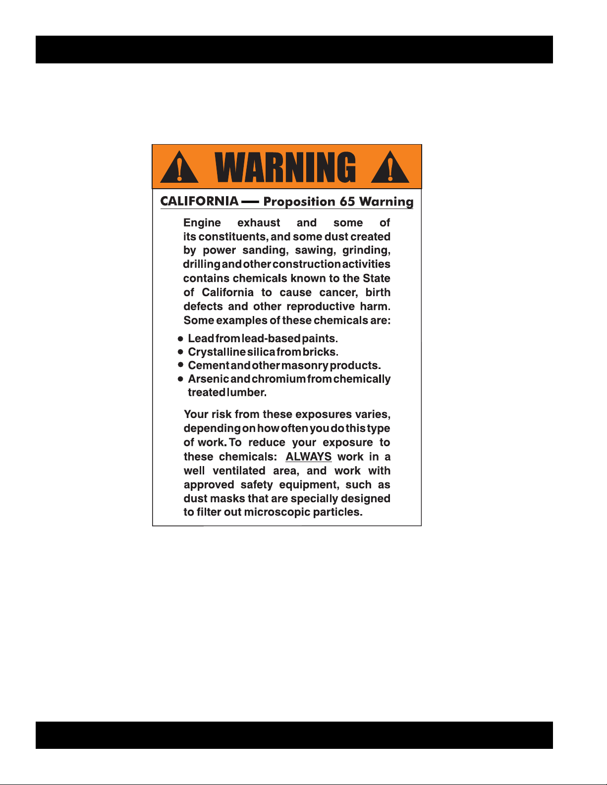
DM15A9C/CDM2CSA — PROPOSITION 65 WARNING
Page 3
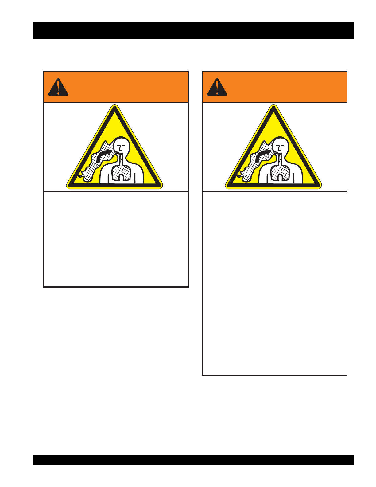
Grinding/cutting/drilling of masonry, concrete, metal and
other materials with silica in their composition may give
off dust or mists containing crystalline silica. Silica is a
basic component of sand, quartz, brick clay, granite and
numerous other minerals and rocks. Repeated and/or
substantial inhalation of airborne crystalline silica can
cause serious or fatal respiratory diseases, including
silicosis. In addition, California and some other
authorities have listed respirable crystalline silica as a
substance known to cause cancer. When cutting such
materials, always follow the respiratory precautions
mentioned above.
WARNING
Grinding/cutting/drilling of masonry, concrete, metal and
other materials can generate dust, mists and fumes
containing chemicals known to cause serious or fatal
injury or illness, such as respiratory disease, cancer,
birth defects or other reproductive harm. If you are
unfamiliar with the risks associated with the particular
process and/or material being cut or the composition of
the tool being used, review the material safety data
sheet and/or consult your employer, the material
manufacturer/supplier, governmental agencies such as
OSHA and NIOSH and other sources on hazardous
materials. California and some other authorities, for
instance, have published lists of substances known to
cause cancer, reproductive toxicity, or other harmful
effects.
Control dust, mist and fumes at the source where
possible. In this regard use good work practices and
follow the recommendations of the manufacturers or
suppliers, OSHA/NIOSH, and occupational and trade
associations. Water should be used for dust
suppression when wet cutting is feasible. When the
hazards from inhalation of dust, mists and fumes cannot
be eliminated, the operator and any bystanders should
always wear a respirator approved by NIOSH/MSHA for
the materials being used.
WARNING
SILICOSIS WARNING RESPIRATORY HAZARDS
DM15A9C/CDM2CSA — SILICOSIS WARNING
DM15A9C/CDM2CSA — OPERATION AND PARTS MANUAL — REV. # 0 (08/05/05) — PAGE 3
Page 4
DM15A9C/CDM2CSA— TABLE OF CONTENTS
Multiquip DM15A9C Electric
Powered Core Drill and
CDM2CSA Drilling Rig
Proposition 65 Warning ............................................. 2
Silicosis Warning ....................................................... 3
Table Of Contents ..................................................... 4
Parts Ordering Procedures ....................................... 5
Safety Message Alert Symbols ................................. 6
Rules For Safe Operation ...................................... 7-9
General Information ........................................... 10-11
Specifications/Dimensions(DM15A9C) ................... 12
Dimensions (CDM2CSA) ........................................ 13
Components (CDM2CSA Drilling Rig) .................... 14
Components (DM15A9C Electric Motor) ................ 14
Pre-Set-up .......................................................... 16-20
Operation ................................................................ 21
Shutdown ................................................................ 22
Maintenance ........................................................... 23
Troubleshooting ...................................................... 24
Explanation Of Code In Remarks Column .............. 26
Suggested Spare Parts ........................................... 27
Nameplate and Decals....................................... 28-29
Electric Motor Assembly..................................... 30-33
Drilling Rig Assembly ......................................... 34-35
Cradle Assembly ................................................ 36-37
Tools ................................................................... 38-39
NOTE
NOTE
As a continuing effort to
update our parts book,
contact the MULTIQUIP
literature department for the
latest revision of your
"Operation and Parts
Manual"
Specification and part number
are subject to change without
notice.
Terms and Conditions of Sale ................................. 40
PAGE 4 —DM15A9C/CDM2CSA — OPERATION AND PARTS MANUAL — REV. #1 (11/09/05)
Page 5
DM15A9C/CDM2CSA — PARTS ORDERING PROCEDURES
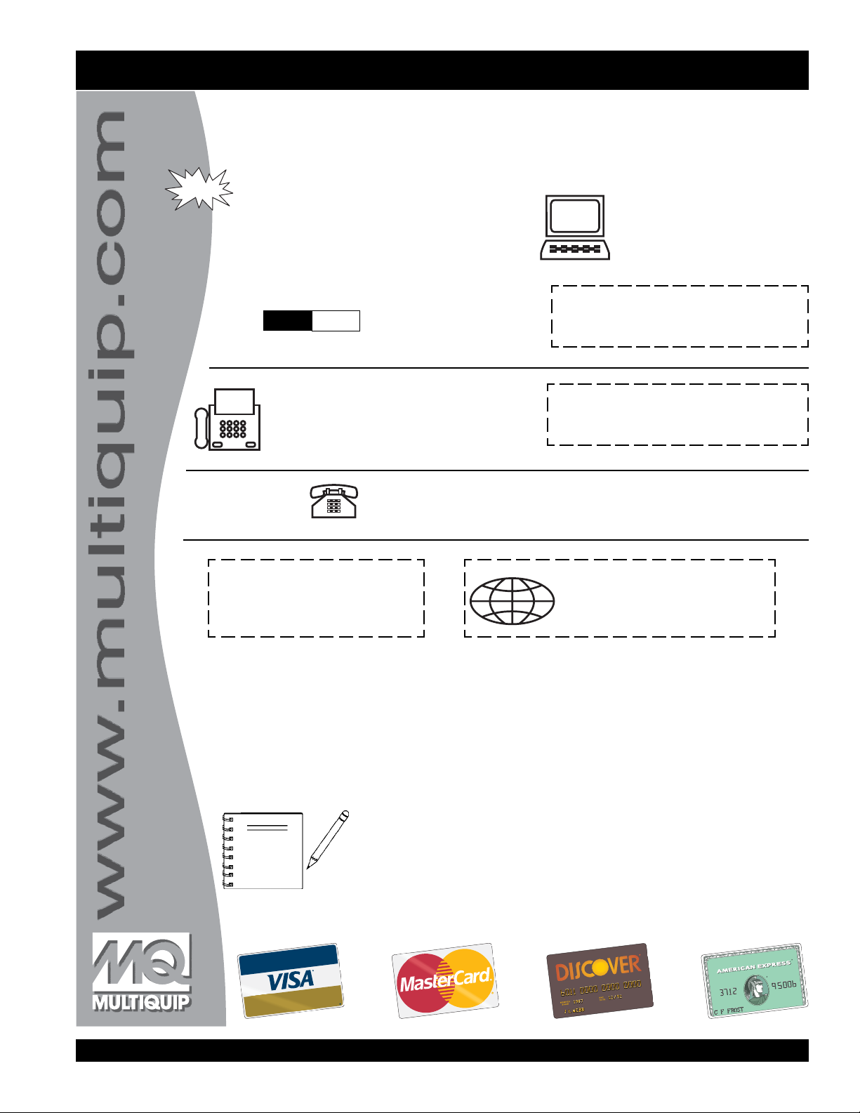
Ordering parts has never been easier!
Choose from three easy options:
Best Deal!
Order via Internet (Dealers Only):
Order parts on-line using Multiquip’s SmartEquip website!
■
View Parts Diagrams
■
Order Parts
■
Print Specification Information
Goto www.multiquip.com and click on
Order Parts
to log in and save!
Order via Fax (Dealers Only):
All customers are welcome to order parts via Fax.
Domestic (US) Customers dial:
1-800-6-PARTS-7 (800-672-7877)
Order via Phone:
Non-Dealer Customers:
Contact your local Multiquip Dealer for
parts or call 800-427-1244 for help in
locating a dealer near you.
If you have an MQ Account, to obtain a
Username and Password, E-mail us at:
parts@multiquip.com.
To obtain an MQ Account, contact your
District Sales Manager for more information.
Use the
internet
on
Standard orders
and qualify for a 5% Discount
for all orders which include
complete part numbers.*
Fax
your order in and qualify for a 3% Discount
on
Standard orders
for all orders which include
complete part numbers.*
Domestic (US) Dealers Call:
1-800-427-1244
International Customers
their local Multiquip Representatives for
Parts Ordering information.
Note: Discounts Are Subject To Change
Note: Discounts Are Subject To Change
should contact
When ordering parts, please supply:
❒❒
❒
Dealer Account Number
❒❒
❒❒
❒
Dealer Name and Address
❒❒
❒❒
❒
Shipping Address (if different than billing address)
❒❒
❒❒
❒
Return Fax Number
❒❒
❒❒
❒
Applicable Model Number
❒❒
❒❒
❒
Quantity, Part Number and Description of Each Part
❒❒
NOTE
Unless otherwise indicated by customer, all orders are treated as
within 24 hours. We will make every effort to ship
if received prior to 2PM PST.
www.multiquip.com
WE ACCEPT ALL MAJOR CREDIT CARDS!
DM15A9C/CDM2CSA — OPERATION AND PARTS MANUAL — REV. #1 (11/09/05) — PAGE 5
❒❒
❒
Specify Preferred Method of Shipment:
❒❒
✓
Fed Ex/UPS
■
■
■ Next Day
■
Stock Orders
✓ DHL
Priority One
Ground
Second/Third Day
✓
Tr u c k
Standard Orders
Air Shipments
the same day the order is received,
must be noted on fax or web order form.
and will ship
Page 6
DM15A9C/CDM2CSA— SAFETY MESSAGE ALERT SYMBOLS
FOR YOUR SAFETY AND THE SAFETY OF OTHERS!
Safety precautions should be followed at all times when operating
this equipment. Failure to read and understand the Safety
Messages and Operating Instructions could result in injury to
yourself and others.
This Operation and Parts Manual
NOTE
Before using this core drill stand and electric motor, ensure
that the operating individual has read and understands all
instructions in this manual.
SAFETY MESSAGE ALERT SYMBOLS
The three (3) Safety Messages shown below will inform you
about potential hazards that could injure you or others. The
Safety Messages specifically address the level of exposure
to the operator, and are preceded by one of three words:
DANGER, WARNING, or CAUTION.
DANGERDANGER
DANGER
DANGERDANGER
You WILL be
NOT follow directions.
KILLED
has been developed to provide
complete instructions for the safe
and efficient operation of the
Models DM15A9C/CDM2SA
Core Drill Motor and Drill Rig
or
SERIOUSLY
injured if you DO
MQ
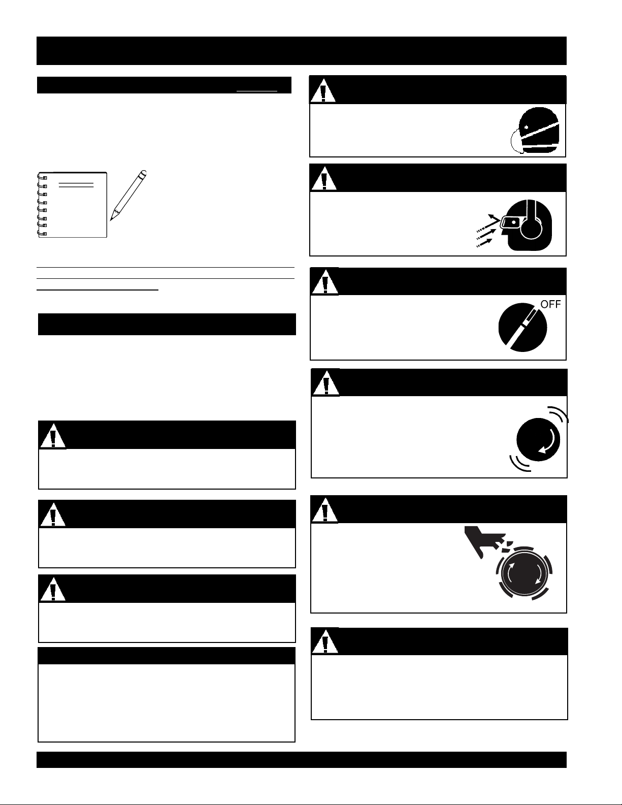
ALWAYS wear approved
protection when required.
ALWAYS wear approved eye and
hearing protection.
ALWAYS place the core-drill's ON/OFF
switch in the OFF position when the drill
is not in use.
NEVER tamper with the factory settings
of the core drill. Personal injury and
damage to the core drill can result if
operating in speed ranges above
maximum allowable.
WARNING - Respiratory Hazards
respiratory
CAUTION - Eye and Hearing Hazards
CAUTION - Accidental Starting Hazards
CAUTION - Over Speed Conditions
WARNINGWARNING
WARNING
WARNINGWARNING
You CAN be
NOT follow directions.
CAUTION
You CAN be
HAZARD SYMBOLS
Potential hazards associated with the operation of the
DM15A9C (electric motor)
rig)
will be referenced with Hazard Symbols which appear
throughout this manual, and will be referenced in
conjunction with Safety Message Alert Symbols.
KILLED
CAUTIONCAUTION
CAUTION
CAUTIONCAUTION
INJURED
PAGE 6 —DM15A9C/CDM2CSA — OPERATION AND PARTS MANUAL — REV. #1 (11/09/05)
or
SERIOUSLY
if you DO NOT follow directions.
and MQ CDM2CSA (drill
injured if you DO
Rotating drill bit can cut and
crush. Keep hands and feet
clear.
Other important messages are provided throughout this
manual to help prevent damage to your drill, other property,
or the surrounding environment.
CAUTION - Rotating Drill Bit
CAUTION - Equipment Damage Hazards
Page 7
DM15A9C/CDM2CSA— RULES FOR SAFE OPERATION
■
DANGERDANGER
DANGER
DANGERDANGER
Failure to follow instructions in this manual may lead to
serious injury or even death! This equipment is to be
operated by trained and qualified personnel only! This
equipment is for industrial use only.
The following safety guidelines should always be used when
MQ
operating the
(drill rig)
GENERAL SAFETY
■
DO NOT operate or service this
equipment before reading entire manual.
■
This equipment should not be operated
by persons under 18 years of age.
■
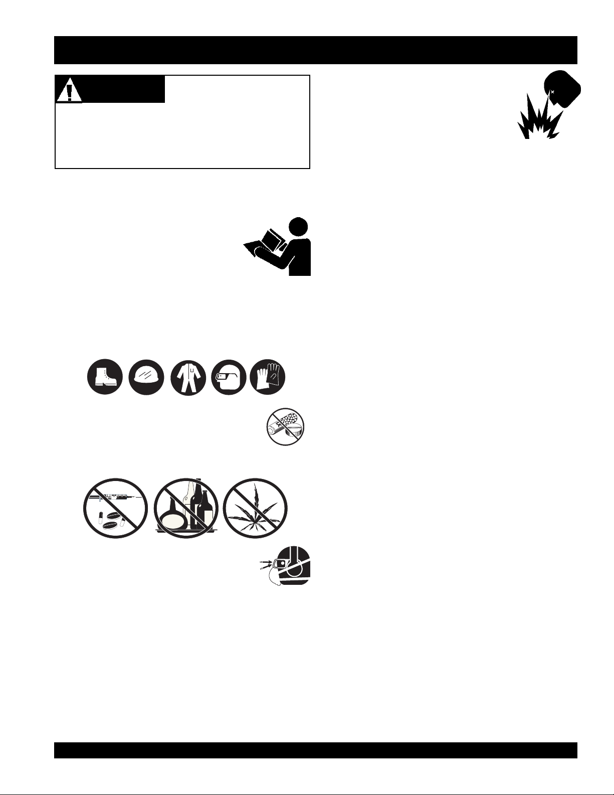
NEVER operate this equipment without proper protective
clothing, shatterproof glasses, steel-toed boots, hard hat
and other protective devices required by the job.
DM15A9C (electric motor) and
Read this manual!
CDM2SA
NEVER operate the core drill in an
explosive atmosphere or near combustible
materials.The electric motor of this coredrill emits sparks during operation and
shut-down. A explosion or fire could result
causing severe
make contact with combustibe or explosive materials.
■
Maintain this equipment in a safe operating condition at
all times.
■
Keep bystanders, children and vistors away while
operating the core drill. Distractions can cause you to
loose control.
■
DO NOT wear wear loose clothing or jewelry. Contain
long hair. Keep your hair, clothing, and gloves away from
moving parts.
■
ALWAYS store equipment properly when it is not being
used. Equipment should be stored in a clean, dry location
out of the reach of children.
■
ALWAYS be sure the operator is familiar with proper
safety precautions and operation techniques before using
core drill.
bodily harm or even death if the sparks
■
■
NEVER operate this equipment when not feeling
well due to fatigue, illness or taking medicine.
■
NEVER operate this equipment under the influence of
drugs
■
ALWAYS wear proper respiratory (mask),
hearing and eye protection equipment when
operating the core drill.
■
Whenever necessary, replace nameplate, operation and
safety decals when they become difficult read.
■
Manufacturer does not assume responsibility for any
accident due to equipment modifications.
■
NEVER use accessories or attachments, which are not
recommended by Multiquip for this equipment. Damage
to the equipment and/or injury to user may result.
or
alcohol
.
■
■
■
■
■
■
■
■
ALWAYS keep work area clean and free of foreign matter
and debris. Also keep work area well lit.
Avoid accidental starting. Make sure power ON/OFF
switch is off before applying power.
NEVER leave the core drill unattended. When not in use
always unplug the core drill from power source.
ALWAYS remove any adjusting keys or wrenches before
turing the core drill on. A wrench or key that is left attached
to the rotating part of the core drill may result in personal
injury.
DO NOT overreach. Keep proper footing and balance at
all times. Proper footing and balance enables better
control of the core drill in unexpected situations.
Keep all
from the equipment at all times.
Become familiar with the components of the core drill
before operating.
ALWAYS replace any worn or damaged warning decals.
NEVER touch drill bit cutting edges during operation. Also
allow drill bit a sufficient amount of time to cool before
touching.
inexperienced
and
unauthorized
people away
DM15A9C/CDM2CSA — OPERATION AND PARTS MANUAL — REV. #1 (11/09/05) — PAGE 7
Page 8

DM15A9C/CDM2CSA — RULES FOR SAFE OPERATION
■
Maintain the core drill and drill bits with care. Make sure
bit maintains good diamond exposure. A dull bit will cause
glazing.
■
NEVER drill into a work piece that is not secured.
■
Use this core drill only for its intended purpose. DO NOT
use this core drill for applications not recommended.
■
Inspect the drill after each use. Replace any damaged or
worn parts immediately. DO NOT use a defective coredrill.
■
NEVER cover the air vents on the body of the core drill.
ALWAYS leave these vents exposed. These vents are
essential for the cooling of the electric motor. NEVER
place tape over the vent to keep out dust.
■
If a malfunction occurs, immediately unplug the core drill
from the power source and correct the problem. If the
problem can not be corrected, contact your nearest MQ
service center.
■
DO NOT force your core drill. Excerting excessive force
while drilling will damage your machine and is hazardous.
■
ALWAYS make sure drill bit is installed securely so that
it will not slip or fall out. It is hazardous to use a core drill
with a loose fitted drill bit.
■
Some materials contain chemicals which may be
toxic.Take precautions to prevent dust inhalation and skin
contact.
ELECTRICAL SAFETY
■
ALWAYS test the
operating. The purpose of this switch is to shut down the
electric motor.
■
NEVER use a extension cord that is frayed or damaged
where the insulation has been cut.
ON/OFF
switch on the core drill before
■
■
■
■
■
■
■
■
When connecting the core drill to a power receptacle,
make sure the receptacle circuit is connected to either a
GFCI receptacle or a receptacle protected by a 20 amp
circuit breaker.
When plugging the core-drill into a power receptacle, check
the nameplate for the correct operating voltage. Operating
the core drill at the wrong voltage will damage the electric
motor. ALWAYS read the nameplate before applying
power.
This core drill is equipped with a 3-prong male power
plug. DO NOT use a 2-prong adapter when plugging into
a wall outlet. This will defeat the purpose of the ground
circuit. If the plug does not fit into the receptacle, contact
a qualified electrician to install a 3-conductor wall
receptacle (outlet).
Avoid body contact with grounded surfaces such as pipes,
radiators, ranges and refrigerators. There is an increased
risk of electrical shock if your body is grounded.
DO NOT expose the the core drill to rain or wet conditions.
Water entering the drill wii increase the risk of electrical
shock.
When operating the core drill outside, be sure to use the
apporpriate outdoor extension cord. This type of extension
cord reduces the risk of electrical shock.
ALWAYS be on the lookout for hidden wiring, the
possibility exists of the drill bit making contact with hidden
wiring. Contact with a "live" wire can cause electrical
shock to the operator.
ALWAYS remove the AC power cord from the power
source before performing any service or maintenance on
the core drill. This preventative safety measure reduces
the possibility of accidental starting.
■
NEVER carry the core drill by its power cord or disconnect
it by yanking the cord from the power outlet.
■
ALWAYS make certain that the proper extension cord
has been selected for the job. See Table 1.
■
NEVER allow power cord to
■
NEVER
stand in water
PAGE 8 —DM15A9C/CDM2CSA — OPERATION AND PARTS MANUAL — REV. #1 (11/09/05)
lay in wate
while operating the core drill.
r.
Page 9
DM15A9C/CDM2CSA— RULES FOR SAFE OPERATION
TRANSPORTING
■
ALWAYS secure the core drill and drill rig with rope or
tie-downs when transporting is required.
■
ALWAYS wrap power cord neatly to avoid damage.
■
ALWAYS place wrenches in a safe location where they
can be located easily. Keep tools clean.
MAINTENANCE
■
NEVER lubricate components or attempt service on a
running core drill.
■
ALWAYS allow the core drill a proper amount of time to
cool before servicing.
■
Keep the core drill in proper running condition.
■
Fix damage to the core drill immediately and always
replace broken parts. Replace with only MQ
recommended parts.
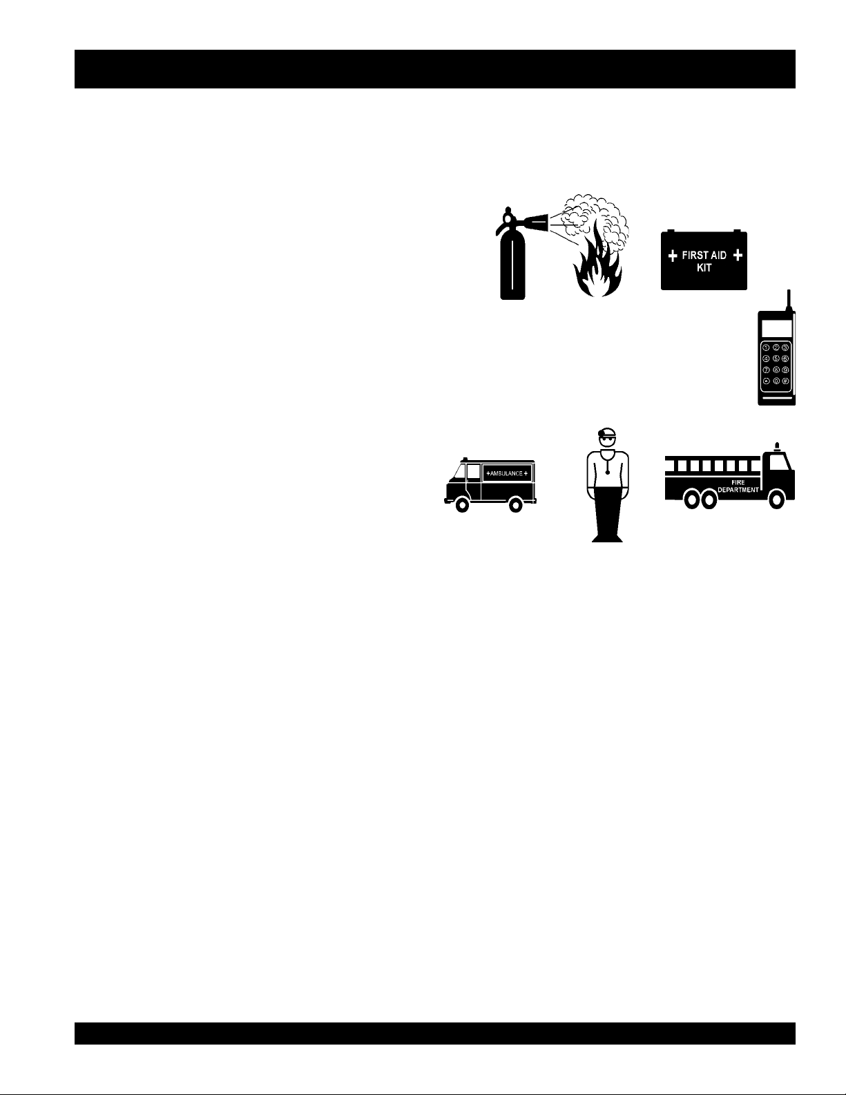
EMERGENCIES
■
■
ALWAYS know the location of the nearest
extinguisher
In emergencies
nearest phone or
Also know the phone numbers of the nearest
ambulance, doctor
information will be invaluable in the case of an
emergency.
and first aid kit.
always
know the location of the
keep a phone on the job site
and
fire department
. This
fire
.
DM15A9C/CDM2CSA — OPERATION AND PARTS MANUAL — REV. #1 (11/09/05) — PAGE 9
Page 10
DM15A9C/CDM2CSA — GENERAL INFORMATION
APPLICATION
MQ DM-15A9C Stationary Core Drill Motor
The
be used with the
MQ CDM-2CSA Lightweight Drilling Rig
is designed to
. The
core drill motor is intended only for wet drilling applications involving
concrete type materials. Up to 9-inch (229 mm) diameter holes can
wet
be drilled for
drilling applications using
bits. All MQ wet drill bits allow for a
standard
14-inch cutting depth
MQ wet drill
. Dry
cutting applications are not recommended with this unit.
Power Plant
The MQ DM-15A9C is powered by a 120 VAC 2-speed electric
motor @15 amps. Min/Max RPM's is 600/ 1200 . The unit weighs
20.0 lbs (9.0 kg.)
Features
This unit is equipped with the following:
Threads/Adapters
The MQ DM15A9C core drill is supplied with a 1-1/4" X 7 thread
shaft to be used specifically with the Multiquip wet drill bits. If it ever
becomes necessary to reduce the shaft size, a 5/8" X11 reducer
is available as an option.
Supplied Tools
■
17, 19, 36 and 46 mm wrenches
Extension Cords
Use only 3-prong type extension cords with grounding pin. Always
connect extension cord to a matching 3-prong receptacle. NEVER
use a 3 to 2 prong adapter, this type of adapter will defeat the ground
circuit protection capability. Always use an extension cord of
adequate current carrying cability. Use Table 1 as a guidline when
selecting the proper extension cord.
■
2-Speed Electric Motor
■
Internal Water Feed System
■
Vacuum Pump (Option)
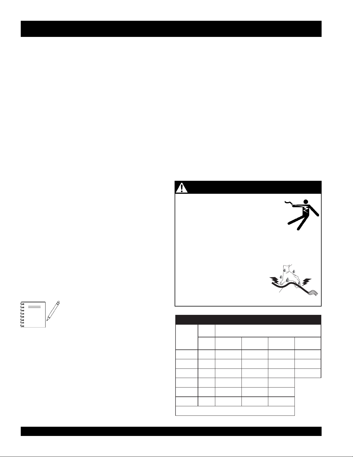
DANGER - ELECTROCUTION HAZARDS
During operation of this core drill, there
exists the possibility of
electrical shock or burn,
Standard MQ Drill Bits (Wet)
This core drill can use the following series of wet drilling bits:
■
GCB Series – economy quality small jobs.
■
GB Series – standard quality small to mid-size jobs.
■
PRB Series – premium quality for fast speeds.
■
PCB Series – super premimum quality and long life.
■
PCB Series – pro quality, high steel content and
extremely hard aggregate small jobs.
NOTE
Contact the MQ Sales Department for the
core drill bit that best fits your application or
accesssories.
severe bodily harm
To avoid these hazards:
NEVER use damaged or worn cables when plugging the
core drill into an AC power receptacle.
NEVER grab or touch a live power
cord with wet hands.
NEVER stand in water and touch a
live power cord.
nitnerruC
serepmA
5.2003.tf0001.t
5006.tf005.tf003.tf002.tf521
5.7009.tf053.tf002.tf521.tf001
010021.tf052.tf051.tf001
510081.tf051.tf001.tf56
020042.tf521.tf57.tf05
electrocution,
which can cause
or even
nIdaoL
sttaW
021tA
stloV
DEATH!
WET
HANDS
POWER
CORD
(POWER ON)
htgneLelbaCelbawollAmumixaM
eriW01#eriW21#eriW41#eriW61#
f006.tf573.tf052
.egatlovwolmorftlusernacegamadtnempiuqE:NOITUAC
)noitarepOesahPelgniS,zH06(noitceleSelbaC.1elbaT
PAGE 10 —DM15A9C/CDM2CSA — OPERATION AND PARTS MANUAL — REV. #1 (11/09/05)
Page 11

DM15A9C/CDM2CSA — GENERAL INFORMATION
Operator Technique
Always drill with consistent uniform pressure. NEVER subject the
drill bit to sudden impacts. Uneven pressure can damage a bit. Slow
bit penetration leads to bit glazing. Excessive drill pressure can
overload the drill motor. Always try and let the drill bit do the work and
try not to force the bit through the material.
If vibration occurs while drilling do the following:
■
Stop drilling
■
Turn motor off
■
Check for loose nuts or bolts on the equipment
■
Check for bit runout. Replace if necessary
Drilling Performance
Factors that influence core drilling:
■
Amount of water flow
■
Condition of equipment
■
RPM of electric drill motor
■
Amount and size steel
■
Age of concrete
■
Aggregate (size, type, hardness, abrasiveness)
■
Operator technique
■
Bit runout
Water
Water acts as a coolant, eliminating the heat caused by the friction
of the drilling. This preserves the integrity of the drill bit. Without
water acting as a coolant, the heat buildup during drilling will greatly
reduce the life cycle of the drill bit.
During drilling water flushes loose, abrasive particles created during
drilling. These particles consist of aggregate, sand, and various
metals from embedded steel. The hole must be free of debris to
allow the core bit to work.
If loose particles are not properly flushed from the hole, an
unecessary drag will occur along the side of the core barrel. This
can contribute to bit glazing (less power) and damage to the electric
motor. In addition loose particles contribute to premature bit wear.
Monitor water flow continuously. Water volume should be adjusted
until water return is muddy. Clear streaks indicate too much water
volume. Excessive water volume is the leading cause of bit glazing.
Excessive water prevents adequate segment material contact. When
the bit segments do not make proper contact with the work surface
(hydro-planing) they begin to glaze. Adequate water volume varies
according to bit diameter. Use only enough water during drilling to
flush particles from the work surface.
Bit Glazing
Bit binding is caused by either a dull (glazed) bit or a poorly stabilized
drilling rig. The causes of glazing are as follows:
■
Wrong RPM for drill bit diameter
■
Excessive feed pressure
■
Low feed pressure
■
High steel content in material work surface
■
Large hard aggregate
■
Too much water
■
Low electric motor RPM's
DM15A9C/CDM2CSA — OPERATION AND PARTS MANUAL — REV. #1 (11/09/05) — PAGE 11
Page 12
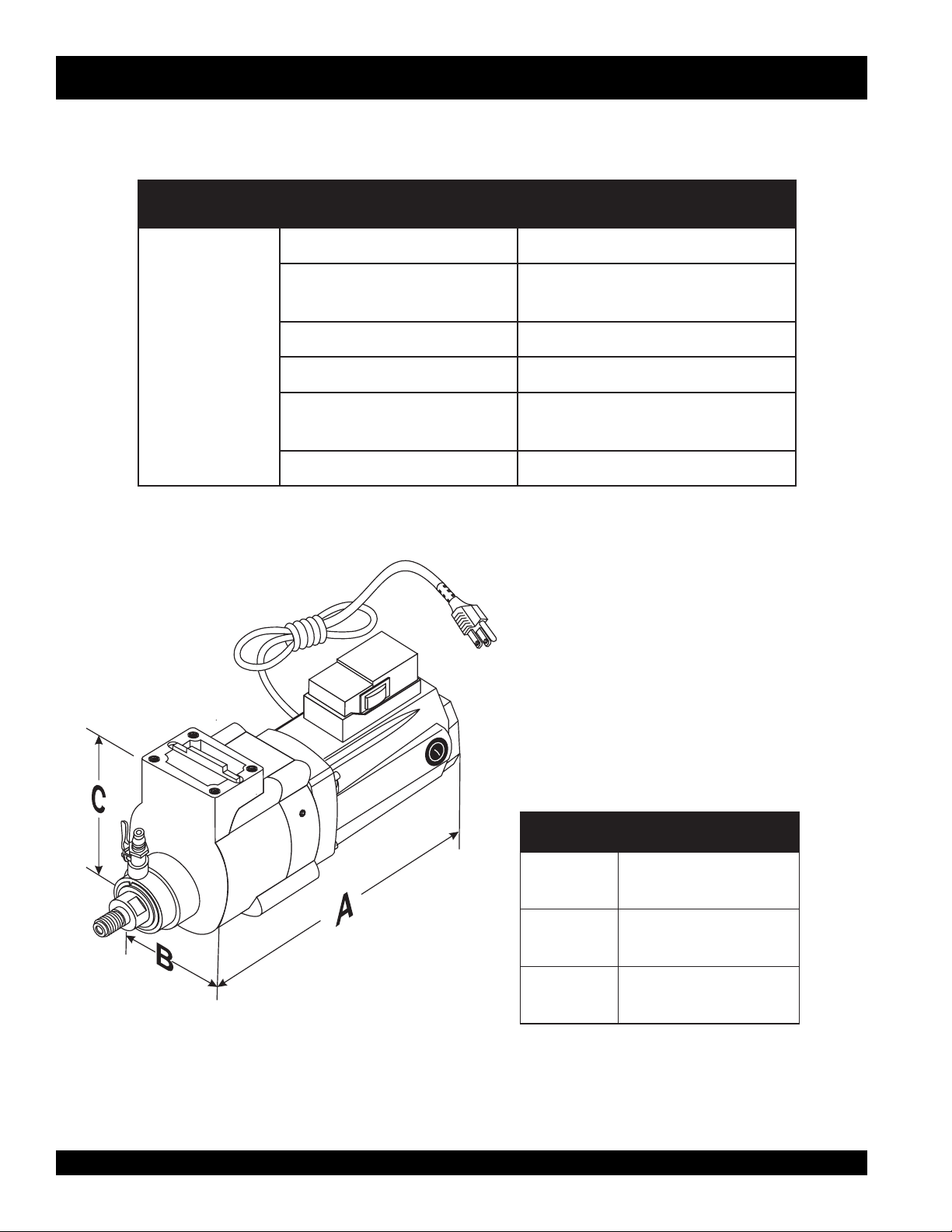
DM15A9C — SPECIFICATIONS/DIMENSIONS (MOTOR)
snoitacificepSrotoMcirtcelE.2elbaT
ledoMC9A51MD
rotoM
llirDeroC
rotoM
tnerruCspma51
sttaW008,1
maiDtiBllirDelbacilppA
rete
stiBllirDteWdradnatS
thgieWteNyrD).gK70.9(.sbl02
sehcni9~1
)mm6.822-4.52(
wol(MPR006@zH06,CAV021
)deepshgih(MPR0021,deeps
)htgneL(A
)htdiW(B
)thgieH(C
Figure 1. DM15A9C Electric Motor Dimensions
PAGE 12 —DM15A9C/CDM2CSA — OPERATION AND PARTS MANUAL — REV. #1 (11/09/05)
(
snoisnemiDC9A51MD.3elbaT
.ni57.81
)mm52.674(
.ni52.8
)mm55.902(
.ni00.6
)mm04.251
Page 13
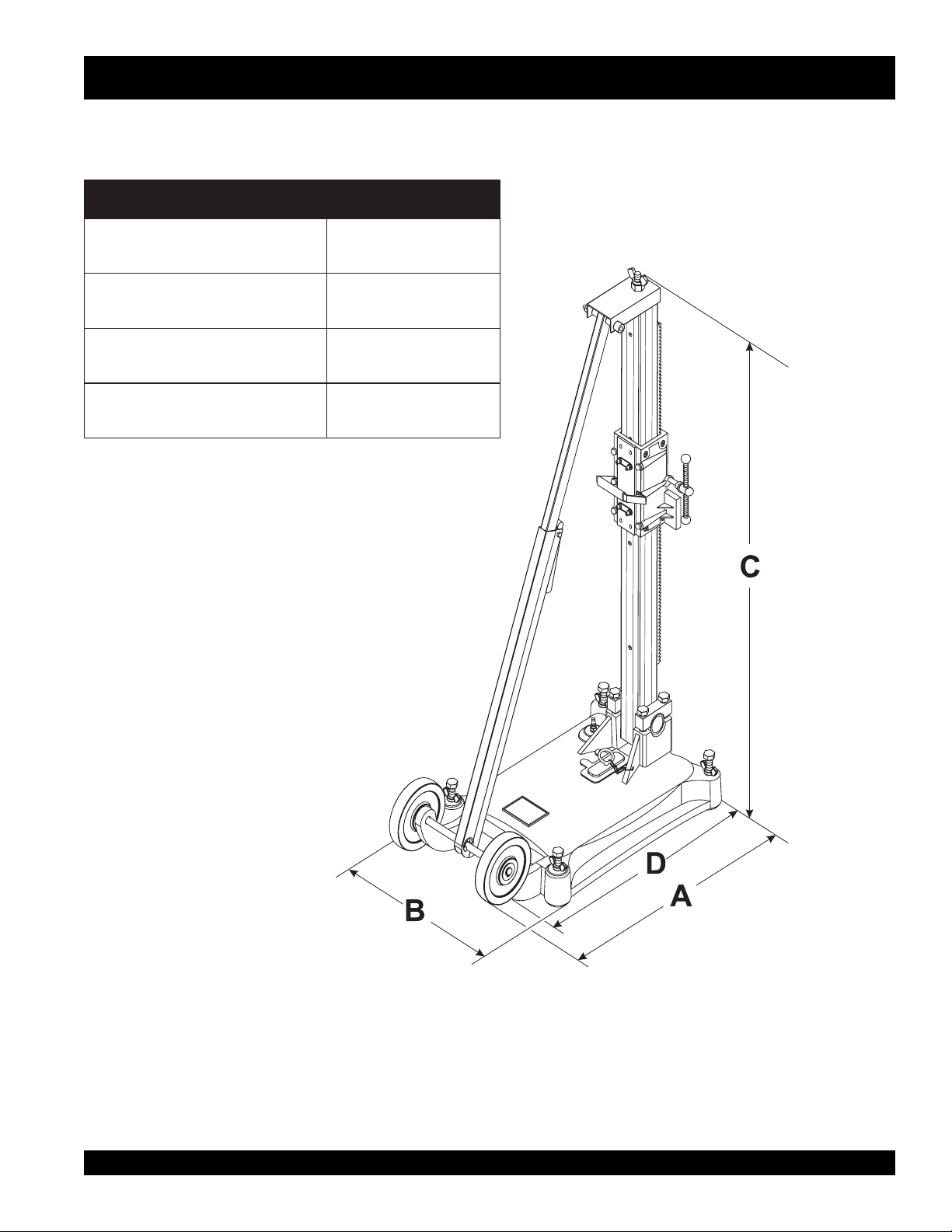
)htgneLlatoT(A.ni57.32
CDM2CSA — DIMENSIONS (DRILLING RIG)
snoisnemiDASC2MDC.4elbaT
)mm52.306(
)htdiW(B
)thgieH(C
)sleehWraeRoThtgneL(D
.ni52.21
)mm51.113(
.ni5.04
201(
)mm8
.ni81
)mm754(
Figure 2 CDM2CSA Drill Stand
DM15A9C/CDM2CSA — OPERATION AND PARTS MANUAL — REV. #1 (11/09/05) — PAGE 13
Page 14

DM15A9C/CDM2CSA— DRILL RIG COMPONENTS
Figure 3 illustrates the basic componets of the MQ CDM2CSA
Drill Rig. Shown below is breif explanation of each componet.
Figure 3. CDM2CSA Drill Rig Components
1. Leveling Screws – Use these screws (4) to level the
the drill rig.
2. Base – Supports the column rack and associated
components.
3. Wheels – 2 rear wheels have been provided for ease
of maneuverability. To move the drill rig grab hold of the
handle on the cradle assembly and tilt the unit slightly,
then pull or push.
4. Angle Rod – This is an adjustable rod. To shorten or
lengthen, squeeze and hold the rod release trigger. Set
angle rod to desired position, release trigger.
5. Adjustment Rod Cover Lock – This cover must be
secured to the column mast at all times when the unit
is in use. NEVER! use the drill rig with this cover
removed. The possibility exists of the column falling.
PAGE 14 —DM15A9C/CDM2CSA — OPERATION AND PARTS MANUAL — REV. #1 (11/09/05)
6. Cradle Assembly – This unit is responsible for the
7. Cradle Raise/Lower Handle – Use thishandle to raise
8. Vacuum Hose Fitting – Connect the output end of the
raising and lowering of the core drill and is placed onto
the colum rack. There is a tensioner knob located on
the side of the cradle that determines the ease at which
the cradle will move up and down along the rack.
Adjust the tension so that the cradle moves smoothly
and freely. Before placing core drill onto cradle, always
make sure the tension knob is securely tightened. This
will prevent the core drill from falling.
or lower the core drill.
vacuum pump hose to this fitting.
Page 15

DM15A9C/CDM2CSA — CORE DRILL MOTOR COMPONENTS
Figure 4 illustrates the basic componets of the MQ DM15A9C
Drill Rig. Shown below is breif explanation of each component.
Figure 4. DM15A9C Core Drill Motor
1. Speed Adjustment Knob – Use this knob to adjust
the speed of the electric motor. Turn knob counterclockwise to loosen. Push knob toward shaft end to
decrease motor speed. Pull knob back towards ON/
OFF switch to increase motor speed. Once knob is in
desired position, lock in place by turning fully clockwise.
2. AC Power Cord – Plug this 16 ft. (4.87 meters) power
cord into a 115 VAC grounded type receptacle. NEVER
remove the ground pin from the plug. This will defeat
the ground circuit and greatly increase the possibility
of electrical shock.
3. ON/OFF Rocker Switch– Press this rocker switch to
start and stop the electric motor.
4. Electric Motor Brush Covers (2) – Insert tip of a flat
blade screwdriver into slot on brush cover, turn counterclockwise and remove cover to gain access to brushes.
5. Drill Body –The electric motor and associated
components are contained inside the drill body.
6. Main Shaft – Attach core drill bit to this shaft. Main
shaft is 1-1/4"-7 (7 threads per inch) male. Shaft size
fits most core bits from 1-1/2" through 9" diameter.
7. Adapter Reducer – Multiquip offers (option) a reducing
adapter, 1-1/4"-7 female to 5/8"-11 male for bits smaller than 1-
1/2" diameter.
8. Core Drill Bit– Place bit onto main shaft and tighten
9. Wrenches – 3 wrenches are supplied with the
10. Water Shut-off Valve – Turn this valve downward to let
11. Water Tube/Adapter – Connect this tube/adapter to a
12. Core Drill Base/Woodruff key – Attach this base to
securely. Contact MQ sales department for the core
drill bit that best fits your application.
DM15A9C electric core drill motor. These wrenches
(17,19, 36 and 46 mm) are used to install and remove
the core drill bits.
water flow and up to stop.
water source, typically a garden hose.
the cradle assembly located on the column rack. Align
woodruff key with slot on base of cradle.
DM15A9C/CDM2CSA — OPERATION AND PARTS MANUAL — REV. #1 (11/09/05) — PAGE 15
Page 16

Before Starting:
DM15A9C/CDM2CSA — PRE-SETUP
CAUTION - Read Manual
Before attempting to operate
this core drill, and to avoid
serious injury to personnel,
always read and understand
operation manual. Failure to
read and understand operation
manual could result in serious
harm or even death!
DANGER - Flammable/Combustible Materials
NEVER operate the core drill in or around
flammable materials. The core drill emits
sparks. If contact is made between the
sparks and the flammable material,the
posibility exists of fire or explosion causing
damage to the equipment and severe bodily
harm even death!
Warning - Toxic Fumes
NEVER operate the core drill in a confined
or enclosed area structure that does not
provide ample
3. Place the drilling rig in an upright position on a firm flat
free flow of air
.
surface (Figure 5).
CDM-2CSA Drill Rig Assembly Instructions
Assemble the the CDM-2CSA Drilling Rig as follows:
1. Open the shipping container and place all associated
components on a suitable workbench that is clean and
free of debris.
2. Make sure all assembly components are accounted for
by checking them against items listed in Table 5. If any
components are missing, contact your nearest MQ
dealer.
4. Remove the wingnut located at the top of the column as
shown in Figure 6.
tsiLstraPylbmessA.5elbaT
metInoitpircseD.YTQ
1hcnerwmm91/711
2hcnerwmm631
3hcnerwmm641
4wercsmm31x2/1-14
5rehsawkcolhc
ni-8/54
Figure 5. Dril Rig (upright Position)
Figure 6. Wingnut Removal
PAGE 16 —DM15A9C/CDM2CSA — OPERATION AND PARTS MANUAL — REV. #1 (11/09/05)
Page 17

DM15A9C/CDM2CSA — PRE-SETUP
5. Locate the cradle assembly (Figure 7) and place it
directly over the column. Make sure the cradle handle is
located on the right side of the column if you are standing
at the back (wheels) of the drilling rig. It may be necessay
to loosen the cradle tension knob slightly to allow the
cradle to slip onto the column rack.
7. Once the cradle has been mounted onto the column
rack, align the top plate (Figure 9) on the adjustment bar
with the stud on the top of the column. It may be
necessary to squeeze the trigger release (Figure 8)
mechanism on the adjustment bar to to raise or lower the
adjustment bar.
Figure 9. Adjustment Bar Placement
Figure 7. Cradle Assembly
8. Re-install the wingnut that was removed in step 4.
6. Once the cradle assembly makes contact with the rack,
turn the cradle raise/lower handle (Figure 8) clockwise
so that the cradle moves in a downward position. Continue turning handle until the desired position has been
reached.
Figure 8. Cradle Raise/Lower Handle
9. The unit is now ready to be secured to the work surface.
Figure 10. Securing the Adjustment Bar
DM15A9C/CDM2CSA — OPERATION AND PARTS MANUAL — REV. #1 (11/09/05) — PAGE 17
Page 18

DM15A9C/CDM2CSA — PRE-SETUP
Securing the Drill Rig Assembly
Secure the Drilling Rig as follows:
DANGER - Drill Rig Tipping
DO NOT attempt to use this unit until it has been securely
anchored to a suitable surface. The possibility exists of
severe bodily harm and damage to the equipment if the
core drill bit becomes stuck or binds thus causing the unit
to tip over.
Slot
Vacuum Adapter
Pad
Figure 12. Vacuum Adapter Pad Insertion
This drilling rig can be secured by various methods. Please
read the next few paragraphs to determine which method
best suits your application.
Method 1 incorporates the use of a
vacuum pump will provide the necessary suction when used
in conjunction with the supplied rubber gasket seal.
1. Lay drilling rig in the down position so that access to base
plate is possible.
2. Make sure rubber gasket seal is placed evenly into base
plate groove as shown in Figure 11. For best results
apply a little water to the seal. Applying water to the seal
will make a tighter suction when the vacuum pump is
turned on. If seal is worn or damaged, replace with a new
one.
vacuum pump
Rubber Gasket
. The
5. On the vacuum pump there is a vacuum hose (Figure 13).
Connect the free end of the vacuum hose to vacuum line
hose fitting located on the baseplate.
6. Plug the power cord on the vacuum pump into a 120
VAC, 60 Hz power source. The unit will turn on immediately, there is no OFF/ON switch.
Figure 13. Vacuum Pump
7. Step on the base until it lowers and adheres to the work
Baseplate
8. Tighten the leveling screws (4) only enough to eliminate
Figure 11. Baseplate Rubber Gasket (Bottom View)
3. Return the drilling rig to its upright position.
4. Insert supplied vacuum adapter pad into slot on base of
drilling rig as shown in Figure 12.
PAGE 18 —DM15A9C/CDM2CSA — OPERATION AND PARTS MANUAL — REV. #1 (11/09/05)
DO NOT attempt to use this unit until
the vacuum guage reads a minimum
of 20 in. Hg . The possibility exists of
the gasket vacuum seal being broken
and the unit tipping over.
surface.
rocking. Over-tightening can lift the gasket off the ground
and release the vacuum.
CAUTION - VACUUM GAUGE READING
Page 19

DM15A9C/CDM2CSA — PRE-SETUP
Method 2 incorporates drilling a hole 1/2-inch in diameter
into the drill rig support surface (wall or floor), and inserting
an expansion type anchor.
1. Using a masonry bit, drill a hole approximately ½-inch in
diameter. When drilling the hole make sure it is approximately 200 mm away from center. See Figure 14. Make
the depth of the hole so that the desired anchor is flush
or just beneath the surface
Attaching the Core Bit to the Core Drill
Figure 14. Baseplate Drilling Alignment
1. Place the core bit and core drill motor on a suitable work-
2. Insert the anchor (Figure 15) into the1/2-inch hole that
was drilled into the surface. It may be necessary to
slighty tap the anchor into the hole. For best results, a
tight fit of the anchor is required. This will keep the anchor
from pulling out.
3. Align the slot on the baseplate with the 1/2-inch hole on
the surface.
4. Insert a 1/2-inch X 4.75 (not to exceed 4.75 inches) bolt
with a 1/2-inch washer through the baseplate slot and
screw it into the anchor.
5. Fully tighten the 1/2-inch bolt to secure the drill rig. If the
drill rig does not tighten down all the way, it may be
necessary to use additional 1/2-inch flat washers to fully
secure the drill rig.
bench or area that is free of clutter dirt and debris.
the core drill bit can be attached to the motor after the
motor has been secured to the drill rig,
2. Before installing the core bit, make sure that thepower cord
of the core drill is unplugged from the AC wall receptacle.
NEVER install the core bit on core drill that has power applied
to it.
3. Screw the core bit onto the main shaft of the core drill by
turning it clockwise by hand until tight (Figure 16).
4. Using the supplied wrenches continue to tighten the core bit.
When using the wrenches, apply pressure in the opposite
direction to fully tighten.
Figure 15. Baseplate (Expansion Anchor)
If desired
NOTE
DM15A9C/CDM2CSA — OPERATION AND PARTS MANUAL — REV. #1 (11/09/05) — PAGE 19
Different size wrenches may be
required depending on type of core
bit.
Figure 16. Attaching the Core Bit to the Core Drill
Page 20

DM15A9C/CDM2CSA — PRE-SETUP
Attaching the Core Drill Motor to the Cradle
1. There may be an aluminum adapter plate (Figure 17)
attached to the core drill motor. Remove this plate using
a 6 mm allen wrench before attempting to secure the drill
motor to the cradle. This adapter plate is intended to be
used on other MQ drill rig stands.
2. The core drill motor can be secured to the cradle (Figure 17)
by means of 4 retaing screws and lock washers. Use a
6 MM allen wrench to tighten the screws. Make sure to
align the woodruff key on the drill base with the slot on
the cradle.
3. The core drill motor is very heavy and with the added
weight of the drill bit makes it even heavier. When
mounting the drill motor to the cradle assembly,
use 2 people
.
always
Applying Power to the Core Drill
1. This core drill requires 115 VAC, 60 Hz power. Applying
power to the drill that is not specified will cause severe
damage to the core drill. Always read serial plate tag
before applying power to the core drill.
2. The power plug on this core drill is a 3-prong grounded
type plug. ALWAYS connect this plug to a 3-prong
grounded receptacle. NEVER plug this device into a 2prong type receptacle. This will defeat the ground circuit.
The use of a 3-prong to 2-prong adapter is strictly
prohibited.
To avoid accidental starting, ALWAYS
keep fingers away from the power OFF/
ON switch when applying power.
Warning - Accidental Starting
3. Connect the core drill's AC power cord to a 115 VAC wall
receptacle (Figure 19) that is protected by a 20 amp
circuit breaker. For best results connect the power cord
to a GFCI receptacle.
Figure 17. Attaching the Core Drill Motor to the Cradle
Connecting Water to the Core Drill
1. Attach the supplied water hose and garden hose fitting to the
core drill as shown in Figure 18. Be sure to place wormclamps on each end of the hose to prevent leaking.
Figure 19. Connecting the Power
Figure 18. Connecting the Water
PAGE 20 —DM15A9C/CDM2CSA — OPERATION AND PARTS MANUAL — REV. #1 (11/09/05)
Page 21

DM15A9C/CDM2CSA — OPERATION
Operation
1. Place the valve on the water source to the ON position, and
then turn the water valve on the core drill (Figure 20) to the
ON position (down). Verify that water is flowing smoothly
and evenly. Turn the valve clockwise to increse water flow
and counterclockwise to decrease water flow.
Figure 20. Water Valve (ON Position)
2. If water is not flowing, check all connections and correct the
problem. Water should be flowing at a rate of one or two
gallons per minutes.
Figure 21. Wall Drilling Application
3. Turn the core drill power ON/OFF switch to the ON position.
The drill bit should begin to rotate at the desired rpm setting.
4. Hold the cradle handle,then slightly loosen the cradle lock
knob and slowly rotate clockwise the raise/lower handle to
lower the bit into the work surface (Figures 21 and 22),
applying steady even pressure.
5. Water flow is adequate when the water and cuttings are
flushed in a circular pattern about 1/2-inch (12.7 mm) around
the bit.
6. To help reduce bit "walking", always use a light pressure to
start the hole and wait for the bit to penetrate the work surface
completely before increasing the pressure.
7. When the cut is complete, keep the drill motor ON and rotate
the raise lower handle counterclockwise to remove the bit.
NOTE
ALWAYS be on the lookout for
NOTE
exposed wiring or buried electrical
connections when drilling.
Danger - Drill Bit Cores
When removing the bit from the cut,
always keep the power on. This will
prevent bit from being stuck as the bit
is being raised. ALWAYS drill with
uniform pressure and keep the bit
straight. When drilling through steel
rebar, reduce the pressure to avoid
overloading the motor.
When drilling from high places, cores can often drop from
the drill bit. When drilling in high places make sure work
personnel and equipment below are clear of drilling area.
The possibility exists of a core falling on equipment causing
damage to the equipment or severe bodily harm even death!
to work personnel.
DM15A9C/CDM2CSA — OPERATION AND PARTS MANUAL — REV. #1 (11/09/05) — PAGE 21
Figure 22. Floor Drilling Application
Page 22

DM15A9C/CDM2CSA — SHUTDOWN
Shutdown
1. Place the power ON/OFF switch on the core drill motor in
the OFF position and unplug the power cord from the wall
receptacle or power source.
2. Allow a sufficient amount of time for the core drill bit to cool
before attempting to remove it from the core drill motor.
3. Using the wrenches as illustrated in Figure 4, remove the
core drill bit from the drill.
4. If desired remove the core drill motor from the cradle.Tighten
the cradle lock knob to prevent the cradle from falling off the
column rack.
5. If a vacuum pump was used to secure the unit, unplug its
power cord from the wall receptacle or power source. Open
the the vacuum release valve to release the vacuum
pressure.
5. If a an expandable anchor was used to secure the unit,
remove the securing bolt so that the unit can be moved.
6. Once the core drill has been cleaned, place the core drill
into its carrying case along with all associated hardware. Be
sure to wrap the power cord neatly into the carrying case.
This will extend the life of the cord.
7. Clean the drill bit with a mild cleaning solution, removing
dirt and foreign matter.
6. Store the drill rig and core drill motor out of the reach of
children, in a location that is moisture free.
PAGE 22 —DM15A9C/CDM2CSA — OPERATION AND PARTS MANUAL — REV. #1 (11/09/05)
Page 23

DM15A9C/CDM2CSA — MAINTENANCE
Maintenance
Clutch Adjustment
1. The DM15A9C electric motor is basically maintenance free.
However, it may become necessary at some time to adjust
the clutch.
2. Using a 5 mm allen wrench, remove the hex plug as shown
in Figure 23A to gain acess to the clutch adjustment hole.
3. Insert a small blade screwdriver (Figure 23B) into the access
hole so that it prevents the motor shaft from rotating fully.
4. Using the supplied wrenches (Figure 23B) rotate the motor
shaft counterclockwise about 15 degrees. The screwdriver
will keep the shaft from rotating fully.
Lubrication
1. Using a 5 mm allen wrench, remove the hex plug as shown
in Figure23A.
2. Visually inspect to see if grease is present. It may be
necessary to insert a small blade screw driver or similar
device into the filler hole to determine if the grease level is
low.
3. If the grease level is low, apply 1 shot of
grade N0.1. DO NOT over fill. See Figure 23C.
4. Reinstall hex plug and tighten securely.
Carbon Brushes
1. Using a flatblade screw driver unscrew the plastic cap as
shown in Figure 24 to gain acess to the carbon brushes.
There is a plastic cap on each side of the drill motor.
2. Periodically check the carbon brushes for signs of wear.
Typically replace brushes when the wear height is down to
0.2 inches (5mm). Using defective or worn brushes could
cause motor failure.
3. Replace worn or defective brushes with new ones. Keep
them clean so that they can slide freely within the brush
holder. Use only MQ recommended parts.
Figure 8. Wall Application
lithium base grease,
Figure 23. Clutch Adjustment/Lubrication
DM15A9C/CDM2CSA — OPERATION AND PARTS MANUAL — REV. #1 (11/09/05) — PAGE 23
Figure 24. Carbon Brush Replacement
Cleaning and Storage
1. Clean drill motor and drill rig with a mild soap and a damp
cloth removing dirt and foreign debris that might have
accumulated on the equipment during operation. DO NOT
use gasoline or harmful chemical as a cleaning agent some
of these chemicals are harmful to plastics.
2. Remove any dirt and dust from the motor vents
3. Store equipment in a clean dry location that is moisture free
out of the reach of children and unauthorized personnel.
Page 24

DM15A9C/CDM2CSA — TROUBLESHOOTING
GNITOOHSELBUORTLLIRDEROC.6ELBAT
MOTPMYS MELBORPELBISSOP NOITULOS
si.cte,enotsrorableetS
.?tibdnaerocneewtebthguac
.kcutssitiB
?tibdezalG .TIBecalpeR
?raber
?nrowsitiB .TIBecalpeR.noisarbarofTIBkcehcyletaidemmI
lamronniwolssignillirD
.noitarepo
?ecafrus
sahpittib,raewevissecxE
?knahshtiwhsulfemoceb
detanimatnocsiretawetsaW
gnittucsiLLIRD,pihcleetshtiw
?gnissimstnemgeS .TIBsserD.noisarbarofTIBkcehcyletaidemmI
.?cafrusTIBnodetisopedspihC
TIBnodehcrocseraspihcleetS
.FFOHCTIWSnrutetaidemmI
.tuotitfilotrennapsgnisusnoitceridhtobniTIBetatorotyrT
saosnoerusserpehttsujdA.retawretsawehtkcehcyletaidemmI
.ROTOMdaolrevootton
.erusserpdeefretawesaercnI.noisarbarofTIBkcehcyletaidemmI
.eriwahtiwTIBhsurBrosserD
.spihcleetsevomeR.noisarbarofTIBkcehcyletaidemmI
PAGE 24 —DM15A9C/CDM2CSA — OPERATION AND PARTS MANUAL — REV. #1 (11/09/05)
Page 25

NOTE PAGE
DM15A9C/CDM2CSA — OPERATION AND PARTS MANUAL — REV. #1 (11/09/05) — PAGE 25
Page 26

CORE DRILL — EXPLANATION OF CODE IN REMARKS COLUMN
The following section explains the different symbols and remarks
used in the Parts section of this manual. Use the help numbers
found on the back page of the manual if there are any questions.
The contents and part numbers listed in the parts section are
subject to change
guarantee the availibility of the parts listed.
Sample Parts List:
NO. PART NO. PART NAME QTY. REMARKS
1 12345 BOLT ....................... 1 .... INCLUDES ITEMS W/
2
*
2*12347 WASHER, 3/8 IN. .... 1....
3 12348 HOSE .................... A/R .. MAKE LOCALLY
4 12349 BEARING ................ 1 .... S/N 2345B AND ABOVE
NO. Column
Unique Symbols - All items with same unique symbol
, #, +, %, or >) in the number column belong to the same
(
*
assembly or kit, which is indicated by a note in the “Remarks”
column.
Duplicate Item Numbers - Duplicate numbers indicate
multiple part numbers are in effect for the same general item,
such as different size saw blade guards in use or a part that
has been updated on newer versions of the same machine.
NOTE
without notice
WASHER, 1/4 IN. ...........
When ordering a part that has more
than one item number listed, check
the remarks column for help in
determining the proper part to order.
. Multiquip does not
NOT SOLD SEPARATELY
MQ-45T ONLY
QTY. Column
Numbers Used - Item quantity can be indicated by a number,
a blank entry, or A/R.
A/R (As Required) is generally used for hoses or other parts
that are sold in bulk and cut to length.
A blank entry generally indicates that the item is not sold
separately. Other entries will be clarified in the “Remarks”
Column.
REMARKS Column
Some of the most common notes found in the “Remarks”
*
Column are listed below. Other additional notes needed to
describe the item can also be shown.
Assembly/Kit
symbol will be included when this item is purchased.
Indicated by:
“INCLUDES ITEMS W/(unique symbol)”
Serial Number Break
range where a particular part is used.
Indicated by:
“S/N XXXXX AND BELOW”
“S/N XXXX AND ABOVE”
“S/N XXXX TO S/N XXX”
Specific Model Number Use
only with the specific model number or model number variant
listed. It can also be used to show a part is NOT used on a
specific model or model number variant.
Indicated by:
“XXXXX ONLY”
“NOT USED ON XXXX”
- All items on the parts list with the same unique
- Used to list an effective serial number
- Indicates that the part is used
PART NO. Column
Numbers Used - Part numbers can be indicated by a number,
a blank entry, or TBD.
TBD (To Be Determined) is generally used to show a part that
has not been assigned a formal part number at time of
publication.
A blank entry generally indicates that the item is not sold
separately or is not sold by Multiquip. Other entries will be
clarified in the “Remarks” Column.
PAGE 26 —DM15A9C/CDM2CSA — OPERATION AND PARTS MANUAL — REV. #1 (11/09/05)
“Make/Obtain Locally”
purchased at any hardware shop or made out of available
items. Examples include battery cables, shims, and certain
washers and nuts.
“Not Sold Separately”
purchased as a separate item and is either part of an
assembly/kit that can be purchased, or is not available for
sale through Multiquip.
- Indicates that the part can be
- Indicates that an item cannot be
Page 27

DM15A9C/CDM2CSA— SUGGESTED SPARE PARTS
DM15A9C/CDM2CSA Core Drill and Drilling Rig
1 to 5 Units
Qty. ..... P/N ......................... Description
2 ......... CD290057 ............... CARBON BRUSH
2 ......... CD290062 ............... POWER CORD
2 ......... CD290065 ............... POWER SWITCH
DM15A9C/CDM2CSA — OPERATION AND PARTS MANUAL — REV. #1 (11/09/05) — PAGE 27
Page 28

NAMEPLATE AND DECALS
DM15A9C/CDM2CSA— NAMEPLATE AND DECALS
PAGE 28 —DM15A9C/CDM2CSA — OPERATION AND PARTS MANUAL — REV. #1 (11/09/05)
Page 29

DM15A9C/CDM2CSA— NAMEPLATE AND DECALS
NAMEPLATE AND DECALS
NO. PART NO. PART NAME QTY. REMARKS
1 DCL700 DECAL: CAUTION CLEAN WATER 1
2 CDL001 DECAL: CAUTION, OPERATION LIGHT 1
3 DCL704 DECAL: MODEL INFORMATION 1
4 CDL002 DECAL: INSTRUCTIONS 1
5 CDB001 DECAL: MQ LOGO 1
DM15A9C/CDM2CSA — OPERATION AND PARTS MANUAL — REV. #1 (11/09/05) — PAGE 29
Page 30

ELECTRIC MOTOR ASSY.
DM15A9C — ELECTRIC MOTOR ASSEMBLY
PAGE 30 —DM15A9C/CDM2CSA — OPERATION AND PARTS MANUAL — REV. #1 (11/09/05)
Page 31

DM15A9C — ELECTRIC MOTOR ASSEMBLY
ELECTRIC MOTOR ASSY.
NO. PART NO. PART NAME QTY. REMARKS
1 CD290001 GEAR CASE 1
2 CD290002 MAIN SHAFT 1
3 CD290003 SEAL, 34X48X8 MM 1
4 CD290004 BEARING, 6206LLU 1
5 CD290005 BEARING, 6206ZZ 1
6 CD290006 SNAP RING, R62 1
7 CD290007 SNAP RING, S30 1
8 CD2900081 METAL COLLAR 1
9 CD290009 METAL COLLAR 1
10 CD290010 FIRST GEAR 1
11 CD290011 METAL COLLAR 1
12 CD290012 SNAP RING, S29 1
13 CD290013 SHIFT RING 1
14 CD290014 SHIFT LEVER 1
15 CD290015 O-RING, 11X2.0 MM 1
16 CD290016 METAL COLLAR 1
17 CD290017 METAL 1
18 CD290018 SECOND GEAR 1
19 CD290019 METAL COLLAR 1
20 CD290020 SNAP RING, S22 1
21 CD290021 BEARING, 6202ZZ 1
22 CD290022 O-RING, 60X2.0 MM 1
23 CD290023 WATER SUPPLY COVER 1
24 CD290024 SNAP RING, IS63 1
25 CD290025 WATER COCK 1
26 CD290026 BEARING, 6201ZZ 1
27 CD290027 FIRST PINION 1
28 CD290028 WOODRUFF KEY, 5X5X12 MM 1
29 CD290029 SNAP RING, S15 1
30 CD290030 THIRD GEAR 1
31 CD290031 SECOND GEAR 1
32 CD290032 SPACER 1
33 CD290033 FORTH GEAR 1
34 CD290034 PLATE 2
35 CD290035 FRICTION PLATE 2
36 CD290036 METAL 1
37 CD290037 FIFTH GEAR 1
38 CD290038 DISK SPRING, 35.2X18.3X2.0 MM 4
39 CD290039 METAL COLLAR 1
40 CD290040 FINE U-NUT 1
41 CD290041 DIAPHRAGM 1
41A CD2900411 DIAPHRAGM SCREW, M8 60 4
41B CD2900412 DIAPHRAGM LOCK WASHER, M8 4
42 CD290042 SPEED CHANGE KNOB 1
43 CD290043 RUBBER WASHER 1
44 CD290044 PLUG, 1/8" 1
45 CD290045 BAFFLE 1
46 CD290046 BEARING, 6201LLU 1
47 CD290047 ARMATURE 1
48 CD290048 BEARING, 6200ZZ 1
49 CD290049 FILING RING, 6200 1
50 CD290050 O-RING 1
51 CD290051 FIELD 1
52 CD290052 FIELD SCREW, M5X85 MM 2
DM15A9C/CDM2CSA — OPERATION AND PARTS MANUAL — REV. #1 (11/09/05) — PAGE 31
Page 32

ELECTRIC MOTOR ASSY.
DM15A9C — ELECTRIC MOTOR ASSEMBLY
PAGE 32 —DM15A9C/CDM2CSA — OPERATION AND PARTS MANUAL — REV. #1 (11/09/05)
Page 33

DM15A9C — ELECTRIC MOTOR ASSEMBLY
ELECTRIC MOTOR ASSY.
NO. PART NO. PART NAME QTY. REMARKS
53 CD290053 WASHER,LOCK 5 MM 2
54 CD290054 WASHER, FLAT 5 MM 2
55 CD290055 MOTOR HOUSE 1
56 CD290056 BRUSH TUBE 2
56A CD5900561 BRUSH TUBE SCREW, M5X10 MM 2
57 CD290057 CARBON BRUSH 2
58 CD290058 BRUSH COVER 2
59 CD290059 SCREW, M6X45 MM 4
60 CD290060 WASHER, LOCK 6MM 4
61 CD290061 WASHER, FLAT 6MM 4
62 CD290062 ELECTRIC CABLE 1
63 CD290063 RUBBER TUB 1
64 CD290064 SWITCH BOX 1
65 CD290065 SWITCH 1
66 CD290066 SWITCH COVER 1
67 CD290067 SWITCH PLATE 1
68 CD290068 SWITCH SCREW, 1/8 X 1/4" 2
69 CD290069 LED INDICATOR 1
70 CD290070 CABLE 1
71 CD290071 EARTH CABLE 1
72 CD101569 HOSE CLAMP 2
73 CD101570 PLASTIC WATER HOSE, 4-INCH 1
74 CD101571 FITTING, BRASS BARB 3/4 X 3/8" 1
DM15A9C/CDM2CSA — OPERATION AND PARTS MANUAL — REV. #1 (11/09/05) — PAGE 33
Page 34

DRILLING RIG ASSY.
CDM2CSA — DRILLING RIG ASSEMBLY
PAGE 34 —DM15A9C/CDM2CSA — OPERATION AND PARTS MANUAL — REV. #1 (11/09/05)
Page 35

CDM2CSA — DRILLING RIG ASSEMBLY
DRILLING RIG ASSY.
NO. PART NO. PART NAME QTY. REMARKS
1 CD290072 BASE 1
2 CD290073 POLE TUBE 1
3 CD290074 POLE 1
4 CD290075 RACK 1
5 CD290076 POLE COVER 1
6 CD290077 FIXED PLATE 2
7 CD290078 WHEEL SHAFT 1
8 CD290097 WHEELS, 4" 2
9 CD290079 SCREW, M12X50 MM 1
10 CD290080 ANGLE ADJUSTMENT BRACKET 1
11 CD290081 ADJUST NUT, M12 1
12 CD290082 SCREW, M8X60 MM 1
13 CD290083 ANGLE ADJUST TUBE-2 1
14 CD290084 ANGLE ADJUST TUBE-1 1
15 CD290085 SCREW, M6X20 MM 1
16 CD290086 METAL COLLAR 1
17 CD290087 NUT 1
18 CD290088 SHIFTER 1
19 CD290089 SCREW, M6X35 MM 1
20 CD290090 NUT, M6 1
21 CD290091 SPRING 1
22 CD290092 SCREW, M6X55 MM 4
23 CD290093 VALVE 1
24 CD290094 AIR COVER 1
25 CD290095 SCREW, M12X40 MM 4
26 CD290096 CHAIN PIN 1
27 CD290098 SCREW, M12X100 MM 4
28 CD290099 NUT, M12 4
29 CD290100 GASKET 1
30 CD290101 WASHER 4
31 CD290102 S-RING, S1/2 2
32 CD290103 E-RING, E12 2
33 CD290104 O-RING, 3X53 MM 1
34 CD290105 NUT, M6 1
DM15A9C/CDM2CSA — OPERATION AND PARTS MANUAL — REV. #1 (11/09/05) — PAGE 35
Page 36

CRADLE ASSY.
CDM2CSA — CRADLE ASSEMBLY
PAGE 36 —DM15A9C/CDM2CSA — OPERATION AND PARTS MANUAL — REV. #1 (11/09/05)
Page 37

CDM2CSA — CRADLE ASSEMBLY
CRADLE ASSY.
NO. PART NO. PART NAME QTY. REMARKS
72 CD2704023 KEY, 10X10X105 MM 1
73 CD2704064 FEEDING HOUSE 1
74 CD2704065 BEARING, 6003ZZ 2
75 CD2704066 SNAP RING 2
76 CD2704067 FEED SHAFT 1
77 CD2704071 FEEDING HEAD 1
78 CD2704068 SCREW, M8X25 MM 1
79 CD2704069 KNOB 2
80 CD2704070 SPRING 2
81 CD2704072 FEEDING HANDLE 1
82 CD2704073 KNOB BOLT 1
83 CD2704074 SPRING 1
84 CD2704075 SET SCREW, M6X20 MM 6
85 CD2704076 HEX, NUT, M6 8
86 CD2704077 PLATE 4
87 CD2704078 FRI CTION PLATE-LONG 4
88 CD2704079 SCREW, 5/32X1/2" 8
89 CD2704080 FRICTION PLATE-SHORT 8
90 CD2704081 SCREW, M8X30 MM 4
91 CD2704082 FEEDING HOUSE COVER 1
92 CD2704083 SCREW, M8X20 MM 6
93 CD2704110 WASHER, LOCK M8 10
94 CD2704085 HANDLE 1
DM15A9C/CDM2CSA — OPERATION AND PARTS MANUAL — REV. #1 (11/09/05) — PAGE 37
Page 38

TOOLS
DM15A9C — TOOLS
PAGE 38 —DM15A9C/CDM2CSA — OPERATION AND PARTS MANUAL — REV. #1 (11/09/05)
Page 39

DM15A9C — TOOLS
TOOLS
NO. PART NO. PART NAME QTY. REMARKS
1 CD2704103 36 MM WRENCH 1
2 CD290008 46 MM WRENCH 1
3 CD290106 17/19 MM WRENCH 1
DM15A9C/CDM2CSA — OPERATION AND PARTS MANUAL — REV. #1 (11/09/05) — PAGE 39
Page 40

Effective: October 1, 2002
TERMS AND CONDITIONS OF SALE — PARTS
PAYMENT TERMS
Terms of payment for parts are net 10 days.
FREIGHT POLICY
All parts orders will be shipped collect or
prepaid with the charges added to the invoice.
All shipments are F.O.B. point of origin.
Multiquip’s responsibility ceases when a signed
manifest has been obtained from the carrier,
and any claim for shortage or damage must be
settled between the consignee and the carrier.
MINIMUM ORDER
The minimum charge for orders from Multiquip is $15.00 net. Customers will be asked
for instructions regarding handling of orders
not meeting this requirement.
RETURNED GOODS POLICY
Return shipments will be accepted and credit
will be allowed, subject to the following provisions:
1. A Returned Material Authorization must
be approved by Multiquip prior to shipment.
2. To obtain a Return Material Authorization,
a list must be provided to Multiquip Parts
Sales that defines item numbers, quantities, and descriptions of the items to be
returned.
a. The parts numbers and descriptions
must match the current parts price
list.
b. The list must be typed or computer
generated.
c. The list must state the reason(s) for
the return.
d. The list must reference the sales
order(s) or invoice(s) under which the
items were originally purchased.
e. The list must include the name and
phone number of the person requesting the RMA.
3. A copy of the Return Material Authorization must accompany the return shipment.
4. Freight is at the sender’s expense. All
parts must be returned freight prepaid to
Multiquip’s designated receiving point.
5. Parts must be in new and resalable con-
6. The following items are not returnable:
7. The sender will be notified of any material
8. Such material will be held for five working
9. Credit on returned parts will be issued at
10. In cases where an item is accepted, for
11. Credit issued will be applied to future
PRICING AND REBATES
Prices are subject to change without prior
notice. Price changes are effective on a specific date and all orders received on or after that
date will be billed at the revised price. Rebates
for price declines and added charges for price
increases will not be made for stock on hand
at the time of any price change.
Multiquip reserves the right to quote and sell
dition, in the original Multiquip package (if
any), and with Multiquip part numbers
clearly marked.
a. Obsolete parts. (If an item is in the
price book and shows as being replaced by another item, it is obsolete.)
b. Any parts with a limited shelf life
(such as gaskets, seals, “O” rings,
and other rubber parts) that were purchased more than six months prior to
the return date.
c. Any line item with an extended dealer
net price of less than $5.00.
d. Special order items.
e. Electrical components.
f. Paint, chemicals, and lubricants.
g. Decals and paper products.
h. Items purchased in kits.
received that is not acceptable.
days from notification, pending instructions. If a reply is not received within five
days, the material will be returned to the
sender at his expense.
dealer net price at time of the original
purchase, less a 15% restocking charge.
which the original purchase document
can not be determined, the price will be
based on the list price that was effective
twelve months prior to the RMA date.
purchases only.
direct to Government agencies, and to Origi-
nal Equipment Manufacturer accounts who
use our products as integral parts of their own
products.
SPECIAL EXPEDITING SERVICE
A $35.00 surcharge will be added to the invoice
for special handling including bus shipments,
insured parcel post or in cases where Multiquip
must personally deliver the parts to the carrier.
LIMITATIONS OF SELLER’S LIABILITY
Multiquip shall not be liable hereunder for
damages in excess of the purchase price of the
item with respect to which damages are
claimed, and in no event shall Multiquip be
liable for loss of profit or good will or for any
other special, consequential or incidental dam-
ages.
LIMITATION OF WARRANTIES
No warranties, express or implied, are made
in connection with the sale of parts or trade
accessories nor as to any engine not manufac-
tured by Multiquip. Such warranties made in
connection with the sale of new, complete units
are made exclusively by a statement of war-
ranty packaged with such units, and Multiquip
neither assumes nor authorizes any person to
assume for it any other obligation or liability
whatever in connection with the sale of its
products. Apart from such written statement of
warranty, there are no warranties, express,
implied or statutory, which extend beyond the
description of the products on the face hereof.
PAGE 40 —DM15A9C/CDM2CSA — OPERATION AND PARTS MANUAL — REV. #1 (11/09/05)
Page 41

NOTE PAGE
DM15A9C/CDM2CSA — OPERATION AND PARTS MANUAL — REV. #1 (11/09/05) — PAGE 41
Page 42

OPERATION AND PARTS MANUAL
HERE'S HOW TO GET HELP
PLEASE HAVE THE MODEL AND SERIAL
NUMBER
ON-HAND
WHEN CALLING
UNITED STATES
Multiquip Corporate Office MQ Parts Department
18910 Wilmington Ave. Tel. (800) 421-1244 800-427-1244 Fax: 800-672-7877
Carson, CA 90746 Fax (800) 537-3927 310-537-3700 Fax: 310-637-3284
Contact: mq@multiquip.com
Mayco Parts Warranty Department
800-306-2926 Fax: 800-672-7877 800-421-1244, Ext. 279 Fax: 310-537-1173
310-537-3700 Fax: 310-637-3284 310-537-3700, Ext. 279
Service Department Technial Assistance
800-421-1244 Fax: 310-537-4259 800-478-1244 Fax: 310-631-5032
310-537-3700
MEXICO UNITED KINGDOM
MQ Cipsa Multiquip (UK) Limited Head Office
Carr. Fed. Mexico-Puebla KM 126.5 Tel: (52) 222-225-9900 Hanover Mill, Fitzroy Street, Tel: 0161 339 2223
Momoxpan, Cholula, Puebla 72760 Mexico Fax: (52) 222-285-0420 Ashton-under-Lyne, Fax: 0161 339 3226
Contact: pmastretta@cipsa.com.mx Lancashire OL7 0TL
Contact: sales@multiquip.co.uk
CANADA BRAZIL
Multiquip Multiquip
4110 Industriel Boul. Tel: (450) 625-2244 Av. Evandro Lins e Silva, 840 - grupo 505 Tel: 011-55-21-3433-9055
Laval, Quebec, Canada H7L 6V3 Fax: (450) 625-8664 Barra de Tijuca - Rio de Janeiro Fax: 011-55-21-3433-9055
Contact: jmartin@multiquip.com Contact: cnavarro@multiquip.com.br, srentes@multiquip.com.br
© COPYRIGHT 2005, MULTIQUIP INC.
Multiquip Inc, the MQ logo are registered trademarks of Multiquip Inc. and may not be used, reproduced, or altered without written permission. All other trademarks are the
property of their respective owners and used with permission.
This manual MUST accompany the equipment at all times. This manual is considered a permanent part of the equipment and should remain with the unit if resold.
The information and specifications included in this publication were in effect at the time of approval for printing. Illustrations are based on the
CDM2CSA Drilling Rig.
Multiquip Inc. reserves the right to discontinue or change specifications, design or the information published in this publication at any time without notice and without
incurring any obligations.
Illustrations, descriptions, references and technical data contained in this manual are for guidance only and may not be considered as binding.
DM15A9C Core Drill and
Your Local Dealer is:
 Loading...