

Page 1

PARTS MANUAL
CUTTER 1 CE SERIES
MODEL CD6CE13H18
CONCRETE/ASPHALT SAW
(HONDA GX390 GASOLINE ENGINE)
Revision #1 (12/20/07)
To find the latest revision of this
publication, visit our website at:
www.stowmfg.com
THIS MANUAL MUST ACCOMPANY THE EQUIPMENT AT ALL TIMES.
P/N 35454
Page 2
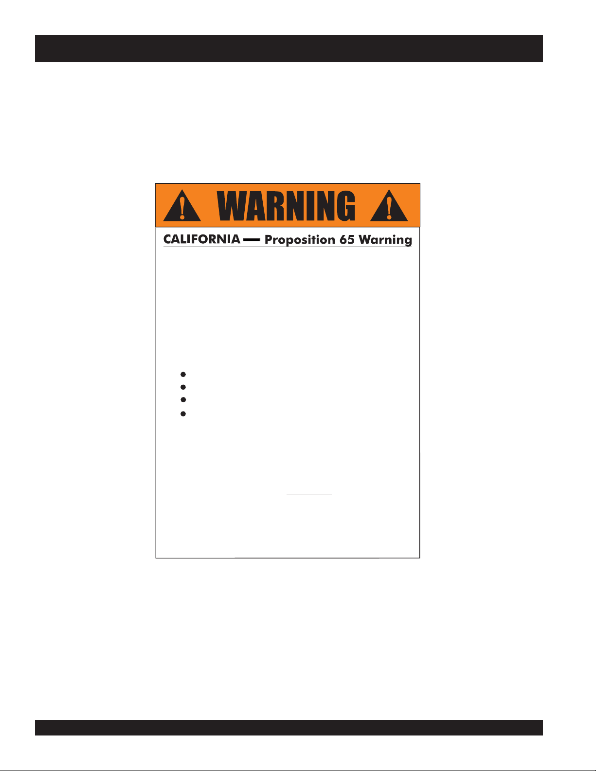
STOW CUTTER 1 CE SAW — PROPOSITION 65 WARNING
Engine exhaust and some of
its constituents, and some dust created
by power sanding, sawing, grinding,
drillingandotherconstructionactivities
contains chemicals known to the State
of California to cause cancer, birth
defects and other reproductive harm.
Some examples of these chemicals are:
Leadfromlead-basedpaints.
Crystallinesilicafrombricks.
Cementandothermasonryproducts.
Arsenicandchromiumfrom chemically
treatedlumber.
Your risk from these exposures varies,
dependingonhowoftenyoudothistype
of work. To reduce your exposure to
these chemicals: work in aALWAYS
well ventilated area, and work with
approved safety equipment, such as
dust masks that are specially designed
to filter out microscopic particles.
PAGE 2 — STOW CUTTER 1 CE — PARTS MANUAL — REV. #1 (12/20/07)
Page 3
STOW CUTTER 1 CE SAW — SILICOSIS/RESPIRATORY WARNINGS
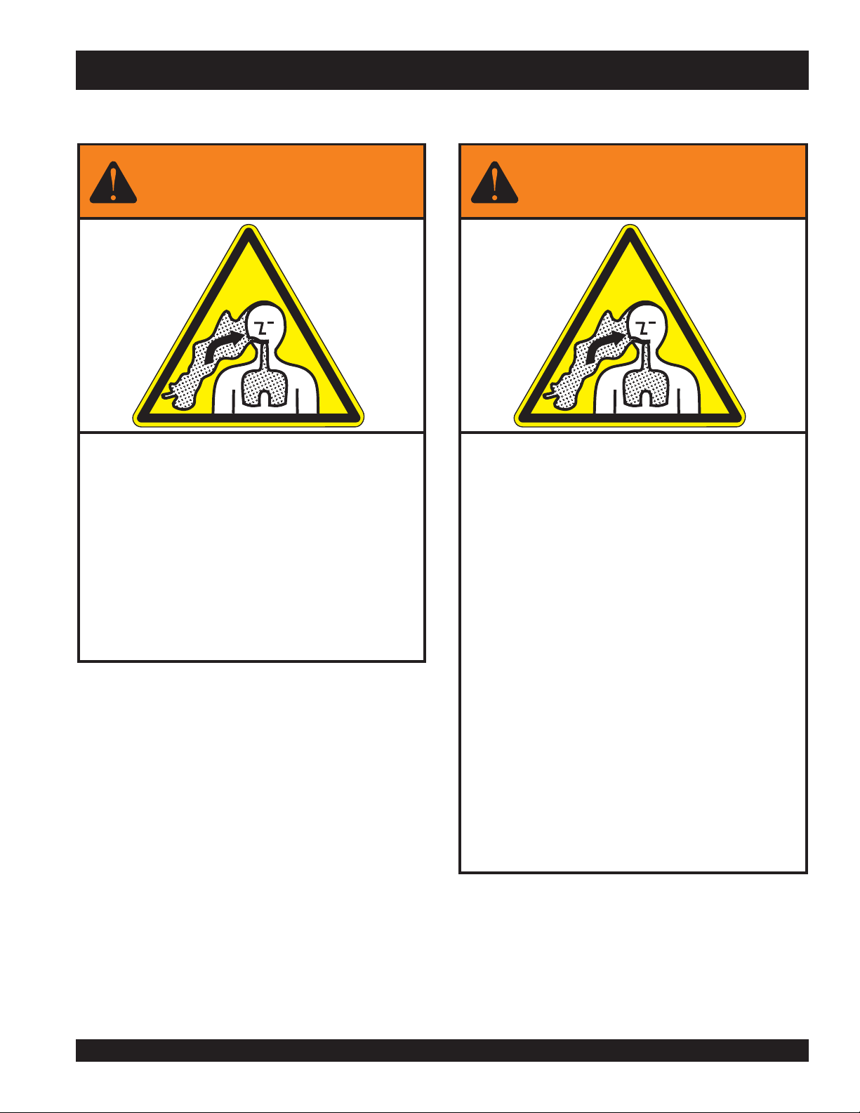
WARNING
SILICOSIS WARNING RESPIRATORY HAZARDS
Grinding/cutting/drilling of masonry, concrete, metal and
other materials with silica in their composition may give
off dust or mists containing crystalline silica. Silica is a
basic component of sand, quartz, brick clay, granite and
numerous other minerals and rocks. Repeated and/or
substantial inhalation of airborne crystalline silica can
cause serious or fatal respiratory diseases, including
silicosis. In addition, California and some other
authorities have listed respirable crystalline silica as a
substance known to cause cancer. When cutting such
materials, always follow the respiratory precautions
mentioned above.
WARNING
Grinding/cutting/drilling of masonry, concrete, metal and
other materials can generate dust, mists and fumes
containing chemicals known to cause serious or fatal
injury or illness, such as respiratory disease, cancer,
birth defects or other reproductive harm. If you are
unfamiliar with the risks associated with the particular
process and/or material being cut or the composition of
the tool being used, review the material safety data
sheet and/or consult your employer, the material
manufacturer/supplier, governmental agencies such as
OSHA and NIOSH and other sources on hazardous
materials. California and some other authorities, for
instance, have published lists of substances known to
cause cancer, reproductive toxicity, or other harmful
effects.
Control dust, mist and fumes at the source where
possible. In this regard use good work practices and
follow the recommendations of the manufacturers or
suppliers, OSHA/NIOSH, and occupational and trade
associations. Water should be used for dust
suppression when wet cutting is feasible. When the
hazards from inhalation of dust, mists and fumes cannot
be eliminated, the operator and any bystanders should
always wear a respirator approved by NIOSH/MSHA for
the materials being used.
STOW CUTTER 1 CE — PARTS MANUAL — REV. #1 (12/20/07) — PAGE 3
Page 4
STOW CUTTER 1 CE SAW — TABLE OF CONTENTS
STOW CUTTER 1 CE SAW
Model CD6CE13H18
Proposition 65 Warning ............................................. 2
Silicosis/Respiratory Warnings .................................. 3
Table Of Contents ..................................................... 4
Parts Ordering........................................................... 5
Explanation of Codes in Remarks Column ............... 6
Suggested Spare Parts ............................................. 7
Decals .................................................................... 8-9
Engine, Belts And Pulleys .................................. 10-11
Undercarriage Assembly ................................... 12-13
Blade Assembly & Water System ....................... 14-15
Pointer Assembly ............................................... 16-17
Water Tank (Option) ........................................... 18-19
HONDA GX390K1QWT2/
GX390U1QWT2 ENGINES
Air Cleaner Assembly......................................... 20-21
Camshaft Assembly ...........................................22-23
Carburetor Assembly ......................................... 24-25
Control Assembly ............................................... 26-27
Crankcase Cover Assembly ............................... 28-29
Crankshaft Assembly .........................................30-31
Cylinder Barrel Assembly ................................... 32-33
Cylinder Head Assembly .................................... 34-35
Fan Cover Assembly .......................................... 36-37
Flywheel Assembly ............................................ 38-39
Fuel Tank Assembly ........................................... 40-41
Ignition Coil Assembly ........................................ 42-43
Muffler Assembly ............................................... 44-45
Piston Assembly ................................................. 46-47
Recoil Starter Assembly ..................................... 48-49
Labels ................................................................ 50-51
NOTE
Specifications and
part numbers are
subject to change
without notice.
Terms and Conditions of Sale — Parts ................... 52
PAGE 4 — STOW CUTTER 1 CE — PARTS MANUAL — REV. #1 (12/20/07)
Page 5
PARTS ORDERING PROCEDURES
When ordering parts,
please supply the following information:
❒❒
❒ Dealer account number
❒❒
❒❒
❒ Dealer name and address
❒❒
❒❒
❒ Shipping address (if different than billing address)
❒❒
❒❒
❒ Return fax number
❒❒
❒❒
❒ Applicable model number
❒❒
❒❒
❒ Quantity, part number and description of each part
❒❒
❒❒
❒ Specify preferred method of shipment:
❒❒
✓ FedEx or UPS Ground
✓ FedEx or UPS Second Day or Third Day
✓ FedEx or UPS Next Day
✓ Federal Express Priority One
✓ DHL
✓ Truck
Note: Unless otherwise indicated by customer, all
orders are treated as “Standard Orders”, and will
ship within 24 hours. We will make every effort to
ship “Air Shipments” the same day that the order
is received, if prior to 2PM west coast time. “Stock
Orders” must be so noted on fax or web forms.
Here’s how to get help...
Please have the model and serial number
on hand when calling.
STOW MAIN OFFICE
18910 Wilmington Ave. 800-421-1244
FAX:
Carson, CA 90746
Email: stow@stowmfg.com
Internet: www.stowmfg.com
SALES DEPARTMENT
310-661-4242 Fax: 310-604-9237
877-289-7869 (877-BUY-STOW)
PARTS DEPARTMENT
800-427-1244
310-537-3700
SERVICE DEPARTMENT
800-478-1244
310-537-3700
TECHNICAL ASSISTANCE
800-478-1244
WARRANTY DEPARTMENT
800-421-1244,
310-537-3700,
EXT.
EXT.
279
279
310-537-3927
FAX:
800-672-7877
FAX:
310-637-3284
FAX:
310-537-4259
FAX:
310-631-5032
FAX:
310-537-1173
Place Your Parts Order Via Web or Fax
For Even More Savings!
(Domestic USA Dealers Only)
Extra Discounts!
All parts orders which include complete part numbers and
are received by our automated web parts order system, or
by fax qualify for the following extra discounts:
Ordered Standard Stock orders
via orders ($750 list and above)
Fax 3% 10%
Web 5% 10%
Special freight allowances
when you order 10 or more
line items via Web or Fax!**
FedEx Ground Service
No other allowances on freight shipped by any other
carrier.
**Common nuts, bolts and washers (all items under $1.00
list price) do not count towards the 10+ line items.
NOTE: DISCOUNTS ARE SUBJECT TO CHANGE
at no charge for freight
STOW CONSTRUCTION EQUIPMENTSTOW CONSTRUCTION EQUIPMENT
STOW CONSTRUCTION EQUIPMENT
STOW CONSTRUCTION EQUIPMENTSTOW CONSTRUCTION EQUIPMENT
A DIVISION OF MULTIQUIP INC.
POST OFFICE BOX 6254 CARSON, CA 90749
888-252-STOW [888-252-7869] 310-537-3700
FAX: 310-537-1986 FAX: 800-556-1986
E-MAIL: stow@multiquip.com INTERNET: www.stowmfg.com
STOW CUTTER 1 CE — PARTS MANUAL — REV. #1 (12/20/07) — PAGE 5
Direct TOLL-FREE access
to our Parts Department:
Toll-free nationwide — 800-427-1244
Toll-free FAX — 800-6-PARTS-7
(800/672-7877)
Page 6

EXPLANATION OF CODE IN REMARKS COLUMN
The following section explains the different symbols and
remarks used in the Parts section of this manual. Use the help
numbers found on the back page of the manual if there are any
questions.
The contents and part numbers listed in the parts section are
subject to change
guarantee the availibility of the parts listed.
Sample Parts List:
NO. PART NO. PART NAME QTY. REMARKS
1 12345 BOLT ...................... 1 ......INCLUDES ITEMS W/
2
*
2*12347 WASHER, 3/8 IN. ... 1 ......
3 12348 HOSE ................... A/R .... MAKE LOCALLY
4 12349 BEARING ............... 1 ......S/N 2345B AND ABOVE
NO. Column
Unique Symbols - All items with same unique symbol
(*, #, +, %, or >) in the number column belong to the same
assembly or kit, which is indicated by a note in the “Remarks”
column.
Duplicate Item Numbers - Duplicate numbers indicate
multiple part numbers are in effect for the same general
item, such as different size saw blade guards in use or a
part that has been updated on newer versions of the same
machine.
When ordering a part that has more than one
item number listed, check the remarks column
for help in determining the proper part to order.
without notice
WASHER, 1/4 IN. .............
. Multiquip does not
NOT SOLD SEPARATELY
MQ-45T ONLY
*
QTY. Column
Numbers Used - Item quantity can be indicated by a
number, a blank entry, or A/R.
A/R (As Required) is generally used for hoses or other parts
that are sold in bulk and cut to length.
A blank entry generally indicates that the item is not sold
separately. Other entries will be clarified in the “Remarks”
Column.
REMARKS Column
Some of the most common notes found in the “Remarks”
Column are listed below. Other additional notes needed to
describe the item can also be shown.
Assembly/Kit
unique symbol will be included when this item is purchased.
Indicated by:
“INCLUDES ITEMS W/(unique symbol)”
Serial Number Break
number range where a particular part is used.
Indicated by:
“S/N XXXXX AND BELOW”
“S/N XXXX AND ABOVE”
“S/N XXXX TO S/N XXX”
Specific Model Number Use
used only with the specific model number or model number
variant listed. It can also be used to show a part is NOT
used on a specific model or model number variant.
Indicated by:
“XXXXX ONLY”
“NOT USED ON XXXX”
- All items on the parts list with the same
- Used to list an effective serial
- Indicates that the part is
PART NO. Column
Numbers Used - Part numbers can be indicated by a
number, a blank entry, or TBD.
TBD (To Be Determined) is generally used to show a part
that has not been assigned a formal part number at time of
publication.
A blank entry generally indicates that the item is not sold
separately or is not sold by Multiquip. Other entries will be
clarified in the “Remarks” Column.
PAGE 6 — STOW CUTTER 1 CE — PARTS MANUAL — REV. #1 (12/20/07)
“Make/Obtain Locally”
purchased at any hardware shop or made out of available
items. Examples include battery cables, shims, and certain
washers and nuts.
“Not Sold Separately”
purchased as a separate item and is either part of an
assembly/kit that can be purchased, or is not available for
sale through Multiquip.
- Indicates that the part can be
- Indicates that an item cannot be
Page 7

STOW CUTTER 1 CE SAW — SUGGESTED SPARE PARTS
SUGGESTED SPARE PARTS
STOW CUTTER 1 CE SAW CONCRETE/ASPHALT SAW
1 TO 3 UNITS WITH HONDA 13 HP GX390K1QWT2/GX390U1QWT2
ENGINES
1 to 3 Units
Qty. ......P/N ........................... Description
3 20478 ................... HAND GRIP
4 2621 ..................... GREASE ZERK, SPINDLE BEARING
4 1162 A .................. CAP, GREASE ZERK
3 13249 ................... BELT (3VX315) 13HP HONDA
3 16779-006 ............ BELT (3VX300) 5HP ELECTRIC MOTOR
3 9807956846 ......... SPARK PLUG, BPR6ES, NKG
1
1
1
2 17210ZE3010 ...... AIR CLEANER ELEMENT
1
1
2 28086001 ............. 8" REAR WHEEL ( GAS MODEL)
2 26221001 ............. 4" FRONT WHEEL
1 29013001 ............. 1-1/2" BOX WRENCH
17620ZH7023 ...... TANK CAP, BLACK, (S/N 3605677 AND BELOW)
17620Z0T305 ...... TANK CAP, CHROME PLATED, (S/N 3605678 AND ABOVE)
◊◊
◊
17620Z0T305 ...... TANK CAP, CHROME PLATED
◊◊
28462ZV7003 ...... ROPE, RECOIL STARTER
◊◊
◊
28462ZE3W01 .... ROPE, RECOIL STARTER
◊◊
STOW CUTTER 1 CE — PARTS MANUAL — REV. #1 (12/20/07) — PAGE 7
Page 8
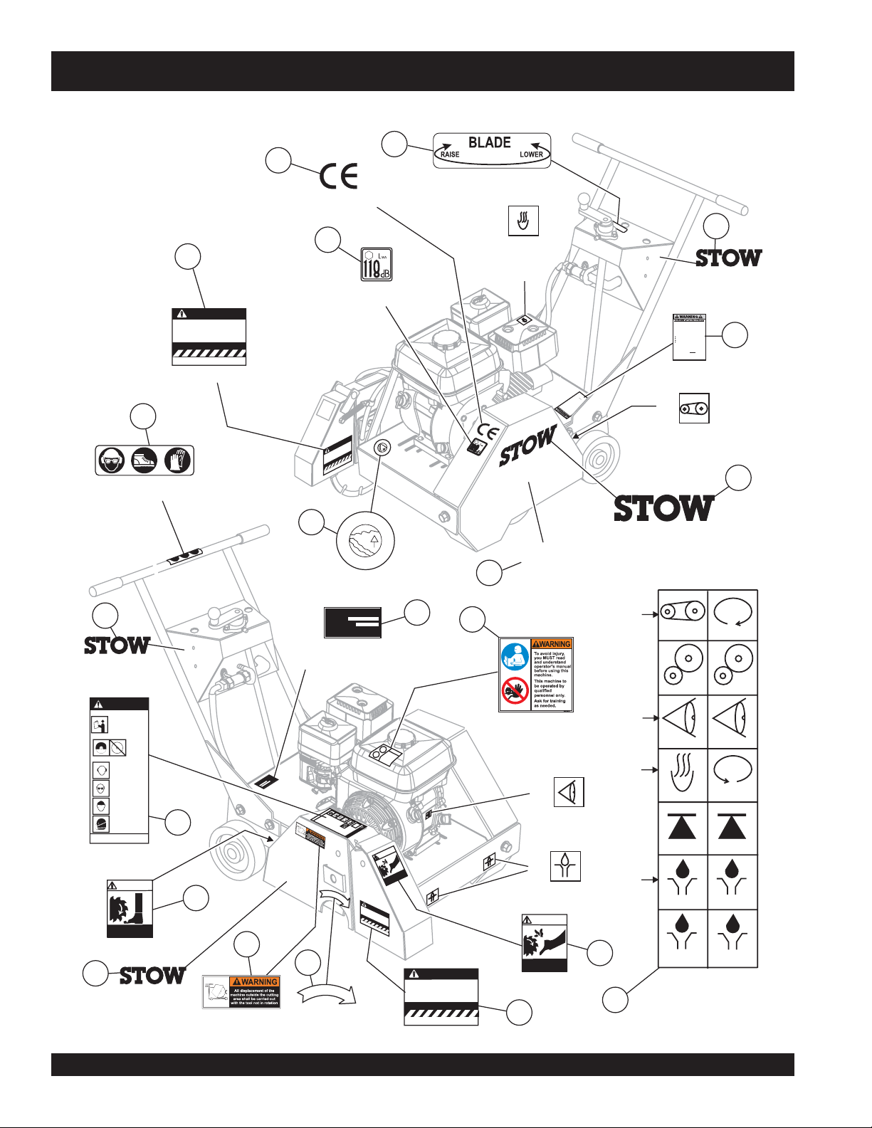
DECALS
CUTTER
1
CUTTER
1
STOW CUTTER 1 CE SAW — DECALS
17
15
P/N 35158
P/N 11092
11
When Larger Blade and Guard
is Installed, Belt Drive MUST
Be Changed to Proper Size.
See Owners Manual.
FAILURETO COMPLY WITH THE C CAH
JADV EEEAV EEAOIEJGGVCBVVZ
S.M.I.MASONRY AND CONCRETE
SAWMANUFACTURER’S INSTITUTE
P/N 23330-001
6
P/N 36099 (ISO Blue)
5
P/N 22972-003
6.00 LG
WARNING
TOPREVENT SERIOUS INJURY
DONOT OPERATE SAW
WITHOUTPROPER TRAINING
&FULL UNDERSTANDING
OFTHE OWNERS MANUAL
WHENOPERATING THIS MACHINE
KEEPALL
GUARDSIN
PLACE
ALWAYSWEAR SAFETYAPPROVED
HEARING
PROTECTION
EYEOR FACE
PROTECTION
HEAD
PROTECTION
RESPIRATOR
MASONRYAND CONCRETE
SMI
SAWMANUFACTURING INSTITUTE
7
P/N 22122-001
WARNING!
8
KEEP FEET
CLEAR
P/N 25250-001
5
P/N 22972-003
6.00 LG
CAUTION
P/N 25867
14
16
P/N 35167
rd
ua
G
d
T
n
S
CAUTION
a
U
e
.
M
d
e
la
iz
B
rive
S
r
r
D
e
e
lt
rg
p
e
ro
B
La
,
P
AH
n
l.
d
C
e
a
to
h
C
u
lle
d
n
a
t
W
e
a
HE
VZ
s
T
g
V
M
n
In
B
a
C
ITH
rs
is
h
GV
C
YW
ne
JG
e
PL
w
IE
M
B
O
O
O
A
C
e
e
EE
TO
S
ETE
E
AV
R
R
E
UTE
C
N
ILU
EE
TIT
O
S
FA
C
V
IN
D
’S
JAD
ER
YAN
R
R
N
TU
O
C
A
AS
UF
.I.M
AN
M
S.M
SAW
D
W
3
O
P
C
O
A
T
P/N 13118
MODEL
SERIAL NO.
CONTACT MULTIQUIP
SERVICE DEPARTMENT
SERIALNO.
MODEL
N
S
a
s
M
f
s
I
a
e
r
d
f
g
h
h
t
e
tf
a
N
t
h
r
e
b
s
s
s
f
a
f
a
i
w
t
n
h
r
N
e
p
d
w
e
b
f
s
i
g
o
e
b
f
a
a
t
r
t
r
d
t
e
N
b
h
f
N
a
s
g
e
t
h
s
a
e
i
s
s
n
f
t
s
s
f
e
f
a
a
p
a
r
t
e
b
e
h
b
t
r
b
h
r
s
s
N
N
d
e
d
a
i
f
e
f
g
s
s
g
s
f
h
f
a
s
f
a
a
h
t
a
r
e
e
t
b
e
e
r
s
t
r
N
h
t
d
d
i
h
s
a
f
f
s
g
s
g
f
f
a
h
s
n
c
w
h
a
t
b
s
p
t
h
e
e
c
w
N
a
b
t
e
WARNING
r
c
h
c
b
t
i
e
N
d
R
o
h
e
s
c
s
f
t
s
f
e
t
)
g
f
a
s
y
f
a
s
1
h
a
f
r
f
e
a
g
b
9
h
w
a
r
r
u
s
b
t
e
b
e
iz
d
w
4
r
i
s
f
c
t
io
d
h
i
i
n
f
n
s
t
g
f
a
a
t
w
w
i
o
t
O
R
T
A
T
I
O
N
W
h
e
n
i
s
L
I
n
a
s
B
t
a
e
l
l
e
C
S
h
a
e
n
e
g
O
w
FA
n
I
L
U
J
A
R
D
E
V
TO
E
E
E
S
.
M
.
I
S
.
A
M
W
A
S
M
O
A
N
U
F
10
A
T
T
I
O
O
N
R
P/N 25491
O
P
W
D
E
R
C
O
A
T
E
D
E
R
D
E
WARNING!
D
N
A
H
P
R
E
A
E
E
K
L
C
C
A
U
r
g
T
e
IO
r
B
d
l
N
,
a
B
d
e
e
l
e
t
a
d
D
n
d
t
r
o
i
e
v
G
r
e
P
s
u
r
M
M
a
o
r
p
U
a
d
e
n
S
C
r
O
u
T
S
M
a
AV
P
i
l
z
.
L
E
e
YW
E
.
A
I
O
T
I
H
E
J
T
G
H
G
E
V
N
C
C
R
C
B
YA
V
A
A
V
H
N
C
Z
D
T
U
C
R
O
E
N
R
C
’
S
R
E
I
N
T
S
E
T
I
T
U
T
E
9
S
CAUTION
When Larger Blade and Guard
is Installed, Belt Drive MUST
Be Changed to Proper Size.
See Owners Manual.
FAILURETO COMPLY WITH THE C CAH
JADV EEEAV EEAOIEJGGVCBVVZ
S.M.I.MASONRY AND CONCRETE
SAWMANUFACTURER’S INSTITUTE
P/N 23330-001
5
1
“HOT”
C
d
e
.
n
s
s
e
g
l
i
c
s
h
i
t
ha
t
e
i
c
r
aA
w
a
u
yd
s
p
l
n
l
k
i
o
,
c
r
a
t
i
t
i
k
p
n
c
e
r
e
e
wo
o
e
r
p
c
,
p
y
u
m
wo
t
s
s
s
d
s
p
e
o
s
i
n
o
i
e
i
r
S
r
r
u
a
p
h
c
a
i
t
q
,
va
t
e
ex
o
a
a
s
d
WAY
e
r
h
y
y
e
r
L
l
t
t
u
l
r
u
a
e
a
s
u
f
yo
c
s
yo
a
i
:
d
.
n
s
o
s
e
s
e
m
l
e
t
p
t
t
e
a
c
f
a
d
c
l
c
u
i
e
ex
u
i
t
ch
d
d
e
wo
n
m
e
o
s
o
m
e
e
r
e
v
h
o
r
:
h
f
n
ch
t
yp
l
e
Tor
.
r
o
r
.
.
m
e
s
n
a
m
g
k
u
s
k
o
r
m
o
i
s
n
.
c
e
l
i
r
r
.
s
i
f
h
s
r
a
m
h
a
r
d
a
t
t
t
e
wo
c
r
o
k
h
b
n
n
i
i
r
m
b
e
i
f
s
e
t
i
r
a
e
m
m
o
p
r
m
a
e
ch
v
p
e
o
t
,b
e
s
i
r
u
r
h
r
t
l
d
d
e
S
f
d
t
u
i
e
c
ch
,
n
e
d
t
a
o
e
c
i
u
a
g
s
e
e
c
Yo
d
h
v
t
n
i
d
a
c
n
i
s
t
l
i
i
n
a
a
i
t
d
o
b
e
a
e
c
n
d
-
s
r
c
e
o
h
r
t
t
t
f
e
a
n
d
p
t
e
t
i
a
n
s
f
o
a
e
e
n
n
n
r
r
e
i
e
r
e
o
s
l
r
o
g
l
w
l
i
A
u
r
c
m
s
t
o
a
,
a
t
e
t
m
e
e
c
e
n
l
g
c
s
s
h
o
u
C
k
t
p
n
r
r
m
y
u
i
f
t
r
o
s
o
d
o
m
l
s
w
d
t
C
s
a
a
e
a
d
n
a
c
s
e
n
o
i
a
m
ex
i
a
c
L
,
o
m
e
n
r
d
g
s
r
s
e
e
n
t
m
n
o
d
i
h
a
f
c
o
t
i
ch
n
d
l
e
o
S
a
f
n
a
s
,
d
e
a
t
n
C
s
i
n
d
s
t
s
a
a
f
n
u
t
r
g
e
o
a
n
e
n
u
h
o
i
t
w
l
i
c
l
t
o
i
ex
r
s
d
n
o
e
c
byp
n
s
i
t
i
g
n
E
CUTTER
1
CUTTER
1
P/N 23653-001
P/N 35137
B
“CHECK”
D
“LUBRICATION”
WARNING!
KEEP HANDS
CLEAR
P/N 25249-001
11
m
t
u
o
r
k
e
s
t
l
a
i
f
m
o
t
t
s
ov
u
r
d
p
p
l
a
e
w
P/N 22972-004
A
B
C
D
12
13
5
P/N 22972-003
6.00 LG
Engine exhaust and some of
itsconstituents,andsome dustcreated
bypower sanding,sawing, grinding,
drillingandotherconstructionactivities
containschemicalsknown to the State
of California to cause cancer,birth
defectsand other reproductiveharm.
Someexamplesofthese chemicalsare:
Leadfromlead-basedpaints.
Crystallinesilicafrombricks.
Cementandothermasonryproducts.
Arsenicandchromiumfromchemically
treatedlumber.
Yourriskfrom these exposures varies,
dependingonhowoftenyoudothis type
ofwork.To reduceyour exposureto
thesechemicals: workin aALWAYS
well ventilated area, and work with
approvedsafety equipment,such as
dustmasksthat arespecially designed
tofilterout microscopicparticles.
P/N 20525
A
“BELT DRIVE”
7.00 LG
BELT DRIVE
GEAR DRIVE
CHECK
LUBRICATION
LUBRICATION
DECAL SHEET
INTL STDS ISO
CLOCKWISE
GEAR DRIVE
COUNTER
HOT
CLOCKWISE
LIFTING POINTLIFTING POINT
LUBRICATION
LUBRICATION
P/N 11246
2
4
CHECK
PAGE 8 — STOW CUTTER 1 CE — PARTS MANUAL — REV. #1 (12/20/07)
Page 9

STOW CUTTER 1 CE SAW — DECALS
DECALS
NO. PART NO. PART NAME QTY. REMARKS
1 35137 DECAL, WARNING, READ MANUAL .. 1 .......... SAFETY ITEM
2 20525 DECAL, PROP 65 WARNING ............. 1 .......... SAFETY ITEM
3 13118 DECAL, POWDER COATED 1
4 22972-004 DECAL, STOW 7.00 LG 1
5 23653-001 DECAL, CUTTER 1 1
6 36099 DECAL, ISO SAFETY GEAR ............. 1 .......... SAFETY ITEM
7 22122-001 DECAL, WARNING .............................. 1 .......... SAFETY ITEM
8 25250-001 DECAL, WARNING FEET ................... 1 .......... SAFETY ITEM
9 22972-003 DECAL, STOW 6.00 LG 3
10 25491 DECAL, ROTATION CW ...................... 1 .......... SAFETY ITEM
10 25678 DECAL, ROTATION CCW .................... 1 .......... SAFETY ITEM
11 23330-001 DECAL, CAUTION "BELT DRIVE" ...... 2 .......... SAFETY ITEM
12 25249-001 DECAL, WARNING HANDS ................ 1 .......... SAFETY ITEM
13 11246 DECAL SHEET, INTL STDS ............... 1 .......... SAFETY ITEM
14 25867 DECAL, WARNING CE BLADE ........... 1 .......... SAFETY ITEM
15 11092 DECAL, CE 1
16 35167 DECAL, SOUND POWER ................... 1 .......... SAFETY ITEM
17 35158 DECAL, BLADE RAISE/LOWER ........ 1 .......... SAFETY ITEM
18 SERIAL NUMBER PLATE ................... 1 .......... CONTACT PARTS DEPT.
19 35440 MANUAL, CUTTER 1 CE OPER. 1
20 35454 MANUAL, CUTTER 1 CE PARTS 1
STOW CUTTER 1 CE — PARTS MANUAL — REV. #1 (12/20/07) — PAGE 9
Page 10
STOW CUTTER 1 CE SAW — ENGINE, BELTS AND PULLEYS
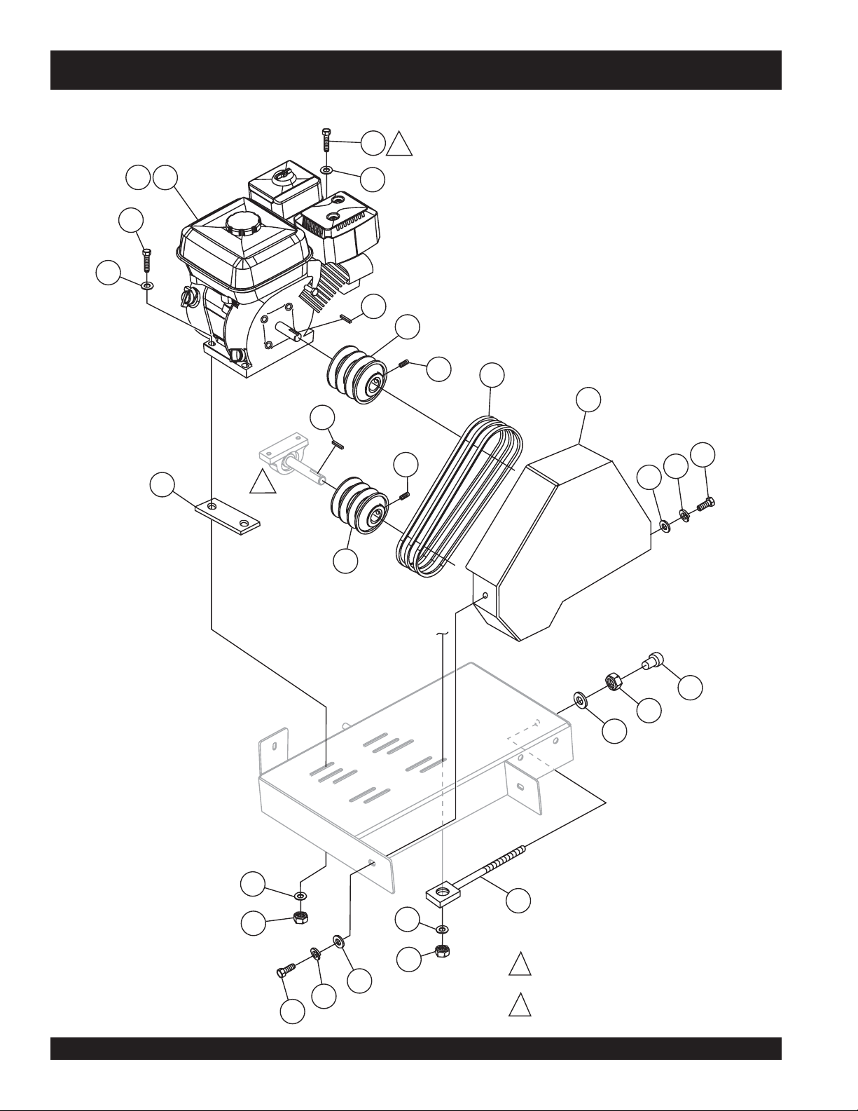
ENGINE, BELTS AND PULLEYS
1
2
3
4
3
2
4
7
8
12
9
10
13
17
9
1
19
14
15
11
18
19
16
4
6
5
4
5
BLADE SPINDLE ASSEMBLY.
1
19
15
14
PAGE 10 — STOW CUTTER 1 CE — PARTS MANUAL — REV. #1 (12/20/07)
BELT TENSIONER MOUNT
2
BOLT. (TO ITEM 6.)
Page 11

STOW CUTTER 1 CE SAW— ENGINE, BELTS AND PULLEYS
ENGINE, BELTS AND PULLEYS
NO. PART NO. PART NAME QTY. REMARKS
1 15103 ENGINE 13 HP HONDA RED 1
2 9152 KEY, 1/4 X 1-3/4 1
3 0669 A SCREW. HHCS 5/16-18 x 2-1/4" 4
4 19470 WASHER, FLAT USS 5/16" 8
5 5283 NUT, 5/16 - 18 LOCK 4
6 23811-352 BELT TENSIONER 2
7 6059 B SQUARE KEY, 1/4 X 2 1
8 23665-001 PULLEY, ENGINE 1
9 25354 SCREW, SHS 1/4 - 20 X 1/2 ALLOY 4
10 13249 BELT, 3VX315 3
11 23665-009 PULLEY, SPINDLE 1
12 27044-001 SPACER 2
13 26105-351 BELT GUARD, 13HP YELLOW............. 1 ......... SAFETY ITEM
14 0202 SCREW, 5/16 - 18 X 1 2
15 0161 C WASHER, LOCK 5/16 2
16 10136 WASHER, FLAT 3/8 1
17 10779-011 CAP 2
18 10133 NUT, 3/8 - 16 1
19 0300 B WASHER, FLAT SAE 5/16 2
STOW CUTTER 1 CE — PARTS MANUAL — REV. #1 (12/20/07) — PAGE 11
Page 12
UNDERCARRIAGE ASSY.
STOW CUTTER 1 CE SAW — UNDERCARRIAGE ASSY.
PAGE 12 — STOW CUTTER 1 CE — PARTS MANUAL — REV. #1 (12/20/07)
Page 13

STOW CUTTER 1 CE SAW — UNDERCARRIAGE ASSY.
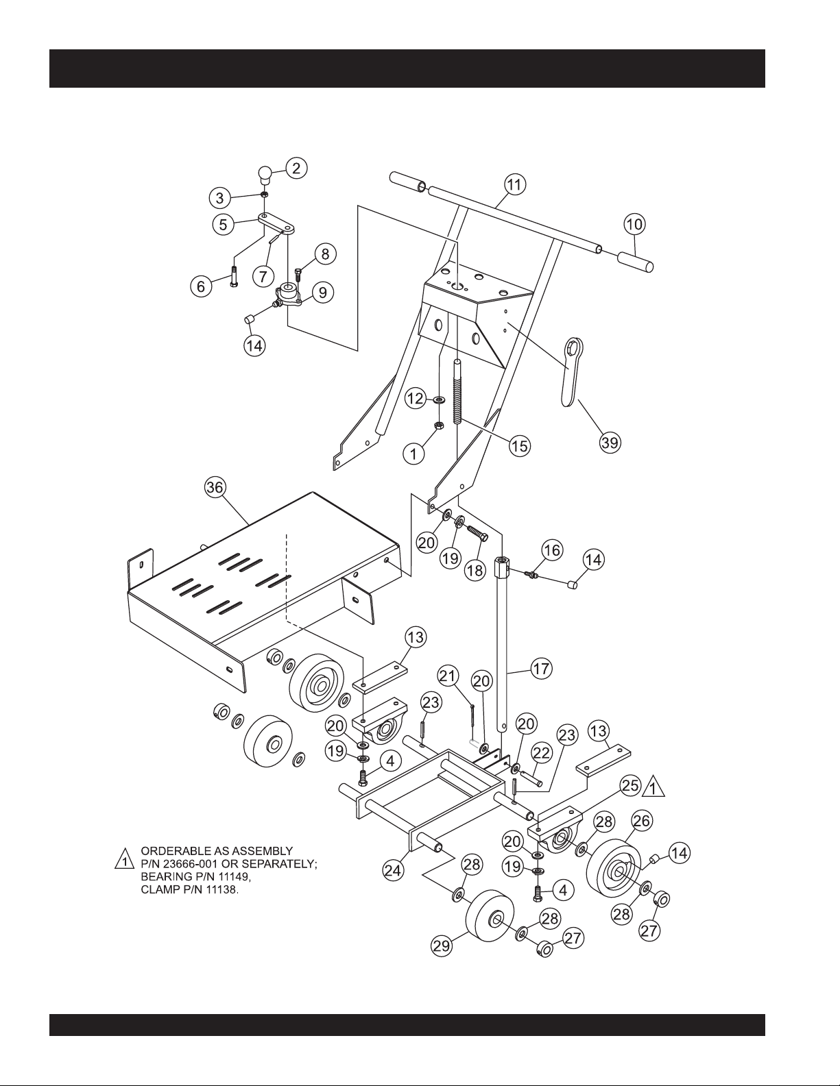
UNDERCARRIAGE ASSY.
NO. PART NO. PART NAME QTY. REMARKS
1 05283 NUT, NYLOC 5/16 - 18 2
2 4403 KNOB 1
3 1876 NUT, HEX 3/8-16 1
4 1284 SCREW, HHC 3/8-16 X 1-1/2 4
5 28808-002 CRANK ARM 1
6 1121 SCREW, HHC 3/8-16 X 2-3/4 1
7 4568 ROLL PIN 3/16 X 1 1
8 2623 SCREW, HHC 5/16-18 X 1-1/4 2
9 23284-001 FLANGE BEARING 1
10 15081 HAND GRIP 2
11 26126-354 HANDLE 1
12 0300 B FLATWASHER 5/16 2
13 25677 SPACER, REAR AXLE BEARING 2
14 1162 A CAP, GREASE ZERK 4
15 26137-002 ACME SCREW 1
16 2621 ZERK, GREASE STR 1/4 - 28 1
17 29408-352 JACK ARM (SUPPORT TUBE) 1
18 0205 SCREW, HHC 3/8 - 16 X 1 4
19 0166 A LOCKWASHER, 3/8 8
20 10136 FLATWASHER 3/8 10
21 6014 B COTTER PIN 3/32 X 1 1
22 08326-019 PIN 3/8 X 2-5/16 1
23 07402-024 ROLL PIN 1/8 X 1-1/2 2
24 26120-352 WHEEL BASE ASSEMBLY 1
25 23666-001 CLAMP & BEARING ASSEMBLY ... 2 .......... INCLUDES ITEMS W/#
25A# 11138 CLAMP ASSEMBLY 2
25B# 11149 BEARING 2
26 28086-001 REAR WHEEL, 8X2 2
27 26133-001 LOCKING COLLAR 4
28 8151 FLATWASHER, 3/4 6
29 26121-001 FRONT WHEEL 2
30 35131 CLAMP, DESTACO MODEL 609 ..... 2 .......... SAFETY ITEM
31 0131 A SCREW, HHC 1/4 - 20 X 3/4 8
32 0202 SCREW, HHC 5/16 - 18 X 1 2
33 0106 NUT, HEX JAM 5/16 - 18 2
34 0948 WASHER, FLAT SAE 1/4 8
35 10024 NUT, NYLOC 1/4 - 20 8
36 26112-354 FRAME 1
37 35127 SWITCH, ENGINE ON/OFF ............ 1 .......... SAFETY ITEM
38 35134 WIRE, ENGINE OFF SWITCH........ 1 .......... SAFETY ITEM
39 29013-001 1-1/2" BOX WRENCH 1
STOW CUTTER 1 CE — PARTS MANUAL — REV. #1 (12/20/07) — PAGE 13
Page 14
STOW CUTTER 1 CE SAW — BLADE ASSEMBLY & WATER SYSTEM
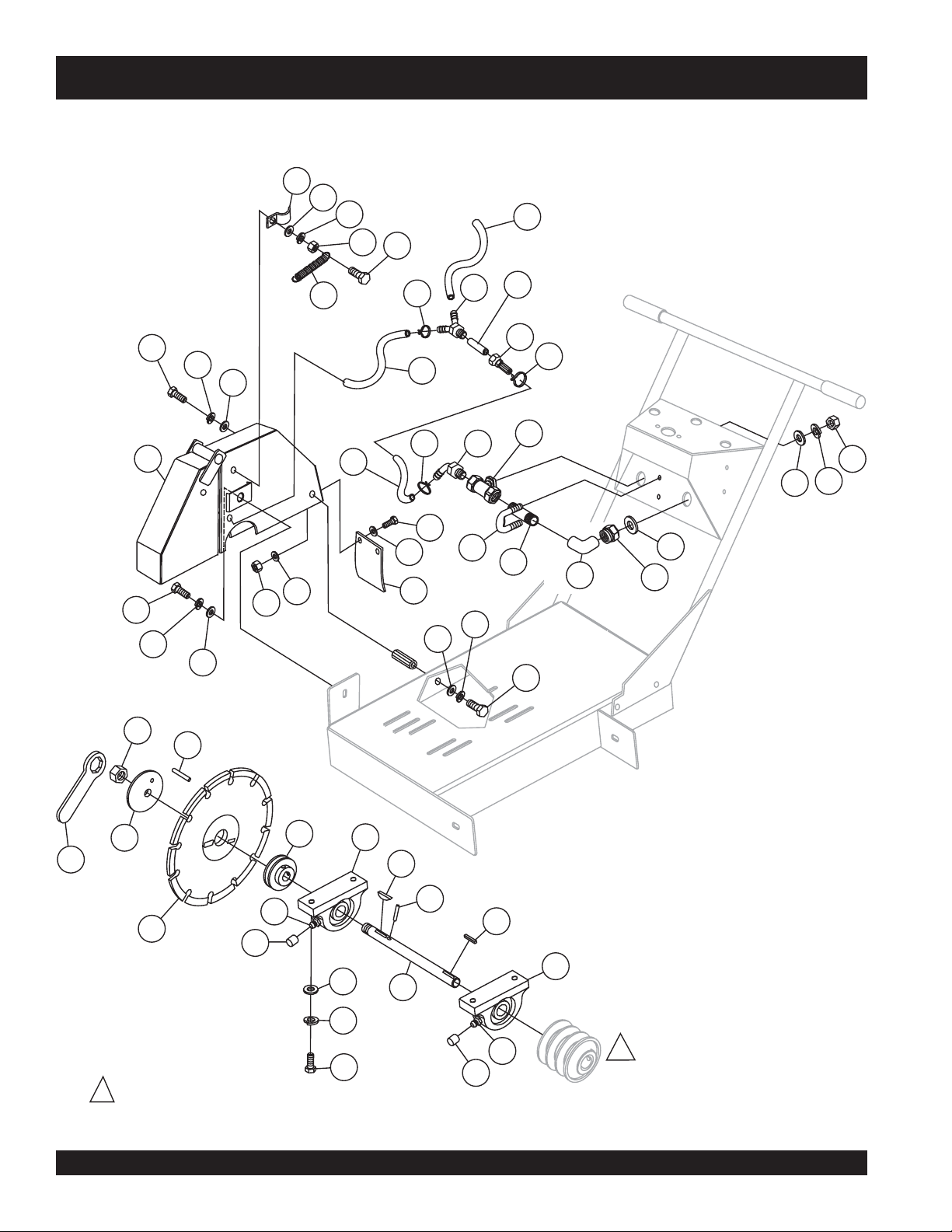
BLADE ASSEMBLY & WATER SYSTEM
1
2
7
3
4
5
19
18
20
2590.8mm
20
355.6mm
/14”
/102”
28
29
28
6
26
30
26
25
25
24
355.6mm
660.4mm
23
/14”
/26”
17
16
20
16
8
10
9
4
3
2
21
2
12
11
13
15
14
22
26
25
28
16
31
19
PULLEY ASSEMBLY.
1
SEE PAGE 30.
32
35
36
30
27
39
37
35
33
38
26
40
34
PAGE 14 — STOW CUTTER 1 CE — PARTS MANUAL — REV. #1 (12/20/07)
37
1
Page 15

STOW CUTTER 1 CE SAW — BLADE ASSEMBLY & WATER SYSTEM
BLADE ASSEMBLY & WATER SYSTEM
NO. PART NO. PART NAME QTY. REMARKS
1 22129-001 CLAMP,PIPE STRAP 3/8 2
2 0948 FLATWASHER, 1/4 6
3 0181B LOCK WASHER 1/4 4
4 0949 HEX NUT 1/4 - 20 4
5 0424 SCREW, HHC 1/4 - 20 X 1 4
6 29406-353 BLADE GUARD 18" YELLOW ......... 1 .......... SAFETY ITEM
7 18626-001 SPRING, TENSION 2
8 23255-011 HOSE, BRAIDED 1/2 X 26" 1
9 23566-001 FITTING, 1/2MP X 1/2 BARB 1
10 35122-402 VALVE, GLOBE 1/2 FNPT BRASS 1
11 11708 NIPPLE 1/2MP X 2.5 1
12 16378-005 U-BOLT 1/4-20 X 1 X 1-1/2 1
13 23252-002 ELBOW 1/2 1
14 15544 CONNECTOR, GARDEN HOSE 1
15 13336-001 WASHER, RUBBER 1
16 29013-001 WRENCH, BOX END 1-1/2 1
17 24778-001 FITTING, BRASS 1/2 BARB X 3/4 1
18 14233-004 FITTING, PLASTIC Y 3/8 BARB 1
19 BLADE, DIAMOND BACK .............. 1 .......... CONTACT PARTS DEPT.
20 60021 .............. HOSE, 1.25 FT. ............................... 2 .......... SOLD PER FOOT
21 0131 A SCREW, HHC 1/4 - 20 X 3/4 2
22 28729-005 GUARD, SPLASH ........................... 1 .......... SAFETY ITEM
23 10930 FENDER WASHER 1/4 X 1-1/4 2
24 10024 NUT, NYLOC 1/4 - 20 2
25 10136 WASHER, FLAT 3/8 3
26 0166 A WASHER, LOCK 3/8 3
27 2621 FITTING, GREASE ZERK 2
28 0205 SCREW, HHC 3/8 - 16 X 1 3
29 06922-003 NUT, HEX JAM L.H. 1 - 1/4 1
30 24894-024 DOWEL PIN 3/8 X 1-1/2 NO PLT 2
31 26928-004 FLANGE, OUTER 1
32 28811-001 FLANGE, INNER 1
33 4001 FLATWASHER 4
34 1284 SCREW, HHC 3/8 - 16 X 1-1/2 4
35 3200 BEARING 2
36 0125 WOODRUFF KEY 1/4 X 1 1
37 1162 A CAP, GREASE ZERK 2
38 26135-002 SHAFT, SPINDLE 1
39 6059 B KEY, SQUARE 1/4 X 2 1
STOW CUTTER 1 CE — PARTS MANUAL — REV. #1 (12/20/07) — PAGE 15
Page 16
POINTER ASSEMBLY
1
2
4
3
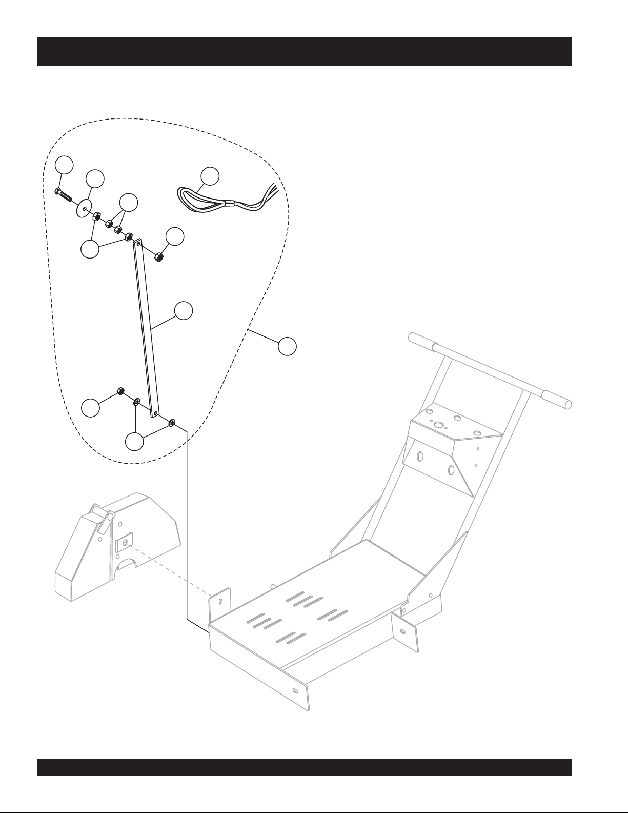
STOW CUTTER 1 CE SAW — POINTER ASSEMBLY
9
5
6
8
5
7
PAGE 16 — STOW CUTTER 1 CE — PARTS MANUAL — REV. #1 (12/20/07)
Page 17

STOW CUTTER 1 CE SAW — POINTER ASSEMBLY
POINTER ASSEMBLY
NO. PART NO. PART NAME QTY. REMARKS
1# 21017 SCREW, POINTER ARM 1
2# 29043-001 WHEEL, POINTER 1
3# 1007 NUT, HEX JAM 3/8 - 16 2
4# 1456 NUT, HEX FINISH 3/8 - 16 2
5# 10133 NUT, NYLOC 3/8 - 16 2
6# 27073-001 ARM, POINTER 1
7# 10136 WASHER, FLAT 3/8 2
8 25436 POINTER ASSEMBLY .................... 1 .......... INCLUDES ITEMS W/#
9# 15830 SASH ASSEMBLY 1
STOW CUTTER 1 CE — PARTS MANUAL — REV. #1 (12/20/07) — PAGE 17
Page 18

WATER TANK (OPTION)
5
STOW CUTTER 1 CE SAW — WATER TANK (OPTION)
4
14
3
1
11
6
10
8
12
7
9
2
13
PAGE 18 — STOW CUTTER 1 CE — PARTS MANUAL — REV. #1 (12/20/07)
Page 19

STOW CUTTER 1 CE SAW — WATER TANK (OPTION)
WATER TANK (OPTION)
NO. PART NO. PART NAME QTY. REMARKS
1 29290-351 SHELF, TANK 1
2 25494 INSTRUCTION SHEET 1
3 60002 HOSE, .375 ID X .5 OD TYGON PER FT 1
4 28862-001 CORD, BUNGEE 1
5 24778-003 FITTING, BRASS 3/8 BARB X 3/4 F GDN 1
6 4370 SCREW, HHC 3/8 - 16 X 2-1/4 2
6 1493 SCREW, HHC 3/8 - 16 X 3-1/4 2
7 2623 SCREW, HHC 5/16 - 16 X 1-1/4 2
8 10136 WASHER, FLAT SAE 3/8 2
9 0300 B WASHER, FLAT SAE 5/16 4
10 1266 A WASHER, LOCK 3/8 MED 2
11 28861-002 TRIM, RUBBER 2
12 29291-002 SPACER, TANK MOUNT, 2-3/8" 2
12 29291-001 SPACER, TANK MOUNT, 1-1/2" 2
13 0161 D NUT, HEX FINISH 5/16 - 18 2
14 28089-001 TANK, WATER, 5 GAL(18.95 LITERS) 1
STOW CUTTER 1 CE — PARTS MANUAL — REV. #1 (12/20/07) — PAGE 19
Page 20

AIR CLEANER ASSY.
HONDA GX390K1QWT2 ENGINE — AIR CLEANER ASSY.
PAGE 20 — STOW CUTTER 1 CE — PARTS MANUAL — REV. #1 (12/20/07)
Page 21

HONDA GX390K1QWT2 ENGINE — AIR CLEANER ASSY.
AIR CLEANER ASSY.
NO. PART NO. PART NAME QTY. REMARKS
1
16271ZE2000 GASKET, ELBOW 1
◊◊
◊
1
2 17210ZE3010 ELEMENT, AIR CLEANER ........................ 1 ......... INCLUDES ITEMS W/
3
*
4# 17219ZE3840 SEAL, AIR CLEANER COVER 1
5 17230ZE3841 COVER, AIR CLEANER (CYCLONE) 1
6
*
7# 17238ZE2310 COLLAR, AIR CLEANER 2
8
# 17239ZE3840 COLLAR B, AIR CLEANER 1
9 17410ZE3840 ELBOW, AIR CLEANER ............................ 1 ......... INCLUDES ITEMS W/#
10
10
11 17475ZE3841 CAP, PRE AIR CLEANER 1
12 17476ZE3841 GUIDE, PRE AIR CLEANER 1
13 90142MB0000 SCREW, PAN 5X16.5 5
14 90325044000 WINGNUT, TOOL BOX SETTING 2
15 90009ZE2003 BOLT- WASHER 6X22 1
16 9405006000 NUT, FLANGE 6MM 2
16271ZE2010 GASKET, ELBOW 1
◊◊
17218ZE3000 FILTER, OUTER 1
17232891000 GROMMET, AIR CLEANER 1
17470ZE3841 CASE, PRE AIR CLEANER 1
◊◊
◊
17470ZE3842 CASE, PRE AIR CLEANER 1
◊◊
*
NOTE
GX390K1QWT2: Model S/N DECEMBER 2005 AND BELOW
◊◊
◊
GX390U1QWT2: Model S/N JANUARY 2006 AND ABOVE
◊◊
STOW CUTTER 1 CE — PARTS MANUAL — REV. #1 (12/20/07) — PAGE 21
Page 22

CAMSHAFT ASSY.
HONDA GX390K1QWT2 ENGINE — CAMSHAFT ASSY.
PAGE 22 — STOW CUTTER 1 CE — PARTS MANUAL — REV. #1 (12/20/07)
Page 23

HONDA GX390K1QWT2 ENGINE — CAMSHAFT ASSY.
CAMSHAFT ASSY.
NO. PART NO. PART NAME QTY. REMARKS
1 14100ZF6W01 CAMSHAFT ASSEMBLY .......................... 1 ......... INCLUDES ITEM W/
2 14410ZE3013 ROD, PUSH 2
3 14431ZE2010 ARM, VALVE ROCKER 2
4 14441ZE2000 LIFTER, VALVE 2
5 14451ZE1013 PIVOT, ROCKER ARM 2
6
*
7 14711ZE3000 VALVE, INTAKE 1
8 14721ZE3000 VALVE, EXHAUST 1
9 14751ZE2003 SPRING, VALVE 2
10 14771ZE2000 RETAINER,INTAKE VALVE SPRING 1
11 14773ZE2000 RETAINER, EXHAUST VALVE SPRING 1
12 14775ZE2010 SEAT, VALVE SPRING 1
13 14781ZE2000 ROTATOR, VALVE 1
14 14791ZE2010 PLATE, PUSH ROD GUIDE 1
15 90012ZE0010 BOLT, PIVOT 8MM 2
16 90206ZE1000 NUT, PIVOT ADJ. 2
17 12209ZE8003 SEAL, VALVE STEM 1
14568ZE1000 SPRING, WEIGHT RETURN 1
*
NOTE
GX390K1QWT2: Model S/N DECEMBER 2005 AND BELOW
◊◊
◊
GX390U1QWT2: Model S/N JANUARY 2006 AND ABOVE
◊◊
STOW CUTTER 1 CE — PARTS MANUAL — REV. #1 (12/20/07) — PAGE 23
Page 24

CARBURETOR ASSY.
HONDA GX390K1QWT2 ENGINE — CARBURETOR ASSY.
PAGE 24 — STOW CUTTER 1 CE — PARTS MANUAL — REV. #1 (12/20/07)
Page 25

HONDA GX390K1QWT2 ENGINE — CARBURETOR ASSY.
CARBURETOR ASSY.
NO. PART NO. PART NAME QTY. REMARKS
1 16010ZE2812 CARBURETOR, GASKET SET 1 INCLUDES ITEMS W/+
2$ 16011ZA0931 VALVE SET, FLOAT 1
3$ 16013ZA0931 FLOAT SET 1
4$ 16015ZE8005 CHAMBER SET, FLOAT ...................... 1 ............. INCLUDES ITEM 4A
............................................................................. INCLUDES ITEM W/>
4A+ GASKET, CHAMBER SET FLOAT ...................... NOT SOLD SEPARATELY
5$ 16016ZH7W01 SCREW SET, PILOT 1
6$> 16024ZE1811 SCREW SET, DRAIN, .......................... 1 ............. INCLUDES ITEM 6A
6A+ GASKET, SCREW SET DRAIN ........................... NOT SOLD SEPARATELY
7$ 16028ZE0005 SCREW SET ....................................... 1 ............. INCLUDES ITEM 7A
7A+ GASKET, SCREW SET ....................................... NOT SOLD SEPARATELY
8$ 16044ZE3W20 CHOKE SET 1
9$ 16100ZF6V21 CARBURETOR ASSY. (BE85C B) ....... 1 ............. INCLUDES ITEMS W/$
10$ 16124ZE0005 SCREW, THROTTLE STOP 1
11$ 16166ZF6W10 NOZZLE, MAIN 1
12$+ 16173001004 GASKET, FUEL STRAINER CUP 1
13 16211ZF6000 INSULATOR, CARBURETOR 1
14 16220ZA0702 SPACER, CARBURETOR 1
15 16221ZF6800 GASKET, CARBURETOR 1
16 16223ZE3W00 GASKET, INSULATOR 1
20 16610ZE1000 LEVER, CHOKE (STD) ........................1 ............. INCLUDES ITEM W/
22$ 16953ZE1812 LEVER, VALVE 1
23$ 16954ZE1812 PLATE, LEVER SETTING 1
24$ 16956ZE1811 SPRING, VALVE LEVER 1
25$+ 16957ZE1812 GASKET, VALVE 1
26$ 16967ZE0811 CUP, FUEL STRAINER 1
28$ 93500030061H SCREW, PAN (3X6) 2
31
*
33$ 99101ZH80950 JET, MAIN (#95) (OPTIONAL) 1
33$ 99101ZH80980 JET, MAIN (#98) (OPTIONAL) 1
33$ 99101ZH81000 JET, MAIN (#100) 1
34$ 99204ZA00450 JET SET, PILOT (#45) ......................... 1............. INCLUDES ITEM 34A
34A+ GASKET, JET SET PILOT (#45) ......................... NOT SOLD SEPARATELY
35$ 16172ZE3W10 COLLAR, SET 1
9430520122 PIN, SPRING (2X12) 1
*
STOW CUTTER 1 CE — PARTS MANUAL — REV. #1 (12/20/07) — PAGE 25
Page 26

CONTROL ASSY.
HONDA GX390K1QWT2 ENGINE — CONTROL ASSY.
PAGE 26 — STOW CUTTER 1 CE — PARTS MANUAL — REV. #1 (12/20/07)
Page 27

HONDA GX390K1QWT2 ENGINE — CONTROL ASSY.
CONTROL ASSY.
NO. PART NO. PART NAME QTY. REMARKS
2 16551ZE3000 ARM, GOVERNOR 1
3 16555ZE3000 ROD, GOVERNOR 1
4 16561ZE3000 SPRING, GOVERNOR 1
5 16562ZE3000 SPRING, THROTTLE RETURN 1
6 16570ZE3W20 CONTROL ASSY. (REMOTE) .................... 1 ......... INCLUDES ITEMS W/
10
11
12
13
14
15
17
18
21 90013883000 BOLT, FLANGE (6X12) (CT200) 2
22 90015ZE5010 BOLT, GOVERNOR ARM 1
24
27
28
29 9405006000 NUT, FLANGE (6MM) 1
16571ZE3W00 LEVER, CONTROL 1
*
16574ZE1000 SPRING, LEVER 1
*
16575ZE2W00 WASHER, CONTROL LEVER 1
*
16576891000 HOLDER, CABLE 1
*
16578ZE1000 SPACER, CONTROL LEVER 1
*
16581ZE3W00 BASE, CONTROL 1
*
16584883300 SPRING, CONTROL ADJUSTING 1
*
16592883310 SPRING, CABLE RETURN 1
*
90114SA0000 NUT, SELF-LOCK (6MM) 1
*
93500050320A SCREW, PAN (5X32) 1
*
93500050160A SCREW, PAN (5X16) 1
*
*
STOW CUTTER 1 CE — PARTS MANUAL — REV. #1 (12/20/07) — PAGE 27
Page 28

CRANKCASE COVER ASSY.
HONDA GX390K1QWT2 ENGINE — CRANKCASE ASSY.
PAGE 28 — STOW CUTTER 1 CE — PARTS MANUAL — REV. #1 (12/20/07)
Page 29

HONDA GX390K1QWT2 ENGINE — CRANKCASE ASSY.
CRANKCASE COVER ASSY.
NO. PART NO. PART NAME QTY. REMARKS
2
2
◊◊
2
◊
◊◊
3 11381ZE3801 GASKET, CASE COVER 1
4 15600ZG4003 CAP ASSY., OIL FILLER ................................. 1 ................ INCLUDES ITEM W/#
5 15600735003 CAP ASSY., OIL FILLER ................................. 1 ................ INCLUDES ITEM W/
8#
*
9 16510ZE3000 GOVERNOR ASSY. .......................................... 1 ................ INCLUDES ITEMS W/+
10>%$+ 16511ZE8000 WEIGHT, GOVERNOR 3
11
>%$+ 16512ZE3000 HOLDER, GOVERNOR WEIGHT 1
12>%$+ 16513ZE2000 PIN, GOVERNOR WEIGHT 3
13
>$% 16531ZE2000 SLIDER, GOVERNOR ......................................1 ................ S/N 3287256 AND BELOW
13
>%$ 16531Z0A000 SLIDER, GOVERNOR ...................................... 1 ................ S/N 3287257 AND ABOVE
◊◊
13
◊
>%$ 16531Z0A000 SLIDER, GOVERNOR 1
◊◊
15>%$ 90602ZE1000 CLIP, GOVERNOR HOLDER 1
16 90701HC4000 PIN, DOWEL (8X12) 2
17>%$ 91201ZE3004 OIL SEAL (35X52X8) 1
18>%$ 9410106800 WASHER, PLAIN (6MM) 1
19 957010804000 BOLT, FLANGE (8X40) 7
20>%$ 961006202000 BEARING, RADIAL BALL (6202) 1
21>%$ 961006207000 BEARING, RADIAL BALL (6207) 1
11300ZE3602 COVER ASSY., CRANKCASE .........................1 ................ S/N 3287256 AND BELOW
............................................................................................ INCLUDES ITEMS W/>
11300ZE3604 COVER ASSY., CRANKCASE .........................1 ................ S/N 3287257 AND ABOVE
............................................................................................ INCLUDES ITEMS W/%
11300ZE3604 COVER ASSY., CRANKCASE .........................1 ................ INCLUDES ITEMS W/$
15625ZE1003 GASKET, OIL FILLER CAP 2
*
NOTE
GX390K1QWT2: Model S/N DECEMBER 2005 AND BELOW
◊◊
◊
GX390U1QWT2: Model S/N JANUARY 2006 AND ABOVE
◊◊
STOW CUTTER 1 CE — PARTS MANUAL — REV. #1 (12/20/07) — PAGE 29
Page 30

CRANKSHAFT ASSY.
HONDA GX390K1QWT2 ENGINE — CRANKSHAFT ASSY.
PAGE 30 — STOW CUTTER 1 CE — PARTS MANUAL — REV. #1 (12/20/07)
Page 31

HONDA GX390K1QWT2 ENGINE — CRANKSHAFT ASSY.
CRANKSHAFT ASSY.
NO. PART NO. PART NAME QTY. REMARKS
2
2
2
8 13351ZE3010 WEIGHT, BALANCER 1
11 90745ZE2600 KEY(6.3X6.3X43) 1
12
12
12
13310ZF6W10 CRANKSHAFT .......................................... 1 ......... INCLUDES ITEM W/
◊◊
◊
13310ZF6W11 CRANKSHAFT .......................................... 1 ......... INCLUDES ITEM W/#
◊◊
............................................................................... S/N 1113739 AND BELOW
◊◊
◊
13310ZF6W12 CRANKSHAFT .......................................... 1 ......... INCLUDES ITEM W/+
◊◊
..........................................................................
*91001ZF6003 BEARING, RADIAL BALL (6207S) 1
◊◊
◊
# 91001ZF6003 BEARING, RADIAL BALL (6207S) ............ 1 ......... S/N 1113739 AND BELOW
◊◊
◊◊
◊
+ 91001ZF6013 BEARING, RADIAL BALL (6207SH) ......... 1 ......... S/N 1113740 AND ABOVE
◊◊
S/N 1113740 AND ABOVE
*
NOTE
GX390K1QWT2: Model S/N DECEMBER 2005 AND BELOW
◊◊
◊
GX390U1QWT2: Model S/N JANUARY 2006 AND ABOVE
◊◊
STOW CUTTER 1 CE — PARTS MANUAL — REV. #1 (12/20/07) — PAGE 31
Page 32

HONDA GX390K1QWT2 ENGINE — CYLINDER BARREL ASSY.
CYLINDER BARREL ASSY.
PAGE 32 — STOW CUTTER 1 CE — PARTS MANUAL — REV. #1 (12/20/07)
Page 33

HONDA GX390K1QWT2 ENGINE — CYLINDER BARREL ASSY.
CYLINDER BARREL ASSY.
NO. PART NO. PART NAME QTY. REMARKS
1
◊◊
◊
1
◊◊
2
◊◊
2
◊
◊◊
◊◊
2
◊
◊◊
4 16541ZE3010 SHAFT, GOVERNOR ARM 1
9 90131883000 BOLT, DRAIN PLUG 12X15 2
10 90446KE1000 WASHER (8.2X17X0.8) 1
12 %# 91201ZE3004 OIL SEAL (35X52X8) 1
13 91203952771 OIL SEAL (8X14X5) 1
14 91353671004 O-RING (14MM) (NOK) 1
17 9405010000 NUT, FLANGE (10MM) 1
18 9410912000 WASHER, DRAIN PLUG (12MM) 2
19 9425110000 PIN, LOCK (10MM) 1
20 957010601200 BOLT, FLANGE (6X12) 2
21%# 961006202000 BEARING, RADIAL BALL (6202) 1
22
◊◊
22
◊
◊◊
◊◊
22
◊
◊◊
23 90013883000 BOLT, FLANGE (6X12) (CT200) 1
12000ZF6W13 CYLINDER ASSY. (ALERT) .................... 1 .............. INCLUDES ITEMS W/%
12000ZF6417 CYLINDER ASSY. ................................... 1 .............. INCLUDES ITEMS W/#
15510ZE2043 SWITCH ASSY., OIL LEVEL 1
15510ZE2043 SWITCH ASSY., OIL LEVEL .................. 1 .............. S/N 1412956 AND BELOW
15510ZE2053 SWITCH ASSY., OIL LEVEL .................. 1 .............. S/N 1412957 AND ABOVE
34150ZH7003 ALERT UNIT, OIL 1
34150ZH7003 ALERT UNIT, OIL.................................... 1 .............. S/N 1419413 AND BELOW
34150ZH7013 ALERT UNIT, OIL.................................... 1 .............. S/N 1419414 AND ABOVE
NOTE
GX390K1QWT2: Model S/N DECEMBER 2005 AND BELOW
◊◊
◊
GX390U1QWT2: Model S/N JANUARY 2006 AND ABOVE
◊◊
STOW CUTTER 1 CE — PARTS MANUAL — REV. #1 (12/20/07) — PAGE 33
Page 34

CYLINDER HEAD ASSY.
HONDA GX390K1QWT2 ENGINE — CYLINDER HEAD ASSY.
PAGE 34 — STOW CUTTER 1 CE — PARTS MANUAL — REV. #1 (12/20/07)
Page 35

HONDA GX390K1QWT2 ENGINE — CYLINDER HEAD ASSY.
CYLINDER HEAD ASSY.
NO. PART NO. PART NAME QTY. REMARKS
1
12200ZF6W01 CYLINDER HEAD .............................................1 ................ INCLUDES ITEMS W/
◊◊
1
2
*
3
*
4
*
5 12251ZF6W00 GASKET, CYLINDER HEAD 1
6 12310ZE3791 COVER, HEAD 1
7 12315ZE3840 TUBE, BREATHER 1
8 12391ZE2020 GASKET, CYLINDER HEAD COVER 1
10 17316611000 CLIP, BREATHER TUBE 2
11 90014ZE2000 BOLT, HEAD COVER 1
12 90042ZE8000 BOLT, STUD (8X131.5) 2
13 92900080320E BOLT 2, STUD (8X32) 2
14 90441ZE2010 WASHER, HEAD COVER 1
16 9430112200 PIN A, DOWEL (12X20) 2
17
17
17
18 9807955846 SPARK PLUG (BPR5ES) (NGK) (OPT.) 1
18 9807955855 SPARK PLUG (W16EPR-U) (DENSO) 1
18 9807956846 SPARK PLUG (BPR6ES) (NGK) 1
18 9807956855 SPARK PLUG (W20EPR-U) (DENSO) 1
12200ZF6406 CYLINDER HEAD .............................................1 ................ INCLUDES ITEMS W/%
◊
◊◊
% 12204ZE2306 GUIDE, VALVE (OS) (OPTIONAL) 1
% 12205ZE2305 GUIDE, EX. VALVE (OS) (OPTIONAL) 1
% 12216ZE2300 CLIP, VALVE GUIDE 1
957251008000 BOLT, FLANGE (10X80) 4
◊◊
◊
957251008000 BOLT, FLANGE (10X80) ...................................4 ................ S/N 1411816 AND BELOW
◊◊
◊◊
◊
957011008000 BOLT, FLANGE (10X80) ...................................4 ................ S/N 1411817 AND ABOVE
◊◊
*
NOTE
GX390K1QWT2: Model S/N DECEMBER 2005 AND BELOW
◊◊
◊
GX390U1QWT2: Model S/N JANUARY 2006 AND ABOVE
◊◊
STOW CUTTER 1 CE — PARTS MANUAL — REV. #1 (12/20/07) — PAGE 35
Page 36

FAN COVER ASSY.
HONDA GX390K1QWT2 ENGINE — FAN COVER ASSY.
PAGE 36 — STOW CUTTER 1 CE — PARTS MANUAL — REV. #1 (12/20/07)
Page 37

HONDA GX390K1QWT2 ENGINE — FAN COVER ASSY.
FAN COVER ASSY.
NO. PART NO. PART NAME QTY. REMARKS
4 16731ZE2003 CLIP, TUBE 1
7 19610ZE3010ZB COVER, FAN *NH1* (BLACK) 1
10 19631ZE3W00 SHROUD 1
13
36100ZH7003 SWITCH ASSY., ENGINE STOP 1
◊◊
13
◊
36100ZF6P81 SWITCH ASSY., ENGINE STOP .................1 .............. S/N 1412956 AND BELOW
◊◊
◊◊
◊
13
15 90013883000 BOLT, FLANGE (6X12) (CT200) 6
36100ZF6P82 SWITCH ASSY., ENGINE STOP .................1 .............. S/N 1412957 AND ABOVE
◊◊
NOTE
GX390K1QWT2: Model S/N DECEMBER 2005 AND BELOW
◊◊
◊
GX390U1QWT2: Model S/N JANUARY 2006 AND ABOVE
◊◊
STOW CUTTER 1 CE — PARTS MANUAL — REV. #1 (12/20/07) — PAGE 37
Page 38

FLYWHEEL ASSY.
HONDA GX390K1QWT2 ENGINE — FLYWHEEL ASSY.
PAGE 38 — STOW CUTTER 1 CE — PARTS MANUAL — REV. #1 (12/20/07)
Page 39

HONDA GX390K1QWT2 ENGINE — FLYWHEEL ASSY.
FLYWHEEL ASSY.
NO. PART NO. PART NAME QTY. REMARKS
1 19511ZE3000 FAN, COOLING 1
3 28450ZE3W11 PULLEY, STARTER (SCREEN GRID) 1
7 31100ZE3701 FLYWHEEL 1
10
10
10
11 90741ZE2000 KEY, SPECIAL WOODRUFF (25X18) 1
90201ZE3V00 NUT, SPECIAL (16MM) (1) 1
◊◊
◊
90201ZE3V00 NUT, SPECIAL (16MM) (1) ........................... 1 ..............S/N 1317976 AND BELOW
◊◊
◊◊
◊
90201ZE3790 NUT, SPECIAL (16MM) (1) ...........................1 .............. S/N 1317977 AND ABOVE
◊◊
NOTE
GX390K1QWT2: Model S/N DECEMBER 2005 AND BELOW
◊◊
◊
GX390U1QWT2: Model S/N JANUARY 2006 AND ABOVE
◊◊
STOW CUTTER 1 CE — PARTS MANUAL — REV. #1 (12/20/07) — PAGE 39
Page 40

FUEL TANK ASSY.
HONDA GX390K1QWT2 ENGINE — FUEL TANK ASSY.
PAGE 40 — STOW CUTTER 1 CE — PARTS MANUAL — REV. #1 (12/20/07)
Page 41

HONDA GX390K1QWT2 ENGINE — FUEL TANK ASSY.
FUEL TANK ASSY.
NO. PART NO. PART NAME QTY. REMARKS
1 16854ZH8000 RUBBER, SUPPORTER (107MM) 1
3 16955ZE1000 JOINT, FUEL TANK 1
6
17510ZE3010ZB TANK, FUEL *NH1* 1
◊◊
6
6
6
8
8
9
*
9# 17631Z0T812 GASKET, FUEL FILLER CAP 39X62X3 1
15 91353671004 O-RING (14MM) (NOK) 1
17 9405008000 NUT, FLANGE (8MM) 2
18
18
18
20
20
20
22 957010802500 BOLT, FLANGE (8X25) 2
17510ZE3020ZB TANK, FUEL *NH1* ........................................... 1.......... S/N 1213085 AND BELOW
◊
◊◊
◊◊
◊
17510ZE3800ZA TANK, FUEL *NH1* ........................................... 1.......... S/N 1213086 THRU 1383799
◊◊
◊◊
◊
17510ZE3801ZA TANK, FUEL *NH1* ........................................... 1.......... S/N 1383800 AND ABOVE
◊◊
17620ZH7023 CAP, FUEL FILLER (BLACK) ............................ 1.......... INCLUDES ITEM W/
◊◊
◊
17620Z0T305 CAP, FUEL FILLER (CHROME PLATED) .......... 1.......... INCLUDES ITEM W/#
◊◊
17631ZH7003 GASKET, FUEL FILLER CAP 1
950014523540 BULK HOSE, FUEL (4.5X235) .......................... 1.......... REPLACES 950014500160M
◊◊
◊
950014523540 BULK HOSE, FUEL (4.5X235) .......................... 1.......... REPLACES 950014500160M
◊◊
....................................................................................... S/N 1105013 AND BELOW
◊◊
◊
91424Z5L801 BULK HOSE, FUEL (4.5X235) (FKM) ............... 1.......... S/N 1105014 AND ABOVE
◊◊
9500202080 CLIP, TUBE (B8) 2
◊◊
◊
9500202080 CLIP, TUBE (B8) ................................................ 2.......... S/N 1105013 AND BELOW
◊◊
◊◊
◊
950024080008 CLAMP, TUBE (D8) ........................................... 2.......... S/N 1105014 AND ABOVE
◊◊
*
NOTE
GX390K1QWT2: Model S/N DECEMBER 2005 AND BELOW
◊◊
◊
GX390U1QWT2: Model S/N JANUARY 2006 AND ABOVE
◊◊
STOW CUTTER 1 CE — PARTS MANUAL — REV. #1 (12/20/07) — PAGE 41
Page 42

IGNITION COIL ASSY.
HONDA GX390K1QWT2 ENGINE — IGNITION COIL ASSY.
PAGE 42 — STOW CUTTER 1 CE — PARTS MANUAL — REV. #1 (12/20/07)
Page 43

HONDA GX390K1QWT2 ENGINE — IGNITION COIL ASSY.
IGNITION COIL ASSY.
NO. PART NO. PART NAME QTY. REMARKS
1
30500ZF6W02 COIL ASSY., IGNITION 1
◊◊
1
◊
30500ZF6W02 COIL ASSY., IGNITION ..................................... 1.......... S/N 1411816 AND BELOW
◊◊
◊◊
◊
1
2 30700ZE1013 CAP ASSY., NOISE SUPPRESSOR 1
8 31512ZE2000 GROMMET, WIRE 1
12 36101ZE2701 WIRE, STOP SWITCH (430MM) 1
17 90015883000 BOLT, FLANGE (6X28) 2
18 90684ZA0601 CLIP, WIRE HARNESS 1
30500ZF6W03 COIL ASSY., IGNITION ..................................... 1.......... S/N 1411817 AND ABOVE
◊◊
GX390K1QWT2: Model S/N DECEMBER 2005 AND BELOW
NOTE
◊◊
◊
GX390U1QWT2: Model S/N JANUARY 2006 AND ABOVE
◊◊
STOW CUTTER 1 CE — PARTS MANUAL — REV. #1 (12/20/07) — PAGE 43
Page 44

MUFFLER ASSY.
HONDA GX390K1QWT2 ENGINE — MUFFLER ASSY.
PAGE 44 — STOW CUTTER 1 CE — PARTS MANUAL — REV. #1 (12/20/07)
Page 45

HONDA GX390K1QWT2 ENGINE — MEFFLER ASSY.
MUFFLER ASSY.
NO. PART NO. PART NAME QTY. REMARKS
2 18310ZE2W61 MUFFLER 1
3 18320ZE2W61 PROTECTOR, MUFFLER 1
5 18330ZE2W00 PIPE, EX. 1
6
18331ZE3810 CAP, MUFFLER 1
◊◊
◊
6
6
7 18333ZF6W01 GASKET, EX. PIPE 1
8 18355ZE2W00 ARRESTER, SPARK (OPTIONAL) 1
9 18381ZE2W10 GASKET, MUFFLER (ARRESTER) (OPTIONAL) 1
10 18381ZE2800 GASKET, MUFFLER 1
19 90050ZE1000 SCREW, TAPPING (5X8) 4
22 90055ZE1000 SCREW, TAPPING (4X6) 3
27 90006ZE2000 SCREW, TAPPING (6X10) 1
28 9405008000 NUT, FLANGE (8MM) 5
31 90055ZE1000 SCREW, TAPPING (4X6) 1
18331ZE3810 CAP, MUFFLER...................................................... 1 ......... S/N 1166160 AND BELOW
◊◊
◊◊
◊
18331ZE3811 CAP, MUFFLER...................................................... 1 ......... S/N 1166161 AND ABOVE
◊◊
NOTE
GX390K1QWT2: Model S/N DECEMBER 2005 AND BELOW
◊◊
◊
GX390U1QWT2: Model S/N JANUARY 2006 AND ABOVE
◊◊
STOW CUTTER 1 CE — PARTS MANUAL — REV. #1 (12/20/07) — PAGE 45
Page 46

PISTON ASSY.
HONDA GX390K1QWT2 ENGINE — PISTON ASSY.
PAGE 46 — STOW CUTTER 1 CE — PARTS MANUAL — REV. #1 (12/20/07)
Page 47

HONDA GX390K1QWT2 ENGINE — PISTON ASSY.
PISTON ASSY.
NO. PART NO. PART NAME QTY. REMARKS
1 13010ZF6005 RING SET, PISTON (STD) 1
1 13011ZF6005 RING SET, PISTON (0.25) 1
1 13012ZF6005 RING SET, PISTON (0.50) 1
1 13013ZF6005 RING SET, PISTON (0.75) 1
2 13101ZF6W00 PISTON (STD) 1
2 13102ZF6W00 PISTON (0.25) 1
2 13103ZF6W00 PISTON (0.50) 1
2 13104ZF6W00 PISTON (0.75) 1
3 13111ZF6W00 PIN, PISTON 1
4 13200ZE3020 ROD ASSY., CONNECTING (STD) ........................ 1 ......... INCLUDES ITEM W/
4 13200ZE3315 ROD ASSY., CONNECTING (0.25 UNDERSIZE) 1
5
*
6 90601ZE3000 CLIP, PISTON PIN (20MM) 2
90001ZE8000 BOLT, CONNECTING ROD 2
*
STOW CUTTER 1 CE — PARTS MANUAL — REV. #1 (12/20/07) — PAGE 47
Page 48

HONDA GX390K1QWT2 ENGINE — RECOIL STARTER ASSY.
RECOIL STARTER ASSY.
PAGE 48 — STOW CUTTER 1 CE — PARTS MANUAL — REV. #1 (12/20/07)
Page 49

HONDA GX390K1QWT2 ENGINE — RECOIL STARTER ASSY.
RECOIL STARTER ASSY.
NO. PART NO. PART NAME QTY. REMARKS
1 28400ZE3W01ZB STARTER ASSY., RECOIL *NH1* (BLACK) .............. 1 ...... INCLUDES ITEMS W/
2
*
3
*
4
*
5
*
6
*
7
*
8
*
10
11
11
13
14 90008ZE2003 BOLT, FLANGE (6X10) 3
28410ZE3W01ZB CASE, RECOIL STARTER *NH1* (BLACK) 1
28421ZE3W01 PULLEY, RECOIL STARTER 1
28422ZE2W01 RATCHET, STARTER 2
28441ZE2W01 SPRING, FRICTION 1
28442ZE2W01 SPRING, STARTER RETURN 1
28443ZE2W01 SPRING, RATCHET 2
28444ZE2W01 RETAINER, SPRING 1
28461ZE2W02 GRIP, STARTER 1
*
*28462ZV7003 ROPE, RECOIL STARTER 1
◊◊
◊*28462ZE3W01 ROPE, RECOIL STARTER 1
◊◊
90004ZE2W01 SCREW, CENTER 1
*
*
NOTE
GX390K1QWT2: Model S/N DECEMBER 2005 AND BELOW
◊◊
◊
GX390U1QWT2: Model S/N JANUARY 2006 AND ABOVE
◊◊
STOW CUTTER 1 CE — PARTS MANUAL — REV. #1 (12/20/07) — PAGE 49
Page 50

LABELS ASSY.
HONDA GX390K1QWT2 ENGINE — LABELS ASSY.
PAGE 50 — STOW CUTTER 1 CE — PARTS MANUAL — REV. #1 (12/20/07)
Page 51

HONDA GX390K1QWT2 ENGINE — LABELS ASSY.
LABELS ASSY.
NO. PART NO. PART NAME QTY. REMARKS
1
87522ZH9010 LABEL, CAUTION(ENGLISH ETC.) 1
◊◊
1
1
2
2
2
3
4 87534ZE1841 LABEL, AIR CLEANER CAUTION 1
5
6
7
87516ZH7000 MARK OPERATOR CAUTION 1
◊
◊◊
◊◊
87516ZH7810 MARK OPERATOR PICTOGRAPH (OPTION) 1
◊
◊◊
87521ZF6W02 EMBLEM (GX390 HONDA 13.0) 1
◊◊
◊
87521ZF6W03 EMBLEM (GX390 HONDA 13.0) ............................ 1 ............ S/N 1398206 AND BELOW
◊◊
◊◊
◊
87521ZF6W04 EMBLEM (GX390 HONDA 13.0) ............................ 1 ............ S/N 1398207 AND ABOVE
◊◊
◊◊
◊
87532ZH7000 MARK, THROTTLE INDICATION 1
◊◊
◊◊
87535ZE1841 MARK, AIR CLEANER SALES POINT 1
◊
◊◊
87532ZH8810 MARK, OIL ALERT (E) 1
87528ZE2810 MARK, CHOKE (EXTERNAL) 1
NOTE
GX390K1QWT2: Model S/N DECEMBER 2005 AND BELOW
◊◊
◊
GX390U1QWT2: Model S/N JANUARY 2006 AND ABOVE
◊◊
STOW CUTTER 1 CE — PARTS MANUAL — REV. #1 (12/20/07) — PAGE 51
Page 52

TERMS AND CONDITIONS OF SALE — PARTS
Terms and Conditions of Sale
STOW Construction Equipment
PAYMENT TERMS
Terms of payment for unit sales are 2% 15 days
net 30 days from date of invoice unless
otherwise specifically stated on our invoice.
Parts invoices have terms of net 10 days.
Minimum parts billing is $15.00 net.
Applicable discounts will be computed on
merchandise value only. Late charges will be
assessed at prevailing rates. Cash discounts
cannot be taken on current billings if any
previously billed amounts are past due.
FREIGHT POLICY
Freight policy is established to offer customers
every advantage possible. Due to bulk freight
ratings on some equipment and other shipping
considerations, freight policies differ by
equipment type. Actual back freight may be
charged for shipments originating from other
than specified FOB warehouses. See Freight
Policy for details.
All STOW domestic sales are FOB nearest
available designated MQ/STOW warehouse.
Export orders are ex-works factory located in
Carson, CA or Boise, ID.
Additions to orders already shipped cannot be
accepted for freight minimums.
Should STOW elect to make partial shipments
of an order originally complying with the “freight
allowed” requirements, transportation charges
will be absorbed by STOW on any subsequent
shipment applying to that order.
All other orders will be shipped collect or
prepaid with charges added to the invoice.
STOW’s responsibility ceases when a signed
manifest has been obtained from the carrier,
and any claim for shortage or damage must
be settled between the consignee and the
carrier.
Parts: FOB Carson, California or Boise,
Idaho. See Freight Policy for details and
additional discounts.
DROP SHIPMENTS
STOW reserves the right to refuse Drop
Shipments outside the normal service area of
the purchasing dealer.
FIELD WAREHOUSES
Field Warehouses are currently located in
California, Georgia, Idaho, Iowa, and New
Jersey
SPECIAL EXPEDITING SERVICE
The higher of a $35.00 surcharge or actual
costs will be added to the invoice for special
handling, including bus shipments, or in cases
where STOW personnel must personally
deliver the equipment or parts to the carrier.
RETURNED GOODS POLICY
Return shipments may be accepted and credit
allowed, subject to the following provisions.
1. A Returned Material Authorization (RMA)
must be approved by STOW prior to
shipment. Approvals for returned goods
must be with just cause and are at the
sole discretion of STOW. A copy of the
Authorization must accompany the shipment to the designated Warehouse.
2. Parts being returned must be listed as
currently supplied on the current parts list.
3. Parts must be in new and resalable condition
in the original package, with part numbers
clearly marked.
4. Units and accessories must be current
models in the latest price list and in new
and resalable condition.
5. Special order items are not returnable for
credit.
6. Credit on returned parts and units will be
issued at actual dealer net price at time of
purchase less 15% restocking charge.
7. All returned shipments are to be made to
the STOW designated receiving point,
freight prepaid at the sender’s expense.
The sender will be notified of any material
received that does not meet the above
provisions. Such material will be held for 30 days
from notification pending instructions. If a reply
is not received within 30 days, the material will
be returned to the sender at his expense with
no credit issued.
PRICING, REBATES AND
SPECIFICATIONS
Every effort will be made to provide adequate
notice of changes; however, prices and
equipment specifications are subject to change
without notice.
Price changes are effective on a specific date
and all orders received on or after that date will
be billed at the revised price.
Rebates for price reductions and added charges
for price increases will not be made for stock in
dealer inventory at the time of a price change.
STOW reserves the right to quote and sell direct
to Government agencies and to Original
Equipment Manufacturer accounts who use our
products as integral parts of their own products.
LIMITATION OF SELLER’S LIABILITY
STOW shall not be liable hereunder for damages
in excess of the purchase price of the item with
respect to which damages are claimed and in
no event shall STOW be liable for loss of profit
or good will or for any other special, consequential
or incidental damages.
LIMITATION OF WARRANTIES
There are no warranties, express or implied,
made by STOW. hereunder on Products
manufactured or distributed by it except the
warranty against defects in material and
workmanship on new Products to the original
purchaser, as set forth in the STOW New Product
Limited Warranty.
Effective: July 15, 2003
STOW CONSTRUCTION EQUIPMENT
POST OFFICE BOX 6254
CARSON, CALIFORNIA 90749
310-661-4242 • 877-BUY-STOW
FAX: 310-604-9237
Atlanta • Boise • Newark • Quebec, Canada
Manchester, UK • Rio de Janeiro, BR • Puebla, MX
E-MAIL: stow@stowmfg.com
www.stowmfg.com
PAGE 52 — STOW CUTTER 1 CE — PARTS MANUAL — REV. #1 (12/20/07)
Page 53

NOTE PAGE
STOW CUTTER 1 CE — PARTS MANUAL — REV. #1 (12/20/07) — PAGE 53
Page 54

PARTS MANUAL
HERE’S HOW TO GET HELP
PLEASE HAVE THE MODEL AND SERIAL
NUMBER
ON-HAND
WHEN CALLING
PARTS DEPARTMENT
800-427-1244 FAX: 800-672-7877
310-537-3700 FAX: 310-637-3284
SERVICE DEPARTMENT
800-478-1244 FAX: 310-537-4259
310-537-3700
TECHNICAL ASSISTANCE
800-478-1244 FAX: 310-631-5032
WARRANTY DEPARTMENT
800-421-1244, EXT. 279 FAX: 310-537-1173
310-537-3700, EXT. 279
SALES DEPARTMENT
310-661-4242 FAX: 310-604-9237
877-289-7869 (877-BUY-STOW)
© COPYRIGHT 2007, MULTIQUIP INC.
Multiquip Inc, and the STOW logo are registered trademarks of Multiquip Inc. and may not be used, reproduced, or altered without written permission. All other
trademarks are the property of their respective owners and used with permission.
This manual MUST accompany the equipment at all times. This manual is considered a permanent part of the equipment and should remain with the unit if resold.
The information and specifications included in this publication were in effect at the time of approval for printing. Illustrations, descriptions, references and technical
data contained in this manual are for guidance only and may not be considered as binding. Multiquip Inc. reserves the right to discontinue or change specifications,
design or the information published in this publication at any time without notice and without incurring any obligations.
Your Local Dealer is:
Atlanta • Boise • Newark • Quebec, Canada
Manchester, UK • Rio de Janeiro, BR • Puebla, MX
MQ STOW CONSTRUCTION EQUIPMENT
A DIVISION OF MULTIQUIP INC.
POST OFFICE BOX 6254
CARSON, CA 90749
310-537-3700 • 888-252-MQ STOW [888252-7869]
FAX: 310-537-1986 • FAX: 800-556-1986
E-MAIL: MQ STOW@multiquip.com • WWW:
stowmfg.com
 Loading...