

Page 1

OPERATION MANUAL
SERIES
MODEL CA4HM
WALK-BEHIND TROWEL
(HONDA
KOHLER 27 HP
GX120K1QX2/GX120UT1QX2
KOHLER 28 HP EFI
GASOLINE ENGINE)
Revision #3 (10/28/10)
To find the latest revision of this
publication, visit our website at:
www.multiquip.com
THIS MANUAL MUST ACCOMPANY THE EQUIPMENT AT ALL TIMES.
P/N 21518
Page 2

PROPOSITION 65 WARNING
Engine exhaust and some of
its constituents, and some dust created
by power sanding, sawing, grinding,
drillingandotherconstructionactivities
contains chemicals known to the State
of California to cause cancer, birth
defects and other reproductive harm.
Some examples of these chemicals are:
Leadfromlead-basedpaints.
Crystallinesilicafrombricks.
Cementandothermasonryproducts.
Arsenicandchromiumfrom chemically
treatedlumber.
Your risk from these exposures varies,
dependingonhowoftenyoudothistype
of work. To reduce your exposure to
these chemicals: work in aALWAYS
well ventilated area, and work with
approved safety equipment, such as
dust masks that are specially designed
to filter out microscopic particles.
PAGE 2 — CA4HM WALK-BEHIND TROWEL — OPERATION MANUAL — REV. #3 (10/28/10)
Page 3
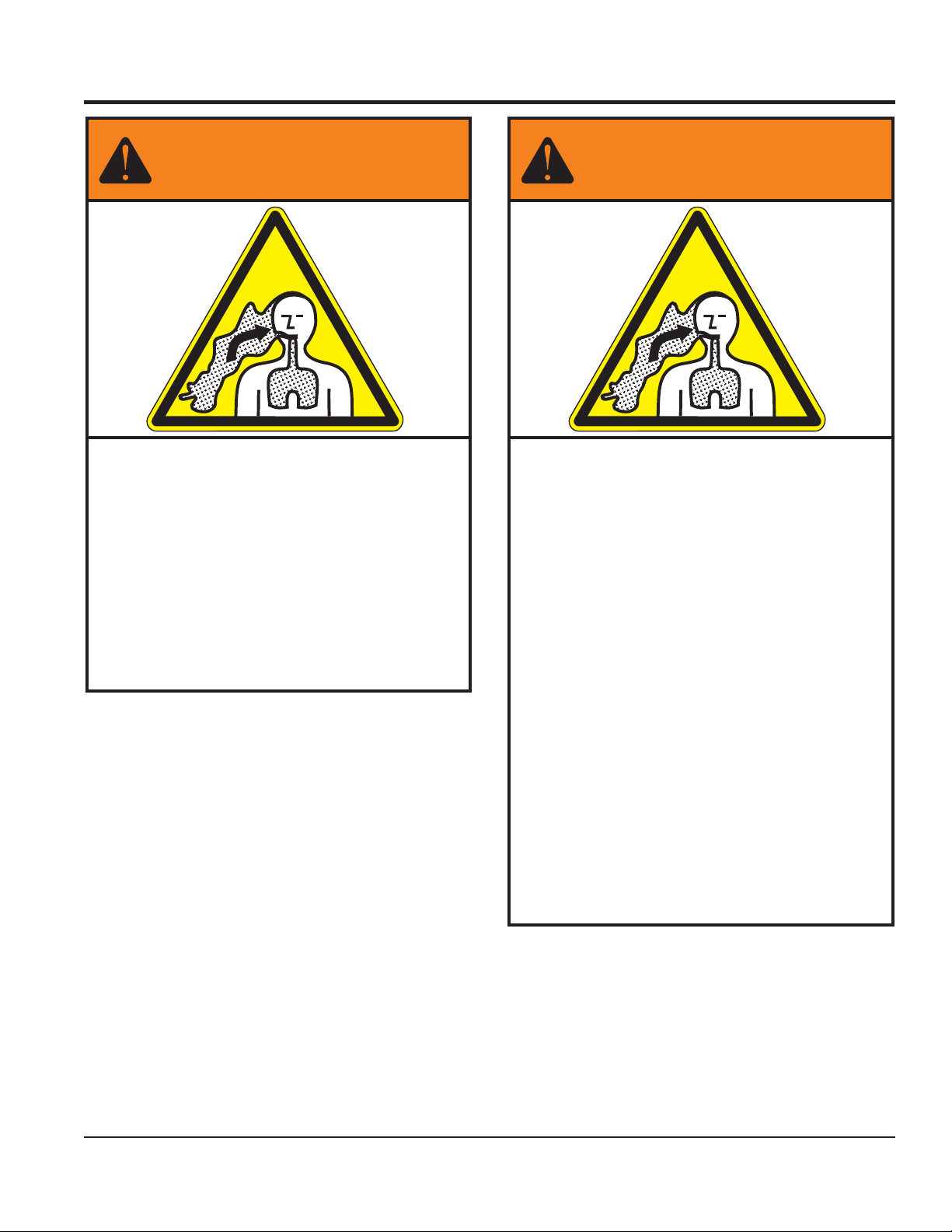
SILICOSIS/RESPIRATORY WARNINGS
WARNING
SILICOSIS WARNING RESPIRATORY HAZARDS
Grinding/cutting/drilling of masonry, concrete, metaland
other materials with silica in their composition may give
off dust or mists containing crystalline silica. Silica is a
basic component of sand, quartz, brick clay, granite and
numerous other minerals and rocks. Repeated and/or
substantial inhalation of airborne crystalline silica can
cause serious or fatal respiratory diseases, including
silicosis. In addition, California and some other
authorities have listed respirable crystalline silica as a
substance known to cause cancer. When cutting such
materials, always follow the respiratory precautions
mentioned above.
WARNING
Grinding/cutting/drilling of masonry, concrete, metaland
other materials can generate dust, mists and fumes
containing chemicals known to cause serious or fatal
injury or illness, such as respiratory disease, cancer,
birth defects or other reproductive harm. If you are
unfamiliar with the risks associated with the particular
process and/or material being cut or the composition of
the tool being used, review the material safety data
sheet and/or consult your employer, the material
manufacturer/supplier, governmental agencies such as
OSHA and NIOSH and other sources on hazardous
materials. California and some other authorities, for
instance, have published lists of substances known to
cause cancer, reproductive toxicity, or other harmful
effects.
Control dust, mist and fumes at the source where
possible. In this regard use good work practices and
follow the recommendations of the manufacturers or
suppliers, OSHA/NIOSH, and occupational and trade
associations. Water should be used for dust
suppression when wet cutting is feasible. When the
hazards from inhalation of dust, mists and fumes cannot
be eliminated, the operator and any bystanders should
always wear a respirator approved by NIOSH/MSHA for
the materials beingused.
CA4HM WALK-BEHIND TROWEL — OPERATION MANUAL — REV. #3 (10/28/10) — PAGE 3
Page 4

MQ WHITEMAN CA4HM
WALK-BEHIND TROWEL
Proposition 65 Warning ............................................. 2
Silicosis/Respiratory Warnings .................................. 3
Training Checklist ...................................................... 5
Daily Pre-Operation Checklist ................................... 6
Safety Information ................................................ 7-11
Dimensions ............................................................. 12
Specifications .......................................................... 13
General Information ................................................ 14
Components............................................................ 15
Basic Engine ........................................................... 16
Assembly ................................................................. 17
Inspection ........................................................... 18-19
Operation ........................................................... 20-23
Options .................................................................... 24
Maintenance ...................................................... 25-30
Troubleshooting ................................................. 31-34
Engine Wiring Diagram ........................................... 35
TABLE OF CONTENTS
NOTICE
Specifications are subject to change without notice
PAGE 4 — CA4HM WALK-BEHIND TROWEL — OPERATION MANUAL — REV. #3 (10/28/10)
Page 5

TRAINING CHECKLIST
tsilkcehCgniniarT
.oN noitpircseD ?KO etaD
1 .yletelpmoclaunaMs’rotarepOdaeR
2
3 .erudecorpgnileufer,metsysleuF
4 .sthgildnayarpsfonoitarepO
5 .)gninnurtonenihcam(slortnocfonoitarepO
6 .noitarepohctiwspotsytefas,slortnocytefaS
7 .serudecorppotsycnegremE
8 .ekohcenigne,taeh-erp,enihcamfoputratS
9 .revohagniniatniaM
01 .gnirevuenaM
11 .gnihctiP
21 ™hctiP-niwT.hctipedalbgnihctaM
31 .seuqinhcetgnihsinifetercnoC
dnaenignefognikcehc,stnenopmocfonoitacol,tuoyalenihcaM
.slevelliociluardyh
41 .enihcamfonwodtuhS
51 .)spooltfil(enihcamfognitfiL
61 .egarotsdnatropsnartenihcaM
CA4HM WALK-BEHIND TROWEL — OPERATION MANUAL — REV. #3 (10/28/10) — PAGE 5
Page 6

DAILY PRE-OPERATION CHECKLIST
1 .levellioenignE
2 .levelliociluardyH
3 .leveltnaloocrotaidaR
4 .sedalbfonoitidnoC
5 .noitarepohctipedalB
6 .noitarepohctiwSpotSytefaS
7 .noitarepolortnocgnireetS
tsilkcehCnoitarepO-erPyliaD
PAGE 6 — CA4HM WALK-BEHIND TROWEL — OPERATION MANUAL — REV. #3 (10/28/10)
Page 7
SAFETY INFORMATION
Do not operate or service the equipment before reading
the entire manual. Safety precautions should be followed
at all times when operating this equipment.
Failure to read and understand the safety
messages and operating instructions could
result in injury to yourself and others.
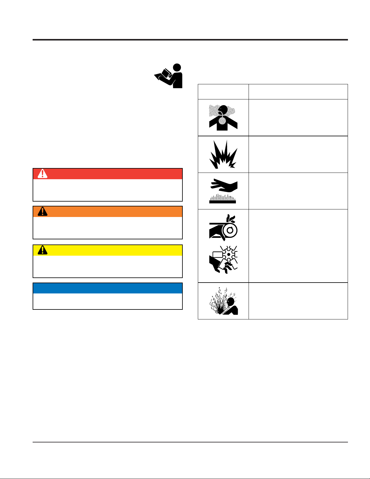
SAFETY MESSAGES
The four safety messages shown below will inform you
about potential hazards that could injure you or others. The
safety messages specifically address the level of exposure
to the operator and are preceded by one of four words:
DANGER, WARNING, CAUTION or NOTICE.
SAFETY SYMBOLS
DANGER
Indicates a hazardous situation which, if not avoided,
WILL result in DEATH or SERIOUS INJURY.
WARNING
Potential hazards associated with the operation of this
equipment will be referenced with hazard symbols which
may appear throughout this manual in conjunction with
safety messages.
Symbol Safety Hazard
Lethal exhaust gas hazards
Explosive fuel hazards
Burn hazards
Indicates a hazardous situation which, if not avoided,
COULD result in DEATH or SERIOUS INJURY.
CAUTION
Indicates a hazardous situation which, if not avoided,
COULD result in MINOR or MODERATE INJURY.
NOTICE
Addresses practices not related to personal injury.
Rotating parts hazards
Pressurized fluid hazards
CA4HM WALK-BEHIND TROWEL — OPERATION MANUAL — REV. #3 (10/28/10) — PAGE 7
Page 8
SAFETY INFORMATION
GENERAL SAFETY
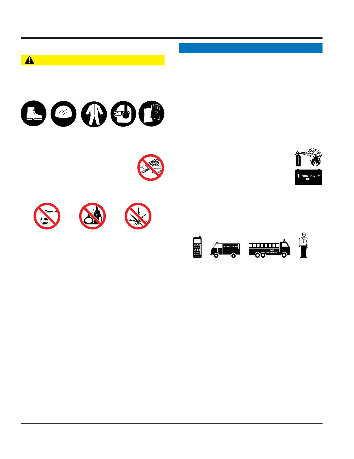
CAUTION
NEVER operate this equipment without proper protective
clothing, shatterproof glasses, respiratory protection,
hearing protection, steel-toed boots and other protective
devices required by the job or city and state regulations.
Avoid wearing jewelry or loose fitting clothes that may
snag on the controls or moving parts as this can cause
serious injury.
NEVER operate this equipment when not
feeling well due to fatigue, illness or when
under medication.
NEVER operate this equipment under the
influence of drugs or alcohol.
NOTICE
This equipment should only be operated by trained and
qualified personnel 18 years of age and older.
Whenever necessary, replace nameplate, operation and
safety decals when they become difficult read.
Manufacturer does not assume responsibility for any
accident due to equipment modifications. Unauthorized
equipment modification will void all warranties.
NEVER use accessories or attachments that are not
recommended by Multiquip for this equipment. Damage
to the equipment and/or injury to user may result.
ALWAYS know the location of the nearest
fire extinguisher.
ALWAYS know the location of the nearest
first aid kit.
ALWAYS know the location of the nearest phone or keep
a phone on the job site. Also, know the phone numbers
of the nearest ambulance, doctor and fire department.
This information will be invaluable in the case of an
emergency.
ALWAYS clear the work area of any debris, tools, etc.
that would constitute a hazard while the equipment is
in operation.
No one other than the operator is to be in the working
area when the equipment is in operation.
DO NOT use the equipment for any purpose other than
its intended purposes or applications.
PAGE 8 — CA4HM WALK-BEHIND TROWEL — OPERATION MANUAL — REV. #3 (10/28/10)
Page 9
SAFETY INFORMATION
TROWEL SAFETY
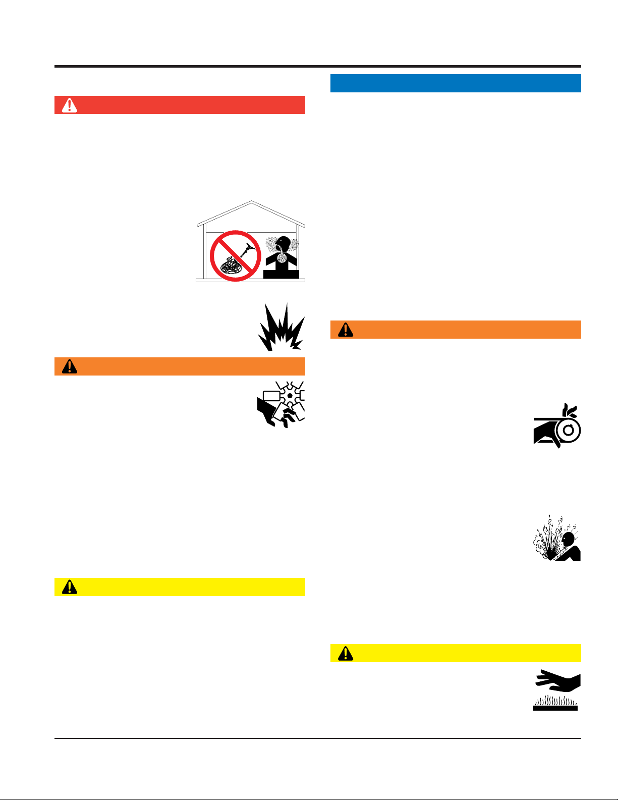
DANGER
Engine fuel exhaust gases contain poisonous carbon
monoxide. This gas is colorless and odorless, and can
cause death if inhaled.
The engine of this equipment requires an adequate free
flow of cooling air. NEVER operate this equipment in any
enclosed or narrow area
where free flow of the air is
restricted. If the air flow is
restricted it will cause injury
to people and property and
serious damage to the
equipment or engine.
NEVER operate the equipment in an explosive
atmosphere or near combustible materials. An
explosion or fire could result causing severe
bodily harm or even death.
WARNING
DANGEROUS
GAS FUMES
NOTICE
ALWAYS keep the machine in proper running condition.
Fix damage to machine and replace any broken parts
immediately.
ALWAYS store equipment properly when it is not being
used. Equipment should be stored in a clean, dry location
out of the reach of children and unauthorized personnel.
A safety manual for operating and maintenance
personnel of concrete power trowels produced by the
Association of Equipment Manufacturers (AEM) can be
obtained for a fee by ordering through their website at
www.aem.org.
Order FORM PT-160
ENGINE SAFETY
WARNING
DO NOT place hands or fingers inside engine
compartment when engine is running.
ALWAYS keep clear of rotating or moving
parts while operating the trowel.
DO NOT start or operate the trowel if the
drive train will not disengage. Centrifugal
force between the trowel and surface when starting can
cause uncontrolled handle movement that can cause
serious injury. The handle must not move while pulling
the engine recoil starter.
NEVER disconnect any emergency or safety devices.
These devices are intended for operator safety.
Disconnection of these devices can cause severe injury,
bodily harm or even death. Disconnection of any of these
devices will void all warranties.
CAUTION
NEVER stand on trowel during operation.
NEVER lubricate components or attempt service on a
running machine.
NEVER place your feet or hands inside the guard rings
while starting or operating this equipment.
NEVER operate the engine with heat shields or
guards removed.
Keep fingers, hands hair and clothing away
from all moving parts to prevent injury.
DO NOT remove the radiator cap while the
engine is hot. High pressure boiling water will gush out
of the radiator and severely scald any persons in the
general area of the trowel.
DO NOT remove the coolant drain plug
while the engine is hot. Hot coolant will
gush out of the coolant tank and severely
scald any persons in the general area of
the trowel.
DO NOT remove the engine oil drain plug while the
engine is hot. Hot oil will gush out of the oil tank and
severely scald any persons in the general area of the
trowel.
CAUTION
NEVER touch the hot exhaust manifold,
muffler or cylinder. Allow these parts to cool
before servicing equipment.
CA4HM WALK-BEHIND TROWEL — OPERATION MANUAL — REV. #3 (10/28/10) — PAGE 9
Page 10
SAFETY INFORMATION
NOTICE
NEVER run engine without an air filter or with a dirty air
filter. Severe engine damage may occur. Service air filter
frequently to prevent engine malfunction.
NEVER tamper with the factory settings
of the engine or engine governor. Damage
to the engine or equipment can result
if operating in speed ranges above the
maximum allowable.
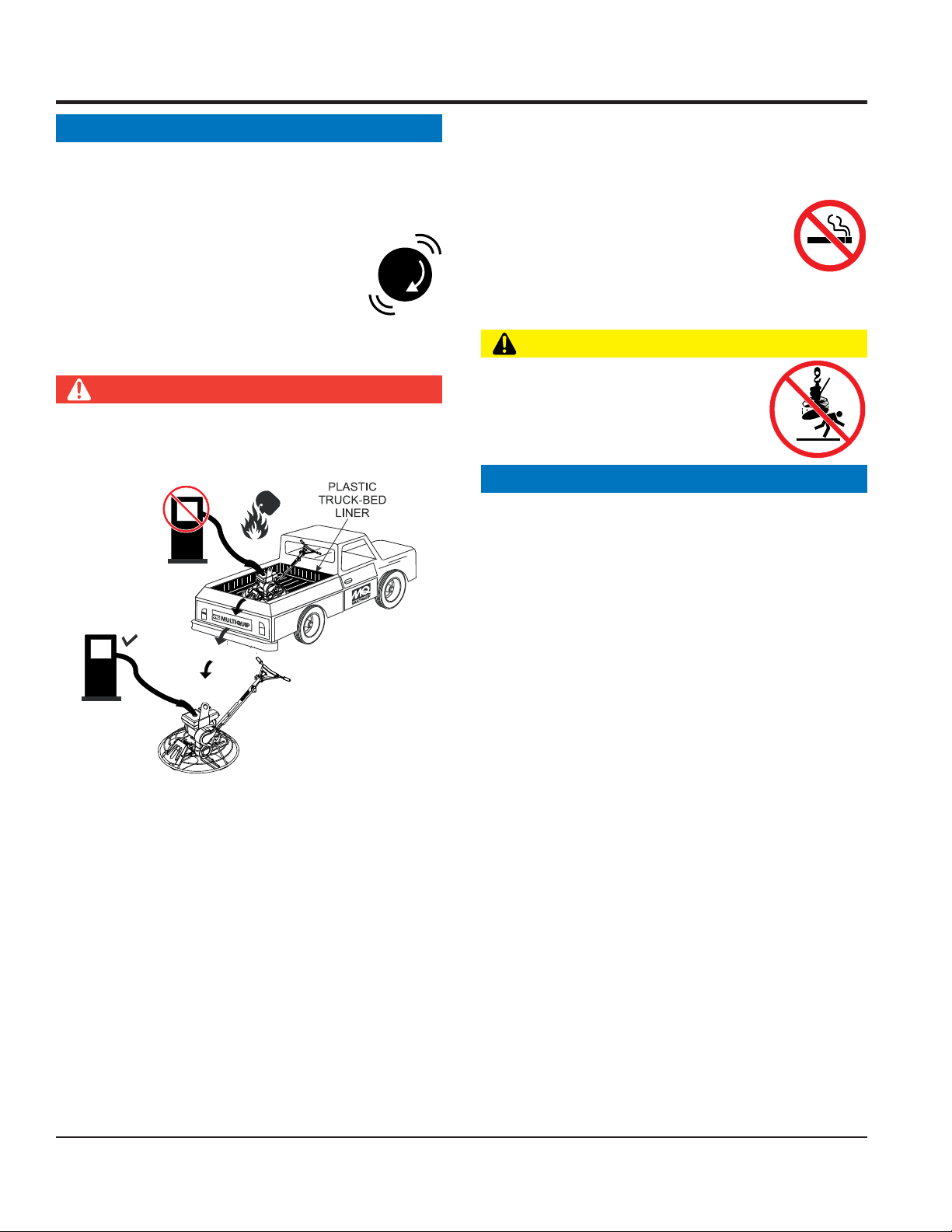
FUEL SAFETY
DANGER
DO NOT add fuel to equipment if it is placed inside truck
bed with plastic liner. Possibility exists of explosion or
fire due to static electricity.
FUEL
Store fuel in appropriate containers, in well-ventilated
areas and away from sparks and flames.
NEVER use fuel as a cleaning agent.
DO NOT smoke around or near the
equipment. Fire or explosion could result
from fuel vapors or if fuel is spilled on a
hot engine.
TRANSPORTING SAFETY
CAUTION
NEVER allow any person or animal to
stand underneath the equipment while
lifting.
NOTICE
Some walk-behind trowels can be lifted or moved by two
people utilizing lifting tubes or other special attachments.
Generally, however, they must be lifted using lifting bales
and cranes, hoists, or forklifts.
FUEL
DO NOT start the engine near spilled fuel or combustible
fluids. Fuel is extremely flammable and its vapors can
cause an explosion if ignited.
ALWAYS refuel in a well-ventilated area, away from
sparks and open flames.
ALWAYS use extreme caution when working with
flammable liquids.
DO NOT fill the fuel tank while the engine is running
or hot.
DO NOT overfill tank, since spilled fuel could ignite if it
comes into contact with hot engine parts or sparks from
the ignition system.
NEVER transport trowel with float pans attached unless
safety catches are used and are specifically cleared for
such transport by the manufacturer.
NEVER hoist the trowel more than three feet off the
ground with float pans attached.
Before lifting, make sure that the lifting bales are not
damaged.
Always make sure crane or lifting device has been
properly secured to the lifting bales of the equipment.
ALWAYS shutdown engine before transporting.
NEVER lift the equipment while the engine is running.
Tighten fuel tank cap securely and close fuel cock to
prevent fuel from spilling.
Use adequate lifting cable (wire or rope) of sufficient
strength.
DO NOT lift machine to unnecessary heights.
ALWAYS tie down equipment during transport by
securing the equipment with rope.
PAGE 10 — CA4HM WALK-BEHIND TROWEL — OPERATION MANUAL — REV. #3 (10/28/10)
Page 11

GENERATOR SAFETY
If using a generator to power trowel, refer to
applicable generator manual safety information
section.
ELECTRICAL SAFETY
DANGER
NEVER let power cords or cables lay in water.
NEVER use damaged or worn cables or cords when
connecting equipment to generator. Inspect for cuts in
the insulation.
NEVER grab or touch a live power
cord or cable with wet hands. The
possibility exists of electrical shock,
electrocution or death.
Make sure power cables are securely connected.
Incorrect connections may cause electrical shock and
damage to the trowel.
SAFETY INFORMATION
NOTICE
ALWAYS make certain that proper power or extension
cord has been selected for the job.
ENVIRONMENTAL SAFETY
NOTICE
Dispose of hazardous waste properly.
Examples of potentially hazardous waste
are used motor oil, fuel and fuel filters.
DO NOT use food or plastic containers to dispose of
hazardous waste.
DO NOT pour waste, oil or fuel directly onto the ground,
down a drain or into any water source.
CA4HM WALK-BEHIND TROWEL — OPERATION MANUAL — REV. #3 (10/28/10) — PAGE 11
Page 12

C
DIMENSIONS
D
B
A
Figure 1. CA4HM Trowel Dimensions
)elaBgnitfiL(thgieH-A).ni0.82(mm117
)reveLtnemegagnE(thgieH-B).ni52.63(mm129
htdiW-C).ni42(mm016
htgneL-D).t
thgieW).sbl521(gk75
thgieW&snoisnemiDleworTMH4AC.1elbaT
f80.5(m55.1
PAGE 12 — CA4HM WALK-BEHIND TROWEL — OPERATION MANUAL — REV. #3 (10/28/10)
Page 13

sedalBforebmuN4
retemaiDgniR ).mc16(.ni0.42
rotoR MPR031-07
htdiWhtaP ).mc16(.ni42
SPECIFICATIONS
snoitacificepSleworTMH4AC.2elbaT
1
)mrA/dnaH(noitarbiV
2
)dethgieW-A(erusserPdnuoS
)dethgieW-C,kaeP(erusserPdnuoS )C(Bd5.09
)dethgieW-A(leveLrewoPdnuoS )A(Bd79
NOTE:
1. The vibration level indicated is the maximum RMS (Root
Mean Square) value obtained at the handle grip while
operating the walk-behind trowel at full throttle on steel
plate with blades partially pitched.
2. Sound pressure is a weighted measure. It is measured at
the operator's ear position while the walk-behind trowel is
operating at full throttle on concrete in a manner most often
experienced in “
may vary depending upon the condition of the concrete.
Table 3. Engine Specifications
Model HONDA GX120K1QX2/GX120UT1QX2
Type 4-stroke, Overhead valve, Single Cylinder
Bore X Stroke
Displacement 7.3 cu. in. (119 cc)
2
s/m58.3
)A(Bd5.38
normal
2.4 in. X 1.7 in.
(60 mm x 42 mm)
” circumstances. Sound pressure
Max Output 3.9 H.P. (2.9 kW, 4.0 PS) at 3,600 R.P.M.
Engine
Dimension
(L x W x H)
Dry Net
Weight
Fuel Tank Capacity Approx. 0.66 U.S. Gallons (2.5 Liters)
Standard Idle Speed 1,400 +200/-150 R.P.M.
Fuel Unleaded Gasoline
Lube Oil Capacity 0.63 U.S. Quarts (0.60 Liters)
Speed Control Method Centrifugal Fly-weight Type
Starting Method Recoil Start
11.7 x 13.4 X 12.5 in.
(297 X 341 X 318 mm)
28.7 lbs. (13.0 Kg.)
CA4HM WALK-BEHIND TROWEL — OPERATION MANUAL — REV. #3 (10/28/10) — PAGE 13
Page 14

GENERAL INFORMATION
Intended Use
Operate the CA4HM Trowel, tools and components in
accordance with the manufacturer's instructions. Use of any
other tools for stated operation is considered contrary to
designated use. The risk of such use lies entirely with the user.
The manufacturer cannot be held liable for damages as a result
of misuse.
CA4HM Trowel Familiarization
This walk-behind trowel is designed for the
finishing
Take a walk around the trowel. Take notice of all the major
components (see Figure 2) like the engine, blades, Quick Pitch™
handle, clutch lever, etc. Check that there is always oil in the
engine.
Read
be found throughout this manual and on the trowel. Keep all
safety information in good, readable condition. Operators should
be well trained on the operation and maintenance of the trowel.
Before using your trowel, test it on a flat watered down section of
finished concrete that is free of any debris and other objects.
This trial test run will increase your confidence in using the trowel
and at the same time it will familiarize you with the trowel’s
controls. In addition you will understand how the trowel handles
under actual conditions.
Engine
This trowel is available with an 4 HP
Refer to the engine owner’s manual for instructions regarding
the operation and maintenance of your engine. Please contact
your nearest Multiquip Dealer for a replacement should the
original manual disappear or otherwise become unusable.
Drive System
Power is transferred from the engine to the gearbox input shaft
via a V-belt pulley drive system. The pulley engages using a
manual clutch. See Parts section of this manual.
of concrete slabs.
all the safety instructions carefully. Safety instructions will
HONDA
floating
gasoline engine.
and
Spider
The vertical output shaft of the gearbox connects to a cast hub
called the
that are used for attachment of blades or other accessories.
Remember as the gearbox output shaft rotates so does the spider
assembly.
Guard Ring
This unit is equipped with a special rotating guard ring. It is
designed to allow the operator to run the machine alongside
walls, pipes, and obstructions without marring the surface.
Blades
The blades of the trowel finish the concrete as they are rotated
around the surface. This trowel comes equipped with four
combination
spaced in a radial pattern and attached to vertical rotating
shaft by means of a
Manual Clutch
In the event of a trowel runaway condition (operator releases
the handle), a
the trowel to a halt.
CAUTION
NEVER attempt to
the assistance of another person to help lift the trowel .
Training
For proper training, please use the “TRAINING CHECKLIST”
located in the front of this manual (Page 8). This checklist will
provide an outline for an experienced operator to provide training
to a new operator
spider
. The spider has 4 arms that extend outward
(8 in./203mm wide) blades per rotor equally
spider assembly.
manual clutch
CAUTIONCAUTION
CAUTION
CAUTIONCAUTION
lift
the trowel by yourself. ALWAYS get
will stop the engine and bring
Gearbox
gearbox
The
spider
to the
of the trowel and is equipped with two shafts (input and output).
is located beneath the engine and transfers power
assembly. The gearbox controls the rotational speed
PAGE 14 — CA4HM WALK-BEHIND TROWEL — OPERATION MANUAL — REV. #3 (10/28/10)
Page 15

Figure 2. Controls and Components
6
COMPONENTS
1
3
2
11
10
5
4
9
7
Figures 2 shows the location of the basic controls or components,
CA4HM TROWEL
for the
. Listed below is a brief explanation of
each control or component
1. Quick Pitch™ Control Handle – To adjust the pitch of
the blades, grasp the handle then squeeze and either move
the handle forward or backward to achieve the desired
blade pitch.
2. Throttle Control Lever – Controls the speed of the engine.
Move the hand lever towards the operator to increase
engine speed (high), away from the operator to decrease
engine speed (low).
3. Hand Grip/Handle Bar – When operating the trowel, place
both hands on each grip to maneuver the trowel. Replace
hand grips when they become worn or damaged.
4. Clutch Lever - Clutch engagement lever. When this lever
is engaged, the blades will begin to rotate.
7. Trowel Arm – NEVER operate the trowel with a bent, broken
or out of adjustment trowel arm. If the blades show uneven
wear patterns or some blades wear out faster than others,
the trowel arm may need to be replaced.
8. Blades – This trowel is equipped with special combination
blades. Designed specifically for edging. In addition float
discs can be attached to the trowel arms that will allow the
trowel to float on "
9. V-Belt Cover – Remove this cover to gain access to the Vbelt. NEVER operate the trowel with this cover removed.
10. T-Handle Release Knob – Turn this handle counterclockwise to release the upper handle and place in either
down position or operate position. Turn handle clockwise
to lock upper handle in place.
11. Engine – This trowel uses a Honda GX120 4 H.P. gasoline
engine.
8
wet
" concrete.
5. Clutch Lever Retainer- Assists the operator in holding
down the clutch lever.
6. Rotating Guard Ring- NEVER put hands or feet inside
guard ring. NEVER attempt to llift trowel by the guard ring.
CA4HM WALK-BEHIND TROWEL — OPERATION MANUAL — REV. #3 (10/28/10) — PAGE 15
Page 16

BASIC ENGINE
Figure 3. Honda GX120K1QX2/UT1QX2 Engine Controls and Components
INITIAL SERVICING
The engine (Figure 3) must be checked for proper lubrication and
filled with fuel prior to operation. Refer to the manufacturer's engine
manual for instructions & details of operation and servicing. The
engine shown above is a HONDA engine, operation for other
types of engines may vary somewhat.
1. Fuel Filler Cap – Remove this cap to add unleaded
gasoline to the fuel tank. Make sure cap is tightened
securely. DO NOT over fill.
5. Fuel Valve Lever – OPEN to let fuel flow, CLOSE to stop
the flow of fuel.
6. Choke Lever – Used in the starting of a cold engine, or in
cold weather conditions. The choke enriches the fuel
mixture.
7. Air Cleaner – Prevents dirt and other debris from entering
the fuel system. Remove wing-nut on top of air filter
cannister to gain access to filter element.
NOTICE
DANGER
Adding fuel to the tank should be done only
when the engine is stopped and has had an
opportunity to cool down. In the event of a fuel
spill, DO NOT attempt to start the engine until
the fuel residue has been completely wiped
up, and the area surrounding the engine is
dry.
2. Throttle Lever – Used to adjust engine RPM speed (lever
SLOW
advanced forward
FAST
).
3. Engine ON/OFF Switch –
OFF
starting,
4. Recoil Starter (pull rope) – Manual-starting method. Pull
the starter grip until resistance is felt, then pull briskly and
smoothly.
position stops engine operation.
, lever back toward operator
ON
position permits engine
Operating the engine without an air filter, with a damaged
air filter, or a filter in need of replacement will allow dirt to
enter the engine, causing rapid engine wear.
8. Spark Plug – Provides spark to the ignition system. Set
spark plug gap according to engine manufacturer's
instructions. Clean spark plug once a week.
9. Muffler – Used to reduce noise and emissions.
10. Fuel Tank – Holds unleaded gasoline. For additional
information refer to engine owner's manual.
11. Oil Drain Plug – Remove this plug to remove oil from the
engine's crankcase.
12. Dipstick/Oil Filler Cap – Remove this cap to determine if
the engine oil is low. Add oil through this filler port as
recommended in Table 3.
PAGE 16 — CA4HM WALK-BEHIND TROWEL — OPERATION MANUAL — REV. #3 (10/28/10)
Page 17

ASSEMBLY
Quick Pitch™ Handle Assembly
The CA4HM TROWEL is equipped with a folding upper handle
(Figure 4). It was assembled at the factory and shipped in its
folded or stow position. You will need to unfold and adjust the
trowel handle to the upright position prior to operation.
NOTICE
Considerable force may be required when moving
the Quick Pitch
™ handle forward or backward.
Unfolding the Trowel for Operation
1. Make sure that the Quick Pitch™
attached to the upper handle bar and the pitch control cable
has slack. Remove the
on the top side of the upper handle bar, by rotating the
knob counter-clockwise. Move the Quick Pitch™
toward's the operator's position and unfold the upper
handle bar away from the engine into the
Re-insert the swing bolt so that it fits through the slot in the
hinge plate. Turn the T-handle knob counter-clockwise
securely to hold upper handle bar in place.
CAUTION
DO NOT operate unless T-Handle Knob is securely in place.
2. When folding the handle assembly, remember to move the
Quick Pitch™ handle forward first to avoid stretching
the throttle cable.
T-handle knob
handle
has been
from the swing bolt
handle
upright
position.
FOLDED
POSITION
Quick Pitch Handle
should be forward
when handle is in
folded position.
OPERATIONAL
POSITION
UPPER
HANDLE
T-HANDLE
KNOB
Figure 4. Trowel Folded and Operational Positions
CA4HM WALK-BEHIND TROWEL — OPERATION MANUAL — REV. #3 (10/28/10) — PAGE 17
Page 18

CAUTION
ALWAYS wear approved eye and
hearing protection before operating the
trowel.
NEVER place hands or feet inside the
guard rings while the engine is running.
ALWAYS shut the engine down before
performing any kind of maintenance
service on the trowel.
INSPECTION
Figure 5. Engine Oil Dipstick (Removal)
3. Insert and remove the dipstick without screwing it into the filler
neck. Check the oil level shown on the dipstick.
Before Starting
1. Read safety instructions at the beginning of manual.
2. Clean the trowel, removing dirt and dust, particularly the
engine cooling air inlet, carburetor and air cleaner.
3. Check the air filter for dirt and dust. If air filter is dirty, replace
air filter with a new one as required.
4. Check carburetor for external dirt and dust. Clean with dry
compressed air.
5. Check fastening nuts and bolts for tightness.
Engine Oil Check
1. To check the engine oil level, place the trowel on secure
level ground with the engine stopped.
2. Remove the filler dipstick from the engine oil filler hole
(Figure 5) and wipe clean.
4. If the oil level is low (Figure 6), fill to the edge of the oil filler
hole with the recommended oil type (Table 3). Maximum oil
capacity is 0.48 quarts (.45 liters).
NOTICE
Refer to manufacturer's engine manual for specific
servicing instructions.
Figure 6. Engine Oil Dipstick (Oil Level)
epyTliO.4elbaT
nosaeS erutarepmeT epyTliO
remmuS rehgiHroC°52 03-W01EAS
llaF/gnirpS C°01~C°52 02/03-W01EAS
retniW rewoLroC°0 01-W01EAS
PAGE 18 — CA4HM WALK-BEHIND TROWEL — OPERATION MANUAL — REV. #3 (10/28/10)
Page 19

INSPECTION
DANGER
EXPLOSIVE FUEL!
Motor fuels are highly flammable and can
be dangerous if mishandled. DO NOT
smoke while refueling. DO NOT attempt to
hot!
refuel the trowel if the engine is
running
Fuel Check
1. Remove the gasoline cap located on top of fuel tank.
2. Visually inspect to see if fuel level is low. If fuel is low, replenish
with unleaded fuel.
3. When refueling, be sure to use a strainer for filtration. DO
NOT top-off fuel. Wipe up any spilled fuel.
Gearbox Oil
1. Determine if the
plug located on the side of the gearbox. This plug will be
marked by the "
level of the lubrication oil should be to the bottom of the fill
plug.
.
gearbox
check
oil is low by removing the oil
" decal. See Figure 7. The correct
or
V-Belt Check
A worn or damaged V-belt can adversely affect the performance
of the trowel. If a V-belt is defective or worn simply replace the Vbelt as outlined in the maintenance section of this manual.
Belt Guard Check
Check for damage, loose or missing hardware.
Blade Check
Check for worn or damaged blades. Check to see if one blade is
worn out while the others look new. If this is the case there could
be a blade pitch problem. Refer to the maintenance section of
this manual for blade pitch adjustment procedure. Replace any
worn blades.
Hand Clutch
This finisher model is equipped with a
The unit automatically stops rotating when the clutch lever is
released. Clutch operation should be tested each time the machine
is started.
CAUTION
Disconnect the spark plug wire from the spark plug and
secure away from the engine before performing
maintenance or adjustments on the machine.
hand operated clutch
.
DO NOT let the machine sit unused with the engine at high speed
for an extended period of time. It will cause premature belt wear
or may destroy the belt. Always set the engine speed to idle when
the hand clutch is disengaged.
WARNING
NEVER attempt to override the manual clutch by using
tape or other means to hold down the clutch lever. Doing so
may cause SEVERE INJURY.
Figure 7. Gearbox
2. If lubrication oil begins to seep out as the drain plug is
being removed, then it can be assumed that the gearbox
has a sufficient amount of oil.
3. If lubrication oil does not seep out as the drain plug is
being removed, fill with type ISO 680 (P/N 10139) gearbox
lubricant oil until the oil filler hole overflows.
CA4HM WALK-BEHIND TROWEL — OPERATION MANUAL — REV. #3 (10/28/10) — PAGE 19
Page 20

This section is intended to assist the operator with the initial
start-up of the walk-behind trowel. It is extremely important that
this section be read carefully before attempting to use the trowel
in the field.
DO NOT use your trowel until this section is thoroughly
understood
Lifting the Trowel Onto a Slab
Extra care should be taken when lifting the trowel off the ground.
Serious damage to the machine or personal injury could be
caused by dropping a trowel.
3. Place the
if starting a
WARNING
NEVER attempt to lift this machine alone. NEVER lift the
trowel by the guard ring as it may rotate and cause injury.
ALWAYS make certain the folding handle is secure and use
only the manufaturer's approved lifting points. The trowel
may be lifted at the center lifting bale by crane or other lifting
device of adequate capacity.
OPERATION
Figure 9. Throttle Lever (Idle Position)
choke lever
cold
(Figure 10) in the "
engine.
CLOSED
" position
CAUTION
DO NOT attempt to operate the trowel until the Safety,
General Information and Inspection sections of this manual
have been read and thoroughly understood.
Starting the Engine
1. Place the engine
position.
fuel valve lever
(Figure 8) to the "ON"
4. Place the
starting a
5. Place the
position.
choke lever
Figure 11. Engine Choke Lever (Open)
engine ON/OFF switch
Figure 10. Engine Choke Lever
(Figure 11) in the "
warm engine
or the
temperature is warm.
OPEN
" position if
(Figure 12) in the "
ON
"
Figure 8. Engine Fuel Valve Lever
2. Place the trowel's
position.
throttle lever
PAGE 20 — CA4HM WALK-BEHIND TROWEL — OPERATION MANUAL — REV. #3 (10/28/10)
(Figure 9) to the "IDLE"
Figure 12. Engine ON/OFF Switch
Page 21

OPERATION
6. Grasp the starter grip (Figure 13) and slowly pull it out. The
resistance becomes the hardest at a certain position, corresponding to the compression point. Pull the starter grip briskly
and smoothly for starting.
Figure 13. Starter Grip
7. If the engine has started, slowly return the choke lever
(Figure 11) to the
repeat steps 1 through 6.
8. Before the trowel is placed into operation, run the engine for
several minutes. Check for fuel leaks, and noises that would
associate with a loose V-belt cover or component.
OPEN
position. If the engine has not started
2. After the engine
“OFF” position (Figure 15).
Figure 15. Engine ON/OFF Switch (OFF Position)
3. Close the
valve lever to the OFF position.
cools
, turn the engine start/stop switch to the
fuel shut- off valve
(Figure 16) by moving the fuel
To begin troweling, move the throttle lever (Figure 14) toward
9.
the "
FAST
" position.
Figure 14. Throttle Lever (Run Position)
Stopping The Engine
1. Move the throttle lever to the IDLE or SLOW position (Figure
14) and run the engine for three minutes at low speed.
Figure 16. Fuel Valve Lever (OFF Position)
CA4HM WALK-BEHIND TROWEL — OPERATION MANUAL — REV. #3 (10/28/10) — PAGE 21
Page 22

OPERATION
The following steps are intended as a basic guide to machine
operation, and are not to be considered a complete guide to
concrete finishing. We suggest that all operators (experienced
and novice) read “
Slabs on Grade
Concrete Institute, Detroit, Michigan
” published by the
American
. Read the “Training”
2. To maneuver the trowel, gently lift up on or press down on the
main trowel handle. To move the machine to the operator’s
left,
down
section of this manual for more information.
Pitching The Blades - Quick Pitch Handle
1. To pitch the blades upwards using the
handle
, (Figure 17) simply squeeze the trigger lock
"Quick Pitch
™"
and pull the handle towards the operator. Pushing the
handle towards the engine will cause the blades to lay
flat.
BLADE PITCH
ADJUSTMENT
TRIGGER
QUICK PITCH
HANDLE
TM
3. The best method for finishing concrete is to slowly walk
backwards (Figure 19) with the trowel, guiding the trowel
INCREASE
BLADE PITCH
DECREASE
BLADE PITCH
(COMPRESSES SPRING
INSIDE HANDLE TUBE)
from side to side. This will cover all footprints on wet concrete.
4. Remember that if you let go of the trowel, just step away and
let the trowel come to a complete stop before trying to recover
the trowel.
lift up
on the handle, to move machine to the right,
on the handle.
Figure 18. Hand Clutch Lever
push
Figure 17. Quick Pitch™ Handle
Maneuvering the Trowel
1. Get into the operator’s position behind the handle. With a
secure foothold and a firm grasp on the handles slowly
increase the engine speed until the desired blade speed is
obtained.
Set engine speed with the throttle, then pull on the hand
clutch lever to start the blades turning. Adjust the blade speed
after the hand clutch is fully engaged.
5. Check the manual clutch occasionally for proper operation.
Checking operation of the manual clutch at the beginning of
operation and periodically serves as a safety check verification.
PAGE 22 — CA4HM WALK-BEHIND TROWEL — OPERATION MANUAL — REV. #3 (10/28/10)
Page 23

OPERATION
Figure 19 below illustrates a typical walk-behind trowel
application. Practice maneuvering the trowel. The trick is to let
the trowel do the work.
Continue to practice maneuvering the trowel. Try to practice as if
you were finishing a slab of concrete. Practice edging and
covering a large area. Remember a good finishing technique is
to work backwards. Be careful when moving backwards so that
hazards can be avoided. The best way to get accustomed to the
trowel is repeated use.
Figure 19. Maneuvering The Trowel
CAUTION
NEVER place your
while starting or operating this equipment.
feet
or
hands
inside the guard rings
CA4HM WALK-BEHIND TROWEL — OPERATION MANUAL — REV. #3 (10/28/10) — PAGE 23
CAUTION
ALWAYS keep clear of
operating this equipment.
rotating
or
moving
parts while
Page 24

OPTIONS
Blades
NOTICE
Blades should be changed when they fail to finish
concrete in a satisfactory manner.
Blades are a vital part of finishing concrete. This finisher has been
designed to finish concrete and is built to stringent quality standards
out of the finest trowel steel. If you need replacement blades,
consult your parts list in this manual for part numbers and order
them from your Multiquip parts dealer or importer.
Combo Blades
This trowel was equipped with
blades as original equipment. These blades have been designed
for optimum performance in both the floating and finishing of
concrete. These blades are versatile and should take care of most
troweling needs.
combination type
(Figure 20)
Optional Float Discs (Pans)
These round discs (Figure 21) attach to the spiders and allow the
machine to “
floating and easy movement from wet to dry areas. They are also
very effective in embedding large aggregates and surface
hardeners.
float
” on “
wet
” concrete. The disc design allows early
Figure 21. Float Disk (Pan)
Figure 20. Combination Blade
PAGE 24 — CA4HM WALK-BEHIND TROWEL — OPERATION MANUAL — REV. #3 (10/28/10)
Page 25

MAINTENANCE
NOTICE
See the engine manual supplied with your machine for
appropriate engine maintenance schedule and
troubleshooting guide for problems. At the front of the book
there is a “Daily Pre-Operation Checklist ”. Make copies
of this checklist and use it on a daily basis.
CAUTION
ALWAYS allow the engine to cool before
servicing. NEVER attempt any maintenance
work on a hot
engine.
Trowel Arm Adjustment Procedure
NOTICE
The following procedure should be followed to adjust trowel
arms when it becomes apparent that the trowel is finishing
poorly or in need of routine maintenance.
A
level
Any unlevel
will give an incorrect perception of adjustment. Ideally, a 5" x 5"
(127mm x 127mm), 0.75 inch (19 mm) thick
be used for testing.
1. To determine which blades need adjustment, place the
trowel in the test area (0.75 inch [19 mm] thick plate) and look
for the following conditions:
■
CAUTION
Disconnect the spark plug wire from the spark plug and
secure away from the engine before performing
maintenance or adjustments on the machine.
■
MAINTENANCE SCHEDULE
Daily (8-10 Hours)
1. Check the oil level in the engine crankcase and gear box,
fill as necessary.
2. Check V-belt.
Figure 22 below illustrates "
Check to see that adjustment bolt is barely touching (0.10" max.
clearance) lower wear plate. All alignment bolts should be spaced
the same distance from the lower wear plate.
, clean area to test the trowel prior to and after is essential.
spots
in the floor or debris under the trowel blades
flat
steel plate should
Pitch the blades as flat as possible and look at the
adjustment bolts
with the
that one of them is not making contact, some adjustment
will be necessary.
Is the machine wearing out blades unevenly (i.e. one
blade is completely worn out while the others look new)?
lower wear plate
. They should all just make contact
on the spider. If you can see
worn spider or bent trowel arms
".
Weekly (50-60 Hours)
1. Relube arms, thrust collar and clutch
2. Replace blades if necessary.
3. Check and clean or replace the engine air filter as
necessary.
4. Replace engine oil and filter as necessary, see engine
manual.
Monthly (200-300 Hours)
1. Remove, clean, reinstall and relube the arms and thrust
collar. Adjust the blade arms.
2. Remove, clean, reinstall clutch.
Yearly (2000-2500 Hours)
1. Check and replace if necessary the arm bushings, thrust
collar bushings and shaft seals.
2. Check pitch control cables for wear.
3. Adjust blade speed.
Figure 23 below illustrates the "
plate (as shipped from the factory).
CA4HM WALK-BEHIND TROWEL — OPERATION MANUAL — REV. #3 (10/28/10) — PAGE 25
Figure 22 Worn Spider Plate
correct alignment
Figure 23. Correct Spider Plate Alignment
" for a spider
Page 26

MAINTENANCE
2. Start engine, and bring trowel blades up to full speed and look
for the following conditions:
■
Does the trowel have a perceived rolling or bouncing
motion when in use?
■
Look at the trowel while it is running, does the guard
ring “rock up and down” relative to the ground?
Spider Removal
1. Once it is determined that an adjustment is required, remove
the spider assembly from the gearbox shaft as follows:
a. Remove the zerk fitting and allen head screw desig-
nated by the letter "S" (Figure 24). In addition, on the
opposite side of the spider block there is another zerk
fitting and allen head screw, remove both of these
components.
b. Lift the upper trowel assembly off the spider assembly.
Trowel Arm Removal
1. Remove the two remaining zerk fittings and allen head
screws from the spider assembly (Figure 25).
A slight tap with a rubber mallet may be necessary to
dislodge the spider from the main shaft of the gearbox.
Figure 25. Trowel Arms Removal
Trowel Blade Removal
CAUTION
Disconnect the spark plug wire from the spark plug and
secure away from the engine before performing
maintenance or adjustments on the machine.
1. Remove the trowel blades from the trowel arm by removing
the two hex head bolts (Figure 26) from the trowel arm. Set
blades aside.
Figure 26. Trowel Blades
Figure 24. Spider/Gearbox Removal
Wire brush
2.
trowel arm. Repeat this for the remaining three arms.
any build-up of concrete from all six sides of the
PAGE 26 — CA4HM WALK-BEHIND TROWEL — OPERATION MANUAL — REV. #3 (10/28/10)
Page 27

MAINTENANCE
Checking Trowel Arm Straightness
Trowel arms can be damaged by rough handling, (such as dropping
the trowel on the pad), or by striking exposed plumbing, forms, or
rebar while in operation. A bent trowel arm will not allow the trowel
to operate in a smooth fluid rotation. If bent trowel arms are suspect,
check for flatness as follows, refer to Figures 27 and 28:
1 Trowel Arm Round Shaft Section
2 Trowel Arm Hexagonal (Hex) Shaft Section
3 Lever Mounting Slot (Left Arm Shown)
4 Roll Pin Hole
5 Blade Attachment Bolt Hole (One of Three)
6 Flat of Hexagonal Shaft (Top of Arm)
3. Next, check the clearance between the round shaft and the
test surface as one of the flat hex sections of the arm rests on
the test surface. Rotate the arm to each of the flat hex sections
and check the clearance of the round shaft. Use a feeler
gauge of .005" (0.127 mm). Each section should have the
same clearance
and the test surface.
4. If the trowel arm is found to be
trowel arm.
Trowel Arm Adjustment
Shown in (Figure 31) is the adjustment fixture with a trowel arm
inserted. As each trowel arm is locked into the fixture, the arm bolt
is adjusted to where it contacts a stop on the fixture. This will
consistently adjust all of the trowel arms, keeping the finisher as
flat and evenly pitched as possible.
1. Locate the trowel arm adjustment tool P/N 9177.
between the round of the trowel arm shaft
uneven
2
or
bent
, replace the
Figure 27. Trowel Arm
1. Use a thick steel plate, granite slab or any surface which is
true
and
flat
, to check all
flatness.
2. Check each of the six sides of the trowel arm (hex section).
A feeler gauge of .004" (0.10 mm) should not pass between
the flat of the trowel arm and the test surface along its length
on the test surface. (Figure 28 item 3) .
1 Trowel Arm
2 Flat Test Surface
3 Feeler Gauge (.004 in. / 0.10 mm)
4 Feeler Gauge (.005 in. / 0.127 mm))
Figure 28. Checking Trowel Arm Flatness
six sides
of each trowel arm for
Figure 29. Trowel Arm Adjustment Tool Side View
2. Ensure the fixture arm is in the proper setting (up or down) for
your trowel arm rotation as shown in Figure 30.
NOTICE
Arms with clockwise blade rotation use the fixture arm in the
UP position (A in Figure 30). Arms with COUNTER CLOCKWISE blade rotation use the fixture with the fixture arm in the
DOWN position. (B in Figure 30).
1
1 Adjustment Bolt
2 "Distance"
3 Locking Nut
4 Fixture Arm
3
4
SIDE VIEW
CA4HM WALK-BEHIND TROWEL — OPERATION MANUAL — REV. #3 (10/28/10) — PAGE 27
Page 28

4. Use an allen wrench to tighten the locking bolts securing the
trowel arm in place.
5. Adjust the bolt "distance" shown in Figure 29 to match one
of the arms. For a CA4HM trowel arm, this distance will be
approximately 5/16" (7.938mm). The other arms will be
adjusted to match this distance.
6. Loosen the locking nut on the trowel arm lever, then turn the
trowel arm adjusting bolt until it barely touches (.010") the
fixture adjusting bolt.
7. Once the correct adjustment is made, tighten the lock nut on
the trowel arm to lock in place.
8. Loosen locking nuts on the adjustment fixture, and remove
Figure 30. Trowel Arm Adjustment Setup
3. Unscrew the locking bolts on the adjustment tool and place
the trowel arm into the fixture channel as shown in Figure 31
A thin shim may be required to cover the blade holes on the
trowel arm. Make sure to align the trowel adjustment bolt with
the fixture adjustment bolt.
trowel arm.
9. Repeat steps for the remaining trowel arms.
Re-Assembly
1. Clean and examine the upper/lower wear plates and thrust
collar. Examine the entire spider assembly. Wire brush any
concrete or rust build-up. If any of the spider components are
found to be damaged or out of round, replace them.
MAINTENANCE
2. Make sure that the bronze trowel arm bushing is not damage
3. Reinstall bronze bushing onto trowel arm.
4. Repeat steps 2 -3 for each trowel arm.
5. Make sure that the spring tensioner is in the correct position
1 Arm
2 Trowel Arm Lever
3 Fixture Arm
4 Adjustment Bolt
5 Distance = .010 Inch
6 Adjustment Bolt
7 Trowel Arm Adjustment Fixture
8 Locking Bolts
9 Shim
Figure 31. Trowel Arm Adjustment Fixture Components
6. Insert all trowel arms with levers into spider plate (with bronze
7. Lock trowel arms in place by tightening the hex head bolt with
8. Re-install the blades onto the trowel arms.
9. Install stabilizer ring onto spider assembly.
10. Lubricate all grease points (zerk fittings) with premium
or out of round. Clean the bushing if necessary. If the bronze
bushing is damaged or worn, replace it.
to exert tension on the trowel arm.
bushing already installed) using care to align grease hole on
bronze bushing with grease hole fitting on spider plate.
zerk grease fitting and jam nut.
Lithum 12"
"
consistency.
based grease, conforming to NLG1 Grade #2
PAGE 28 — CA4HM WALK-BEHIND TROWEL — OPERATION MANUAL — REV. #3 (10/28/10)
Page 29

MAINTENANCE
Changing a Blade
We recommend that
. The machine may wobble or bounce if only some of the
time
blades are changed at one time.
1. Place the machine on a flat, level surface. Adjust the blade
pitch control to make the blades as flat as possible. Note the
blade orientation on the trowel arm.
all the blades be changed at the
same
NOTICE
Before removing the blades, please note the orientation
of the blade on the trowel arm.
1. Remove the two bolts and lock washers that secure the blade
to the trowel arm. Remove the blade.
2. Using a wire brush, scrape all concrete particles and foreign
debris from the trowel arm.
3. Install the new trowel blade onto the trowel arm. Make sure
blade is installed correctly, maintaining the proper orientation for direction of rotation
.
NOTICE
Check the manual clutch occasionally for proper operation.
Checking operation of the manual clutch at the beginning of
operation and periodically serves as a safety check verification.
Hand Clutch Disengagement
1. Start the trowel as outlined in the "
this manual. Move the throttle lever so that the engine is
running about 1/4 to 1/3 of full speed.
2. Grip the trowel handle firmly and carefully engage the clutch
by squeezing the clutch lever toward the handle with your left
hand. After the trowel is stabilized and you feel comfortable
with its operation, use your right hand to adjust the housing
adjustment nut.
3. Rotating the nut so that it backs out of the lever housing
increases the engagement and also the squeezing force
required to keep it engaged.
Initial Start-up
" section in
4. Reinstall
blade to the trowel arm. Tighten both bolts securely.
5. Repeat steps 1 - 4 for all remaining blades.
Hand Clutch Adjustment
This trowel is equipped with a hand-operated clutch that is a belttightener type clutch. It operates by removing
which then transmits power from the engine to the gearbox.
There are two reasons to adjust the hand clutch: 1) operator
comfort; 2) initial belt stretch and break-in.
The easiest and most simple adjustment is to adjust the clutch
cable housing using the adjustment nut (Figure 32) located on the
clutch lever. Rotating the nut provides either more or less
(depending upon the direction of rotation) clutch engagement.
the two bolts and lock washers that secure the
slack
in the V-belt
Too much squeezing force may cause premature hand
fatigue. Too little squeezing force may cause belt slippage
and premature belt wear. Each operator should experiment
with the adjustment to get the optimum combination of
squeeze force and belt grip.
4. After initial break-in (approximately 8 hours) the above
procedure should be repeated to attain optimum operator
comfort and belt wear.
5. After considerable belt wear, the adjustments mentioned
above may have a little or no effect on clutch engagement. If
this is the case, the belt should be replaced.
WARNING
NEVER attempt to override the manual clutch by using
tape or other means to hold down the clutch lever. Doing so
may cause SEVERE INJURY.
Figure 32. Trowel Arm Adjustment Tool
CA4HM WALK-BEHIND TROWEL — OPERATION MANUAL — REV. #3 (10/28/10) — PAGE 29
Page 30

MAINTENANCE
Installing Pans Onto Finisher Blades
WARNING
ALWAYS install pans either on the work area or on an area
that is next to and level with the work area. DO NOT lift the
trowel when the pans are attached.
Refer to Figure 33 when installing pans onto finisher blades.
1. Lift trowel just enough to slide pan under blades. Lower
finisher onto pan with blades (item #1) adjacent to Z-Clips
(item #4).
2. Rotate blades into position under Z-Clips. Ensure that the
blades are rotated in the direction of travel when the machine
is in operation or use the engine to rotate the blades into
position.
3. Attach the blade tie-downs (item #3) to the far side of the ZClip brackets (item #4) with tie-down knobs (item #2) as
shown in figure 33.
4. Check to make certain that the blade edges are secured
under the Z-Clips and the tie-downs are secured completely
over the edges of the blade bar before the machine is put back
into operation.
Decommissioning Trowel/Components
Decommissioning is a controlled process used to safely retire a
piece of equipment that is no longer serviceable. If the equipment
poses an
or damage or is no longer cost effective to maintain, (beyond lifecycle reliability) and is to be decommissioned,
dismantlement), the following procedure must take place:
unacceptable and unrepairable safety risk due to wear
(demolition and
2
3
1. Drain all fluids completely. These may include oil, gasoline,
hydraulic oil and antifreeze. Dispose of properly in accordance with local and governmental regulations. Never pour
on ground or dump down drains or
2. The remainder can be brought to a salvage yard or metal
reclamation facility for further dismantling.
sewers.
1
4
1 BLADE ASSEMBLY
2 KNOB, TIE DOWN Z-CLIP PANS
3 TIED OWN, BLADE
4 Z-CLIP, PAN
Figure 33. Pan Installation
PAGE 30 — CA4HM WALK-BEHIND TROWEL — OPERATION MANUAL — REV. #3 (10/28/10)
Page 31

Symptom Possible Problem Solution
Engine running rough or not at all.
Trowel bounces, rolls concrete, or makes
uneven swirls in concrete.
TROUBLESHOOTING
Troubleshooting (Walk-Behind Trowel)
Engine ON/OFF Switch in "OFF" position
or malfunctioning?
Centrifugal stop switch malfunction? (if
applicable)
Fuel?
Ignition?
Loose wire connections Check wiring. Replace or repair as necessary.
Bad contacts in ON/OFF switch? Replace ON/OFF switch.
Blades?
Pitch adjustment?
Bent trowel arms?
Spider?
Thrust collar?
Thrust collar bushing?
Thrust bearing worn?
Make sure that the Engine ON/OFF Switch is ON
or replace switch if necessary.
Make sure that the centrifugal stop switch is
functioning when the operator is seated. Replace
switch if necessary.
Look at the fuel system. Make sure there is fuel
being supplied to the engine. Check to ensure that
the fuel filter is not clogged.
Check to ensure that the ignition switch has power
and is functioning correctly.
Make certain blades are in good condition, not
excessively worn. Finish blades should measure
no less than 2"" (50mm) from the blade bar to
the trailing edge, combo blades should measure
no less that 3.5"" (89mm). Trailing edge of blade
should be straight and parallel to the blade bar.
Check that all blades are set at the same
pitch angle as measured at the spider. A field
adjustment tool is available for height adjustment
of the trowel arms. (Contact Parts Dept.)
Check the spider assembly for bent trowel arms.
If one of the arms is even slightly bent, replace it
immediately.
Check fit of arms in spider. This can be done by
moving the trowel arms up and down. If there is
more than 1/8 inch (3.2 mm) of travel at the tip of
the arm, the spider and arms should be replaced.
Check the flatness of the thrust collar by rotating
it on the spider. If it varies by more than 0.02 inch
(0.5 mm) replace the thrust collar.
Check the thrust collar by rocking it on the spider.
If it can tilt more than 3/32 inch (2.4 mm) - as
measured at the thrust collar O.D., replace the
thrust collar.
Check the thrust bearing to see that it is spinning
freely. Replace if necessary.
CA4HM WALK-BEHIND TROWEL — OPERATION MANUAL — REV. #3 (10/28/10) — PAGE 31
Page 32

Symptom Possible Problem Solution
Machine has a perceptible rolling motion
while running.
Clutch slipping or sluggish response to
engine speed change.
Trowel blades do not rotate.
(Electric Models)
TROUBLESHOOTING
Troubleshooting (Walk-Behind Trowel) - continued
The main output shaft of the gearbox
assembly should be checked for straightness.
Main shaft?
Yo k e ?
Blade Pitch?
Worn V-belts? Replace V-belt.
Hand clutch out of adjustment?
Worn or defective hand clutch parts? Replace parts as necessary.
Worn bearings in gearbox?
Worn or broken gears in gearbox?
Incorrect or no voltage being supplied to
electric motor?
Power to electric motor?
Broken V-belt? Replace V-belt.
Defective ON/OFF switch?
Defective electric motor? Replace electric motor.
The main shaft must run straight and cannot
be more than 0.003"" (0.08 mm) out of round
at the spider attachment point.
Check to make sure that both fingers of the
yoke press evenly on the wear cap. Replace
yoke as necessary.
Check to ensure that each blade is adjusted
to have the same pitch as all other blades.
Adjust per maintenance section in manual.
Adjust per instructions in maintenance
section of this manual.
Rotate input shaft by hand. If shaft rotates
with difficulty, check the input and output
shaft bearings. Replace as necessary.
Verify that the gearbox shaft rotates when
the input shaft is rotated. Replace both the
worm and worm gear as a set.
Check that the electric motor has the correct
supply voltage.
Inspect power source and extension cord.
Push reset button on electric motor. Make
sure correct voltage is being supplied to
motor.
Check and replace ON/OFF switch if
necessary.
PAGE 32 — CA4HM WALK-BEHIND TROWEL — OPERATION MANUAL — REV. #3 (10/28/10)
Page 33

Symptom Possible Problem Solution
Difficult to start, fuel is available, but no spark
at spark plug.
Difficult to start, fuel is available, and spark is
present at the spark plug.
Difficult to start, fuel is available, spark is
present and compression is normal.
Difficult to start, fuel is available, spark is
present and compression is low.
No fuel present at carburetor.
TROUBLESHOOTING
Troubleshooting (Engine)
Spark plug bridging? Check gap, insulation or replace spark plug.
Carbon deposit on spark plug? Clean or replace spark plug.
Short circuit due to deficient spark plug
insulation?
Improper spark plug gap? Set to proper gap.
Fuel reaching carburetor? Check fuel line.
Water in fuel tank? Flush or replace fuel tank.
Fuel filter clogged? Replace fuel filter.
Stuck carburetor? Check float mechanism.
Spark plug is red? Check transistor ignition unit.
Spark plug is bluish white?
No spark present at tip of spark plug?
No oil? Add oil as required.
Oil pressure alarm lamp blinks upon starting?
(if applicable)
ON/OFF switch is shorted? Check switch wiring, replace switch.
Ignition coil defective? Replace ignition coil.
Improper spark gap, points dirty? Set correct spark gap and clean points.
Condenser insulation worn or short circuiting? Replace condenser.
Spark plug wire broken or short circuiting? Replace defective spark plug wiring.
Wrong fuel type?
Water or dust in fuel system? Flush fuel system.
Air cleaner dirty? Clean or replace air cleaner.
Choke open? Close choke.
Suction/exhaust valve stuck or protruded? Reseat valves.
Piston ring and/or cylinder worn? Replace piston rings and/or piston.
Cylinder head and/or spark plug not tightened
properly?
Head gasket and/or spark plug gasket
damaged?
No fuel in fuel tank? Fill with correct type of fuel.
Fuel cock does not open properly?
Fuel filter/lines clogged? Replace fuel filter.
Fuel tank cap breather hole clogged? Clean or replace fuel tank cap.
Air in fuel line? Bleed fuel line.
Check spark plug insulation, replace if worn.
If insufficient compression, repair or replace
engine. If injected air leaking, correct leak. If
carburetor jets clogged, clean carburetor.
Check transistor ignition unit is broken, and
replace defective unit. Check if voltage cord
cracked or broken and replace. Check if
spark plug if fouled and replace.
Check automatic shutdown circuit, "oil
sensor". (if applicable)
Flush fuel system, and replace with correct
type of fuel.
Torque cylinder head bolts and spark plug.
Replace head and spark plug gaskets.
Apply lubricant to loosen fuel cock lever,
replace if necessary.
CA4HM WALK-BEHIND TROWEL — OPERATION MANUAL — REV. #3 (10/28/10) — PAGE 33
Page 34

Symptom Possible Problem Solution
Weak in power, compression is proper and
does not misfire.
Weak in power, compression is proper but
misfires.
Engine overheats.
Rotational speed fluctuates.
Recoil starter malfunctions. (if applicable)
Starter malfunctions.
Burns too much fuel.
Exhaust color is continuously "white".
Exhaust color is continuously "black".
Will not start, no power with key "ON". (if
applicable)
TROUBLESHOOTING
Troubleshooting (Engine) - continued
Air cleaner dirty? Clean or replace air cleaner.
Improper level in carburetor? Check float adjustment, rebuild carburetor.
Defective spark plug? Clean or replace spark plug.
Improper spark plug? Set to proper gap.
Water in fuel system?
Dirty spark plug? Clean or replace spark plug.
Ignition coil defective? Replace ignition coil.
Spark plug heat value incorrect? Replace with correct type of spark plug.
Wrong type of fuel? Replace with correct type of fuel.
Cooling fins dirty? Clean cooling fins.
Intake air restricted?
Oil level too low or too high? Adjust oil to proper level.
Governor adjusted incorrectly? Adjust governor.
Governor spring defective? Replace governor spring.
Fuel flow restricted? Check entire fuel system for leaks or clogs.
Recoil mechanism clogged with dust and
dirt?
Spiral spring loose? Replace spiral spring.
Loose, damaged wiring?
Battery insufficiently charged? Recharge or replace battery.
Starter damaged or internally shor ted? Replace starter.
Over-accumulation of exhaust products?
Wrong spark plug?
Lubricating oil is wrong viscosity? Replace lubricating oil with correct viscosity.
Worn rings? Replace rings.
Air cleaner clogged? Clean or replace air cleaner.
Choke valve set to incorrect position? Adjust choke valve to correct position.
Carburetor defective, seal on carburetor
broken?
Poor carburetor adjustment, engine runs too
rich?
ON/OFF device not activated ON? Turn on ON/OFF device.
Battery disconnected or discharged?
Ignition switch/wiring defective? Replace ignition switch. Check wiring.
Flush fuel system and replace with correct
type of fuel.
Clear intake of dirt and debris. Replace air
cleaner elements as necessary.
Clean recoil assembly with soap and water.
Ensure tight, clean connections on battery
and starter.
Check and clean valves. Check muffler and
replace if necessary.
Replace spark plug with manufacturer's
suggested type.
Replace carburetor or seal.
Adjust carburetor.
Check cable connections. Charge or replace
battery
PAGE 34 — CA4HM WALK-BEHIND TROWEL — OPERATION MANUAL — REV. #3 (10/28/10)
Page 35

ENGINE WIRING DIAGRAM
OIL LEVEL
SWITCH
OIL LEVEL
INDICATOR
GRN
YEL
YEL
OIL ALERT
UNIT
BLK
BLK
BLK
ENGINE
SWITCH
CHASSIS
GND.
STOP
BLK
TRANSISTORIZED
IGNITION UNIT
UNIT
IGNITION
COIL
SPARK
PLUG
CA4HM WALK-BEHIND TROWEL — OPERATION MANUAL — REV. #3 (10/28/10) — PAGE 35
Page 36

©
OPERATION MANUAL
HERE’S HOW TO GET HELP
PLEASE HAVE THE MODEL AND SERIAL
NUMBER ON-HAND WHEN CALLING
UNITED STATES
Multiquip Corporate Office MQ Parts Department
18910 Wilmington Ave.
Carson, CA 90746
Contact: mq@multiquip.com
Mayco Parts Warranty Department
Tel. (800) 421-1244
Fax (800) 537-3927
800-427-1244
310-537-3700
Fax: 800-672-7877
Fax: 310-637-3284
800-306-2926
310-537-3700
Service Department Technical Assistance
800-421-1244
310-537-3700
Fax: 800-672-7877
Fax: 310-637-3284
Fax: 310-537-4259 800-478-1244 Fax: 310-631-5032
800-421-1244, Ext. 279
310-537-3700, Ext. 279
Fax: 310-537-1173
MEXICO UNITED KINGDOM
MQ Cipsa Multiquip (UK) Limited Head Office
Carr. Fed. Mexico-Puebla KM 126.5
Momoxpan, Cholula, Puebla 72760 Mexico
Contact: pmastretta@cipsa.com.mx
Tel: (52) 222-225-9900
Fax: (52) 222-285-0420
Unit 2, Northpoint Industrial Estate,
Global Lane,
Dukinfield, Cheshire SK16 4UJ
Contact: sales@multiquip.co.uk
Tel: 0161 339 2223
Fax: 0161 339 3226
CANADA
Multiquip
4110 Industriel Boul.
Laval, Quebec, Canada H7L 6V3
Contact: jmartin@multiquip.com
COPYRIGHT 2010, MULTIQUIP INC.
Multiquip Inc and the MQ logo are registered trademarks of Multiquip Inc. and may not be used, reproduced, or altered without written permission. All other trademarks are the property
of their respective owners and used with permission.
This manual
The information and specifications included in this publication were in effect at the time of approval for printing. Illustrations, descriptions, references and technical data contained in
this manual are for guidance only and may not be considered as binding. Multiquip Inc. reserves the right to discontinue or change specifications, design or the information published
in this publication at any time without notice and without incurring any obligations.
MUST accompany the equipment at all times. This manual is considered a permanent part of the equipment and should remain with the unit if resold.
Tel: (450) 625-2244
Tel: (877) 963-4411
Fax: (450) 625-8664
Your Local Dealer is:
 Loading...