

Page 1

OPERATION MANUAL
SERIES
MODEL CA4HCMODEL CA4HC
MODEL CA4HC
MODEL CA4HCMODEL CA4HC
WALK-BEHIND TROWEL
(HONDA GASOLINE ENGINE)
KOHLER 27 HP
KOHLER 28 HP EFI
Revision #0 (09/29/06)
THIS MANUAL MUST ACCOMPANY
THE EQUIPMENT AT ALL TIMES.
To find the latest revision of this
publication, visit our website at:
www.multiquip.com
P/N 21768
Page 2

Page 3
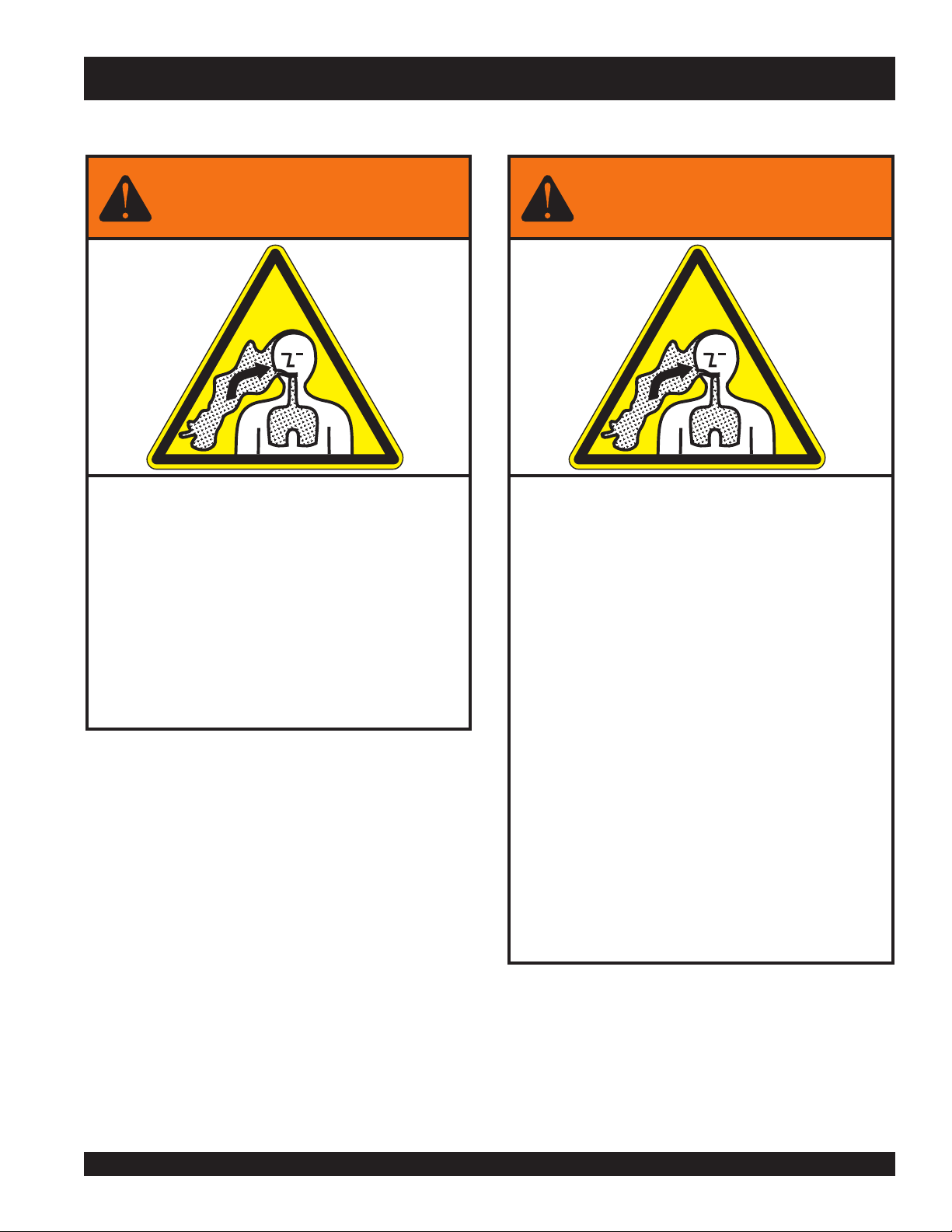
WARNING
SILICOSIS WARNING RESPIRATORY HAZARDS
Grinding/cutting/drilling of masonry, concrete, metal and
other materials with silica in their composition may give
off dust or mists containing crystalline silica. Silica is a
basic component of sand, quartz, brick clay, granite and
numerous other minerals and rocks. Repeated and/or
substantial inhalation of airborne crystalline silica can
cause serious or fatal respiratory diseases, including
silicosis. In addition, California and some other
authorities have listed respirable crystalline silica as a
substance known to cause cancer. When cutting such
materials, always follow the respiratory precautions
mentioned above.
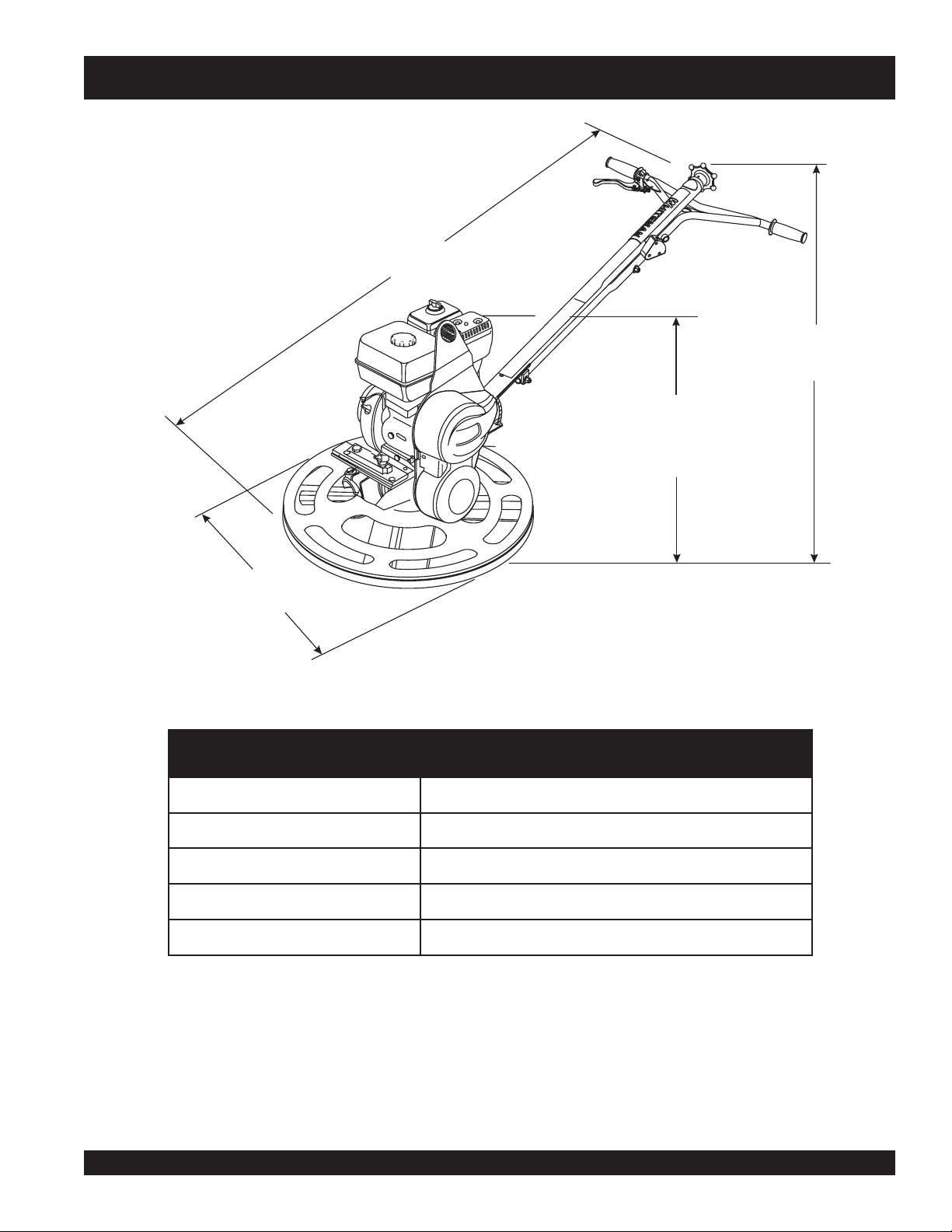
WARNING
Grinding/cutting/drilling of masonry, concrete, metal and
other materials can generate dust, mists and fumes
containing chemicals known to cause serious or fatal
injury or illness, such as respiratory disease, cancer,
birth defects or other reproductive harm. If you are
unfamiliar with the risks associated with the particular
process and/or material being cut or the composition of
the tool being used, review the material safety data
sheet and/or consult your employer, the material
manufacturer/supplier, governmental agencies such as
OSHA and NIOSH and other sources on hazardous
materials. California and some other authorities, for
instance, have published lists of substances known to
cause cancer, reproductive toxicity, or other harmful
effects.
Control dust, mist and fumes at the source where
possible. In this regard use good work practices and
follow the recommendations of the manufacturers or
suppliers, OSHA/NIOSH, and occupational and trade
associations. Water should be used for dust
suppression when wet cutting is feasible. When the
hazards from inhalation of dust, mists and fumes cannot
be eliminated, the operator and any bystanders should
always wear a respirator approved by NIOSH/MSHA for
the materials being used.
Page 4

CA4HC TROWEL— TABLE OF CONTENTS
MQ WHITEMAN CA4HC
WALK-BEHIND TROWEL
Table Of Contents ..................................................... 4
Dimensions ............................................................... 5
Specifications ............................................................ 6
Training Checklist ...................................................... 8
Daily Pre-Operation Checklist ................................... 9
Safety Message Alert Symbols .......................... 10-11
Rules For Safe Operation .................................. 12-13
Operation And Safety Decals .................................. 14
General Information ................................................ 15
Controls and Components ...................................... 16
Basic Engine ........................................................... 17
Handle Assemblies ............................................ 18-19
Pre-Inspection .................................................... 21-22
Initial Start-Up ....................................................23-24
Operation ........................................................... 25-26
Options .................................................................... 26
Maintenance ...................................................... 27-30
Troubleshooting (Trowel) ........................................ 31
Troubleshooting (Engine) ........................................ 32
Terms and Condition Of Sale .................................. 35
NOTE
Specifications and
part numbers are
subject to change
without notice.
PAGE 4 — CA4HC WALK-BEHIND TROWEL— OPERATION MANUAL — REV. #0 (09/29/06)
Page 5
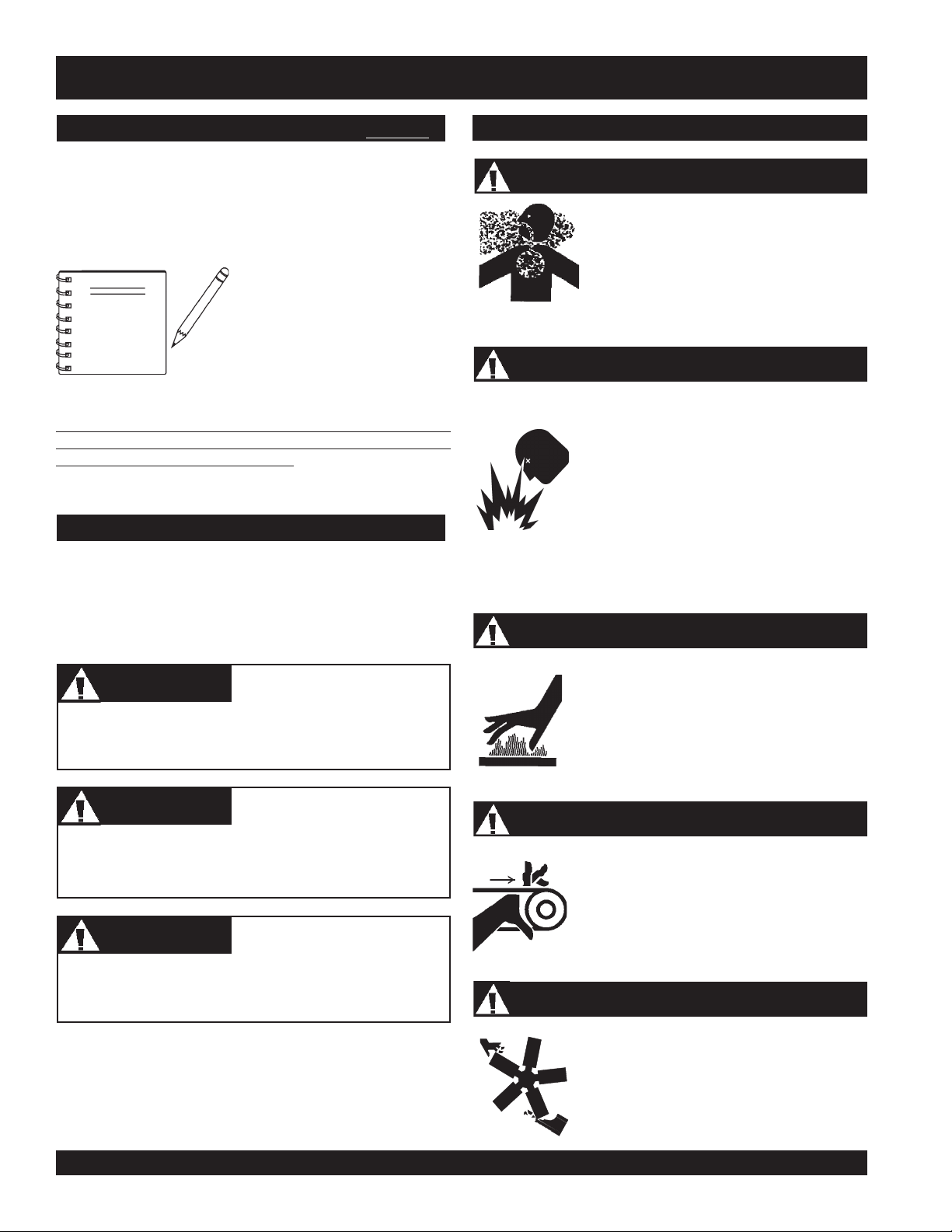
D
CA4HC TROWEL— DIMENSIONS
B
A
C
Figure 1. CA4HC Trowel Dimensions
)elaBgnitfiL(thgieH-A).ni0.82(mm117
)reveLtnemegagnE(thgieH-B).ni52.63(mm129
htdiW-C).ni42(mm016
htgneL-D).tf80.5(m55.1
thgieW).sbl521(gk75
thgieW&snoisnemiDleworTMH4-4AC.1elbaT
CA4HC WALK-BEHIND TROWEL — OPERATION MANUAL — REV. #0 (09/29/06) — PAGE 5
Page 6

CA4HC TROWEL— SPECIFICATIONS
sedalBforebmuN4
retemaiDgniR ).mc16(.ni0.42
rotoR MPR031-07
htdiWhtaP ).mc16(.ni42
snoitacificepSleworTCH4AC.2elbaT
1
)mrA/dnaH(noitarbiV
2
)dethgieW-A(erusserPdnuoS
)dethgieW-C,kaeP(erusserPdnuoS )C(Bd5.09
)dethgieW-A(leveLrewoPdnuoS )A(Bd79
NOTE:
1. The vibration level indicated is the maximum RMS (Root
Mean Square) value obtained at the handle grip while
operating the walk-behind trowel at full throttle on steel
plate with blades partially pitched.
2. Sound pressure is a weighted measure. It is measured at
the operator's ear position while the walk-behind trowel is
operating at full throttle on concrete in a manner most often
experienced in “
may vary depending upon the condition of the concrete.
ledoM 2XQ1K021XGADNOH
epyT rednilyCelgniS,evlavdaehrevO,ekorts-4
ekortSXeroB
normal
snoitacificepSenignE.3elbaT
2
s/m9.81
)A(Bd5.38
” circumstances. Sound pressure
.ni7.1X.ni4.2
)mm24xmm06(
tnemecalpsiD)cc911(.ni.uc3.7
tuptuOxaM .M.P.R006,3ta)SP0.4,Wk9.2(.P.H9.3
enignE
leuFenilosaGdedaelnU
noisnemiD
)HxWxL(
teNyrD
thgieW
PAGE 6 — CA4HC WALK-BEHIND TROWEL— OPERATION MANUAL — REV. #0 (09/29/06)
yticapaCknaTleuF )sretiL5.2(snollaG.S.U66.0.xorppA
deepSeldIdradnatS .M.P.R051-/002+004,1
yticapaCliOebuL )sretiL06.0(strauQ.S.U36.0
dohteMlortnoCdeepS epyTthgiew-ylFlagufirtneC
dohteMgnitratStratSlioceR
.ni5.21X4.31x7.11
)mm813X143X792(
).gK0.31(.sbl7.82
Page 7

NOTE PAGE
CA4HC WALK-BEHIND TROWEL — OPERATION MANUAL — REV. #0 (09/29/06) — PAGE 7
Page 8

CA4HC TROWEL— TRAINING CHECKLIST
TRAINING CHECKLIST
This checklist will lists some of the minimum requirements for
machine maintenance and operation. Please feel free to detach
it and make copies. Use this checklist whenever a new operator
is to be trained or it can be used as a review for more experienced
operator’s.
.ON NOITPIRCSED ?KO ETAD
1 .yletelpmoclaunaMs’rotarepOdaeR
TSILKCEHCGNINIART
2
3 .erudecorpgnileufer,metsysleuF
4 .)gninnurtonenihcam(slortnocfonoitarepO
5 .slortnocytefaS
6 .serudecorppotsycnegremE
7 .enihcamfoputratS
8 .gnirevuenaM
9 .gnihctiP
01 .seuqinhcetgnihsinifetercnoC
11 .enihcamfonwodtuhS
21 .enihcamfognitfiL
dnaenignefognikcehc,stnenopmocfonoitacol,tuoyalenihcaM
.leveldiulfxobraeg
31 .egarotsdnatropsnartenihcaM
Operator _________________________________________ Trainee __________________________________________
COMMENTS:
PAGE 8 — CA4HC WALK-BEHIND TROWEL— OPERATION MANUAL — REV. #0 (09/29/06)
Page 9

CA4HC TROWEL— DAILY PRE-OPERATION CHECKLIST
DAILY PRE-OPERATION CHECKLIST
TSILKCEHCNOITAREPO-ERPYLIAD
1
2
3
4
COMMENTS:
diulFxobraeGleveL
.leveLliOenignE
.
sedalBfonoitidnoC
.
.noitarepOhctiPedalB
CA4HC WALK-BEHIND TROWEL — OPERATION MANUAL — REV. #0 (09/29/06) — PAGE 9
Page 10
CA4HC TROWEL— SAFETY MESSAGE ALERT SYMBOLS
FOR YOUR SAFETY AND THE SAFETY OF OTHERS!
Safety precautions should be followed at all times when operating
this equipment. Failure to read and understand and comply with
the Safety Messages and Operating Instructions could result in
injury to yourself and others.
This Owner's Manual has been developed to provide complete
instructions for the safe and
efficient operation of the MQ
NOTE
Before using this WALK-BEHIND TROWEL, ensure that the
operating individual has read, understands, and complies
with all instructions in this manual.
Whiteman CA4HC TROWEL.
For engine maintenance
information, please refer to the
engine manufacturer's
instructions for data relative to its
safe operation.
HAZARD SYMBOLS
SAFETY MESSAGE ALERT SYMBOLS
The three (3) Safety Messages shown below will inform you
about potential hazards that could injure you or others. The
Safety Messages specifically address the level of exposure to
the operator, and are preceded by one of three words: DANGER,
WARNING, or CAUTION.
Lethal Exhaust Gases
Engine exhaust gases contain poisonous
carbon monoxide. This gas is colorless and
odorless, and can cause death if inhaled.
NEVER operate this equipment in a confined
area or enclosed structure that does not
provide ample free flow air.
Explosive Fuel
Gasoline is extremely flammable, and its
vapors can cause an explosion if ignited. DO
NOT start the engine near spilled fuel or
combustible fluids. DO NOT fill the fuel tank
while the engine is running or hot. DO NOT
overfill tank, since spilled fuel could ignite if it
comes into contact with hot engine parts or
sparks from the ignition system. Store fuel in
approved containers, in well-ventilated areas
and away from sparks and flames. NEVER
use fuel as a cleaning agent.
Burn Hazards
DANGERDANGER
DANGER
DANGERDANGER
You WILL be
if you DO NOT follow these directions.
WARNINGWARNING
WARNING
WARNINGWARNING
You CAN be KILLED or
you DO NOT follow these directions.
CAUTICAUTI
CAUTION
CAUTICAUTI
You CAN be
these directions.
Potential hazards associated with trowel operation will be
referenced with Hazard Symbols which appear throughout this
manual, and will be referenced in conjunction with Safety
Message Alert Symbols.
KILLED
INJURED
if you DO NOT follow
or
SERIOUSLY INJURED
SERIOUSLY INJURED
if
Engine components can generate extreme heat.
To prevent burns, DO NOT touch these areas
while the engine is running or immediately after
operations. NEVER operate the engine with
heat shields or heat guards removed.
Guards and Entanglement Hazards
NEVER operate equipment with covers, or
guards removed. Keep
and
clothing
prevent injury.
away from all moving parts to
fingers, hands, hair
Rotating Blades Hazards
NEVER place hands or feet inside the guard
rings while the engine is running.
PAGE 10 — CA4HC WALK-BEHIND TROWEL— OPERATION MANUAL — REV. #0 (09/29/06)
Page 11
CA4HC TROWEL— SAFETY MESSAGE ALERT SYMBOLS
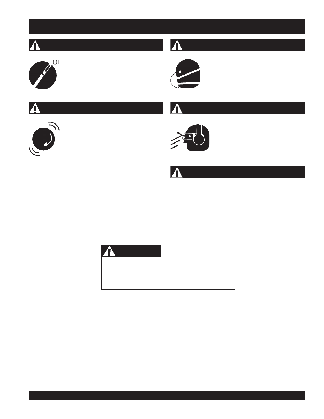
Accidental Starting
ALWAYS place the engine ON/OFF
switch in the OFF position, when the
trowel is not in use.
Over Speed Conditions
NEVER tamper with the factory settings of the
engine governor or settings. Personal injury
and damage to the engine or equipment can
result if operating in speed ranges above
maximum allowable.
Respiratory Hazard
ALWAYS wear approved respiratory protection.
Sight and Hearing hazard
ALWAYS wear approved eye and hearing
protection.
Equipment Damage Messages
Other important messages are provided throughout this manual
to help prevent damage to your trowel, other property, or the
surrounding environment.
CAUTICAUTI
CAUTION
CAUTICAUTI
This walk-behind trowel, other property, or the
surrounding environment could be damaged
if you do not follow instructions.
CA4HC WALK-BEHIND TROWEL — OPERATION MANUAL — REV. #0 (09/29/06) — PAGE 11
Page 12

CA4HC TROWEL — RULES FOR SAFE OPERATION
RULES FOR SAFE OPERATION
WARNINGWARNING
WARNING
WARNINGWARNING
Failure to follow instructions in this manual may lead to serious
injury or even death! This equipment is to be operated by
trained and qualified personnel only! This equipment is for
industrial use only.
■
NEVER operate this equipment when not feeling well due to
fatigue, illness or taking medicine.
■
NEVER operate the trowel under the influence or drugs or
alcohol.
■
Replace nameplate, operation and safety decals when they
become difficult to read.
■
ALWAYS check the trowel for loosened hardware such as
nuts and bolts before starting.
The following safety guidelines should always be used when
operating the CA4HC.
SAFETY
■
DO NOT operate or service this equipment
before reading this entire manual. The
manual must be kept available and accessible
to the operator.
■
This equipment should not be operated by persons under the
minimum statutory age limit.
■
NEVER use this machine for any purpose other than those
described in this manual.
■
NEVER operate the trowel without proper protective clothing,
shatterproof glasses, steel-toed boots and other protective
devices required for the job.
■
NEVER touch the hot exhaust manifold, muffler
or cylinder. Allow these parts to cool before
servicing the trowel.
■
High Temperatures – Allow the engine to cool before adding
fuel or performing service and maintenance functions. Contact
hot!
with
■
The engine of this trowel requires an adequate free flow of
cooling air. NEVER operate the trowel in any enclosed or
■
ALWAYS refuel in a well-ventilated area, away from sparks
and open flames.
components can cause serious burns.
narrow area where free flow
of the air is restricted. If the
air flow is restricted it will
cause serious damage to
the engine and may cause
injury to people. Remember
the engine gives off
DEADLY
gas.
carbon monoxide
■
■
■
NEVER use accessories or attachments which are not
recommended by Multiquip for this equipment. Damage to
the equipment and/or injury to user may result.
■
Manufacturer does not assume responsibility for any accident
due to equipment modifications. Unauthorized equipment
modification will void all warranties. Any modification which
could lead to a change in the original characteristics of the
machine should be made only by the manufacturer who shall
confirm that the machine is in conformity with appropriate
safety regulations.
PAGE 12 — CA4HC WALK-BEHIND TROWEL— OPERATION MANUAL — REV. #0 (09/29/06)
■
■
■
ALWAYS use extreme caution when working with flammable
liquids. When refueling, STOP the engine and allow it to cool.
NEVER operate the trowel in an
explosive atmosphere where fumes
are present, or near combustible
materials. An explosion or fire could
result in severe
death.
NEVER
Fire or explosion could result from
vapors
Topping-off to filler port is dangerous, as it tends to spill fuel.
NEVER use fuel as a cleaning agent.
smoke
, or if fuel is spilled on a
bodily harm or even
around or near the machine.
fuel
hot!
engine.
Page 13

CA4HC TROWEL — RULES FOR SAFE OPERATION
■
NEVER Run engine without air filter. Severe engine damage
may occur. Service air filter frequently to prevent carburetor
malfunction.
■
NEVER place your
while starting or operating this equipment.
■
AVOID wearing jewelry or loose fitting clothing that may snag
on the controls or moving parts as this can cause a serious
injury.
■
ALWAYS keep clear of
operating the trowel.
■
Moving Parts – Shut down the engine before performing
service or maintenance functions. Contact with moving parts
can cause serious injury.
■
ALWAYS check to make sure that the operating area is clear
before starting the engine.
■
NEVER leave the machine
■
ALWAYS be sure the operator is familiar with proper safety
precautions and operations techniques before using trowel.
■
ALWAYS keep the work area well organized.
feet
or
rotating
hands
inside the guard rings
or
moving parts
unattended
while running.
while
■
■
Maintenance Safety
■
■
■
■
■
■
When placing the trowel inside a truck-bed for transport,
always tie-down the trowel.
ALWAYS use proper lifting techniques when moving the
trowel.
NEVER lubricate components or attempt service on a running
trowel.
ALWAYS allow the trowel a proper amount of time to cool
before servicing.
Keep the trowel in proper running condition.
Fix damage to the trowel immediately and always replace
broken parts.
Dispose of hazardous waste properly. Examples of potentially
hazardous waste are used motor oil, fuel and fuel filters.
DO NOT use food or plastic containers to dispose of
hazardous waste.
■
ALWAYS clear the work area of any debris, tools, etc. that
would constitute a hazard while the trowel is in operation.
WARNINGWARNING
WARNING
WARNINGWARNING
ALWAYS check to make sure that the operating area is
clear before starting the engine.
■
No one other than the operator is to be in the working area
when the trowel is in operation.
■
Always observe all applicable compulsory regulations
relevant to environmental protection, especially, fuel storage,
the handling of hazardous substances, and the wearing of
protective clothing and equipment. Instruct the user as
necessary, or, as the user, request this information and
training.
■
ALWAYS store equipment properly when it is not being used.
Equipment should be stored in a clean, dry location out of the
reach of children.
Transporting
Emergencies
■
■
■
ALWAYS know the location of
the nearest
ALWAYS know the location of the
nearest
In emergencies
nearest phone or
Also know the phone numbers of the nearest
ambulance, doctor
information is invaluable in the case of an
emergency and could keep a serious situation from
becoming a tragic one .
fire extinguisher
first aid kit
.
always
keep a phone on the job site
and
.
know the location of the
.
fire department
. This
■
ALWAYS shutdown engine before transporting.
■
Tighten fuel tank cap securely and close fuel cock to prevent
fuel from spilling.
■
Drain fuel when transporting trowel over long distances or
bad roads.
CA4HC WALK-BEHIND TROWEL — OPERATION MANUAL — REV. #0 (09/29/06) — PAGE 13
Page 14

CA4HC TROWEL— OPERATION AND SAFETY DECALS
P/N35168
OPERATION AND SAFETY DECALS
The CA4HC walk-behind trowel is equipped with a number of operation, safety and maintenance decals. Should any of these
decals become unreadable, replacements can be obtained from your dealer.
P
O
W
E
R
R
T
P/N 1848
MODEL
SERIAL NO.
CONTACT
PART S
DEPARTMENT
P/N: 13118
O
W
P/N 2942 WHITE TEXT 13”
L
E
WARNING
To avoid injury,
you MUST read
and understand
operator’s manual
before using this
P/N 11092
machine.
This machine to
be operated by
qualified
personnel only.
Ask for training
as needed.
P/N 35137
P/N 20816
P/N 36099 (ISO Blue)
P/N35137
BELT DRIVE
GEAR DRIVE
CHECK
HOT
CLOCKWISE
GEAR DRIVE
CHECK
COUNTER
CLOCKWISE
LIFTING POINTLIFTING POINT
LUBRICATION
P/N: 1492
(STANDARD MODEL)
P/N: 21455
LUBRICATION
WARNING
P/N: 11246
Engine exhaust and some of
its constituents,and somedust created
by power sanding, sawing, grinding,
drillingand otherconstructionactivities
contains chemicals known to the State
of California to cause cancer, birth
defects and other reproductive harm.
Someexamples of thesechemicals are:
Leadfromlead-based paints.
Crystallinesilica frombricks.
Cementand othermasonryproducts.
ROTATING BLADE
HAZARD
Keep hands
and feet clear
of guard rings.
Stop engine
before servicing.
P/N35168
P/N 35168
PAGE 14 — CA4HC WALK-BEHIND TROWEL— OPERATION MANUAL — REV. #0 (09/29/06)
Arsenicand chromiumfromchemically
treatedlumber.
Yourrisk from these exposures varies,
dependingon howoftenyou dothistype
of work.To reduce your exposure to
these chemicals: work in aALWAYS
well ventilated area, and work with
approved safety equipment, such as
dust masksthat are specially designed
to filterout microscopic particles.
P/N 20525
P/N 21302
Figure 2. Operation and Safety Decals
LUBRICATION
LUBRICATION
P/N 20936
Page 15

CA4HC TROWEL— GENERAL INFORMATION
Intended Use
Operate the CA4HC Trowel, tools and components in accordance
with the manufacturer's instructions. Use of any other tools for
stated operation is considered contrary to designated use. The
risk of such use lies entirely with the user. The manufacturer
cannot be held liable for damages as a result of misuse.
CA4HC Trowel Familiarization
This walk-behind trowel is designed for the
finishing
Take a walk around the trowel. Take notice of all the major
components (see Figure 2) like the engine, blades, Standard or
Quick Pitch™ handle, etc.
Read
be found throughout this manual and on the trowel. Keep all
safety information in good, readable condition. Operators should
be well trained on the operation and maintenance of the trowel.
Before using your trowel, test it on a flat watered down section of
finished concrete that is free of any debris and other objects.
This trial test run will increase your confidence in using the trowel
and at the same time it will familiarize you with the trowel’s
controls. In addition you will understand how the trowel handles
under actual conditions.
of concrete slabs.
all the safety instructions carefully. Safety instructions will
floating
and
Spider
The vertical output shaft of the gearbox connects to a machined
hub called the
that are used for attachment of blades or other accessories.
Remember as the gearbox output shaft rotates so does the spider
assembly.
Guard Ring
This unit is equipped with a special rotating
designed to allow the operator to run the machine alongside
walls, pipes, and obstructions without marring the surface.
Blades
The blades of the trowel finish the concrete as they are rotated
around the surface. This trowel comes equipped with four
combination
spaced in a radial pattern and attached to vertical rotating
shaft by means of the spider assembly
Centrifugal Clutch
In the event of a trowel runaway condition (operator releases
the handle), a
bring the trowel to a halt.
spider
. The spider has 4 arms that extend outward
(8 in./203mm wide)
centrifugal clutch
CAUTIONCAUTION
CAUTION
CAUTIONCAUTION
guard ring
blades
per rotor equally
.
will stop the engine and
. It is
Engine
This trowel is available with an 4 HP
Refer to the engine owner’s manual for instructions regarding
the operation and maintenance of your engine. Please contact
your nearest Multiquip Dealer for a replacement should the
original manual disappear or otherwise become unusable.
Drive System
Power is transferred from the engine to the gearbox input shaft
via a
V-belt pulley drive system
centrifugal clutch. See Parts section of this manual.
Gearbox
gearbox
The
to the spider assembly. The gearbox controls the rotational speed
of the trowel and is equipped with two shafts (input and output).
is located beneath the engine and transfers power
HONDA gasoline engine
. The pulley engages using a
NEVER attempt to
.
the assistance of another person to help lift the trowel .
Training
For proper training, please use the “TRAINING CHECKLIST”
located in the front of this manual (Page 8). This checklist will
provide an outline for an experienced operator to provide training
to a new operator
lift
the trowel by yourself. ALWAYS get
CA4HC WALK-BEHIND TROWEL — OPERATION MANUAL — REV. #0 (09/29/06) — PAGE 15
Page 16

CA4HC TROWEL— CONTROLS AND COMPONENTS
Figure 3. Controls and Components
14
7
10
11
6
8
5
9
1
17
4
3
19
16
13
12
15
18
20
2
Figure 3 shows the location of the basic controls or components,
CA4HC TROWEL
for the
. Listed below is a brief explanation of
each control or component
1. Standard Handle – Employs a "starwheel" for manually
adjusting blade pitch.
2. Foldable Quick Pitch Handle – Employs a lever handle
to quickly adjust blade pitch. Handle folds for storage.
3. Throttle w/ "Kill" Switch – Uses an integrated "kill" switch.
4. Safety Switch – Centrifugal safety switch shuts the engine
off in a "runaway" situation. (Standard Handle)
5. Throttle Control Lever – Controls the speed of the engine.
Move the hand lever towards the operator to increase
engine speed (high), away from the operator to decrease
engine speed (low).
6. Hand Grip/Handle Bar – When operating the trowel, place
both hands on each grip to maneuver the trowel. Replace
hand grips when they become worn or damaged.
7. Engine – Honda GX120 4 H.P. gasoline engine.
8. Pitch Adjust-Standard Handle - Turn clockwise or
counterclockwise to adjust blade pitch.
9. Quick Pitch Handle – Pivots back and forth to adjust blade
pitch.
10. Guard Ring – Helps protect the rotating blades from
damage and helps protect the operator from injury. NEVER
put hands or feet inside the guard ring when engine is
running. NEVER attempt to lift the trowel by the guard ring.
11. Trowel Arm – Provides attachment points for the blades. If
the blades show uneven wear patterns or some blades
wear out faster than others, the trowel arm may need to be
replaced.
12. Blades – This trowel is equipped with special combination
blades. Designed specifically for edging.
13. V-Belt Cover – Remove cover to gain access to the V-belt.
14. Lifting Bale – Provides lifting point for safe lifting of trowel.
15. Thumbwheel Adjuster – Use to adjust throttle cable.
16. Tee Handle – Loosen to fold handle.
17. Trigger Lock – Use to lock blade pitch position.
18. "Kill" Switch – Integrated into Quick Pitch Handle.
19. Throttle Lever Idle Detent – Pressed in, the detent will
hold the lever away from the "kill" switch, allowing the
engine to run at idle.
20. Quick Pitch Latching Bolt – Provides secure positioning
of pitch handle into slotted pitch comb.
PAGE 16 — CA4HC WALK-BEHIND TROWEL— OPERATION MANUAL — REV. #0 (09/29/06)
Page 17

CA4HC TROWEL— BASIC ENGINE
3
Figure 4. Honda GX120 Engine Controls and Components
INITIAL SERVICING
The engine (Figure 4) must be checked for proper lubrication and
filled with fuel prior to operation. Refer to the manufacturer's engine
manual for instructions & details of operation and servicing. The
engine shown above is a HONDA engine, operation for other
types of engines may vary somewhat.
1. Fuel Filler Cap – Remove this cap to add unleaded
gasoline to the fuel tank. Make sure cap is tightened
securely. DO NOT over fill.
DANGER
Adding fuel to the tank should be done only
when the engine is stopped and has had an
opportunity to cool down. In the event of a
fuel spill, DO NOT attempt to start the engine
until the fuel residue has been completely
wiped up, and the area surrounding the
engine is dry.
5. Fuel Valve Lever – OPEN to let fuel flow, CLOSE to stop
the flow of fuel.
6. Choke Lever – Used in the starting of a cold engine, or in
cold weather conditions. The choke enriches the fuel
mixture.
7. Air Cleaner – Prevents dirt and other debris from entering
the fuel system. Remove wing-nut on top of air filter
cannister to gain access to filter element.
NOTE
8. Spark Plug – Provides spark to the ignition system. Set
spark plug gap according to engine manufacturer's
instructions. Clean spark plug once a week.
9. Muffler – Used to reduce noise and emissions.
10. Fuel Tank – Holds unleaded gasoline. For additional
information refer to engine owner's manual.
11
13
12
Operating the engine without an air
filter, with a damaged air filter, or a
filter in need of replacement will
allow dirt to enter the engine, causing
rapid engine wear.
2. Throttle Lever – Used to adjust engine RPM speed (lever
SLOW
advanced forward
FAST
).
3. Engine ON/OFF Switch –
OFF
starting,
4. Recoil Starter (pull rope) – Manual-starting method. Pull
the starter grip until resistance is felt, then pull briskly and
smoothly.
position stops engine operation.
CA4HC WALK-BEHIND TROWEL — OPERATION MANUAL — REV. #0 (09/29/06) — PAGE 17
, lever back toward operator
ON
position permits engine
11. Oil Drain Plug – Remove this plug to remove oil from the
12. Dipstick/Oil Filler Cap – Remove this cap to determine if
13. Output Shaft – Drive power is transferred from the engine
engine's crankcase.
the engine oil is low. Add oil through this filler port as
recommended in Table 4.
output shaft to the gearbox via a V-Belt pulley drive system.
Page 18

CA4HC TROWEL— HANDLE ASSEMBLIES
Assembly and Installation
Before the trowel can be put into operation there are some
components that must be installed before the trowel can be used.
This section provided general instructions on how to install those
components. Instruction sheet p/n 21766 Rev A (Standard
Handle), or Instruction sheet p/n 21849 Rev A (Folding Quick
Pitch Handle) provides further details for the handle assembly.
Handle Tube Installation (All Models)
1. Install the
The mounting hardware should be contained in the shipping
container.
handle tube
4
to the gearbox as shown in (Figure 5).
1
3
Figure 6. Throttle Idle-Run Position (Standard Handle
2
1
3
1 Throttle Cable
2 Throttle Lever
3 Run Position
4 Idle Position
shown)
4
2
1 Main Handle Tube
2 Gearbox
3 Nyloc Hex Nut
4 Hex Screw
Figure 5. Handle Tube Installation
Throttle Cable Connection (All Models)
The throttle cable length is preset
NOTE
and installed into the throttle lever
at the factory.
2. Install the throttle cable to the engine as shown in Figure 7.
6
3
1
8
5
7
2
4
9
1 Adjuster Nut
2 Cable Housing Clamp
3 Swivel Stop Screw
4 Swivel Stop Hole
5 Cable Housing Edge
6 Cable End
7 Housing Clamp Screw
8 Engine Idle Return Spring
9 Cable Ferrule
1. Set the throttle lever to the idle position (Figure 6) (lever away
from the operator).
PAGE 18 — CA4HC WALK-BEHIND TROWEL— OPERATION MANUAL — REV. #0 (09/29/06)
3. Adjust throttle cable at throttle lever on handle bar. (Figure 8)
Figure 7. Throttle Cable to Engine
Page 19

CA4HC TROWEL— HANDLE ASSEMBLIES
1
2
3
4
1
1 Throttle Lever
2 Throttle Cable
3 Idle Detent
4 Thumbwheel Adjuster
Figure 8. Throttle Cable Adjust
Pitch Cable Installation
1. Expose the pitch cable to maximum by adjusting the handle
pitch to the "no pitch", counter-clockwise position (Standard
Handle)(Figure 9). Pivot the pitch handle forward or no
pitch for the folding Quick Pitch handle, (Figure 10).
3
4
2
Figure 10. "No Pitch" Position (Quick Pitch Handle)
2. Remove any nuts from the pitch cable end. Insert the cable
through the yoke eyelet, (Figure 11). Thread the conical
nut up to the eyelet first. Tighten the conical nut by hand to
remove all the slack from the cable.
3. Thread the brass locking nut up to the conical nut. Use a
wrench to tighten the conical nut up against the yoke boss.
This will lock the cable in place. Use a wrench to tighten up
the brass nut up against the yoke boss.
Figure 9. Pitch cable (Standard Handle)
CAUTIONCAUTION
CAUTION
CAUTIONCAUTION
The Quick-Pitch™ handle is spring loaded, personal injury
or damage could result from improper handling or
installation. Be careful when installing this component.
Considerable force may be
NOTE
required when moving the QuickPitch™ handle forward or
backward.
CA4HC WALK-BEHIND TROWEL — OPERATION MANUAL — REV. #0 (09/29/06) — PAGE 19
1 Yoke Eyelet
2 Yoke
3 Conical Nut
4 Locking Nut
Figure 11. Pitch Cable to Yoke Install
Page 20

CA4HC TROWEL— HANDLE ASSEMBLIES
Quick Pitch™ Handle Assembly
If your CA4HC TROWEL is equipped with a folding upper handle
(Figure 12), you will need to unfold and adjust the trowel handle
to the upright position prior to operation. It was assembled at the
factory and shipped in its folded or stowed position.
Considerable force may be
NOTE
Unfolding the Trowel for Operation
1. Make sure that the Quick Pitch™
attached to the upper handle bar and the pitch control cable
has slack. Remove the
on the top side of the upper handle bar, by rotating the
knob counter-clockwise.
required when moving the
Quick Pitch™ handle forward
or backward.
handle
T-handle knob
has been
from the swing bolt
2. Move the Quick Pitch™
position and unfold the upper handle bar away from the
engine into the
so that it fits through the slot in the hinge plate. Turn the Thandle knob counter-clockwise securely to hold upper
handle bar in place.
2. When folding the handle assembly, remember to move the
Quick Pitch™ handle forward first to avoid stretching
the throttle cable.
DO NOT operate unless T-Handle Knob is securely in place.
upright
CAUTIONCAUTION
CAUTION
CAUTIONCAUTION
6
handle
position. Re-insert the swing bolt
toward's the operator's
7
1
4
5
2
3
1 Operational Position
2 Upper Handle
3 T-Handle Knob
4 Quick Pitch Handle forward
when handle in folded position
5 Folded Position
6 Trigger Lock
7 Quick Pitch Handle
Figure 12. Trowel Folded and Operational Positions
PAGE 20 — CA4HC WALK-BEHIND TROWEL— OPERATION MANUAL — REV. #0 (09/29/06)
Page 21

CAUTIONCAUTION
CAUTION
CAUTIONCAUTION
ALWAYS wear approved eye and
hearing protection before operating the
trowel.
NEVER place hands or feet inside the
guard rings while the engine is running.
CA4HC TROWEL— PRE-INSPECTION
Figure 13. Engine Oil Dipstick (Removal)
ALWAYS shut the engine down before
performing any kind of maintenance
service on the trowel.
Before Starting
1. Read safety instructions at the beginning of manual.
2. Clean the trowel, removing dirt and dust, particularly the
engine cooling air inlet, carburetor and air cleaner.
3. Check the air filter for dirt and dust. If air filter is dirty, replace
air filter with a new one as required.
4. Check carburetor for external dirt and dust. Clean with dry
compressed air.
5. Check fastening nuts and bolts for tightness.
Engine Oil Check
1. To check the engine oil level, place the trowel on secure
level ground with the engine stopped.
2. Remove the filler dipstick from the engine oil filler hole
(Figure 13) and wipe clean.
3. Insert and remove the dipstick without screwing it into the filler
neck. Check the oil level shown on the dipstick.
4. If the oil level is low (Figure 14), fill to the edge of the oil filler
hole with the recommended oil type (Table 3). Maximum oil
capacity is 0.48 quarts (.45 liters).
NOTE
Reference manufacturer engine
manual for specific servicing
instructions.
Figure 14. Engine Oil Dipstick (Oil Level)
epyTliO.4elbaT
nosaeS erutarepmeT epyTliO
remmuS rehgiHroC°52 03-W01EAS
llaF/gnirpS C°01~C°52 02/03-W01EAS
retniW rewoLroC°0 01-W01EAS
CA4HC WALK-BEHIND TROWEL — OPERATION MANUAL — REV. #0 (09/29/06) — PAGE 21
Page 22

DANGERDANGER
DANGER
DANGERDANGER
CA4HC TROWEL— PRE-INSPECTION
CAUTIONCAUTION
CAUTION
CAUTIONCAUTION
EXPLOSIVE FUEL!
Motor fuels are highly flammable and can
be dangerous if mishandled. DO NOT
smoke while refueling. DO NOT attempt to
hot!
refuel the trowel if the engine is
running
Fuel Check
1. Remove the gasoline cap located on top of fuel tank.
2. Visually inspect to see if fuel level is low. If fuel is low, replenish
3. When refueling, be sure to use a strainer for filtration. DO
Gearbox Oil
1. Determine if the
.
with unleaded fuel.
NOT top-off fuel. Wipe up any spilled fuel.
gearbox
plug located on the side of the gearbox. This plug will be
marked by the "
level of the lubrication oil should be to the bottom of the fill
plug.
check
oil is low by removing the oil
" decal. See Figure 15. The correct
or
V-Belt Check
A worn or damaged V-belt can adversely affect the performance
of the trowel. If a V-belt is defective or worn simply replace the Vbelt as outlined in the maintenance section of this manual.
Belt Guard Check
Check for damage, loose or missing hardware.
Blade Check
Check for worn or damaged blades. Check to see if one blade is
worn out while the others look new. If this is the case there could
be a blade pitch problem. Refer to the maintenance section of
this manual for blade pitch adjustment procedure. Replace any
worn blades.
Centrifugal Clutch
This finisher model is equipped with a
unit automatically stops rotating when the handle is released.
Disconnect the spark plug wire from the spark plug and
secure away from the engine before performing
maintenance or adjustments on the machine.
centrifugal clutch
. The
1
2
1 Gearbox
2 Oil Level Sight Glass
Figure 15. Gearbox
2. If lubrication oil begins to seep out as the drain plug is
being removed, then it can be assumed that the gearbox
has a sufficient amount of oil.
3. If lubrication oil does not seep out as the drain plug is
being removed, fill with type ISO 680 (P/N 10139) gearbox
lubricant oil until the oil filler hole overflows.
PAGE 22 — CA4HC WALK-BEHIND TROWEL— OPERATION MANUAL — REV. #0 (09/29/06)
Page 23

CA4HC TROWEL — INITIAL START-UP
IDLE
POSITION
THROTTLE
LEVER
This section is intended to assist the operator with the initial
start-up of the walk-behind trowel. It is extremely important that
this section be read carefully before attempting to use the trowel
in the field.
DO NOT use your trowel until this section is thoroughly
understood
Lifting the Trowel Onto a Slab
Extra care should be taken when lifting the trowel off the ground.
Serious damage to the machine or personal injury could be
caused by dropping a trowel.
WARNINGWARNING
WARNING
WARNINGWARNING
NEVER attempt to lift this machine alone. NEVER lift the
trowel by the guard ring as it may rotate and cause injry.
Use only the manufacturer's approved lifting points. The
trowel may be lifted at the center lifting bale by crane or other
lifting device of adequate capacity.
3. Place the
if starting a
Figure 17. Throttle Lever (Idle Position)
choke lever
cold
(Figure 18) in the "
engine.
CLOSED
" position
CAUTIONCAUTION
CAUTION
CAUTIONCAUTION
DO NOT attempt to operate the trowel until the Safety,
General Information and Inspection sections of this manual
have been read and thoroughly understood.
Starting the Engine
1. Place the engine
position.
fuel valve lever
(Figure 16) to the "ON"
4. Place the
starting a
5. Place the
position.
choke lever
Figure 19. Engine Choke Lever (Open)
engine ON/OFF switch
Figure 18. Engine Choke Lever
(Figure 19) in the "
warm engine
or the
temperature is warm.
OPEN
" position if
(Figure 20) in the "
ON
"
Figure 16. Engine Fuel Valve Lever
2. Place the trowel's
position.
CA4HC WALK-BEHIND TROWEL — OPERATION MANUAL — REV. #0 (09/29/06) — PAGE 23
throttle lever
(Figure 17) to the "IDLE"
Figure 20. Engine ON/OFF Switch
Page 24

CA4HC TROWEL — INITIAL START-UP
6. Grasp the starter grip (Figure 21) and slowly pull it out. The
resistance becomes the hardest at a certain position, corresponding to the compression point. Pull the starter grip briskly
and smoothly for starting.
Figure 21. Starter Grip
7. If the engine has started, slowly return the choke lever
OPEN
(Figure 19) to the
repeat steps 1 through 6.
8. Before the trowel is placed into operation, run the engine for
several minutes. Check for fuel leaks, and noises that would
associate with a loose V-belt cover or component.
position. If the engine has not started
Stopping The Engine
1. Move the throttle lever to the IDLE or SLOW position (Figure
22) and run the engine for three minutes at low speed.
2. After the engine
“OFF” position (Figure 23).
Figure 23. Engine ON/OFF Switch (OFF Position)
3. Close the
valve lever to the OFF position.
cools
, turn the engine start/stop switch to the
fuel shut- off valve
(Figure 24) by moving the fuel
To begin troweling, move the throttle lever (Figure 22) toward
9.
FAST
the "
" position.
Figure 22. Throttle Lever (Run Position)
Figure 24. Fuel Valve Lever (OFF Position)
PAGE 24 — CA4HC WALK-BEHIND TROWEL— OPERATION MANUAL — REV. #0 (09/29/06)
Page 25

CA4HC TROWEL — OPERATION
The following steps are intended as a basic guide to machine
operation, and are not to be considered a complete guide to
concrete finishing. We suggest that all operators (experienced
and novice) read “
Concrete Institute, Detroit, Michigan
section of this manual for more information.
The figure illustrates a typical walk-behind trowel application.
Practice maneuvering the trowel. The trick is to let the trowel do
the work.
Slabs on Grade
” published by the
. Read the “Training”
American
Maneuvering the Trowel
1. Get into the operator’s position behind the handle. With a
secure foothold and a firm grasp on the handles slowly
increase the engine speed until the desired blade speed is
obtained.
2. To maneuver the trowel, gently lift up on or press down on
the main trowel handle. To move the machine to the operator’s
left,
down
3. The best method for finishing concrete is to slowly walk
backwards (Figure 25) with the trowel, guiding the trowel
from side to side. This will cover all footprints on wet concrete.
4. Remember that if you let go of the trowel, just step away and
let the trowel come to a complete stop before trying to recover
the trowel.
lift up
on the handle, to move machine to the right,
on the handle.
push
Figure 25. Maneuvering The Trowel
CAUTIONCAUTION
CAUTION
CAUTIONCAUTION
feet
or
hands
NEVER place your
the guard rings while starting or operating
this equipment.
CA4HC WALK-BEHIND TROWEL — OPERATION MANUAL — REV. #0 (09/29/06) — PAGE 25
inside
CAUTIONCAUTION
CAUTION
CAUTIONCAUTION
ALWAYS keep clear of
moving
equipment.
parts while operating this
rotating
or
Page 26

CA4HC TROWEL — OPERATION - OPTIONS
Pitching The Blades - Standard Handle
Adjust the blade pitch on the
26) by turn the Pitch Adjust Wheel clockwise or counterclockwise.
Standard handle
, (Figure
Blades are a vital part of finishing concrete. This finisher has been
designed to finish concrete and is built to stringent quality standards
out of the finest trowel steel. If you need replacement blades,
consult your parts list in this manual for part numbers and order
them from your Multiquip parts dealer or importer.
PITCH ADJUST
WHEEL
Figure 26. Standard Pitch Adjust
Pitching The Blades - Quick Pitch Handle
1. To pitch the blades upwards using the
handle
and pull the handle towards the operator. Pushing the
handle towards the engine will cause the blades to lay
flat.
, (Figure 27) simply squeeze the trigger lock
2
"Quick Pitch
1
Combo Blades
This trowel was equipped with
blades as original equipment. These blades have been designed
for optimum performance in both the floating and finishing of
concrete. These blades are versatile and should take care of most
troweling needs.
™"
combination type
Figure 28. Combination Blade
(Figure 28)
4
1 Quick Pitch Handle
2 Blade Pitch Trigger Lock
3 Increase Blade Pitch
4 Decrease Blade Pitch
(Compresses spring inside handle tube)
Figure 27. Quick Pitch™ Handle
Blades
NOTE
Optional Float Discs (Pans)
These round discs (Figure 29) attach to the spiders and allow the
machine to “
3
Blades should be changed when
they fail to finish concrete in a
satisfactory manner.
floating and easy movement from wet to dry areas. They are also
very effective in embedding large aggregates and surface
hardeners.
float
” on “
wet
” concrete. The disc design allows early
Figure 29. Float Disk (Pan)
PAGE 26 — CA4HC WALK-BEHIND TROWEL— OPERATION MANUAL — REV. #0 (09/29/06)
Page 27

CA4HC TROWEL — MAINTENANCE
See the engine manual supplied
NOTE
with your machine for appropriate
engine maintenance schedule
and troubleshooting guide for
problems.
At the front of the book (Page 10) there is a “
Checklist
basis.
ALWAYS allow the engine to cool before
servicing. NEVER attempt any maintenance
work on a
Disconnect the spark plug wire from the spark plug and
secure away from the engine before performing
maintenance or adjustments on the machine.
MAINTENANCE SCHEDULE
Daily (8-10 Hours)
”. Make copies of this checklist and use it on a daily
CAUTIONCAUTION
CAUTION
CAUTIONCAUTION
hot!
engine.
CAUTIONCAUTION
CAUTION
CAUTIONCAUTION
Daily Pre-Operation
Trowel Arm Adjustment
Use the following procedure to check and adjust trowel arms,
and check for worn or damaged components when it becomes
apparent that the trowel is finishing poorly or in need of routine
maintenance.
Look for the following indications. Trowel arm alignment, worn
spider bushings or bent trowel arms may the cause.
■
■
■
1. Place the trowel in a FLAT, LEVEL area.
A
Any unlevel
will give an incorrect perception of adjustment. Ideally, a 5 x 5 Ft.
(1.5 x 1.5 Meter) three-quarter inch (19 mm) thick
plate should be used for testing.
2. Pitch the blades as flat as possible. The
Are blades wearing unevenly? Is one blade completely
worn out while the others look new?
Does the machine have a perceptible rolling or bouncing
motion when in use?
Look at the machine while it is running; do the guard rings
“rock up and down” relative to the ground?
level
, clean area to test the trowel prior to and after is essential.
spots
in the floor or debris under the trowel blades
FLAT
steel
adjustment bolts
should all barely make contact with the
the spider. If one is not making contact, adjustment will be
necessary. (Item 1, Figure 30).
lower wear plate
on
1. Check the oil level in the engine crankcase and gear box,
fill as necessary.
2. Check V-belt.
Weekly (50-60 Hours)
1. Relube arms, thrust collar and clutch
2. Replace blades if necessary.
3. Check and clean or replace the engine air filter as
necessary.
4. Replace engine oil and filter as necessary, see engine
manual.
Monthly (200-300 Hours)
1. Remove, clean, reinstall and relube the arms and thrust
collar. Adjust the blade arms.
Yearly (2000-2500 Hours)
1. Check and replace if necessary the arm bushings, thrust
collar bushings and shaft seals.
2. Check pitch control cables for wear.
3. Adjust blade speed.
Refer to pages 21 and 22 for oil and lube procedures.
Figure 30 illustrates, "
bushings or bent trowel arms
is barely touching (0.10" max. clearance) lower wear plate. All
alignment bolts should be spaced the same distance from the
lower wear plate.
4
Figure 31 illustrates the "
(as shipped from the factory).
incorrect alignment", worn spider
. Check that the adjustment bolt
1
2
3
1 Adjustment Bolt
2 Lower Wear Plate
3 Surface
4 "Dished" Effect on Finished Concrete
Figure 30. Incorrect Spider Plate Alignment
correct alignment
" for a spider plate
CA4HC WALK-BEHIND TROWEL — OPERATION MANUAL — REV. #0 (09/29/06) — PAGE 27
Page 28

CA4HC TROWEL — MAINTENANCE
1
2
6
1 Gearbox
2 Trowel Arm
3 Surface
3
4 Mounting Bar
5 Blade
6 Correct Alignment
4
5
Figure 31. Correct Spider Plate Alignment
b. Lift the upper trowel assembly off the spider assembly.
Spider Removal
1. Once it is determined that an adjustment is required, remove
the spider assembly from the gearbox shaft as follows:
a. Remove the zerk fitting and allen head screw desig-
nated by the letter "S" (Figure 32). In addition, on the
opposite side of the spider block there is another zerk
fitting and allen head screw, remove both of these
Trowel Arm Removal
1. Remove the two remaining zerk fittings and allen head
screws from the spider assembly (Figure 33).
components.
1 Gearbox
2 Gearbox Shaft
3 Thrust Collar Bearing
4 Thrust Collar
5 Lower Wear Plate
6 Spider Plate
7 Zerk Cap
8 Zerk Fitting
9 Washer
10 Allen Screw
Figure 32. Spider/Gearbox Removal
A slight tap with a rubber mallet may be necessary to
dislodge the spider from the main shaft of the gearbox.
1
2
3
2
2
1
3
4
S
4
1 Spider Plate
2 Zerk Fitting
3 Washer
5
4 Zerk Cap
Figure 33. Trowel Arms Removal
6
8
S
7
PAGE 28 — CA4HC WALK-BEHIND TROWEL— OPERATION MANUAL — REV. #0 (09/29/06)
10
9
Page 29

CA4HC TROWEL — MAINTENANCE
Trowel Blade Removal
CAUTIONCAUTION
CAUTION
CAUTIONCAUTION
Disconnect the spark plug wire from the spark plug and
secure away from the engine before performing
maintenance or adjustments on the machine.
1. Remove the trowel blades from the trowel arm by removing
the two hex head bolts (Figure 34) from the trowel arm. Set
blades aside.
3
5
4
1
2
1 Blade
2 Blade Arm
3 Hex Head Bolt
4 Lock Washer
4 Remove From Arm
Figure 34. Trowel Blades
6. Insert all trowel arms with levers into spider plate (with bronze
bushing already installed) using care to align grease hole on
bronze bushing with grease hole fitting on spider plate.
7. Lock trowel arms in place by tightening the hex head bolt with
zerk grease fitting and jam nut.
8. Re-install the blades onto the trowel arms.
9. Install stabilizer ring onto spider assembly.
10. Lubricate all grease points (zerk fittings) with premium
Lithum 12"
"
consistency.
Changing Blades Only
We recommend that
. The machine may wobble or bounce if only some of the
time
blades are changed at one time.
1. Place the machine on a flat, level surface. Adjust the blade
pitch control to make the blades as flat as possible. Note the
blade orientation on the trowel arm.
NOTE
based grease, conforming to NLG1 Grade #2
all the blades be changed at the
same
Before removing the
blades, please note the
orientation of the blade on
the trowel arm.
Wire brush
2.
trowel arm. Repeat this for the remaining three arms.
Re-Assembly
1. Clean and examine the upper/lower wear plates and thrust
collar. Examine the entire spider assembly. Wire brush any
concrete or rust build-up. If any of the spider components are
found to be damaged or out of round, replace them.
2. Make sure that the bronze trowel arm bushing is not damage
or out of round. Clean the bushing if necessary. If the bronze
bushing is damaged or worn, replace it.
3. Reinstall bronze bushing onto trowel arm.
4. Repeat steps 2 -3 for each trowel arm.
5. Make sure that the spring tensioner is in the correct position
to exert tension on the trowel arm.
any build-up of concrete from all six sides of the
1. Remove the two bolts and lock washers that secure the blade
to the trowel arm. Remove the blade.
2. Using a wire brush, scrape all concrete particles and foreign
debris from the trowel arm.
3. Install the new trowel blade onto the trowel arm. Make sure
blade is installed correctly, maintaining the proper orientation for direction of rotation
4. Reinstall
blade to the trowel arm. Tighten both bolts securely.
5. Repeat steps 1 - 4 for all remaining blades.
CA4HC WALK-BEHIND TROWEL — OPERATION MANUAL — REV. #0 (09/29/06) — PAGE 29
.
the two bolts and lock washers that secure the
Page 30

CA4HC TROWEL — MAINTENANCE
Installing Pans Onto Finisher Blades
WARNINGWARNING
WARNING
WARNINGWARNING
ALWAYS install pans either on the work area or on an area
that is next to and level with the work area. DO NOT lift the
trowel when the pans are attached.
Refer to Figure 35 when installing pans onto finisher blades.
1. Lift trowel just enough to slide pan under blades. Lower
finisher onto pan with blades (item #1) adjacent to Z-Clips
(item #4).
2. Rotate blades into position under Z-Clips. Ensure that the
blades are rotated in the direction of travel when the machine
is in operation or use the engine to rotate the blades into
position.
3. Attach the blade tie-downs (item #3) to the far side of the ZClip brackets (item #4) with tie-down knobs (item #2) as
shown in figure 35.
4. Check to make certain that the blade edges are secured
under the Z-Clips and the tie-downs are secured completely
over the edges of the blade bar before the machine is put back
into operation.
Decommissioning Trowel/Components
Decommissioning is a controlled process used to safely retire a
piece of equipment that is no longer serviceable. If the equipment
poses an
or damage or is no longer cost effective to maintain, (beyond lifecycle reliability) and is to be decommissioned,
dismantlement), the following procedure must take place:
unacceptable and unrepairable safety risk due to wear
(demolition and
1. Drain all fluids completely. These may include oil, gasoline,
2
3
hydraulic oil and antifreeze. Dispose of properly in accordance with local and governmental regulations. Never pour
on ground or dump down drains or
2. The remainder can be brought to a salvage yard or metal
reclamation facility for further dismantling.
sewers.
1
4
1 Blade Assembly
2 Knob, Tie-down Z-Clip Pans
3 Tie-down, Blade
4 Z-Clip, Pan
Figure 35. Pan Installation
PAGE 30 — CA4HC WALK-BEHIND TROWEL— OPERATION MANUAL — REV. #0 (09/29/06)
Page 31

CA4HC TROWEL — TROUBLESHOOTING (TROWEL)
GNITOOHSELBUORT.5ELBAT
MOTPMYS MELBORPELBISSOP NOITULOS
?smraleworttneB
nihctiwSFFO/NOenignE
?snoitcennoceriwesooL .yrassecensariaperroecalpeR.gniriwkcehC
FFO/NOnistcatnocdaB
.yrassecenfihctiws
.yltcerrocgninoitcnuf
.hctiwsFFO/NOecalpeR
.rabedalbehtotlellarapdna
.yletaidemmitiecalper,tnebylthgilsnevesismra
.decalper
ronoitisop"FFO"
?gninoitcnuflam
?leuF
.llatatonrohguorgninnurenignE
,etercnocsllor,secnuob“lewortfI
nislriwsnevenusekamro
.”etercnoc
?noitingI
?hctiws
?sedalB
?tnemtsujdahctiP
?redipS
ecalperroNOsihctiwSFFO/NOenignEehttahterusekaM
otdeilppusgniebleufsierehterusekaM.metsysleufehttakooL
.deggolctonsiretlifleufehttahterusneotkcehC.enigneeht
sidnarewopsahhctiwsnoitingiehttahterusneotkcehC
.nrowylevissecxeton,noitidnocdoognierasedalbniatrecekaM
ehtmorf)mm05("2nahtsselonerusaemdluohssedalbhsiniF
onerusaemdluohssedalbobmoc,egdegniliartehtotrabedalb
thgiartsebdluohsedalbfoegdegniliarT.)mm98("5.3tahtssel
saelgnahctipemasehttateserasedalbllatahtkcehC
rofelbaliavasiloottnemtsujdadleifA.redipsehttaderusaem
).tpeDstraPtcatnoC(.smralewortehtfotnemtsujdathgieh
ehtfoenofI.smraleworttnebrofylbmessaredipsehtkcehC
ehtgnivomybenodebnacsihT.redipsnismrafotifkcehC
fo)mm2.3("8/1nahteromsierehtfI.nwoddnapusmralewort
ebdluohssmradnaredipseht,mraehtfopitehttalevart
?ralloctsurhT
?ralloctsurhT
?nrowgniraebtsurhT
?tfahsniaM
.gninnurelihwnoitom
gnillorelbitpecrepasahenihcaM
?ekoY
?hctiPedalB
.yrassecen
.launam
.ralloctsurhtehtecalper
.tnioptnemhcatta
.yrassecensaekoyecalpeR.pacraeweht
.redipsehtnotignitatorybralloctsurhtehtfossentalfehtkcehC
.ralloctsurhtehtecalper)mm5.0("20.0nahteromybseiravtifI
tlitnactifI.redipsehtnotignikcorybralloctsurhtehtkcehC
,].D.Oralloctsurhtehttaderusaemsa[)mm4.2("23/3nahterom
fiecalpeR.eerfgninnipssititahteesotgniraebtsurhtehtkcehC
ebdluohsylbmessaxobraegehtfotfahstuptuoniamehT
dnathgiartsnurtsumtfahsniamehT.ssenthgiartsrofdekcehc
redipsehttadnuorfotuo)mm80.0("300.0nahteromebtonnac
noylnevesserpekoyehtfosregnifhtobtahterusekamotkcehC
emasehtevahotdetsujdasiedalbhcaetahterusneotkcehC
ninoitcesecnanetniamreptsujdA.sedalbrehtollasahctip
CA4HC WALK-BEHIND TROWEL — OPERATION MANUAL — REV. #0 (09/29/06) — PAGE 31
Page 32

CA4HC TROWEL — TROUBLESHOOTING (ENGINE)
)ENIGNE(GNITOOHSELBUORT.6ELBAT
MOTPMYSESUACELBISSOPNOITULOS
?gnigdirbgulpkrapS
ontub,elbaliavasileuf",tratsottluciffiD
."gulpkrapstaKRAPS
?noitalusni
?evitcefedliocnoitingI.liocnoitingiecalpeR
dna,elbaliavasileuf",tratsottluciffiD
."gulpkrapsehttatneserpsiKRAPS
?gnitiucric
?epytleufgnorW
?gulpkrapsnotisopednobraC .gulpkrapsecalperronaelC
gulpkrapstneicifedoteudtiucrictrohS
?paggulpkrapsreporpmI.pagreporpotteS
?detrohssihctiwsFFO/NO
?ytridstniop,pagkrapsreporpmI
trohsronrownoitalusniresnednoC
?gnitiucrictrohsronekorberiwgulpkrapS
.nrowfiecalper
.hctiws
.stniopnaelc
.gniriw
ronoitalusni,pagkcehC
.gulpkrapsecalper
,noitalusnigulpkrapskcehC
ecalper,gniriwhctiwskcehC
dnapagkrapstcerrocteS
.resnednocecalpeR
gulpkrapsevitcefedecalpeR
ecalperdna,metsysleufhsulF
.leuffoepyttcerrochtiw
?metsysleufnitsudroretaW.metsysleufhsulF
kraps,elbaliavasileuf",tratsottluciffiD
."lamronsinoisserpmocdnatneserpsi
kraps,elbaliavasileuf",tratsottluciffiD
."wolsinoisserpmocdnatneserpsi
.blubgnimirpedisnitneserpleufoN
?ytridrenaelcriA .renaelcriaecalperronaelC
)dlocenignE(?nepOekohC.ekohCesolC
)mrawenignE(?desolCekohC.ekohCnepO
?nrowrednilycro/dnagnirnotsiP
tongulpkrapsro/dnadaehrednilyC
?ylreporpdenethgit
?degamad
?knatleufnielbaliavatonleuF .leuffoepyttcerrochtiwlliF
?deggolcretlifleuF.retlifleufecalpeR
?enilleufniriA.enilleufdeelB
?dedurtorprokcutsevlavtsuahxe/noitcuS.sevlavtaes-eR
teksaggulpkrapsro/dnateksagdaeH
?deggolcelohrehtaerbpacknatleuF .packnatleufecalperronaelC
rodnasgnirnotsipecalpeR
.notsip
dnastlobdaehrednilyceuqroT
.gulpkraps
gulpkrapsdnadaehecalpeR
.steksag
PAGE 32 — CA4HC WALK-BEHIND TROWEL— OPERATION MANUAL — REV. #0 (09/29/06)
Page 33

NOTE PAGE
CA4HC WALK-BEHIND TROWEL — OPERATION MANUAL — REV. #0 (09/29/06) — PAGE 33
Page 34

NOTE PAGE
PAGE 34 — CA4HC WALK-BEHIND TROWEL— OPERATION MANUAL — REV. #0 (09/29/06)
Page 35

Effective: February 22, 2006
TERMS AND CONDITIONS OF SALE — PARTS
PAYMENT TERMS
Terms of payment for parts are net 30 days.
FREIGHT POLICY
All parts orders will be shipped collect or
prepaid with the charges added to the invoice.
All shipments are F.O.B. point of origin.
Multiquip’s responsibility ceases when a signed
manifest has been obtained from the carrier,
and any claim for shortage or damage must be
settled between the consignee and the carrier.
MINIMUM ORDER
The minimum charge for orders from Multiquip is $15.00 net. Customers will be asked
for instructions regarding handling of orders
not meeting this requirement.
RETURNED GOODS POLICY
Return shipments will be accepted and credit
will be allowed, subject to the following provisions:
1. A Returned Material Authorization must
be approved by Multiquip prior to shipment.
2. To obtain a Return Mater ial Authorization,
a list must be provided to Multiquip Parts
Sales that defines item numbers, quantities, and descriptions of the items to be
returned.
a. The parts numbers and descriptions
must match the current parts price
list.
b. The list must be typed or computer
generated.
c. The list must state the reason(s) for
the return.
d. The list must reference the sales
order(s) or invoice(s) under which the
items were originally purchased.
e. The list must include the name and
phone number of the person requesting the RMA.
3. A copy of the Return Material Authorization must accompany the return shipment.
4. Freight is at the sender’s expense. All
parts must be returned freight prepaid to
Multiquip’s designated receiving point.
5. Parts must be in new and resalable con-
6. The following items are not returnable:
7. The sender will be notified of any material
8. Such material will be held for five working
9. Credit on returned parts will be issued at
10. In cases where an item is accepted, for
11. Credit issued will be applied to future
PRICING AND REBATES
Prices are subject to change without prior
notice. Price changes are effective on a specific date and all orders received on or after that
date will be billed at the revised price. Rebates
for price declines and added charges for price
increases will not be made for stock on hand
at the time of any price change.
Multiquip reserves the right to quote and sell
dition, in the original Multiquip package (if
any), and with Multiquip part numbers
clearly marked.
a. Obsolete parts. (If an item is in the
price book and shows as being replaced by another item, it is obsolete.)
b. Any parts with a limited shelf life
(such as gaskets, seals, “O” rings,
and other rubber parts) that were purchased more than six months prior to
the return date.
c. Any line item with an extended dealer
net price of less than $5.00.
d. Special order items.
e. Electrical components.
f. Paint, chemicals, and lubricants.
g. Decals and paper products.
h. Items purchased in kits.
received that is not acceptable.
days from notification, pending instructions. If a reply is not received within five
days, the material will be returned to the
sender at his expense.
dealer net price at time of the original
purchase, less a 15% restocking charge.
which the original purchase document
can not be determined, the price will be
based on the list price that was effective
twelve months prior to the RMA date.
purchases only.
direct to Government agencies, and to Original
Equipment Manufacturer accounts who use
our products as integral parts of their own
products.
SPECIAL EXPEDITING SERVICE
A $35.00 surcharge will be added to the invoice
for special handling including bus shipments,
insured parcel post or in cases where Multiquip
must personally deliver the parts to the carrier.
LIMITATIONS OF SELLER’S LIABILITY
Multiquip shall not be liable hereunder for
damages in excess of the purchase price of the
item with respect to which damages are
claimed, and in no event shall Multiquip be
liable for loss of profit or good will or for any
other special, consequential or incidental dam-
ages.
LIMITATION OF WARRANTIES
No warranties, express or implied, are made
in connection with the sale of parts or trade
accessories nor as to any engine not manufac-
tured by Multiquip. Such warranties made in
connection with the sale of new, complete units
are made exclusively by a statement of war-
ranty packaged with such units, and Multiquip
neither assumes nor authorizes any person to
assume for it any other obligation or liability
whatever in connection with the sale of its
products. Apart from such written statement of
warranty, there are no warranties, express,
implied or statutory, which extend beyond the
description of the products on the face hereof.
CA4HC WALK-BEHIND TROWEL — OPERATION MANUAL — REV. #0 (09/29/06) — PAGE 35
Page 36

OPERATION MANUAL
HERE'S HOW TO GET HELP
PLEASE HAVE THE MODEL AND SERIAL
NUMBER
ON-HAND
WHEN CALLING
UNITED STATES
Multiquip Corporate Office MQ Parts Department
18910 Wilmington Ave. Tel. (800) 421-1244 800-427-1244 Fax: 800-672-7877
Carson, CA 90746 Fax (800) 537-3927 310-537-3700 Fax: 310-637-3284
Contact: mq@multiquip.com
Mayco Parts Warranty Department
800-306-2926 Fax: 800-672-7877 800-421-1244, Ext. 279 Fax: 310-537-1173
310-537-3700 Fax: 310-637-3284 310-537-3700, Ext. 279
Service Department Technial Assistance
800-421-1244 Fax: 310-537-4259 800-478-1244 Fax: 310-631-5032
310-537-3700
MEXICO UNITED KINGDOM
MQ Cipsa Multiquip (UK) Limited Head Office
Carr. Fed. Mexico-Puebla KM 126.5 Tel. (52) 222-225-9900 Hanover Mill, Fitzroy Street, Tel. 0161 339 2223
Momoxpan, Cholula, Puebla 72760 Mexico Fax (52) 222-285-0420 Ashton-under-Lyne, Fax 0161 339 3226
Contact: pmastretta@cipsa.com.mx Lancashire OL7 0TL
Contact: sales@multiquip.co.uk
CANADA BRAZIL
Multiquip Multiquip
4110 Industriel Boul. Tel. (450) 625-2244 Av. Evandro Lins e Silva, 840 - grupo 505 Tel. 011-55-21-3433-9055
Laval, Quebec, Canada H7L 6V3 Fax (450) 625-8664 Barra de Tijuca - Rio de Janeiro Fax 011-55-21-3433-9055
Contact: jmartin@multiquip.com Contact: cnavarro@multiquip.com.br, srentes@multiquip.com.br
© COPYRIGHT 2006, MULTIQUIP INC.
Multiquip Inc, the MQ logo and the Whiteman logo are registered trademarks of Multiquip Inc. and may not be used, reproduced, or altered without written permission. All
other trademarks are the property of their respective owners and used with permission.
This manual MUST accompany the equipment at all times. This manual is considered a permanent part of the equipment and should remain with the unit if resold.
The information and specifications included in this publication were in effect at the time of approval for printing. Illustrations are based on the
Walk-Behind Power Trowel.
Multiquip Inc. reserves the right to discontinue or change specifications, design or the information published in this publication at any time without notice and without
incurring any obligations.
Illustrations, descriptions, references and technical data contained in this manual are for guidance only and may not be considered as binding.
Your Local Dealer is:
MULTIQUIP INC
18910 WILMINGTON AVE.
CARSON, CALIFORNIA 90746
800-421-1244 • 310-537-3700
FAX: 310-537-3927
E-mail:mq@multiquip.com
Internet:multiquip.com
MQ Whiteman CA4HC Series
..
.
..
 Loading...