

Page 1

OPERATION AND PARTS MANUAL
C-4 FINISHER
WALK-BEHIND TROWEL
MODEL #
SERIAL #
© COPYRIGHT 2002, MULTIQUIP INC.
Revision #1 (07/24/02)
MULTIQUIP INC
18910 WILMINGTON AVE. 800-427-1244
CARSON, CALIFORNIA 90746 FAX: 800-672-7877
310-537-3700
800-421-1244 800-478-1244
FAX: 310-537-3927 FAX: 310-631-5032
E-mail:mq@multiquip.com • www:multiquip.com
Atlanta • Boise • Dallas • Houston • Newark
Montreal, Canada • Manchester, UK
Rio De Janiero, Brazil • Guadalajara, Mexico
..
. PARTS DEPARTMENT:
..
SERVICE DEPARTMENT/TECHNICAL ASSISTANCE:
P/N 10689
Page 2

Page 3

HERE'S HOW TO GET HELP
PLEASE HAVE THE MODEL AND SERIAL NUMBER
ON-HAND WHEN CALLING
PARTS DEPARTMENT
800-427-1244 or 310-537-3700
FAX: 800-672-7877 or 310-637-3284
SERVICE DEPARTMENT/TECHNICAL ASSISTANCE
800-478-1244 or 310-537-3700
FAX: 310- 537-4259
WARRANTY DEPARTMENT
888-661-4279, or 310-661-4279
FAX: 310- 537-1173
MAIN
800-421-1244 or 310-537-3700
FAX: 310-537-3927
C-4 FINISHER WALK-BEHIND TROWEL — PARTS & OPERATION MANUAL — REV. #1 (07/24/02) — PAGE 3
Page 4

C-4 FINISHER TROWEL— TABLE OF CONTENTS
Here's How To Get Help ............................................ 3
Table Of Contents ..................................................... 4
Parts Ordering Procedures ....................................... 5
Training Checklist ...................................................... 6
Daily Pre-Operation Checklist ................................... 7
Safety Message Alert Symbols .............................. 8-9
Rules For Safe Operation .................................. 10-11
Operation And Safety Decals .................................. 12
Specifications (Trowel) ............................................ 12
Specifications (Engine) ........................................... 14
General Information ................................................ 15
MQ WHITEMAN — C-4 FINISHER TROWEL
Controls and Components ...................................... 16
Basic Engine ........................................................... 17
Assembly ................................................................. 18
Pre-Inspection .................................................... 19-20
Initial Start-Up (Gasoline Engine) ......................21-22
Operation ........................................................... 23-24
Options .................................................................... 25
Maintenance ...................................................... 26-29
Troubleshooting (Trowel) ................................... 30-31
Troubleshooting (Engine) ........................................ 32
Explanation of Codes in Remarks Column ............. 34
Suggested Spare Parts ........................................... 35
Nameplate and Decals.......................................36-37
Quick Pitch™ Handle Assembly........................ 38-39
Spider and Blades Assembly ............................. 40-41
Gearbox Assembly ............................................. 42-43
Engine2.5 HP Honda Assembly ......................... 44-45
Guard Ring Assy. ............................................... 46-47
Blades and Adjustment Fixture Assembly ......... 48-49
HONDA GX240K1 ENGINE
Air Cleaner Assembly......................................... 50-51
Camshaft Assembly ........................................... 52-53
Carburetor Assembly ......................................... 54-55
Control Assembly ............................................... 56-57
Crankcase Cover Assembly ............................... 58-59
Crankshaft Assembly .........................................60-61
Cylinder Barrel Assembly ................................... 62-63
Fan Cover Assembly .......................................... 64-65
Flywheel Assembly ............................................ 66-67
Fuel Tank Assembly ........................................... 68-69
Gasket Kit Assembly ............................................... 71
Ignition Coil Assembly ........................................ 72-73
Muffler Assembly ............................................... 74-75
Piston Assembly ................................................. 76-77
Recoil Starter Assembly.....................................78-79
Labels Assembly ................................................ 80-81
Terms and Conditions of Sale — Parts ................... 82
NOTE
Specification and part
number are subject to
change without notice.
PAGE 4 — C-4 FINISHER WALK-BEHIND TROWEL— PARTS & OPERATION MANUAL — REV. #0 (07/24/02)
Page 5
C-4 FINISHER TROWEL— PARTS ORDERING PROCEDURES
■■
■ Dealer account number
■■
■■
■ Dealer name and address
■■
■■
■ Shipping address (if different than billing address)
■■
■■
■ Return fax number
■■
■■
■ Applicable model number
■■
■■
■ Quantity, part number and description of each part
■■
■■
■ Specify preferred method of shipment:
■■
UPS Ground
•
UPS Second Day or Third Day*
•
UPS Next Day*
•
Federal Express Priority One (please provide us with your Federal
•
Express account number)*
Airborne Express*
•
Truck or parcel post
•
*Normally shipped the same day the order is received, if prior to 2PM west coast time.
Earn Extra Discounts when
you order by FAX!
All parts orders which include complete part numbers
and are received by fax qualify for the following extra
discounts:
Number of
line items ordered Additional Discount
1-9 items 3%
10+ items** 5%
Get special freight allowances
when you order 10 or more
line items via FAX!**
■■
■
UPS Ground Service at no charge for freight
■■
■■
■
UPS Third Day Service at one-half of actual freight
■■
cost
Extra Fax DiscountExtra Fax Discount
Extra Fax Discount
Extra Fax DiscountExtra Fax Discount
for Domestic USAfor Domestic USA
for Domestic USA
for Domestic USAfor Domestic USA
Dealers OnlyDealers Only
Dealers Only
Dealers OnlyDealers Only
Now! Direct TOLL-FREE access
to our Parts Department!
Toll-free nationwide:
No other allowances on freight shipped by any other carrier.
**Common nuts, bolts and washers (all items under $1.00 list price)
do not count towards the 10+ line items.
800-421-1244
Toll-free FAX:
800/6-PARTS-7 • 800-672-7877
*DISCOUNTS ARE SUBJECT TO CHANGE*
Fax order discount and UPS special programs revised June 1, 1995
C-4 FINISHER WALK-BEHIND TROWEL — PARTS & OPERATION MANUAL — REV. #1 (07/24/02) — PAGE 5
Page 6

C-4 FINISHER TROWEL— TRAINING CHECKLIST
TRAINING CHECKLIST
This checklist will lists some of the minimum requirements for
machine maintenance and operation. Please feel free to detach
it and make copies. Use this checklist whenever a new operator
is to be trained or it can be used as a review for more experienced
operator’s.
.ON NOITPIRCSED ?KO ETAD
1 .yletelpmoclaunaMs’rotarepOdaeR
TSILKCEHCGNINIART
2
3 erudecorpgnileufer,metsysleuF
4 .)gninnurtonenihcam(slortnocfonoitarepO
5 .noitarepohctulc,slortnocytefaS
6 .serudecorppotsycnegremE
7 .enihcamfoputratS
8 gnirevuenaM
9 gnihctiP
01 .seuqinhcetgnihsinifetercnoC
11 .enihcamfonwodtuhS
21 .)tnempiuqelanoitpo(enihcamfognitfiL
31 .egarotsdnatropsnartenihcaM
dnaenignefognikcehc,stnenopmocfonoitacol,tuoyalenihcaM
.leveldiulfxobraeg
Operator _________________________________________ Trainee __________________________________________
COMMENTS:
PAGE 6 — C-4 FINISHER WALK-BEHIND TROWEL— PARTS & OPERATION MANUAL — REV. #0 (07/24/02)
Page 7

C-4 FINISHER TROWEL— DAILY PRE-OPERATION CHECKLIST
DAILY PRE-OPERATION CHECKLIST
1 .leveLliOenignE
2 .leveLdiulFxobraeG
3 .sedalBfonoitidnoC
4 .noitarepOhctiPedalB
5 noitarepOhctulC
COMMENTS:
TSILKCEHCNOITAREPO-ERPYLIAD
C-4 FINISHER WALK-BEHIND TROWEL — PARTS & OPERATION MANUAL — REV. #1 (07/24/02) — PAGE 7
Page 8
C-4 FINISHER TROWEL— SAFETY MESSAGE ALERT SYMBOLS
FOR YOUR SAFETY AND THE SAFETY OF OTHERS!
Safety precautions should be followed at all times when operating
this equipment. Failure to read and understand the Safety
Messages and Operating Instructions could result in injury to
yourself and others.
HAZARD SYMBOLS
NOTE
This Owner's Manual has been developed to provide
complete instructions for the safe and efficient operation
of the MQ Whiteman C-4 FINISHER TROWEL. For
engine maintenance information, please refer to the
engine manufacturers instructions for data relative to its
safe operation.
Before using this WALK-BEHIND TROWEL, ensure
that the operating individual has read and
understands all instructions in this manual.
SAFETY MESSAGE ALERT SYMBOLS
The three (3) Safety Messages shown below will inform you
about potential hazards that could injure you or others. The
Safety Messages specifically address the level of exposure to
the operator, and are preceded by one of three words: DANGER,
WARNING, or CAUTION.
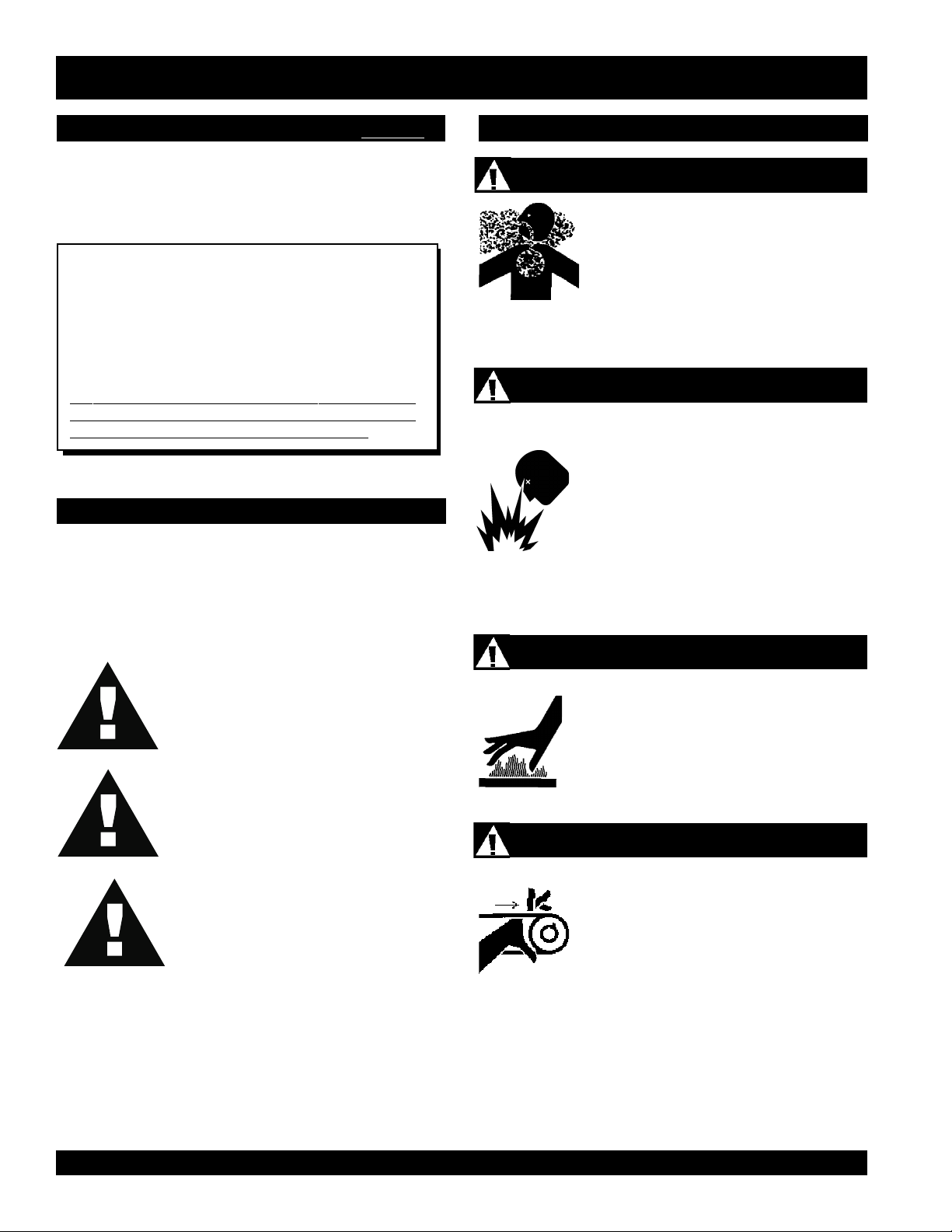
Lethal Exhaust Gases
Engine exhaust gases contain poisonous
carbon monoxide. This gas is colorless and
odorless, and can cause death if inhaled.
NEVER operate this equipment in a confined
area or enclosed structure that does not
provide ample free flow air.
Explosive Fuel
Gasoline is extremely flammable, and its
vapors can cause an explosion if ignited. DO
NOT start the engine near spilled fuel or
combustible fluids. DO NOT fill the fuel tank
while the engine is running or hot. DO NOT
overfill tank, since spilled fuel could ignite if it
comes into contact with hot engine parts or
sparks from the ignition system. Store fuel in
approved containers, in well-ventilated areas
and away from sparks and flames. NEVER
use fuel as a cleaning agent.
DANGER: You WILL be KILLED or
SERIOUSLY injured if you DO NOT follow
directions.
WARNING: You CAN be KILLED or
SERIOUSLY injured if you DO NOT follow
directions.
CAUTION: You CAN be injured if you
DO NOT follow directions.
Potential hazards associated with C-4 FINISHER trowel
operation will be referenced with "
appear throughout this manual, and will be referenced in
conjunction with Safety "
Message Alert Symbols
Hazard Symbols
" which
".
Burn Hazards
Engine components can generate extreme heat.
To prevent burns, DO NOT touch these areas
while the engine is running or immediately after
operations. NEVER operate the engine with
heat shields or heat guards removed.
Rotating Parts
NEVER operate equipment with covers, or
guards removed. Keep fingers,
clothing
injury.
away from all moving parts to prevent
hands, hair
and
PAGE 8 — C-4 FINISHER WALK-BEHIND TROWEL— PARTS & OPERATION MANUAL — REV. #0 (07/24/02)
Page 9
C-4 FINISHER TROWEL— SAFETY MESSAGE ALERT SYMBOLS
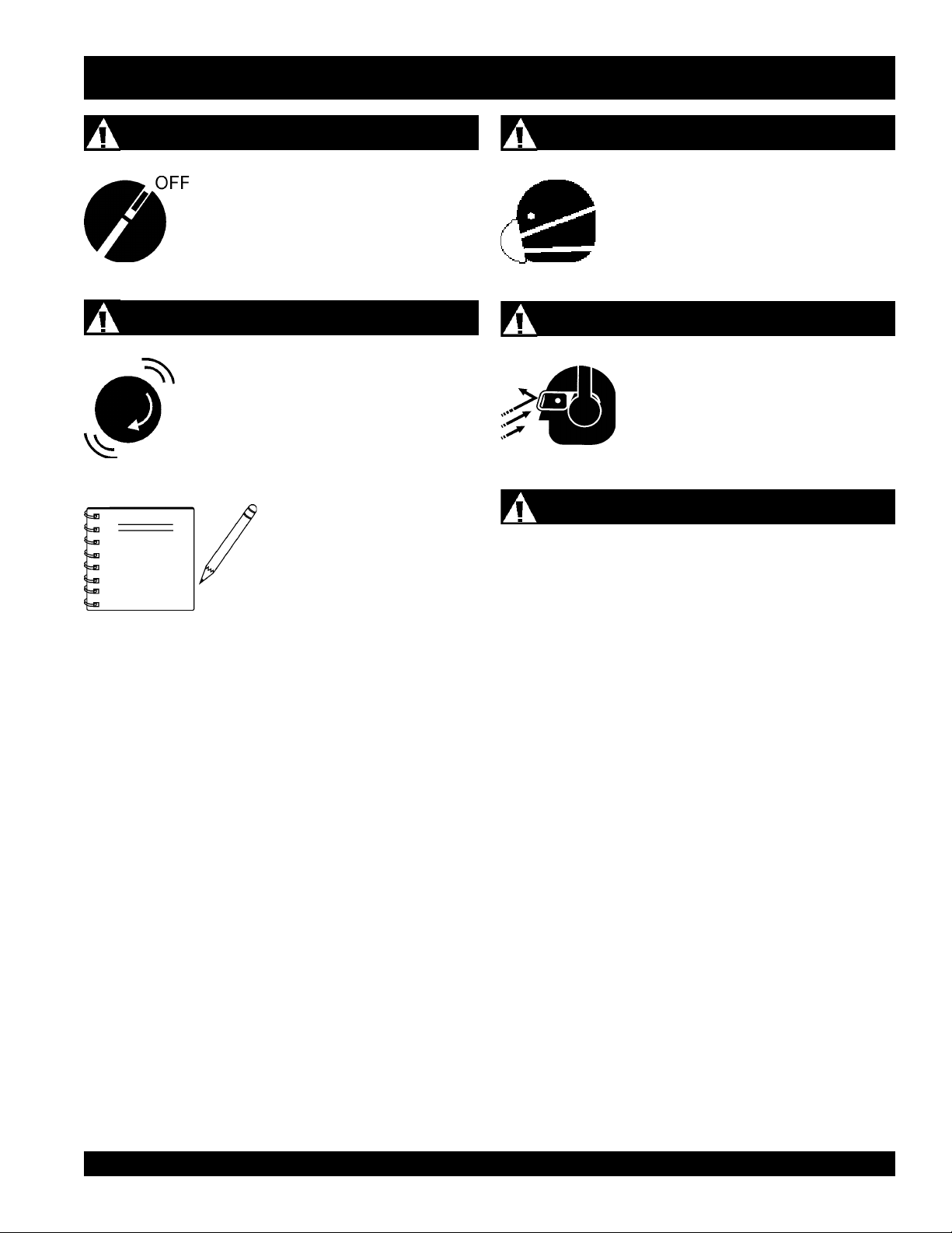
Accidental Starting
ALWAYS place the engine ON/OFF
switch in the OFF position, when the
trowel is not in use.
Over Speed Conditions
NEVER tamper with the factory settings of the
engine governor or settings. Personal injury
and damage to the engine or equipment can
result if operating in speed ranges above
maximum allowable.
This
property, or the surrounding
NOTE
environment could be damaged
if you do not follow instructions.
walk-behind trowel
, other
Respiratory Hazard
ALWAYS wear approved respiratory
protection.
Sight and Hearing hazard
ALWAYS wear approved eye and hearing
protection.
Equipment Damage Messages
Other important messages are provided throughout this manual
to help prevent damage to your trowel, other property, or the
surrounding environment.
C-4 FINISHER WALK-BEHIND TROWEL — PARTS & OPERATION MANUAL — REV. #1 (07/24/02) — PAGE 9
Page 10
C-4 FINISHER TROWEL — RULES FOR SAFE OPERATION
■
CAUTION:
Failure to follow instructions in this manual may
lead to serious injury or even death! This
equipment is to be operated by trained and
qualified personnel only! This equipment is
for industrial use only.
The following safety guidelines should always be used when
operating the
SAFETY
■
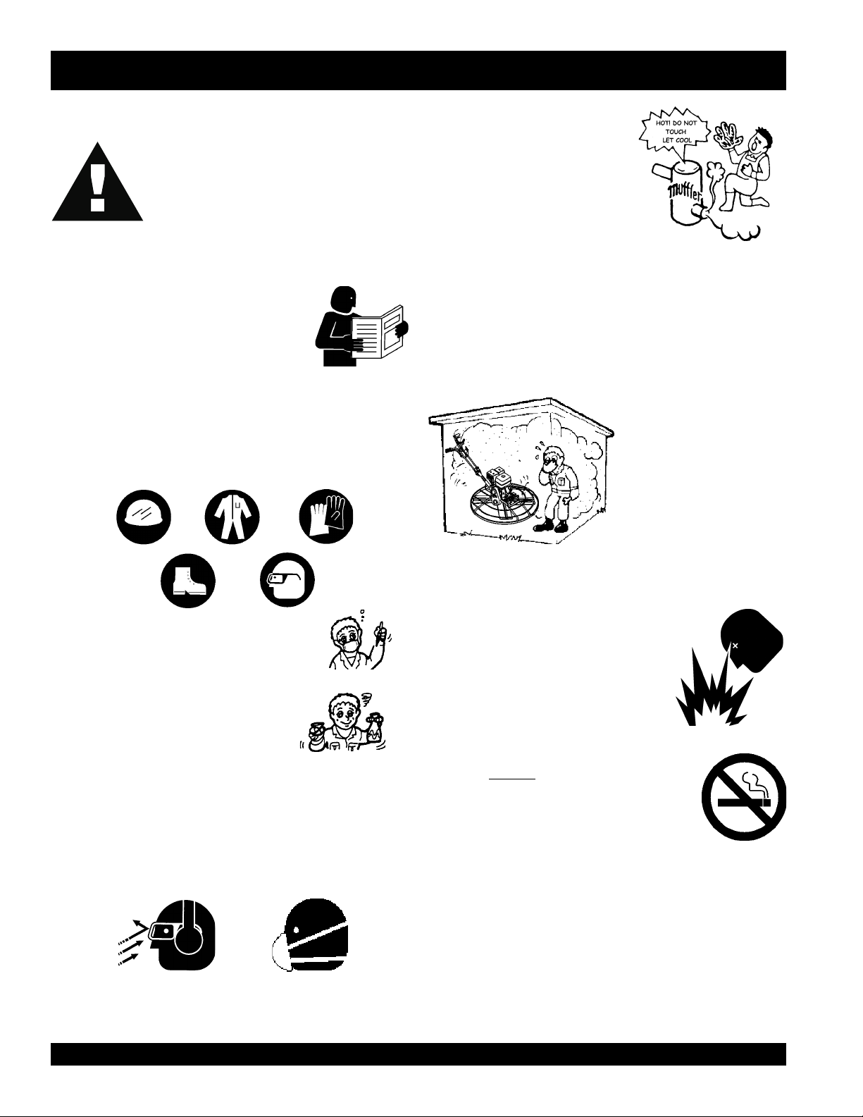
DO NOT operate or service this equipment
before reading this entire manual.
■
This equipment should not be operated by
persons under 18 years of age.
■
NEVER operate the trowel without proper protective clothing,
shatterproof glasses, steel-toed boots and other protective
devices required by the job.
C-4 FINISHER
walk-behind power trowel.
NEVER touch the hot exhaust
manifold, muffler or cylinder. Allow
these parts to cool before servicing
the trowel.
■
High Temperatures – Allow the engine to cool before adding
fuel or performing service and maintenance functions. Contact
hot!
with
■
The engine of this trowel requires an adequate free flow of
cooling air. NEVER operate the trowel in any enclosed or
components can cause serious burns.
narrow area where free flow
of the air is restricted. If the
air flow is restricted it will
cause serious damage to
the trowel's engine and
may cause injury to people.
Remember the trowel's
engine gives off
carbon monoxide gas.
DEADLY
■
■
NEVER operate this equipment when not
feeling well due to fatigue, illness or taking
medicine.
■
NEVER operate the trowel under the
influence or drugs or alcohol.
■
ALWAYS check the trowel for loosened threads or bolts before
starting.
■
ALWAYS wear proper
protection equipment when operating the trowel.
■
Manufacture does not assume responsibility for any accident
due to equipment modifications.
respiratory
(mask),
hearing
and
eye
■
■
■
■
■
■
ALWAYS refuel in a well-ventilated area, away from sparks
and open flames.
ALWAYS use extreme caution when
working with flammable liquids. When
refueling, stop the engine and allow it
to cool.
NEVER
Fire or explosion could result from
vapors
NEVER operate the trowel in an explosive atmosphere or
near combustible materials. An explosion or fire could result
causing severe
Topping-off to filler port is dangerous, as it tends to spill fuel.
NEVER use accessories or attachments, which are not
recommended by Multiquip for this equipment. Damage to
the equipment and/or injury to user may result.
Whenever necessary, replace nameplate, operation and
safety decals when they become difficult read.
smoke
, or if fuel is spilled on a
around or near the machine.
hot!
bodily harm or even death.
fuel
engine.
PAGE 10 — C-4 FINISHER WALK-BEHIND TROWEL— PARTS & OPERATION MANUAL — REV. #0 (07/24/02)
Page 11
C-4 FINISHER TROWEL — RULES FOR SAFE OPERATION
■
NEVER Run engine without air filter. Severe engine may
occur. Service air filter frequently to prevent carburetor
malfunction.
■
NEVER place your
feet
or
hands
inside the guard rings
while starting or operating this equipment.
■
AVOID wearing jewelry or loose fitting clothing that may snag
on the controls or moving parts, this can cause a serious
injury.
■
ALWAYS keep clear of
rotating
or
moving parts
while
operating the trowel.
■
Moving Parts – Shut down the engine before performing
service or maintenance functions. Contact with moving parts
can cause serious injury.
■
ALWAYS check to make sure that the operating area is clear
before starting the engine.
■
NEVER leave the machine
■
ALWAYS be sure the operator is familiar with proper safety
precautions and operations techniques before using trowel.
unattended
while running.
Maintenance Safety
■
■
■
■
■
■
Emergencies
■
NEVER lubricate components or attempt service on a running
trowel.
ALWAYS allow the trowel a proper amount of time to cool
before servicing.
Keep the trowel in proper running condition.
Fix damage to the trowel immediately and always replace
broken parts.
Dispose of hazardous waste properly. Examples of potentially
hazardous waste are used motor oil, fuel and fuel filters.
DO NOT use food or plastic containers to dispose of
hazardous waste.
ALWAYS know the location of the nearest
fire extinguisher
.
■
ALWAYS store equipment properly when it is not being used.
Equipment should be stored in a clean, dry location out of the
reach of children.
■
ALWAYS read, understand, and follow procedures in
Operator’s Manual before attempting to operate equipment.
■
ALWAYS store equipment properly when it is not being used.
Equipment should be stored in a clean, dry location out of the
reach of children.
■
Refer to the
technical questions or information
HONDA Engine Owner's Manual
for engine
recommended by Multiquip
for this equipment. Damage to the equipment and/or injury to
■
■
user may result.
Transporting
■
ALWAYS shutdown engine before transporting.
■
Tighten fuel tank cap securely and close fuel cock to prevent
fuel from spilling.
■
Drain fuel when transporting trowel over long distances or
bad roads.
■
When placing the trowel inside a truck-bed for transport,
always tie-down the trowel.
ALWAYS know the location of the nearest and
In emergencys
nearest phone or
always
know the location of the
keep a phone on the job site
first aid kit
.
.
Also know the phone numbers of the nearest
ambulance, doctor
and
fire department
. This
information will be invaluable in the case of an
emergency.
■
ALWAYS use proper lifting techniques when moving the
trowel.
C-4 FINISHER WALK-BEHIND TROWEL — PARTS & OPERATION MANUAL — REV. #1 (07/24/02) — PAGE 11
Page 12
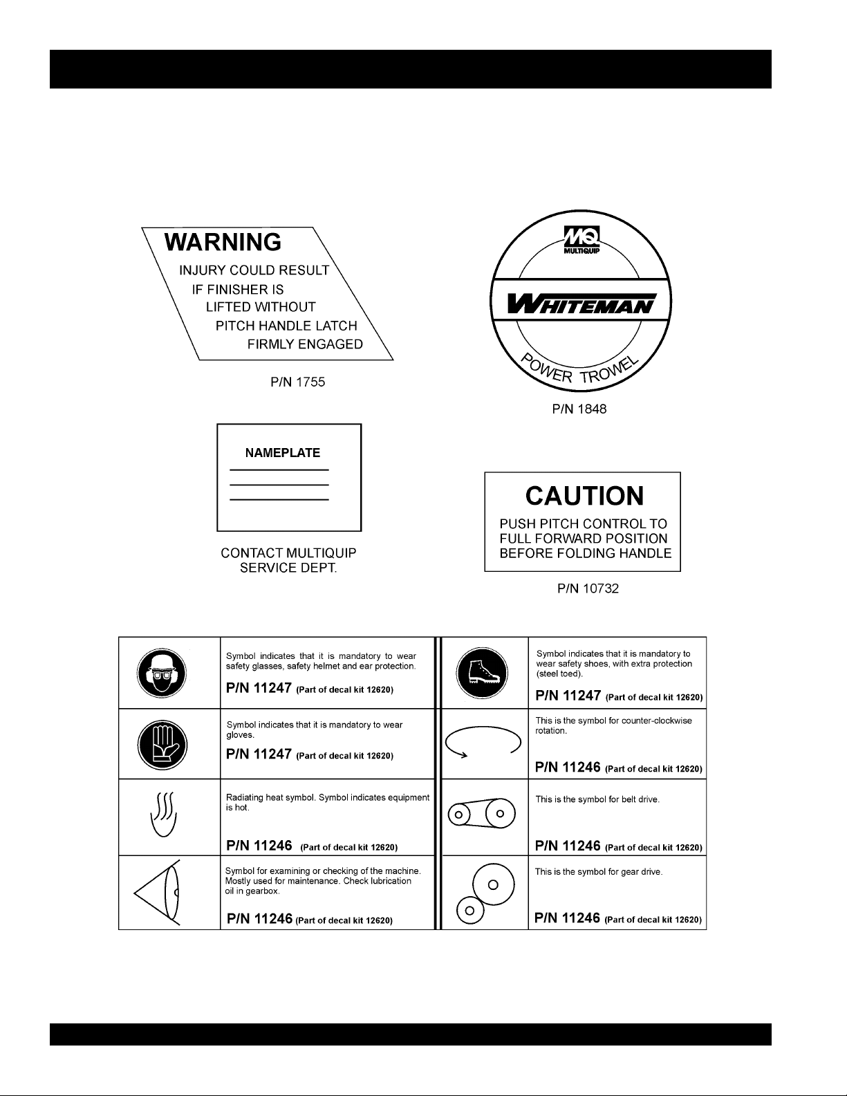
C-4 FINISHER TROWEL— OPERATION AND SAFETY DECALS
Machine Safety Decals
The
C-4 Finisher
safety and maintenance information. Figure 1 below illustrates these decals as they appear on the machine. Should any of these
decals become unreadable, replacements can be obtained from your dealer.
walk-behind trowel is equipped with a number of safety decals (Figure 1). These decals are provided for operator
Figure 1. C-4 Finisher Decals
PAGE 12 — C-4 FINISHER WALK-BEHIND TROWEL— PARTS & OPERATION MANUAL — REV. #0 (07/24/02)
Page 13
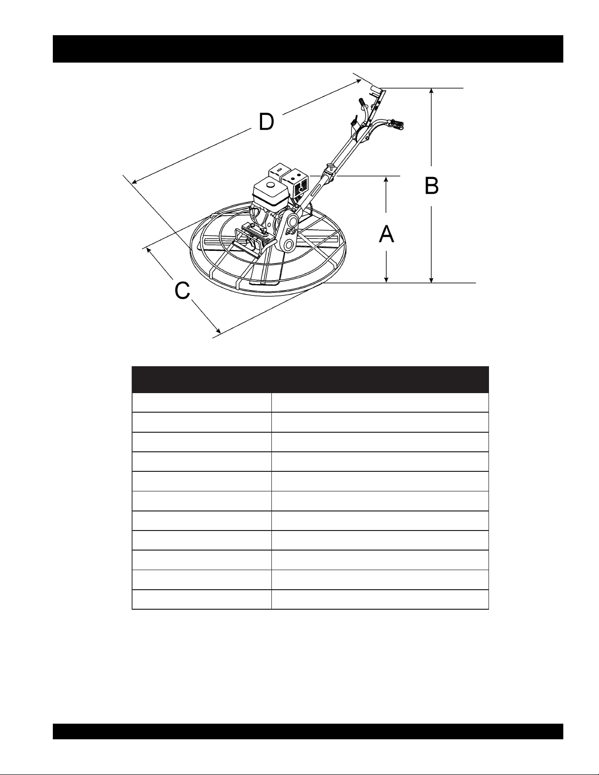
C-4 FINISHER TROWEL— SPECIFICATIONS (TROWEL)
Figure 2. C-4 Finisher Trowel Dimensions
)elaBgnitfiL(thgieH-A).mm795(.ni5.32
)reveLtnemegagnE(thgieH-B).mm129(.ni52.63
htdiW-C).mm016(.ni42
htgneL-D).mm055,1(.ni16
erusserPdnuoSbd49
noitarbiVs/m(g0.2
retemaiDgniR).mc(.ni
sedalBforebmuN4
rotoRMPR701-05
htdiWhtaP).mc16(.ni42
thgieW).gk14(.sbl09
NOTE:
1. Sound pressure is a weighted measure. Measured at the
operators ear position while the walk-behind trowel is
operating at full throttle on concrete in a manner most often
experienced in “
normal
” circumstances. Sound pressure
may vary depending upon the condition of the concrete.
Hearing protection is always recommended.
2. The vibration level indicated is the maximum RMS (Root
Mean Square) value obtained at the handle grip while
operating the walk-behind trowel on curing concrete in a
manner most often experienced in “
Values were obtained from all three axes of motion. The
values shown represent the maximum RMS value from
these measurements.
snoitacificepSleworTseireS4-C.1elbaT
2
)
normal
” circumstances.
C-4 FINISHER WALK-BEHIND TROWEL — PARTS & OPERATION MANUAL — REV. #1 (07/24/02) — PAGE 13
Page 14

C-4 FINISHER TROWEL— SPECIFICATIONS (ENGINE)
snoitacificepSenignE.2elbaT
ledoM 2AQ2K001GADNOH
epyT rednilyCelgniS,evlavediS,ekorts-4
ekortSXeroB
tnemecalpsiD)cc89(.ni.uc0.6
tuptuOxaM .M.P.R006,3ta.P.H5.2
rotoMcirtcelE/enignE
leuF enilosaGelibomotuAdedaelnU
)HxWxL(noisnemiD
thgieWteNyrD ).gK7.8(sbl2.91
yticapaCknaTleuF )sretiL4.1(snollaG.S.U73.0.xorppA
deepSeldIdradnatS.M.P.R001±004,1
yticapaCliOebuL )sretiL54.0(strauQ.S.U84.0
dohteMlortnoCdeepS epyTthgiew-ylFlagufirtneC
dohteMgnitratStratSlioceR
.ni1.81X.ni5.02
)mm64xmm25(
.ni6.31X6.01x8.01
)mm543X072X572(
PAGE 14 — C-4 FINISHER WALK-BEHIND TROWEL— PARTS & OPERATION MANUAL — REV. #0 (07/24/02)
Page 15

C-4 FINISHER TROWEL— GENERAL INFORMATION
C-4 Trowel Finisher Familiarization
This walk-behind finisher is designed for the
finishing
Take a walk around the trowel. Take notice of all the major
components (see Figure 3, page16) like the engine, blades,
Quick Pitch™ handle, clutch lever, etc. Check that there is always
oil in the engine.
Read
be found throughout this manual and on the trowel. Keep all
safety information in good, readable condition. Operators should
be well trained on the operation and maintenance of the trowel.
Before using your trowel, test it on a flat watered down section of
finished concrete that is free of any debris and other objects.
This trial test run will increase your confidence in using the trowel
and at the same time it will familiarize you with the trowel’s
controls. In addition you will understand how the trowel handles
under actual conditions.
Engines
This trowel is available with an 2.5 HP
Refer to the engine owner’s manual for instructions regarding
the operation and maintenance of your engine. The engine
manual is included with your trowel at the time of shipping from
Whiteman. Please contact your nearest Multiquip Dealer for a
replacement should the original manual disappear.
Drive System
Power is transferred from the engine to the gearbox input shaft
via a V-belt pulley drive system. The pulley engages using a
manual clutch. See parts section of this manual.
of concrete slabs.
all the safety instructions carefully. Safety instructions will
HONDA
floating
gasoline engine.
and
Blades
The blades of the trowel finish the concrete as they are rotated
around the surface. Blades are classified as
inches wide),
wide). This trowel comes equipped with four blades per
rotor equally spaced in a radial pattern and attached to
vertical rotating shaft by means of a
Manual Clutch
In the event of a trowel runaway condition (operator releases
the handle), a
the trowel to a halt.
CAUTIONCAUTION
CAUTION
CAUTIONCAUTION
Moving the Trowel
This trowel is light weight, however for safety purposes always
two people
use
Training
For proper training, please use the “TRAINING CHECKLIST”
located in the front of this manual (Page 6). This checklist will
provide an outline for an experienced operator to provide training
to a new operator
combination
float
(10 or 8 inches wide), and finish (6 inches
spider assembly.
manual clutch
NEVER attempt to
ALWAYS get the assistance of another
person to help lift the trowel .
to lift the trowel up onto a slab of concrete.
will stop the engine and bring
lift
the trowel by yourself.
(8
Gearbox
gearbox
The
spider
to the
of the trowel and is equipped with two shafts (input and output).
Spider
The vertical output shaft of the gearbox connects to a cast hub
called the
that are used for attachment of blades or other accessories.
Remember as the gearbox output shaft rotates so does the spider
assembly.
is located beneath the engine and transfers power
assembly. The gearbox controls the rotational speed
spider
. The spider has 4 arms that extend outward
C-4 FINISHER WALK-BEHIND TROWEL — PARTS & OPERATION MANUAL — REV. #1 (07/24/02) — PAGE 15
Page 16
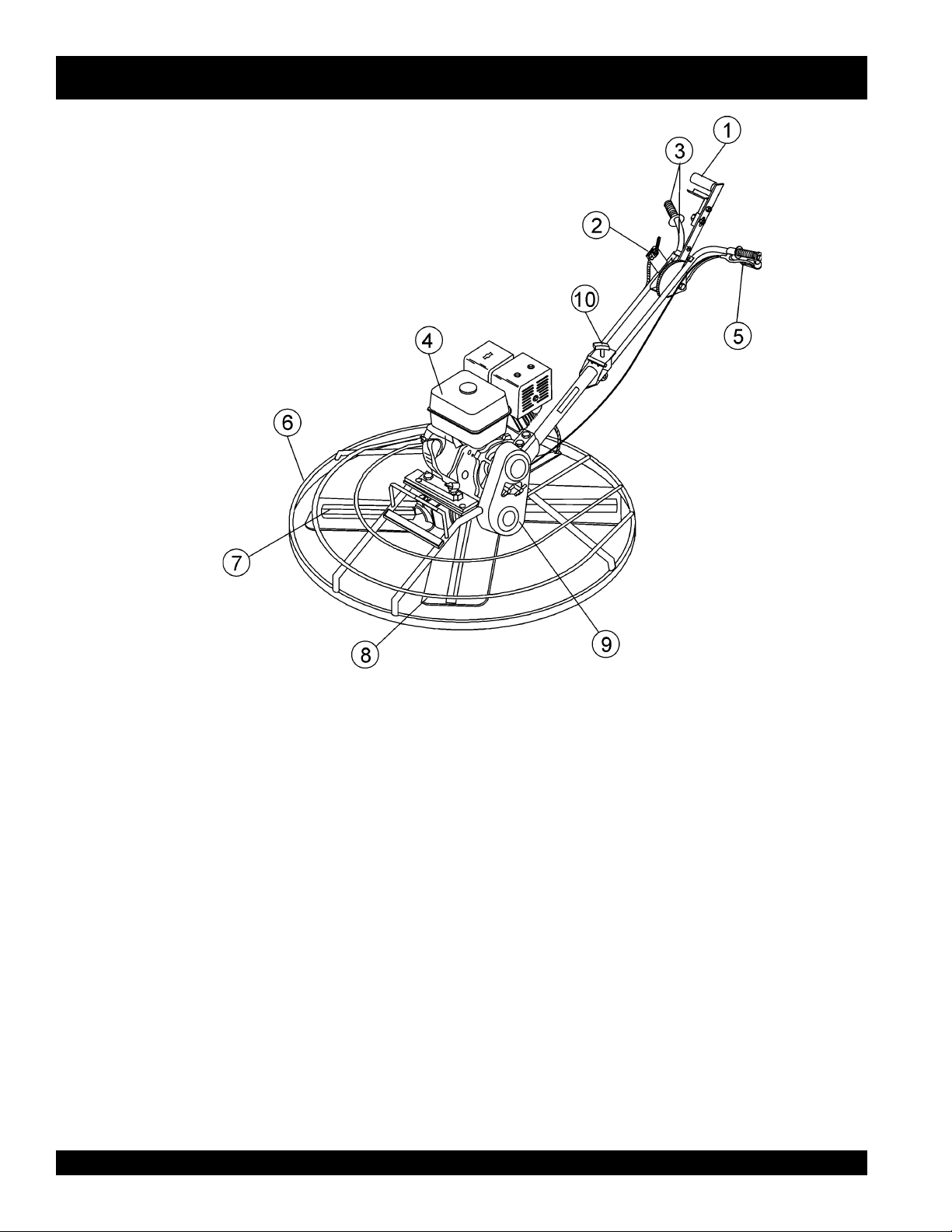
C-4 FINISHER TROWEL— CONTROLS AND COMPONENTS
Figure 3. Controls and Components
Figures 3 shows the location of the basic controls or components,
C-4 FINISHER
for the
of each control or component
1. Quick Pitch™ Control Handle – To adjust the pitch of
the blades, grasp the handle then squeeze and either move
the handle forward or backward to achieve the desired
blade pitch.
2. Throttle Control Lever – Controls the speed of the engine.
Move the hand lever towards the operator to increase
engine speed (high), away from the operator to decrease
engine speed (low).
3. Hand Grip/Handle Bar – When operating the trowel, place
both hands on each grip to maneuver the trowel. Replace
hand grips when they become worn or damaged.
4. Engine – This trowel uses a Honda G100K2QA2 gasoline
engine.
5. Clutch Lever - Clutch engagement lever. When this lever
is engaged, the blades will begin to rotate.
trowel. Listed below is a brief explanation
6. Guard Ring- NEVER! put hands or feet inside guard ring.
7. Trowel Arm – NEVER operate the trowel with a bent, broken
or out of adjustment trowel arm. If the blades show uneven
wear patterns or some blades wear out faster than others,
the trowel arm may need to be replaced.
8. Blades – This trowel is equipped with combination blades.
These blades are versatile and should take care of most
troweling needs. In addition float discs can be attached to
the trowel arms that will allow the trowel to float on "
concrete.
9. V-Belt Cover – Remove this cover to gain access to the Vbelt. NEVER operate the trowel with this cover removed.
10. T-Handle Release Knob – Turn this handle counterclockwise to release the upper handle and place in either
down position or operate position. Turn handle clockwise
to lock upper handle in place.
wet
"
PAGE 16 — C-4 FINISHER WALK-BEHIND TROWEL— PARTS & OPERATION MANUAL — REV. #0 (07/24/02)
Page 17
C-4 FINISHER TROWEL— BASIC ENGINE
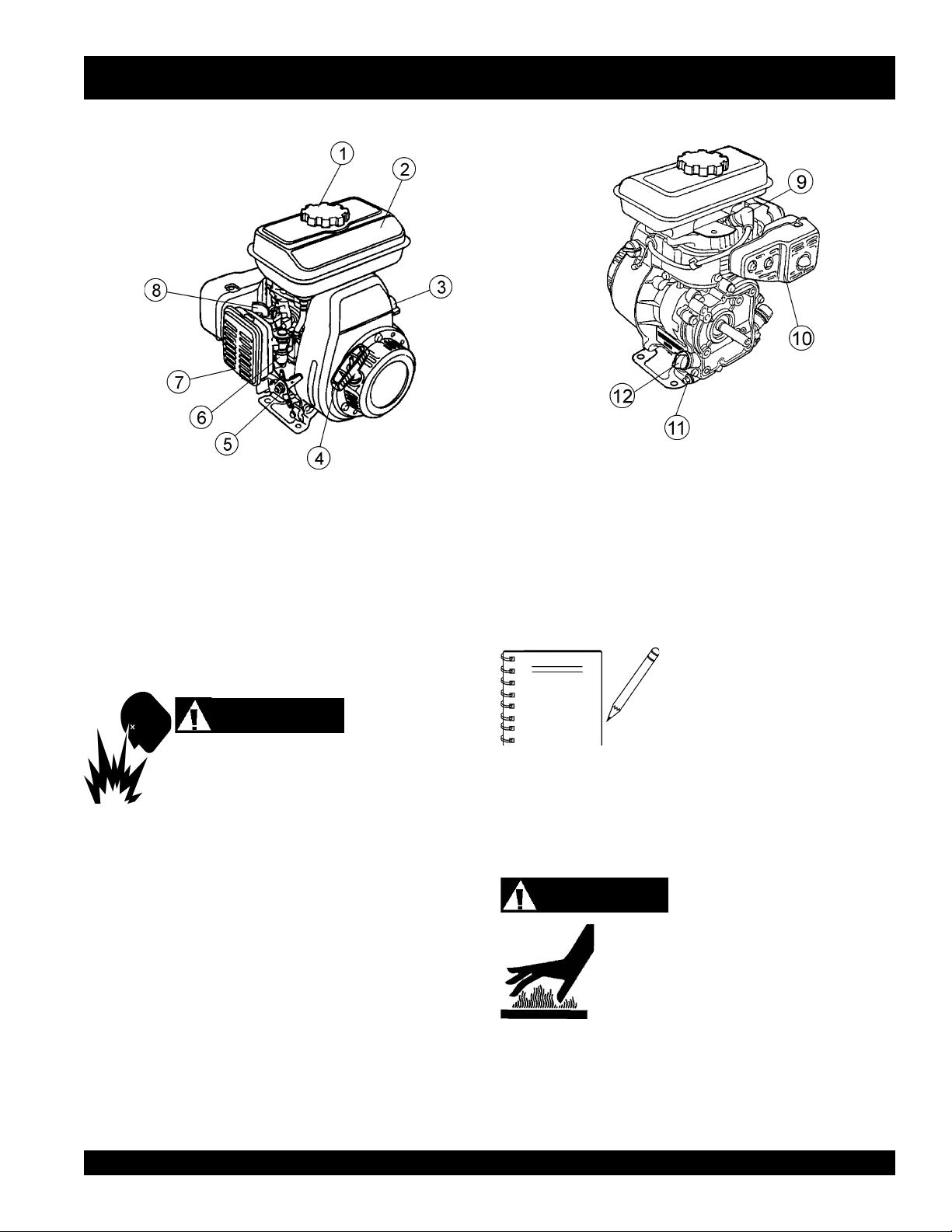
Figure 4. Engine Controls and Components
INITIAL SERVICING
The engine (Figure 4) must be checked for proper lubrication and
filled with fuel prior to operation. Refer to the manufacturers engine
manual for instructions & details of operation and servicing. The
engine shown above is a HONDA engine, operation for other
types of engines may vary somewhat.
1. Fuel Filler Cap – Remove this cap to add unleaded
gasoline to the fuel tank. Make sure cap is tightened
securely. DO NOT over fill.
DANGER
Adding fuel to the tank should be done only when
the engine is stopped and has had an opportunity to
cool down. In the event of a fuel spill, DO NOT
attempt to start the engine until the fuel residue has been completely
wiped up, and the area surrounding the engine is dry.
2. Fuel Tank – Holds unleaded gasoline. For additional
information refer to engine owner's manual.
3. Engine ON/OFF Switch –
OFF
starting,
4. Recoil Starter (pull rope) – Manual-starting method. Pull
the starter grip until resistance is felt, then pull briskly and
smoothly.
5. Throttle Lever – Used to adjust engine RPM speed (lever
advanced forward
FAST
).
Fuel Valve Lever – OPEN to let fuel flow, CLOSE to stop
6.
the flow of fuel.
position stops engine operation.
SLOW
ON
position permits engine
, lever back toward operator
7. Air Cleaner – Prevents dirt and other debris from entering
the fuel system. Remove wing-nut on top of air filter
cannister to gain access to filter element.
8. Choke Lever – Used in the starting of a cold engine, or in
cold weather conditions. The choke enriches the fuel
mixture.
NOTE
9. Spark Plug – Provides spark to the ignition system. Set
spark plug gap to 0.6 - 0.7 mm (0.028 - 0.031 inch) Clean
spark plug once a week.
10. Muffler – Used to reduce noise and emissions.
11. Oil Drain Plug – Remove this plug to remove oil from the
engine's crankcase.
12. Dipstick/Oil Filler Cap – Remove this cap to determine if
the engine oil is low. Add oil through this filler port as
recommended in Table 3.
Operating the engine without an air
filter, with a damaged air filter, or a
filter in need of replacement will
allow dirt to enter the engine,
causing rapid engine wear.
WARNING
Engine components can generate extreme heat.
To prevent burns, DO NOT touch these areas
while the engine is running or immediately after
operating. NEVER operate the engine with the
muffler removed.
C-4 FINISHER WALK-BEHIND TROWEL — PARTS & OPERATION MANUAL — REV. #1 (07/24/02) — PAGE 17
Page 18
C-4 FINISHER TROWEL — ASSEMBLY
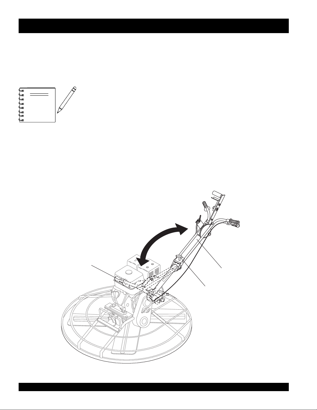
Quick Pitch™ Handle Assembly
The C-4 finisher trowel is equipped with a folding upper handle
(Figure 4). It was assembled at the factory and shipped in its
folded or stow position. You will need to unfold and adjust the
trowel handle to the upright position prior to operation.
Considerable force may be
NOTE
Unfolding the Trowel for Operation
required when moving the
Quick Pitch™ handle forward
or backward.
1. Make sure that the Quick Pitch™
attached to the upper handle bar and the pitch control cable
has slack. Remove the
on the top side of the upper handle bar, by rotating the
knob counter-clockwise. Move the Quick Pitch™
toward's the operator's position and unfold the upper
handle bar away from the engine into the
Re-insert the swing bolt so that it fits through the slot in the
hinge plate. Turn the T-handle knob counter-clockwise
securely to hold upper handle bar in place.
T-handle knob
FOLDED
POSITION
handle
has been
from the swing bolt
handle
upright
position.
OPERATIONAL
POSITION
UPPER
HANDLE
T-HANDLE
KNOB
Figure 5. Trowel Folded and Operational
Positions
PAGE 18 — C-4 FINISHER WALK-BEHIND TROWEL— PARTS & OPERATION MANUAL — REV. #0 (07/24/02)
Page 19
C-4 FINISHER TROWEL— PRE-INSPECTION
CAUTIONCAUTION
CAUTION
CAUTIONCAUTION
NEVER operate the trowel
in a confined area or
enclosed area structure
that does not provide ample
free flow of air
ALWAYS wear approved eye and hearing
protection before operating the trowel.
NEVER place hands or feet inside the guard
rings while the engine is running. ALWAYS shut
the engine down before performing any kind
of maintenance service on the trowel.
.
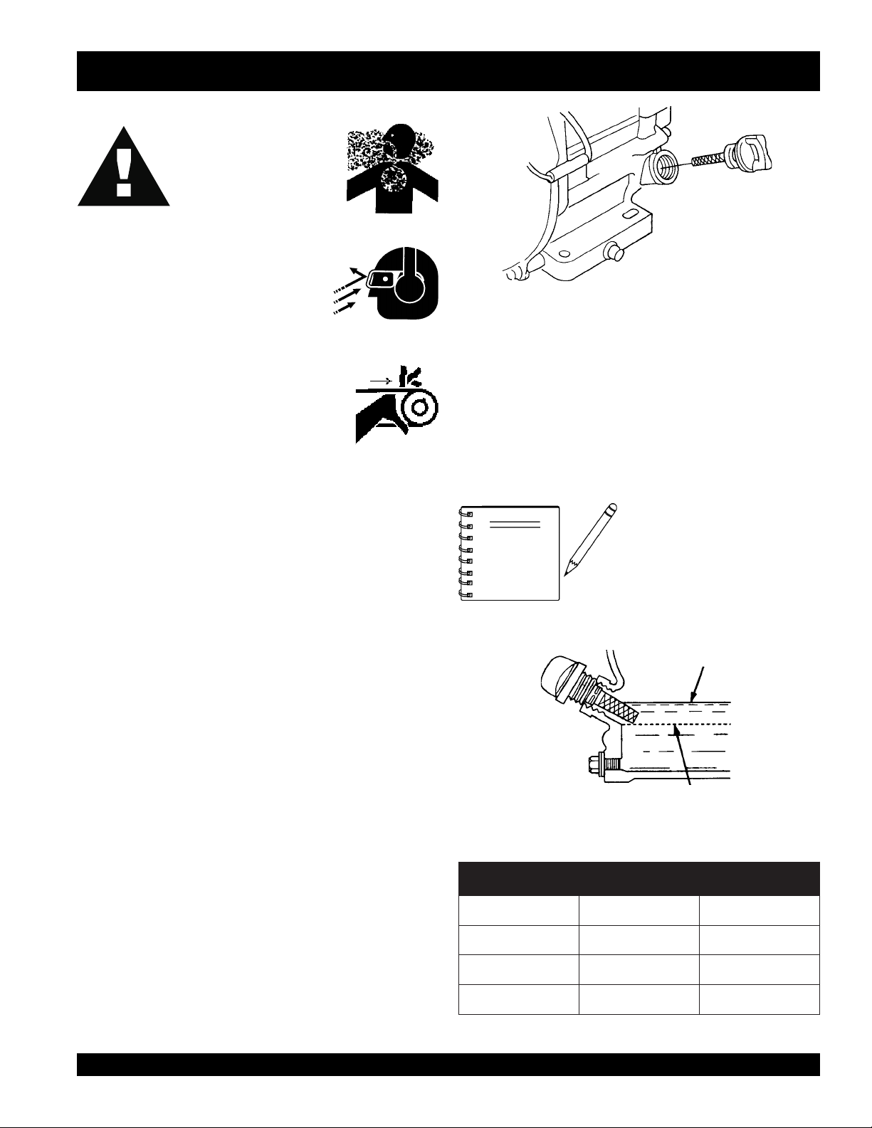
Figure 5. Engine Oil Dipstick (Removal)
3. Insert and remove the dipstick without screwing it into the filler
neck. Check the oil level shown on the dipstick.
4. If the oil level is low (Figure 6), fill to the edge of the oil filler
hole with the recommended oil type (Table 3). Maximum oil
capacity is 0.48 quarts (.45 liters)
Before Starting
1. Read safety instructions at the beginning of manual.
2. Clean the trowel, removing dirt and dust, particularly the
engine cooling air inlet, carburetor and air cleaner.
3. Check the air filter for dirt and dust. If air filter is dirty, replace
air filter with a new one as required.
4. Check carburetor for external dirt and dust. Clean with dry
compressed air.
5. Check fastening nuts and bolts for tightness.
Engine Oil Check
1. To check the engine oil level, place the trowel on secure
level ground with the engine stopped.
2. Remove the filler dipstick from the engine oil filler hole
(Figure 5) and wipe clean.
NOTE
Reference manufacturer engine
manual for specific servicing
instructions.
Figure 6. Engine Oil Dipstick (Oil Level)
epyTliO.3elbaT
nosaeS erutarepmeT epyTliO
remmuS rehgiHroC°52 03-W01EAS
llaF/gnirpS C°01~C°52 02/03-W01EAS
retniW rewoLroC°0 01-W01EAS
C-4 FINISHER WALK-BEHIND TROWEL — PARTS & OPERATION MANUAL — REV. #1 (07/24/02) — PAGE 19
Page 20
Explosive Fuel
C-4 FINISHER TROWEL— PRE-INSPECTION
V-Belt Check
A worn or damaged V-belt can adversely affect the performance
of the trowel. If a V-belt is defective or worn simply replace the Vbelt as outlined in the maintenance section of this manual.
Fuel Check
Motor fuels are highly flammable and can be dangerous if
mishandled. DO NOT smoke while refueling. DO NOT attempt
to refuel the trowel if the engine is
1. Remove the gasoline cap located on top of fuel tank.
2. Visually inspect to see if fuel level is low. If fuel is low, replenish
with unleaded fuel.
3. When refueling, be sure to use a strainer for filtration. DO
NOT top-off fuel. Wipe up any spilled fuel.
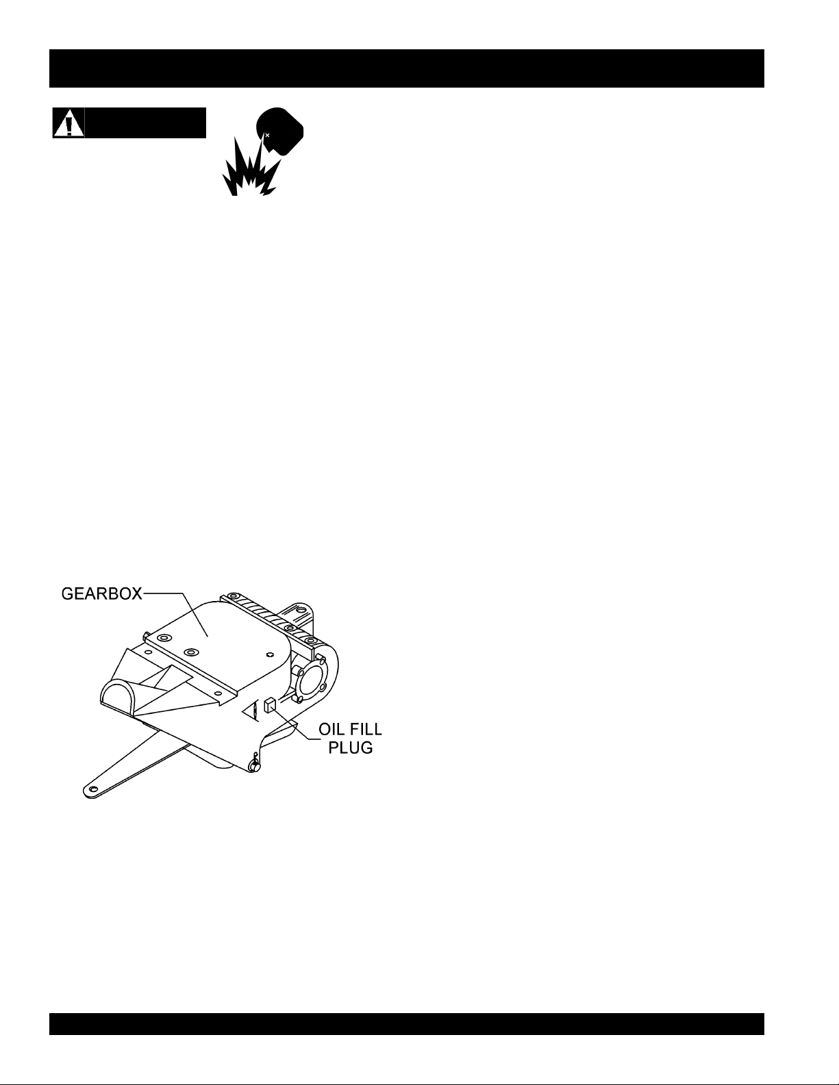
Gearbox Oil
1. Determine if the
plug located on the side of the gearbox. This plug will be
marked by the "
level of the lubrication oil should be to the bottom of the fill
plug.
gearbox
check
hot! or running
oil is low by removing the oil
" decal. See Figure 7. The correct
.
Blade Check
Check for worn or damaged blades. Check to see if one blade is
worn out while the others look new. If this is the case there could
be a blade pitch problem. Refer to the maintenance section of
this manual for blade pitch adjustment procedure. Replace any
worn blades.
CONTROLS
Hand Clutch
Some finisher models are equipped with a
. The unit automatically stops rotating when the clutch lever
clutch
is released. Clutch operation should be tested each time the
machine is started.
DO NOT let the machine sit unused with the engine at high speed
for an extended period of time. It will cause premature belt wear
or may destroy the belt. Always set the engine speed to idle when
the hand clutch is disengaged.
hand operated
Figure 7. Gearbox
2. If lubrication oil begins to seep out as the drain plug is
being removed, then it can be assumed that the gearbox
has a sufficient amount of oil.
3. If lubrication oil does not seep out as the drain plug is
being removed, fill with type ISO 680 (Whiteman P/N
10139) gearbox lubricant oil until the oil filler hole overflows.
PAGE 20 — C-4 FINISHER WALK-BEHIND TROWEL— PARTS & OPERATION MANUAL — REV. #0 (07/24/02)
Page 21
C-4 FINISHER TROWEL — INITIAL START-UP
Lifting the Trowel Onto a Slab.
Extra care should be taken when lifting the trowel off the ground.
Serious damage to the machine or personal injury could be
caused by dropping a trowel.
Even though the trowel is lightweight, always use two people
when lifting the trowel onto a slab of concrete or truck bed.
This section is intended to assist the operator with the initial
start-up of the walk-behind trowel. It is extremely important that
this section be read carefully before attempting to use the trowel
in the field.
DO NOT use your trowel until this section is thoroughly
understood
CAUTIONCAUTION
CAUTION
CAUTIONCAUTION
DO NOT attempt to operate the trowel until
the Safety, General Information and
Inspection sections of this manual have
been read and thoroughly understood.
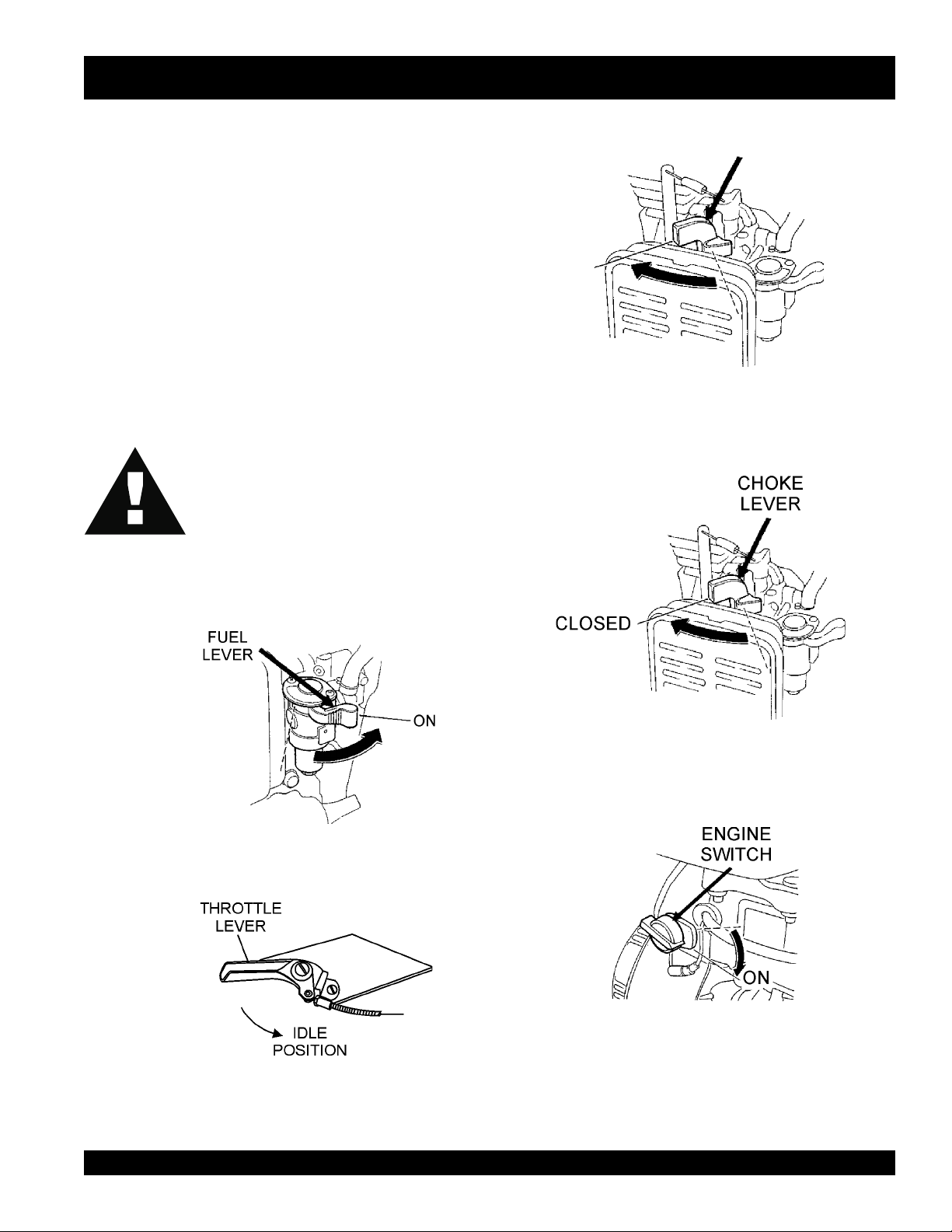
Starting the Engine (
HONDA
engine)
3. Place the
if starting a
4. Place the
if starting a
choke lever
cold
Figure 10. Engine Choke Lever (Open)
choke lever
warm engine
(Figure 10) in the "
engine.
(Figure 11) in the "
or the
OPEN
" position
CLOSED
temperature is warm.
" position
1. Place the engine
position.
Figure 8. Engine Fuel Valve Lever
2. Place the trowel's
position.
fuel valve lever
throttle lever
(Figure 8) to the "ON"
(Figure 9) to the "IDLE"
Figure 11. Engine Choke Lever (Closed)
5. Place the
Figure 12. Engine ON/OFF Switch (ON Position)
engine ON/OFF switch
(Figure 12) in the "
ON
"
Figure 9. Throttle Lever (Idle Position)
C-4 FINISHER WALK-BEHIND TROWEL — PARTS & OPERATION MANUAL — REV. #1 (07/24/02) — PAGE 21
Page 22
C-4 FINISHER TROWEL — INITIAL START-UP
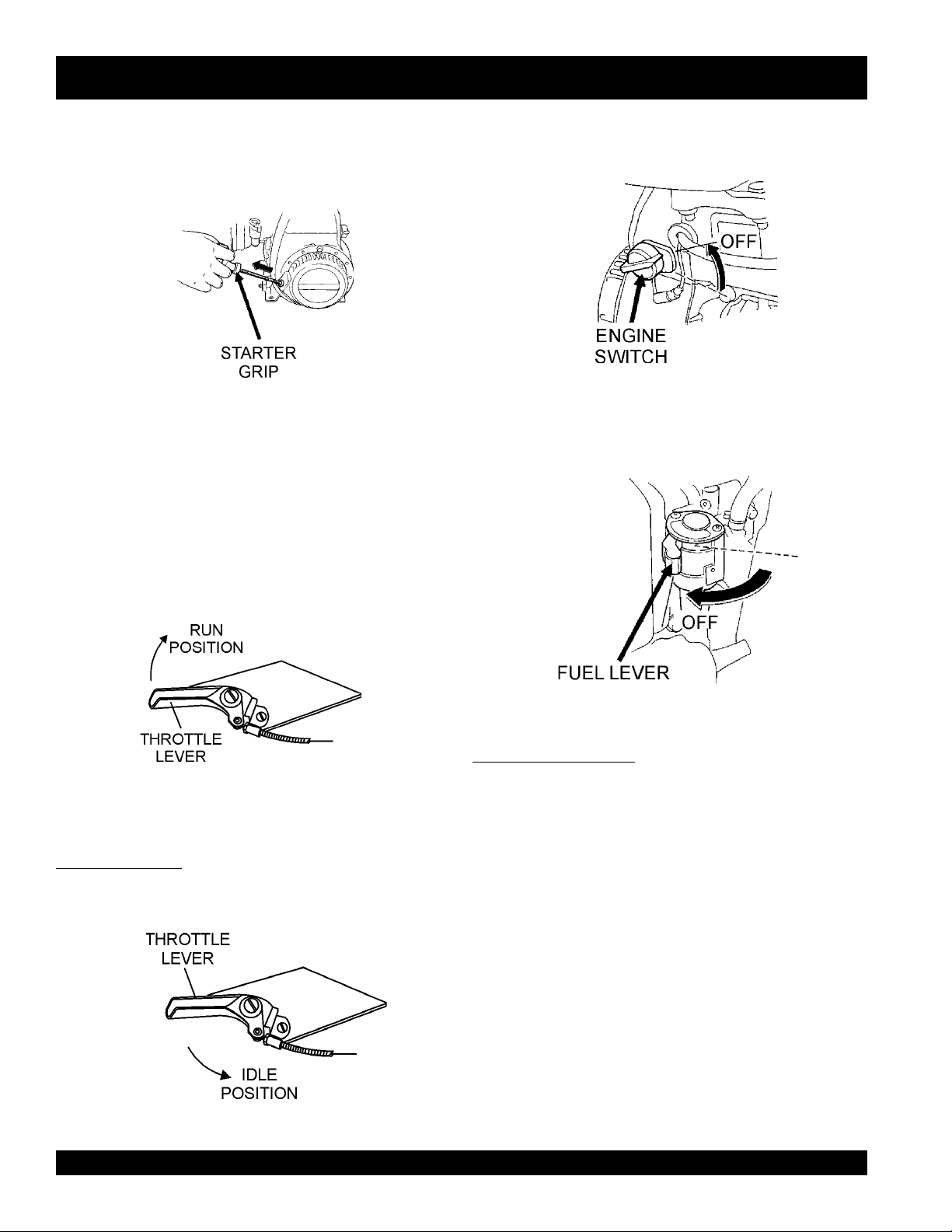
6. Grasp the starter grip (Figure 13) and slowly pull it out. The
resistance becomes the hardest at a certain position, corresponding to the compression point. Pull the starter grip briskly
and smoothly for starting.
Figure 13. Starter Grip
7. If the engine has started, slowly return the choke lever
(Figure 11 ) to the
started repeat steps 1 through 6.
Before the trowel is placed into operation, run the engine for
8.
several minutes. Check for fuel leaks, and noises that would
associate with a loose guard ring and/or covers.
CLOSED
position. If the engine has not
2. After the engine
“STOP” position (Figure 16 ).
3. Close the
valve lever to the CLOSED position.
cools
, turn the engine start/stop switch to the
Figure 16. Throttle Lever (Run Position)
fuel shut- off valve
(Figure 17) by moving the fuel
9. To begin troweling, place the throttle lever (Figure 14 ) in the
RUN
" position
"
Figure 14. Throttle Lever (Run Position)
Stopping The Engine
Normal Shutdown
1. Move the throttle lever to the IDLE position (Figure 15) and
run the engine for three minutes at low speed.
Figure 17. Throttle Lever (Run Position)
Emergency Showdown
1. Move the throttle lever quickly to the
the engine start/stop switch to the
IDLE
STOP
position.
position, and turn
Figure 15. Throttle Lever (Idle Position)
PAGE 22 — C-4 FINISHER WALK-BEHIND TROWEL— PARTS & OPERATION MANUAL — REV. #0 (07/24/02)
Page 23
C-4 FINISHER TROWEL — OPERATION
To maneuver the trowel, gently lift up on or press down on the
The following steps are intended as a basic guide to machine
operation, and are not to be considered a complete guide to
concrete finishing. We suggest that all operators (experienced
and novice) read “
Concrete Institute, Detroit, Michigan
section of this manual for more information.
Slabs on Grade
” published by the
. Read the “Training”
American
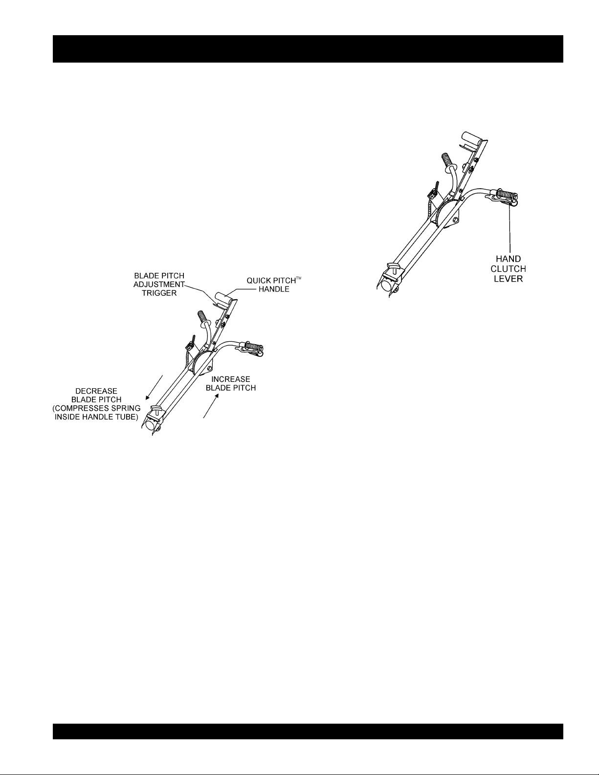
Pitching The Blades.
Quick Pitch Handle
2.
main trowel handle. To move the machine to the operator’s
left,
down
lift up
on the handle, to move machine to the right,
on the handle.
push
1. To pitch the blades upwards using the
handle
, (Figure 18) simply squeeze the trigger lock
"Quick Pitch
™"
and pull the handle towards the operator. Pushing the
handle towards the engine will cause the blades to lay
flat.
Figure 18. Quick Pitch™ Handle
Figure 19. Hand Clutch Lever
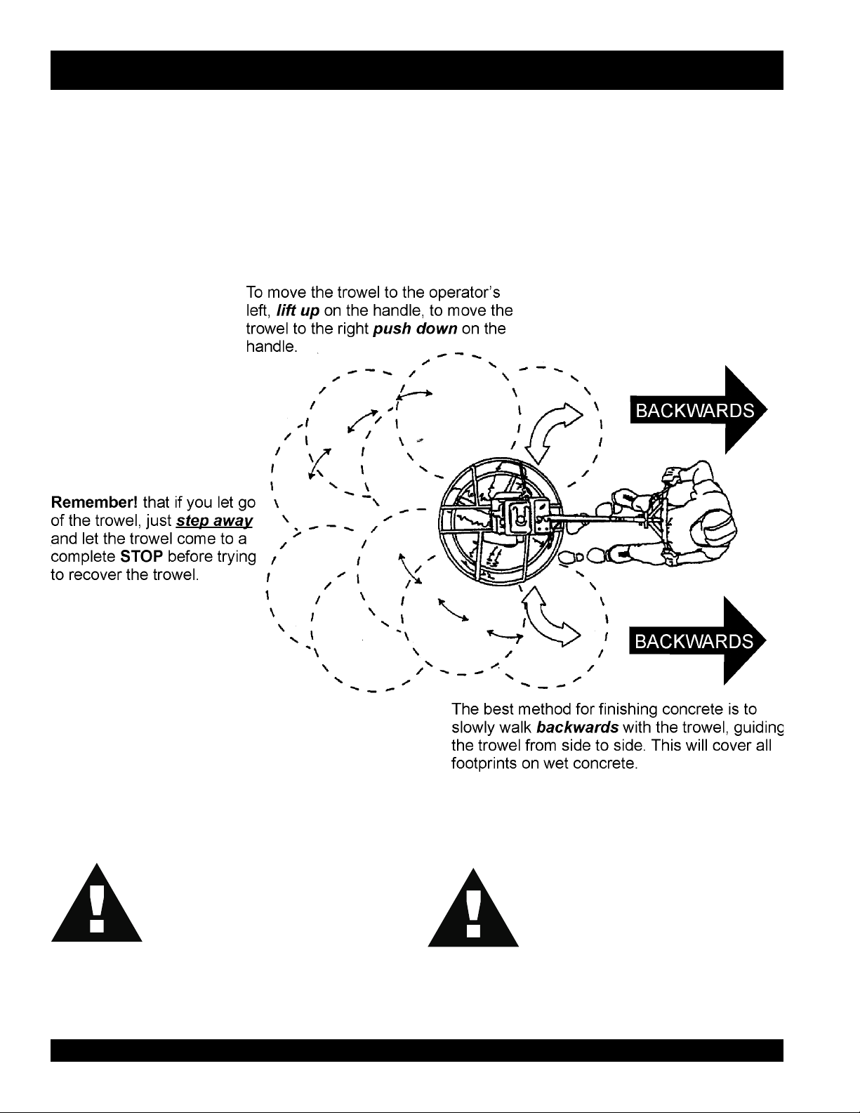
3. The best method for finishing concrete is to slowly walk
backwards (Figure 20) with the trowel, guiding the trowel
from side to side. This will cover all footprints on wet concrete.
4. Remember that if you let go of the trowel, just step away and
let the trowel come to a complete stop before trying to recover
the trowel.
Maneuvering the Trowel
Get into the operator’s position behind the handle. With a
1.
secure foothold and a firm grasp on the handles slowly
increase the engine speed until the desired blade speed is
obtained.
If your trowel has a
speed with the throttle, then pull on the hand clutch lever to
start the blades turning. Adjust the blade speed after the hand
clutch is fully engaged.
C-4 FINISHER WALK-BEHIND TROWEL — PARTS & OPERATION MANUAL — REV. #1 (07/24/02) — PAGE 23
hand clutch (Figure 19)
, set your engine
Page 24
C-4 FINISHER TROWEL — OPERATION
Figure 20 below illustrates a typical walk-behind trowel
application. Practice maneuvering the trowel. The trick is to let
the trowel do the work.
Continue to practice maneuvering the trowel. Try to practice as if
you were finishing a slab of concrete. Practice edging and
covering a large area. Remember a good finishing technique is
to work backwards. Be careful when moving backwards so that
hazards can be avoided. The best way to get accustomed to the
trowel is repeated use.
Figure 20. Maneuvering The Trowel
CAUTIONCAUTION
CAUTION
CAUTIONCAUTION
NEVER place your
guard rings while starting or operating this
equipment.
PAGE 24 — C-4 FINISHER WALK-BEHIND TROWEL— PARTS & OPERATION MANUAL — REV. #0 (07/24/02)
feet
or
hands
inside the
CAUTIONCAUTION
CAUTION
CAUTIONCAUTION
ALWAYS keep clear of
parts while operating this equipment.
rotating
or
moving
Page 25
C-4 FINISHER TROWEL — OPTIONS
Blades
Blades should be changed when
they fail to finish concrete in a
NOTE
Blades are a vital part of finishing concrete. This Whiteman
finisher has been designed to finish concrete and is built to
stringent quality standards out of the finest trowel steel. If you need
replacement blades, consult your parts list in this manual for part
numbers and order them from your Multiquip parts dealer or
importer.
Combo Blades
This trowel was equipped with
blades as original equipment. These blades have been designed
for optimum performance in both the floating and finishing of
concrete. These blades are versatile and should take care of most
troweling needs.
satisfactory manner.
combination type
(Figure 21)
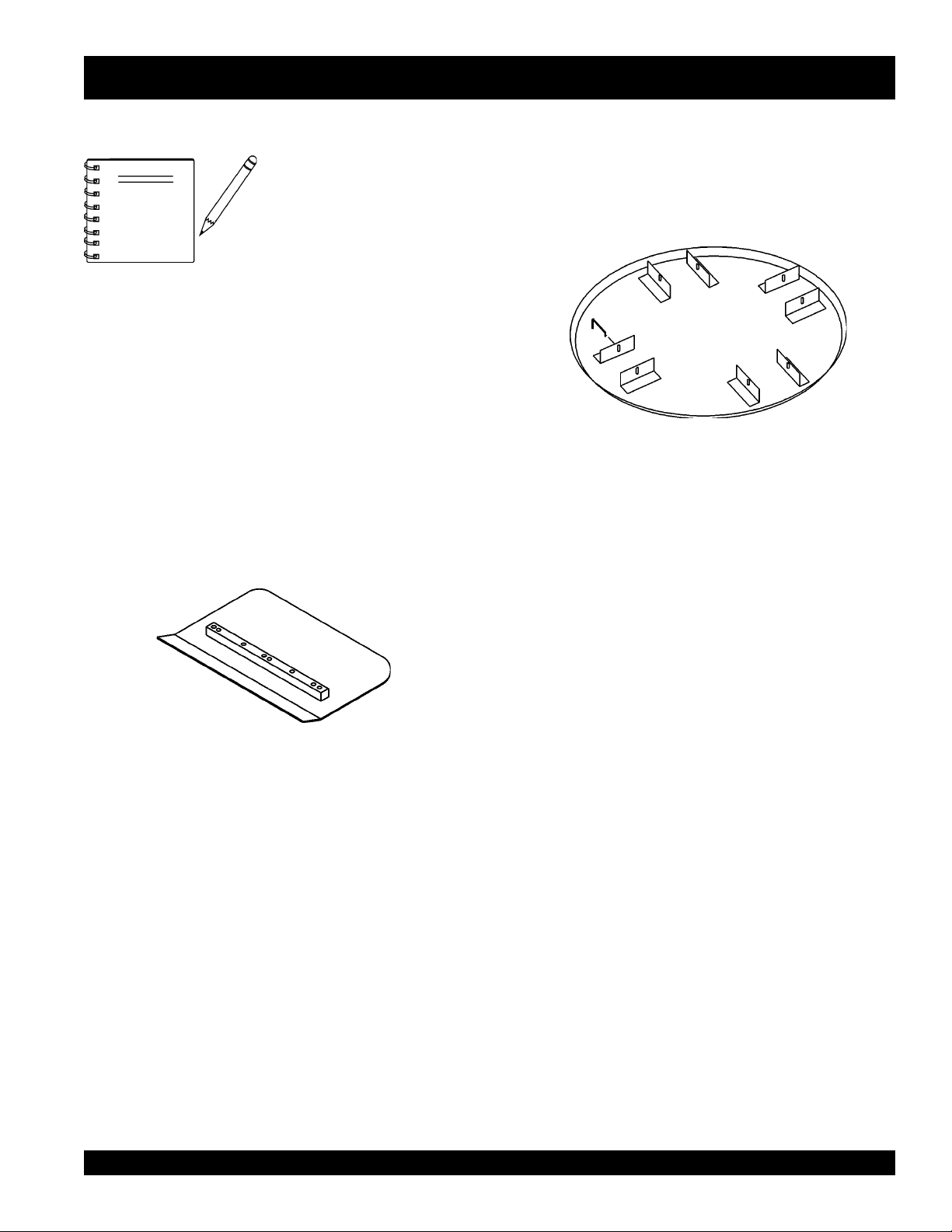
Float Discs (Optional)
These round discs (Figure 22) attach to the spiders and allow the
machine to “
floating and easy movement from wet to dry areas. They are also
very effective in embedding large aggregates and surface
hardeners.
float
” on “
wet
” concrete. The disc design allows early
Figure 22. Float Disk
Figure 21. Combination Blade
C-4 FINISHER WALK-BEHIND TROWEL — PARTS & OPERATION MANUAL — REV. #1 (07/24/02) — PAGE 25
Page 26
C-4 FINISHER TROWEL — MAINTENANCE
See the engine manual supplied
Trowel Arm adjustment Procedure
NOTE
with your machine for appropriate
engine maintenance schedule
and troubleshooting guide for
problems.
At the front of the book (Page 7) there is a “
Checklist
basis.
CAUTION!CAUTION!
CAUTION!
CAUTION!CAUTION!
ALWAYS allow the engine to cool before
servicing. NEVER attempt any maintenance work
on a
MAINTENANCE SCHEDULE
Daily (8-10 Hours)
1. Check the oil level in the engine crankcase and gear box,
2. Check V-belt.
Weekly (50-60 Hours)
1. Relube arms, thrust collar and clutch
”. Make copies of this checklist and use it on a daily
hot!
engine.
fill as necessary.
Daily Pre-Operation
NOTE
level
, clean area to test the trowel prior to and after is essential.
A
Any unlevel
will give an incorrect perception of adjustment. Ideally, a 5 x 5"
three-quarter inch thick
1. To determine which blades need adjustment, place the
trowel in the test area (three-quarter inch thick plate) and look
for the following conditions:
■
■
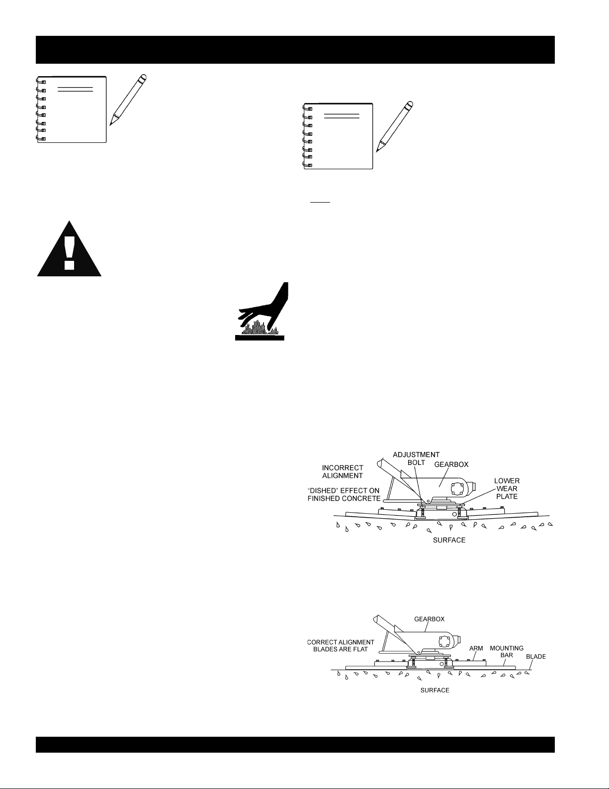
Figure 23 below illustrates a "
trowel arms
touching (0.10" max. clearance) lower wear plate. All alignment
bolts should be spaced the same distance from the lower wear
plate.
The following procedure should
be followed to adjust trowel arms
when it becomes apparent that
the trowel is finishing poorly or in
need of routine maintenance.
spots
in the floor or debris under the trowel blades
flat
steel plate should be used for testing.
Pitch the blades as flat as possible and look at the
adjustment bolts
with the
that one of them is not making contact, some adjustment
will be necessary.
Is the machine wearing out blades unevenly (i.e. one
blade is completely worn out while the others look new)?
lower wear plate
". Check to see that adjustment bolt is barely
. They should all barely make contact
on the spider. If you can see
worn spider bushings or bent
2. Replace blades if necessary.
3. Check and clean or replace the engine air filter as
necessary.
4. Replace engine oil and filter as necessary, see engine
manual.
Monthly (200-300 Hours)
1. Remove, clean, reinstall and relube the arms and thrust
collar. Adjust the blade arms.
2. Remove, clean, reinstall clutch
Yearly (2000-2500 Hours)
1. Check and replace if necessary the arm bushings, thrust
collar bushings and shaft seals.
2. Check pitch control cables for wear.
3. Adjust blade speed.
PAGE 26 — C-4 FINISHER WALK-BEHIND TROWEL— PARTS & OPERATION MANUAL — REV. #0 (07/24/02)
Figure 24 below illustrates the "
plate (as shipped from the factory).
Figure 24. Correct Spider Plate Alignment
Figure 23 Worn Spider Plate
correct alignment
" for a spider
Page 27

C-4 FINISHER TROWEL — MAINTENANCE
2. Start engine, and bring trowel blades up to full speed and look
for the following conditions:
■
Does the trowel have a perceived rolling or bouncing
motion when in use?
■
Look at the trowel while it is running, does the guard
ring “rock up and down” relative to the ground?
Spider Removal
1. Once it is determined that an adjustment is required, remove
the spider assembly from the gearbox shaft as follows:
a. Remove the zerk fitting and allen head screw desig-
nated by the letter "S" (Figure 25). In addition, on the
opposite side of the spider block there is another zerk
fitting and allen head screw, remove both of these
components.
b. Lift the upper trowel assembly off the spider assembly.
Trowel Arm Removal
1. Remove the two remaining zerk fittings and allen head
screws from the spider assembly (Figure 26).
Trowel Blade Removal
A slight tap with a rubber mallet may be necessary to
dislodge the spider from the main shaft of the gearbox.
Figure 26. Trowel Arms Removal
1. Remove the trowel blades from the trowel arm by removing
the two hex head bolts (Figure 27) from the trowel arm. Set
blades aside.
Figure 27. Trowel Blades
Wire brush
2.
trowel arm. Repeat this for the remaining three arms.
any build-up of concrete from all six sides of the
Figure 25. Spider/Gearbox Removal
C-4 FINISHER WALK-BEHIND TROWEL — PARTS & OPERATION MANUAL — REV. #1 (07/24/02) — PAGE 27
Page 28

C-4 FINISHER TROWEL — MAINTENANCE
Trowel Arm Flatness Test
1. Using a piece of 3/4 inch thick steel plate or any surface which
true
and
flat
is
flatness.
2. Check each of the six sides of the trowel arm (hex section
only) using a ten thousands of an inch (max.) feeler gauge
(Figure 28) between the flat of the trowel arm and an
tremely flat
, check all
test surface.
six sides
of each trowel arm for
Re-Assembly
1. Clean and examine the
thrust collar bushing
Wire brush any concrete or rust build-up. If any of the spider
components are found to be damaged or out of round,
replace them.
2. Insert all trowel arms (4) into spider plate.
ex
-
3. Lock trowel arms in place by tightening the hex head zerk
grease fittings (4) and allen head screws (2).
4. Re-install the blades back onto the trowel arms.
5. Reinstall lower wear plate,
bearing
onto the spider shaft. Make sure that there is little or no lateral
movement between the thrust collar and the spider shaft.
6. Carefully lift
way on gear box main shaft and insert into spider assembly.
7. Lubricate all grease points (zerk fittings) with premium
Lithum 12"
"
consistency.
lower wear plate, thrust collar
. Examine the entire spider assembly.
thrust collar
in the
reverse order
the upper trowel assembly
based grease, conforming to NLG1 Grade #2
that they were dis-assembled
and
thrust collar
, line up the key-
and
Figure 28. Trowel Arm Flatness Test
3. If the trowel arm is found to be
trowel arm. A bent trowel will not allow the trowel to operate
in a smooth fluid rotation.
4. Next, check each of the six sides of the round machined shaft
section of the trowel arm. Each section should have the
clearance
test surface.
between the round of the trowel arm shaft and the
uneven
or
bent
, replace the
same
Trowel arms can be
damaged by rough
handling or by striking
NOTE
exposed plumbing or
forms while in operation.
ALWAYS
look-out for
objects which might
cause damage to the
trowel arms.
PAGE 28 — C-4 FINISHER WALK-BEHIND TROWEL— PARTS & OPERATION MANUAL — REV. #0 (07/24/02)
Page 29

Changing a Blade
C-4 FINISHER TROWEL — MAINTENANCE
Whiteman recommends that
same time
the blades are changed at one time.
1. Place the machine on a flat, level surface. Adjust the blade
. The machine may wobble or bounce if only some of
pitch control to make the blades as flat as possible. Note the
blade orientation on the trowel arm.
all the blades be changed at the
Before removing the blades,
please note the orientation
NOTE
1. Remove the two bolts and lock washers that secure the blade
to the trowel arm. Remove the blade.
2. Using a wire brush, scrape all concrete particles and foreign
debris from the trowel arm.
3. Install the new trowel blade onto the trowel arm. Make sure
blade is installed correctly, maintaining the proper orientation for direction of rotation
4. Reinstall
blade to the trowel arm. Tighten both bolts securely.
5. Repeat steps 1-4 for all remaining blades.
Hand Clutch Adjustment
This trowel is equipped with a hand-operated clutch that is a belttightener type clutch. It operates by removing
which then transmits power from the engine to the gearbox.
There are two reasons to adjust the hand clutch: 1) operator
comfort; 2) initial belt stretch and break-in.
The easiest and most simple adjustment is to adjust the clutch
cable housing using the adjustment nut (Figure 29) located on the
clutch lever. Rotating the nut provides either more or less
(depending upon the direction of rotation) clutch engagement.
the two bolts and lock washers that secure the
of the blade on the trowel
arm.
.
slack
in the V-belt
Hand Clutch Disengagement
1. Start the trowel as outlined in the "
in this manual. Move the throttle lever so that the engine is
running about 1/4 to 1/3 of full speed.
2. Grip the trowel handle firmly and carefully engage the clutch
by squeezing the clutch lever toward the handle with your left
hand. After the trowel is stabilized and you feel comfortable
with its operation, use your right hand to adjust the housing
adjustment nut.
3.
Rotating the nut so that it backs out of the lever housing
increases the engagement and also the squeezing force
required to keep it engaged.
Too much squeezing force may cause premature hand
fatigue. Too little squeezing force may cause belt slippage
and premature belt wear. Each operator should experiment
with the adjustment to get the optimum combination of
squeeze force and belt grip.
4. After initial break-in (approximately 8 hours) the above
procedure should be repeated to attain optimum operator
comfort and belt wear.
After considerable belt wear, the adjustments mentioned
5.
above may have a little or no effect on clutch engagement. If
this is the case, the belt should be replaced.
Figure 29. Trowel Arm Adjustment Tool
Initial Start-up
" section"
C-4 FINISHER WALK-BEHIND TROWEL — PARTS & OPERATION MANUAL — REV. #1 (07/24/02) — PAGE 29
Page 30

C-4 FINISHER TROWEL — TROUBLESHOOTING (TROWEL)
GNITOOHSELBUORT.4ELBAT
MOTPMYS MELBORPELBISSOP NOITULOS
?noitcnuflamhctiwslliK .yrassecenfihctiwsecalperroNOsihctiwsllikehttahterusekaM
.lla
tatonrohguorgninnurenignE
.gninoitcnuftonhctiwsllikytefaS
nislriwsnevenusekamro
.”etercnoc
?leuF
?noitingI
?smelborprehtO .launams’rerutcafunamenignetlusnoC
?snoitcennoceriwesooL .yrassecensaecalpeR.gniriwkcehC
?stcatnocdaB .hctiwsecalpeR
?sedalB
?redipS
?smraleworttneB
,etercnocsllor,secnuob“lewortfI
?sgnihsubmraleworT
.yltcerrocgninoitcnuf
.rabedalbehtotlellarap
.yletaidemmitiecalper,tnebylthgilsnevesi
otdeilppusgniebleufsierehterusekaM.metsysleufehttakooL
.deggolctonsiretlifleufehttahterusneotkcehC.enigneeht
sidnarewopsahhctiwsnoitingiehttahterusneotkcehC
.nrowylevissecxeton,noitidnocdoognierasedalbniatrecekaM
ehtmorf)mm05("2nahtsselonerusaemdluohssedalbhsiniF
onerusaemdluohssedalbobmoc,egdegniliartehtotrabedalb
dnathgiartsebdluohsedalbfoegdegniliarT.)mm98("5.3tahtssel
derusaemsaelgnahctipemasehttateserasedalbllatahtkcehC
thgiehrofelbaliavasiloottnemtsujdadleifA.redipsehtta
.)tnempiuqElanoitpOees(smralewortehtfotnemtsujda
smraehtfoenofI.smraleworttnebrofylbmessaredipsehtkcehC
ybenodebnacsihT.ssenthgitrofsgnihsubmralewortehtkcehC
2.3("8/1nahteromsierehtfI.nwoddnapusmralewortehtgnivom
ebdluohssgnihsubeht,mraehtfopitehttalevartfo)mm
.emitemasehttadecalperebdluohssgnihsubllA.decalper
?ralloctsurhT
?gnihsubralloctsurhT
?nrowgniraebtsurhT
?tfahsniaM
.tniop
.gninnurelihwnoitom
gnillorelbitpecrepasahenihcaM
?ekoY
?hctiPedalB
.ralloctsurhtehtnignihsubeht
.yrassecenfiecalper,pac
.yrassecensaekoyecalpeR.pacraeweht
.ralloctsurhtehtecalper)mm5.0("20.0nahteromybseiravti
ebtonnacdnathgiartsnurtsumtfahsniamehT.ssenthgiartsrof
.launamninoitcesecnanetniamreptsujdA.sedalbrehtollasa
PAGE 30 — C-4 FINISHER WALK-BEHIND TROWEL— PARTS & OPERATION MANUAL — REV. #0 (07/24/02)
fI.redipsehtnotignitatorybralloctsurhtehtfossentalfehtkcehC
eromtlitnactifI.redipsehtnotignikcorybralloctsurhtehtkcehC
ecalper,].D.Oralloctsurhtehttaderusaemsa[)mm4.2("23/3naht
tsurhT:etoN.eerfgninnipssititahteesotgniraebtsurhtehtkcehC
dekcehcebdluohsylbmessaxobraegehtfotfahstuptuoniamehT
tnemhcattaredipsehttadnuorfotuo)mm80.0("300.0nahterom
noylnevesserpekoyehtfosregnifhtobtahterusekamotkcehC
hctipemasehtevahotdetsujdasiedalbhcaetahterusneotkcehC
Page 31

C-4 FINISHER TROWEL — TROUBLESHOOTING (TROWEL)
)DEUNITNOC(GNITOOHSELBUORT.4ELBAT
MOTPMYS MELBORPELBISSOP NOITULOS
?stleb-VnroW tleb-VecalpeR
?hctulclagufirtnecytriD .hctulcnaelcdnaelbmessasiD
lagufirtnectuonrowroevitcefeD
?hctulc
hsiggulsrognippilshctulC
deepsenigneotesnopser
.egnahc
?strap
?xobraeg
?tnemtsujdafotuohctulcdnaH .launamsihtfonoitcesecnanetniamnisnoitcurtsnireptsujdA
hctulcdnahevitcefefronroW
?xobraegnisgniraebnroW
nisraegnekorbronroW
.hctulceritneecalpeR
.yrassecensastrapecalpeR
ehtkcehc,ytluciffidhtiwsetatortfahsfI.dnahybtfahstupnietatoR
.yrassecensaecalpeR.sgniraebtfahstuptuodnatupni
.detatorsitfahstupniehtnehwsetatortfahsxobraegehttahtyfireV
.tesasaraegmrowdnamrowehthtobecalpeR
C-4 FINISHER WALK-BEHIND TROWEL — PARTS & OPERATION MANUAL — REV. #1 (07/24/02) — PAGE 31
Page 32

C-4 FINISHER TROWEL — TROUBLESHOOTING (ENGINE)
)ENIGNE(GNITOOHSELBUORT.5ELBAT
MOTPMYSESUACELBISSOPNOITULOS
?gnigdirbgulpkrapS
ontub,elbaliavasileuf",tratsottluciffiD
."gulpkrapstaKRAPS
?noitalusni
?evitcefedliocnoitingI.liocnoitingiecalpeR
dna,elbaliavasileuf",tratsottluciffiD
."gulpkrapsehttatneserpsiKRAPS
?gnitiucric
?epytleufgnorW
?gulpkrapsnotisopednobraC .gulpkrapsecalperronaelC
gulpkrapstneicifedoteudtiucrictrohS
?paggulpkrapsreporpmI.pagreporpotteS
?detrohssihctiwsFFO/NO
?yrtridstniop,pagkrapsreporpmI
trohsronrownoitalusniresnednoC
?gnitiucrictrohsronekorberiwgulpkrapS
.gulpkraps
.nrowfiecalper
.hctiws
.stniop
.resnednocecalpeR
.gniriw
ecalperronoitalusni,pagkcehC
,noitalusnigulpkrapskcehC
ecalper,gniriwhctiwskcehC
naelcdnapagkrapstcerrocteS
gulpkrapsevitcefedecalpeR
ecalperdna,metsysleufhsulF
.leuffoepyttcerrochtiw
kraps,elbaliavasileuf",tratsottluciffiD
"lamronsinoisserpmocdnatneserpsi
?ytridrenaelcriA .renaelcriaecalperronaelC
?nepOekohC.ekohCesolC
kraps,elbaliavasileuf",tratsottluciffiD
"wolsinoisserpmocdnatneserpsi
?ylreporpdenethgit
?degamad
?deggolcretlifleuF.retlifleufecalpeR
.blubgnimirpedisnitneserpleufoN
?enilleufniriA.enilleufdeelB
?metsysleufnitsudroretaW.metsysleufhsulF
?dedurtorprokcutsevlavtsuahxe/noitcuS.sevlavtaes-eR
?nrowrednilycro/dnagnirnotsiP
tongulpkrapsro/dnadaehrednilyC
teksaggulpkrapsro/dnateksagdaeH
?knatleufnielbaliavatonleuF.leuffoepyttcerrochtiwlliF
?deggolcelohrehtaerbpacknatleuF .packnatleufecalperronaelC
rodnasgnirnotsipecalpeR
.notsip
dnastlobdaehrednilyceuqroT
.gulpkraps
gulpkrapsdnadaehecalpeR
.steksag
PAGE 32 — C-4 FINISHER WALK-BEHIND TROWEL— PARTS & OPERATION MANUAL — REV. #0 (07/24/02)
Page 33

NOTE PAGE
C-4 FINISHER WALK-BEHIND TROWEL — PARTS & OPERATION MANUAL — REV. #1 (07/24/02) — PAGE 33
Page 34

C-4 FINISHER TROWEL — EXPLANATION OF CODES IN REMARKS
How to read the marks and remarks used in this parts book.
Section 1: Items Found In the “Remarks” Column
Serial Numbers-Where indicated, this indicates a serial
number range (inclusive) where a particular part is used.
Model Number-Where indicated, this shows that the
corresponding part is utilized only with this specific model
number or model number variant.
Section 2: Items Found In the “Remarks” Column
Serial Numbers-Where indicated, this indicates a serial number
range (inclusive) where a particular part is used.
Model Number-Where indicated, this shows that the
corresponding part is utilized only with this specific model number
or model number variant.
Section 3: Items Found In the “Items Number” Column
All parts with same symbol in the number column,
■
, belong to the same assembly or kit.
, #, +, %, or
*
COLUMN
Note: If more than one of the same reference number is listed,
the last one listed indicates newest (or latest) part available.
NOTE
The contents of this parts
catalog are subject to
change without notice.
PAGE 34 — C-4 FINISHER WALK-BEHIND TROWEL— PARTS & OPERATION MANUAL — REV. #0 (07/24/02)
Page 35

C-4 FINISHER TROWEL — SUGGESTED SPARE PARTS
C-4 FINISHER TROWEL 1 TO 3 UNITS WITH
HONDA G100K2QA2 ENGINE.
1 to 3 Units
Qty......... P/N .............................. Description
3 ............ 0189 ...................... GRIP
4 ............ 1162 A .................. LUBE CAP
4 ............ 1167 A .................. SCREW
4 ............ 1456 ...................... NUT
4 ............ 1875 ...................... WASHER
4 ............ 1322 ...................... SCREW
1 ............ 2614 ...................... GASKET KIT
1 ............ 2616 ...................... BEARING KIT
2 ............ 9807354776 .......... SPARK PLUG HONDA
2 ............ 17631ZH7003 ....... TANK CAP (HONDA)
3 ............ 17211896000 ........ AIR CLEANER ELEMENT (HONDA)
2 ............ 17218ZE2505 ....... FILTER OUTER (HONDA)
2 ............ 10652 .................... PITCH CABLE
1 ............ 10607 .................... THRUST BEARING
1 ............ 10567 .................... THRUST COLLAR
1 ............ 10639 .................... WEAR PLATE
4 ............ 10611 .................... V-BELT (A-21)
C-4 FINISHER WALK-BEHIND TROWEL — PARTS & OPERATION MANUAL — REV. #1 (07/24/02) — PAGE 35
Page 36

NAMEPLATE AND DECALS
C-4 FINISHER TROWEL — NAMEPLATE AND DECALS
PAGE 36 — C-4 FINISHER WALK-BEHIND TROWEL— PARTS & OPERATION MANUAL — REV. #0 (07/24/02)
Page 37

C-4 FINISHER TROWEL — NAMEPLATE AND DECALS
NAMEPLATE AND DECALS
NO. PART NO. PART NAME QTY. REMARKS
1 10732 DECAL: CAUTION PITCH HANDLE 1
2 11246 DECAL: BELT DRIVE ........................................... 1 ....... PART OF DECAL KIT 12620
3 11246 DECAL: GEAR DRIVE .......................................... 1 ....... PART OF DECAL KIT 12620
4 11246 DECAL: COUNTER CLOCKWISE......................... 1 ....... PART OF DECAL KIT 12620
5 1848 DECAL: MQ/WHITEMAN LOGO 1
6 11246 DECAL: CHECK OIL ............................................. 1 ....... PART OF DECAL KIT 12620
7 DECAL: NAME PLATE .......................................... 1 ....... CONTACT MULTIQUIP
.......................................................................................... PARTS DEPARTMENT
8 11247 DECAL: HELMET, FOOT AND GLOVE ................. 1 ....... PART OF DECAL KIT P/N 12620
9 11246 DECAL: HEAT ....................................................... 1 ....... PART OF DECAL KIT P/N 12620
SEE DECAL ILLUSTRATIONS ON PAGE 12
C-4 FINISHER WALK-BEHIND TROWEL — PARTS & OPERATION MANUAL — REV. #1 (07/24/02) — PAGE 37
Page 38

C-4 FINISHER TROWEL — QUICK PITCH™ HANDLE ASSY.
QUICK PITCH ™ HANDLE ASSY.
PAGE 38 — C-4 FINISHER WALK-BEHIND TROWEL— PARTS & OPERATION MANUAL — REV. #0 (07/24/02)
Page 39

C-4 FINISHER TROWEL — QUICK PITCH™ HANDLE ASSY.
QUICK PITCH ™ HANDLE ASSY.
NO. PART NO. PART NAME QTY. REMARKS
1 10657 PITCH CONTROL HANDLE 1
2 10881 LATCHING BAR 1
3 3910382 SHOULDER BOLT 3/8 X 3/8 1
4 10655 LATCH RETURN SPRING COVER 1
5 10654 LATCH RETURN SPRING 1
6 10659 QP LATCHING BOLT 1
6 10878 QP LATCHING BOLT 1
7 0161C LOCK WASHER 5/16” 1
8 10024 LOCK NUT 1/4- 20 1
9 10652 PITCH CONTROL CABLE 1
10 10658 CONTROL HANDLE SUPPORT TUBE 1
11 0189 HANDLE GRIP 1
12 0304 RHMS 10- 24 X 1/4” 2
13 0302 THROTTLE ASSEMBLY CABLE 1
14 5283 LOCK NUT 5/16- 18 1
15 10651 STAR WHEEL 1
16 1456 HEX FINISH NUT 3/8- 16 1
17 3216 COTTER PIN 3
18 0948 FLAT WASHER 1/4” 2
19 10629 HANDLE HINGE PIN 1
20 10133 LOCK NUT 3/8- 16 2
21 10136 FLAT WASHER 3/8” 3
22 1117 SUPPORT BLOCK 1
23 1121 HHCS 3/8- 16 X 2.3/4” 2
24 10701 SWING BOLT 1
25 5291 CLEVIS PIN 1
26 0300B FLAT WASHER 5/16” 2
27 0669A HHCS 5/16- 18 X 2.1/4” 1
28 1512 CLUTCH HAND LEVER 1
29 10843 PAD 1
30 10036 CLUTCH ASSIST HANDLE ASSY.. 1
31 10660 SHIM 1
32 3164 FHSCS 1/4- 20 X 1” 1
33 10634 LOWER HANDLE 1
34 10635 UPPER HANDLE 1
35 10653 CLUTCH CABLE ASSY.. 1
36 10676 ACORN NUT 5/16- 18 1
37 8128 CLAMP 2
39 11015 HANDLE SLIDER 1
C-4 FINISHER WALK-BEHIND TROWEL — PARTS & OPERATION MANUAL — REV. #1 (07/24/02) — PAGE 39
Page 40

SPIDER ASSY.
C-4 FINISHER TROWEL — SPIDER ASSY.
PAGE 40 — C-4 FINISHER WALK-BEHIND TROWEL— PARTS & OPERATION MANUAL — REV. #0 (07/24/02)
Page 41

C-4 FINISHER TROWEL — SPIDER ASSY.
SPIDER ASSY.
NO. PART NO. PART NAME QTY. REMARKS
1 10640 YOKE 1
2 10662 YOKE PIN 1
3 5117 COTTER PIN 2
4 0948 FLAT WASHER 1/4” 2
5 10607 THRUST BEARING 1
6 10567 THRUST COLLAR 1
7 10639 WEAR PLATE 1
8 10563 SPIDER 1
9 0164B HHCS 3/8- 16 X 1.1/4” F.T. 4
10 1876 JAM NUT 3/8- 16 4
11 0166A LOCK WASHER 3/8” 4
12 0181B LOCK WASHER 1/4” 8
13 10585 TROWEL ARM.................................................. 4.................TO ME34571
13 10768 TROWEL ARM.................................................. 4.................FROM ME34572
14 10790 HHCSM6- 1 X 30MM 8
15 0685 SHSS 5/16- 18 X 5/16” 2
16 1162A GREASE ZERK CAP 4
17 10587 ARM RETAINING SCREW 4
18 1875 INT. SHKP. WASHER 3/8” 4
19 0244 COMBO BLADE ASM. 4
20 10698 ADJUSTING NUT 5/16- 18 1
23 10687 BLADE ASM. (WITH SCREWS & NUTS) 4
24 1116 BRASS JAM NUT 5/16- 18 1
C-4 FINISHER WALK-BEHIND TROWEL — PARTS & OPERATION MANUAL — REV. #1 (07/24/02) — PAGE 41
Page 42

GEARBOX ASSY.
C-4 FINISHER TROWEL — GEARBOX ASSY.
PAGE 42 — C-4 FINISHER WALK-BEHIND TROWEL— PARTS & OPERATION MANUAL — REV. #0 (07/24/02)
Page 43

C-4 FINISHER TROWEL — GEARBOX ASSY.
GEARBOX ASSY.
NO. PART NO. PART NAME QTY. REMARKS
1
*
2
*
3
*
4
*
5
*
6
*
7
*
8
*
9
*
10 0627 SQUARE KEY 3/16 X 3/16 X 1.1/4” 1
11
12
13
14
15
16
17
18
19
20 10686 GEARBOX ASSY. .................................... 1 ................ INCLUDES ITEMS W/
21
22
23
24
25
26 2616 BEARING REPLACEMENT KIT ..............1 ................ INCLUDES ITEMS W/%
10583 GEAR CASE 1
0131A HHCS 1/4- 20 X 3/4 8
1136 END CAP 1
2614 GASKET KIT
% 0735A BEARING CUP 2
1132 AIR VENT 1
% 0735 BEARING CONE 2
1828 WORM & COUNTER SHAFT 1
2308 O- RING 2
0753 OIL SEAL 1
*
1133 FLANGE 1
*
1139 WOODRUFF KEY #21 2
*
0121A SQUARE HEAD PIPE PLUG 3/8” 1
*
% 0232A BEARING CUP 2
*
% 0232 BEARING CONE 2
*
1138 RETAINING RING 1
*
1202 BRONZE GEAR 1
*
10580 MAIN SHAFT 1
*
1145 COVER PLATE 1
*
0254 OIL SEAL 1
*
1146 FHSCS 5/16- 18 X 1” 4
*
10235 EXT. SHKP. LOCK WASHER 5/16” 4
*
1143 SEAL RING 1
*
*
C-4 FINISHER WALK-BEHIND TROWEL — PARTS & OPERATION MANUAL — REV. #1 (07/24/02) — PAGE 43
Page 44

C-4 FINISHER TROWEL — ENGINE, 2.5 HP HONDA ASSY.
ENGINE, 2.5 HP HONDA ASSY.
PAGE 44 — C-4 FINISHER WALK-BEHIND TROWEL— PARTS & OPERATION MANUAL — REV. #0 (07/24/02)
Page 45

C-4 FINISHER TROWEL — ENGINE, 2.5 HP HONDA ASSY.
ENGINE, 2.5 HP HONDA ASSY.
NO. PART NO. PART NAME QTY. REMARKS
1 10649 ENGINE, 2.8 HP. HONDA G100 1
2 0202 HHCS 5/16- 18 X 1” 1
3 0161C LOCK WASHER 5/16” 5
4 0300B FLAT WASHER 5/16” 5
5 0205 HHCS 3/8- 16 X 1” 1
6 0166A LOCK WASHER 3/8” 1
7 10136 FLAT WASHER 3/8” 1
8 0655 HHCS 5/16- 18 X 3/4” 2
9 10644 CLUTCH BRACKET 1
10 5277 HHCS 1/4- 20 X 1.1/2” 1
11 2866 HHCS M8- 1.25 X 20MM 2
12 10282 SHOULDER BOLT 3/8 X 1” 1
13 10608 IDLER PULLEY 1
14 10370 HEX NUT M8- 1.25 1
15 10611 BELT (A21) 1
16 0730 HHCS 1/4- 20 X 1” 3
17 0181B LOCK WASHER 1/4” 5
18 10661 BELT GUARD 1
19 10609 PULLEY 1
20 2126 SQUARE KEY 3/16 X 3/16 X 13/16” 1
21 1605 HHCSM8- 1.25 X 25MM 1
22 10641 CLUTCH LEVER 1
23 10610 PULLEY 1
24 0948 FLAT WASHER 1/4” 5
25 1579 HHCS 1/4- 20 X 1/2” 2
26 10740 BELT TENSIONING SHOE 1
27 10450 SHSS 10- 32 X 1/4” 1
28 0949 HEX NUT 1/4- 20 1
C-4 FINISHER WALK-BEHIND TROWEL — PARTS & OPERATION MANUAL — REV. #1 (07/24/02) — PAGE 45
Page 46

GUARD RING ASSY.
C-4 FINISHER TROWEL — GUARD RING ASSY.
PAGE 46 — C-4 FINISHER WALK-BEHIND TROWEL— PARTS & OPERATION MANUAL — REV. #0 (07/24/02)
Page 47

C-4 FINISHER TROWEL — GUARD RING ASSY.
GUARD RING ASSY.
NO. PART NO. PART NAME QTY. REMARKS
11 0166A LOCK WASHER 3/8" 4
21 0205 HHCS 3/8-16x1: 4
22 10602 GUARD RING 1
C-4 FINISHER WALK-BEHIND TROWEL — PARTS & OPERATION MANUAL — REV. #1 (07/24/02) — PAGE 47
Page 48

C-4 FINISHER TROWEL — BLADES & ADJUSTMENT FIXTURE ASSY.
BLADES & ADJUSTMENT FIXTURE ASSY.
(OPTIONS)
PAGE 48 — C-4 FINISHER WALK-BEHIND TROWEL— PARTS & OPERATION MANUAL — REV. #0 (07/24/02)
Page 49

C-4 FINISHER TROWEL — BLADES & ADJUSTMENT FIXTURE ASSY.
BLADES & ADJUSTMENT FIXTURE ASSY.
NO. PART NO. PART NAME QTY. REMARKS
20 COMBO FLOAT & FINISH BLADE .......................... 4 ......... CONTACT UNIT SALES DEPT./ACCESSORY ITEM
20 ENDURO COMBO FLOAT &FINISH BLADE .......... 4 ......... CONTACT UNIT SALES DEPT./ACCESSORY ITEM
21 FLOAT BLADE ........................................................ 4 ......... CONTACT UNIT SALES DEPT./ACCESSORY ITEM
22 FINISH BLADE ....................................................... 4 ......... CONTACT UNIT SALES DEPT./ACCESSORY ITEM
22 ENDURO FINISH BLADE W/ROTATING ................ 4 ......... CONTACT UNIT SALES DEPT./ACCESSORY ITEM
23 0202 HHCS 5/16-18X1" RING 4
24 0201 GUARD RING LUG RING 4
26 1434 TROWEL LUG (FINISH BLADE ONLY) 4
39 UNIVERSAL COMBO BLADE ................................. 4 ......... CONTACT UNIT SALES DEPT./ACCESSORY ITEM
39 ENDURO UNIVERSAL COMBO BLADE ................ 4 ......... CONTACT UNIT SALES DEPT./ACCESSORY ITEM
40 UNIVERSAL FINISH BLADE .................................. 4 ........ CONTACT UNIT SALES DEPT./ACCESSORY ITEM
40 ENDURO UNIVERSAL FINISH BLADE .................. 4 ......... CONTACT UNIT SALES DEPT./ACCESSORY ITEM
41 UNIVERSAL MOUNTING BAR ............................... 4 ......... CONTACT UNIT SALES DEPT./ACCESSORY ITEM
42 SNAP PIN 1/4"X1.3/4" ............................................ 8 ......... CONTACT UNIT SALES DEPT./ACCESSORY ITEM
47 REVERSIBLE COMBO BLADE ............................... 4 ......... CONTACT UNIT SALES DEPT./ACCESSORY ITEM
49 FLOAT DISC ........................................................... 1 ......... CONTACT UNIT SALES DEPT./ACCESSORY ITEM
50 FLOAT DISC LATCH PIN ....................................... 4 ......... CONTACT UNIT SALES DEPT./ACCESSORY ITEM
C-4 FINISHER WALK-BEHIND TROWEL — PARTS & OPERATION MANUAL — REV. #1 (07/24/02) — PAGE 49
Page 50

AIR CLEANER ASSY.
HONDA G100K2QA2 ENGINE — AIR CLEANER ASSY.
PAGE 50 — C-4 FINISHER WALK-BEHIND TROWEL— PARTS & OPERATION MANUAL — REV. #0 (07/24/02)
Page 51

HONDA G100K2QA2 ENGINE — AIR CLEANER ASSY.
AIR CLEANER ASSY.
NO. PART NO. PART NAME QTY. REMARKS
1 15721896010 TUBE, BREATHER 1
2 17211896000 ELEMENT, AIR CLEANER 1
3 17212896000 GRID, AIR CLEANER 1
4 17220ZG0000 HOUSING, AIR CLEANER 1
5 17231ZG0000 COVER, AIR CLEANER 1
6 90325044000 WING NUT, TOOL BOX SETTING 1
7 9405005000 NUT, FLANGE 5MM 2
8 9410106800 WASHER, PLAIN 6MM 1
C-4 FINISHER WALK-BEHIND TROWEL — PARTS & OPERATION MANUAL — REV. #1 (07/24/02) — PAGE 51
Page 52

CAMSHAFT ASSY.
HONDA G100K2QA2 ENGINE — CAMSHAFT ASSY.
PAGE 52 — C-4 FINISHER WALK-BEHIND TROWEL— PARTS & OPERATION MANUAL — REV. #0 (07/24/02)
Page 53

HONDA G100K2QA2 ENGINE — CAMSHAFT ASSY.
CAMSHAFT ASSY.
NO. PART NO. PART NAME QTY. REMARKS
1 12209ZG1H11 SEAL, VALVE STEM 1
2 14111ZC0000 CAMSHAFT 1
3 14711ZG1H10 VALVE, IN. 1
4 14721ZG1H10 VALVE, EX. 1
5 14732ZC0000 LIFTER, VALVE 2
6 14751896000 SPRING, VALVE 2
7 14771ZG0000 RETAINER, VALVE SPRING 2
8 14801892000 ADJUSTER, TAPPET CLEARANCE 3.15 2
8 14803892000 ADJUSTER, TAPPET CLEARANCE 3.25 2
8 14806892000 ADJUSTER, TAPPET CLEARANCE 3.34 2
8 14809892000 ADJUSTER, TAPPET CLEARANCE 3.43 2
8 14812892000 ADJUSTER, TAPPET CLEARANCE 3.52 2
8 14815892000 ADJUSTER, TAPPET CLEARANCE 3.61 2
8 14818892000 ADJUSTER, TAPPET CLEARANCE 3.72 2
8 14820892000 ADJUSTER, TAPPET CLEARANCE 3.82 2
9 90452ZG0000 WASHER 12MM 1
10 90452ZG0000 WASHER 12MM 1
C-4 FINISHER WALK-BEHIND TROWEL — PARTS & OPERATION MANUAL — REV. #1 (07/24/02) — PAGE 53
Page 54

CARBURETOR ASSY.
HONDA G100K2QA2 ENGINE — CARBURETOR ASSY.
PAGE 54 — C-4 FINISHER WALK-BEHIND TROWEL— PARTS & OPERATION MANUAL — REV. #0 (07/24/02)
Page 55

HONDA G100K2QA2 ENGINE — CARBURETOR ASSY.
CARBURETOR ASSY.
NO. PART NO. PART NAME QTY. REMARKS
1
2
3
4
6
7
8
9
10 16100ZG0W02 CARBURETOR ASSEMBLY BF11B B ............. 1............. INCLUDES ITEMS W/
11
12
13
14 16211ZG0020 INSULATOR, CARBURETOR 1
15 16212ZG0800 GASKET, INSULATOR 1
16 16221ZG0801 GASKET, CARBURETOR 1
17 16269ZG0800 GASKET, AIR CLEANER 1
18
19
20
21
22
23
24 99101ZG00500 JET, MAIN #50 (OPTIONAL) 1
24 99101ZG00520 JET, MAIN #52 (OPTIONAL) 1
24
25
16010ZG0812 GASKET SET 1
*
16011ZE0005 VALVE SET, FLOAT 1
*
16013ZG0811 FLOAT SET 1
*
16015ZG0811 CHAMBER SET, FLOAT 1
*
16016ZG0W00 SCREW SET 1
*
16024ZE1811 SCREW SET, DRAIN 1
*
16028ZG0811 SCREW SET 1
*
16044ZG0W00 CHOKE SET 1
*
16124ZE0005 SCREW, THROTTLE STOP 1
*
16166ZG0W01 NOZZLE, MAIN 1
*
16173ZG0811 O-RING 1
*
16953ZG0812 LEVER, VALVE 1
*
16954ZE1812 PLATE, LEVER SETTING 1
*
16956ZE1811 SPRING, VALVE LEVER 1
*
16957ZE1812 GASKET, VALVE 1
*
16967ZG0811 CUP, FUEL STRAINER 1
*
93500030060H SCREW, PAN 3X6 2
*
99101ZG00550 JET, MAIN #55 1
*
99204ZE00350 JET SET, PILOT #35 1
*
*
C-4 FINISHER WALK-BEHIND TROWEL — PARTS & OPERATION MANUAL — REV. #1 (07/24/02) — PAGE 55
Page 56

CONTROL ASSY.
HONDA G100K2QA2 ENGINE — CONTROL ASSY.
PAGE 56 — C-4 FINISHER WALK-BEHIND TROWEL— PARTS & OPERATION MANUAL — REV. #0 (07/24/02)
Page 57

HONDA G100K2QA2 ENGINE — CONTROL ASSY.
CONTROL ASSY.
NO. PART NO. PART NAME QTY. REMARKS
1 16551ZG0000 ARM, GOVERNOR 1
2 16555ZG0000 ROD, GOVERNOR 1
3 16561ZG0000 SPRING, GOVERNOR 1
4 16562ZG0000 SPRING, THROTTLE RETURN 1
5 16570ZG0W00 CONTROL ASSEMBLY, STANDARD ................ 1.............INCLUDES ITEMS W/
6
7
8
9
10
11
12
13 16594883010 HOLDER, WIRE (OPTIONAL) 1
15 90015ZE5010 BOLT, GOVERNOR ARM 1
18 90605230000 CIRCLIP 5MM (OPTIONAL) 1
20 93500040080A SCREW, PAN 4X8 (OPTIONAL) 1
21
22
23
24 90013883000 BOLT, FLANGE 6X12 (CT200) 2
16571ZG0000 LEVER, CONTROL (STANDARD) 1
*
16572ZG0000 BASE, CONTROL (STANDARD) 1
*
16574ZE1000 SPRING, LEVER 1
*
16575ZG0000 WASHER, CONTROL LEVER 1
*
16578ZE1000 SPACER, CONTROL LEVER 1
*
16576891000 HOLDER, CABLE 1
*
16584883300 SPRING, CONTROL ADJUSTING 1
*
93500050250A SCREW, PAN 5X25 1
*
93500050160A SCREW, PAN 5X16 1
*
9405006000 NUT, FLANGE 6MM 2
*
*
C-4 FINISHER WALK-BEHIND TROWEL — PARTS & OPERATION MANUAL — REV. #1 (07/24/02) — PAGE 57
Page 58

HONDA G100K2QA2 ENGINE — CRANKCASE COVER ASSY.
CRANKCASE COVER ASSY.
PAGE 58 — C-4 FINISHER WALK-BEHIND TROWEL— PARTS & OPERATION MANUAL — REV. #0 (07/24/02)
Page 59

HONDA G100K2QA2 ENGINE — CRANKCASE COVER ASSY.
CRANKCASE COVER (1) ASSY.
NO. PART NO. PART NAME QTY. REMARKS
2 11300ZG0010 COVER ASSEMBLY, CRANKCASE ................. 1 ............. INCLUDES ITEMS W/
3 11381ZG0800 GASKET, CASE COVER 1
4 15600ZG4003 CAP ASSEMBLY, OIL FILLER ......................... 1............. INCLUDES ITEMS W/#
5 15620ZG0003 CAP, OIL FILLER 1
6 15625ZG0000 GASKET, OIL FILLER CAP 1
7# 15625ZE1003 GASKET, OIL FILLER CAP 1
8 16511896000 WEIGHT, GOVERNOR 2
9
10 16513ZE1000 PIN, GOVERNOR WEIGHT 2
11 16531ZG0000 SLIDER, GOVERNOR 1
12 16541896000 SHAFT, GOVERNOR ARM 1
13 90015883000 BOLT, FLANGE 6X28 6
14 90131ZE1000 BOLT, DRAIN PLUG 2
15 90601ZE1000 WASHER, DRAIN PLUG10.2MM 2
16
17
18 9410105000 WASHER, PLAIN 5MM 1
19
21 9425108000 PIN, LOCK 8MM 1
22
16512ZG0000 HOLDER, GOVERNOR WEIGHT 1
*
90602ZE1000 CLIP, GOVERNOR HOLDER 1
*
91202892004 OIL SEAL 17X30X6 (NOK) 1
*
9410106800 WASHER, PLAIN 6MM 1
*
961006203000 BEARING, RADIAL BALL 6203 1
*
*
C-4 FINISHER WALK-BEHIND TROWEL — PARTS & OPERATION MANUAL — REV. #1 (07/24/02) — PAGE 59
Page 60

CRANKSHAFT ASSY.
HONDA G100K2QA2 ENGINE — CRANKSHAFT ASSY.
PAGE 60 — C-4 FINISHER WALK-BEHIND TROWEL— PARTS & OPERATION MANUAL — REV. #0 (07/24/02)
Page 61

HONDA G100K2QA2 ENGINE — CRANKSHAFT ASSY.
CRANKSHAFT ASSY.
NO. PART NO. PART NAME QTY. REMARKS
1 13310ZG0601 CRANKSHAFT, Q-TYPE .................................... 1...........INCLUDES ITEMS W/
4 90745ZE1600 KEY 4.78X4.78X38 1
5
961006203000 BEARING, RADIAL BALL 1
*
*
C-4 FINISHER WALK-BEHIND TROWEL — PARTS & OPERATION MANUAL — REV. #1 (07/24/02) — PAGE 61
Page 62

HONDA G100K2QA2 ENGINE — CYLINDER BARREL ASSY.
CYLINDER BARREL ASSY.
PAGE 62 — C-4 FINISHER WALK-BEHIND TROWEL— PARTS & OPERATION MANUAL — REV. #0 (07/24/02)
Page 63

HONDA G100K2QA2 ENGINE — CYLINDER BARREL ASSY.
CYLINDER BARREL ASSY.
NO. PART NO. PART NAME QTY. REMARKS
1 12000ZG0020 CYLINDER ASSEMBLY .................................... 1............. INCLUDES ITEMS W/
3
4 12221ZG0030 CYLINDER HEAD 1
5 12281ZC0003 GASKET, CYLINDER HEAD 1
6 12351ZG0810 BED, ENGINE Q-TYPE 1
8 12361ZG0000 COVER, TAPPET ROOM 1
9 12370ZG0000 SEPARATOR, INNER 1
10 12375ZG0010 GASKET, TAPPET COVER 1
11 90002892000 BOLT, FLANGE 5X10 4
12 90041896000 BOLT, STUD 5X80 2
13
14 91231816000 OIL SEAL 1
17 9430108140 PIN A, DOWEL 8X14 2
18 958010603500 BOLT, FLANGE 6X35 6
19 957010801800 BOLT, FLANGE 8X18 4
21 9807354776 SPARK PLUG, BRMR4A (NGK) 1
12133896306 GUIDE, VALVE OS (OPTIONAL) 2
*
91202892004 OIL SEAL 17X30X6 (NOK) 1
*
*
C-4 FINISHER WALK-BEHIND TROWEL — PARTS & OPERATION MANUAL — REV. #1 (07/24/02) — PAGE 63
Page 64

FAN COVER ASSY.
HONDA G100K2QA2 ENGINE — FAN COVER ASSY.
PAGE 64 — C-4 FINISHER WALK-BEHIND TROWEL— PARTS & OPERATION MANUAL — REV. #0 (07/24/02)
Page 65

HONDA G100K2QA2 ENGINE — FAN COVER ASSY.
FAN COVER ASSY.
NO. PART NO. PART NAME QTY. REMARKS
1 19610ZG0W20ZB COVER, FAN *R8* (BRIGHT RED) 1
2 19631ZG0000 SHROUD 1
5 19721ZG0W20 COVER, TOP 1
7 36100ZE1015 SWITCH ASSEMBLY, ENGINE STOP 1
8 90013883000 BOLT, FLANGE 6X12 (CT200) 2
9 90652SB2023 CLIP, TUBE 7MM 1
10 90013883000 BOLT, FLANGE 6X12 (CT200 4
C-4 FINISHER WALK-BEHIND TROWEL — PARTS & OPERATION MANUAL — REV. #1 (07/24/02) — PAGE 65
Page 66

FLYWHEEL ASSY.
HONDA G100K2QA2 ENGINE — FLYWHEEL ASSY.
PAGE 66 — C-4 FINISHER WALK-BEHIND TROWEL— PARTS & OPERATION MANUAL — REV. #0 (07/24/02)
Page 67

HONDA G100K2QA2 ENGINE — FLYWHEEL ASSY.
FLYWHEEL ASSY.
NO. PART NO. PART NAME QTY. REMARKS
1 19511ZG0W00 FAN, COOLING 1
2 28450ZG0822 PULLEY, STARTER 1
5 31100ZG0010 FLYWHEEL 1
6 90741035000 KEY, WOODRUFF 3X5 1
7 9405012000 NUT, FLANGE 12MM 1
C-4 FINISHER WALK-BEHIND TROWEL — PARTS & OPERATION MANUAL — REV. #1 (07/24/02) — PAGE 67
Page 68

FUEL TANK ASSY.
HONDA G100K2QA2 ENGINE — FUEL TANK ASSY.
PAGE 68 — C-4 FINISHER WALK-BEHIND TROWEL— PARTS & OPERATION MANUAL — REV. #0 (07/24/02)
Page 69

HONDA G100K2QA2 ENGINE — FUEL TANK ASSY.
FUEL TANK ASSY.
NO. PART NO. PART NAME QTY. REMARKS
5 17510ZG0W00ZA TANK, FUEL *NH31* (MCKINLEY WHITE) 1
6 16955ZE1000 JOINT, FUEL TANK 1
7 91353671003 O-RING 13.5X1.5 (ARAI) 1
8 17620ZH7023 CAP, FUEL FILLER .......................................... 1............. INCLUDES ITEMS W/
9 17620ZE2W00 CAP, FUEL FILLER 1
10
12 17672ZE2W01 FILTER, FUEL 1
16 9405006000 NUT, FLANGE 6MM 2
17 950014500360M BULK HOSE, FUEL (4.5X3000) (4.5X55) 1
19 9500202080 CLIP, TUBE B8 2
20 957010601400 BOLT, FLANGE 6X14 1
17631ZH7003 GASKET, FUEL FILLER CAP 1
*
*
C-4 FINISHER WALK-BEHIND TROWEL — PARTS & OPERATION MANUAL — REV. #1 (07/24/02) — PAGE 69
Page 70

NOTE PAGE
PAGE 70 — C-4 FINISHER WALK-BEHIND TROWEL— PARTS & OPERATION MANUAL — REV. #0 (07/24/02)
Page 71

HONDA G100K2QA2 ENGINE — GASKET KIT ASSY.
GASKET KIT ASSY.
NO. PART NO. PART NAME QTY. REMARKS
061A1ZG0801 GASKET KIT .................................................... 1............. INCLUDES ITEMS W/
1
2
3
5
7
8
10
11381ZG0800 GASKET, CASE COVER 1
*
12281ZC0003 GASKET, CYLINDER HEAD 1
*
12375ZG0010 GASKET, TAPPET COVER 1
*
16212ZG0800 GASKET, INSULATOR 1
*
16221ZG0801 GASKET, CARBURETOR 1
*
16269ZG0800 GASKET, AIR CLEANER 1
*
18381ZG0800 GASKET, MUFFLER 1
*
*
C-4 FINISHER WALK-BEHIND TROWEL — PARTS & OPERATION MANUAL — REV. #1 (07/24/02) — PAGE 71
Page 72

IGNITION COIL ASSY.
HONDA G100K2QA2 ENGINE — IGNITION COIL ASSY.
PAGE 72 — C-4 FINISHER WALK-BEHIND TROWEL— PARTS & OPERATION MANUAL — REV. #0 (07/24/02)
Page 73

HONDA G100K2QA2 ENGINE — IGNITION COIL ASSY.
IGNITION COIL ASSY.
NO. PART NO. PART NAME QTY. REMARKS
1 30500ZG0W01 COIL ASSEMBLY, IGNITION............................ 1............. INCLUDES ITEMS W/
3 30563ZG0000 GROMMET, IGNITION WIRE 1
5
6
7 36101ZG0000 WIRE, STOP SWITCH 1
8 90121952000 BOLT, FLANGE 6X25 2
30701888014 CAP, IGNITION (TOYO) 1
*
30702888003 TERMINAL, PLUG 1
*
*
C-4 FINISHER WALK-BEHIND TROWEL — PARTS & OPERATION MANUAL — REV. #1 (07/24/02) — PAGE 73
Page 74

MUFFLER ASSY.
HONDA G100K2QA2 ENGINE — MUFFLER ASSY.
PAGE 74 — C-4 FINISHER WALK-BEHIND TROWEL— PARTS & OPERATION MANUAL — REV. #0 (07/24/02)
Page 75

HONDA G100K2QA2 ENGINE — MUFFLER ASSY.
MUFFLER ASSY.
NO. PART NO. PART NAME QTY. REMARKS
2
4
6
8 18331896620 DEFLECTOR, MUFFLER (OPTIONAL) 1
10 18381ZG0800 GASKET, MUFFLER 1
11 90046ZG0000 BOLT, STUD 6X50 2
12 90002ZG0003 SCREW, TAPPING 4X8 (OPTIONAL) 2
14
15 9405006000 NUT, FLANGE 6MM 2
20 18300ZG0U01 MUFFLER ASSEMBLY ..................................... 1.............INCLUDES ITEMS W/
18310ZG0830 MUFFLER (W/PROTECTOR) 1
*
18320ZG0810 PROTECTOR, MUFFLER 1
*
18321896000 SEPARATOR, MUFFLER 1
*
93500060060A SCREW, PAN 6X6 2
*
*
C-4 FINISHER WALK-BEHIND TROWEL — PARTS & OPERATION MANUAL — REV. #1 (07/24/02) — PAGE 75
Page 76

PISTON ASSY.
HONDA G100K2QA2 ENGINE — PISTON ASSY.
PAGE 76 — C-4 FINISHER WALK-BEHIND TROWEL— PARTS & OPERATION MANUAL — REV. #0 (07/24/02)
Page 77

HONDA G100K2QA2 ENGINE — PISTON ASSY.
PISTON ASSY.
NO. PART NO. PART NAME QTY. REMARKS
1 13010ZC0003 RING SET, PISTON -STANDARD 1
1 13011ZC0003 RING SET, PISTON - OS 0.25 ( OPTIONAL) 1
1 13012ZC0003 RING SET, PISTON - OS 0.50 (OPTIONAL) 1
1 13013ZC0003 RING SET, PISTON - 0.75 (OPTIONAL) 1
2 13101ZC0003 PISTON - STANDARD 1
2 13102ZC0003 PISTON - OS 0.25 (OPTIONAL) 1
2 13103ZC0003 PISTON- OS 0.50 (OPTIONAL) 1
2 13104ZC0003 PISTON- 0.75 (OPTIONAL) 1
3 13111892000 PIN, PISTON 1
4 13115147000 CLIP, PISTON PIN 10MM 2
5 13200ZG0000 ROD ASSY., CONNECTING STANDARD ......... 1............. INCLUDES ITEMS W/
5 13200ZG0305 ROD ASSY., CONNECTING (UNDER SIZE) .... 1 .............INCLUDES ITEMS W/
OPTIONAL
8
90001ZG0000 BOLT, CONNECTING ROD 2
*
*
*
C-4 FINISHER WALK-BEHIND TROWEL — PARTS & OPERATION MANUAL — REV. #1 (07/24/02) — PAGE 77
Page 78

RECOIL STARTER ASSY.
HONDA G100K2QA2 ENGINE — RECOIL STARTER ASSY.
PAGE 78 — C-4 FINISHER WALK-BEHIND TROWEL— PARTS & OPERATION MANUAL — REV. #0 (07/24/02)
Page 79

HONDA G100K2QA2 ENGINE — RECOIL STARTER ASSY.
RECOIL STARTER (3) ASSY.
NO. PART NO. PART NAME QTY. REMARKS
1 28400ZGOWO2ZC STARTER ASSY., RECOIL *R8* ..................... 1 .............INCLUDES ITEMS W/
2
3
4
5
6
7
8
9
10
11 957010600800 BOLT, FLANGE 6X8 1
28410ZGOWO2ZC CASE, RECOIL STARTER *R8* 1
*
28421ZGOWO2 REEL, RECOIL STARTER 1
*
28422ZGOWO2 RATCHET, STARTER 1
*
28433ZGOWO2 GUIDE, RATCHET 1
*
28441ZH8003 SPRING, FRICTION 1
*
28442ZH8003 SPRING, RECOIL STARTER 1
*
28461ZGOWO2 GRIP, STARTER 1
*
28462ZGOWO2 ROPE, RECOIL STARTER 1
*
9000-ZH8003 SCREW, SETTING 3
*
*
C-4 FINISHER WALK-BEHIND TROWEL — PARTS & OPERATION MANUAL — REV. #1 (07/24/02) — PAGE 79
Page 80

LABELS
HONDA G100K2QA2 ENGINE — LABELS
PAGE 80 — C-4 FINISHER WALK-BEHIND TROWEL— PARTS & OPERATION MANUAL — REV. #0 (07/24/02)
Page 81

HONDA G100K2QA2 ENGINE — LABELS
LABELS
NO. PART NO. PART NAME QTY. REMARKS
2 87521ZG0W50 EMBLEM 1
4 87522ZE1810 MARK, CAUTION (EXTERNAL) 1
7 87528ZG0810 MARK, EXTERNAL 1
8 87528883661 MARK, CHOKE 1
9 87532ZG0810 MARK, THROTTLE( ENGLISH, FRENCH, GERMAN) 1
C-4 FINISHER WALK-BEHIND TROWEL — PARTS & OPERATION MANUAL — REV. #1 (07/24/02) — PAGE 81
Page 82

Effective: July 1, 2000
TERMS AND CONDITIONS OF SALE — PARTS
PAYMENT TERMS
Terms of payment for parts are net 10 days.
FREIGHT POLICY
All parts orders will be shipped collect or
prepaid with the charges added to the invoice.
All shipments are F.O.B. point of origin.
Multiquip’s responsibility ceases when a signed
manifest has been obtained from the carrier,
and any claim for shortage or damage must be
settled between the consignee and the carrier.
MINIMUM ORDER
The minimum charge for orders from Multiquip
is $15.00 net. Customers will be asked for
instructions regarding handling of orders not
meeting this requirement.
RETURNED GOODS POLICY
Return shipments will be accepted and credit
will be allowed, subject to the following
provisions:
1. A Returned Material Authorization must
be approved by Multiquip prior to shipment.
2. To obtain a Retur n Material Authorization,
a list must be provided to Multiquip Parts
Sales that defines item numbers,
quantities, and descriptions of the items to
be returned.
a. The parts numbers and descriptions
must match the current parts price
list.
b. The list must be typed or computer
generated.
c. The list must state the reason(s) for
the return.
d. The list must reference the sales
order(s) or invoice(s) under which
the items were originally purchased.
e. The list must include the name and
phone number of the person
requesting the RMA.
3. A copy of the Return Material
Authorization must accompany the return
shipment.
4. Freight is at the sender’s expense. All
5. Parts must be in new and resalable
6. The following items are not returnable:
7. The sender will be notified of any material
8. Such material will be held for 5 working
9. Credit on returned parts will be issued at
10. In cases where an item is accepted for
11. Credit issued will be applied to future
PRICING AND REBATES
parts must be returned freight prepaid to
Multiquip’s designated receiving point.
condition, in the original Multiquip package
(if any), and with Muiltiquip part numbers
clearly marked.
a. Obsolete parts. (If an item is listed
in the parts price book as being
replaced by another item, it is
obsolete.)
b. Any parts with a limited shelf life
(such as gaskets, seals, “O” rings,
and other rubber parts) that were
purchased more than six months
prior to the return date.
c. Any line item with an extended dealer
net price of less than $5.00.
d. Special order items.
e. Electrical components.
f. Paint, chemicals, and lubricants.
g. Decals and paper products.
h. Items purchased in kits.
received that is not acceptable.
days from notification, pending
instructions. If a reply is not received
within 5 days, the material will be returned
to the sender at his expense.
dealer net price at time of the original
purchase, less a 15% restocking charge.
which the original purchase document
can not be determined, the price will be
based on the list price that was effective
twelve months prior to the RMA date.
purchases only.
Prices are subject to change without prior
notice. Price changes are effective on a specific
date and all orders received on or after that date
will be billed at the revised price. Rebates for
price declines and added charges for price
increases will not be made for stock on hand at
the time of any price change.
Multiquip reserves the right to quote and sell
direct to Government agencies, and to Original
Equipment Manufacturer accounts who use
our products as integral parts of their own
products.
SPECIAL EXPEDITING SERVICE
A $20.00 to $50.00 surcharge will be added to
the invoice for special handling including bus
shipments, insured parcel post or in cases
where Multiquip must personally deliver the
parts to the carrier.
LIMITATIONS OF SELLER’S LIABILITY
Multiquip shall not be liable here under for
damages in excess of the purchase price of the
item with respect to which damages are claimed,
and in no event shall Multiquip be liable for loss
of profit or good will or for any other special,
consequential or incidental damages.
LIMITATION OF WARRANTIES
No warranties, express or implied, are made in
connection with the sale of parts or trade
accessories nor as to any engine not
manufactured by Multiquip. Such warranties
made in connection with the sale of new,
complete units are made exclusively by a
statement of warranty packaged with such
units, and Multiquip neither assumes not
authorizes any person to assume for it any
other obligation or liability whatever in
connection with the sale of its products. A part
from such written statement of warranty, there
are no warranties, express, implied or statutory,
which extend beyond the description of the
products on the face hereof.
PAGE 82 — C-4 FINISHER WALK-BEHIND TROWEL— PARTS & OPERATION MANUAL — REV. #0 (07/24/02)
Page 83

NOTE PAGE
C-4 FINISHER WALK-BEHIND TROWEL — PARTS & OPERATION MANUAL — REV. #1 (07/24/02) — PAGE 83
Page 84

PARTS AND OPERATION MANUAL
HERE'S HOW TO GET HELP
PLEASE HAVE THE MODEL AND SERIAL NUMBER
ON-HAND WHEN CALLING
PARTS DEPARTMENT
800-427-1244 or 310-537-3700
FAX: 800-672-7877 or 310-637-3284
SERVICE DEPARTMENT/TECHNICAL ASSISTANCE
800-478-1244 or 310-537-3700
FAX: 310- 537-4259
WARRANTY DEPARTMENT
888-661-4279, or 310-661-4279
FAX: 310- 537-1173
MAIN
800-421-1244 or 310-537-3700
FAX: 310-537-3927
MULTIQUIP INC.
POST OFFICE BOX 6254
CARSON, CA 90749
310-537-3700 • 800-421-1244
FAX: 310-537-3927
E-MAIL: mq@multiquip.com
WWW: multiquip.com
Quebec, Canada • Manchester, UK • Rio De Janiero, BR • Guadalajara, MX
Atlanta • Boise • Dallas • Houston • Newark
 Loading...