

Page 1

PARTS AND OPERATION MANUAL
Concrete Pump
Model C-30HD
© COPYRIGHT 2001, MULTIQUIP INC.
Revision #4 (03/06/01)
MULTIQUIP INC
18910 WILMINGTON AVE. 800-427-1244
CARSON, CALIFORNIA 90746 FAX: 800-672-7877
310-537-3700
800-421-1244 800-478-1244
FAX: 310-537-3927 FAX: 310-631-5032
E-mail:mq@multiquip.com • www:multiquip.com
Atlanta • Boise • Dallas • Houston • Newark
Montreal, Canada • Manchester, UK
Rio De Janiero, Brazil • Guadalajara, Mexico
..
. PARTS DEPARTMENT:
..
SERVICE DEPARTMENT/TECHNICAL ASSISTANCE:
Page 2

PAGE 2 — C-30HD — PARTS & OPERATION MANUAL — REV. #4 (03/06/01)
Page 3

HERE'S HOW TO GET HELP
PLEASE HAVE THE MODEL AND SERIAL NUMBER
ON-HAND WHEN CALLING
PARTS DEPARTMENT
800-427-1244 or 310-537-3700
FAX: 800-672-7877 or 310-637-3284
SERVICE DEPARTMENT/TECHNICAL ASSISTANCE
800-478-1244 or 310-537-3700
FAX: 310- 537-4259
WARRANTY DEPARTMENT
888-661-4279, or 310-661-4279
FAX: 310- 537-1173
MAIN
800-421-1244 or 310-537-3700
FAX: 310-537-3927
C-30HD — PARTS & OPERATION MANUAL — REV. #4 (03/06/01) — PAGE 3
Page 4

TABLE OF CONTENTS
Here's how to get help ............................................ 3
Table of contents..................................................... 4
Parts ordering procedures ...................................... 5
C-30HD
Specifications.......................................................... 6
Pump Warranty ....................................................... 7
Safety Instructions .................................................. 8
Important Hand Signals .......................................... 9
General Information .............................................. 10
How it Works ....................................................12-13
Operating Information/Clean-Up Procedures ..14-18
Concrete Mix Information ................................ 19-22
Slump Test Procedure ........................................... 23
Explanation Of Codes In Remarks Column .......... 24
Suggested Spare Parts ......................................... 25
Component Illustrations
Control Panel......................................................... 25
Frame ...............................................................26-27
Gasoline Engine Control .................................28-29
Diesel Engine Control ......................................30-31
Manifold Assembly (Exploded View) .................... 33
Concrete Delivery ............................................ 34-35
Clutch Assembly ................................................... 36
Crankshaft Assembly (Exploded View) ...........38-39
Crankshaft Assembly.......................................40-41
Countershaft Assembly ................................... 42-43
Compensator Piston Rod ................................44-45
Connnecting Rod Assembly (Old Style) ..........46-47
Connnecting Rod Assembly (New Style) ........48-49
Rocker Assembly .............................................50-51
Compensating Spring Assembly .......................... 52
Return Spring Assembly ....................................... 53
Oil System and Fuel System ...........................54-55
Central Grease Lubrication Panel ......................... 56
Axle Installation ................................................58-59
Hopper and Hood ............................................ 60-61
Optional Features
C-30MG Scaled Down Manifold/Cylinder Kit ........ 62
C-30MG Manifold Assembly............................64-65
C-30MG Piston Head Components.................66-67
C-30SP Optional Screw Conveyor
and Torque Limiter ...........................................68-69
Recommended Shotcrete System ..................70-71
Shotcrete Accessories .....................................72-73
Service Information
Service Procedures ......................................... 74-75
Manufacturing Changes................................... 76-78
Remote Controls, Engine RPM ............................ 79
Wiring Schematic ............................................. 80-81
Linkage Adjustment (Old Style Solenoid) ............ 82
Torque Limiter Model (C30SP Option) ................. 83
Bearing Installation ............................................... 84
Connecting Rod Assembly ................................... 85
Piston Head Lubrication System .......................... 86
Return Spring Adjustment Procedure .................. 87
Belt and Chain Adjustment ................................... 88
Roller Chain — Application Information .......... 89-90
Terms and Conditions of Sale — Parts .................91
NOTE: Specification and part number
are subject to change without notice.
PAGE 4 — C-30HD — PARTS & OPERATION MANUAL — REV. #4 (03/06/01)
Page 5
PARTS ORDERING PROCEDURES
n
Dealer account number
n
Dealer name and address
n
Shipping address (if different than billing address)
n
Return fax number
n
Applicable model number
n
Quantity, part number and description of each part
n
Specify preferred method of shipment:
UPS Ground
•
UPS Second Day or Third Day*
•
UPS Next Day*
•
Federal Express Priority One (please provide us with your Federal
•
Express account number)*
Airborne Express*
•
Truck or parcel post
•
*Normally shipped the same day the order is received, if prior to 2PM west coast time.
Earn Extra Discounts when
you order by FAX!
All parts orders which include complete part numbers
and are received by fax qualify for the following extra
discounts:
Number of
line items ordered Additional Discount
1-9 items 3%
10+ items** 5%
Get special freight allowances
when you order 10 or more
line items via FAX!**
n
UPS Ground Service at no charge for freight
n
PS Third Day Service at one-half of actual freight cost
No other allowances on freight shipped by any other carrier.
**Common nuts, bolts and washers (all items under $1.00 list price)
do not count towards the 10+ line items.
Extra Fax DiscountExtra Fax Discount
Extra Fax Discount
Extra Fax DiscountExtra Fax Discount
for Domestic USAfor Domestic USA
for Domestic USA
for Domestic USAfor Domestic USA
Dealers OnlyDealers Only
Dealers Only
Dealers OnlyDealers Only
Now! Direct TOLL-FREE access
to our Parts Department!
Toll-free nationwide:
800-421-1244
Toll-free FAX:
*DISCOUNTS ARE SUBJECT TO CHANGE*
Fax order discount and UPS special programs revised June 1, 1995
C-30HD — PARTS & OPERATION MANUAL — REV. #4 (03/06/01) — PAGE 5
800/6-PARTS-7 • 800-672-7877
Page 6

C-30HD SPECIFICATIONS
PERFORMANCE
Pumping Rate .................................................................................................................. 25 cu. yds. per hour
Maximum Aggregate Size ................................................................................................1/2" minus (35mm)
Verticle Pumping Height ................................................................................................... Excess of 100 ft. (60 m)
Horizontal Pumping Distance ...........................................................................................400 to 500 ft. (300 m)
Engine — Gas.................................................................................................................. 30 HP Wisconsin VH4D
Engine — Diesel .............................................................................................................. 30 HP Hatz Z790
Pump ................................................................................................................................Reciprocating piston
Remote Control ................................................................................................................ Standard
Hopper Capacity ..............................................................................................................6 cu. ft.
Material Hose ...................................................................................................................2" or 2 1/2"
DIMENSIONS
L x W x H ..........................................................................................................................10 ft. x 4 1/2 ft. x 4 1/2 ft.
Weight ..............................................................................................................................2,200 lbs.
Tire Size ........................................................................................................................... 7.35 - 14
PAGE 6 — C-30HD — PARTS & OPERATION MANUAL — REV. #4 (03/06/01)
Page 7

MAYCO PUMP WARRANTY
Mechanical Drive Models
MAYCO PUMP, hereinafter referred to as “Manufacturer’,
warrants each new Mayco Pump sold by the manufacturer to
be free from defects in material and workmanship, under
normal use and service, for a period of one year after the date
of delivery to the original retail purchaser. Manufacturer will, at
its option, replace or repair at a point designated by the
Manufacturer any part or parts which shall appear to the
satisfaction of the Manufacturer upon inspection at such point
to have been defective in material or workmanship. This
warranty does not obligate the Manufacturer to bear any
transportation charges or labor charges in connection with
the replacement or repair the of the defective parts.
This warranty does not apply to any pump if attempts have
been made to pump concrete materials which have
separated, to any pump which has been repaired with other
than Genuine Mayco Parts, nor to any pump which has been
altered, repaired or used in such manner as to adversely affect
its performance, nor to normal service or maintenance or where
blockages have developed within the pump manifold or
placing line or which has been operated in any other manner
not recommended by the Manufacturer. Due to the abrasive
nature of concrete, Mayco does not cover natural component
wear.
Hydraulic Drive Models
MAYCO PUMP, hereinafter referred to as “Manufacturer”,
warrants each new Mayco Pump sold by the manufacturer to
be free from defects in material and workmanship, under
normal use and service, for a period of one year or 2000 hours
after the date of delivery to the original retail purchaser. The
Manufacturer will, at its option, replace or repair at a point
designated by Manufacturer any part or parts which shall
appear to the satisfaction of Manufacturer upon inspection at
such point to have been defective in material or workmanship.
This warranty does not obligate Manufacturer to bear any
transportation charges or labor charges in connection with
the replacement or repair of the defective parts.
This warranty does not apply to any pump if attempts have
been made to pump concrete materials which have
separated, to any pump which has been repaired with other
than Genuine Mayco Parts, nor to any pump which has been
altered, repaired or used in such manner as to adversely affect
it’s performance, nor to normal service or maintenance or
where blockages have developed within the pump manifold
or placing line or which has been operated in any other manner
not recommended by the Manufacturer. Due to the abrasive
nature of concrete, Mayco does not cover natural component
wear.
THIS WARRANTY AND MANUFACTURER’S OBLIGATION
HEREUNDER, IS IN LIEU OF ALL OTHER WARRANTIES,
EXPRESS, IMPLIED OR STATUTORY AND ALL OTHER
OBLIGATIONS OR LIABILITIES INCLUDING SPECIAL OR
CONSEQUENTIAL DAMAGES OR CONTINGENT LIABILITIES
ARISING OUT OF THE FAILURE OF ANY PUMP OR PART
TO OPERATE PROPERLY, INCLUDING ANY WARRANTIES
OF MERCHANTABILITY OR FITNESS FOR A PARTICULAR
PURPOSE.
C-30HD — PARTS & OPERATION MANUAL — REV. #4 (03/06/01) — PAGE 7
Page 8
SAFETY INSTRUCTIONS
1. Read the Mayco Owners Manual before
moving or operating the unit.
2. Do not attempt to operate this pump without
a thorough understanding of this technical
manual.
3. To prevent damage to equipment or injury to personnel,
these instructions must be followed carefully.
4. A copy of this manual shall accompany the pump at all times.
5. This equipment shall be operated only by experienced
operators or students under the direct supervision of an
experienced operator.
6. No unauthorized persons shall be permitted to assist or
remain in the vicinity of the unit while it is in operation, or during
the performance, inspection, cleaning, or repair or make-ready
operation.
7. This equipment shall not be towed or operated by individuals
who cannot read and understand the signs, decals, or
operating instructions.
8. This equipment shall not be operated by individuals under
the influence of alcohol or drugs.
9. Before towing, check the hitch and secure the safety chain
to the towing vehicle. Also check for proper tire pressure.
10. Tow only with a vehicle and hitch rated to pull a 2200 lb.
load.
11. If pump is equipped with ball hitch coupler, use only a 2” all
steel ball rated for a minimum of 5000 lbs. Use a 1” hardened
steel pull pin, if the pump is equipped with a pin hitch.
17. Do not use worn out hoses or couplings; inspect daily.
18. Do not disconnect the hose couplings or nozzle while they
are under pressure. Relieve the pressure by manually
swinging the clamp arm latch handle to the first open position
at the exhaust cone outlet.
19. Never fill the fuel tank while the engine is running or hot;
avoid the possibility of spilled fuel causing a fire.
20. Always carry a fire extinguisher of adequate size and a
first aid kit.
21. Always wear safety glasses when spraying material.
22. The unit should not be towed in excess of 45 MPH (or less
depending on road conditions).
23. Pull the tail light switch “ON” for night towing.
24. Do not tow the pump with the hopper full of material.
25. Do not tow the pump with the hoses attached.
blockage. This rapid surge of material could cause the lines to
whip or move in a manner that could cause injury to personnel.
Inspect the lines at all times to prevent the above
conditions.
CAUTION
If hoses or lines are blocked for any reason,
or if the lines are kinked when starting up or
during the pumping cycle, the pump pressure
could straighten out the kink or force out the
12. Before start-up, check the hopper and remove all
obstructions.
13. Keep all hands out of the hopper when the engine is
running.
14. The engine must be turned off before performing any
service operations.
15. Do not operate the pump with the hood open.
16. Replace any worn or damaged pump components
immediately.
PAGE 8 — C-30HD — PARTS & OPERATION MANUAL — REV. #4 (03/06/01)
Page 9
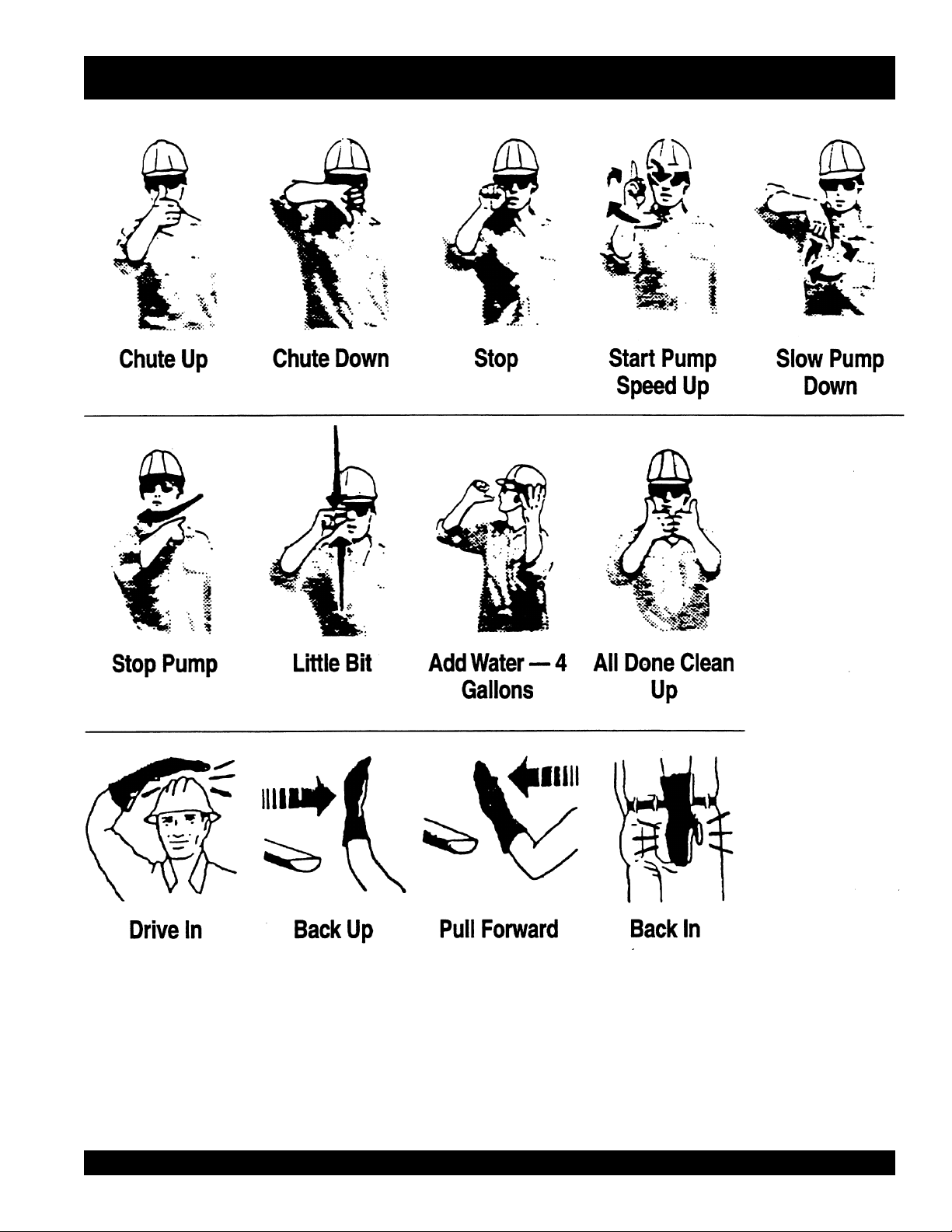
IMPORTANT HAND SIGNALS
C-30HD — PARTS & OPERATION MANUAL — REV. #4 (03/06/01) — PAGE 9
Page 10

GENERAL INFORMATION
The following operating principles and operating suggestions
should prove helpful in the successful operation of your
concrete pump. Your new “small line” concrete pump has been
designed to give you many years of service when operated
properly. A study of the following paragraphs is important to
the successful operation of your new Direct-flo Concrete
Placer.
All concrete pumps require a high level of operator skill and
more frequent service than most of the other construction
equipment. The highly abrasive nature of concrete under
pressure makes it extremely important that expendable wear
components be inspected at regular intervals between jobs
to prevent having to replace these items during a pour.
Experience has proved that inconsistency of batched concrete
mixes and frequent moving of the line requires the operator to
be readily available at all times during pumping to stop the
pump and prevent abuse to the unit which may occur if
unexpected blockages develop.
PUMP MIX GUIDELINES
When ordering concrete, be certain to advise the concrete
supplier that you require a “pump mix”. The Direct-flo manifold
will pump a wide variety of materials, but certain basic
principles must be followed to assure successful pumping, as
follows:
1. Generally speaking, the washed concrete sand and #4
aggregate (pea gravel) should conform to A.S.T.M. standards
in regard to sieve analysis. Sands in some areas are washed
clean of the #100 and #200 mesh fines, which results in
separation and jamming in the manifold while pumping under
pressure. If this condition develops, check with your concrete
suppliers engineers and get their recommendations for
supplementing the lack of the fines. The use of locally accepted
ad-mixs may be required. (For example, Pozzolith, Bentonite
Clay, Plastiments, etc.) When properly prescribed, additives
form the plastic paste sometimes necessary to hold the
cement and aggregate together. NOTE: If jamming conditions
in the pump or hose occur for any reason at all, do not attempt
to use more power to correct the condition. Determine the
cause of jamming, correct it and resume pumping. Trying to
force material through under jammed conditions may result in
damage to the drive system, thus voiding any warranty
services.
2. As a general rule, the use of approximately six sacks of
cement, 70% washed concrete sand and 30% #4 pea gravel
per yard of concrete will result in a pumpable mix. The ideal
nature of sand and rock in certain areas may permit you to
increase the percentage of rock or adjust the mix considerably
to meet the job requirements. When possible, you may
experiment with various mixes in your area to determine the
degree of versatility of the Direct-flo Pump.
3. Uniform gradition of the washed concrete sand and the 1/2”
minus aggregate along with sufficient cement content and
water are important to a successful pump operation.
4. A recommended pumpable mix design would be 70% sand
and 30% aggregate-cement content to be a minimum of 6
sacks. (564 lbs.)
NOTE; Your local sand and rock engineers will give you the
s.s.d. weights of sand and rock required in your local area
which will yield one cubic yard per the above recommendation.
SAMPLE DESIGN MIX
6 1/2 sacks cement (611 lbs.)
1800 lbs. washed concrete sand
1000 lbs. pea gravel
230 lbs. water
5. Test laboratory data has proven in many areas that the
above mix guidelines have produced concrete rated at 3000
psi (28 day test) and upwards of 5000 psi with an increase in
cement.
6. In some areas where the gradation of sand and rock is
ideal and sufficient cement is used along with admixtures, the
Mayco small line concrete pump will handle up to a 50-50
ratio of sand and rock.
7. When the mix is designed for wet gunning applications, it is
normal to increase the cement (up to 7.5 or 8 sacks) and
change the sand to rock ratio to 85% sand and 15% rock.
8. The Mayco concrete pump will valve efficiently when using
cellular-foam concrete mixes upwards of 70 lbs. per cubic foot
wet density. (Below 70 lbs. materials (roof decks) the valving
becomes inefficient.)
PAGE 10 — C-30HD — PARTS & OPERATION MANUAL — REV. #4 (03/06/01)
Page 11

NOTE PAGE
C-30HD — PARTS & OPERATION MANUAL — REV. #4 (03/06/01) — PAGE 11
Page 12

C-30HD — HOW IT WORKS
The Mayco concrete pump has one main pumping piston
which is valved by means of two ball checks. (A inlet, and B
outlet.)
The secondary piston is used as a compensator piston to
smooth out the pulsations of a single piston action. Note: The
compensator will not start operating until material is pumped
into the line and back pressure develops.
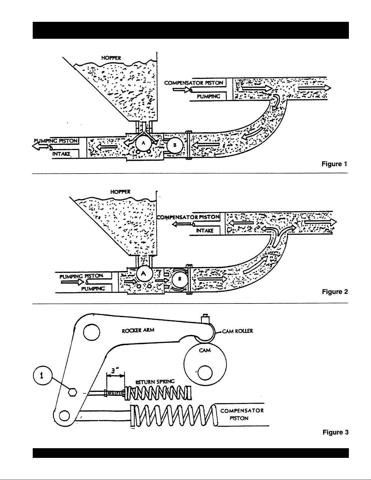
The compensator spring, which is installed on the
compensator piston rod, deflects with each piston stroke. This
“spring cushion”, in conjunction with the cam profile, produces
and uninterrupted smooth flow of material under average
pumping conditions.
An automatic, centrifugal clutch is installed to engage and
disengage the pumping action without stopping or starting the
engine. The centrifugal clutch is set at 1100 R.P.M. release.
The engine idle speed is approximately 750 R.P.M.; therefore,
the clutch is completely disengaged at idle. The throttle settings
while pumping should always maintain an engine R.P.M. high
enough to prevent the clutch from slipping and burning the
clutch lining.
The return spring which is installed on the rocker arm, is
installed to eliminate shock and stress between the cam roller
and the cam weldment when the pump is in operation. If the
return spring is removed or replaced for any reason, maintain
the backing plate dimension of 3” as shown on Figure 3, to
produce the proper pre-loading of the spring for a smooth
performance.
Figure 1- The pumping cylinder retracts drawing the material
past the ball (A) and filling the cylinder. The compensator piston
is pumping the material out to the nozzle and causing ball (B)
to seat preventing the material from returning to the pumping
cylinder intake.
Figure 2- The pumping piston is forcing the material past ball
(B) and out to the nozzle, also seating ball A so that the material
will not flow back to the hopper. This action also fills the
compensating piston for the next stroke.
Figure 3- Shows the relationship between the return spring,
the compensator spring and the rocker arm to maintain a
smooth performance. Do not tighten the bolt (Item 1)
completely, the rod end must be able to move.
PAGE 12 — C-30HD — PARTS & OPERATION MANUAL — REV. #4 (03/06/01)
Page 13
C-30HD — HOW IT WORKS
C-30HD — PARTS & OPERATION MANUAL — REV. #4 (03/06/01) — PAGE 13
Page 14
C-30HD OPERATING INFORMATION
OPERATING SUGGESTIONS
1. A well-planned location of the pump and routing of the hose
before starting a pour may save subsequent moves
throughout the job.
2. Before concrete is discharged into the hopper, it is
suggested that 3 to 4 gallons of water be sprayed into the
hopper, followed by approximately 5 gallons of a creamy
cement and water slurry (1/2 bag of cement to 5 gallons of
water). This procedure lubricates the hose and prevents
separation and blockages in the hose. Note: Getting the
concrete to flow through the hose at the start of the pumping
cycle can be one of the most critical operations of the pour.
(Manually operate the throttle - when starting. NOT
REMOTELY)
3. It is important that once the slurry procedure is completed,
and you have started concrete flowing through the hose, do
not stop the pour until all the slurry is pumped out and the
concrete has reached the end of the hose. The only time to
stop the pump at the start is if a blockage occurs.
4. When the pump is stopped for any reason during a pour;
e.g., moving hose, waiting for redi-mix truck, the following
suggestions are offered:
A. Leave the hopper full of concrete at the time of shutdown. It
is important not to let the redi-mix driver wash too much water
into the hopper, as this could cause separation of the
concrete in the hopper.
B. If the shutdown period exceeds 2 to 3 minutes, turn off the
engine so the vibration does not separate the mix in the hopper
which can cause a blockage in the manifold when the pump
is started.
C. If it is necessary to wait 10 minutes or more for another load
of concrete, it is wise to start the pump and pump 6 or 8 strokes
every 5 minutes to prevent setting of the mix in the system. If
waiting time is excessive, it would be wise to wash out the
pump and hoses and start over when the new truck arrives.
D. When pumping stiff mixes and there is waiting time between
redi-mix trucks, it is advisable to add some water to the last
hopper of material and “hand mix” to ensure an easier start
with the following load.
E. When the pumping job requires a stiffer mix, the following
method is suggested for starting: Take a water hose with a
nozzle on it and apply water with a fine spray to the concrete
as it comes down the redi-mix chute into the pump hopper
after the slurry procedure is completed and you are ready to
start pumping. Using this procedure will make it easier to pump
through the clean hose. Note: Once the concrete has reached
the end of the hose, do not apply any more water in this manner
as this procedure is used on the start only.
F. Hose sizing is very important: We strongly recommend on
harsh mixes, vertical pushes, stiff concrete, shotcrete, long
pushes, that a 2 1/2” line be used as far as possible. The
advantages of using the 2 1/2” line are improved pumpability,
less pumping pressure and less wear on the pump.
5. Following the pump operation, proper wash out of all
materials or “build-up” within the pump manifold and hoses
will prevent problems when starting the next job.
6. A thorough inspection of the drive components and greasing
of all bearings after each job will ensure adequate lubrication
and service to the pump which is normally operating in wet,
gritty conditions. Note: Over-greasing any bearing on your
Mayco pump will not damage the bearing.
your pump to push through blockages due to separation of
material in the hose or manifold, you will soon have
breakdowns and costly repairs which are not covered under
warranty. If a blockage occurs, find where it is and clear it before
further pumping. Do not use horse-power; it will only make it
worse.
hopper of concrete can cause severe damage or breakage
of the axle and axle springs, excess strain and pressure on
the hub and bearing assembly.
7. Warning: Common sense tells us that if
you drive a truck into a brick wall, something
is going to be damaged. The same holds true
with your concrete pump. If you repeatedly
pull the throttle all the way out and try to force
8. Warning: It will be necessary at times to
move your pump from one job site location
to another. Before moving the pump, make
sure to pump the remaining concrete out of
the hopper. Moving the pump with a full
PAGE 14 — C-30HD — PARTS & OPERATION MANUAL — REV. #4 (03/06/01)
Page 15

C-30HD OPERATING INFORMATION
PUMPING TIPS AND TROUBLE SHOOTING
1. The effects of heat and excessive time on concrete: Hot
concrete, commonly referred to as a hot load, is concrete that
has been in the redi-mix truck in excess of 2 to 3 hours. On a hot
day, this amount of time is even less. A brief explanation of why
heat and time affect concrete: Concrete starts setting by drying
up through a chemical reaction. The catalyst to this reaction is
heat. When pumping a hot load, it is important to remember that
when you have to stop pumping for any reason, add water to
the concrete in the hopper and hand mix and move concrete in
the hose every 5 minutes. If the shut down time becomes too
long, wash out immediately.
2. ADMIXTURES: A remixtures that are designed into the
concrete mix by the redi-mix company or an architectural
engineering company. This section lists common admixtures
and a brief explanation of their function.
A. POZZOLITH 300 R or the equivalent acts as a water
retarder and a lubricant. On a lean mix, long pushes, stiff
mixes, and vertical pushes, Pozzolith 300 R helps
pumpability.
B. MBVR, air entraining, acts as a lubricant.
5. Damaged hoses with internal restrictions can cause
blockages.
6. If a blockage occurs in a hose, “walk the hose” until you find
the point of trouble. The hose will be soft immediately past the
blockage. If this happens at the start, disconnect the hose at
the first coupling past the blockage. Elevate the hose at that
point with the blockage area hanging down.
extreme care! The hose line is under pressure and can
cause serious injury.
down-stream edge of the packed area until it is free to flow.
Shake all of the sand and gravel out to the end of the hose.
Before reconnecting the hose, start the pump and run a small
amount of concrete out to the end of the hose. This will assure
that all of the separation is out of the hose.
7. The manifold is plugged if the volume at the discharge end
of the hose stops, and the hose is soft. The drive belts will
start to slip and the engine will lugdown.
To clear a plugged manifold,
dangerous condition will exist due to pressure build-up inside
the manifold.
Follow these instructions carefully:
Note: Use
Using a hammer, you can pound the
great care must be taken as a
C. CALCIUM CHLORIDE, commonly referred to as C.C., is
used as an accelerator. When pumping a load with calcium
chloride, it is recommended that you wash out if the waiting
time between delivery trucks becomes too long.
D. SUPER PLASTICIZERS, acts as an accelerator. The
concrete will look very wet after the super plasticizer is
added, but will begin to set up very fast. Wash out
immediately if you do not have a truck waiting. Super
plasticizers are used mainly on commercial jobs.
E. RED LABEL, acts as a water retarder and an accelerator.
Red label will be used mainly on commercial jobs.
F. FLY ASH, is used to help increase the strength of the
concrete and decrease the cement content per yard. This
is one of the most common admixtures used.
NOTE: All admixtures will be shown on the redi-mix concrete
ticket. Before starting the pumping job, ask the driver of the
redi-mix truck to see the concrete ticket and note the
admixtures that exist and take the proper action.
3. When pumping long distance or pumping stiff mixes, you
can expect a drop in volume compared to shorter lines and
wetter mixes due to the change in valve efficiency or cavitation.
4. Leaking manifold seals or hose coupling gaskets which leak
water can cause separation and subsequent jamming at that
point.
7.1 Stop the pump. Switch off the engine.
7.2 DO NOT open any of the delivery system joint clamps.
7.3 The senior experienced operator must warn all others to
stand at least 20 feet away from the machine and turn their
heads away from the manifold.
7.4 The operator must position himself/herself away from the
hinged side of the manifold.
7.5 Wearing safety glasses, grasp the clamp arm weldment
and carefully pull it open to the primary (safety) position. STOP
count to 20. This will allow the pressure to release.
7.6 After the pressure has been released, open the clamp
arm weldment and swing the hinged discharge cone open.
7.7 Remove blockage with around a 2-foot length of reinforcing
steel rod. Flush the manifolds with water. Make sure the (3” x
2”) reducer is clear of any blockage before closing the
discharge cone.
7.8 After the blockage has been cleared and the pump
manifold has been thoroughly flushed with water, close the
hinged discharged cone and lock into place.
7.9 Before reconnecting hose to the reducer, start the engine
and pump two or three shovels of concrete through the
reducer. This will insure that all the blockage has been cleared.
C-30HD — PARTS & OPERATION MANUAL — REV. #4 (03/06/01) — PAGE 15
Page 16

C-30HD OPERATING INFORMATION
7.10 Shake out around 2 feet of concrete before reconnecting
hose to pump. After this is done, connect hose to pump and
resume the pumping operation.
8. If it is necessary to wait 1/2 hour or more for another load of
concrete, it is advisable to consider the factors affecting the
concrete that is already in the pump and system. To prevent
setting of the mix in the system: 1) how old is the concrete ? 2)
is there an accelerator, calcium chloride, red label, etc., in the
concrete ? 3) the temperature of the day, 80, 90, degrees? 4)
how much system you have out and how stiff was the mix you
were pumping? If, for any reason, the mix should set up in the
system, the following procedure is suggested:
Note: Use extreme care! The hose is under pressure!
Disconnect the hose from the pump and wash the pump out
immediately. Reconnect the hose and fill the hopper with water.
DO NOT try to push all the concrete out of all of the hose line
at one time. For example: If you had 200 ft. of system out, you
would disconnect each hose. Clean it out by pushing water
through the first hose off the pump, then continue progressing
through all the hoses, until all the system is clean. If waiting
time is excessive, it would be wise to wash out the pump and
hoses and start over when the new truck arrives. This can be
avoided by being attentative to the pump and system, also
taking into consideration the above 4 factors affecting the mix.
9. “Down-hill pumping” can be difficult on some jobs. The slurry
procedure would be the same as explained on the pages titled
Operating Suggestions. It is suggested that a sponge 2”x 4”x
6” be placed in the hose before the start of pumping. Wet the
sponge before placing it in the hose. The reason for using the
wet sponge is to keep the slurry from running too far ahead of
the concrete and so reducing the possibility of separation.
When the pump is stopped, the material can flow slowly down,
due to gravity, and cause the hose to collapse. When pumping
is resumed, you can expect a blockage at the point of hose
collapse. To prevent this from happening, the hose can be
“kinked off” at the discharge end when the pump is stopped
to prevent the gravity flow of the material in the hose. The use
of stiffer mixes when pumping down-hill will decrease gravity
flow of the material in the hose and will assure a smoother
operation between the cam roller bearing and cam plate. As
with any job, make sure that the hose and the couplings are in
good workable shape.
10. When pumping vertically:
A. When pumping vertically up the side of a building, above
40 feet, we would recommend the installation of steel pipe
securely fastened at intervals as necessary to support the
pipe. Ninety degree, long radius pipe sweeps should be
installed at the top and bottom of the steel line. Use a 25 ft.
hose, or short section, off the pump; and for the balance of
the horizontal distance to the vertical line, use steal pipe. This
type of installation has been satisfactory on many jobs being
pumped in excess of 100 feet high. Line pressures are always
less using steel pipe as compared to hose.
B. When pumping vertically, using all hose, it is recommended
not to go higher than 50 feet with hose. The hose should be
tied off at intervals of 10 feet, if possible. Special attention
should be given when tieing the hose off at the top as the
hose will have a tendency to stretch when filled with concrete.
This will increase the possibility of a blockage at the point where
the hose is tied off. To avoid this, a long radius of 90 degree
elbow is recommended. The suggested place to tie off is on
the hose, under the clamp.
that pipe be used on all vertical pumping for safety and
convenience.
If it is absolutely necessary to use hose, then use this section
as a guide.
11. If the volume at the end of hose starts to decrease gradually
and eventually almost stops, it is quite likely that the valve
seats have had excessive wear and need replacement. Once
they have reached a certain wear point, they may “channel
out” rapidly and material will reciprocate past the ball on each
stroke. The hollow steel ball should be replaced when it starts
to show dents or appears to be badly worn. Sand and
aggregate materials in some areas are extremely sharp and
hard and therefore highly abrasive. Under these conditions
when pumping stiff mixes, or to high elevations which cause
line pressures, it will be noted that valve components may
have short wear life. If this condition exists, it is advisable to
remove the manifold only, and inspect the lower seat at the
end of each day. If it appears that the seat is beginning to
“channel out, replace before starting the next day’s pour. The
upper valve seat can be inspected after each washout by
running your finger around lower edge of seat where the ball
makes contact. You can reach this from the inside of the hopper.
Be sure that the engine is turned off.
Note: It is strongly recommended
PAGE 16 — C-30HD — PARTS & OPERATION MANUAL — REV. #4 (03/06/01)
Page 17

C-30HD OPERATING INFORMATION
12. Slight pulsation of the hose will always be noticeable near
the pump. Excessive pulsation of the hose near the pump is
normally due to higher than average line pressures caused
by stiff, harsh mixes, or extremely long pumping distances.
The use of 2 1/2” I.D. hose in these extreme cases reduces
line pressures or the addition of slight amounts of water to the
mix, if permissible, will permit easier pumping. The use of
certain pumping admixtures may help.
If excessive pulsation exists in the hose, it is advisable to use
burlap or some means of wear protection under the hose at
points where the hose may wear through the outer cover; e.g.
over forms, steel or sharp curbs.
13. If the cam roller does not ride on the cam profile smoothly,
it may be caused by insufficient line back-pressure; e.g., a
wet mix with only 50 feet of hose. Add more hose as necessary.
It can also be caused by cavitation or the passing of oversized aggregates through the valving, causing it to skip.
14. When using Snap-Joint couplings with gaskets to join hose,
see that they are washed clean after each job. Keeping the
hose ends clean (heavy duty) is very important for the best
job setup. A thin coat of grease on the rubber gasket or dipping
both coupling and gasket in water before coupling the hose
will make for easier installation.
15. All new pumps are “water pressure tested” at the factory
before shipment. This procedure permits a thorough inspection
of entire drive system and valving under simulated full load
conditions. The pump owner can do the same by attaching
an adaptor to couple to the end of the discharge cone; e.g.,
the use of a standard 2” pipe cap with a 3/8” hole drilled in the
center , screwed on to the end of the hinged cone or reducer
at the pump. Fill the hopper with water after making sure that
all sand and rock have been removed from the manifold.
Operate the pump at full throttle and the 3/8” diameter hole
restriction will create sufficient back-pressure to make a
thorough inspection of all moving parts.
CLEAN UP PROCEDURE
PART A
1. Ensure that there is no blockage in the hose and line (See
Page 15, Para. 6) or in the manifold (See Page 15, Para. 7). If a
blockage exists, clear it as it dictates how the machine will
pump the next time it is used. At the end of every pour, or
because of long delays during a pour, the pump and delivery
system must be thoroughly cleaned by removing all concrete
material.
2. Proper wash out of all materials or build up within the pump
manifold and hoses following the pumping operation will
prevent problems when starting the next job. After completion
of the pour, pump the remaining concrete in the hopper
through the discharge line.
3. Note: To avoid the possibility of separation during clean-up,
do not pump the concrete below the inlet ball in the hopper. It
is best to leave approximately 3 to 4 inches of concrete above
the inlet ball.
4. Turn the pump engine off before filling the hopper with water.
Engine vibration at idle may “separate” material in the hopper,
causing jamming in manifold when pumping is resumed.
5. Fill hopper with water and resume pumping. The water will
push the concrete through the line. When the water runs clear
at the end of the hose, disconnect lines and shake out all the
sand and sediment so the lines will be clean for the next pour.
6. It is important that the hinged discharge cone on the pump
manifold be opened and all remaining concrete (rock and
sand) be thoroughly washed out. This must be done after each
job to prevent concrete build up in the discharge manifolds
and 3” discharge elbow.
16. Before starting the pumping operation, the following check
list procedure should be followed:
1. Check the engine oil.
2. Check the oil reservoir of the lubrication system to make
sure that it is full.
3. Inspect the chain and belt adjustment.
4. Check the cam oiler.
5. Start and run the engine a minimum of five minutes before
starting the pumping operation.
Note: When the redi-mix truck arrives, it is always a good idea
to check the concrete ticket and make sure you have the
proper mix design.
C-30HD — PARTS & OPERATION MANUAL — REV. #4 (03/06/01) — PAGE 17
Page 18

C-30HD OPERATING INFORMATION
PART B
This section will explain the recommended procedure for using
a sponge to clean out the lines. After completion of the pour,
pump the remaining concrete in the hopper through the
discharge line. Using a shovel, clean the sides of the hopper.
(Note: The pump engine should be turned off, as explained in
Part A of the Clean Up Procedure.) After the sides of the hopper
have been cleaned, add a small amount of water to the
remaining concrete in the hopper and hand mix.
Start the pump engine and pump the hopper all the way down.
Disconnect the hose from the pump. Fill the hopper with water
and pump the remaining concrete out of the pump. Open the
hinged discharge cone and thoroughly wash out all remaining
concrete (sand-sediment) from the cone and pump manifolds.
Close the discharge cone and lock in place. Take a sponge
(2”x 4”x 6”) and soak it with water. Take the hose that is
disconnected from the pump and shake out the concrete so
that about 2 feet of it is clear. Insert the sponge into the hose.
Reconnect the hose to the pump. Fill the hopper with water
and resume pumping. Run the pump approximately half
throttle. The sponge will be discharged at the end of the line
followed by clear water. At this point, the pump and lines will
be completely clean and ready for the next job.
WARNINGS
1. Never put your hands, or any other parts
of your body, in the hopper when the engine
is running.
2. Never use muriatic acid to clear the pump.
Acid will dissolve the chrome finish on the
pumping cylinder.
3. When using a clean-out hook to clean out back into the
redi-mix truck, use a safety chain to secure the clean-out hook
to some solid part of the redi-mix truck to prevent the hook
from jumping off the redi-mix truck’s hopper. Run the pump at
half throttle.
4. Never use air to clean out the lines.
Always think safety first!
PAGE 18 — C-30HD — PARTS & OPERATION MANUAL — REV. #4 (03/06/01)
Page 19

CONCRETE MIX INFORMATION
CONCRETE MIX DESIGNS-SCREEN ANALYSISTERMINOLOGY
The following information has been prepared to assist in the
selection of concrete mix designs in certain areas where the
use of concrete pumps is a new industry.
The result of years of experience by many concrete pump
users and aggregate suppliers has proven the importance of
certain requirements necessary to successful concrete
pumping. The strength and quality of the concrete is relative
to the cement/water ratio and the type of gradation of the
aggregates used.
Special emphasis is given to the gradation of the fine
aggregates, coarse aggregates sand and used in all pump
mixes. Generally speaking, if the screen analysis of the local
sand and rock conform to the A.S.T.M. specifications shown
on Pages and 13 and the proper ratio of sand and rock are
used in the mix, you can expect a pumpable mix.
If difficulty is experienced in pumping the mixes shown on
Pages 11 and 12, consult your local aggregate supplier with
this information and make the necessary adjustments.
DEFINITIONS
ONE SACK CEMENT (U.S.)-94lbs. (42.58 KG)
S.S.D.-Saturated Surface Dry: Meaning sand particles may
be saturated with moisture but there is no free water on the
surface.
OVEN DRY-meaning all the moisture is removed from the sand
particle.
SLUMP-a measure of moisture consistency.
W/C SAND-washed concrete sand.
#4 GRAVEL or ROCK-3/8” PEA GRAVEL (1/2” MINUS)
#3 GRAVEL or ROCK-3/4” rock (1” minus)
POZZOLITH-Master Builders Admixture -(Pozz)
P.S.I.-compressive strength (Pounds per Square Inch)
DEFICIENCIES IN SIEVE ANALYSIS of AGGREGATES
The uniform gradation of sand and aggregate in the concrete
mix is extremely important in all pumping operations. It is highly
possible that the lack of certain sieve sizes may prevent
pumpability. In some areas it may be necessary to make up
these deficiencies by the addition of “blending sands” to the
local sand.
GENERAL RULE-supplement to improve pumpability.
FLY ASH-use up to 15% of cement weight.
POZZOLIN-use up to 13% of cement weight.
C-30HD — PARTS & OPERATION MANUAL — REV. #4 (03/06/01) — PAGE 19
Page 20

CONCRETE MIX INFORMATION
The following information has been extracted from actual testing laboratory reports. The purpose of this printing is only to help
create a better understanding of the importance of uniform gradation and proportioning of materials which affect pumpability of
concrete mixes. These weights and proportions illustrate that when the sieve analysis is ideal, the sand/rock ratio can be adjusted
(65% sand 35% rock) and pumpability should be excellent.
EXAMPLE #1 (A California Test Lab. Report)
JOB: Building Foundations (Water Project)
Sacks per cu./yd. 6.5 designed for 2,500 lbs. in 28 days
Gallons per sack 7.1
Washed Sand-#200 wash 1.3
Organic matter-OK
Specific gravity (SSD) Sand-2.58; Pea Gravel-2.60
Sieve analysis-percent passing
Material 1.5” 1” 3/4” 3/8” #4 #8 #16 #30 #50 #100 #200
W.C. Sand 100 99.7 79.1 60.4 36.5 14.3 4.0 1.1
Pea Gravel 100 3.0
% Comb. 100 66 51 39 23 9 3 1.0
DESIGN FOR ONE YARD OF CONCRETE (SATURATED & SURFACE DRY):
Absolute volume of aggregate in one cu. yard: 17.78 cu. ft.
Specific gravity of aggregates in one cu. yard: 2.58
Weight of aggregates in one cu. yard batch: 2850 lbs.
% BATCH SPEC. GRAVITY ABS. VOL.
W.C. Sand 65 1800 2.58 11.56
PEA GRAVEL 35 1000 2.60 6.22
WATER 46 gal. 1
CEMENT 6.5 sk. 611
TOTAL 27.00
ADMIXTURE: None
SLUMP 4”
REMARKS This mix designed for pumping
NOTE: Due to the availability of well-graded sand as shown in the above sieve analysis,
this mix pumped very successfully.
PAGE 20 — C-30HD — PARTS & OPERATION MANUAL — REV. #4 (03/06/01)
Page 21
A.S.T.M. STANDARD SPECIFICATION FOR GRADING AGGREGATE
Screen Size of Operating Percentage Passing
U.S. Metric (by weight)
FINE AGGREGATE: Referred to as washed concrete sand.
3/8” 3/8” 9.51mm 100%
#4 4760 micron 4.76 mm 95 to 100%
#8 2380 micron 2.38 mm 80 to 100%
#16 1190 micron 1.19 mm 50 to 85%
#30 590 micron 1.19 mm 50 to 85%
#50 297 micron 297 µ 10 to 30%
#100 149 micron 149 µ 2 to 10%
3/8” (9.51 mm) PEA GRAVEL AGGREGATE: Referenced to as #4 Rock or Gravel or 1/2” minus (12.7 mm) size.
1/2” 1/2” 12.7 mm 100%
3/8” 3/8” 9.51 mm 85 to 100%
#4 4760 micron 4.76 mm 10 to 30%
#8 2380 micron 2.38 mm 0 to 10%
#16 1190 micron 1.19 mm 0 to 5%
C-30HD — PARTS & OPERATION MANUAL — REV. #4 (03/06/01) — PAGE 21
Page 22

CONCRETE MIX INFORMATION
Consolidated Rock Products Co., Division of Tests
3/8” Pea Gravel STANDARD PUMP MIXES (one-half inch minus)
NOTE: All weights shown are one cubic yard with S.S.D. aggregates.
CRP Mix Number 6004 .......................... 6005 .............................6006 .......................... 6007
Design Slump (in.) 6” (15 cm) ............. 6” (15 cm) .................6” (15 cm) ............. 6” (15 cm)
Cement, SACK. 7.0 ................................ 7.0 ......................................7.0 ................................ 7.0
Cement, Lbs. 658 (298 kg) ............ 658 (298 kg) ................658 (298 kg) ............ 658 (298 kg)
w/Con Sand (1 lb.) 2031 (920 kg) ............ 2982 (943 kg) ................1879 (851 kg) ............ 1943 (880 kg)
Gravel #4(9.51 mm) 677 (307 kg) ............ 693 (314 kg) ................806 (365 kg) ............ 832 (377 kg)
TOTAL AGGREGATE 2708 (1227 kg) .......... 2775 (1257 kg) .............2685 (1216 kg) .......... 2775 (1257 kg)
ADMIXTURE
Pozzolight 311-1 lb. 1.4 (.63 kg) ............. 1.4 (.63 kg) ................. 1.4 (.63 kg) ............. —
Water, Design (gals.) 50.0 (189 liters) ......... 53.0 (200 liters) ............50.0 (189 liters) ......... 53.9 (200 liters)
Mater, Max. (gals.) 50.0 (189 liters) ......... 53.0 (200 liters) ............53.0 (200 liters) ......... 53.0 (200 liters)
NOTE: Multiply above kilograms and liters by 1.308 to obtain the proportions for one cubic meter of concrete.
Consolidated Rock Products Co., Division of Tests
3/8” Pea Gravel STANDARD PUMP MIXES (one-half inch minus)
NOTE: All weights shown are one cubic yard with S.S.D. aggregates.
CRP Mix Number 6000 .......................... 6001 .............................6002 .......................... 6003
Design Slump (in.) 6” (15 cm) ............. 6” (15 cm) .................6” (15 cm) ............. 6” (15 cm)
Cement, SACK. 6.5 ................................ 6.5 ......................................6.5 ................................ 6.5
Cement. Lbs. 611 (276 kg) ........... 611 (276 kg) ................ 611 (276 kg) ............ 611 (276 kg)
w/Con Sand (1.1 lb.) 2062 (934 kg) ........... 2112 (957 kg) ................1924 (872 kg) ............ 1971 (893 kg)
Gravel #4 (9.51mm) 687 (311 kg) ........... 704 (319 kg) ................ 825 (374 kg) ............ 845 (383 kg)
TOTAL AGGREGATE 2749 (1245 kg) .......... 2816 (1276 kg) .............2749 (1245 kg) .......... 2816 (1276 kg)
ADMIXTURE
Pozzolight 311-1.3lb. 1.3 (.59 kg) ............. 1.3 (.59) ......................—
Water, Design (gals.) 50.0 (189 liters) ......... 53.0 (200 liters) ............50.0 (189 liters) ......... 53.9 (200 liters)
Mater, Max. (gals.) 50.0 (189 liters) ......... 53.0 (200 liters) ............53.0 (200 liters) ......... 53.0 (200 liters)
NOTE: Multiply above kilograms and liters by 1.308 to obtain the proportions for one cubic meter of concrete.
PAGE 22 — C-30HD — PARTS & OPERATION MANUAL — REV. #4 (03/06/01)
Page 23
1. To obtain a representative sample, take samples at three or
more regular intervals throughout the discharge of the mixer
or truck. DO NOT take samples at the beginning or end of the
discharge.
2. Dampen the inside of the cone and place it on a smooth,
moist, nonabsorbent, level surface large enough to
accommodate both the slumped concrete and the slump cone.
Stand on the “foot pieces” throughout the test procedure to
hold the cone firmly in place.
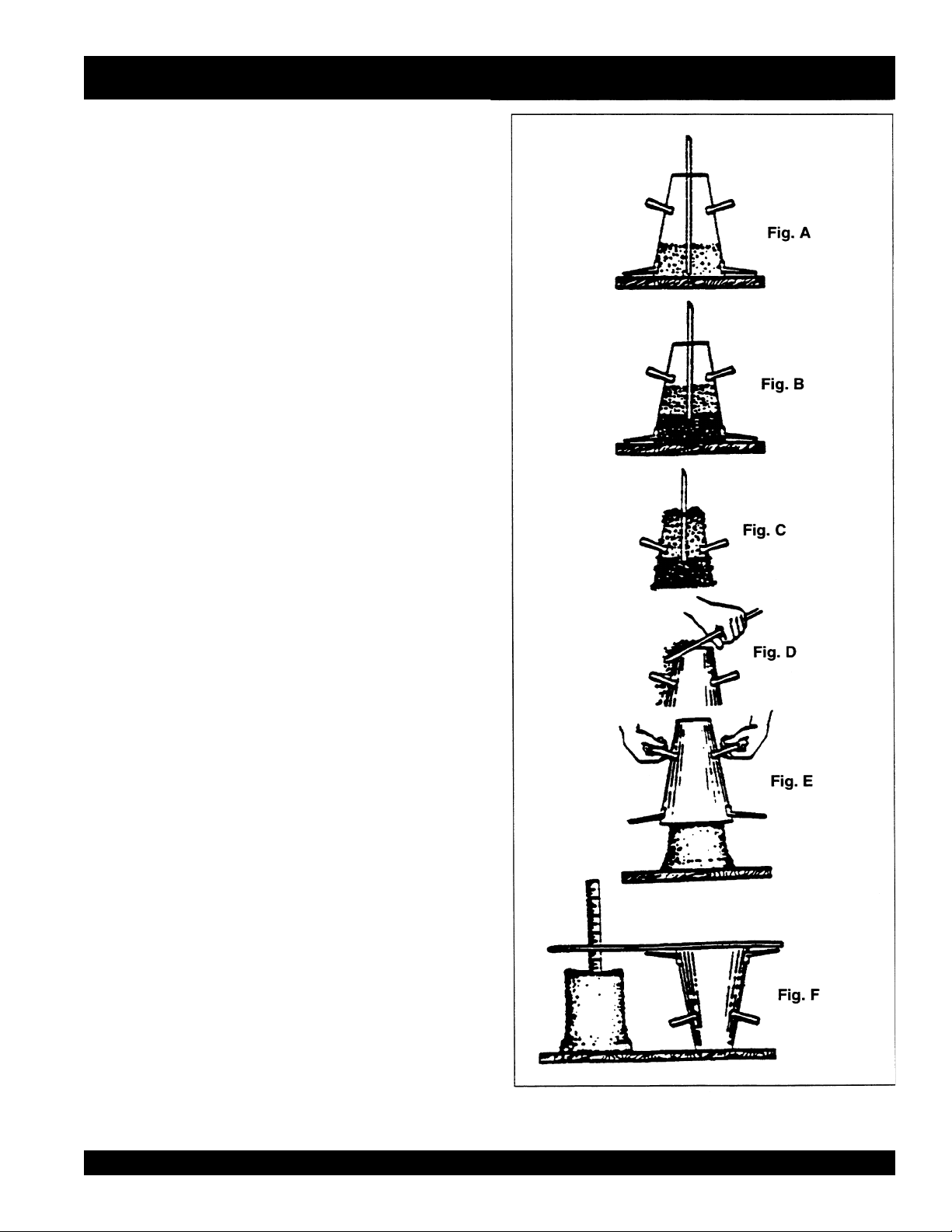
3. Fill the cone 1/3 full by volume and rod 25 times with a 1/2”
dia x 24” lg. bullet-pointed steel rod. (This is a specific
requirement which will produce non-standard results unless
followed exactly.) Distribute rodding evenly over the entire cross
section of the sample. (See figure A.)
4. Fill cone another 1/3 which will make the cone 2/3 full by
volume. Rod this second layer 25 times with the rod penetrating
into, but not through, the first layer. Distribute rodding evenly
over the entire cross section of the layer. (See figure B.)
5. Fill cone to overflowing. Rod this layer 25 times with rod
penetrating into but not through, the second layer. Distribute
rodding evenly over the entire cross section of this layer. (See
figure C.)
SLUMP TEST PROCEDURE
6. Remove the excess concrete from the top of the cone, using
the tamping rod as a screed. (See figure D.)
7. Lift the cone vertically with a slow even motion. Do not jar
the concrete or tilt the cone during this process. (See figure
E.) Invert the withdrawn cone, and place it next to, but not
touching the slumped concrete.
8. Lay a straight edge across the top of the slumped cone.
Measure the amount of slump in inches from the bottom of
the straight edge to the top of the slumped concrete at a point
over the original center of the base (See Figure F). The slump
operation must be complete in a maximum elapsed time of 11/2 minutes. Discard the concrete. DO NOT use it in any other
tests.
C-30HD — PARTS & OPERATION MANUAL — REV. #4 (03/06/01) — PAGE 23
Page 24

EXPLANATION OF CODE IN REMARKS COLUMN
How to read the marks and remarks used in this parts
book.
Items Found In the “Remarks” Column
Serial Numbers-Where indicated, this indicates a serial
number range (inclusive) where a particular part is used.
Model Number-Where indicated, this shows that the
corresponding part is utilized only with this specific model
number or model number variant.
Items Found In the “Items Number” Column
All parts with same symbol in the number column,
■
, belong to the same assembly or kit
If more than one of the same reference number is
listed, the last one listed indicates newest (or latest)
part available.
*
, #, +, %, or
NOTE
NOTE
The contents of this catalog are
subject to change without notice
.
PAGE 24 — C-30HD — PARTS & OPERATION MANUAL — REV. #4 (03/06/01)
Page 25

C-30HD SUGGESTED SPARE PARTS
C-30HD Concrete Pump
1 Units
Qty. P/N Description
6 ...... EM14904 ..................... PISTON CUP KITS
4 ...... EM18804 ..................... 4 1/2" STEEL BALL
4 ...... EM14818 ..................... 4" STEEL BALL
6 ...... EM14903 ..................... BALL STOP PIN KIT
10 ...... EM18801 ..................... 0-RING MANIFOLD
1 ...... EM14308 ..................... CHAIN
2 ...... EM26313 ..................... HALF LINK
2 ...... EM26314 ..................... MASTER LINK
1 ...... EM14334 ..................... COMPENSATOR SPRING
2 ...... EM14408 ..................... BRONZE RING
2 ...... EM903092 ................... CAM ROLLER BEARING
2 ...... EM14315 ..................... V-BELT
2 ...... EM14842 ..................... LOWER SEAT
2 ...... EM14843 ..................... UPPER SEAT
2 ...... EM26310 ..................... CLUTCH LINING
10 ...... EM18409 ..................... O-RING
2 ...... EM20763 ..................... FUEL FILTER
2 ...... EM26746 ..................... OIL FILTER
2 ...... EM20328TKIT ............. BEARING KIT
1 ...... EM28004DD ................ REDUCER 3" X 2"
1 ...... EM23946 ..................... 3" ELBOW
2 ...... EM28904 ..................... 3" CLAMP
4 ...... EM28904-1 .................. 3" GASKETS
1 ...... EM14159 ..................... HOPPER SCREEN
1 ...... EM14401 ..................... OIL PUMP
1 ...... EM20709 ..................... SOLENOID
2 ...... EM2074........................ THROTTLE LINKAGE
NOTE
Part number on this Suggested
Spare Parts List may super cede/
replace the P/N shown in the text
pages of this book.
C-30HD Concrete Pump
3 Units
Qty. P/N Description
10 ...... EM14904 ..................... PISTON CUP KITS
10 ...... EM18804 ..................... 4 1/2" STEEL
10 ...... EM14818 ..................... 4" STEEL BALL
12 ...... EM14903 ..................... BALL STOP PIN KITS
25 ...... EM18801 ..................... MANIFOLD O-RINGS
3 ...... EM14308 ..................... CHAINS
10 ...... EM26313 ..................... HALF LINK
10 ...... EM26314 ..................... MASTER LINK
2 ...... EM14334 ..................... COMPENSATOR SPRING
4 ...... EM14408 ..................... BRONZE RING
2 ...... EM903092 ................... CAM ROLLER BEARING
4 ...... EM14315 ..................... V-BELT
6 ...... EM14842 ..................... LOWER SEAT
6 ...... EM14843 ..................... UPPER SEAT
3 ...... EM26310 ..................... CLUTCH LINING
20 ...... EM18409 ..................... O-RING
3 ...... EM207063 ................... FUEL FILTER
3 ...... EM26746 ..................... OIL FILTER
2 ...... EM20328TKIT ............. BEARING KIT
2 ...... EM28004DD ................ REDUCER 3" x 2"
2 ...... EM23946 ..................... 3" ELBOW
4 ...... EM28904 ..................... 3" CLAMP
10 ...... EM28904-1 .................. 3" GASKET
2 ...... EM14159 ..................... HOPPER SCREEN
2 ...... EM14401 ..................... OIL PUMP
2 ...... EM20709 ..................... SOLENOID
4 ...... EM20714 ..................... THROTTLE LINKAGE
1 ...... EM14300 ..................... CAM
1 ...... EM14801 ..................... T-MANIFOLD
1 ...... EM14819 ..................... Y-MANIFOLD
2 ...... EM14335 ..................... PISTON ROD
1 ...... EM14205P ................... PLASTIC FUEL TANK
1 ...... EM26788 ..................... REMOTE SWITCH
1 ...... EM903176 ................... CONN. ROD BEARING
1 ...... EM14305 ..................... CRANKSHAFT
2 ...... EM14807 ..................... PUMP CYLINDER
2 ...... EM18800 ..................... COMPENSATOR CYLINDER
1 ...... EM14320A ................... CLUTCH
2 ...... EM60HB....................... CLUTCH DISK
C-30HD — PARTS & OPERATION MANUAL — REV. #4 (03/06/01) — PAGE 25
Page 26

EM26735
EM26753
EM26732
C-30HD — CONTROL PANEL
EM26733
EM26739
EM26736
EM14730
EM26789
EM20708
Before starting the engine, refer to the HATZ diesel or
WISCONSIN air cooled engine manual for break-in
instructions.
1. IGNITION-is a push/pull type control, to start the pump
engine, the ignition control must be pulled out.
2. CHOKE-when starting the cold engine, close choke by
pulling choke control to extreme out position. Once engine is
running, push choke control all the way in.
3. STARTER-push in to start engine.
4. THROTTLE-is a variable speed type control. Turning the
throttle to the left unlocks it allowing the control to be pulled
out to the desired speed. Once the desired speed has been
reached, turning the throttle control to the right locks it in place.
Note-always unlock the throttle control before it is pushed in
because if this is not done first, possible damage could result
to the locking mechanism.
5. TAIL LIGHT-pull turns on tail light and push turns it off.
Before starting the concrete pumping procedure, let the engine
warm up a minimum of five minutes. Also thoroughly read and
understand the service manual for the C-30-HD concrete
pump and become totally familiar with its operation before
pumping.
EM40711
PAGE 26 — C-30HD — PARTS & OPERATION MANUAL — REV. #4 (03/06/01)
Page 27

NOTE PAGE
C-30HD — PARTS & OPERATION MANUAL — REV. #4 (03/06/01) — PAGE 27
Page 28
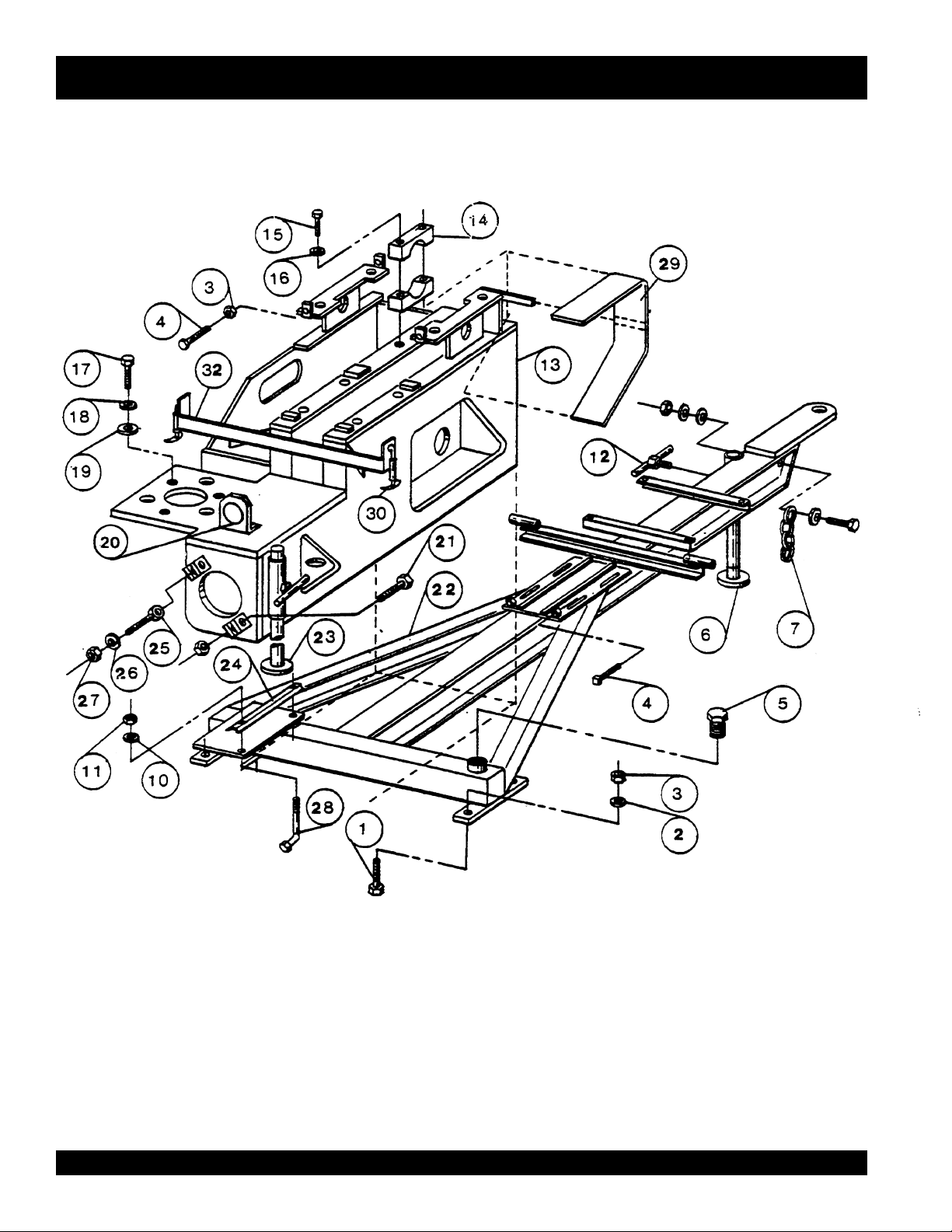
C-30HD — FRAME
PAGE 28 — C-30HD — PARTS & OPERATION MANUAL — REV. #4 (03/06/01)
Page 29

C-30HD — FRAME
C-30HD CONCRETE PUMP
FRAME
NO. PART NO. PART NAME QTY. REMARKS
1 EM117 BOLT, HEX 1/2-13X2 4
2 EM923346 WASHER, LOCK 1/2" ........................................ 4 ........................ REPLACES EM606
3 EM406 NUT, HEX 1/2-13 4
4 EM130 BOLT, SQ. HEAD 1/2-13X2 1/2" 5
5 EM20349 OILER PLUG 1
6 EM14137 FRONT STAND ASSY (OLD STYLE) ............... 1 ........................ PRIOR TO: 12-31-96
6 EM25610 SWIVEL JACK STAND....................................... 1 ........................ S/N 970101 & ABOVE
6A EM508530 SUPPORT SWIVEL JACK .................................1 ........................ S/N 970101 & ABOVE
7 EM20135 SAFETY CHAIN 1
12 EM14138 TEE HANDLE ASSY 2
13 EM14100 PUMP BOX ASSY 1
14 EM14116 JOURNAL BLOCK 4
15 EM963180 BOLT, HEX 3/4-10X5 ......................................... 4 ........................ REPLACES EM131
16 EM923350 WASHER, LOCK 3/4" 4
17 EM104 BOLT, HEX 5/8-11X2 3
18 EM602 WASHER, LOCK 5/8 3
19 EM620 WASHER, WILLIAM 5/8 3
20 EM26536 TAIL LIGHT 1
21 EM963614 BOLT, HEX 3/4-10X3 2
22 EM14142 FRAME ASSEMBLY 1
23 EM14136 REAR STAND ASSY 1
24 EM14711 BATTERY HOLD DOWN 1
25 EM14165 WILLIAMS RE9B, 3/4X4 2
26 EM619 WASHER, WILLIAM 3/4" 2
27 EM968446 NUT, HEX 3/4-10 4
28 EM145 BOLT, HEX 1/4-20X11 2
29 EM14119 CHAIN GUARD 1
30 EM929028 HOOD LATCH.................................................... 2 ........................ REPLACES EM20107-1
32 EM14120 HOOD REST ASSY 1
EM26117 LUBE PLATE KIT ............................................... 1 ........................ NOTE: THIS KIT IS USED TO
ENCLOSE THE FRAME TO CREATE A
SPLASH TYPE LUBRICATION SYSTEM.
(CONTACT FACTORY FOR DETAILS)
C-30HD — PARTS & OPERATION MANUAL — REV. #4 (03/06/01) — PAGE 29
Page 30

C-30HD — GASOLINE ENGINE CONTROL
3#
6A
35
PAGE 30 — C-30HD — PARTS & OPERATION MANUAL — REV. #4 (03/06/01)
Page 31

C-30HD — GASOLINE ENGINE CONTROL
C-30HD CONCRETE PUMP
GASOLINE ENGINE
NO. PART NO. PART NAME QTY. REMARKS
1 EM147 BOLT, 1/2-13X2.1/2" 4
2 EM923346 WASHER, LOCK 1/2" ................................ 4 ............. REPLACES EM606
3 EM406 NUT, HEX 1/2-13" 4
4 EM14705 POSITIVE CABLE 1
5 EM20720 NEGATIVE CABLE 1
6 EM14710 BATTERY 12V 1
6A EM509755 BATTERY BOX 1 S/N ABOVE 980401
7 EM140 BOLT, 1/4-20X5/8" 2
8 EM20705 RELAY 1
9 EM968435 HEX NUT, 1/4-20" ...................................... 2 ............. REPLACES EM400
10 EM600 WASHER, LOCK 1/4" 2
11 EM123 BOLT, 3/8-16X1.1/4" 1
12 EM612 WASHER, LOCK 3/8" 1
13 EM968009 NUT, HEX 3/8-16 1
14 EM20714 LINKAGE 1
15 EM924028 PIN, COTTER 3/32X7/8" ........................... 2 ............. REPLACES EM707
16 EM979 DECAL, STARTER 1
17 EM26792 100 FT. EXTENSION 1
18 EM977 DECAL, CHOKE 1
19 EM40711 3 WAY SWITCH 1
20 EM946 DECAL, REMOTE CONTROL 1
21 EM26736 STARTER 1
22 EM978 DECAL,TAIL LIGHT 1
23 EM980 DECAL, THROTTLE 1
24 EM976 DECAL, IGNITION 1
25 EM20701 ENGINE 30 HP WISE VH4D 1
26 EM26788 REMOTE CORD ASSY 1
27 EM26793 ADAPTER 1
28 EM20713 EXTENSION 1
29
30 EM20704 CLAMP BRACKET ASSY 1
31
32
33
34
35 EM16754 SWITCH 1
EM20709 SOLENOID 1
*
EM14728 SOLENOID ASSY COMLETE ................... 1 ............. INCLS. ITEMS W/
EM20711 SOLENOID SPRING 1
*
EM20710 SOLENOID PLUNGER 1
*
EM20709-2 RUBBER BOOT 1
*
EM456 NUT, NYLOCK 5-40 1
*
*
C-30HD — PARTS & OPERATION MANUAL — REV. #4 (03/06/01) — PAGE 31
Page 32

C-30HD — DIESEL ENGINE CONTROL
PAGE 32 — C-30HD — PARTS & OPERATION MANUAL — REV. #4 (03/06/01)
Page 33

C-30HD — DIESEL ENGINE CONTROL
C-30HD CONCRETE PUMP
DIESEL ENGINE CONTROL-C-30HD
NO. PART NO. PART NAME QTY. REMARKS
1 EM968011 NUT, LOCK 1/2-13 .................................... 4 ............. REPLACES EM404
2 EM923035 WASHER, FLAT 1/2”.................................. 4 ............. REPLACES EM609
3 EM963692 BOLT, 1/2-13X1.1/2” .................................. 4 ............. REPLACES EM110
4 EM621 WASHER, WILLIAM 1/2” 2
5 EM20733 DIESEL ENGINE, HATZ Z790 1
6 EM620 WASHER, PLAIN 5/8 ................................. 4 ............. REPLACES EM14347
7 EM176 BOLT SOCKET HD, 3/8-16X1.1/4” 2
8 EM138 BOLT, HEX 3/8-16X1 3
9 EM612 WASHER, LOCK 3/8” 2
10 EM14602 BRACKET ASSY 1
11 EM20791 CONTROL BOX 1
12 EM175 BOLT SOCKET HD, 3/8-16X1.1/4 2
13 EM20719 BATTERY 12V 1
14 EM16707 GROUND CABLE 1
15 EM20721 POSITIVE CABLE 1
16 EM20735 EXHAUST CLAMP 1 REPLACES EM176847
17 EM20734 EXHAUST ELBOW 1
18 EM20790 LINKAGE ASSY 1
19 EM20790-5 SPRING 1
20 EM601 LOCK WASHER 2
21 EM20761 YOKE BAR 1
22 EM20758-1 YOKE SUPPORT 1
23 EM272 BOLT, ALLEN HEAD 8X30MM 2
24 EM20731 CONTROL CHAIN
25 EM26732 ENGINE CONTROL .................................. 1 ............. REPLACES EM20730
26 EM20763 INLINE FILTER 1
27 EM923035 WASHER, FLAT 1/2” .................................. 2 ............. REPLACES EM609
28 EM26788 REMOTE CONTROL 1
29 EM940062 NUT, LOCK 1/2-14 .................................... 1 ............. REPLACES EM26789-3
30 EM20727 CONTROL BRKT. 1
31 EM26789 RECEPTAGLE 1
32 EM146 BOLT, ALLEN HEAD 12X25MM S.H. 2
33 EM20709 SOLENOID 1
34 EM963550 BOLT, 1/4-20X3/4 ...................................... 4 ............. REPLACES EM112
35 EM16730 RETURN SPRING ..................................... 1 ............. REPLACES EM20728
36 EM600 WASHER, LOCK 1/4 4
37 EM26792 CORD ASSY, 100 FT. 1
38 EM26793 ADAPTER FOR CORD 1
39 EM20760 ROD 1
NOTE: EffectiveS/N971001
The throttle control has been updated
— Consult factory for part numbers.
C-30HD — PARTS & OPERATION MANUAL — REV. #4 (03/06/01) — PAGE 33
Page 34

NOTE PAGE
PAGE 34 — C-30HD — PARTS & OPERATION MANUAL — REV. #4 (03/06/01)
Page 35

C-30HD — MANIFOLD ASSEMBLY
Note: EXPLODED VIEW OF
PAGES 34 & 35
C-30HD — PARTS & OPERATION MANUAL — REV. #4 (03/06/01) — PAGE 35
Page 36

C-30HD — CONCRETE DELIVERY
PAGE 36 — C-30HD — PARTS & OPERATION MANUAL — REV. #4 (03/06/01)
Page 37

C-30HD — CONCRETE DELIVERY
C-30HD CONCRETE PUMP
CONCRETE DELIVERY
NO. PART NO. PART NAME QTY. REMARKS
281 EM23837 REDUCER, 3X2 .......................................................... 1 .................... PRIOR TO JULY 1, 1990
281 EM28004-DD REDUCER, 3X2 .......................................................... 1 .................... AFTER JULY 1, 1990
282 EM963180 BOLT, 3/4-10X5 .......................................................... 2 .................... REPLACES EM131
283 EM14809 EXHAUST GATE ......................................................... 1 ....................PRIOR TO JULY 1, 1990
283 EM14850 EXHAUST GATE ......................................................... 1 .................... AFTER JULY 1, 1990
284 EM968446 NUT, HEX 3/4-10 ........................................................ 2 .................... REPLACES EM407
285 BALL INSERT ............................................................. 1 .................... SEE NOTE
286 EM18801 “O” RING 5
287 EM14818 STEEL BALL, 4” 1
288 EM968266 NUT, JAM 3/4-16 ........................................................ 6 ..................... REPLACES EM421
289 EM618 WASHER, SPECIAL 3/4 6
290 EM18409 “O” RING 6
291 EM14801 PRIMARY VALVE 1
292 EM136 STUD, 3/4-16X8 3
293 EM137 T-BOLT, 3/4-10X14 2
294 EM14817 VALVE SEAT 1
295 EM14810 JOLTER SPRING 1
296 EM14845 CLAMP ARM 1
297 EM23839 3” COUPLING “B” VIC ................................................ 1 .................... PRIOR TO JULY 1, 1990
297 EM28904 3" COUPLING "B" HD ................................................ 1 .................... AFTER JULY 1, 1990
298 EM23840 3” COUPLING S/J VIC ................................................ 1 ....................PRIOR TO JULY 1, 1990
298 EM28904 3" COUPLING "B" HD ................................................ 1 ..................... AFTER JULY 1, 1990
299 EM23838 ELBOW, 3”-90° ........................................................... 1 ....................PRIOR TO JULY 1, 1990
299 EM23946 ELBOW. 3"-90° ........................................................... 1 .................... AFTER JULY 1, 1990
300 EM135 BOLT, 1-1/4-12X6 1
301 EM14819A MANIFOLD ASSY 1
302 EM968446 NUT, HEX 3/4-10 ........................................................ 2 .................... REPLACES EM407
303 EM619 WASHER, WILLIAM 3/4 2
304 EM18804 STEEL BALL, 4 1/2” 1
305 BALL INSERT ............................................................. 1 .................... SEE NOTES
306 EM160 BOLT, 3/8-16X3/4 1
307 EM451 NUT, LOCK 1-1/4-12 1
Not Shown in diagram: 4" Urethane Ball (P/N EM26817); 4" Seat (P/N EM26816)
Notes on item #285 — Machines prior to July 1, 1990
use P/N 18803 Ball Insert; On machines after July 1,
1990, P/N 18803 was replaced by the Duraseat P/N
14843. This new seat is more durable and can be used
on older units.
Notes on item #305 — Machines prior to July 1, 1990
use P/N 18806 insert (used in conjunction with 14817
seat); On machines after July 1, 1990, these parts are
replaced by 14842 Duraseat.
C-30HD — PARTS & OPERATION MANUAL — REV. #4 (03/06/01) — PAGE 37
Page 38

C-30HD — CLUTCH ASSEMBLY — ALL MACHINES PRIOR TO S/N 960801 (August 1996)
203
199
200
201
202
C-30HD CONCRETE PUMP
CLUTCH ASSEMBLY
ALL MACHINES UP TO S/N 960801
NO. PART NO. PART NAME QTY. REMARKS
196 EM14320 CLUTCH ASSEMBLY (8" DIA) ................................... 1 .................... INCLS. ALL ITEMS W/
197*EM918050 CLUTCH SPRING ...................................................... 2 .................... REPLACES EM26309
198*EM923346 1/2 LOCK WASHER.................................................... 1 ....................REPLACES EM606
199*EM963564 1/2-13X1 1/4 HEX BOLT ............................................ 1 .................... REPLACES EM139
200*EM628 SPECIAL WASHER 1
201*EM26321 ROTOR ASSEMBLY 1
202*EM26310 CLUTCH LINING 1
203*EM26322 CLUTCH HOUSING 1
204*EM902204 CLUTCH BEARING .................................................... 2 .................... REPLACES EM26311
205*EM926066 RETAINING RING ....................................................... 2 .................... REPLACES EM801
206*EM926053 RETAINING RING ....................................................... 1 .................... REPLACES EM800
*
C-30HD — CLUTCH ASSEMBLY — ALL MACHINES S/N 960801 THRU 980400 (August 1996)
Note: CLUTCH ASSY (BLM 6") P/N
EM14320A HAS BEEN REPLACED
BY CLUTCH ASSY P/N EM14320
(8" CLUTCH)
THE CLUTCH PACK FOR 6"
CLUTCH IS STILL AVAILABLE
UNDER P/N EM60HB
PAGE 38 — C-30HD — PARTS & OPERATION MANUAL — REV. #4 (03/06/01)
Page 39

NOTE PAGE
C-30HD — PARTS & OPERATION MANUAL — REV. #4 (03/06/01) — PAGE 39
Page 40

C-30HD — CRANKSHAFT ASSEMBLY
PAGE 40 — C-30HD — PARTS & OPERATION MANUAL — REV. #4 (03/06/01)
Page 41

C-30HD — CRANKSHAFT ASSEMBLY
C-30HD CONCRETE PUMP
CRANKSHAFT ASSEMBLY
NO. PART NO. PART NAME QTY. REMARKS
1 EM14305 CRANKSHAFT 1
2 EM14322 SPACER 1
3 EM14326 “O” RING 2
4 EM14325 BEARING CONE 2
5 EM14323 BEARING CONE SPACER 1
6 EM14324 BEARING CUP 1
7 EM14303 BEARING BLOCK 1
8 EM14302 CAM BUSHING SPACER 1
9 EM14306 CRANKSHAFT KEY 2
10 KEY ............................................................ 1 ............. INCLUDED W/ ITEMS 12 +16
11 EM14300 CAM WELDMENT 1
12 EM14301 CAM BUSHING 1
13 EM14304 CAM BEARING 1
14 EM30190 SET COLLAR 1
15 EM14307 SPROCKET, 60 TOOTH 1
16 EM14309 BUSHING 1
C-30HD — PARTS & OPERATION MANUAL — REV. #4 (03/06/01) — PAGE 41
Page 42

C-30HD — CRANKSHAFT ASSEMBLY
156
PAGE 42 — C-30HD — PARTS & OPERATION MANUAL — REV. #4 (03/06/01)
Page 43

C-30HD — CRANKSHAFT ASSEMBLY
C-30HD CONCRETE PUMP
CRANKSHAFT ASSEMBLY
NO. PART NO. PART NAME QTY. REMARKS
132 EM14322 SPACER 1
133 EM14326 “O” RING 2
134 EM923350 LOCK WASHER .......................................................... 2 ....................REPLACES EM610
135 EM968446 NUT, HEX 3/4-10 ........................................................ 4 .................... REPLACES EM407
136 EM702 SCREW, SET HALF DOG POINT 3/8-16X3/4 2
137 EM916001 LUBE FITTING, 1/8-27 NPT ...................................... 2 ....................REPLACES EM16179
138 EM14300 CAM WELDMENT 1
139 EM968013 NUT, HEX 5/8-11 ........................................................ 4 .................... REPLACES EM419
140 EM923348 WASHER, LOCK 5/8 .................................................. 3 .................... REPLACES EM602
141 EM620 WASHER, WILLIAMS 5/8 4
142 EM128 BOLT, HEX 5/8-11X4 2
143 EM14304 CAM BEARING 1
144 EM175 BOLT, SOC HD 3/8-16X1 1/4 1
145 EM14301 CAM BUSHING 1
146 EM14302 CAM BUSHING SPACER 1
147 EM14325 BEARING CONE 2
148 EM14303 BEARING BLOCK 1
149 EM129 BOLT, HEX 3/4-10X8 1/2 2
150 EM14324 BEARING CUP 1
151 EM14323 BEARING CONE SPACER 1
152 EM104 BOLT, HEX 5/8-11X2 1
153 EM14306 CRANKSHAFT KEY 2
154 EM14305 CRANKSHAFT 1
155 EM703 SCREW, SET 3/8-16X3/8 2
156 EM30139 SET COLLAR 1
C-30HD — PARTS & OPERATION MANUAL — REV. #4 (03/06/01) — PAGE 43
Page 44

C-30HD — COUNTER SHAFT ASSEMBLY
PAGE 44 — C-30HD — PARTS & OPERATION MANUAL — REV. #4 (03/06/01)
Page 45

C-30HD — COUNTER SHAFT ASSEMBLY
C-30HD CONCRETE PUMP
COUNTER SHAFT ASSEMBLY
NO. PART NO. PART NAME QTY. REMARKS
155 EM14307 SPROCKET, 60 TOOTH 1
156 EM14308 CHAIN 1
157 EM14309 BUSHING 1
158 EM26313 OFFSET LINK 1
159 EM702 SCREW, SET 3/8-16X3/4 1
160 EM703 SCREW, SET 3/8-16X3/8 1
161 EM14318 SPROCKET, 13 TOOTH 1
161 EM14319 BUSHING 1
163 EM14312 COUNTER SHAFT 1
164 EM968011 NUT, HEX 1/2-13 ........................................................ 4 .................... REPLACES EM404
165 EM923346 WASHER, LOCK 1/2 .................................................. 4 .................... REPLACES EM606
166 EM14315 BELT, BP90 (GASOLINE) 1
167 EM900127 BELT, B87 (DIESEL) ................................................... 2 .................... REPLACES EM14321
168 EM14314 BUSHING 1
169 EM14313 PULLEY 1
170 EM14316 KEY 1
171 EM14311 CAM BEARING 2
172 EM124 BOLT, HEX 1/2-13X4 4
173 EM621 WASHER, WILLIAM 1/2 4
174 EM916001 LUBE FITTING ........................................................... 2 ....................REPLACES EM16179
175 EM14317 KEY 1
176 EM161 BOLT, HEX 5/16-18X1 3
177 EM492378 BOLT, HEX 3/8-16X1 3/4 ............................................ 3 .................... REPLACES EM177
178 EM123 BOLT, HEX 3/8-16X1 1/4 3
179 EM26314 CONNECTING LINK 1
C-30HD — PARTS & OPERATION MANUAL — REV. #4 (03/06/01) — PAGE 45
Page 46

C-30HD — COMPENSATOR PISTON ROD
PAGE 46 — C-30HD — PARTS & OPERATION MANUAL — REV. #4 (03/06/01)
Page 47

C-30HD — COMPENSATOR PISTON ROD
C-30HD CONCRETE PUMP
COMPENSATOR PISTON ROD
NO. PART NO. PART NAME QTY. REMARKS
104 EM18800 PUMPING CYLINDER 1
105 EM968446 NUT, HEX 3/4-10 ........................................................ 4 .................... REPLACES EM407
106 EM14413 FACE PLATE 2
107 EM18409 “O” RING 4
108 EM14412 BUSHING 2
109 EM14411 PISTON CUP 2
110 EM14408 BRONZE RING 2
111 EM14410 RING & FELT HOLDER 2
112 EM16493 FELT RING 2
113 EM20816 “O” RING 2
114 EM903162 BEARING CONE ........................................................ 4 .................... REPLACES EM20815
115 EM916001 LUBE FITTING ........................................................... 2 ....................REPLACES EM16179
116 EM14806 PISTON GUIDE 1
117 EM903163 BEARING CUP ........................................................... 2 .................... REPLACES EM20812
118 EM20814 BUSHING 2
119 EM20813 SPACER 2
120 EM14805 ROD END 1
121 EM14331 BACKING PLATE 1
122 EM14333 RETURN SPRING 1
123 EM14332 GUIDE ROD 1
124 EM14105 ANCHOR PLATE 1
125 EM20412 OILER FITTING MINI-BARB 2
126 EM14409 OILER PLATE 2
127 EM14407 “O” RING 2
128 EM916001 LUBE FITTING ........................................................... 3 ....................REPLACES EM16179
129 EM14336 PISTON GUIDE 1
130 EM14334 COMPENSATOR SPRING 1
131 EM704 PIN, LG SPIRAL 1/2X2 1
132 EM14335 PISTON ROD 1
C-30HD — PARTS & OPERATION MANUAL — REV. #4 (03/06/01) — PAGE 47
Page 48

C-30HD — CONNECTING ROD ASSEMBLY 20328 (OLD STYLE)
A
PAGE 48 — C-30HD — PARTS & OPERATION MANUAL — REV. #4 (03/06/01)
Page 49

C-30HD — CONNECTING ROD ASSEMBLY 20328 (OLD STYLE)
C-30HD CONCRETE PUMP
CONNECTING ROD ASSEMBLY EM20328 (OLD STYLE)
NO. PART NO. PART NAME QTY. REMARKS
A EM20328 CONNECTING ROD ASSY ........................................ 1 .................... INCLS. ALL ITEMS W/
87 EM14808 PISTON ROD WELDMENT 1
88 EM968446 3/4-10 HEX NUT ........................................................ 1 ....................REPLACES EM407
89 EM14807 PUMPING CYLINDER 1
90
91
92
93
94
95
96
97
98
99
100*EM20328-1 CONNECTING ROD 1
101 EM703 SCREW, SET LG CUP 3/8-16X3/8 2
103 EM20338 SPACER 1
EM402150 SPACER ...................................................................... 2 .................... REPLACES EM20329
*
EM2330 O-RING 2
*
EM402999 SPACER ...................................................................... 2 .................... REPLACES EM20331
*
EM916004 LUBE FITTING ........................................................... 1 .................... REPLACES EM16153
*
EM903175 BEARING .................................................................... 1 .................... REPLACES EM20333
*
EM402149 BUSHING .................................................................... 1 .................... REPLACES EM20332
*
EM402996 SPACER ...................................................................... 1 .................... REPLACES EM20335
*
EM20336 “O” RING 2
*
EM903176 BEARING .................................................................... 1 .................... REPLACES EM20337
*
EM916001 LUBE FITTING ........................................................... 1 .................... REPLACES EM16179
*
*
C-30HD — PARTS & OPERATION MANUAL — REV. #4 (03/06/01) — PAGE 49
Page 50

C-30HD — CONNECTING ROD ASSEMBLY 20328T (NEW STYLE)
A
PAGE 50 — C-30HD — PARTS & OPERATION MANUAL — REV. #4 (03/06/01)
Page 51

C-30HD — CONNECTING ROD ASSEMBLY 20328T (NEW STYLE)
C-30HD CONCRETE PUMP
CONNECTING ROD ASSEMBLY EM20328T (NEW STYLE)
NO. PART NO. PART NAME QTY. REMARKS
A EM20328T CONNECTING ROD ASSY ........................................ 1 .................... INCLS. ALL ITEMS W/
87 EM14808 PISTON ROD WELDMENT 1
88 EM968446 NUT, HEX 3/4-10 ........................................................ 1 .................... REPLACES EM407
89 EM14807 PUMPING CYLINDER 1
90
91
92
93
94
95
96
97
98
99
100*EM20364 CONNECTING ROD 1
101 EM703 SCREW, SET, LG CUP 3/8-16X3/8 1
102 EM702 SCREW, SET, POG POINT 3/8-16X3/8 1
103 EM20338 SPACER 1
EM20816 O-RING 2
*
EM903162 BEARING CONE ........................................................ 2 .................... REPLACES EM20815
*
EM20813 SPACER 1
*
EM916004 LUBE FITTING ........................................................... 1 .................... REPLACES EM16153
*
EM903175 BEARING CUP ........................................................... 1 .................... REPLACES EM20333
*
EM20814 BUSHING 1
*
EM402996 SPACER ...................................................................... 1 .................... REPLACES EM20335
*
EM20336 “O” RING 2
*
EM903176 BEARING .................................................................... 1 .................... REPLACES EM20337
*
EM916001 LUBE FITTING ........................................................... 1 .................... REPLACES EM16179
*
*
C-30HD — PARTS & OPERATION MANUAL — REV. #4 (03/06/01) — PAGE 51
Page 52

C-30HD — ROCKER ASSEMBLY
PAGE 52 — C-30HD — PARTS & OPERATION MANUAL — REV. #4 (03/06/01)
Page 53

C-30HD — ROCKER ASSEMBLY
C-30HD CONCRETE PUMP
ROCKER ASSEMBLIES
NO. PART NO. PART NAME QTY. REMARKS
68 EM202 BOLT, HEX 1-8X6 LG 1
69 EM133 BOLT, HEX 1-14X2 LG 2
70 EM627 WASHER, STAR 1” 3
71 EM14329 ROCKER ARM SHAFT 1
72 EM916001 LUBE FITTING, 1/8-27 NPT ...................................... 3 .................... REPLACES EM16179
73 EM20326-2 BUSHING 4
74 EM105 BOLT, HEX 1-14X6 LG 2
75 EM603 WASHER, LOCK 1” 3
76 EM14328 ROCKER ARM ASSEMBLY 1
77 EM417 NUT, LOCK 1-14 3
78 EM402434 BUSHING .................................................................... 1 .................... REPLACES EM20346
79 EM20347 SPACER 3
80 EM903092 CAM ROLLER ............................................................ 1 .................... REPLACES EM20345
81 EM23044 GREASE BOLT 1
82 EM14846 CAM ROCKER ARM 1
83 EM405 NUT, LOCK 3/4-10 1
84 EM402456 OILER PLUG 1
86 EM963180 BOLT, HEX 3/4-10X5 LG ............................................ 1 .................... REPLACES EM131
87 EM923157 CAM OILER SEAL SPACER ....................................... 1 ....................REPLACES EM607
C-30HD — PARTS & OPERATION MANUAL — REV. #4 (03/06/01) — PAGE 53
Page 54

EM14409
C-30HD — COMPENSATING SPRING ASSEMBLY
EM18409
EM14335
EM16179
EM20412
EM14334
EM20415
NOTE: If it is necessary to replace the spring, remove the piston
head assembly which allows the guide weldment to be
removed from the piston rod.
EM16179
NOTE: Grease the compensator piston rod
daily at both fittings. Failure to grease
regularly may cause the piston rod to
“seize” in the guide tube resulting in
severe pulsations of material in the hose.
PAGE 54 — C-30HD — PARTS & OPERATION MANUAL — REV. #4 (03/06/01)
EM14806
EM704
EM20812
EM16179
Page 55

EM903092
EM14105
(PART OF PUMP BOX ASSEMBLY)
C-30HD — RETURN SPRING ASSEMBLY
EM14846
EM14805
EM14332
EM14334
EM14333
EM14331
C-30HD — PARTS & OPERATION MANUAL — REV. #4 (03/06/01) — PAGE 55
Page 56

C-30HD — OIL SYSTEM AND FUEL SYSTEM
PAGE 56 — C-30HD — PARTS & OPERATION MANUAL — REV. #4 (03/06/01)
Page 57

C-30HD — OIL SYSTEM AND FUEL SYSTEM
C-30HD CONCRETE PUMP
OIL SYSTEM AND FUEL SYSTEM
NO. PART NO. PART NAME QTY. REMARKS
176 EM20426 MINI BARB ELBOW 2
177 EM20427 FUEL LINE A/R
178 FUEL TANK .......................................... 1 ........................... SEE NOTE
179 EM401 NUT, HEX 5/16-18 6
180 EM968354 WASHER, LOCK 5/16 ......................... 6 ........................... REPLACES EM601
181 EM923023 WASHER, FLAT 5/16 ...........................10 ......................... REPLACES EM614
182 EM101 BOLT, HEX 5/16-18X1 1/2 4
183 FUEL TANK STRAP .............................2 ........................... SEE NOTE
184 EM20787 FUEL TANK CAP ................................. 1 ........................... SEE NOTE FOR PLASTIC FUEL TANK
185 EM20349 OIL PLUG 1
186 EM20412 MINI BARB FITTING 3
187 EM20415 CLEAR PLASTIC TUBE A/R
188 EM20417 NIPPLE 1
189 EM20418 TEE FITTING 1
190 EM911004 STREET ELBOW .................................1 ........................... REPLACES EM20416
191 EM20421 METERING VALVE 2
192 EM14401 ELECTRIC OIL PUMP 1
193 EM963030 BOLT, HEX 5/16-18X1 .........................2 ........................... REPLACES EM163
194 EM923027 WASHER, FLAT 3/8 ............................. 2 ........................... REPLACES EM611
195 EM14198 OIL RESERVOIR 1
196 EM1440 INSERT FITTING 1
Notes: Item #178 and 183 (A) — Machines prior to 1993
use P/N 14701 Fuel Tank (8 gal. capacity) and #14703
Fuel Tank Straps (two required). (B) — Machines after
1993 use P/N 14205 Fuel Tank (18 gal. capacity) and
#16185 Fuel Tank Straps (two required). (C) —
Machines after 2/1/95 use P/N 14205P Plastic Fuel
Tank (18 gal. capacity); P/N 2108 Gas Cap. Fuel tank
straps not required. Note: interchangeable with P/N
14205.
C-30HD — PARTS & OPERATION MANUAL — REV. #4 (03/06/01) — PAGE 57
Page 58

C-30HD — CENTRAL GREASE LUBRICATION PANEL EFFECTIVE S/N 970101
FITTING LOCATION AND PLASTIC HOSE LENGTH
EM509306 PANEL ASSY COMPLETE
NOTE: P/N
EM16495
GREASE LINE
(sold per foot)
EM505489 HOSE GREASE ZERK-12 REQUIRED
EM505490 45° GREASE ZERK-1 REQUIRED
POSITION LOCATION LENGTH OF LINES
1 ....................................................FLANGE BEARING (CRANKSHAFT) ................................................... 28"
2 ....................................................CONNECTING ROD ............................................................................ 31"
3 ....................................................CAM BEARING .................................................................................... 28"
4 ....................................................STEEL BEARING BLOCK (SQUARE) .................................................. 34"
5 ....................................................ROCKER ARM UPPER (CRANKSHAFT SIDE) .................................... 10"
6 ....................................................PILLOW BLOCK BEARINGS (COUNTERSHAFT) ............................... 15"
7 ....................................................LOWER ROCKER ARM ....................................................................... 28"
8 ....................................................ROCKER ARM LOWER (CHAIN SIDE) ................................................ 26"
9 ....................................................PILLOW BLOCK BEARINGS (COUNTERSHAFT) ............................... 20"
10 ..................................................ROCKER ARM UPPER (PULLEY SIDE) .............................................. 20"
11 ..................................................CONNECTING ROD LOWER .............................................................. 40"
12 ..................................................PISTON GUIDE .................................................................................... 42"
13 ..................................................PISTON ROD .......................................................................................
TOTAL LENGTH OF LINES REQUIRED .............................................. 364"
42"
PAGE 58 — C-30HD — PARTS & OPERATION MANUAL — REV. #4 (03/06/01)
Page 59

NOTE PAGE
C-30HD — PARTS & OPERATION MANUAL — REV. #4 (03/06/01) — PAGE 59
Page 60

C-30HD — AXLE INSTALLATION
A
212
PAGE 60 — C-30HD — PARTS & OPERATION MANUAL — REV. #4 (03/06/01)
Page 61

C-30HD — AXLE INSTALLATION
C-30HD CONCRETE PUMP
AXLE INSTALLATION
NO. PART NO. PART NAME QTY. REMARKS
A EM26615A TIRE ASSY ................................................................. 2 .................... INCLS. ALL ITEMS W/
209 EM26518 HUB CAP 2
210*EM20603 TIRE 2
211*EM20602 WHEEL 2
212 EM20601 HUB ASSEMBLY ......................................................... 2 ....................INCLS. ALL ITEMS W/
213 EM14600 AXLE 1
214 EM705 PIN, COTTER 3/16X1 1/2 2
215# EM26305 GREASE SEAL 2
216
# EM903168 INNER BEARING ........................................................ 2 .................... REPLACES EM26301
217# EM903169 INNER CUP ................................................................ 2 ....................REPLACES EM26303
# EM26300 HUB 2
218
219
# EM903012 OUTER CUP ............................................................... 2 ....................REPLACES EM26304
220# EM903113 OUTER BEARING ...................................................... 2 ....................REPLACES EM26302
221# EM26329 WASHER 2
222# EM968481 CASTLE NUT ............................................................. 2 .................... REPLACES EM420
223# EM26306 DUST COVER 2
224# EM26519 NUT 12
225# EM20612 STUD 12
*
#
C-30HD — PARTS & OPERATION MANUAL — REV. #4 (03/06/01) — PAGE 61
Page 62

C-30HD — HOPPER AND HOOD
69
PAGE 62 — C-30HD — PARTS & OPERATION MANUAL — REV. #4 (03/06/01)
Page 63

C-30HD — HOPPER AND HOOD
C-30HD CONCRETE PUMP
HOPPER AND HOOD
NO. PART NO. PART NAME QTY. REMARKS
56 DURASEAT ................................................ 1 ............. SEE NOTE BELOW
57 EM18801 “O” RING 1
58 EM923348 5/8” LOCK WASHER .................................. 3 ............. REPLACES EM602
59 EM104 5/8-11X2 LG HEX BOLT 3
60 EM14140 HOOD 1
61 EM14141 HOPPER 1
62 EM14159 HOPPER SCREEN 1
63 EM14140-17 DOOR HINGE 1
64 EM14140-16 HOOD DOOR 1
65 EM14140-4 HOOD DOOR SUPPORT 2
66 EM14140-5 HOOD SUPPORT BRKT 2
67 EM406 1/2-13 HEX NUT 2
68 EM124 1/2-13X4 LG HEX BOLT 2
69 508659 LATCH 1
EM14164 KIT, DECAL SAFETY ................................. 1 ............. COMPONENTS NOT SHOWN
Note on item 56: A — Machines, built after July 1, 1990
use Duraseat P/N 14843 — This new seat is more
durable and can be used on older units.
C-30HD — PARTS & OPERATION MANUAL — REV. #4 (03/06/01) — PAGE 63
Page 64

C-30MG — SCALED DOWN MANIFOLD/CYLINDER KIT MODEL C-30MG
The above manifold/cylinder and piston assembly can be
ordered as a kit to be installed on model C-30K, C-30SP or
model C-30D pumps. This unit has a volume delivery of 4 to
13 cu. yds. per hour. When installed on a standard pump, the
unit will pump brick mortar as well as 1/2” minus aggregate
mixes in excess of
volume pump for numerous applications such as high-rise
grouting-spancrete-mud jacking-capping wells-tunnel
grouting-pumping pilings and shotcrete.
Note: If the above assembly is installed on model C-30D pumps
it will be necessary to replace the compensator piston rod
assembly with the new style used on the model C-30K, and
model C-30 HD.
200 ft. vertical. It is a high pressure-low
PAGE 64 — C-30HD — PARTS & OPERATION MANUAL — REV. #4 (03/06/01)
Page 65

NOTE PAGE
C-30HD — PARTS & OPERATION MANUAL — REV. #4 (03/06/01) — PAGE 65
Page 66

C-30MG — MANIFOLD ASSEMBLY C-30MG
PAGE 66 — C-30HD — PARTS & OPERATION MANUAL — REV. #4 (03/06/01)
Page 67

C-30MG — MANIFOLD ASSEMBLY C-30MG
C-30MG CONCRETE PUMP
MANIFOLD ASSEMBLY-C30-MG
NO. PART NO. PART NAME QTY. REMARKS
1 EM14832 PUMPING CYLINDER 1
2 EM14827 MANIFOLD 1
3 EM14824 STEEL BALL, 3-1/4 1
4 EM14422 SQ. SEAL 1
5 EM14823 VALVE SEAT 1
6 EM14822 VALVE HOUSING 1
7 EM803 BALL STOP STUD 3
8 EM618 WASHER, 3/4 6
9 EM968266 NUT, JAM 3/4-16 ....................................... 6 ............. REPLACES EM421
10 EM14833 ADAPTOR 1
11 EM802 RETAINING RING 1
12 EM14829 O-RING 1
13 EM18801 O-RING 1
14 EM14824 STEEL BALL, 3-1/4 1
15 EM14826 INSERT 1
16 EM18801 O-RING 1
17 EM14823 VALVE SEAT 1
18 EM14836 VALVE SEAT ADAPT. 1
19 EM963180 BOLT, 3/4-10X5 ......................................... 1 ............. REPLACES EM131
20 EM968446 NUT, HEX 3/4-10 ....................................... 1 ............. REPLACES EM407
21 EM14832 COMP CYLINDER 1
22 EM14828 REDUCER 1
23 EM135 BOLT, 1/4-20X6 1
24 EM14845 CLAMP ARM 1
25 EM14810 SPRING 1
26 EM14830 O-RING 1
27 EM160 BOLT, 3/8-16X3/4 1
28 EM14829 O-RING 1
29 EM802 RETAINING RING 1
30 EM14833 ADAPTOR 1
31 EM18409 O-RING 6
32 EM618 WASHER, 3/4 6
33 EM968266 NUT, JAM 3/4X16 ...................................... 6 ............. REPLACES EM421
34 EM451 NUT, HEX 1-1/4-12 1
C-30HD — PARTS & OPERATION MANUAL — REV. #4 (03/06/01) — PAGE 67
Page 68

C-30MG — PISTON HEAD COMPONENTS
PAGE 68 — C-30HD — PARTS & OPERATION MANUAL — REV. #4 (03/06/01)
Page 69

C-30MG — PISTON HEAD COMPONENTS
C-30MG CONCRETE PUMP
PISTON HEAD COMPONENTS C30-MG
NO. PART NO. PART NAME QTY. REMARKS
1 EM968446 NUT, HEX 3/4-10 ....................................... 2 ............. REPLACES EM407
2 EM14420 FACE PLATE 2
3 EM18409 O-RING 2
4 EM14418 SLEEVE 2
5 EM14419 PISTON CUP 2
6 EM14417 BACK PLATE 2
7 EM14416 FELT SPACER 2
8 EM14423 FELT RING 2
9 EM14421 OILER PLATE 2
10 EM18409 O-RING 2
11 EM14808 PISTON ROD 2
C-30HD — PARTS & OPERATION MANUAL — REV. #4 (03/06/01) — PAGE 69
Page 70

C-30SP — OPTIONAL SCREW CONVEYOR AND TORQUE LIMITER MODEL C30-SP
PAGE 70 — C-30HD — PARTS & OPERATION MANUAL — REV. #4 (03/06/01)
Page 71

C-30SP — OPTIONAL SCREW CONVEYOR AND TORQUE LIMITER MODEL C30-SP
C-30SP CONCRETE PUMP
OPTIONAL SCREW CONVEYOR AND TORQUE LIMITER C30-SP
NO. PART NO. PART NAME QTY. REMARKS
1 EM14175 HOPPER 1
2 EM968011 NUT, HEX 1/2-13 ....................................... 2 ............. REPLACES EM404
3 EM923346 WASHER, LOCK 1/2 ................................. 2 ............. REPLACES EM606
4 EM26108 SCREW FEEDER 1
5 EM147 BOLT, HEX 1/2-13X2.1/2 2
6 EM26108-4 PLUG 1
7 EM721 KEY 1
8 EM14170 EXTENSION 1
9 EM14340 SPROCKET CHAIN 1
10 EM14338 TORQUE LIMITER 1
11 EM14341 SPROCKET 1
12 EM14716 BUSHING 1
13 EM14339 SPROCKET 1
14 EM26359 DRIVE SHAFT 1
15 EM720 KEY 1
16 EM916001 OILER ........................................................ 1 ............. REPLACES EM16179
17 EM26109 CHAIN GUARD 1
18 EM147 BOLT, HEX 1/2-13X2.1/2 8
19 EM923346 WASHER, LOCK 1/2 ................................. 8 ............. REPLACES EM606
20 EM621 WASHER, WILLIAM 4
21 EM18138 SEAL SPACER 8
22 EM18135 FLANGE BEARING 2
23 EM18138 SEAL SPACER 8
24 EM18136 SPACER PLATE 2
25 EM18137 SHAFT SEAL 2
26 EM18136 SPACER PLATE 2
27 EM18137 SHAFT SEAL 2
C-30HD — PARTS & OPERATION MANUAL — REV. #4 (03/06/01) — PAGE 71
Page 72

RECOMMEMDED SHOTCRETE SYSTEM
For swimming pool construction, ditch lining, tunnel lining, slope stabilization, etc.
PAGE 72 — C-30HD — PARTS & OPERATION MANUAL — REV. #4 (03/06/01)
Page 73

RECOMMEMDED SHOTCRETE SYSTEM
NO. PART NO. PART NAME QTY. REMARKS
1 EM28904........... 3" “B” COUPLING
2 EM23946........... 3"-90° ELBOW
3 EM28903........... 2 1/2" S/J COUPLING
4 EM28005DD ..... 3"X 2 1/2 REDUCER
5 EM28061........... 2 1/2"X 10FT. PIPE
6 EM24849........... 2 1/2"X 50FT. HOSE
7 EM28001DD ..... 2 1/2"X 2" REDUCER
8 EM23815D ........ 2 1/2"X 2" REDUCER
W/AIR VIBRATOR
9 EM28902 ........... 2" S/J COUPLING
10 EM23101........... AIR VIBRATOR
11 EM28131........... 2"X 2 ELBOW
12 EM24841........... 2"X 25 FT. HOSE
13 EM23808D ........NOZZLE ASSEMBLY
14 EM23806........... 1 3/8" NOZZLE TIP
15 EM23807........... 1 1/4" NOZZLE TIP
General recommendations
■
If the site will permit, use steel pipe from the pump
to the pool perimeter. It will reduce line pressures
which is highly recommended.
■
The vibrator on the reducer by the pool improves
pumpability.
■
Turn both air vibrators off whenever the pump is
stopped to prevent separation of mix.
■
The air vibrators are low consumption (4.2 scfm).
■
Leave the air on at the nozzle when the pump is
stopped to prevent clogging of air the hoses in the
air insert.
■
Use item #11 (steel elbow) at the edge of the pool
to prevent collapse of the rubber hose, which can
cause blockage.
C-30HD — PARTS & OPERATION MANUAL — REV. #4 (03/06/01) — PAGE 73
Page 74

C-30HD SHOTCRETE ACCESSORIES
PAGE 74 — C-30HD — PARTS & OPERATION MANUAL — REV. #4 (03/06/01)
Page 75

C-30HD SHOTCRETE ACCESSORIES
C-30HD CONCRETE PUMP
SHOTCRETE ACCESSORIES
NO. PART NO. PART NAME QTY. REMARKS
302 EM26107 HOPPER SCREEN 1
303 EM23101-1 AIR VIBRATOR 1
304 EM132 BOLT, 1/2-13X2 2
305 EM23407 AIR HOSE 1
306 EM23408 BUSHING 1
307 EM23411 VALVE 1
308 EM912073 NIPPLE 2
309 EM23409 COUPLING 1
310 EM923346 WASHER, 1/2 LOCK ................................. 2 ............. REPLACES EM606
311 EM406 NUT, HEX 1/2-13 2
312 EM23818 2"X25' GROOVED HOSE
EM24841 2"X25' RAISED HOSE
EM23845 2"X50' GROOVED HOSE
313*EM23802 ADAPTER 1
314*EM23803 GUN BODY 1
315*EM20816 “O” RING 1
316*EM23804 AIR INSERT 1
317*EM23805 NOZZLE CLAMP 1
318*EM23806 NOZZLE TIP, 1 3/8" 1
319*EM23807 NOZZLE TIP, 1 1/4" 1
320*EM911076 STREET ELBOW ....................................... 1 ............. REPLACES EM23412
321 AIR HOSE NOT SUPPLIED BY MAYCO
322 EM23808 NOZZLE ASSEMBLY ................................. 1 ............. INCLS. ITEMS W/
*
NOTE: Use a 1 3/8" rubber nozzle tip for a wide spray
pattern. Use a 1 1/4" rubber nozzle tip for a narrow spray
pattern. DO NOT INSTALL THE NOZZLE AT THE END OF
THE HOSE UNTIL THE FIRST MATERIAL HAS PASSED
THROUGH THE ENTIRE HOSE LENGTH.
Disassemble and clean the nozzle assembly
thoroughly after each job. Grease all threads before reassembly. Do not close the air valve when pumping is
stopped as a continued air flow keeps the air passages
clean.
C-30HD — PARTS & OPERATION MANUAL — REV. #4 (03/06/01) — PAGE 75
Page 76

C-30HD — SERVICE PROCEDURES
1. CRANKSHAFT AND CAM ASSEMBLY PROCEDURE
A. Set bearing block (part #EM14303) into hydraulic press.
Place bearing cup into bearing block and press in evenly.
Bearing cup should be aligned equally on both sides of bearing
block.
B. Set crankshaft into hydraulic press with the long end
towards the top. Install spacer (part #EM14322), O-ring (part
#EM14326) and bearing cone (part #EM14325) onto
crankshaft. Place bearing block on crankshaft until the bearing
cone is riding in the bearing cup. Insert bearing cone spacer
(part #EM14323) onto crankshaft and inside bearing block.
Install second bearing cone until it is seated inside bearing
cup. Place O-ring and spacer (part #EM14302) on crankshaft.
Set cam weldment on top of spacer. Install crankshaft key and
cam key on cam bushing (part #EM14301). Slide cam bushing
down crankshaft and align the bushing, cam and crankshaft.
Install sleeve over crankshaft and align with hydraulic press.
Install cam bushing bolts loosely. Press bushing down onto
bearing assembly. Leaving pressure on the bushing, tighten
cam bolts evenly to 40-50 foot pounds. Release pressure on
the bushing, re-apply pressure to bushing and tighten bolts
evenly to 40-50 foot pounds. Repeat procedure 3 to 4 times.
After bushing is tight into cam, remove from hydraulic press.
Remove one bolt at a time, using Loctite, install bolts and
torque to 65-70 foot pounds. Counter sink set screw hole and
install dog point set screw and second set screw both with
Loctite.
C. Place cam bearing onto crankshaft keeping bearing loose.
*Note: Make sure the eccentric lock is facing toward the outside
of the pumping unit.
D. Set crankshaft assembly into the pump box and align both
bearing assemblies with the pump box mountings.
E. After crankshaft assembly is securely fastened to the pump
box, place sprocket (part #EM14307) onto the cam side of
the crankshaft assembly. Install bushing (part #EM14309) into
sprocket. Align sprocket with sprocket on countershafts and
tighten bolts.
F. Install chain part #EM14308. To adjust, loosen locknuts on
pusher bolts and tighten chain to approximately 1/2” slack in
the chain. Once chain is adjusted properly, tighten down
locknuts.
2. BALL AND SEAT REPLACEMENT PROCEDURE
A. Remove 3”x 2” reducer and 3” elbow from the pump outlet.
Remove exhaust gate and Y-manifold (secondary manifold).
Check ball seat and ball stop pin for wear. If any wear is
detected, the part should be replaced. Remove T-manifold
(primary manifold). Check all parts for wear. Remove hopper
and hopper seat and inspect.
B. Loosen the piston nuts and remove the piston cup assembly
and cylinders. Inspect all parts for wear and replace parts with
excessive wear. Check oiler pump for proper operation.
C. Clean all parts thoroughly, removing all foreign material and
concrete slurry. Once parts are clean, install concrete cylinders.
Place oiler plate O-ring in place and coat with oil. Install small
O-ring on piston rod. Run oiler line through the cylinders and
connect in the oiler fitting on the oiler plate. Push oiler plate
into cylinder. Install ring and felt holder, soak felt ring in oil,
then install around felt holder in cylinder. Make sure the bronze
ring is flat, then push it up flush with the ring and felt holder.
Coat piston cup with oil and push it inton the cylinder. Install
bushing into center of piston cup. Put small O-ring on rod, place
face plate on rod and tighten down securely. Repeat these
procedure on the opposite cylinder.
D. Thoroughly check T-manifold, ball stoppings and both steel
balls for wear. Insert an O-ring in the top flange and in the
leading edge of the manifold. Put the manifold onto the primary
side of the pump and install bolts leaving them loose.
E. Check Y-manifold for wear, install all O-rings, ball stop pin,
ball and seat. Align and install Y-manifold to T-manifold and
cylinder assembly. Tighten Y-manifold bolts first before
tightening T-manifold bolts. After manifolds are tight, check Orings for slippage.
F. Insert seat into frame hole directly above the T-manifold.
The seat orifice should fit inside the frame itself, then the seat
sits on top of the orifice. On the dura-seat, set the big end of
the seat in the frame. The seat, or the small part of the duraseat, fits into the bottom of the hopper.
G. After tightening the manifold bolts and inserting the seats
in place, set the hopper over the seat and align the bolt holes.
Tighten bolts, check O-ring and seat for alignment.
H. Check exhaust gate for wear, install and align gate onto Ymanifold. Insert O-ring into exhaust gate flange and close gate.
Lock down lever and adjust clamp arm.
I. Install 3” elbow and 3”x 2” reducer. Fill hopper half full and
check for leaks.
PAGE 76 — C-30HD — PARTS & OPERATION MANUAL — REV. #4 (03/06/01)
Page 77

C-30HD — SERVICE PROCEDURES
3. CLUTCH LINING REPLACEMENT (FOR EM14320
CLUTCH ASSEMBLY ONLY)
A. Remove worn out lining and rivets. Check clutch springs
and flyweights for wear.
B. Cut 1/8” off of each end of clutch lining. Slide lining into place.
Insert one rivet into clutch lining hole. (Make sure rivet goes
from inside out.) Wedge a flathead screwdriver between clutch
flyweight and rivet head. Adjust screwdriver so that the rivet
sticks out from the clutch housing approximately 1/8 of an inch.
With a flat punch, pen the ends on the rivet so that it locks in
place with the clutch housing. Repeat this procedure for all
remaining clutch rivets.
PREVENTIVE MAINTENANCE
It is extremely important to maintain this pump due to
the highly abrasive nature of concrete material.
Mayco recommends checking after every 8 hours of operation.
1. Engine; Refer to engine owner’s manual.
2. Inspect all drive components for loose or worn bolts.
3. Drive belt/chain should be checked to remove all slack. Refer
to adjustment procedure.
4. Always carry extra “O” rings.
5. Keep entire pump clean of concrete to prevent build-up.
6. Always grease all fittings daily. Use only premium grade
grease. *Note: Over greasing will not damage machine.
C-30HD — PARTS & OPERATION MANUAL — REV. #4 (03/06/01) — PAGE 77
Page 78

C-30HD — SERVICE INFORMATION MANUFACTURING CHANGES
EM14845
EM135
When ordering the new Manifold
P/N EM14819, the following items
are necessary to complete the new
Clamp Arm Assembly:
EM451...................Nut, Hex 1-1/4-12
EM14810...............Jolter Spring
EM14845...............Clamp Arm
EM135...................Bolt
EM451
EM14841-1
EM14810
EM14819-2 EM14841-1
Manifold Assembly
Part No. EM14819
Standard Equipment on all new C-
30HD models as of March 1989.
PAGE 78 — C-30HD — PARTS & OPERATION MANUAL — REV. #4 (03/06/01)
Page 79

C-30HD — SERVICE INFORMATION MANUFACTURING CHANGES
NEW ROCKER ARM ASSEMBLY PART NO. EM14846
Interchanges with Plaster Pump
Standard Equipment on all new C-30HD
models as of July 1, 1990
Part No. EM20342
Old Rocker Arm Assembly
Interchanges with Plaster Pump.
NO LONGER AVAILABLE.
C-30HD — PARTS & OPERATION MANUAL — REV. #4 (03/06/01) — PAGE 79
Page 80

C-30HD — SERVICE INFORMATION MANUFACTURING CHANGES
EM20714
EM20715
ENGINE RPM (GAS)
IDLE 950 RPM +/- 50
MAX. 2525 RPM +/- 85
New Remote Control Assembly
Conversion: Part No. EM14728
ENGINE RPM (DIESEL)
IDLE 1050 RPM +/- 50
MAX. 2525 RPM +/- 25
Adjustment
Make sure the rod is screwed completely into the
carburetor bellcrank and the nut is locked down. The
rod should be aligned in the center of the tube
assembly by shimming the solenoid inside the clamp
assembly so there is no binding. The solenoid
should be pushed toward the carburetor and the
spring completely compressed. Then allow the
spring to push the solenoid back through the clamp
0.75 inch and tighten the clamp. The solenoid is not
adjusted. Be sure to coat the rod and tube with
grease.
PAGE 80 — C-30HD — PARTS & OPERATION MANUAL — REV. #4 (03/06/01)
Page 81

C-30HD — SERVICE INFORMATION: REMOTE CONTROL
1. Turn Bell Crank on carburetor with Swivel End up. Bell Crank
2. Drill .156 dia. hole through Bell Crank swivel on Throttle
side of carburetor. Insert Rod & Spring assembly P/N
EM14729 and fasten with cotter pin. Carburetor
3. Insert linkage P/N EM20714 into Bell Crank on solenoid
side of carburetor and fasten with nut.
4. Insert linkage P/N EM20714 into extension on Remote
Control unit and bolt bracket P/N EM20704
on clutch side of engine.
C-30HD — PARTS & OPERATION MANUAL — REV. #4 (03/06/01) — PAGE 81
Page 82

C-30HD — REMOTE CONTROL SCHEMATIC
PAGE 82 — C-30HD — PARTS & OPERATION MANUAL — REV. #4 (03/06/01)
Page 83

C-30HD — REMOTE CONTROL SCHEMATIC
C-30HD — PARTS & OPERATION MANUAL — REV. #4 (03/06/01) — PAGE 83
Page 84

C-30HD — SERVICE INFORMATION LINKAGE ADJUSTMENT — OLD STYLE SOLENOID
(OBSOLETE)
SIDE VIEW FROM STARTER SIDE OF ENGINE
EM14706
EM16701
EM26730
P/N EM26730
EM26315
EM14707
Important
Adjust linkage as follows:
1. Energize the solenoid which will “bottom” the solenoid
plunger.
2. Screw eyebolt into bell crank swivel until all slack is
removed from chain, and “idle set screw” is full idle
position. Note: Remove gas line to carburetor to permit
easy installation of eye bolt in bell crank.
EM14708
3. Tighten jam-nut to prevent eye bolt from unscrewing.
PAGE 84 — C-30HD — PARTS & OPERATION MANUAL — REV. #4 (03/06/01)
Page 85

C-30HD — SERVICE INFORMATION: TORQUE LIMITER (MODEL C30-SP ONLY)
(Overload Safety Device Installed on Screw Conveyor
Shaft)
While pumping, if the Screw Conveyor at the bottom of the
hopper is fouled or stopped because of rocks, the Torque Limit
slips to prevent chain breakage.
If this condition exists, stop the pump and rotate the large
pulley by hand in reverse direction to free the Screw.
If the rock blockage is severe, it may be necessary to
disconnect the Drive Chain and turn the Screw Conveyor Shaft
using a wrench at the end nearest to the Jolter Cam.
Reconnect the chain and resume pumping.
C-30HD — PARTS & OPERATION MANUAL — REV. #4 (03/06/01) — PAGE 85
Page 86

C-30HD — SERVICE INFORMATION: BEARING INSTALLATION
After the cam bushing is installed as per instructions below,
remove the three “dog type” allen set screws (B) to allow
detents to be drilled. Use a 9/32” drill to “detent” half (minimum
1/8” deep). Then “chase” the threads with a 3/8-16 bottom tap
and blow out the chips after drilling, to be certain that the “dog
type” allen set screws bottom in the detents to prevent the
taper bushing from sliding laterally. If this procedure is not
followed closely the heavy loading of the bearing during
pumping operations causes the Timken cone bearings to
create lateral forces which will move the taper bushing and
allow the Timken cone bearings to separate from the race
and subsequently fail.
Caution: Position the ‘O’ ring on the O.D. of the bearing spacer
during assembly to assure proper bearing adjustment.
Note: It is important that the bearing assembly is installed
properly.
1. Install the bearing components on the crankshaft making
full contact with the back side of the crank disc as indicated by
the symbol
2. Install the bushing in the cam weldment and slide it onto
the crankshaft until contact is made with the bearing spacer.
3. Tighten the 3 allen socket head screws “A” while exerting
pressure on the bushing towards the bearing spacer.
4. Drill (detent) the shaft under the allen set screws “B” to
prevent the bushing from the sliding away from the bearning
spacer when the pump is under a load.
.
*
PAGE 86 — C-30HD — PARTS & OPERATION MANUAL — REV. #4 (03/06/01)
Page 87

C-30HD — SERVICE INFORMATION CONNECTING ROD ASSEMBLY EM20328T (NEW STYLE)
NOTE: Inspect the bolt regularly as it
must remain tight to hold the bearing
assebly on the crabk throw pin.
(EM104)
(EM602)
EM20335-
EM20338 —
EM20336 —
EM20337 —
EM20816 —
EM20336-
EM20364-
EM20333-
EM20816-
C-30HD — PARTS & OPERATION MANUAL — REV. #4 (03/06/01) — PAGE 87
Page 88

C-30HD — SERVICE INFORMATION: CONCRETE PISTON HEAD LUBRICATION SYSTEM
Illustration represents the oil
pressurized system (oil pump)
The Mayco model C30-HD pump is the only pump available
utilizing a direct oil pressurized system (oil pump) and enclosed
lubrication box. This combination will prolong the piston cup
life and meet environmental standards.
1. Oil injection system — Check the reservoir every 8 hours.
Use a good grade of SAE 30 oil. *Note: Use SAE 10 wt. in cool
weather. When the piston cups are new, open the metering
valves to full open or approximately 15 drops of oil per minute
drip from the rear of each cylinder. (For the first 25 yards)
2. Lubrication box — We recommend utilizing soluble type oil
(water and oil mixture). The oil level should be periodically
checked and maintained at a height of 5 inches or one-half of
the cylinder height.
*Note: IMPORTANT! During freezing temperatures, completely
drain the water box and cover hopper.
As the piston cups naturally wear, fine cement particles will
accumulate in the box. Once the concrete paste reaches a
height of 3/4 inches from the bottom, the box should be drained
and cleaned, and the pump should be serviced.
*Note: If preferred, the oil pump may be disconnected. (Contact
Mayco Service Department)
PAGE 88 — C-30HD — PARTS & OPERATION MANUAL — REV. #4 (03/06/01)
Page 89

C-30HD — SERVICE INFORMATION RETURN SPRING ADJUSTMENT PROCEDURE
Do not tighten 3/4” bolt completely so that rod end will
be free to move.
The above return spring is installed to eliminate shock
and stress between the cam roller and the cam weldment
when the pump is in operation. If spring EM14333 is
removed or replaced for any reason, maintain the backing
plate dimension as shown to produce proper pre-loading
of the spring for a smooth performance.
C-30HD — PARTS & OPERATION MANUAL — REV. #4 (03/06/01) — PAGE 89
Page 90

C-30HD — SERVICE INFORMATION BELT AND CHAIN ADJUSTMENT
PILLOW BLOCK BEARING BOLTS
PULLEY
LOCK NUTS
PUSHER
BOLTS
CHAIN
BELTS
3/4" MAX.
DEFLECTION
1. Loosen the pillow bearing bolts only to the point where the
bolts will remain snug.
2. Unlock the two pusher bolt lock nuts.
3. Turn each pusher bolt clockwise an equal amount until the
chain is to proper adjustment of approximately 3/8" to 1/2”
slack in the chain. It is very important that the pulley side and
the chain side (pillow block bearings) are within 1/16” of an
equal distance.
4. This distance can be checked by using a tape measure or
a straight edge ruler, measuring from the inside of the pusher
bolt bracket to the face of the pillow block bearing.
5. The drive chain should be adjusted regularly to remove all
slack. Once all slack is removed, do not over-adjust, as this
will overload the shaft bearings. A slack chain on the crank
drive creates backlash and shock loads on the shafts and
bearings which results in shorter wear/life of the drive
components. Lubricate the chain regularly. Note-it is advisable
to carry a spare chain and master links for replacement in the
field if necessary.
PUSHER BOLT BRACKET
6. Drive belts should be regularly adjusted to prevent slippage.
To adjust the belts, loosen the engine mounting bolts and
move the engine until there is a maximum 3/4" deflection in
the belts, retighten the engine mounting bolts.
7. Frequent inspections should be made on all drive
components to make certain that all bolts and nuts remain
tight.
NOTE: PRIOR TO ADJUSTING CHAIN — PLACE THE
LOBE OF THE CAM IN THE DOWN POSITION.
THE CHAIN SHOULD HAVE 83 RIVITS
INCLUDES (ONE EACH, HALF LINK AND FULL
LINK)
PAGE 90 — C-30HD — PARTS & OPERATION MANUAL — REV. #4 (03/06/01)
Page 91

ROLLER CHAIN — APPLICATION INFORMATION
Roller chain properly selected, installed and maintained is an
extremely versatile means of power transmission. It is possible,
however, to greatly reduce a chain’s life and even induce failure if
the chain is abused through improper installation, operating or
maintenance procedures. In certain applications, failure can lead to
personal injury or property damage.
Recommendations and comments on how to get the most from
your roller chain drive are given on the following pages.
WORKING LOADS
UTS-Ultimate Tensile Strength-is the one time pull required to break
the chain. The Tensile Strength figures given in the Diamond catalog
are not allowed working loads. For single strand chain, the load
(pull) applied to the chain in service should never exceed 1/6th of
the UTS for the chain being used except as noted below.
It is possible to exceed the allowable working loads for a limited
number of cycles, but you should contact Diamond Chain Company
before this is considered. A roller chain should never be loaded
above 50% of UTS for even one cycle. To do so will damage
the chain structure and reduce its capacity.
The UTS or one time breaking load of multiple strand chain is the
UTS of a single strand chain times the number of strands; i.e., two
strand chain is twice as strong as single.
When allowable working loads are considered, however, the
capacity of each strand in a multiple strand chain is only 65% of the
single strand rating; thus, three-strand chain would rate not three
times single but only 1.95 times. This is because the chain load
cannot be exactly distributed across all three strands of the threestrand chain.
The chain should be installed so the slack span is properly tensioned.
To check chain tension, turn one sprocket to tighten the upper span
of the chain while holding the other sprocket fixed. The lack span
should have 4-6% of span length in the mid-span movement for
horizontal drives and 2-3% for vertical drives.
A roller chain’s capacity can be significantly reduced if it is twisted
or bent sideways in the direction of the pin axis. Exercise particular
care in alignment of hoist or other applications where loads are
suspended near personnel.
LUBRICATION
As a chain articulates in entering and leaving a sprocket,
relative movement between pin and bushing surfaces. These
surfaces wear causing chain elongation. If a lubricant film can
be maintained between the pin and bushing, the wear rate is
very slow and the chain wear life very long. Maintaining the oil
film is relatively simple at low speeds but becomes increasingly
difficult as the speed increases.
It is recognized that good lubrication is not possible in many
applications, so shorter wear life must be accepted in these
situations.
In general, chain wear leads to rough or unsatisfactory service
prior to actual chain breakage. Good lube can help to prevent
INSTALLATION AND DRIVE ALIGNMENT
chain failure by providing protection against rust or corrosion.
Rusting can allow pits to form in the surfaces of the chain parts
causing stress concentration points. This can lead to chain
failure at relatively low
loads.
The clearance between
pin and bushings is very
small, on the order of
.003 to .005 inches. A
lubricant must be thin
Chain and sprockets must be installed correctly. Sprockets must be
properly aligned and sprocket shafts must be parallel so the drive
will run in a plane perpendicular to them. Axial alignment should be
checked with a straight edge which will extend across the finished
sides of the sprockets. They should be true-running with minimum
wobble and eccentricity. The higher the drive speed, the more
important these details become.
enough to flow into the
chain. SAE 30 weight oil
is about right for room
temperature. Lighter oil
should be used for lower
ambients and heavier
for higher operating temperatures. Grease should not be used
as it cannot penetrate chain clearances.
there is
C-30HD — PARTS & OPERATION MANUAL — REV. #4 (03/06/01) — PAGE 91
Page 92

DIAMOND CHAIN COMPANY — ROLLER CHAIN APPLICATION INFORMATION
WHEN DISASSEMBLING OR ASSEMBLING CHAINS:
WARNING: — The components of a chain are hardened parts.
Striking these parts may cause metal chips to break off from
the chain or the tools used resulting in personal injury. During
all stages of chain disassembly and assembly, wear safety
glasses to prevent metal parts or chips from entering your
eyes and have personnel in the immediate area do likewise.
A. Pin Removal
1) If chain is of cotter pin- type construction, remove cotters.
2) If chain is riveted type construction, grind pin heads off so
pin ends are flush with the linkplate.
3) Drive pins out of linkplate using a Diamond pin extractor
Model #113 or 135. Some multiple strand chains or large
pitch models will require a hammer and punch or a press to
remove the pins.
WARNING
B. Installation of Coversides
Diamond coversides are manufactured three different ways:
(1) Slip Fit, (2) Modified Press Fit, and (3) Full Press Fit.
Modified and Full Press Fits require some patience and tools
to assemble and/or disassemble. Use vice grips, plumbers
pliers or a small hammer to drive coversides onto pins.
C. Installation of Spring Locks and Cotterpins
After coversides have been installed, install spring locks or
cotters (depending on chain design). Avoid using bent or
worn cotters or spring locks. After spring locks (or cotters)
are installed, lightly tap pin ends to position these parts snug
against the coverside for additional support.
WHEN INSTALLING CHAIN DRIVES ON EQUIPMENT:
WARNING — You may be seriously injured if you attempt to
install chain on equipment under power. Shut off power and
lock out gears and sprockets before attempting installation.
Once installed, the chain drive must be guarded to prevent
personal injury or properly damage in the event the chain
separates during operation. If chain drive is not guarded,
contact equipment manufacturer for recommendations on
guarding before using equipment.
Knowing more about how the chain is constructed may help
in assembly and disassembly. Further information may be
obtained by calling or writing Diamond Chain Company.
PAGE 92 — C-30HD — PARTS & OPERATION MANUAL — REV. #4 (03/06/01)
Page 93

Effective: July 1, 2000
TERMS AND CONDITIONS OF SALE — PARTS
PAYMENT TERMS
Terms of payment for parts are net 10 days.
FREIGHT POLICY
All parts orders will be shipped collect or
prepaid with the charges added to the invoice.
All shipments are F.O.B. point of origin.
Multiquip’s responsibility ceases when a
signed manifest has been obtained from the
carrier, and any claim for shortage or damage
must be settled between the consignee and the
carrier.
MINIMUM ORDER
The minimum charge for orders from Multiquip
is $15.00 net. Customers will be asked for
instructions regarding handling of orders not
meeting this requirement.
RETURNED GOODS POLICY
Return shipments will be accepted and credit
will be allowed, subject to the following
provisions:
1. A Returned Material Authorization must
be approved by Multiquip prior to shipment.
2. To obtain a Return Material Authorization,
a list must be provided to Multiquip Parts
Sales that defines item numbers,
quantities, and descriptions of the items
to be returned.
a. The parts numbers and descriptions
must match the current parts price
list.
b. The list must be typed or computer
generated.
c. The list must state the reason(s) for
the return.
d. The list must reference the sales
order(s) or invoice(s) under which
the items were originally purchased.
e. The list must include the name and
phone number of the person
requesting the RMA.
3. A copy of the Return Material
Authorization must accompany the return
shipment.
4. Freight is at the sender’s expense. All
5. Parts must be in new and resalable
6. The following items are not returnable:
7. The sender will be notified of any material
8. Such material will be held for 5 working
9. Credit on returned parts will be issued at
10. In cases where an item is accepted for
11. Credit issued will be applied to future
PRICING AND REBATES
parts must be returned freight prepaid to
Multiquip’s designated receiving point.
condition, in the original Multiquip package
(if any), and with Muiltiquip part numbers
clearly marked.
a. Obsolete parts. (If an item is listed
in the parts price book as being
replaced by another item, it is
obsolete.)
b. Any parts with a limited shelf life
(such as gaskets, seals, “O” rings,
and other rubber parts) that were
purchased more than six months
prior to the return date.
c. Any line item with an extended dealer
net price of less than $5.00.
d. Special order items.
e. Electrical components.
f. Paint, chemicals, and lubricants.
g. Decals and paper products.
h. Items purchased in kits.
received that is not acceptable.
days from notification, pending
instructions. If a reply is not received
within 5 days, the material will be returned
to the sender at his expense.
dealer net price at time of the original
purchase, less a 15% restocking charge.
which the original purchase document
can not be determined, the price will be
based on the list price that was effective
twelve months prior to the RMA date.
purchases only.
Prices are subject to change without prior
notice. Price changes are effective on a specific
date and all orders received on or after that date
will be billed at the revised price. Rebates for
price declines and added charges for price
increases will not be made for stock on hand
at the time of any price change.
Multiquip reserves the right to quote and sell
direct to Government agencies, and to Original
Equipment Manufacturer accounts who use
our products as integral parts of their own
products.
SPECIAL EXPEDITING SERVICE
A $20.00 to $50.00 surcharge will be added to
the invoice for special handling including bus
shipments, insured parcel post or in cases
where Multiquip must personally deliver the
parts to the carrier.
LIMITATIONS OF SELLER’S LIABILITY
Multiquip shall not be liable here under for
damages in excess of the purchase price of the
item with respect to which damages are
claimed, and in no event shall Multiquip be
liable for loss of profit or good will or for any
other special, consequential or incidental
damages.
LIMITATION OF WARRANTIES
No warranties, express or implied, are made
in connection with the sale of parts or trade
accessories nor as to any engine not
manufactured by Multiquip. Such warranties
made in connection with the sale of new,
complete units are made exclusively by a
statement of warranty packaged with such
units, and Multiquip neither assumes not
authorizes any person to assume for it any
other obligation or liability whatever in
connection with the sale of its products. A part
from such written statement of warranty, there
are no warranties, express, implied or statutory,
which extend beyond the description of the
products on the face hereof.
C-30HD — PARTS & OPERATION MANUAL — REV. #4 (03/06/01) — PAGE 93
Page 94

PARTS AND OPERATION MANUAL
HERE'S HOW TO GET HELP
PLEASE HAVE THE MODEL AND SERIAL NUMBER
ON-HAND WHEN CALLING
PARTS DEPARTMENT
800-427-1244 or 310-537-3700
FAX: 800-672-7877 or 310-637-3284
SERVICE DEPARTMENT/TECHNICAL ASSISTANCE
800-478-1244 or 310-537-3700
FAX: 310- 537-4259
WARRANTY DEPARTMENT
888-661-4279, or 310-661-4279
FAX: 310- 537-1173
MAIN
800-421-1244 or 310-537-3700
FAX: 310-537-3927
MULTIQUIP INC.
POST OFFICE BOX 6254
CARSON, CA 90749
310-537-3700 • 800-421-1244
FAX: 310-537-3927
E-MAIL: mq@multiquip.com
WWW: multiquip.com
Quebec, Canada • Manchester, UK • Rio De Janiero, BR • Guadalajara, MX
Atlanta • Boise • Dallas • Houston • Newark
 Loading...