

Page 1
OPERATION AND PARTS MANUAL
MODELS
C10SH8 (STEEL)
C10PH8 (PLASTIC)
CONCRETE MIXER
(HONDA GX240U1QA2 GASOLINE ENGINE
Revision #0 (03/06/09)
To fi nd the latest revision of this
publication, visit our website at:
www.stowmfg.com
THIS MANUAL MUST ACCOMPANY THE EQUIPMENT AT ALL TIMES.
Page 2
PROPOSITION 65 WARNING
Engine exhaust and some of
its constituents, and some dust created
by power sanding, sawing, grinding,
drillingandother construction activities
contains chemicals known to the State
of California to cause cancer, birth
defects and other reproductive harm.
Some examples of thesechemicals are:
Leadfromlead-basedpaints.
Crystallinesilica frombricks.
Cementandother masonry products.
Arsenicandchromiumfromchemically
treatedlumber.
Your risk from these exposures varies,
dependingon how often you dothistype
of work. To reduce your exposure to
these chemicals: work in aALWAYS
well ventilated area, and work with
approved safety equipment, such as
dust masks that are specially designed
to filter out microscopic particles.
PAGE 2 — C10SH8-PH8 CONCRETE MIXER • OPERATION AND PARTS MANUAL — REV. #0 (03/06/09)
Page 3
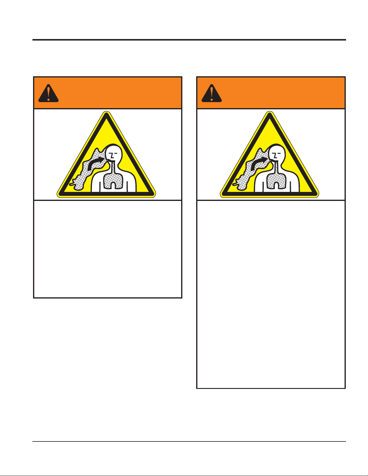
SILICOSIS/RESPIRATORY WARNINGS
WARNING
SILICOSIS WARNING RESPIRATORY HAZARDS
Grinding/cutting/drilling of masonry, concrete, metal and
other materials with silica in their composition may give
off dust or mists containing crystalline silica. Silica is a
basic component of sand, quartz, brick clay, granite and
numerous other minerals and rocks. Repeated and/or
substantial inhalation of airborne crystalline silica can
cause serious or fatal respiratory diseases, including
silicosis. In addition, California and some other
authorities have listed respirable crystalline silica as a
substance known to cause cancer. When cutting such
materials, always follow the respiratory precautions
mentioned above.
WARNING
Grinding/cutting/drilling of masonry, concrete, metal and
other materials can generate dust, mists and fumes
containing chemicals known to cause serious or fatal
injury or illness, such as respiratory disease, cancer,
birth defects or other reproductive harm. If you are
unfamiliar with the risks associated with the particular
process and/or material being cut or the composition of
the tool being used, review the material safety data
sheet and/or consult your employer, the material
manufacturer/supplier, governmental agencies such as
OSHA and NIOSH and other sources on hazardous
materials. California and some other authorities, for
instance, have published lists of substances known to
cause cancer, reproductive toxicity, or other harmful
effects.
Control dust, mist and fumes at the source where
possible. In this regard use good work practices and
follow the recommendations of the manufacturers or
suppliers, OSHA/NIOSH, and occupational and trade
associations. Water should be used for dust
suppression when wet cutting is feasible. When the
hazards from inhalation of dust, mists and fumes cannot
be eliminated, the operator and any bystanders should
always wear a respirator approved by NIOSH/MSHA for
the materials being used.
C10SH8-PH8 CONCRETE MIXER • OPERATION AND PARTS MANUAL — REV. #0 (03/06/09) — PAGE 3
Page 4

TABLE OF CONTENTS
C10SH8-PH8
Concrete Mixer
Proposition 65 Warning ........................................... 2
Silicosis/Respiratory Warnings ................................ 3
Table Of Contents .................................................... 4
Parts Ordering Procedures ...................................... 5
Safety Information .............................................. 6-10
Specifi cations ........................................................ 12
Dimensions ............................................................ 13
General Information ............................................... 14
Components .......................................................... 15
Basic Engine .......................................................... 16
Towing Guidelines .................................................. 17
Safety Chain Connection ....................................... 18
Inspection .............................................................. 19
Operation .......................................................... 20-21
Maintenance (Engine) ......................................22-23
Maintenance (Mixer) ......................................... 24-26
Troubleshooting (Engine) ....................................... 28
Troubleshooting (Mixer) ......................................... 29
Explanation Of Code In Remarks Column ............ 30
Suggested Spare Parts ......................................... 31
Component Drawings
Nameplates And Decals ................................... 32-33
Plastic Drum Assembly ..................................... 34-35
Steel Drum Assembly ....................................... 36-37
Yoke Assembly .................................................. 38-39
Frame Assembly ............................................... 40-41
Hub/Tire Assembly ........................................... 42-43
Cabinet Assembly ............................................. 44-45
Engine Assembly .............................................. 46-47
Terms And Conditions Of Sale — Parts ................ 48
NOTICE
Specifi cations and part numbers are subject to change
without notice.
PAGE 4 — C10SH8-PH8 CONCRETE MIXER • OPERATION AND PARTS MANUAL — REV. #0 (03/06/09)
Page 5
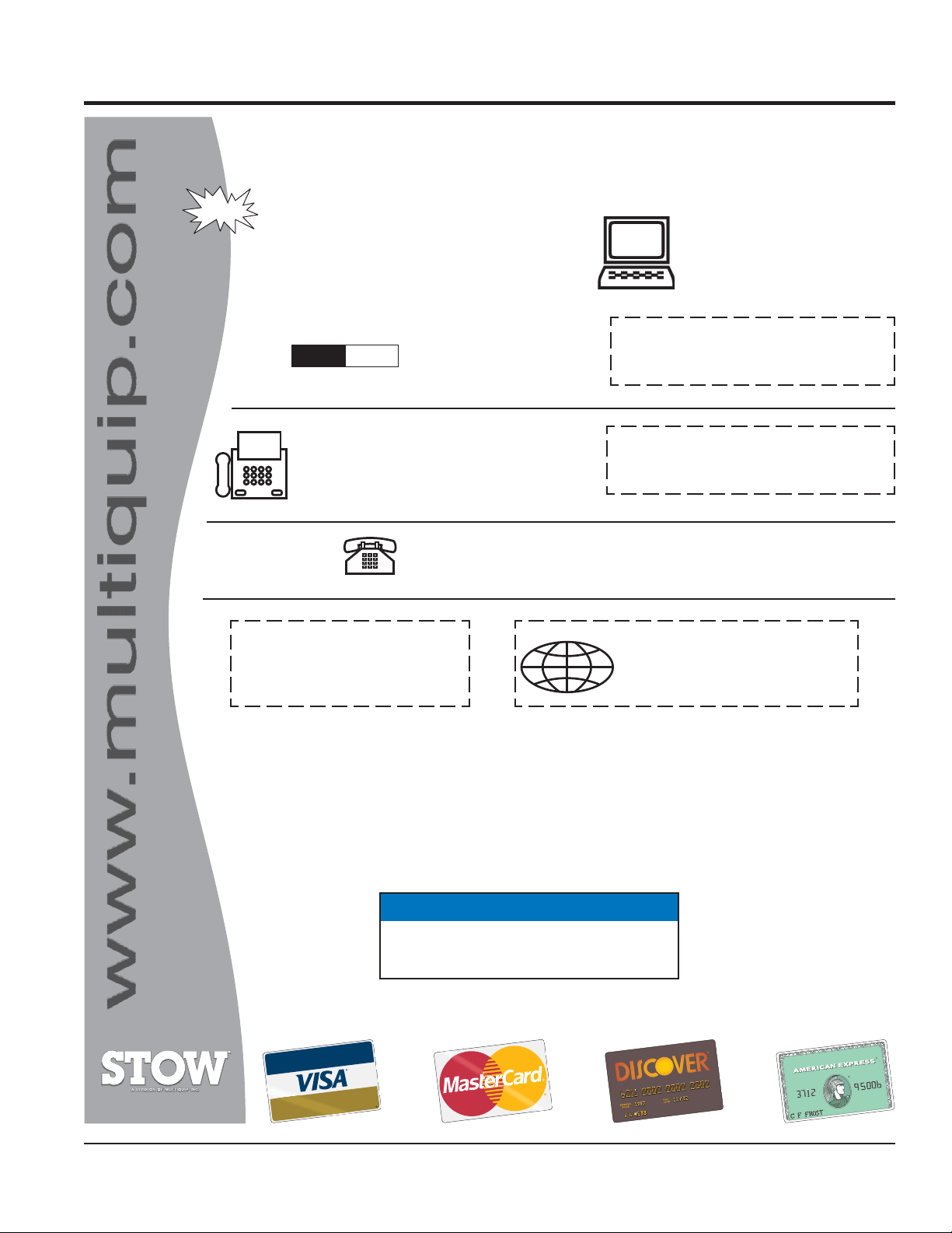
PARTS ORDERING PROCEDURES
www.multiquip.com
Ordering parts has never been easier!
Choose from three easy options:
January 1
Effective:
st
, 2006
Best Deal!
Order via Internet (Dealers Only):
Order parts on-line using Multiquip’s SmartEquip website!
■ View Parts Diagrams
■ Order Parts
■ Print Specifi cation Information
Goto www.multiquip.com and click on
Order Parts
Order via Fax (Dealers Only):
All customers are welcome to order parts via Fax.
Domestic (US) Customers dial:
1-800-6-PARTS-7 (800-672-7877)
Non-Dealer Customers:
Contact your local Multiquip Dealer for
parts or call 800-427-1244 for help in
locating a dealer near you.
to log in and save!
Order via Phone:
If you have an MQ Account, to obtain a Username
and Password, E-mail us at: parts@multiquip.
com.
To obtain an MQ Account, contact your
District Sales Manager for more information.
Use the internet and qualify for a 5% Discount
on Standard orders for all orders which include
complete part numbers.*
Note: Discounts Are Subject To Change
Fax your order in and qualify for a 2% Discount
on Standard orders for all orders which include
complete part numbers.*
Note: Discounts Are Subject To Change
Domestic (US) Dealers Call:
1-800-427-1244
International Customers should contact
their local Multiquip Representatives for
Parts Ordering information.
C10SH8-PH8 CONCRETE MIXER • OPERATION AND PARTS MANUAL — REV. #0 (03/06/09) — PAGE 5
When ordering parts, please supply:
❒ Dealer Account Number
❒ Dealer Name and Address
❒ Shipping Address (if different than billing address)
❒ Return Fax Number
❒ Applicable Model Number
❒ Quantity, Part Number and Description of Each Part
NOTICE
All orders are treated as Standard Orders and will
ship the same day if received prior to 3PM PST.
WE ACCEPT ALL MAJOR CREDIT CARDS!
❒ Specify Preferred Method of Shipment:
✓ UPS/Fed Ex ✓ DHL
■ Priority One ✓ Truck
■ Ground
■ Next Day
■ Second/Third Day
Page 6
SAFETY INFORMATION
Do not operate or service the equipment before reading
the entire manual. Safety precautions should be followed
at all times when operating this equipment.
Failure to read and understand the safety
messages and operating instructions could
result in injury to yourself and others.
SAFETY MESSAGES
The four safety messages shown below will inform you
about potential hazards that could injure you or others. The
safety messages specifi cally address the level of exposure
to the operator and are preceded by one of four words:
DANGER, WARNING, CAUTION or NOTICE.
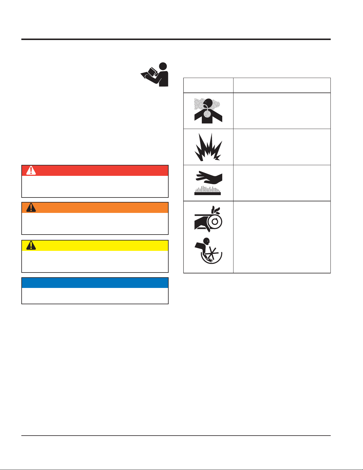
SAFETY SYMBOLS
DANGER
Indicates a hazardous situation which, if not avoided,
WILL result in DEATH or SERIOUS INJURY.
WARNING
Potential hazards associated with the operation of this
equipment will be referenced with hazard symbols which
may appear throughout this manual in conjunction with
safety messages.
Symbol Safety Hazard
Lethal exhaust gas hazards
Explosive fuel hazards
Burn hazards
Indicates a hazardous situation which, if not avoided,
COULD result in DEATH or SERIOUS INJURY.
CAUTION
Indicates a hazardous situation which, if not avoided,
COULD result in MINOR or MODERATE INJURY.
NOTICE
Addresses practices not related to personal injury.
Rotating parts hazards
PAGE 6 — C10SH8-PH8 CONCRETE MIXER • OPERATION AND PARTS MANUAL — REV. #0 (03/06/09)
Page 7
SAFETY INFORMATION
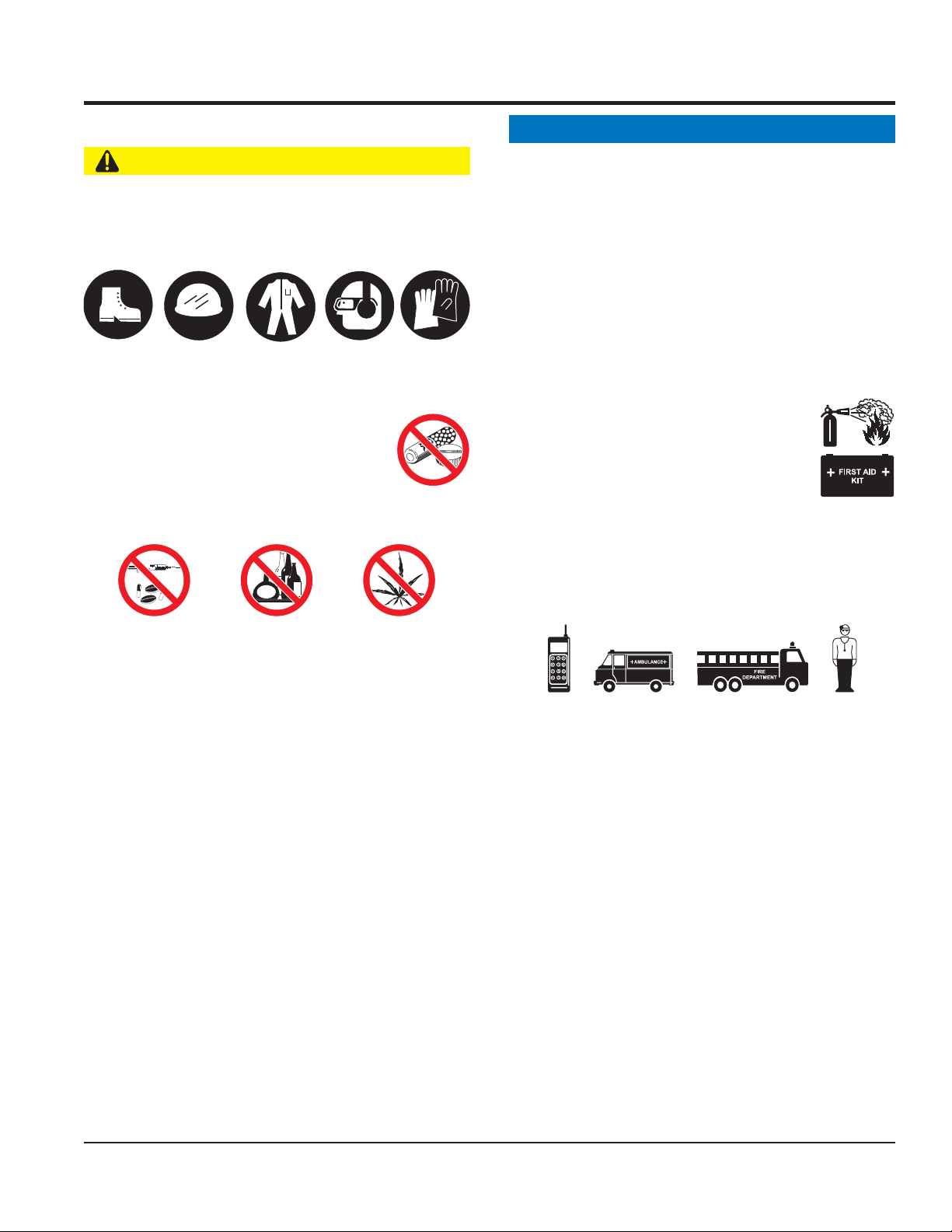
GENERAL SAFETY
CAUTION
NEVER operate this equipment without proper protective
clothing, shatterproof glasses, respiratory protection,
hearing protection, steel-toed boots and other protective
devices required by the job or city and state regulations.
Avoid wearing jewelry or loose fi tting clothes that may
snag on the controls or moving parts as this can cause
serious injury.
NEVER operate this equipment when not
feeling well due to fatigue, illness or when
under medication.
NEVER operate this equipment under the
infl uence of drugs or alcohol.
NOTICE
This equipment should only be operated by trained and
qualifi ed personnel 18 years of age and older.
Whenever necessary, replace nameplate, operation and
safety decals when they become diffi cult read.
Manufacturer does not assume responsibility for any
accident due to equipment modifi cations. Unauthorized
equipment modifi cation will void all warranties.
NEVER use accessories or attachments that are not
recommended by Multiquip for this equipment. Damage
to the equipment and/or injury to user may result.
ALWAYS know the location of the nearest
fi re extinguisher.
ALWAYS know the location of the nearest
fi rst aid kit.
ALWAYS know the location of the nearest phone or keep
a phone on the job site. Also, know the phone numbers
of the nearest ambulance, doctor and fi re department.
This information will be invaluable in the case of an
emergency.
ALWAYS clear the work area of any debris, tools, etc.
that would constitute a hazard while the equipment is
in operation.
ALWAYS check the equipment for loosened threads or
bolts before starting.
DO NOT use the equipment for any purpose other than
its intended purposes or applications.
C10SH8-PH8 CONCRETE MIXER • OPERATION AND PARTS MANUAL — REV. #0 (03/06/09) — PAGE 7
Page 8
SAFETY INFORMATION
MIXER SAFETY
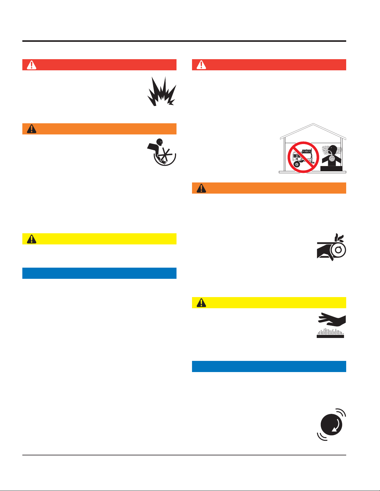
DANGER
NEVER operate the equipment in an explosive
atmosphere or near combustible materials. An
explosion or fi re could result causing severe
bodily harm or even death.
DO NOT mix fl ammable or explosive substances.
WARNING
NEVER place your hands inside the drum
while starting or operating this equipment.
NEVER disconnect any emergency
or safety devices. These devices are
intended for operator safety. Disconnection of these
devices can cause severe injury, bodily harm or even
death. Disconnection of any of these devices will void
all warranties.
Before operating mixer, ensure that safety grate is in
position and correctly fi tted.
CAUTION
NEVER lubricate components or attempt service on a
running machine.
NOTICE
ALWAYS keep the machine in proper running condition.
ALWAYS ensure mixer is on level ground before mixing.
Fix damage to machine and replace any broken parts
immediately.
DO NOT tip mixer onto drum mouth when the drum is
rotating.
Ensure the drum is rotating while fi lling and emptying
the drum.
ALWAYS store equipment properly when it is not being
used. Equipment should be stored in a clean, dry location
out of the reach of children and unauthorized personnel.
ENGINE SAFETY (GASOLINE MODELS ONLY)
DANGER
Engine fuel exhaust gases contain poisonous carbon
monoxide. This gas is colorless and odorless, and can
cause death if inhaled.
The engine of this equipment requires an adequate
free fl ow of cooling air. NEVER operate this equipment
in any enclosed or narrow
area where free fl ow of the
air is restricted. If the air
fl ow is restricted it will cause
injury to people and property
and serious damage to the
equipment or engine.
WARNING
DO NOT place hands or fingers inside engine
compartment when engine is running.
NEVER operate the engine with heat shields or
guards removed.
Keep fi ngers, hands hair and clothing away
from all moving parts to prevent injury.
DO NOT remove the engine oil drain plug
while the engine is hot. Hot oil will gush out of the oil
tank and severely scald any persons in the general area
of the mixer.
CAUTION
NEVER touch the hot exhaust manifold,
muffl er or cylinder. Allow these parts to cool
before servicing equipment.
Make certain the operator knows how to and is capable
of turning the engine OFF in case of an emergency.
NOTICE
NEVER run engine without an air fi lter or with a dirty air
fi lter. Severe engine damage may occur. Service air fi lter
frequently to prevent engine malfunction.
DANGEROUS
GAS FUMES
NEVER tamper with the factory settings
of the engine or engine governor. Damage
to the engine or equipment can result
if operating in speed ranges above the
maximum allowable.
PAGE 8 — C10SH8-PH8 CONCRETE MIXER • OPERATION AND PARTS MANUAL — REV. #0 (03/06/09)
Page 9
SAFETY INFORMATION
FUEL SAFETY (GASOLINE MODELS ONLY)
DANGER
DO NOT start the engine near spilled fuel or combustible
fl uids. Fuel is extremely fl ammable and its vapors can
cause an explosion if ignited.
ALWAYS refuel in a well-ventilated area, away from
sparks and open fl ames.
ALWAYS use extreme caution when working with
fl ammable liquids.
DO NOT fi ll the fuel tank while the engine is running
or hot.
DO NOT overfi ll tank, since spilled fuel could ignite if it
comes into contact with hot engine parts or sparks from
the ignition system.
Store fuel in appropriate containers, in well-ventilated
areas and away from sparks and fl ames.
NEVER use fuel as a cleaning agent.
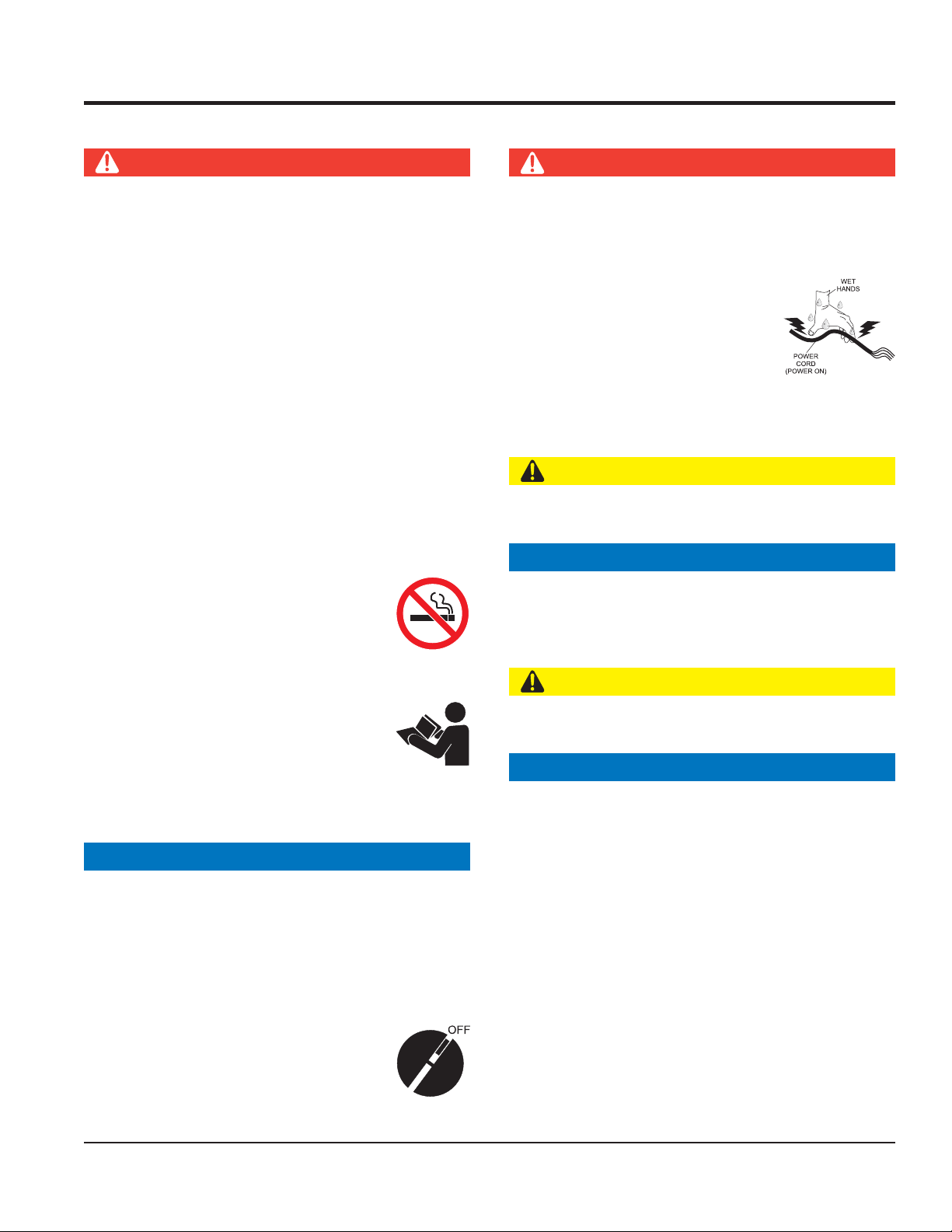
Power Cord/Cable Safety
DANGER
NEVER let power cords or cables lay in water.
NEVER use damaged or worn cables or cords when
connecting equipment to generator. Inspect for cuts in
the insulation.
NEVER grab or touch a live power
cord or cable with wet hands. The
possibility exists of electrical shock,
electrocution or death.
Make sure power cables are securely connected.
Incorrect connections may cause electrical shock and
damage to the mixer.
CAUTION
Ensure that cables and cords will not be tripped over or
trapped underneath the mixer.
NOTICE
DO NOT smoke around or near the
equipment. Fire or explosion could result
from fuel vapors or if fuel is spilled on a
hot engine.
GENERATOR SAFETY
If using a generator to power mixer, refer to
applicable generator manual safety information
section.
ELECTRIC MOTOR SAFETY
(ELECTRIC MODELS ONLY)
NOTICE
Operate electric motor only at the specifi ed voltage
indicated on the nameplate.
DO NOT spray water onto electric motor.
ALWAYS disconnect AC power plug from power source
before moving mixer.
ALWAYS make sure the ON/OFF switch
on the electric motor is in the OFF position
when not in use and before inserting the
mixer’s power plug into an AC receptacle.
ALWAYS make certain that proper power or extension
cord has been selected for the job.
TRANSPORTING SAFETY
CAUTION
NEVER allow any person or animal to stand underneath
the equipment while lifting.
NOTICE
ALWAYS make sure forklift forks are inserted into pockets
(if applicable) as far as possible when lifting the mixer.
ALWAYS shutdown engine before transporting.
NEVER lift the equipment while the engine is running.
Tighten fuel tank cap securely and close fuel cock to
prevent fuel from spilling.
DO NOT lift machine to unnecessary heights.
ALWAYS tie down equipment during transport by
securing the equipment with rope.
NEVER tip the engine to extreme angles during lifting as
it may cause oil to gravitate into the cylinder head, making
the engine start diffi cult.
C10SH8-PH8 CONCRETE MIXER • OPERATION AND PARTS MANUAL — REV. #0 (03/06/09) — PAGE 9
Page 10

SAFETY INFORMATION
TOWING SAFETY
CAUTION
Check with your local county or state safety towing
regulations, in addition to meeting Department of
Transportation (DOT) Safety Towing Regulations,
before towing your mixer.
In order to reduce the possibility of an accident while
transporting the mixer on public roads, ALWAYS make
sure the towing vehicle is mechanically sound and in
good operating condition.
ALWAYS shutdown engine before transporting.
ALWAYS inspect the hitch and coupling for wear. NEVER
tow a mixer with defective hitches, couplings, chains, etc.
Check the tire air pressure on both towing vehicle and
mixer Mixer tires should be infl ated to 50 psi cold. Also
check the tire tread wear on the vehicle and mixer.
ALWAYS make sure the mixer is equipped with a safety
chain.
ENVIRONMENTAL SAFETY
NOTICE
Dispose of hazardous waste properly.
Examples of potentially hazardous waste
are used motor oil, fuel and fuel fi lters.
DO NOT use food or plastic containers to dispose of
hazardous waste.
DO NOT pour waste, oil or fuel directly onto the ground,
down a drain or into any water source.
ALWAYS properly attach mixer’s safety chains to towing
vehicle.
The maximum speed for highway towing is 55 MPH unless
posted otherwise. Recommended off-road towing is not to
exceed 15 MPH or less depending on type of terrain.
Avoid sudden stops and starts. This can cause skidding,
or jack-knifi ng. Smooth, gradual starts and stops will
improve towing.
Avoid sharp turns to prevent rolling.
Mixer should be adjusted to a level position at all times
when towing.
Raise and lock mixer wheel stand in up position when
towing.
Place chock blocks underneath wheel to prevent rolling
while parked.
PAGE 10 — C10SH8-PH8 CONCRETE MIXER • OPERATION AND PARTS MANUAL — REV. #0 (03/06/09)
Page 11

NOTES
C10SH8-PH8 CONCRETE MIXER • OPERATION AND PARTS MANUAL — REV. #0 (03/06/09) — PAGE 11
Page 12
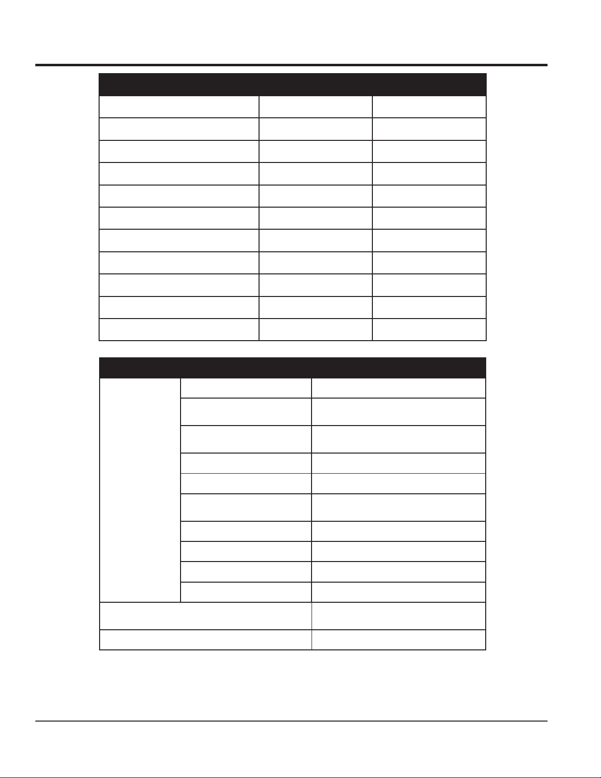
SPECIFICATIONS
Mixer Specifi cationsTable 1.
Model C10SH8 C10PH8
Drum Material Steel Polyethylene
Bag Capacity 1 1
Drum Capacity — cu.ft. (liters) 9.0 (255) 9.0 (255)
Discharge Height — in. cm. 21.5 (55) 21.5 (55)
Drum Opening — in. cm. 20.0 (51) 19.2 (49)
Drum Depth — in. cm 29 (74) 28 (71)
Tires B78 x 13 B78 x 13
Drive V-Belt V-Belt
Dump Action Manual Manual
Weight - With Engine 600 lbs. (272 Kg.) 620 lbs. (281 Kg.)
Engine Specifi cationsTable 2.
Model HONDA GX240U1QA2
Type
Bore X Stroke
Displacement 14.81 cc
Engine
Dimension
(L x W x H)
Dry Net Weight 55.1 lbs (25 Kg.)
Max Output 8.0 H.P./3600 R.P.M.
Fuel Tank Capacity
Fuel Unleaded Gasoline
Lube Oil Capacity 2-1/3 pints
Speed Control Method Centrifugal Fly-weight Type
Starting Method Recoil Start
Air-cooled 4 stroke, Single Cylinder, OHV,
Horizontal Shaft Gasoline Engine
2.90 in. X 2.30 in.
(73 mm x 58 mm)
Approx. 1.59 U.S. Gallons
(6 Liters)
14.0 x 16.9 X 16.1 in.
(355 X 430 X 410 mm)
PAGE 12 — C10SH8-PH8 CONCRETE MIXER • OPERATION AND PARTS MANUAL — REV. #0 (03/06/09)
Page 13
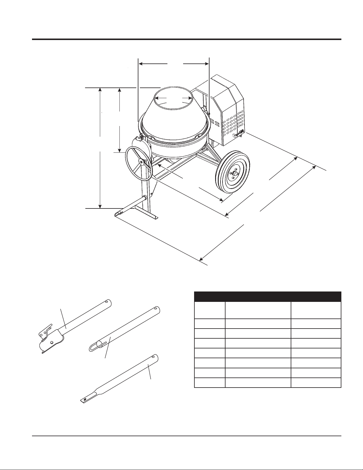
A
DIMENSIONS
C
D
B
OPTIONAL TOW BARS
HBC-1
2-INCH
BALL COUPLER
HLC-1
LOOP COUPLER
HPC-1
1-INCH
PIN COUPLER
E
Reference
F
G
DimensionsTable 3.
Letter
A Height 61 in. (1545 mm)
B Drum height 30 in. (765 mm)
C Drum width 38.6 in. (980 mm)
D Drum neck diameter 21.1 in. (535 mm)
E Width 45.7 in. (1160 mm)
F Length, no tow bar 74.5 in. (1892 mm)
G Length with tow bar 92.7 in. (2355 mm)
Description Dimension
DimensionsFigure 1.
C10SH8-PH8 CONCRETE MIXER • OPERATION AND PARTS MANUAL — REV. #0 (03/06/09) — PAGE 13
Page 14
GENERAL INFORMATION
APPLICATION
This mixer is only intended for the production of concrete.
The mixer must be used for its intended purpose and
is not suitable for the mixing of fl ammable or explosive
substances. The mixer must not be used in an explosive
atmosphere. Use Table 5 (Mixing Hints) as a guide when
mixing concrete for various applications.
POWER PLANTS
The Stow C10SH8 and C10PH8 mixers are powered by an
air-cooled, 4-stroke Honda GX240U1QA2 gasoline engine.
Refer to Table 2 for engine specifi cations.
HARDWARE
Check all hardware on the mixer before starting Periodically
inspect all hardware. Loose hardware can contribute to
early component failure and poor performance. Use Table
4 as general guideline when the torqueing of mixer
hardware is required. Remember to keep all mixer hardware
components tight.
ENGINE MAINTENANCE
For basic engine maintenance, refer to the engine
maintenance section in this manual. For more detailed
engine maintenance information, refer to the Honda engine
owner’s manual supplied with the engine.
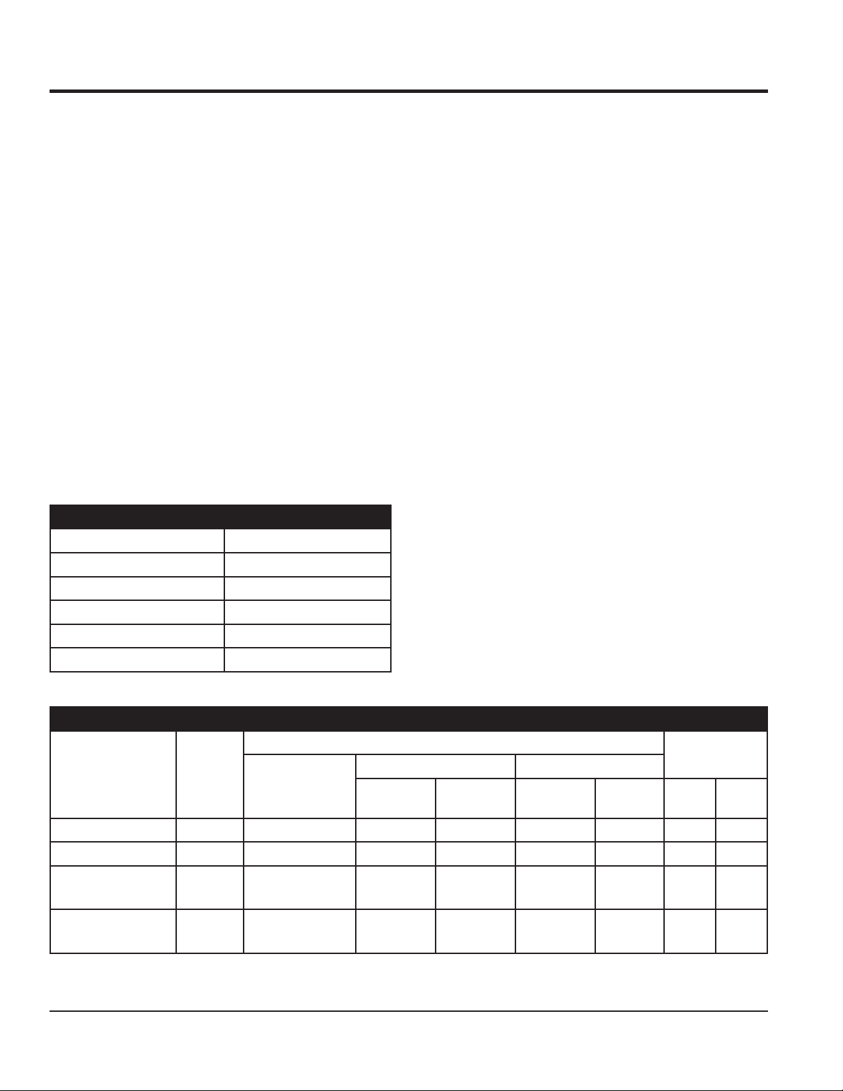
Hardware Torque RecommendationsTable 4.
Hardware Diameter Torque (ft-lbs)
5/16-inch x 18 14
3/8-inch x 16 24
3/8-inch x 24 37
1/2-inch x 13 39
1/2-inch x 13 (Grade 8) 90
Applications
Most Ordinary
Foundations
Rough Mass
Concrete
Mix
Ratios
1:2:4 1/2 Bag 1-1/4 35 2-1/2 71 3 85
1:3:6 1/3 Bag 1-1/4 35 2-1/2 71 2-3/4 78
1:4:8 1/4 Bag 1-1/4 35 2-1/2 71 2-3/4 78
Cement 112
lbs. (50 Kgs.)
Bag
Mixing HintsTable 5.
Batch Quantities
Sand Stone
Cu. Ft. Ltr Cu. Ft. Ltr Cu.Ft. Ltr
Approx. Batch
Output
Watertight Floors,
Tanks, Pits, Etc.
PAGE 14 — C10SH8-PH8 CONCRETE MIXER • OPERATION AND PARTS MANUAL — REV. #0 (03/06/09)
1:1-1/2:3 2/3 Bag 1-1/4 35 3 71 3 85
Page 15
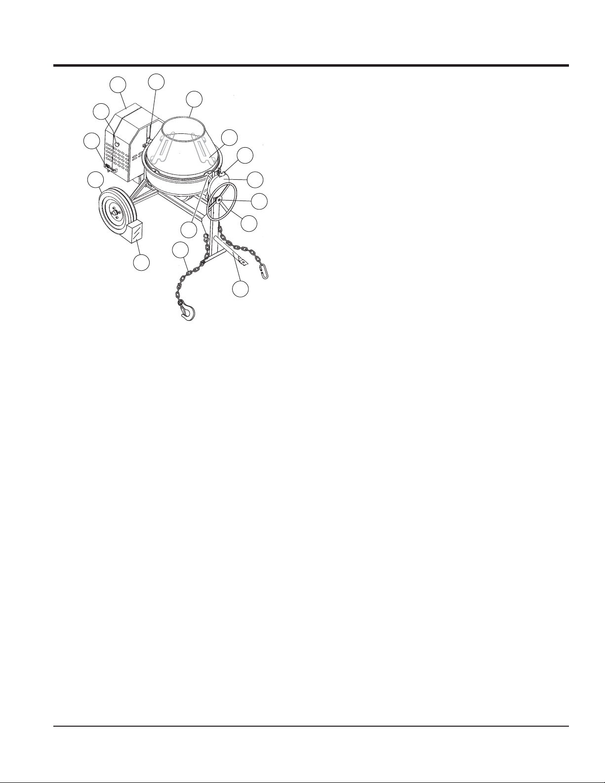
COMPONENTS
11
6
5
4
3
2
6
6
12
Major ComponentsFigure 2.
1
13
7
8
9
10
Figures 2 shows the location of the controls and components
for the C10SH8-PH8 mixer. The function of each control is
described below.
Handwheel 1. — Turn this wheel clockwise or counter-
clockwise to rotate the mixing drum. Remember the
dump latch must be in the up position in order for the
mixing drum to be rotated.
Dump Gear Guard 2. — NEVER operate the mixer with
this guard removed. Its purpose is to prevent dirt and
debris from entering the dump gear. In addition operator
clothing could become entangled in the dump gear,
causing severe injury and bodily harm.
Dump Latch 3. — To rotate the mixing drum, this latch
must be in the up position. To lock the drum, place the
latch in the down position.
Mixing Drum 5. — The C10SH8 uses a 6 cu. ft steel
mixing drum and the C10PH8 uses a 6 cu. ft. plastic
mixing drum. This drum is to be used for mixing of
concrete. Always clean the drum after each use. DO
NOT use this mixing drum for the mixing of volatile
liquids.
Zerk Fittings 6. — There are three zerk fi ttings on the
mixer that lubricate the handwheel, gear and yoke.
Lubricate fi ttings as referenced in the maintenance
section of this manual.
Engine Cabinet 7. — Encloses engine. NEVER run mixer
with cabinet removed.
ON/OFF Switch 8. — This switch is located on the side
of the mixer frame. When activated it will shut down the
engine. Pull out when starting the engine.
Cabinet Latch 9. — Use latches to secure engine
cabinet.
Tire Ply 10. — The tire ply (layers) number is rated in
letters; This mixer uses 13-inch 2-ply tires. Replace
with only recommended type tires.
Chock Blocks 11. — Place these blocks (not included as
part of the mixer package) under each mixer wheel
to prevent rolling when mixer is not connected to the
towing vehicle.
Safety Chain 12. — This mixer uses a 3/16-inch thick,
72-inches long zinc-plated saftey chain. ALWAYS
connect the safety chain when towing.
Tow Bar 13. — This mixer uses various towing bars. Please
reference the frame assembly drawing and parts list
in this manual to determine which tow bar meets your
requirements
Mixing Blades (Steel or Plastic) 4. — Used for the
mixing of concrete. Replace plastic blades when they
show signs of wear. When steel blades show signs
of wear, entire steel mixing drum assembly must be
replaced. See steel and plastic mixing drum assemblies
in the parts section of this manual.
C10SH8-PH8 CONCRETE MIXER • OPERATION AND PARTS MANUAL — REV. #0 (03/06/09) — PAGE 15
Page 16

Engine Components (Honda GX Figure 3.
Series Engine Shown)
The engine (Figure 3) must be checked for proper
lubrication and fi lled with fuel prior to operation. Refer to the
manufacturer’s engine manual for instructions and details
of operation and servicing.
Fuel Filler Cap 1. — Remove this cap to add unleaded
gasoline to the fuel tank. Make sure cap is tightened
securely. DO NOT over fi ll.
BASIC ENGINE
Fuel Valve Lever 5. — OPEN to let fuel fl ow, CLOSE to
stop the fl ow of fuel.
Choke Lever 6. — Used in the starting of a cold engine,
or in cold weather conditions. The choke enriches the
fuel mixture.
Air Cleaner 7. — Prevents dirt and other debris from
entering the fuel system. Remove wing-nut on top of
air fi lter cannister to gain access to fi lter element.
NOTICE
Operating the engine without an air fi lter, with a damaged
air fi lter, or a fi lter in need of replacement will allow dirt to
enter the engine, causing rapid engine wear.
Spark Plug 8. — Provides spark to the ignition system.
Set spark plug gap to 0.6 - 0.7 mm (0.028 - 0.031 inch).
Clean spark plug once a week.
Muffl er 9. — Used to reduce noise and emissions.
WARNING
Engine components can generate extreme
heat. To prevent burns, DO NOT touch
these areas while the engine is running or
immediately after operating. NEVER operate
the engine with the muffl er removed.
DANGER
Adding fuel to the tank should be
accomplished only when the engine is
stopped and has had an opportunity to
cool down. In the event of a fuel spill, DO
NOT attempt to start the engine until the
fuel residue has been completely wiped up, and the
area surrounding the engine is dry.
Throttle Lever 2. — Used to adjust engine RPM speed
(lever advanced forward SLOW, lever back toward
operator FAST).
Engine ON/OFF Switch 3. — ON position permits engine
starting. OFF position stops engine operations.
Recoil Starter (pull rope) 4. — Manual-starting method.
Pull the starter grip until resistance is felt, then pull
briskly and smoothly.
PAGE 16 — C10SH8-PH8 CONCRETE MIXER • OPERATION AND PARTS MANUAL — REV. #0 (03/06/09)
Fuel Tank 10. — Holds unleaded gasoline. For additional
information refer to engine owner’s manual.
Page 17

TOWING GUIDELINES
TOWING SAFETY PRECAUTIONS
CAUTION
Check with your county or state safety towing regulations
department before towing your mixer.
To reduce the possibility of an accident while transporting
the mixer on public roads, always make sure that the
mixer towing components and the towing vehicle are in
good operating condition and both units are mechanically
sound.
The following list of suggestions should be used when
towing the mixer:
Make sure that the hitch and coupling of the towing
vehicle are rated equal to, or greater than the trailer
"gross vehicle weight rating" (GVWR).
ALWAYS inspect the hitch and coupling for wear. NEVER
tow the mixer with defective hitches, couplings, chains
etc.
CHECK the tire air pressure on both the towing vehicle
and the trailer. Also check the tire tread wear on both
vehicles.
ALWAYS make sure the mixer is equipped with a "Safety
Chain".
ALWAYS attach trailer's safety chain to the frame of
towing vehicle.
ALWAYS make sure that the towing vehicle's directional,
backup, and brake lights are working properly.
Remember in most cases the maximum speed unless
otherwise posted for highway towing is 45 MPH, however
before towing your mixer, check your local state, and
county vehicle towing requirements. Recommended offroad towing is not to exceed 10 MPH or less depending
on type of terrain.
Place chocked blocks underneath wheels to prevent
rolling, while parked, if disconnected from towing
vehicle.
Inflate tires to correct pressure, inspect tires for
cuts, and excessive wear. See Table 16 (Tire Wear
Troubleshooting).
When towing of the mixer is required, place the drum in
the up position (mouth facing upwards).
ALWAYS make sure that the fuel valve lever is in the OFF
position (gasoline models only).
Check wheel mounting lug nuts with a torque wrench.
Torque wheel lug nuts as described in the maintenance
section of this manual.
Check tightness of U-clamp nuts, torque suspension
hardware as referenced in the maintenance section of
this manual.
Avoid sudden stops and starts. This can cause skidding,
or jackknifi ng. Smooth, gradual starts and stops will
improve gas milage.
Avoid sharp turns to prevent rolling.
CAUTION
If the mixer tow bar is deformed or damaged replace
entire tow bar. NEVER tow the mixer with a defective tow
bar. There exist the possibility of the trailer separating
from the towing vehicle.
Tow Bar to Vehicle Connection (Coupler Only)
Check the vehicle hitch ball, and mixer's coupler for 1.
signs of wear or damage. Replace any parts that are
worn or damaged before towing.
Use only a 2-inch ball diameter (towing vehicle), this will 2.
match the mixer's 2-inch coupler. Use of any other ball
diameter will create an extremely dangerous condition
which can result in separation of the coupler and ball
or ball failure.
After tow bar has been connected to mixer (see next 3.
page), attach mixer's coupler to the hitch ball on the
towing vehicle securely and make sure the lock lever
is in the down position (locked).
Mixer Tow Bar Vehicle Connection (Pintle and Loop)
Make sure the bumper on the towing vehicle is 1.
equipped to handle either a pintle or loop type tow bar
confi guration.
After tow bar has been connected to mixer (see next 2.
page), secure either type of tow bar to the towing vehicle,
following state and county towing regulations.
As a minimum, use a 1/2-inch bolt and nylock nut grade 3.
5 when securing either tow bar to the towing vehicle.
C10SH8-PH8 CONCRETE MIXER • OPERATION AND PARTS MANUAL — REV. #0 (03/06/09) — PAGE 17
Page 18

SAFETY CHAIN CONNECTION
CAUTION
NEVER tow the mixer with the safety chain removed.
The safety chain is intended to prevent complete
separation of the mixer from the towing vehicle in the
event of a tow bar failure.
Reference Figure 4 for the installation of the Safety
Chain.
Tow Bar to Mixer Connection
Insert the tow bar through the round opening at the 1.
bottom of the mixer stand.
Align the hole on the tow bar with the hole on the mixer
frame, and insert 1/2-inch bolt through tow bar and
frame. Secure tow bar to frame with 1/2-inch nylock
nut. Tighten to 40 ft.-lbs.
Route the safety chain through the holes just above the 2.
tow bar, located on each side of the mixer stand.
Loop the chain together and place under the tow bar.
Secure the loop with the connector link.
Extend the safety chain along the length of the tow bar, 3.
looping it through the tow bar's connector link. Remove
any excess chain slack.
Connect the free end of (clevis safety hook) the safety 4.
chain to the towing vehicle. Remember, it is critical
that the length of the chain be properly adjusted, to
prevent the draw bar and the front of the mixer stand
from dropping to the the ground (contact) in the event
the draw bar becomes disconnected from the towing
vehicle.
MIXER
STAND
STEP 1
CONNECTOR LINK
SAFETY CHAIN
CLEVIS SAFETY HOOK
(TOWING VEHICLE)
STEP 4
SAFETY CHAIN
STEP 2
TOW BAR
STEP 3
Tow Bar and Safety Chain InstallationFigure 4.
1/2-INCH BOLT,
GRADE 5
1/2-INCH NYLOCK
NUT, GRADE 5
SAFETY CHAIN
CONNECTOR LINK
PAGE 18 — C10SH8-PH8 CONCRETE MIXER • OPERATION AND PARTS MANUAL — REV. #0 (03/06/09)
Page 19

INSPECTION
BEFORE STARTING
Read safety instructions at the beginning of manual.1.
Clean the mixer, removing dirt and dust, particularly the 2.
engine cooling air inlet, carburetor and air cleaner.
Check the air fi lter for dirt and dust. If air fi lter is dirty, 3.
replace air fi lter with a new one as required.
Check carburetor for external dirt and dust. Clean with 4.
dry compressed air.
Check fastening nuts and bolts for tightness. 5.
ENGINE OIL CHECK
To check the engine oil level, place the mixer on secure 1.
level ground with the engine stopped.
Remove the fi ller dipstick from the engine oil fi ller hole 2.
(Figure 5) and wipe it clean.
Oil TypeTable 6.
Season Temperature Oil Type
Summer 25°C or Higher SAE 10W-30
Spring/Fall 25°C~10°C SAE 10W-30/20
Winter 0°C or Lower SAE 10W-10
FUEL CHECK
DANGER
Motor fuels are highly fl ammable and can
be dangerous if mishandled. DO NOT
smoke while refueling. DO NOT attempt
to refuel the mixer if the engine is hot or
running.
If fuel is low, remove the fuel fi ller cap and fi ll with unleaded
gasoline.
Remove the gasoline cap located on top of fuel tank.1.
Visually inspect to see if fuel level is low. If fuel is low, 2.
replenish with unleaded fuel.
Engine Oil Dipstick (Removal)Figure 5.
Insert and remove the dipstick without screwing it 3.
into the fi ller neck. Check the oil level shown on the
dipstick.
If the engine oil level is low (Figure 6), fi ll to the edge 4.
of the oil fi ller hole with the recommended oil type (Table
6). See Table 2 for the oil capacity of your type engine.
When refueling, be sure to use a strainer for fi ltration. 3.
DO NOT top-off fuel. Wipe up any spilled fuel.
V-BELT CHECK
A worn or damaged V-belt can adversely affect the
performance of the mixer. If a V-belt is defective or worn,
simply replace the V-belt as outlined in the maintenance
section of this manual.
BLADE CHECK
Check for worn blades. If using a steel tub and the blades
are worn, replace the entire tub assembly. Remember the
blades are welded to tub.
If using a plastic tub, replace the blades using the part
numbers referenced in the parts section of this manual.
START/STOP SWITCHES
This mixer has been equipped with a start/stop switches
for both the gasoline and electric motor mixers. These
switches should be tested every time the engine or motor
is started.
GREASE FITTINGS (ZERK)
Check the zerk fittings (Figure 20) as shown in the
Engine Oil Dipstick (Oil Level)Figure 6.
C10SH8-PH8 CONCRETE MIXER • OPERATION AND PARTS MANUAL — REV. #0 (03/06/09) — PAGE 19
maintenance section of this manual. These grease fi ttings
lubricate the handwheel,gear and yoke.
Page 20

OPERATION
STARTING THE ENGINE
The following steps outline the procedure for starting the
engine. Depending on the type of engine employed in the
mixer, the steps may vary slightly.
Move the fuel shut-off lever (Figure 7) to the ON 1.
position.
Fuel Shut-Off LeverFigure 7.
To start a cold engine, move the choke lever (Figure 2.
8) to the CLOSED position.
Turn the engine switch (Figure 10) to the ON position.4.
Engine ON/OFF SwitchFigure 10.
Located at the rear of the mixer frame is the main start/5.
stop button (Figure 11). Pull this button outward to start
the engine.
Choke LeverFigure 8.
Move the throttle lever (Figure 9) away from the slow 3.
position, about 1/3 of the way toward the fast position.
Engine Start/Stop ButtonFigure 11.
Pull the starter grip (Figure 12) lightly until you feel 6.
resistance, then pull briskly. The drum should be
rotating at this time.
Starter GripFigure 12.
Throttle LeverFigure 9.
PAGE 20 — C10SH8-PH8 CONCRETE MIXER • OPERATION AND PARTS MANUAL — REV. #0 (03/06/09)
Page 21

OPERATION
OPERATION
To position the tub, make sure the mixer is placed on 1.
fi rm level ground, then pull up on the dump latch
(Figure 13) and turn the hand wheel until the tub is at
the desired position. Once the tub is at the desired
position, pull down on the dump latch to lock the tub
in position.
PULL UP TO RELEASE
PULL DOWN TO LOCK
HAND
WHEEL
ROTATE TO
POSITION TUB
CAUTION
Placing the shovel all the way inside the drum will cause
the shovel to strike the blades. This condition will make
the shovel rotate, and cound cause injury to personnel.
NEVER place hands inside the mixing drum while it is
rotating (Figure 15).
Filling Mixing Drum IncorrectlyFigure 15.
Mixing Drum PositionFigure 13.
As the drum rotates, use a shovel (Figure 14) to place 2.
the cement mix inside the drum, add water as required.
Be careful to only place the tip of the shovel inside the
drum.
STOPPING THE MIXER
Push the main start/stop switch (Figure 16) inward to 1.
stop the engine.
Start/Stop Button (Stop Position)Figure 16.
Place fuel shut-off lever in the OFF position.2.
Clean drum of all debris and foreign matter.3.
Filling Mixing DrumFigure 14.
C10SH8-PH8 CONCRETE MIXER • OPERATION AND PARTS MANUAL — REV. #0 (03/06/09) — PAGE 21
Page 22

MAINTENANCE (ENGINE)
Use Table 7 as a general maintenance guideline
when servicing your engine. For more detailed engine
maintenance information, refer to the engine owner’s
manual supplied with your engine.
Engine Maintenance Schedule Table 7.
Description (3) Operation Before
Engine Oil
Air Cleaner
All Nuts and
Bolts
Spark Plug
Cooling Fins Check X
Spark Arrester Clean X
Fuel Tank Clean X
Fuel Filter Check X
Idle Speed Check/Adjust X (2)
Valve Clearance Check/Adjust X (2)
Fuel Lines Check Every 2 years (replace if necessary) (2)
Check X
Change X
Check X
Change X (1)
Re-tighten if
Necessary
Check/Clean X
Replace X
X
First Month
or 10 Hrs.
Every 3
Months or 25
Hrs.
Every 6
Months or 50
Hrs.
Every Year or
100 Hrs.
Every 2 Years
or 200 hrs.
(1) Service more frequently when used in DUSTY areas.
(2) These items should be serviced by your service dealer, unless you have the proper tools and are mechanically
profi cient. Refer to the Honda shop manual for service procedures.
(3) For commercial use, log hours of operation to determine proper maintenance intervals.
PAGE 22 — C10SH8-PH8 CONCRETE MIXER • OPERATION AND PARTS MANUAL — REV. #0 (03/06/09)
Page 23

MAINTENANCE (ENGINE)
MAINTENANCE
Perform the scheduled maintenance procedures as defi ned
by Table 7 and below:
DAILY
Thoroughly remove dirt and oil from the engine and
control area. Clean or replace the air cleaner elements
as necessary. Check and retighten all fasteners as
necessary. Check the gearbox for oil leaks. Repair or
replace as needed.
WEEKLY
Remove the fuel fi lter cap and clean the inside of the
fuel tank.
Remove or clean the fi lter at the bottom of the tank.
Remove and clean the spark plug (Figure 17), then adjust
the spark gap to 0.024 ~0.028 inch (0.6~0.7 mm). This unit
has electronic ignition, which requires no adjustment
DANGER
DO NOT use gasoline as a cleaning solvent because
that would create a risk of fi re or explosion.
ENGINE AIR CLEANER
Remove the air cleaner cover and foam fi lter element 1.
as shown in Figure 19.
Tap the paper fi lter element (Figure 19) several times 2.
on a hard surface to remove dirt, or blow compressed
air [not exceeding 30 psi (207 kPa, 2.1 kgf/cm2)]
through the fi lter element from the air cleaner case
side. NEVER brush off dirt. Brushing will force dirt
into the fi bers. Replace the paper fi lter element if it is
excessively dirty.
Clean foam element in warm, soapy water or 3.
nonfl ammable solvent. Rinse and dry thoroughly. Dip
the element in clean engine oil and completely squeeze
out the excess oil from the element before installing.
Spark GapFigure 17.
ENGINE OIL
Drain the engine oil when the oil is 1. warm as shown
in Figure 18.
Remove the oil drain bolt and sealing washer and allow 2.
the oil to drain into a suitable container.
Replace engine oil with recommended type oil as listed 3.
in Table 6. For engine oil capacity, see Table 2 (engine
specifi cations). DO NOT overfi ll.
Install drain bolt with sealing washer and tighten 4.
securely.
Engine Air CleanerFigure 19.
Engine Oil (Draining)Figure 18.
C10SH8-PH8 CONCRETE MIXER • OPERATION AND PARTS MANUAL — REV. #0 (03/06/09) — PAGE 23
Page 24

MAINTENANCE (MIXER)
BALL SOCKET AND CLAMP FACE
If the towing vechicle is equipped with a ball socket, 1.
smear socket periodically with multi-purpose grease.
This will keep the ball socket well lubricated.
Periodically oil 2. pivot points and clamp face surfaces
of coupler with SAE 30 WT. motor oil.
When parking or storing your mixer. Keep the coupler 3.
off the ground so dirt will not build up in the ball
socket.
GREASE FITTINGS (ZERK)
There are three grease fi ttings (Figure 20) that will require
lubrication. Lubricate these fi ttings once a week. Use
lithium base grease, grade NO. 1.
WHEEL BEARINGS
After every 3 months of operation, remove the hub dust 1.
cap and inspect the wheel bearings (Figure 21). Once
a year, or when required, disassemble the wheel hubs
remove the old grease and repack the bearings forcing
grease between rollers, cone and cage with a good
grade of high speed wheel bearing grease (NEVER
use grease heavier than 265 A.S.T.M. penetration (“No.
2.”)
GREASE
FITTING
AND CAP
Wheel Hub and BearingsFigure 21.
Fill the wheel hub (Figure 21) with grease to the inside 2.
diameter of the outer races and also fi ll the hub grease
cap. Reassemble the hub and mount the wheel. Then
tighten the adjusting nut, at the same time turn the
wheel in both directions, until there is a slight bind to
be sure all the bearing surfaces are in contact.
Then back-off the adjusting nut 1/6 to 1/4 turn or to the
nearest locking hole or suffi ciently to allow the wheel
to rotate freely within limits of .001" to .010" end play.
Lock the nut at this position. Install the cotter pin and
dust cap, and tighten all hardware.
Grease FittingsFigure 20.
MIXER CLEANING
For thorough mix and longer drum life, always wash 1.
drum out after each use.
NEVER2. pour or spray water over the engine.
PAGE 24 — C10SH8-PH8 CONCRETE MIXER • OPERATION AND PARTS MANUAL — REV. #0 (03/06/09)
Page 25

MAINTENANCE (MIXER)
TIRES/WHEELS/LUG NUTS
Tires and wheels are a very important and critical
components of the trailer. When specifying or replacing the
trailer wheels it is important the wheels, tires, and axle are
properly matched.
CAUTION
DO NOT attempt to repair or modify a wheel.
DO NOT install an inter-tube to correct a
leak through the rim. If the rim is cracked,
the air pressure in the inter-tube may cause
pieces of the rim to explode (break-off) with great force
and can cause serious eye or bodily injury.
TIRES WEAR/INFLATION
Tire infl ation pressure is the most important factor in tire
life. Pressure should be checked cold before operation. DO
NOT bleed air from tires when they are hot. Check infl ation
pressure weekly during use to insure the maximum tire life
and tread wear.
Table 8 (Tire Wear Troubleshooting) will help pinpoint the
causes and solutions of tire wear problems.
Tire Wear TroubleshootingTable 8.
Wear Pattern Cause Solution
Center
Wear
Edge
Wear
Side
Wear
Toe
Wear
Cupping
Flat
Spots
Over Infl ation
Under
Infl ation
Loss of
chamber or
overloading
Incorrect
toe-in
Out of
balance
Wheel lockup
and tire
skidding
Adjust pressure to
particular load per
tire manufacturer
Adjust pressure to
particular load per
tire manufacturer.
Make sure load does
not exceed axle
rating. Align wheels.
Align wheels.
Check bearing
adjustment and
balance tires.
Avoid sudden stops
when possible and
adjust brakes.
CAUTION
ALWAYS wear safety glasses when removing
or installing force fitted parts. Failure to
comply may result in serious injury.
C10SH8-PH8 CONCRETE MIXER • OPERATION AND PARTS MANUAL — REV. #0 (03/06/09) — PAGE 25
Page 26

MAINTENANCE (MIXER)
Lug Nut Torque Requirements
It is extremely important to apply and maintain proper wheel
mounting torque on the trailer. Be sure to use only the
fasteners matched to the cone angle of the wheel. Proper
procedure for attachment of the wheels is as follows:
Start all wheel lug nuts by hand.1.
Torque all lug nuts in sequence. See Figure 22. 2. DO
NOT torque the wheel lug nuts all the way down.
Tighten each lug nut in 3 separate passes as defi ned
by Table 9.
After fi rst road use, retorque all lug nuts in sequence. 3.
Check all wheel lug nuts periodically.
Tire Torque RequirementsTable 9.
Wheel Size
12" 20-25 35-40 50-65
13" 20-25 35-40 50-65
14" 20-25 50-60 90-120
15" 20-25 50-60 90-120
16" 20-25 50-60 90-120
First Pass
FT-LBS
Second Pass
FT-LBS
Third Pass
FT-LBS
Wheel Lug Nuts Tightening Figure 22.
Sequence
MIXER STORAGE
For storage of the mixer for over 30 days, the following is
recommended:
Drain the fuel tank completely, or add STA-BIL to the
fuel.
Run the engine until the fuel is completely consumed.
Completely drain used oil from the engine crankcase
and fi ll with fresh clean oil, then follow the procedures
described in the engine manual for engine storage.
Clean the entire mixer and engine compartment.
Place the mixing drum in the down position (mouth facing
downward).
Cover the mixer and place it a clean dry area, that is
protected from harsh elements.
PAGE 26 — C10SH8-PH8 CONCRETE MIXER • OPERATION AND PARTS MANUAL — REV. #0 (03/06/09)
Page 27

NOTES
C10SH8-PH8 CONCRETE MIXER • OPERATION AND PARTS MANUAL — REV. #0 (03/06/09) — PAGE 27
Page 28

TROUBLESHOOTING (ENGINE)
Practically all breakdowns can be prevented by proper
handling and maintenance inspections, but in the event of
a breakdown, please take a remedial action following the
diagnosis based on the Troubleshooting (Tables 10 and 11)
Engine TroubleshootingTable 10.
Symptom Possible Problem Solution
Diffi cult to start
Ignition plug being bridge? Check ignition system.
Fuel is available but spark plug will not
ignite (power available at high tension
cable).
Fuel is available but spark plug will not
ignite (power NOT available at high
tension cable).
Fuel is available and spark plug ignites
(compression normal).
Fuel is available and spark plug ignites
(compression low).
Operation not satisfactory
Not enough power available
(compression normal, no miss-fi ring).
Not enough power available
(compression normal, miss-fi ring).
Rotational speed fl uctuates.
Recoil starter not working properly.
Carbon deposit at ignition? Clean or replace ignition.
Short circuit due to defective insulators? Replace insulators.
Improper spark gap? Set spark plug gap to the correct gap.
Short circuit at stop switch?
Ignition coil defective? Replace ignition coil.
Muffl er clogged with carbon deposits? Clean or replace muffl er.
Fuel in use inadequate (water, dust)?
Air cleaner clogged? Clean or replace air cleaner.
Defective cylinder head gasket?
Cylinder worn? Replace cylinder.
Spark plug loose? Tighten spark plug.
Air cleaner clogged?
Air in fuel line? Bleed (remove air) from fuel line.
Fuel level in carburetor fl oat chamber
improper?
Carbon deposits in cylinder? Clean or replace cylinder.
Ignition coil defective?
Ignition plug often shorts? Replace ignition wires, clean ignition.
Fuel in use inadequate (water, dust)?
Governor adjustment improper? Adjust governor to correct level.
Governor spring defective? Clean or replace ignition.
Fuel fl ow erratic? Check fuel line.
Air taken in through suction line? Check suction line.
Dust in rotating part? Clean recoil starter assembly.
Spring failure? Replace spiral spring.
information shown below and on the next page. If the problem
cannot be remedied, please leave the unit just as it is and
consult our company’s business offi ce or service plant.
Check stop switch circuit. Replace stop
switch if defective.
Flush fuel system and replace with fresh
fuel.
Tighten cylinder head bolts or replace
head gasket.
Adjust carburetor fl oat.
Flush fuel system and replace with fresh
fuel.
Flush fuel system and replace with fresh
fuel.
PAGE 28 — C10SH8-PH8 CONCRETE MIXER • OPERATION AND PARTS MANUAL — REV. #0 (03/06/09)
Page 29

Symptom Possible Problem Solution
Drum rotates rough.
Drum does not rotate at all.
TROUBLESHOOTING (MIXER)
Mixer TroubleshootingTable 11.
Defective ring gear?
Defective pinion gear?
Worn V-belt? Replace V-belt.
Loose pulley? Tighten or replace pulley.
Fuel?
Broken V-belt? Replace V-belt.
Defective ring or pinion gears?
Check that the ring gear and bearings
are not worn. Replace as necessary.
Check that the pinion gear and bearings
are not worn. Replace as necessary.
Check level of fuel in fuel tank. Add fuel
if necessary. Make sure fuel is being
supplied to engine. Check to ensure that
the fuel fi lter is not clogged.
Check that the gears and bearings are
not broken. Replace as necessary.
C10SH8-PH8 CONCRETE MIXER • OPERATION AND PARTS MANUAL — REV. #0 (03/06/09) — PAGE 29
Page 30

EXPLANATION OF CODE IN REMARKS COLUMN
The following section explains the different symbols and
remarks used in the Parts section of this manual. Use the
help numbers found on the back page of the manual if there
are any questions.
NOTICE
The contents and part numbers listed in the parts
section are subject to change without notice. Multiquip
does not guarantee the availability of the parts listed.
SAMPLE PARTS LIST
NO. PART NO. PART NAME QTY. REMARKS
1 12345 BOLT ......................1 .....INCLUDES ITEMS W/%
2% WASHER, 1/4 IN. ...........NOT SOLD SEPARATELY
2% 12347 WASHER, 3/8 IN. ...1 .....MQ-45T ONLY
3 12348 HOSE ..................A/R ...MAKE LOCALLY
4 12349 BEARING ..............1 .....S/N 2345B AND ABOVE
NO. Column
Unique Symbols — All items with same unique
symbol
QTY. Column
Numbers Used — Item quantity can be indicated by a
number, a blank entry, or A/R.
A/R (As Required) is generally used for hoses or other
parts that are sold in bulk and cut to length.
A blank entry generally indicates that the item is not sold
separately. Other entries will be clarifi ed in the “Remarks”
Column.
REMARKS Column
Some of the most common notes found in the “Remarks”
Column are listed below. Other additional notes needed
to describe the item can also be shown.
Assembly/Kit — All items on the parts list with the
same unique symbol will be included when this item is
purchased.
Indicated by:
“INCLUDES ITEMS W/(unique symbol)”
(@, #, +, %, or >) in the number column belong to the
same assembly or kit, which is indicated by a note in the
“Remarks” column.
Duplicate Item Numbers — Duplicate numbers indicate
multiple part numbers, which are in effect for the same
general item, such as different size saw blade guards in
use or a part that has been updated on newer versions
of the same machine.
NOTICE
When ordering a part that has more than one item
number listed, check the remarks column for help in
determining the proper part to order.
PART NO. Column
Numbers Used — Part numbers can be indicated by a
number, a blank entry, or TBD.
TBD (To Be Determined) is generally used to show a
part that has not been assigned a formal part number
at the time of publication.
A blank entry generally indicates that the item is not sold
separately or is not sold by Multiquip. Other entries will
be clarifi ed in the “Remarks” Column.
Serial Number Break — Used to list an effective serial
number range where a particular part is used.
Indicated by:
“S/N XXXXX AND BELOW”
“S/N XXXX AND ABOVE”
“S/N XXXX TO S/N XXX”
Specifi c Model Number Use — Indicates that the part
is used only with the specifi c model number or model
number variant listed. It can also be used to show a
part is NOT used on a specifi c model or model number
variant.
Indicated by:
“XXXXX ONLY”
“NOT USED ON XXXX”
“Make/Obtain Locally” — Indicates that the part can
be purchased at any hardware shop or made out of
available items. Examples include battery cables, shims,
and certain washers and nuts.
“Not Sold Separately” — Indicates that an item cannot
be purchased as a separate item and is either part of an
assembly/kit that can be purchased, or is not available
for sale through Multiquip.
PAGE 30 — C10SH8-PH8 CONCRETE MIXER • OPERATION AND PARTS MANUAL — REV. #0 (03/06/09)
Page 31

SUGGESTED SPARE PARTS
C10SH8-PH8 CONCRETE MIXER WITH HONDA GX240U1QA2 ENGINE
1 to 3 units
Qty. P/N Description
2............EM493399 ............ V-BELT
2............29173-001 ............SWITCH, STOP
4............491010 .................. RUBBER LATCH ASSY.
1............EM903026 ............ BEARING CUP
1............EM903063 ............ BEARING CONE
2............492178 ..................BEARING, SHAFT
2............EM914288 ............ OIL SEAL
1............516592 ..................OIL SEAL
4............EM903113 ............ BEARING CONE
4............EM903012 ............ BEARING CUP
2............3469 ......................DUST CAP
3............9807956846 ..........SPARK PLUG
3............17210ZE2505 ....... AIR FILTER 8.0 HP
1............17620ZH7023 ....... CAP, FUEL
1............28462ZEW211 ...... ROPE, 8.0 HP
NOTICE
Part numbers on this Suggested Spare Parts list may
supersede/replace the part numbers shown in the
following parts lists.
C10SH8-PH8 CONCRETE MIXER • OPERATION AND PARTS MANUAL — REV. #0 (03/06/09) — PAGE 31
Page 32

NAMEPLATES AND DECALS
WARNING
CRUSH HAZARD
Keep guards and
doors in place.
Shut-off engine
before inspection
or maintenance
CRUSH AND CUT
HAZARD
Moving parts can cut
2
and crush.
SHUT OFF engine
before putting hands
in mixing drum
DCL160
1
1
3
4
WARNING
SAFETYINSTRUCTIONS
1.Read owner’s manual
before operating.
2.Keep unauthorized and
untrained people away from
machine during operation.
3.Make sure all safety devices
are in place before this
machine is started.
4.Make sure engine is turned
off and spark plug wire is
disconnected before cleaning
the machine.
5.Keep hands and fingers
away from moving objects.
6.Do not operate machine in
an enclosed area,proper
ventilation is required.
7.Never leave machine
unattended when operating.
8.Always stop engine and
allow engine to cool before
adding fuel or oil.
WARNING
Toavoid injury,
you MUST read
and understand
operator’s manual
before using this
machine.
This machine to
be operated by
qualified
personnel only.
Ask for training
as needed.
P/N35137
5
REAR VIEW
WARNING
DCL160
PUSH
TO STOP
CRUSH AND CUT
HAZARD
Moving parts can cut
and crush.
SHUT OFF engine
before putting hands
in mixing drum
ENGINE COVER
CRUSH HAZARD
Keep guards and
2
doors in place.
Shut-off engine
before inspection
or maintenance
6
1
3
7
MODEL
SERIAL NO.
PAGE 32 — C10SH8-PH8 CONCRETE MIXER • OPERATION AND PARTS MANUAL — REV. #0 (03/06/09)
Page 33

NAMEPLATES AND DECALS
NO. PART NO. PART NAME QTY. REMARKS
1 510164 DECAL, STOW A DIVISION OF MULTIQUIP 3
2 DCL160A DECAL, CRUSH WARNING 2
3 DCL151 DECAL, WARNING TOWING 2
4 504713 DECAL, WARNING SAFETY INSTRUCTIONS 1
5 35137 DECAL, READ MANUAL 1
6 EM948630 DECAL, PUSH TO STOP 1
7 NAMEPLATE ............................................................1................CONTACT MQ PARTS DEPT.
C10SH8-PH8 CONCRETE MIXER • OPERATION AND PARTS MANUAL — REV. #0 (03/06/09) — PAGE 33
Page 34

PLASTIC DRUM ASSY
8
5
4
11
10
1
12
4
5
13
14
18
20
25
19
21
24
22
17
8
6
9
4
23
4
3
2
5
7
7
24
26
25
27
YOKE
28
29
PAGE 34 — C10SH8-PH8 CONCRETE MIXER • OPERATION AND PARTS MANUAL — REV. #0 (03/06/09)
Page 35

PLASTIC DRUM ASSY
NO. PART NO. PART NAME QTY. REMARKS
1 516658 GEAR RING 1
2 412379 SCREW, CAP 3/8" 4
3 511729 SHIM 8
4 EM969013 NUT, NYLOC 30
5 510909 WASHER 19
6 510916 DRUM, PLASTIC 1
7 511089 SUPPORT BRACKET 4
8 EM963057 SCREW, CAP 3/8" X 1-1/2" 5
9 3019092 WASHER, 3/8" FLAT 2
10 510884 BLADE, PLASTIC DRUM 3
11 515453 SCREW 3
12 515304 PLATE PROTECTION 2
13 515305 PLATE PROTECTION 4
14 507538C BUSHING 8
17 516424 CAP, PLASTIC DRUM 1
18 516618 O-RING 1
19 516678C NUT, KING PIN 1
20 EM924006 PIN, COTTER 1/8 X 3/4 1
21 517134 WASHER 1
22 516504 PIN, KING 1
23 516706 SUPPORT SPIDER 1
24 EM903026 BEARING CUP 2
25 EM903063 BEARING CONE 2
26 503116 BOLT 3/8" NC X 3-3/8" 1
27 516592 OIL SEAL 1
28 492491 SCREW, SET 1
29 516614 NUT 1
C10SH8-PH8 CONCRETE MIXER • OPERATION AND PARTS MANUAL — REV. #0 (03/06/09) — PAGE 35
Page 36

STEEL DRUM ASSY
7
8
9
10
13
11
14
12
13
14
1
3
2
6
4
5
1
15
YOKE
17
16
NOTES
MIXING BLADES ARE PART OF
DRUM ASSEMBLY. TO RE-ORDER
1
NEW BLADES A COMPLETE MIXING
DRUM MUST BE PURCHASED.
PAGE 36 — C10SH8-PH8 CONCRETE MIXER • OPERATION AND PARTS MANUAL — REV. #0 (03/06/09)
Page 37

STEEL DRUM ASSY
NO. PART NO. PART NAME QTY. REMARKS
1 516658 GEAR RING 1
2 EM963057 SCREW, CAP 3/8" X 1-1/2" 4
3 511730 SHIM 8
4 492542 NUT 4
5 0166 A WASHER, LOCK 3/8" 4
6 516575 DRUM, STEEL 1
7 516511 CAP, DRUM 1
8 516618 O-RING 1
9 516678 NUT, KING PIN 1
10 EM924006 PIN, COTTER 1/8" X 3/4" 1
11 504447 WASHER 1
12 516495 PIN, KING 1
13 EM903063 BEARING CONE 2
14 EM903026 BEARING CUP 2
15 516592 OIL SEAL 1
16 492491 SCREW, SET 1
17 516614 NUT 1
C10SH8-PH8 CONCRETE MIXER • OPERATION AND PARTS MANUAL — REV. #0 (03/06/09) — PAGE 37
Page 38

YOKE ASSY.
1
1
10
9
11
2
3
8
8
4
PART OF
1
5
PART OF
YOKE
1
6
7
FRAME
1
12
NOTES
SEE PLASTIC OR STEEL
DRUM ASSY.
PAGE 38 — C10SH8-PH8 CONCRETE MIXER • OPERATION AND PARTS MANUAL — REV. #0 (03/06/09)
Page 39

YOKE ASSY.
NO. PART NO. PART NAME QTY. REMARKS
1 491008 FITTING PROTECTOR 1
2 EM916001 GREASE FITTING 1
3 500214 KEY SQUARE 1/4" X 1/4" X 1-1/2" 1
4 503915 PINION GEAR 1
5 492468 SCREW, SET 5/16" 1
6 516654 SUPPORT YOKE 1
7 513991 PINION, JACKSHAFT 1
8 492178 BEARING, SHAFT 2
9 EM963692 SCREW, CAP HHCS, 1/2-13 X 1 2
10 490970 SNAP RING 1
11 514036 HOUSING, JACKSHAFT 1
12 492584 NUT, LOCK 1/2" 2
C10SH8-PH8 CONCRETE MIXER • OPERATION AND PARTS MANUAL — REV. #0 (03/06/09) — PAGE 39
Page 40

FRAME ASSY.
7
6
8
5
4
3
2
14
1
7
26
5
9
10
12
11
13
19
17
15
8
24
25
16
A
18
OPTIONAL TOW BARS
A
22
21
CHAIN
20
&
LINK
KIT
23
PAGE 40 — C10SH8-PH8 CONCRETE MIXER • OPERATION AND PARTS MANUAL — REV. #0 (03/06/09)
Page 41

FRAME ASSY.
NO. PART NO. PART NAME QTY. REMARKS
1 514245 GUARD, GEAR WHEEL 1
2 3103160 WASHER 4
3 492278 BOLT HEAD ROUND 1/4 X 3/8 4
4 516668 GEAR, DUMP 1
5 492584 NUT, LOCK 1/2" 3
6 490895 DUMP LATCH 1
7 491008 FITTING PROTECTOR 2
8 EM916001 GREASE FITTING 2
9 492329 BOLT, 1/2" NC X 1-3/4" G2 1
10 492259 BOLT, 5/16" NC X 3/4" 3
11 EM923343 WASHER, LOCK 5/16" 3
12 EM963102 BOLT, HHCS 1/2" NC X 1-1/4" 2
13 516534 HANDWHEEL SHAFT 1
14 501808 HANDWHEEL 1
15 490961 RETAINING RING 1
16 10176 NUT, NYLOC 1/2-13 1
17 EM124 BOLT, HHCS 1/2 X 4 G5 1
18% 516581 CLEVIS SAFETY HOOK 1
19 516560 FRAME 1
20 13363KIT CHAIN AND LINK KIT ........................................1................INCLUDES ITEMS W/%
21 HBC-1 BALL HITCH 1
22 HLC-1 LOOP HITCH 1
23 HPC-1 PIN HITCH 1
24% SAFETY CHAIN 2
25% 01004 CONNECTOR LINK 1
26 504447 WASHER 1
C10SH8-PH8 CONCRETE MIXER • OPERATION AND PARTS MANUAL — REV. #0 (03/06/09) — PAGE 41
Page 42

FRAME
HUB/TIRE ASSY.
4
5
6
7
1
6
5
11
10
9
12
13
8
NOTES:
COMPLETE HUB ASSEMBLY INCLUDES
1
ITEMS WITHIN DASHED LINES AND
ITEMS 13 AND 14.
PAGE 42 — C10SH8-PH8 CONCRETE MIXER • OPERATION AND PARTS MANUAL — REV. #0 (03/06/09)
14
Page 43

HUB/TIRE ASSY.
NO. PART NO. PART NAME QTY. REMARKS
4% EM914288 OIL SEAL 2
5% EM903113 BEARING CONE 4
6% EM903012 BEARING CUP 4
7 EM941306 HUB ASSY, 4-BOLT 2 INCLUDES ITEMS W/%
8% EM511159 WASHER, FLAT, .087" THICKNESS 2
9% EM501299 WASHER, FLAT, .135" THICKNESS A/R
10 491688 COTTER PIN, 1/8" X 1-1/2" 2
11 8164 NUT, SLOTTED HEX JAM 1"-20 2
12 516476 TIRE AND RIM 2
13 8115 LUG NUT 8
14 3469 DUST CAP 2
C10SH8-PH8 CONCRETE MIXER • OPERATION AND PARTS MANUAL — REV. #0 (03/06/09) — PAGE 43
Page 44

CABINET ASSY.
1
4
FRAME
10
11
5
8
9
3
6
2
7
ENGINE
BASE
PLATE
PAGE 44 — C10SH8-PH8 CONCRETE MIXER • OPERATION AND PARTS MANUAL — REV. #0 (03/06/09)
Page 45

CABINET ASSY.
NO. PART NO. PART NAME QTY. REMARKS
1 514052 CABINET 1
2 491010 RUBBER LATCH ASSY. 2
3 1307 SCREW, PHP 8-32 X 1/2 PLATED 6
4 492312 BOLT, 3/8" NC X 1-1/4" G2 2
5 3019092 WASHER, FLAT 3/8" 2
6 501028 SPACER 2
7 EM969013 NUT, NYLOC 3/8" 2
8 492357 BOLT, 1/4" NC X 1" G5 4
9 EM923057 WASHER, 1/4" 4
10 2101402 WASHER, LOCK 1/4" 4
11 2101428 NUT, 1/4-20 4
C10SH8-PH8 CONCRETE MIXER • OPERATION AND PARTS MANUAL — REV. #0 (03/06/09) — PAGE 45
Page 46

ENGINE ASSY.
15
PART OF
CABINET
16
17
10
1
14
2
7
8
3
4
5
14
10
11
6
13
DRIVE
PINION
SHAFT
12
9
FRAME
PAGE 46 — C10SH8-PH8 CONCRETE MIXER • OPERATION AND PARTS MANUAL — REV. #0 (03/06/09)
Page 47

ENGINE ASSY.
NO. PART NO. PART NAME QTY. REMARKS
1 GX240U1QA2 ENGINE, HONDA 8.0 HP 1
2 492378 BOLT, 3/8" NC X 1-3/4" G5 4
3 3019092 WASHER, FLAT 3/8" 4
4 0166 A WASHER, LOCK 3/8" 4
5 1456 NUT, HEX 3/8 - 16 4
6 516648 ENGINE BASE PLATE 1
7 EM963692 BOLT, HHCS 1/2 - 13 X 1-1/2 4
8 EM621 WASHER, 1/2" 4
9 492584 NUT, LOCK 1/2" 4
10 492468 SCREW, SET 5/16" 2
11 504075 PULLEY, SMALL 1
12 EM493399 V-BELT 1
13 514060 PULLEY, LARGE 1
14 500214 KEY, SQUARE 1/4 X 1/4 X 1-1/2 2
15 29174-001 BUTTON, STOP 1
16 29173-001 SWITCH, STOP 1
17 510573C HARNESS, STOP SWITCH 1
C10SH8-PH8 CONCRETE MIXER • OPERATION AND PARTS MANUAL — REV. #0 (03/06/09) — PAGE 47
Page 48

TERMS AND CONDITIONS OF SALE — PARTS
PAYMENT TERMS
Terms of payment for unit sales are 2% 15
days net 30 days from date of invoice unless
otherwise specifi cally stated on our invoice.
Parts invoices have terms of net 10 days.
Minimum parts billing is $15.00 net.
Applicable discounts will be computed on
merchandise value only. Late charges will be
assessed at prevailing rates. Cash discounts
cannot be taken on current billings if any
previously billed amounts are past due.
FREIGHT POLICY
Freight policy is established to offer customers
every advantage possible. Due to bulk freight
ratings on some equipment and other shipping
considerations, freight policies differ by
equipment type. Actual back freight may be
charged for shipments originating from other
than specifi ed FOB warehouses. See Freight
Policy for details.
All STOW domestic sales are FOB nearest
available designated MQ/STOW warehouse.
Export orders are ex-works factory located in
Carson, CA or Boise, ID.
Additions to orders already shipped cannot be
accepted for freight minimums.
Should STOW elect to make partial shipments
of an order originally complying with the
“freight allowed” requirements, transportation
charges will be absorbed by STOW on any
subsequent shipment applying to that order.
All other orders will be shipped collect or
prepaid with charges added to the invoice.
STOW’s responsibility ceases when a signed
manifest has been obtained from the carrier,
and any claim for shortage or damage must
be settled between the consignee and the
carrier.
Parts: FOB Carson, California or Boise, Idaho.
See Freight Policy for details and additional
discounts.
DROP SHIPMENTS
STOW reserves the right to refuse Drop
Shipments outside the normal service area
of the purchasing dealer.
FIELD WAREHOUSES
Field Warehouses are currently located in
California, Georgia, Idaho, Iowa, and New
Jersey
SPECIAL EXPEDITING SERVICE
The higher of a $35.00 surcharge or actual
costs will be added to the invoice for special
handling, including bus shipments, or in cases
where STOW personnel must personally
deliver the equipment or parts to the carrier.
RETURNED GOODS POLICY
Return shipments may be accepted and credit
allowed, subject to the following provisions.
A Returned Material Authorization (RMA) 1.
must be approved by STOW prior to
shipment. Approvals for returned goods
must be with just cause and are at the
sole discretion of STOW. A copy of the
Authorization must accompany the
shipment to the designated Warehouse.
Parts being returned must be listed as 2.
currently supplied on the current parts
list.
Parts must be in new and resalable 3.
condition in the original package, with
part numbers clearly marked.
Units and accessories must be current 4.
models in the latest price list and in new
and resalable condition.
Special order items are not returnable 5.
for credit.
Credit on returned parts and units will be
6.
issued at actual dealer net price at time of
purchase less 15% restocking charge.
All returned shipments are to be made 7.
to the STOW designated receiving point,
freight prepaid at the sender’s expense.
The sender will be notifi ed of any material
received that does not meet the above
provisions. Such material will be held for 30
days from notifi cation pending instructions.
If a reply is not received within 30 days, the
material will be returned to the sender at his
expense with no credit issued.
PRICING, REBATES AND SPECIFICATIONS
Every effort will be made to provide adequate
notice of changes; however, prices and
equipment specifications are subject to
change without notice.
Price changes are effective on a specifi c date
and all orders received on or after that date
will be billed at the revised price.
Rebates for price reductions and added
charges for price increases will not be made
for stock in dealer inventory at the time of a
price change.
STOW reserves the right to quote and sell
direct to Government agencies and to Original
Equipment Manufacturer accounts who use
our products as integral parts of their own
products.
LIMITATION OF SELLER’S LIABILITY
STOW shall not be liable hereunder for
damages in excess of the purchase price
of the item with respect to which damages
are claimed and in no event shall STOW be
liable for loss of profi t or good will or for any
other special, consequential or incidental
damages.
LIMITATION OF WARRANTIES
There are no warranties, express or implied,
made by STOW. hereunder on Products
manufactured or distributed by it except the
warranty against defects in material and
workmanship on new Products to the original
purchaser, as set forth in the STOW New
Product Limited Warranty.
Effective: July 15, 2003
Terms And Conditions Of Sale
STOW Construction Equipment
STOW CONSTRUCTION EQUIPMENT
POST OFFICE BOX 6254
CARSON, CALIFORNIA 90749
310-661-4242 • 877-BUY-STOW
FAX: 310-604-9237
E-MAIL: stow@stowmfg.com
www.stowmfg.com
Atlanta • Boise • Newark • Quebec, Canada
Manchester, UK • Rio de Janeiro, BR • Puebla, MX
PAGE 48 — C10SH8-PH8 CONCRETE MIXER • OPERATION AND PARTS MANUAL — REV. #0 (03/06/09)
Page 49

NOTES
C10SH8-PH8 CONCRETE MIXER • OPERATION AND PARTS MANUAL — REV. #0 (03/06/09) — PAGE 49
Page 50

OPERATION AND PARTS MANUAL
©
HERE’S HOW TO GET HELP
PLEASE HAVE THE MODEL AND SERIAL
NUMBER ON-HAND WHEN CALLING
PARTS DEPARTMENT
800-427-1244 FAX: 800-672-7877
310-537-3700 FAX: 310-637-3284
SERVICE DEPARTMENT
800-478-1244 FAX: 310-537-4259
310-537-3700
TECHNICAL ASSISTANCE
800-478-1244 FAX: 310-631-5032
WARRANTY DEPARTMENT
800-421-1244, EXT. 279 FAX: 310-537-1173
310-537-3700, EXT. 279
SALES DEPARTMENT
310-661-4242 FAX: 310-604-9237
877-289-7869 (877-BUY-STOW)
COPYRIGHT 2009, MULTIQUIP INC.
Multiquip Inc, and the STOW logo are registered trademarks of Multiquip Inc. and may not be used, reproduced, or altered without written permission. All other trademarks are the
property of their respective owners and used with permission.
This manual must accompany the equipment at all times. This manual is considered a permanent part of the equipment and should remain with the unit if resold.
The information and specifi cations included in this publication were in effect at the time of approval for printing. Illustrations, descriptions, references and technical data contained in
this manual are for guidance only and may not be considered as binding. Multiquip Inc. reserves the right to discontinue or change specifi cations, design or the information published
in this publication at any time without notice and without incurring any obligations.
Your Local Dealer is:
Atlanta • Boise • Newark • Quebec, Canada
Manchester, UK • Rio de Janeiro, BR • Puebla, MX
MQ STOW CONSTRUCTION EQUIPMENT
A DIVISION OF MULTIQUIP INC.
POST OFFICE BOX 6254
CARSON, CA 90749
310-537-3700 • 888-252-MQ STOW [888-2527869]
FAX: 310-537-1986 • FAX: 800-556-1986
E-MAIL: MQ STOW@multiquip.com • WWW:
stowmfg.com
 Loading...