

Page 1

PARTS AND OPERATION MANUAL
Table of Contents
PARTS AND OPERATION MANUAL
MQ POWER
TM
DUELWELD
WELDER/AC GENERATOR
MODEL BLW-400SSW
© COPYRIGHT 2001, MULTIQUIP INC.
S/N 5308765~
Revision #1(06/15/01)
MUL TIQUIP INC. PARTS DEPARTMENT:
18910 WILMINGTON AVE. 800-427-1244
CARSON, CALIFORNIA 90746 FAX: 800-672-7877
310-537-3700
800-421-1244 800-835-2551
F AX: 310-537-3927 F AX: 310-638-8046
E-mail:mq@multiquip.com • www:multiquip.com
SERVICE DEPARTMENT:
Page 2
PAGE 2 — BLW-400SSW- WELDER/AC GENERATOR — PARTS & OPERATION MANUAL — REV. #1 (06/15/01)
Table of Contents
Page 3

HERE'S HOW TO GET HELP
Table of Contents
PLEASE HAVE THE MODEL AND SERIAL NUMBER
ON-HAND WHEN CALLING
PARTS DEPARTMENT
800/427-1244 or 310/537-3700
FAX: 800/672-7877 or 310/637-3284
SER VICE DEPARTMENT
800/835-2551 or 310/537-3700
FAX: 310/638-8046
WARRANTY DEPARTMENT
800/835-2551 or 310/537-3700
FAX: 310/638-8046
MAIN
800/421-1244 or 310/537-3700
FAX: 310/537-3927
BLW-400SSW-WELDER/AC GENERATOR— PARTS & OPERATION MANUAL— REV. #1 (06/15/01) — PAGE 3
Page 4

TABLE OF CONTENTS
Here’s How to Get Help........................................... 3
Parts Ordering Procedures ..................................... 5
Rules for Safe Operation ..................................... 6-7
Operation and Safety Decals ............................... 8-9
Specifications ........................................................ 10
General Information.............................................. 11
Dimensions ........................................................... 12
Trailer Safety Guidelines..................................13-18
Trailer Wiring Diagram........................................... 19
Electrical Brake Troubleshooting........................... 20
Towing Safety Guidelines...................................... 2 1
Controls and Indicators.................................... 22-23
Output Terminal Overview................................24-25
Installation............................................................. 26
Pre-Set Up ....................................................... 27-29
Load Application ................................................... 3 0
Welder Operating Instructions ......................... 31-32
Welder/AC Generator Star t-up Instructions ..... 33-34
Shutdown Instructions........................................... 35
Maintenance ......................................................... 36
Preparation for Long Term Storage ...................... 37
Generator Wiring Diagram ............................... 38-39
Engine Wiring Diagrams................................... 40-41
Engine Troubleshooting .................................... 42-44
Welding Troubleshooting ....................................... 4 5
Explanation of Codes in Remarks Section............ 4 6
Suggested Spare Parts List .................................. 4 7
BLW-400SSW WELDER/
AC GENERA TOR
Generator Assembly ........................................ 48-51
Control Box Assembly...................................... 52-55
Control Parts Assembly, par t 1 ........................ 56-57
Control Parts Assembly, par t 2 ........................ 58-59
Engine and Radiator Assembly........................ 60-61
Battery Assembly .............................................62-63
Muffler Assembly ............................................. 64-65
Fuel Tank Assembly ......................................... 66-67
Enclosure Assembly......................................... 68-69
Rubber Seals Assembly................................... 70-71
Decal Assembly ............................................... 72-73
KUBOT A V1205B ENGINE
Crankcase Assembly ....................................... 74-75
Oil Pan Assemb ly ............................................. 76-77
Cylinder Head Assembly..................................78-79
Gear Case Assembly ....................................... 80-81
Main Bearing Case Assembly.......................... 82-83
Head Cover Assembly ..................................... 84-85
Inlet Manifold Assembly ................................... 86-87
Exhaust Manifold Assembly ............................. 88-89
Rocker Arm Valve Assembly ............................ 90-91
Camshaft Assembly ......................................... 92-93
Piston Crankshaft Assembly ............................ 94-95
Flywheel Assembly .......................................... 96-97
Injection Pump Assembly................................. 98-99
Fuel Camshaft Assembly .............................100-101
Nozzle Holder Assembly .............................. 102-103
Idling Apparatus Assembly .......................... 104-105
Governor Assembly ..................................... 106-107
Speed Control Plate Assembly .................... 108-109
Dynamo Assembly ....................................... 110-111
Water Flange Assembly ............................... 112-113
W ater Pump Assembly................................. 114-115
Fan Assembly............................................... 116-117
Radiator Assembly....................................... 118-119
Air Cleaner Assembly................................... 120-121
Fuel Filter Component Assembly................. 122-123
Dynamo Component Assembly ................... 124-125
Star ter Component Assembly ...................... 126-127
Nozzle Holder Component Assembly .......... 128-129
Injection Pump Component Assembly ......... 130-133
Accessories.................................................. 134-135
Terms and Conditions - Sales ............................. 136
NOTE
Specification and part number
are subject to change without
notice.
PAGE 4 — BLW-400SSW- WELDER/AC GENERATOR — PARTS & OPERATION MANUAL — REV. #1 (06/15/01)
Page 5

PARTS ORDERING PR OCEDURES
Table of Contents
■■
■ Dealer account number
■■
■■
■ Dealer name and address
■■
■■
■ Shipping address (if different than billing address)
■■
■■
■ Return fax number
■■
■■
■ Applicable model number
■■
■■
■ Quantity, part number and description of each part
■■
■■
■ Specify preferred method of shipment:
■■
UPS Ground
•
UPS Second Day or Third Day*
•
UPS Next Day*
•
Federal Express Priority One (please provide us with your Federal
•
Express account number)*
Airborne Express*
•
Truck or parcel post
•
*Normally shipped the same day the order is received, if prior to 2PM west coast time.
Earn Extra Discounts when
you order by FAX!
All parts orders which include complete par t numbers
and are received by fax qualify for the following extra
discounts:
Number of
line items ordered Additional Discount
1-9 items 3%
10+ items** 5%
Get special freight allowances
when you order 10 or more
line items via FAX!**
■■
■
UPS Ground Service at no charge for freight
■■
■■
■
PS Third Day Service at one-half of actual freight cost
■■
No other allowances on freight shipped by an y other carrier.
**Common nuts, bolts and washers (all items under $1.00 list price)
do not count towards the 10+ line items.
Extra Fax Discount
for Domestic USA
Dealers Only
UPS
Special
For faxed orders only
Now! Direct TOLL-FREE access
to our Par ts Depar tment!
Toll-free nationwide:
800-421-1244
Toll-free FAX:
*DISCOUNTS ARE SUBJECT TO CHANGE*
Fax order discount and UPS special programs revised June 1, 1995
BLW-400SSW-WELDER/AC GENERATOR— PARTS & OPERATION MANUAL— REV. #1 (06/15/01) — PAGE 5
800/6-PARTS-7 • 800-672-7877
Page 6
RULES FOR SAFE OPERATION
Table of Contents
CAUTION:
■
Failure to f ollow instructions in this manual may
lead to serious injury or even death! This
equipment is to be operated by trained and
qualified personnel only! This equipment is for
industrial use only .
The following safety guidelines should always be used when
operating the BL W-400SSW W elder/AC Generator:
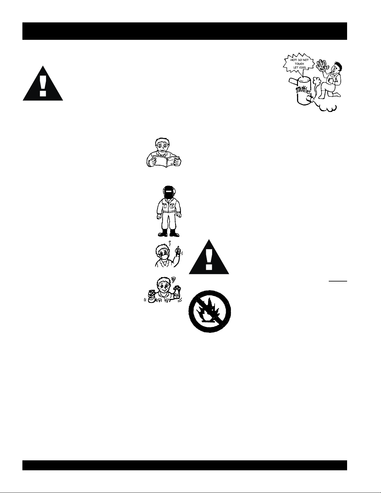
GENERAL SAFETY
■
DO NOT operate or service this equipment before
reading this entire manual.
■
This equipment should not be operated by
persons under 18 years of age.
■
NEVER operate this equipment without proper
protective clothing, welding shield, ventilator,
steel-toed boots and other protective devices
required by the job.
NEVER touch the hot exhaust
manifold, muffler or cylinder. Allow
these parts to cool before servicing
engine or welder/AC generator .
■
High Temperatures – Allow the engine to cool before adding
fuel or performing service and maintenance functions. Contact
hot
with
■
The engine of this welder/AC generator requires an adequate
free flow of cooling air . Ne ver operate the welder/A C generator
in any enclosed or narrow area where free flow of the air is
restricted. If the air flow is restricted it will cause serious damage
to the welder/AC generator engine and may cause injury to
people. The engine gives off DEADLY carbon monoxide gas .
CAUTION
■
NEVER operate this equipment when not feeling
well due to fatigue, illness or taking medicine.
■
NEVER operate this equipment under the
influence or drugs or alcohol.
components can cause serious burns.
:
Always refuel in a well-ventilated area, away
from sparks and open flames.
Always use extreme caution when working with
flammable liquids. When refueling, stop the
engine and allow it to cool. DO NOT
around or near the machine. Fire or
explosion could result from fuel vapors, or if
fuel is spilled on a hot engine.
smoke
■
NEVER use accessories or attachments, which are not
recommended by MQ P ower f or this equipment. Damage to
the equipment and/or injury to user may result.
■
Manufacture does not assume responsibility for any accident
due to equipment modifications.
■
Whenever necessary, replace nameplate, operation and
safety decals when they become difficult read.
■
Always check the machine for loosened threads or bolts before
starting.
PAGE 6 — BLW-400SSW- WELDER/AC GENERATOR — PARTS & OPERATION MANUAL — REV. #1 (06/15/01)
■
NEVER operate the welder/AC
generator in an explosive atmosphere or
near combustible materials. An explosion or
fire could result causing severe
or even death.
■
Topping-off to filler port is dangerous, as it tends to spill fuel.
bodily harm
Page 7
RULES FOR SAFE OPERATION
Table of Contents
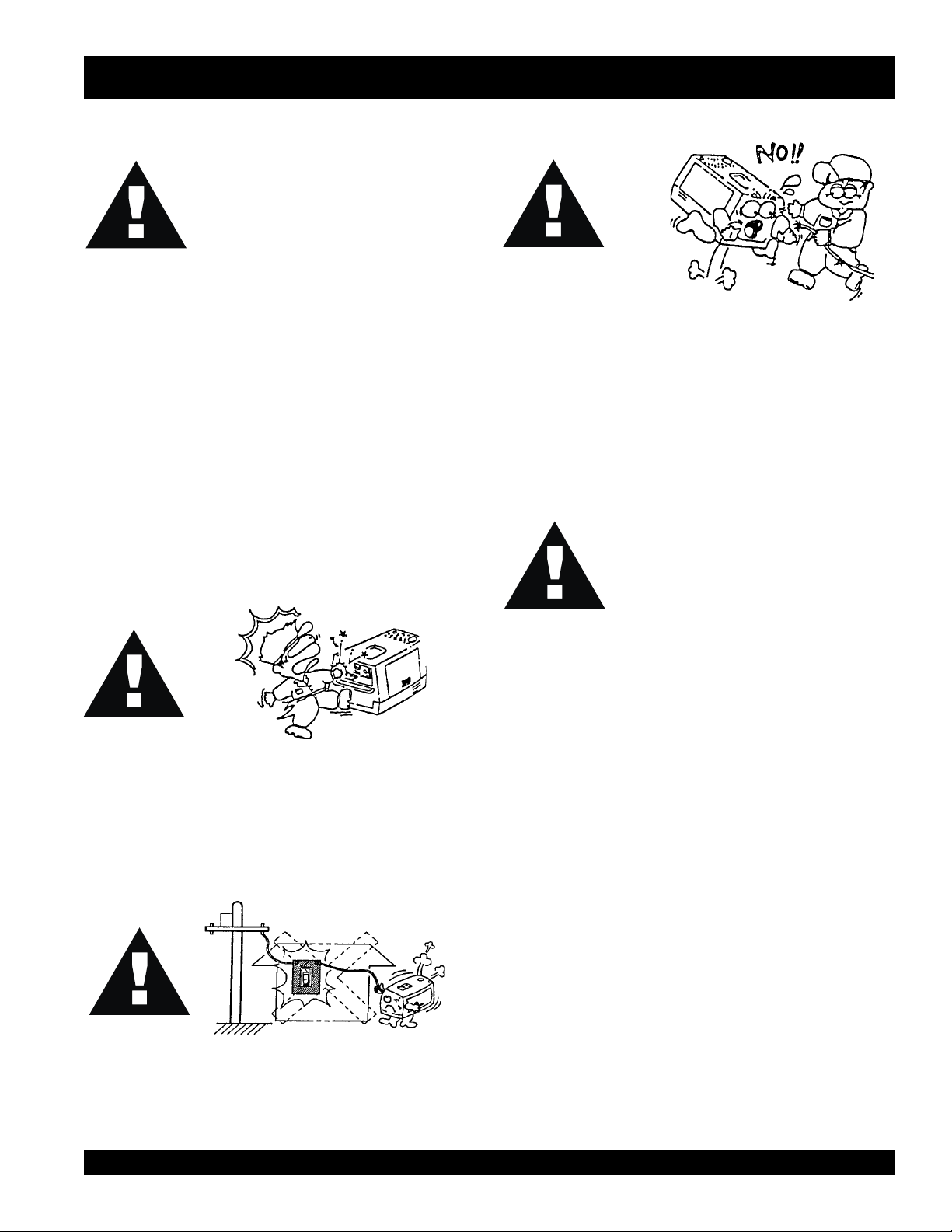
CAUTION:
This welder/AC generator is a source of
providing LETHAL high voltages. Never
permit unqualified personnel-especially
children to operate the welder/AC gener ator.
■
This welder/AC generator is equipped with a
for your protection. Always complete the grounding path from
the welder/AC generator to an external grounding source.
■
NEVER operate this welder/AC generator, or handle any
electrical equipment while standing in
while hands are wet, or in the rain. Dangerous electrical
shock could occur causing severe bodily harm or even death.
■
This welder/AC generator requires an adequate free flow of
cooling air. Never operate the welder/AC generator in any
enclosed or narrow area where free flow of the air is restricted.
If the air flow is restricted it will cause serious damage to the
welder/AC generator and may cause injury to people.
■
Arc rays can cause blindness. Always wear protective
shield when welding.
CAUTION
:
ground terminal
water , while bare foot,
CAUTION
■
Never use damaged or worn cables when connecting
power tools or equipment to the w elder/AC generator. Make
sure power connecting cables are securely connected to
the generator’s output terminals. Insufficient tightening of
the terminal connections may cause damage to the welder/
AC generator and electrical shock.
CAUTION
:
:
DO NOT touch or open coolant dr ain plug,
radiator cap, or engine oil drain plug while
the welder/AC generator is running. Always
allow sufficient time for the engine and
generator to cool before performing
maintenance.
Emergencies
■
Always know the location of the nearest
and
Also know the phone numbers of the nearest
■
NEVER touch output terminals or electrode during
operation. This is extremely dangerous. Always stop the
machine when contact with the output terminals and
welding electrode.
CAUTION
■
Never connect the welder/AC generator to house wiring.
This is illegal and very dangerous. Electrical shock could
occur causing damage to the welder/AC generator and
bodily harm even death.
:
doctor
in the case of an emergency .
Maintenance Safety
■
■
■
■
■
■
■
fire extinguisher
first aid kit
and
NEVER lubricate components or attempt service on a running
machine.
Always allow the machine a proper amount of time to cool
before servicing.
Keep the machinery in proper running condition.
Fix damage to the machine immediately and always replace
broken parts.
Dispose of hazardous waste properly . Examples of potentially
hazardous waste are used motor oil, fuel, coolant and fuel
filters.
DO NOT use plastic containers to dispose of hazardous
waste.
DO NOT pour waste, oil, coolant or fuel directly onto the
ground, down a drain or into any water source.
. Know the location of the nearest telephone.
ambulance
fire department
. This inf ormation will be invaluable
,
BLW-400SSW-WELDER/AC GENERATOR— PARTS & OPERATION MANUAL— REV. #1 (06/15/01) — PAGE 7
Page 8
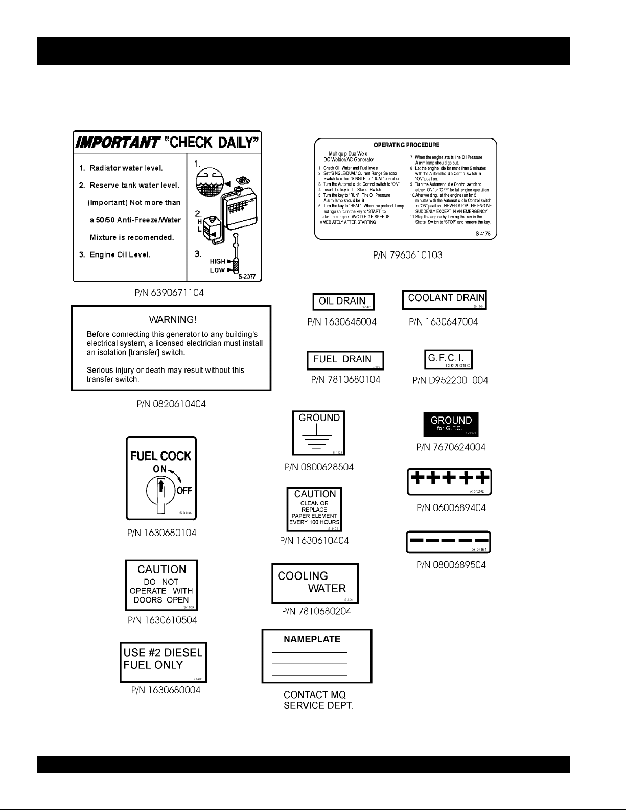
OPERA TION AND SAFETY DECALS
Table of Contents
PAGE 8 — BLW-400SSW- WELDER/AC GENERATOR — PARTS & OPERATION MANUAL — REV. #1 (06/15/01)
Page 9
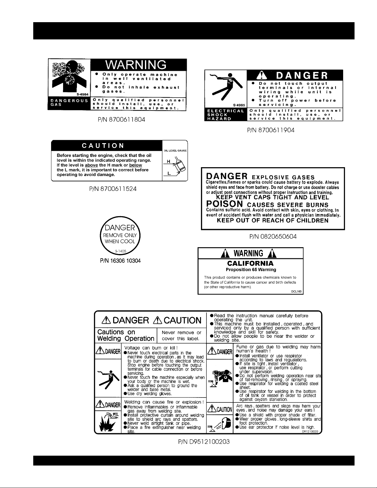
OPERA TION AND SAFETY DECALS
Table of Contents
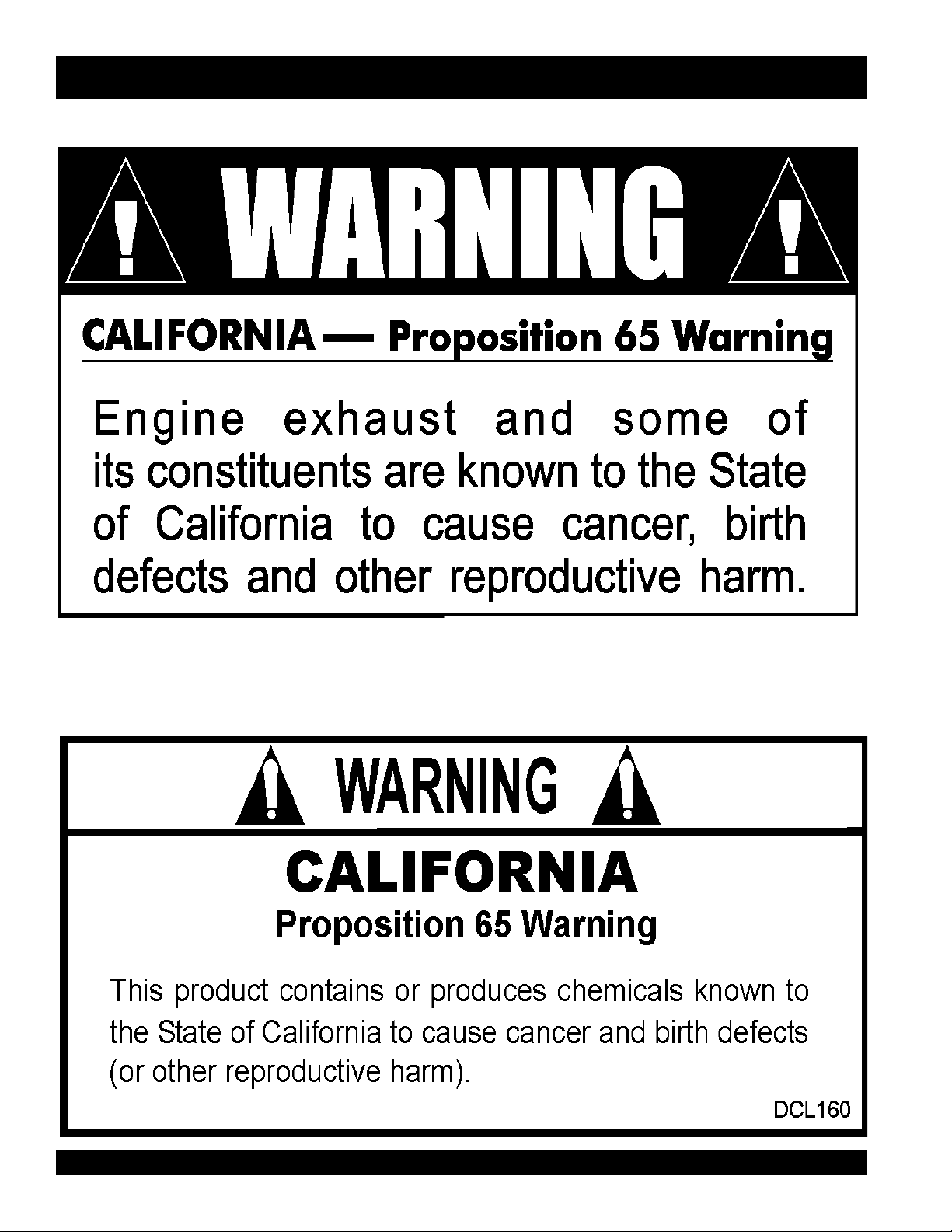
P/N DCL160
BLW-400SSW-WELDER/AC GENERATOR— PARTS & OPERATION MANUAL— REV. #1 (06/15/01) — PAGE 9
Page 10

BLW -400SSW — SPECIFICATIONS
Table of Contents
ledoMWSS004-WLB
epyTrotarenegepytdleif,gnivlover,sselhsurB
snoitacificepS.1elbaT
snoitacificepSredleW
noitcennoCerutamrA
tnerruCdetaRA053A571
egatloVdetaRV43V72
tnerruCfoegnaRA004~07A002~53
elgniSlauD
snoitacificepSrotareneG
ycneuqerFzH06
deepSmpr0063
tuptuO.xaMWk41
tuptuOdetaRWk5.21
egatloVV042/021
snoitacificepSenignE
ledoM5021VATOBUK
epyTevlavdaehrevo,enilni,delooc-retaw,elcyC4
srednilyCfo.oNsrednilyc4
ekortSxeroB)mm6.37xmm27(.ni9.2x.ni8.2
tuptuOdetaRmpr0063/PH5.13
tnemecalpsiD)cc8911(.ni.uc37
gnitratScirtcelE
yticapaCtnalooC)sretil5(.lag3.1
yticapaCliOebuL)sretil6(.lag6.1
noitpmusnoCleuF
yticapaCleuF)sretil04(lag6.01.xorppA
epytleuFleuFleseiD2#
yrettaBHA07-V21
.lag2gnidleW rh/)L5(
7(.lag1.2rewoPCA rh/)L9.
The maximum output of the engine listed above is applicable to supplying electrical power for continuous service at ambient
conditions in accordance with SAE Test cord J607. The above ambient conditions are at standard sea level, with a barometric
reading of 29.92 inches and a temperature of 60 degrees F ahrenheit.
°°
°
°°
Generally, the engine output power will decrease 3 1/2% for each 1000 feet of altitude above sea level, and 1% for each 10
°°
°
F ahrenheit above the standard temperature of 60
°°
F.
F
PAGE 10 — BLW-400SSW- WELDER/AC GENERATOR — PARTS & OPERATION MANUAL — REV. #1 (06/15/01)
Page 11

BLW -400SSW — GENERAL INFORMATION
Table of Contents
BL W -400SSW F AMILIARIZATION
Generator
The MQ Power Model BLW-400 welder/AC generator can
provide 400 amps of welding current with a single operator
or 200 amps of welding current simultaneously with two
operators. When used as a welder/AC generator it can
provide a maximum of 6,000 watts of power.
Control Panel
The
control panel
!
One GFCI 120 volt receptacle, 20 amp
!
One 120 volt receptacle, 30 amp
!
One 120/240 volt receptacle, 30 amp
!
Main Circuit Breaker 265V @25 amps
!
Circuit Protector Breaker (GFCI) 120V @20 amps
!
Idle Control Switch
!
Starter Switch
!
Warning Lamp Unit
!
Hour Meter
!
Ground T erminal
Engine Protection System
Engine protection fail safe features are provided in the event
of low oil pressure, high coolant temperature and failure of
the battery to charge. If any of the above conditions occur
while operating the welder/AC generator, it will cause a
complete unit shut down.
Battery Charge Indicator
This unit is equipped with a protective device that signals
an indicator and automatically stops the engine when the
battery cannot be charged by the alternator.
Water Temperature Indicator
This unit is equipped with an apparatus that signals an
indicator and automatically stops the engine when the cooling
water temperature becomes abnormally high. This apparatus
will not function properly if the machine is operated with
less than the proper amount of coolant.
is provided with the following:
Excitation System
The BL W -400SSW Welder/A C generator uses a brushless
exciter to create rated output electricity. This system will
use the mechanical energy generated by the 3600 RPM
engine to spin the rotor (or armature) inside the welder/AC
generator (or alternator end).
The motion created by the rotor (which holds copper coils)
spins inside a housing of permanent magnets called the
"STATOR". A magnetic field is created by the stator and
produces an electrical current.
Engine
The BL W -400SSW is powered by a 4-cycle KUBO TA
engine. This engine is designed to meet e v ery performance
requirement for welder/A C generator. Ref erence Table 1, page
10 for engine specifications.
In keeping with MQ Power's policy of constantly improving
its products, the specifications quoted herein are subject to
change without prior notice.
Idle Control Switch
The BL W-400SSW W elder/AC generator is pro vided with an
automatic idle (engine) control capability for noise
suppression and fuel cost reduction. The automatic idle
control feature automatically engages under a no-load
condition.
When the Idle Control Switch is placed in the “ON” position,
the engine revolutions will be approximately 2200 rpm (lowspeed operation). When a load is connected to one of the
output receptacles, the engine speed will automatically
increase to about 3600 rpm (high-speed operation) within 10
seconds. Con versely, when the load is removed, the engine
speed will automatically drop back down to 2200 rpm within
10 seconds.
diesel
Oil Pressure Warning Indicator
If low oil pressure is detected while operating the welder/AC
generator, the engine protection system will shut down the
engine.
If this condition (low oil pressure) should occur , please refer
to the engine troubleshooting table (page 44) in this manual.
BLW-400SSW-WELDER/AC GENERATOR— PARTS & OPERATION MANUAL— REV. #1 (06/15/01) — PAGE 11
Page 12
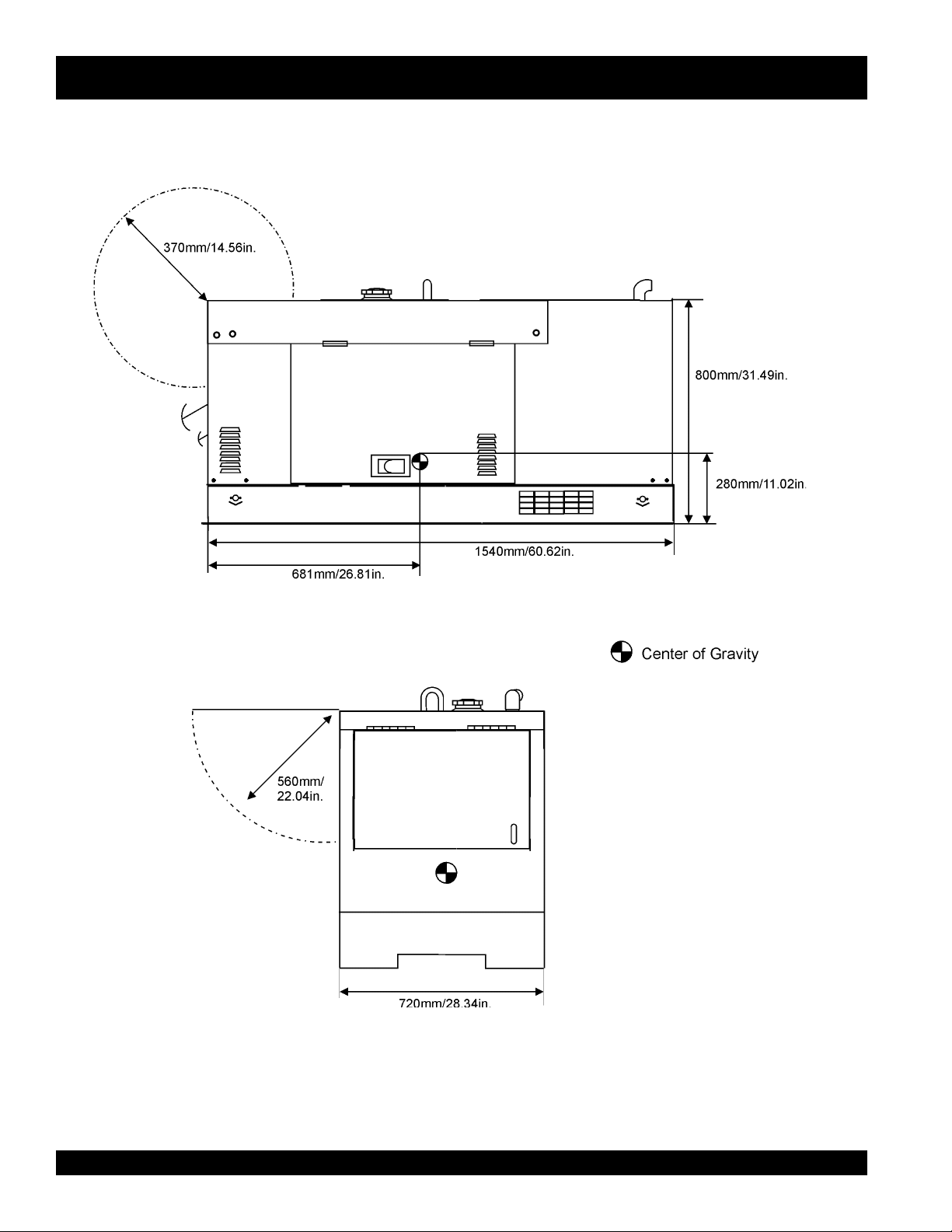
BLW -400SSW — DIMENSIONS
Table of Contents
PAGE 12 — BLW-400SSW- WELDER/AC GENERATOR — PARTS & OPERATION MANUAL — REV. #1 (06/15/01)
Figure 1. BLW-400SSW Dimensions
Page 13

BLW -400SSW — TRAILER-SAFETY GUIDELINES
Table of Contents
CAUTION:
ALWAYS make sure the trailer is in good
operating condition. Check the tires for
proper inflation and wear. Also check the
wheel lug nuts for proper tightness.
Explanation of Chart:
This section is intended to provide the user with trailer service and maintenance information. The service and maintenance guidelines referenced in this section apply a wide
range of trailers. Remember periodic inspection of the trailer
will ensure safe towing of the equipment and will prevent
damage to the equipment and personal injury .
It is the purpose of this section to cover the major maintenance components of the trailer . The following trailer components will be discussed in this section:
"
Brakes
"
Tires
"
Lug Nut T orquing
"
Suspension
"
Electrical
"
Brake Troubleshooting T ables
Use the following definitions with reading Table 2.
1. Fuel Cell - Provides an adequate amount of fuel for
the equipment in use. Fuel cells must be empty when
transporting equipment.
2. Braking System - System employed in stopping the
trailer . Typical braking systems are electric, surge, hydraulic, h ydraulic-surge and air.
3. GVWR- Gross Vehicle Weight Rating (GVWR), is the
maximum number of pounds the trailer can carry, including the fuel cell (empty).
4. Frame Length - This measurement is from the ball
hitch to the rear bumper (reflector).
5. Frame Width - This measurement is from fender to
fender.
6. Jack Stand - Trailer support device with maximum
pound requirement from the tongue of the trailer .
7. Coupler - Type of hitch used on the trailer for towing.
8. Tire Size - Indicates the diameter of the tire in inches
(10,12,14, etc.), and the width in millimeters
(175,185,205, etc.). The tire diameter must match the
diameter of the tire rim.
9. Tire Ply - The tire ply (lay ers) number is rated in letters;
2-ply,4-ply,6-ply, etc.
10. Wheel Hub - The wheel hub is connected to the trailer’s
axle.
11. Tire Rim - Tires mounted on a tire rim. The tire rim must
match the size of the tire.
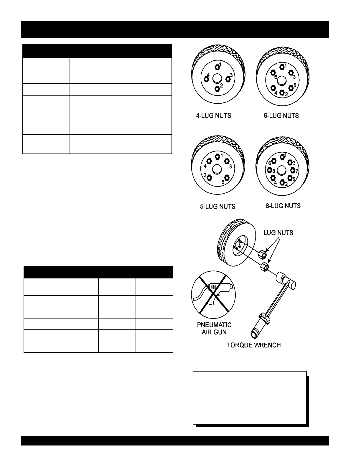
12. Lug Nuts - Used to secure the wheel to the wheel hub.
Always use a torque wrench to tighten down the lug
nuts. See Table 4 and Figure 5 or lug nut tightening and
sequence.
13. Axle - Indicates the maximum weight the axle can support in pounds, and the diameter of the axle expressed
in inches (see Table 3). Please not that some trailers
have a double axle. This will be shown as 2-6000 lbs.,
meaning two axles with a total weight capacity of 6000
pounds.
14. Suspension - Protects the trailer chassis from shocks
transmitted through the wheels. Types of suspension
used are leaf, Q-flex, and air ride.
15. Electrical - Electrical connectors (looms) are provided
with the trailer so the brake lights and turn signals can
be connected to the towing vehicle.
16. Application - Indicates which units can be employed
on a particular trailer.
BLW-400SSW-WELDER/AC GENERATOR— PARTS & OPERATION MANUAL— REV. #1 (06/15/01) — PAGE 13
Page 14

BLW -400SSW — TRAILER-SPECIFICATIONS
Table of Contents
snoitacificepS.2elbaT
LEDOM NOITACILPPA LEUF
LLEC
51-01-RLRT ,51ACD,21-GLT
X01-RLRT ,51ACD,21-GLT
FX01-RLRT ,51ACD,21-GLT
W522-RLRT 01-ACDONONSBL0022"58"24.BL008
004-WLB 004-WLBONCIRTCELESBL0072"451TSAM/W
FX51-RLRT 51-ACDLAG14ONSBL0072"421"55.BL008
X05-RLRT 52-ACDONONSBL0072"421"55.BL008
FX05-RLRT 52-ACDLAG14ONSBL0072"421"55.BL008
TBS52-RLRT 52-ACDONONSBL0992"021"66.BL008
W07-RLRT 07,06-,54-ACDONEGRUSSBL0007"681"77.BL0002
X07-RLRT 07,06-,54-ACDTPOEGRUSSBL0007"831"66.BL0002
FX07-RLRT 07,06-,54-ACDLAG35EGRUSSBL0007"831"66.BL0002
FX001-RLRT 521,001-ACDLAG051EGRUSCILUARDYHSBL0007"091"67.BL0002
521/58-RLRT ,001,58-ACD
FX051-RLRT 081,051-ACDLAG002EGRUSCILUARDYHSBL06111"402"48.BL0005
FX022-RLRT 022-ACDLAG052EGRUSCILUARDYHSBL00041"222"38.BL0005
FX003-RLRT 003-ACDLAG052EGRUSCILUARDYHSBL00081"832"38.BL0005
FX004-RLRT 004-ACDLAG053CIRTCELESBL00081"832"38.BL0005
FX006-RLRT 008,006-ACDLAG055RIASBL00003"483"69.BL0005
XS008-RLRT 008,006-ACDLAG055RIASBL00003"483"69.BL0005
003-WLT
003-WLT
003-WLT
521
ONONSBL0091"69"05.BL008
ONONSBL0091"69"05.BL008
LAG15ONSBL0091"69"05.BL008
LAG541CILUARDYHSBL00001"681"77.BL0002
EKARB
METSYS
RWVG EMARF
HTGNEL
"421O/W
HTDIW
"55
)LLAT"87(
EMARF
KCAJ
DNATS
LEEHWTLITLLUF
LEEHWTLITLLUF
LEEHWTLITLLUF
LEEHWTLITLLUF
.BL008
LEEHWTLITLLUF
LEEHWTLITLLUF
LEEHWTLITLLUF
LEEHWTLITLLUF
LEEHWTLITLLUF
DAPTALF
DAPTALF
DAPTALF
DAPTALF
DAPTALF
DAPTALF
DAPTALF
DAPTALF
DAPTALF
DAPTALF
DAPTALF
PAGE 14 — BLW-400SSW- WELDER/AC GENERATOR — PARTS & OPERATION MANUAL — REV. #1 (06/15/01)
Page 15

BLW-400SSW — TRAILER-SPECIFICATIONS
Table of Contents
)t'noC(snoitacificepS.2elbaT
LEDOM RELPUOC SERIT SLEEHW ELXA SBUH NOISNEPSUS LACIRTCELE
W51-01-RLRT SSALCLLAB"2
ELBATSUJDA2
X01-RLRT SSALCLLAB"2
ELBATSUJDA2
FX01-RLRT SSALCLLAB"2
ELBATSUJDA2
W522-RLRT SSALCLLAB"2
ELBATSUJDA2
004WLB SSALCLLAB"2
ELBATSUJDA2
FX51-RLRT SSALCLLAB"2CRL31-87B"05.4X"31"2/1-2#0053GUL5FAEL4REBBURELOP4
X05-RLRT SSALCLLAB"2CRL31-87B"05.4X"31.sbl0053
FX05-RLRT SSALCLLAB"2CRL31-87B"05.4X"31.sbl0053
W07-RLRT SSALCLLAB"2
ELBATSUJDA"3
X07-RLRT SSALCLLAB"2
ELBATSUJDA"3
FX07-RLRT SSALCLLAB"2
ELBATSUJDA"3
FX001-RLRT 6/5-2ELBATSUJDA
EYE"3TPO
521/58-RLRT 6/5-2ELBATSUJDA
EYE"3TPO
FX051-RLRT EYELLAB"3E61-057
FX022-RLRT EYE"3
ELBATSUJDA
FX003-RLRT EYE"3
ELBATSUJDA
FX004-RLRT EYE"3
ELBATSUJDA
FX006-RLRT LEEHWHT5H5.71R57/512TS
RA008-RLRT LEEHWHT5H5.71R57/512TS
C31-571"05.4X"312X2#0022GUL5FAEL3/WMOOLERIW4
C31-571"5.4X"312X2#0022GUL5FAEL3TALFELOP4
C31-571"5.4X"312X2#0022GUL5FAEL3TALFELOP4
B31-571"5.4X312X2#0022GUL5XELFQTALFELOP4
C31-571"5.4X312X2#0022GUL5FAEL3TALFELOP4
"8/3-2
"8/3-2
C41-502
)4(SAIB
C41-502
)4(SAIB
C41-502
)4(SAIB
C51-502
)4(SAIB
D51R57/522TS
)4(LAIDAR
)4(SAIB
E61R58/532TS
)4(LAIDAR
E61R58/532TS
)6(LAIDAR
E61R58/532TS
)6(LAIDAR
)8(LAIDAR
)8(LAIDAR
"5X"41.sbl0053
"3
"5X"41sbl0053
"3
"5X"41.sbl0053
"3
"5.5X"41sbl0053
"3
"6x"41sbl0006-)2(GUL6FAEL7MOOLERIW4
"7X"61sbl0006-)2(GUL8FAEL7MOOLERIW4
"7X"61sbl0007-)2(GUL8XELFQMOOLERIW4
"7X"61sbl0006-)2(GUL8XELFQMOOLERIW4
"7X"61.sbl0007-)3(GUL8XELFQMOOLERIW4
"7X"61sbl00001-)3(GUL8FAEL7MOOLERIW6
"7X"61sbl00001-)3(GUL8EDIR-RIAMOOLERIW6
GUL5FAEL4REBBURELOP4
GUL5FAEL4REBBURELOP4
GUL5FAEL5REBBURELOP4
GUL5FAEL5REBBURELOP4
GUL5FAEL5REBBURELOP4
GUL5FAEL5MOOLERIW4
TALFELOP4
TALF
TALF
TALF
TALF
TALF
TALF
BLW-400SSW-WELDER/AC GENERATOR— PARTS & OPERATION MANUAL— REV. #1 (06/15/01) — PAGE 15
Page 16
BLW -400SSW —TRAILER SAFETY GUIDELINES
Table of Contents
Brakes
If your trailer has a braking system, the brakes should be
inspected the first 200 miles of operation. This will allow
the brake shoes and drums to seat properly. After the first
200 mile interval, inspect the brakes every 3,000 miles. If
driving over rough terrain, inspect the brakes more
frequently.
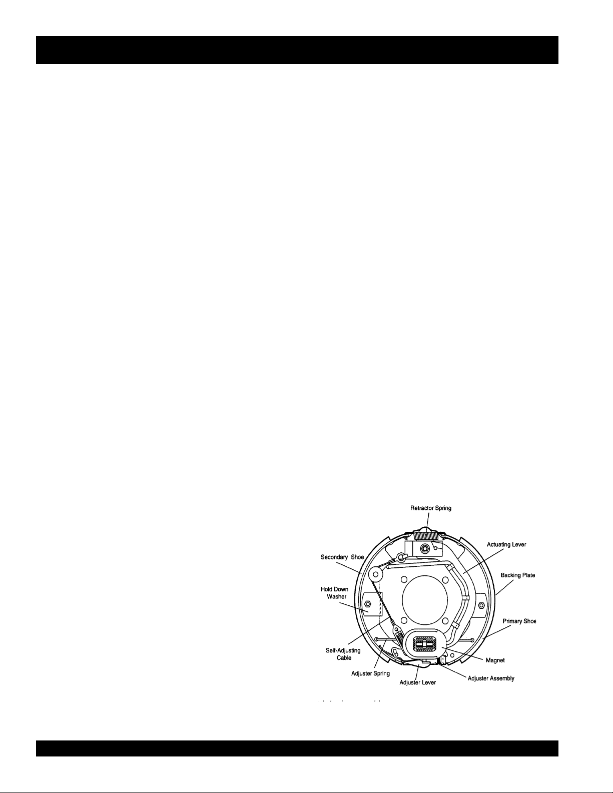
Electric Brakes
Electrically actuated brakes (Figure 2) are similar to
hydraulic brakes. The basic difference is that hydraulic
brakes are actuated by an electromagnet.
Listed below are some of the advantages that electric
brakes have over hydraulic brakes:
"
Brake system can be manually adjusted to provide
the corrected braking capability for varying road and
load conditions
"
Brake system can be modulated to provide more or
less braking force, thus easing the brake load on the
towing vehicle
"
Brake system has very little lag time between the time
the vehicle’s brakes are actuated and the trailer’s br akes
are actuated
"
Brake system can provide an independent emergency
brake system
Remember in order to properly synchronize the tow vehicle’s
braking to the trailer’s braking, can only be accomplished
by road testing. Brake lockup, grabbiness or harshness is
due to lack of synchronization between the tow vehicle
and the trailer being towed or under-adjusted brakes.
Before any brake synchronizations adjustments can be
made, the trailer brakes should be burnished-in by applying
the brakes 20-30 times with approximately a 20 m.p.h.
decrease in speed, e.g. 40 m.p.h. to 20 m.p.h. Allow ample
time for brakes to cool between application. This allows
the brake shoes to slightly be seated into the brake drum
surface.
Figure 2 displays the major electric brake components that
will require inspection and maintenance. Please inspect
these components as required.
Electric Brake Adjustment
1. Place the trailer on jack stands. Make sure the jack
stands are placed on secure level ground.
2. Check the wheel and drum for free rotation.
3. Remove the adjusting hole cover from the adjusting
slot at the bottom brake backing plate.
4. With a screwdriver or standard adjusting tool, rotate
the star wheel of the adjuster assembly to expand the
brake shoes.
5. Adjust the brake shoes outward until the pressure of
the lining against the wheel drum makes the wheel
difficult to turn.
6. Rotate the star wheel in the opposite direction until the
wheel rotates freely with slight lining drag.
7. Replace the adjusting hole cover and lower the trailer
to the ground.
8. Repeat steps 1 through 6 on the remaining brakes.
PAGE 16 — BLW-400SSW- WELDER/AC GENERATOR — PARTS & OPERATION MANUAL — REV. #1 (06/15/01)
Figure 2. Electrical Brake Components
Page 17
BLW -400SSW —TRAILER SAFETY GUIDELINES
Table of Contents
Tires/Wheels/Lug Nuts
Tires and wheels are a very important and critical
components of the trailer . When specifying or replacing the
trailer wheels it is important the wheels, tires, and axle are
properly matched.
CAUTION:
DO NOT attempt to repair or modify a
wheel. DO NOT install in inner tube to
correct a leak through the rim. If the rim
is cracked,
the air
pressure in
the inner tube may cause pieces
of the rim to explode (break off)
with great force and cause serious
eye or bodily injur y.
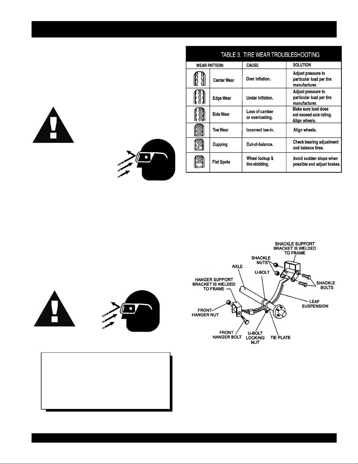
Tire Wear/Inflation
Tire inflation pressure is the most important factor in tire life.
Pressure should be checked cold bef ore operation DO NO T
bleed air from tires when they are hot. Check inflation
pressure weekly during use to insure the maximum tire life
and tread wear .
Table 3 (Tire Wear Troubleshooting) will help pinpoint the
causes and solutions of tire wear problems.
Suspension
The leaf suspension springs and associated components
(Figure 3) should be visually inspected every 6,000 miles for
signs of excessive wear, elongation of bolt holes, and
loosening of fasteners. Replace all damaged parts
(suspension) immediately . T orqued suspension components
as detailed in Tab le 4.
CAUTION:
NOTE
AL WAYS wear saf ety glasses when removing
or installing force fitted parts. Failure to
comply may result in serious injury.
BLW-400SSW-WELDER/AC GENERATOR— PARTS & OPERATION MANUAL— REV. #1 (06/15/01) — PAGE 17
Figure 3. Major Suspension Components
Page 18
metI ).sbL-.tF(euqroT
Table of Contents
TLOB-U"8/353-XAM03-NIM
TLOB-U"61/706-XAM54-NIM
TLOB-U"2/106-XAM54-NIM
BLW -400SSW —TRAILER SAFETY GUIDELINES
stnemeriuqeReuqroTnoisnepsuS.4elbaT
SHACKLE BOLT
SPRING EYE BOLT
SHOULDER TYPE
SHACKLE BOLT
SNUG FIT ONLY.PARTS MUST ROTATE FREELY
LOCKING NUTS OR COTTER PINS ARE PROVIDED TO
-
RETAIN NUT
BOLT ASSEMBLY
.
05-XAM03-NIM
.
Lug Nut T orque Requirements
It is extremely important to apply and maintain proper wheel
mounting torque on the trailer. Be sure to use only the
fasteners matched to the cone angle of the wheel. Proper
procedure for attachment of the wheels is as follows:
1. Star t all wheel lug nuts by hand.
2. Torque all lug nuts in sequence. See Figure 4. DO NO T
torque the wheel lug nuts all the way down. Tighten
each lug nut in 3 separate passes as defined by Tab le 5.
3. After first road use, retorque all lug nuts in sequence.
Check all wheel lug nuts periodically.
stnemeriuqeReuqroTeriT.5elbaT
eziSleehWssaPtsriF
SBL-TF
ssaPdnoceS
SBL-TF
ssaPdrihT
SBL-TF
"2152-0204-5356-05
"3152-0204-5356-05
"4152-0206-05021-09
"5152-0206-05021-09
"6152-0206-05021-09
PAGE 18 — BLW-400SSW- WELDER/AC GENERATOR — PARTS & OPERATION MANUAL — REV. #1 (06/15/01)
Figure 4. Wheel Lug Nuts Tightening Sequence
NOTE
NEVER use an pneumatic air gun to
tighten wheel lug nuts.
Page 19
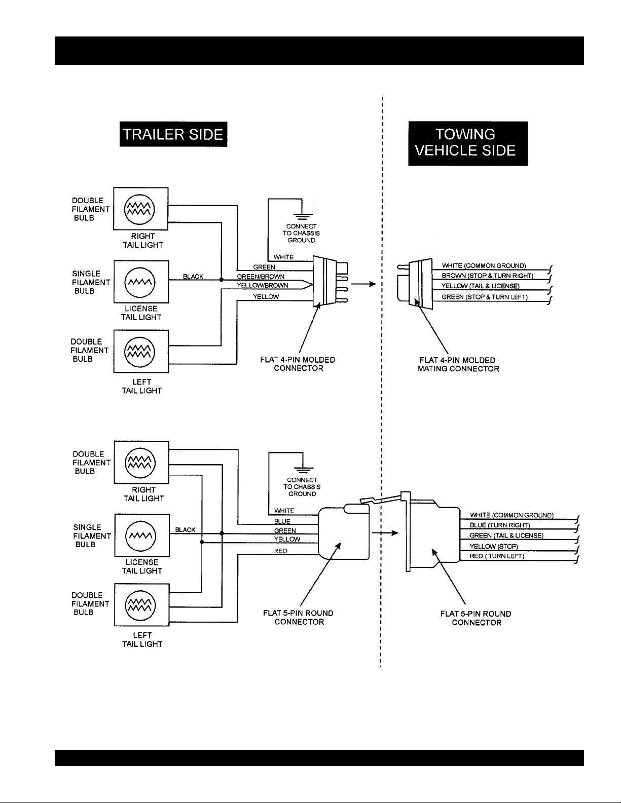
BL W -400SSW —TRAILER-WIRING DIA GRAM
Table of Contents
BLW-400SSW-WELDER/AC GENERATOR— PARTS & OPERATION MANUAL— REV. #1 (06/15/01) — PAGE 19
Page 20

BL W -400SSW —TRAILER-BRAKE TROUBLESHOOTING
Table of Contents
gnitoohselbuorTekarBcirtcelE.6elbaT
motpmyS esuaCelbissoP noituloS
sekarBtnettimretnIrosekarBoN?seriwnekorbrostiucricnepoynA.tcerrocdnadniF
?stiucrictrohsynA.tcerrocdnadniF
?rellortnocytluaF.tcerrocdnatseT
?snoitcennocesoolynA.riaperdnadniF
?eruceseriwdnuorG.erucesdnadniF
otlluPsekarBrosekarBkaeW
ediSenO
sekarBgnikcoL?nekorbrotneb,esoolstnenopmocekarB.stnenopmocecalpeR
sekarBysioN?detacirbulmetsyS.etacirbuL
sekarBgniggarD?detsujdaleehwehtfosgniraeB.tsujdA
?dedorrocsnoitcennoCesuactcerrocdnanaelC
?dezinorhcnyssekarB.tcerroC
?sgninilrostengamnolioroesaerG.ecalperronaelC
?devoorgroderocssmurdekarB.ecalperroenihcaM
?dnuor-fo-tuosmurdekarB.ecalpeR
?tcerrocstnenopmocekarB.tcerrocdnaecalpeR
.noisorrocfo
PAGE 20 — BLW-400SSW- WELDER/AC GENERATOR — PARTS & OPERATION MANUAL — REV. #1 (06/15/01)
Page 21
BLW-400SSW —TO WING
Table of Contents
Towing Safety Precautions
■
ALWAYS attach trailer's safety chain to bumper of towing
vehicle.
CAUTION :
■
ALWAYS make sure the vehicle and trailer directional,
Check with your county or state safety
towing regulations department before
towing your generator. Vehicle towing
codes and regulations can vary from state
to state.
To reduce the possibility of an accident while transporting
the generator on public roads, always make sure the trailer
(Figure 5) and the towing vehicle are in good operating
condition and both units are mechanically sound.
The following list of suggestions should be used when towing
your generator:
■
Make sure the hitch and coupling of the towing vehicle are
rated equal to, or greater than the trailer "gross vehicle weight
rating" (GVWR).
■
ALWAYS inspect the hitch and coupling for wear. NEVER
tow a trailer with defective hitches, couplings, chains etc.
■
Check the tire air pressure on both the towing vehicle and
the trailer . Also check the tire tread wear on both vehicles.
■
ALWAYS make sure the trailer is equipped with a "Safety
Chain".
backup, brake, and trailer lights are connected and are
working properly .
■
The maximum speed (unless otherwise posted) for highway
towing is 45 MPH. Recommended off-road towing is not to
exceed 10 MPH or less, depending on type of terrain.
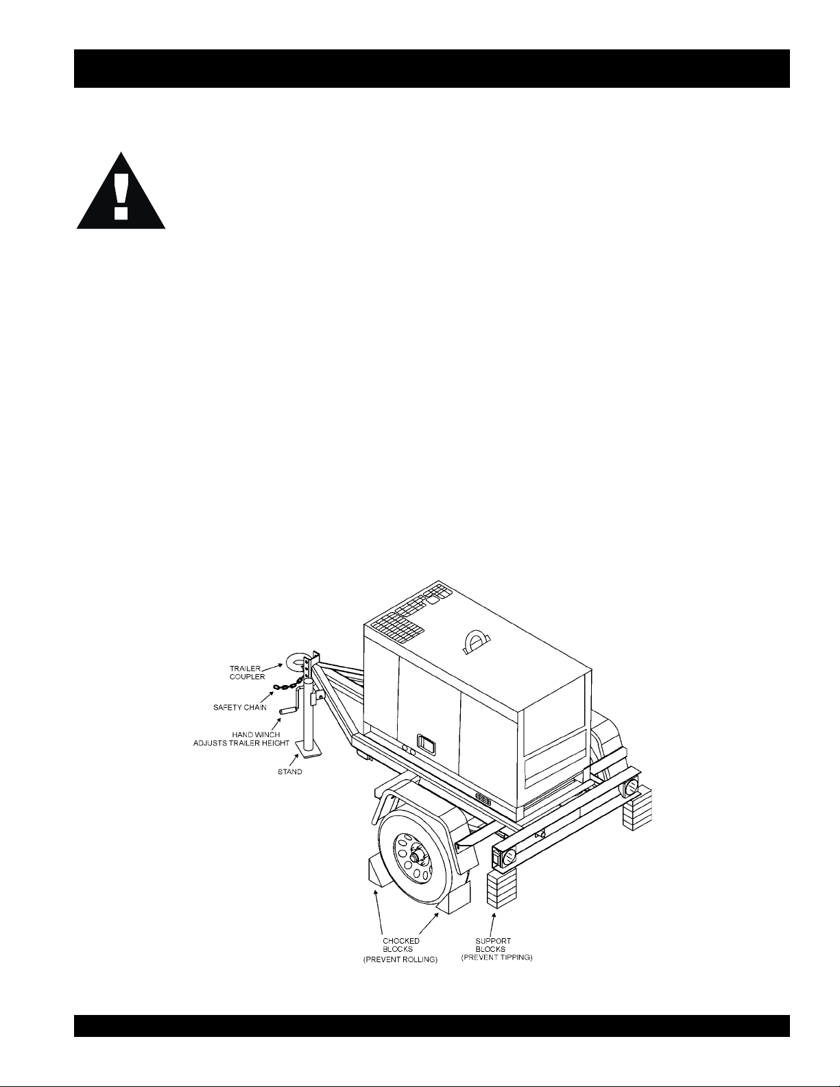
■
Place
while parked.
■
Place
prevent
■
Use the trailer's hand winch to adjust the height of the trailer ,
then insert locking pin to lock wheel stand in place, while
parked.
■
Av oid sudden stops and starts. This can cause skidding, or
jackknifing. Smooth, gradual starts and stops will improve
gas milage.
■
Avoid sharp turns to prevent rolling.
■
Remove wheel stand when transporting.
■
DO NOT transport generator with fuel in tank.
chocked blocks
support blocks
tipping
underneath wheel to prevent
underneath the trailer's bumper to
, while parked.
rolling,
BLW-400SSW-WELDER/AC GENERATOR— PARTS & OPERATION MANUAL— REV. #1 (06/15/01) — PAGE 21
Figure 5. Welder/AC Generator and Towing Trailer
Page 22
BLW -400SSW — CONTROLS AND INDICAT ORS
Table of Contents
PAGE 22 — BLW-400SSW- WELDER/AC GENERATOR — PARTS & OPERATION MANUAL — REV. #1 (06/15/01)
Figure 6. Controls and Indicators
Page 23

BLW -400SSW — CONTROLS AND INDICAT ORS
Table of Contents
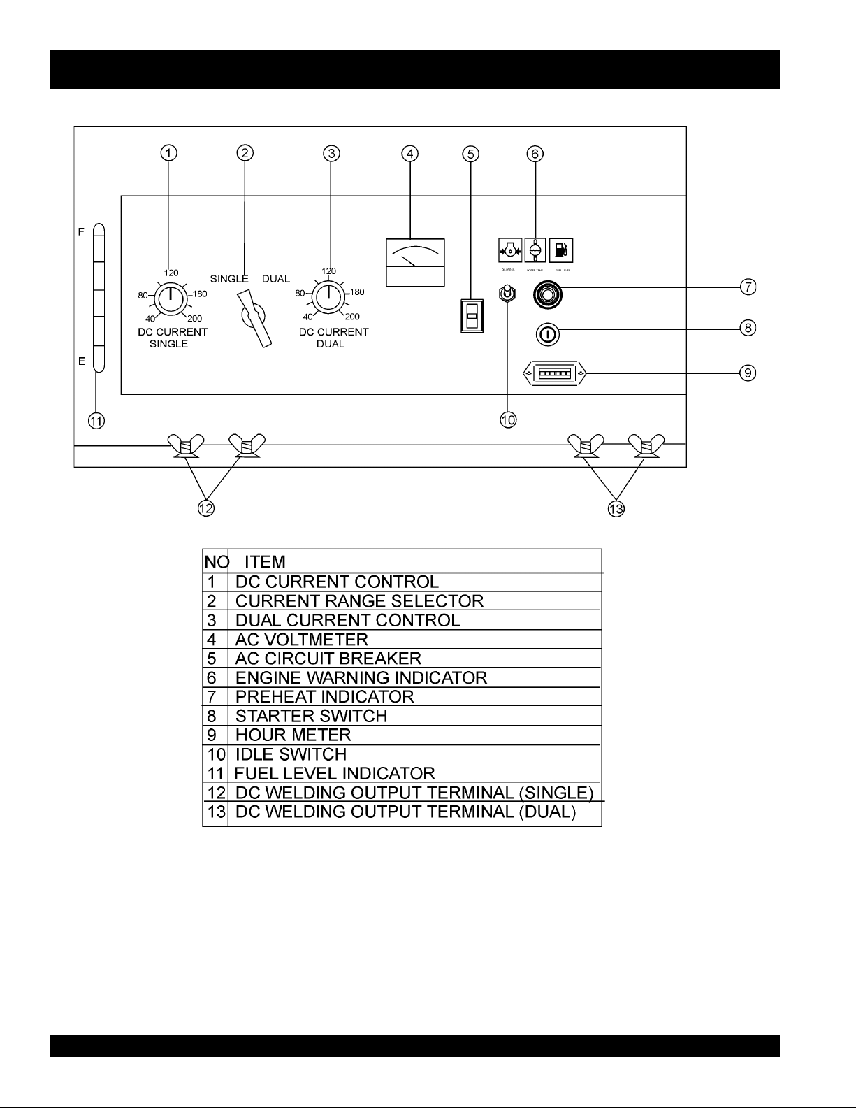
Figure 6 shows the location of the controls and indicators. The
functions of each control or indicator is described below .
1. DC Current Selector/Single-Use to select current when
using welder for single operator .
2. Current Range Selector- Use to select for single or dual
welding operators.
3. DC Current Selector/Dual- Use to select current when
using welder for dual operators.
4. AC Voltmeter-Indicates the output of total voltage with
welder and/or generator .
5. AC Circuit Breaker - This 53 amp main circuit breaker will
shut down current if welder/generator is overloaded.
6. Engine Indicator Lamps- Lights red when the following
conditions occur:
!
Low Oil Pressure
!
High Water T emperature
!
Electrical System Is Not Charging Properly
7. Preheat Indicator-Indicates the engine is warmed up for
welding/adding load.
8. Ignition Switch – With key inserted turn clockwise to start
engine.
9. Hour Meter – Indicates number of hours machine has
been in use or hours engine was run.
10. Idle Switch- T urn on for rpms to automatically adjust rpms
when a load is added.
11. Fuel Gauge – Indicates the amount of fuel in the fuel tank.
BLW-400SSW-WELDER/AC GENERATOR— PARTS & OPERATION MANUAL— REV. #1 (06/15/01) — PAGE 23
Page 24
BLW -400SSW — OUTPUT TERMINAL OVER VIEW
Table of Contents
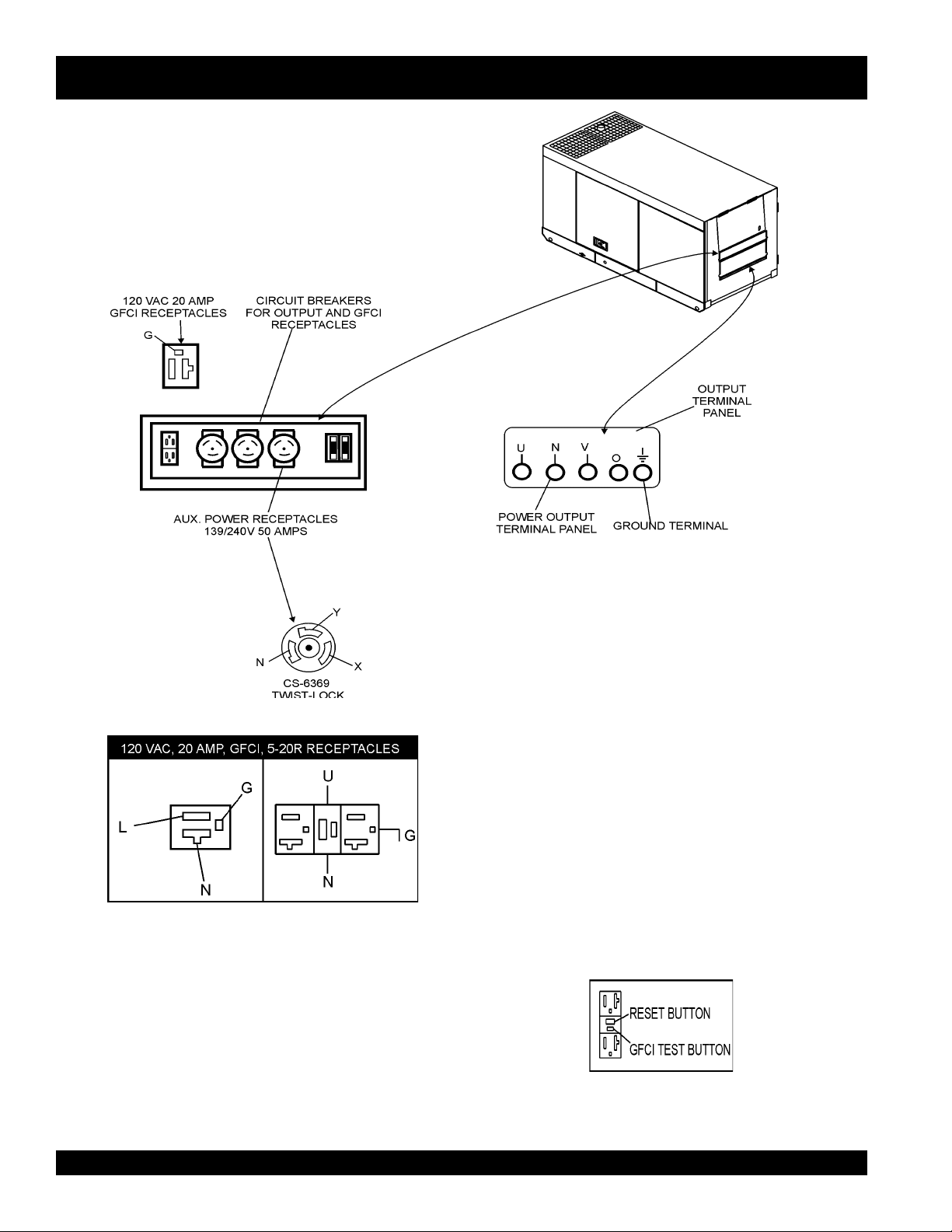
Figure 8. Duplex Receptacle Detail
Figure 7. Output Terminal Panel
120 V olt Receptacle
One GFCI Duplex Nema 5-20R (120V, 20 Amp) receptacle
is provided on the output terminal. This receptacle can be
used anytime the generator is in operation. The receptacle
is controlled by the circuit breaker located on the control
panel.
The reset button is for the GFCI when the circuit is tripped.
Pressing the "Test Button" (See Figure 9) in the center of
this receptacle will check the GFCI function. The receptacle
should be tested at least once a month.
PAGE 24 — BLW-400SSW- WELDER/AC GENERATOR — PARTS & OPERATION MANUAL — REV. #1 (06/15/01)
Figure 9. GFCI Test Button
Page 25
BLW-400SSW — OUTPUT TERMINAL OVERVIEW
Table of Contents
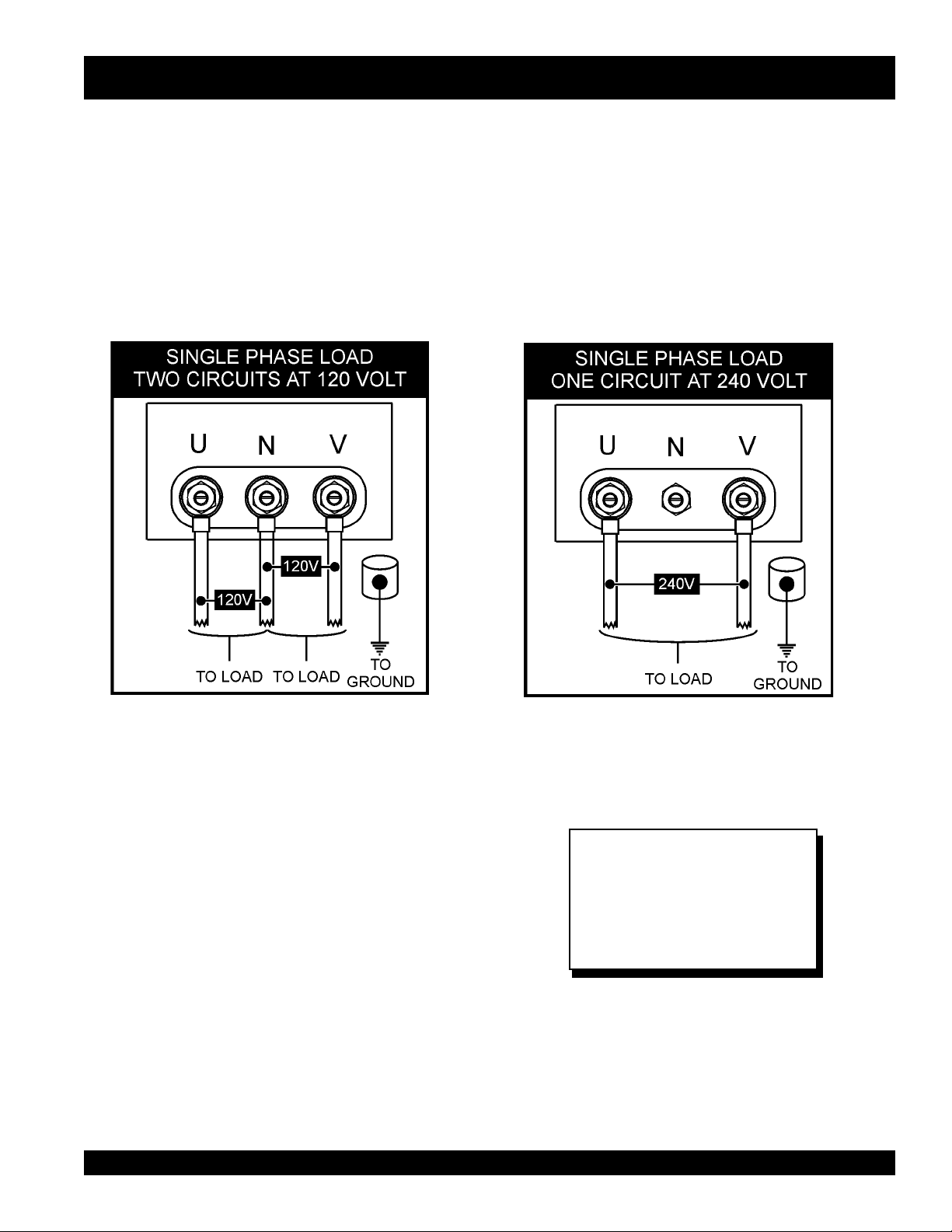
Output T erminal Panel Available V olta ges
The BLW-400SSW is a single phase generator only. It is
able to supply both 120 volt and 240 volt.
120V Hard Wire Hookup
The output terminal panel, when suppling single phase 120
volts, will provide two circuits available at 41.7 amps with
any two wires plus the ground. (See Figure 10 below.)
Maximum Amps
The BLW-400SSW can provide 41.7 amps at 120 or 240
volts. Do not exceed the maximum amps!
240V Hard Wire Hookup
The output terminal panel, when suppling single phase 240
volts, will provide one circuit available at 41.7 amps with
two wires plus the ground. (See Figure 11 belo w.)
Figure 10. Hard Wire Hookup for
120 Volt
BLW-400SSW-WELDER/AC GENERATOR— PARTS & OPERATION MANUAL— REV. #1 (06/15/01) — PAGE 25
Figure 11. Hard Wire Hookup for
240 Volt
NOTE
When using plural single phase
voltages, make sure to balance
the load on each of the single
phase legs.
Page 26

BLW -400SSW — INSTALLATION
Table of Contents
Outdoor Installation
Install the welder/AC generator in a location where it will not
be exposed to rain or sunshine. Make sure the Welder/AC
generator is on secure level ground so it cannot slide or
shift around. Also install the welder/AC generator so the
exhaust will not be discharged in the direction of nearby
homes.
The installation site must be relatively free from moisture
and dust. All electrical equipment should be protected from
excessive moisture. Failure to do will result in deterioration
of the insulation, and will result in short circuits.
Foreign materials such as dust, sand, lint and abrasive
materials will cause excessive wear to engine and alternator
parts.
Indoor Installation
Exhaust gases from diesel engines are extremely poisonous.
Whenever an engine is installed indoors the exhaust fumes
must be vented to the outside. The engine should be installed
at least two feet from any outside wall. Using an exhaust
pipe which is too long or too small can cause excessive
back pressure and cause the engine to heat excessively.
BLW -400SSW — INSTALLATION
Eliminate the danger of deadly carbon monoxide gas.
Remember that exhaust fumes from any diesel engine are
very poisonous if discharged in a closed room, but harmless
if allowed to mix with the outside air. If the welder/AC
generator is installed indoors, you must make provisions for
venting the engine exhaust to the outside of the building.
CAUTION :
CAUTION :
Pay close attention to ventilation when
operating the welder/AC generator inside
tunnels and caves. The engine exhaust
contains noxious elements.
An electric shock may happen when
vibrators are used. Pay close attention to
handling when operating vibrators and
always use rubber boots and gloves to
insulate the body from a electrical shock.
PAGE 26 — BLW-400SSW- WELDER/AC GENERATOR — PARTS & OPERATION MANUAL — REV. #1 (06/15/01)
Page 27

BLW-400SSW — PRE-SETUP
Table of Contents
General Inspection Prior to Operation
The BLW-400SSW utiliz es a welder/AC generator that has
been thoroughly inspected and accepted prior to shipment
from the factory. However, be sure to check for damaged
parts or components, or loose nuts and bolts, which could
have occurred in transit.
Ground
The nut and ground terminal on the welder/AC generator
should always be used to connect to a suitab le ground. The
ground path should be of #8 size wire.
Connect the terminal of the ground wire between the lock
washer and the nut and tighten the nut fully. Connect their
end of the wire to a suitable ground.
Circuit Breakers
To protect the welder/AC generator from an ov erload,
53 amp,
pole, 25 amp breaker is provided f or the G.F.C.I. receptacles .
Make sure to switch both circuit breakers to the "OFF"
position prior to starting the engine.
Extension Cable
When electric power is to be provided to various tools or loads at
some distance from the welder/AC gener ator , e xtension cords
are normally used. Cables should be sized to allow for distance
in length and amperage so that the voltage drop between the
welder/AC generator and point of use (load) is held to a
minimum. Use the cable selection chart (T ab le 7 ) as a guide for
selecting proper cable size.
sttaWnIdaoLhtgneLelbaCelbawollAmumixaM
nitnerruC
serepmA
021tA
stloV
042tA
eriW01#eriW21#eriW41#eriW61#
stloV
a 3-pole,
main
circuit breaker is provided. In addition 2-two
)noitarepOesahPelgniS,zH06(noitceleSelbaC.7elbaT
5.2003006.tf0001.tf006.tf573.tf052
50060021.tf005.tf003.tf002.tf521
5.70090081.tf053.tf002.tf521.tf001
0100210042.tf052.tf051.tf001
5100810063.tf051.tf001.tf56
0200420084.tf521.tf57.tf05
.egatlovwolmorftlusernacegamadtnempiuqE:NOITUAC
BLW-400SSW-WELDER/AC GENERATOR— PARTS & OPERATION MANUAL— REV. #1 (06/15/01) — PAGE 27
Page 28
BLW-400SSW — PRE-SETUP
Table of Contents
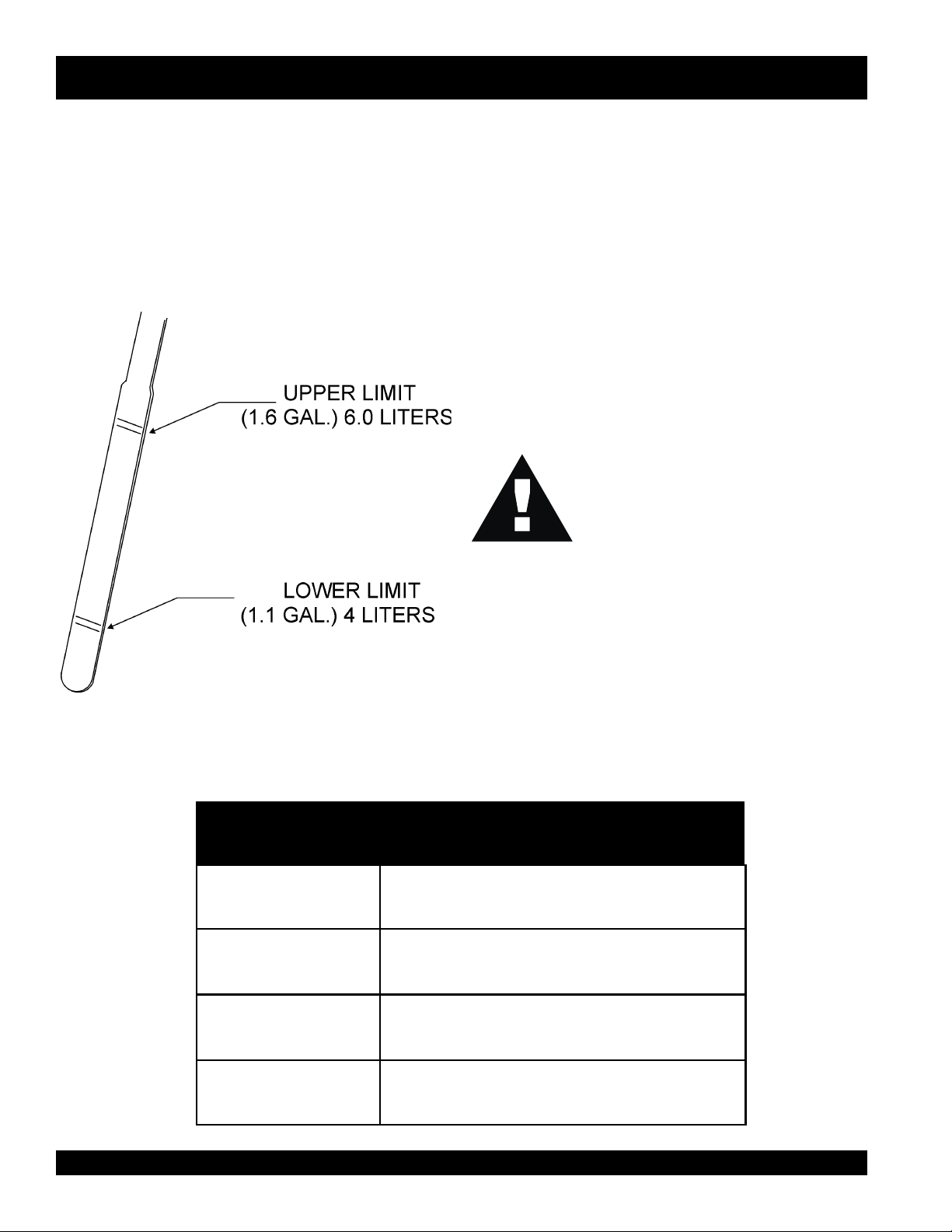
Lubrication Oil
Fill the engine crankcase with lubricating oil through the filler
hole, but do not overfill. Make sure the welder/AC generator
is level. With the dipstick inser ted all the way, but without
being screw into the filler hole, verify that the oil level is
maintained between the two notches (Figure 12) on the
dipstick. See Table 8 for proper selection of engine oil.
Fuel
Fill the fuel tank with clean diesel fuel. Do not fill the tank
beyond capacity.
Pay attention to the fuel tank capacity when replenishing
fuel. Refer to the fuel tank capacity listed on page 10
Specification Table 1.
The fuel tank cap must be closed tightly after filling. Handle
fuel in a safety container. If the container does not have a
spout, use a funnel.
CAUTION :
Coolant
Never fill the fuel tank while the engine is
running or in the dark. Fuel spillage on a
hot engine can cause a fire or explosion.
If fuel spillage occurs, wipe up the spilled
gasoline completely to prevent fire
hazards.
Figure 12. Engine Oil Dipstick
egnaRerutarepmeTliOepyT
F°32~F°401
)C°5-~C°04(
F°5~F°32
)C°51-~C°5-(
Use only drinkable tap water. If hard water or water with
many impurities is used, the inside of the engine and radiator
may become coated with deposits and cooling efficiency
will be reduced.
An anticorrosion additive added to the water will help prevent
deposits and corrosion in the cooling system. See the
Kobota Engine Operator's Manual
for further details.
liOrotoMdednemmoceR.8elbaT
03EAS
03-W01EASro02EAS
PAGE 28 — BLW-400SSW- WELDER/AC GENERATOR — PARTS & OPERATION MANUAL — REV. #1 (06/15/01)
)°51-(C°5woleB03-W01EASroW01EAS
Page 29
BLW-400SSW — PRE-SETUP
Table of Contents
CAUTION
Day-to-day addition of coolant or antifreeze is done from the
reserve tank. See Table 9 for engine, radiator and reserve
tank coolant capacities. Make sure the coolant level in the
reserve tank is always between the "H" and the "L" markings.
Operation in Freezing Weather
When operating in freezing weather , be certain that the proper
amount of antifreeze has been added. See Table 10 for
antifreeze operating temperatures.
:
When adding coolant or antifreeze to the
radiator, do not remove the radiator cap
until the unit has completely cooled.
yticapaCtnalooC.9elbaT
rotaidaRdnaenignE)L61.4(.laG1.1
knaTevreseR)L57.0(.laG2.0
Cleaning the Radiator
The radiator may overheat if the fins become overloaded
with dust or debris. Periodically clean the radiator fins with
compressed air .
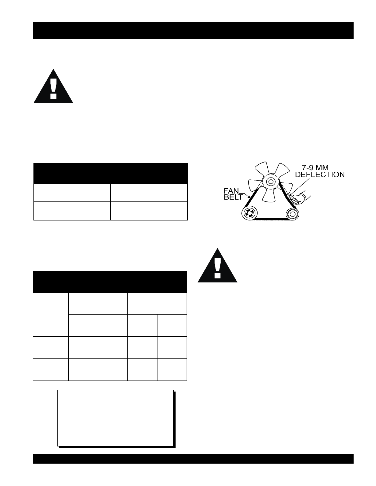
Fan Belt Tension
A slack fan belt may contribute to overheating, or to
insufficient charging of the battery. Inspect and adjust it in
accordance with the
The fan belt tension is proper if the fan belt (Figure 5) bends
7 to 9 mm (0.28- to 0.35 in.) when depressed with the thumb
as shown in Figure 13 below.
CAUTION :
Kubota Engine Operator's Manual
Figure 13. Fan Belt Tension
Never place hands near the belts or fan
while the welder/AC generator is running.
.
serutarepmeTgnitarepOezeerF-itnA.01elbaT
Air Cleaner
tnioPgnizeerFtnioPgnilioB
%loV
ezeerF-itnA
C° F° C° F°
0442-21-601222
0573-43-801622
NOTE
When the antifreeze is mixed with
water, the antifreeze mixing ratio must
be less than 50%.
BLW-400SSW-WELDER/AC GENERATOR— PARTS & OPERATION MANUAL— REV. #1 (06/15/01) — PAGE 29
Periodic cleaning/replacement is necessar y. Inspect it in
accordance with the
Battery
This unit is of negative ground. DO NO T connect in rev erse.
Always maintain battery fluid level between the specified
marks. Battery life will be shortened, if the fluid level is not
properly maintained. Add only distilled water when
replenishment is necessary.
The battery is sufficiently charged if the specific gravity of
the battery fluid is 1.28 (at 68° F). If the specific gravity
should fall to 1.245 or lower, it indicates that the battery is
dead and needs to be recharged or replaced.
Check to see whether the battery cables are loose. Poor
contact may result in poor starting or malfunctions, always
keep the terminals firmly tightened. Coating the terminals
with a thin film of grease will help to inhibit corrosion.
Kobota Engine Operator's Man ual.
Page 30
BLW -400SSW — LO AD APPLICATION
Table of Contents
Single Phase Load
CAUTION:
Always be sure to check the nameplate on the welder/AC
generator and equipment to insure the wattage, amperage
and frequency requirements are satisfactorily supplied by
the welder/AC generator for operating the equipment.
Generally, the wattage listed on the nameplate of the
equipment is its rated output. Equipment may require 130—
150% more wattage than the rating on the nameplate, as
An inadequate size connecting cable which cannot carry
the required load can cause a voltage drop which can burn
out the appliance or tool and overheat the cable.
the wattage is influenced by the efficiency, power factor
and starting system of the equipment.
The idle control is operated at minimum load capacity of
100W. If the load capacity is less than 100W, change the
idle control switch to the "OFF" position.
NO TE
If wattage is not given on the
equipment's name plate, approximate
CAUTION:
wattage may be determined by
multiplying nameplate voltage by the
nameplate amperage.
WATTS = VOLTAGE x AMPERAGE
The power factor of this welder/AC generator is 1.0. See
Table 11 below when connecting loads.
When connecting ordinary power tools, a capacity of up to
the generating set’s rated output (kW) multiplied by 0.8 can
daoLyBrotcaFrewoP.11elbaT
be used. Use Table 12 below for proper welding electrode
size for power capacity.
daoLfOepyTrotcaFrewoP
Motors and motor-driven equipment draw
much greater current for starting than
during operation.
Before connecting this welder/AC
generator to any building’s electrical
system, a licensed electrician must install
an isolation (transfer) switch. Serious
injury or death may result without this
transfer switch.
srotomnoitcudniesahp-elgniS57.0-4.0
tnecsednacni,sretaehcirtcelE
spmal
spmalyrucrem,spmaltnecseroulF9.0-4.0
noitacinummoc,secivedcinortcelE
tnempiuqe
slootrewopnommoC8.0
!
When connecting a resistance load such as an
0.1
0.1
incandescent lamp or electric heater, a capacity of up
to the generating set’s rated output (kW) can be used.
!
When connecting a fluorescent or mercury lamp, a
capacity of up to the generating set’s rated output (kW)
multiplied by 0.6 can be used.
!
When connecting an electric drill or other power tools,
pay close attention to the required starting current
capacity.
PAGE 30 — BLW-400SSW- WELDER/AC GENERATOR — PARTS & OPERATION MANUAL — REV. #1 (06/15/01)
With AC loads of more than 150W (such as lighting
equipment, motor-powered tools, submersible water pumps,
etc.), the engine runs at high speed. When a no load condition
is produced, the engine automatically slows down.
Turn the idle control switch to the “ON” (up) position when
AC loads of more than 150W are connected. Turn the idle
control switch to the “OFF” (down) position when AC loads
of less than 100W or when a magnetic switch is used.
rewoPCAdnaedortcelE.21elbaT
yticapaC
edortcelEgnidleW
eziS
0Wk41
"8/1OT"23/3Wk6
"23/5Wk4
"61/3Wk2
"4/1OT"23/7Wk1
ecruoSrewoPCA
yticapaC
Page 31

BLW-400SSW— WELDER OPERA TING INSTRUCTIONS
Table of Contents
Welding Cables and Polarities
Connect the welding cables (Figure 14) to the welder's output
terminals located on the control panel. The output terminals
have (+) and (-) polarities. Select the appropriate polarities
according to the application (See Welding Applications,
T ab le 13).
NOTE
ALWAYS attach terminal connectors at
the end of each cable. NEVER connect
exposed or frayed wires (Figure 15)
directly to the terminals. Exposed wiring
may cause shocks or di-electric
breakdown from poor contact.
Figure 14. Electrode Cable Connection
(Correct)
YTIRALOPDOHTEMGNIDLEWSNOITACILPPALACIPYT
...
)+(
thgiartS
ytiraloP
Figure 15. Electrode Cable Connection
(Incorrect)
snoitacilppAgnidleW.31elbaT
pmalCdnuorG
)lateMesaB(
gniguogriA
redloHedortcelE...)-(
yollareppocrofgnidlewcrA
larenegrofslairetamleetsgnidleW
setalpssenkcihtdna,serutcurts
BLW-400SSW-WELDER/AC GENERATOR— PARTS & OPERATION MANUAL— REV. #1 (06/15/01) — PAGE 31
redloHedortcelE...)+(
esreveR
...
ytiraloP
)-(
pmalCdnuorG
)lateMesaB(
gnidlewpu-dliuB
setalpnihtfognidlewcrA
leetssselniatsfognidlewcrA
Page 32

BLW-400SSW— WELDER OPERA TING INSTRUCTIONS
Table of Contents
Duty Cycle
The welder is rated at 100% duty cycle at 350 amps.
Howe ver , the duty cycle depends upon the welding current
and number of operators. Select the appropriate duty
cycle from Table 14 to prevent overload.
elcyCytuD.41elbaT
3. Correct Arc Length
If the arc is too long or voltage too high the metal melts off the
electrode in large globules which wobble from side to side as
the arc wavers, giving a wide, spattered and irregular bead–
with poor fusion between original metal and deposited metal.
If the arc is too short or voltage too low, there is not enough
heat to melt the base metal properly and the electrode quite
often sticks to the work. This gives a high, uneven bead,
having irregular ripples and poor fusion.
%elcyCytuD00157
4. Correct Travel Speed
ELGNISsselro053004
)A(tnerruC
LAUDsselro071002
FIVE ESSENTIALS FOR PROPER
WELDING PROCEDURES
Besides the steady sizzling sound that a correct arc produces,
the shape of the molten pool and the movement of the metal at
the rear of the pool serve as a guide in checking weld quality.
In a correctly made deposit, the ripples produced on the bead
will be uniform and the bead will be smooth, with no overlap
or undercut.
1. Correct Electrode Size
The correct choice of electrode size involves consideration of
a variety of factors. Such as the type, position, and preparation
of the joint, the ability of the electrode to carry high current
values without injury to the weld metal or loss of deposition
efficiency. The mass of work metal and its ability to maintain its
original properties after welding, the characteristics of the
assembly with reference to effect of stresses set up by heat
application, the practicability of heat treatment before and/or
after welding, the specific requirements as to welding quality
and the cost of achieving the desired results.
2. Correct Current
If current on equipment is too high or too low, you are certain
to be disappointed in your weld. If too high, the electrode melts
too fast and your molten pool is large and irregular. If too low,
there is not enough heat to melt the base metal and your
molten pool will be too small, will pile up, and look irregular.
When your speed is too fast: your pool does not last long
enough, impurities and gas is locked in. The bead is narrow
and ripples pointed. When speed is too slow: the metal piles
up, the bead is high and wide, with a rather straight ripple.
5. Correct Electrode Angle
The electrode angle is of particular importance in fillet
welding and deep groove welding. Generally speaking, when
making a filet weld, the electrode should be held so that it
bisects the angle between the plates and is perpendicular to
the line of weld. If under cut occurs in the vertical member
lowers the angle of the arc and directs the arc toward the
vertical member.
CAUTION :
Under the above conditions, the
supply a welding current of 120 amps, and
the
3 kW of power at either 120 or 240 volts.
Always wear welding shield with correct filter
shade when welding.
NOTE
welder/AC generator
can supply up to
welder
can
PAGE 32 — BLW-400SSW- WELDER/AC GENERATOR — PARTS & OPERATION MANUAL — REV. #1 (06/15/01)
Page 33

BLW-400SSW— START-UP INSTRUCTIONS
Table of Contents
START UP INSTRUCTIONS
5. Connect the battery cables to the battery with red
1. Check the oil level before starting the engine.
Replenish if necessary. Use specified oil as indicated
on page 28, Table 8.
2. Check the coolant level in the radiator and subtank.
Always maintain the antifreeze level between the ‘Full’
and ‘Lo w ’ level. Fasten the radiator cap securely.
CAUTION:
The engine's exhaust contains harmful
emissions.
exhaust when operating inside tunnels,
excavations or buildings. Direct exhaust
away from nearby personnel.
3. Check the fuel level and replenish as necessary. Turn
the fuel cock lever to the ‘ON’ position (Figure 16)
located inside the engine compartment.
ALWAYS
ventilate the
6. Set the “Current Range Selector” switch (Figure 19) to
terminal to positive and black to negative (Figure 18).
DO NOT CONNECT IN REVERSE.
NEGATIVE
POSTIVE
BATTERY
Figure 18. Battery connection
‘Single’ for one operator or ‘Dual’ f or two operators .
Figure 16. Fuel Cock ‘ON’ position
4. Connect load and welding apparatus to output
terminals (Figure 17). Check the circuit breakers are in
the ‘OFF’ position.
Figure 17. Terminal Connection and Circuit
Breakers
Figure 19. Current Range Selector Switch
7. Always operate the welder with the doors closed
(Figure 20). Operation with the doors open may cause
insufficient cooling to the unit, and may damage the
unit.
Figure 20. Doors in closed position
BLW-400SSW-WELDER/AC GENERATOR— PARTS & OPERATION MANUAL— REV. #1 (06/15/01) — PAGE 33
Page 34

BLW-400SSW— START-UP INSTRUCTIONS
Table of Contents
8. Turn the Automatic Idle Control switch to the ‘OFF’
position (Figure 21).
Figure 21. Automatic Idle Control Switch in
‘OFF’ position
9. Insert the key into the starter switch and turn the ‘Run’
position (Figure 22). The oil pressure light will
temporarily turn on.
Figure 22. Starter Switch to ‘RUN’ position
10. Turn the key further to the ‘Heat’ position. The preheat
light will go on (Figure 23). Once the light turns off,
the engine is ready to operate.
CAUTION:
NEVER turn the key to the “
position while the engine is running.
12. Switch the engine idle switch to ‘On’ and let engine
idle for about 5 minutes. Check the engine for
abnormal vibrations or sounds. Turn the engine idle
switch to either ‘Off’ or keep in ‘On (Figure 25)’ position
for full engine operation.
Figure 25. Automatic Idle Control Switch in the
’ON’ position
13. Once the engine is running and operating properly ,
switch the circuit breakers to ‘ON’ position (Figure 26).
START
”
Figure 23. Starter Switch to ‘HEAT’ position
11. Turn the key to the ‘Start’ position (Figure 24) to start
the engine, then release the key. Check the engine
indicators. If the oil pressure is still on, turn off the
engine and check the oil. If the engine does not start
within 10 seconds after the key is turned to the ‘Start’
position, release the key, and wait 30 seconds.
Repeat procedure above.
Figure 24. Starter Switch to ‘START’ position
PAGE 34 — BLW-400SSW- WELDER/AC GENERATOR — PARTS & OPERATION MANUAL — REV. #1 (06/15/01)
Figure 26. Circuit Breaker in ‘ON’ position
14. Check the voltmeter and adjust to proper voltage
needed for operation (Figure 27).
Figure 27. AC Voltmeter with load
Page 35

BLW -400SSW — SHUTDO WN INSTR UCTIONS
Table of Contents
Shutdown
1. Switch the circuit breakers to ‘OFF’ position (Figure 28.
Figure 28. Main and receptacle circuit breakers
2. Switch the Idle Control switch to ‘OFF’ position (Figure
29). Let engine run for 5 minutes in idle mode.
Figure 29. Idle Control Switch
3. Turn the key switch to ‘STOP’ position (Figure 30).
Emergency Shut-Down
To stop during an emergency, turn the key s witch to ‘STOP’
position.
CAUTION :
Do not shut down the welder/generator set
by shutting off the engine except in an
emergency.
Figure 30. Key switch set to ‘STOP’ position
4. Remove welding apparatus and output terminal loads
from welder/generator set.
5. Turn the fuel cock to closed position.
BLW-400SSW-WELDER/AC GENERATOR— PARTS & OPERATION MANUAL— REV. #1 (06/15/01) — PAGE 35
Page 36

BLW -400SSW — MAINTENANCE
Table of Contents
General Inspection
At least daily or prior to each use, the welder/AC generator
should be cleaned and inspected for deficiencies. Check for
loose, missing or damaged nuts, bolts or other fasteners.
Also check for fuel or oil leaks.
Engine Side:
For a more detail engine maintenance schedule refer to the
KUBOTA Engine Shop and Operator's Manuals
Air Cleaner
Every 50 hours: The air cleaner emplo y ed on the KUBO TA
engine Model Z482-E is a dry type. NEVER apply oil to the
air cleaner. If welder/AC generator is used in severe dusty
areas service air cleaner element more frequently.
1. Release the air cleaner retaining clamps (Figure 31) and
remove the air cleaner element.
2. Wipe the inside of the air cleaner with a clamp cloth and
remove all dust and debris that may have accumulated
inside air cleaner body.
.
Cleaning the Fuel Strainer
Clean the fuel strainer if it contains dust or water. Remove
dust or water in the strainer cap and wash it in gasoline.
Securely fasten the fuel strainer cap so that fuel will not
leak. Check the fuel strainer every 200 hours of operation or
once a month.
3. Use compressed air to clean air filter element. Blow
compressed air from the inside while turning the element.
CAUTION:
ALWAYS keep the pressure of the
compressed air below 99 psi.
Figure 31. Air Cleaner
PAGE 36 — BLW-400SSW- WELDER/AC GENERATOR — PARTS & OPERATION MANUAL — REV. #1 (06/15/01)
Page 37

BLW -400SSW — PREPARATION FOR LONG - TERM STORAGE
Table of Contents
Generator Storage
For storage of the welder/AC generator for over 30 days, the
following is required:
!
Drain the fuel tank completely.
!
Run the engine until
consumed.
!
Completely drain the oil from the crankcase and refill
with fresh oil.
!
Disconnect the
!
Clean all external parts of the welder/AC generator with
a cloth.
!
Cover the generating set and store in a clean, dry place.
negative
all
the gasoline is completely
battery cable from the battery.
BLW-400SSW-WELDER/AC GENERATOR— PARTS & OPERATION MANUAL— REV. #1 (06/15/01) — PAGE 37
Page 38

BL W -400SSW —GENERA TOR WIRING DIAGRAM
Table of Contents
PAGE 38 — BLW-400SSW- WELDER/AC GENERATOR — PARTS & OPERATION MANUAL — REV. #1 (06/15/01)
SEE NEXT PAGE
Page 39

BL W -400SSW —GENERA TOR WIRING DIAGRAM
Table of Contents
SEE PREVIOUS PAGE
BLW-400SSW-WELDER/AC GENERATOR— PARTS & OPERATION MANUAL— REV. #1 (06/15/01) — PAGE 39
Page 40

BL W -400SSW —ENGINE WIRING DIAGRAM
Table of Contents
PAGE 40 — BLW-400SSW- WELDER/AC GENERATOR — PARTS & OPERATION MANUAL — REV. #1 (06/15/01)
Page 41

BL W -400SSW —ENGINE WIRING DIAGRAM
Table of Contents
BLW-400SSW-WELDER/AC GENERATOR— PARTS & OPERATION MANUAL— REV. #1 (06/15/01) — PAGE 41
Page 42

BLW -400SSW — TROUBLESHOOTING (ENGINE)
Table of Contents
Practically all breakdowns can be prevented by proper
handling and maintenance inspections, but in the event of a
breakdown, please take a remedial action following the
diagnosis based on the Engine Troubleshooting (Table 15)
information shown below and on the proceeding page. If the
problem cannot be remedied, please leave the unit just as it
is and consult our company's business office or service
plant.
MOTPMYS MELBORPELBISSOP NOITULOS
?leufoN .leufhsinelpeR
?metsysleufehtniriA .metsysdeelB
?metsysleufehtniretaW .knatleufmorfretawevomeR
?deggolcepipleuF .epipleufnaelC
?deggolcretlifleuF .retlifleufegnahcronaelC
ytisocsivhgihylevissecxE
?erutarepmet
?rebmun
woltalioenigneroleuffo
enatecwolhtiwleuF
esooloteudkaelleuF
?tungniniaterepipnoitcejni
.tunnethgiT
)1TRAP(GNITOOHSELBUORTENIGNE.51ELBAT
.lioenigneroleufdeificepsehtesU
.leufdeificepsehtesU
.tratstonseodenignE
pmupnoitcejnI
?gninoitcnuflam
?gniraebrorenil
?rednilyc
?gnimitnoitcejnitcerrocnI .tsujdA
?nrowtfahsmacleuF .ecalpeR
?deggolcelzzonnoitcejnI .elzzonnoitcejninaelC
,tfahsknarcfoeruzieS
rednilyc,notsip,tfahsmac
morfkaelnoisserpmoC
?gnimitevlavreporpmI .raeggnimitecalperrotcerroC
?nrowrenildnagnirnotsiP .ecalpeR
?ecnaraelcevlavevissecxE .tsujdA
.ecalperroriapeR
.ecalperroriapeR
wolg,tlobdaehrednilycnethgit,teksagdaehecalpeR
.redlohelzzondnagulp
PAGE 42 — BLW-400SSW- WELDER/AC GENERATOR — PARTS & OPERATION MANUAL — REV. #1 (06/15/01)
Page 43

BLW -400SSW — TROUBLESHOOTING (ENGINE)
Table of Contents
MOTPMYS MELBORPELBISSOP NOITULOS
?ytridrodeggolcretlifleuF .egnahcronaelC
?deggolcrenaelcriA .egnahcronaelC
)2TRAP(GNITOOHSELBUORTENIGNE.51ELBAT
esooloteudkaelleuF
?tungniniaterepipnoitcejni
pmupnoitcejnI
.htooms
tonsinoituloverenignE
eulbroetihwrehtiE
.devresbosisagtsuahxe
yargkradrokcalbrehtiE
.devresbosisagtsuahxe
?gninoitcnuflam
gninepoelzzontcerrocnI
?erusserp
rokcutselzzonnoitcejnI
?deggolc
epipwolfrevoleuF
?deggolc
?gninoitcnuflamronrevoG .riapeR
?lioenigneevissecxE .leveldeificepsehtotecudeR
nrowrenildnagnirnotsiP
?kcutsro
?gnimitnoitcejnitcerrocnI .tsujdA
?noisserpmoctneicifeD .ecnaraelcpottsujdA
?daolrevO .daolehtnesseL
?desuleufedargwoL .leufdeificepsehtesU
?deggolcretlifleuF .egnahcronaelC
?deggolcrenaelcriA .egnahcronaelC
.tunnethgiT
.ecalperroriapeR
.tsujdA
.ecalperroriapeR
.naelC
.ecalperroriapeR
BLW-400SSW-WELDER/AC GENERATOR— PARTS & OPERATION MANUAL— REV. #1 (06/15/01) — PAGE 43
?noitcejnielzzontneicifeD .elzzonehtecalperroriapeR
?gnimitnoitcejnitcerrocnI .tsujdA
strapgnivoms'enignE
?gniziesebotmees
.tuptuotneicifeD
?noitcejnileufnevenU .pmupnoitcejniehtecalperroriapeR
?noitcejnielzzontneicifeD .elzzonehtecalperroriapeR
?kaelnoisserpmoC
.ecalperroriapeR
wolg,tlobdaehrednilycnethgit,teksagdaehecalpeR
.redlohelzzondnagulp
Page 44

BLW -400SSW — TROUBLESHOOTING (ENGINE)
Table of Contents
BLW -400SSW — TROUBLESHOOTING (WELDER)
MOTPMYSMELBORPELBISSOPNOITULOS
?tiucrictaeh-erpnekorB.tiucrictaeh-erpkcehC
retratsdnatratsotsliafenignE
.setator
woltasniamerdnastratsenignE
.deeps
.nurtonseodretratS ?degrahcsidyrettaB .yrettabegrahC
egatlovondnasesirdeepsenignE
.ecruosrewopCAnitneserpsi
?leufoN.leufddA
?gniriwevitcefeD.gniriwkcehC
?reniartsleufdeggolC.ecalperronaelC
?renaelcriadeggolC.ecalperronaelC
?gniriwdetcennocsiD.gniriwriaperdnakcehC
?gninoitcnuflamretratS .ecalperroriapeR
?gninoitcnuflamhctiwsyeK .ecalperroriapeR
?detcennocsidgniriW .gniriwtcennoC
?tuodenrub5FesuF.esufecalpeR
rewopCAnitneserpegatlovoN
?ecruos
?rotorevitcefeD.rotorecalpeR
?retemtlovevitcefeD.retemtlovecalpeR
?gniriwdetcennocsiD.gniriwriaperdnakcehC
)3TRAP(GNITOOHSELBUORTENIGNE.51ELBAT
.)1ER(reifitcerecalpeR
erutamranitiucric-trohsreyaL
?gnidniw
rewopCAdnasesirdeepsenignE
ebtonnacrowolootsiegatlov
.desu
yrettabdnasesirdeepsenignE
.noosootsegrahcsid
enignednasesirdeepsenignE
.dedaolrevosmees
lortnoCeldI"dnastratsenignE
enignE.noitisopFFOnisi"hctiwS
egralsahenignednasesirdeeps
.sdaolrevO.snoitarbiv
lortnoCeldI"dnastratsenignE
enignE.noitisopFFOnisi"hctiwS
sahenignednasesirdeeps
.esionlamronba
lortnoCeldI"dnastratsenignE
enignE.noitisopFFOnisi"hctiwS
hgihtasniamerdnasesirdeeps
sihctiwslortnoCeldInehwdeeps
.noitisopNOehtnidecalp
?gnidniwerutamra
?rotalugerenigneevitcefeD.rotalugerecalpeR
?gniriwevitcefeD.gniriwecalperroriapeR
?rotanretlaevitcefeD.rotanretlaecalperroriapeR
?noitallatsnienignedaB.enignefonoitallatsnitaepeR
?strapenigneesooL .senthgitrofstrapenignellakcehC
?rotanretlaevitcefeD esoolrogniraebdegamadrofrotanretlakcehC
?erusolcneevitcefeD .ssenthgitrofstloberusolcnekcehC
?dionelosevitcefeD .dionelosecalpeR
?)rotcetorp(rekaerbtiucricevitcefeD .)rotcetorp(rekaerbtiucricecalpeR
niseriwnekorb,tiucric-trohsreyaL
?gniraebrotanretladegamaD.sgniraebrotanretlaecalpeR
?ecivedlortnoceldievitcefeD .ecivedlortnoceldiecalperroriapeR
?hctiwslortnoceldievitcefeD .hctiwslortnoceldiecalpeR
.erutamraecalpeR
.erutamraecalperroriapeR
.stlobgnipmalc
PAGE 44 — BLW-400SSW- WELDER/AC GENERATOR — PARTS & OPERATION MANUAL — REV. #1 (06/15/01)
?yalerevitcefeD .yalerecalpeR
Page 45

BLW -400SSW — TROUBLESHOOTING (WELDER)
Table of Contents
Practically all breakdowns can be prevented by proper
handling and maintenance inspections, but in the event of a
breakdown, please take a remedial action following the
diagnosis based on the Welder Troubleshooting (Table 16)
information shown below and on the proceeding page. If the
problem cannot be remedied, consult our company's
business office or service plant.
MOTPMYSMELBORPELBISSOPNOITULOS
?deepswoL .noitces"deepswoltasniamerenignE"otrefeR
?)R(rotsiserevitcefeD.rotsiserecalpeR
nitneserptonsiegatlovCA
gnidlewronoitcesCAs'rotareneg
noitces
niegatlovwoldnagnidlewrooP
.noitcesrewopCA
?rotorevitcefeD.rotorecalpeR
?3FesufnwolB.esufecalpeR
?rotorevitcefeD.rotorecalpeR
?deepswoL .noitces"deepswoltasniamerenignE"otrefeR
?gnidniw
?rellortnocdleifevitcefeD.'rellortnoCdleiF'ecalpeR
?gniriwevitcefeD.gniriwriapeR
?rellortnocdleifevitcefeD.'rellortnoCdleiF'ecalpeR
erutamranitiucric-trohsreyaL
GNITOOHSELBUORTREDLEW.61ELBAT
.erutamraecalpeR
?gniriwevitcefeD.gniriwriapeR
?remrofsnarttnerrucevitcefeD .3TCro,2TC,1TC,remrofsnartecalpeR
?rellortnocdleifevitcefeD.'rellortnoCdleiF'ecalpeR
?)ER(reifitcerevitcefeD.reifitcerecalpeR
sierehttublamronsirewopCA
egatloV.ytilibapacgnidlewon
.evitarepo-nisitnemtsujda
ebtonnacrowolootsirewopCA
.lamronsignidlewtub,desu
.elbacgnidlew
?gnidniw
?gniriwevitcefeD.gniriwriapeR
?hctiwsrotcelesevitcefeD.hctiws1SecalpeR
?rekaerbtiucricevitcefeD.rekaerbtiucricecalpeR
?)edisCA(
?gniriwevitcefeD.gniriwriapeR
?rellortnocdleifevitcefeD.'rellortnoCdleiF'ecalpeR
?rotalugerenigneevitcefeD.rotalugerecalpeR
?)2Lro1LroLCD(rotcaerevitcefeD.rotcaerecalpeR
fossenkcihtdnahtgneletauqedanI
erutamranitiucric-trohsreyaL
gnidniwerutamranitiucric-trohsreyaL
.erutamraecalpeR
.erutamraecalpeR
.elbacgnidlewtcerrocrof2elbateeS
BLW-400SSW-WELDER/AC GENERATOR— PARTS & OPERATION MANUAL— REV. #1 (06/15/01) — PAGE 45
.noosootsegrahcsidyrettaB
?gniriwevitcefeD.gniriwriapeR
?hctiwsnoitingievitcefeD.hctiwsnoitingiecalpeR
Page 46

EXPLANA TION OF CODE IN REMARKS COLUMN
Table of Contents
How to read the marks and remarks used in this parts
book.
Items Found In the “Remarks” Column
Serial Numbers-Where indicated, this indicates a serial
number range (inclusive) where a particular part is used.
Model Number-Where indicated, this shows that the
corresponding part is utilized only with this specific model
number or model number variant.
Items Found In the “Items Number” Column
All parts with same symbol in the number column, *, #, +,
%, or ■, belong to the same assembly or kit.
Note: If more than one of the same reference number is
listed, the last one listed indicates newest (or latest) part
available.
NOTE
The contents of this parts catalog are
subject to change without notice.
PAGE 46 — BLW-400SSW- WELDER/AC GENERATOR — PARTS & OPERATION MANUAL — REV. #1 (06/15/01)
Page 47

BLW -400SSW — SUGGESTED SPARE PARTS
Table of Contents
BLW -400SSW W/KUBO TA V1205 DIESEL ENGINE 1 TO 3 UNITS
Qty. P/N Description
1 ......... 0601840073 ..... RHEOST A T VOL T AGE REGULA TOR
1 ......... 0601840103 ..... KNOB, RHEOSTAT
1 ......... 1628672940 ..... RADIATOR HOSE, UPPER
1 ......... 1628672850 ..... RADIATOR HOSE, LO WER
1 ......... 1624173350 ..... RADIATOR HOSE, BYPASS......UP TO S/N5427529
1 ......... 1G32172851 .... RADIA T OR HOSE, LO WER .......S/N5427530~
5 ......... 1627132090 ..... OIL FILTER
5 ......... 1627143560 ..... FUEL FILTER
5 ......... P535362 .......... AIR ELEMENT
1 ......... 1584139010 ..... UNIT, OIL PRESSURE
1 ......... 1753883040 ..... UNIT , W A TER TEMPERA TURE
5 ......... 0601810207 ..... BULB
1 ......... 0601810248 ..... BULB, PREHEAT
1 ......... 1624197010 ..... FAN BELT
2 ......... 2741055150 ..... IGNITION KEY
1 ......... 0801840104 ..... INSULA T OR WASHER
1 ......... 0801840004 ..... INSULA T OR WASHER
1 ......... 0601803043 ..... CURRENT RANGE SELECTOR SWITCH
1 ......... 0601803115 ..... KNOB
1 ......... 0601802609 ..... CIRCUIT BREAKER
1 ......... 1790150203 ..... RO T A RY SOLENOID
1 ......... 0601820038 ..... RECTIFIER
1 ......... 1621849004 ..... OUTPUT TERMINAL
1 ......... 8830200900 ..... SLOW DOWN
1 ......... 0845500104 ..... FUEL CAP
1 ......... 0601823820 ..... FIELD CONTROL UNIT
1 ......... 7961808903 ..... REACTOR
BLW-400SSW-WELDER/AC GENERATOR— PARTS & OPERATION MANUAL— REV. #1 (06/15/01) — PAGE 47
Page 48

GENERATOR ASSY.
Table of Contents
BLW -400SSW --- GENERATOR ASSY.
PAGE 48 — BLW-400SSW- WELDER/AC GENERATOR — PARTS & OPERATION MANUAL — REV. #1 (06/15/01)
Page 49

Full View
Generator
Table of Contents
BLW -400SSW ---GENERATOR ASSY.
GENERATOR ASSY.
NO. PART NO. ITEM QTY. REMARKS
1 7961000003 ROTOR ASSY 1
1-1 7961000003 FIELD ASSY........................................... 1 ...........REPLACES 7961040003
1-2 7961025004 RECTIFIER 1
1-3 0601822640 SURGE ABSORBER ............................ 1 ........... RNR15G471K
1-4 7961048004 BALANCING PLATE 1
1-5 0021004035 MACHINE SCREW 4
0030004000 HEX. NUT .............................................. 4...........REPLACES 0207004000
0040004000 LOCK WASHER 4
031104080 PLAIN WASHER .................................... 4 ...........REPLACES 0041204000
1-6 0070806307 BEARING .............................................. 1 ........... 6307DDUC3; REPLACES 0071906307
1-7 0080000035 SNAP RING 1
2 7611070003 FAN 1
3 7611611003 COUPLING DISK 4
4 3311612004 WASHER, COUPLING HUB 1
5 011208025 HEX. HEAD BOLT ................................. 6 ...........REPLACES 0012808025
6 0012308030 HEX. HEAD BOLT 6
7 0070506803 BEARING .............................................. 1 ...........6803ZZ
8 7961315112 COUPLING HOUSING 1
9 7961341303 ARMATURE ASSY. 1
10 7961315312 END BRACKET 1
11 7961350103 FIELD ASSY. EXCITER 1
12 0017106035 HEX. HEAD BOLT 4
13 0845041804 GROMMET 2
14 7961334004 COVER 1
15 7611317504 SET BOLT 4
16 0040012000 LOCK WASHER 4
17 031112230 PLAIN WASHER .................................... 4 ...........REPLACES 0041212000
18 7961843504 BRACKET, RECTIFIER 1
19 7961516204 JOINT 4
20 7961844603 FIN......................................................... 4 ........... REPLACES 7961844503 AND 7961844603A
21 0601823281 RECTIFIER ........................................... 2 ...........RM100SZ6S
22 0601821147 THYRISTOR ......................................... 2 ...........TM100SZM
23 0017105016 HEX. HEAD BOLT 8
24 1031890004 INSULATOR WASHER 16
25 011208035 HEX. HEAD BOLT ................................. 8 ...........REPLACES 0017108035
26 020108060 HEX. NUT .............................................. 8 ...........REPLACES 0207208000
27 0019008010 HEX. HEAD BOLT 4
28 0041408000 PLAIN WASHER 4
29 7961331103 COVER 1
BLW-400SSW-WELDER/AC GENERATOR— PARTS & OPERATION MANUAL— REV. #1 (06/15/01) — PAGE 49
Page 50

GENERATOR ASSY.
Table of Contents
BLW -400SSW --- GENERATOR ASSY.
PAGE 50 — BLW-400SSW- WELDER/AC GENERATOR — PARTS & OPERATION MANUAL — REV. #1 (06/15/01)
Page 51

BLW -400SSW ---GENERATOR ASSY.
Generator
Full View
Table of Contents
GENERATOR ASSY.
NO. PART NO. ITEM QTY. REMARKS
30 W1961324003 GROMMET 2
31 0017106016 HEX.HEAD BOLT 8
32 0010010035 HEX. HEAD BOLT 8
33 0040010000 LOCK WASHER 8
34 031110160 PLAIN WASHER .................................... 8 ...........REPLACES 0041210000
35 7961332003 COVER 1
36 0010106030 HEX. HEAD BOLT 1
37 952404470 PLAIN WASHER .................................... 1 ...........REPLACES 0041206000
38 7961320613 GENERATOR FOOT 1
39 012212030 HEX. HEAD BOLT ................................. 8 ...........REPLACES 0017112030
40 0805083904 RUBBER SUSPENSION 2
41 0207001000 HEX. NUT 4
42 0601831052 THERMAL SWITCH .............................. 2 ........... S/N5427530~
43 0021303006 MACHINE SCREW ............................... 4 ........... S/N5427530~
BLW-400SSW-WELDER/AC GENERATOR— PARTS & OPERATION MANUAL— REV. #1 (06/15/01) — PAGE 51
Page 52

CONTROL BOX ASSY.
Table of Contents
BLW -400SSW --- CONTR OL BOX ASSY.
PAGE 52 — BLW-400SSW- WELDER/AC GENERATOR — PARTS & OPERATION MANUAL — REV. #1 (06/15/01)
Page 53

Full View
Table of Contents
BLW-400SSW --- CONTROL BOX ASSY.
CONTROL BOX ASSY.
NO. PART NO. ITEM QTY. REMARKS
1 7961822703 CONTROL PANEL 1
2 0021506030 MACHINE SCREW 2
3 0601803043 CURRENT RANGE SELECTO R ................ 1 ......... SK2022L
4 0017106016 HEX. HEAD BOLT 4
5 0601840065 CURRENT REGULA T OR............................ 2 ......... RV24YN20SB10K OHM
6 0601840103 KNOB 1
7 0601823204 RECTIFIER ................................................ 1 ......... S5VB60
8 0027103016 MACHINE SCREW 1
9 0601800281 AC VOLTMETER ........................................ 1 ......... SCF-5A0~300V(0~15Ov)
10 0601806528 CIRCUIT BREAKER .................................. 1 ......... SC100SC,3P,53A
11 0021004075 MACHINE SCREW 2
0040004000 LOCK WASHER 2
031104080 PLAIN WASHER ........................................ 2 ......... REPLACES 0041204000
12 3741059110 STARTER SWITCH.................................... 1 ......... REPLACES 3741059113 AND 0602100077
13 0602103092 PREHEAT LAMP 1
0601810248 BULB 1
14 0602115050 INDICATOR ASSY ..................................... 1 ......... PLB123A
0601810207 BULB 3
15 0027105016 MACHINE SCREW 2
16 0601830735 SWITCH, SLOW DOWN ............................1.......... ET110A12
17 0601800680 HOUR METER ...........................................1.......... 15113
18 0027103516 MACHINE SCREW 2
0030003500 HEX. NUT 2
19 0801888204 OUTPUT TERMINAL 4
20 0801840104 INSULA TOR W ASHER 4
21 0801840004 INSULA TOR W ASHER 4
22 6109170 SET WASHER. OUTPUT TERMINAL ........ 4 ......... REPLACES 0801841204
23 0039312000 HEX. NUT .................................................. 8 ......... REPLACES 0039512000
24 0038812000 WING NUT 4
25 0040012000 LOCK WASHER 12
26 0041412000 PLAIN WASHER 16
27 7961865703 COVER, OUTPUT TERMINAL 1
7961866104 RUBBER SHEET 1
28 0821800014 COLLAR 6
29 0805088004 RUBBER WASHER 3
30 011606025 HEX. HEAD BOLT...................................... 6 ......... REPLACES 0017106025
31 952404470 PLAIN WASHER ........................................ 2 ......... REPLACES 0041606000
32 7671865003 COVER, OUTPUT TERMINAL 1
7671865504 RUBBER SHEET 1
33 7671865113 COVER, OUTPUT TERMINAL 1
7671865604 RUBBER SHEET 1
34 0601806423 CIRCUIT BREAKER .................................. 1 ......... CP31E/20N
35 0601806424 CIRCUIT BREAKER .................................. 1 ......... CP31E/30N
35-1 0601806425 CIRCUIT BREAKER .................................. 1 ......... CP32E/30N
BLW-400SSW-WELDER/AC GENERATOR— PARTS & OPERATION MANUAL— REV. #1 (06/15/01) — PAGE 53
Page 54

CONTROL BOX ASSY.
Table of Contents
BLW -400SSW --- CONTR OL BOX ASSY.
PAGE 54 — BLW-400SSW- WELDER/AC GENERATOR — PARTS & OPERATION MANUAL — REV. #1 (06/15/01)
Page 55

BLW -400SSW --- CONTR OL BOX ASSY.
Table of Contents
CONTROL BOX ASSY.
NO. PART NO. ITEM QTY. REMARKS
0027103006 MACHINE SCREW 6
36 0601811034 RECEPTACLE, AUX. POWER ................... 1 ......... CS6369 125/250V50A
37 0601812597 RECEPTACLE, AUX. POWER ................... 1 ......... 5-20R125V20A
38 0601811031 RECEPTACLE, AUX. POWER ................... 1 ......... L5-30R125V30A
39 0601811033 RECEPTACLE, AUX. POWER ................... 1 ......... L6-30R250V30A
40 0027104012 MACHINE SCREW 8
030004000 HEX. NUT .................................................. 8 ......... REPLACES 0207004000
41 0601805874 CIRCUIT BREAKER .................................. 1 ......... KM-52,2P,50A
42 4341817004 BRACKET, CIRCUIT BREAKER 1
43 0027104030 MACHINE SCREW 2
44 0601815171 GROUND TERMINAL................................. 1 ......... BTTT
45 7561860104 SET BOARD, OUTPUT TERMINAL 1
46 D5235000004 OUTPUT TERMINAL 3
47 014208020 HEX.HEAD BOLT ...................................... 3 ......... REPLACES 0019008020
48 0039308000 HEX. NUT 6
49 0040008000 LOCK WASHER 9
50 0041408000 PLAIN WASHER 9
51 011606025 HEX. HEAD BOLT...................................... 4 ......... REPLACES 0017106025
BLW-400SSW-WELDER/AC GENERATOR— PARTS & OPERATION MANUAL— REV. #1 (06/15/01) — PAGE 55
Page 56

CONTROL PARTS ASSY. (PART 1)
Table of Contents
BLW-400SSW --- CONTROL PARTS ASSY. (PART 1)
PAGE 56 — BLW-400SSW- WELDER/AC GENERATOR — PARTS & OPERATION MANUAL — REV. #1 (06/15/01)
Page 57

Full View
Control Parts (Part 1)
Table of Contents
BLW-400SSW --- CONTROL PARTS ASSY. (PART 1)
CONTROL PARTS ASSY. (PART 1)
NO. PART NO. ITEM QTY. REMARKS
1 8830200900 SLOW DOWN .................................1........... NC70
2 0017105015 HEX.HEAD BOLT 2
3 0601815759 TERMINAL BOARD ........................1........... KT206P
4 0027105020 MACHINE SCREW 2
5 0601804211 CURRENT TRANSFORMER...........1........... MCT100Y
6 0027104010 MACHINE SCREW 2
7 7961833504 BRACKET, ELECTRIC PARTS 1
8 0017106016 HEX. HEAD BOLT 4
9 7961808803 CURRENT TRANSFORMER 1
10 0017105016 HEX. HEAD BOLT 4
11 0601820038 RECTIFIER .....................................2........... S15VB60
12 0027103020 MACHINE SCREW 2
13 0601823754 RELAY ............................................2........... MPR2TS
14 55885 HEX. HEAD BOLT...........................2........... REPLACES 0017105010
15 0601842379 RESISTOR......................................1........... GG40W4 OHM
16 0027104010 MACHINE SCREW 2
17 7961833704 BRACKET, ELECTRIC PARTS .......1........... S/N5300001 TO 5315787
7961833714 BRACKET, ELECTRIC PARTS .......1........... S/N7315788~
18 0017106016 HEX. HEAD BOLT 4
19 1518164602 REGULATOR...................................1........... REPLACES 0602201374
20 0021005030 MACHINE SCREW 2
0040005000 LOCK WASHER 2
0041205000 PLAIN W ASHER 2
21 1518160200 SAFETY RELAY ............................. 2 ........... UPTO 5315787; REPLACES 0602200370
0602202562 RELAY BOX....................................2 ........... S/N5315788~;6644655261
22 0027105010 MACHINE SCREW 2
23 0601820083 RECTIFIER 2
24 0021304015 MACHINE SCREW .........................4........... REPLACES 0027104015
25 0601821322 RECTIFIER .....................................1........... RM30TBH
26 0027104015 MACHINE SCREW 4
27 1518160191 INDICA T OR UNIT ............................1........... REPLACES 0602201275
28 0027105016 MACHINE SCREW 1
29 1569465991 LAMP TIMER ..................................1........... REPLACES 0602201273
30 0027105016 MACHINE SCREW 1
31 1511660261 EMERGENCY RELAY ....................1........... UP TO S/N5427529; REPLACES 0602200470
1539360261 EMERGENCY RELA Y ....................1........... S/N5427530~; REPLACES 0602200473
32 0021005040 MACHINE SCREW 4
0041205000 LOCK WASHER 4
0041205000 PLAIN W ASHER 4
33 1790150203 ROTARY SOLENOID 1
34 6722631004 SOLENOID ARM 1
35 0010006020 HEX. HEAD BOLT 1
36 0030006000 HEX. NUT 1
37 0207206000 HEX. NUT 2
38 7962152204 GOVERNOR RO D 1
39 0041206000 PLAIN WASHER 2
40 0605010502 SNAP PIN 2
BLW-400SSW-WELDER/AC GENERATOR— PARTS & OPERATION MANUAL— REV. #1 (06/15/01) — PAGE 57
Page 58

CONTROL PARTS ASSY. (PART 2)
Table of Contents
BLW-400SSW --- CONTROL PARTS ASSY. (PART 2)
PAGE 58 — BLW-400SSW- WELDER/AC GENERATOR — PARTS & OPERATION MANUAL — REV. #1 (06/15/01)
Page 59

BLW-400SSW --- CONTROL PARTS ASSY. (PART 2)
Full View
Control Parts (Part 2)
Table of Contents
CONTROL PARTS ASSY. (PART 2)
NO. PART NO. ITEM QTY. REMARKS
1 0601823820 CONTROL UNIT, THYRISTOR ........2........... FC90B
2 0017105016 HEX. HEAD BOLT 8
3 7961808903 REACTOR 2
4 0017106016 HEX. HEAD BOLT 8
5 29411150000 FUSE ..............................................1........... 15A; REPLACES 0601802135
6 0601802265 FUSE HOLDER 1
BLW-400SSW-WELDER/AC GENERATOR— PARTS & OPERATION MANUAL— REV. #1 (06/15/01) — PAGE 59
Page 60

ENGINE AND RADIATOR ASSY.
Table of Contents
BLW -400SSW ENGINE AND RADIA T OR ASSY.
PAGE 60 — BLW-400SSW- WELDER/AC GENERATOR — PARTS & OPERATION MANUAL — REV. #1 (06/15/01)
Page 61

Full View
Engine and Radiator
Table of Contents
BLW -400SSW ENGINE AND RADIA T OR ASSY.
ENGINE AND RADIATOR ASSY.
NO. PART NO. ITEM QTY. REMARKS
1 7960150004 ENGINE ..........................................1........... KUBOT A V1205
2 1753872060 RADIATOR ......................................1........... REPLACES 0602011973
3 7962012504 BRACKET, RADIATOR 2
4 011006010 HEX.HEAD BOLT ...........................6........... REPLACES 0017106010
5 0017106016 HEX.HEAD BOLT 6
6 1628672940 RADIATOR HOSE ...........................1........... REPLACES 0602014563
7 1628672850 RADIATOR HOSE ...........................1........... UP T O S/N5427529;REPLA CES 0602014495
1G32172851 RADIATOR HOSE ...........................1........... S/N5427530~; REPLACES 0602014669
8 1584172960 HOSE BAND...................................3........... REPLACES 1584172961 AND 0602014370
9 3620082720 HOSE BAND...................................1........... REPLACES 3620082721 AND 0602014375
10 0602046278 AIR CLEANER ................................1........... 1753811011
0602046371 ELEMENT, AIR CLEANER..............1........... 1754111081;P535362
11 1538111250 BAND , AIR CLEANER ....................1........... REPLACES 1500036931 AND 0602040573
12 7962031003 BRACKET, AIR CLEANER 1
13 0602014302 HEX.HEAD BOLT ...........................4 ........... REPLACES 0017108020
14 7962036003 HOSE, AIR CLEANER 1
15 6722036103 HOSE, AIR CLEANER 1
16 0602014302 HOSE BAND ...................................1........... REPLACES 0605515021
17 0605515001 HOSE BAND...................................1
18 1627132090 CARTRIDGE,OIL FILTER ...............1........... REPLACES 1627132091 AND 0602041174
19 7965112103 ENGINE FOOT 4
20 0012410020 HEX. HEAD BOLT 16
21 0805083904 RUBBER SUSPENSION 4
22 0207010000 HEX. NUT 8
23 7962054004 DRAIN JOINT 1
24 0602021196 PACKING ........................................1........... REPLACES 0602021191
25 15020251036 DRAIN JOINT .................................1........... REPLACES 1502025103
26 0802011104 PLUG 2
27 0150000018 O RING 2
28 0017106016 HEX.HEAD BOLT 2
29 MM409211 DRAIN HOSE..................................1........... REPLACES 0192200450
30 0605515003 HOSE BAND 2
31 1622014103 DRAIN JOINT 1
32 0017106016 HEX.HEAD BOLT 2
33 0199901000 DRAIN HOSE 2
34 0605515094 HOSE BAND 4
35 0802081403 RESERVE TANK 1
36 0802081104 BRACKET, RESERVE TANK 1
37 0017106025 HEX. HEAD BOLT 1
38 7222016304 HOSE 1
39 0605515094 HOSE BAND 3
BLW-400SSW-WELDER/AC GENERATOR— PARTS & OPERATION MANUAL— REV. #1 (06/15/01) — PAGE 61
Page 62

BATTERY ASSY.
Table of Contents
BLW -400SSW --- BATTERY ASSY.
PAGE 62 — BLW-400SSW- WELDER/AC GENERATOR — PARTS & OPERATION MANUAL — REV. #1 (06/15/01)
Page 63

BLW -400SSW --- BATTERY ASSY.
Full View
Battery
Table of Contents
BATTERY ASSY.
NO. PART NO. ITEM QTY. REMARKS
1 0160012100 BATTERY ...................................... 1 ............ REPLACES 0168306531; 65D31R
2 7612251004 BATTERY SHEET 1
3 0805001703A BATTERY BAND ........................... 1 ............ REPLACES 0805087103
4 7962252004 BATTERY BOLT 2
5 0037808000 WING NUT 2
6 0040008000 LOCK WASHER 2
7 0041208000 PLAIN WASHER 2
8 BATTERY CABLE ......................... 1 ............ MAKE LOCALLY
9 BATTERY CABLE ......................... 1 ............ MAKE LOCALLY
10 EARTH CABLE ............................. 1 ............ MAKE LOCALLY
11 0602220310 TERMINAL ASSY. 1
12 0602220311 TERMINAL ASSY. 1
13 0845040414 TERMINAL CAP ........................... 1 ............ REPLACES 0602220600
14 0845041304 TERMINAL CAP ........................... 1 ............ REPLACES 0602220601
BLW-400SSW-WELDER/AC GENERATOR— PARTS & OPERATION MANUAL— REV. #1 (06/15/01) — PAGE 63
Page 64

MUFFLER ASSY.
Table of Contents
BLW-400SSW --- MUFFLER ASSY.
PAGE 64 — BLW-400SSW- WELDER/AC GENERATOR — PARTS & OPERATION MANUAL — REV. #1 (06/15/01)
Page 65

BLW-400SSW --- MUFFLER ASSY.
Full View
Muffler
Table of Contents
MUFFLER ASSY.
NO. PART NO. ITEM QTY. REMARKS
1 7962310102 MUFFLER 1
2 0017108020 HEX. HEAD BOLT 6
3 7962350013 EXHAUST PIPE 1
4 0602320071 GASKET ....................................... 1 ............ 1537112371
5 1502336004 GASKET 1
6 0207208000 HEX.NUT 4
7 0017108030 HEX.HEAD BOLT 2
8 7962355203 EXHAUST PIPE 1
9 3312320004 PIPE BAND 1
10 0017108035 HEX. HEAD BOLT 1
11 0017108020 HEX.HEAD BOLT 1
12 0130012000 ELBOW 1
BLW-400SSW-WELDER/AC GENERATOR— PARTS & OPERATION MANUAL— REV. #1 (06/15/01) — PAGE 65
Page 66

FUEL TANK ASSY.
Table of Contents
BLW-400SSW --- FUEL TANK ASSY.
PAGE 66 — BLW-400SSW- WELDER/AC GENERATOR — PARTS & OPERATION MANUAL — REV. #1 (06/15/01)
Page 67

Full View
Fuel Tank
Table of Contents
BLW-400SSW --- FUEL TANK ASSY.
FUEL TANK ASSY.
NO. PART NO. ITEM QTY. REMARKS
1 7965510203 FUEL T ANK 1
0845500104 CAP, FUEL TANK 1
0810105400 FUEL FILTER 1
2 7965525102 BRACKET, FUEL TANK 1
3 0017108020 HEX. HEAD BOLT 4
4 1555527004 TANK SHEET 2
5 7965523104 TANK BAND 2
6 0805003404 PAD, TANK SHEET 4
7 0017108020 HEX. HEAD BOLT 2
8 0030008000 HEX.NUT 2
9 7812014003 DRAIN JOINT 1
10 0802011104 PLUG 1
11 015000018 O RING 1
12 0017106016 HEX. HEAD BOLT 2
13 0199901000 DRAIN HOSE 1
14 0605515094 HOSE BAND 1
15 7815513014 HOSE, FUEL GAUGE 1
16 0605515005 HOSE BAND 1
17 7815511203 BRACKET 1
18 1615511204 RUBBER SEAL 1
19 1510142570 T JO I N T ..........................................1........... REPLACES 1510142572 AND 0603306695
20 1627143010 FUEL FIL TER..................................1........... REPLACES 1627143012 AND 0602042066
1627143560 BRACKET , FUEL FILTER ...............1........... REPLACES 1627143561 AND 0602042176
21 7962037004 BRACKET, FUEL FILTER 1
22 0010008060 HEX. HEAD BOLT 1
23 004000800 LOCK WASHER 1
24 0041208000 PLAIN WASHER 1
25 0017108020 HEX. HEAD BOLT 2
26 0605513171 SUCTION HOSE.............................1........... 0966170500
27 0605513172 SUCTION HOSE.............................1........... 0966170360
28 0605514060 RETURN HOSE ..............................1........... 1753842021
29 1491142750 HOSE BAND...................................4........... REPLACES 1491142751 AND 0605515070
30 1024442320 HOSE BAND...................................6........... REPLACES 1497114751 AND 0605515072
31 0605514050 RETURN HOSE ..............................1........... 1758242031
32 0561110020 RETURN HOSE ..............................1........... REPLACES 6641658302 AND 0605514061
BLW-400SSW-WELDER/AC GENERATOR— PARTS & OPERATION MANUAL— REV. #1 (06/15/01) — PAGE 67
Page 68

ENCLOSURE ASSY.
Table of Contents
BLW -400SSW --- ENCLOSURE ASSY.
PAGE 68 — BLW-400SSW- WELDER/AC GENERATOR — PARTS & OPERATION MANUAL — REV. #1 (06/15/01)
Page 69

Full View
Enclosure
Table of Contents
BLW -400SSW --- ENCLOSURE ASSY.
ENCLOSURE ASSY.
NO. PART NO. ITEM QTY. REMARKS
1 7965111202 BASE 1
7965910104 LINING 1
2 7965118104 PANEL 1
3 0017106016 HEX. HEAD BOLT 4
4 7965181303 SPLASHER PANEL 1
7965981104 LINING 1
5 7965181503A SPLASHER PANEL ........................1........... REPLACES 7965181503
7965981104 LINING 1
6 0017106016 HEX. HEAD BOLT 16
7 7965121202 FRONT FRAME 1
7965920203 LINING 1
8 0017108020 HEX.HEAD BOLT 7
9 7965125213 COVER, FRONT FRAME 1
7965920604 LINING 1
10 0017108020 HEX. HEAD BOLT 11
11 8432081004 COVER 1
12 0017108020 HEX. HEAD BOLT 2
13 0199901000 DRAIN HOSE 1
14 7965133403 HANGER 1
15 7965133503 HANGER 1
16 0017112030 HEX. HEAD BOLT 8
17 7965141202 REAR FRAME 1
18 0017108020 HEX. HEAD BOLT 6
19 7965155223 COVER, REAR FRAME 1
20 0017108020 HEX. HEAD BOLT 9
21 7965161202 ROOF PANEL 1
7965960103 LINING 1
22 0017108020 HEX. HEAD BOLT 12
23 7965172003 SIDE PANEL 1
7965971504 LINING 1
24 7965178504 DUCT 1
25 0207206000 HEX. NUT 5
26 0010008045 HEX.HEAD BOLT 6
0040008000 LOCK WASHER 6
0041208000 PLAIN W ASHER 6
27 7965171503 SIDE DOOR 1
7965971606 LINING 1
28 7965178504 DUCT 1
29 0207206000 HEX. NUT 5
30 0825007362 DOOR HANDLE 1
31 0021806016 MACHINE SCREW 4
32 7835186014 DOOR STAY 1
33 7835088004 COLLAR 1
34 00017108020 HEX. HEAD BOLT 1
35 7965116503 COVER, BASE 1
36 0017106016 HEX. HEAD BOLT 4
37 7965143003 DOOR, REAR FRAME 1
BLW-400SSW-WELDER/AC GENERATOR— PARTS & OPERATION MANUAL— REV. #1 (06/15/01) — PAGE 69
THE PART NUMBER SHOWN IS TEAL. ADD THE
FOLLOWING LETTERS AFTER THE PART NUMBER
WHEN ORDERING ANY PAINTED P ANEL TO
INDICATED COLOR OF UNIT:
MQW-WHITE
MQSK-SCARLET/RED
MQNEWGR-LIGHT BLUE
THE SERIAL NUMBER MAY BE REQUIRED.
Page 70

RUBBER SEAL ASSY.
Table of Contents
BLW -400SSW --- R UBBER SEAL ASSY.
PAGE 70 — BLW-400SSW- WELDER/AC GENERATOR — PARTS & OPERATION MANUAL — REV. #1 (06/15/01)
Page 71

BLW -400SSW --- RUBBER SEAL ASSY.
Full View
Full View
Table of Contents
RUBBER SEAL ASSY.
NO. PART NO. ITEM QTY. REMARKS
45 0225000565 RUBBER SEAL 2
46 0225000875 RUBBER SEAL 2
47 0229400560 RUBBER SEAL 2
48 0229400115 RUBBER SEAL 2
49 0229400490 RUBBER SEAL 1
50 0229400880 RUBBER SEAL 1
51 0229200710 RUBBER SEAL 2
52 0229200330 RUBBER SEAL 2
53 0229200600 RUBBER SEAL 2
BLW-400SSW-WELDER/AC GENERATOR— PARTS & OPERATION MANUAL— REV. #1 (06/15/01) — PAGE 71
Page 72

DECAL ASSY.
Table of Contents
BLW-400SSW --- DECALS
PAGE 72 — BLW-400SSW- WELDER/AC GENERATOR — PARTS & OPERATION MANUAL — REV. #1 (06/15/01)
Page 73

BLW-400SSW --- DECALS
Full View
Decals
Table of Contents
DECAL ASSY.
NO. PART NO. ITEM QTY. REMARKS
1 7960562002 PLA TE; MAIN NAME LATE .................................. 1 ......... N5245B
2 7960542504 DECAL; MQ ......................................................... 1 ......... N5287
3 0800628504 DECAL; GROUND ................................................ 1 ......... S1123
4 1630645004 DECAL; OIL DRAIN ............................................. 1 ......... S1403
5 1630647004 DECAL; W A TER DRAIN ....................................... 1 ......... S1404
6 1630610304 DECAL; CA UTION RADIA T OR ............................. 1 ......... S1405
7 1630610404 DECAL; CAUTION FUEL FILTER ........................ 1 ......... S1406
8 1630680104 DECAL; FUEL COCK ........................................... 1 ......... S1407
9 1630680004 DECAL; NO.2 DIESEL FUEL ............................... 1 ......... S1408
10 1630610504 DECAL; CAUTION DOOR .................................... 1 ......... S1409
11 0800650804 DECAL; FUEL GAUGE......................................... 1 ......... S1765
12 8700611804 DECAL; WARNING EXHA UST GAS ....................1 ......... S4984
13 0800689404 DECAL; BATTER Y (+).......................................... 1 ......... S2091
14 0800689504 DECAL; BA TTERY (-) ........................................... 1 ......... S2377
15 6390671104 DECAL; CHECK DAILY ........................................ 1 ......... S2377
16 D2562200104 MQ STICKER ...................................................... 1 ......... D26220010
17` 7810680104 DECAL; FUEL DRAIN .......................................... 1 ......... S3060
18 7810680204 DECAL; COOLING W ATER .................................. 1 ......... S3061
19 0820610404 DECAL; W ARNING ............................................... 1 ......... S3627
20 D5520000003 DECAL; OUTPUT TERMINAL.............................. 1 ......... D52000000
21 7670624004 DECAL; GROUND FOR GFCI .............................. 1 ......... S3821
22 7670654004 DECAL; SINGLE PHASE OUTPUT TERMINAL .. 1 ......... S3823A
23 8700611904 DECAL; DANGER ELECTRICAL SHOCK ............ 1 ......... S4985
24 7960610103 DECAL; OPERATING PROCEDURE ................... 1 ......... S4175
25 7960630004 DECAL; SINGLE OUTPUT TERMINAL................1 ......... S4176
26 7960630104 DECAL; DUAL OUTPUT TERMINAL.................... 1 ......... S4177
27 D556200002 FRONT STICKER ................................................ 1 ......... D56200000
28 D5562100002 STRIPE (L) ......................................................... 1 ......... D56210000A
29 D5562100102 STRIPE (R) .......................................................... 1 ......... D56210010A
30 0820650604 DECAL; CAUTION BATTERY............................... 1 ......... YUASASTCL7B
31 8700611524 DECAL; OIL LEVEL GAUGE................................ 1 ......... S4926B
32 D9512100203 DECAL; W ARNING (WELDER SED) .................... 1 ......... D91210020
33 D9522100204 DECAL;W ARNING-PROPOSITION 65................. 1 ......... D92210020
BLW-400SSW-WELDER/AC GENERATOR— PARTS & OPERATION MANUAL— REV. #1 (06/15/01) — PAGE 73
Page 74

CRANKCASE ASSY.
Table of Contents
KUBO TA V1205B --- CRANKCASE ASSY.
PAGE 74 — BLW-400SSW- WELDER/AC GENERATOR — PARTS & OPERATION MANUAL — REV. #1 (06/15/01)
Page 75

KUBO TA V1205B --- CRANKCASE ASSY.
Full View
Crankcase
Table of Contents
CRANKCASE ASSY.
NO. PART NO. ITEM QTY. REMARKS
010 1753801010 COMP. CRANKCASE......................1........... INCLUDES ITEMS W/*
020* 1545196270 CAP, SEALING 6
030* 1522103490 CAP, SEALING 1
040* 1526193010 PLUG 4
050* 1627196020 PLUG 1
060* 1624196010 PLUG 3
070* 1552193020 PLUG 2
080* 0631175018 PLUG 3
090* 1627196160 PLUG 1
100* 0501200508 STRAIGHT PIN 2
110* 0501200814 STRAIGHT PIN 2
120* 0501200610 STRAIGHT PIN 2
130* 1523133960 PIPE PIN 2
140* 1624133650 PIPE PIN 1
150* 1624196262 PLUG ..............................................1........... REPLACES 1624196260
160* 1522156280 START SPRING PIN 1
170* 1628296010 PLUG 1
180* 1627155350 GOVERNOR GEAR BUSHING 1
190* 1522133610 PLUG 1
200* 1502133660 GASKET 1
210 1522133700 O RING 1
220 1584773130 JOINT, DRAIN PIPE 1
230 1584139010 OIL SWITCH 1
BLW-400SSW-WELDER/AC GENERATOR— PARTS & OPERATION MANUAL— REV. #1 (06/15/01) — PAGE 75
Page 76

OIL PAN ASSY.
Table of Contents
KUBO TA V1205B --- OIL PAN ASSY.
PAGE 76 — BLW-400SSW- WELDER/AC GENERATOR — PARTS & OPERATION MANUAL — REV. #1 (06/15/01)
Page 77

KUBO TA V1205B --- OIL PAN ASSY.
Full View
Oil Pan
Table of Contents
OIL PAN ASSY.
NO. PART NO. ITEM QTY. REMARKS
010 1628201500 COMP. OIL PAN 1
020 1629901620 GASKET, OIL PAN..........................1........... REPLACES 1624101620
030 0102350612 BOL T 26
040 1522133750 PLUG 1
050 7000065259 GASKET .........................................1........... REPLACES 1510933660
060 1624132110 OIL FILTER 1
070 0112350816 BOL T 1
080 0481100160 O RING 1
090 1625936410 OIL GAUGE 1
BLW-400SSW-WELDER/AC GENERATOR— PARTS & OPERATION MANUAL— REV. #1 (06/15/01) — PAGE 77
Page 78

CYLINDER HEAD ASSY.
Table of Contents
KUBO TA V1205B --- CYLINDER HEAD ASSY.
PAGE 78 — BLW-400SSW- WELDER/AC GENERATOR — PARTS & OPERATION MANUAL — REV. #1 (06/15/01)
Page 79

KUBO TA V1205B --- CYLINDER HEAD ASSY.
Full View
Cylinder Head
Table of Contents
CYLINDER HEAD ASSY.
NO. PART NO. ITEM QTY. REMARKS
010 1624101750 HOOK, ENGINE 1
020 1624101770 HOOK, ENGINE 1
030 0112350814 BOL T 2
040 1624503040 COMP. CYLINDER HEAD ...............1........... INCLUDES ITEMS W/*;REPLACES 1624503042
050* 1532196260 CAP, SEALING 1
060* 1526196010 PLUG 2
070* 1624113540 GUIDE, INLET VALVE 4
080* 1624113560 GUIDE, EXHAUST VALVE 4
090* 1526103370 CAP, SEALING 3
100 1584196020 PLUG 1
120 1624103450 BOLT , CYLINDER HEAD 16
130 1627103450 BOLT , CYLINDER HEAD 2
140 1624103310 GASKET, CYLINDER HEAD 1
BLW-400SSW-WELDER/AC GENERATOR— PARTS & OPERATION MANUAL— REV. #1 (06/15/01) — PAGE 79
Page 80

GEAR CASE ASSY.
Table of Contents
KUBO TA V1205B --- GEAR CASE ASSY.
PAGE 80 — BLW-400SSW- WELDER/AC GENERATOR — PARTS & OPERATION MANUAL — REV. #1 (06/15/01)
Page 81

KUBO TA V1205B --- GEAR CASE ASSY.
Full View
Gear Case
Table of Contents
GEAR CASE ASSY.
NO. PART NO. ITEM QTY. REMARKS
010 1758204020 COMP. CASE, GEAR......................1........... INCLUDES ITEMS W/*
020* 1733196040 PLUG 4
030* 1524132290 JOINT, PIPE 1
040* 1624136950 SPRING 1
050* 1624136930 SE AT, VALV E 1
060* 0771500201 BALL 1
070* 1624135070 OIL PUMP ROTOR ASSY. 1
080* 1625935132 OIL PUMP COVER 1
090* 1624193120 SCREW 5
100 1626404130 GASKET, GEAR CASE ..................1........... REPLACES 1624104130
110 0102350645 BOL T 3
120 0102350650 BOL T 4
130 0102350655 BOL T 2
140 1584191040 BOL T 1
150 1624191040 BOL T 2
160 1625991040 BOL T 1
170 0151350645 STUD 1
180 0205650060 NUT 1
190 030206150 LOCK WASHER ..............................1........... REPLACES 0451250060
200 1625904210 OIL SEAL 1
210 0481106100 O RING 2
220 0481100150 O RING 2
230 0151350616 STUD 2
240 1627132090 OIL CARTRIDGE ASSY. 1
250 1628583340 COVER 1
260 1626488130 GASKET, HOUR METER UNIT ......1........... REPLACES 1624188130
270 0102350616 BOL T 2
280 1625932882 COVER 1
290 1625932900 BOL T 1
300 0481450600 O RING 1
310 0481100150 O RING 1
BLW-400SSW-WELDER/AC GENERATOR— PARTS & OPERATION MANUAL— REV. #1 (06/15/01) — PAGE 81
Page 82

MAIN BEARING CASE ASSY.
Table of Contents
KUBO TA V1205B --- MAIN BEARING CASE ASSY.
PAGE 82 — BLW-400SSW- WELDER/AC GENERATOR — PARTS & OPERATION MANUAL — REV. #1 (06/15/01)
Page 83

KUBO TA V1205B --- MAIN BEARING CASE ASSY.
Full View
Main Bearing Case
Table of Contents
MAIN BEARING CASE ASSY.
NO. PART NO. ITEM QTY. REMARKS
010 1624104092 ASSY. CASE, MAIN BRG. 1
020 1624104540 BOLT , BEARING CASE 8
030 1626404360 GASKET, BRG. CASE ....................1 ........... REPLACES 1624104360
040 1624104810 COVER, BEARING CASE 1
050 1624104460 OIL SEAL 1
060 1626404820 GASKET, BRG. CASE COVER.......1............REPLACES 1624104820
070 0102350625 BOL T 8
080 0102350620 BOL T 9
090 1627104040 ASSY. CASE, MAIN BRG. 1
100 1624104560 BOLT , BEARING CASE 1
110 1627104050 ASSY. CASE, MAIN BRG. 1
120 1627104060 ASSY. CASE, MAIN BRG. 1
BLW-400SSW-WELDER/AC GENERATOR— PARTS & OPERATION MANUAL— REV. #1 (06/15/01) — PAGE 83
Page 84

HEAD COVER ASSY.
Table of Contents
KUBO TA V1205B --- HEAD COVER ASSY.
PAGE 84 — BLW-400SSW- WELDER/AC GENERATOR — PARTS & OPERATION MANUAL — REV. #1 (06/15/01)
Page 85

KUBO TA V1205B --- HEAD CO VER ASSY.
Full View
Head Cover
Table of Contents
HEAD COVER ASSY.
NO. PART NO. ITEM QTY. REMARKS
010 1625905020 COMP. BREATHER 1
020 1625905130 GASKET, BREATHER 2
030 0102350635 BOL T 2
040 1584105670 ELEMENT, BREATHER 1
050 1625905510 PIPE, BREATHER 1
060 1624133510 BAND, PIPE 2
070 1625914490 PLATE 1
080 1625914502 ASSY. COVER, CYLINDER ............1............ INCL. ITEMS W/*
090* 1624114520 GASKET, HEAD COVER 1
100 1625996010 PLUG 1
110* 1595292330 NUT , CAP 4
120 1595196660 GASKET 4
130 1522133140 PLUG, OIL FILTER 2
140 1481150300 O RING 2
BLW-400SSW-WELDER/AC GENERATOR— PARTS & OPERATION MANUAL— REV. #1 (06/15/01) — PAGE 85
Page 86

INLET MANIFOLD ASSY.
Table of Contents
KUBO TA V1205B --- INLET MANIFOLD ASSY.
PAGE 86 — BLW-400SSW- WELDER/AC GENERATOR — PARTS & OPERATION MANUAL — REV. #1 (06/15/01)
Page 87

KUBO TA V1205B --- INLET MANIFOLD ASSY.
Full View
Inlet Manifold
Table of Contents
INLET MANIFOLD ASSY.
NO. PART NO. ITEM QTY. REMARKS
010 1625911800 COMP. INLET MANIFOLD 1
020 1624105550 JOINT, BREATHER PIPE 1
030 1624111820 GASKET, IN-MANIFOLD 1
040 0102350618 BOL T 3
050 0102350630 BOL T 2
060 0102350650 BOL T 3
BLW-400SSW-WELDER/AC GENERATOR— PARTS & OPERATION MANUAL— REV. #1 (06/15/01) — PAGE 87
Page 88

EXHAUST MANIFOLD ASSY.
Table of Contents
KUBO TA V1205B --- EXHA UST MANIFOLD ASSY.
PAGE 88 — BLW-400SSW- WELDER/AC GENERATOR — PARTS & OPERATION MANUAL — REV. #1 (06/15/01)
Page 89

KUBO TA V1205B --- EXHA UST MANIFOLD ASSY.
Full View
Exhaust Manifold
Table of Contents
EXHAUST MANIFOLD ASSY.
NO. PART NO. ITEM QTY. REMARKS
010 1721512310 MANIFOLD, EXHAUST 1
020 1629912360 GASKET, EX-MANIFOLD ...............1........... REPLACES 1624112360
030 1624191490 STUD 8
040 1627192010 NUT .................................................8........... REPLACES 1624192010
050 0151350822 STUD 4
060 1526312370 GASKET, MUFFLER.......................1........... REPLACES 1537112370
BLW-400SSW-WELDER/AC GENERATOR— PARTS & OPERATION MANUAL— REV. #1 (06/15/01) — PAGE 89
Page 90

ROCKER ARM VALVE ASSY.
Table of Contents
KUBO TA V1205B --- ROCKER ARM V ALVE ASSY.
PAGE 90 — BLW-400SSW- WELDER/AC GENERATOR — PARTS & OPERATION MANUAL — REV. #1 (06/15/01)
Page 91

KUBO TA V1205B --- ROCKER ARM V ALVE ASSY.
Full View
Rocker Arm Valve
Table of Contents
ROCKER ARM VALVE ASSY.
NO. PART NO. ITEM QTY. REMARKS
010 1624113110 INLET VALVE 4
020 1629913120 EXHAUST VALVE 4
030 1627113240 VALVE SPRING 8
040 1624113330 VALVE SPRING RETAINER 8
050 1526113360 VALV E S PRING COLLET ...............8........... SET
060 1624113150 VALVE STEM SEAL 8
070 1624113280 VALVE CAP ....................................8........... REPLACES 1526113280
080 1624114050 ROCKER ARM SHAFT ASSY. 1
090 0341050606 SET SCREW 2
100 1624114350 ROCKER ARM BRACKET 4
110 1624114410 STUD 4
120 1526192010 NUT 4
130 1526194010 PLAIN WASHER 4
140 1526114420 SET SCREW 1
150 1624114430 WASHER 2
160 1624114440 WASHER 2
170 1624114310 ROCKER ARM SPRING 3
180 0461200120 EXT. CIRCLE CLIP 2
190 1624114030 ROCKER ARM ASSY. 8
200 1624114230 ADJUSTING SCREW 8
210 1624114240 NUT 8
BLW-400SSW-WELDER/AC GENERATOR— PARTS & OPERATION MANUAL— REV. #1 (06/15/01) — PAGE 91
Page 92

CAMSHAFT ASSY.
Table of Contents
KUBO TA V1205B --- CAMSHAFT ASSY.
PAGE 92 — BLW-400SSW- WELDER/AC GENERATOR — PARTS & OPERATION MANUAL — REV. #1 (06/15/01)
Page 93

KUBO TA V1205B --- CAMSHAFT ASSY.
Full View
Camshaft
Table of Contents
CAMSHAFT ASSY.
NO. PART NO. ITEM QTY. REMARKS
010 1526115550 TAPPET 8
020 1624115110 PUSH ROD 8
030 1627116010 CAMSHAFT ASSY.......................... 1 ........... INCL. ITEMS W/*
035* 1627116150 CAMSHAFT 1
040* 1552193610 SET SCREW 1
050* 1624116510 CAMSHAFT GEAR 1
060* 0571200518 FEA THER KEY 1
070* 1624116270 CAMSHAFT STOPPER 1
080* 0102350614 BOLT 2
090 1627124010 COMP. IDLE GEAR.........................1........... INCL. ITEMS W/#
100# 1627124980 IDLE GEAR BUSHING 1
110 1624124360 IDLE GEAR COLLAR 1
120 1624124370 IDLE GEAR COLLAR 1
130 1624124320 IDLE GEAR CIRCLE CLIP 1
140 1624124250 IDLE GEAR SHAFT 1
150 0102350616 BOL T 3
BLW-400SSW-WELDER/AC GENERATOR— PARTS & OPERATION MANUAL— REV. #1 (06/15/01) — PAGE 93
Page 94

PISTON CRANKSHAFT ASSY.
Table of Contents
KUBO T A V1205B--- PISTON CRANKSHAFT ASSY.
PAGE 94 — BLW-400SSW- WELDER/AC GENERATOR — PARTS & OPERATION MANUAL — REV. #1 (06/15/01)
Page 95

Full View
Piston Crankshaft
Table of Contents
KUBO TA V1205B --- PISTON CRANKSHAFT ASSY.
PISTON CRANKSHAFT ASSY.
NO. PART NO. ITEM QTY. REMARKS
010 1622421110 PISTON...........................................4........... STD; REPLACES 1622121110
010 1622121910 PISTON...........................................4........... +0.5MM
020 1590121050 PISTON RING ASSY. .....................4........... STD
020 1590121090 PISTON RING ASSY. .....................4........... +0.5MM
030 1624121310 PISTON PIN 4
040 1624121330 CIRCLE CLIP, PISTON PIN 8
050 1624122013 CONNECTING ROD ASSY. ............4........... INCL. ITEMS W/*;REPLACES 1624122012
060* 1624121980 PISTON PIN BUSHING 1
070* 1624122140 CONNECTING ROD BOLT 8
080* 1624122310 MET AL, CRANKPIN........................4........... STD SET
080 1624122970 METAL, CRANKPIN ........................4........... - 0.2MM SET
080 1624122980 METAL CRANKPIN .........................4........... - 0.4MM SET
090 1624123010 COMP. CRANKSHAFT....................1........... INCL. ITEMS W/#
100# 0501200508 STRAIGHT PIN 1
110# 0771500401 BALL 4
120# 1624124110 CRANKSHAFT GEAR 1
130# 1627195230 KEY 1
140# 1624135630 OIL PUMP DRIVE GEAR 1
150# 1624123280 CRANKSHAFT SLEEVE 1
160 1624123250 CRANKSHAFT COLLAR 1
170 0481110280 O RING 1
180 1624123470 METAL CRANKSHAFT ...................1........... STD
180 1624123910 METAL, CRANKSHAFT ..................1........... -0.2MM
180 1624123920 METAL, CRANKSHAFT ..................1........... -0.4MM
190 1624123480 METAL, CRANKSHAFT ..................3........... STD SET
190 1624123930 METAL, CRANKSHAFT ..................3........... -0.2MM SET
190 1624123940 METAL, CRANKSHAFT ..................3........... -0.4MM SET
200 1624123490 METAL, CRANKSHAFT ..................1........... STD SET
200 1624123860 METAL, CRANKSHAFT ..................1........... -0.2MM SET
200 1624123870 METAL, CRANKSHAFT ..................1........... -0.4MM SET
210 1552123530 METAL, SIDE ..................................2 ........... STD
210 1552123950 METAL, SIDE ..................................2 ........... +0.2MM
210 1552123960 METAL, SIDE ..................................2 ........... +0.4MM
220 1920223540 METAL, SIDE ..................................2 ........... STD
220 1920223970 METAL, SIDE ..................................2 ........... +0.2MM
220 1920223980 METAL, SIDE ..................................2 ........... +0.4MM
BLW-400SSW-WELDER/AC GENERATOR— PARTS & OPERATION MANUAL— REV. #1 (06/15/01) — PAGE 95
Page 96

FLYWHEEL ASSY.
Table of Contents
KUBO TA V1205B --- FLYWHEEL ASSY.
PAGE 96 — BLW-400SSW- WELDER/AC GENERATOR — PARTS & OPERATION MANUAL — REV. #1 (06/15/01)
Page 97

KUBO TA V1205B --- FLYWHEEL ASSY.
Full View
Flywheel
Table of Contents
FLYWHEEL ASSY.
NO. PART NO. ITEM QTY. REMARKS
010 1753825010 COMP. FLYWHEEL .........................1........... INCL. ITEMS W/*
020* 1626163820 GEAR, RING...................................1........... REPLACES 1523163820
030 1627125160 B O LT, FLYWHEEL 6
040 1721504610 HOUSING, FL YWHEEL 1
050 1526191190 BOL T 8
060 3122014172 COVER............................................1........... REPLACES 3122014170
070 0112350814 BOL T 1
080 0401350080 PLAIN WASHER 1
090 0117351825 BOL T 1
100 0401350180 PLAIN WASHER 1
110 1628563010 STARTER ASSY. ............................ 1 ........... REPLACES 1627163010
120 0112350830 BOL T 2
BLW-400SSW-WELDER/AC GENERATOR— PARTS & OPERATION MANUAL— REV. #1 (06/15/01) — PAGE 97
Page 98

INJECTION PUMP ASSY.
Table of Contents
KUBO TA V1205B --- INJECTION PUMP ASSY.
PAGE 98 — BLW-400SSW- WELDER/AC GENERATOR — PARTS & OPERATION MANUAL — REV. #1 (06/15/01)
Page 99

KUBO TA V1205B --- INJECTION PUMP ASSY.
Full View
Injection Pump
Table of Contents
INJECTION PUMP ASSY.
NO. PART NO. ITEM QTY. REMARKS
010 1627195690 JOINT 1
020 1624142010 FUEL PIPE ASSY. ..........................1 ........... INCL. ITEMS W/*
030* 1624142750 PIPE BAND 2
040 1628551010 INJECTION PUMP ASSY. 1
050 1588152110 INJECTION PUMP SHIM 1
060 1624152110 INJECTION PUMP SHIM 2
070 0131110620 BOL T 3
080 1584191500 STUD 3
090 1584192320 CAP NUT 3
100 030206150 LOCK WASHER ..............................6........... REPLACES 0451250060
110 1628552032 FUEL PUMP ASSY. ........................1 ........... REPLACES 1628552030
120 1626452140 FUEL PUMP GASKET....................1........... REPLACES 1584152140
130 0205650060 NUT 2
140 030206150 LOCK WASHER ..............................2........... REPLACES 0451250060
BLW-400SSW-WELDER/AC GENERATOR— PARTS & OPERATION MANUAL— REV. #1 (06/15/01) — PAGE 99
Page 100

FUEL CAMSHAFT ASSY.
Table of Contents
KUBO TA V1205B --- FUEL CAMSHAFT ASSY.
PAGE 100 — BLW-400SSW- WELDER/AC GENERATOR — PARTS & OPERATION MANUAL — REV. #1 (06/15/01)
 Loading...