

Page 1

OPERATION MANUAL
MODEL AR14H
RIDE-ON TANDEM DRUM ROLLER
(HONDA GX630RHKAF GASOLINE ENGINE)
Revision #3 (09/06/19)
To find the latest revision of this publication or
associated parts manual, visit our website at:
www.multiquip.com
THIS MANUAL MUST ACCOMPANY THE EQUIPMENT AT ALL TIMES.
Page 2

PROPOSITION 65 WARNING
PAGE 2 — AR14H RIDE-ON ROLLER • OPERATION MANUAL — REV. #3 (09/06/19)
Page 3

AR14H Ride-On Tandem
Drum Roller
Proposition 65 Warning ........................................... 2
Safety Information ................................................ 4-8
Specifications .......................................................... 9
Dimensions ............................................................ 10
General Information .......................................... 12-13
Components ..................................................... 14-19
Basic Engine .......................................................... 20
Inspection ......................................................... 21-23
Operation .......................................................... 24-26
Maintenance ..................................................... 27-37
Preparation For Long-Term Storage ...................... 38
Manifold Test Ports ................................................ 39
Hydraulic System Diagram .................................... 40
Wiring Diagram ...................................................... 41
Troubleshooting ................................................ 42-43
TABLE OF CONTENTS
NOTICE
Specifications are subject to change without notice.
AR14H RIDE-ON ROLLER • OPERATION MANUAL — REV. #3 (09/06/19) — PAGE 3
Page 4

SAFETY INFORMATION
Do not operate or service the equipment before reading
the entire manual. Safety precautions should be followed
at all times when operating this equipment.
Failure to read and understand the safety
messages and operating instructions could
result in injury to yourself and others.
SAFETY MESSAGES
The four safety messages shown below will inform you
about potential hazards that could injure you or others. The
safety messages specifi cally address the level of exposure
to the operator and are preceded by one of four words:
DANGER, WARNING, CAUTION
SAFETY SYMBOLS
The following table shows the potential hazards associated
with the operation of this equipment.
Symbol Safety Hazard
or NOTICE.
DANGER
Indicates a hazardous situation which, if not avoided,
WILL result in DEATH or SERIOUS INJURY.
WARNING
Indicates a hazardous situation which, if not avoided,
COULD result in DEATH or SERIOUS INJURY.
CAUTION
Indicates a hazardous situation which, if not avoided,
COULD result in MINOR or MODERATE INJURY.
Lethal exhaust gas hazards
Explosive fuel hazards
Burn hazards
Respiratory hazards
Rotating parts hazards
NOTICE
Addresses practices not related to personal injury.
PAGE 4 — AR14H RIDE-ON ROLLER • OPERATION MANUAL — REV. #3 (09/06/19)
Pressurized fluid hazards
Electric shock hazards
Runover hazards
Page 5

GENERAL SAFETY
NOTICE
This equipment should only be operated by trained and
Whenever necessary, replace nameplate, operation and
Manufacturer does not assume responsibility for any
accident due to equipment modifi cations. Unauthorized
use accessories or attachments that are not
recommended by Multiquip for this equipment. Damage
keep
Also, know the phone numbers
fi re department.
This information will be invaluable in the case of an
SAFETY INFORMATION
CAUTION
NEVER operate this equipment without proper protective
clothing, shatterproof glasses, respiratory protection,
hearing protection, steel-toed boots and other protective
devices required by the job or city and state regulations.
NEVER operate this equipment when not
feeling well due to fatigue, illness or when
under medication.
NEVER operate this equipment under the infl uence of
drugs or alcohol.
ALWAYS check the equipment for loosened threads or
bolts before starting.
DO NOT use the equipment for any purpose other than
its intended purposes or applications.
ALWAYS clear the work area of any debris, tools, etc.
that would constitute a hazard while the equipment is
in operation.
qualifi ed personnel 18 years of age and older.
safety decals when they become diffi cult read.
equipment modifi cation will void all warranties.
NEVER
to the equipment and/or injury to user may result.
ALWAYS know the location of the nearest
fi re extinguisher.
ALWAYS know the location of the nearest
fi rst aid kit.
ALWAYS know the location of the nearest phone or
a phone on the job site.
of the nearest ambulance, doctor and
emergency.
AR14H RIDE-ON ROLLER • OPERATION MANUAL — REV. #3 (09/06/19) — PAGE 5
Page 6

SAFETY INFORMATION
ROLLER SAFETY
DO NOT use worn-out hoses or fi ttings. Inspect daily.
store equipment properly when it is not being
used. Equipment should be stored in a clean, dry location
out of the reach of children and unauthorized personnel.
The engine fuel exhaust gases contain poisonous carbon
monoxide. This gas is colorless and odorless, and can
The engine of this equipment requires an adequate
operate this equipment
place hands or fingers inside engine
operate the engine with heat shields or
while the engine is hot. Hot oil will gush out of the oil
tank and severely scald any persons in the general area
Always turn the engine off before performing maintenance.
DANGER
NEVER operate the equipment in an explosive
atmosphere or near combustible materials. An
explosion or fi re could result causing severe
bodily harm or even death.
WARNING
NEVER disconnect any emergency or safety devices.
These devices are intended for operator safety.
Disconnection of these devices can cause severe injury,
bodily harm or even death. Disconnection of any of these
devices will void all warranties.
CAUTION
NEVER lubricate components or attempt service on a
running machine.
Never leave the roller unattended with the engine
running. Turn off engine.
Use chock blocks when parking roller on a grade.
Use extreme care when operating near obstructions, on
slippery surfaces, grades, and slide slopes.
ALWAYS
ENGINE SAFETY
DANGER
cause death if inhaled.
free fl ow of cooling air. NEVER
in any enclosed or narrow
area where free fl ow of the
air is restricted. If the air
fl ow is restricted it will cause
injury to people and property
and serious damage to the
equipment or engine.
WARNING
DO NOT
compartment when engine is running.
DANGEROUS
GAS FUMES
When reversing, particularly on the edges and banks
of ditches, as well as in front of obstaces, the operator
must stay in a standing position at a safe distance from
the machine.
When operating near any house/building or pipelines,
always check the effect of machine vibration. Stop work
if necessary.
DO NOT operate the roller with the covers open.
ALWAYS keep the machine away from other personnel
and obstacles. Always keep immediate are free of
bystanders.
NOTICE
ALWAYS keep the machine in proper running condition.
Fix damage to machine and replace any broken parts
immediately.
NEVER
guards removed.
Keep fi ngers, hands hair and clothing away
from all moving parts to prevent injury.
DO NOT remove the engine oil drain plug
of the roller.
CAUTION
NEVER touch the hot exhaust manifold,
muffl er or cylinder. Allow these parts to cool
before servicing equipment.
PAGE 6 — AR14H RIDE-ON ROLLER • OPERATION MANUAL — REV. #3 (09/06/19)
Page 7

SAFETY INFORMATION
NOTICE
BATTERY SAFETY (ELECTRIC START ONLY)
drop the battery. There is a possibility that the
keep the battery charged. If the battery is not
charge battery if frozen. Battery can explode.
When frozen, warm the battery to at least 61°F (16°C).
recharge the battery in a well-ventilated
environment to avoid the risk of a dangerous concentration
If the battery liquid (dilute sulfuric acid) comes into
, rinse eyes immediately with plenty
of water and contact the nearest doctor or hospital to
NEGATIVE battery terminal
keep battery cables in good working condition.
NEVER run engine without an air fi lter or with a dirty air
fi lter. Severe engine damage may occur. Service air fi lter
frequently to prevent engine malfunction.
NEVER tamper with the factory settings
of the engine or engine governor. Damage
to the engine or equipment can result
if operating in speed ranges above the
maximum allowable.
NEVER tip the engine to extreme angles during lifting as
it may cause oil to gravitate into the cylinder head, making
the engine start diffi cult.
FUEL SAFETY
DANGER
DO NOT start the engine near spilled fuel or combustible
fl uids. Gasoline is extremely fl ammable and its vapors
can cause an explosion if ignited.
ALWAYS refuel in a well-ventilated area, away from
sparks and open fl ames.
ALWAYS use extreme caution when working with
fl ammable liquids.
DO NOT fi ll the fuel tank while the engine is running
or hot.
DO NOT overfi ll tank, since spilled fuel could ignite if it
comes into contact with hot engine parts or sparks from
the ignition system.
Store fuel in appropriate containers, in well-ventilated
areas and away from sparks and fl ames.
NEVER use fuel as a cleaning agent.
DO NOT smoke around or near the
equipment. Fire or explosion could result
from fuel vapors or if fuel is spilled on a
hot engine.
DANGER
DO NOT
battery will explode.
DO NOT expose the battery to open fl ames,
sparks, cigarettes, etc. The battery contains
combustible gases and liquids. If these
gases and liquids come into contact with a
fl ame or spark, an explosion could occur.
WARNING
ALWAYS wear safety glasses when
handling the battery to avoid eye irritation.
The battery contains acids that can cause
injury to the eyes and skin.
Use well-insulated gloves when picking up
the battery.
ALWAYS
charged, combustible gas will build up.
DO NOT
ALWAYS
of combustible gases.
If the battery liquid (dilute sulfuric acid)
comes into contact with clothing or skin,
rinse skin or clothing immediately with
plenty of water.
contact with eyes
seek medical attention.
CAUTION
ALWAYS disconnect the
before performing service on the equipment.
ALWAYS
Repair or replace all worn cables.
AR14H RIDE-ON ROLLER • OPERATION MANUAL — REV. #3 (09/06/19) — PAGE 7
Page 8

SAFETY INFORMATION
TRANSPORTING SAFETY
ENVIRONMENTAL SAFETY
EMISSIONS INFORMATION
This equipment conforms with applicable Environmental
Protection Agency (EPA) and California Air Resources
The gasoline engine used in this equipment has been
designed to reduce harmful levels of carbon monoxide
(CO), hydrocarbons (HC) and nitrogen oxides (NOx)
Fuel and vapor recovery hoses, EPA certifi ed SAE J30R7
Tampering with or altering the emission control system may
increase emissions beyond the legal limit. Do not remove
Additionally, modifying the fuel system may adversely affect
evaporative emissions, resulting in fi nes or other penalties.
The Emission control system is valid only for the United
States, its territories and commonwealths to include
The emission control label is an integral part of the emission
If a replacement emission label is needed, please contact
CAUTION
NEVER allow any person or animal to stand underneath
the equipment while lifting.
NOTICE
Before lifting, make sure that the equipment parts are not
damaged and screws are not loose or missing.
Always secure the articulation locking latch prior to lifting
the machine.
Use lifting equipment capable of lifting the weight of
the roller.
Always make sure crane or lifting device has been
properly secured to the lifting bail (hook) of the
equipment.
ALWAYS shutdown engine before transporting.
NEVER lift the equipment while the engine is running.
Tighten fuel tank cap until audible click and securely
close fuel cock to prevent fuel from spilling.
Use adequate lifting cable (wire or nylon rope) of
suffi cient strength.
Use one point suspension hook and lift straight upwards
with suffi cient bearing capacity to prevent machine from
tilting or slipping.
DO NOT lift machine to unnecessary heights.
NOTICE
Board (CARB) emission regulations.
contained in gasoline exhaust emissions.
Mandated Emission Components:
Honda GX630 engine, EPA certifi ed
Fuel cap, EPA certifi ed
or SAE J30R14T2
Charcoal canister, EPA certifi ed
Miscellaneous Parts Associated with Emission System:
Hose clamps and retainer brackets
Roll over valve vapor recovery valve
Steel fuel tank
or alter any part of the system.
ALWAYS make sure that roller is secured correctly when
transporting on a trailer. Make sure all supports attaching
the roller to the trailer are tight.
NOTICE
Dispose of hazardous waste properly.
Examples of potentially hazardous waste
are used motor oil, fuel and fuel fi lters.
DO NOT use food or plastic containers to dispose of
hazardous waste.
DO NOT pour waste, oil or fuel directly onto the ground,
down a drain or into any water source.
PAGE 8 — AR14H RIDE-ON ROLLER • OPERATION MANUAL — REV. #3 (09/06/19)
Canada.
Emission Control Label
system and is strictly controlled by regulation(s).
The label must remain with the engine for its entire life.
your authorized Honda Engine Distributor.
Page 9

SPECIFICATIONS
Table 1. Specifications (Roller)
Shipping Weight 2,840 lbs. (1,288.20 Kg.)
Operating Weight w/ Water 2,980 lbs. (1,351.70 Kg.)
Operating Weight w/out Water 2,688 lbs. (1,219 Kg.)
Centrifugal Force (Front Drum) 3,400 lbf. (15.1 kN)
Frequency 4,200 VPM (70 Hz)
Dynamic Linear Force Per Drum
2,400 - 2,700 rpm
Oscillating Angle 11 degrees
Travel Speed (Forward/Reverse) 4.8 mph (7.7 kph)
Gradeability (Maximum) 25 %
Outside Turning Radius 223 in. (5,664.2 mm)
Inside Turning Radius 149.5 in. (3,797.3 mm)
Water Tank Capacity 34 Gallons (130 Liters)
Water Delivery Pressurized
Water Tank Construction Plastic
Battery 12V System
Hood Construction Fiberglass
Drum Water Ballast Rear Drum
Table 2. Specifications (Engine)
Model Honda GX630RHKAF Engine
Type
Air-Cooled 4 Stroke, Overhead Valve, 2 cylinders
95.5 lbs./in (17.05 Kg/cm)
(90 degree V-Twin), Gasoline Engine.
Piston Displacement 41.98 cu. in. (688 cc)
Bore x Stroke 3.07 in. x 2.83 in. (78 mm x 72 mm)
Max. Torque 35.62 lbf ft (48.3 Nm) at 2,500 rpm
Starting System Electric Start
Engine Oil Capacity 2.0 qts. (1.90 liters)
Horsepower Rating 20.8 hp (15.5 kW)
Fuel Unleaded gasoline
Fuel Tank Capacity 9.5 gal (15.5 liters)
Operating Speed 3,250 ±50 rpm
AR14H RIDE-ON ROLLER • OPERATION MANUAL — REV. #3 (09/06/19) — PAGE 9
Page 10

DIMENSIONS
E
H
D
I
G
B
A C
Figure 1. Roller Dimensions
Table 3. Dimensions (Roller)
Drum Diameter A 22.0 in. (559 mm.)
Curb Clearance (R and L) B 16.5 in. (419 mm.)
Drum Width C 35.6 in. (904 mm.)
Overall Height (with ROPS) D 95 in. (2,413 mm.)
Overall Length E 73.5 in. (1,867 mm.)
Wall Clearance (R and L) F 1.375 in. (35 mm.)
Drum Thickness G .38 in. (10 mm.)
Overall Width H 37 in. (940 mm.)
Steering Wheel I 58 in. (1,473.2 mm.)
PAGE 10 — AR14H RIDE-ON ROLLER • OPERATION MANUAL — REV. #3 (09/06/19)
Page 11

NOTES
AR14H RIDE-ON ROLLER • OPERATION MANUAL — REV. #3 (09/06/19) — PAGE 11
Page 12

GENERAL INFORMATION
The AR14H roller has been designed for asphalt application
and compaction of granular soils used in site preparation.
Machine should only be used for the purpose intended and
by experienced personnel who understand this operation
manual and all safety decals. Typical applications for this
roller are compaction of base material, asphalt patching
and roadway construction.
Standard features included with this roller are compact
design, recessed drive motors,maintenance-free articulation
joint and vibrator assembly, easy-to-use controls, 34-gallon
(130 liters) water tank, and hour/tachometer.
POWER PLANT
The AR14H roller is powered by a Honda GX630, aircooled, gasoline engine rated at 20.8 hp @3,600 rpm.
The engine features a side-mounted muffler designed to
direct engine exhaust away from the operator. In the event
of low oil, this engine has a built in "oil alert system" that
will shut down if the engine oil level reaches an unsafe
operating level.
Connected to the axial hydraulic pump is a gear pump
that provides power for the drum vibratory system and the
articulating steering system. Oil from this pump flows to the
manifold control valve block and then to a hydraulic motor
which rotates the eccentric weights inside a sealed housing
containing grease to lubricate the bearings.
A toggle switch located on the side of the travel lever,
activates a valve that engages or disengages the vibratory
action. The drum's vibratory action generates 3,400 lbf
(15.1 kN) of centrifugal force at a frequency of 4,200 vpm
(vibrations per minute). If the vibration appears to be weak
or slow, allow the machine to warm up thoroughly, and
check the hydraulic oil level. Add hydraulic oil if necessary.
The vibrator housing and drum are shock mounted to
isolate the engine compartment and operator from vibration.
The roller nominally has an operating weight of 2,688 lb.
(1,219 Kg) but can be increased to 2,980 lb. (1,352 Kg) by
adding a water ballast to the rear drum.
HYDRAULIC OIL FILTER SYSTEM
HYDRAULIC SYSTEM
The Honda GX630 engine drives an axial hydraulics,
variable displacement pump which is manually controlled
via a cable control system. Pump flow is directed through
an aluminum block manifold which provides the control for
the 3 hydraulic motors.
The hydraulic drum drive system incorporates a series
closed loop configuration operating at a maximum pressure
of 2,900 psi. In addition this hydraulic system offers a "free
wheel valve" which allows the roller to be towed in the event
of an emergency.
The forward-reverse control lever operates the hydrostatic
pump which governs the roller speed and direction of
travel. The speed in which movement of this lever is made
is directly related to the amount of pressure that is applied
to the travel lever in each direction. Travel speed is infinitely
variable from 0 to 4.8 mph. The neutral position of this lever
will cause the roller to stop.
COMPACTION SYSTEM
The hydraulic system oil is filtered by a screen type filter
located in the reservoir filler neck, then doubled filtered
within the system first by a 40 micron mesh-type suction
filter located in the tank and the by a Zinga 10-micron,
cartridge style, spin-on return line filter.
ARTICULATED STEERING SYSTEM
Power for the articulated steering system, which uses a
single hydraulic cylinder, is provided by the gear pump.
This steering system can produce an inside turning radius
of 150 inches (3.81 meters).
SPRINKLER SYSTEM
A 34-gallon (130 liters) water tank, with a pressurized
feed spray bar, is provided for wetting the roller for asphalt
pavement rolling.
The water system is fully adjustable from the operator’s
position with a single volume control.
LIFTING THE ROLLER
The compaction force is delivered by a 35.6-inch wide steel
drum with beveled edges to help prevent asphalt marring.
A fully enclosed hydraulic drive system offers a variable
speed control as well as smooth acceleration and braking.
PAGE 12 — AR14H RIDE-ON ROLLER • OPERATION MANUAL — REV. #3 (09/06/19)
When lifting of the roller is required, attach a
suitable hook or shackle to the lifting eyes of the
roller. These four lifting points are marked by a
lifting hook decal. Make sure the lifting device
is capable of lifting 4,000 lb. (1,814 Kg).
Page 13
GENERAL INFORMATION
DANGER
DO NOT allow personnel to stand under or near any
suspended machine. Before operating the roller, make
sure that personnel and obstacles are free from the
roller’s path. Serious injury or death may result.
CAUTION
ONLY use approved certified lifting devices capable of
lifting at least 4,000 lb. (1,814 Kg.).
CAUTION
When lifting of the roller is required, only use the
provided lifting eyes to lift the roller. Using other sections
of the roller for lifting purposes may cause severe
damage to the roller.
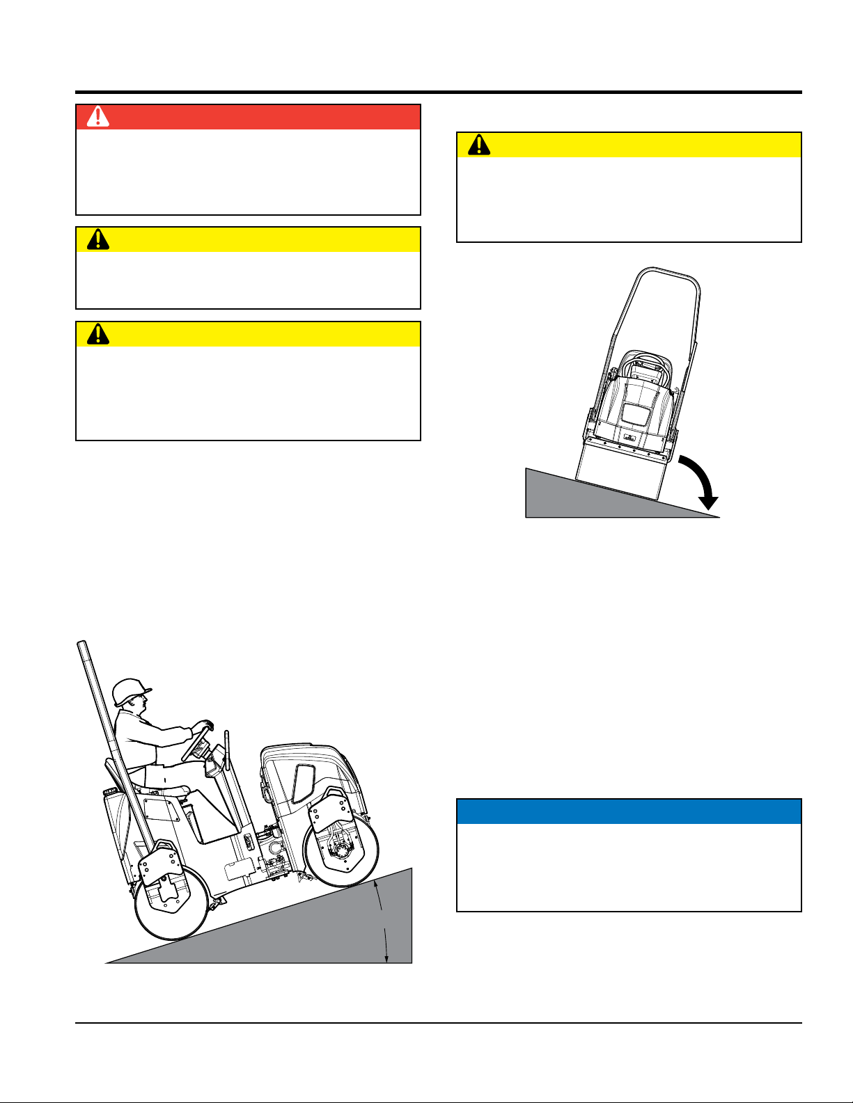
OPERATING ON SLOPES
Special care must be taken when operating the roller on
hills or slopes. There exists the possibility of serious injury
to the operator and severe damage to the roller in the event
of a roll over. ALWAYS operate the roller up and down hills
rather than from side to side. For safe operation, hillside
slopes should not exceed 14 degree (25 % grade). See
Figure 2. Always wear seat belt when operating the roller.
IMPROPER OPERATION ON SLOPES
CAUTION
NEVER operate the roller on side slopes (Figure 3). The
possibility exists that the roller could tip over (roll over),
thus causing bodily harm, even death, and serious
damage to the equipment.
SIDE TO SIDE
OPERATION
NOT
RECOMMENDED
ROLL OVER
Figure 3. Improper Operation on Slope
In the event the roller does tip over, if at all possible, try to
shut down the engine by turning the ignition key to the OFF
position. Extreme care must be taken to prevent damage
to the engine. When the roller has been tipped over, oil
from the engine crankcase can flow into the combustion
chamber, which can severely damage the engine the next
time it is started.
IMMEDIATELY after a unit has tipped over, upright the
unit as soon as possible to prevent oil from leaking into
the combustion chamber.
NOTICE
To prevent damage to the engine after a rollover, the
roller must not be started. NEVER start a roller after
a rollover. Contact your nearest authorized Multiquip
dealer for instructions or servicing.
25%
Figure 2. Recommended Slope
AR14H RIDE-ON ROLLER • OPERATION MANUAL — REV. #3 (09/06/19) — PAGE 13
Page 14
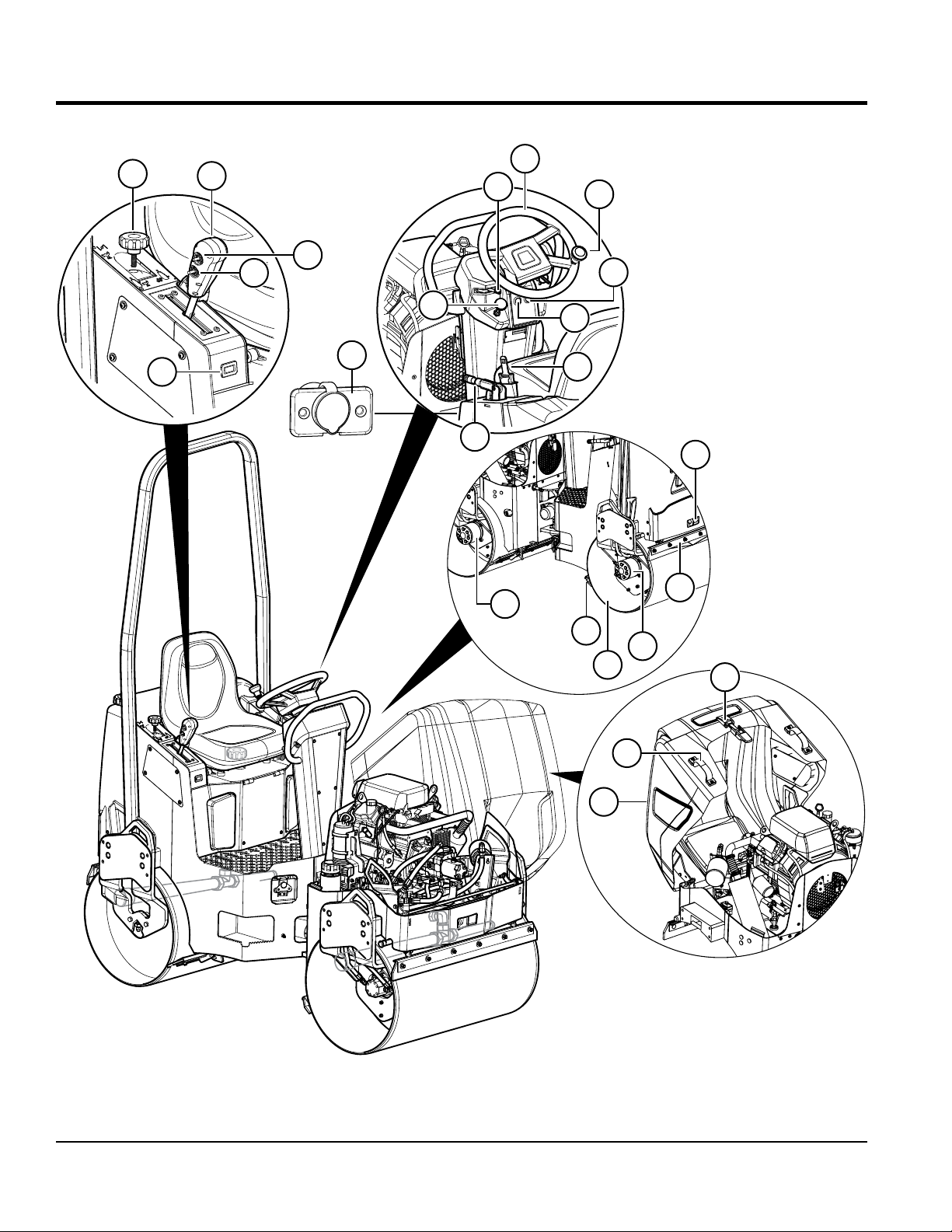
COMPONENTS
1
5
2
3
4
6
14
13
7
15
8
9
10
11
12
16
17
RIGHT SIDE
17
LEFT SIDE
15
18
21
20
19
Figure 4. Roller Components ( 1 of 3)
PAGE 14 — AR14H RIDE-ON ROLLER • OPERATION MANUAL — REV. #3 (09/06/19)
Page 15

COMPONENTS
Figure 4 shows the location of the components and controls
(1 of 3) for the AR14H compaction roller. The function of
each component or control is described below:
1. Water Volume Control Valve — This valve controls
the volume flow of water to the front and rear spray
bars. Turn the valve to the counterclockwise to increase
water flow and clockwise to decrease water flow.
2. Travel Lever — Push the lever forward to make
the roller travel in a forward direction. Pull the lever
backward to make the roller travel in a reverse direction.
Maximum travel speed is 4.8 MPH (7.7 KPH). Center
position is neutral; no travel.
3. Vibration Control Switch — Toggle switch to activate
the eccentric that will produce a vibration frequency of
4,200 vpm (vibrations per minute). Toggle switch again
to stop vibration.
4. Water Pump Switch — Activates the water pump. The
water pump indicator turns on.
5. Hour/Tachometer — Indicates the number hours the
unit has been in use when engine is off and RPM when
engine is running.
6. Choke Knob — Used in the starting of a cold engine,
or in cold weather conditions. The choke enriches the
fuel mixture.
7. Throttle Control — Slide control to the left to increase
engine rpm. Slide to the right to decrease engine rpm.
Slide all the way to the left to achieve maximum engine
rpm.
8. Steering Wheel — Use this wheel to steer the roller.
9. Steering Wheel Knob — Use this knob to move the
steering wheel with one hand.
10. Engine Oil Indicator — Lights to indicate low engine
oil level. The engine will automatically turn off. Add oil
as necessary.
11. Water Pump Indicator — Lights when the water
pump is on.
12. Seat Belt — When operating the roller, always have
the operator wear the seat belt. NEVER use the roller
without wearing a seat belt. If the seat belt becomes
worn or damaged, replace it immediately.
engage the parking brake. To release the parking brake,
push lever downward.
14. 12V Power Outlet — Charges small portable electronic
devices.
15. Hydraulic Motors — These hydraulic motors provide
forward/reverse drive for drums.
16. Tie-Down Transport Points (Front and Rear) —
Attach a chain or suitable tie-down device to these
when transporting of the roller is required.
TRANSPORT
TIE-DOWN POINT
17. Rear Drum Roller Scraper Bars (2) — Helps prevent
the buildup of material between the drum and frame.
The scraper bar is spring-loaded for easy change and
clean up. No tools are required.
18. Rear Drum — This is a 35.6-inch wide steel drum
with a diameter of 22 inches. It has beveled edges to
help prevent asphalt marring. The rear drum has a
water ballast allowing 34 gallons of water to add 292
of static force.
19. Compartment Hood — Houses the engine, hydraulic
manifold, accessory relay, hydraulic oil filter, hoses,
and hydraulic pump. To lift the compartment hood,
release the rubber bungee latch located on the front
of the hood.
20. Compartment Hood Lift Point — Place hand here
on either side of the roller then lift compartment hood.
21. Bungee Latch — Pull this rubber latch upward and
back to gain access to the engine/pump compartment.
13. Parking Brake Lever — Pull the lever upward to
AR14H RIDE-ON ROLLER • OPERATION MANUAL — REV. #3 (09/06/19) — PAGE 15
Page 16

23
COMPONENTS
25
24
26
22
29
35
RIGHT SIDE
32
27
28
290
33
34
32
30
Figure 5. Roller Components (2 of 3)
30
31
16
PAGE 16 — AR14H RIDE-ON ROLLER • OPERATION MANUAL — REV. #3 (09/06/19)
Page 17

COMPONENTS
Figure 5 shows the location of components and controls
(2 of 3) for the AR14H compaction roller. The function of
each component or control is described below:
22. Water Tank — Unscrew tethered cap and fill tank with
water. Water tank capacity is 34 gallons (130 liters).
23. Operator's Seat — A contoured seat that provides
visibility of both front and rear drum edges during
operation. NEVER start the roller unless seated in the
operator's seat. The seat has a detent that holds it in
place when lifted for refueling.
24. Cup Holder — Holds standard travel mugs.
25. Roll-Over Bar — This unit is equipped with a Roll
Over Protection System (ROPS) to protect the operator
when the roller is used on slopes.
26. Hand Rail — Grab hold of this hand rail when lifting
yourself onto the operator's platform.
27. Fuel Tank/Fuel Gauge — The fuel capacity of the fuel
tank is 9.5 gallons (36 liters). Fill with unleaded-type
gasoline. There is a gauge on top of the fuel cap to
indicate if fuel level is low. To gain access to the fuel
tank, tilt the front seat forward. Fuel tank has a spill
containment feature.
29. Lifting Points (4) — Attach a crane or suitable lifting
device to these points when lifting of the roller is
required.
30. Front Drum Roller Scraper Bars (2) — Helps prevent
the buildup of material between the drum and frame.
The scraper bar is spring-loaded for easy change and
clean up. No tools are required.
31. Front Drum — This is a 35.6-inch wide steel drum
with a diameter of 22 inches. It has beveled edges to
help prevent asphalt marring. The vibratory assembly
is built into the front drum.
32. Front and Rear Sprinkler System — Pressurized
spray bars are provided for wetting the roll for asphalt
pavement.
33. Platform Latch — Used to release platform to gain
access to the battery, water pump, water filter, and fuel
shut-off valve.
34. Foot Step — To lift yourself onto the roller's platform,
place foot into foot step, then grab hold of hand rail.
35. Rear Drum Grease Zerk Fitting — Grease this fitting
biweekly. See maintenance section of this manual.
28. Seat Adjustment Knob — Allows operator's seat to
be adjusted (slide seat forward or backward).
AR14H RIDE-ON ROLLER • OPERATION MANUAL — REV. #3 (09/06/19) — PAGE 17
Page 18

38
COMPONENTS
39
37
44
36
45
46
47
48
40
41
43
42
49
50
51
59
55
58
57
Figure 6. Roller Components (3 of 3)
57
56
52
54
53
PAGE 18 — AR14H RIDE-ON ROLLER • OPERATION MANUAL — REV. #3 (09/06/19)
Page 19

COMPONENTS
Figure 6 shows the location of components and controls
(3 of 3) for the AR14H compaction roller. The function of
each component or control is described below:
36. Battery — Provides +12VDC to the electrical system,
and is located underneath foot plate. Replace only with
recommended type battery.
37. Water Filter — Filters the water in the water pump.
38. Water Pump — Provides pressure to the water
sprinklers to allow even distribution of water on the
drums.
39. Fuel Shut-Off Valve — Stops the flow of fuel.
40. Accessory Relay — Provides the +12VDC necessary
to run the electrical accessories.
41. Fuse (10 Amp) — Povides overcurrent protection for
the water pump.
42. Fuse (30 Amp) — Provides overcurrent protection for
the starter.
43. Fuse (20 Amp) — Provides overcurrent protection for
the 12V outlet.
44. Articulating Locking Latch — Secures the front and
rear sections of the roller when lifted during transport
and maintenance.
45. Ignition Switch — With key inserted, turn clockwise
to start the engine.
46. Engine Oil Drain — Used to drain oil from the engine.
47. Engine — This unit incorporates a HONDA
GX630RHKAF, air-cooled engine rated at 20 hp at
3,200 rpm.
48. Charcoal Canister — Keeps gasoline from evaporating
into the atmosphere. The carbon in the canister absorbs
the fuel vapor.
49. Hydraulic Oil Filter — Filters return oil from the front
and rear hydraulic motors.
50. Hydraulic Pump — This unit incorporates an axial
variable displacement hydraulic piston pump.
51. Gear Pump — Controls vibration and steering.
52. Hydraulic Manifold — Aluminum block that controls
the flow of hydraulic pressure to the various hydraulic
motors and other components required to control the
roller.
53. Hydraulic Motor — This hydraulic motor controls the
rotation of the vibratory system.
54. Hydraulic Fluid Filler Port — Remove this cap to
add hydraulic fluid. Fill with type ISO 46 anti-wear
hydraulic fluid.
55. Hydraulic Oil Level Indicator — Indicates the amount
of hydraulic oil present.
56. Hydraulic Oil Drain — Used to drain used hydraulic
oil when oil replacement is necessary.
57. Steering Cylinder Grease Zerk Fitting — Grease
this fitting biweekly. See maintenance section of this
manual.
58. Steering Cylinder — Controls direction of roller.
59. Documentation Canister — Store and maintain
Operation, Parts, and Engine manuals in this container
at all times.
AR14H RIDE-ON ROLLER • OPERATION MANUAL — REV. #3 (09/06/19) — PAGE 19
Page 20

BASIC ENGINE
6
4
3
2
5
1
Figure 7. Engine Components
The engine (Figure 7) must be checked for proper
lubrication and filled with fuel prior to operation. Refer to the
manufacturer's engine manual for operation and servicing
information.
1. Oil Drain Plug — Remove to drain crankcase oil. Fill
with recommended type oil as listed in Table 4.
2. Oil Filter — Spin-on type, filters oil for contaminants.
3. Spark Plug — Provides spark to the ignition system.
Set spark plug gap to 0.6 - 0.7 mm (0.028 - 0.031 inch)
Clean spark plug once a week.
4. Lifting Hook Eye — Attach a lifting device of adequate
lifting capacity at this lifting point whenever lifting of the
engine is required.
7
4
9
8
10
5
1
5. Fuel Filter — Prevents dirt and other debris from
entering the fuel system.
6. Air Filter — Prevents dirt and other debris from
entering the fuel system. Unsnap air filter cover to gain
access to filter element.
7. Oil Filler Cap — Remove to add engine oil.
8. Oil Dipstick — Remove to check amount and condition
of oil in crankcase. Refill or replace with recommended
type oil as listed in Table 4.
9. Starter/Solenoid — Starts engine when ignition key
is rotated to the ON position.
10. Oil Cooler — Helps keep engine oil cooler for longer
engine life.
PAGE 20 — AR14H RIDE-ON ROLLER • OPERATION MANUAL — REV. #3 (09/06/19)
Page 21

INSPECTION
BEFORE STARTING
1. Read safety instructions at beginning of manual.
2. Clean the roller, removing dirt and dust, particularly
the engine cooling air inlet, carburetor and air cleaner.
3. Check the air filter for dirt and dust. If air filter is dirty,
replace air filter with a new one.
4. Check carburetor for external dirt and dust. Clean with
dry compressed air.
5. Check fastening nuts and bolts for tightness.
ENGINE OIL CHECK
1. To check the engine oil level, place the roller on secure
level ground with the engine stopped.
2. Remove the dipstick from its holder (Figure 8) and
wipe it clean.
DIPSTICK
3. Check the oil level shown on the dipstick (Figure 9).
Figure 9. Engine Oil Dipstick Level
4. If the oil level is low, remove the oil filler cap (Figure 10)
and fill to the safe operating level (max) as indicated by
the dipstick. Fill with recommended type oil as listed in
Table 4. Maximum oil capacity is 1.9 quarts (1.8 liters).
Figure 8. Engine Oil Dipstick (Removal)
Table 4. Oil Type
Season Temperature Oil Type
Summer 25°C or Higher SAE 10W-30
Spring/Fall 25°C~10°C SAE 10W-30/20
Winter 0°C or Lower SAE 10W-10
OIL FILLER CAP
Figure 10. Engine Oil Filler Port
NOTICE
The HONDA GX630 engine used on this roller has an
"Oil Alert System". This system will automatically stop
the engine in the event of low oil level. ALWAYS check
the engine oil level prior to starting the engine.
AR14H RIDE-ON ROLLER • OPERATION MANUAL — REV. #3 (09/06/19) — PAGE 21
Page 22

INSPECTION
FUEL CHECK
DANGER
Motor fuels are highly flammable and can
be dangerous if mishandled. DO NOT
smoke while refueling. DO NOT attempt
to refuel the machine if the engine is hot
or running.
1. To check the engine fuel level, place the roller on secure
level ground with the engine stopped.
2. Tilt the operator's seat (Figure 11) forward to gain
access to the fuel tank. The seat is equipped with a
latch that keeps the seat locked in place when tilted
forward.
TILT DRIVER’S SEAT
FORWARD
SEAT
3. Read the fuel gauge (Figure 12) located on top of the
filler cap to determine if fuel level is low.
Figure 12. Fuel Gauge
4. If the fuel level is low, remove the fuel filler cap and
fill with unleaded gasoline. Wipe up any spilled fuel
immediately.
5. Pay attention to the fuel tank capacity when replenishing
fuel. Refer to the fuel tank capacity listed on the
specifications table.
6. After replenishing fuel, make sure filler cap is securely
tightened to fuel tank. Return operator's seat to normal
operating position.
HYDRAULIC OIL CHECK
SEAT
LATCH
ENGAGED
Figure 11. Fuel Tank Access
FUEL FILLER
NECK
1. To check the hydraulic oil level, place the roller on
secure level ground with the engine stopped.
2. Visually inspect the hydraulic oil sight glass (Figure 13)
located on the right rear of the front drum. For normal
operation the hydraulic oil level must be below the
top and above the bottom of the sight glass. DO NOT
OVERFILL!
NORMAL
LEVEL
HYDRAULIC
OIL LEVEL
SIGHT GLASS
LOW LEVEL
ADD
HYDRAULIC
OIL
Figure 13. Hydraulic Oil Sightglass
PAGE 22 — AR14H RIDE-ON ROLLER • OPERATION MANUAL — REV. #3 (09/06/19)
Page 23

INSPECTION
3. If the hydraulic oil level is low, remove the hydraulic
oil cap (Figure 14) and fill with type ISO 46 anti-wear
type hydraulic oil to the recommended operating level.
HYDRAULIC
OIL CAP
HYDRAULIC
OIL
HYDRAULIC OIL
FILLER NECK
Figure 14. Hydraulic Oil Reservoir Filler Port
BATTERY CHECK
ALWAYS be sure that the battery cables are properly
connected to the battery terminals as shown in Figure 16.
Generally the RED cable will be connected to the positive
terminal of the battery, and the BLACK cable will be
connected to the negative terminal of the battery.
POSITIVE
RED
NEGATIVE
BLACK
WATER TANK CHECK
1. Visually inspect the water level in the water tank. When
the water level is low, water needs to be added to the
water tank (Figure 15). Total tank capacity is 34 gallons
(130 liters.)
NOTICE
During freezing weather conditions, drain water from
system to prevent component damage.
WATER TANK
CAP
WATER TANK
Figure 16. Battery
NOTICE
If the battery cables are connected incorrectly, electrical
damage will occur causing damage to the roller's
electrical circuits. Pay close attention to the polarity of
the battery when connecting the battery.
Figure 15. Water Tank
AR14H RIDE-ON ROLLER • OPERATION MANUAL — REV. #3 (09/06/19) — PAGE 23
Page 24

OPERATION
STARTUP
NOTICE
DO NOT attempt to operate the roller until the Safety,
General Information and Inspection sections have been
read and understood.
1. Place your foot into the roller's foot step, grab hold of
the hand rail located on the steering console, and lift
yourself onto the platform.
2. Sit down in the operator's seat and adjust the seat
for a comfortable position, then fasten the seat belt
(Figure 17) around your waist. NEVER operate the
roller without the seat belt being fastened. Serious
injury could occur if the seat belt is not used.
FASTEN
SEAT BELT
5. In cold weather, start the roller with the choke fully
closed. In warm weather or when the engine is
warm, the roller can be started with choke halfway or
completely open.
PULL UP
TO CLOSE
PUSH DOWN
TO OPEN
Figure 17. Securing Seat Belt
3. Before starting engine, make sure the immediate area
is free of obstructions and debris that may lay in the
roller's path.
4. Make sure that the roller's travel lever (Figure 18) is
placed in the neutral position.
NEUTRAL
Figure 19. Choke Knob
6. Slide the throttle control (Figure 20) all the way to the
left for maximum rpm.
THROTTLE
CONTROL LEVER
FAST
SLOW
Figure 18. Travel Lever (Neutral)
Figure 20. Throttle Control
PAGE 24 — AR14H RIDE-ON ROLLER • OPERATION MANUAL — REV. #3 (09/06/19)
Page 25

OPERATION
7. Insert the ignition key into the ignition (Figure 21), then
turn and hold the key in the clockwise position until the
engine starts, release key.
OFF
ON
START
IGNITION
KEY
Figure 21. Ignition Switch
8. If the engine does not start, repeat steps 1 through 7
or consult the troubleshooting guide contained in this
manual.
9. Depending on weather conditions, let the engine warm
for 3 to 5 minutes before using roller. Check for fuel
and oil leaks, and noises that would associate with a
loose guard and/or covers.
10. If necessary, return the choke knob to the full OPEN
position.
NOTICE
The CLOSED position of the choke knob enriches the
fuel mixture for starting a COLD engine. The OPEN
position provides the correct fuel mixture for normal
operation after starting, and for restarting a warm
engine.
PARKING BRAKE
1. To release the parking brake, push the parking brake
lever all the way down (Figure 22).
LOCK POSITION
PULL UPWARD
TRAVEL LEVER
1. To make the roller move in a forward direction, move
the travel lever forward as shown in Figure 23.
FORWARD
POSITION
NEUTRAL
POSITION
REVERSE
POSITION
Figure 23. Travel Lever (Moving)
2. Remember the speed of the roller is directly proportional
to the amount of pressure being applied to the lever
in each direction. Travel speed is between 0 and 4.8
mph (7.2 kph).
NOTICE
ALWAYS allow the roller to come to a complete stop
before changing the direction of travel. Changing
directions before the roller comes to a complete stop
will result in excessive force being applied to the
transmission and drive system, which will reduce the
service life of the system.
3. Try maneuvering the roller a few times to get familiar
with the handling. Also place the travel lever in the
opposite direction to get acquainted with driving in
reverse.
4. Make sure that the roller comes to a complete stop
(neutral) before placing the travel lever in either a
forward or reverse position.
RELEASE POSITION
PUSH DOWN
Figure 22. Parking Brake
AR14H RIDE-ON ROLLER • OPERATION MANUAL — REV. #3 (09/06/19) — PAGE 25
Page 26

OPERATION
VIBRATION BUTTON
1. To begin the vibratory action, toggle the vibratory switch
located on the right side of the travel lever as shown
in Figure 24. This will generate 3,400 lbf. (15.1 kN) of
centrifugal force at a frequency of 4200 vpm (vibrations
per minute) to the front drum.
VIBRATION
SWITCH
Figure 24. Vibration Toggle Switch
2. A water volume control valve for the sprinklers is
provided. This control valve (Figure 26) is located
right below the travel lever. The valve controls the
water supply simultaneously to the front and rear drum
spray bars.
a. To increase water volume, turn the control valve
counterclockwise.
b. To decrease water volume, turn the control valve
clockwise.
2. To stop the vibratory action, toggle the vibratory switch
again.
WATER PUMP AND VOLUME CONTROL VALVE
When wetting of a surface is required, perform the following
procedure.
1. Turn on the water pump switch (Figure 25) to activate
the water pump. The water pump indicator will light.
WATER
PUMP
SWITCH
WATER VOLUME
CONTROL VALVE
Figure 26. Water Volume Control Valve
Figure 25. Water Pump Switch
PAGE 26 — AR14H RIDE-ON ROLLER • OPERATION MANUAL — REV. #3 (09/06/19)
Page 27

Perform roller maintenance as indicated by Figure 27 and Table 5.
Yearly
6 Months
3 Months
Bi-Weekly
Weekly
Daily
3
2
MAINTENANCE
1
2
3
4
5
6
7
8
9
10
11
12
13
5
6
7
6
10
12
11
10
5
6
7
6
1
4
9
8
13
Figure 27. Roller Maintenance Schedule
Table 5. Roller Maintenance Schedule
Daily Notes
Engine Oil Level See Table 4
Water Tank Level
Fuel Level
Hydraulic Oil Level Use ISO 46 Type Hydraulic Oil
Sprinkler System
Scraper Replace when badly worn
Drums (Front/Rear)
Weekly
Air Filter Replace paper element once a year.
Battery Electrolyte Level
Bi Weekly
Grease Zerk Fittings Use Type Alvania #2 or equivalent -3 shots max. DO NOT overgrease
3 Months
Hydraulic Oil Filter (Return) Replace with same type filter.
6 Months
Engine Oil Filter After first 20 hrs, change oil filter every 6 months or 100 hrs.
Yearly
Hydraulic Oil Use ISO 46 Type Hydraulic Oil
AR14H RIDE-ON ROLLER • OPERATION MANUAL — REV. #3 (09/06/19) — PAGE 27
Page 28

MAINTENANCE
HYDRAULIC OIL SYSTEM
The hydraulic system consists of a two-pump stack directly
coupled to the engine. A hydraulic valve block (manifold)
is provided for quick and easy testing and troubleshooting.
Hydraulic oil is filtered by a screen filter located in the tank
filler neck, a 40 micron suction filter located in the tank, and
a 10 micron return filter, with cold oil bypass valve located
in the return circuit.
It is recommended that ISO 46 type hydraulic oil or
equivalent be used when adding or replacing the hydraulic
oil is required.
DO NOT USE MULTI-VISCOSITY OIL. Clean oil is a
very important part of proper hydraulic system operation.
Hydraulic oil is not only used to transfer power; it also
lubricates and cools the system components. Keeping
the hydraulic system clean can help reduce costly repairs.
The hydraulic oil level sight glass is located on the right
rear of the front drum, below the engine compartment. This
level should be checked daily. Oil must be below the top and
above the bottom of the sight glass. DO NOT OVERFILL!
Care should be taken to clean the filler cap before adding oil
to the system. If hydraulic oil has to be added, the machine
should be inspected for leaks.
2. Remove the hydraulic oil drain plug (Figure 28) and
drain the hydraulic oil. Dispose of the used oil in an
environmentally friendly manner. Replace the drain
plug and tighten.
HYDRAULIC OIL
RETURN FILTER
HYDRAULIC OIL
CAP/FILLER PORT
HYDRAULIC OIL
DRAIN PLUG
Figure 28. Hydraulic Filter Locations
The suction filter (Figure 28) is located inside the hydraulic
tank. This filter is attached to the fitting connected to the
hydraulic pump suction hose.
The return filter (Figure 28) is located at the front of the
engine compartment. Replace both filters according to the
Table 5.
CAUTION
DO NOT open hydraulic lines or loosen hydraulic fittings
while engine is running! Hydraulic fluid under pressure
can penetrate the skin, blind, cause burns or create
other potentially dangerous hazards follow all safety
instructions as described throughout this manual.
CHANGING HYDRAULIC OIL AND FILTERS
1. Park the roller on a clean flat work area and set the
parking brake.
3. Remove the return filter and install a new filter. Dispose
of the used filter in an environmentally friendly manner.
4. Disconnect the suction hose and remove the fitting from
the tank. Replace the suction filter. Dispose of the used
filter in an environmentally friendly manner. Replace
the fitting and reconnect the suction hose.
FREEWHEEL ENGAGEMENT VALVE
NOTICE
The freewheel engagement valve (towing) is only for
emergency use. DO NOT move roller over 2 MPH or
long distances as hydraulic system component failure
could result.
This hydraulic system has a freewheel engagement valve
allowing hydraulic oil to be bypassed. Open (turn allen
wrench counterclockwise) this valve (Figure 29) to engage
the freewheel capability of the roller. When the valve is fully
opened, ports A and B are allowed to connect, bypassing
the oil to and from the drum drive motors.
PAGE 28 — AR14H RIDE-ON ROLLER • OPERATION MANUAL — REV. #3 (09/06/19)
Page 29

MAINTENANCE
ALLEN
WRENCH
OPEN
CLOSED
FREEWHEEL
ENGAGEMENT
VA LV E
Figure 29. Freewheel Engagement Valve
Remember the freewheel engagement valve should only
be used in emergencies when the roller cannot be driven
due to engine or hydraulic system problems.
When towing of the roller has been completed, this
valve must be closed (turn allen wrench fully clockwise)
completely and the lock nut set. Failure to close this valve
completely will result in low power, improper speed, and
excessive hydraulic oil temperature.
DRUM DRIVE
VIBRATION AND STEERING
The vibration and steering system is an open loop circuit
operated by a gear type pump. Separate relief valves control
each circuit. This system consist of the gear pump, relief
valves, electric vibration control valve, vibration drive motor,
steering valve, and steering cylinder.
The vibration circuit is controlled by an electric control
valve located on the valve block (manifold). This valve is
controlled by the toggle switch mounted on the travel lever.
High-pressure oil is supplied by the pump to the valve
block (port P) and is directed to the electric control valve.
When the switch is in the “OFF” position, this valve is open
allowing oil to go to the steering valve, without driving the
vibration motor.
When the switch is in the “ON” position, the electric control
valve closes and oil is directed out of port 1 to the vibration
motor. Return oil from the motor returns to the valve block
via port 2 and is directed to the steering valve.
Steering is controlled by a steering valve and cylinder.
The steering wheel is direct coupled to the steering valve
controlling the oil flow to the cylinder. Oil supplied from the
vibration circuit is directed to port 3 which connects to port
P of the steering valve. When steering is not being used,
oil passes out of port T of the valve block and returns to
the hydraulic tank. When the steering wheel is operated,
the steering valve closes and oil is directed to ports L or R
to extend or retract the steering cylinder.
The drum drive circuit is a series, closed loop system
consisting of a hydrostatic pump, two relief valves, a
freewheel engagement valve, and front and rear drum
drive motors.
The hydrostatic pump is manually controlled by a cable
connected to the forward/reverse travel lever located on
the right side of the operator seat. When the travel lever
is placed in forward, high-pressure oil is supplied by the
hydrostatic pump to the valve block (port A). The valve
block (manifold) directs this high-pressure oil to the front
and rear drum drive motors. Return oil from the motors is
returned to the valve block (port B) and is returned to the
suction side of the hydrostatic pump.
With the travel lever in reverse position, oil will flow in the
opposite direction (port B becomes high-pressure and port
A becomes suction).
AR14H RIDE-ON ROLLER • OPERATION MANUAL — REV. #3 (09/06/19) — PAGE 29
Page 30

MAINTENANCE
RUBBER SCRAPER MAT
Rubber scraper mats have been provided for the cleaning of
the front and rear drums. Adjust the scraper mats as close
as possible to the drums, using the slotted holes (Figure 30)
provided. Replace these rubber mats when they become
badly worn. The scraper bars are spring-loaded for easy
change-out of rubber mats.
NOTICE
In order for the front scraper bar to lock in place, for
easy scraper change, the springs on the inside of the
engine cover must be removed.
SPRING (4)
2. Check hydraulic oil level by viewing the hydraulic oil
sight glass. The hydraulic oil level must be below the
top and above the bottom of the sight glass. DO NOT
OVERFILL!
3. Adjust engine RPM (3,250 ± 50 RPM).
4. Let engine run for 5 to 10 minutes, this will bring the
hydraulic oil operating temperature to a minimum of
135° F.
5. Check and repair all hydraulic leaks.
6. On the manifold block, install a 5,000 psi pressure
gauge (Figure 31) to the forward pressure quick
disconnect test port 2.
7. Run engine at full throttle.
8. Move the travel lever to the forward position. MAKE
SURE FRONT AND REAR DRUMS DO NOT SPIN.
9. Read the pressure gauge. The relief pressure (roller
drums blocked) will read 2,900 ± 145 psi. Under normal
operating conditions this pressure will read 400-600 psi.
ROLLER
RUBBER
SCRAPPER
RUBBER
SCRAPPER
Figure 30. Scraper Bar Adjustment
FORWARD/REVERSE HYDRAULIC PRESSURE
TEST
1. Park the machine on a solid flat surface and stop the
engine. Set the parking brake and block the front drum
securely.
10. Return the travel lever to the neutral position and stop
the engine.
11. Install the pressure gauge into the reverse quick
disconnect port 3 and repeat the above procedures.
The relief pressure reading for the reverse test port 3
will be the same (2,900 psi). Again normal operation
pressure for the reverse port will be 400-600 psi.
12. Normal operating pressures are based on the machine
traveling on level, firm surface. The operating pressures
will increase significantly when traveling uphill.
VIBRATION CIRCUIT PRESSURE TEST
1. Place the front drum on soil, gravel, or a heavy rubber
mat. DO NOT ACTIVATE VIBRATION FEATURE ON
CONCRETE OR HARD SURFACE!
2. On the manifold block install a 5,000 psi pressure
gauge to quick disconnect test port 1.
3. Start the engine and run at full throttle.
4. To start the vibration, toggle the vibration switch on
the travel lever. Under normal operating conditions this
pressure will range between 900-1,500 psi.
PAGE 30 — AR14H RIDE-ON ROLLER • OPERATION MANUAL — REV. #3 (09/06/19)
Page 31

MAINTENANCE
NOTICE
Vibration relief pressure is hard to read accurately using
this test. It may be necessary to disconnect the pressure
line to the vibration drive motor. Plug this line and retest,
pressure will be exact relief pressure. DO NOT perform
this test for a long period of time — damage could occur.
STEERING PRESSURE TEST
1. On the manifold block, install a 5,000 psi pressure
gauge into quick disconnect test port 1 (Figure 31).
2. Start the engine and run at full throttle.
3. Turn the steering wheel to the left or right (maximum)
and hold. Read the steering relief pressure. The relief
pressure reading for the steering test port 1 will be 700
psi. Again, under normal operating conditions, pressure
for the steering port will be between 200-400 psi.
4. If maximum pressure cannot be reached, plug the
steering cylinder pressure hoses and retest. If pressure
is correct, the steering cylinder is leaking. DO NOT
ACTIVATE THE VIBRATION FUNCTION WHILE
PERFORMING THIS TEST!
STEERING RELIEF VALVE PRESSURE ADJUSTMENT
To adjust the relief valve steering pressure perform the
following:
1. Insert an 8 mm allen wrench into steering relief port 4
(Figure 36) on the manifold block.
8 MM ALLEN
WRENCH
STEERING
RELIEF
VALVE
(PORT 4)
MANIFOLD
BOLD
8 MM ALLEN
WRENCH
ADJUSTMENT
SCREW
VIBRATORY
RELIEF
VALVE
(PORT 5)
MANIFOLD
BLOCK
Figure 31. Manifold Test Ports
TEST
PORT 2
TEST
PORT 1
TEST
PORT 3
5000 PSI
PRESSURE
GAUGE
2000
3000
1000
200
150
4000
100
250
50
300
bar
5000
psi
WIKA
Figure 32. Steering and Vibration Relief Valves
2. On the manifold, connect at 5,000 psi pressure gauge
into quick disconnect test port 1.
3. Start the engine and run at full throttle.
4. Turn the steering wheel to the left or right (maximum)
and hold. Read the steering relief pressure. The relief
pressure reading for the steering test port 1 will should
be 700 psi.
5. If the steering relief pressure is not 700 psi, using the
allen wrench adjust the pressure at port 4 until the
pressure gauge reads 500 psi.
AR14H RIDE-ON ROLLER • OPERATION MANUAL — REV. #3 (09/06/19) — PAGE 31
Page 32

MAINTENANCE
VIBRATION RELIEF VALVE PRESSURE
ADJUSTMENT
1. Insert an 8 mm allen wrench into steering relief port 5
(Figure 32) on the manifold block.
2. On the manifold block, insert a 5,000 psi pressure
gauge into quick disconnect test port 1.
3. Start the engine and run at full throttle.
4. To start the vibration, toggle the vibration switch located
on the travel lever. The relief pressure should read
900 - 1,500 psi.
5. If the vibration relief pressure is not 900 - 1,500 psi,
using the allen wrench, adjust the pressure at port 5
until the pressure gauge reads correctly.
REMOVING AND REPLACING HYDROSTATIC PUMP
1. Set the parking brake.
2. Disconnect the battery.
3. Clean the pump and all connections.
4. Mark and disconnect all hoses and lines from the pump.
5. Disconnect the forward / reverse control cable.
6. Disconnect the pump support bracket.
7. Remove the engine mounting bolts.
REMOVING AND REPLACING VIBRATION/
STEERING PUMP
1. Remove the hydrostatic pump as per preceding
instructions.
2. Remove all hoses and lines.
3. Disconnect the vibration / steering pump and remove.
4. Repair or replace pump as required.
5. Install the pump in the reverse order of removal, using
Locktite 271 on all mounting bolts and nuts.
6. Test operation. Test and adjust the forward and reverse
pressure relief valves as required. Adjust the forward/
reverse control cable. Test and adjust the vibration and
steering pressure relief valves as required.
DRUMS AND MAIN FRAME
1. The front drum is designed to apply vibration and
compaction force to the operating surface for
compaction. This vibration and compaction force is
produced when the vibrator shaft is rotated. Maximum
efficiency is achieved only when the engine is operated
at full throttle.
2. A single drive motor is mounted on the left side of the
drum and is shock mounted. This type of drive motor
is designed for maximum torque and power.
8. Elevate the pump and engine assembly using a proper
lifting device.
9. Disconnect and remove the hydrostatic pump assembly.
10. Repair or replace the hydrostatic pump as required.
11. Install the hydrostatic pump in the reverse order of
removal, using Locktite 271 on all mounting bolts and
nuts.
12. Test operation. Test and adjust the forward and reverse
relief pressures as required. Adjust the forward/reverse
control cable.
PAGE 32 — AR14H RIDE-ON ROLLER • OPERATION MANUAL — REV. #3 (09/06/19)
3. The vibrator is driven by a gear motor coupled to the
vibrator shaft. The vibrator assembly rotates inside of a
sealed housing containing oil to lubricate the bearings.
This side of the drum is also shock mounted.
FRONT AND REAR DRUM DISASSEMBLY
Refer to Figure 33, Figure 34, Figure 35, and Figure 36
for the disassembly of the front and rear drums to access
different components that may need to be replaced.
Page 33

Figure 33 shows the removal of the exciter assembly from
the right side of the front drum.
STEP 1
MAINTENANCE
STEP 4
COVER
STEP 2
1. JACK FRAME UP SLIGHTLY AT ARTICULATION
JOINT.
2. REMOVE 4 ALLEN HEAD SCREWS HOLDING THE
COVER OF THE DRUM SUPPORT PLATE AND
REMOVE COVER.
5. REMOVE 6 NUTS SECURING THE 3
SHOCK MOUNTS TO THE SUPPORT
PLATE. REMOVE THE SUPPORT
PLATE.
NOTE: MOTOR OR SHOCK MOUNTS
CAN BE REMOVED AND REPLACED
AT THIS POINT.
6. REMOVE THE 6 BOLTS SECURING
THE EXCITER PLATE TO THE
DRUM WALL.
7. PULL EXCITER ASSEMBLY TO
REMOVE FROM DRUM INTERIOR.
STEP 3
DRUM
SUPPORT
PLATE
3. MARK AND DISCONNECT HOSES FROM MOTOR
AND MANIFOLD.
4. REMOVE FOUR BOLTS FROM DRUM SUPPORT
PLATE. (BOLTS MAY NEED TO BE HEATED TO
REMOVE).
FRONT DRUM
STEP 7
STEP 6
EXCITER
ASSEMBLY
EXCITER PLATE
MOTOR
8. REVERSE PROCEDURE TO
INSTALL EXCITER ASSEMBLY
AND REASSEMBLE DRUM. USE
LOCKTITE 271 ON ALL BOLT
THREADS.
Figure 33. Exciter Assembly Removal/Installation (Front Drum - Right Side)
AR14H RIDE-ON ROLLER • OPERATION MANUAL — REV. #3 (09/06/19) — PAGE 33
STEP 5
DRUM
WALL
SHOCK MOUNTS
Page 34

STEP 6
STEP 4
SHOCK
MOUNT
MOTOR
DRUM
SUPPORT
PLATE
FRONT DRUM
Figure 34 shows the removal of the motor and shock
mounts from the left side of the front drum.
STEP 1
STEP 2
COVER
MAINTENANCE
STEP 3
STEP 5
DRUM
SUPPORT
PLATE
1. JACK FRAME UP SLIGHTLY AT ARTICULATION
JOINT.
2. REMOVE 4 ALLEN HEAD SCREWS HOLDING THE
COVER OF THE DRUM SUPPORT PLATE AND
REMOVE COVER.
3. REMOVE FOUR BOLTS FROM DRUM SUPPORT
PLATE. (BOLTS MAY NEED TO BE HEATED TO
REMOVE).
4. REMOVE 4 BOLTS SECURING MOTOR TO THE
SUPPORT PLATE.
5. MARK AND DISCONNECT HOSES
FROM MOTOR AND MANIFOLD.
REMOVE MOTOR AS NECESSARY.
6. REMOVE AND REPLACE SHOCK
MOUNTS AS NECESSARY.
7. REVERSE PROCEDURE TO INSTALL
MOTOR OR SHOCK MOUNTS.
REASSEMBLE DRUM. USE LOCKTITE
271 ON ALL BOLT THREADS.
Figure 34. Motor and Shock Mounts Removal/Installation (Front Drum - Left Side)
PAGE 34 — AR14H RIDE-ON ROLLER • OPERATION MANUAL — REV. #3 (09/06/19)
Page 35

Figure 35 shows the removal of the bearing from the right
side of the rear drum.
STEP 2
MAINTENANCE
COVER
DRUM
SUPPORT
STEP 3
4. REMOVE THE BEARING.
5. REVERSE PROCEDURE TO INSTALL BEARING AND
REASSEMBLE DRUM. USE LOCKTITE 271 ON ALL
BOLT THREADS.
PLATE
STEP 1
1. JACK FRAME UP SLIGHTLY AT ARTICULATION
JOINT.
2. REMOVE 4 ALLEN HEAD SCREWS HOLDING THE
COVER OF THE DRUM SUPPORT PLATE AND
REMOVE COVER.
3. REMOVE FOUR BOLTS FROM DRUM SUPPORT
PLATE. (BOLTS MAY NEED TO BE HEATED TO
REMOVE).
REAR DRUM
STEP 4
BEARING
DRUM
SUPPORT
PLATE
Figure 35. Bearing Removal/Installation (Rear Drum - Right Side)
AR14H RIDE-ON ROLLER • OPERATION MANUAL — REV. #3 (09/06/19) — PAGE 35
Page 36

STEP 3
Figure 36 shows the removal of the motor from the left side
of the rear drum.
DRUM
SUPPORT
PLATE
STEP 6
MAINTENANCE
COVER
STEP 2
STEP 7
MOTOR
STEP 5
STEP 1
1. JACK FRAME UP SLIGHTLY AT ARTICULATION
JOINT.
2. REMOVE 4 ALLEN HEAD SCREWS HOLDING THE
COVER OF THE DRUM SUPPORT PLATE AND
REMOVE COVER.
3. REMOVE FOUR BOLTS FROM DRUM SUPPORT
PLATE. (BOLTS MAY NEED TO BE HEATED TO
REMOVE).
4. REMOVE 2 SMALL NUTS FROM THE LOWER PART
OF THE DRUM SUPPORT PLATE.
5. REMOVE LARGE NUT FROM THE LOWER PART OF
THE DRUM SUPPORT PLATE.
Figure 36. Motor Removal/Installation (Rear Drum - Left Side)
STEP 4
STEP 8
6. REMOVE 2 BOLTS FROM THE LOWER PART OF
THE DRUM SUPPORT PLATE. REMOVE DRUM
SUPPORT PLATE.
7. MARK AND DISCONNECT HOSES FROM MOTOR
AND MANIFOLD.
8. REMOVE FOUR BOLTS SECURING MOTOR TO THE
DRUM SUPPORT PLATEPLATE. REMOVE MOTOR.
9. REVERSE PROCEDURE TO INSTALL MOTOR AND
REASSEMBLE DRUM. USE LOCKTITE 271 ON ALL
BOLT THREADS.
PAGE 36 — AR14H RIDE-ON ROLLER • OPERATION MANUAL — REV. #3 (09/06/19)
Page 37

MAINTENANCE
ALTERNATOR/REGULATOR
This roller is equipped with a 20-amp charging system. This
system uses three charge coils connected in parallel. The
windings of each coil are wound with heavy-duty insulated
wire and are further protected by insulating material for long
life. A voltage regulator is provided to control the amount
of charge voltage being delivered to the 12 volt electrical
system. For servicing this charging system, contact your
Honda dealer.
NEUTRAL SAFETY SWITCH
The travel lever is provided with a neutral safety switch
(Figure 37) that prevents the engine from starting when
the lever is in the forward or reverse drive position. Lever
must be placed in the neutral position in order for the starter
to function.
TRAVEL LEVER
To test the vibration solenoid, turn the ignition switch on.
Check for proper supply voltage and ground. If proper
voltage and ground are present, check the solenoid for
continuity. If no continuity, replace the solenoid coil. If
continuity is present, place your hand on the solenoid and
turn the switch to the ON position; movement should be felt.
DO NOT START THE ENGINE FOR THIS TEST.
Figure 38. Vibration Solenoid
BATTERY
Mishandling of the battery shortens the service life of the
battery and adds to maintenance cost. When handling the
battery do the following:
NEUTRAL SAFETY
SWITCH
WHITE
GREEN
Figure 37. Safety Switch
To check this switch, remove the panel located below and
to the rear of the floor. This switch is mounted to the lower
forward/ reverse lever mechanism. Disconnect the white
and green wires. Place the lever in neutral and test for
continuity. Place the lever in forward or reverse; no continuity
should be present. Repair or replace as required.
VIBRATOR SOLENOID
The vibrator solenoid (Figure 38) is located in the manifold
valve block and is controlled by the vibration switch located
on top of the travel lever. This solenoid controls the vibration
control valve which supplies hydraulic oil to the vibration
drive motor.
Be careful not to let the battery electrolyte come in
contact with your body or clothing.
Always wear eye protection and rubber gloves, since
the battery contains sulfuric acid which burns skin and
eats through clothing.
Check the battery regularly and make sure that each
electrolyte level is to the bottom of the vent well
(Figure 42). If necessary, add only distilled water in a
well-ventilated area.
Figure 39. Battery Fluid Levels
AR14H RIDE-ON ROLLER • OPERATION MANUAL — REV. #3 (09/06/19) — PAGE 37
Page 38

PREPARATION FOR LONG-TERM STORAGE
ROLLER STORAGE
For storage of the roller for over 30 days, the following is
recommended:
1. Drain the fuel tank completely, or add STA-BIL to the
fuel.
2. Run the engine until the fuel in the injection system is
completely consumed.
3. Completely drain used oil from the engine crankcase
and fill with fresh clean oil, then follow the procedures
described in the engine manual for engine storage.
4. Drain water tank.
5. Clean the entire roller and engine compartment.
6. Remove battery and store it in cool dry place.
7. Cover the roller and place it a clean dry area, that is
protected from harsh elements.
8. Remove ignition key, and store in a safe place.
PAGE 38 — AR14H RIDE-ON ROLLER • OPERATION MANUAL — REV. #3 (09/06/19)
Page 39

MANIFOLD TEST PORTS
AR14H RIDE-ON ROLLER • OPERATION MANUAL — REV. #3 (09/06/19) — PAGE 39
Page 40

MAIN
AXIAL PUMP
T1 T2
HYDRAULIC SYSTEM DIAGRAM
EXCITER
RELIEF VALVE
2000 PSI
MANIFOLD
P
STEERING
RELIEF VALVE
TEST
G1
M
W
EXCITER
VALVE
700 PSI
INTERNAL DRIVE PUMP
RELIEF VALVES
2900 ± 145 PSI
P1
S1
TEST
G2
TEST
G3
G
W
X
A
W
W
B
M
TOW
VALV E
T
1
2
P
3
4
T
STEERING VALV E
GEAR PUMP
STEERING & VIBRATION
A
FRONT
DRIVE
MOTOR
W
W
VIBRATION
EXCITER
MOTOR
SERIES
DRIVE
L
R
DRIVE
MOTOR
STEERING
CYLINDER
B
REAR
10 MICRON
SUCTION
FILTER
100 PSI
M
RETURN LINE FILTER
ASSEMBLY
W
FILTER BYPASS
25 PSI
PAGE 40 — AR14H RIDE-ON ROLLER • OPERATION MANUAL — REV. #3 (09/06/19)
Page 41

BATTERY
30 AMP
F2
RED 14 AWG
+12 VDC
GND
WATER
PUMP ON
LAMP
RED
14 AWG
BLK
14 AWG
WHT
OIL ALARM
LAMP
OIL
SENSOR
RED14
AWG
BLK
BLK14
AWG
WHT
BLK
1
2
BLK/WHT
WHT
3
BLK
4
5
6
GRN
BLK/YEL
1
2
3
4
5
6
RED 14 AWG
BRN
GND
SPLICE
FUEL CUT-OFF
SOLENOID
BLK/YEL
YEL
GRN
GRN
GND
IGNITION
COIL (RIGHT)
CHASSIS
GND.
OIL LEVEL
SWITCH
BLK
IGNITION
COIL (LEFT)
CHASSIS
GND.
YEL
YEL
BLK
+12VDC OUT IG.
GND
BLK
14 AWG
+12VDC
OUTLET
+12VDC INPUT IG.
RED
RED
14 AWG
HOUR METER
BLK
14 AWG
WHT10AWG
26 AMP
CHARGE COIL
WHT
BLUE
GRAY
SPLICE
CONNECTOR
GR
CHASSIS
GND
BLK
SPLICE
WHT/BLU
VOLTAGE
REGULATOR
RED 14 AWG
NC
BLK
14 AWG
+12VDC
YEL
BRN 14 AWG
+12VDC
TRAVEL LEVER
NEUTRAL SAFETY
SWITCH
WHITE
GREEN
VIBRATION
SWITCH
WATER PUMP
SWITCH
IGNITION
SWITCH
5
POSITION
1. OFF
2. RUN
3. START
WHT + BLK/YEL (+12VDC)
CIRCUIT“MAKE”
WHT + BLK/WHT (+12VDC)
IGNITION SWITCH COMBINATION
BLK + GRN (GND.)
PIN NO.
2 + 6
3 + 5
1 + 2
P1 P2
REAR
VIEW
1
2
3
4
5
6
P2
REAR
VIEW
1
4
4
5
6
CHASSIS
GND
YEL 18 AWG
1
FUSE AND RELAY
LOCATOR
5
P1
4
5
6
1
2
3
F1
F2
F3
K1
SAFETY SWITCH
NEUTRAL POSITION
GRN
VIBRATION
SWITCH
5
WHT
WATER PUMP
SWITCH
5
RED
REVERSE
ALARM
SWITCH
RED
BACK-UP
ALARM
2
(OPTION)
WHT
6
6
GRN
BLK
CHASSIS
GND.
YEL
YEL
BLK
BLU 14 AWG
RED
SPLICE
F1
20 AMP
YEL
B (BATT. )
85
10 AMP
K1
86
BLK
GND
F3
WATER
PUMP
30
YEL
BLUE 14 AWG
BLK 14 AWG
K1-NO
WIRING DIAGRAM
GND
87
VIBRATION
SOLENOID
WHT18AWG
HYDRAULIC
VALVE BLOCK
CHASSIS
GND.
NOTES:
1
2
3
4
5
6
AR14H RIDE-ON ROLLER • OPERATION MANUAL — REV. #3 (09/06/19) — PAGE 41
GROUND TO STOP ENGINE, (OIL SWITCH).
AUDIBLE ALARM ORDER AS OPTION.
LOCATED INSIDE STEERING COLUMN.
LOCATED UNDERNEATH FOOT PLATFORM.
LOCATED IN ENGINE COMPARTMENT.
GROUND TO START ENGINE, (IGNITION SWITCH).
Page 42

TROUBLESHOOTING
Troubleshooting (Roller)
SYMPTOM POSSIBLE PROBLEM SOLUTION
Low Vibration
No Vibration
Slow Steering
Steers Slow in One Direction Defective steering cylinder?
Slow Forward/Reverse
Speed
Low engine RPM? Check and adjust engine speed.
Low hydraulic pressure? Check and adjust hydraulic pressure.
No voltage to 12 volt solenoid?
No oil pressure?
Broken motor coupler? Replace coupler.
Low hydraulic pressure?
Steering column connector? Inspect bearings and grease if necessary.
Defective steering cylinder? Check seals, replace if necessary.
Low hydraulic pressure?
Rubber scrapper adjustment incorrect?
Rubber shock mount loose?
Check vibration switch, check coil for
continuity.
Check for proper oil pressure or defective
relief valve.
Check pressure for possible
contaminated or defective relief cartridge.
Inspect cylinder for contamination or cut
seals. Replace if necessary.
Check pressure, low oil, or contaminated/
defective relief valve cartridge.
Check for proper adjustment against
drum.
Inspect for broken mount, replace if
necessary.
Main Hydraulic Pressure
Low
Free wheel valve "open"? Close valve.
Speed control cable out of adjustment? Inspect cable and adjust if necessary.
Incorrect engine speed? Adjust engine speed to correct speed.
Rubber shock mounts defective? Inspect for sheared rubber mounts.
PAGE 42 — AR14H RIDE-ON ROLLER • OPERATION MANUAL — REV. #3 (09/06/19)
Page 43

Symptom Possible Problem Solution
Diffi cult to start, fuel is available, but no spark at
spark plug.
Diffi cult to start, fuel is available, and spark is
present at the spark plug.
Diffi cult to start, fuel is available, spark is
present and compression is normal.
Diffi cult to start, fuel is available, spark is
present and compression is low.
No fuel present at carburetor.
TROUBLESHOOTING
Troubleshooting (Engine)
Spark plug bridging? Check gap, insulation or replace spark plug.
Carbon deposit on spark plug? Clean or replace spark plug.
Short circuit due to defi cient spark plug
insulation?
Improper spark plug gap? Set to proper gap.
Spark plug is red? Check transistor ignition unit.
Spark plug is bluish white?
No spark present at tip of spark plug?
No oil? Add oil as required.
Oil pressure alarm lamp blinks upon starting? (if
applicable)
ON/OFF switch is shorted? Check switch wiring, replace switch.
Ignition coil defective? Replace ignition coil.
Improper spark gap, points dirty? Set correct spark gap and clean points.
Condenser insulation worn or short circuiting? Replace condenser.
Spark plug wire broken or short circuiting? Replace defective spark plug wiring.
Wrong fuel type?
Water or dust in fuel system? Flush fuel system.
Air cleaner dirty? Clean or replace air cleaner.
Choke open? Close choke.
Suction/exhaust valve stuck or protruded? Reseat valves.
Piston ring and/or cylinder worn? Replace piston rings and/or piston.
Cylinder head and/or spark plug not tightened
properly?
Head gasket and/or spark plug gasket damaged? Replace head and spark plug gaskets.
No fuel in fuel tank? Fill with correct type of fuel.
Fuel cock does not open properly?
Fuel fi lter/lines clogged? Replace fuel fi lter.
Fuel tank cap breather hole clogged? Clean or replace fuel tank cap.
Air in fuel line? Bleed fuel line.
Check spark plug insulation, replace if worn.
If insuffi cient compression, repair or replace
engine. If injected air leaking, correct leak. If
carburetor jets clogged, clean carburetor.
Check transistor ignition unit is broken, and
replace defective unit. Check if voltage cord
cracked or broken and replace. Check if spark
plug if fouled and replace.
Check automatic shutdown circuit, "oil sensor".
(if applicable)
Flush fuel system, replace with correct type of
fuel.
Torque cylinder head bolts and spark plug.
Apply lubricant to loosen fuel cock lever,
replace if necessary.
AR14H RIDE-ON ROLLER • OPERATION MANUAL — REV. #3 (09/06/19) — PAGE 43
Page 44

HERE’S HOW TO GET HELP
© COPYRIGHT 2019, MULTIQUIP INC.
Multiquip Inc
the MQ logo are registered trademarks of Multiquip Inc. and may not be used, reproduced, or altered without written permission. All other trademarks are the property
of their respective owners and used with permission.
This manual
The information and specifi cations included in this publication were in effect at the time of approval for printing. Illustrations, descriptions, references and technical data contained in
this manual are for guidance only and may not be considered as binding. Multiquip Inc. reserves the right to discontinue or change specifi cations, design or the information published
in this publication at any time without notice and without incurring any obligations.
UNITED STATES
Multiquip Inc.
(310) 537- 3700
6141 Katella Avenue Suite 200
Cypress, CA 90630
E-MAIL: mq@multiquip.com
WEBSITE: www.multiquip.com
OPERATION MANUAL
PLEASE HAVE THE MODEL AND SERIAL
NUMBER ON-HAND WHEN CALLING
CANADA
Multiquip Multiquip (UK) Limited Head Offi ce
(450) 625-2244
4110 Industriel Boul.
Laval, Quebec, Canada H7L 6V3
E-MAIL : infocanada@multiquip.com
,
MUST accompany the equipment at all times. This manual is considered a permanent part of the equipment and should remain with the unit if resold.
UNITED KINGDOM
0161 339 2223
Unit 2, Northpoint Industrial Estate,
Globe Lane,
Dukinfi eld, Cheshire SK16 4UJ
E-MAIL : sales@multiquip.co.uk
 Loading...