

Page 1

OPERATION AND PARTS MANUAL
ActivPrime
AP6/AP8 Series TRASH PUMPS
(JOHN DEERE 4024TF281-49 Diesel Engine)
(JOHN DEERE 4045TF290-66 Diesel Engine)
Revision #0 (06/11/14)
To find the latest revision of this
publication, visit our website at:
www.multiquip.com
THIS MANUAL MUST ACCOMPANY THE EQUIPMENT AT ALL TIMES.
PN: 17804
Page 2
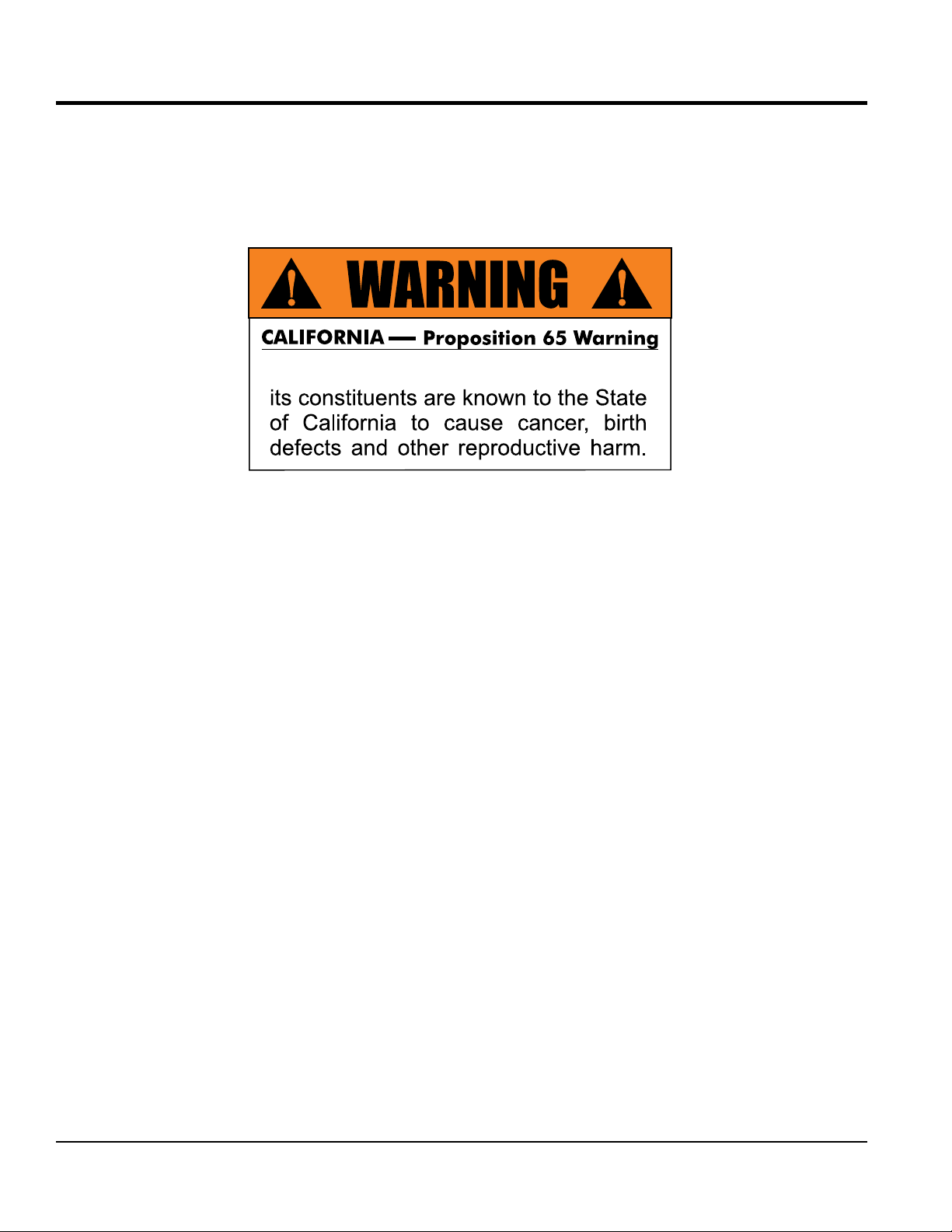
PROPOSITION 65 WARNING
Diesel engine exhaust and some of
PAGE 2 — AP6/AP8 SERIES TRASH PUMPS • OPERATION AND PARTS MANUAL — REV. #0 (06/11/14)
Page 3

REPORTING SAFETY DEFECTS
If you believe that your vehicle has a defect that could cause a crash or could
cause injury or death, you should immediately inform the National Highway
Traffi c Safety Administration (NHTSA) in addition to notifying Multiquip Inc. at
1-800-421-1244.
If NHTSA receives similar complaints, it may open an investigation, and if it
fi nds that a safety defect exists in a group of vehicles, it may order a recall and
remedy campaign. However, NHTSA cannot become involved in individual
problems between you, your dealer, or Multiquip Inc..
To contact NHTSA, you may either call the Vehicle Safety Hotline toll-free at
1-888-327-4236 (TTY: 1-800-424-9153), go to http://www.safecar.gov; or write
to:
Administrator
NHTSA
400 Seventh Street, SW.,
Washington, DC 20590
You can also obtain information about motor vehicle safety from
http://www.safecar.gov.
AP6/AP8 SERIES TRASH PUMPS • OPERATION AND PARTS MANUAL — REV. #0 (06/11/14) — PAGE 3
Page 4

TABLE OF CONTENTS
AP6/AP8 Trash Pump
Proposition 65 Warning ........................................... 2
Reporting Safety Defects ......................................... 3
Table Of Contents .................................................... 4
Parts Ordering Procedures ...................................... 5
Training Checklist .................................................... 6
Daily Pre-Operation Checklist ................................. 7
Safety Information .............................................. 8-13
Specifications (Pump) ............................................ 14
Specifications (Engine) .......................................... 15
Pump Dimensions (Canopy) .................................. 16
Pump Dimensions ................................................ 17
Performance Curves .............................................. 18
General Information ............................................... 19
Pump Components (AP6/AP8) ......................... 20-21
Engine Components (AP6) .............................. 22-23
Engine Control Box Components ......................... 24
Pumping Application .............................................. 25
Float Switches (Auto Mode) .................................. 26
Float Switches/Alarm Beacon (Auto Mode) ........... 27
Towing Application ................................................. 28
Inspection/Setup ............................................... 29-31
Operation (Manual Mode) ................................. 32-33
Operation (Auto Mode) ..................................... 34-38
Programming .................................................... 39-40
Programming Guide ......................................... 41-44
MSS-200 Diagnostics (Auto Mode) ....................... 45
MSS-200 Diagnostics (Manual mode) ................... 46
MSS-200 Troubleshooting ..................................... 47
Maintenance (Pump) ........................................ 48-51
Maintenance (Engine) ...................................... 52-58
Maintenance (Trailer) ........................................ 59-61
Trailer Safety Guidelines ................................... 62-75
Troubleshooting (Pump) ........................................ 76
Troubleshooting (Control Box) ............................... 77
Troubleshooting (Engine) ....................................... 78
Control Box Wiring Diagram (Manual Mode) ......... 79
Control Box Wiring Diagram (Auto Mode).............. 80
Engine Wiring Diagram ......................................... 81
Controller Application/Tach. Dip Switch Setting ..... 82
Tachometer VDO Adjustment Setting .................... 83
Explanation Of Code In Remarks Column............. 84
Suggested Spare Parts ......................................... 85
Component Drawings
Nameplate And Decals Assembly. .................... 86-91
Pump End Assembly. ........................................ 92-93
Air Separator Chamber Assembly. .................... 94-97
Check Valve Assembly. ..................................... 98-99
Control Box Assembly. .................................. 100-101
Battery Assembly. (AP6) ............................... 102-103
Battery Assembly. (AP8) ............................... 104-105
Pump/Engine Mounting Assembly. ............... 106-107
Control Box Mounting Assembly. .................. 108-109
Volute Water Valve Assembly. ....................... 110-111
Trailer Assembly. ........................................... 112-115
Canopy Assembly. ........................................ 116-117
John Deere 4024TF Engine Service Parts ... 118-119
John Deere 4045TF Engine Service Parts ... 120-121
Terms And Conditions Of Sale — Parts .............. 122
PAGE 4 — AP6/AP8 SERIES TRASH PUMPS • OPERATION AND PARTS MANUAL — REV. #0 (06/11/14)
Page 5
PARTS ORDERING PROCEDURES
www.multiquip.com
Ordering parts has never been easier!
If you have an MQ Account, to obtain a Username
parts@multiquip.
To obtain an MQ Account, contact your
Effective:
, 2006
Choose from three easy options:
January 1
st
Best Deal!
Order via Internet (Dealers Only):
Order parts on-line using Multiquip’s SmartEquip website!
View Parts Diagrams
Order Parts
Print Specifi cation Information
Goto www.multiquip.com and click on
Order Parts
to log in and save!
Order via Fax (Dealers Only):
All customers are welcome to order parts via Fax.
Domestic (US) Customers dial:
1-800-6-PARTS-7 (800-672-7877)
Order via Phone:
Non-Dealer Customers:
Contact your local Multiquip Dealer for
parts or call 800-427-1244 for help in
locating a dealer near you.
and Password, E-mail us at:
com.
District Sales Manager for more information.
Use the internet and qualify for a 5% Discount
on Standard orders for all orders which include
complete part numbers.*
Fax your order in and qualify for a 2% Discount
on Standard orders for all orders which include
complete part numbers.*
Domestic (US) Dealers Call:
1-800-427-1244
International Customers should contact
their local Multiquip Representatives for
Parts Ordering information.
Note: Discounts Are Subject To Change
Note: Discounts Are Subject To Change
AP6/AP8 SERIES TRASH PUMPS • OPERATION AND PARTS MANUAL — REV. #0 (06/11/14) — PAGE 5
When ordering parts, please supply:
Dealer Account Number
Dealer Name and Address
Shipping Address (if different than billing address)
Return Fax Number
Applicable Model Number
Quantity, Part Number and Description of Each Part
NOTICE
All orders are treated as Standard Orders and will
ship the same day if received prior to 3PM PST.
WE ACCEPT ALL MAJOR CREDIT CARDS!
Specify Preferred Method of Shipment:
UPS/Fed Ex DHL
Priority One Tr u ck
Ground
Next Day
Second/Third Day
Page 6

TRAINING CHECKLIST
TRAINING CHECKLIST
This checklist will lists some of the minimum requirements for machine maintenance and operation. Please feel free to
detach it and make copies. Use this checklist whenever a new operator is to be trained or it can be used as a review for
more experienced operator’s
Training Checklist
No, Description OK? Date
1
2
3 Fuel system, refueling procedure.
4
5
6 Emergency stop procedures.
7
8 Shutdown of machine.
9 Lifting of machine (lift loops).
10 Machine transport and storage.
Read operation manual
completely.
Machine layout, location of
components, checking of engine.
Operation of controls (machine
not running).
Safety controls, safety stop switch
operation.
Startup of machine, pre-heat,
engine choke.
PAGE 6 — AP6/AP8 SERIES TRASH PUMPS • OPERATION AND PARTS MANUAL — REV. #0 (06/11/14)
Page 7

DAILY PRE-OPERATION CHECKLIST
DAILY PRE-OPERATION CHECKLIST
Daily Pre-Operation Checklist
1 Hardware and damage check
2 Engine oil level
3 Braking control operation
AP6/AP8 SERIES TRASH PUMPS • OPERATION AND PARTS MANUAL — REV. #0 (06/11/14) — PAGE 7
Page 8
SAFETY INFORMATION
Do not operate or service the equipment before reading
the entire manual. Safety precautions should be followed
at all times when operating this equipment.
Failure to read and understand the safety
messages and operating instructions could
result in injury to yourself and others.
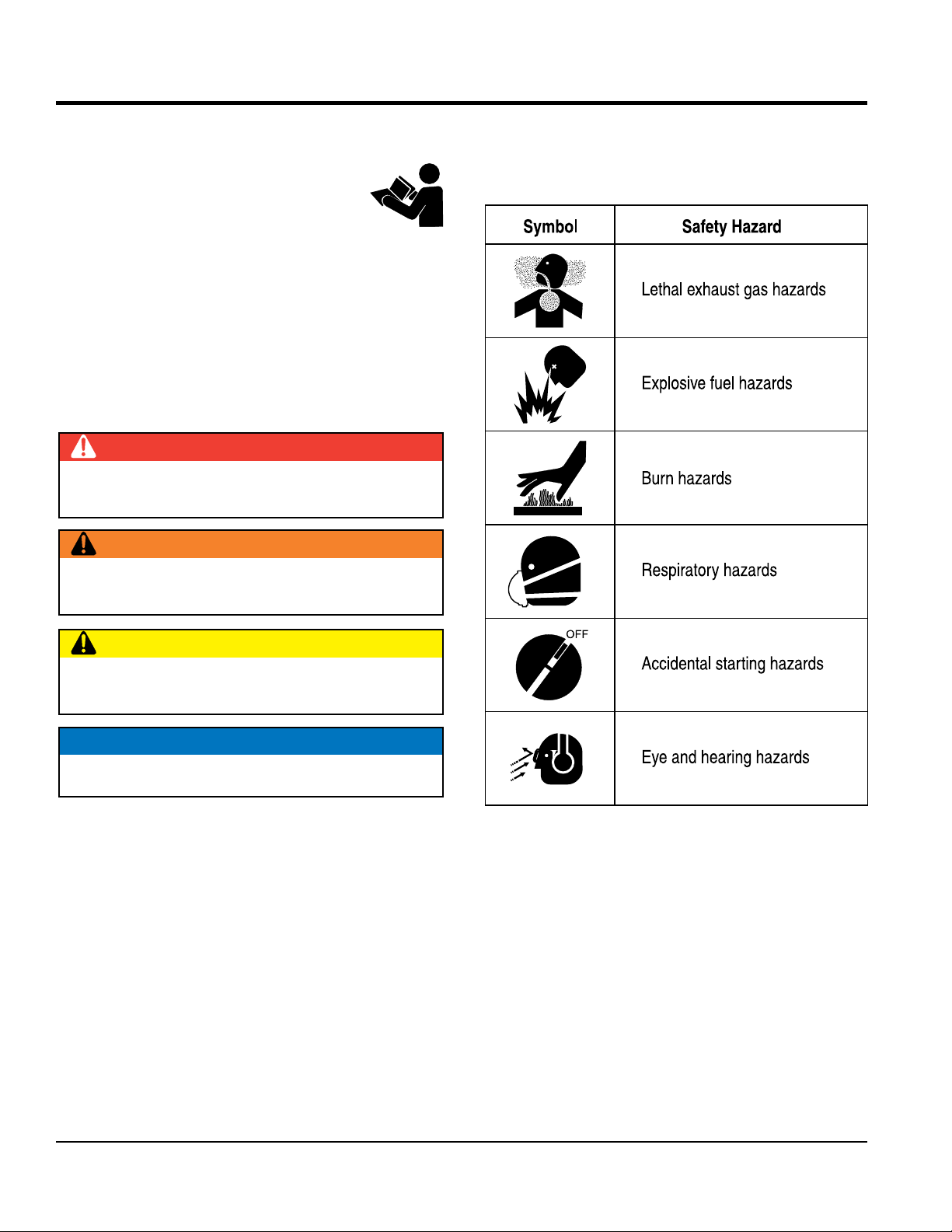
SAFETY MESSAGES
The four safety messages shown below will inform you
about potential hazards that could injure you or others. The
safety messages specifi cally address the level of exposure
to the operator and are preceded by one of four words:
DANGER, WARNING, CAUTION
SAFETY SYMBOLS
Potential hazards associated with the operation of this
equipment will be referenced with hazard symbols which
may appear throughout this manual in conjunction with
safety messages.
DANGER
Indicates a hazardous situation which, if not avoided,
WILL result in DEATH or SERIOUS INJURY.
WARNING
Indicates a hazardous situation which, if not avoided,
COULD result in DEATH or SERIOUS INJURY.
CAUTION
Indicates a hazardous situation which, if not avoided,
COULD result in MINOR or MODERATE INJURY.
or NOTICE.
NOTICE
Addresses practices not related to personal injury.
PAGE 8 — AP6/AP8 SERIES TRASH PUMPS • OPERATION AND PARTS MANUAL — REV. #0 (06/11/14)
Page 9
SAFETY INFORMATION
GENERAL SAFETY
PUMP SAFETY
pump volatile, explosive, fl ammable or low fl ash
The engine fuel exhaust gases contain poisonous carbon
monoxide. This gas is colorless and odorless, and can
The engine of this equipment requires an adequate free
operate this equipment in any
pump corrosive chemicals or water containing
toxic substances. These fl uids could create serious
health and environmental hazards. Contact local
operate the pump with closed discharge hose.
The liquid could reach boiling temperatures, build
emergency or safety devices.
These devices are intended for operator safety.
Disconnection of these devices can cause severe injury,
bodily harm or even death. Disconnection of any of these
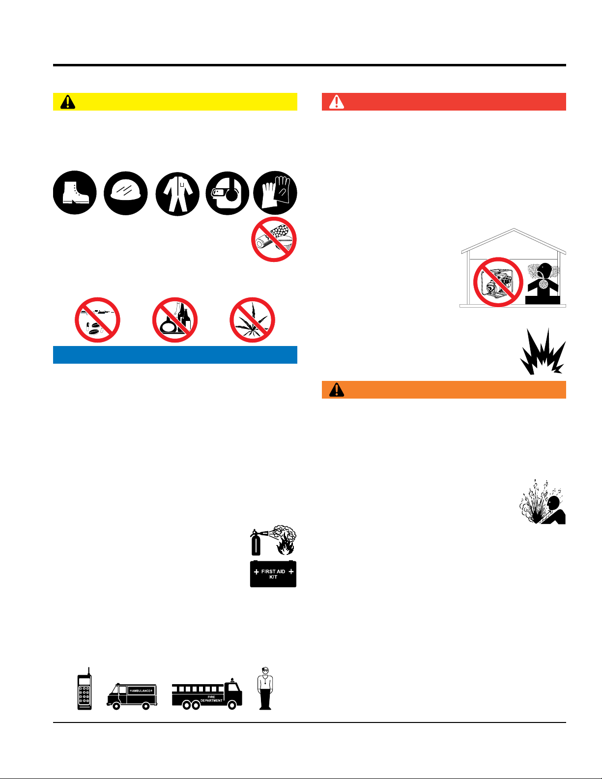
CAUTION
NEVER operate this equipment without proper protective
clothing, shatterproof glasses, respiratory protection,
hearing protection, steel-toed boots and other protective
devices required by the job or city and state regulations.
NEVER operate this equipment when not
feeling well due to fatigue, illness or when
under medication.
NEVER operate this equipment under the infl uence of
drugs or alcohol.
NOTICE
This equipment should only be operated by trained and
qualifi ed personnel 18 years of age and older.
DANGER
NEVER
point fl uids. These fl uids could ignite or explode.
cause death if inhaled.
fl ow of cooling air. NEVER
enclosed or narrow area
where free fl ow of the air is
restricted. If the air fl ow is
restricted it will cause injury
to people and property and
serious damage to the
equipment or engine.
NEVER operate the equipment in an explosive
atmosphere or near combustible materials. An
explosion or fi re could result causing severe
bodily harm or even death.
WARNING
DANGEROUS
GAS FUMES
Whenever necessary, replace nameplate, operation and
NEVER
safety decals when they become diffi cult read.
Manufacturer does not assume responsibility for any
accident due to equipment modifi cations. Unauthorized
equipment modifi cation will void all warranties.
NEVER use accessories or attachments that are not
recommended by Multiquip for this equipment. Damage
to the equipment and/or injury to user may result.
ALWAYS know the location of the nearest
fi re extinguisher.
authorities for assistance.
NEVER open the priming plug when pump
is hot. Hot water inside could be pressurized
much like the radiator of an automobile.
Allow pump to cool to the touch before
loosening plug. The possibility exists of
scalding, resulting in severe bodily harm.
NEVER
ALWAYS know the location of the nearest
fi rst aid kit.
ALWAYS know the location of the nearest phone or keep
a phone on the job site. Also, know the phone numbers
of the nearest ambulance, doctor and fi re department.
This information will be invaluable in the case of an
pressure, and cause the casing to rupture or explode.
NEVER run the pump dry.
NEVER disconnect any
emergency.
devices will void all warranties.l
AP6/AP8 SERIES TRASH PUMPS • OPERATION AND PARTS MANUAL — REV. #0 (06/11/14) — PAGE 9
Page 10
SAFETY INFORMATION
CAUTION
NEVER attempt suction lifts over 25 ft. (7.62 meters).
Keep suction lift to a minimum and support all hoses
lift the pump with suction or discharge hoses
place hands or fingers inside engine
operate the engine with heat shields or
run engine without an air fi lter or with a dirty air
fi lter. Severe engine damage may occur. Service air fi lter
NEVER lubricate components or attempt service on a
running machine.
NEVER block or restrict flow from discharge hose.
Remove kinks from discharge line before starting pump.
Operation with a blocked discharge line can cause water
inside pump to overheat.
NEVER allow the suction line to become clogged or
mired in mud. This condition could cause water inside
the pump to overheat creating a rupture or explosion.
NOTICE
ALWAYS fi ll the pump casing with water before starting
the engine. Failure to maintain water inside the pump
casing will cause severe damage to the pump and
mechanical seal.
FREEZING WEATHER
• In winter drain water from pump casing to prevent
freezing.
• If freezing of the pump is evident or suspected, stop
engine immediately.
NEVER start the pump with the clean-out cover removed.
The rotating impeller inside the pump can cut or sever
objects caught in it. Before starting the pump, check that
the clean-out cover is securely fastened.
and piping as needed.
NEVER pump sand, abrasive liquids, or solids.
NEVER
attached.
ENGINE SAFETY
WARNING
DO NOT
compartment when engine is running.
NEVER
guards removed.
DO NOT remove the engine oil drain plug
while the engine is hot. Hot oil will gush
out of the oil tank and severely scald any
persons in the general area of the pump.
CAUTION
NEVER touch the hot exhaust manifold,
muffl er or cylinder. Allow these parts to cool
before servicing equipment.
NOTICE
NEVER
ALWAYS keep the pump in proper running condition.
ALWAYS ensure pump is on level ground before use and
wheels are secured with chock blocks.
Fix damage to pump and replace any broken parts
immediately.
ALWAYS store equipment properly when it is not being
used. Equipment should be stored in a clean, dry location
out of the reach of children and unauthorized personnel.
ALWAYS make sure that all suction hose connections
are tighten securely.
NEVER operate the pump at an excessive angle of
inclination.
PAGE 10 — AP6/AP8 SERIES TRASH PUMPS • OPERATION AND PARTS MANUAL — REV. #0 (06/11/14)
frequently to prevent engine malfunction.
NEVER tamper with the factory settings
of the engine or engine governor. Damage
to the engine or equipment can result
if operating in speed ranges above the
maximum allowable.
Page 11
SAFETY INFORMATION
FUEL SAFETY
BATTERY SAFETY (ELECTRIC START ONLY)
keep the battery charged. If the battery is not
charge battery if frozen. Battery can explode.
When frozen, warm the battery to at least 61°F (16°C).
recharge the battery in a well-ventilated
environment to avoid the risk of a dangerous concentration
If the battery liquid (dilute sulfuric acid) comes into
, rinse eyes immediately with plenty
of water and contact the nearest doctor or hospital to
NEGATIVE battery terminal
keep battery cables in good working condition.
WARNING
DANGER
DO NOT start the engine near spilled fuel or combustible
fl uids. Fuel is extremely fl ammable and its vapors can
cause an explosion if ignited.
ALWAYS refuel in a well-ventilated area, away from
sparks and open fl ames.
ALWAYS use extreme caution when working with
fl ammable liquids.
DO NOT fi ll the fuel tank while the engine is running
or hot.
DO NOT overfi ll tank, since spilled fuel could ignite if it
comes into contact with hot engine parts or sparks from
the ignition system.
Store fuel in appropriate containers, in well-ventilated
areas and away from sparks and fl ames.
NEVER use fuel as a cleaning agent.
DO NOT smoke around or near the
equipment. Fire or explosion could result
from fuel vapors or if fuel is spilled on a
hot engine.
DANGER
DO NOT drop the battery. There is a possibility that the
battery will explode.
DO NOT expose the battery to open fl ames,
sparks, cigarettes, etc. The battery contains
combustible gases and liquids. If these
gases and liquids come into contact with a
fl ame or spark, an explosion could occur.
ALWAYS wear safety glasses when
handling the battery to avoid eye irritation.
The battery contains acids that can cause
injury to the eyes and skin.
Use well-insulated gloves when picking up
the battery.
ALWAYS
charged, combustible gas will build up.
DO NOT
ALWAYS
of combustible gases.
If the battery liquid (dilute sulfuric acid)
comes into contact with clothing or skin,
rinse skin or clothing immediately with
plenty of water.
contact with eyes
seek medical attention.
CAUTION
ALWAYS disconnect the
before performing service on the equipment.
ALWAYS
Repair or replace all worn cables.
AP6/AP8 SERIES TRASH PUMPS • OPERATION AND PARTS MANUAL — REV. #0 (06/11/14) — PAGE 11
Page 12
TRANSPORTING SAFETY
CAUTION
TOWING SAFETY
ALWAYS inspect the hitch and coupling for wear. NEVER
Check the tire air pressure on both towing vehicle and
Trailer tires should be infl ated to 50 psi cold.
safety
attach trailer’s safety chains to towing
make sure the vehicle and trailer directional,
backup, brake and trailer lights are connected and
unless
posted otherwise. Recommended off-road towing is not
Avoid sudden stops and starts. This can cause skidding,
or jack-knifi ng. Smooth, gradual starts and stops will
Trailer should be adjusted to a level position at all times
Raise and lock trailer wheel stand in up position when
rolling
underneath the trailer’s bumper
Use the trailer’s swivel jack to adjust the trailer height to
NEVER allow any person or animal to stand underneath
the equipment while lifting.
NOTICE
Before lifting, make sure that the equipment parts are not
damaged and screws are not loose or missing.
ALWAYS make sure forklift forks are inserted into pockets
(if applicable) as far as possible when lifting the pump.
ALWAYS shutdown engine before transporting.
NEVER lift the equipment while the engine is running.
Tighten fuel tank cap securely and close fuel cock to
prevent fuel from spilling.
Use one point suspension hook and lift straight upwards.
DO NOT lift machine to unnecessary heights.
ALWAYS tie down equipment during transport by
securing the equipment with rope.
SAFETY INFORMATION
tow a trailer with defective hitches, couplings, chains, etc.
trailer.
Also check the tire tread wear on both vehicles.
ALWAYS make sure the trailer is equipped with a
chain.
ALWAYS properly
vehicle.
ALWAYS
working properly.
DOT Requirements include the following:
• Connect and test electric brake operation.
• Secure portable power cables in cable tray with tie
wraps.
The maximum speed for highway towing is 55 MPH
to exceed 15 MPH or less depending on type of terrain.
Never allow any person or animal to stand underneath the
equipment while lifting.
CAUTION
Check with your local county or state safety
towing regulations, in addition to meeting
Department of Transportation (DOT)
Safety Towing Regulations, before towing
your generator.
Refer to MQ Power trailer manual for additional safety
information.
In order to reduce the possibility of an accident while
transporting the generator on public roads, ALWAYS
make sure the trailer that supports the generator and
the towing vehicle are mechanically sound and in good
operating condition.
ALWAYS shutdown engine before transporting
Make sure the hitch and coupling of the towing vehicle
are rated equal to, or greater than the trailer “gross
vehicle weight rating.”
improve towing.
Avoid sharp turns to prevent rolling.
when towing.
towing.
Place chock blocks underneath wheel to prevent
while parked.
Place support blocks
to prevent tipping while parked.
a level position while parked.
PAGE 12 — AP6/AP8 SERIES TRASH PUMPS • OPERATION AND PARTS MANUAL — REV. #0 (06/11/14)
Page 13

ENVIRONMENTAL SAFETY/DECOMMISSIONING
Decommissioning is a controlled process used to safely
retire a piece of equipment that is no longer serviceable.
If the equipment poses an unacceptable and unrepairable
safety risk due to wear or damage or is no longer cost
effective to maintain (beyond life-cycle reliability) and is to
be decommissioned (demolition and dismantlement),be
sure to follow rules below.
EMISSIONS INFORMATION
The diesel engine used in this equipment has been
designed to reduce harmful levels of carbon monoxide
(CO), hydrocarbons (HC) and nitrogen oxides (NOx)
This engine has been certifi ed to meet US EPA Evaporative
Attempting to modify or make adjustments to the engine
emission system by unauthorized personnel without proper
training could damage the equipment or create an unsafe
Additionally, modifying the fuel system may adversely affect
evaporative emissions, resulting in fi nes or other penalties.
The emission control label is an integral part of the emission
If a replacement emission label is needed, please contact
SAFETY INFORMATION
NOTICE
DO NOT pour waste or oil directly onto the ground, down
a drain or into any water source.
Contact your country's Department of
Public Works or recycling agency in your
area and arrange for proper disposal of
any electrical components, waste or oil
associated with this equipment.
When the life cycle of this equipment is over, remove
battery and bring to appropriate facility for lead
reclamation. Use safety precautions when handling
batteries that contain sulfuric acid.
When the life cycle of this equipment is over, it is
recommended that the pump and all other metal parts
be sent to a recycling center.
Metal recycling involves the collection of metal from
discarded products and its transformation into raw
materials to use in manufacturing a new product.
Recyclers and manufacturers alike promote the process
of recycling metal. Using a metal recycling center
promotes energy cost savings.
NOTICE
contained in diesel exhaust emissions.
emissions requirements in the installed confi guration.
condition.
Emission Control Label
system and is strictly controlled by regulations.
The label must remain with the engine for its entire life.
your authorized Engine Distributor.
AP6/AP8 SERIES TRASH PUMPS • OPERATION AND PARTS MANUAL — REV. #0 (06/11/14) — PAGE 13
Page 14

SPECIFICATIONS (PUMP)
Table 1. AP6 Series Pump Specifications
Model
Pump Mounting
Weight - lbs. (kg)
Max. Flow - gpm (lpm) 2,300 (8,706)
Max. Head - ft. (m) 110 (33.5)
Max. Head - PSI (kPa) 47.6 (322)
Suction Lift - ft. (meters) 28 (8.5)
Max. Solids - in. (mm) 3 (76.2)
Max. Water Temp. F° (C°) 212 (100)
Max. Casing - PSI (kPa) 195 (1,344)
Mechanical Seal Grease Lubricated
Fuel Consumption - gph (lph) 1.75 (6.62) @1,800 RPM
Operating Time 28 hrs.@ 1,800 RPM or 39 hrs.@ 1,600 RPM
Compressor Type Single Cylinder, Gear Drive @ 8.5 CFM
Sound Level dB(A) N/A 63 @ 23 ft. (7 meters)
AP6 AP6TB AP6TP AP6S AP6STB AP6STP AP6SAB AP6SAP
Skid
Mounted
2,915
(1,322)
Trailer,
Ball
Coupler
3,665
(1,662)
Trailer,
Pintle
Coupler
3,665
(1,662)
Skid
Mounted
4,300
(1,950)
Trailer, Ball
Coupler
4,300
(1,950)
Trailer,
Pintle
Coupler
4,950
(2,245)
Auto Start,
Trailer, Ball
Coupler
4,950
(2,245)
Auto Start,
Trailer,
Pintle
Coupler
4,980
(2,259)
Table 2. AP8 Series Pump Specifications
Model
Pump Mounting
Weight - lbs.(kg)
Max. Flow - gpm (lpm) 2,700 (9,464)
Max. Head - ft./m 213 (50.2)
Max. Head - PSI (kPa) 71.4 (492)
Suction Lift - ft. (meters) 28 (8.5)
Max. Solids - in. (mm) 4 (102)
Max. Water Temp. F° (C°) 212 (100)
Max. Casing - PSI (kPa) 195 (1,344)
Mechanical Seal Grease Lubricated
Fuel Consumption - gph (lph) 1.94 (7.34) @2,000 RPM
Operating Time 28 hrs.@ 2,000 RPM
Compressor Type Single Cylinder, Gear Drive @ 8.5 CFM
Sound Level dB(A) N/A 66 @ 23 ft. (7 meters)
AP8 AP8TB AP8TP AP8S AP8STB AP8STP AP8SAB AP8SAP
Skid
Mounted
3,425
(1,553)
Trailer,
Ball
Coupler
4,185
(1,898)
Trailer,
Pintle
Coupler
4,185
(1,898)
Skid
Mounted
5,037
(2,284)
Trailer, Ball
Coupler
5,825
(2,642)
Trailer,
Pintle
Coupler
5,825
(2,642)
Auto Start,
Trailer, Ball
Coupler
5,875
(2,664)
Auto Start,
Trailer, Pintle
Coupler
5,875
(2,664)
PAGE 14 — AP6/AP8 SERIES TRASH PUMPS • OPERATION AND PARTS MANUAL — REV. #0 (06/11/14)
Page 15

SPECIFICATIONS (ENGINE)
Table 3. Engine Specifications
Engine Manufacturer John Deere
Engine Model 4024TF281-49 4045TF290-66
Engine Type Turbo Diesel
EPA Tier Tier 4 Interim
Number of Cylinders 4
Bore/Stroke -
Displacement -
Power -
Oil Capacity -
in./mm 86 x 105 (3.39 x 4.13) 106 x 127 (4.17 x 5.00)
cu-in (liters) 2.44 (149) 4.5 (275)
hp/kW @ 2800 RPM 49 (36) 66 (49)
quarts (liters) 8.5 (8) 15.5 (14.7)
Oil Type John Deere Plus-50™ 10W-30, ACEA E4, E5 or E6
Cooling System Water Cooled
Fuel Type
Low Sulfur or Ultra Low Sulfur Diesel Fuel
No 2 Diesel Fuel
Starting Method Electric Start
Battery 175 Ah 900 CCA
Battery Dimensions -
Weight -
Dimensions -
lbs. (kg) 251 (553) 396 (873)
in./mm (LxWxH)
in./mm (LxWxH) 13 X 6.5 X 8.75/330 X 165 X 222
26.1 X 22.3 X 30.4
662 X 566 X 772
33.9 X 24.1 X 39.1
860 X 612 X 994
Table 4. Trailer Specifications
Model AP6 AP8
Axle, Single -
lbs. (kg) 5,000 (2,268)
Stablizer Jacks (Front/Rear) 4
Top Wind Swivel Jack (Tongue) 1
Brakes Electric/ With Breakaway Switch
Coupler 2-5/16" Ball/3-inch Pintle
Tires (2) ST225/75D15
Lights DOT Approved
Safety Chain, Hook Type
Fuel Tank Capacity -
gallons (liters) 50 (189) 55 (208)
Dimensions Reference Table 6, Figure 2
AP6/AP8 SERIES TRASH PUMPS • OPERATION AND PARTS MANUAL — REV. #0 (06/11/14) — PAGE 15
Page 16
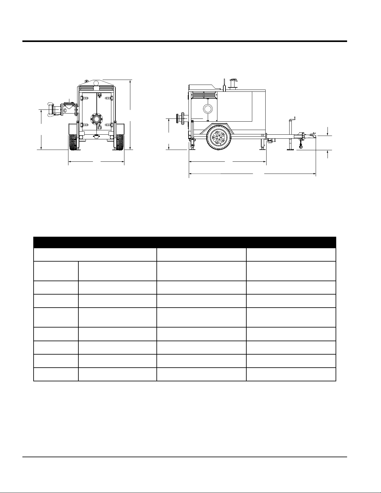
PUMP DIMENSIONS (CANOPY)
A
F
E
B D
C
Figure 1. Pump Dimensions (Canopy)
G
Table 5. Pump Dimensions (Canopy)
MODEL AP6 AP8
REFERENCE
LETTER
DESCRIPTION DIMENSIONS: IN. (MM) DIMENSIONS: IN. (MM)
A HEIGHT 83 (2,108) 90 (2,286)
B WIDTH 65 (1,651) 65 (1,651)
C
(TONGUE EXTENDED)
LENGTH
118 (2,997) 118 (2,997)
D SHIPPING LENGTH 71 (1,803) 71 (1,803)
E SUCTION HEIGHT 38 (965) 39 (991)
F DISCHARGE HEIGHT 48 (1,219) 48 (1,219)
G COUPLER HEIGHT 18 (457) 18 (457)
PAGE 16 — AP6/AP8 SERIES TRASH PUMPS • OPERATION AND PARTS MANUAL — REV. #0 (06/11/14)
Page 17
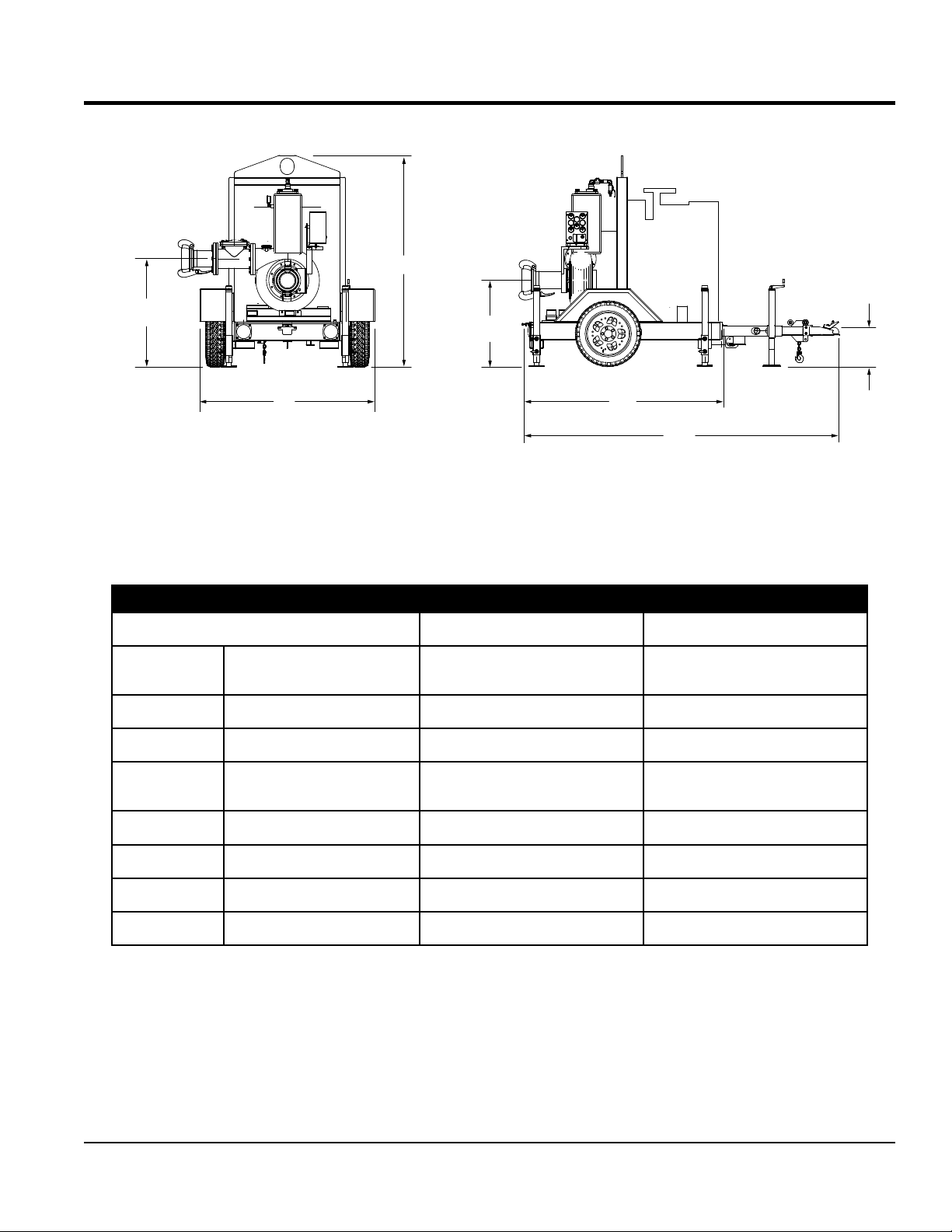
A
C
PUMP DIMENSIONS
F
E
B
Figure 2. Pump Dimensions (Without Canopy)
Table 6. Pump Dimensions (Without Canopy)
MODEL AP6 AP8
REFERENCE
LETTER
A HEIGHT 83 (2,108) 90 (2,286)
B WIDTH 65 (1,651) 65 (1,651)
DESCRIPTION DIMENSIONS: IN. (MM) DIMENSIONS: IN. (MM)
D
G
C
D SHIPPING LENGTH 71 (1,803) 71 (1,803)
E SUCTION HEIGHT 38 (965) 39 (991)
F DISCHARGE HEIGHT 48 (1,219) 48 (1,219)
G COUPLER HEIGHT 18 (457) 18 (457)
AP6/AP8 SERIES TRASH PUMPS • OPERATION AND PARTS MANUAL — REV. #0 (06/11/14) — PAGE 17
(TONGUE EXTENDED)
LENGTH
118 (2,997) 118 (2,997)
Page 18
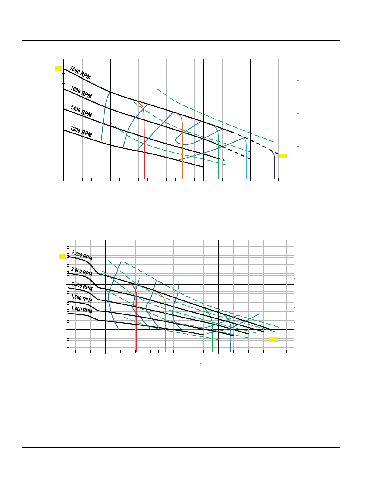
PERFORMANCE CURVES
Total Dynamic Head -
Meters
GPM
m3/hr
250
GPM
120
110
100
60%
80
75%
60
40
Total Dynamic Head - FEET
80%
80%
75%
20HP
20
10HP
0
25 FT
20 FT 15 FT
10 FT
0 500 1, 000 1,500 2,000 2,500
0 100 200 300 400 500
Figure 3. AP6 Series Pump Curve
30HP
2,300
5 FT
35
30
25
20
15
10
5
0
70
213
200
60%
70%
75%
80%
60
50
150
40
100
50
Total Dynamic Head - Feet
20HP
0
25
FT
0 500 1,000 1,500 2,000 2,500 3,000
0 100 200 300 400 500 600
20
FT
15
FT
80% 75%
40HP
30HP
10
FT
50HP
2,700
60HP
30
20
Total Dynamic Head - Meters
10
0
m3/hr
Figure 4. AP8 Series Pump Curve
PAGE 18 — AP6/AP8 SERIES TRASH PUMPS • OPERATION AND PARTS MANUAL — REV. #0 (06/11/14)
Page 19

GENERAL INFORMATION
The Multiquip AP6/AP8 series pumps are automatic primeassist pumps that can handle dewatering, sewer bypass,
and wellpoint applications.
The AP6/AP8 series pumps use a vacuum pump to remove
the air. This becomes important in certain applications such
as long suction hose runs or multiple suction points (such
as wellpoints). In these cases, high volumes of air enters
into the pump.
The AP6/AP8 series pumps use direct-drive vacuum pump
to efficiently remove very large volumes of air quickly to
obtain the priming necessary for these special applications.
The AP6/AP8 series pumps are very useful when you have
to move a lot of water fast.
IMPELLER
The impeller used on the AP6/AP8 series pumps has a
patented design to eliminate cavitation. It is a closed 2-blade
spiral, smooth flow, open, non-clog impeller, designed to
handle up to 3 or 4 inch solids depending on pump model.
The impeller pulls water directly into the pump from the
priming tank, reducing friction losses, and then pushes
it out the volute discharge. This design does not cause
turbulence normally found in centrifugal pumps.
WEAR PLATE
In conjunction with the impeller, the wear plate gives a
perfect match for great pump performance and durability.
The wear plate can be fully adjusted up to .6 inch (15 mm)
for wear.
PRIMING SYSTEM
The vacuum system is innovative, simple, yet rugged and
dependable. It uses direct drive which means no belt failure
and with only one moving part, means no maintenance.
It uses liquid-ring design with a closed water system.
Separate oil bath lubrication, for the seal and bearings with
oil reservoir, can run dry without damage. It operates quietly
with no pollution or unwanted discharge noise.
FLOAT AND BACKFLUSH (PRIMING TANK)
The priming tank float is a one-piece welded construction,
rubber valve seat, self-aligning rubber hinge. This design
increases reliability. The backflush valve allows for cleaning
of the suction strainer or wellpoint heads while the engine
is running.
FUEL SYSTEM
The AP6 and AP8 series pumps have fuel tanks integrated
into the trailer. These fuel tanks provide each pump with the
capability for continuous running for long-term jobs. There
are two corner fuel drains to check the condition of the fuel.
AP6 Series Fuel Tank
Fuel tank capacity for the AP6 series pumps is 50 gallons
(189 liters) with a run time of 28 hours @1800 rpm or 39
hours @1600 rpm.
AP8 Series Fuel Tank
Fuel tank capacity for the AP8 series pumps is 55 gallons
(208 liters) with a run time of 28 hours @2000 rpm.
FRAME AND TRACKBAR SYSTEM
The TrackBar system allows for the easy addition of jack
stands, fenders, axle, lifting bail, and other options.
This allows for fast and easy positioning of the jack stands
on the job site to fit the application, or to add subtract jack
stands as required. The removable, retractable towing
tongue minimizes storage requirements.
VOLUTE
The pump volute has an external inspection/clean-out cover
to inspect or clear the impeller. The pump shaft bearings
and mechanical seal are run in independent oil baths for
low maintenance.
LOFA ENGINE CONTROL PANEL
This control panel provides five engine status gauges (oil
pressure, tachometer, high coolant temperature, hour meter
and volt meter) along with engine shutdown capability in
the event of low oil pressure, high coolant temperature, and
alternator belt breakage.
An optional auto-start module is also available with float
switch capability which is designed for the automatic startstop of the pump. Additionally, audible and visual alerts
signal engine restarting through a control panel alarm and
beacon attachment.
AP6/AP8 SERIES TRASH PUMPS • OPERATION AND PARTS MANUAL — REV. #0 (06/11/14) — PAGE 19
Page 20
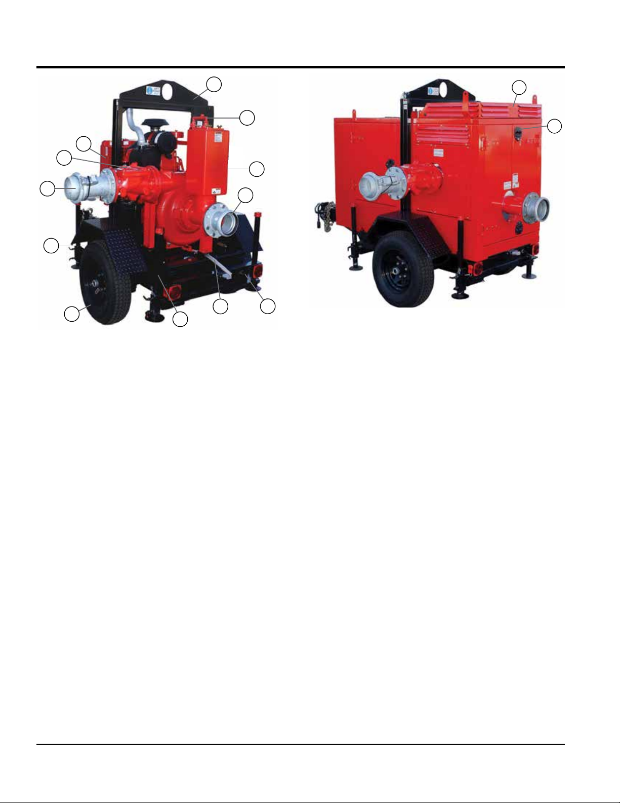
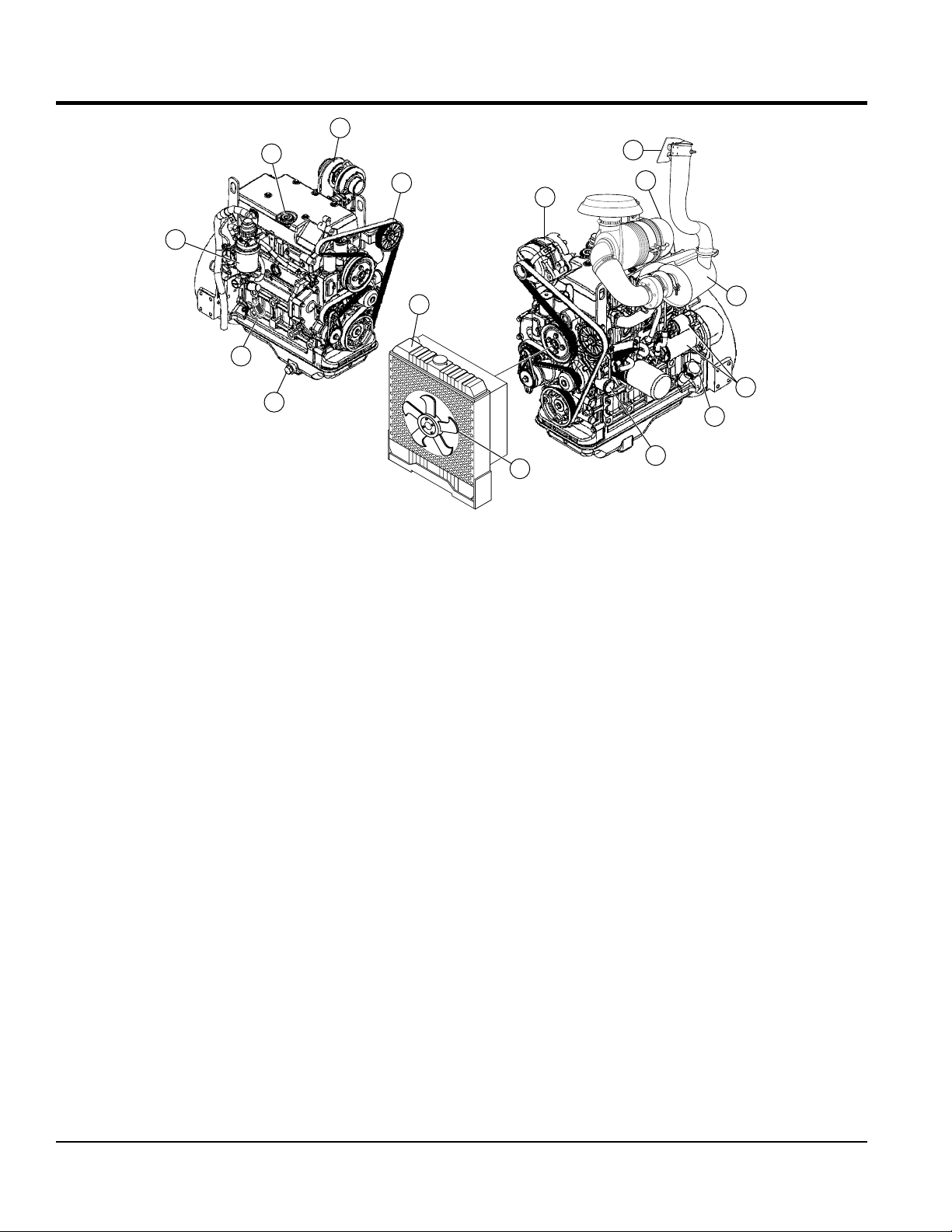
PUMP COMPONENTS (AP6/AP8)
4
5
3
2
6
1
12
11
10
7
9
Figure 5. Pump Components
8
Figure 5 and Figure 6 show the location of the components
for the AP6/AP8 series pumps. The function of each
component or control is described below:
1. Discharge Port – When connecting discharge hose
to this port, use galvanized Bauer flange ball coupler.
2. ValveMatic Discharge Valve – For low friction, high
flow water discharge. 100% airtight, Ductile Iron w/
epoxy coating, no slam flapper valve design with easy
access clean-out.
3. Diesel Engine – AP6 series pumps use a John Deere
49 HP turbo diesel engine and the AP8 series pumps
use a 66 HP John Deere turbo diesel engine. Reference
Table 3 for more detailed information.
4. Lifting Bail – Attach a suitable lifting device to this
lifting point when lifting of the pump is required. Lifting
device should be capable of lifting 6,000 lbs. (2,721 kg)
maximum.
5. Flooded Suction Valve – Easy ON/OFF ball valve that
quickly orients the pump to provide flooded suction
operation.
6. Air Separator Chamber – Component essential in
suction air evacuation that assists in the automatic
pump priming process. Easy clean out port and quick
action flooded suction valve.
13
14
AP6/AP8 Silent Canopy Series
7. Suction Port – When connecting suction hose to this
port use galvanized Bauer flange socket coupler.
8. Fuel Drain Plug – Remove this plug to drain the fuel.
9. Air Discharge Hose/Drain – Air outlet for the venturi
priming system. Can also be used to drain water from
the pump.
10. Leveling Jackstand (4) – Use these four adjustable
jack stands (front/rear) to level and stabilize the pump.
Always make sure jack stands are deployed before
operating pump and make sure pump is always placed
on secure level ground where it will not slip or slide.
11. Tires – Both AP6/AP8 series pumps use ST225/75D15
type tires. Replace with only recommended type tires.
Replace defective or worn tires immediately.
12. Tie Down Rings (4) – Solid tie down eyelets for safe
flat bed and vehicle transportation.
13. Silent Canopy – To reduce noise, a sound attenuated
canopy is available. The AP6 will maintain a sound level
of 63 dB(A), while the AP8 canopy series will provide
a sound level of 66 dB(A) @ 23 ft. (7 meters)
14. Locking Handle – The silent canopy provides for six
locking-hinged doors with three removal panels that
allow unrestricted access to all compartments for
servicing.
PAGE 20 — AP6/AP8 SERIES TRASH PUMPS • OPERATION AND PARTS MANUAL — REV. #0 (06/11/14)
Page 21
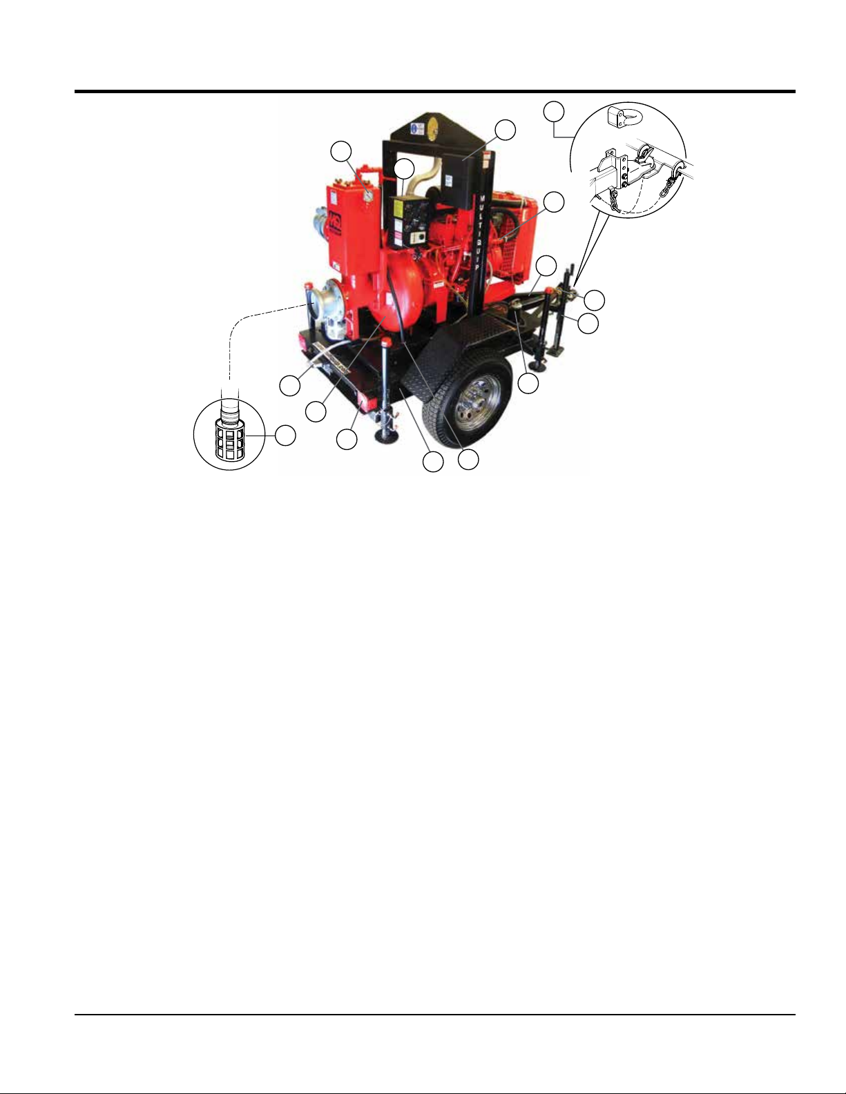
15
PUMP COMPONENTS (AP6/AP8)
18
17
16
Figure 6. Pump Components
28
27
29
26
15. Air Separator Vacuum Gauge – 0 to 30 in. Hg
(0~762 mm Hg) vacuum gauge that indicates vacuum
pressure. Under normal operating conditions this gauge
should read between 24~25 in. Hg (610~635 mm Hg).
16. Control Box – Displays vital engine parameters via
gauges and LEDs. Included gauges are tachometer,
temperature, battery voltage, hour meter, oil pressure.
Engine fault LEDs include battery discharge, low oil
pressure, high temperature, alternator failure and
V-belt failure.
17. Document Box – Contains all documentation relating
to the pump or engine.
18. Couplers – Trailer is available with either a 2-5/16 inch
ball coupler or a 3-inch pintel coupler.
19. Compressor – Single cylinder, water cooled, gear
driven 8.5 CFM compressor that is an integral
component of the automatic priming system.
20. DOT Approved Trailer – Industrial DOT/NHTSA
certified trailer. Includes break-away electric brakes,
lashing rings, stabilizer stands and includes fuel cell.
21. Safety Chains – Heavy duty safety tow chains with
locking coupler. Always cross chains when connecting
to the ow vehicle.
22. Top-Wind Jack – Levels trailer tongue when
connecting to a tow vehicle.
19
20
21
22
23
24
25
23. Fuel Cap/Fuel Filler Port – Lockable, EPA approved
fuel cap with filtration screen and security chain. Use
only No. 2 diesel fuel when replenishing fuel.
24. Venturi Assembly – Facilitates the creation of
24~25 inches (610~635 mm) of vacuum and works
in conjunction with the air separator chamber for the
automatic priming process.
25. Fuel Tanks – The AP6 pump is available with a 50
gallon (190 liters) fuel tank, while the AP8 is equipped
with a 55 gallon fuel tank (208 liters). Both fuel tanks
are constructed of heavy gauge steel.
26. Tailights – ALWAYS make sure lights are working
correctly before towing.
27. Pump End – Pump casing is 3/4-inch thick class 30
cast iron with built in volute. Pressure rated up to 195
PSI. Casing includes ductile iron high efficiency closed
impeller and 416 stainless steel shaft sleeve.
28. License Plate Light – ALWAYS make sure light is
working correctly before towing at night.
29. Strainer – Always attach a strainer to bottom side of
the suction hose to prevent large objects and debris
from entering the pump. Strainer should be positioned
so that it will remain completely under water. Running
the pump with the strainer above water for long periods
can damage pump.
AP6/AP8 SERIES TRASH PUMPS • OPERATION AND PARTS MANUAL — REV. #0 (06/11/14) — PAGE 21
Page 22
ENGINE COMPONENTS (AP6)
5
4
10
6
3
7
2
1
Figure 7. JD 4024TF Basic Engine Components
Figure 7 illustrates the location of the basic components
for the John Deere Model 4024TF air cooled diesel engine.
See Table 2 for engine specifications. The function of each
component is described below:
1. Crankcase Drain Plug – Remove this plug to
drain engine oil from the crankcase. Replace
with recommended engine oil as specified in the
maintenance section of this manual.
2. In-Line Fuel Filter – Replace or clean fuel filter as
specified in the maintenance section of this manual.
3. Primary Fuel Filter – Replace or clean the fuel filter
as specified in the maintenance section of this manual.
4. Oil Filler Port Cap – Remove this cap to add engine
oil to the crankcase. Fill with recommended type oil as
specified in the maintenance section of this manual.
5. Turbocharger – Pushes the fuel and air mixture into
the engine at a high pressure to increase power.
6. Drive Belt – ALWAYS make sure that drive belt is
properly tensioned. A loose or defective drive belt can
adversely affect the performance of the pump.
7. Radiator – Only fill with recommended coolant.
Reference maintenance section in this manual for
correct type of coolant.
9
8
11
12
13
14
15
8. Alternator – Provides power to the electrical system.
Replace with only manufactures recommended type
alternator.
9. Air Cleaner – Prevents dirt and other debris
from entering the fuel system. Replace with only
manufactures recommended type air cleaner.
10. Muffler Rain Cap – Always make sure rain cap is
in place (closed) when engine is not in use. This will
prevent water and dirt from entering the engine.
11. Muffler/Guard – DO NOT touch the muffler when
engine is running. The muffler can become extremely
hot, causing severe burns. NEVER run the pump with
the muffler guard removed.
12. Starter Motor/Solenoid – NEVER allow water or
any foreign debris to come in contact with the starter
motor/solenoid.
13. Oil Filler Port/Dipstick – Remove this dipstick to
determine if engine oil is low. Maintain oil level at the
"H "marking on the dipstick. NEVER run engine with
low oil.
14. Oil Filter – Replace oil filter as recommended in the
maintenance section of this manual.
15. Cooling Fan Blades – Make sure that the blades of
the cooling fan are not bent or broken. A damaged fan
blade can cause the engine to run hot and overheat.
PAGE 22 — AP6/AP8 SERIES TRASH PUMPS • OPERATION AND PARTS MANUAL — REV. #0 (06/11/14)
Page 23
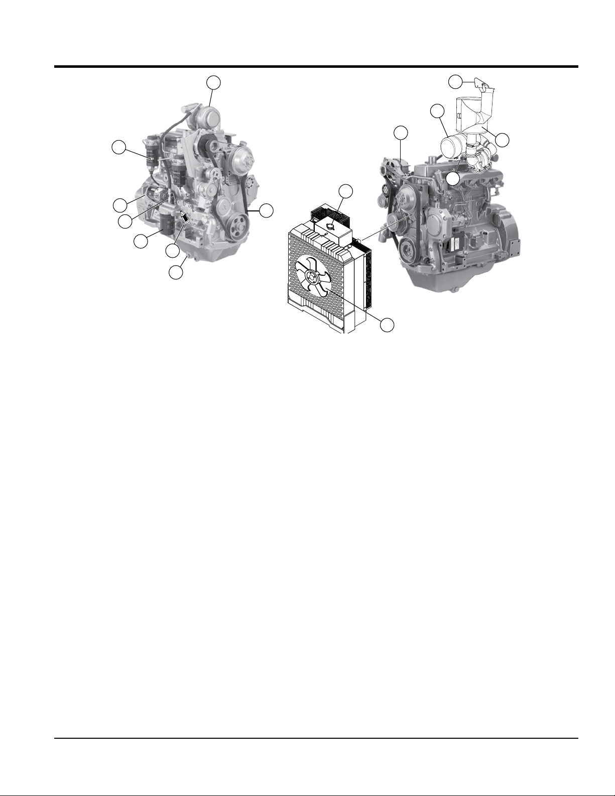
ENGINE COMPONENTS (AP8)
7
6
5
4
3
2
1
Figure 8. JD 4045TF Basic Engine Components
8
Figure 8 illustrates the location of the basic components
for the John Deere Model 4045TF air cooled diesel engine.
See Table 2 for engine specifications. The function of each
component is described below:
1. Crankcase Drain Plug – Remove this plug to
drain engine oil from the crankcase. Replace
with recommended engine oil as specified in the
maintenance section of this manual.
2. In-Line Fuel Filter – Replace or clean fuel filter as
specified in the maintenance section of this manual.
3. Oil Filter – Replace oil filter as recommended in the
maintenance section of this manual.
12
11
10
14
9
15
13
9. Radiator – Only fill with recommended coolant.
Reference maintenance section in this manual for
correct type of coolant.
10. Alternator – Provides power to the electrical system.
Replace with only manufactures recommended type
alternator.
11. Air Cleaner – Prevents dirt and other debris
from entering the fuel system. Replace with only
manufactures recommended type air cleaner.
12. Muffler Rain Cap – Always make sure rain cap is in
place when engine is not in use. This will prevent water
and dirt from entering the engine.
4. Dipstick – Remove this dipstick to determine if engine
oil is low. Maintain oil level at the "H "marking on the
dipstick. NEVER run engine with low oil.
5. Starter Motor/Solenoid – NEVER allow water or
any foreign debris to come in contact with the starter
motor/solenoid.
6. Primary Fuel Filter – Replace or clean the fuel filter
as specified in the maintenance section of this manual.
7. Turbocharger – Pushes the fuel and air mixture into
the engine at a high pressure to increase power.
13. Muffler/Guard – DO NOT touch the muffler when
engine is running. The muffler can become extremely
hot, causing severe burns. NEVER run the pump with
the muffler guard removed.
14. Oil Filler Port Cap – Remove this cap to add engine
oil to the crankcase. Fill with recommended type oil as
specified in the maintenance section of this manual.
15. Cooling Fan Blades – Make sure that the blades of
the cooling fan are not bent or broken. A damaged fan
blade can cause the engine to run hot and overheat.
8. Drive Belt – ALWAYS make sure that drive belt is
properly tensioned. A loose or defective drive belt can
adversely affect the performance of the pump.
AP6/AP8 SERIES TRASH PUMPS • OPERATION AND PARTS MANUAL — REV. #0 (06/11/14) — PAGE 23
Page 24
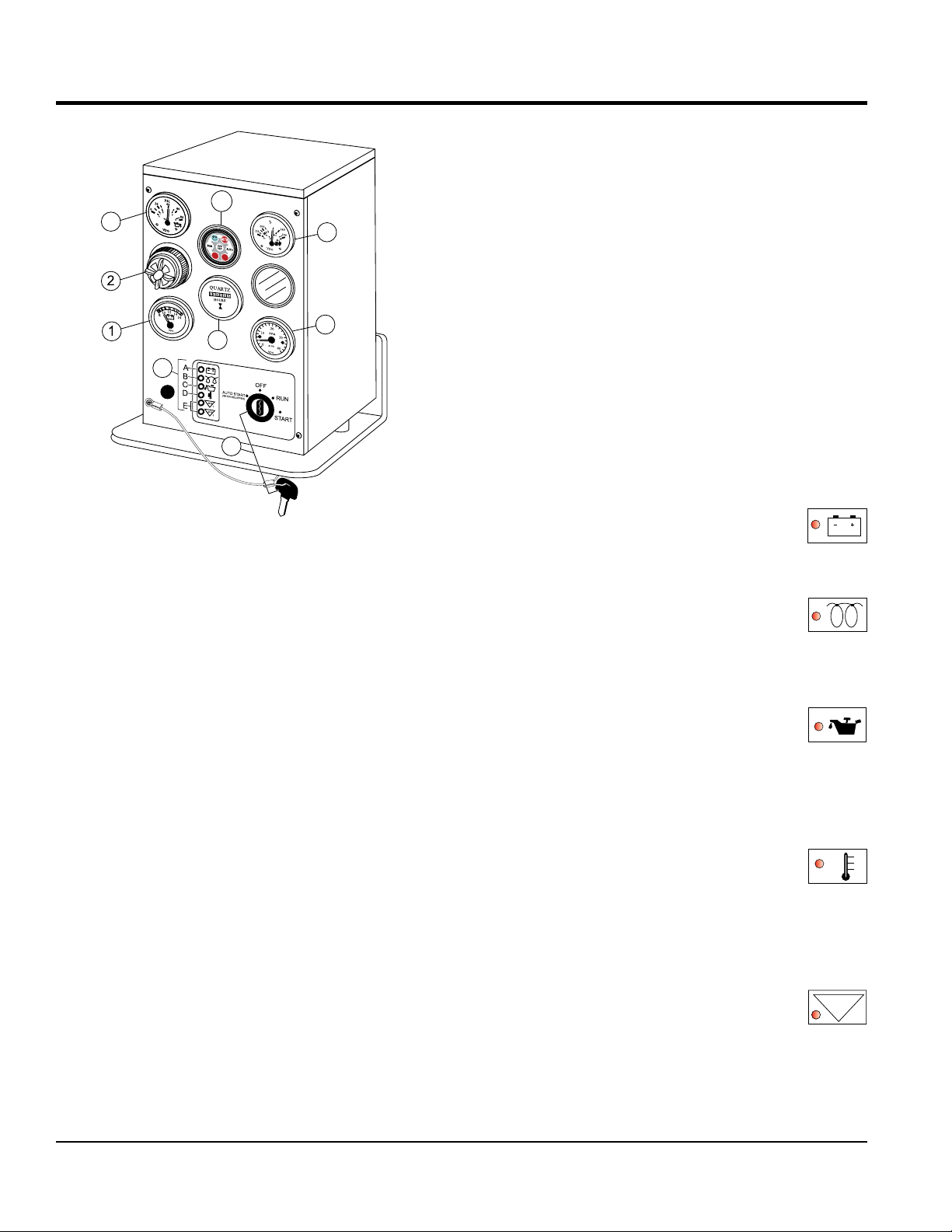
ENGINE CONTROL BOX COMPONENTS
8
9
3
4
5
6
7
Figure 9. EP250 Control Box
Figure 9 shows the location of the components for the
engine control box. The function of each component is
described below:
1. Voltmeter Gauge – Indicates battery voltage. If battery
voltage reading is approximately 14 volts while the
engine is running indicates the battery is charging
properly.
2. Audible Alarm - When remote starting (auto mode)of
the pump is required this alarm will sound indicating
that the engine will begin cranking.
3. Oil Pressure Gauge - Indicates the oil pressure of
the engine. Under normal operating conditions the oil
pressure is approximately 50~52 psi. (345~358 kPa).
4. MS-200 Programmable Auto Start Controller - The
MSS-200 controller is an optional add-on component
for the MSS-200 automatic start stop module (float
switches).
5. Coolant Temperature Gauge - Indicate the coolant
temperature. Under normal operating conditions the
coolant temperature should be between 170°~200°F
(77°~93°C).
6. Engine Tachometer – Indicates the speed of the
engine when the pump is operating. Under normal
operating conditions this speed is approximately 2200
RPM’s.
7. Engine Hour Meter – Indicates the number of hours
the engine has been in use.
8. Ignition Switch/Key – To start engine, insert ignition
key into ignition and turn clockwise to the RUN position,
then continue turning clockwise to the START position
and release. To stop the engine turn ignition key fully
counterclockwise to the OFF position.
9. Engine Warning Status LEDs — These engine status
indicators when active (ON) indicate battery discharge,
low oil pressure, high coolant temperature, alternator
failure and V-belt failure. LEDs will remain ON indicating
fault until reset:
a. Battery Charge LED — When ON
indicates that the charging system is
not working properly. This condition will
cause the engine to shutdown..
b. Glow Plug Pre-Heat LED — This LED
goes ON when the preheat system is in
process. When LED extinguishes, the
preheat period is complete and the
engine may be cranked..
c. Low Oil Pressure LED — When ON
indicates that the oil pressure has
dropped to 11.4 psi (78.6 kPa). This
condition will cause the engine to
shutdown. During normal operation of
the pump this LED should remain OFF.t
d. Overheat LED — This LED goes ON
when the cooling water temperature
rises above 225°F, ± 5°F (107°C, ± 5°C).
If this LED comes ON during normal
operation of the pump, the emergency
shutdown device will stop the engine
automatically.
e. Auxiliary LEDs — These status LEDs
can be used for additional engine
operating parameters. Currently these
AUX
1~2
two status LEDs are not used.
PAGE 24 — AP6/AP8 SERIES TRASH PUMPS • OPERATION AND PARTS MANUAL — REV. #0 (06/11/14)
Page 25
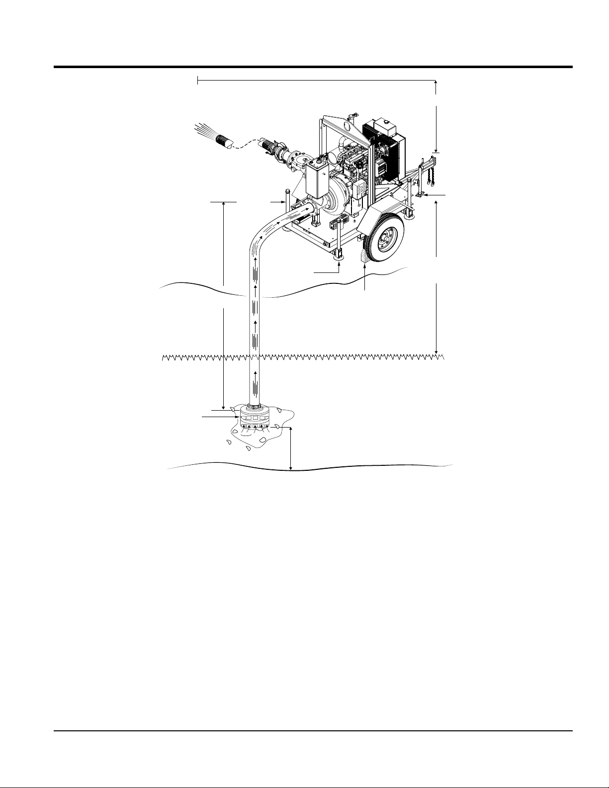
DISCHARGE HOSE
PUMPING APPLICATION
DISCHARGE HEAD
STRAINER
SUCTION HOSE
JACK
STAND
JACK
STAND
DO NOT LAY
STRAINER ON
BOTTOM SURFACE
CHOCKED
BLOCKS
(PREVENT ROLLING)
BOTTOM
SURFACE
STATIC
SUCTION
LIFT
JACK
STAND
Figure 10. Pump Application
Figure 10 shows a typical application using the Dry Prime
diesel-powered prime-assist pump. Please note that this
pump is intended for the removal of clean water and water
containing some debris and solids. Maximum size of solids
should not exceed 3.2 inches (81.2 mm) in diameter. DO
NOT set strainer on bottom of water bed.
Placing the strainer above the water bed will prevent the
pump from drawing in excessive amounts of sand and
foreign debris.
The following terms are usually used when referring to lift
or head:
1. Static Suction Lift – The vertical distance from the water
2. Static Discharge Head – The vertical distance from
the discharge outlet to the point of discharge or liquid
level when discharging into the bottom of a water tank.
3. Dynamic Suction Head – The static suction lift plus
the friction in the suction line. Also referred to as total
suction head.
4. Dynamic Discharge Head – The static discharge head
plus the friction in the discharge line. Also referred to
as total discharge head.
5. Total Dynamic Head – The Dynamic Head Suction
Head plus the Dynamic Discharge Head. Also referred
to as total head.
line to the center of the impeller.
AP6/AP8 SERIES TRASH PUMPS • OPERATION AND PARTS MANUAL — REV. #0 (06/11/14) — PAGE 25
Page 26
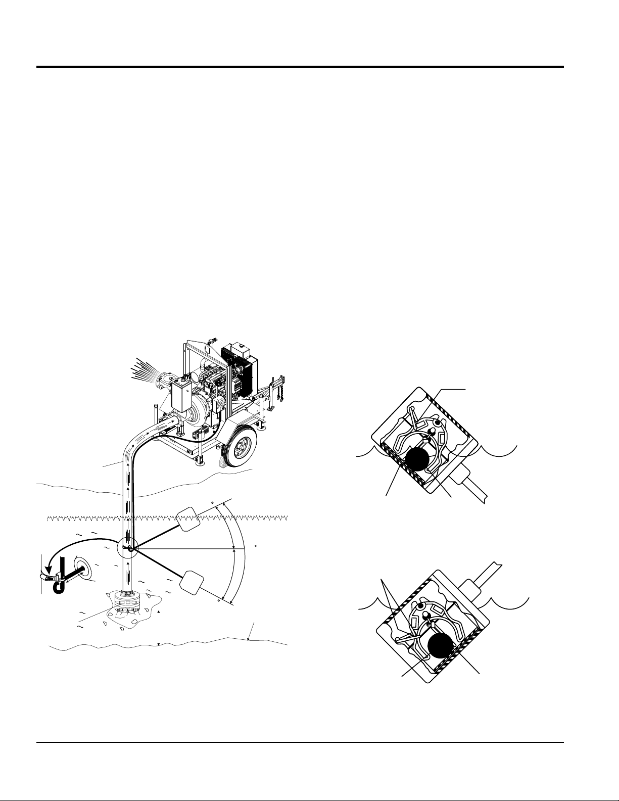
FLOAT SWITCHES (AUTO MODE)
CONTACTS
Mechanical Float Switch
For unattended operation of the pump two mechanically
activated float switches will be required. These float
switches can be connected directly to EP250 control box
via a 4-pin connector located at the rear of the control box.
When the pump is placed in AUTO mode, the float switches
will allow the pump to start and stop depending on the
length of the tether.
How It Works
The mechanical float switch control will turn ON (closes)
when the float tips 45° above horizontal, indicating a high
level. It turns OFF (opens) when the float switch drops
45° below horizontal. Reference Figure 12 and Figure 13.
Maximum pumping range is 120 degrees. See Figure 11
below.
Pumping Range
The pumping range of the pump is determined by the float
switch tether cord. Use Table 7 as guide line to determine
your required pumping range. Pumping ranges are based
on non-turbulent conditions. Range may vary due to water
temperature and cord shape. Please note as the tether
length increases, so does the variance of the pumping
range.
Design Features
Float switch housings are constructed of high-impact,
corrosion resistant polypropylene with mechanically
activated, snap action contacts.
Suitable for most liquid environments.
Hermetically sealed.
Thick-walled non-corrosive PVC plastic enclosure.
Pressure tested to 30 ft. (9 meters).
Standard SJO, 16-gauge, 2 conductor cord (20 ft./6.09 m).
SUCTION HOSE
PUMP
ON
60
120
3.5 in. (9 cm.)
MINIMUM
TETHER
LENGTH
STRAINER
Figure 11. Pumping Range (Float Switch)
PUMP
OFF
DO NOT LAY
STRAINER ON
BOTTOM SURFACE
60
BOTTOM
SURFACE
CLOSED
ON/OFF
RAMP
STEEL
BALL
Figure 12. Float Switch (Closed)
CONTACTS
OPEN
STEEL
BALL
ON/OFF
RAMP
Figure 13. Float Switch (Open)
PAGE 26 — AP6/AP8 SERIES TRASH PUMPS • OPERATION AND PARTS MANUAL — REV. #0 (06/11/14)
Page 27
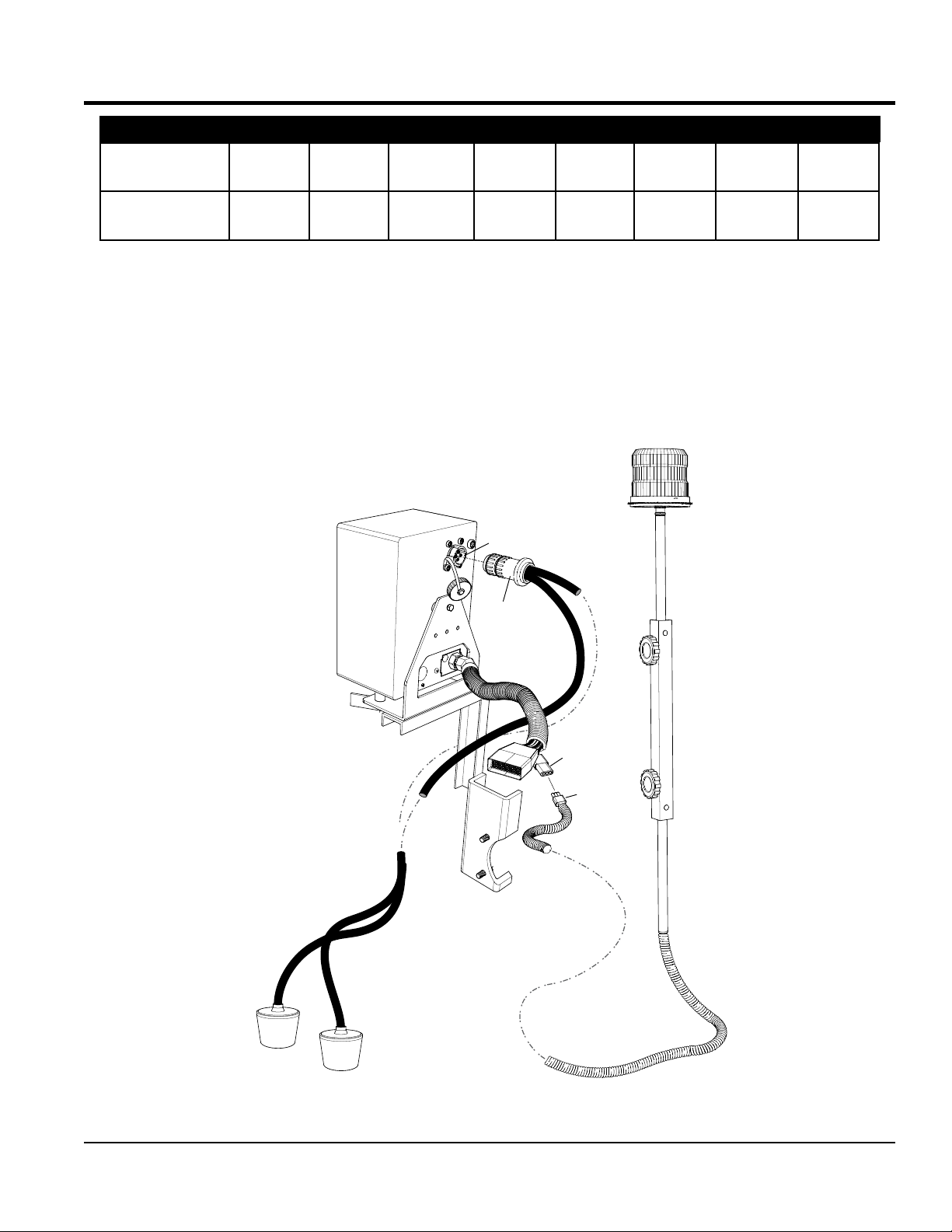
FLOAT SWITCHES/ALARM BEACON (AUTO MODE)
Table 7. Pumping Range
Tether Length
in. (cm.)
Pumping Range
in. (cm.)
2
(5.08)
6 in.
(15.24)
4
(10.1)
10
(25.4)
6
(15.24)
14
(35.56)
Mounting The Float Switches
1. Determine the required cord tether length as shown
in Figure 11 and Table 7.
2. Place the cord into the clamp as shown in Figure 11.
3. Secure the clamp to the suction hose as shown in. DO
NOT install cord under hose clamp.
REAR VIEW OF CONTROL BOX
8
(20.32)
(18)
(45.72)
10
(25.4)
22
(55.88)
12
(30.48)
27
(68.58)
14
(35.56)
31
(78.74)
(40.46)
(88.9)
4. Using a screwdriver, tighten the hose clamp. DO NOT
over-tighten. Make sure the float cord is not allowed to
touch the excess hose clamp band during operation.
Float Switch/Alarm Beacon Connections
Connect the float switches and alarm beacon to the control
box as shown in Figure 14.
ALARM BEACON
4-PIN FLOAT SWITCH
RECEPTACLE
FLOAT SWITCH
CABLE
16
35
BEACON
RECEPTACLE
BEACON
PLUG
FLOAT
SWITCH #2
FLOAT
SWITCH #1
Figure 14. Float Switches/Alarm Beacon Connections
AP6/AP8 SERIES TRASH PUMPS • OPERATION AND PARTS MANUAL — REV. #0 (06/11/14) — PAGE 27
Page 28
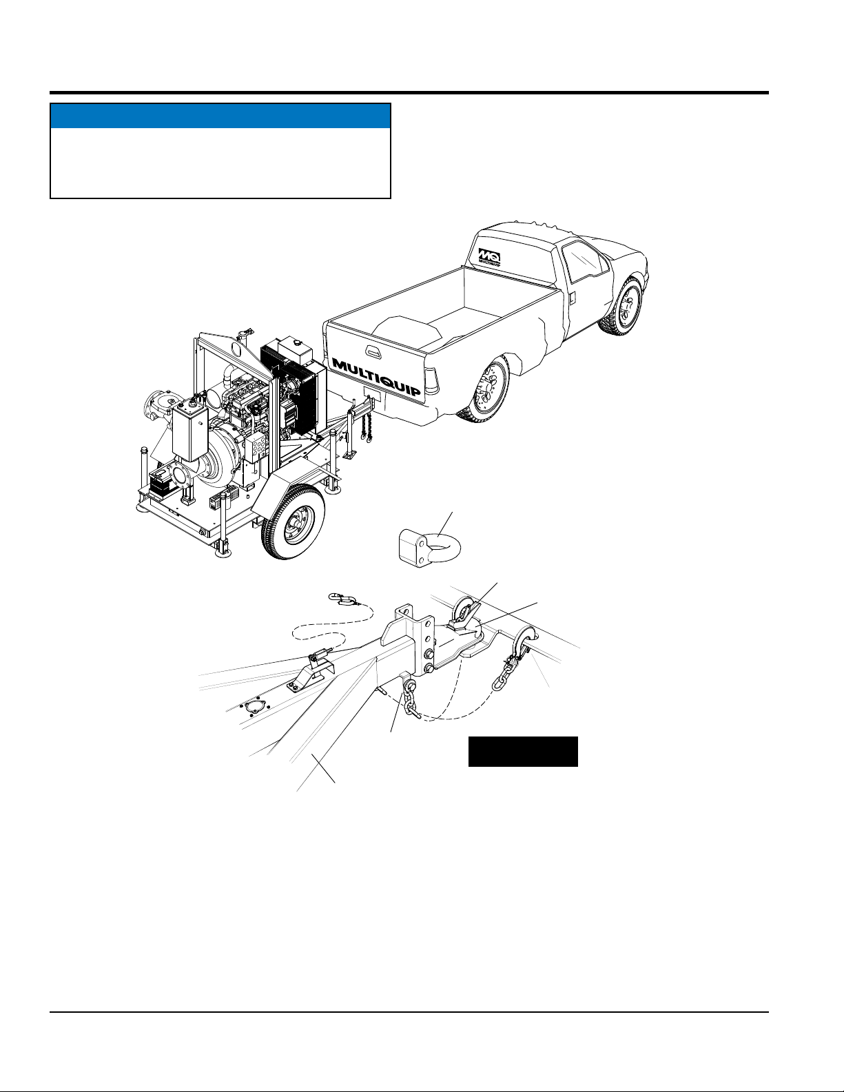
NOTICE
Reference Trailer Safety Guidelines section in this
manual for a more detailed complete understanding
on towing requirements.
TOWING APPLICATION
PINTLE
COUPLER
BALL
COUPLER
LOCK
LATCH
SAFETY CHAIN
MASTER LINK
TRAILER
TONGUE
IMPORTANT!
CROSS BOTH
SAFETY CHAINS
Figure 15. Towing Application
2-5/16”
BALL
COUPLER
SAFETY CHAIN
HOOK
PAGE 28 — AP6/AP8 SERIES TRASH PUMPS • OPERATION AND PARTS MANUAL — REV. #0 (06/11/14)
Page 29
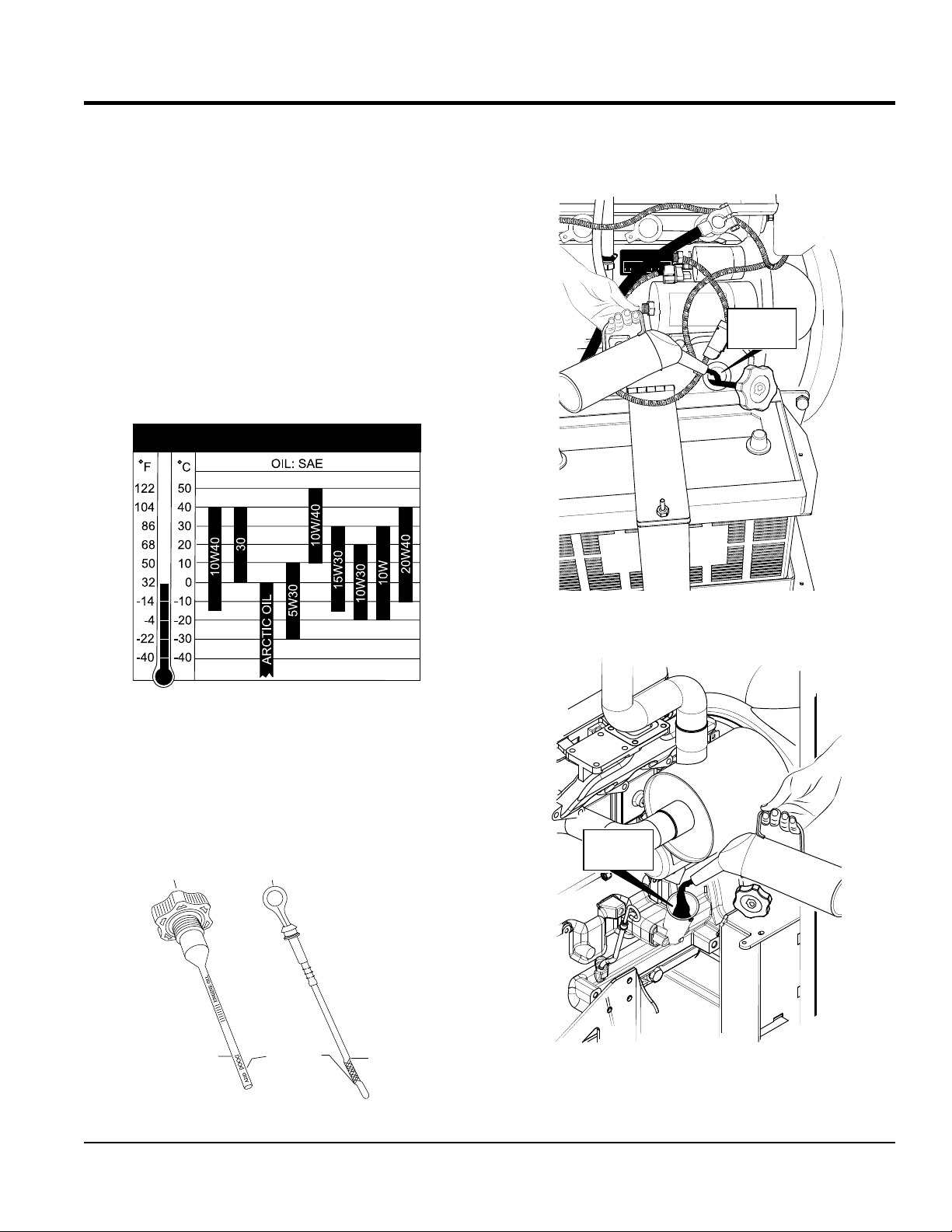
INSPECTION/SETUP
TING
AP6 ENGINE
OIL
ENGINE
OIL
FILLER HOLE
ENGINE OIL
When checking the engine oil, be sure to check if the oil is
clean. If the oil is not clean, drain the oil by removing the
oil drain plug, and refill with the specified amount of oil as
outlined in Table 3 or the John Deere Engine Owner’s
Manual. Oil should be warm before draining.
Other types of motor oils (Table 8) may be substituted if
they meet the following requirements:
API Service Classification CJ-4
API Service Classification CI-4
API Service Classification CI4 Plus
API Service Classification CH-4
ACEA Oil Sequence E3
Table 8. Recommended Motor Oil
4. If engine oil is low, fill engine crankcase with lubricating
oil through filler hole (Figure 17 and Figure 18, but
DO NOT overfill.
JOHN DEERE
ENGINE
OIL
FILLER HOLE
Checking Engine Oil
1. Make sure pump is placed on secure level ground.
2. Remove the engine oil dipstick from its holder.
3. Verify that the oil level (Figure 16) is maintained
between the two notches on the dipstick.
AP8 ENGINE
OIL DIPSTICK
ADD
ENGINE OIL
SAFE
OPERA
OIL LEVEL
DIPSTICK
SAFE
OPERATING
OIL LEVEL
Figure 17. AP6 Engine Oil Filler Hole
Figure 18. AP8 Engine Oil Filler Hole
Figure 16. AP6/AP8 Engine Oil Dipstick
AP6/AP8 SERIES TRASH PUMPS • OPERATION AND PARTS MANUAL — REV. #0 (06/11/14) — PAGE 29
Page 30
INSPECTION/SETUP
FUEL CHECK
DANGER - Fire/Explosion
NEVER fill the fuel tank while the engine
is running or in the dark. Fuel spillage on
a hot engine can cause a fire or explosion.
If fuel spillage occurs, wipe up the spilled
fuel completely to prevent fire hazards.
1. The fuel tank used with this pump has a built in fuel
gauge (Figure 19) within the tank. Read the fuel gauge
to determine if the fuel level is low.
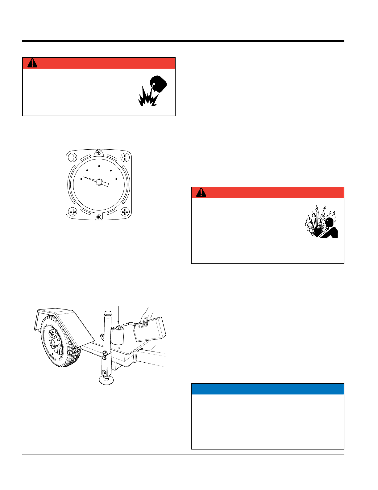
1/2
E
Figure 19. Fuel Gauge
2. Handle fuel in a safety container. If the container does
not have a spout use a funnel.
F
BATTERY CABLE CONNECTION
ALWAYS make sure the battery cables are properly
connected to the battery terminals. The RED cable is
connected to the positive terminal of the battery, and the
BLACK cable is connected to the negative terminal.
PUMP PLACEMENT
1. Read safety instructions at the beginning of manual.
2. Place pump on secure level ground as near to the
water as possible.
3. Deploy all four trailer jack stands to level the pump. If
possible place chock blocks underneath each wheel
to prevent the pump from rolling.
SUCTION/DISCHARGE HOSES CONNECTIONS
DANGER -High Pressure
PVC discharge hoses and thin-walled
rubber hoses can easily fail at the end
of the hose fittings. Leaks from the
hoses can cause high-pressure liquid
to be discharged, causing dangerous
conditions. Make sure pressure rating of hoses exceeds
the pump maximum pressure to prevent hose failure.
3. If the fuel level is low, fill (Figure 20) with recommended
type diesel fuel as referenced in Table 3. DO NOT fill
fuel tank beyond capacity.
FUEL FILLER
PORT
DIESEL FUEL
Figure 20. Refueling
4. Pay attention to the fuel tank capacity when replenishing
fuel. Refer to the fuel tank capacity listed in Table 4,
Trailer Specifications.
5. Tighten fuel tank cap securely after filling.
1. Check that the suction and discharge hoses (Figure 21)
are securely attached to the pump via Bauer™couplers
and are not restricted.
2. Place each hose so that it lays as straight as it is
possible on the ground. Remove any twists or sharp
bends from hose which may block the flow of water.
3. If using a light weight discharge hose, it should be
anchored to avoid movement with high flow or high
pressure water. Always use a suction hose or pipe that
matches the size of the pump inlet to insure optimum
performance and reduce the risk of damage to the
pump.
NOTICE
If.t is recommended that the discharge hose or pipe
match the size of the pump outlet to reduce friction as
much as possible. Using a discharge line that is larger
than the pump outlet will reduce friction and improve
water flow. Similarly, a smaller line will reduce water
flow by increasing friction.
PAGE 30 — AP6/AP8 SERIES TRASH PUMPS • OPERATION AND PARTS MANUAL — REV. #0 (06/11/14)
Page 31

FEMALE FLANGE
DISCHARGE HOSE
(THREADED)
MALE FLANGE
FEMALE FLANGE
INSPECTION/SETUP
GALVANIZED MALE
(THREADED)
INTAKE HOSE
FITTING
DISCHARGE SIDE
CHOCK BLOCK
Figure 21. Hose Connections
4. Shorter suction lift and suction hose length will produce
better performance.
FITTING
SUCTION SIDE
STRAINER
5. Remember suction hoses must be rigid enough not to
collapse when the pump is in operation.
6. Make sure the suction strainer is clean and securely
attached to the water end of the suction hose. The
strainer is designed to protect the pump by preventing
large objects from being pulled into the pump. Failure
NOTICE
Suction and discharge hoses are available from
Multiquip. Contact your nearest dealer for more
information.
DANGER - Flammable Fluids
to use a strainer could cause damage to the pump,
impeller, pump shaft, pump bearings, or wear plate.
DO NOT pump flammable fluids, corrosive chemicals or
fluids containing toxic substances. These fluids can create
7. If a strainer becomes clogged with debris, clean the
strainer.
potentially dangerous health and environmental hazards.
Contact local authorities for assistance.
CAUTION - Strainer Placement
The strainer should be positioned so it will remain
completely under water. Running the pump with the
strainer above water for long periods can damage the
pump.
AP6/AP8 SERIES TRASH PUMPS • OPERATION AND PARTS MANUAL — REV. #0 (06/11/14) — PAGE 31
Page 32

ENGINE STARTUP (MANUAL MODE)
IGNITION
1. Insert ignition key into ignition switch.
OPERATION (MANUAL MODE)
LOCK KNOB
SWITCH
AUTO START
(WHEN EQUIPPED)
IGNITION
KEY
Figure 22. Ignition Switch/Key
OFF
RUN
START
2. Turn ignition key to the RUN position, and verify that
voltmeter gauge on the control box indicates 12 VDC.
3. Verify that the battery, glow plug, oil pressure and
coolant temperature status LEDs are all ON.
4. Next, continue turning the ignition key clockwise and
place in the START position.
5. Release ignition key as soon as engine starts, and
verify that ignition switch automatically returns back
to the RUN position.
UNLOCK
LOCK
DECREASE
INCREASE
THROTTLE CONTROL
Figure 23. Throttle Control
NOTICE
If engine does not start, turn ignition key to the OFF
position to reset. Wait 10 seconds before restarting.
Use hand fuel pump to remove air from fuel return line.
Operation
1. The pump should begin pumping water within a minute
depending on the length of suction hose and height
the pump is above water.
6. Verify that the all status LEDs are OFF.
7. If battery charge indicator LED remains ON, increase
engine speed until LED goes OFF. When the charge
NOTICE
Longer suction hoses will require more time for the
pump to begin pumping water.
LED turns OFF, it can then be assumed that the
charging system is working correctly.
8. If the charge LED remains ON while the engine is
running, refer to Engine Troubleshooting Table or the
John Deere Engine Service Manual.
9. Unlock the throttle control lock knob (Figure 23) by
turning the knob counterclockwise.
10. Next, adjust the engine speed by turning the throttle
control clockwise to increase engine speed and
counterclockwise to reduce engine speed.
11. Once the desired engine speed has been achieved,
turn the throttle control lock knob clockwise to lock the
selected engine speed setting.
2. If pump does not begin to pump water after a few
minutes, check for loose connections or air leaks
in the suction hose. Make sure there is water in the
vacuum system and strainer is not clogged with debris.
Reference Pump Troubleshooting Flowchart.
3. Make certain suction hose does not have any air
leakage. Tighten hose clamps and couplings as
required.
4. Check for leaks between pump and engine. If water
is leaking between the pump and bearing housing,
the seal inside the pump may be worn or damaged.
Continued operation of the pump is not recommended.
Further usage of the pump under these conditions
may cause severe water damage to bearing housing
assembly.
PAGE 32 — AP6/AP8 SERIES TRASH PUMPS • OPERATION AND PARTS MANUAL — REV. #0 (06/11/14)
Page 33

OPERATION (MANUAL MODE)
Engine Shut-Down
1. Place engine throttle control in the idle position and
place the ignition key in the OFF position.
CAUTION -Disconnecting Discharge Hose
If pumping in a positive head (pumping up hill), be
sure to open discharge check valve drain and release
pressure before uncoupling hose.
Pump Inspection After Use
2. It is recommended that the pump be inspected after
each use for damage or wear.
3. Drain and flush pump volute and priming system from
suction end.
4. Inspect impeller for wear or damage and measure
impeller clearance if it appears worn. Inspect interval
should be about every 1000 hours. This inspection
should be done when the pump is scheduled for
maintenance inspection.
5. Inspect discharge check valve for wear or damage.
Replace if necessary.
Pump Storage
For storage of the pump for over 30 days, the following is
required:
Drain the fuel tank completely.
Run the engine until the fuel in the injection system is
completely consumed.
Completely drain used oil from the engine crankcase
and fill with fresh clean oil, then follow the procedures
described in the engine manual for engine storage.
Remove the drain plug from the pump and drain out any
water from left in the housing.
Remove the pump cover and clean inside of pump
housing. Coat inside of pump housing with a light film
of oil to reduce corrosion. A spray can of oil works well
for this application.
Cover suction and discharge ports with duct tape to
prevent any foreign matter from falling into pump.
Cover pump and engine with plastic covering or
equivalent and store in a clean, dry place.
6. Inspect fuel tank and check for water by removing 0.5inch drain plugs. Do not overtighten when replacing.
7. Check oil reservoirs for contamination or water.
8. Do dry vacuum test to check seal and check valve
seal. This check should be done when the pump is
scheduled for maintenance inspection.
AP6/AP8 SERIES TRASH PUMPS • OPERATION AND PARTS MANUAL — REV. #0 (06/11/14) — PAGE 33
Page 34

OPERATION (AUTO MODE)
3
2
AUTO MODE
Both the AP6 and AP8 series pumps have an optional
auto-start controller (MS-200). This controller allows for a
float switch capability which is designed for the automatic
start-stop of the pump. Additionally, audible and visual alerts
signal engine restarting through a control box alarm and
beacon attachment.
MSS 200 AUTO START CONTROLLER
NOTICE
The MSS-200 is a dual function controller, meaning it
can be used for generator or pump applications. When
programming the various operating parameters use
pump related parameters only (pump mode).
The MSS-200 is an automatic engine start stop controller.
The MSS-200 is fully programmable. Its 15 parameters
are pre-programmed at the factory to the most commonly
used parameters. Changing the factory preset, however, is
easily accomplished by pushing three buttons (Figure 24)
on the front of the face of the controller.
FLOAT SWITCHES
Two pairs of normally open float switch contacts (high/low)
are provided with the auto-start controller. The controller is
pre-wired for the floats, utilizing a 4-pin connector located
at the rear of the control box.
PARAMETERS
NOTICE
Refer to the programming section of this manual
when changing any of the factory preset parameters
is required.
Preheat Parameter
The duration period of preheat can be programmed by time
(in 4 second increments) or by ambient temperature if used
in combination with a PT-1000 thermistor or equivalent.
The preheat time setting, has priority over ambient
temperature. In case of a defective thermistor or loose
wire connection, it is important that a time value is always
programmed when used in combination with a thermistor.
When using the temperature thermistor provision, use
Table 9 for temperature verses time comparison.
1
Figure 24. MS-200 Controller Buttons
Automatic Shutdowns
When used in combination with ground contact switches,
the MSS-200 can also shutdown the engine. The control
box allows for the wiring and automatic shutdown of the
engine for the following parameters:
High Oil Pressure 150 psi (1,034 kPa)
High Coolant Temperature 220~230°F (102~112°C)
Alternator Charge
Broken V-Belt
Engine Overspeed
Other Customer Defined Parameters
Table 9. Preheat Parameter #0
°F °C
+122 +50 0 0
+104 +40 4 4
+68 +20 6 4
+32 0 12 6
-4 -20 22 6
-40 -40 30 6
The preheat function on the MSS-200 can also be used in
combination with a pre-start audible alarm. Simply program
a preheat duration and add an alarm to the preheat output
to provide additional safety to your equipment. Alarms are
available as an option.
Preheat
Time (sec.)
After-Glow
Time (sec.)
PAGE 34 — AP6/AP8 SERIES TRASH PUMPS • OPERATION AND PARTS MANUAL — REV. #0 (06/11/14)
Page 35

OPERATION (AUTO MODE)
F
Repeated Engine Starts Parameter
If the engine does not start on the first auto start attempt,
the engine will go into repeat start mode. The MSS-200
can be programmed to make a maximum of 15 new
engine start attempts. During repeated starts the bottom
left LED (Figure 25) will blink, indicating that the system is
in repeated start mode.
AUTO LED FLASHING OR OF
ENGINE WILL NOTSTA RT
LED IS FLASHING
REPEATED START MODE
Figure 25. Repeated Start Mode LED (Flashing)
NOTICE
Engine will not go into repeated start mode if the engine
is started manually by pressing the MAN button.
Pause Between Repeated Engine Starts Parameter
NOTICE
The cool-down cycle can only be used when the
controller’s standby mode (parameter 30) is programmed
to consume electricity.
Oil Pressure Switch Parameter
This parameter is used to select the type of oil pressure
switch being used on the engine, i.e., normally closed (NC),
normally open (NO) or no oil pressure switch.
The no oil pressure switch setting must be selected
when the MSS-200 is used in combination with any other
auxiliary engine monitored and shutdown system, i.e., EP100, MC-536 or MC-6K.
In the solo mode the MSS-200 can also be programmed
to monitor oil pressure. This feature adds starter motor
protection by preventing the starter motor from engaging
when the engine has oil pressure, or if the pressure switch
wire has been disconnected.
Applications requiring shutdown for other critical functions
like high temperature or pump pressure can connect the
switch wires to the oil pressure input.
Pause between repeated engine start is the period between
each repeated start-up attempt. The range for this pause is
between 5~75 seconds in 5 second increments.
Overcrank Parameter
Overcrank is defined as the maximum time, in seconds,
that the starter motor can be engaged if the engine fails to
receive a frequency via the alternator’s frequency terminal
or proximity switch pick-up.
The over crank feature eliminates the need for any manual
settings of starter motor duration usually required for low
temperature conditions.
Engine Cool-Down Cycle Parameter
This parameter controls the length of time in which the
engine is in its cooling-down cycle. Once the ground contact
is removed from the AUTO terminal wire, the MSS-200 will
shut off throttle control or compressor.
The engine will run without load for an amount of time
established by the customer. Cool-down cycle time can be
programmed from 0~900 seconds in 60 second increments.
NOTICE
Connecting a small jumper wire from the overspeed
(O/S) terminal to the OEL (oil) terminal eliminates the
need for adding an extra relay for overspeed shutdown.
Oil Pressure Switch Time Delay Parameter
With this parameter a delay of 1 to 15 seconds can be
programmed for oil pressure switch override. This feature
gives the engine a certain amount of time to build up
oil pressure during engine start prior to monitoring for
shutdown.
This parameter is required only when the MSS-200 is used
in solo mode and when the oil pressure parameter #12 is
programmed to either a normally open or normally closed
switch contact.
Auxiliary Engine Monitor Parameter
This parameter programs the MSS-200 controller to either
a stand-alone application (solo) or to an application utilizing
an optional engine shutdown device, i.e., EP-100, MC-536
or MC-6K.
AP6/AP8 SERIES TRASH PUMPS • OPERATION AND PARTS MANUAL — REV. #0 (06/11/14) — PAGE 35
Page 36

6 x 500 x 2
6000
60 Seconds
60
: 1800 RPM Engine Engagement
PRESS TO SAVE VALUE
OPERATION (AUTO MODE)
EXAMPLE: 360-240 = 120 (Balance)
120
12 Hz = 352 Hz
360 Hz - 352 Hz =
8 Hz
60 Seconds
60
Duration of Start By Frequency Parameter
The MSS-200 will disengage the starter motor when the
engine has reached a certain programmed frequency via
the frequency terminal of the alternator or proximity switch
(PNP).
This feature not only disengages the starter motor, but it
is also used as a safety feature by preventing the engine
from starting when the controller senses RPM.
Considering that a starter motor typically disengages at 500
RPM, use the following calculation below using an engine
with a 6 pole pair alternator and a belt ratio of 2:X where:
X
=
60 Seconds
=
60
100 Hz
=
Pump Overspeed Shutdown (Course) Parameter
1. Parameters 20, 22, and 24 provide overspeed
shutdown for variable speed pump applications.
EXAMPLE
6 x 1800 x 2
X
=
=
21600
360 Hz
=
2. For parameter 20 select the next smaller number
calculated. In our example we calculated 360 Hz. The
next smaller number on the programming table is
240 Hz. Press the AUTO button until the LED pattern
matches the 240 Hz value.
Pressing the OFF/SET button (Figure 26) saves the
programmed value and moves you to parameter 22.
Pump Overspeed Shutdown (Medium) Parameter
Subtract the frequency value entered in step 2 from the
total frequency calculated from step 1.
3. Divide the balance by the multiplier 16. Since you can
not use a fraction use the next smaller number (7) and
multiply by the multiplier (16) which in this example is
112 Hz. With this example, select the LED pattern that
matches 112 Hz.
7.57.5 7x16 = 112 Hz
=
16
Pump Overspeed Shutdown (Fine) Parameter
4. Subtract 360 Hz from the total sums entered in steps 1
and 2. The multiplier for step 3 equals 1 Hz. Parameter
24 would be programmed to 8 Hz.
240 Hz + 1
Variable Speed Pump Mode Selection Parameter
1. Entering a value greater than zero programs the MSS200 controller to a constant engine speed mode. The
frequency programmed in parameter 26 then becomes
the overspeed shutdown frequency.
Should the engine speed mode not require overspeed
protection, then parameter 26 should be programmed
to the highest overspeed frequency setting available
(150 Hz). Use the following 2000 RPM calculation
to program overspeed for a constant engine speed
application:
EXAMPLE: Calculating Overspeed (Hz)
Figure 26. SET Button (Saving Data)
PAGE 36 — AP6/AP8 SERIES TRASH PUMPS • OPERATION AND PARTS MANUAL — REV. #0 (06/11/14)
6 x 2000 x 2
=
24000
400 Hz
=
Subtract 360 (total Hz of G/S in step #20, 22 and 24)
from 400 Hz (Over-Speed Hz) 400 – 360 = 40 Hz.
The multiplier for parameter 26 equals 10. Press the
AUTO or MAN buttons until the LED pattern matches
the 40 Hz value.
Page 37

MODE
OPERATION (AUTO MODE)
3
AUTO LED ON
2. Programming parameter 26 to zero programs the
MSS-200 for variable speed pump application with
overspeed. The frequency programmed in parameters
20, 22 and 26 then become the RPM at which the
engine will shutdown.
NOTICE
When the MSS-200 is programmed in pump mode
overspeed shutdown delay becomes a fixed zero
second delay.
Engine Warm Up Duration Parameter
When the application is a variable speed pump with
overspeed, this parameter can be used as a warm-up
period from 8 to 38 seconds in 2 second increments.
Standby Mode Parameter
Standby mode on the MSS-200 can be programmed to
either to consume electricity or to consume no electricity.
In the standby mode that consumes electricity, the
controller is activated by a ground contact to the AUTO
terminal and deactivated when ground from the AUTO
terminal is removed.
During standby mode, the top right AUTO LED (Figure 27)
is lit indicating that the unit is in standby mode.
STANDBY
Basic Operation
The MSS-200 can be controlled directly from the face of
the MSS-200 controller by simply pushing either MAN OFF/
SET, and AUTO buttons (Figure 28).
2
1
Figure 28. MSS-200 Control Buttons
Only when the MSS-200 is powered up and parameter
30 (standby mode) has been programmed to consume
electricity will the AUTO and MAN buttons control the
engine. Pressing the MAN button manually starts the
engine. Engine will continue to run until the OFF/SET button
is pressed again or until the power is turned off.
If parameter 10 (cool down cycle) is programmed with a
cool down cycle time, pressing the OFF/SET button once
will start the cool down cycle. Pressing the OFF/SET button
again will override the cool down cycle and the engine will
shut down immediately.
Pressing the AUTO button (Figure 29) will cause the AUTO
LED to light up, indicating that the engine is in standby
mode.
STANDBY MODE
Figure 27. Standby Mode (Auto)
In the standby mode that does not consume electricity,
the MSS-200 is activated when the unit receives a battery
plus signal. When battery positive signal is removed, the
engine will shut down immediately.
Figure 29. Auto LED ON (Standby Mode)
NOTICE
If the AUTO LED is not lit or flashing the engine will not
start automatically.
AP6/AP8 SERIES TRASH PUMPS • OPERATION AND PARTS MANUAL — REV. #0 (06/11/14) — PAGE 37
Page 38

F
OPERATION (AUTO MODE)
(BLINKING)
(BLINKING)
8 (OFF)
NOTICE
A blinking AUTO LED (Figure 30) during power up
indicates that the auto start input was activated and
prevents the engine from starting.
AUTO LED FLASHING OR OF
ENGINE WILL NOTSTART
Figure 30. Auto LED Blinking/OFF
LED Status
Table 10 shows the status of the LED's when programming.
Table 10. LED Definitions
LED
Status
Indicates a flashing LED and identifies
the parameter being programmed.
Description
Controller Display
The controller display face has 4 LEDs. Each LED has a
dual function. Function number 1 is to display the indicated
parameter Function number 2 is to display the set value of
the indicated parameter.
Example Function 1
As shown in Figure 31, parameter 6 (cool-down cycle)
has been selected LEDs 2 and 4 are blinking.
4
2
Figure 31. Parameter 6 Selection
Example Function 2
The cool-down cycle now needs to have a time duration
(0~900 seconds) programmed into the controller. To
accomplish this press the AUTO button on the controller
until 2 bottom LEDs are on (Figure 32).
8 (OFF)
1 (OFF)
NOTICE
There are 15 programmable parameters (Table 11).
These parameters can be displayed on the controller
in a binary pattern. Reference Table 12 (Programming
Guide) on how to program the parameters.
Indicates LED is ON, and identifies the
value of the parameter.
Indicates LED is OFF.
This produces a value of 3. This value multiplied by 60
(reference Table 12, engine cool-down) produces a total
cool-down duration period of 300 seconds (5 minutes).
Press the OFF/SET button to enter the value into the
controller.
(OFF) 4
(ON) 2
Figure 32. Parameter 6 Value
1 (ON)
PAGE 38 — AP6/AP8 SERIES TRASH PUMPS • OPERATION AND PARTS MANUAL — REV. #0 (06/11/14)
Page 39

LED's
Pre-Heat Duration
PROGRAMMING
Table 11. Programmable Parameters
4
8
1
2
4
8
2
1
4
2
8
1 2
8
4
1
4
2
8
4
1 1
2
8
4
2 1
8
4
8
1
2
Pause
Between
Repeated
Starts 5-75
Seconds
4
8
Overcrank
Seconds or
Frequency
Parameter
Preheat
0-60 Sec.
or Ambient
Temp.
4
8
Number
Repeated
Starts 0-15
4
8
LED's
2 1
12
2 1
Auxiliary
Turn On
Throttle
Control,
Compressor
etc.
Overspeed
Shutdown
Parameter
Engine
Monitor
EP100,
MC536,
Starter
Motor
Disengage
Hz.
Solo
PROGRAMMING
1. Programming is accomplished by holding down the
OFF/SET button (Figure 33) on the MSS-200 for 2
seconds while energizing the controller. Energizing
the MSS-200 controller is accomplished by turning the
ignition key to the left position marked “Auto Start”.
2-30
8
4 8
2 1
N/A
4
2
Overspeed
Shutdown
Hz
Delay
Seconds
1
Engine
Cool-Down
Cycle
0-900
Seconds
8
4
1
2
Engine
Warm-Up
Duration
8-38
Seconds
Oil
Pressure
Switch NC,
NO, No
Switch
84
2 1
Standby
Mode
Consume
Electricity
Yes/No
Oil
Pressure
Delay
Override
1-15 Sec.
84
2 1
Pass Code
#3 Digit
0-15
BLINKING
OFF
AUTO START
(WHEN EQUIPPED)
RUN
Figure 34. Pre-Heat Duration (Blinking)
3. Pushing the OFF/SET button moves to each parameter
in ascending order and saves the programmed value.
PRESS AND HOLD
FOR 2 SECONDS
The MAN button decreases the programmed value
while the AUTO button increases the programmed
value.
Figure 33. MSS-200 Controller Initialization
2. Releasing the OFF/SET button will bring you to
parameter 0, preheat duration indicated by the
NOTICE
The cool-down cycle and manual start functions can not
be used in the consumes-no-electricity mode.
flashing of LED 1 (Figure 34).
AP6/AP8 SERIES TRASH PUMPS • OPERATION AND PARTS MANUAL — REV. #0 (06/11/14) — PAGE 39
Page 40

Pass Code
DIGIT 1)
(PASS CODE DIGIT 2)
OFF
(PASS CODE DIGIT 3)
PROGRAMMING
The MSS-200 controller allows the user to input a 3-digit
pass code to prevent unauthorized personnel from
changing any of the controller's parameters.
However, the factory set pass code does not prevent
unauthorized personnel from changing any of the
controller's parameters. Entering a user-defined pass code
for the first time requires entering the factory-set pass code
of 0, 0, 0.
Entering Factory Pass Code (First Time)
5. Press the OFF/SET button (Figure 37) one last time
this will enter the value zero for pass code digit 3 into
the controller.
BLINKING
(PASS CODE
DIGIT 3)
BLINKING
1. Push the AUTO and OFF/SET buttons at the same
time while turning the ignition key to the auto position.
2. As soon as the two buttons are released, LED 1 blinks
indicating pass-code digit 1.
NOTICE
Please note that the LED 1 indication is the same as the
preheat duration parameter; however since the AUTO
and MAN buttons were pushed at the same time, this
parameter is now pass-code.
3. Press the OFF/SET button (Figure 35) this will enter
the value zero for pass code digit 1 into the controller.
OFF
OFF
Figure 35. Pass Code Digit 1
OFF
ON
(PASS CODE
4. Press the OFF/SET button (Figure 36) again this will
enter the value zero for pass code digit 2 into the
controller.
Figure 37. Pass Code Digit 3
6. Observe that LED 1 starts blinking (Figure 34),
indicating preheat duration parameter. From this
point if you wish to enter a user defined pass code,
press the OFF/SET button 32 times and perform the
procedure shown in Changing Factory Pass Code
section in this manual.
Changing Factory Pass Code
NOTICE
See Table 12 (Programming Guide), reference steps
32, 34 and 36.
To change the factory pass code to a user defined pass
code perform the procedure below:
1. Press the OFF/RESET button 32 times. Reference
steps 32, 34 and 36 (number of pushes of OFF/SET
button) in Table 12, Program Guide.
2. Press the OFF/SET button and select the first pass
code value (0 – 15) using the AUTO and MAN buttons.
3. Repeat this procedure until all 3 pass code numbers
are entered.
End Programming
OFF
BLINKING
Figure 36. Pass Code Digit 2
PAGE 40 — AP6/AP8 SERIES TRASH PUMPS • OPERATION AND PARTS MANUAL — REV. #0 (06/11/14)
OFF
The programming mode can be terminated at any time
simply by removing power from the MSS-200 or by going
to the last parameter (Standby Mode, 30). As long as the
OFF/SET button is pressed the last programmed value will
be saved in memory.
Page 41

Reference Table 12 when programming of the MSS-200
is required.
Table 12. Programming Guide
Number Of
Pushes Of
OFF/SET
Button
Button To
Push
Parameters LED Multiplier
PROGRAMMING GUIDE
Factory
Setting
Range
Decrease
Value
Increase
Value
OFF/SET
Ignition Key
0 OFF/SET
OFF/SET
2 OFF/SET
OFF/SET
4 OFF/SET
OFF/SET
Turn On
System
Preheat
Duration
Input:
Time Seconds
Repeated
Starts
Input: Number
Starts
Pause
Between Starts
Input:
Time Seconds
418
2
4
2
4
2
4
2
4
2 1
4
2 1
8
1
84
4 0 Seconds 0~60 Seconds (-) MAN (+) AUTO
12
8
1
8
1 3 0~15 (-) MAN (+) AUTO
1
8
8
5 5 Seconds 5~75 Seconds (-) MAN (+) AUTO
8
4
6 OFF/SET Overcrank
2
1
8
OFF/SET
10 OFF/SET
OFF/SET
Input:
Time Seconds
Engine Cool-
Down Cycle
Input:
Time Seconds
4
2 10 Seconds 2~30 Seconds (-) MAN (+) AUTO
2
1
8
4
2
1
84
60 0 Seconds
12
0~900
Seconds
(-) MAN (+) AUTO
AP6/AP8 SERIES TRASH PUMPS • OPERATION AND PARTS MANUAL — REV. #0 (06/11/14) — PAGE 41
Page 42

Number Of
PROGRAMMING GUIDE
Pushes Of
OFF/SET
Button
12 OFF/SET
Button To
Push
Table 12. Programming Guide (Continued)
Parameters LED Multiplier
4
Oil Pressure
Switch
8
12
Factory
Setting
Range
Decrease
Value
Increase
Value
OFF/SET
OFF/SET
OFF/SET
14 OFF/SET
OFF/SET
16 OFF/SET
OFF/SET Solo
Input:
Type
Oil Pressure
Delay
Input:
Time Seconds
Aux. Engine
Monitoring
84
None None 0-1-2
12
4
8
1
2
4
8
1
2
8
4
2
1
8
4
Normally
Closed (NC)
Normally
Open (NO)
0-1-2 (-) MAN (+) AUTO
0-1-2 (-) MAN (+) AUTO
1 8 (-) MAN (+) AUTO
2
1
8
4
1
2
84
0-1
12
18 OFF/SET
20
Coarse RPM
Setting, Step 1
OFF/SET
OFF/SET
OFF/SET
Option Engine
Monitoring
Device
Duration Of
Start By Freq.
(Alt./Pickup)
Input:
Frequency (Hz)
Pump Mode
Overspeed
8
4
1
2
8
4
2
1
8
4
Optional
Device
0-1 (-) MAN (+) AUTO
16 96 Hz 1~240 Hz (-) MAN (+) AUTO
2
1
4
8
12
Note:
For over speed shutdown for variable speed pump applications, parameter 26 must be programmed to zero "PUMP MODE". In pump mode overspeed
shurdown delay is a fixed zero second delay.
PAGE 42 — AP6/AP8 SERIES TRASH PUMPS • OPERATION AND PARTS MANUAL — REV. #0 (06/11/14)
Page 43

Number Of
PROGRAMMING GUIDE
Pushes Of
OFF/SET
Button
Button To
Push
Table 12. Programming Guide (Continued)
Parameters LED Multiplier
Factory
Setting
Range
Decrease
Value
Increase
Value
22
Medium RPM
Setting, Step 2
24
Fine RPM
Setting, Step 3
26 OFF/SET Pump Mode
28 OFF/SET
OFF/SET
OFF/SET
OFF/SET
OFF/SET
OFF/SET Pump Mode
Pump Mode
Overspeed
Input:
Frequency (Hz)
Pump Mode
Overspeed
Input:
Frequency (Hz)
Pump Mode
Warm-up
Period (Sec.)
84
1
2
84
12
84
1
2
84
12
84
12
84
12
84
12
16 0 Hz 1~240 Hz (-) MAN (+) AUTO
1 0 Hz
1 0 Hz 1~15Hz (-) MAN (+) AUTO
Pump Mode (-) MAN (+) AUTO
Refer To
Parameter 26
OFF/SET
30 OFF/SET Standby Mode
OFF/SET
OFF/SET
Input:
Time Seconds
Consumes
no electricity.
Immediate
Start With
Current
Consumes
Electricity.
84
12
84
1
2
84
12
84
1
2
2 8 sec 8~38 Seconds (-) MAN (+) AUTO
Manual or
automatic
start when
system is
grounded
0-1
(-) MAN (+) AUTO
(-) MAN (+) AUTO
AP6/AP8 SERIES TRASH PUMPS • OPERATION AND PARTS MANUAL — REV. #0 (06/11/14) — PAGE 43
Page 44

Table 12. Programming Guide (Continued)
PROGRAMMING GUIDE
Note:
When the MS-200 is programmed in STANDBY MODE which does not consume electricity, the AUTO input terminal on the MSS-200 must be connected to a
ground at all times.
Number Of
Pushes Of
OFF/SET
Button To
Push
Parameters LED Multiplier
Factory
Setting
Range
Decrease
Value
Increase
Value
Button
8
32 OFF/SET Pass Code
4
1
2
Input:
OFF/SET
34 OFF/SET Pass Code
OFF/SET
36 OFF/SET Pass Code
OFF/SET
First Digit
Value
Input:
Second Digit
Value
Input:
Third Digit
Value
84
12
8
4
1
2
84
12
8
4
12
84
12
1 0 0~15 (-) MAN (+) AUTO
1 0 0~15 (-) MAN (+) AUTO
1 0 0~15 (-) MAN (+) AUTO
PAGE 44 — AP6/AP8 SERIES TRASH PUMPS • OPERATION AND PARTS MANUAL — REV. #0 (06/11/14)
Page 45

MSS-200 DIAGNOSTICS (AUTO MODE)
Reference Table 13 for a brief explanation of the LED status
indicators when MSS-200 is in AUTO mode.
Table 13. MSS-200 LED Status Auto Mode
LED's Description
4 8
Automatic self test. The MSS-200 is turned on. System is energized.
12
84
MSS-200 is awaiting start signal via ground (switch contact is open). Changing to manual start
mode is possible by pressing the OFF/SET and then the MAN button.
12
4
8
Switch contact was closed while energizing the system. Pushing the AUTO or OFF/SET then
MAN button will start engine.
12
8
4
2
4
2
Engine is preheating.
1
8
Engine is starting.
1
84
Engine is in repeated start mode.
12
84
Engine is running. The AUTO LED is lit indicating that the engine was started automatically by
grounding the AUTO terminal.
12
8
8
While the engine was running, the switch contact was closed or the OFF/SET button was pushed
one time. Engine is in the cooling down cycle.
12
AP6/AP8 SERIES TRASH PUMPS • OPERATION AND PARTS MANUAL — REV. #0 (06/11/14) — PAGE 45
Page 46

MSS-200 DIAGNOSTICS (MANUAL MODE)
Reference Table 14 for a brief explanation of the LED status
indicators when MSS-200 is in MANUAL mode.
Table 14. MSS-200 LED Status Manual Mode
LED's Description
4 8
Automatic self test. The MSS-200 is turned on. System is energized.
12
84
The MSS-200 is in off position and is awaiting a manual start signal Pushing MAN button will
start engine. Changing to AUTO mode is possible by pressing the AUTO button.
12
8
4
2
4
2
4
2
Engine is preheating.
1
8
Engine is starting.
1
Engine is running via the manual mode. If programmed engine will go into cool down cycle when
8
the OFF/SET button is pushed 1 time. Engine will stop immediately when the OFF/SET button is
1
pushed 2 times.
4
8
Engine is the cooling down cycle. Engine will shut down after it runs without a load for the
programmed amount of time.
12
PAGE 46 — AP6/AP8 SERIES TRASH PUMPS • OPERATION AND PARTS MANUAL — REV. #0 (06/11/14)
Page 47

MSS-200 TROUBLESHOOTING
Reference Table 15 for basic troubleshooting solutions.
Table 15. MSS-200 Troubleshooting
LED's Symptom Possible Problem Solution
84
2 1
No oil pressure or overspeed
O/S to Oel jumper wire not connected?
Check jumper wire from
O/S to Oel terminal.
4
2
4
281
4
281
2841
241
Defective alternator or pick-
8
up, wire breakage or V-Belt
1
breakage.
Engine did not reach the
set engine speed within 30
seconds
Cannot read sensor inputs.
Incorrect alternator or oil
pressure switch reading
8
All engine start attempts
failed.
MS-200 is not receiving a frequency signal? Check wiring (input signal)
Is programmed value correct? Re-program value
Electrical short, wire breakage, or defective
transistor?
Check wiring, sensor
components.
Is programmed value correct? Re-program value
Defective fuel filter?
Empty fuel tank?
Clean or replace fuel filter.
Check fuel level.
AP6/AP8 SERIES TRASH PUMPS • OPERATION AND PARTS MANUAL — REV. #0 (06/11/14) — PAGE 47
Page 48

MAINTENANCE (PUMP)
-15
-30
-1
0
-5
in.Hg
kPa
WIKA
R
-100
-80
-60
-40
-20
PUMP VACUUM TESTER
25 IN.HG TRANSLATES
INTO 25 FEET OF LIFT
AT SEA LEVEL.
PLACE VACUUM TESTER
OVER PUMP INLET.
-25
-20
ACCEPTABLE READING
SHOULDBE BETWEEN
-27 AND -25 IN.HG.
(In. Hg=INCHES
OF MERCURY)
PUMP
VACUUM
TESTER
PUMP MAINTENANCE
To ensure longer pump life and service, please follow the
pump maintenance guidelines as listed in Table 16 and on
preceding pages.
Table 16. Pump Maintenance
Interval Check
Check bearing housing.
Check mechanical seal oil reservoir.
Check vacuum pump seal oil reservoir.
Daily
Every 250 Hours
Every 500 Hours
Every 1000 Hours
Every 2000 Hours Grease vacuum pump bearings.
Check water level in vacuum system and
anti-freeze concentration for weather
conditions.
Check for leaks and kinks in discharge hose.
Check pump volute. Flush with clean water.
Check strainer.
Check if water is clean and anti-freeze is right
for conditions in vacuum system.
Check oil reservoirs for bearings, pump seal
and vacuum pump seal for contamination,
drain, and replace if necessary.
Check impeller bolt for tightness.
Flush vacuum system water tank and fill with
clean water. Add antifreeze if necessary.
Check impeller condition and clearance. Adjust
clearance as needed.
Change oil in pump seal, pump bearing
housing, and vacuum pump seal reservoirs.
Inspect discharge check valve for wear.
Replace if necessary.
6. Shut off the engine and check the vacuum reading.
The vacuum reading should be .75 to .9 bar or 25 to
27 in. hg. Vacuum reading should hold for about 3 to
10 minutes before dropping to zero.
7. If vacuum reading drops fast, check for leaks and repair
if necessary. Listen for leaks. If area is quiet, small air
leaks should be easy to hear.
NOTICE
The vacuum test will indicate the condition on the
impeller and wear ring. If this test fails, the pump must
be disassembled, and the impeller and wear ring
must be inspected for wear and clearance tolerances.
Reference replacing the impeller procedure in the
maintenance section of this manual.
DRY PUMP VACUUM TEST
1. To perform the pump vacuum test do the following:
2. Perform all start-up steps without installing the hoses.
3. Block the suction with a plug or heavy rubber flap as
shown in Figure 38. An accurate vacuum gauge should
be installed in the plug or flap to check vacuum system
performance and pump vacuum gauge.
4. Place the ball valve on side of suction chamber in the
CLOSED position, this will isolate the venturi.
5. Start the engine and run at 1,800 RPM. Note the
maximum vacuum reading.
PAGE 48 — AP6/AP8 SERIES TRASH PUMPS • OPERATION AND PARTS MANUAL — REV. #0 (06/11/14)
Figure 38. Dry Pump Vacuum Test
Page 49

NOTICE
SQUARE HEAD
CLEAN-OUT
COVER
REMOVE
O-RING
REMOVE
REMOVE
BOLT
Before attemping any maintenance procedures on the
pump, ALWAYS disconnect the negative battery cable
from the battery.
Refer to the Pump End Assembly drawing in the parts
section of this manual for item numbers referenced in
the maintenance procedures shown below and on the
preeceeding pages.
PUMP FLUSHING
NOTICE
Proper pump care requires that the pump volute
chamber be flushed with clean fresh water, to ensure
that no corrosive liquids or potentially damaging
particles are left inside the pump during idle periods.
1. Remove the 3 square head vent plugs (Figure 39)
from the volute.
MAINTENANCE (PUMP)
Figure 40. Clean-Out Cover Removal
4. Place the volute drain valve (Figure 41) in the OPEN
position.
PLUG (3)
REMOVE
2. Remove the bolts (2) that secure the clean-out cover
(Figure 40) volute casing.
3. Remove clean-out cover and o-ring.
Figure 39. Plug Removal (2)
VOLUTE
CLOSED
OPEN
VOLUTE DRAIN
VALVE
Figure 41. Volute Drain Valve (Open)
5. Flush the pump from the discharge side, using a high
velocity stream of fresh water.
6. Continue flushing until clear water comes out of each
drain plug, especially the bottom drain valve.
7. Reinstall the 3 square head vent plugs.
8. Reinstall the cleanout cover on the volute.
9. Place volute drain valve in the CLOSED position.
AP6/AP8 SERIES TRASH PUMPS • OPERATION AND PARTS MANUAL — REV. #0 (06/11/14) — PAGE 49
Page 50

VACUUM
MAINTENANCE (PUMP)
E
CHAMBER
ASSEMBL
Testing the Venturi Nozzle
1. Using a flat blade screw driver, disconnect the hose
(Figure 42) connected to the suction chamber ball
valve.
BALL
VALV E
HOSE
CLAMP
VENTURI
HOSE
Figure 42. Venturi Hose Disconnection
2. Attach a 0 to 30 inch vacuum gauge to the free end of
the venturi hose as shown in Figure 43.
SUCTION
CHAMBER
Checking Operation of Float Assembly
1. Remove the 4 wrench nuts (Figure 44) from the top of
the suction chamber.
WRENCH
NUTS (4)
REMOV
SUCTION
CHAMBER
Figure 44. Wrench Nut Removal
2. Carefully remove the float assembly, and place it on
top of the suction chamber, as shown in Figure 45.
GUAGE
VENTURI
HOSE
SUCTION
CHAMBER
Figure 43. Vacuum Gauge
3. Start the engine. The test gauge should read 25 in. Hg.
4. If the vacuum reads 25 in. Hg or higher, then it can be
assumed the pump is working correctly.
5. Stop the engine. Remove the gauge, and reconnect the
venturi hose to the suction chamber ball valve.
FLOAT
Y
TOP
SUCTION
Figure 45. Float Assembly Removal
PAGE 50 — AP6/AP8 SERIES TRASH PUMPS • OPERATION AND PARTS MANUAL — REV. #0 (06/11/14)
Page 51

3. Measure the gap between points “A” and “B” as shown
ADJUSTMENT
SCREW
LOCKING
NUT
FLOAT
A
B
RUBBER
BUMPER
SEAT
5/8” (15.8 MM)
in Figure 46. This is done with the float causing the
rubber bumper to rest lightly against the seat.
MAINTENANCE (PUMP)
Figure 46. Float Adjustment
4. To set gap, loosen locking nut and turn adjustment
screw until 5/8-inch (15.8 mm) length clearance is
acheived. Replace rubber bumper if necessary to
obtain this clearance.
5. Tighten locking nut.
6. Carefully reinstall the float assembly back inside the
suction chamber.
7. Reinstall the 4 wrench nuts on top of the suction
chamber, hand tighten wrench nuts snugly.
AP6/AP8 SERIES TRASH PUMPS • OPERATION AND PARTS MANUAL — REV. #0 (06/11/14) — PAGE 51
Page 52

MAINTENANCE (ENGINE)
ENGINE MAINTENANCE
The following engine maintenance guidelines are intended to assist the operator in preventative maintenance. For a more
detailed maintenance schedule refer to the John Deere Engine Operator's Manual supplied with the pump.
Table 17. Inspection/Maintenance
Check Engine Oil and Coolant Levels X
Check Fuel Filter/Water Separator Bowl X
Check Air Cleaner X
Check Air Cleaner Element X
Check for Leaks/Hoses/Clamps X
Check for Loosening of Parts X
Change Engine Oil and Oil Filter *
Clean Unit, Inside and Outside X
Replace Fuel Filter Elements X
Check Engine Mounts X
Service Battery X
Check Air Intake Hoses X
Engine
*1 During initial operation of a new engine, change oil and filter between a minimum of 100 hrs. and a maximum of 250 hrs. Service interval depends
on type of oil.
2
*
If John Deere COOL-GARD™ John Deere COOL-GARD™ II is used, the flushing intervals may be extended. See "Testing Diesel Coolant" in
engine manual.
3
*
Replace primary air filter element when restriction indicator shows a vacuum of 625 mm (25 in. H20).
Check Fan Belt Condition X
Check Automatic Belt Tensioner X
Check Electrical Ground Connection X
Clean Radiator, Check Cooling System X
Coolant Solution Analysis, Add SCA's As Required X
Pressure Test Cooling System X
Check Engine Speed X
Test Thermostats X
Check and Adjust Engine Valve Clearance X
Test Glow Plugs X
Flush and Refill Cooling System*
Clean Inside of Fuel Tank 1000 hrs.
Replace Air Cleaner Elements *
1
2
3
10 Hrs
DAILY
250 Hrs
X
500 Hrs
or Every
12 Months
3000 Hrs
or Every
36 Months
OTHER
2 yrs. or 2000 hrs.
As Required
PAGE 52 — AP6/AP8 SERIES TRASH PUMPS • OPERATION AND PARTS MANUAL — REV. #0 (06/11/14)
Page 53

MAINTENANCE (ENGINE)
OUTER
GENERAL INSPECTION
Prior to each use, the pump/engine should be cleaned
and inspected for deficiencies. Check for loose, missing
or damaged nuts, bolts or other fasteners. Also check for
fuel, oil, and coolant leaks.
CAUTION
Certain maintenance operations or machine
adjustments require specialized knowledge and skill.
Attempting to perform maintenance operations or
adjustments without the proper knowledge, skills or
training could result in equipment damage or injury to
personnel. If in doubt, consult your dealer.
WARNING
Accidental starts can cause severe injury
or death.
ALWAYS place the ON/OFF switch in
the OFF position.
Changing Engine Oil
Change engine oil after first 20 hours of operation. Drain
and refill engine crankcase with the correct type and
amount oil (referenced in Table 3) after 250 hours of
operation hours or once a week thereafter.
When draining engine crankcase oil, place oil into a suitable
container while engine is still warm. Replace the drain plug
tightly. Add oil through the filler hole.
Changing Engine Oil And Filter
Change the engine oil and filter after the first 50 hours of
use, then every 6 months or 250 hours. Refer to Table 3
for recommended oil viscosity.
1. Prepare a waste oil collector to drain the oil into.
2. Remove the oil filler cap while draining the oil to
allow the engine to drain easily.
3. Remove the drain plug to drain the oil.
4. After oil is sufficiently drained, securely tighten the
drain plug.
5. Using a filter wrench, turn the oil filter counterclockwise
to remove.
WARNING
CAUTION
ALWAYS allow the engine to cool
before servicing. NEVER attempt any
maintenance work on a hot engine.
Disconnect and ground spark plug leads
and disconnect negative battery cable
from battery before servicing.
Some maintenance operations may
require the engine to be run. Ensure
that the maintenance area is well
ventilated. Exhaust contains poisonous
carbon monoxide gas that can cause
unconsciousness and may result in
DEATH
6. Clean sealing surface on engine where filter mounts.
7. Coat the seal of the new oil filter (Figure 47) with clean
engine oil. Install new filter first by hand until it contacts
the engine sealing surface. Tighten it another 3/4 turn
using the filter wrench.
OIL
FILTER
INNER
SEAL
SEAL
Figure 47. Oil Filter
AP6/AP8 SERIES TRASH PUMPS • OPERATION AND PARTS MANUAL — REV. #0 (06/11/14) — PAGE 53
Page 54

TER/SEDIMENT
DRAIN PLUG
MAINTENANCE (ENGINE)
8. Fill engine crankcase with high quality detergent oil
classified. Fill to the upper limit of dipstick. DO NOT
overfill. Reference Table 3 for crankcase oil capacity.
9. Run the engine briefly for several minutes. Watch for
oil leakage. Shut the engine down and allow it to sit
for several minutes. Top off the oil to the upper limit on
the dipstick.
Fuel Water Separator Bowl
1. Inspect fuel water separator bowl (Figure 48) daily. If
the bowl has collected a significant amount of water
and sediment at the bottom of the bowl, it should be
drained off.
AIR BLEED
PLUG
RETAINING
RING
BOWL/CUP
WA
In-Line Fuel Filter
NOTICE
When reinstalling fuel filters, please note the arrows
indicating the direction of fuel flow.
Replace the engine in-line fuel filter (Figure 49) every year or
300 hours.
Figure 49. In-Line Fuel Filter
Air Filter (250 Hours)
CAUTION
Wear protective equipment such as
approved safety glasses or face shields
and dust masks or respirators when
cleaning air filters with compressed air.
Figure 48. Fuel Water Separator
2. Loosen drain plug at bottom of bowl.
3. Loosen air bleed plug two full turns and drain water
from bottom until fuel starts to drain out.
4. When fuel starts to drain out, tighten drain plugs
securely.
5. After draining water from the fuel water separator, the
fuel system must be primed by bleeding air from the
fuel system. Referer to your John Deere Operator's
Manual, "Bleeding Fuel System".
Air Cleaner
1. Release the latches (AP6 only) located on either side
of the air cleaner dust pan. Remove the dust pan and
both the primary and secondary air filters
2. Turn the air filter cover release knob (AP8 only)
counterclockwise and remove air cleaner cover.
Remove the wing nut and primary air filter element
3. Check the air cleaner daily or before starting the engine
4. Check for and correct heavy buildup of dirt and debris
along with loose or damaged components.
NOTICE
Operating the engine with loose or damaged air cleaner
components could allow unfiltered air into the engine
causing premature wear and failure.
PAGE 54 — AP6/AP8 SERIES TRASH PUMPS • OPERATION AND PARTS MANUAL — REV. #0 (06/11/14)
Page 55

Y
MAINTENANCE (ENGINE)
PUSH BUTTON TO RESET
5. To clean the main element (paper air filter) as
referenced in (Figure 50), tap the filter element
several times on a hard surface to remove dirt, or blow
compressed air from the inside out (not to exceed 30
2
AP8
).
PRIMARY
AIR FILTER
ELEMENT
AP6
AIR FILTER
INDICATOR
SECONDAR
AIR FILTER
ELEMENT
BLOW COMPRESSED
AIR FROM THE
INSIDE OUT
psi (207 kPa, 2.1 kgf/cm
PRIMARY
AIR FILTER
ELEMENT
TOP
DUST PAN
EVACUATOR
VALV E
Figure 50. Air Filter
NOTICE
DO NOT use excessive air pressure or the paper air
filter element will be damaged and will need to be
replaced. The filter can be cleaned and reused for up
to six times if properly cleaned. Replace air filter if rips
or tears are detected while cleaning.
Air Filter Dust Indicator
NOTICE
The air filter should not be changed until the indicator
reads “RED”. Dispose of old air filter. It may not be
cleaned or reused.
The air filter indicator (Figure 51) is attached to the air filter.
When the air filter element is clogged, air intake restriction
becomes greater and the air filter indicator signal shows
RED. When indicator is red, replace filter immediately. After
changing the air filter, press the air filter indicator button
to reset.
25 INCHES HO
2
6.23 kPa
Figure 51. Air Filter Dust Indicator
Drive Belt Tension
A slack drive belt may contribute to overheating, or to
insufficient charging of the battery, adjust drive belt in
accordance with the John Deere Operator's manual
Drive Belt inspection
6. Replace the element if it is damaged or excessively
dirty.
7. Clean the inside of the dust pan.
8. Reinstall the element or if equipped, the precleaner
over the paper air cleaner element.
9. Reinstall the air cleaner dust pan and secure the
latches.
NOTICE
DO NOT run the engine with the air cleaner removed
or without an element.
AP6/AP8 SERIES TRASH PUMPS • OPERATION AND PARTS MANUAL — REV. #0 (06/11/14) — PAGE 55
Inspect the drive belt (Figure 52) for damage and wear.
Horizontal (across the belt) cracks are acceptable. Vertical
(direction of belt ribs) cracks that intersect with horizontal
cracks are not acceptable.
NO
NO
Figure 52. Drive Belt Inspection
If the drive belt is frayed, punctured, or material is missing
DO NOT use drive belt.
Page 56

MAINTENANCE (ENGINE)
RADIATOR
Radiator/Cooling System
Coolant (Antifreeze/Summer Coolant/Water)
John Deere recommends antifreeze/summer coolant for use
in their engines, which can be purchased in concentrate (and
mixed with 50% demineralized water) or pre-diluted. See the
John Deere Operator's Manual for further details.
WARNING
If adding coolant/antifreeze mix to the
radiator, DO NOT remove the radiator cap
until the unit has completely cooled. The
possibility of hot! coolant exists which can
cause severe burns.
Day-to-day addition of coolant is done via the radiator.
When adding coolant to the radiator, DO NOT remove the
radiator cap until the unit has completely cooled. Reference
Table 3 for coolant capacity.
Operation in Freezing Weather
Radiator Maintenance
1. Check radiator for leaks that would indicate corrosion
or damage.
2. Check coolant level daily. Top off as necessary. Always
use recommended coolant/antifreeze. Use the mixing
ratios specified by the coolant/antifreeze manufacturer
or reference Table 18. Replace coolant/antifreeze at
least once a year.
3. Check radiator hoses for fatigue or cracking. Replace
any defective hoses immediately.
4. Check radiator cap seal and replace as necessary.
5. Blow off dirt and dust from fins and radiator with 28
psi (193 kPa) or less of compressed air (Figure 53) Be
careful not to damage the fins with the compressed air.
NOTICE
When using a high pressure washer, stand at least
5 feet (1.5 meters) away from the radiator to prevent
damage to the fins.
When operating in freezing weather, be certain the proper
amount of antifreeze has been added.
Table 18. Anti-Freeze Operating Temperatures
Vol %
Freezing Point Boiling Point
Anti-
Freeze
°C °F °C °F
50 -37 -34 108 226
Flushing Radiator and Replacing Coolant
1. Remove radiator cap.
2. Open radiator drain cock located at the bottom of the
radiator and drain coolant into a suitable container.
3. Check hoses for softening and kinks. Check clamps
for signs of leakage.
4. Flush the radiator by running clean tap water through
radiator until signs of rust and dirt are removed. DO
NOT clean radiator core with any objects, such as a
screwdriver.
CAP
COOLING
FINS
COMPRESSED AIR
OR
PRESSURE WASHER
Figure 53. Radiator Cleaning
NOTICE
NEVER use high-pressure water or compressed air at
greater than 28 psi (193 kPa) or a wire brush to clean
the radiator fins. Radiator fins damage easily.
5. Replace with coolant as recommended by the engine
manufacturer.
6. Tighten drain cock and close radiator cap tightly.
6. If there is a large amount of contamination on the fins,
use detergent to clean and rinse thoroughly with tap
water.
PAGE 56 — AP6/AP8 SERIES TRASH PUMPS • OPERATION AND PARTS MANUAL — REV. #0 (06/11/14)
Page 57

MAINTENANCE (ENGINE)
Removing Water from the Fuel Tank
After prolonged use, water and other impurities accumulate
in the bottom of the tank. Occasionally inspect the fuel tank
for water contamination and drain the contents if required.
During cold weather, the more empty volume inside the
tank, the easier it is for water to condense. This can be
reduced by keeping the tank full with diesel fuel.
Cleaning Inside the Fuel Tank
Drain the fuel inside the fuel tank completely. Using a spray
washer (Figure 54) wash out any deposits or debris that
have accumulated inside the fuel tank.
FUEL TANK
Mishandling of the battery shortens the service life of the
battery and adds to maintenance cost. When handling the
battery do the following:
Be careful not to let the battery electrolyte come in
contact with your body or clothing.
ALWAYS wear eye protection and rubber gloves, since
the battery contains sulfuric acid which burns skin and
eats through clothing.
CAUTION
Battery Safety
Wear safety glasses or face mask, protective clothes,
and rubber gloves when working with battery.
ALWAYS check the battery terminals periodically to
ensure that they are in good condition.
Use wire brush or sand paper to clean the battery
terminals.
Figure 54. Fuel Tank Cleaning
Battery Maintenance
DANGER
Use all safety precautions specified by the battery
manufacturer when working with the battery.
Flammable, explosive gas. (produces
hydrogen gas while charging or during
operation). Keep area around battery well
ventilated and keep from any fire source.
Battery electrolyte contains corrosive, toxic
chemical. (dilute sulfuric acid). Avoid
contact with eyes and skin.
Shock or Fire due to electric shortcircuit. Disconnect battery cables before
inspecting electrical system and never
"spark" battery terminals to test for charge.
ALWAYS check battery for cracks or any other damage.
If white pattern appears inside the battery or paste has
accumulated at the bottom, replace the battery.
NEVER attempt to charge a battery that is frozen. The
battery can explode unless first allowed to thaw.
If the pump will not be in operation for a long period
of time, store in cool dry place and check the battery
charge level every month to maintain the performance
of the battery.
AP6/AP8 SERIES TRASH PUMPS • OPERATION AND PARTS MANUAL — REV. #0 (06/11/14) — PAGE 57
Page 58

MAINTENANCE (TRAILER)
Retractor Spring
The following trailer maintenance guidelines are intended
to assist the operator in preventive maintenance.
TRAILER BRAKES
Properly functioning brake shoes and drums are essential
to ensure safety. The brakes should be inspected the first
200 miles of operation. This will allow the brake shoes and
drums to seat properly. After the first 200 mile interval,
inspect the brakes every 3,000 miles. If driving over rough
terrain, inspect the brakes more frequently.
ELECTRIC BRAKES
Electrically actuated brake (Figure 55) are similar to
hydraulic brakes. The basic difference is that hydraulic
brakes are actuated by an electromagnet. Listed below
are some of the advantages that electric brakes have over
hydraulic brakes:
Brake system can be manually adjusted to provide the
corrected braking capability for varying road and load
conditions.
Brake system can be modulated to provide more or less
braking force, thus easing the brake load on the towing
vehicle.
Brake system has very little lag time between the time
the vehicle’s brakes are actuated and the trailer’s brakes
are actuated.
Brake system can provide an independent emergency
brake system.
Remember in order to properly synchronize the tow vehicle’s
braking to the trailer’s braking, can only be accomplished
by road testing. Brake lockup, grabbiness or harshness is
due to lack of synchronization between the tow vehicle and
the trailer being towed or under-adjusted brakes.
Before any brake synchronizations adjustments can be
made, the trailer brakes should be burnished-in by applying
the brakes 20-30 times with approximately a 20 mph
decrease in speed, e.g. 40 mph to 20 mph.
Allow ample time for brakes to cool between application.
This allows the brake shoes to slightly be seated into the
brake drum surface.
Figure 55 displays the major electric brake components that
will require inspection and maintenance. Please inspect
Actuating Lever
Secondary Shoe
Hold Down
Washer
Self-Adjusting
Cable
Adjuster Spring
Adjuster Lever
Figure 55. Electric Brake Component
Adjuster Assembly
Backing Plate
Primary Shoe
Magnet
BREAKAWAY BRAKE
Breakaway Battery
This battery supplies the power to operate the trailer brakes
if the trailer uncouples from the tow vehicle. Be sure to
check, maintain and replace the battery according to the
battery manufacturer instructions.
Breakaway Switch
This switch causes the breakaway battery to operate the
electric brakes if the trailer uncouples from the tow vehicle.
The pull cable for the pull pin is connected to the tow vehicle,
and the switch is connected to the trailer.
To check for proper functioning of the switch, battery and
brakes, you must pull the pin from the switch and confirm
that the brakes apply to each wheel. You can do this by
trying to pull the trailer with the tow vehicle, after pulling
the pin. The trailer brakes may not lock, but you will notice
that a greater force is needed to pull the trailer.
WARNING
If electric breakaway brakes do not operate when trailer
is uncoupled from the tow vehicle, death or serious
injury can occur.
Check emergency breakaway brake system BEFORE
each tow.
PAGE 58 — AP6/AP8 SERIES TRASH PUMPS • OPERATION AND PARTS MANUAL — REV. #0 (06/11/14)
Page 59

MAINTENANCE (TRAILER)
2" or 2-5/16" BALL
COUPLER
ADJUSTABLE
CHANNEL
5/8" FLAT
WASHER
5/8" X 11" X 5"
BOLT
5/8"
NYLOC
NUT
ADJUSTABLE
CHANNEL
5/8" FLAT
WASHER
5/8"
NYLOC
NUT
5/8" X 11" X 5"
BOLT
3" PINTLE EYE
RING
TOW VEHICLE OPERATED ELECTRIC BRAKES
The electric brakes that operate in conjunction with the
tow vehicle brakes must be “synchronized” so that braking
is properly distributed to the tow vehicle brakes and the
trailer brakes.
For proper operation and synchronization, read and follow
the axle/brake and the brake controller manufacturers’
instructions. To make certain an electrically-operated
braking system will function properly, you must have your
dealer inspect the magnets at least once a year, or each
12,000 miles. See the brake manual for wear and current
inspection instructions.
If brakes are not working correctly reference Table 19.
Table 19. Electric Brake Troubleshooting
Symptom Possible Cause Solution
No Brakes or Intermittent
Brakes
Weak Brakes or Brakes
Pull to One Side
Locking Brakes
Noisy Brakes
Dragging Brakes
Open circuits or broken
wires?
Short circuits? Find and correct.
Faulty controller? Find and correct.
Loose connections? Find and correct.
Ground wire secure? Find and correct.
Grease or oil on magnets
or linings?
Connections corroded?
Brake drums scored or
grooved?
Brakes synchronized? Correct.
Brake components loose,
bent or broken?
Brake drums out-of-
round?
System lubricated? Lubricate.
Brake components
correct?
Brake lining thickness
incorrect or not adjusted
correctly?
Wheel bearings adjusted
correctly?
Find and correct.
Clean or replace.
Clean and correct
cause of corrosion.
Machine or replace.
Replace
Components.
Replace.
Replace and
correct.
Install new shoes
and lining.
Adjust.
ADJUSTABLE CHANNEL
Your trailer may be equipped with an adjustable channel
(Figure 56) that allows the coupler to be raised or lowered
to a desired height. Periodically check the channel bolts
for damage or loosening.
NOTICE
When replacing channel mounting hardware (nuts,
bolts and washers), NEVER substitute substandard
hardware. Pay close attention to bolt length and grade.
ALWAYS use manufacturer's recommended parts
when replacing channel mounting hardware.
Figure 56. Adjustable Channel
Wheel Bearings
Wheel bearings (Figure 57) must be inspected and
lubricated once a year or 12,000 miles to insure safe
operation of your trailer.
If trailer wheel bearings are immersed in water, they must
be replaced.
DANGER
If trailer wheels are under water for a long period of
time, wheel bearings may fail. If this is the case, service
wheel bearings immediately.
The possibility exists of the wheels falling off causing
AP6/AP8 SERIES TRASH PUMPS • OPERATION AND PARTS MANUAL — REV. #0 (06/11/14) — PAGE 59
equipment damage and severe bodily harm even death!
Page 60

MAINTENANCE (TRAILER)
SEAL
NUT
DUST
If the trailer has not been used for an extended amount
of time, have the bearings inspected and packed more
frequently, at least every six months and prior to use.
Follow the steps below to disassemble the wheel hub and
service the wheel bearings. See Figure 57
BEARING
OIL
BEARING
CUP
Figure 57. Wheel Hub Components
LUG
NUT
WHEEL
HUB
SPINDLE
WASHER
BEARING
CUP
BEARING
COTTER
PIN
CAP
SPINDLE
After removing the dust cap, cotter pin, spindle nut and
spindle washer, remove the hub to inspect the bearings
for wear and damage.
Replace bearings that have flat spots on rollers, broken
roller cages, rust or pitting. Always replace bearings
and cups in sets. The inner and outer bearings are to
be replaced at the same time.
Replace seals that have nicks, tears or wear.
Lubricate the bearings with a high quality EP-2
automotive wheel bearing grease.
WHEEL HUB ADJUSTMENT
Every time the wheel hub is removed and the bearings are
reassembled, follow the steps below to check the wheel
bearings for free running and adjust.
DANGER
NEVER crawl under the trailer unless it is on firm
and level ground and resting on properly placed and
secured jack stands.
The possibility exists of the trailer falling thus causing
equipment damage and severe bodily harm even death!
DANGER
When performing trailer inspection and maintenance
activities, you must jack up the trailer using jacks and
jack stands.
When jacking and using jack stands, place them so
as to clear wiring, brake lines, and suspension parts
(i.e., springs, torsion bars). Place jacks and jack stands
inside of the perimeter strip on the supporting structure
to which the axles are attached.
DANGER
Improper weld repair will lead to early failure of the
trailer structure and can cause serious injury or death.
DO NOT repair cracked or broken welds unless you
have a certified welder perform the repair. If not, have
the welds repaired by your dealer.
WARNING
If the trailer is involved in an accident, have it inspected
immediately by qualified personnel. In addition, the
trailer should be inspected annually for signs of wear
or deformations.
Turn the hub slowly, by hand, while tightening the spindle
nut until you can no longer turn the hub by hand.
Loosen the spindle nut just until you are able to turn it
(the spindle nut) by hand. Do not turn the hub while the
spindle nut is loose.
Install a new cotter pin through the spindle nut and axle.
Check the adjustments. Both the hub and the spindle nut
should be able to move freely (the spindle nut motion
will be limited by the cotter pin).
PAGE 60 — AP6/AP8 SERIES TRASH PUMPS • OPERATION AND PARTS MANUAL — REV. #0 (06/11/14)
Page 61

The leaf suspension springs and associated components
NUT
SHACKLE
HANGER NUT
SHACKLE SUPPORT
(Figure 58) should be visually inspected every 6,000
miles for signs of excessive wear, elongation of bolt holes,
and loosening of fasteners. Replace all damaged parts
(suspension) immediately.
BRACKET IS WELDED
TO FRAME
BOLTS
LEAF
SUSPENSION
HANGER SUPPORT
BRACKET IS WELDED
TO FRAME
FRONT
AXLE
SHACKLE
NUTS
U-BOLT
MAINTENANCE (TRAILER)
FRONT
HANGER BOLT
U-BOLT
LOCKING
TIE PLATE
Figure 58. Leaf Suspension Components
DANGER
Worn or broken suspension parts can cause loss of
control, damage to equipment and severe bodily injury,
even death!
Check suspension regularly.
AP6/AP8 SERIES TRASH PUMPS • OPERATION AND PARTS MANUAL — REV. #0 (06/11/14) — PAGE 61
Page 62

TRAILER SAFETY GUIDELINES
The following guidelines are intended to assist the operator
Shift your automatic transmission into a lower gear for
use lower gears for climbing and descending
ride the brakes while descending grades, they
may get so hot that they stop working. Then you will
To conserve fuel, don’t use full throttle to climb a hill.
Slow down for bumps in the road. Take your foot off the
brake while in a curve unless absolutely
necessary. Instead, slow down before you enter the
curve and power through the curve. This way, the towing
apply the brakes to correct extreme trailer
swaying. Continued pulling of the trailer, and even slight
Anticipate the trailer “swaying.” Swaying is the trailer
reaction to the air pressure wave caused by passing
trucks and buses. Continued pulling of the trailer provides
a stabilizing force to correct swaying. DO NOT apply the
Use lower gear when driving down steep or long grades.
Use the engine and transmission as a brake. Do not
ride the brakes, as they can overheat and become
Be aware of your trailer height, especially when
Make regular stops, about once each hour. Confi rm
There is appropriate slack in the breakaway switch
in the operation and handling of a trailer.
Safety precautions should be followed at all times when
operating a trailer. Failure to read, understand and follow
the safety guidelines could result in injury to yourself and
others. Loss of control of the trailer or tow vehicle can result
in death or serious injury.
COMMON CAUSES FOR LOSS OF TRAILER
Driving too fast for the conditions (maximum speed when
towing a trailer is 55 mph).
Overloading the trailer or loading the trailer unevenly.
Trailer improperly coupled to the hitch.
No braking on trailer.
Not maintaining proper tire pressure.
Not keeping lug nuts tight.
Not properly maintaining the trailer structure.
Ensure machine is towed level to tow vehicle.
city driving.
ALWAYS
grades.
DO NOT
potentially have a runaway tow vehicle and trailer.
Instead, build speed on the approach.
brake when crossing the bump.
DO NOT
vehicle remains in charge.
DO NOT
acceleration, will provide a stabilizing force.
TRAILER TOWING GUIDELINES
Recheck the load tiedowns to make sure the load will
not shift during towing.
Before towing, check coupling, safety chain, safety
brake, tires, wheels and lights.
Check the lug nuts or bolts for tightness.
Check coupler tightness after towing 50 miles.
Use your mirrors to verify that you have room to change
lanes or pull into traffi c.
Use your turn signals well in advance. Allow plenty of
stopping space for your trailer and tow vehicle.
Allow plenty of stopping space for your trailer and tow
vehicle.
DO NOT drive so fast that the trailer begins to sway
due to speed.
Allow plenty of room for passing. A rule of thumb is that
the passing distance with a trailer is 4 times the passing
distance without the trailer.
brakes to correct trailer swaying.
ineffective.
approaching roofed areas and around trees.
that:
• Coupler is secure to the hitch and is locked.
• Electrical connectors are secure.
• There is appropriate slack in the safety chains.
•
pullpin cable.
• Tires are not visibly low on pressure.
PAGE 62 — AP6/AP8 SERIES TRASH PUMPS • OPERATION AND PARTS MANUAL — REV. #0 (06/11/14)
Page 63

TRAILER SAFETY GUIDELINES
DRIVING CONDITIONS
When towing a trailer, you will have decreased acceleration,
increased stopping distance, and increased turning radius
(which means you must make wider turns to keep from
hitting curbs, vehicles, and anything else that is on the
inside corner). In addition, you will need a longer distance
to pass, due to slower acceleration and increased length.
Be alert for slippery conditions. You are more likely to be
affected by slippery road surfaces when driving a tow
vehicle with a trailer, than driving a tow vehicle without
a trailer.
Check rearview mirrors frequently to observe the trailer
and traffi c.
NEVER drive faster than what is safe.
COUPLING TO THE TOW VEHICLE
Follow all of the safety precautions and instructions in
this manual to ensure safety of persons, equipment, and
satisfactory life of the trailer. Always use an adequate tow
vehicle and hitch. If the vehicle or hitch is not properly
selected and matched to the Gross Vehicle Weight Rating
(GVWR) of your trailer, you can cause an accident that
could lead to death or serious injury.
If you already have a tow vehicle, know your vehicle tow
rating and make certain the trailer’s rated capacity is less
than or equal to the tow vehicle’s rated towing capacity. If
you already have (or plan to buy) a trailer, make certain
that the tow rating of the tow vehicle is equal to or greater
than that of the trailer.
The trailer VIN tag contains the critical safetyinformation
WARNING
Driving too fast for severe road conditions can result in
loss of control and cause death or serious injury.
Decrease your speed as road, weather, and lighting
conditions deteriorate.
Always check for local trailer tow speed limits in your
area.
WARNING
Do not transport people on the trailer. The transport of
people puts their lives at risk and may be illegal.
for the use of your trailer. Again, be sure your hitch and tow
vehicle are rated for the Gross Vehicle Weight Rating of
your trailer.
WARNING
Proper selection and condition of the coupler and hitch
are essential to safely towing your trailer. A loss of
coupling may result in death or serious injury.
• Be sure the hitch load rating is equal to or greater
than the load rating of the coupler.
• Be sure the hitch size matches the coupler size.
Observe the hitch for wear, corrosion and cracks
before coupling. Replace worn, corroded or cracked
hitch components before coupling the trailer to the
Be sure the hitch components are tight before
coupling the trailer to the tow vehicle.
An improperly coupled trailer can result in death or
The coupler is secured and locked to hitch.
The safety chains are secured to the tow vehicle.
The trailer jack(s) are fully retracted.
tow the trailer on the road until:
The breakaway switch is connected to the tow
The trailer lights are connected and checked.
Use of a hitch with a load rating less than the load rating
of the trailer can result in loss of control and may lead
Use of a tow vehicle with a towing capacity less than
the load rating of the trailer can result in loss of control,
and may lead to death or serious injury.
Be sure your hitch and tow vehicle are rated for the
Gross Vehicle Weight Rating of your trailer.
INOPERABLE BRAKES, LIGHTS OR MIRRORS
Be sure that the brakes and all of the lights on your trailer
are functioning properly before towing your trailer. Check
the trailer taillights by turning on your tow vehicle headlights.
Check the trailer brake lights by having someone step on
the tow vehicle brake pedal while you look at trailer lights.
Do the same thing to check the turn signal lights. See Trailer
Wiring Diagram section in this manual.
Standard mirrors usually do not provide adequate visibility
for viewing traffi c to the sides and rear of a towed trailer.
You must provide mirrors that allow you to safely observe
approaching traffi c.
TRAILER TOWING TIPS
Driving a vehicle with a trailer in tow is vastly different
from driving the same vehicle without a trailer in tow.
Acceleration, maneuverability and braking are all diminished
with a trailer in tow.
It takes longer to get up to speed, you need more room to
turn and pass, and more distance to stop when towing a
trailer. You will need to spend time adjusting to the different
feel and maneuverability of the tow vehicle with a loaded
trailer.
Because of the signifi cant differences in all aspects of
maneuverability when towing a trailer, the hazards and risks
of injury are also much greater than when driving without
a trailer. You are responsible for keeping your vehicle and
trailer in control, and for all the damage that is caused if
you lose control of your vehicle and trailer.
As you did when learning to drive an automobile, fi nd
an open area with little or no traffi c for your fi rst practice
trailering. Of course, before you start towing the trailer, you
must follow all of the instructions for inspection, testing,
loading and coupling. Also, before you start towing, adjust
the mirrors so you can see the trailer as well as the area
to the rear of it.
Drive slowly at fi rst, 5 mph or so, and turn the wheel to
get the feel of how the tow vehicle and trailer combination
responds. Next, make some right and left hand turns.
Watch in your side mirrors to see how the trailer follows
the tow vehicle. Turning with a trailer attached requires
Stop the rig a few times from speeds no greater than
10 mph. If your trailer is equipped with brakes, try using
different combinations of trailer brake and tow vehicle brake.
Note the effect that the trailer brakes have when they are
the only brakes used. When properly adjusted, the trailer
It will take practice to learn how to back up a tow vehicle
with a trailer attached. Take it slow. Before backing up, get
out of the tow vehicle and look behind the trailer to make
Some drivers place their hands at the bottom of the steering
wheel, and while the tow vehicle is in reverse, “think” of the
hands as being on the top of the wheel. When the hands
move to the right (counterclockwise, as you would do to
turn the tow vehicle to the left when moving forward), the
rear of the trailer moves to the right. Conversely, rotating
the steering wheel clockwise with your hands at the bottom
of the wheel will move the rear of the trailer to the left while
If you are towing a bumper hitch rig, be careful not to allow
the trailer to turn too much because it will hit the rear of the
tow vehicle. To straighten the rig, either pull forward or turn
Figure A below is a sample of the Vehicle Identifi cation
Number (VIN) Tag which is typically located on the left front
•
tow vehicle.
•
WARNING
serious injury.
DO NOT move the trailer until:
•
•
•
DO NOT
• Tires and wheels are checked.
• The trailer brakes are checked.
•
vehicle.
• The load is secured to the trailer.
•
WARNING
to death or serious injury.
WARNING
Improper electrical connection between the tow vehicle
and the trailer will result in inoperable lights and can
lead to collision.
Before each tow, check that the tail lights, brake lights
and turn signals work.
more room.
brakes will come on just before the tow vehicle brakes.
sure that there are no obstacles.
backing up.
the steering wheel in the opposite direction.
TRAILER VIN TAG
of the trailer. See Figure B for location.
AP6/AP8 SERIES TRASH PUMPS • OPERATION AND PARTS MANUAL — REV. #0 (06/11/14) — PAGE 63
Figure A. Vehicle VIN Tag
Page 64

The trailer VIN Tag contains the following critical safety
information for the use of your trailer.
GAWR
It is the lowest of axle, wheel, or tire rating.
Usually, the tire or wheel rating is lower than the axle rating,
and determines GAWR.
GVWR
and its contents. The gross weight of the trailer includes
the weight of the trailer and all of the items within it. GVWR
is sometimes referred to as GTWR (Gross Trailer Weight
Rating), or MGTW (Maximum Gross Trailer Weight). GVWR,
GTWR and MGTW are all the same rating.
The sum total of the GAWR for all trailer axles may be less
than the GVWR for the trailer, because some of the trailer
load is to be carried by the tow vehicle, rather than by the
trailer axle(s). The total weight of the cargo and trailer must
not exceed the GVWR, and the load on an axle must not
exceed its GAWR.
PSIC
VIN
EMPTY WEIGHT
trailer (such as the Manufacturer’s Statement of Origin)
is not a reliable source for “empty” or “net” weight. The
shipping documents list average or standard weights and
your trailer may be equipped with options.
VIN
TAG
To determine the “empty” or “net” weight of your trailer,
weigh it on an axle scale. To fi nd the weight of the trailer
using an axle scale, you must know the axle weights of
your tow vehicle without the trailer coupled. Some of the
trailer weight will be transferred from the trailer to the tow
vehicle axles, and an axle scale weighs all axles, including
The towing hitch attached to your tow vehicle must have a
capacity equal to or greater than the load rating of the trailer
you intend to tow. The hitch capacity must also be matched
to the tow vehicle capacity. Your vehicle dealer can provide
Sway bars, shock absorbers, heavy duty springs, heavy
duty tires and other suspension components may be
For trailers equipped with electric brakes, the electric brake
controller is part of the tow vehicle and is essential in the
operation of the electric brakes on the trailer. The brake
controller is not the same as the safety breakaway brake
The size of the trailer that is being towed and your state
law regulations determine the size of the mirrors. However,
some states prohibit extended mirrors on a tow vehicle,
except while a trailer is actually being towed. In this
situation, detachable extended mirrors are necessary.
Check with your dealer or the appropriate state agency
A Heavy Duty Flasher is an electrical component that may
be required when your trailer turn signal lights are attached
An Electrical Connector connects the light and brake
systems on the trailer to the light and brake controls on
VIN TAG
TRAILER SAFETY GUIDELINES
the tow vehicle axles.
TOW VEHICLE
Figure B. VIN Tag Location
: The maximum gross weight that an axle cansupport.
: The maximum allowable gross weight of the trailer
: The tire pressure (psi) measured when cold.
: The Vehicle Identifi cation Number.
: Some information that comes with the
and install the proper hitch on your tow vehicle.
SUSPENSION SYSTEM
required to suffi ciently tow the trailer and pump.
BRAKE CONTROLLER
system that may be equipped on the trailer.
SIDE VIEW MIRRORS
for mirror requirements.
HEAVY DUTY FLASHER
to the tow vehicle fl asher circuit.
ELECTRICAL CONNECTOR
the towing vehicle.
PAGE 64 — AP6/AP8 SERIES TRASH PUMPS • OPERATION AND PARTS MANUAL — REV. #0 (06/11/14)
Page 65

TRAILER SAFETY GUIDELINES
EMERGENCY FLARES AND TRIANGLE REFLECTORS
It is wise to carry these warning devices even if you are
not towing a trailer. It is particularly important to have these
when towing a trailer because the hazard fl ashers of your
towing vehicle will not operate for as long a period of time
when the battery is running both the trailer lights and tow
vehicle lights.
SAFETY CHAINS
If the coupler connection comes loose, the safety chains
can keep the trailer attached to the tow vehicle. With
properly rigged safety chains, it is possible to keep the
tongue of the trailer from digging into the road pavement,
even if the coupler-to-hitch connection comes apart.
TRAILER LIGHTING AND BRAKING CONNECTOR
A device that connects electrical power from the tow vehicle
to the trailer. Electricity is used to turn on brake lights,
running lights, and turn signals as required. In addition, if
your trailer has a separate braking system, the electrical
connector will also supply power to the brakes from the
tow vehicle.
BREAKAWAY SYSTEM
If the trailer coupler connection comes loose, the breakaway
system can actuate emergency hydraulic brakes depending
on the type of actuator on the trailer. The breakaway cable
must be rigged to the tow vehicle with appropriate slack
that will activate the system if the coupler connection
comes loose.
JACKSTAND
A device on the trailer that is used to raise and lower the
coupler. The jack is sometimes called the “landing gear” or
the “tongue jack”.
COUPLER TYPES
Two types of coupler used wit the trailer are discussed
below.
BALL HITCH COUPLER
A ball hitch coupler (Figure C) connects to a ball that is
located on or under the rear bumper of tow vehicle. This
system of coupling a trailer to a tow vehicle is sometimes
A ball hitch trailer may be fi tted with a tongue jack that can
raise and lower the coupler. The tongue jack is mounted to
the A-frame (front or tongue) part of the trailer. By rotating
the jack handle clockwise, the jack will extend and raise
Before each tow, coat the ball with a thin layer of automotive
bearing grease to reduce wear and ensure proper operation.
Check the locking device that secures the coupler to the
If you see or feel evidence of wear, such as fl at spots,
deformations, pitting or corrosion, on the ball or coupler,
immediately have your dealer inspect them to determine
the proper action to prevent possible failure of the ball and
coupler system. All bent or broken coupler parts must be
The coupler handle lever must be able to rotate freely and
automatically snap into the latched position. Oil the pivot
points, sliding surfaces, and spring ends with SAE 30W
motor oil. Keep the ball socket and latch mechanism clean.
Dirt or contamination can prevent proper operation of the
The load rating of the coupler and the necessary ball size
are listed on the trailer tongue. You must provide a hitch and
ball for your tow vehicle where the load rating of the hitch
Also, the ball size must be the same as the coupler size. If
the hitch ball is too small, too large, is underrated, is loose
referred to as “bumper pull.”
the tongue of the trailer.
Figure C. Ball Hitch Coupler
ball for proper operation.
replaced before towing the trailer.
Ball Hitch Coupler
Pintel Eye Coupler
AP6/AP8 SERIES TRASH PUMPS • OPERATION AND PARTS MANUAL — REV. #0 (06/11/14) — PAGE 65
latching mechanism.
and ball is equal to or greater than that of your trailer.
Page 66

TRAILER SAFETY GUIDELINES
or is worn, the trailer can come loose from the tow vehicle
and may cause death or serious injury.
THE TOW VEHICLE, HITCH AND BALL MUST HAVE A
RATED TOWING CAPACITY EQUAL TO OR GREATER
THAN THE TRAILER
(GVWR)
OF THE SAME SIZE AS THE COUPLER.
The ball size and load rating (capacity) are marked on the
ball. Hitch capacity is marked on the hitch.
the trailer tongue. Wood or concrete blocks may also
Coupling the Trailer to the Tow Vehicle (Ball Coupler)
Lubricate the hitch ball and the inside of the coupler with
Slowly back up the tow vehicle so that the hitch ball is
Using the jackstand at the front of trailer (tongue), turn
the jackstand crank handle to raise the trailer. If the ball
coupler does not line up with the hitch ball, adjust the
Open the coupler locking mechanism. Ball couplers have
a locking mechanism with an internal moving piece and
an outside handle. In the open position, the coupler is
Lower the trailer (Figure D) until the coupler fully engages
Engage the coupler locking mechanism. In the engaged
position, the locking mechanism securely holds the
Insert a pin or lock through the hole in the locking
Be sure the coupler is all the way on the hitch ball and
the locking mechanism is engaged. A properly engaged
locking mechanism will allow the coupler to raise the rear
of the tow vehicle. Using the trailer jackstand, verify that
you can raise the rear of the tow vehicle by 1 inch after
Lower the trailer so that its entire tongue weight is held
Raise the jackstand to a height where it will not interfere
2-INCH
be used.
. IT IS ESSENTIAL THAT THE HITCH BALL BE
Gross Vehicle Weight Rating
WARNING
Coupler-to-hitch mismatch can result in uncoupling,
leading to death or serious injury.
Be sure the LOAD RATING of the hitch ball is equal or
greater than the load rating of the coupler.
Be sure the SIZE of the hitch ball matches the size of
the ball coupler.
WARNING
A worn, cracked or corroded hitch ball can fail while
towing and may result in death or serious injury.
Before coupling trailer, inspect the hitch ball for wear,
corrosion and cracks.
Replace worn or damaged hitch ball.
a thin layer of automotive bearing grease.
near or aligned under the coupler.
position of the tow vehicle.
able to drop fully onto the hitch ball.
the hitch ball.
TRAILER
COUPLER
TOW
VEHICLE
2-INCH
BALL
WARNING
A loose hitchball nut can result in uncoupling, leading
Figure D. Ball Hitch Coupling Mechanism
to death or serious injury.
coupler to the hitch ball.
Be sure the hitch ball is tight to the hitch before coupling
the trailer.
mechanism.
Rock the ball to make sure it is tightened to the hitch,
and visually check that the hitch ball nut is solid against
the lock washer and hitch frame.
Wipe the inside and outside of the coupler. Clean and
visually inspect it for cracks and deformations. Feel the
inside of the coupler for worn spots and pits.
Be sure the coupler is secured tightly to the tongue of the
trailer. All coupler fasteners must be visibly solid against
the trailer frame.
The bottom surface of the coupler must be above the top
the coupler is locked to the hitch.
by the hitch.
with the road.
of the hitch ball. Use the tongue jackstand to support
PAGE 66 — AP6/AP8 SERIES TRASH PUMPS • OPERATION AND PARTS MANUAL — REV. #0 (06/11/14)
Page 67

If the coupler cannot be secured to the hitch ball, do not
tow the trailer. Call your dealer for assistance. Lower the
trailer so that its entire tongue weight is held by the hitch and
continue retracting the jack to its fully retracted position.
Attaching Safety Chain
Visually inspect the safety chains and hooks for wear or
damage. Replace worn or damaged safety chains and
hooks before towing.
Attach the safety chains so that they:
.
NOTICE
SAFETY CHAINS
TOW
Breakaway Brake System
If the coupler or hitch fails, a properly connected and
working breakaway brake system (Figure F) will apply the
hydraulic brakes on the trailer. The safety chains will keep
the tow vehicle attached and as the brakes are applied at
the trailer’s axles, the trailer/tow vehicle combination will
The breakaway brake system includes a brake cable
connected to the tow vehicle on one end and to the
emergency brake lever located on the hydraulic actuator
Connect Cable
to
Actuator
Overloading can damage the tongue jack. DO NOT
use the tongue jack to raise the tow vehicle more than
one inch.
TRAILER SAFETY GUIDELINES
• Cross underneath the coupler. See Figure E.
VEHICLE
TRAILER
TONGUE
IMPORTANT!
SAFETY CHAIN
MASTER LINK
CROSS BOTH
Figure E. Attaching Safety Chain (Ball Hitch)
• Loop around a frame member of the tow vehicle or holes
provided in the hitch system (DO NOT attach them to
an interchangeable part of the hitch assembly).
• Have enough slack to permit tight turns, but not be
close to the road surface, so if the trailer uncouples, the
safety chains can hold the tongue up above the road
WARNING
Improper rigging of the safety chains can result in
loss of control of the trailer and tow vehicle, leading
to death or serious injury, if the trailer uncouples from
the tow vehicle.
• Fasten chains to frame of tow vehicle. DO NOT fasten
chains to any part of the hitch unless the hitch has
holes or loops specifi cally for that purpose.
• Cross chains underneath hitch and coupler with
enough slack to permit turning and to hold tongue
up, if the trailer comes loose.
come to a controlled stop.
TowVehicle
Hydraulic Actuator
Figure F. Breakaway Brake System
Breakaway Lever
Connect Cable
to TowVehicle
Breakaway Switch
Electric
Breakaway Cable Surge Brake System
on the other end.
WARNING
• An ineffective breakaway brake system can result in
a runaway trailer, leading to death or serious injury,
if the coupler or ball hitch fails.
• Connect the breakaway cable to the tow vehicle and
NOT to the hitch, ball or support.
• Before towing the trailer, test the function of the
breakaway brake system. If the breakaway brake
system is not working, DO NOT tow the trailer. Have
it serviced or repaired.
NOTICE
DO NOT tow the trailer with the breakaway brake
system ON because the brakes will overheat which
can result in permanent brake failure.
NOTICE
Replace the breakaway brake battery (if equipped) at
intervals specifi ed by manufacturer.
AP6/AP8 SERIES TRASH PUMPS • OPERATION AND PARTS MANUAL — REV. #0 (06/11/14) — PAGE 67
Page 68

TRAILER SAFETY GUIDELINES
Connecting Trailer Lights
Connect the trailer lights to the tow vehicle’s electrical
system using the electric connectors at the front of the
trailer (tongue). Refer to the wiring diagram shown in the
trailer wiring diagram section of this manual. Before towing
the trailer check for the following:
Uncoupling the Ball Hitch
Follow these steps to uncouple ball hitch from tow
vehicle:
PINTLE HITCH COUPLER
A pintle eye coupler (Figure G) connects to a pintle-hook
hitch that is located on or under the rear bumper of the tow
vehicle. This system of coupling a trailer to a tow vehicle is
sometimes referred to as a “lunette eye, tow ring or G.I.
A pintle hitch trailer may be fi tted with a tongue jackstand
that can raise and lower the coupler. The tongue jack is
mounted to the A-frame (front or tongue) part of the trailer.
By rotating the jack handle clockwise, the jack will extend
The load rating of the coupler and the necessary pintle
hitch size are listed on the trailer tongue. You must provide
a pintle hitch and pintle coupler for your tow vehicle, where
the load rating of the pintle hitch and pintle coupler is equal
Also, the pintle hitch size must be the same as the pintle
coupler size. If the hitch is too small, too large, underrated,
loose or worn, the trailer can come loose from the tow
Before each tow, check the locking device that secures the
The pintle hook lever must be able to operate freely and
automatically snap into place into the latched position.
Lightly oil the pivot points and sliding surfaces with SAE30W
motor oil to prevent rust and help ensure proper operation
If you see or feel evidence of wear, such as fl at spots,
deformations, pitting or corrosion, on the pintle hook or
coupler, immediately have your dealer inspect them to
determine the proper action to prevent possible failure of
Running lights (turn on tow vehicle headlights).
Brake Lights (step on tow vehicle brake pedal).
Backup Lights (place tow vehicle gear shift in reverse).
Turn Signals (activate tow vehicle directional signal
lever).
WARNING
Improper electrical connection between the tow vehicle
and the trailer will result in inoperable lights and electric
brakes, and can lead to collision.
Before each tow:
• Check that the taillights, brake lights and turn signals
work.
• Check that the electric brakes work by operating the
brake controller inside the tow vehicle.
hitch.”
Figure G. Pintle Hitch Coupler
and raise the tongue of the trailer.
Block trailer tires to prevent the trailer from rolling, before
jacking the trailer up.
Disconnect the electrical connector.
Disconnect the breakaway brake switch cable. Promptly
replace the pullpin in the switchbox.
Before extending jackstand, make certain the ground
surface below the jackstand foot will support the tongue
load.
Rotate the jackstand handle (or crank) clockwise. This
will slowly extend the jack and transfer the weight of the
trailer tongue to the jack.
PAGE 68 — AP6/AP8 SERIES TRASH PUMPS • OPERATION AND PARTS MANUAL — REV. #0 (06/11/14)
to or greater than that of your trailer.
vehicle, and may cause death or serious injury.
Pintle Coupler and Pintle Hook
coupler to the pintle hook assembly.
of the latching mechanism.
Page 69

TRAILER SAFETY GUIDELINES
the ball andcoupler system. All bent or broken coupler parts
must be replaced before towing the trailer.
THE TOW VEHICLE, PINTLE HITCH AND PINTLE
COUPLER MUST HAVE A RATED TOWING CAPACITY
EQUAL TO OR GREATER THAN THE TRAILER
Vehicle Weight Rating (GVWR)
IT IS ESSENTIAL THAT THE PINTLE HITCH BE OF THE
SAME SIZE AS THE PINTLE COUPLER.
The coupler size and load rating (capacity) are marked on
the coupler. Hitch capacity is marked on the hitch.
Slowly back up the tow vehicle so that the pintle
hitch hook is near or aligned under the pintle eye ring
Using the jackstand at the front of trailer (tongue), turn
the jackstand crank handle to raise the trailer. If the pintle
eye coupler does not line up with the pintle hitch hook,
OPEN the pintle hook locking mechanism (Figure H).
Place the hook inside the eye coupler. CLOSE the pintle
Insert a pin or lock through the hole in the locking
Be sure the pintle hook is inserted completely through
the eye ring and the locking mechanism is engaged.
A properly engaged locking mechanism will allow the
coupler to raise the rear of the tow vehicle. Using the
trailer jack, test to see that you can raise the rear of the
tow vehicle by1-inch after the coupler is locked to the
Lower the trailer so that its entire tongue weight is held
Raise the jackstand to a height where it will not interfere
TRAILER
WARNING
A defective pintle hitch not properly fastened can result
in uncoupling, leading to death or serious injury.
.
WARNING
Coupler-to-hitch mismatch can result in uncoupling,
leading to death or serious injury.
Be sure the LOAD RATING of the pintle hitch hook is
equal or greater than the load rating of the pintle eye
coupler.
Be sure the SIZE of the pintle hitch hook matches the
size of the pintle eye coupler.
WARNING
A worn, cracked or corroded pintle hitch hook can fail
while towing, and may result in death or serious injury.
Before coupling trailer, inspect the pintle hitch hook for
wear, corrosion and cracks.
Replace worn or damaged pintle hitch hook.
Rock the pintle eye coupler to make sure it is secured
tightly to the hitch.
Wipe the inside and outside of the pintle coupler. Clean
and inspect it visually for cracks and deformations. Feel
the inside of the coupler for worn spots and pits.
Gross
Be sure the pintle hook is securly tighten to the tow
vehicle before coupling the trailer.
Coupling Trailer to Tow Vehicle (Pintle Coupler)
coupler.
adjust the position of the tow vehicle.
hook mechanism.
PINTLE
TOW
VEHICLE
SAFETY
CHAIN
Figure H. Attaching Safety Chain (Pintle Hitch)
HOOK
IMPORTANT!
CROSS BOTH
SAFETY CHAINS
TONGUE
PINTLE
RING “EYE”
mechanism.
SAFETY CHAIN
MASTER LINK
Be sure the coupler is secured tightly to the tongue of the
trailer. All coupler fasteners must be visibly solid against
the trailer frame.
Raise the bottom surface of the coupler to be above the
top of the pintle hitch hook. Use the tongue jackstand
to support the trailer tongue. Wood or concrete blocks
may also be used.
hitch.
by the hitch.
with the road.
AP6/AP8 SERIES TRASH PUMPS • OPERATION AND PARTS MANUAL — REV. #0 (06/11/14) — PAGE 69
Page 70

TIRE SAFETY
Unsafe Tires, Lug Nuts or Wheels
Trailer tires and wheels are more likely to fail than car tires
and wheels because they carry a heavier load. Therefore,
it is essential to inspect the trailer tires before each tow.
If a tire has a bald spot, bulge, cuts, is showing any cords,
or is cracked, replace the tire before towing. If a tire has
uneven tread wear, take the trailer to a dealer service
center for diagnosis.
Uneven tread wear can be caused by tire imbalance, axle
misalignment or incorrect infl ation.
Tires with too little tread will not provide adequate tracking
on wet roadways and can result in loss of control, leading
to death or serious injury.
Improper tire pressure causes an unstable trailer and
can result in a tire blowout and loss of control. Therefore,
before each tow you must also check the tire pressure. Tire
pressure must be checked when tires are cold.
Allow 3 hours cool-down after driving as much as 1 mile at
40 mph before checking tire pressure. Trailer tires will be
infl ated to higher pressures than passenger vehicle tires.
Since trailer wheels and lug nuts (or bolts) are subjected
to greater side loads than automobile wheels, they are
more prone to loosen. Before each tow, check to make
sure they are tight.
The proper tightness (torque) for lug nuts is listed in the
lug nut tightening section of this manual. Use a torque
wrench to tighten the lug nuts. If you do not have a torque
wrench, use a lug wrench (from your tow vehicle) and
tighten the nuts as much as you can. Then have a service
garage or trailer dealer tighten the lug nuts to the proper
torque.
Lug nuts are also prone to loosen after first being
assembled. When driving a new trailer (or after wheels
have been remounted), check to make sure they are tight
after the fi rst 10, 25 and 50 miles of driving and before
Failure to perform this check can result in a wheel parting
from the trailer and a crash, leading to death or serious
Determining the load limits of a trailer includes more than
understanding the load limits of the tires alone. On all
trailers there is a Federal certifi cation/VIN label that is
located on the forward half of the left (road) side of the unit.
This certifi cation/VIN label will indicate the trailer’s Gross
Vehicle Weight Rating (GVWR). This is the most weight
the fully loaded trailer can weigh. It will also provide the
Gross Axle Weight Rating (GAWR). This is the most a the
wheel(s) have been remounted after the fi rst 10, 25
TRAILER SAFETY GUIDELINES
each tow thereafter.
injury.
WARNING
Lug nuts are prone to loosen after initial installation,
which can lead to death or serious injury.
Check lug nuts for tightness on a new trailer or when
and 50 miles of driving.
WARNING
Metal creep between the wheel rim and lug nuts will
cause rim to loosen and could result in a wheel coming
off, leading to death or serious injury.
Tighten lug nuts before each tow.
WARNING
Improper lug nut torque can cause a wheel parting from
the trailer, leading to death or serious injury.
Be sure lug nuts are tight before each tow.
WARNING
Improper tire pressure can result in a blowout and loss
of control, which can lead to death or serious injury.
Be sure tires are infl ated to pressure indicated on side
wall before towing trailer.
Determining Load Limit of Trailer
axle can weigh.
PAGE 70 — AP6/AP8 SERIES TRASH PUMPS • OPERATION AND PARTS MANUAL — REV. #0 (06/11/14)
Page 71

TRAILER SAFETY GUIDELINES
There is a vehicle placard (Figure I) located in the same
location as the certifi cation label described above. This
placard provides tire and loading information. In addition,
this placard will show a statement regarding maximum
cargo capacity.
If additional work items (hoses, tools, clamps etc.) are
going to be added to the trailer, be sure they are distributed
evenly to prevent overloading front to back and side to side.
Heavy items should be placed low and as close to the axle
positions as reasonable. Too many items on one side may
overload a tire.
Excessive loads and/or underinfl ation cause tire overloading
and, as a result, abnormal tire fl exing occurs. This situation
can generate an excessive amount of heat within the tire.
Excessive heat may lead to tire failure. It is the air pressure
that enables a tire to support the load, so proper infl ation
is critical. The proper air pressure may be found on the
certifi cation/VIN label and/or on the Tire and Loading
Information placard. This value should never exceed the
maximum cold infl ation pressure stamped on the tire.
Perform the following steps to determine the load limit of
your trailer.
Step 1.
Locate the statement, “The weight of cargo should never
exceed XXX kg or XXX lbs.,” on your vehicle’s Tire and
Loading Information placard (Figure I). This value equals
the available amount of equipment load capacity.
Step 2.
Determine the weight of the equipment being loaded
on the tow vehicle. That weight may not safely exceed
the available equipment load capacity. The trailer’s Tire
Information Placard is attached adjacent to or near the
trailer’s VIN (Certifi cation) label at the left front of the trailer
(See Figure I).
Determining Load Limit of Tow Vehicle
Locate the statement, “The combined weight of occupants
and cargo should never exceed XXX lbs.,” on your vehicle’s
Determine the combined weight of the driver and
Subtract the combined weight of the driver and passengers
The resulting fi gure equals the available amount of cargo
and luggage capacity. For example, if the “XXX” amount
equals 1400 lbs. and there will be fi ve 150 lb. passengers
in your vehicle, the amount of available cargo and luggage
Determine the combined weight of luggage and cargo
being loaded on the vehicle. That weight may not safely
exceed the available cargo and luggage capacity calculated
If your vehicle will be towing a trailer, load from your trailer
will be transferred to your vehicle. Consult the tow vehicle’s
manual to determine how this weight transfer reduces the
Studies of tire safety show that maintaining proper tire
pressure, observing tire and vehicle load limits (not carrying
more weight in your vehicle than your tires or vehicle can
safely handle), avoiding road hazards and inspecting tires
for cuts, slashes and other irregularities are the most
important things you can do to avoid tire failure, such as
tread separation or blowout and fl at tires. These actions,
along with other care and maintenance activities, can
Help protect you and others from avoidable breakdowns
Step 1.
The weight of cargo should never exceed XXX kg. Or XXX lbs
TIRE
FRONT
REAR
SPARE
TIRE AND LOADING INFORMATION
SIZE
COLD TIRE PRESSURE
Figure I. Trailer Tire Placard
SEE OWNER’S
MANUAL FOR
ADDITIONAL
INFORMATION
AP6/AP8 SERIES TRASH PUMPS • OPERATION AND PARTS MANUAL — REV. #0 (06/11/14) — PAGE 71
.
placard.
Step 2.
passengers who will be riding in your vehicle.
Step 3.
from XXX kilograms or XXX pounds.
Step 4.
capacity is 650 lbs. (1400-750 (5 x 150) = 650 lbs.).
Step 5.
in Step 4.
available cargo and luggage capacity of your vehicle.
also:
Improve vehicle handling.
and accidents.
Improve fuel economy.
Increase the tire life.
Page 72

TRAILER SAFETY GUIDELINES
Use the information contained in this section to make tire
safety a regular part of your vehicle maintenance routine.
Recognize that the time you spend is minimal compared
with the inconvenience and safety consequences of a fl at
tire or other tire failure.
TIRE FUNDAMENTALS
Federal law requires tire manufacturers to place standardized
information on the sidewall of all tires (Figure J). This
information identifies and describes the fundamental
characteristics of the tire and also provides a tire
identifi cation number for safety standard certifi cation and
in case of a recall.
P
Next number
millimeters of the tire from sidewall edge to sidewall edge.
In general, the larger the number, the wider the tire.
Next number
ratio, gives the tire’s ratio of height to width. Numbers of
70 or lower indicate a short sidewall for improved steering
response and better overall handling on dry pavement.
P
has been the industry standard for the past 20 years.
Next number
diameter in inches. If you change your wheel size, you
will have to purchase new tires to match the new wheel
diameter.
Next number
load index. It is a measurement of how much weight each
tire can support. You may fi nd this information in your
owner’s manual. If not, contact a local tire dealer.
You may not fi nd this information on all tires because it is
not required by law.
M+S: The “M+S” or “M/S” indicates that the tire has
some mud and snow capability. Most radial tires have
these markings; hence, they have some mud and snow
: The speed rating denotes the speed at
which a tire is designed to be driven for extended periods
of time. The ratings range from 99 miles per hour (mph) to
186 mph. These ratings are listed in Table A. Note: You may
not fi nd this information on all tires because it is not required
: This begins with the
letters “DOT” and indicates that the tire meets all federal
standards. The next two numbers or letters are the plant
code where it was manufactured, and the last four numbers
represent the week and year the tire was built. For example,
the numbers 3197 means the 31st week of 1997. The other
numbers are marketing codes used at the manufacturer’s
discretion. This information is used to contact consumers
: The number of
plies indicates the number of layers of rubber-coated fabric
in the tire. In general, the greater the number of plies, the
more weight a tire can support. Tire manufacturers also
must indicate the materials in the tire, which include steel,
: This number indicates the
maximum load in kilograms and pounds that can be carried
: This number
is the greatest amount of air pressure that should ever be
capability.
Figure J. Standard Tire Sidewall Information
: The “P” indicates the tire is for passenger vehicles.
Speed Rating
by law.
Letter Rating Speed Rating
Table A. Speed Rating
Q 99 mph
R 106 mph
S 112 mph
T 118 mph
U 124 mph
H 130 mph
V 149 mph
W 168* mph
Y 186* mph
U.S. DOT Tire Identifi cation Number
: This three-digit number gives the width in
: This two-digit number, known as the aspect
: The “R” stands for radial. Radial ply construction of tires
: This two-digit number is the wheel or rim
: This two- or three-digit number is the tire’s
PAGE 72 — AP6/AP8 SERIES TRASH PUMPS • OPERATION AND PARTS MANUAL — REV. #0 (06/11/14)
if a tire defect requires a recall.
Tire Ply Composition and Materials Used
nylon, polyester, and others.
Maximum Load Rating
by the tire.
Maximum Permissible Infl ation Pressure
Note:
put in the tire under normal driving conditions.
Page 73

TRAILER SAFETY GUIDELINES
Uniform Tire Quality Grading Standards (UTQGS)
Treadwear Number
rate. The higher the treadwear number is, the longer it
should take for the tread to wear down. For example, a tire
graded 400 should last twice as long as a tire graded 200.
Traction Letter:
on wet pavement. A higher graded tire should allow you
to stop your car on wet roads in a shorter distance than a
tire with a lower grade. Traction is graded from highest to
lowest as “AA”,”A”, “B”, and “C”.
Temperature Letter:
resistance to heat. The temperature grade is for a tire that
is infl ated properly and not overloaded. Excessive speed,
underinfl ation or excessive loading, either separately or
in combination, can cause heat build-up and possible tire
failure. From highest to lowest, a tire’s resistance to heat
is graded as “A”, “B”, or “C”.
Refer to Figure K for additional tire information for light
trucks.
Tires for light trucks have other markings besides those
found on the sidewalls of passenger tires.
LT
ST
Max. Load Dual
indicates the maximum load and tire pressure when the tire
is used as a dual, that is, when four tires are put on each
rear axle (a total of six or more tires on the vehicle).
Max. Load Single
information indicates the maximum load and tire pressure
when the tire is used as a single.
Load Range: This information identifi es the tire’s load-
Slow down if you have to go over a pothole or other
run over curbs or other foreign objects in the
Check tire infl ation pressure weekly during use to insure
Inspect tires for uneven wear patterns on the tread,
cracks, foreign objects, or other signs of wear or
Remove bits of glass and foreign objects wedged in
check tire pressure on tow vehicle and trailer
before towing. Check tire pressure at least once a
overload tow vehicle. Check the tire information
and loading placard for safe allowable tire loading
The proper repair of a punctured tire requires a plug for the
hole and a patch for the area inside the tire that surrounds
the puncture hole. Punctures through the tread can be
repaired if they are not too large, but punctures to the
sidewall should not be repaired. Tires must be removed
from the rim to be properly inspected before being plugged
Replace the tire before towing the trailer if the tire treads
have less than 1/16 inch depth or the telltale bands are
visible. Check infl ation pressure weekly during use to insure
the maximum tire life and tread wear. A bubble, cut or bulge
in a side wall can result in a tire blowout. Inspect both side
walls of each tire for any bubble, cut or bulge; and replace
: This number indicates the tire’s wear
This letter indicates a tire’s ability to stop
This letter indicates a tire’s
carrying capabilities and its infl ation limits.
Tire Safety Tips
object in the road.
DO NOT
roadway, and try not to strike the curb when parking.
the maximum tire life and tread wear.
DO NOT bleed air from tires when they are hot.
trauma.
the tread.
Make sure your tire valves have valve caps.
ALWAYS
month.
DO NOT
conditions.
Tire Repair
Figure K. UTQGS Tire Information
: The “LT” indicates the tire is for light trucks or trailers.
: An “ST” is an indication the tire is for trailer use only.
AP6/AP8 SERIES TRASH PUMPS • OPERATION AND PARTS MANUAL — REV. #0 (06/11/14) — PAGE 73
kg (lbs) at kPa (psi) Cold: This information
kg (lbs) at kPa (psi) Cold: This
and patched.
Replacing Worn or Damaged Tires
a damaged tire before towing the trailer.
Page 74

TRAILER SAFETY GUIDELINES
Table B below will help pinpoint the causes and solutions
of tire wear problems.
Wheel Rims
If the trailer has been struck, or impacted, on or near the
wheels, or if the trailer has struck a curb, inspect the rims for
damage (i.e. being out of round); and replace any damaged
wheel. Inspect the wheels for damage every year, even if
no obvious impact has occurred.
Wheels, Bearings and Lug Nuts
A loose, worn or damaged wheel bearing is the most
common cause of brakes that grab.
To check wheel bearings, jack trailer and check wheels
for side-to-side looseness. If the wheels are loose, or spin
with a wobble, the bearings must be serviced or replaced.
Check infl ation pressure weekly during use to insure the
maximum tire life and tread wear. Most trailer axles are
built with sealed bearings that are not serviceable. Sealed
bearings must be replaced as complete units.
It is extremely important to apply and maintain proper wheel
mounting torque on the trailer. Be sure to use only the
fasteners matched to the cone angle of the wheel. Proper
Torque all lug nuts in sequence. See Figure L. DO
NOT torque the wheel lug nuts all the way down.
Tighten each lug nut in 3 separate passes as defi ned
Check to see if the lug nuts are tight after the fi rst 10,
25 and 50 miles of driving and before each tow
Wheel Lug Nuts Tightening Sequence
NOTICE
Table B. Tire Wear Troubleshooting
Wear Pattern Cause Solution
Center Wear Over infl ation.
Adjust pressure to particular
load per tire manufacturer.
Edge Wear Under infl ation.
Side Wear
Toe Wear Incorrect toe-in. Align wheels.
Cupping Out-of-balance.
Flat Spots
Loss of camber
or overloading.
Wheel lockup and
tire skidding.
Adjust pressure to particular
load per tire manufacturer.
Make sure load does not
exceed axle rating.
Align wheels.
Check bearing adjustment
and balance tires.
Avoid sudden stops when
possible and adjust brakes.
WARNING
ALWAYS wear safety glasses when
removing or installing force fi tted parts. DO
NOT attempt to repair or modify a wheel.
DO NOT install an inner-tube to correct a
leak through through the rim. If the rim is
cracked, the air pressure in the inner tube may cause
pieces of the rim to explode (break off) with great force
and cause serious eye or bodily injury.
NEVER use an pneumatic air gun to tighten wheel
lug nuts.
Over-tightening lug nuts will result in breaking the studs
or permanently deforming the mounting stud holes in
the wheels.
WARNING
Lug nuts are prone to loosen after initial installation,
which can lead to death or serious injury. Check all
wheel lug nuts periodically.
Lug Nut Torque Requirements
procedure for attachment of the wheels is as follows:
1. Start all wheel lug nuts by hand.
2.
by Table C.
3.
thereafter
PAGE 74 — AP6/AP8 SERIES TRASH PUMPS • OPERATION AND PARTS MANUAL — REV. #0 (06/11/14)
Figure L.
Page 75

Lights and Signals
Before each tow, check the trailer taillights, stoplights, turn
signals and any clearance lights for proper operation.
Table C. Tire Torque Requirements
Replace any broken or burned-out lamps as necessary.
Check the wire harness for cuts, fraying or other damage.
Figure M. Trailer to Tow Vehicle Wiring Diagram
Wheel Size
12" 20-25 35-40 50-65
13" 20-25 35-40 50-65
14" 20-25 50-60 90-120
15" 20-25 50-60 90-120
16" 20-25 50-60 90-120
First Pass
FT-LBS
Second Pass
FT-LBS
TRAILER SAFETY GUIDELINES
Third Pass
FT-LBS
If it needs replacing, contact your dealer.
WARNING
Improper operating taillights, stoplights and turn signals
can cause collisions.
Check all lights before each tow.
AP6/AP8 SERIES TRASH PUMPS • OPERATION AND PARTS MANUAL — REV. #0 (06/11/14) — PAGE 75
Page 76

Symptom Possible Problem Solution
Pump fails to prime – low vacuum.
Pump fails to prime – high vacuum
Pump takes a long time to prime
Pump fails to hold prime when turned off
Reduced performance
Pump overheating
Excessive pump vibration or noise
TROUBLESHOOTING (PUMP)
Troubleshooting (Pump)
Insuffi cient product at inlet (submergence)? Lower strainer deeper in sump
Pump drain valve left open? Close drain valve
Priming chamber valve closed? Open priming chamber valve
Speed too low? Increase within recommended limits
Air leak on suction side? Fix leaks
Air lock? Vent air/install air release valve
Discharge non return valve not seating? Clear obstruction/check for wear
Venturi or priming chamber bumper plugged? Clear any obstructions
Mechanical seal leaking? Check and repair/replace as required
Strainer clogged? Clean strainer
Excessive suction lift? Lower if possible or select larger piping
Speed too low? Increase within recommended limits
High suction lift and/or long hose length? Reduce if possible
Air leak on suction side? Fix leaks
Discharge check valve obstructed or worn? Clear obstruction/check for wear
Worn air compressor or venturi? Repair/replace
End of hose/strainer out of fl uid? Check pipe/strainer submergence
Discharge check valve obstructed or worn? Clear obstruction/check for wear
Air leak on suction side of pump? Fix leaks
Priming chamber non return valve obstructed? Clear obstruction/check for wear
Vortexing/improper submergence? Lower strainer deeper in sump
Air leaks on suction side? Clear any obstructions
Strainer or impeller partially clogged? Lower if possible or select larger piping
Excessive suction lift? Increase within recommended limits
Speed too low? Lower if possible or select larger piping
Discharge head too high? Check and adjust/repair as required
Pump internals worn? Adjust/replace as necessary
Strainer clogged? Clear any obstructions
Cavitation (improper suction design)? Correct suction problems
Discharge head too high? Lower if possible or select large piping
Pump internals worn? Check and adjust/repair
Air lock? Vent air/install air release valve
Material lodged in impeller (out of balance)? Clear any obstructions
Discharge head too high? Lower if possible or select large piping
Cavitation (improper suction design)? Correct suction conditions
Misalignment? Align all rotating parts
PAGE 76 — AP6/AP8 SERIES TRASH PUMPS • OPERATION AND PARTS MANUAL — REV. #0 (06/11/14)
Page 77

TROUBLESHOOTING (PUMP CONTINUED)/CONTROL BOX
Troubleshooting (Pump Continued)
Symptom Possible Problem Solution
Inadequate lubrication? Regrease or refi ll with oil
Loss of lubrication? Check/replace lip seal
Piping not properly supported? Provide suitable bracing and supports
Premature mechanical seal failure
Fluid Discharging
Symptom Possible Problem Solution
Control system does not perform self test
Control system performs normal self test,
engine cranks, runs and shuts down
Cavitation (improper suction design)? Correct suction problems
Misalignment? Align all rotating parts
Discharge head too high? Lower if possible or select large piping
Incompatibility with fl uid being pumped? Check pumping fl uid properties
Float obstructed or damaged? Clean or replace.
Priming chamber bumper obstructed or worn? Clean or replace.
Troubleshooting Control Box
Tripped overcurrent protection?
Faulty connection to battery? Check battery connections
Only Battery LED illuminated Check battery connections
Only Oil Pressure LEDIlluminated
Only Temperature LEDIlluminated
Only Aux LED Illuminated? If applicable
All normally closed shutdowns illuminate for
one second (control system reset)?
Correct fault, replace or reset overcurrent
protection
Correct low oil pressure condition or faulty
switch, correct wiring fault
Correct overheating condition or faulty
switch, correct wiring fault
Correct fault condition (i.e. v-belt, coolant
level) or faulty switch, correct wiring fault
Add suppressor diodes, protect from nearby
lightening strikes, shield induced spikes
from other equipment, add electric motor
control relay
AP6/AP8 SERIES TRASH PUMPS • OPERATION AND PARTS MANUAL — REV. #0 (06/11/14) — PAGE 77
Page 78

Symptom Possible Problem Solution
Engine will not start or start is delayed,
although engine can be turned over.
At low temperatures engine will not start.
Engine fi res but stops soon as starter is
switched off.
Engine stops by itself during normal
operation.
Low engine power, output and speed.
TROUBLESHOOTING (ENGINE)
Troubleshooting (Engine)
No Fuel reaching injection pump? Add fuel. Check entire fuel system.
Defective fuel pump? Replace fuel pump.
Fuel fi lter clogged? Replace fuel fi lter and clean tank.
Faulty fuel supply line? Replace or repair fuel line.
Compression too low?
Fuel pump not working correctly? Repair or replace fuel pump.
Oil pressure too low? Check engine oil pressure.
Low starting temperature limit exceeded?
Defective battery? Charge or replace battery.
Air or water mixed in fuel system?
Engine oil too thick?
Defective battery? Replace battery.
Fuel fi lter blocked? Replace fuel fi lter.
Fuel supply blocked? Check the entire fuel system.
Defective fuel pump? Replace fuel pump.
Fuel tank empty? Add fuel.
Fuel fi lter blocked? Replace fuel fi lter.
Defective fuel pump? Replace fuel pump.
Mechanical oil pressure shutdown sensor
stops the engine due to low oil?
Fuel tank empty? Replace fuel fi lter.
Fuel fi lter clogged? Replace fuel fi lter.
Fuel tank venting is inadequate? Ensure that tank is adequately vented.
Leaks at pipe unions?
Speed control lever does not remain in
selected position?
Engine oil level too full? Correct engine oil level.
Injection pump wear?
Check piston, cylinder and valves. Adjust or
repair per engine repair manual.
Comply with cold starting instructions and
proper oil viscosity.
Check carefully for loosened fuel line
coupling, loose cap nut, etc.
Refi ll engine crankcase with correct type of
oil for winter environment.
Add oil. Replace low oil shutdown sensor if
necessary.
Check threaded pipe unions tape and tighten
unions a required.
See engine manual for corrective action.
Use No. 2-D diesel fuel only. Check the fuel
injection pump element and delivery valve
assembly and replace as necessary.
PAGE 78 — AP6/AP8 SERIES TRASH PUMPS • OPERATION AND PARTS MANUAL — REV. #0 (06/11/14)
Page 79

TO ENGINE
Customer
Supplied
CONTROL BOX WIRING DIAGRAM (MANUAL MODE)
16AWG Black16AWG Black16AWG Black
16AWG Black
Customer
Supplied
Tachometer
Pressure
Temperature
Voltmeter
16AWG Red16AWG Red16AWG Red16AWG Red
16AWG Red
16AWG Red
16AWG White
16AWG Orange
16AWG Blue
16AWG Red
POS PPO
30-58
30-50/54
30-19
30-17
30-50A
16AWG Black
KEY SWITCH ELECTRICAL DIAGRAM
I
II
III
12V MAX
24V MAX
2A
35A
70A 30A
70A 30A
70A 40A
16A 5A
50
Sol +
W
50
50
15
PSI
15
Sol+
Temp
Prh
15F
Gnd
EP250
Gnd
Alm
Swr
Aux 1
Aux 2
Alternator
Preheat
PSI
Temp
D+ Alternator
Aux Switch 1
Temp Switch
Aux Switch 2
PSI Switch
Starter (30)
Ignition (15)
Tachometer
Preheat Control
Press Gauge
Temp Gauge
Aux 1
Aux 2
Solenoid
Ground
Ground
4A
17.5A
12AWG RED/BLK
14-PIN FEMALE
16 AWG GREEN
16 AWG PURPLE
16 AWG YELLOW
16 AWG YEL/BLUE
16 AWG YEL/BLK
16 AWG YEL/ORG
16 AWG BLACK
12 AWG RED
14 AWG PINK/BLK
16 AWG WHITE
16 AWG TAN
16 AWG ORANGE
16 AWG BLUE
Key Switch
50A
15
15
19
19
17
17
58
P
P1
C
H
K
L
J
M
N
G
A
B
F
E
D
O
I
II
III
SSI
HARNESS
Hourmeter
16AWG Black 16AWG Black
16AWG Red
0000
AP6/AP8 SERIES TRASH PUMPS • OPERATION AND PARTS MANUAL — REV. #0 (06/11/14) — PAGE 79
Page 80

CONTROL BOX WIRING DIAGRAM (AUTO MODE)
HARNESS
TO ENGINE
P1
4-PIN FEMALE
J1
4-PIN MALE
CONTROL BOX
FLOAT SW 2
FLOAT SW 1
HIGH
LOW
CABLE
FLOAT SWITCH
ALARM
AUDIBLE
A
D
BEC
P1
14-PIN FEMALE
ALARM
BEACON
+
(31)
(19-17)
J
H
G
F
KLM
P
N
EP250
MSS-200 W/Relay Interface
PAGE 80 — AP6/AP8 SERIES TRASH PUMPS • OPERATION AND PARTS MANUAL — REV. #0 (06/11/14)
Page 81

ENGINE WIRING DIAGRAM
WK G
PS1
Oil Pressure
Sender/Switch
-G = Gauge
WK G
16 AWG Black
TAS1
N./O. N./C.
Temperature
Sender/Switch
Note: -WK = Switch
SOL3
Solenoid
Shutdown
ALT1
B+ W
D+
Hold
30 50
MOT1
Pull
Wiring Diagram
3 Wire Solenoid
31
16 AWG White
16 AWG Green
14 AWG Pink/Black
ABCDEFG
Gt 14 Pos. Male
Accessory (15)
D+ Alternator
Tachometer
Aux 2
Shutdown
Indicator Only
SW2
Aux 1
Shutdown
SW1
16 AWG Orange
14 AWG Purple
16 AWG Yellow/Black
16 AWG Yellow
16 AWG Yellow/Blue
16 AWG Yellow/Orange
12 AWG Red/Black
12 AWG Red
8 AWG Red 8 AWG Red
16 AWG Blue
CR1
86
30
85
87
87a
Power
Relay
Unit
Preheat
Battery
BAT1
12 AWG Red
16 AWG Tan
16 AWG Red
Ground
HJKLMNP
Temp Gauge
Pressure Gauge
Preheat Control
Battery+ (30)
Solenoid
Aux Switch 2
Aux Switch 1
Temp Switch
Pressure Switch
P1
16 AWG Black
Ground
Starter (50)
B+ R
1 2
AP6/AP8 SERIES TRASH PUMPS • OPERATION AND PARTS MANUAL — REV. #0 (06/11/14) — PAGE 81
Page 82

CONTROLLER APPLICATION/TACH. DIP SWITCH SETTING
AUTO
O
F
L
.
A
w
.
n
w
MAN
w
OFF
SET
e
t
AUTO
FRONT VIEW
M
0
S
0
2
S
-
W
G
ALTERNATOR
FREQUENCY
OR PNP
PROXIMITY
PICK-UP
GENSET SWITCH, SPEED CONTROL, AIR
COMPRESSOR ETC. INSTALL A RELAY IF
REQUIRED
P
OIL PSI SWITCH
AND AUXILLARY
SHUTDOWNS
REAR VIEW
2A
OEL W / G
TEMP
AMBIENT
TEMP.
SENDER
(PREHEAT)
AUTO
START
INPUT
OVER SPEED
SHUTDOWN
INSTALL A RELAY IF REQUIRED.
NOTE: ADDING A JUMPER WIRE
FROM O/S TO OEL ELMINATES
THE NEED FOR ADDING A RELAY
FOR OVER SPEED SHUTDOWN
G / SOS
MAG KL.31
AUTO
KL.50
2A
2A
2A
85
86 86 86
DIODE
1N4007
SHUTDOWN
SOLENOID
2A
S/GKL.30
2A
19 / 17
87
30 30
MSS-200 CONTROLLER APPLICATION
8A FUSE
KEY
SWITCH
15
21
0
3
87
50
M
STARTER
MOTOR
8585
87
30
PREHEAT
SYSTEM
30
FUSE
BATTERY FLASHER / AUDIBLE
ALARM OUTPUT. INSTALL
A RELAY IF REQUIRED
GROUND
TACHOMETER WIRING AND DIP SWITCH SETTINGS
IF YOU REPLACE THE
TACHOMETER, MAKE
SURE YOU SET THE DIP
SWITCHES ON THE NEW
TACHOMETER TO
MATCH THE OLD ONE.
1 2 3
DIP SWITCH
SETTING
TERMINAL
MARKED “W” OR “A/C”
ALTERNATOR
ON
OFF
GROUND
TACHOMETER
2
1
IGNITION SWITCH
+12V
+
DIP SWITCHES
_
GROUND
ON
OFF
LIGHT
SWITCH
FUSE BOX
ALTERNATOR A/C TAP HOOKUP
DIP SWITCH
SETTINGS
#1
OFF
OFF
OFF OFF
OFF
OFF
OFF ON ON
BATTERY
OFF
OFF
OFF OFF
OFF
#2 #3
ON
4000
RPM
TACH
OFF 6-9
ON
9-13
13-20
ON
6000
RPM
TACH
8-12
12-17
17-24
720-1200 HERTZ
1200-1500 HERTZ
1500-2400 HERTZ
8000
RPM
TACH
6-9
9-13
12-18
}
}
PULSES
PER
REVOLUTION
FULL SCALE
FREQUENCY
(4000 RPM
TACH ONLY)
PAGE 82 — AP6/AP8 SERIES TRASH PUMPS • OPERATION AND PARTS MANUAL — REV. #0 (06/11/14)
Page 83

TACHOMETER VDO ADJUSTMENT SETTING
ADJUSTING THE TACHOMETER POINTER
USE OF THE TACHOMETER WITH AN ALTERNATOR, ALMOST ALWAYS REQUIRES ADJUSTMENT
OF THE POINTER. THIS IS PERFORMED PER THE DIAGRAM SHOWN BELOW. THIS ADJUSTMENT
IS DESIGNED TO ADJUST THE POINTER READING BETWEEN 30% AND 100% OF THE RPM RANGE.
COMPARE THE VDO
TACHOMETER READING WITH
1
THAT OF A REFERENCE
TACHOMETER.
HAND-HELD
DIGITAL
TACHOMETER
MEMORY
DT-205B
SHIMP O
ADJUST RPM POTENTIOMETER
2
ON THE SIDE OF THE GAUGE.
THE POINTER WILL MOVE CLOCKWISE
OR COUNTERCLOCKWISE AS YOU ADJUST.
WHEN THE VDO TACHOMETER READING
3
MATCHES THAT OF THE REFERENCE
TACHOMETER, THE ADJUSTMENT IS
COMPLETE.
RPM POTENTIOMETER
FOR CALIBRATING
TACHOMETER
REAR VIEW
30
20
10
40
50
60
0
VDO
FRONT VIEW
AP6/AP8 SERIES TRASH PUMPS • OPERATION AND PARTS MANUAL — REV. #0 (06/11/14) — PAGE 83
Page 84

EXPLANATION OF CODE IN REMARKS COLUMN
The following section explains the different symbols and
remarks used in the Parts section of this manual. Use the
help numbers found on the back page of the manual if there
are any questions.
SAMPLE
NO.
1
2%
2%
3
4
NO. Column
PA R T
QTY. Column
— Item quantity can be indicated by a
A/R (As Required) is generally used for hoses or other
A blank entry generally indicates that the item is not sold
separately. Other entries will be clarified in the “Remarks”
Some of the most common notes found in the “Remarks”
Column are listed below. Other additional notes needed
— All items on the parts list with the
same unique symbol will be included when this item is
— Used to list an effective serial
— Indicates that the part
is used only with the specific model number or model
number variant listed. It can also be used to show a
part is NOT used on a specific model or model number
— Indicates that the part can
be purchased at any hardware shop or made out of
available items. Examples include battery cables, shims,
— Indicates that an item cannot
be purchased as a separate item and is either part of an
assembly/kit that can be purchased, or is not available
Numbers Used
number, a blank entry, or A/R.
NOTICE
The contents and part numbers listed in the parts
section are subject to change without notice. Multiquip
does not guarantee the availability of the parts listed.
PARTS LIST
PA R T NO. PA R T NAME QTY. REMARKS
12345 BOLT ......................1 .....INCLUDES ITEMS W/%
WASHER, 1/4 IN. ...........NOT SOLD SEPARATELY
12347 WASHER, 3/8 IN. ...1 .....MQ-45T ONLY
12348 HOSE ..................A/R ...MAKE LOCALLY
12349 BEARING ..............1 .....S/N 2345B AND ABOVE
Unique Symbols — All items with same unique
symbol
(@, #, +, %, or >) in the number column belong to the
same assembly or kit, which is indicated by a note in the
“Remarks” column.
Duplicate Item Numbers — Duplicate numbers indicate
multiple part numbers, which are in effect for the same
general item, such as different size saw blade guards in
use or a part that has been updated on newer versions
of the same machine.
parts that are sold in bulk and cut to length.
Column.
REMARKS Column
to describe the item can also be shown.
Assembly/Kit
purchased.
Indicated by:
“INCLUDES ITEMS W/(unique symbol)”
Serial Number Break
number range where a particular part is used.
Indicated by:
“S/N XXXXX AND BELOW”
“S/N XXXX AND ABOVE”
“S/N XXXX TO S/N XXX”
Specific Model Number Use
NOTICE
When ordering a part that has more than one item
number listed, check the remarks column for help in
determining the proper part to order.
NO. Column
Numbers Used — Part numbers can be indicated by a
variant.
Indicated by:
“XXXXX ONLY”
“NOT USED ON XXXX”
“Make/Obtain Locally”
number, a blank entry, or TBD.
TBD (To Be Determined) is generally used to show a
part that has not been assigned a formal part number
at the time of publication.
A blank entry generally indicates that the item is not sold
separately or is not sold by Multiquip. Other entries will
be clarified in the “Remarks” Column.
PAGE 84 — AP6/AP8 SERIES TRASH PUMPS • OPERATION AND PARTS MANUAL — REV. #0 (06/11/14)
and certain washers and nuts.
“Not Sold Separately”
for sale through Multiquip.
Page 85

SUGGESTED SPARE PARTS
AP6/AP8 TRASH PUMP WITH JOHN DEERE 4024TF
AND 4045TF DIESEL ENGINES
1 to 3 units
Qty. P/N Description
3............RE519626 ..................... OIL FILTER, 4024TF
3............RE504836 ..................... OIL FILTER, 4045TF
3............RE508202 ..................... FUEL FILTER, 4024TF
3............RE522868 ..................... FUEL FILTER, 4045TF
3............AT171853 ..................... ELEMENT, A/C, PRIMARY,4024TF
1............AT171854 ..................... ELEMENT, A/C, SECONDARY, 4024TF
3............P182063 ....................... AIR FILTER, 4045TF
1............RE515217 ..................... FAN BELT, 4024TF
1............R123432 ....................... FAN BELT, 4045TF
1............RE503242 ..................... TEMPERATURE SWITCH, 4045TF
1............APRD241500 ................ MECHANICAL SEAL KIT
1............APRD253321 ................ VENTURI, OUT AP6
1............APRD253322 ................ VENTURI, OUT AP8
1............APRD253331 ................ VENTURI, IN AP6
1............APRD253332 ................ VENTURI, IN AP8
2............APW64WGPE0602 ...... GASKET, DISCHARGE, INNER/OUTER, AP6
2............APW64WGPE0602 ...... GASKET, DISCHARGE, INNER, AP8
2............APW64WGPE0802 ...... GASKET, DISCHARGE, OUTER, AP8
2............APRD25342 .................. GASKET, SUCTION, INNER
2............APRD253461 ................ GASKET, SUCTION, OUTER, AP6
2............APRD253472 ................ GASKET, SUCTION, OUTER, AP8
2............APRD31432 .................. FILTER, FUEL
NOTICE
Part number on this Suggested Spare Parts list may
supersede/replace the P/N shown in the text pages of
this book.
AP6/AP8 SERIES TRASH PUMPS • OPERATION AND PARTS MANUAL — REV. #0 (06/11/14) — PAGE 85
Page 86

NAMEPLATE AND DECALS
3
WARNING
ADVERTENCIA
SHUT DOWN ENGINE BEFORE
SHUT DOWN ENGINE BEFORE
GREASING OR SERVICING.
GREASING OR SERVICING.
APAGUE EL MOTOR ANTES ENGRASAR
APAGUE EL MOTOR ANTES ENGRASAR
LOW SULFUR DIESEL
OR ULTRA LOW SULFUR
DIESEL ONLY
DIESEL DE BAJO AZUFRE O
DIESEL ULTRA BAJO AZUFRE
SOLAMENTE
O SERVICIO.
O SERVICIO.
C98-LABEL-028
2
CAUTION HOT WATER
CUIDADO AGUA CALIENTE
TO REMOVE CAP SHUT DOWN ENGINE TO COOL THEN
LOOSEN CAP TO RELIVE PRESSURE.
PARA REMOVAR LA TAPA APAGUE EL MOTOR PARA ENFRIAR
LUEGO AFLOJE LA TAPA PARA SOLTAR PRESIÓN.
C98-LABL-402
C98-LABL-033BC98-LABL-033B
4
LIFT
POINT
PUNTO DE
LEVANTE
C98-LABEL-LE2
5
6
WARNING
ADVERTENCIA
Do not open if pump is hot. Hot
water and/or steam inside could
be pressurized.
No lo abra si la bomba está caliente.
Agua caliente y/o vapor interno puede
estar bajo presión.
C98-LABEL-03
M
U
L
1
DOCUMENT
BOX
MAXIMUM
TOWING SPEED
55 MPH
Operating &
Service Manual
Enclosed
Manual de Servicio y
Operación Incluído
C98-LABL-DOCBOX-M
12
EL MÁXIMO
VELOCIDAD DE
REMOLCAR 55 MPH
13
C98-LABL-TR02
11
OIL FILL
LLENAR
WATER DRAIN
DRENAJE DE AGUA
C98-LABL-036
ACEITE
C98-LABL-015A
10
GREASE WEEKLY
PUMP WITH HAND GUN
ENGRASE SEMANALMENTE
CON ENGRASADORA DE MANO
WARNING
ADVERTENCIA
ROTATING FAN COULD CAUSE
SERIOUS INJURY
VENTILADOR GIRANDO PUEDE
CAUSAR HERIDAS SERIAS
9
7
C98-LABL-003
C98-LABL-100A
T
I
Q
U
I
P
8
PAGE 86 — AP6/AP8 SERIES TRASH PUMPS • OPERATION AND PARTS MANUAL — REV. #0 (06/11/14)
Page 87

NAMEPLATE AND DECALS
NO. PART NO. PART NAME QTY. REMARKS
1 APDIAG005610 DECAL; HOT WATER 1
2 APDIAG005614 DECAL; LOW SULFUR DIESEL 1
3 APDIAG005603 DECAL; SHUT DOWN ENGINE 1
4 APDIAG005612 DECAL; LIFTING POINT 1
5 APDIAG005617 DECAL; MULTIQUIP LOGO 1
6 APDIAG005611 DECAL; STEAM WARNING 1
7 APDIAG005608 DECAL; GREASE WEEKLY 1
8 APDIAG005618 DECAL; MULTIQUIP (LIFTING BALE) 1
9 APDIAG005609 DECAL; ROTATING FAN 1
10 APDIAG005606 DECAL; OIL FILL 1
11 APDIAG005605 DECAL; WATER DRAIN 1
12 APDIAG005616 DECAL; MAX TOWING SPEED 1
11 APDIAG005613 DECAL; DOCUMENT BOX 1
AP6/AP8 SERIES TRASH PUMPS • OPERATION AND PARTS MANUAL — REV. #0 (06/11/14) — PAGE 87
Page 88

10
7
4
8
2
6
12
5
16
15
C98-LABL-100A
WARNING
ADVERTENCIA
ROTATING FAN COULD CAUSE
SERIOUS INJURY
VENTILADOR GIRANDO PUEDE
CAUSAR HERIDAS SERIAS
MAXIMUM
TOWING SPEED
55 MPH
C98-LABL-001A
Do not let engine run out of fuel. This can
cause an air lock requiring unnecessary
service calls and charges. Change fuel filter
weekly or sooner if needed.
No deje que el motor se quede sin
combustible. Esto puede causar aire
atrapado requiriendo trabajo de servicio y
cargos innecesarios. Cambie los filtros de
combustible semanalmente o mas pronto si
en necesario.
IMPORTANT
IMPORTANTE
NOTICE
-
ADVERTENCIA
OPERATORS LIABILITY - IT IS THE SOLE
RESPONSIBILITY OF THE OPERATOR OF THIS
PUMP TO COMPLY WITH ALL DIRECTIVES,
RULES, AND REGULATIONS OF THE EPA, OSHA
OR ANY OTHER FEDERAL, STATE, AND LOCAL
GOVERNMENT AGENCIES CONCERNING THE
OPERATION OF AND DISCHARGING OF ANY
MATERIAL FROM THIS PUMP.
RESPONSABILIDADES DEL OPERADOR - ES
RESPONSABILIDAD ÚNICA DEL OPERADOR DE
ESTA BOMBA A CUMLIR CON TODAS LAS
REGLAS, DIRECTIVAS, Y REGULACIONES DE
EPA, DER, OSHA O CUALESQUIER OTRA
AGENCIA DE GOBIERNO FEDERAL, ESTATAL O
LOCAL CONCERNIENTE AL FUNCIONAMIENTO Y
BOMBEO DE CUALQUIER MATERIAL DE ESTA
BOMBA.
C98-LABEL-01
DO NOT PUMP VOLATILE, FLAMMABLE, CAUSTIC,
CORROSIVE, OR OTHER HAZARDOUS MATERIAL.
CORROSIVO, O CUALQUIER OTRO PELIGROSO.
PUMP CAN EXPLODE AND YOU CAN BE SERIOUSLY HURT OR
KILLED.
LA BOMBA PUEDE EXPLOTAR Y USTED PUEDE LASTIMARSE
SERIAMENTE OR MORIR.
FOLLOW ALL SAFETY, OPERATION AND MAINTENANCE
INSTRUCTIONS CAREFULLY.
SIGA TODAS LAS INSTRUCCIONES DE FUNCIONAMIENTO
SEGURIDAD Y MANTENIMIENTO CUIDADOSAMENTE.
CONSULT WITH THE MANUFACTURER FOR THE PROPER PUMP MATERIALS IF YOU
ARE TO PUMP HAZARDOUS, CAUSTIC OR CORROSIVE LIQUIDS.
CONSULTE CON EL FABRICANTE PARA LOS MATERIALES DE BOMBA APROPIADOS
SI USTED VA A BOMBEAR LIQUIDOS PELIGROSOS, CÁUSTICOS O CORROSIVOS.
WARNING
ADVERTENCIA
EL MÁXIMO
VELOCIDAD DE
REMOLCAR 55 MPH
C98-LABL-TR02
CAUTION HOT WATER
CUIDADO AGUA CALIENTE
TO REMOVE CAP SHUT DOWN ENGINE TO COOL THEN
LOOSEN CAP TO RELIVE PRESSURE.
PARA REMOVAR LA TAPA APAGUE EL MOTOR PARA ENFRIAR
LUEGO AFLOJE LA TAPA PARA SOLTAR PRESIÓN.
C98-LABL-402
C98-LABL-200
· Check radiator coolant if equipped.
Revise refrigerante del radiador si tiene.
· Check blower and fan. Revise soplador y
ventilador.
· Check belts and hoses. Revise correas y
mangueras.
· Check engine oil. Revise aceite de motor.
· Check air filter indicator. Revise
indicador de filtro de aire.
· Check batteries and cables. Revise
baterías y cables.
· Check hydraulic oil (if equipped). Revise
aceite hidráulico (si tiene).
· Check all gauges after starting. Revise
todos los manómetros después de arrancar.
· Check for leaks. Revise por goteos.
· Do not use starting fluid. No use fluídos
para arranque.
PRE-START CHECKLIST
LISTA DE REVISIÓN ANTES DE ARRANCAR
C98-LABEL-03
Do not open if pump is hot. Hot
water and/or steam inside could
be pressurized.
No lo abra si la bomba está caliente.
Agua caliente y/o vapor interno puede
estar bajo presión.
ADVERTENCIA
WARNING
SHUT DOWN ENGINE BEFORE
GREASING OR SERVICING.
APAGUE EL MOTOR ANTES ENGRASAR
O SERVICIO.
WARNING
ADVERTENCIA
SHUT DOWN ENGINE BEFORE
GREASING OR SERVICING.
APAGUE EL MOTOR ANTES ENGRASAR
O SERVICIO.
C98-LABL-033BC98-LABL-033B
C98-LABL-036
WATER DRAIN
DRENAJE DE AGUA
Manufacturer requires oil
and filter change every 150 hours
to maintain warranty
El fabricante require cambio de
aceite y filtro cada 150 horas para
mantener la garantía
C98-LABL-011
LIFT
POINT
PUNTO DE
LEVANTE
C98-LABEL-LE2
M
U
L
T
I
Q
U
I
P
C98-LABEL-028
LOW SULFUR DIESEL
OR ULTRA LOW SULFUR
DIESEL ONLY
DIESEL DE BAJO AZUFRE O
DIESEL ULTRA BAJO AZUFRE
SOLAMENTE
1
3
9
14
13
11
MODEL
SERIALNO.
NAMEPLATE AND DECALS
PAGE 88 — AP6/AP8 SERIES TRASH PUMPS • OPERATION AND PARTS MANUAL — REV. #0 (06/11/14)
Page 89

NAMEPLATE AND DECALS
NO. PART NO. PART NAME QTY. REMARKS
1 APDIAG005604 DECAL; VOLATILE MATERIAL 1
2 APDIAG005614 DECAL; LOW SULFUR DIESEL 1
3 SERIAL PLATE ..................................................1................CONTACT MQ PARTS DEPT.
4 APDIAG005612 DECAL; LIFTING POINT 1
5 APDIAG005603 DECAL; SHUT DOWN ENGINE 1
6 APDIAG005610 DECAL; HOT WATER 1
7 APDIAG005609 DECAL; ROTATING FAN 1
8 APDIAG005616 DECAL; MAX TOWING SPEED 1
9 APDIAG005602 DECAL; MFG. REQUIREMENTS 1
10 APDIAG005618 DECAL; MULTIQUIP 1
11 APDIAG005601 DECAL; OPERATOR'S LIABILITY 1
12 APDIAG005615 DECAL; PRE-START CHECKLIST 1
13 APDIAG005607 DECAL; AIR LOCK WARNING 1
14 APDIAG005605 DECAL; WATER DRAIN 1
15 APDIAG005617 DECAL; MULTIQUIP LOGO 1
15 APDIAG005611 DECAL; STEAM WARNING 1
16 APDIAG005611 DECAL; STEAM WARNING 1
AP6/AP8 SERIES TRASH PUMPS • OPERATION AND PARTS MANUAL — REV. #0 (06/11/14) — PAGE 89
Page 90

NAMEPLATE AND DECALS
4
WARNING
ADVERTENCIA
DO NOT PUMP VOLATILE, FLAMMABLE, CAUSTIC,
3
2
SUCTION
SUCCIÒN
DISCHARGE
DESCARGA
1
CORROSIVE, OR OTHER HAZARDOUS MATERIAL.
CORROSIVO, O CUALQUIER OTRO PELIGROSO.
PUMP CAN EXPLODE AND YOU CAN BE SERIOUSLY HURT OR
KILLED.
LA BOMBA PUEDE EXPLOTAR Y USTED PUEDE LASTIMARSE
SERIAMENTE OR MORIR.
FOLLOW ALL SAFETY, OPERATION AND MAINTENANCE
INSTRUCTIONS CAREFULLY.
SIGA TODAS LAS INSTRUCCIONES DE FUNCIONAMIENTO
SEGURIDAD Y MANTENIMIENTO CUIDADOSAMENTE.
CONSULT WITH THE MANUFACTURER FOR THE PROPER PUMP MATERIALS IF YOU
ARE TO PUMP HAZARDOUS, CAUSTIC OR CORROSIVE LIQUIDS.
CONSULTE CON EL FABRICANTE PARA LOS MATERIALES DE BOMBA APROPIADOS
SI USTED VA A BOMBEAR LIQUIDOS PELIGROSOS, CÁUSTICOS O CORROSIVOS.
C98-LABEL-01
5
WARNING
ADVERTENCIA
Do not open if pump is hot. Hot
water and/or steam inside could
be pressurized.
No lo abra si la bomba está caliente.
Agua caliente y/o vapor interno puede
estar bajo presión.
C98-LABEL-03
1
PAGE 90 — AP6/AP8 SERIES TRASH PUMPS • OPERATION AND PARTS MANUAL — REV. #0 (06/11/14)
Page 91

NAMEPLATE AND DECALS
NO. PART NO. PART NAME QTY. REMARKS
1 APDIAG005617 DECAL; MULTIQUIP LOGO
2 APDIAG005620 DECAL; DISCHARGE 1
3 APDIAG005619 DECAL; SUCTION 1
4 APDIAG005604 DECAL; VOLATILE MATERIAL 1
5 APDIAG005611 DECAL; STEAM WARNING 1
AP6/AP8 SERIES TRASH PUMPS • OPERATION AND PARTS MANUAL — REV. #0 (06/11/14) — PAGE 91
Page 92

PUMP END ASSY.
STATIONARY
SEAL
1
3
2
BACKPLATE
1
REAR VIEW
31
KIT,
MECHANICAL
SEAL
29
4
30
KIT,
IMPELLER,
WEAR RING,
MECHANICAL
SEAL
LIP SEAL
(RIDGED SIDE
FACING OUT)
5
3
20
6
9
BACKPLATE
FRONT VIEW
19
7
11
10
12
8
14
15
13
18
16
17
21
18
22
KIT,
SHAFT
28
KIT,
VOLUTE
2
23
26
STATIONARY
NOTE:
1
STATIONARY SEAL IS COMPONENT
OF MECHANICAL SEAL ITEM 27
2
FITS INSIDE ITEM 23
3
REFERENCE ITEM 5
SEAL
27
24
25
PAGE 92 — AP6/AP8 SERIES TRASH PUMPS • OPERATION AND PARTS MANUAL — REV. #0 (06/11/14)
Page 93

PUMP END ASSY.
NO. PART NO. PART NAME QTY. REMARKS
1 APRD24120 PLUG, 3/8" NPT BLACK STEEL 1
2 APRD24119 NIPPLE, GREASE 1/4" 1
3 APRD24117 BUSHING, REDUCING 3/8" X 1/4" 1
4 APRD24116 BACKPLATE, CAST IRON 1
5$#% APRD24142 SEAL, LIP 1
6% APRD24133 ENGINE STUB SHAFT SAE 10 1
7$#% APRD24132 KEY, IMPELLER 0.50"x3" 1
8 APRD24139 HHCS, 3/8X1-1/2 GRADE 5 PLTNC 8
9 APRD24140 WASHER, LOCK 3/8 " ZINC 8
10 APRD241291 ADAPTER, AP6TP. ENGINE MOUNT SAE4 1
10 APRD241292 ADAPTER, AP8TP, ENGINE MOUNT SAE3 1
11 APRD24147 HHCS, 1/2X1-1/4 GR 5 PLT NC 8
12$#%@ APRD24107 GASKET, VOLUTE 1
13 APRD24137 AHCS, 10M-1.5-35M 12
14 APRD24138 WASHER, LOCK 10M 12
15@ APRD24143 HHCS, 1/2" X1" 2
16@ APRD24102 CLEANOUT COVER, CAST IRON 1
17@ APRD24144 O-RING, 3/16CS X 3.88 ID BUNA 1
18@ APRD24104 PLUG, 1/2 " BLACK NPT 3
19@ APRD24103 VOLUTE 1
20 APRD24101 HHCS 5/8-11 X 1-1/2", GR 5, PLTNC 8
21#@ APRD24108 RING, WEAR 1
22$#% APRD24146 O-RING, 2.12 X 2.31 X .09 THICK 1
23$#% APRD24115 SLEEVE, SHAFT 1
24$#% APRD24105 SHCS, .75NC X 2.50 SS 1
25# APRD241091 IMPELLER, AP6TP, 10" TRIM 1
25# APRD241092 IMPELLER, AP8TP, 11" TRIM 1
26$% APRD24145 SHIM, MECHANICAL SEAL (IF NEEDED) 1
27$#% APRD24110 SEAL, MECHANICAL 2-1/2",TYPE 2 1
28 APRD241700 KIT, VOLUTE ........................................................ 1 ........... INCLUDES ITEMS W/@
29 APRD241800 KIT, SHAFT ......................................................... 1 ........... INCLUDES ITEMS W/%
30 APRD241600 KIT SEAL, IMPELLER, WEAR RING/MECH. ...... 1 ........... INCLUDES ITEMS W/#
31 APRD241500 KIT, MECHANICAL SEAL .................................... 1 .......... INCLUDES ITEMS W/$
AP6/AP8 SERIES TRASH PUMPS • OPERATION AND PARTS MANUAL — REV. #0 (06/11/14) — PAGE 93
Page 94

AIR SEPARATOR CHAMBER ASSY.
24
22
2
20
24
28
30
27
29
31
26
25
12
17
12
3
9
8
11
18
19
1
5
6
4
7
14
15
13
16
10
21
39
37
40
38
40
36
41
34
33
30
29
35
47
23
32
48
46
42
43
44
44
45
PAGE 94 — AP6/AP8 SERIES TRASH PUMPS • OPERATION AND PARTS MANUAL — REV. #0 (06/11/14)
Page 95

AIR SEPARATOR CHAMBER ASSY.
NO. PART NO. PART NAME QTY. REMARKS
1 APRD25301 STAINLESS STEEL FLOAT 1
2 APRD25302 AIR SEPARATOR VALVE 1
3 APRD25303 AIR SEPARATOR VALVE GASKET 1
4 APRD25304 INTAKE COVER 1
5 APRD25305 SOCKET HEAD SCREW 2
6 APRD25306 WRENCH 4
7 APRD25307 LONG POST 1
8 APRD25308 BUMPER 1
9 APRD25309 PIVOT POST 1
10 APRD25310 STUD 4
11 APRD25311 PIVOT LONG ARM 1
12 APRD25312 PIN 3
13 APRD25313 COTTER PIN 5
14 APRD25314 WASHER 5
15 APRD25315 LINK 2
16 APRD25316 LONG ARM 1
17 APRD25317 PIN 2
18 APRD25318 FLOAT ROD 1
19 APRD25319 AM NUT 1
20 APRD25320 ALLEN HEAD SCREW 2
21 APRD25321 COVER GASKET 1
22 APRD25322 REDUCER BUSHING 1
23 APRD253231 INTAKE PLENUM, AP6TP 1
23 APRD253232 INTAKE PLENUM, AP8TP 1
24 APRD25324 ELBOW 2
25 APRD25325 CHECK VALVE 1
26 APRD25326 HEX NIPPLE 1
27 APRD25327 COUPLING 1
28 APRD25328 BALL VALVE 1
29 APRD25329 FUEL FITTING 2
30 APRD25330 HOSE CLAMP 2
31 APRD25331 HOSE 2
AP6/AP8 SERIES TRASH PUMPS • OPERATION AND PARTS MANUAL — REV. #0 (06/11/14) — PAGE 95
Page 96

AIR SEPARATOR CHAMBER ASSY. (CONTINUED)
24
22
2
20
24
28
30
27
29
31
26
25
12
17
12
3
9
8
11
18
19
1
5
6
4
7
14
15
13
16
10
21
39
37
40
38
40
36
41
34
33
30
29
35
47
23
32
48
46
42
43
44
44
45
PAGE 96 — AP6/AP8 SERIES TRASH PUMPS • OPERATION AND PARTS MANUAL — REV. #0 (06/11/14)
Page 97

AIR SEPARATOR CHAMBER ASSY. (CONTINUED)
NO. PART NO. PART NAME QTY. REMARKS
32 APRD253321 VENTURI (OUT), AP6 1
32 APRD253322 VENTURI (OUT), AP8 1
33 APRD253331 VENTURI (IN), AP6 1
33 APRD253332 VENTURI (IN), AP8 1
34 APRD25334 SWIVEL PIPE 1
35 APRD25335 VENTURI HOUSING 1
36 APRD25336 HOSE, COMP, STEEL BRAIDED 42" 1
37 APRD25337 RELIEF VALVE 1
38 APRD253381 VENTURI GUARD, AP6 1
38 APRD253382 VENTURI GUARD, AP8 1
39 APRD25339 HEX BOLT 2
40 APRD25340 FLAT WASHER 4
41 APRD25341 LOCK NUT 2
42 APRD25342 GASKET, VOLUTE SIDE 1
43 APRD25343 HEX BOLT 2
44 APRD25344 WASHER, FLAT 4
45 APRD25345 LOCK NUT 2
46 APRD253461 GASKET, SUCTION SIDE, AP6 1
46 APRD253472 GASKET, SUCTION SIDE, AP8 1
47 APRD25347 VACUUM GAUGE 1
48` APRD314231 STRAINER, AP6 1
48` APRD314232 STRAINER, AP8 1
AP6/AP8 SERIES TRASH PUMPS • OPERATION AND PARTS MANUAL — REV. #0 (06/11/14) — PAGE 97
Page 98

CHECK VALVE ASSY.
2
8
9
10
7
6
1
2
5
4
3
PAGE 98 — AP6/AP8 SERIES TRASH PUMPS • OPERATION AND PARTS MANUAL — REV. #0 (06/11/14)
Page 99

CHECK VALVE ASSY.
NO. PART NO. PART NAME QTY. REMARKS
1 APRD265011 BODY, AP6 1
1 APRD265012 BODY, AP8 1
2 APRD25342 GASKET, AP6 1
2 APRD25346 GASKET, AP8 1
3 APRD26505B COVER BOLT NUT, AP6 4
3 APRD26505B COVER BOLT NUT, AP8 6
4 APRD26505C COVER BOLT WASHER, AP6 8
4 APRD26505C COVER BOLT WASHER, AP8 12
5 APRD26505A COVER BOLT, AP6 4
5 APRD26505A COVER BOLT, AP8 6
6 APRD265021 COVER, AP6 1
6 APRD265022 COVER, AP8 1
7 APRD265041 COVER SEAL, AP6 1
7 APRD265041 COVER SEAL, AP8 1
8 APRD26507 PLUG 1
9 APRD265031 FLAPPER, AP6 1
9 APRD265032 FLAPPER, AP8 1
10 APRD26506 CLEAN OUT PLUG 1
AP6/AP8 SERIES TRASH PUMPS • OPERATION AND PARTS MANUAL — REV. #0 (06/11/14) — PAGE 99
Page 100

CONTROL BOX ASSY.
16
4
5
2
15
1
14
1
1
4
3
12
13
10
11
3
8
9
3
AUTO S
(
W
H
E
N EQUI
O
FF
T
ART
PPED)
R
U
N
START
4
5
7
4
3
6
PAGE 100 — AP6/AP8 SERIES TRASH PUMPS • OPERATION AND PARTS MANUAL — REV. #0 (06/11/14)
 Loading...