

Page 1

)
OPERATION AND PARTS MANUAL
Electric and Gasoline
Floor Planers
Model 8FP Series
Revision #2 (05/28/09
To find the latest revision of this
publication, visit our website at:
www.multiquip.com
THIS MANUAL MUST ACCOMPANY THE EQUIPMENT AT ALL TIMES
Page 2

Page 3

TABLE OF CONTENTS
MULTIQUIP FLOOR PLANERS 8FP SERIES
Table Of Contents................................................................................................................................. 3-4
Parts Ordering Procedures ................................................................................................................... 6
Notice to Operators............................................................................................................................... 7-8
Operator Instructional Data Sheet ........................................................................................................ 9
Safety Precautions................................................................................................................................ 10
Preparation ........................................................................................................................................11
Operation ........................................................................................................................................... 12
Maintenance, Repair and Storage..................................................................................................... 13
Assembly .............................................................................................................................................. 14
Removing the Floor Planer from the Pallet........................................................................................ 14
Before Starting the Engine.................................................................................................................... 14
Filling the 8FP/G Series Engine Crankcase with Oil .........................................................................14
Filling the 8FP/G Series Engine Fuel Tank .......................................................................................15
Operation .............................................................................................................................................. 15
Theory of Operation........................................................................................................................... 15
Flail Design and Application ..............................................................................................................16-18
Spacers Washers .............................................................................................................................. 18
Flair Drum Rods................................................................................................................................. 18-19
Flail Drum Design and Application..................................................................................................... 20
Installing Flails on the Two Section Drum ......................................................................................... 21-23
Installing a Loaded Drum On the Driveshaft...................................................................................... 23-24
Transporting the Floor Planer............................................................................................................ 24
Starting the 8FP/E on the Jobsite...................................................................................................... 25-26
Starting the 8FP/G on the Jobsite ..................................................................................................... 27
Operating the 8FP/E and 8FG/G Floor Planers on the Jobsite......................................................... 27-31
Stopping the 8FP/E Floor Planer on the Jobsite ............................................................................... 31
Stopping the 8FP/G Floor Planer on the Jobsite............................................................................... 31
Service .................................................................................................................................................. 31
Preventative Maintenance Check List ............................................................................................... 31-32
Checking V-Belt Tension and Alignment ........................................................................................... 32
Installing a Replacement V-Belt or Pulley ......................................................................................... 33
Installing Replacement Bearing on the V-Belt Side........................................................................... 35-
Installing Replacement Bearing on the Outboard Side ..................................................................... 37-39
Lubrication Requirements.................................................................................................................. 39
Aligning the Caster Wheels ...............................................................................................................40
Checking Driveshaft Runout .............................................................................................................. 41
Engine Service................................................................................................................................... 43
Troubleshooting .................................................................................................................................... 44
Electric Motor..................................................................................................................................... 44
Gasoline Engine ................................................................................................................................ 44
Operational Problems ........................................................................................................................ 44-45
37
8FP FLOOR PLANER-SERIES OPERATION AND PARTS MANUAL REV #2 (05/28/09) PAGE 3
Page 4

Storage ................................................................................................................................................. 46
Specifications........................................................................................................................................ 47
Explanation of Code In Remarks Column ............................................................................................ 48
Suggested Spare Parts......................................................................................................................... 49
Component Parts Drawings
Main Frame Assembly ....................................................................................................................... 50-51
Driveshaft Assembly .......................................................................................................................... 52-53
Rear Frame Assembly ....................................................................................................................... 54-55
Operator Handle Assembly (Gasoline).............................................................................................. 56-57
Gasoline Engine Assembly................................................................................................................ 58-59
Operator Handle Assembly (Electric) ................................................................................................ 60-61
Electric Motor Assembly .................................................................................................................... 62-63
One Section Drum Assembly............................................................................................................. 64-65
Two Section Drum Assembly............................................................................................................. 66-67
Flails Assembly.................................................................................................................................. 68-69
Decals ................................................................................................................................................ 70-71
Terms and Condition of Sale —Parts ................................................................................................ 72
TABLE OF CONTENTS
8FP FLOOR PLANER-SERIES OPERATION AND PARTS MANUAL REV #2 (05/28/09) PAGE 4
Page 5

NOTE PAGE
8FP FLOOR PLANER-SERIES OPERATION AND PARTS MANUAL REV #2 (05/28/09) PAGE 5
Page 6

PARTS
PARTS ORDERING PROCEDURES
Best Deal!
Ordering parts has never been easier!
Choose from three easy options:
Order via Internet
Order parts on-line using Multiquip’s SmartEquip website!
■ View Parts Diagrams
■ Order Parts
■ Print Specifi cation Information
(Dealers Only)
:
If you have an MQ Account, to obtain a Username
and Password, E-mail us at: parts@multiquip.
com.
To o bt a in a n MQ Accou nt, contact you r
District Sales Manager for more information.
January 1
Effective:
st
, 2006
Goto www.multiquip.com and click on
Order Parts
to log in and save!
Use the internet and qualify for a 5% Discount
on Standard orders for all orders which include
complete part numbers.*
Note: Discounts Are Subject To Change
Order via Fax
All customers are welcome to order parts via Fax.
Domestic (US) Customers dial:
1-800-6-PARTS-7 (800-672-7877)
(Dealers Only)
:
Order via Phone:
Domestic (US) Dealers Call:
1-800-427-1244
Fax your order in and qualify for a 2% Discount
on Standard orders for all orders which include
complete part numbers.*
Note: Discounts Are Subject To Change
Non-Dealer Customers:
Contact your local Multiquip Dealer for
parts or call 800-427-1244 for help in
locating a dealer near you.
International Customers should contact
their local Multiquip Representatives for
Parts Ordering information.
❒ Dealer Account Number
❒ Dealer Name and Address
❒ Shipping Address (if different than billing address)
❒ Return Fax Number
❒ Applicable Model Number
❒ Quantity, Part Number and Description of Each Part
When ordering parts, please supply:
❒ Specify Preferred Method of Shipment:
✓ UPS/Fed Ex ✓ DHL
■ Priority One ✓ Tr uck
■ Ground
■ Next Day
■ Second/Third Day
NOTICE
www.multiquip.com
All orders are treated as Standard Orders and will
ship the same day if received prior to 3PM PST.
WE ACCEPT ALL MAJOR CREDIT CARDS!
8FP FLOOR PLANER-SERIES OPERATION AND PARTS MANUAL REV #2 (05/28/09) PAGE 6
Page 7

IF YOU CAN NOT READ OR DO NOT FULLY UNDERSTAND THE CONTENTS OF THIS
MANUAL, PLEASE CONTACT THE FACTORY FOR PROPER ASSISTANCE BEFORE
ATTEMPTING TO OPERATE THIS PRODUCT.
SI TU NO PUEDES LE'ER O NO COMPRENDES EL CONTENIDO DE ESTE MANUAL
FAVOR DE PONERSE EN CONTACTO CON LA. FABRICA PARA ASSISTENCIA- A
PROPIA ANTES DE INTENTAR PARA OPERAR ESTE PRODUCTO.
SOLLTEN SIE DIESE GEBRAUCHSANWEISUNG NICHT LESEN KOENNEN ODER ES
NICHT VOLLKOMMEN VERSTEHEN, WENDEN SIE SICH BITTE AN DEN HERSTELLER
FUER RICHTIGE HILFE EHE SIE VERSUCHEN DIESES PRODUKT ZU OPERIEREN.
SI VOUS NE LISEZ OU NE COMPRENDRE ENTIEREMENT LES MATIERES DE CE
MANUEL, S'IL VOUS PLAIT, CONTACTEZ L'USINE POUR L'ASSISTANCE APPROPRIEE
AVANT D'UTILISER LE PRODUIT.
NOTICE TO OPERATORS
DANGER
CAUTION
These safety alert symbols identify important safety messages in this manual. When you see these symbols, be
alert to the possibility of personal injury and carefully read the message that follows.
Do not allow anyone to operate the FLOOR PLANER without first reading this Operator Manual and becoming
familiar with its operation. The manufacturer of the FLOOR PLANER has gone to great extremes to provide the
owner(s) and/or operator(s) with the finest equipment available for its intended job function of removing covering
materials from concrete and wood floor surfaces. Yet, the possibility exists that the FLOOR PLANER can be
utilized in and/or subjected to job applications not perceived and/or anticipated by the manufa
and/or misapplication of the FLOOR PLANER can lead to the possibility of serious damage, injury or even death.
It is the responsibility of the owner(s) and/or operator(s) to determine that the FLOOR PLANER is being utilized
and/or operated within the scope of its intended job function. It is the responsibility of the owner(s) and/or
operator(s) to establish, monitor and constantly upgrade all safety programs and/or practices utilized in and for
the operation of the FLOOR PLANER. The purpose of such programs is to provide for owner(s') and/or
operator(s') safety. Operators must be instructed to recognize and avoid unsafe conditions associated with their
work (29 CFR 1926.21 (b)(2)) and/or applicable updated revisions. It is the responsibility of the owner(s) and/or
operator(s) to determine that no modifications and/or alter
Modifications and/or alterations can lead to the possibility of serious damage, injury or even death. It is the
responsibility of the owner(s) and/or operator(s) to make this Operator Manual available for consultation during all
phases of operation. Refer to OSHA 2207 and/or applicable updated revisions which contains all OSHA job
safety and health rules and regulations (1926 and 1910) covering construction.
ations have been made to the FLOOR PLANER.
cturer. Such misuse
8FP FLOOR PLANER-SERIES OPERATION AND PARTS MANUAL REV #2 (05/28/09) PAGE 7
Page 8

CAUTION
The concept of frame mounted type FLOOR PLANERs has been successfully utilized for many years as a
practical solution to many types of random FLOOR PLANER requirements. The basic concept is proven
and well accepted within the associated marketplaces. Use of a FLOOR PLANER requires strenuous work
activity. This type of work activity can be considered to be greater in magnitude than that experienced
with the use of many other types of both light construction and lawn and garden related equipment. This
type of work activity should only be attempted by operators of adequate physical size and stature, mental
awareness and physical strength and condition. The body parts most noticeably affected during the
planing process are the arms, hands, wrists, shoulders, lower back and legs. The process can also
produce excessive stress/strain directly to the back muscles, spinal vertebrae and many other body
parts. Back related pain can be a side effect of utilizing a FLOOR PLANER. An operator with a chronic
back related problem or a history of back and/or other medically related problems should not attempt to
utilize the FLOOR PLANER. Use of the FLOOR PLANER may only aggravate this and any other medically
related problem. Because of the diverse type of prevailing job applications, job site conditions, operator
experience levels and operator physical characteristics, no warranty, guarantee, representation and/or
liability is made by the manufacturer as to the absolute correctness or sufficiency of any operational
procedure, operational position and/or technique. There is no absolute guarantee that an operator of any
given experience level, physical size and/or physical condition will be immune to the possibility of and/or
probable physical side effects of the normal use of the FLOOR PLANER. Each potential operator must be
made aware of and assume the operational and physical liability described and/or associated with the
use of the FLOOR PLANER. Improper use of the FLOOR PLANER can result in property damage and/or
personal injury, including death. Each potential operator not willing to assume the operational and
physical liability described and/or associated with the use of the FLOOR PLANER, should not operate it.
Proper levels of operator experience, skill and common sense are essential for maximizing the safe and
efficient operation of the FLOOR PLANER.
Record the FLOOR PLANER and electric motor serial numbers in the spaces provided below.
_______________ Model Number
_______________ Serial Number
_______________Engine/Electric Motor Serial Number
_______________ Date of Purchase
Specifications and design are subject to change without notice or obligation. All specifications are general in
nature and are not intended for specific application purposes. Multiquip, Inc. reserves the right to make changes
in design, engineering or specifications and to add improvements or discontinue manufacture at any time without
notice or obligation. Multiquip, Inc. and its agents accept no responsibility for variations which maybe evident in
actual products, specifications, pictures and descriptions contained in this publication.
NOTICE TO OPERATORS
8FP FLOOR PLANER-SERIES OPERATION AND PARTS MANUAL REV #2 (05/28/09) PAGE 8
Page 9

The following undersigned operators of the 8FP Series FLOOR PLANERS described and/or pertaining to this
Operator Manual have received formal safety and operational information/instruction from the undersigned
owner(s)/instructor(s) in accordance to OSHA 29 CFR 1926.21 (b)(2) and/or applicable updated revisions
pertaining to, but not necessarily limited to the:
1) READING, COMPREHENSION AND ACKNOWLEDGEMENT OF THE MATERIAL COMPRISING THE
ENTIRE CONTENTS OF THE APPLICABLE OPERATOR MANUAL AND APPLICABLE SAFETY AND
OPERATIONAL INFORMATION VIDEO TAPE FOR THE FLOOR PLANER.
2) FORMALIZED OPERATOR SAFETY PROGRAM TO BE DEVISED BY THE OWNER OF THE FLOOR
PLANER IN CONJUNCTION WITH THE CONTENTS OF THE APPLICABLE OPERATOR MANUAL AND THE
APPLICABLE SAFETY AND OPERATIONAL INFORMATION VIDEO TAPE FOR THE FLOOR PLANER.
4) LOCAL LAWS, REGULATIONS AND CUSTOMS RESEARCHED FOR AND/OR BY THE OWNER OF THE
FLOOR PLANER AND DEEMED APPLICABLE TO THE SAFE AND PROPER USE AND/OR OPERATION OF
THE FLOOR PLANER FOR ANY SPECIFIC JOB APPLICATION.
5) FORMALIZED MAINTENANCE PROGRAM FOR THE FLOOR PLANER TO BE DEVISED BY THE OWNER
OF THE FLOOR PLANER IN ACCORDANCE WITH, BUT NOT NECESSARILY LIMITED TO, THE
SPECIFICATIONS, GUIDELINES AND OPERATIONAL INFORMATION CONTAINED IN THE APPLICABLE
OPERATOR MANUAL.
6) COMPREHENSIVE OPERATIONAL INSTRUCTIONS FOR THE CORRECT AND PROPER USE OF THE
FLOOR PLANER AS PER THE CONTENTS OF THE APPLICABLE OPERATOR'S MANUAL, SAFETY AND
OPERATIONAL INFORMATION VIDEO TAPE AND APPLICABLE MATERIAL INCLUDED IN THE NATIONAL
ELECTRIC CODE®.
_______________ Operator _______________ Owner/Instructor __________ Date
_______________ Operator _______________ Owner/Instructor __________ Date
_______________ Operator _______________ Owner/Instructor __________ Date
_______________ Operator _______________ Owner/Instructor __________ Date
_______________ Opera
_______________ Operator _______________ Owner/Instructor __________ Date
NOTE: INSERT COPIES OF THIS PAGE WITHIN THE OPERATOR'S MANUAL IF SPACE FOR ADDITIONAL
OPERATORS IS REQUIRED.
tor _______________ Owner/Instructor __________ Date
OPERATOR INSTRUCTIONAL DATA SHEET
8FP FLOOR PLANER-SERIES OPERATION AND PARTS MANUAL REV #2 (05/28/09) PAGE 9
Page 10

SAFETY PRECAUTIONS
THE FOLLOWING SAFETY PRECAUTIONS
PROVIDE SOME COMMON SENSE GUIDES TO
PROMOTE SAFETY AND EFFICIENCY WITH THE
FLOOR PLANER. NO WARRANTY, GUARANTEE
OR REPRESENTATION IS MADE BY THE
MANUFACTURER AS TO THE ABSOLUTE
CORRECTNESS OR SUFFICIENCY OF ANY
INFORMATION OR STATEMENT. THESE SAFETY
PRECAUTIONS ARE INTENDED TO DEAL
PRINCIPALLY WITH COMMON PRACTICES AND
CONDITIONS ENCOUNTERED IN THE USE OF THE
FLOOR PLANER AND ARE NOT INTENDED TO BE
ALL INCLUSIVE. PROPER LEVELS OF OPERATOR
EXPERIENCE, SKILL AND COMMON SENSE ARE
ESSENTIAL FOR SAFE AND EFFICIENT
OPERATION.
THE ENGINE EXHAUST FROM THIS PRODUCT
CONTAINS CHEMICALS KNOWN TO THE STATE
OF CALIFORNIA TO CAUSE CANCER, BIRTH
DEFECTS OR OTHER REPRODUCTIVE HARM.
THIS STATEMENT IS MADE IN COMPLIANCE TO
CALIFORNIA PROPOSITION 65.
DANGER
DANGER
DANGER
INCORRECT USE OF THE FLOOR PLANER CAN
RESULT IN PROPERTY DAMAGE, PERSONAL
INJURY OR EVEN DEATH. TO REDUCE THIS
POSSIBILITY, GIVE COMPLETE AND UNDIVIDED
ATTENTION TO THE JOB AT HAND AND FOLLOW
THESE SAFETY PRECAUTIONS:
PREPARATION.
1) This FLOOR PLANER is specialized type of
powered equipment, designed for a specific job
function and requires adequate and thorough
instruction BEFORE it is operated. The size, power,
complexity and operating characteristics of this type of
powered equipment would dictate that each operator
must receive adequate, professional instruction
regarding the proper operation of this FLOOR
PLANER before being allowed to utilize it. BEFORE
attempting to utilize this FLOOR PLANER, read this
Operator's Manual, the applicable Safety and
Operational Information Video Tape and the material
supplied by the engine manufacturer to familiarize
each operator with its correct oper
ating procedures.
Avoid the urge not to take the necessary time to read
this Operator's Manual before operating the FLOOR
PLANER. DO NOT OPERATE THE FLOOR PLANER
UNTIL EACH OPERATOR COMPLETELY
COMPREHENDS THE CONTENTS OF THIS
MANUAL AND THE APPLICABLE SAFETY AND
OPERATIONAL INFORMATION VIDEO TAPE.
2) Develop a comprehensive program for the safe
operation of the FLOOR PLANER by its owner(s)
and/or operator(s). Such a program will include, but is
not limited to: instructional requirements for operation,
applicable OSHA requirements, local laws and
regulations, job site safety and a FLOOR PLANER
maintenance program. Constantly examine and
upgrade this program to guarantee owner(s) and/or
operator(s) safety. Each operator must be fully
instructed regarding the specifics of this safety
am.
progr
3) Determine that the FLOOR PLANER is in its
original, factory configuration and has not been
modified in any manner. Many modifications can result
in potentially dangerous configurations that can lead to
property damage and/or personal injury. If there are
any questions about possible modifications made to
the FLOOR PLANER, contact the Customer Service
Department for specific information BEFORE
utilization. There is no charge for this service. Do not
operate the FLOOR PLANER without the use of the
original equipment V-belt and diamond blade guards.
Use of the FLOOR PLANER without an approved belt
guard and/or diamond blade gua
property damage and/or personal injury.
4) Minors should never be allowed to operate the
FLOOR PLANER. Bystanders, especially children and
animals, should not be allowed in the area where the
FLOOR PLANER is in use. The sawing process can
result in flying particles being emitted at high velocity
and striking the operator and/or onlookers. This can
lead to the possibility of property damage and/or
personal injury. Keep all body parts, loose clothing,
foreign objects and onlookers clear of the rotating
diamond blade, caster wheels, main wheels and flying
particles.
5) Operators must be in adequate physical condition,
al health and not under the influence of any
ment
substance (drugs, alcohol, etc.) which might impair
vision, dexterity or judgment. Working with the FLOOR
PLANER is strenuous. If you have any condition that
might be aggravated by strenuous work, check with
your doctor BEFORE operating the FLOOR PLANER.
Guard against the possibility of back related injuries.
Always lift the FLOOR PLANER with leg muscles and
not with the back.
rd can lead to
8FP FLOOR PLANER SERIES OPERATION AND PARTS MANUAL REV #2 (05/28/09) PAGE 10
Page 11

SAFETY PRECAUTIONS
6) Prolonged use of the FLOOR PLANER (or other,
similar machines) exposes the operator to vibrations
which may produce Whitefinger Disease (Raynaud's
Phenomenon). This phenomenon reduces the hand's
ability to feel and regulate temperature, produces
numbness and burning sensations and may cause
nerve and circulation damage and tissue necrosis.
Anti-vibration systems do not guarantee that you will
not sustain Whitefinger Disease. Therefore,
continuous and regular users should closely monitor
the condition of their hands and fingers. After each
period of use, exercise to restore normal blood
circulation. If any of the symptoms appear, seek
medical advice immediately.
7) Clothing must be sturdy and snug fitting, but a
complete freedom of movement. Never wear loose
fitting jackets, scarves, neckties, jewelry, flared or
cuffed pants or anything that could become caught on
controls or moving parts. Wear long pants to protect
your legs. Protect your hands with heavy duty, nonslip
gloves to improve your grip. Good footing is most
important when operating the FLOOR PLANER. Wear
sturdy boots with nonslip soles. Steel-toed safety
shoes are highly recommended. Keep shoes properly
laced. Never wear tennis shoes or other, similar type
shoes which afford little or no protection. Wear an
approved safety hard hat to protect the operator'(s')
head(s) where there is a danger of head injuries.
Noise, generated by the operation of the FLOOR
PLANER and the actual process itself, can damage
your hearing. Wear
plugs or ear mufflers) to protect your hearing.
Continuous and regular operators should have their
hearing checked regularly.
8) Visually inspect the FLOOR PLANER, components,
tools and accessories for damaged or worn parts.
BEFORE each use:
a) Disconnect the engine spark plug wire or power
source cable.
b) Clean and remove all accumulated foreign matter
from the wheels and determine that each rotates
freely.
c) Clean and remove all accumulated foreign matter
from inside the mainframe area.
d) Inspect the V-belt drive for proper tension, wear and
general condition. Repl
necessary.
e) Inspect the flail drum and flails/spacer washers for
excessive wear and structural integrity. Replace each
component as necessary. The flail drum and flails
approved sound barriers (ear
ace each component as
llow
rotate at high speed during the planing process and
are subject to high wear rates.
f) Determine that operator controls work freely, all
safety devices are operative and information decals
are readable.
g) Check to see that the FLOOR PLANER and all
related accessories are in good, mechanical condition
BEFORE utilization.
h) Reconnect the spark plug wire or power source
cable as applicable
9) Contact appropriate representatives to determine
if/where electrical cables, gas lines and other
hazardous items are buried under the work surface
BEFORE utilization. The FLOOR PLANER and related
accessories are not insulated. Contact with buried
electrical cables, gas lines and other hazardous items
can result in electrocution and/or an explosion.
10) Know how the controls operate. Know how to stop
the engine or electrical motor quickly in an emergency.
Always start the engine or electric motor according to
the instructions as outlined in this manual to minimize
the possibility of unexpected conta
surface. Unexpected contact with the work surface
can cause loss of machine control, and the possibility
of property damage and/or personal injury.
11) Ground the SP8/E electrically powered Floor
Planer motor securely. Determine that any "grounding"
wire and/or device is, in fact, properly grounding the
motor. Failure to properly ground the motor may cause
an electrical shock and/or electrocution, resulting in
property damage and personal, injury including death.
Electrical wiring and all connections should be
performed by a qualified electrician. The electric motor
is designed to operate from a 230 volt, AC power
source. Determine that the electric motor is properly
wired according to the intended and/or available power
source. Operating the electric motor from
voltage/amperage power source can result in property
damage and/or personal injury.
12) When operating the 8FP/E electrically powered
Floor Planer on a surface containing water or other
electrically conducting liquid, special precautions must
be taken to minimize the possibility of operator
electrocution. For specific information, consult current
National Electrical Code publications and OSHA
publications 210-22D (or current revision) for
construction sites and 555-3 (or current revision) for
use around any area containing water
ct with the work
an improper
8FP FLOOR PLANER SERIES OPERATION AND PARTS MANUAL REV #2 (05/28/09) PAGE 11
Page 12

SAFETY PRECAUTIONS
13) Never exceed the recommended capacities of the
FLOOR PLANER. Refer to the Specifications section
of this manual for more detailed information.
OPERATION.
1) Give complete and undivided attention to the job at
hand. Do not chew gum, smoke and/or use smokeless
tobacco while utilizing the FLOOR PLANER. Do not
attempt to eat a nd/or drink while utilizing the FLOOR
PLANER. Determine that eyeglasses and/or hearing
aid devices are properly secured
Use of the FLOOR PLANER is strenuous and causes
fatigue. Help prevent the cause of an accident. Plan to
take work breaks as required to help maintain proper
mental and physical alertness.
2) This FLOOR PLANER is not sealed or insulated. Do
not operate the FLOOR PLANER in an explosive
atmosphere or ne
current OSHA® rules and regulations.
3) Gasoline is an extremely flammable fuel. Use
extreme caution when handling gasoline or mixing
fuel. Always utilize UL®, CSA® OR CE approved
containers for the storage and transportation of fuel.
Do not smoke or bring fire or flame near the fuel.
Always shut off the engine and allow it to cool before
refueling. Never remove the fuel tank filler cap while
the engine is running. Never operate an engine
without a fuel tank filler cap. Select bare ground for
fueling and move at least 10 feet from the fueling spot
before starting the engine. Wipe off any spilled fuel
before starting the engine and check for leakage. If a
fuel or oil lea
until the leak is fixed and the spillage has been wiped
away. Take care not to get fuel or oil on your clothing.
If this happens, change your clothing immediately.
Before operating the FLOOR PLANER refer to the
Specifications section of this manual for more
detailed information regarding fuel and lubrication
requirements.
4) The FLOOR PLANER is designed for use by one
operator. Use of the FLOOR PLANER by more than
one operator can lead to confusion and loss of control,
resulting in property damage and/or personal injury. If
it is felt that more than one person is required to
operate the FLOOR PLANER, STOP and contact the
Customer Service Department for specific operational
and service/maintenance information. There is no
charge for this service.
5) Do not operate the FLOOR PLANER with onlookers
close by. Caution all onlookers to stand clear. The
sawing process can result in flying particles being
emitted at high velocity and striking the operator
ar combustible materials. Refer to
k is found, do not start or run the engine
and/or onlookers. This can lead to the possibility of
property damage and/or personal injury. Keep all body
parts, loose clothing and foreign objects clear of the
rotating diamond blade.
6) Start the engine or electric motor according to the
instructions as outlined in this manual to minimize the
possibility of unexpected contact with the work
surface. Unexpected contact with the work surface
can cause the loss of machine control and the
possibility of property damage and/or personal injury.
7) Start a
well ventilated area. Carbon Monoxide fumes given off
by an engine are poisonous. Breathing these fumes
can result in property damage and/or personal injury.
Operate the FLOOR PLANER only when/where
visibility and light are adequate for the job at hand.
Work carefully. Always hold the operator handle firmly
with both hands. Wrap your fingers around the handle,
keeping it cradled between your thumbs and fingers.
Always make sure the operator handle is in good
condition and free of moisture, pitch, oil or grease.
Wear gloves to improve your grip. Never leave the
FLOOR PLANER running unattended.
8) Special care must be exercised on slippery
conditions and on difficult, uneven surf
cracks, high spots and other, surface irregularities.
Keep proper footing and balance at all times. The
normal use of this machine is on level surfaces. Other
terrains can be dangerous and should be avoided.
Only properly trained operators should attempt these
techniques.
9) Never start the engine or electric motor with the
Floor Planer on cracked, uneven or irregular surfaces.
Never start the engine or electric motor with the flails
and/or flail drum in contact with the work surface.
Such occurrences can lead to the loss of machine
control a nd the possibility of property damage and/or
personal injury.
10) Contact with a hot, engine muffler can ca
property damage and/or personal injury. Remain clear
of a hot, engine muffler. Do not over speed the engine
by altering the governor setting or by disconnecting
the engine governor. Serious damage to the engine
and/or personal injury can result.
11) Because this FLOOR PLANER is classified as a
low cost, hand held, low horsepower, portable type
machine, it is limited in the number of practical and/or
suitable job applications. A particular job site, actual
surface conditions, job specifications and operator
nd operate the FLOOR PLANER only in a
aces. Watch for
use
8FP FLOOR PLANER SERIES OPERATION AND PARTS MANUAL REV #2 (05/28/09) PAGE 12
Page 13

SAFETY PRECAUTIONS
skill/common sense may dictate that a different type of
machine (with characteristics of higher purchase cost,
being mounted to a carrier vehicle, with greater
horsepower and less mobility), method and/or process
be utilized to properly complete the job with the degree
of efficiency and safety required. Contact the
Customer Service Department for specific information
regarding suitable job applications, job sites surface
conditions and operator experience/skill/common
sense recommendations for this FLOOR PLANER
BEFORE utilization. There is no charge for this
service.
MAINTENANCE, REPAIR AND STORAGE.
1) Use only genuine, approved replacement parts and
accessories for maintenance and repair. Use of parts
and accessories manufactured by others can result in
property da
2) Follow the Service instructions as outlined in the
appropriate section of this manual.
3) Always stop the engine or electric motor and
disconnect the spark plug wire or power source cable
BEFORE checking or working on the FLOOR
PLANER.
4) Always properly maintain the FLOOR PLANER.
Frequently check all fasteners and individual parts.
Built in safety features are effective only if they are
maintained in good working condition. Replace any
questionable part or assembly with a genuine, factory
approved, replacement part. Do not forsake proper
maintenance for the price of a few replacement parts.
Proper maintena
dividends. Do not attempt any maintenance repair
work not described in this manual. Have such work
performed at your dealer's service facility.
5) A worn or damaged engine muffler is a fire hazard
and may cause loss of hearing. Check to see that the
muffler is in good condition. If the muffler is equipped
with a spark arresting device, determine that it is in
proper working condition at regular service intervals.
Replace the spark arresting device with an approved
replacement if there is any question of it integrity. It is
the responsibility of the owner(s) and/or operator(s) to
provide for and properly maintain a USDA approved,
spark arresting muffler in an operating area specified
by law. Check with appropriate governing agencies for
more specific information. The FLOOR PLANER must
not be operated if the muffler is faulty or has been
removed. Contact with a hot engine muffler can cause
property damage and/or personal injury.
mage and/or personal injury.
nce does not cost...it actually pays
6) Do not operate the FLOOR PLANER without the
use of factory approved V-belt and diamond blade
guards that are maintained in proper structural
condition.
7) Maintain all safety and operation decals in proper
condition. If any decal becomes dam
unreadable, replace with genuine, factory approved,
replacement parts only.
8) The Floor Planer utilizes self locking hexagon head
nuts to minimize the effects of vibration. Replace all
self locking hardware with genuine, factory approved,
replacement parts only.
9) Consult the material supplied by the engine or
electric motor manufacturer for specific information
relative to proper operational, lubrication and storage
requirements.
aged and/or
8FP FLOOR PLANER SERIES OPERATION AND PARTS MANUAL REV #2 (05/28/09) PAGE 13
Page 14
ASSEMBLY INSTRUCTIONS/OPERATIONS
Assembly
The 8FP Series Floor Planer are shipped from the
factory secured on a specially designed wooden pallet
and protected from external damage by a corrugated
carton or wood crate. If shipped with a corrugated
carton, the Floor Planer can be secured to the pallet
by wood laths nailed to the pallet body. Remove the
carton or crate immediately upon receipt using suitable
tools to remove the nails.
REMOVING THE FLOOR PLANER FROM THE
PALLET.
Application: All Models.
Tools Required:
1 each, pliers.
1 each, claw hammer or hammer and an appropriate
pry bar.
2 each, 1/2 inch wrenches.
The Floor Planer is secured to the pallet with steel
banding. Using the pliers, cut
The Floor Planer is secured to the pallet with a tiedown clamp. Using the 1/2-inch wrenches, remove the
tie-down clamp. The Floor Planer can then be
removed from the pallet.
DANGER
WEAR SAFETY GLASSES AND OTHER
APPROPRIATE SAFETY APPAREL WHEN
CUTTING THE STEEL BANDING AND/OR
REMOVING THE CORRUGATED/WOOD SHIPPING
CRATE.
Visually inspect the shipment for freight damage
and/or missing parts. If shipping damage is evident,
contact the delivering carrier immediately to arrange
for an inspection of the damage by their claims
representative. Federal law requires that a claim be
filed within a specific time period. If missing parts are
detected, notify your dealer who will assist you in
obtaining them.
The Floor Planer is shipped from the factory
completely assembled. If ordered with the Floor
Planer, the flail drum and flail kit are normally installed
on the flail drum driveshaft. Additional flail drums and
il kits or replacement parts are normally shipped
fla
separately.
Check all fasteners for security. Consult a fastener
torque chart for the proper torque value if any fastener
is found to require retorquing.
and remove the banding.
FILLING THE ENGINE CRANKCASE WITH OIL.
Application: 8FP/G Series Floor Planer.
Note: Floor Planers are selected at random at the
factory and test run. These units are shipped with oil in
the engine crankcase and fuel drained from the fuel
tank.
Tools Required:
1 each, small, clean funnel.
The 8FP/G Floor Planer is available equipped with a
number of industrial quality, gasoline and diesel
engines. Engines are not preserviced at the factory
(see note
the crankcase before being placed in service. Consult
the material supplied by the engine manufacturer for
the engine that has been ordered with your Floor
Planer. Carefully review this material to become
familiar with specific operating characteristic,
recommendations and service requirements.
1) Determine the location(s) of both the oil filler and oil
drain plug(s).
2) Wipe oil, dust and accumulated dirt from the filler
plug area.
3) Using the funnel, fill the engine crankcase with a
high-grade motor oil. Consult the material supplied by
the engine manufacturer for proper amount, weight
and service classification.
4) Repla
excess oil spilled on the engine crankcase and Floor
Planer.
5) Do not operate the engine unless proper oil level is
maintained as per the material supplied by the engine
manufacturer.
FILLING THE 8FP/G SERIES ENGINE FUEL TANK.
Tools Required:
1 each, small, clean funnel.
Never mix oil with gasoline. Four cycle engines are
not designed to be operated with oil mixed with
the gasoline.
1) Determine the location of the fuel tank filler cap.
2) Carefully clean the filler cap and surrounding area
to insure that no dirt or debris falls into the fuel tank.
Remove the filler cap.
above) and will require the addition of oil in
ce the oil filler plug and tighten. Wipe off any
CAUTION
8FP FLOOR PLANER SERIES OPERATION AND PARTS MANUAL REV #2 (05/28/09) PAGE 14
Page 15

ASSEMBLY INSTRUCTIONS/OPERATIONS
3) Using the funnel, fill the fuel tank with fresh, clean
fuel according to the specifications outlined in the
material supplied by the engine manufacturer. Do not
overfill the tank or spill any fuel. If the fuel tank
incorporates a screen mesh to prevent debris from
falling into the tank, do not remove to increase the fill
rate. Replace the filler cap. Wipe away any excess
spilled fuel.
DANGER
MANY FUELS ARE EXTREMELY FLAMMABLE. DO
NOT SMOKE NEAR THE FUEL TANK. DO NOT FILL
THE FUEL TANK WITH THE ENGINE RUNNING OR
IF IT IS HOT. ALLOW AMPLE TIME BETWEEN
EACH REFUELING FOR THE ENGINE TO COOL.
Operation
THEORY OF OPERATION
Application: All Models.
The 8FP Series Floor Planers operate on the principle
of various flail configurations being operated at high
rotational speeds to make direct contact with a work
surface. A series of flails are spaced and aligned on
shafts that span a specified width and rotate on a
drum that can be raised or lowered at the discretion of
the operator. The specific flail configuration and impact
rate directly affect the rate of material removal from
the work surface, the resulting surface profile and
texture.
The planing process is directly controlled by these
conditions:
1) The use of a suitable mechanism (flail) of sufficient
strength and hardness to impact the work surface and
remove material while delivering an acceptable
service life.
2) Sufficient static weight supporting the flails which
allow them to effectively penetrate the work surface
and remove material.
3) Adequate horsepower capable of propelling the
rotating flails against the work surface to deliver
acceptable productivity rates.
Since no two materials are exactly alike, no two work
surface materials can be penetrated and removed by
the exact sa
process, along with operator experience, skill and
common sense, would suggest that efficient and
productive material removal is a matter of trial and
error. Combinations of flail type, condition,
configuration, spacing along the width of the flail drum
and feed rate are direct factors that will determine the
overall success of the job application.
me method. The nature of the planing
FLAIL DESIGN AND APPLICATION.
While individual flail design and configuration may
vary, basic operational characteristics are identical:
impact a work surface ma
percentage of the material. This common operational
characteristic has led to the development of two basic
flail configurations:
1) High carbon, heat treated, alloy steel designed for
direct contact and removal of the surface material. The
high carbon content of the flail material also helps to
improve service life
2) High carbon, heat treated, alloy steel with tungsten
carbide inserts brazed into the flail body. The tungsten
carbide inserts are intended to directly contact the
work surface and remove material. The inserts
effectively resist wear
substantially longer service life than the plain, heat
treated steel types. The flail body is designed to serve
as a matrix or support for the tungsten carbide inserts,
hence the requirement for heat treatment. The heat
treatment process also aids the flail body in resisting
wear.
Several factors directly affect the selection of a
flail design for a specific job application:
1) The type and amount of material to be removed
from the work surface. Materials of higher yield and
tensile strengths along with the actual volume of
material to be removed will generally be the first
factors under consideration.
2) Purchase costs versus service life. The original
purchase cost of plain, heat trea
compared against the substantially higher costs of
tungsten carbide insert flails. In turn, these costs must
be compared to anticipated service life. All flails,
whether of high speed steel or tungsten carbide insert
design, will eventually wear to the point of requiring
replacement. The amount of unproductive time spent
to replace worn flails on a job can be substantially
greater than the actual replacement cost of many
flails. It then becomes a balance between purchase
cost, productivity, service life and labor cost.
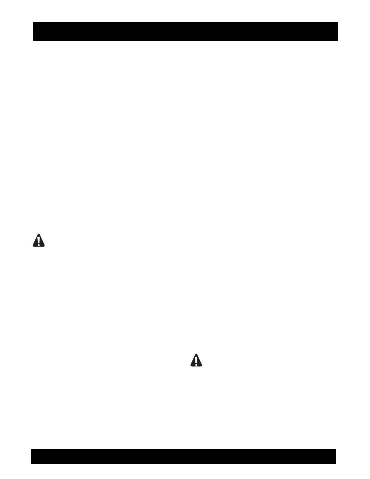
3) Surface finish and texture. The finest grained
surface finish available from the planing process is
comparable to a "swept or broomed" like finish.
FIGURE 1. If a smooth, flat finish is desired, the
planing process must be followed with a grinding or
polishing type process. Many job requirements may
call for large amounts of material to be removed, but
followed with additional specifications requiring a finer
surface finish or texture. Many times these jobs dictate
terial and remove a
and usually deliver a
ted steel flails must be
8FP FLOOR PLANER SERIES OPERATION AND PARTS MANUAL REV #2 (05/28/09) PAGE 15
Page 16
ASSEMBLY INSTRUCTIONS/OPERATIONS
the use of an aggressive flail configuration because of
productivity and cost considerations. Less aggressive
flail configurations can then be utilized for the final
finishing sequence. Generally speaking, the more
aggressive the flail configuration, the more coarse the
resulting finish and texture.
FIGURE 1
Many flail configurations are available to meet a wide
variety of job application and surface material
specifications. To give additional perspective to each
configuration a rating system of 1 to 10 (10 being
highest) has been devised.
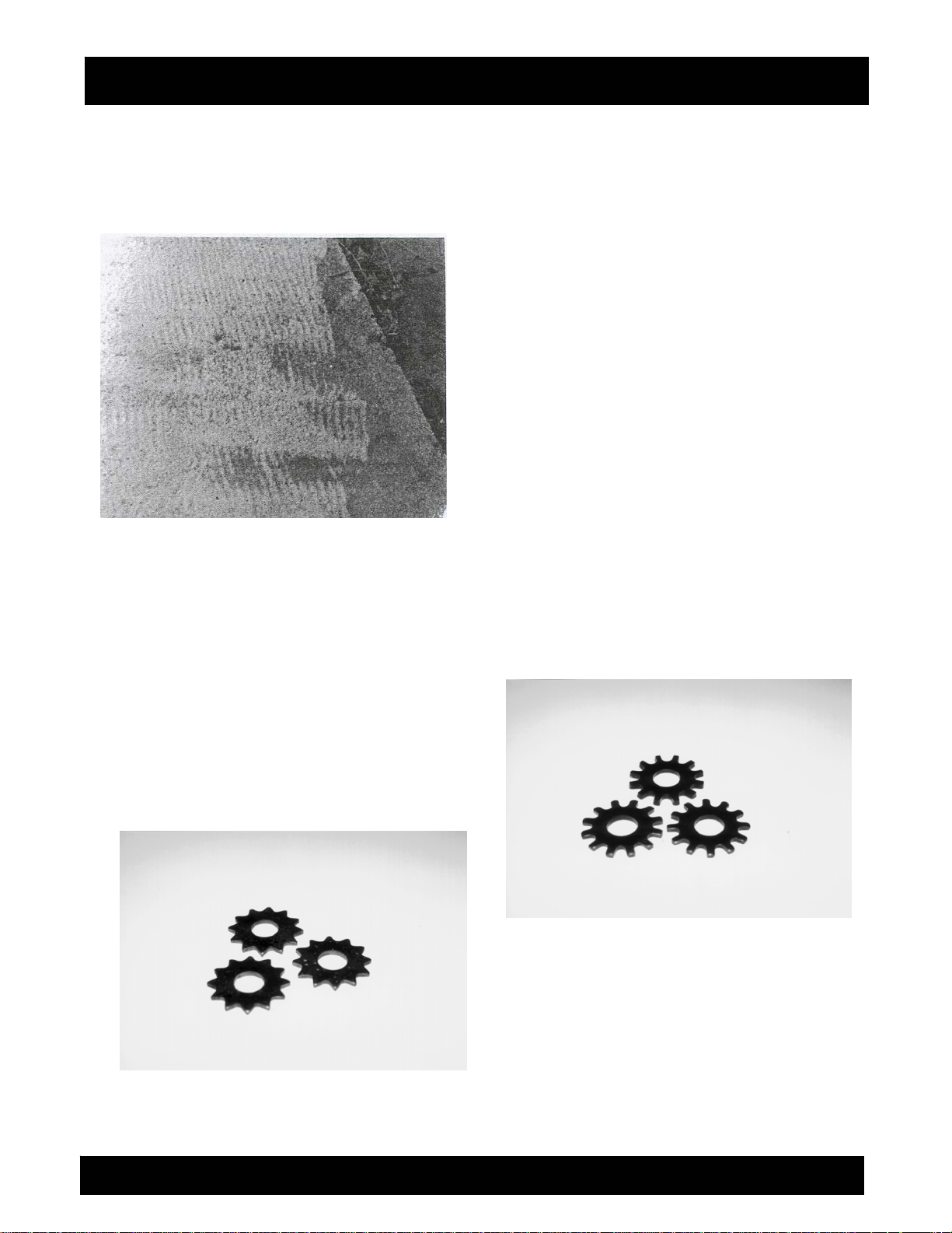
Star Flail
The star type flail is ma
alloy steel that is through hardened for additional
service life. FIGURE 2. It is highly effective for light
cleaning or scarifying and delivers a fine surface finish
texture. Designed for medium to high speed material
removal of the work surface.
FIGURE 2
nufactured from high carbon,
Suggested Applications:
1) Removal of thin coatings and encrusted
accumulations.
2) Cleaning concrete and asphaltic surfaces.
3) Removing thick material build-ups of greases,
paints, oils, vegetable powders and some resins from
wood floors.
4) Light scarifying prior to the application of coatings,
toppings or sealers.
5) Light, steel deck descaling projects.
COST 1
PRODUCTIVITY 3
SERVICE LIFE 1. The star flail should be replaced
when the outside diameter is worn to approximately 15/16 inch or the inside diameter elongates to
approximately 3/4 inch.
Beam Flail
The beam type flail is manufactured from high
carbon, alloy steel that is through hardened for
additional service life. FIGURE 3. It is highly effective
for scabbling or scarifying and delivers medium to
coarse surface finish texture. Designed for medium to
high speed material removal of the work surface.
FIGURE 3
8FP FLOOR PLANER SERIES OPERATION AND PARTS MANUAL REV #2 (05/28/09) PAGE 16
Page 17
ASSEMBLY INSTRUCTIONS/OPERATIONS
Suggested Applications:
1) Medium duty asphalt and concrete milling.
2) Descaling steel decks.
3) Removing thick material build-ups of greases,
paints, oils, vegetable powders and resins from nonwood type floors.
4) Dried, fully cured, carpet and tile adhesive removal.
5) Painted traffic line removal.
COST 1
PRODUCTIVITY 5
SERVICE LIFE 2. The beam flail should be replaced
when the outside diameter is worn to approximately 15/16 inch or the inside diameter elongates to
approximately 3/4 inch.
Pentagonal Flail
The pentagonal flail is manufactured from high
carbon, alloy steel that is through hardened for
additional service life. FIGURE 4. Each section of the
five sided design features a small, tungsten ca
insert that is first placed in a small hole and then held
in position with copper brazing. It is highly effective for
scabbling or scarifying and delivers medium to coarse
surface finish texture. Designed for high speed
material removal of the work surface.
FIGURE 4
Suggested Applications:
1) Heavy duty asphalt and concrete milling.
2) Milling concrete joints.
3) Asphalt and concrete grooving.
The pentagonal flail is designed for more aggressive
rbide
and rapid removal of a surface in comparison to the
beam flail. The addition of the tungsten carbide inserts
contributes to its long service life and higher
production rates. The tungsten carbide is also the
main reason for the cost differential between it and the
other flails. The design configur
coarse surface finish and texture. For many job
applications, this finish and texture will be satisfactory.
Some applications may require an additional
smoothing process. For example: removing high spots
or other irregularities from sidewalks. The initial
process would utilize pentagonal flails for productivity
and service life reasons. If the resulting surface finish
is too coarse to meet specifications, it can be
smoothed with the use of the star or beam flails.
COST 10
PRODUCTIVITY 8
SERVICE LIFE 10. The pentagonal flail should be
replaced when two successive tungsten carbide
inserts break off or the inside diameter elongates to
approximately 3/4 inch. In service, the flail body will
ar much faster than the tungsten carbide inserts.
we
The copper brazing used to weld the inserts into the
body can fail and an insert break off. The flail can still
be used in service. It will just wear a little faster and
more uneven in that particular area. As a general rule,
a pentagonal flail can be utilized until there has been
body wear that will no longer support the tungsten
carbide inserts.
Milling Flail
The milling flail is manufactured from high carbon,
alloy steel that is heat treated for additional service
life. FIGURE 5. Each section of the five sided design
features a rect
held in position with copper brazing. The milling flail is
primarily designed for "climb" milling applications.
This requires that the Floor Planer be pulled toward
the operator when being utilized. Removal rates are
dependent upon both surface and substrate material
composition.
FIGURE 5
angular, tungsten carbide insert that is
ation yields a rather
8FP FLOOR PLANER SERIES OPERATION AND PARTS MANUAL REV #2 (05/28/09) PAGE 17
Page 18
ASSEMBLY INSTRUCTIONS/OPERATIONS
Suggested Applications:
1) Removing synthetic coatings, thermoplastic and
cold plastic marking and lines from concrete and
asphaltic surfaces.
COST 10
PRODUCTIVITY 7
SERVICE LIFE 7. Milling flails are designed to remove
a variety of traffic line materials from concrete and
asphaltic type surfaces. With proper techniques,
minimal amounts of parent work surface material will
also be removed during the planing process. Milling
flails are expensive. To realize maximum service life,
milling flails should not be utilized for the direct
removal of concrete and asphaltic work surface
materials. Such use will drastically reduce their
service life and subst
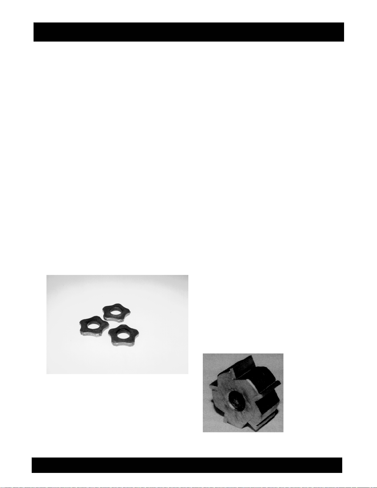
SPACER WASHERS.
Spacer washers are stamped from high carbon, alloy
steel that is heat treated for additional service life.
FIGURE 6.
FIGURE 6
The Function of Spacer Washers
1) Reduce the number of flails required to be mounted
on the flail drum, thus reducing purchase and
operational costs.
2) Arrange the flails in a sequence or pattern that
minimizes "blind" or "open" spots created by the
additional support plates of the two section flail drum.
Always insert at least one spacer washer between two
(2) consecutive flails. The exception to this rule is a
configuration where its design does not require the
use of spacer washers. A flail drum set up with only
star, bea
will not penetrate the work surface at satisfactory
rates. Typical configurations minimize the hammering
or impact action of the flails. However, this can also be
useful when removing traffic lines.
m or pentagonal flails and no spacer washers
antially increase project costs.
3) Allow the flails to be arranged on the one section
flail drum in configurations of specific widths for many
job applications. An example would be the use of
pentagonal flails to groove a concrete floor. The
spacer washers are used to position the pentagonal
flails at the desired width. FIGURE 7.
Variances in ma
processes can affect the final thickness of both flails
and spacer washers. Because of this occurrence, trial
and error is important for assembling flails and spacer
washers on a flail drum. By mixing and matching flails
and spacer washers of specific thicknesses, the
required number of components can be assembled on
a flail drum in a minimum amount of time.
DANGER
USE ONLY FACTORY SUPPLIED SPACER
WASHERS ON THE FLAIL DRUM. OTHER
WASHER TYPES AND/OR CONFIGURATIONS CAN
PRODUCE ABNORMAL WEAR AND ELONGATION,
RESULTING IN COMPLETE SEPARATION FROM
THE FLAIL DRUM. SPACER WASHER
SEPARATION CAN RESULT IN PROPERTY LOSS
AND/OR PERSONAL INJURY.
FIGURE 7
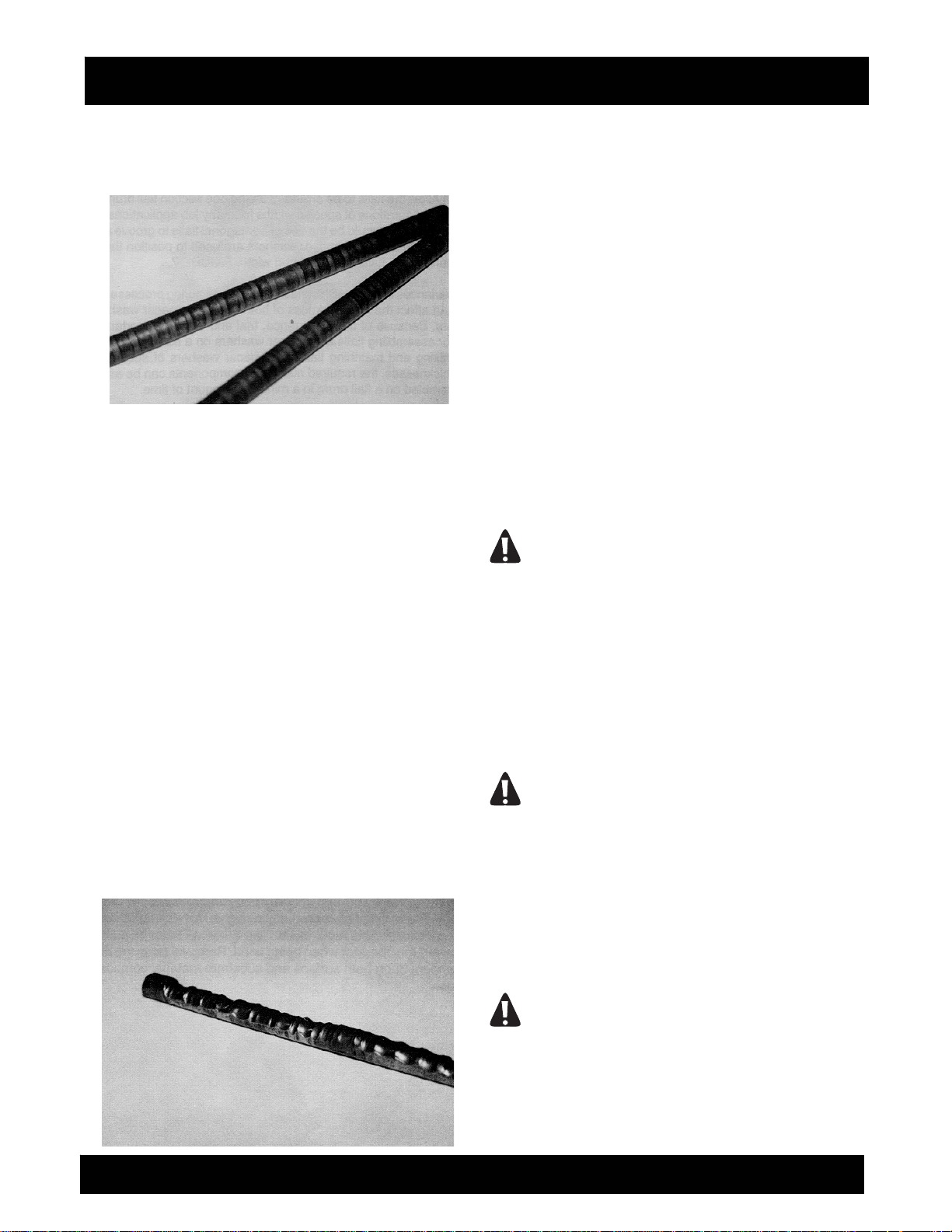
FLAIL DRUM RODS
Flail drum rods are manufactured from 1/2 inch
diameter alloy steel. They are heat treated in a two
step process that yields a surface hardness that
resists wear and extends service life.
Drum rod service life is difficult to predict because of
the large number of flail configurations and work
surface materials. Normal wear should be uniform
about the rod circumference. FIGURE 8.
terial thickness and manufacturing
8FP FLOOR PLANER SERIES OPERATION AND PARTS MANUAL REV #2 (05/28/09) PAGE 18
Page 19
ASSEMBLY INSTRUCTIONS/OPERATIONS
FIGURE 8
Problems encountered by uneven component
wear
1) Inadequate free play exists between the
flails/spacer washers and the support plates of the flail
drum. If the flails and spacer washers do not have
complete freedom of movement, they will not be
capable of properly rotating about the flail drum rod.
The result is rod wear confined to two locations that
are usually 180 degrees apart. FIGURE 9. Variances
in flail and spacer washer thicknesses affects free play
when assembled on the drum. Because free play is
also created during the planing process due to actual
flail and spacer w
"tightness" can sometimes be tolerated without
affecting the service life of the drum rods or flails. The
specific amount of "tightness" can usually be
determined through trial and error. If the flails and
spacer washers appear too tight on the drum, remove
an appropriate flail or washer and reassemble the
drum. If a short, operational test indicates normal
component wear patterns, the apparent problem has
been solved. A general rule for consideration: it is
better to have the flails and spacer washers a "little too
loose" on the drum than
asher wear, a certain amount of
a "little too tight".
FIGURE 9
2) Mixing both worn and new flails on the drum. Proper
flail action against the work surface material requires
that the flails be of the same, approximate dimensions.
Flails with various inside and outside dimensions will
not impact the work surface material with the same
intensity and deliver the same results. Flail rod wear is
directly proportional to the amount of force it must
supply against each, individual flail. When a rod can
no longer supply adequate force against the flails, it
will break, allowing the flails to be hurdled a
inside of the Floor Planer frame. The more aggressive
flails require greater forces to keep them contained on
the rod. These forces, in turn, create faster and/or
uneven rod wear rates.
Because flail drum rods are a critical component of the
actual planing process, it is important that each rod be
inspected on a regular basis to determine proper
structural integrity.
DANGER
INSPECT EACH FLAIL DRUM ROD ON A
REGULAR INTERVAL TO DETERMINE PROPER
STRUCTURAL INTEGRITY. USAGE RATES AND
OTHER OPERATING PARAMETERS WILL
DETERMINE PROPER INTERVAL RATES. IF
THERE IS ANY QUESTION REGARDING THE
VISUAL STRUCTURAL INTEGRITY OF A DRUM
ROD, PROPERLY DISCARD AND REPLACE IT
WITH AN APPROVED, FACTORY REPLACE- MENT
PART ONLY.
DANGER
THE MINIMUM ALLOWABLE DRUM ROD
DIAMETER IS 3/8 INCH AS MEASURED ALONG
ANY PART OF ITS CIRCUMFERENCE AND/OR
LENGTH. ANY DRUM ROD NOT MEETING THIS
MINIMUM DIMENSION STANDARD SHOULD BE
PROPERLY DISCARDED AND REPLACED WITH
AN APPROVED, FACTORY REPLACEMENT PART
ONLY.
DANGER
UNDER NO CIRCUMSTANCE IS WELDING AND/OR
ANY OTHER TYPE OF METAL BUILD-UP
PROCESS ALLOWED TO BE PERFORMED ON A
WORN DRUM ROD. TYPICAL MAINTENANCE
TECHNIQUES CAN ALTER THE ORIGINAL HEAT
gainst the
8FP FLOOR PLANER SERIES OPERATION AND PARTS MANUAL REV #2 (05/28/09) PAGE 19
Page 20
ASSEMBLY INSTRUCTIONS/OPERATIONS
TREATMENT PROCESS AND COMPROMISE THE
STRUCTURAL INTEGRITY, RESULTING IN
PROPERTY DAMAGE AND/OR PERSONAL
INJURY.
On occasion, it may be necessary to remove severely
worn drum rods from the flail drum by the use of a
band saw or similar device. FIGURE 10. Proper
preventative maintenance and operational procedures
will minimize these occurrences.
FIGURE 10
CAUTION
Utilize proper personal protection devices and
exercise caution when attempting this procedure.
Secure/stabilize the drum on a solid surface to
prevent accidental rotation.
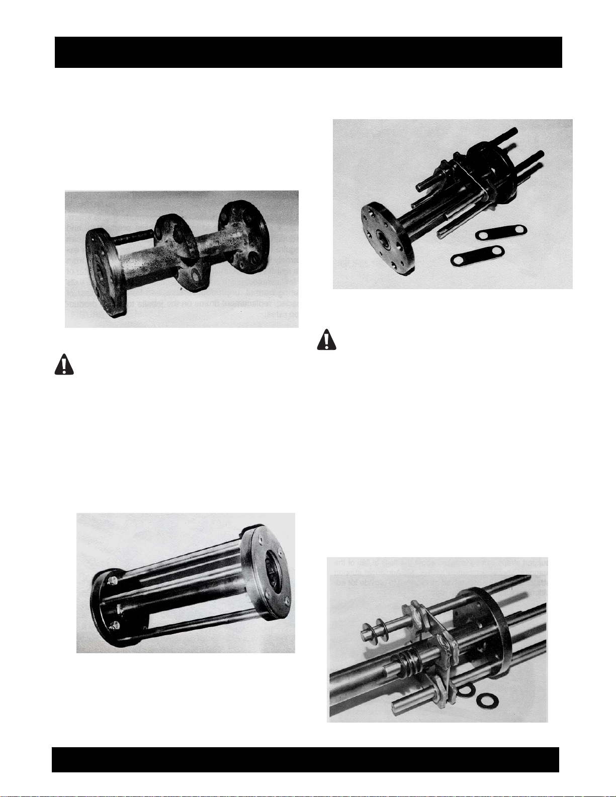
FLAIL DRUM DESIGN AND APPLICATION.
Flail drums are manufactured from alloy steel and heat
treated to extend the service life. Drums are classified
by the number of sections between the side plates.
FIGURE 11
The one section flail drum incorporates the four flail
rods supported only by the end plates. FIGURE 11.
To provide additional stability and structural rigidity for
the drum rods, four support straps are included as a
standard accessory. These support straps can be
installed about the flails in lieu of the standard spacer
washers. FIGURE 12. Additional support straps can
also be assembled as required to provide for
additional rigidity for the drum rods.
FIGURE 12
CAUTION
Never operate the one section drum without the
use of a proper quantity of support straps to
provide for additional stability and structural
integrity. Property damage and/or personal injury
can result.
The added flexibility of the one section flail drum can
be especially useful on many, specialized job
applications. These job applications are usually limited
to grooving, or light scabbling and scarifying
applications. Example: grooving concrete floors to
minimize the chance of animals and humans from
falling and sustaining injuries. This end result can be
readily accomplished by the correct spacing of flails,
spacer washers and support straps on a one section
drum. FIGURE 13.
8FP FLOOR PLANER SERIES OPERATION AND PARTS MANUAL REV #2 (05/28/09) PAGE 20
Page 21

ASSEMBLY INSTRUCTIONS/OPERATIONS
FIGURE 13
The most widely used drum is of the two-section
design. FIGURE 14. It incorporates two half sectioned
side plates that are positioned on the center shaft to
facilitate optimum flail spacing. The half side plate
sections also provide additional stability and structural
rigidity for the drum rods. The two-section drum can
accommodate the use of all flail designs while meeting
the most demanding job applications.
General Notes Regarding Flail Drums
1) Flail drum rods are held in position by end caps and
related fasteners. The end caps are heat treated to
extend their service life.
2) The countersunk Allen head capscrews are
retained to the flail drum by both self locking, hexa
head nuts and lock washers. The lock washers
provide additional redundancy while eliminating open,
FIGURE 14
exposed threads that can become worn or damaged
from field use. A countersunk Allen head capscrew
was chosen over a conventional hexagon head
capscrew to eliminate anticipated wear. Component
wear would substantially increase the difficulty of
disassembling drum components in the field. Before
removing these capscrews, clean the internal hexagon
with an appropriate tool to help facilitate their removal.
3) Flail rods are not intended to rotate in the drum
assembly while the Floor Pla
Severe operation can cause the drum plates to wear
and elongate. Drum rods are also subject to wear and
elongation. If the total amount of wear is not severe,
various types of high strength, anaerobic adhesives
can be utilized to secure the rods to the drum. Severe
component wear is always an immediate reason to
reject either the rods and/or drum and replace with
factory approved, replacement parts.
ner is in operation.
gon
4) Regularly inspect the drum for excessive wear and
signs of fatigue. Random vibration caused by the
planing process is difficult, if not impossible, to fully
predict. Component service life is impossible to
predict. Work surface materi
and general maintenance are also contributing factors
that will limit the service life of the drum and/or
components. If there is any question regarding the
structural integrity of a drum or any component,
properly discard and replace with factory approved,
replacement parts.
5) It is advisable to always have a minimum of one
spare, loaded drum available to increase job site
productivity and reduce down time. Replacing worn
flails is a job that can require from only a few, short
minutes to even hours for extremely worn and
damaged components. Repl
driveshaft can usually be accomplished in a matter of
a few minutes. It is a common practice to replace worn
flails during normal, unproductive time and keep a
number of loaded, replacement drums on the job site
to speed production rates.
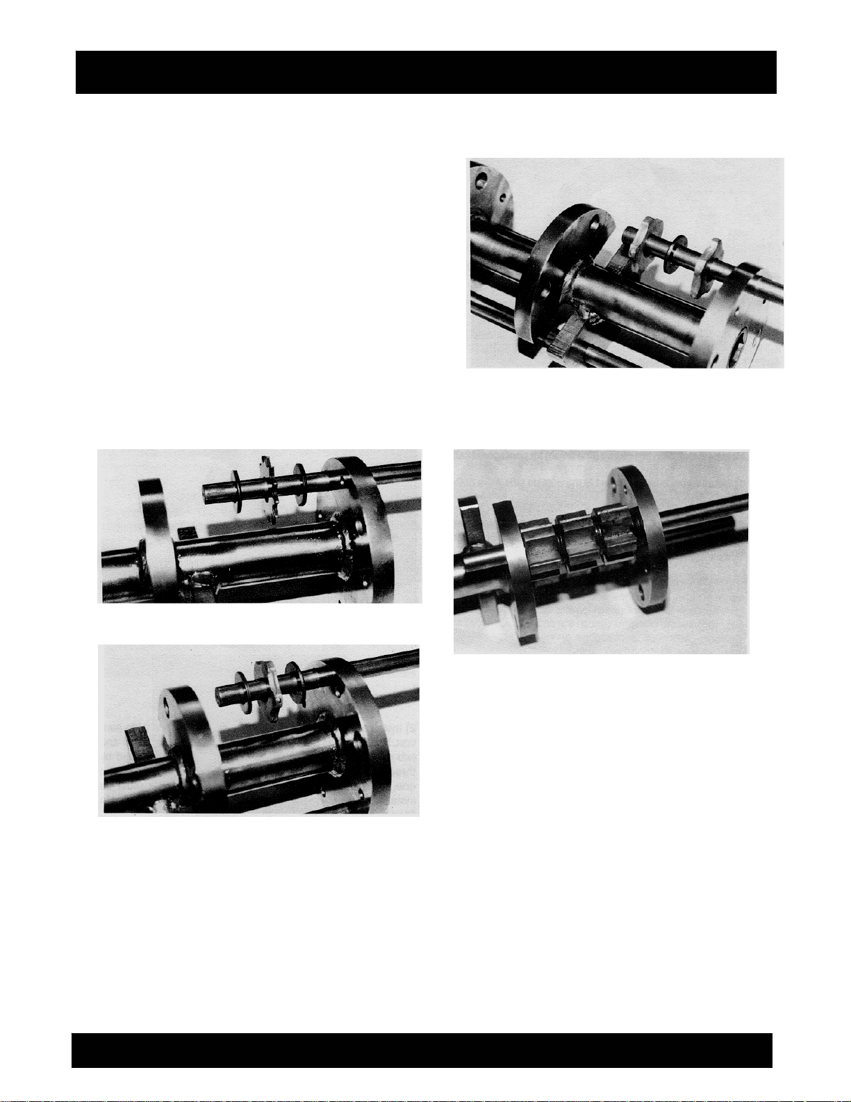
INSTALLING FLAILS ON THE TWO SECTION
DRUM.
All flails are assembled on the two section drum in
sequence patterns with the spacer washers. Spacer
washers provide for an overlapping effect of the flails
that produces consistent material removal from the
work surface.
Normal installation procedure (fine finish) for star,
beam and all 1/8-inch nominal thickness flails
1) Install a flail next to the outside side plate of the
narrow section. Next, install a spa
with a flail and continue the sequence until the section
is full. FIGURE 15.
FIGURE 15
als, operator techniques
acing a drum on the
cer washer. Follow
8FP FLOOR PLANER SERIES OPERATION AND PARTS MANUAL REV #2 (05/28/09) PAGE 21
Page 22
ASSEMBLY INSTRUCTIONS/OPERATIONS
2) Install a spacer washer next to the outside side
plate of the wide section. Next, install a flail. Follow
with a spacer washer and continue the sequence until
the section is full. FIGURE 16.
Normal installation procedure (fine finish) for
pentagonal flails
1) Install a spacer washer next to the outside side
plate of the narrow section. Next, install a flail. Follow
with a spacer washer and continue the sequence until
the section is full. FIGURE 17.
2) Install a flail next to the outside side plate of the
wide section. Next, install a spacer washer. Follow
with a flail and continue the sequence until the section
is full. FIGURE 18.
FIGURE 16
FIGURE 17
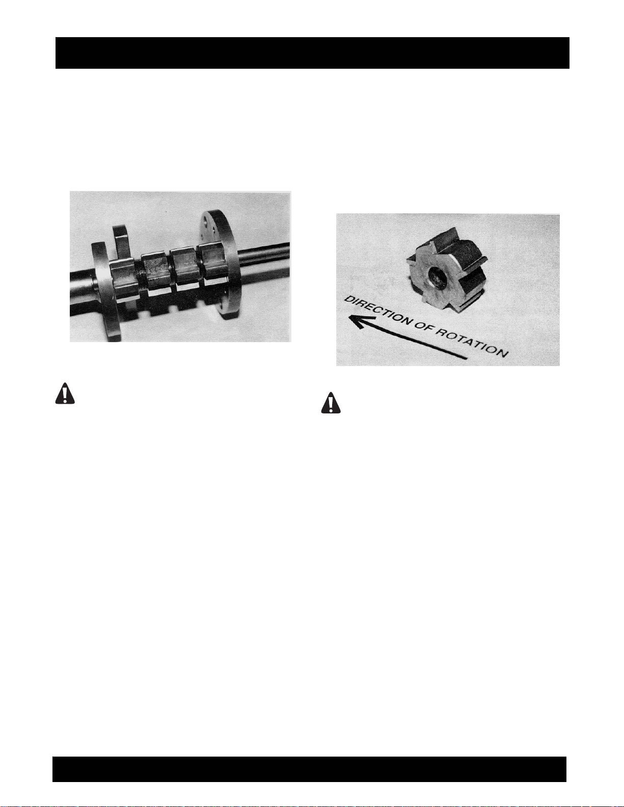
Normal installation procedure for milling flails
1) Install three spacer washers next to the outside side
plate of the narrow section. Next, install a
with two spacer washers and continue the sequence
until the section is full. The tungsten carbide inserts
must be installed to form a continuous planing surface.
FIGURE 19.
flail. Follow
FIGURE 18
FIGURE 19
2) Install a flail next to the outside side plate of the
wide section. Next, install two spacer washers. Follow
with a flail and two spacer washers. Install another
milling flail followed by three spacer washers. Finally,
install the remaining flail and one spacer washer. The
tungsten carbide inserts must be installed to form the
same, continuous planing surface as in Step 1.
FIGURE 20.
3) Milling flails can also be installed on the drum
without the use of sp
acer washers.
8FP FLOOR PLANER SERIES OPERATION AND PARTS MANUAL REV #2 (05/28/09) PAGE 22
Page 23
ASSEMBLY INSTRUCTIONS/OPERATIONS
General Notes Regarding the Installation of Flails
1) Because of variance in material thickness and
manufacturing tolerances, the specified number of
spacer washers may not always fit within the narrow
and wide sections. If this occurs, grinding a spacer
washer to reduce its thickness is an option.
FIGURE 20
CAUTION
Exercise caution when grinding a spacer washer
to reduce its thickness. Wear safety eye wear and
other, appropriate safety apparel to minimize the
potential for personal injury.
2) Flails require sufficient free play to allow them to
properly impact the work surface material. If the flails
fit too tight on the drum, inconsistent material removal
and accelerated flail wear will result. The formation of
rust between the flail and spacer washer surfaces will
affect proper free play. Excessive free play can also
accelerate the wear of flails and rods. As a general
rule, flails should be free to rotate by hand after being
installed on the drum. If this is not possible, the flails
should be disassembled and additional free play
provided by reducing the thickness of a
washer.
3) All flails are bi-directional in design with the
exception of the milling flail. That is, there is no
forward or reverse orientation on the drum. Fail
service life can sometimes be extended by reversing
their orientation on the driveshaft. The effect is similar
to rotating tires on an automobile.
4) As the name implies, the tungsten carbide inserts of
the milling flail cut the work surface material with an
action very similar to that of a machine tool cutting
spacer
steel. The brittleness of the tungsten carbide insert
requires that it be fully supported to minimize
breakage. This requires a substantial flail body to
provide the necessary support. The resulting
configuration makes the milling flail one directional in
design. This limita
loaded drum on the driveshaft with the tungsten
carbide inserts facing the direction of rotation. FIGURE
21. If the tungsten carbide inserts face opposite to the
direction of rotation, improper milling action and
accelerated flail wear will occur.
FIGURE 21
CAUTION
Before installing the drum on the driveshaft, make
a close, visual inspection of the entire assembly.
Determine that all flails and spacer washers are
properly secured on the rods and that no loose
flail or spacer washer has slipped its position
during assembly. Flails and spacer washers can
fall off the rods during assembly and become
dislodged and unnoticed. When the loaded drum
begins rotating at high speeds, these components
can fly off the drum causing property damage
and/or personal injury.
INSTALLING A LOADED DRUM ON THE
DRIVESHAFT.
Application: All Models.
Tools required:
1 each, 3/4 inch wrench or equivalent.
1 each, torque wrench, 85 ft lbs (115 N.m) capacity
with 3/4 inch socket.
1) If the Floor Planer is powered by an engine,
disconnect the spark plug wire. If powered by an
electric motor, properly disconnect the extension cord
of Floor Planer from the power source.
2) Rotate the height adjustment lever located on the
tion requires the operator to install a
8FP FLOOR PLANER SERIES OPERATION AND PARTS MANUAL REV #2 (05/28/09) PAGE 23
Page 24

ASSEMBLY INSTRUCTIONS/OPERATIONS
operator handle counterclockwise to raise the Floor
Planer to its maximum height position above the work
surface.
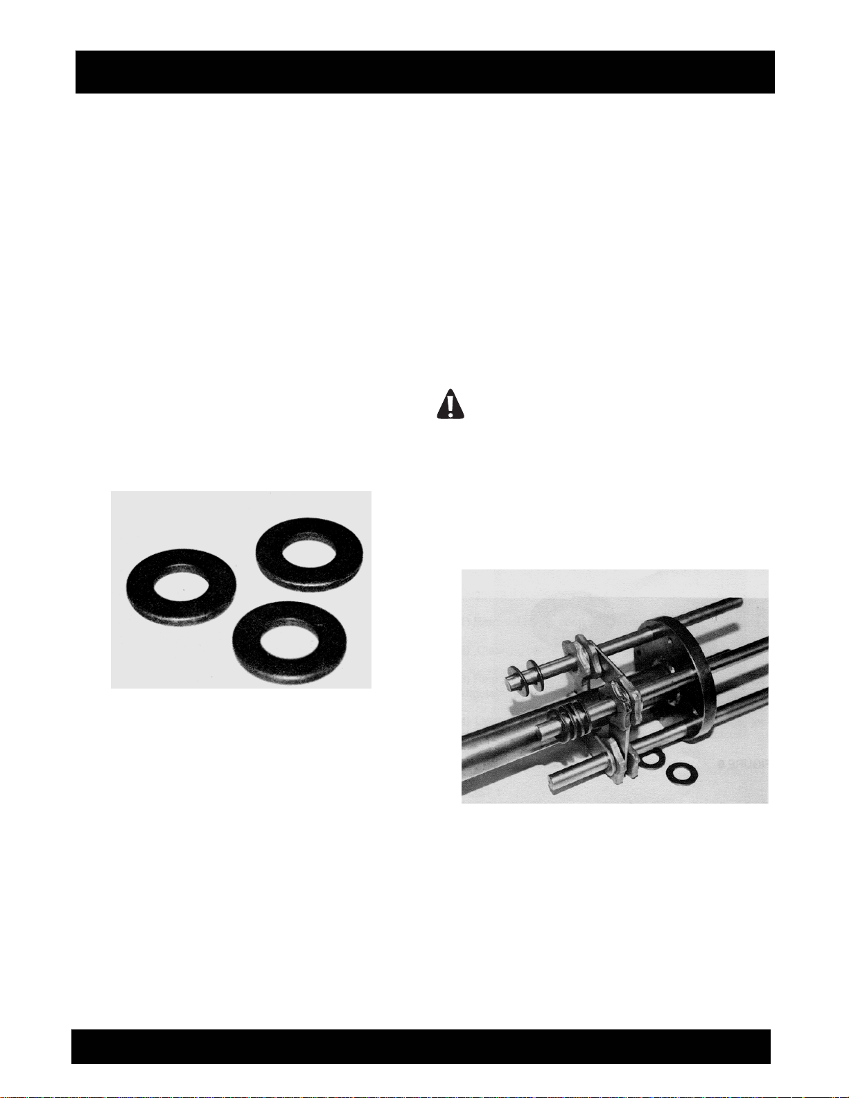
3) Using the wrench, remove the four (4) 1/2-inch
diameter x 1 inch long capscrews and flat washers
securing the drum access plate to the main frame.
4) Remove the drum access plate from the driveshaft.
5) Clean and remove any excessive material build-up
from the threaded bosses and surrounding areas.
6) Install the loaded flail drum on the driveshaft. If
utilizing the milling flails or other flail configurations
that are unidirectional, determine that the flails are
facing the direction of rotation. FIGURE 22.
7) Install the drum
left, vertical side of the access plate should align tight
against the main frame.
8) Install the four 1/2-inch diameter x 1 inch long cap-
screws and wa shers. capscrews should install with a
minimal amount of resistance and related, alignment
problems. Torque the capscrews to 85 ft lbs (115
N.m). No lockwashers or similar devices are required.
9) If the Floor Planer is powered by an engine,
reconnect the engine spark plug wire. If powered by
an electric motor and the machine is to be used
immediately, reconnect the extension cord of Floor
Planer to the power source. Determine that the
ON/OFF switch located on the operator handle is in
the OFF position.
DANGER
UNEXPECTED MACHINE START UP CAN RESULT
IN PROPERTY DAMAGE AND/OR PERSONAL
INJURY.
10) Removing a loaded drum from the driveshaft is
accomplished by reversing the above steps.
access plate on the driveshaft. The
FIGURE 22
TRANSPORTING THE FLOOR PLANER.
Application: All Models.
The Floor Planer has an operational weight that
prohibits one person from loading and/or unloading it
alone by conventional, physical efforts.
DANGER
DO NOT ATTEMPT TO LIFT THE FLOOR PLANER
UP INTO A TRANSPORTATION VEHICLE WITH
THE USE OF ONE PERSON ALONE. DO NOT
ATTEMPT TO LOWER THE FLOOR PLANER FROM
A TRANSPORTATION VEHICLE WITH THE USE OF
ONE PERSON ALONE. LIFT AND/OR LOWER THE
FLOOR PLANER ONLY BY THE USE OF A POWER
TAILGATE UNIT, A SUITABLE HOIST UNIT OF
PROPER CAPACITY AND/OR CONFIGURATION
OR BY THE USE OF A PROPER QUANTITY OF
PERSONNEL IN PROPER PHYSICAL CONDITION.
1) A lifting bail device can be used to facilitate lifting by
8FP FLOOR PLANER SERIES OPERATION AND PARTS MANUAL REV #2 (05/28/09) PAGE 24
Page 25

ASSEMBLY INSTRUCTIONS/OPERATIONS
a mechanical device incorporating a chain and
suitable attachment device. The location of the lifting
bail may not always locate the exact position of the
center of gravity for the Floor Planer. A lifting handle is
provided on the front of the main frame. This handle
can be utilized by personnel whenever lifting/lowering
the Floor Planer.
DANGER
EXERCISE EXTREME CAUTION WHEN UTILIZING
A MECHANICAL DEVICE FOR LIFTING THE
FLOOR PLANER. UTILIZE THE MECHANICAL
DEVICE IN ACCORDANCE TO BOTH ITS STATED
STATIC AND DYNAMIC LOADING ENVELOPES.
DO NOT UTILIZE THE MECHANICAL DEVICE
UNTIL THIS INFORMATION IS PROPERLY KNOWN
AND UNDERSTOOD BY ALL APPLICABLE
PERSONNEL. FAILURE TO PROPERLY UTILIZE
THE MECHANICAL DEVICE CAN RESULT IN
PROPERTY DAMAGE AND/OR PERSONAL
INJURY.
When transporting the Floor Planer on a motor
vehicle, the fuel tank breather vent (if so equipped)
must be completely closed to eliminate the accidental
seepage of fuel and resulting potential fire and
environmental hazards. In order to minimize the
possibility of damage to the Floor Planer, always
transport in its normal, upright position. All equipment
must be secured in/on vehicles with suitable strapping
or tie-downs. Personnel should not be transported in
the same compartment as equipment and fuel
supplies. Consult applicable OSHA, AGA, CGA, etc.
regulations for the proper transportation of gasoline
and other, flammable gases.
STARTING THE 8FP/E SERIES ELECTRICALLY
POWERED FLOOR PLANER ON THE JOBSITE.
1) Position the Floor Planer on a flat
of firm foundation.
2) Determine that the ON/OFF switch located on the
operator handle is in the OFF position.
3) Rotate the height adjustment lever located on the
operator handle counterclockwise to raise the Floor
Planer to its maximum height position above the work
surface.
and level surface
DANGER
DO NOT ATTEMPT TO START THE MOTOR
WITHOUT FIRST DETERMINING THAT THE
LOADED DRUM IS NOT IN CONTACT WITH THE
WORK SURFACE. IF THE ROTATING FLAILS
COME IN CONTACT WITHE THE WORK SURFACE
BEFORE THE OPERATOR HAS ASSUMED FULL
CONTROL, THE ACTION HAS THE POTENTIAL TO
PULL THE FLOOR PLANER AWAY. A RUNAWAY
FLOOR PLANER CAN CAUSE PROPERTY
DAMAGE AND/OR PERSONAL INJURY.
4) The electric motor req a clean, 10 ampere, 230
VAC, 60 Hz nominal power source. A clean power
source refers to the amperage available on the
individual electrical circuit selected. Additional
electrical products already utilizing the same circuit will
reduce the available amperage, resulting in starting
and operational difficulties.
CAUTION
Operating the Floor Planer from a power source of
improper voltage and amperage will result in
unrepairable damage to the electric motor and
related controls.
5) Providing proper voltage and amperage levels to
the electric motor is essential to obtain maximum
productivity and service life. Low voltage and
amperage levels will cause the motor to overheat. The
motor is equipped with an automatic thermal
protection device that will stop it before major internal
damage can result. After the motor has cooled to an
acceptable temperature level, the switch must be
manually activated to restart. FIGURE 24.
FIGURE 24
8FP FLOOR PLANER SERIES OPERATION AND PARTS MANUAL REV #2 (05/28/09) PAGE 25
Page 26

ASSEMBLY INSTRUCTIONS/OPERATIONS
To minimize the voltage drop to the motor, all
extension cords should be copper stranded, 8 AWG or
larger. A NEMA 6-20R twist lock type receptacle is
provided with the 8FP/E Series Floor Planer as a
standard accessory. The twist lock feature allows the
extension cord to be pulled by the Floor Planer without
becoming detached. Wire the NEMA 6-20R receptacle
to the appropriate extension cord that will be coupled
to the NEMA 6-20P plug provided on the Floor Planer.
FIGURE 25.
DANGER
PROPERLY INSPECT ALL EXTENSION CORDS
AND WIRING DEVICES FOR STRUCTURAL
INTEGRITY. DO NOT UTILIZE A CORD WITH A
WORN OR CUT OUTER JACKET MATERIAL. DO
NOT UTILIZE A CORD WITH EXPOSED INNER
WIRES OR INSULATION MATERIAL. DO NOT
UTILIZE A CORD THAT HAS BEEN REPAIRED
WITH ELECTRICAL TAPE. USE OF AN EXTENSION
CORD OF IMPROPER STRUCTURAL INTEGRITY
CAN RESULT IN PROPERTY DAMAGE AND/OR
PERSONAL INJURY.
any questions regarding the suitability of a specific
power outlet, contact the Customer Service
Department for assistance BEFORE utilizing the Floor
Planer. There is no charge for this service. A qualified
electrician can also be consulted. If a 115 VAC power
source is selected, it is recommended that a properly
tested, externally mounted, ground fault circuit
interrupter (GFCI) be utilized at all times as an
additional precaution. Ground fault circuit interrupters
are not available for operation on 230 VAC. FIGURE
26.
FIGURE 26
DANGER
ALL ELECTRICAL WIRING MUST BE INSTALLED
AND/OR APPROVED IN ACCORDANCE TO LOCAL
ELECTRICAL CODES AND PRACTICES. AN
IMPROPER WIRING INSTALLATION CAN RESULT
IN PROPERTY DAMAGE AND/OR PERSONAL
INJURY.
FIGURE 25
6) Determine that the power outlet to be utilized is
properly grounded. This can be accomplished with
proper testing equipment and procedures. If there are
DANGER
FOR MAXIMUM PROTECTION AGAINST A FAULT,
ALWAYS CONFIGURE THE GROUND FAULT
CIRCUIT INTERRUPTER TO BE PLUGGED INTO
THE EXTENSION CORD. A CONFIGURATION
WITH THE GROUND FAULT CIRCUIT
INTERRUPTER PLACED BETWEEN THE POWER
SOURCE AND THE EXTENSION CORD WILL NOT
AFFORD MAXIMUM PROTECTION AGAINST A
POTENTIAL FAULT.
7) Couple the NEMA 6-20R receptacle and the NEMA
6-20P plug together.
8) Grasp the operator handle with firm gripping. Turn
the ON/OFF switch to the ON position.
When operating on 115 VAC, the electric motor will
require additional starting time to help compensate for
the additional starting amperage requirement. This
time is usually within two seconds of activating the
ON/OFF switch.
9) The 8FP/E Series electrically powered Floor Planer
is not equipped with a centrifugal clutch assembly. The
electric motor is directly coupled to the driveshaft by a
V-belt reduction.
8FP FLOOR PLANER SERIES OPERATION AND PARTS MANUAL REV #2 (05/28/09) PAGE 26
Page 27

ASSEMBLY INSTRUCTIONS/OPERATIONS
DANGER
AS SOON AS THE ELECTRIC MOTOR HAS
STARTED, THE OPERATOR MUST BE IN A
POSITION TO ASSUME DIRECT AND FULL
CONTROL OF THE FLOOR PLANER. FAILURE TO
ASSUME DIRECT AND FULL CONTROL CAN
RESULT IN PROPERTY DAMAGE AND/OR
PERSONAL INJURY.
10) The 8FP/E Series electrically powered Floor
Planer is stopped by moving the ON/OFF switch
located on the operator handle to the OFF position.
For safety considerations, it is recommended that the
extension cord be disconnected from both the Floor
Planer and electric power source whenever the Floor
Planer is not in use on the jobsite.
STARTING THE 8FP/G SERIES GASOLINE
POWERED FLOOR PLANER ON THE JOBSITE.
1) Position the Floor Planer on a flat and level surface
of firm foundation.
2) Rotate the height adjustment lever
counterclockwise to raise the Floor Planer to its
maximum position above the work surface. This will
insure proper clearance between the loaded drum and
the work surface.
DANGER
DO NOT ATTEMPT TO START THE ENGINE
WITHOUT FIRST DETERMINING THAT THE
LOADED DRUM IS NOT IN CONTACT WITH THE
WORK SURFACE. IF THE ROTATING FLAILS
COME IN CONTACT WITH THE WORK SURFACE
BEFORE THE OPERATOR HAS ASSUMED FULL
CONTROL, THE ACTION HAS THE POTENTIAL TO
PULL THE FLOOR PLANER AWAY. A RUNAWAY
FLOOR PLANER CAN CAUSE PROPERTY
DAMAGE AND/OR PERSONAL INJURY.
3) Refer to the material supplied by the engine
manufacturer for the correct starting, operation and
stopping procedures.
4) Allow the engine to properly "warm up" and operate
without the requirement for choking. Check for
excessive machine noise and/or vibration.
DANGER
DO NOT OPERATE A GASOLINE ENGINE IN
CLOSED SPACES WITHOUT PROPER
VENTILATION. GASOLINE ENGINES PRODUCE
CARBON MONOXIDE FUMES. BREATHING
CARBON MONOXIDE FUMES CAN RESULT IN
PROPERTY DAMAGE AND/OR PERSONAL
INJURY. EXCESSIVE LEVELS OF CARBON
MONOXIDE CAN CAUSE DEATH.
5) Stop the engine in accordance with the instructions
as described in the material supplied by the engine
manufacturer.
CAUTION
If the Floor Planer and/or an individual
component/accessory does not appear to be
functioning properly, STOP and do not further
operate the Floor Planer until the proper corrective
action has been completed. If there are any
questions regarding the proper operation of the
Floor Planer, contact the Customer Service
Department BEFORE further utilization. There is
no charge for this service.
OPERATING THE FLOOR PLANER ON THE JOB
SITE.
Application: All Models.
DANGER
THE PLANING PROCESS PRODUCES EXCESSIVE
NOISE, VIBRATION AND FLYING DEBRIS. ALL
OPERATORS AND WORK PERSONNEL IN THE
VICINITY OF THE FLOOR PLANER MUST WEAR
APPROPRIATE SAFETY EYE WEAR AND
HEARING PROTECTION DEVICES. OTHER
SAFETY APPAREL AND/OR PROCEDURES,
DEEMED NECESSARY BY SUPERVISORY
PERSONNEL MUST ALSO BE WORN AND/OR
PRACTICED BY ALL APPROPRIATE PERSONNEL.
DANGER
EXERCISE EXTREME CAUTION WHEN
OPERATING THE FLOOR PLANER IN THE
VICINITY OF DECK INSERTS, PIPES, COLUMNS,
OPENINGS, LARGE CRACKS, UTILITY OUTLETS
OR ANY OBJECT PROTRUDING FROM THE
SURFACE. CONTACT WITH SUCH OBJECTS CAN
LEAD TO LOSS OF MACHINE CONTROL,
RESULTING IN PROPERTY DAMAGE AND/OR
PERSONAL INJURY.
8FP FLOOR PLANER SERIES OPERATION AND PARTS MANUAL REV #2 (05/28/09) PAGE 27
Page 28

ASSEMBLY INSTRUCTIONS/OPERATIONS
DANGER
DO NOT OPERATE A GASOLINE ENGINE IN
CLOSED SPACES WITHOUT PROPER
VENTILATION. GASOLINE ENGINES PRODUCE
CARBON MONOXIDE FUMES. BREATHING
CARBON MONOXIDE FUMES CAN RESULT IN
PROPERTY DAMAGE AND/OR PERSONAL
INJURY. EXCESSIVE LEVELS OF CARBON
MONOXIDE CAN CAUSE DEATH.
1) Flail cutting depth is controlled by the height
adjustment lever . Rotate the lever counterclockwise to
raise the flail drum off the work surface. Rotate the
lever clockwise to lower the flail drum to the work
surface. The height adjustment lever can be locked in
position by dropping the connecting capscrew head
through one of the two holes provided. FIGURE 27.
FIGURE 27
2) Proper operator position will enhance operational
safety and overall productivity. FIGURE 28. Operate
the engine at maximum, governed speed. Consult the
material supplied by the engine manufacturer and the
SPECIFICATIONS section for specific information.
3) The wide variety of potential work surface materials
along with the corresponding variety of job site
environments, makes it impossible to develop a
standardized operating procedure for the Floor Planer.
Use of the Floor Pl
error testing until satisfactory results are achieved.
Experience gained over time and common sense will
help to minimize the amount of necessary testing.
Many factors will directly affect the operating
parameters and/or techniques utilized for a specialized
job application. Some of these factors include:
aner will require constant trial and
FIGURE 28
a) Work surface material yield and tensile value. As a
general rule, these values will determine the cutting
depth achieved in one pass. Materials with high yield
and tensile values will characteristically resist/limit flail
penetration. For such materi
procedure is to make a number of shallow passes
over the work surface rather than attempt to make a
single, deep pass. The net effect is to actually
increase productivity: more material removed in less
time. Other added benefits to this technique are
decreased vibration, less operator fatigue and
increased flail service life.
b) Higher material removal rates can sometimes be
achieved by making a series of shallow passes 90
degrees to each other to form a waffle like pattern.
This technique is especially useful when planing
misaligned sidewalks
c) Job specifications may require a wide variety of
work surface finishes and textures. The smoothest
surface texture available from the Floor Planer is very
similar to a "broom" type finish. If a smoother finish
and texture is required to meet specifications, a
grinding finish must be specified. This process utilizes
and joints.
als, the accepted
8FP FLOOR PLANER SERIES OPERATION AND PARTS MANUAL REV #2 (05/28/09) PAGE 28
Page 29

ASSEMBLY INSTRUCTIONS/OPERATIONS
a different process and can not be achieved with the
Floor Planer.
4) The The Floor Planer features a "down feed" type
design for the flail drum. The flail drum rotates forward
and towards the front of the machine before the flails
impact the work surface and remove material. The
rotational direction of the drum produces a "selfpropelled" effect that assists the operator when
pushing the machine forward. Conversely, when the
operator pulls the machine back towards himself, he
must exert an additional force to overcome the "selfpropelling" force.
ALWAYS MAINTAIN PROPER CONTROL OF THE
FLOOR PLANER. IF AN OPERATOR LOOSES
CONTROL OF THE MACHINE, A "RUNAWAY"
FLOOR PLANER CAN RESULT IN PROPERTY
DAMAGE AND/OR PERSONAL INJURY. BECAUSE
OF THE UNIQUE OPERATING CHARACTERISTICS
OF THE FLOOR PLANER, THERE IS NO
PROVISION FOR THE ELECTRIC MOTOR/ENGINE
TO AUTOMATICALLY STOP IF THE OPERATOR
FAILS TO MAINTAIN PROPER CONTROL.
DANGER
WHEN OPERATING THE FLOOR PLANER ON
ABOVE GROUND LEVELS, EXERCISE EXTREME
CAUTION TO PREVENT LOSS OF CONTROL
THAT COULD ALLOW THE MACHINE AND/OR
OPERATOR TO FALL DOWN TO LOWER LEVELS.
SUCH AN OCCURRENCE CAN RESULT IN
PROPERTY DAMAGE AND/OR PERSONAL
INJURY.
5) Star, beam a nd pentagonal flail are bi-directional in
design and can be operated in both forward and
reverse directions. Milling flails are one directional in
design. This limitation requires the operator to install a
loaded drum on the driveshaft with the tungsten
carbide inserts facing the direction of rotation. FIGURE
29. Remove work surface material only by pulling the
Floor Planer towards the operator after the drum has
been lowered to the desired cutting depth. Never push
the Floor Planer forward when the milling flails are in
contact with the work surface material.
This technique will allow the following to occur:
a) The milling flail "ha
material, producing ineffective results and substantial
lower productivity.
b) Flail body material is subject to accelerated wear,
especially in the area supporting the tungsten carbide
insert. As this area wears, the insert becomes chipped
mmers" rather then "cuts" the
and can "break off" from from the flail body, thus
significantly reducing its efficiency and useful service
life.
FIGURE 29
6) The maximum cutting depth on a slab surface is 5/8
inch. It is not recommended that the Floor Planer be
utilized to achieve depths greater than this value.
7) The planing process on many work surface
materials can produce sparks, dust and other foreign
particle conta
SPARKS PRODUCED BY THE ACTIONS OF THE
FLAILS IMPACTING AGAINST THE WORK
SURFACE (FOR EXAMPLE: STRIKING ANCHOR
BOLTS) DURING THE PLANING PROCESS MAY
COME IN CONTACT WITH MATERIALS THAT CAN
RESULT IN A FIRE AND/OR EXPLOSION. THIS
OCCURRENCE CAN RESULT IN PROPERTY
DAMAGE AND/OR PERSONAL INJURY.
THE CREATION OF DUST AND OTHER FOREIGN
PARTICLE CONTAMINATION FROM THE
OPERATIONAL PROCESS CAN RESULT IN
PROPERTY DAMAGE AND/OR PERSONAL
INJURY. FOR SUCH OPERATING CONDITIONS,
ALWAYS WEAR A NIOSH/MSHA APPROVED
DUST/MIST RESPIRATOR. CONSULT
APPLICABLE OSHA REGULATIONS FOR
SPECIFIC INFORMATION.
mination.
DANGER
DANGER
8FP FLOOR PLANER SERIES OPERATION AND PARTS MANUAL REV #2 (05/28/09) PAGE 29
Page 30

ASSEMBLY INSTRUCTIONS/OPERATIONS
Dust and other particle contamination can be
controlled by the following methods:
a) The Floor Planer is equipped with a 1-1/2 or 3 inch
outside diameter vacuum tube adaptor. The 1-1/2 inch
diameter adaptor is located at the rear of the machine.
The 3 inch diameter adaptor is located at the front of
the machine. An industrial type vacuum cleaner can
be attached to the Floor Planer to remove/control dust
and other particle contamination from the work
surface. A dipstick is provided for the 1-1/2 inch
adaptor to prevent dust from exiting onto the operators
shoes and pants when a vacuum is not attached. A
astic cover is provided for the 3 inch diameter
pl
adaptor. Remove the dipstick by pulling straight back
toward the rear wheels. Insert a vacuum hose over the
tube. A hose clamp is sometimes required to properly
secure the vacuum hose to the tube. FIGURE 30.
FIGURE 30
DANGER
ALWAYS UTILIZE A VACUUM SYSTEM DESIGNED
TO OPERATE WITHIN THE SPECIFIC JOBSITE
REQUIREMENT. DUST MATERIAL CAN MEET
CLASS II OR CLASS III SPECIFICATIONS OF THE
NATIONAL ELECTRICAL CODE® FOR
HAZARDOUS LOCATION CLASSIFICATIONS.
CONSIDERATION MUST ALSO BE GIVEN TO THE
CREATION OF HAZARDOUS TYPE MATERIALS
REQUIRING SPECIFIC DISPOSAL PROCEDURES.
DETERMINE THAT THE VACUUM SYSTEM IS
PROPERLY DESIGNED TO OPERATE WITHIN
THESE ATMOSPHERES. CONSULT CURRENT
NATIONAL ELECTRIC CODE®, OSHA AND
ENVIRONMENTAL PROTECTION AGENCY
REGULATIONS FOR SPECIFIC INFORMATION.
b) The 8FG Series Floor Planers can be equipped with
a 1/4 inch NPT water mist dust control fitting (option)
on the main frame. This fitting is provided to allow the
installation of a valve and standard garden hose.
Water can be regulated by the valve to minimize dust
problems when a vacuum is not available or its use
not desired. As a general rule, a small volume of water
is required. It is not necessary to flood the work
surface material. An added benefit is that the water
can reduce the amount of heat generated by the
planing process a
bearing service life. FIGURE 31.
FIGURE 31
WATER USED IN THIS PROCEDURE CAN ACT AS
A CONDUCTOR OF ELECTRICITY. USE OF ALL
ELECTRICALLY POWERED EQUIPMENT BEING
OPERATED ON AND/OR AROUND THE VICINITY
OF THE WET WORK SURFACE INCREASES THE
POTENTIAL FOR ELECTROCUTION. CONSULT
CURRENT NATIONAL ELECTRICAL CODES AND
OSHA REGULATIONS FOR SPECIFIC
INFORMATION.
When utilizing water to control dust and other
particle contamination, thoroughly clean the
interior surfaces of the Floor Planer to remove any
material build-up. Failure to properly clean the
interior surfaces can result in dried material buildup affecting operation and/or bearing service life.
c) Many oil based materials such as asphalt can
quickly accumulate on components and severely
restrict the ability of the flails to remove material from
the work surface. Kerosene and other types of oil
based solvents can be utilized to remove the
accumulated material(s).
nd significantly add to flail and
DANGER
CAUTION
DANGER
8FP FLOOR PLANER SERIES OPERATION AND PARTS MANUAL REV #2 (05/28/09) PAGE 30
Page 31

ASSEMBLY INSTRUCTIONS/OPERATIONS
EXERCISE EXTREME CAUTION WHEN UTILIZING
ANY SOLVENT TO REMOVE ACCUMULATED
MATERIALS FROM THE SURFACES OF THE
MACHINE AND RELATED COMPONENTS. MANY
SOLVENTS ARE FLAMMABLE. DO NOT SMOKE
OR INTRODUCE FLAME IN THE WORK AREA.
PROVIDE ADEQUATE VENTILATION AND WEAR
APPROPRIATE SAFETY APPAREL.
DANGER
PROPERLY DISPOSE OF ALL ACCUMULATED
MATERIALS PER OSHA AND ENVIRONMENTAL
PROTECTION AGENCY CODES AND
REGULATIONS. MANY ACCUMULATED
MATERIALS CAN BE CLASSIFIED AS
HAZARDOUS AND REQUIRE PROPER DISPOSAL
PROCEDURES. CONTACT THE APPLICABLE
GOVERNMENT AND/OR PRIVATE AGENCIES FOR
SPECIFIC INFORMATION.
8) On job applications where the planing process
creates a considerable amount of loose material, it can
become almost impossible to determine proper cutting
depths and the extent of work already accomplished.
The problem is more compounded if a vacuum system
is not used. Loose material should be removed by
sweeping or other appropriate processes and the
Floor Planer again used until conditions warrant
removing the accumulated material.
Another side benefit of progressive housekeeping is
increased V-belt life. The belt guard incorporates a
bumper that is designed to push excess material away
from the bottom sheave and minimize the amount of
loose material that is picked up by the V-belt. Loose
surface material can be extremely abrasive. A V-belt
operating in these materials is subject to accelerated
wear and premature failure.
STOPPING THE 8FP/E SERIES ELECTRICALLY
POWERED FLOOR PLANER.
1) Rotate the height adjustment lever located on the
operator handle counterclockwise to raise the Floor
Planer to its maximum height above the work surface.
2) Stopping the Floor Planer is accomplished by
moving the ON/OFF switch located on the operator
handle to the OFF position. For safety considerations,
it is also recommended that the extension cord be
disconnected from both the Floor Planer a nd electric
power source whenever the Floor Planer is not used
on the jobsite.
STOPPING THE 8FP/G SERIES GASOLINE
POWERED FLOOR PLANER.
1) Rota
operator handle counterclockwise to raise the Floor
te the height adjustment lever located on the
Planer to its maximum height above the work surface.
2) Stop the engine in accordance with the instructions
as described in the material supplied by the engine
manufacturer.
Service
PREVENTATIVE MAINTENANCE CHECK LIST.
Application: All Models
The normal operation of the Floor Planer produces
extreme dirt and dust, along with high levels of random
vibration. Before operating the Floor Planer, the
following service list should be accomplished. This list
is for reference only and is not intended to be all
inclusive. Other subject areas can be added at the
discretion of the owner(s) and/or operator(s):
1) Check all fasteners for proper torque values. If a
fastener requires retorquing, consult a torque chart for
proper value. Properly discard and replace any worn
fastener with a factory approved, replacement part.
2) Check the V-belt for wear. Adjust or replace as
necessary. Check pulleys for wear and proper proper
alignment. Many loose materials created as a result of
the operating processes can be extremely abrasive.
3) Keep the Floor Planer clean. Wash the unit after
each use. Keep loose material from accumulating
around engine cooling fins. Determine that the interior
sections of the frame are free of material build-ups.
Such build-ups can restrict the operating process and
present a potential safety hazard. Clean and remove
any material build-up from the Floor Planer a fter each
use.
4) Engine service life can be extended with proper air
cleaner maintena
the engine manufacturer for specific information.
5) Check for proper engine oil level. Always use clean,
high quality engine oil. Change oil as required. Consult
the material supplied by the engine manufacturer for
specific information.
6) Remove material accumulations from the exterior
surfaces of the electric motor. The electric motor is a
totally enclosed, fan cooled (TEFC) design. Keep the
fan fins clear of material accumulations to enhance air
flow over the motor exterior for cooling purposes.
DO NOT PERFORM PREVENTATIVE
MAINTENANCE CHECKS WITH THE ENGINE OR
ELECTRIC MOTOR RUNNING. STOP THE POWER
SOURCE AND DISCONNECT THE SPARK PLUG
nce. Consult the material supplied by
DANGER
8FP FLOOR PLANER SERIES OPERATION AND PARTS MANUAL REV #2 (05/28/09) PAGE 31
Page 32

ASSEMBLY INSTRUCTIONS/OPERATIONS
OR EXTENSION CORD BEFORE PERFORMING
ANY MAINTENANCE TO THE FLOOR PLANER.
RECONNECT THE SPARK PLUG BEFORE
RESTARTING THE ENGINE. IF ELECTRIC MOTOR
EQUIPPED, TURN THE ON/OFF SWITCH TO THE
OFF POSITION BEFORE RECONNECTING THE
EXTENSION CORD. IMPROPER PROCEDURES
CAN RESULT IN PROPERTY DAMAGE AND/OR
PERSONAL INJURY.
CHECKING V-BELT TENSION AND ALIGNMENT.
Application: All Models.
Proper V-belt tension and alignment are essential for
smooth transmission of horsepower and extended
service life. Improper tension and alignment will
accelerate V-belt wear and contribute to decreased
productivity. The V-belt is tensioned at the factory with
the maximum recommended tension force. Check the
belt tension at least two times during the first day of
operation, as there will normally be a rapid decrease in
belt tension until the belt has run in. Check the belt
tension every eight hours of operation thereafter and
maintain tension within the recommended range.
The correct operating tension for a V-belt drive is the
lowest tension at which the belt will not slip under peak
load conditions.
Tools Required:
1 each, 16 inch minimum length straightedge.
ach, 10 lbs minimum capacity, tension scale or belt
1 e
tension tool.
1) If the Floor Planer is powered by an engine,
disconnect the spark plug wire. If powered by an
electric motor, disconnect the extension cord or Floor
Planer from the power source.
2) Position the Floor Planer on a suitable work bench
with the V-belt approximately at waist level.
3) Using the 9/16 inch wrench, remove the belt guard
from the main frame. Clean the inside of the belt guard
with an appropriate solvent. Check for signs of wear
and damage.
CAUTION
Observe all applicable safety precautions for the
solvent.
4) Check belt tension using the spring scale or belt
tension tool midway between the engine and
driveshaft pulleys. Belt deflection should measure
approximately 3/16 inch at 3-7/8 to 5-1/2 lbs force.
FIGURE 32. If tension is within specifications, proceed
to Step 4. If tension is not within specifications, refer
to INSTALLING A REPLACEMENT V-BELT for
specific information.
FIGURE 32
5) Belt alignment is checked with the straightedge.
Place the straightedge squarely against the driveshaft
pulley. Properly aligned pulleys should also place the
straightedge squarely against the engine pulley.
FIGURE 33. Remove the straightedge and rotate the
engine pulley 120 degrees. Recheck alignment with
the straightedge. Repeat the process until the engine
pulley is rotated a full 360 degrees. Maximum
allowable misalignment is +- 1/32 inch. If pulley
alignment is not within specifications, refer to
INSTALLING A REPLACEMENT V-BELT for specific
informa
6). Install the belt guard to the main frame. Install the
flat washers and self-locking hexagon nuts. Torque the
nuts to 35 ft lbs (47 N.m). Determine that all safety
related decals affixed to the belt guard are fully
readable. If any decal is not fully readable, replace
with a factory approved, replacement part only.
7) If the Floor Planer is powered by an engine,
reconnect the engine spark plug wire. If powered by
an electric motor and the machine is to be used
immediately, reconnect the extension cord or Floor
Planer to the power source. Determine that the
ON/OFF switch located on the operator handle is in
the OFF position.
UNEXPECTED MACHINE START UP CAN RESULT
IN PROPERTY DAMAGE AND/OR PERSONAL
INJURY.
tion.
DANGER
8FP FLOOR PLANER SERIES OPERATION AND PARTS MANUAL REV #2 (05/28/09) PAGE 32
Page 33

ASSEMBLY INSTRUCTIONS/OPERATIONS
FIGURE 33
INSTALLING A REPLACEMENT V-BELT OR
PULLEY
Application: As Specified.
Tools Required:
1 each, 7/16 inch wrench.
2 each, 1/2 inch wrenches.
1 each, 9/16 inch wrench.
1 each, 16 inch minimum length straightedge.
1 each, 10 lbs minimum capacity, tension scale or belt
tension tool.
1 each, torque wrench, 35 ft lbs (47 Nm.) capacity with
7/16 inch and 9/16 inch sockets.
Parts Required:
1 each, PN 29020-056 V-belt 3VX335 (if required).
1 each, PN 29020-038 bushing (if required).
1 each, PN 29020-037 pulley (if required).
1 each, PN 10057-016 key (if required).
1) If the Floor Planer is powered by an engine,
disconnect the spark plug wire. If powered by an
electric motor, disconnect the extension cord or Floor
Planer from the power source.
2) Position the Floor Planer on a suitable work surface
with the V-belt approximately at waist level.
3) Using the 9/16 inch wrench, remove the belt guard
from the main frame. Clean the inside of the belt guard
with an appropriate solvent. Check for signs of we
and damage.
CAUTION
Observe all applicable safety precautions for the
solvent.
3) Using a 1/2 inch wrench, remove the self locking
nuts on the engine/electric motor take-up capscrews.
Rotate the take-up capscrews until the hexagon head
contacts the threaded mounting plate.
ar
4) Using the 1/2 inch wrenches, loosen the
engine/electric motor attachment capscrews, and slide
the engine/electric motor toward the front of the main
frame. FIGURE 34.
FIGURE 34
5) Remove the worn belt and install the replacement
V-belt, PN 29020-056 (3VX335).
a) Do not install a replacement belt if the pulleys have
worn grooves. Such pulleys should be replaced to
insure proper belt fit. Operating the V-belt in worn
pulley grooves will accelerate V-belt wear and
significantly reduce its service life.
b) A V-belt should never be forced over a pulley. More
belts are broken from this cause than from actual
failure in service.
c) Keep the belt as clean and free of foreign material
as possible. Do not use belt dressing.
6) Reinstall the engine/electric motor take-up
capscrews with the heads facing toward and in contact
with the engine crankcase/electric motor thrust plate.
Tighten the engine/electric motor attachment
capscrews until they just begin to apply tension to the
engine/electric motor. DO NOT OVER TIGHTEN.
Alternately tighten the take-up capscrews until slight
tension is applied to the V-belt.
7) The driveshaft pulley should be positioned within
1/16 inch if the shaft shoulder. If the distance exceeds
this limit, proceed as follows:
a) Using the 7/16 inch wrench, remove the two 1/4
inch diameter capscrews from the bushing.
b) Insert the capscrews into the tapped holes in the
bushing flange. Tighten progressively until the bushing
disengages from the pulley.
c) Insert the 1/4 inch diameter capscrews into the
tapped holes in the pulley. Tighten progressively until
the bushing applies tension to the pulley. FIGURE 35.
8FP FLOOR PLANER SERIES OPERATION AND PARTS MANUAL REV #2 (05/28/09) PAGE 33
Page 34

ASSEMBLY INSTRUCTIONS/OPERATIONS
FIGURE 35
d) Tap the pulley/bushing assembly against the shaft
shoulder with the soft hammer.
e) Tighten the 1/4 inch diameter capscrews
progressively with a torque wrench to 95 inch pounds.
Note: this installation procedure is also used when
installing replacement pulleys.
8) Belt alignment is checked with the straightedge.
Place the straightedge squarely against the driveshaft
pulley. Properly aligned pulleys should also place the
straightedge squarely against the engine/electric
motor pulley. Remove the straightedge and rotate the
engine pulley 120 degrees. Recheck the alignment
with the straightedge. Repeat the process until the
engine/electric motor pulley has been rotated a full
360 degrees. Maximum allowable misalignment is +1/32 inch. FIGURE 36.
If engine crankshaft/electric motor pulley alignment
needs to be adjusted, proceed as follows:
a) Using the 7/16 inch wrench, remove the two 1/4
inch diameter capscrews from the engine pulley
bushing.
b) Insert the capscrews into the tapped holes in the
bushing flange. Tighten progressively until the bushing
disengages from the pulley.
c) Insert the 1/4 inch diameter capscrews into the
tapped holes in the pulley. Tighten progressively until
the bushing applies tension to the pulley.
d) Using the straightedge for reference alignment
purposes, tap the engine/electric motor pulley/bushing
into proper position.
e) Tighten the 1/4-inch diameter capscrews
progressively with the torque wrench to 95 inch
pounds. FIGURE 37.
FIGURE 36
f) Recheck alignment as outlined per the beginning of
Step 8.
9) Apply increased belt tension by progressively
tightening the take-up capscrews against the engine
crankcase/electric motor thrust plate.
a) Recheck V-belt alignment.
b) Check belt tension with the spring scale or belt
tension tool midway between the engine/electric motor
and driveshaft pulleys. Belt deflection should measure
approximately 3/16 inch a
FIGURE 38.
c) If belt tension and alignment is within specifications,
torque the engine/electric motor attachment
capscrews to 20 ft lbs (27 Nm.)
d) Recheck V-belt tension and alignment.
10) Install the belt guard to the main frame. Install the
flat washers and self-locking hexagon nuts. Torque the
nuts to 35 ft lbs (47 Nm.). Determine that all safety
related decals affixed to the belt guard are fully
readable. If any decal is not fully readable, replace
with a factory approved, replacement part only.
FIGURE 37
t 3-7/8 to 5-1/2 pounds force.
8FP FLOOR PLANER SERIES OPERATION AND PARTS MANUAL REV #2 (05/28/09) PAGE 34
Page 35

ASSEMBLY INSTRUCTIONS/OPERATIONS
FIGURE 38.
11) If the Floor Planer is powered by an engine,
reconnect the engine spark plug wire. If powered by
an electric motor and the machine is to be used
immediately, reconnect the extension cord or Floor
Planer to the power source. Determine that the
ON/OFF switch located on the operator handle is in
the OFF position.
DANGER
UNEXPECTED MACHINE START UP CAN RESULT
IN PROPERTY DAMAGE AND/OR PERSONAL
INJURY.
INSTALLING A REPLACEMENT BEARING ON THE
V-BELT SIDE.
Application: All Models.
Tools Required:
1 each, 9/16 inch wrench.
1 each, 7/16 inch wrench.
1 each, torque wrench, 35 ft lbs (47 Nm.) capacity with
9/16 inch socket.
1 each, 5/16 inch Allen wrench.
1 each, pliers for large, external type snap rings.
1 each, shop press.
Parts Required:
1 each, PN 29020-016 sealed ball bearing.
1 each, container of bearing and shaft locking grade,
anaerobic adhesive/sealant.
1 each, PN 290020-011 snap ring (if required).
1 each, PN 29020-015 driveshaft (if required)
1) If the Floor Planer is powered by an engine,
disconnect the spark plug wire. If powered by an
electric motor, disconnect the extension cord or Floor
Planer from the power source.
2) Position the Floor Planer on a suitable work surface
with the V-belt approxima
3) Using the 9/16 inch wrench, remove the belt guard
tely at waist level.
from the main frame. Clean the inside of the belt guard
with an appropriate solvent. Check for signs of wear
and damage.
CAUTION
Observe all applicable safety precautions for the
solvent.
4) Remove the V-belt and driveshaft pulley. Refer to
INSTALLING A REPLACEMENT V-BELT OR PULLEY
for specific information.
5) Using the 5/16 inch Allen wrench and 9/16 inch
wrench, remove the bearing block/driveshaft assembly
from the main frame. For accuracy and alignment
purposes, the main frame incorporates tapped holes to
properly position the capscrews.
6) Position the driveshaft assembly on a suitable work
surface. Use the snap ring pliers to remove the snap
ring. FIGURE 39. Remove the spacer.
CAUTION
Wear safety glasses and other appropriate safety
apparel when removing the snap ring or
performing any work with an arbor press. Caution
all onlookers about the possibility of flying debris
and personal injury.
7) Position the driveshaft a ssembly in a suitable arbor
press. Determine that the outer race of the bearing is
properly supported. Press the bearing/driveshaft
assembly from the bearing block. FIGURE 40.
Reposition the assembly and press the bearing from
the bearing block. FIGURE 41.
FIGURE 39
8FP FLOOR PLANER SERIES OPERATION AND PARTS MANUAL REV #2 (05/28/09) PAGE 35
Page 36

ASSEMBLY INSTRUCTIONS/OPERATIONS
8) Clean and inspect the driveshaft and housing for
wear and damage. If any damage is evident, replace
the applicable component.
9) Clean the outside bore diameter of the replacement
bearing. Apply a suitable amount of anaerobic
adhesive/sealant to the outside diameter of the
bearing. Press the replacement bearing into the
bearing housing until its seats itself against the flange.
FIGURE 42.
FIGURE 40
FIGURE 41
9) Position the bearing block on the arbor press with
the bearing facing up. Support the inner race of the
bearing with an appropriate sized bushing to absorb
the thrust cre
bearing. FIGURE 43.
10) Clean the bearing journal area of the driveshaft
with a suitable solvent. Apply a suitable amount of
anaerobic adhesive/sealant to the bearing journal area
of the driveshaft. Press the driveshaft into the bearing
housing until it seats against the bearing. FIGURE 44.
11) Reinstall the snap ring on the driveshaft.
ated by pressing the driveshaft into the
CAUTION
Wear safety glasses and other appropriate safety
apparel when removing the snap ring or
performing any work with an arbor press. Caution
all onlookers about the possibility of flying debris
and personal injury.
FIGURE 42
FIGURE 43
8FP FLOOR PLANER SERIES OPERATION AND PARTS MANUAL REV #2 (05/28/09) PAGE 36
Page 37

ASSEMBLY INSTRUCTIONS/OPERATIONS
FIGURE 44
10) Mount the bearing block/driveshaft assembly to
the main frame. Tighten the 3/8 inch self-locking hex
nuts with the torque wrench to 35 ft lbs (47 Nm.)
11) Follow the instructions as outlined for
INSTALLING A REPLACEMENT-BELT OR PULLEY
to complete the assembly of the pulleys, V-belt and
belt guard.
A properly installed, replacement bearing should rotate
without excessive friction, drag and/or "rough spots".
If these symptoms occur after assembly, the bearing
was improperly supported when pressed on the
driveshaft or into the housing. The resulting thrust
placed upon the bearing exceeded its static capacity.
A bearing operating with these characteristics will
deliver minimal service life and be prone to premature
failure.
12) If the Floor Planer is powered by an engine,
reconnect the engine spark plug wire. If powered by
an electric motor and the machine is to be used
immediately, reconnect the extension cord or Surfa
Grinder to the power source. Determine that the
ON/OFF switch located on the operator handle is in
the OFF position.
DANGER
UNEXPECTED MACHINE START UP CAN RESULT
IN PROPERTY DAMAGE AND/OR PERSONAL
INJURY.
INSTALLING A REPLACEMENT BEARING ON THE
OUTBOARD SIDE.
Application: All Models.
Tools Required:
1 each, 5/16 wrench.
1 each, 3/4 wrench.
1 each, 5/16 Allen wrench.
ce
1 each, arbor press.
1 each, torque wrench, 85 ft lbs (115 Nm.) capacity,
with 5/15 inch, male Allen head and 9/16 socket.
1 each, pliers for large, external type snap rings.
Parts Required:
1 each, 29020-016 bearing.
1 each, 29020-015 snap ring (if required).
1) If the Floor Planer is powered by an engine,
disconnect the spark plug wire. If powered by an
electric motor, disconnect the extension cord or Floor
Planer from the power source.
2) Position the Floor Planer on a suitable work surface
with the V-belt approximately at waist height.
3) Using a 3/4 inch wrench, remove the access plate
capscrews. Remove the access plate.
4) Using the 5/16 inch Allen wrench and 9/16 inch
wrench, remove the be
plate. For accuracy and alignment purposes, the
access plate incorporates tapped holes to properly
position the capscrews.
5) Position the bearing block on a suitable work
surface. A common shop vise can also be utilized.
Remove the snap ring that retains the bushing in the
bearing bore. FIGURE 45.
6) Position the bearing block on the arbor press with
the bearing facing up. Determine that the bearing
block is properly supported. Using the arbor press and
an appropriate sized thrust bushing, remove the
internal hexagon bushing from the bearing. FIGURE
46.
FIGURE 45
aring block from the access
8FP FLOOR PLANER SERIES OPERATION AND PARTS MANUAL REV #2 (05/28/09) PAGE 37
Page 38

ASSEMBLY INSTRUCTIONS/OPERATIONS
FIGURE 46
7) Clean and inspect the internal hexagon bushing for
damage and excessive wear. Replace the bushing if
required.
8) Position the bearing block on the arbor press with
the bearing facing down. Determine that the bearing
block is properly supported. Using the arbor press and
an appropriate sized thrust bushing, remove the
bearing from the block. FIGURE 47.
9) Clean the inside bore diameter of the bearing block
and inspect for damage.
10) Clean the outside diameter of the replacement
bearing. Apply a suitable amount of anaerobic
adhesive/sealant to the outside diameter of the
bearing. Align and press the replacement bearing into
the bea
flange. FIGURE 48.
ring housing until it seats itself against the
FIGURE 47
FIGURE 48
11) Position the bearing block with the bearing facing
down. Determine that the bearing block and
replacement bearing are both properly supported.
Using the arbor press, align and press the internal
hexagon bushing into the bearing block until it seats
itself against the flange. FIGURE 49.
12) Reinstall the snap ring on the internal hexagon
bushing.
CAUTION
Wear safety glasses and other appropriate apparel
when removing/installing the snap ring or
performing any work with an arbor press. Caution
all onlookers about the possibility of flying debris
and personal injury.
8FP FLOOR PLANER SERIES OPERATION AND PARTS MANUAL REV #2 (05/28/09) PAGE 38
Page 39

ASSEMBLY INSTRUCTIONS/OPERATIONS
FIGURE 49
13) Mount the bearing block to the access plate.
Tighten the 3/8 inch self locking hexagon nuts with the
torque wrench to 35 ft lbs (47Nm.).
14) Install the access plate to the main frame by
aligning the dowel pins and installing the capscrews
and washers. Tighten with the 3/4 inch wrench.
A properly installed replacement bearing should rotate
without excessive friction, drag and/or "rough spots". If
these symptoms occur after assembly, the bearing
was improperly supported when presses into the
bearing block. The resulting thrust placed upon the
bearing exceeded its static capacity. A bearing
operating with these characteristics will deliver minimal
service life and be prone to premature failure.
15) If the Floor Planer is powered by an engine,
reconnect the engine spark plug wire. If powered by
an electric motor a
immediately, reconnect the extension cord or Floor
Planer to the power source. Determine that the
ON/OFF switch located on the operator handle is in
the OFF position.
DANGER
UNEXPECTED MACHINE START UP CAN RESULT
IN PROPERTY DAMAGE AND/OR PERSONAL
INJURY.
LUBRICATION REQUIREMENTS.
Application: All Models.
Parts Required:
1 each, container of dry film lubricant.
nd the machine is to be used
1) Lubricate the caster wheel bearings with a dry film
lubricant only. Dry film lubricants dry immediately upon
contact. Use sparingly. Excess lubricant will attract the
fine grained, powered materials described and directly
affect bearing service life.
CAUTION
Do not lubricate the caster wheels with any type of
grease material. Grease will attract foreign
material accumulations that can accelerate
bearing wear.
2) The flail drum driveshaft is supported by extra
capacity, double row ball bearings. Both bearings are
of a sealed design and should not require additional
lubrication during their normal service life. The grease
type and amount utilized for the bearings are intended
to provide proper lubrication for the respective loads
and operational speeds. Replacement bearings should
contain approximately 30 percent fill capacity.
Excessive amounts of grease in the bearing cavity can
actually increase friction and resulting heat increases
also dramatically shorten bearing service life.
can
3) The hand crank bearing is sealed and should not
require additional lubrication during its normal service
life.
4) Do not apply belt dressing materials to the V-belt for
the purpose of minimizing slippage. These products
typically attract foreign material accumulations that
can accelerate component wear. Excessive V-belt
slippage can be eliminated with proper V-belt tension
and alignment.
5) Loosen the rubber boot to expose the hand crank
screw threads. Lubricate the threads with dry film
lubricant on a regular, scheduled basis. Clean a
remove all material accumulations around the
threaded area before applying the lubricant. Do not
lubricate the threads with any type of grease material.
Grease will attract foreign material accumulations that
can accelerate component wear. Place the rubber
boot in its original location and tighten the retaining
clamp.
CAUTION
Do not operate the Floor Planer without the
protective rubber boot in its intended location.
Operation without the rubber boot or a boot in an
improper position will accelerate component wear
by allowing materials to accumulate in the screw
thread area of the crank handle.
nd
8FP FLOOR PLANER SERIES OPERATION AND PARTS MANUAL REV #2 (05/28/09) PAGE 39
Page 40

ASSEMBLY INSTRUCTIONS/OPERATIONS
ALIGNING THE CASTER WHEELS.
Application: All Models.
Tools Required:
1 each, 16 inch minimum length straightedge
2 each, 3/4 inch wrenches
1 each, torque wrench, 85 ft lbs (115 Nm.) capacity
with 3/4 inch socket.
1 each, 6 inch scale.
Proper front and rear caster wheel alignment is
essential to produce an even cutting action by the
flails. With use, caster bearings and axles will
eventually wear. Excessive caster bearing and axle
wear can contribute to an uneven cutting action. In
addition, a sharp blow delivered to the Floor Planer
(eg; being dropped to the surface from off a truck) can
also affect the caster wheel alignment.
Caster wheels are aligned during
use of a specially designed alignment jig. However,
satisfactory results can also be achieved in the field by
following steps:
1) Position the Floor Planer on a suitable work
surface. If the Floor Planer is powered by an engine
and the engine is not to be removed, fuel and oil must
be first drained from the fuel tank and crankcase. If
powered by an electric motor, disconnect the
extension cord or Floor Planer from the power source.
The normal position for aligning the caster wheels is
with the main frame perpendicular to the work surface.
Support the unit with proper blocking.
2) Shim washers of .015 inch (.381 mm) thickness are
sometimes utilized when fastening the front axle
assembly to the main frame. Install washers as
required. FIGURE 50. The fasteners that atta
front axle assembly should be tightened until slight
tension is applied. Always position the 1/2 inch flat
washers against the slots provided in the axle
assembly.
FIGURE 50
assembly with the
ch the
3) Position the front casters so that their faces extend
approximately 7/16 inch (11.1 mm) beyond the bottom
surface of the main frame. Caster wheels have a slight
curvature on their faces. The measurement should be
taken at the high point of the curvature. FIGURE 51.
FIGURE 51
4) Push the rear casters towards the main frame until
the upper limit stop is encountered. FIGURE 52.
5) Place the straightedge between the front and rear
casters on the high point of the face curvature. Adjust
the front casters so that the gap between the straight-
edge and the bottom of the main frame is identical.
This gap figure is approximately 1/8 to 1/4 inch (3.17
to 6.35 mm). It is important that the straightedge be
positioned on both sets of casters in the same relative
position on the caster faces. FIGURE 53.
6) Tighten the fasteners with the torque wrench to 85 ft
lbs (115 Nm.). The addition of clamps will minimize
any movement or location change while tightening the
fasteners.
FIGURE 52
8FP FLOOR PLANER SERIES OPERATION AND PARTS MANUAL REV #2 (05/28/09) PAGE 40
Page 41

ASSEMBLY INSTRUCTIONS/OPERATIONS
FIGURE 53
7) Repeat Step 5 to determine that alignment did not
change while tightening the fasteners. If alignment did
change, repeat Steps 2 thru 6 until satisfactory results
have been achieved.
CHECKING DRIVESHAFT RUN OUT.
Application: All Models.
Tools Required:
1 each, 3/4 inch wrench.
1 each, dial indicator and magnetic base.
Parts Required:
1 each, PN 29020-015 driveshaft (if required).
Proper driveshaft run out limits are essential to
produce an even cutting action by the flails. Driveshaft
run out limits are measured with the use of a dial
indicator for accuracy.
1) Position the Floor Planer on a suitable work
surface. If the engine is not to be removed, fuel and oil
must be dra
normal position for checking driveshaft run out is with
the main frame perpendicular to the work surface.
Support the unit with proper blocking.
2) Using the 3/4 inch wrench, remove the capscrews
that retain the access door to the main frame.
3) Clean and remove any excessive material build-up
from the threaded bosses and surrounding area.
Material build-up can affect the driveshaft run out.
4) Remove the flail drum and replace the access door.
Tighten the capscrews with the wrench until the
access door is secured.
5) Install the dial indicator with the magnetic base
attached to the main frame. Drivesh
measured by the dial indicator at two locations:
a) Position the dial indicator to measure run out on the
ined from the fuel tank and crankcase. The
aft run out can be
driveshaft flange. Maximum run out (as measured by
the dial indicator gauge) is + - .010 inches (.254 mm).
A worn flange surface may not allow an accurate
measurement to be taken. FIGURE 54.
FIGURE 54
b) Position the dial indicator to measure run out on the
internal hexagon bushing of the outboard bearing.
Maximum run out (as measured by the dial indicator
gauge) is + - .015 inches (.381 mm). FIGURE 55.
FIGURE 55
6) Run out measurements that exceed these limits
may suggest that the drivesh
driveshaft will accelerate bearing wear and failure
while contributing to uneven flail cutting action. Under
certain circumstances, a bent driveshaft can be
removed and straightened in an arbor press. See the
SERVICE section for specific information pertaining to
replacing the driveshaft. If the straightened driveshaft
still exceeds the established run out limits after reassembly, it must be replaced with a factory approved,
replacement part.
aft is bent. A bent
8FP FLOOR PLANER SERIES OPERATION AND PARTS MANUAL REV #2 (05/28/09) PAGE 41
Page 42

NOTE PAGE
8FP FLOOR PLANER SERIES OPERATION AND PARTS MANUAL REV #2 (05/28/09) PAGE 42
Page 43

MAINTENANCE/SERVICE
ELECTRIC MOTOR SERVICE.
Application: 8FP/E Series Floor Planer.
The electric motor is capable of operating for many
years with a reasonably small amount of maintenance.
Before attempting to service the motor, disconnect the
Floor Planer from the power source. Clean the motor
surfaces periodically, preferably with a vacuum
cleaner. Heavy accumulations of dirt and lint will result
in overheating and premature failure of the motor.
The electric motor is equipped with higher capacity
ball bearings and under normal service and ambient
temperatures, should not require relubrication for
many years. If you feel that the motor requires
relubrication, conta
motor manufacturer for specific information.
The seals utilized with the motor are intended to
deliver a longer service life in a concrete dust
environment. When replacing the seals, utilize only
components meeting the original factory
specifications.
ENGINE SERVICE.
Application: 8FP/G Series Floor Planer.
Consult the material supplied by the engine
manufacturer for specific service and maintenance
information regarding:
1) Muffler
2) Spark Plug
3) Air Filter System
4) Carburetor Adjustment
5) Ignition System
6) Short and Long Term Storage
7) Maximum Governed Engine Speed
8) Emission Standards
Keep this information stored with the Operator's
Manual for the Floor Planer so it will always be
available for use when the engine requires service or
mainten
considerably to the service life and overall productivity
of the Floor Planer.
ance. A properly maintained engine will add
ct the local representative of the
CAUTION
Because the planing process produces high levels
of random vibration, it is essential that the
maximum governed engine speed be checked at
regular, established intervals. Excessive engine
speed can produce vibration induced forces that
can dramatically affect component service life.
Stress related cracking and resulting failure to
mufflers, blower shrouds, belt guards and other
components can result from excessive engine
speed.
8FP FLOOR PLANER SERIES OPERATION AND PARTS MANUAL REV #2 (05/28/09) PAGE 43
Page 44

TROUBLESHOOTING
Troubleshooting
ELECTRIC MOTOR.
Application: 8FP/E Series Floor Planer.
MOTOR FAILS TO START
ON/OFF switch in the OFF position. Turn the switch to
the ON position.
Improper voltage selection. Determine the available
voltage value from the power source. Move the
voltage selection switch located on the motor to the
proper selection.
Floor Planer and/or extension cord is not plugged into
the power source. Determine that all electrical
connections have been properly made. The NEMA 620 Series cap and receptacle set is of a twist lock
configuration and requires a twist motion to ensure a
proper connection.
Improper extension cord size and capacity. Operate
the Floor Planer with copper stranded, 8 AWG or
larger extension cords. Improper extension cord size
and capacity will result in significant heat rise and
corresponding voltage and amperage drop.
Thermal protection device activated. To protect the
motor against heat related damage, an automatic
thermal protection switch is provided near the voltage
selection switch. High operating temperatures will
activate the switch and shut the motor off. After the
motor has cooled to an acceptable temperature level,
depress the switch to restart.
MOTOR LOSES POWER
Improper extension cord size and capacity. Replace
with cords meeting the required specifications.
Excessive extension cord length. Even with proper
extension cord size and capacity, excessive cord
length can reduce the available voltage and amperage
to the motor. Measure the Available voltage to the
motor where the extension cord connects to the Floor
Planer with
length as required to achieve the minimum voltage
operating specification as required by the motor
manufacturer.
Insufficient available voltage and amperage at the
power source. Measure the available voltage at the
power source (usually a receptacle) with a voltmeter. If
the available voltage is below the minimum operating
specification as required by the motor manufacturer,
utilize an alternative power source.
a voltmeter. Reduce the extension cord
Improper motor cooling. See ELECTRIC MOTOR
SERVICE.
Excessive load to the motor. See OPERATING THE
FLOOR PLANER ON THE JOBSITE.
ENGINE.
Application: 8FP/G Series Floor Planer.
ENGINE FAILS TO START
Ignition switch in OFF or cut off position. Place switch
in the ON position or move throttle control lever to the
ignition operationa
Incorrect carburetor/fuel injection system adjustment.
See SERVICE section.
Air filter blocked. See SERVICE section.
Ignition wire to spark plug loose or disconnected. Reconnect.
Fuel supply exhausted. Refill the fuel tank.
ENGINE LOSES POWER
Incorrect carburetor/fuel injection adjustment. See
SERVICE section.
Water in fuel supply. Drain and replace fuel.
Excessive carbon accumulation in combustion
chamber. See SERVICE section.
Fuel tank breather vent closed (if so equipped). Open
vent.
Air filter blocked. See SERVICE section.
OPERATIONAL PROBLEMS.
Application: All Models.
UNEVEN FLAIL WEAR
Excessive cutting depth for the feed/travel rate. Raise
the flail drum and make multiple, shallow passes
instead. Reduce the feed/travel rate. See
OPERATING THE FLOOR PLANER ON THE JOB
SITE.
Improper flail and spacer washer setup. See FLAIL
DESIGN AND APPLICATION.
Accumulation of foreign material. Clean and/or replace
ails and spacer washers as necessary.
the fl
Flails and/or spacer washers are too tight on the drum.
Remove and/or replace flails and spacer washers.
See FLAIL DRUM RODS.
l position.
8FP FLOOR PLANER SERIES OPERATION AND PARTS MANUAL REV #2 (05/28/09) PAGE 44
Page 45

TROUBLESHOOTING
EXCESSIVE JUMPING ON THE WORK SURFACE
Excessive cutting depth for the feed/travel rate. Raise
the flail drum and make multiple, shallow passes
instead. Reduce the feed/travel rate. See
OPERATING THE FLOOR PLANER ON THE JOB
SITE.
Engine/Flail RPM too low. Reset engine speed. See
OPERATING THE FLOOR PLANER ON THE JOB
SITE.
ACCELERATED V-BELT WEAR
Misaligned and/or improperly tensioned pulleys.
Readjust pulleys and V-belt. See SERVICE section.
Worn pulleys. Replace pulleys as required. See
INSTALLING A REPLACEMENT V-BELT OR
PULLEY.
Improper V-Belt. Replace with a P/N 29020-056
3VX335 V-belt or equivalent. See INSTALLING A
REPLACEMENT V-BELT OR PULLEY.
Bent driveshaft. See CHECKING DRIVESHAFT RUN
OUT.
V-belt rubbing on the work surface. Inspect the belt
guard bumper for wear. Repair or replace the guard as
necessary. Readjust cutting height. Remove excess
loose material from the work surface. See
OPERATING THE FLOOR PLANER ON THE JOB
SITE.
ACCELERATED BEARING WEAR AND/OR
FAILURE
Misaligned a
Readjust pulleys and V-belt. See SERVICE section.
Bent driveshaft. See CHECKING DRIVESHAFT RUN
OUT.
Improper lubrication. See LUBRICATION
REQUIREMENTS.
nd/or improperly tensioned pulleys.
UNEVEN CUTTING ACTION
Excessive material build-up on the wheel face
surfaces. Remove the material.
Excessive caster wheel bearing wear. Replace the
caster.
Excessive front or rear axle wear. Replace the
appropriate axle assembly. See ALIGNING THE
FRONT AND REAR CASTER WHEELS.
Front and rear caster wheels are not properly aligned.
See ALIGNING THE FRONT AND REAR CASTER
WHEELS.
Flails and/or spacer washers are too tight on the drum.
Remove and/or replace flails and spacer washers.
See FLAIL DRUM RODS.
Mixing new and worn flails. Remove
flails of the same, approximate diameter. See FLAIL
DRUM RODS.
and replace with
8FP FLOOR PLANER SERIES OPERATION AND PARTS MANUAL REV #2 (05/28/09) PAGE 45
Page 46

STORAGE
Storage
Application: All Models.
Proper procedure for long term storage of the Floor
Planer will protect it against the effects of corrosion
and damage. If the Floor Planer is not to be operated
for a period of 30 days or more, proceed to store as
follows:
1) Clean all accumulated foreign material from the
Floor Planer utilizing an appropriate solvent.
CAUTION
Observe all applicable safety precautions for the
solvent.
2) Follow the procedure as outlined in the material
supplied by the engine manufacturer describing long
term storage for the engine.
3) Check all visible parts for wear, breakage or
damage. Order any part required to make the
necessary repair. This will avoid a needless delay
when operating the Floor Planer at next use.
4) Apply a dry film lubricant to all exposed metal
components to prevent the formation of rust.
5) Store the Floor Planer inside. If the Floor Planer
must be stored outside, protect it with a suitable
covering.
8FP FLOOR PLANER SERIES OPERATION AND PARTS MANUAL REV #2 (05/28/09) PAGE 46
Page 47

SPECIFICATIONS
Specifications
FRAME
STRUCTURE................................................................................. Unitized, Welded Steel Plate
DRIVE REDUCTION SYSTEM ..................................................... 3VX335 Belt/Pulley
DRIVESHAFT SIZE AND CONFIGURATION............................... 13/16-inch (21 mm) hexagon
MAXIMUM CUTTING DEPTH ....................................................... 5/8-inch (16 mm)
MAXIMUM CUTTING WIDTH ....................................................... 8-inches (203 mm)
MAXIMUM MACHINE LENGTH .................................................... 43-1/4-inches (1099 mm)
MAXIMUM OPERATOR HANDLE HEIGHT.................................. 38-3/8-inches (975 mm)
OVERALL MACHINE WIDTH........................................................ 16-1/8-inches (410 mm)
CUTTING PROXIMITY TO LATERAL BORDER .......................... 3-1/4-inches (83 mm) without edger attachment
VACUUM CLEANER CONNECTION............................................ 1-1/2 or 3-inch (38 or 76 mm) outside diameter.
GENERAL
8FP/E BASIC WEIGHT ................................................................. 155 lbs (71 kg), less drum and flails.
8FP/G BASIC WEIGHT ................................................................. 160 lbs (73 kg), less drum and flails.
MAXIMUM GOVERNED ENGINE................................................. 3450 RPM
SPEED FOR 5 HP CATEGORY,
4 CYCLE, HONDA GX160 GASOLINE ENGINE
8FP/E ELECTRIC MOTOR 5.0 Hp, 3450 RPM, 21 amperes full load @ 230 VAC, 60 Hz, 23 amperes full load
@ 220 VAC, 50 Hz or The electric motor requires a clean (no other electric products on the same circuit) capacity
10 ampere capacity circuit to properly function at 230 VAC, 60 Hz.
8FP FLOOR PLANER SERIES OPERATION AND PARTS MANUAL REV #2 (05/28/09) PAGE 47
Page 48

EXPLANATION OF CODE IN REMARKS COLUMN
”
”
The following section explains the different symbols and
remarks used in the Parts section of this manual. Use the
help numbers found on the back page of the manual if there
are any questions.
NOTICE
The contents and part numbers listed in the parts
section are subject to change without notice. Multiquip
does not guarantee the availability of the parts listed.
SAMPLE PARTS LIST
NO. PART NO. PART NAME QTY. REMARKS
1 12345 BOLT .....................1 .....INCLUDES ITEMS W/%
2% WASHER, 1/4 IN. ..........NOT SOLD SEPARATELY
2% 12347 WASHER, 3/8 IN. ..1 .....MQ-45T ONLY
3 12348 HOSE ..................A/R ...MAKE LOCALLY
4 12349 BEARING ..............1 .....S/N 2345B AND ABOVE
NO. Column
Unique S ymbols — All items with same unique
symbol
(@, #, +, %, or >) in the number column belong to the
same assembly or kit, which is indicated by a note in the
“Remarks” column.
Duplicate Item Numbers — Duplicate numbers indicate
multiple part numbers, which are in effect for the same
general item, such as different size saw blade guards in
use or a
part that has been updated on newer versions
of the same machine.
NOTICE
When ordering a part that has more than one item
number listed, check the remarks column for help in
determining the proper part to order.
PART NO. Column
Numbers Used — Part numbers can be indicated by a
number, a blank entry, or TBD.
TBD (To Be Determined) is generally used to show a
part that has not been assigned a for mal part number
at the time of publication.
A blank entry generally indicates that the item is not sold
separately or is not sold b
be clarifi ed in the “Remarks” Column.
y Multiquip. Other entries will
QTY. Column
Numbers Used — Item quantity can be indicated by a
number, a blank entry, or A/R.
A/R (As Required) is generally used for hoses or other
parts that are sold in bulk and cut to length.
A blank entry generally indicates that the item is not sold
separately. Other entries will be clarifi ed in the “Remarks
Column.
REMARKS Column
Some of the most common notes found in the “Remarks
Column are listed below. Other additional notes needed
to describe the item can also be shown.
Assembly/Kit — All items on the parts list with the
same unique symbol will be included when this item is
purchased.
Indicated by:
“INCLUDES ITEMS W/(unique symbol)”
Serial Number Break — Used to list an effective serial
number ra
nge where a particular part is used.
Indicated by:
“S/N XXXXX AND BELOW”
“S/N XXXX AND ABOVE”
“S/N XXXX TO S/N XXX”
Specifi c Model Number Use — Indicates that the part
is used only with the specifi c model number or model
number variant listed. It can also be used to show a
part is NOT used on a specifi c model or model number
variant.
ated by:
Indic
“XXXXX ONLY”
“NOT USED ON XXXX”
“Make/Obtain Locally” — Indicates that the part can
be purchased at any hardware shop or made out of
available items. Examples include battery cables, shims,
and certain washers and nuts.
“Not Sold Separately” — Indicates that an item cannot
be purchased as
a separate item and is either part of an
assembly/kit that can be purchased, or is not available
for sale through Multiquip.
8FP FLOOR PLANER SERIES OPERATION AND PARTS MANUAL REV #2 (05/28/09) PAGE 48
Page 49

ASSEMBLY INSTRUCTIONS/OPERATIONS
SUGGESTED SPARE PARTS
8FP FLOOR PLANER SERIES
1 TO 3 UNIT
Gasoline Model Honda
GX160KQXC9
Qty. P/N Description
1............. SP8-0600 ...............HOSE, GREASE
1............. CS80350 ................SWITCH ASSY., ON/OFF
1............. 29020-031 ..............KNOB, HANDLE
3............. 29020-056 ..............V-BELT
3............. 17210ZE1517 ........ELEMENT AIR CLEANER
3............. 9807956846 ...........SPARK PLUG
1............. 17620ZH7023 ........CAP, FUEL TANK
1............. 28462ZH8003 ........ROPE RECOIL
8FP FLOOR PLANER SERIES
1 TO 3 UNIT
Electric Model
Qty. P/N Description
1 ............ SP8-0600...............HOSE, GREASE
1 ............ 29018-044 ............. SWITCH ASSY., ON/OFF
1 ............ 29020-031 ............. KNOB, HANDLE
1 ............ 29018-041 .............CORD, ELECTRIC SHORT 12’
1 ............ 29020-054 .............CORD ELECTRIC LONG
1 ............ 08885-014 ............. RECEPTACLE, FEMALE 60 HZ.
3 ............ 29020-056 ............. V-BELT
8FP FLOOR PLANER SERIES OPERATION AND PARTS MANUAL REV #2 (05/28/09) PAGE 49
Page 50

MAIN FRAME ASSY.
ASSEMBLY INSTRUCTIONS/OPERATIONS
MAIN FRAME ASSEMBLY
8FP FLOOR PLANER SERIES OPERATION AND PARTS MANUAL REV #2 (05/28/09) PAGE 50
Page 51

ASSEMBLY INSTRUCTIONS/OPERATIONS
MAIN FRAME ASSEMBLY
MAIN FRAME ASSY.
NO. PART NO. PART NAME QTY. REMARKS
1 29020-001 FRAME, MAIN 1
2 29020-002 TUBE, VACUUM 1
3 SP8-0061 AXLE MOUNT 1
4 06503-010 SCREW, CAP ½-1-1/4” UNC PLATED GRADE 5 2
5 06503-012 SCREW, CAP ½-1-1/2” UNC PLATED GRADE 5 2
6 07030-008 WASHER, FLAT ½” PLATED 4
7 08233-008 NUT, HEXAGON ½” UNC SELF-LOCKING PLATED 4
8 29020-004 WHEEL, CASTER 2
9 07030-012 WASHER, FLAT ¾” PLATED 2
10 07028-057 PIN, COTTER 5/32” X 1-1/2” PLATED 2
11 07029-004 WASHER, LOCK ¼” PLATED 4
12 06499-006 SCREW, CAP ¼”X ¾” UNC PLATED GRADE 5 4
13 29020-010 CAP, DUST COVER 1
14 29020-009 PLUG, PIPE ¼” NPTF SQUARE 1
15 29020-008 FITTING, REDUCING, DO NOT USE................................. 1.........OPTION
16 29020-007 VALVE DO NOT ................................................................. 1.........OPTION
17 SP8-0370 AXLE 1
18 06501-012 HHCS, 3/8”-16 X 1-1/2” UNC PLATED GRADE 5 2
19 07029-006 WASHER, LOCK 3/8” PLATED 2
20 07033-006 LOCKNUT, HEXAGON 3/8”-16 UNC PLATED 2
21 CS8-0900 HOSE, JUMPER ................................................................. 1 .........OPTION
8FP FLOOR PLANER SERIES OPERATION AND PARTS MANUAL REV #2 (05/28/09) PAGE 51
Page 52

DRIVESHAFT ASSY.
ASSEMBLY INSTRUCTIONS/OPERATIONS
DRIVESHAFT ASSEMBLY
8FP FLOOR PLANER SERIES OPERATION AND PARTS MANUAL REV #2 (05/28/09) PAGE 52
Page 53

ASSEMBLY INSTRUCTIONS/OPERATIONS
DRIVESHAFT ASSEMBLY
DRIVESHAFT ASSY
NO. PART NO. PART NAME QTY. REMARKS
1 29020-011 RING, RETAINING EXTERNAL 2
2 29020-012 SHEAVE, DRIVESHAFT 1
3 29020-013 KEY, SPECIAL 1
4 29020-014 SHEAVE, CENTER HUB 1
5 06500-008 SCREW, CAP 5/16-18 NC X 1” PLATED GRADE 5 3
6 29020-015 DRIVESHAFT 1
7 29020-016 BEARING, SEALED, 5208-2RS 2
8 08233-006 NUT, HEX SELF-LOCKING 3/8-16 NC PLATED 8
9 29020-17 BLOCK, BEARING MOUNTING 2
10 29020-018 SHCS 3/8-16 X 1-3/8 8
11 06503-008 HHCS, 1/2” -13 X 1” 4
12 29020-019 PLATE, MAIN FRAME SIDE 1
13 29020-020 INSERT, HEX 1
14 29020-021 BUSHING, DOWEL 2
15 SP8-0560 FITTING, GREASE 90 X 1/8” NPT 1
16 SP8-0570 90 STREET ELBOW, 1/8” NPT X 1/8” NPT 1
17 SP8-0600 HOSE, GREASE 1
18 SP8-0590 FITTING, GREASE STRAIGHT 1/8” NPT 1
19 GP8-0090 SPACER 2
20 SP8-0440 HOSE MOUNT 1
21 SP8-4000 WASHER, HARDENED 4
8FP FLOOR PLANER SERIES OPERATION AND PARTS MANUAL REV #2 (05/28/09) PAGE 53
Page 54

REAR FRAME ASSY
`
ASSEMBLY INSTRUCTIONS/OPERATIONS
REAR FRAME ASSEMBLY
8FP FLOOR PLANER SERIES OPERATION AND PARTS MANUAL REV #2 (05/28/09) PAGE 54
Page 55

ASSEMBLY INSTRUCTIONS/OPERATIONS
REAR FRAME ASSEMBLY
REAR FRAME ASSY
NO. PART NO. PART NAME QTY. REMARKS
1 SP8-0091A REAR FRAME MOUNT ASSEMBLY ..............................1...........INCLUDES ITEMS W/#
2 SP8-0111A REAR AXLE MOUNT ASSEMBLY .................................1...........INCLUDES ITEMS W/$
3 29020-004 WHEEL, CASTER 2
4 07030-012 WASHER, FLAT ¾” PLATED 2
5 07028-057 PIN, COTTER 5/32” X 1-1/2” PLATED 3
6 29020-024 PIN, CLEVIS 5/8” X 2-1/4” PLATED 1
7 290020-025 PIN, ROLL 3/16” X 1” PLATED 2
8#$ 29020-026 BUSHING, CONNEX 4
9 208233-008 NUT, HEXAGON ½” UNC SELF-LOCKING PLATED 2
10 29020-027 SHAFT, HINGE PLATED 1
11$ SP8-0460 BUSHING, CONNEX 2
12 SP8-0370 AXLE 1
13 15063000 SCREW, CAP 3/8” X 3-3/4” UNC PLATED GRADE 5 2
14# 5500590 FITTING, GREASE 1
15 07033-006 NUT, HEXAGON 3/8”-16 UNC PLATED 2
16 07029-006 WASHER, LOCK 3/8” PLATED 2
8FP FLOOR PLANER SERIES OPERATION AND PARTS MANUAL REV #2 (05/28/09) PAGE 55
Page 56

OPERATOR HANDLE ASSEMBLY (GASOLINE
)
OPERATOR HANDLE ASSY (GASOLINE)
ASSEMBLY INSTRUCTIONS/OPERATIONS
8FP FLOOR PLANER SERIES OPERATION AND PARTS MANUAL REV #2 (05/28/09) PAGE 56
Page 57

OPERATOR HANDLE ASSEMBLY (GASOLINE
)
ASSEMBLY INSTRUCTIONS/OPERATIONS
OPERATOR HANDLE ASSY (GASOLINE)
NO. PART NO. PART NAME QTY. REMARKS
1 29020-028 HANDLE, OPERATOR 1
2 29020-029 SCREW, CRANK 1
3 29020-031 KNOB, HANDLE 1
4 29020-031 SCREW, CAP SPECIAL 1
5 06500-008 SCREW, CAP 5/16-18 NC X 1”,PLATED GRADE 5 2
6 29020-032 BEARING 1
7 29020-033 NUT 1
8 14821-004 CLAMP, HOSE 1-1/4” PLATED 1
9 29020-034 BOOT, RUBBER 1
10 29020-035 BARREL, ADJUSTING 1
11 06922-004 NUT, HEX JAM 5/8” UNF LT HAND THREAD PLATED 1
12 29020-036 ROD END 1
13 08233-008 NUT, HEX ½”-13 UNC SELF-LOCKING PLATED 4
14 06503-006 HHCS, ½”X 1-1/4” UNC PLATED GRADE 5 4
15 08233-005 NUT, HEX 5/16”-18 UNC SELF-LOCKING PLATED 2
16 CS8-0350 SWITCH, SHUT-OFF 1
17 CS8-0390 T-TAP, 22-18 GUAGE WIRE 1
18 SP8GH-0370 WIRE LOOM, SHUT-OFF 1
20 07030-008 WASHER, FLAT ½” PLATED 4
8FP FLOOR PLANER SERIES OPERATION AND PARTS MANUAL REV #2 (05/28/09) PAGE 57
Page 58

GASOLINE ENGINE ASSY
ASSEMBLY INSTRUCTIONS/OPERATIONS
GASOLINE ENGINE ASSEMBLY
8FP FLOOR PLANER SERIES OPERATION AND PARTS MANUAL REV #2 (05/28/09) PAGE 58
Page 59

ASSEMBLY INSTRUCTIONS/OPERATIONS
GASOLINE ENGINE ASSEMBLY
GASOLINE ENGINE ASSY.
NO. PART NO. PART NAME QTY. REMARKS
1 29020-001 FRAME, MAIN 1
2 GX160KQXC9 ENGINE, HONDA 5.5HP 1
3 29020-037 DRIVE PULLEY 1
4 29020-038 BUSHING, CENTER HUB 1
5 06499-006 SCREW, CAP ¼” UNC X ¾” GRADE 5 2
6 10057-016 KEY, STANDARD 3/16” X 3/16” X 1-1/2” 1
7 29020-005 BRACKET, ENGINE MOUNT 2
8 06500-016 SCREW, CAP 5/16”-18 X 2 UNC X 2” PLATED GRADE 5 4
9 29020-006 BELT TENSIONING SCREW 2
10 CV0411 CLAMP, PLATED 2
11 06499-006 SCREW, CAP 1/4”-20 X 3/4” UNC PLATED GRADE 5 1
12 07030-005 WASHER, FLAT 5/16” PLATED 4
13 08233-005 NUT, HEXAGON 5/16” UNC SELF-LOCKING PLATED 6
14 07029-004 WASHER, LOCK ¼” PLATED 1
15 07033-004 NUT, HEXAGON 1/4”-20 UNC PLATED 1
16 SP8-0380 CAP, PLASTIC 2
17 29020-056 V-BELT, 3VX335 1
18 29020-039 BELT GUARD 1
19 07030-006 WASHER, FLAT 3/8” PLATED 3
20 08233-006 NUT, HEXAGON 3/8”-16 3
21 SP8-0400 ADAPTER 1
22 SP8-0390 HOSE, OIL DRAIN 1
23 SP8-6600490 CAP, FEMALE ¼” NPT 1
8FP FLOOR PLANER SERIES OPERATION AND PARTS MANUAL REV #2 (05/28/09) PAGE 59
Page 60

)
OPERATOR HANDLE ASSY
OPERATOR HANDLE ASSEMBLY (ELECTRIC
ASSEMBLY INSTRUCTIONS/OPERATIONS
8FP FLOOR PLANER SERIES OPERATION AND PARTS MANUAL REV #2 (05/28/09) PAGE 60
Page 61

OPERATOR HANDLE ASSEMBLY (ELECTRIC
)
ASSEMBLY INSTRUCTIONS/OPERATIONS
OPERATOR HANDLE ASSY (ELECTRIC)
NO. PART NO. PART NAME QTY. REMARKS
1 29020-028 HANDLE OPERATOR 1
2 29020-029 SCREW, CRANK 1
3 29020-031 KNOB, HANDLE 1
4 29020-031 HEIGHT ADJUSTMENT SCREW 1
5 06500-008 SCREW, CAP 5/16-18 NC X 1”,PLATED GRADE 5 2
6 29020-032 BEARING 1
7 29020-033 NUT 1
8 14821-004 CLAMP, HOSE 1-1/4” PLATED 1
9 29020-034 BOOT, RUBBER 1
10 29020-053 ADJUSTING TUBE SWITCH MOUNT 1
11 06922-004 NUT, HEX JAM 5/8” UNF LT HAND THREAD PLATED 1
12 29020-036 ROD END 1
13 08233-008 NUT, HEX 1/2 ”-13 4
14 06503-010 HHCS, 1/2” X 1-1/4” UNC PLATED GRADE 5 4
15 08233-005 NUT, HEX 5/16”-18 2
16 29018-039 HOUSING, SWITCH 1
17 29018-044 SWITCH, ON/OFF 1
18 29018-029 STRAIN RELIEF 3
19 29018-030 NUT, BULKHEAD 3
20 08885-013 PLUG, MALE 60HZ OPERATION ONLY 1
21 06499-004 SCREW, CAP ¼”-20” UNC X ½” PLATED 2
22 07029-004 WASHER, LOCK ¼” PLATED 2
23 07033-004 NUT, HEX ¼”-20” UNC PLATED 2
24 29018-041 CABLE, ELECTRICAL SHORT 12” 1
25 29020-054 CABLE, ELECTRICAL LONG 1
26 08885-014 RECEPTACLE, FEMALE 60 HZ OPERATION ONLY 1
27 07030-008 WASHER, FLAT ½” PLATED 4
8FP FLOOR PLANER SERIES OPERATION AND PARTS MANUAL REV #2 (05/28/09) PAGE 61
Page 62

ELECTRIC MOTOR ASSY
ASSEMBLY INSTRUCTIONS/OPERATIONS
ELECTRIC MOTOR ASSEMBLY
8FP FLOOR PLANER SERIES OPERATION AND PARTS MANUAL REV #2 (05/28/09) PAGE 62
Page 63

ASSEMBLY INSTRUCTIONS/OPERATIONS
ELECTRIC MOTOR ASSEMBLY
ELECTRIC MOTOR ASSY
NO. PART NO. PART NAME QTY. REMARKS
1 29020-001 FRAME, MAIN 1
2 SP8E5HP-0060 MOTOR, ELECTRIC 5HP 1
3 SP8E5HP-0050 MOTOR PLATE 1
4 29018-029 RELIEF, STRAIN 1
5 29018-030 NUT, BULKLHEAD 1
6 29020-037 PULLEY, ELECTRIC MOTOR 1
7 29020-051 BUSHING MOTOR 1
8 06499-006 SCREW, CAP ¼” X ¾” UNC GRADE 5 2
9 06500-008 KEY, 3/16” X ¼” X 1” 1
10 29020-006 BELT TENSIONING SCREW 2
11 07030-006 WASHER, FLAT 3/8” PLATED 8
12 06500-007 SCREW, CAP 3/8” X 1” UNC PLATED GRADE 5 4
13 08233-005 LOCKNUT, 5/16”-18 2
14 07033-006 NUT, HEXAGON 3/8”-16 8
15 SP8-270610000 SCREW, FLAT HEAD, 3/8” X 1-1/4 4
16 SP8-0380 CAP, PLASTIC 2
17 29020-056 V-BELT, 3VX3554 1
18 29020-039 BELT GUARD 1
19 07030-006 WASHER, FLAT 3/8” PLATED 3
20 08233-006 NUT, HEXAGON 3/8” UNC SELF-LOCKING PLATED 3
8FP FLOOR PLANER SERIES OPERATION AND PARTS MANUAL REV #2 (05/28/09) PAGE 63
Page 64

ONE SECTION DRUM ASSY.
ONE SECTION DRUM ASSEMBLY
ASSEMBLY INSTRUCTIONS/OPERATIONS
8FP FLOOR PLANER SERIES OPERATION AND PARTS MANUAL REV #2 (05/28/09) PAGE 64
Page 65

ONE SECTION DRUM ASSEMBLY
ASSEMBLY INSTRUCTIONS/OPERATIONS
ONE SECTION DRUM ASSY.
NO. PART NO. PART NAME QTY. REMARKS
1# 29020-040 SHCSS, ¼”-20 X 1 8
2# 29020-041 FLAIL DRUM END CAP 2
3# 29020-042 FLAIL DRUM ROD 4
4# 07029-004 WASHER, LOCK 1/4 8
5# 08233-004 LOCKNUT 1/4-20” 8
6# 29020-044 SUPPORT STRAP 4
7# 29020-045 FLAIL DRUM 1 SECTION 1
8 29021-002 FLAIL DRUM, 1 SECTION COMPLETE......................1............ INCLUDES ITEMS W/#
8FP FLOOR PLANER SERIES OPERATION AND PARTS MANUAL REV #2 (05/28/09) PAGE 65
Page 66

TWO SECTION DRUM ASSY
TWO SECTION DRUM ASSEMBLY
ASSEMBLY INSTRUCTIONS/OPERATIONS
8FP FLOOR PLANER SERIES OPERATION AND PARTS MANUAL REV #2 (05/28/09) PAGE 66
Page 67

TWO SECTION DRUM ASSEMBLY
ASSEMBLY INSTRUCTIONS/OPERATIONS
TWO SECTION DRUM ASSY.
NO. PART NO. PART NAME QTY. REMARKS
1# 29020-040 SHCSS, ¼”-20 X 1 8
2# 29020-041 FLAIL DRUM END CAP 2
3# 29020-042 FLAIL DRUM ROD 4
4# 07029-004 WASHER, LOCK 1/4 8
5# 08233-004 LOCKNUT 1/4-20” 8
6# 29020-043 FLAIL DRUM 2 SECTION 1
7# 29021-003 FLAIL DRUM, 1 SECTION COMPLETE......................1............ INCLUDES ITEMS W/#
8FP FLOOR PLANER SERIES OPERATION AND PARTS MANUAL REV #2 (05/28/09) PAGE 67
Page 68

FLAILS, SPACERS AND WASHERS ASSEMBLY
FLAILS & SPACER WASHERS ASSY.
ASSEMBLY INSTRUCTIONS/OPERATIONS
8FP FLOOR PLANER SERIES OPERATION AND PARTS MANUAL REV #2 (05/28/09) PAGE 68
Page 69

FLAILS, SPACERS AND WASHERS ASSEMBLY
ASSEMBLY INSTRUCTIONS/OPERATIONS
FLAILS, SPACERS AND WASHERS ASSY.
NO. PART NO. PART NAME QTY. REMARKS
1 29019-010 STAR FLAIL
2 29021-005 SPACER WASHER
3 29019-011 BEAM FLAIL
4 29021-004 MILLING FLAIL
5 29019-012 PENTAGONAL FLAIL
8FP FLOOR PLANER SERIES OPERATION AND PARTS MANUAL REV #2 (05/28/09) PAGE 69
Page 70

DECALS
8FP FLOOR PLANER SERIES OPERATION AND PARTS MANUAL REV #2 (05/28/09) PAGE 70
Page 71

DECALS
DECALS.
NO. PART NO. PART NAME QTY. REMARKS
1 29020-045 DECAL: WARNING (EYE AND EAR) 1
2 29020-046 DECAL: WARNING (FLAILS) 1
3 29020-047 DECAL: DEPTH CONTROL 1
4 512910 DECAL: MQ LOGO 1
5 29020-048 DECAL:WARNING GUARDS 1
6 29020-049 DECAL: WARNING KEEP CLEAR 1
8FP FLOOR PLANER SERIES OPERATION AND PARTS MANUAL REV #2 (05/28/09) PAGE 71
Page 72

Effective : July 15, 2003 TERMS AND CONDITION OF SALE— PARTS
Effective: February 22, 2006 TERMS AND CONDITION OF SALE — PARTS
PAYMENT TERMS
Ter ms of payment for parts are net 30 days.
FREIGHT POLICY
All parts orders will be shipped collect or
prepaid with the charges added to the invoice.
All shipments are F.O.B. point of origin.
Multiquip’s responsibility ceases when a
signed manifest has been obtained from the
carrier, and any claim for shortage or damage
must be settled between the consignee and
the carrier.
MINIMUM ORDER
The minimum charge for orders from Multiquip
is $15.00 net. Customers will be asked for
instructions regarding handling of orders not
meeting this requirement.
RETURNED GOODS POLICY
Return s hipments will be accepted and
credit will be allowed, subject to the following
provisions:
A Returned Materia l Authorization 1.
must be approved by Multiquip prior to
shipment.
To obtain a Return Material Authorization, 2.
a list must be provided to Multiquip
Parts Sales that defi nes item numbers,
quantities, and descriptions of the items
to be returned.
The parts numbers and descriptions a.
must match the current parts price
list.
The list must be typed or computer b.
generated.
The list must state the reason(s) c.
for the return.
The list must reference the sales d.
order(s ) or invoice(s ) u nder
which the items were origin
purchased.
The list must include the name e.
and phone number of the person
requesting the RMA.
A copy of the Return Material Authorization 3.
must accompany the return shipment.
Freight is at the sender’s expense. All 4.
parts must be returned freight prepaid to
Multiquip’s designated receiving point.
Parts must be in new and re
condition, in the original Mu ltiquip
package (if any), and with Multiquip part
numbers clearly marked.
The following items are not returnable:6.
Obsolete parts. (If an item is in the a.
price book and shows as being
replaced by another item, it is
obsolete.)
Any parts with a limited shelf life b.
ally
(such as
and other rubber parts) that were
purchased more than s ix months
prior to the return date.
Any line item with an extended c.
dealer net price of less than
$5.00.
Special order items.d.
Electrical components.e.
Paint, chemicals, and lubricants.f.
Decals and paper products.g.
Items purchased in kit
The sender will be notifi ed of any material 7.
received that is not acceptable.
Such materia l will be held for five 8.
working days from notifi cation, pending
instructions. If a reply is not received
within five days, the material will be
returned to the sender at his expense.
Credit on returned parts will be issued 9.
at dealer net price at time of the original
purchase, less
charge.
In cases where an item is accepted, for 10.
which the original purchase document
can not be determined, the price will be
based on the list price that was effective
twelve months prior to the RMA date.
Credit issued will be applied to future 11 .
purchases only.
gaskets, seals, “O” rings,
a 15 % re s tocking
PRICING AND REBATES
Prices are subject to change without prior
notice. Price changes are effective on a
specifi c date and all orders received on or
after that date will be billed at the revised price.
Rebates for price declines and added charges
for price increases will not be made for stock
on hand at the time of any price change.
salable 5.
Multiquip reserves the right to quote and
sell direct to Government agencies, and to
al Equipment Manufacturer accounts
Origin
who use our products as integral parts of their
own products.
SPECIAL EXPEDITING SERVICE
A $35.00 surcharge will be added to the
invoice for special handling including bus
shipments, insured parcel post or in cases
where Multiquip must personally deliver the
parts to the carrier.
LIMITATIONS OF SELLER’S LIABILITY
Multiquip shall not be liable hereunder for
damages in excess of the purchase price of
the item with respect to which damages are
claimed, and in no event shall Multiquip be
liable for loss of profi t or good will or for any
other special, consequential or incidental
damages.
LIMITATION OF WARRANTIES
s.h.
No warranties, express or implied, are
made in connection with the sale of parts or
trade accessories nor as to any engine not
manufactured by Multiquip. Such warranties
made in connection with the sale of new,
complete units are made exclusively by a
statement of warranty packaged with such
units, and Multiquip neither assumes
authorizes any pers on to assume for it
any other obligation or liability whatever in
connection with the sale of its products. Apart
from su ch written statement of warranty,
there are no warranties, express, implied or
statutory, which extend beyond the description
of the products on the face hereof.
Effective: February 22, 2006
nor
8FP FLOOR PLANER SERIES OPERATION AND PARTS MANUAL REV #2 (05/28/09) PAGE 72
Page 73

NOTE PAGE
8FP FLOOR PLANER SERIES OPERATION AND PARTS MANUAL REV #2 (05/28/09) PAGE 73
Page 74

©
OPERATION AND PARTS MANUAL
UNITED STATES
Multiquip Corporate Offi ce MQ Parts Department
18910 Wilmington Ave.
Carson, CA 90746
Contact: mq@multiquip.com
Mayco Parts Warranty Department
800-306-2926
310-537-3700
Service Department Technical Assistance
800-421-1244
310-537-3700
MEXICO UNITED KINGDOM
MQ Cipsa Multiquip (UK) Limited Head Offi ce
Carr. Fed. Mexico-Puebla KM 126.5
Momoxpan, Cholula, Puebla 72760 Mexico
Contact: pmastretta@cipsa.com.mx
CANADA
Multiquip
4110 Industriel Boul.
Laval, Quebec, Canada H7L 6V3
Contact: jmartin@multiquip.com
COPYRIGHT 2009, MULTIQUIP INC.
Multiquip Inc and the MQ logo are registered trademarks of Multiquip Inc. and may not be used, reproduced, or altered without written permission. All other trademarks are the property
of their respective owners and used with permission.
This manual MUST accompany the equipment at all times. This manual is considered a permanent par t of the equipment and shou
The information and specifi cations included in this publication were in effect at the time of approval for printing. Illustrations, descriptions, references and technical data contained in
this manual are for guidance only and may not be considered as binding. Multiquip Inc. reserves the right to discontinue or change specifi cations, design or the inform
in this publication at any time without notice and without incurring any obligations.
Yo ur Local Dealer is:
HERE’S HOW TO GET HELP
PLEASE HAVE THE MODEL AND SERIAL
NUMBER ON-HAND WHEN CALLING
Tel. (800) 421-1244
Fax (800) 537-3927
Fax: 800-672-7877
Fax: 310-637-3284
Fax: 310-537-4259 800-478-1244 Fax: 310-631-5032
Tel: (52) 222-225-9900
Fax: (52) 222-285-0420
Tel: (450) 625-2244
Tel: (877) 963-4411
Fax: (450) 625-8664
800-427-1244
310-537-3700
800-421-1244, Ext. 279
310-537-3700, Ext. 279
Hanover Mill, Fitzroy Street,
Ashton-under-Lyne,
Lancashire OL7 0TL
Contact: sales@multiquip.co.uk
Fax: 800-672-7877
Fax: 310-637-3284
Fax: 310-537-117
Tel: 0161 339 2223
Fax: 0161 339 3226
ld remain with the unit if resold.
3
ation published
 Loading...