

Page 1

MULTIPLEX Modellsport GmbH & Co.KG • Westliche Gewerbestraße 1 • Bretten • Germany
©MULTIPLEX 2014 • Printed in Germany
www.multiplex-rc.de
Operating Instructions
Version 2.11
Page 2

Page 3

MULTIPLEX Modellsport GmbH & Co.KG • Westliche Gewerbestraße 1 • Bretten • Germany
©MULTIPLEX 2014 • Printed in Germany
www.multiplex-rc.de
Contents
Contents 0
1 Introduction 7
1.1 Concept of the PROFI TX ...................................................... 7
1.2 V2 software ....................................................................... 9
1.2.1 Update from V1 to V2 ..................................................... 9
1.2.2 New features in V2 ........................................................ 9
1.2.2.1 Speech output .......................................................... 9
1.2.2.2 Volume ................................................................ 10
1.2.2.3 MagicSwitch .......................................................... 10
1.2.2.4 Switching thresholds ................................................ 10
1.2.2.5 Timer ................................................................... 10
1.3 Contact .......................................................................... 10
1.4 About these operating instructions .......................................... 11
1.5 Basic safety instructions ...................................................... 13
1.6 Safety instructions for the transmitter battery ............................. 15
1.7 ESD notes for electronic sub-assemblies .................................. 16
1.8 Intended use .................................................................... 17
1.9 Liability and indemnification .................................................. 20
1.10 Warranty ......................................................................... 21
1.11 EC declaration of conformity ................................................. 21
1.12 Disposal ......................................................................... 22
2 Transmitter 23
2.1 Transmitter overview .......................................................... 23
2.1.1 Top view ................................................................. 23
2.1.2 Underside view .......................................................... 26
2.1.3 Carry handle / bars ...................................................... 27
2.1.3.1 Carry handle .......................................................... 27
2.1.3.2 Carry bars ............................................................. 27
2.1.4 The interior ............................................................... 28
2.1.5 Connectors ............................................................... 29
2.2 Initial setup ...................................................................... 30
2.3 Mechanical operations on the transmitter .................................. 31
Page 4

Contents
PROFI TX
Page 1
2.3.1 Opening and closing the case ......................................... 31
2.3.2 Adjusting stick units ..................................................... 33
2.3.2.1 Swivelling stick units ................................................. 33
2.3.2.2 Adjusting ratchet, friction and centring force .................... 34
2.3.3 Installing stick tops with a switch or button .......................... 35
2.3.4 Installing additional controls ........................................... 36
2.3.5 Installing additional modules .......................................... 39
2.4 Transmitter battery ............................................................. 40
2.4.1 Charging the battery .................................................... 40
2.4.1.1 Charging via the PC ................................................. 41
2.4.1.2 Charging the battery using the plug-in charger ................. 42
2.4.2 Removing the battery ................................................... 42
2.4.3 Inserting the battery ..................................................... 42
2.4.4 Battery management ................................................... 43
2.5 Switching the transmitter on / off ............................................ 44
2.5.1 Switching on ............................................................. 44
2.5.2 Switching off.............................................................. 45
2.6 Range check .................................................................... 46
2.7 Trainer mode ................................................................... 49
2.8 Digital trim ....................................................................... 50
2.8.1 Overview .................................................................. 50
2.8.2 Trim buttons .............................................................. 51
2.8.3 On-screen trim display ................................................. 51
2.9 microSD card ................................................................... 53
2.9.1 Replacing the microSD card ........................................... 53
2.9.2 microSD card from a different transmitter ........................... 53
2.9.3 New microSD card ...................................................... 53
2.9.3.1 Directory structure on the microSD card ......................... 54
3 Model templates 55
3.1 Templates for fixed-wing models ............................................ 56
3.1.1 BASIC model template ................................................. 58
3.1.2 ACRO model template ................................................. 61
3.1.3 GLIDER+ model template.............................................. 64
3.1.4 DELTA WING model template ........................................ 67
Page 5

Contents
Page 2
PROFI TX
3.1.5 FLYING WING model template ....................................... 69
3.1.6 BIG SCALE model template ........................................... 71
3.2 Templates for helicopter models ............................................ 73
3.2.1 FUNCOPTER model template ........................................ 75
3.2.2 eHeli FBL model template ............................................. 76
3.2.3 eHeliccpm model template............................................. 77
3.2.4 HELIccpm model template ............................................. 78
3.2.5 HELImech. model template ............................................ 79
3.3 Templates for land- or water-based models and tracked vehicles ..... 80
3.3.1 CAR / TRUCK model template ........................................ 80
3.3.2 SHIP / BOAT model template ......................................... 82
3.3.3 TRACKED V. model template ......................................... 84
4 The menus 87
4.1 Status displays ................................................................. 87
4.1.1 Status display #1 ........................................................ 87
4.1.2 Status display #2 ........................................................ 88
4.1.2.1 Battery status ......................................................... 88
4.1.3 Status display #3 ........................................................ 91
4.1.4 Status displays #4 to #8 ................................................ 92
4.2 Menu structure ................................................................. 93
4.3 Setup main menu .............................................................. 94
4.3.1 Volume .................................................................... 95
4.3.2 M-LINK .................................................................... 96
4.3.3 Flight phases ............................................................. 97
4.3.4 Training (principle) ...................................................... 99
4.3.4.1 Student mode ......................................................... 99
4.3.4.2 Teacher mode ....................................................... 100
4.3.5 Sensors .................................................................. 102
4.3.5.1 Vario. & Altitude ..................................................... 102
4.3.5.2 Announce & Alert ................................................... 103
4.3.5.3 Edit name ............................................................ 104
4.3.6 Assign.Controls ......................................................... 104
4.3.7 Assign.Switches ........................................................ 106
4.3.7.1 TriggerPoint .......................................................... 107
Page 6

Contents
PROFI TX
Page 3
4.3.7.2 MagicSwitch ......................................................... 108
4.3.7.3 Switch ................................................................. 109
4.3.8 Define mixer ............................................................. 110
4.3.8.1 Name.................................................................. 110
4.3.8.2 Mixer inputs .......................................................... 110
4.3.9 Transmitter .............................................................. 114
4.3.9.1 Sounds ............................................................... 114
4.3.9.2 Battery alarm ........................................................ 114
4.3.9.3 Contrast .............................................................. 115
4.3.9.4 Trim graph ........................................................... 115
4.3.9.5 Menu direction ....................................................... 115
4.3.10 User data ................................................................ 116
4.3.10.1 PIN .................................................................... 116
4.3.10.2 Language ............................................................. 116
4.3.10.3 Name.................................................................. 117
4.4 ControlFunctions main menu ............................................... 118
4.4.1 Aileron, Elevator, Rudder ............................................. 121
4.4.2 Throttle (fixed-wing models, vehicles, boats, and funcopters) .. 123
4.4.3 Throttle (helicopter) .................................................... 124
4.4.3.1 Throttle curves (Governor OFF) .................................. 125
4.4.4 Spoiler, Flap, Retract.Gear, Speed, Aux-1 to Aux-4 .............. 127
4.4.5 Gyro ...................................................................... 128
4.4.6 Collective (only helicopters) .......................................... 131
4.4.7 Thr.Limiter (only helicopters) ......................................... 131
4.5 Mixer main menu .............................................................. 132
4.5.1 Fixed-wing models ..................................................... 132
4.5.1.1 Combi-Switch ........................................................ 132
4.5.1.2 Differnt.Ail ............................................................ 133
4.5.1.3 Control mixers (Ctrl.Mix) ........................................... 134
4.5.1.4 Mixers on the servo side ........................................... 136
4.5.2 Helicopter models ...................................................... 138
4.5.2.1 TAIL ROTOR ........................................................ 138
4.5.2.2 MAINROTOR ........................................................ 139
4.5.2.3 Control mixers (Ctrl.Mix) ........................................... 144
Page 7

Contents
Page 4
PROFI TX
4.5.2.4 Mixers on the servo side ........................................... 144
4.6 Servo main menu ............................................................. 145
4.6.1 Calibrate ................................................................. 146
4.6.2 Assign .................................................................... 149
4.6.3 Monitor ................................................................... 150
4.6.4 Test run .................................................................. 151
4.7 Timer main menu ............................................................. 152
4.7.1 Model uptime count .................................................... 153
4.7.2 Timer 1 to timer 3 ...................................................... 153
4.7.3 Set Alarm Clock ........................................................ 155
4.7.4 Date & Time ............................................................. 156
4.8 Memory main menu .......................................................... 157
4.8.1 Select..................................................................... 158
4.8.2 Copy ...................................................................... 158
4.8.3 New model .............................................................. 159
4.8.4 Edit name ................................................................ 161
4.8.5 Erase ..................................................................... 162
4.8.6 Safety check ............................................................ 162
4.9 Error messages ............................................................... 163
5 Operating the transmitter 164
5.1 Operation using the keypad ................................................. 164
5.1.1 Menu buttons ........................................................... 164
5.1.2 Buttons for special functions ......................................... 165
5.1.3 Text input ................................................................ 166
5.2 Operation using the wheel ................................................... 167
5.3 Digi-adjuster ................................................................... 168
5.3.1 Allocating a set value .................................................. 168
5.3.2 Setting a value .......................................................... 169
5.3.3 Erasing the allocation .................................................. 169
5.4 Assigning controls to control functions .................................... 170
5.4.1 Assign.Controls ......................................................... 170
5.4.2 Assign.Switches ........................................................ 173
6 Operating the transmitter using the PC 176
6.1 Connecting the transmitter .................................................. 176
Page 8

Contents
PROFI TX
Page 5
6.2 Editing model memories ..................................................... 177
6.3 Software update ............................................................... 178
6.4 Switching to normal mode ................................................... 178
6.5 Model flying simulator ........................................................ 179
6.5.1 Via USB cable .......................................................... 180
6.5.2 Using the MULTIFlight stick .......................................... 181
6.5.3 MULTIFlight simulator ................................................. 181
7 Creating and customising models 182
7.1 Fixed-wing models ............................................................ 182
7.1.1 The procedure in principle ............................................ 182
7.1.2 Creating a new model in the transmitter ............................ 182
7.1.3 Adjusting rotation direction and maximum travels for the servos /
control surfaces ......................................................... 184
7.1.3.1 Configuring aileron differential .................................... 184
7.1.3.2 Adjusting control surface travel and maximum servo travel .. 184
7.1.3.3 Adjusting elevators ................................................. 186
7.1.3.4 Adjusting rudders ................................................... 187
7.1.3.5 Adjusting flaps ....................................................... 187
7.1.3.6 Adjusting the power system ....................................... 187
7.1.4 Using ailerons as spoilers ............................................. 187
7.1.5 Using camber-changing flaps as spoilers .......................... 188
7.1.6 Optimisation ............................................................. 188
7.2 Helicopter models ............................................................. 190
7.2.1 The procedure in principle ............................................ 190
7.2.2 Creating a new model in the transmitter ............................ 190
7.2.3 Preparing controls and switches ..................................... 193
7.2.4 Checking and changing servo assignment ......................... 194
7.2.5 Checking and adjusting the main rotor ............................. 195
7.2.5.1 Checking / changing direction of servo rotation on the main rotor
......................................................................... 195
7.2.5.2 Calibrating servos: setting centre and maximum travel ....... 196
7.2.6 Checking and adjusting the tail rotor ................................ 199
7.2.6.1 Checking / changing the direction of servo rotation for the tail
rotor ................................................................... 199
7.2.6.2 TAIL ROTOR mixer ................................................. 199
Page 9

Contents
Page 6
PROFI TX
7.2.7 Gyro ...................................................................... 201
7.2.7.1 Setting gyro suppression .......................................... 202
7.2.8 Throttle ................................................................... 203
7.2.9 Setting the collective pitch curve ..................................... 204
7.2.10 Working with flight phases ............................................ 205
7.2.10.1 Defaults in the Flight phases menu .............................. 205
7.2.10.2 Assigning switches for flight phases ............................. 206
7.2.10.3 Disabling / enabling flight phases ................................ 206
7.2.10.4 Copying flight phases .............................................. 207
7.2.10.5 Changing flight phase names ..................................... 207
7.2.10.6 Setting the transition time .......................................... 208
8 Speech output & sounds 209
8.1 Volume ......................................................................... 209
8.2 During startup ................................................................. 209
8.3 Battery monitor ................................................................ 209
8.4 Announcing trim ............................................................... 209
8.5 Announcing flight phases .................................................... 209
8.6 Announcing sensor values .................................................. 209
8.7 Announcing altitude........................................................... 210
8.8 Other announcements ....................................................... 211
8.8.1 Teacher / student ....................................................... 211
8.8.2 Safety check ............................................................ 211
9 Maintenance and care 211
10 Appendix 212
10.1 Specifications .................................................................. 212
10.2 Accessories .................................................................... 213
Glossary of technical terms 215
Index 221
Page 10

MULTIPLEX Modellsport GmbH & Co.KG • Westliche Gewerbestraße 1 • Bretten • Germany
©MULTIPLEX 2014 • Printed in Germany
www.multiplex-rc.de
1 Introduction
We are pleased that you have decided to purchase the PROFI TX radio control
system.
The new PROFI TX tray-type transmitter offers numerous innovative and
pioneering features:
Integrated aerial technology (IOAT)
Secure, ultra-fast signal transmission
Clean, clearly arranged menu structure
Operationally secure LiFePo4 battery with battery management
30h operating time with one battery charge
Prior to initial setup, please read these operating instructions and observe all safety
instructions.
1.1 Concept of the PROFI TX
When we initially mapped out the basic philosophy of the PROFI TX, we placed
particular emphasis on providing a high level of user-friendliness, flexibility and the
greatest possible standardization.
User-friendliness is achieved thanks to the clean overall menu structure,
informative and clearly arranged menus and many other useful features which
facilitate programming and operating the transmitter.
Flexibility is guaranteed because you can implement almost any customisations
to the configuration for controlling a model. Controls, mixers and servos can be
assigned freely. Pre-defined mixers can also be customised as required.
Thanks to model templates, you need to press only a few buttons to store your
model in the memory and start operating it.
Special features
Speech output in multiple languages
Digital trim system
o Clear visualisation of the trim positions that are specific to each
flight phase on the screen
o Audible support
o Variable trim increments
Battery monitor with announcement of remaining operating time
(time to empty)
Page 11

Introduction
Page 8
PROFI TX
Battery management system
o Transmitter battery monitor with display of residual charge
o Calculated display of remaining operating time (time to empty)
in hours
Servo monitor with graphical or numerical display for checking settings
without the model
Code lock with PIN (4-digit) for protecting the transmitter against
unauthorised data access
Modern, ergonomically efficient case design with ultra-precise, customisable,
swivelling ball-raced stick units
Graphics screen with high contrast
Modern FLASH processor technology (software updates can be downloaded
from the Internet)
Wireless, selective trainer mode
Clearly designed, efficiently structured menus for simple programming
Quick operation thanks to menu buttons and central wheel
Unique Quick-Select assignment of control functions to teacher and student
Clear text menu system, screen texts can be displayed in various languages
Announcement of altitude and other sensor values
Variometer tone, sink rate configurable
4 flight phases with configurable transition time Additional flight phases
via mixers.
4 mixers on the control side (usage varies between model templates)
7 mixers on the servo side with 8 inputs each and 12 mix options per input
Servo calibration using 2 to 5 points for compensation of mechanical
discrepancies
3 universal timers: Selectable basic function: frame, sum, or interval.
Configurable alarm time, 10 time markers for audible alarms, counter
or count down mode
2 timers for model and transmitter operating time.
Convenient model memory management
o Free-text model names, up to 18 characters
o Copy and erase functions
o Model templates for creating new models.
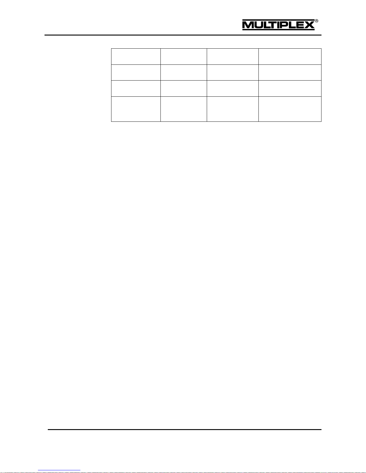
Differences between transmitter versions
Page 12
Introduction
PROFI TX
Page 9
PROFI TX 9
PROFI TX 12
PROFI TX 16
Channels 9 12
16
Model memories
50
100
200
Other
Volume control using
mixers
1.2 V2 software
1.2.1 Update from V1 to V2
Additional files must be installed when updating from software version 1 to
version 2. Refer to section 6.3 "Software update" on page 178 for details.
In version 2.xx, the volume settings are stored in the model memory. The volume is
set to 16 by default for newly created model memories. This setting is not available
in older model memories: The volume is initially set to OFF. You can configure the
desired volume level in the Setup > Volume menu.
1.2.2 New features in V2
1.2.2.1 Speech output
The following information can be output as speech:
remaining operating time (time to empty; in minutes) for the transmitter
flight phase
status of the teacher / student connection
trim position
time markers of the timers
announcement of the altitude
announcement of selected sensor channels
sensor value when a sensor alarm is issued
announcement of the time of day by the alarm clock
Sound and speech output can be customised. Details will be made available in the
Downloads section of our home page by the 3rd quarter 2014.
Page 13

Introduction
Page 10
PROFI TX
1.2.2.2 Volume
The volume can be set by either choosing a fixed value or by configuring
freely assignable controls. We recommend using rotary potentiometers that
are installed on the front (Item No.: 75756).
The variometer volume is configured separately.
With the PROFI TX 16, the volume can also be controlled via mixers.
The volume control data is stored in the model memory.
1.2.2.3 MagicSwitch
The number of MagicSwitches was doubled from 2 to 4.
Each MagicSwitch now has an additional OR input.
1.2.2.4 Switching thresholds
The switching thresholds of controls that are installed on the front were changed
from 50% to 95% (rotary potentiometers are used as switches).
1.2.2.5 Timer
The specialised timers were replaced by universal timers.
Three operating modes are available for each timer: frame, sum, and
interval
The counting mode can be selected: Up or Count down
You can select to have the time announced within 5 minutes before an
alarm occurs or the zero point is passed.
The timers can be renamed as desired.
1.3 Contact
Should you still have any questions regarding your PROFI TX, please feel free to
contact your specialist dealer who will be happy to assist you.
Service partners
The addresses of our service partners are available on our website:
www.multiplex-rc.de
Page 14

Introduction
PROFI TX
Page 11
1.4 About these operating instructions
These operating instructions describe the PROFI TX tray-type transmitter and
contain the following sections:
Section 1 "Introduction" provides an overview of the PROFI TX concept
and information regarding the current firmware version.
Section "Safety instructions" contains important information concerning
safety, intended use and warranty.
Section 2 "Transmitter" describes:
o The PROFI TX hardware.
o How to setup the transmitter for operation.
o Mechanical operations that may have to be carried out on the
transmitter, e.g. installing additional controls.
o How to charge the transmitter battery including battery
management.
o How to switch the transmitter on and off.
o How to perform a range check and the binding procedure.
o How to operate in trainer mode.
o How to trim your model aircraft.
Section 3 "Model templates" describes the model templates available in
the PROFI TX.
Section 4 "The menus" describes the PROFI TX software:
o Navigation within the software.
o The status displays.
o All menus and their parameters.
Section 5 "Operating the transmitter" describes:
o How to operate the transmitter by means of the keypad, the central
wheel and, if necessary, the optional digi-adjusters.
o How to assign controls and switches. This defines which controls
are used to operate the various functions in the transmitter or
model.
Section 6 "Operating the transmitter using the PC" describes how
to connect the transmitter to the PC and the options provided by this
connection.
Section 7 "Creating and customising models" describes step by step
using two examples how to create and configure your own fixed-wing and
helicopter models.
Page 15
Introduction
Page 12
PROFI TX
Section 8 "Speech output & sounds" contains detailed information on
speech output and sound files.
Section 9 "Safety instructions"
Make sure to read and observe the following operating and safety
instructions!
Knowledge of these operating instructions and their observance are a prerequisite
for safe use as well as safe operation and maintenance.
The following basic safety instructions and warnings are an essential component of
these operating instructions and are fundamentally important for product handling.
Keep the operating instructions at hand and pass them on to the new owner on
resale of the product.
Failure to observe the safety instructions can result in property damage, injuries or
even death.
Signal words and their meaning
DANGER identifies an immediate possible dangerous situation with a high risk that
will result in death or severe personal injury if not avoided.
WARNING identifies a possible dangerous situation with a medium risk that may
result in death or (severe) personal injury if not avoided.
CAUTION identifies a possible dangerous situation with a low risk that might result
in minor or moderate personal injury if not avoided.
NOTICE indicates the possibility of misuse which could cause damage to the
product.
INFORMATION that is important for the PROFI TX operator.
Page 16
Introduction
PROFI TX
Page 13
1.5 Basic safety instructions
The following basic safety instructions and warnings are an essential
component of these operating instructions and are fundamentally
important for device handling.
Read the instructions carefully!
Make sure that you have carefully read these operating instructions and the
following safety instructions before setting up the device for operation.
Radio-controlled models are not toys in the usual sense. Assembly, installation, and
operation of the RC system require technical knowledge, care, safety-awareness
and responsibility. Errors or negligence can lead to considerable damage. Since the
manufacturer or the seller does not have any influence and control over the proper
setting up and operation of a model, such risks are expressly pointed out here and
any liability whatsoever is excluded.
A model that goes out of control for whatever reasons can cause significant damage
to property or personal injury. Be aware of safety at all times. Make sure to take out
general liability insurance.
Do not modify the radio control system. Use only original accessories and spare
parts.
If the device is operated in combination with third-party products, ascertain their
quality and functional reliability. Each new or changed combination must undergo
careful functional testing, including a range check. Do not operate the device or
model if there appear to be any problems. First identify the error and troubleshoot it.
In particular, have the radio control transmitter and the receiver inspected at an
authorised MULTIPLEX Service Centre (see section 10.1 "Specifications" on
page 212) at regular intervals (every 2 to 3 years).
Operate the transmitter only in the permissible temperature range (see section 10.1
"Specifications" on page 212). Bear in mind that condensation may form in the
transmitter due to sudden temperature changes (e.g. warm car, cold environment).
Page 17
Introduction
Page 14
PROFI TX
Moisture may impair the function of the transmitter and other components of the
radio control system.
If moisture accumulates in electrical devices, immediately stop using the device,
disconnect it from the power supply and allow it to dry in the open state as far as
possible (up to a few days). Thereafter, perform a careful functional test. In case of
major condensation, have the device inspected at an authorised MULTIPLEX
Service Centre (see section "1.2" on page 9).
Operation of the radio control system is allowed without restrictions within EU
territory and Switzerland.
Program a new model at home in peace. Make sure that the power system of the
model cannot start up unexpectedly. Check all functions carefully. Completely
familiarize yourself with the operation of the transmitter before putting the model
in operation.
Page 18
Introduction
PROFI TX
Page 15
1.6 Safety instructions for the transmitter battery
The transmitter battery powers the device and plays an important role in operational
safety. The charging circuit integrated in the transmitter matches the battery. Do not
charge the battery outside the device.
Batteries are not toys: They must be stored out of the reach of children.
Damaged or defective batteries must not be used and should be disposed of
properly (see section 1.12 "Disposal" on page 22).
Do not heat, incinerate, open or short-circuit rechargeable batteries, do not charge
or discharge them at excessive currents, do not overcharge them, avoid deep
discharge, and do not charge with reversed polarity. Observe of the permissible
temperature range for the battery.
Mishandling the battery incurs the risk of combustion, explosion, chemical burns and
fire.
Page 19

Introduction
Page 16
PROFI TX
1.7 ESD notes for electronic sub-assemblies
The sub-assemblies of radio control transmitters (main circuit board, modules) are
fitted with electrostatically sensitive components. These parts can be destroyed,
suffer imperceptible damage or have their useful life shortened if static discharges
take place (potential equalisation through electro-static discharge) when the subassembly is touched.
The following protective measures are essential if you have to handle
electrostatically sensitive sub-assemblies:
Before fitting or removing such sub-assemblies, equalise the electrical
potential difference between yourself and your environment (e.g. by
touching a heating radiator).
Open the basic device and touch it over a large area in order to equalise
the potential relative to the base unit.
Do not remove any sub-assemblies from their conductive anti-static bags
until you have equalised the potential. Avoid touching electronic components
or solder pads directly. Hold the sub-assembly by the edges of the circuit
board only.
Once removed from the basic device, the sub-assembly should only be
stored in the conductive anti-static bag in which it was delivered. Never allow
the sub-assembly to make direct contact with a conventional, non-ESD
compatible container made of foam, Styrofoam or other plastic.
Page 20
Introduction
PROFI TX
Page 17
1.8 Intended use
The PROFI TX transmitter is intended exclusively for operation of models by
radio control.
Always follow the switching on/off sequence in order to avoid any uncontrolled,
dangerous startup of the power system:
Switching on sequence using the BEC:
1. Disconnect the BEC connector from the receiver.
2. Set the throttle on the transmitter to OFF, then switch on the
transmitter.
3. Connect the power system battery.
4. Connect the BEC connector to the receiver.
Switching off sequence using the BEC:
1. Disconnect the power system battery.
Switching on sequence using the receiver battery:
1. Disconnect the power system battery.
2. Set the throttle on the transmitter to OFF, then switch on the
transmitter.
3. Connect the receiver battery.
4. Connect the power system battery.
Switching off sequence using the receiver battery:
1. Disconnect the power system battery.
2. Disconnect the receiver battery.
Page 21

Introduction
Page 18
PROFI TX
Assemble the model carefully
Install and adjust all control surface linkages in such a way that the surfaces
move smoothly and freely, and are not stalled even at maximum travel. Do
not use the radio control to regularly limit servo travels. Preferable: Adjust
control surface levers and pushrods mechanically and as thoroughly as
possible. Avoid lost motion (sloppy linkages). Use configuration options on
the servo side of the RC transmitter only for fine-tuning.
Observe the above-mentioned guidelines to make full use of the resolution
(positioning accuracy) of your radio control system.
Provide effective protection from vibration to the receiver, battery, servos
and other RC and electronic components. Observe the advice included in
the relevant operating instructions. Balance propellers and rotor blades
before use and replace them at any sign of damage. Install I.C. engines on
vibration-absorbing mounts and replace motors or motor parts which are
damaged or do not run true.
Do not strain or bend cables; protect them against rotating parts.
Keep servo cables as short as possible.
Use cables with sufficient cross-section.
Do not coil up or shorten the receiver aerial. Do not lay the aerial on or close
to electrically conductive components. Deploy aerials outside of fuselages
with a shielding effect (carbon fibre, metallic painted finish).
Ensure that the receiver power supply is of adequate capacity. For servos up
to about 40Ncm torque you can estimate the required battery capacity using
the following formula:
Capacity [mAh] ≥ number of servos x 200 mAh.
Use the next larger size of battery!
Take care to maintain sufficient distance between cables carrying heavy
currents (e.g. electric power system) and the RC system. Especially the
cables between brushless electric motors and their actuators must be kept
as short as possible (guide value: max. 10 to 15 cm).
Page 22
Introduction
PROFI TX
Page 19
Check the model regularly
Free movement and zero backlash of control surfaces and linkages.
Stability and flawless condition of pushrods, linkages, hinge joints, etc.
Carry out a visual check for fractures, cracks, possible shear points etc. on
the model itself, and in its components such as the RC and power systems.
Flawless condition and contact stability of cables and plug connections.
Absolutely essential: Examine the power supply and its wiring, including the
switch harness, and the external condition of the battery.
This entails regular maintenance of the batteries and periodic checks of the
voltage curve and capacity, employing a charge process and battery charger
suitable for the type of battery in use.
Pre-flight checks
Charge the transmitter, receiver and power system batteries carefully to full
capacity, and verify their state of charge at regular intervals.
Ensure that the correct model memory is active on the transmitter.
Carry out a range check (see section 2.6 "Range check" on page 46).
Check the function and effect of all primary and secondary control systems.
If you discover any irregularities, do not fly. Locate the problem, eliminate it, and
then check again.
When operating the model:
If you have never flown a radio-controlled model before, it is highly
recommended you consult an experienced model pilot when getting started.
A trainer (buddy-box) system is ideal for taking the first steps in learning to
fly.
Models should only be operated at suitable sites.
Never fly or drive over or towards spectators.
Do not carry out any high-risk flying or driving manoeuvres.
Know your limits: do not over-estimate your abilities and skills.
If you detect any sign of a problem or interference, land or cease operations
immediately.
Page 23
Introduction
Page 20
PROFI TX
1.9 Liability and indemnification
The model sport with radio-controlled models is a fascinating hobby. However,
model aeroplanes, vehicles and ships are not toys. Their assembly and operation
require a high level of technical knowledge, careful craftsmanship, safetyawareness and responsibility. Errors, inattentiveness or even negligence can
lead to considerable damage to property or severe personal injury. Generally, you
as operator are responsible for any threat arising from your model. This absolute
liability will not be assumed by the manufacturer. This is also applicable in the
event of uncontrollable external influences and interferences. You are expected
to exercise extreme care as operator of a model.
Since manufacturers or dealers cannot have any influence on proper setting up,
maintenance and operation of the model and the radio control system, such risks
are expressly pointed out here.
MULTIPLEX Modellsport GmbH & Co.KG does not assume any liability for loss,
damage or costs which arise through the improper use and operation of our
products, or which are connected with such operation in any way.
As far as is legally permissible, the obligation to provide compensation for
damages, on whatever legal basis, is limited to the invoice amount of the quantity
of MULTIPLEX goods that were directly affected by whatever incident gave rise
to the damage. This does not apply if MULTIPLEX is obliged to accept unlimited
liability in accordance with mandatory law for deliberate or gross negligence.
Furthermore, MULTIPLEX Modellsport GmbH & Co.KG does not extend any
warranty for the completeness and correctness of the documents enclosed with
the radio control components.
Observe also the advice included in the relevant transmitter documentation!
Page 24
Introduction
PROFI TX
Page 21
1.10 Warranty
Our products are covered by the statutory warranty regulations. If you wish to make
a claim under warranty, please contact the model shop where you purchased the
product.
The warranty does not cover defects and malfunctions caused by the following:
improper operation, wrong connections, terminal reversal
use of third-party components; modifications and repairs that were not
carried out at an authorised MULTIPLEX Service Centre
damages caused by the use of force
defects due to improper use and / or normal wear and tear
operation of the equipment outside the technical specifications
Observe the information leaflets included in the relevant transmitter documentation!
1.11 EC declaration of conformity
The PROFI TX devices were assessed in accordance with the relevant harmonised
European directives.
You are therefore the owner of a product whose design fulfils the protective aims of
the European Community relating to the safe operation of equipment.
The detailed declaration of conformity can be downloaded from our website:
www.multiplex-rc.de
under
DOWNLOADS / Product Information
If required, you may also send us your request for the declaration of conformity by
post:
MULTIPLEX Modellsport GmbH & Co.KG
Customer Service
Westliche Gewerbestraße 1
D-75015 Bretten-Gölshausen, Germany
Page 25
Introduction
Page 22
PROFI TX
1.12 Disposal
In the countries of the EU (European Union), electrical equipment must not be
disposed of via the household or residual waste system. Waste equipment must be
taken to your nearest local authority waste collection point or recycling centre.
There, equipment will be disposed of properly and free of charge.
Remove the batteries before disposing of the equipment. (Rechargeable) batteries
are recycled separately.
By returning your waste equipment you can make an important contribution to
protecting the environment.
Recycling of rechargeable batteries
Do not dispose of depleted rechargeable batteries in household waste.
Take them to a suitable recycling system. Rechargeable batteries must be
discharged and short-circuit safe. Tape over the terminals with non-conducting
adhesive tape.
Page 26
Transmitter
PROFI TX
Page 23
2 Transmitter
2.1 Transmitter overview
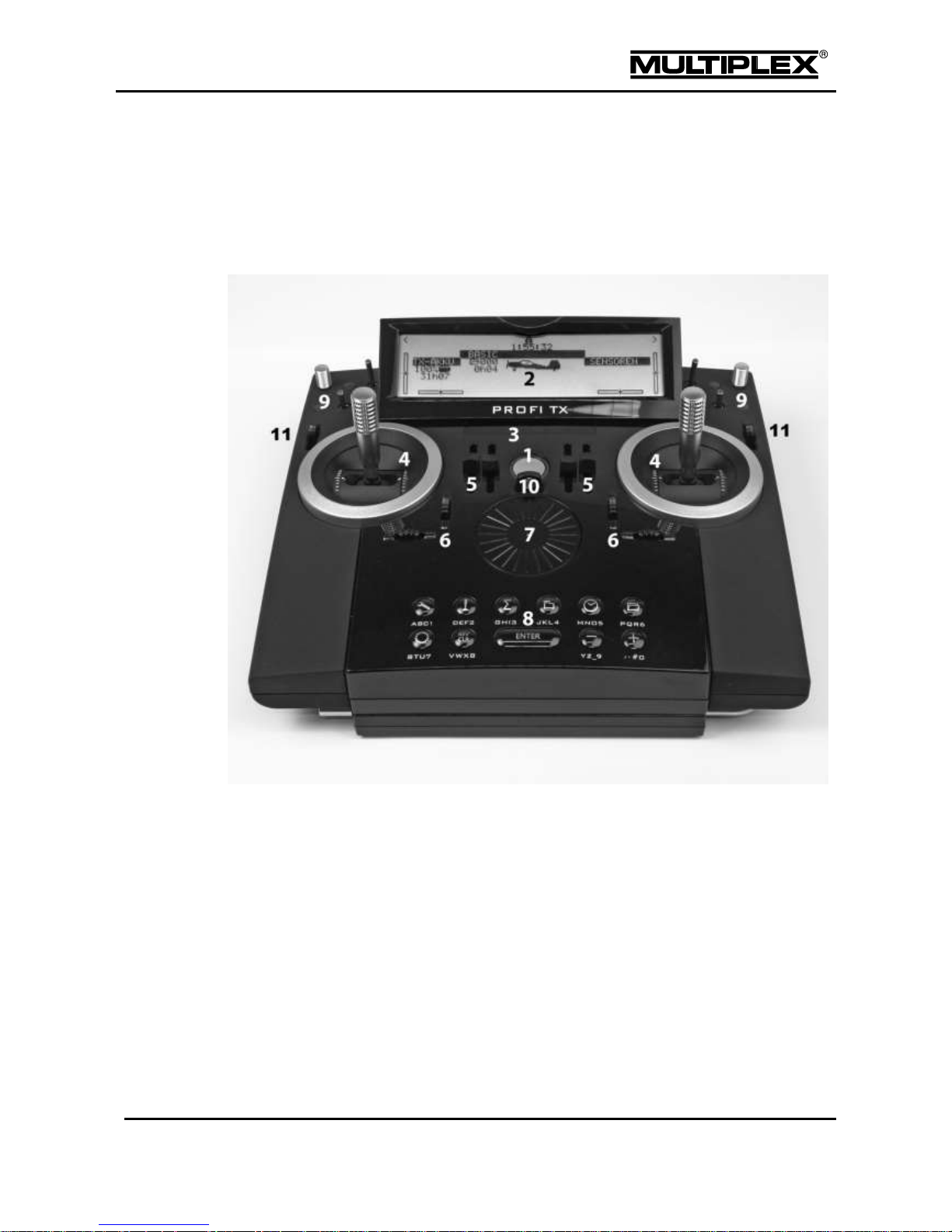
2.1.1 Top view
Figure 1: Top view of the transmitter
1
Power button with annular light (see "Switching the transmitter on / off" on
page 43).
The annular light indicates the status of the RF module during operation (see
"Annular light" on page 24).
2
UV-stable, anti-glare graphic LCD unit (256 x 64 dots) featuring high contrast.
The screen contrast can be optimised (see section 4.3.9 "Transmitter" on
page 114), and the screen can be raised as required.
3
Warning lights for the sensors used on the model. The warning lights indicate
whether the alarm values for certain sensor groups have been exceeded (see
section "Warning lights" on page 25).
Page 27

Transmitter
Page 24
PROFI TX
4
Two ultra-low friction, ball-raced stick units for controlling the 4 primary
control axes.
The stick ratchet for throttle / spoiler can be activated to the right or
left (see section 2.3.2 "Adjusting stick units" on page 33).
Both stick units can be swivelled to suit the pilot’s ergonomic
preferences (see section 2.3.2.1 "Swivelling stick units" on page 33).
The stick tops can be rotated and freely adjusted in length, and are available in
different variants.
5
Two slide potentiometers (controls <E and F>) with position markers for freely
assignable channel and / or switched functions.
6
Buttons for digital trim of the 4 stick units (see section 2.8 "Digital trim" on
page 50).
7
Central wheel for navigating through the menus and editing set values. The
wheel can be turned in increments to the left or right and can be pressed (see
section 5.2 "Operation using the wheel" on page 167).
8
Keypad, consisting of 11 buttons in 2 rows
The 6 buttons in the upper row are used for quick and direct access to
the 6 main menus (see section 5.1.1 "Menu buttons" on page 164).
The 5 buttons in the second row are used for programming (see section
5.1.2 "Buttons for special functions" on page 165).
With the exception of the ENTER button, all the buttons have a dual
function for text input. Text is entered in a similar way to mobile phones
(see section 5.1.3 "Text input" on page 166).
9
Installation slots for additional controls and digi-adjusters (see section 2.3.4
"Installing additional controls" on page 36).
10
Lug for attaching a support strap (# 8 5161 or # 8 5646).
11
Two sliders (controls <G and H>) for channel and / or switched functions.
Annular light
The annular light indicates the status of the RF module during operation:
Yellow flash: Normal mode, full transmitting power.
Red flash: Range check; reduced transmitting power (see page 46).
Flashing orange light: A binding procedure is in progress (see page 47).
Solid light: A PC is or was connected. No RF is generated.
o Yellow: Battery charging is in progress.
o Red: The battery is not charged.
Page 28
Transmitter
PROFI TX
Page 25
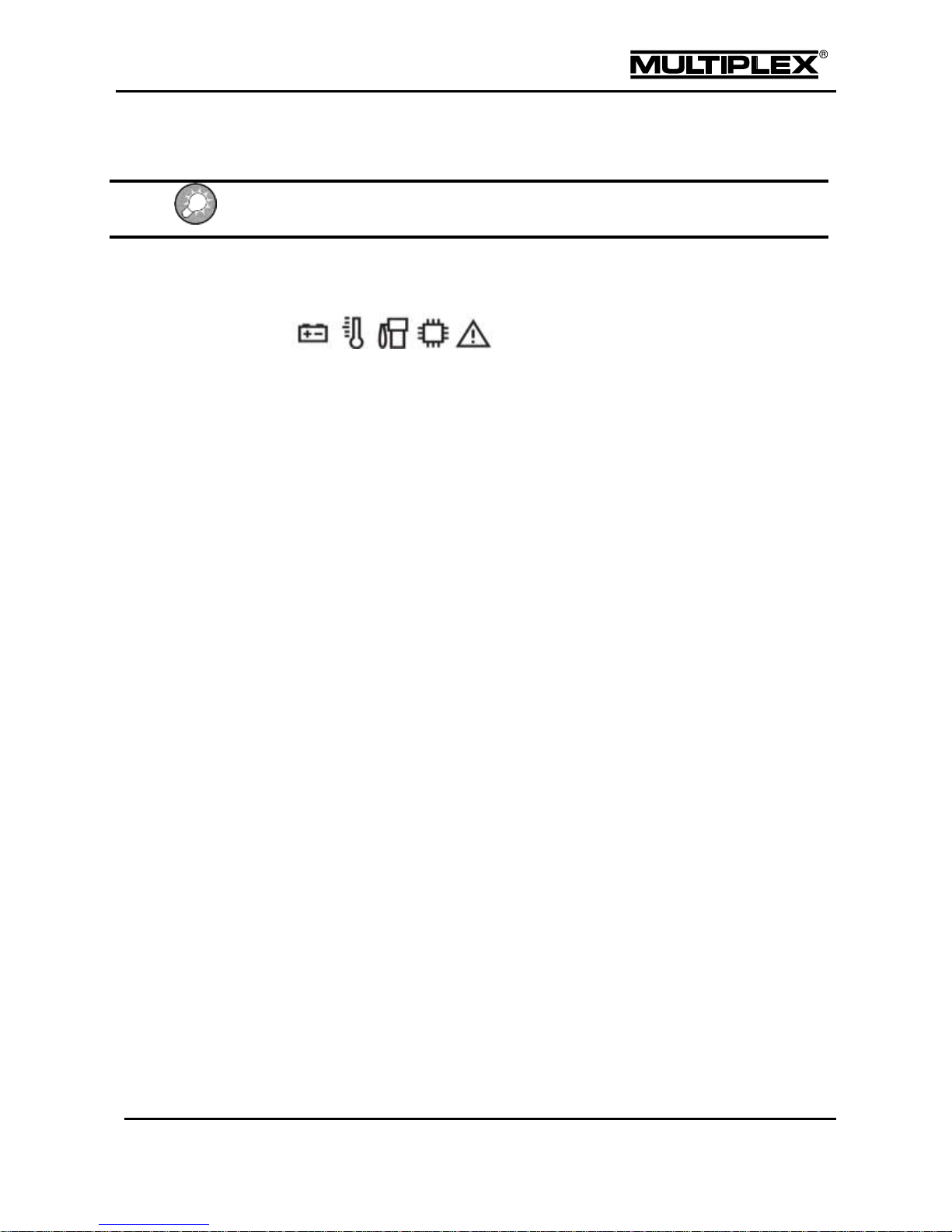
Warning lights
Press the ENTER button to clear the warning bar if status display #2 is shown.
The warning lights serve as markers for the sensor alarms.
The following warning lights are assigned to the sensors:
Battery icon: voltage sensors
Thermometer: temperature sensors
Petrol pump: level and battery charge sensors
IC icon: ECU (Engine Control Unit)
Warning sign: speed and current sensors
Page 29
Transmitter
Page 26
PROFI TX
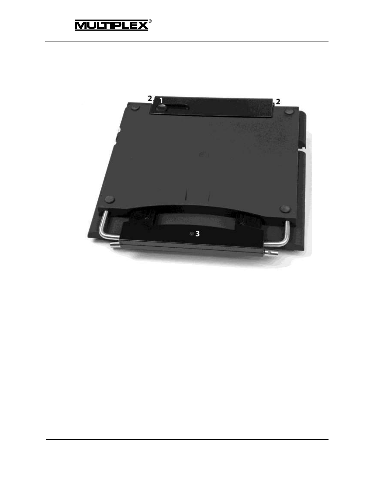
2.1.2 Underside view
Figure 2: Underside view of the transmitter
1
Recessed control for the sliding latch for USB sockets (see section 2.1.5
"Connectors" on page 29)
2
Fasteners for opening the case (see section 2.3.1 "Opening and closing the
case" on page 31)
3
Carry bars
Page 30
Transmitter
PROFI TX
Page 27
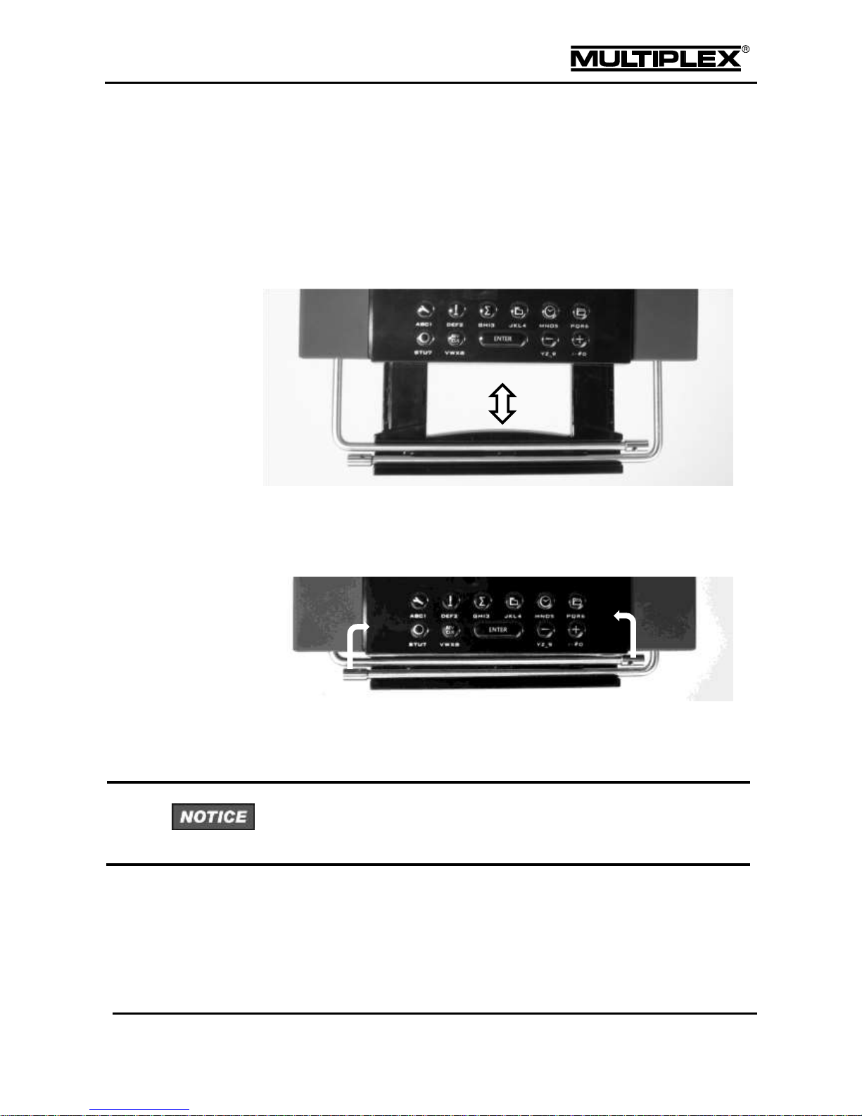
2.1.3 Carry handle / bars
The carry bars are located inside a drawer which also serves as a handle to carry
the transmitter.
2.1.3.1 Carry handle
If you want to use the drawer as a carry handle, pull it out completely (figure). The
carry bars are locked in this position.
2.1.3.2 Carry bars
Pull out the drawer only up to the point where the inside bar is fully exposed. This
is the only position where the bars are unlocked and can be swivelled out (figure).
Carefully swivel out the bars until they snap into place. The drawer can be pulled
out completely to serve as a carry handle or pushed into the back case cover to be
stored away.
Only in this position of the drawer (figure) are the carry bars unlocked. In all other
positions, the carry bars cannot and must not be swivelled out.
Using force will damage the swivel mechanism!
Page 31

Transmitter
Page 28
PROFI TX
2.1.4 The interior
Figure 3: The interior of the transmitter
1
RF module with IOAT aerial
2
Transmitter battery (see section 2.4 "
Transmitter battery" on page 40)
3
Control units
4
microSD card
5
Covers for the slots for controls installable on the front
6
4 slots for additional modules (see section "Installing additional modules" on
page 39)
7
2 clamp terminals for connecting the controls installable on the stick tops
(see section "Installing stick tops with a switch or button" on page 35)
8
TORX screwdriver
Page 32

Transmitter
PROFI TX
Page 29
2.1.5 Connectors
Figure 4: Connectors on the transmitter
1
Headset connector (stereo jack); when a headset is connected, the
loudspeaker of the PROFI TX is switched off
2
Mini USB socket for connecting the PROFI TX to a PC and for charging the
battery via the charging socket (see section 2.4.1 "Charging the battery" on
page 40)
3
USB-A socket for future expansions
Page 33

Transmitter
Page 30
PROFI TX
2.2 Initial setup
The following steps should be performed during initial setup of your PROFI TX.
Refer to the relevant sections listed below for a detailed description.
Briefly charge the battery. It is sufficient to charge the battery for one hour on the
PC (500mA) or for 20 minutes via the plug-in charger (1.5A): Refer to section 2.4
"
Transmitter battery" on page 40 for details.
1. Switch on the transmitter: Press and hold the Power button until the annular
light is fully lit. The device is switched on when you release the button.
Refer to section 2.5.1 "Switching on" on page 44.
2. Select the language to be used in the menus and the texts in the model
templates:
Refer to section "Switching on for the first time" on page 45.
3. Switch off the transmitter: Press the Power button until the annular light turns
off. The device is switched off when you release the button. Refer to section
2.5.2 "Switching off" on page 45.
4. Open the case of the transmitter:
Refer to section 2.3.1 "Opening and closing the case" on page 31.
5. Adjust the stick units to suit your ergonomic preferences.
o If necessary, swivel the stick units:
Refer to section 2.3.2.1 "Swivelling stick units" on page 33.
o Activate the stick ratchet:
Refer to section 2.3.2.2 "Adjusting ratchet, friction and centring
force" on page 34.
6. If necessary, install additional switches:
Refer to section 2.3.4 "Installing additional controls" on page 36.
7. Install the receive system and connect the servos.
Perform the binding procedure to bind the receiver with the transmitter:
Refer to section "Binding" on page 47.
Page 34

Transmitter
PROFI TX
Page 31
2.3 Mechanical operations on the transmitter
2.3.1 Opening and closing the case
Danger of short-circuit!
Switch off the transmitter before opening the case.
Opening the case
1. Switch off the transmitter.
2. Remove the USB and headset cables.
3. Place the transmitter upside down on a soft surface.
4. Press and hold the two fasteners on the side of the screen and gently lift
the back case cover.
5. Release the fasteners, flip up the back case cover and remove it.
Page 35

Transmitter
Page 32
PROFI TX
Closing the case
6. Remove the USB and headset cables.
7. Place the transmitter upside down on a soft surface.
8. Move the controls on the side to the centre position.
9. Place the lower edge of the back case cover vertically onto the case.
10. Swivel the back case cover to the front, push down and press gently to snap it
into place.
Page 36

Transmitter
PROFI TX
Page 33
2.3.2 Adjusting stick units
2.3.2.1 Swivelling stick units
The "natural working axis" of your hands is at a more or less pronounced angle.
The stick units of the PROFI TX can be swivelled to perfectly suit your ergonomic
preferences. The swivelling range is approx. 15°.
Figure 5: Swivelling stick units
Proceed as follows:
1. Using the TORX screwdriver, loosen the three TORX screws retaining the
appropriate stick unit until the unit can be swivelled.
2. Swivel the stick unit to the most comfortable angle for use.
3. Tighten the screws again.
Take care not to over-tighten them or you might strip the threads.
Page 37

Transmitter
Page 34
PROFI TX
2.3.2.2 Adjusting ratchet, friction and centring force
Figure 6: Adjuster screws on the stick
Ratchet and friction
The PROFI TX is supplied as standard with self-centring sticks. The springs for use
with a ratchet or friction system are already fitted to both stick units, and can be
activated quickly and easily.
The screws (2) hold the springs. The screws (3) are used to adjust the level of
ratchet / friction action. The more the screw is tightened, the harder the ratchet or
friction.
If required, you can set a superimposed ratchet / friction action by activating both
springs on one stick. This will help you achieve perfect control as needed.
1. Switch off the transmitter and open it.
2. Using the TORX screwdriver, tighten the TORX screw (turn clockwise) on the
appropriate centring lever (1) to the point where the stick centring action is
completely disabled.
Do not over-tighten the screws. Do not disassemble the centring lever and/or the
centring spring.
(2) Springs for adjusting ratchet or friction
(4) Centring
force
right / left
(1) Deactivate
centring
action
(4) Centring
force forward /
backward
(3) Level of ratchet or friction
Page 38

Transmitter
PROFI TX
Page 35
2.3.3 Installing stick tops with a switch or button
MULTIPLEX® offers three different stick tops with switch or button for the PROFI
TX (see section 10.2 "Accessories" on page 213).
To install a new stick top proceed as follows:
1. Switch off the transmitter and
open it.
2. Remove the battery1.
3. Loosen the grub screw at the
bottom of the stick top (1.5mm
slot-head screwdriver).
Pull off the top from the stick
shaft.
4. Wrap the flexible wires of the
new stick top with a thin
enamelled copper wire. Tightly bend back the section without insulation.
Thread the enamelled copper wire
through the borehole on the stick shaft
until it is visible at the bottom of the stick
unit. Use a pair of pliers to pull the wire
out until you can grab it with your
fingers.
5. Gently pull on the wire until you can
grab the flexible wire with your fingers.
This will be easier if you turn the stick
shaft on the side opposite the point
where the wire exits.
6. Slide the stick top onto the stick shaft, simultaneously pulling the flexible wire
completely through.
7. Tighten the grub screw on the stick top.
8. You can see one three-pin
terminal clamp next to every
1
After re-inserting the battery, date and time need to be set again.
Page 39

Transmitter
Page 36
PROFI TX
stick unit on the main circuit board of the device. Remove the wire.
Clamp the blue flexible wire to the centre terminal and the red wire(s) to the
output terminal(s).
9. Insert the battery and close the transmitter.
10. Switch on the transmitter.
11. Verify that the switch operates correctly.
To test this, assign the new stick switch to any switched function in the
Setup > Assign.Switches menu.
Stick tops
The standard tops can be replaced with the following stick tops (see also
section 10.2 "Accessories" on page 213):
Aluminium stick top, long, with 2-position switch
Item No. 85940
Aluminium stick top, long, with 3-position switch
Item No. 85941
Aluminium stick top, long, with push-button
Item No. 85942
2.3.4 Installing additional controls
You can install 8 controls on each side of the PROFI TX (see section 2.1
"Transmitter overview" on page 23).
The 7 controls can be buttons, 2- or 3-position dip-switches, or rotary
potentiometers in any arrangement.
In addition, a digi-adjuster can be installed on each side. You can assign a
parameter for direct configuration to each digi-adjuster (see section 5.3
"Digi-adjuster" on page 168).
To install a control proceed as follows:
1
Switch off the transmitter.
2
Disconnect the headset and USB cables.
3
Unscrew the knobs from all the digi-adjusters and potentiometers.
Page 40

Transmitter
PROFI TX
Page 37
4
Open the transmitter.
5
Remove the battery.
6
Open the cable cover on the side where you
wish to install the additional control.
When the control is installed on the right
side, the cover of the headset socket must
also be removed. To this end, use a
screwdriver to pry away the clip on the right
side and swivel the cover out to the front.
7
Loosen the 2 screws on the circuit boards
on top of the switch tray using the TORX
screwdriver.
8
Lift off the circuit boards and place them
nearby. Remove the two screws on the
switch tray.
9
Lift out the switch tray and remove the blind
plugs from the required installation slots.
10
Install the controls. Observe the installation
direction for dip-switches: The red cable
must face the transmitter front.
11
Replace the switch tray and secure it using the screws.
12
Replace the circuit boards and secure them using the screws. Replace
the cover over the headset socket and make sure that the clips snap into
place.
13
Refit the connectors of the controls.
14
Close the cap on the slots.
15
Insert the battery and close the transmitter.
Page 41

Transmitter
Page 38
PROFI TX
16
Switch on the transmitter.
17
Verify that the controls operate correctly.
To test this, assign the new controls to any switched function in the
Setup > Assign.Switches menu.
18
Screw the tops of the digi-adjusters and potentiometers back on.
19
Date and time have to be set again in the Timer menu, as the battery
was removed.
Additional controls
The following additional controls can be installed in the PROFI TX (see also
section 10.2 "Accessories" on page 213):
2-position switch (micro), short
Item No. 75750
2-position switch (micro), long
Item No. 75751
3-position switch (micro), short
Item No. 75752
3-position switch (micro), long
Item No. 75753
Digi-adjuster
Item No. 75755
Rotary knob (micro)
Item No. 75756
Push-button (micro)
Item No. 75754
Page 42

Transmitter
PROFI TX
Page 39
2.3.5 Installing additional modules
You can add four modules to the PROFI TX.
Never install two identical modules!
When these operating instructions were released for print, only the COPILOT
module (item no. 45184) was available (see section 10.2 "Accessories" on
page 213).
To install a module proceed as follows:
1
Switch off the transmitter.
2
Disconnect the headset and USB cables.
3
Open the transmitter.
4
Insert the module in one of the 4 slots
and make sure that the respective fixing
clip faces the transmitter centre and is
aligned with a fixing bore on the central
plastic part.
5
Tighten the screw supplied.
Take care not to over-tighten the screw.
6
Close the transmitter.
7
Switch on the transmitter.
8
Verify that the module operates correctly. Refer to the section "Trainer mode"
on page 49 for more details.
Page 43

Transmitter
Page 40
PROFI TX
2.4 Transmitter battery
The PROFI TX is powered by a robust and durable LiFePO4 battery. The battery is
installed with the electronic system for battery management in a welded case. If the
battery is new, the battery capacity of 4000mAh provides an operating time of more
than 30 hours. Additionally installed components increase power consumption and
shorten the operating time. If the device is exposed to temperatures below -10°C,
the operating time is significantly reduced.
2.4.1 Charging the battery
The PROFI TX features two USB sockets at the front on the right-hand side of the
case, which are protected by a sliding latch. The mini USB socket is used for
charging (see section 2.1.5 "Connectors" on page 29).
The following options are available for charging the PROFI TX:
Via your PC or laptop
Via the MULTIPLEX USB car plug-in charger 12V DC
(item no. 145533)
Via the MULTIPLEX USB plug-in charger 100-240V AC
(item no. 145534, see section 10.2, "Accessories" on page 213)
The transmitter must not be connected to a charger when no battery is installed!
Without a consumer, the charger can provide unacceptably high output voltages.
These voltages can damage the transmitter.
Page 44

Transmitter
PROFI TX
Page 41
2.4.1.1 Charging via the PC
Proceed as follows:
1. Switch off the PROFI TX.
2. Lift the device. The recessed control for the sliding latch is located on the
underside of the case.
3. Slide the sliding latch towards the device centre.
4. Switch on the PC. Connect the supplied USB cable to a USB socket on the
PC and to the mini USB socket on the PROFI TX.
o The PROFI TX starts automatically in charging mode.
o The figure below is shown on the screen.
Maximum current: 500mA.
The PROFI TX logs into the PC as mass storage with the name
"PROFI TX".
Upon first time use, the PC automatically installs device drivers. Do not switch
off the PC and/or the transmitter and do not disconnect the USB cable while the
installation is in progress. This may take several minutes. Some operating systems
require an active Internet connection for this process.
If you press and hold the Power button until the annular light is fully lit, the
transmitter switches from charging mode to normal mode. The PROFI TX logs
off from the PC as USB mass storage and logs in again as a game controller
(see section 6 "Operating the transmitter " on page 176).
The RF module is disabled while a USB connection is established. It also remains
switched off after disconnection. Otherwise, the RF module would be re-enabled
when the host (PC, laptop, etc.) is switched off.
Page 45

Transmitter
Page 42
PROFI TX
2.4.1.2 Charging the battery using the plug-in charger
Proceed as follows:
1. Lift the device (the recessed control for the sliding latch is located on the
underside of the case).
2. Slide the sliding latch towards the device centre.
3. Connect the supplied USB cable to the plug-in charger and to the mini
USB socket on the PROFI TX.
4. Connect the plug-in charger to a mains outlet.
The plug-in charger icon is shown on the right side of the screen and the state
of charge and the charging current are displayed on the left. Maximum current
(depending on charger and state of charge): 1500mA.
2.4.2 Removing the battery
1
Open the transmitter.
2
Slide the battery to the left towards the
empty area in the battery dock.
3
Remove the battery.
4
Place the battery on a non-conducting, dry surface.
2.4.3 Inserting the battery
1
Insert the battery on the left side of the
battery dock, with the rounded side facing
to the left.
2
Slide the battery to the right until the stop
is reached.
Page 46

Transmitter
PROFI TX
Page 43
2.4.4 Battery management
The PROFI TX records the current during transmitter operation and while charging
the transmitter battery. The available battery charge is calculated on the basis of
the power meter reading, the temperature and the voltage. The remaining
operating time (time to empty) is calculated from charge and current and is shown
on status display #2 (see page 88). The calculation takes into account that current
consumption slightly decreases with decreasing battery voltage.
Battery alarm
If the remaining operating time falls below a configurable threshold, the remaining
operating time is announced with increasing frequency. The "TX-BATT." section on
the left side of status display #2 flashes.
The factory setting for the alarm threshold is 60 minutes. This value can be
changed in the Setup > Transmitter > Battery alarm menu (see
section 4.3.9 "Transmitter" on page 114).
Self-discharge
If the transmitter is stored for a prolonged period, the available battery charge is
estimated based on the idle voltage when the transmitter is switched on. For this
reason, the displayed charge and time to empty are not initially very accurate.
After one to two charge / discharge cycles the original accuracy is restored.
Under-voltage cut-off
If the operating voltage falls below 2.8V, the device is automatically switched off
without further warning. If the voltage is below 2.9V, it cannot be switched on: The
following message is briefly displayed on the screen: BATTERY DOWN!
Charge the transmitter battery!
If voltage is low, recharge the battery as soon as possible (within 1-2 days) to avoid
damage due to deep discharge. Observe the notes on charging (see section 2.4 "
Transmitter battery" on page 40).
Page 47

Transmitter
Page 44
PROFI TX
2.5 Switching the transmitter on / off
Charge the transmitter battery!
The PROFI TX is supplied with a partially charged transmitter battery. You should
charge the battery prior to setup. Please observe the notes on charging (see
section 2.4 "
Transmitter battery" on page 40).
2.5.1 Switching on
To switch on the device proceed as follows:
1. Press and hold the Power button until the annular light is fully lit. The device is
switched on when you release the button.
If you press and hold the Power button for a prolonged period, the annular light turns
off again and the device is not switched on when you release the button (power-on
protection).
2. At this point, either the safety check prompt is displayed on the screen:
Or the language selection screen is shown, if the menu language has not yet
been selected (see section "Switching on for the first time" on page 45).
The RF module is switched off until the safety check is completed to prevent the
servo from moving to an undesired position.
3. Check if safety-related controls such as landing gear switches, flight phase
switches, and throttle sticks are in the proper position.
4. Press a button on the keypad: The safety check is completed, the RF module
is switched on, and status display #2 is shown.
Page 48

Transmitter
PROFI TX
Page 45
You can switch the safety check on and off in the Memory > Safety check
menu. The safety check is activated by default when you create new model
templates (see page 162).
Switching on in Binding mode
Press and hold the ¡ button during startup until the status display is shown.
Switching on for range check
Press and hold the § button during startup until "Safety check" or the status
display is shown: The device starts up with reduced transmitting power when the
range check is performed (see section 2.6 "Range check" on page 46).
Switching on for the first time
The very first time you switch on the PROFI TX is a special case. A language
selection menu is shown on the screen after startup. Here, you select the
language for:
1. Menus
2. Names of mixers, timers and control functions in the model templates
3. Speech output
The language is selected using the keypad (up/down/ENTER). If you select
"skip/später", transmitter functionality is restricted: Only one model memory is
available and its contents are not stored on the SD card when the device is
switched off. The menu is shown in English.
2.5.2 Switching off
Press and hold the Power button until the red annular light turns off completely to
switch off the device. The device is switched off when the annular ring turns off and
the button is released. If you press and hold the button for a prolonged period, the
annular ring returns to ready status. Now, you can release the button without the
device switching off (power-off protection).
Page 49

Transmitter
Page 46
PROFI TX
2.6 Range check
Regular range checks are necessary for ensuring the reliable functioning of the
radio control system and for timely detection of changes in transmission properties.
Always perform a range check after:
installing, modifying or rearranging components in the model,
reusing components in the model that were involved in a crash,
observing irregularities when operating the model.
The transmitting power can be significantly reduced for the range check, enabling
short distances between transmitter and model.
While the range check is active the status displays #2 to #8 show the flashing
message: RANGE! with the annular ring flashing red. A warning is announced every
minute to alert the operator. The warning is only announced when your are not
navigating in menus so as not to disturb you when performing configurations.
Recommended minimum distance: 40m to 100m, depending on receiver type.
Refer to the receiver operating instructions for detailed information.
Always perform a range check before starting up the model.
A second person must always be present for the range check to secure and
observe the model.
Large metal objects within or in close proximity to the checking range (wire fences,
cars) affect the result of the range check.
Page 50

Transmitter
PROFI TX
Page 47
Procedure
1. If the model is fitted with a power system, switch it off!
2. Press and hold the §button on the transmitter as you switch the transmitter
on.
3. Switch on the receiver.
4. In the Servo > Test run menu, activate the test run for a control function,
e.g. Elevator. This allows you to check that the receive system responds to
control commands with distinct, regular movements of the control surfaces.
5. Increase the distance between transmitter and model. You have reached the
range limit when the servos start to jitter.
6. Repeat the check with the power system running. Secure the model. Perform
the check using throttle positions that vary between idle and full throttle. In
case of electric power systems, the most significant interferences occur at
half throttle.
The range should not diminish significantly.
7. Otherwise, eliminate the cause of the interference (power system, installed
position of the receive system with power supply).
Factors influencing the radio range
The following factors have significant influence on the radio range:
Environmental conditions
Hilltops, ground characteristics, type of terrain, and the atmospheric
conditions affect radio range.
Receiver technology and sophistication
Technically sophisticated receivers have a greater range than simple,
cheap receivers.
Installation situation in the model
Installation position / arrangement of the aerials and the distance to
batteries, power systems, servos, ignition systems, metal / carbon fibre
parts influence the radio range.
Binding
The binding procedure binds the receiver with the transmitter.
M-LINK uses "frequency hopping" and "spread spectrum".
No fixed transmission channel is used for "frequency hopping", but all 39 channels
are used in a sequence that is defined by the transmitter.
Page 51

Transmitter
Page 48
PROFI TX
For "spread spectrum", every data bit is coded in 64 bits (spread). This procedure
provides a high level of immunity to interference. During binding, the transmitter
passes "hopping sequence“, "spreading code", and "response time" to the receiver.
Procedure
The binding procedure can be started in 2 ways: via the keypad during startup or
via the menu.
Starting the binding procedure when the device is switched on:
1. Press and hold the ¡ button for the full duration of the transmitter startup
procedure.
o The annular ring of the Power button is flashing in orange and the flashing
message "BINDING" is shown in the status displays #2 to #8.
2. Now, switch on the receiver while pressing and holding the Set button (connect
the power supply).
o The receiver LED is flashing rapidly.
3. The binding procedure is completed within a few seconds:
o The annular light returns to flashing yellow.
o The receiver LED is flashing slowly.
o The servos that are connected to the receiver can now be controlled.
Starting the binding procedure via the menu
1. Switch off the receiver and switch on the transmitter.
o Press the ¡ button to open the "Setup" menu.
o Use the wheel to select the "M-LINK" menu item. Press the wheel.
o Open the "Binding" menu item. Press the wheel . The input field OFF is
now highlighted.
o Turn the wheel to the right: The text "seeking.." is now displayed in the
input field and the annular light of the Power button is flashing in orange.
The transmitter is searching for a receiver in binding mode.
o You can cancel the binding procedure at any time: Turn the wheel to the
left. The previous condition is restored.
2. Now, switch on the receiver while pressing and holding the Set button (connect
the power supply).
o The receiver LED is flashing rapidly.
3. The binding procedure is completed within a few seconds:
Page 52

Transmitter
PROFI TX
Page 49
o The input field briefly shows the text "OFF" and then indicates the
detected type: "RX", "RX-ID", "MultiFlight", "Teacher" or "Student".
o The annular light returns to flashing yellow.
o The receiver LED is flashing slowly.
o The servos that are connected to the receiver can now be controlled.
If the binding procedure does not complete automatically within a few seconds,
move the transmitter front closer to the receiver aerial(s).
The Setup > M-LINK > Binding menu item indicates if and what type of receiver
is currently connected to the PROFI TX.
The ID is displayed for ID receivers.
2.7 Trainer mode
The trainer mode (teacher / student) is the safest method for beginners to get
started in model sport.
An experienced model pilot has control over the model as the teacher. The trainer
can transfer control functions to the student by operating a button. Initially these
will be individual control functions, and later all the main control functions will be
transferred.
The PROFI TX can be configured either as a teacher transmitter or as a student
transmitter. The teacher and student transmitters are inter-connected using a
second M-LINK radio link.
If the radio link between the student and the teacher is lost, all the control functions
are returned to the teacher.
Student mode
In Student mode, the control signals of the sticks and sliders are transferred via MLINK to the teacher transmitter (without trim and travel settings).
A second PROFI TX with COPILOT module or another MULTIPLEX transmitter
with trainer stick can be used as the teacher transmitter.
Page 53

Transmitter
Page 50
PROFI TX
Refer to "Training" on page 99 for details.
Teacher mode
A free switch on the teacher transmitter and the COPILOT module are required for
the Teacher mode (see section 10.2 "Accessories" on page 213):
Refer to section 2.3.4 "Installing additional controls" on page 36 for
information on how to install a switch.
Refer to section 5.4.2 "Assign.Switches" on page 173 for information on how
to assign the switch to the trainer function.
Refer to section 2.3.5 "Installing additional modules" on page 39 for
information on how to install the COPILOT module.
In Teacher mode, the selected control functions can be controlled by the student
transmitter. These control functions are selected in the Setup > Training menu.
The selection list is only available in Teacher mode.
2.8 Digital trim
2.8.1 Overview
"Trimming" refers to the adjustment of the model aircraft to fly straight and level
when you leave the sticks exactly at centre.
Digital trim has two essential advantages:
Digital trim buttons do not have any physical position corresponding to the
actual trim value (which is the case for conventional trim with trim sliders).
The digital trim position is displayed on the screen, and any change to the
trim values is stored in the model memory. If you switch model memories,
there is no need to move the trim sliders to the correct position to suit the
model. The correct trims are immediately available.
In models for which you have set up multiple flight phases each flight phase
has its own trim memory, i.e. it is simple to trim each flight phase accurately,
and independently of the trims in the other phases.
Example
The model aircraft should fly straight and level when you leave the sticks exactly at
centre. If this is not the case, the neutral point of the causal control function should
be corrected / trimmed.
Page 54

Transmitter
PROFI TX
Page 51
Centre trim
The PROFI TX enables digital trim on each of the 4 stick axes.
"Centre trim" is applied to the main control functions "Aileron", "Elevator", and
"Rudder". For "Throttle" you can choose between idle and centre trim. The centre
trim only affects the control centre, but not the end-travels. Unlike standard trim,
this offers the advantage that no control travel must be reserved for trimming:
the servo travel is used fully.
Both servo end-points remain unchanged, regardless of the current trim position.
2.8.2 Trim buttons
On the PROFI TX, trimming is carried out using the trim buttons arranged below
and to the side of each stick unit (see section 2.1.1 " Top view" on page 23).
Every time you press a button the associated control axis is trimmed in the
direction in which the pressure is applied to the button. If you press and hold the
trim button for more than about 0.8 sec., the trim value changes continuously until
you release the button again (AUTO-REPEAT function). When the trim reaches
the neutral position, the AUTO-REPEAT function stops briefly.
Each trim increment is accompanied by an audible signal. On reaching the neutral
position or the end-point, specific audible signals are emitted.
As an option, the current trim value can be announced when the trim button is
released. You can activate this announcement in the Setup > Transmitter >
Sounds menu (see section 4.3.9 "Transmitter" on page 114).
2.8.3 On-screen trim display
Graphic display
The trim positions are displayed as bars on both sides and at the bottom of the
screen in the status displays #2 to #8:
Figure 7: On-screen trim display
Page 55

Transmitter
Page 52
PROFI TX
Starting from the centre position, the trim range is 20 increments in both directions.
The trim increment (step, or adjustment rate) can be set to any of the following
values: 0.5%, 1.5%, 2.5%, 3.5% (ControlFunctions > respective control
function, Step size parameter, see section 4.4 "4.4ControlFunctions main
menu" on page 118).
Switching the step size changes the trim value percentage since the number of
stored trim increments remains the same. This means if you alter the trim increment
size, you must remember to re-trim the model.
The design of the graphic trim display can be selected (Setup > Transmitter >
Screen, Trim graph parameter, see section 4.3.9 "Transmitter" on page 114).
Page 56

Transmitter
PROFI TX
Page 53
2.9 microSD card
2.9.1 Replacing the microSD card
Open the transmitter.
Use a finger nail to carefully pull the metal card bracket (top part of the
socket) towards the transmitter centre to release the card bracket.
Flip up the card bracket and remove the card.
Insert a new card into the card bracket (terminals facing to the back and
down).
Fold down the card bracket. Push the bracket with the card slightly back
until it snaps into place.
2.9.2 microSD card from a different transmitter
When inserting a card that was used in different transmitter, you must
briefly remove the transmitter battery before switching on the transmitter.
This erases the copy of the last model memory from the microcontroller
RAM. Erasing the model memory prevents the transmitter from using the
RAM copy further and accidentally overwriting the model memory with the
same number on the new card when the transmitter is switched off.
2.9.3 New microSD card
Switch on the PC. Open the "Computer" or "My Computer" pane in the file
explorer.
Switch off the transmitter. Connect the transmitter to the PC via the
USB socket. After a few moments, you see an additional drive. That is
the SD card in the PROFI TX.
o Right-click the new drive to open the context menu.
o Select "Format". Make the following selection in the next menu:
file system: FAT; allocation unit size: 32 kilobytes; quick format
o Click "Start".
Rename the card to "PROFI TX":
o Right-click the new drive to open the context menu.
o Select "Properties".
o Enter the text "PROFI TX" in the input field.
Page 57

Transmitter
Page 54
PROFI TX
o Click "OK".
Now, copy the directory structure to the PROFI TX that is described below.
A zip file containing this directory structure is available in the Downloads
section of our home page.
2.9.3.1 Directory structure on the microSD card
The microSD card must contain the following 3 folders in the root directory:
AUDIO
Contains the 3 subdirectories DE, EN and FR. The
subdirectories contain sound and speech output files for
each language.
DATA
The model memories are stored in this folder. The file names
are written in capitals and start with "PTX" followed by the
model number (3-digit with leading zeros). The file name
extension is .MDL.
UPDATE
Updates are placed in this folder. If the transmitter detects an
update file during startup, the update procedure is started.
The file is deleted upon successful completion of the update
procedure.
Page 58

Model templates
PROFI TX
Seite 55
3 Model templates
Templates for fixed-wing models
BASIC, see page 58
ACRO, see page 61
GLIDER+, see page 61
DELTA WING, see page 67
FLYING WING, see page 69
BIG SCALE, see page 71
Templates for helicopter models:
FUNCOPTER, see page 75
HELI FBL, see page 76
HELImech., see page 77
HELIccpm, see page 77
Templates for land- or water-based models and tracked vehicles
CAR / TRUCK, see page 80
SHIP / BOAT, see page 82
TRACKED V., see page 84
Switch assignment
In the PROFI TX, all the switches can be installed and connected as needed.
For this reason, switched functions that are usually assigned to dip-switches
or buttons cannot be pre-set in the model templates. You have to configure
these assignments yourself according to the existing switches.
Using timers
The Frame, Sum, and Interval timers are only functional if a switch has been
assigned to them. The same control that is used for the Throttle control function
is assigned to the sum timer in all model templates. For this reason, this timer is
immediately functional. You activate the other timers by assigning a switch to them.
Control mixers (Ctrl.Mix)
The Ctrl.Mix control mixers are not initialised in the templates.
Page 59

Model templates
Seite 56
PROFI TX
3.1 Templates for fixed-wing models
All the templates for fixed-wing models use similar names for the 15 control
functions. Only the Throttle and Spoiler assignments differ:
For power models, Throttle is assigned to a stick, Spoiler is assigned to
slider <E.
For glider-type models, Spoiler is assigned to the stick, Throttle is assigned
to slider <E.
Controls assignment, control function, and settings
Control function
Control
Setting
Parameter
Aileron
[Mode]
Trim
FP4
Step size
Expo
FP4
D/R
Travel
FP4
0%
1.5%
0%
100%
100%
Elevator
[Mode]
Trim
FP4
Step size
Expo
FP4
D/R
Travel
FP4
0%
1.5%
0%
100%
100%
Rudder
[Mode]
Trim
FP4
Step size
Expo
FP4
D/R
Travel
FP4
0%
1.5%
0%
100%
100%
Throttle
BASIC, ACRO, DELTA
WING, BIG SCALE:
stick
GLIDER+: <E
Trim
FP4
Step size
Mode
Expo
Slow
0%
1.5%
HALF
0%
0.0s
Page 60

Model templates
PROFI TX
Seite 57
Spoiler
BASIC, ACRO, DELTA
WING, BIG SCALE: <E
GLIDER+: stick
Slow
Fixed value
FP4
0.0s
OFF
Flap1
F>
Slow
Fixed value
FP4
0.0s
OFF
Retract.Gear
---
Slow
Fixed value
FP4
0.0s
OFF
Towing dog
---
-
-
Wheel Brake
---
-
-
Gyro
---
Type of Gyro
Damping/Headin
g
FP4
Suppression
Heading
Control
OFF
Mixture
---
-
-
Aux-1
---
Slow
Fixed value
FP4
0.0s
OFF
Aux-2
---
Slow
Fixed value
FP4
0.0s
OFF
Aux-3
---
Slow
Fixed value
FP4
0.0s
OFF
Aux-4
---
Slow
Fixed value
FP4
0.0s
OFF
FP4
= 4 flight phases
1
Camber-changing flap
Page 61

Model templates
Seite 58
PROFI TX
3.1.1 BASIC model template
This model template is designed for simple power or glider-type models and
for models without aileron.
This model template should also be used for model flying simulators.
Servo assignment
If you install a second aileron servo to provide separate linkage for the ailerons,
simply assign the Aileron function to a free servo (see "Assign" starting from
page 149). Would you like to raise the ailerons as an airbrake? In that case, assign
the AILERONS+ mixer to both aileron servos at the same position. The extended
airbrake will cause major load distribution changes: Change the elevator to
ELEVATOR+. It is then possible to compensate for the effects of Throttle and
Spoiler (airbrake).
Pre-defined mixers on the control side, with 2 more that can be defined by
the operator.
Name
Mixer inputs
Options & settings
Value
Makes it easier to fly accurate turns:
Combi-Switch
Ail <> rudder
Ail < rudder
OFF
Optimises flying turns:
Differnt.Ail
Aileron
Mode
OFF
Function
1
Aileron
2
Elevator
3
Rudder
4
Power system
Page 62

Model templates
PROFI TX
Seite 59
Name
Mixer inputs
Options & settings
Value
Differnt.Ail
50%
Pre-defined mixers on the servo side in the BASIC template
Name
Mixer inputs
Options & settings
Value
Compensation:
ELEVATOR+
Elevator
š
Up and down
travels are
asymmetrical
100%
100%
Throttle-T
(untrimmed)
›-
Single-sided
travel, with
deadband
OFF
OFF
Spoiler
Single-sided
travel, with
intermediate point
OFF
OFF
Do you use a V-tail model? Reset the control functions "Rudder" and
"ELEVATOR+" to "V-TAIL+" in the "Servo > Assign" menu.
V-TAIL+
Elevator
š
Up and down
travels are
asymmetrical
70%
70%
Rudder
š 2
Right and left
travels are
asymmetrical,
2 directions
70%
70%
Throttle-T
(untrimmed)
›-
Single-sided
travel, with
deadband
OFF
OFF
Spoiler
œ
Single-sided
travel, with
intermediate
point
OFF
OFF
For airbrake and aileron differential. Requires 2 AILERONS+ servos.
AILERONS+
Aileron
™ 2
Travels are
symmetrical
100%
100%
Page 63

Model templates
Seite 60
PROFI TX
Spoiler
›+
Single-sided
travel, with
offset
OFF
OFF
Page 64

Model templates
PROFI TX
Seite 61
3.1.2 ACRO model template
The ACRO model template is suitable for power models with up to 4 flaps,
optionally with snap flap.
Pre-defined mixers on the control side, with 2 more that can be defined by
the operator.
Name
Mixer inputs
Options & settings
Value (%)
Combi-Switch
Ail <> rudder
Ail < rudder
OFF
Differnt.Ail
Aileron
Mode
Differnt.Ail
+SPOILER
50%
Pre-defined mixers on the servo side
Name
Mixer inputs
Options & settings
Value (%)
ELEVATOR+
Elevator
š
Up and down
travels are
asymmetrical
100%
100%
Function
1
AILERONS+
2
ELEVATOR+
3
Rudder
4
Power system
5
AILERONS+
Page 65

Model templates
Seite 62
PROFI TX
Name
Mixer inputs
Options & settings
Value (%)
Throttle-T
(untrimmed)
›-
Single-sided
travel, with
deadband
OFF
OFF
Landing flaps
œ
Single-sided
travel, with
intermediate point
OFF
OFF
Spoiler
œ
Single-sided
travel, with
intermediate point
OFF
OFF
V-TAIL+
Elevator
š
Up and down
travels are
asymmetrical
70%
70%
Rudder
š 2
Right and left
travels are
asymmetrical, 2
directions
70%
70%
Throttle-T
(untrimmed)
›-
Single-sided
travel, with
deadband
OFF
OFF
Landing flaps
œ
Single-sided
travel, with
intermediate point
OFF
OFF
Spoiler
œ
Single-sided
travel, with
intermediate point
OFF
OFF
AILERONS+
Aileron
™+2
Travel is
symmetrical, 2
directions, with
offset
100%
100%
Page 66

Model templates
PROFI TX
Seite 63
Name
Mixer inputs
Options & settings
Value (%)
Landing flaps
(increase in lift)
›+
Single-sided
travel, with offset
OFF
OFF
Spoiler (airbrake)
œ
Single-sided
travel, with
intermediate point
OFF
OFF
Elevator-T (snap
flap)
š
Up and down
travels are
asymmetrical
OFF
OFF
FLAPS+
Flaps (increase in
lift)
›+
Single-sided
travel, with offset
100%
OFF
Aileron
š 2
Up and down
travels are
asymmetrical, 2
directions
OFF
OFF
Spoiler (airbrake)
œ
Single-sided
travel, with
intermediate point
OFF
OFF
Elevator-T (snap
flap)
š
Up and down
travels are
asymmetrical
OFF
OFF
Page 67

Model templates
Seite 64
PROFI TX
3.1.3 GLIDER+ model template
The model template is suitable for glider-type models with up to 8 flaps,
optionally with snap flap.
Servo assignment
Pre-defined mixers on the control side, with 2 more that can be defined by
the operator.
Name
Mixer inputs
Options & settings
Value
Combi-Switch
Ail <> rudder
Ail < rudder
OFF
Differnt.Ail
Aileron
Mode
Differnt.Ail
ON
50%
Pre-defined mixers on the servo side
Name
Mixer inputs
Options & settings
V
a
l
u
e
ELEVATOR+
Elevator
š
Up and down
travels are
asymmetrical
1
0
0
%
1
0
0
%
Function
1+5
AILERONS+
2
ELEVATOR+
3
Rudder
4
Throttle
6+7
FLAP_INNR+
8+9
Spoiler
Page 68

Model templates
PROFI TX
Seite 65
Name
Mixer inputs
Options & settings
V
a
l
u
e
Spoiler
œ
Single-sided
travel, with
intermediate point
O
F
F
O
F
F
Flap
š
Up and down
travels are
asymmetrical
O
F
F
O
F
F
Throttle-T
(without trim)
›-
Single-sided
travel, with
deadband
O
F
F
O
F
F
V-TAIL+
Elevator
š
Up and down
travels are
asymmetrical
7
0
%
7
0
%
Rudder
š 2
Right and left
travels are
asymmetrical
7
0
%
7
0
%
Spoiler
›+
Single-sided
travel, with offset
O
F
F
O
F
F
Throttle-T
(untrimmed)
›-
Single-sided
travel, with
deadband
O
F
F
O
F
F
AILERONS+
Aileron
™ 2
Travel is
symmetrical, 2
directions
1
0
0
%
1
0
0
%
Spoiler
›+
Single-sided
travel, with offset
O
F
F
O
F
F
Page 69

Model templates
Seite 66
PROFI TX
Name
Mixer inputs
Options & settings
V
a
l
u
e
Flap
š
Up and down
travels are
asymmetrical
O
F
F
O
F
F
Elevator-T
(snap flap)
š
Up and down
travels are
asymmetrical
O
F
F
O
F
F
FLAP_INNR+
FLAP_CNTR+ 1
Flap
š
Up and down travels
are asymmetrical
OFF
OFF
Spoiler
›+
Single-sided travel,
with offset
OFF
OFF
Aileron
š 2
Up and down travels
are asymmetrical
50%
50%
1
For centre flap pairs.
Page 70

Model templates
PROFI TX
Seite 67
3.1.4 DELTA WING model template
This model template is suitable for delta wing models.
Pre-defined mixers on the control side, with 2 more that can be defined by
the operator.
Name
Mixer inputs
Options & settings
Value
Combi-Switch
Ail <> rudder
Ail < rudder
OFF
Differnt.Ail
Aileron
Mode
Differnt.Ail
ON
50%
Pre-defined mixers on the servo side
Name
Mixer inputs
Options & settings
Value
DELTA+
Aileron
™ 2
Up and down travels
are symmetrical
70%
70%
Elevator
š
Up and down travels
are asymmetrical
70%
70%
Throttle-T
›-
Single-sided travel,
with deadband
OFF
OFF
Function
1+2
DELTA+
3
Rudder
4
Throttle
Page 71

Model templates
Seite 68
PROFI TX
Name
Mixer inputs
Options & settings
Value
V-TAIL+
Elevator
š
Up and down travels
are asymmetrical
70%
70%
Rudder
š 2
Right and left travels
are asymmetrical
70%
70%
Throttle-T
›-
Single-sided travel,
with deadband
OFF
OFF
Page 72

Model templates
PROFI TX
Seite 69
3.1.5 FLYING WING model template
This model template is suitable for models with up to 4 flaps.
Servo assignment
Pre-defined mixers on the control side, with 2 more that can be defined by
the operator.
Name
Mixer inputs
Options & settings
Value
Combi-Switch
Ail <> rudder
Ail < rudder
OFF
Differnt.Ail
Aileron
Mode
Differnt.Ail
ON
100%
Function
1+5
FLAP_INNR+
2+3
FLAP_OUTR+
4
Throttle
Page 73

Model templates
Seite 70
PROFI TX
Pre-defined mixers on the servo side
Name
Mixer inputs
Options & settings
Value
FLAP_INNR+
Inboard flap pair
Aileron
š 2
Up and down
travels are
asymmetrical
70%
70%
Elevator
š
Up and down
travels are
asymmetrical
70%
70%
Flap
(camber-changing
flaps)
š
Up and down
travels are
asymmetrical
OFF
OFF
Spoiler
›+
Single-sided
travel, with offset
OFF
OFF
Throttle-T
›-
Single-sided
travel, with
deadband
OFF
OFF
FLAP_OUTR+
Outboard flap
pair
Aileron
(inboard)
™ 2
Up and down
travels are
symmetrical
70%
70%
Elevator
š
Up and down
travels are
asymmetrical
70%
70%
Flap
(camber-changing
flaps)
š
Up and down
travels are
asymmetrical
OFF
OFF
Spoiler
›+
Single-sided
travel, with offset
OFF
OFF
Throttle-T
›-
Single-sided
travel, with
deadband
OFF
OFF
Page 74

Model templates
PROFI TX
Seite 71
3.1.6 BIG SCALE model template
This model template is suitable for large-scale power models with 2 elevator servos
and landing flaps.
Servo assignment
Pre-defined mixers on the control side, with 2 more that can be defined by
the operator.
Name
Mixer inputs
Options & settings
Value (%)
Combi-Switch
Ail <> rudder
Ail < rudder
OFF
Differnt.Ail
Aileron
Mode
Differnt.Ail
+SPOILER
50%
Pre-defined mixers on the servo side
Name
Mixer inputs
Options & settings
Value (%)
ELEVATOR+
Elevator
š
Up and down
travels are
asymmetrical
100%
100%
Spoiler
œ
Single-sided travel,
with centre
OFF
OFF
Flap
š
Up and down
travels are
asymmetrical
OFF
OFF
Function
1+6
AILERONS+
2+5
FLAPS+
3+4
ELEVATOR+
7
Rudder
8
Throttle
Page 75

Model templates
Seite 72
PROFI TX
Throttle-T
(untrimmed)
›-
Single-sided travel,
with deadband
OFF
OFF
V-TAIL+
Elevator
š
Up and down
travels are
asymmetrical
70%
70%
Rudder
š 2
Right and left
travels are
asymmetrical, 2
directions
70%
70%
Spoiler
›+
Single-sided travel,
with offset
OFF
OFF
Throttle-T
(untrimmed)
›-
Single-sided travel,
with deadband
OFF
OFF
AILERONS+
Aileron
™+2
Travel is
symmetrical, 2
directions, with
offset
100%
100%
Landing flaps
(increase in lift)
›+
Single-sided travel,
with offset
OFF
OFF
Spoiler (airbrake)
œ
Single-sided travel,
with intermediate
point
OFF
OFF
Elevator-T (snap
flap)
š
Up and down
travels are
asymmetrical
OFF
OFF
FLAPS+
Landing flaps
(increase in lift)
›+
Single-sided travel,
with offset
100%
OFF
Aileron
š 2
Up and down
travels are
asymmetrical, 2
directions
50%
50%
Spoiler (airbrake)
œ
Single-sided travel,
with intermediate
point
OFF
OFF
Elevator-T (snap
flap)
š
Up and down
travels are
asymmetrical
OFF
OFF
Page 76

Model templates
PROFI TX
Seite 73
3.2 Templates for helicopter models
Model templates are provided for 4 helicopter types:
FUNCOPTER for throttle-controlled electric helicopters
eHELI FBL for flybarless helicopters
eHELIccpm for electric helicopters with electronic main rotor mixer
HELIccpm for I.C. helicopters with electronic main rotor mixer
HELImech for I.C. helicopters with mechanical main rotor mixer
Controls assignment, control function, and settings
Control function
Control
Setting
Parameter
Aileron
[Mode]
Trim
FP4
Step size
Expo
FP4
D/R
Travel
FP4
0%
1.5%
0%
100%
100%
Elevator
[Mode]
Trim
FP4
Step size
Expo
FP4
D/R
Travel
FP4
0%
1.5%
0%
100%
100%
Rudder
[Mode]
Trim
FP4
Step size
Expo
FP4
D/R
Travel
FP4
0%
1.5%
0%
100%
100%
Throttle
¢
Governor
Trim
FP4
Step size
Mode
Expo
Slow
ON
e
/ OFF
v
0%
1.5%
HALF
0%
0.0s
Aux-1
---
Slow
Fixed value
FP4
0.0s
OFF
Aux-2
---
Slow
Fixed value
FP4
0.0s
OFF
Retract.Gear
---
Slow
Fixed value
FP4
0.0s
OFF
Switch-1
--- - -
Switch-2
--- - -
Gyro
<E
Type of Gyro
Heading
FP4
Damping
/Control
Suppression
Heading
Control: <E
OFF
Page 77

Model templates
Seite 74
PROFI TX
Switch-3 e
Mixture i
---
-
-
Aux-3
---
Slow
Fixed value
FP4
0.0s
OFF
Aux-4
---
Slow
Fixed value
FP4
0.0s
OFF
Collective
same as Throttle
Slow
Fixed value
FP4
0.0s
OFF
Thr.Limiter
F>
Slow
Fixed value
FP4
0.0s
OFF
FP4
= 4 flight phases
i
= I.C. engine
e
= electric motor
All the helicopter templates contain the same set of mixers:
four freely configurable, flight phase-enabled control mixers;
e.g. to mix Aileron, Elevator, Rudder in Throttle.
Tail rotor mixer up to 4 servos
Main rotor mixer
Name
Mixer inputs
Settings
Value
TAIL ROTOR
Rudder, Collective
Offset
Coll.+/-
Coll. origin
Rudd.Diff.
OFF
OFF
0%
OFF
MAINROTOR-R.
Rudder, Elevator,
Collective
Geometry
Rotation
Lever +/-
90%
0°
0%
MAINROTOR-L.
Rudder, Elevator,
Collective
MAINROTOR-FB
Rudder, Elevator,
Collective
MAINROTOR-4
Rudder, Elevator,
Collective
Page 78

Model templates
PROFI TX
Seite 75
3.2.1 FUNCOPTER model template
This model template is suitable for throttle-controlled helicopters with electric
motor. This template cannot be adapted to the other helicopter templates as the
collective pitch channel is not available.
Servo assignment
Servo
FUNCOPTER assignment
1
Aileron
2
Elevator
3
Rudder
4
Collective
5
Throttle
6
Gyro
7..16
--------- (free)
Page 79

Model templates
Seite 76
PROFI TX
3.2.2 eHeli FBL model template
In the basic configuration, this model template is optimised for helicopters with
flybarless controller. The classic configuration can easily be restored by assigning
tail rotor mixers and main rotor mixers on the servo side.
The template is equally suited to collective pitch-controlled electric helicopters with
mechanical main rotor mixer. The "Governor" mode option is activated for Throttle.
Switch off this option if you prefer to work with throttle curves (see "Throttle
(helicopter)", page 124).
Servo assignment
Servo
FBL assignment
Classic assignment with mixers
(restore to flybars)
1
Aileron
MAINROTOR-FB
2
Elevator
MAINROTOR-L.
3
Rudder
TAIL ROTOR
4
Collective
MAINROTOR-R.
5
Throttle
Throttle
6
Gyro
Gyro
7..16
--------- (free)
Page 80

Model templates
PROFI TX
Seite 77
3.2.3 eHeliccpm model template
For collective pitch-controlled electric helicopters with main rotor for electronic
mixing (Collective Cyclic Pitch Mixer).
The "Governor" mode option is activated for Throttle. Switch off this option if you
prefer to work with throttle curves (see "Throttle (helicopter)", page 124).
Function
1
MAINROTOR-FB
2
MAINROTOR-L.
3
TAIL ROTOR
4
MAINROTOR-FB
5
Throttle
6
Gyro
Mixer
Name
Mixer inputs
Settings
Value
TAIL ROTOR
Aileron, Collective
"Collective" and "Offset"
are switched off if the
gyro operates in
Heading-hold mode.
Offset
FP4
Coll.+
Coll.-
FP4
Origin
Rudd.Diff.
FP4
OFF
OFF
OFF
0%
OFF
MAINROTOR-R.
Rudder, Elevator,
Collective
Geometry
Rotation
Lever +/-
120%
0°
0%
MAINROTOR-L.
Rudder, Elevator,
Collective
MAINROTOR-FB
Rudder, Elevator,
Collective
MAINROTOR-4
Rudder, Elevator,
Collective
FP4
= 4 flight phases; for helicopters, the fourth flight phase is always AUTOROT
(auto-rotation).
Page 81

Model templates
Seite 78
PROFI TX
3.2.4 HELIccpm model template
For collective pitch-controlled I.C. helicopters with main rotor for electronic mixing
(Collective Cyclic Pitch Mixer).
Governor mode is switched off in the throttle channel. The Switch-3 control
function was replaced by Mixture for mixture configuration.
If you use a speed controller, switch on the Governor mode to deactivate the
throttle curve (page 124).
Function
1
MAINROTOR-FB
2
MAINROTOR-L.
3
TAIL ROTOR
4
MAINROTOR-FB
5
Throttle
6
Gyro
Mixer
Name
Mixer inputs
Settings
Value
TAIL ROTOR
Aileron, Collective
"Collective" and "Offset" are switched off
if the gyro operates in Heading-hold
mode.
Offset
FP4
Coll.+
Coll.-
FP4
Origin
Rudd.Diff.
FP4
OFF
OFF
OFF
0%
OFF
MAINROTOR-R.
Rudder, Elevator, Collective
Geometry
Rotation
Lever +/-
120%
0°
0%
MAINROTOR-L.
Rudder, Elevator, Collective
MAINROTOR-FB
Rudder, Elevator, Collective
MAINROTOR-4
Rudder, Elevator, Collective
FP4
= 4 flight phases; in templates for helicopters, the fourth flight phase is always
AUTOROT (auto-rotation).
Page 82

Model templates
PROFI TX
Seite 79
3.2.5 HELImech. model template
This template has been optimised for collective pitch-controlled I.C. helicopters with
mechanically mixed main rotor.
Governor mode is switched off in the throttle channel. The Switch-3 control
function was replaced by Mixture for mixture configuration.
Function
1
Aileron
2
Elevator
3
Rudder
4
Collective
5
Throttle
Mixer
Name
Mixer inputs
Settings
Value
TAIL ROTOR
Aileron1, Collective
Offset
Coll.+
Coll.-
Origin
Rudd.Diff.
OFF
OFF
OFF
0%
OFF
To convert the configured helicopter to electronic mixing, you just need to rename
the Aileron, Elevator, and Collective servos to MAINROTOR-L,
MAINROTOR-R, etc. in the Servo > Assign menu. The main rotor mixer is then
available in the Mixer menu.
1
"Collective" and "Offset" are switched off automatically if the gyro operates in
Heading mode.
Page 83

Model templates
Seite 80
PROFI TX
3.3 Templates for land- or water-based models and tracked vehicles
3.3.1 CAR / TRUCK model template
This model template is suitable for all types of vehicle models.
The control functions Support Legs, Ramp, Light, and Aux-1 to Aux-4
provide the Slow function. This allows operating support legs and ramp at a
realistically slow speed. Smooth transition for Light is also possible.
Flight phase switching originates from model flying, as the names suggests. This
function has been left activated for vehicle models. Smart modellers will have good
ideas for practical application.
Control function assignments and names can be changed as required.
This template does not contain pre-defined mixers. To personalise control,
4 mixers on the control side and 7 mixers on the servo side are provided,
each with eight inputs.
Controls assignment, control function, and settings
Control function
Control
Parameter
Value
Gimbal h
Horizontal stick axis.
Assignment by means
of controls mode.
Trim
FP4
Step size
Expo
FP4
D/R
Travel
FP4
0%
1.5%
0%
100%
100%
Gimbal v
Vertical stick axis.
Assignment by means
of controls mode.
Trim
FP4
Step size
Expo
FP4
D/R
Travel
FP4
0%
1.5%
0%
100%
100%
Steering
Horizontal stick axis.
Assignment by means
of controls mode.
Trim
FP4
Step size
Expo
FP4
D/R
Travel
FP4
0%
1.5%
0%
100%
100%
Page 84

Model templates
PROFI TX
Seite 81
Throttle
¢
Trim
FP4
Step size
Mode
Expo
Slow
0%
1.5%
CNTR
0%
0.0s
Support Legs
---
Slow
Fixed value
FP4
0.0s
OFF
Ramp
---
Slow
Fixed value
FP4
0.0s
OFF
Light
---
Slow
Fixed value
FP4
0.0s
OFF
Headlight
---
-
-
Horn
---
-
-
Gear
---
-
-
Sound
---
-
-
Aux-1
---
Slow
Fixed value
FP4
0.0s
OFF
Aux-2
---
Slow
Fixed value
FP4
0.0s
OFF
Aux-3
---
Slow
Fixed value
FP4
0.0s
OFF
Aux-4
---
Slow
Fixed value
FP4
0.0s
OFF
FP4
= 4 flight phases
Servo assignment
Servo
Control function / mixer
Curve points
1
Steering
3
2
Throttle
3
3 -
unused
Page 85

Model templates
Seite 82
PROFI TX
3.3.2 SHIP / BOAT model template
This model template is suitable for all types of water-based models.
The control functions Spoiler, Flap, Light, and Aux-1 to Aux-3 provide the
Slow function. This allows operating support legs and ramp at a realistically slow
speed. Smooth transition for Light is also possible.
Flight phase switching originates from model flying, as the names suggests. We left
this function activated for boat / ship models. Inventive modellers will have good
ideas for practical application.
Control function assignments and names can be changed as required.
This template does not contain pre-defined mixers. To personalise control,
4 mixers on the control side and 7 mixers on the servo side are provided,
each with eight inputs.
Controls assignment, control function, and settings
Control
function
Control
Setting
Parameter
Gimbal h
Horizontal stick
axis. Assignment
by means of
controls mode.
Trim
FP4
Step size
Expo
FP4
D/R
Travel
FP4
0%
1.5%
0%
100%
100%
Gimbal v
Vertical stick axis.
Assignment by
means of controls
mode.
Trim
FP4
Step size
Expo
FP4
D/R
Travel
FP4
0%
1.5%
0%
100%
100%
Rudder
Horizontal stick
axis. Assignment
by means of
controls mode.
Trim
FP4
Step size
Expo
FP4
D/R
Travel
FP4
0%
1.5%
0%
100%
100%
Throttle
¢
Trim
FP4
Step size
0%
1.5%
Page 86

Model templates
PROFI TX
Seite 83
Control
function
Control
Setting
Parameter
Mode
Expo
Slow
HALF
0%
0.0s
Flap
---
Slow
Fixed value
FP4
0.0s
OFF
Spoiler
---
Slow
Fixed value
FP4
0.0s
OFF
Light
---
Slow
Fixed value
FP4
0.0s
OFF
Headlight
---
-
-
Horn
---
-
-
Gear
---
-
-
Sound
---
-
-
Mixture
---
Slow
Fixed value
FP4
0.0s
OFF
Aux-1
---
Slow
Fixed value
FP4
0.0s
OFF
Aux-2
---
Slow
Fixed value
FP4
0.0s
OFF
Aux-3
---
Slow
Fixed value
FP4
0.0s
OFF
FP4
= 4 flight phases
Servo assignment
Servo
Control function / mixer
Curve points
1
Rudder
3
2
Throttle
3
3 - 16
not assigned
Page 87

Model templates
Seite 84
PROFI TX
3.3.3 TRACKED V. model template
This model template is suitable for tracked vehicles.
Control function assignments and names can be changed as required.
Completed tracked vehicle models typically contain a functional building block that
combines "Throttle" and "Steering" for the two power systems.
If you are using 2 separate speed controllers, it is recommended to change the
servo assignment for Steering and Throttle to TRACK+ (page 149).
TRACK+ stands for a mixer that combines "Throttle" and "Steering". You configure
the required settings in the £ Mixer menu (page 132).
Set a small deadband value in the mixer for Steering. If "Steering" and "Throttle"
are assigned to the same stick unit, opening the throttle often involves a small
steering movement. Applying a deadband to "Steering" solves this problem.
To personalise control, 4 mixers on the control side and 6 mixers on the servo side
are provided, each with eight inputs.
Controls assignment, control function, and settings
Control function
Control
Setting
Parameter
Turret turn
Horizontal stick axis.
Assignment by
means of controls
mode.
Trim
FP4
Step size
Expo
FP4
D/R
Travel
FP4
0%
1.5%
0%
100%
100%
Gun up/down
Vertical stick axis.
Assignment by
means of controls
mode.
Trim
FP4
Step size
Expo
FP4
D/R
Travel
FP4
0%
1.5%
0%
100%
100%
Steering
Horizontal stick axis.
Assignment by
means of controls
mode.
Trim
FP4
Step size
Expo
FP4
D/R
Travel
FP4
0%
1.5%
0%
100%
100%
Throttle
¢
Trim
FP4
Step size
Mode
Expo
Slow
0%
1.5%
CNTR
0%
0.0s
Weapon sel.
---
Slow
Fixed value
FP4
0.0s
OFF
Gear
---
Slow
Fixed value
FP4
0.0s
OFF
Page 88

Model templates
PROFI TX
Seite 85
Aux-1
---
Slow
Fixed value
FP4
0.0s
OFF
Light
--- - -
Headlight
--- - -
Gyro
---
Type of Gyro
Damping/Heading
FP4
/Control
Suppression
Heading
---
OFF
Horn
--- - -
Aux-2
---
Slow
Fixed value
FP4
0.0s
OFF
Aux-3
---
Slow
Fixed value
FP4
0.0s
OFF
Aux-4
---
Slow
Fixed value
FP4
0.0s
OFF
Aux-5
---
Slow
Fixed value
FP4
0.0s
OFF
FP4
= 4 flight phases
Servo assignment
Servo
Control function / mixer
Curve point
1
Steering optional TRACK+
3
2
Throttle optional TRACK+
2
3
Turret turn
3
4
Gun up/down
3
5
Weapon sel.
3
6 - 16
unused
Mixer
Name
Mixer inputs
Options & settings
Value
TRACK+
Steering
™-2
Travel is symmetrical, 2
directions, with
deadband
50%
50%
Throttle
š
Forward and backward
travels are
asymmetrical
OFF
OFF
Page 89

MULTIPLEX Modellsport GmbH & Co.KG • Westliche Gewerbestraße 1 • Bretten • Germany
©MULTIPLEX 2014 • Printed in Germany
www.multiplex-rc.de
Page 90

The menus
PROFI TX
Page 87
4 The menus
The PROFI TX software is divided into status displays and menus that are
structured in several levels.
4.1 Status displays
The 8 status displays provide information about transmitter, model and sensors.
The status display is shown after transmitter startup or when exiting the main
menus.
Press the + or – buttons or use the central wheel to toggle between screens. Every
clockwise increment on the central wheel cycles to the next status display (see also
section 5 "Operating the transmitter" on page 164).
Status display #2 is always active when the device is switched on or when a
different memory is selected.
4.1.1 Status display #1
Turn the wheel to the left. Status display #1 provides an overview of the current
battery and device status:
The device name is shown in the first line. The text can be edited (menu:
Setup > Transmitter > User data > Name parameter, see section
4.3.9 "Transmitter" on page 114).
The left half of the screen provides information about the battery, e.g. battery
voltage, remaining operating time (time to empty), etc.
The right half of the table provides information about the device, e.g. serial
number, total uptime count, etc.
Page 91

The menus
Page 88
PROFI TX
4.1.2 Status display #2
1
Digi-adjuster
Set values and their names, which can be edited using the retro-fittable
digi-adjusters.
The padlock icon in the centre opens when the values are enabled for
editing (see section 5.3 "Digi-adjuster" on page 168).
2
TX-BATT. (TX is short for "transmitter")
Battery charge of the transmitter
Remaining operating time.
These displays start to flash when the remaining operating time (time to
empty) reaches the set alarm time (menu: Setup > Transmitter >
Battery alarm parameter, see section 4.3.9 "Transmitter" on page 114).
From then on, the remaining operating time (time to empty) is announced.
Towards the end, the predicted operating time reduce quickly since
additional power is consumed by the announcements. For this reason, we
have included a small buffer.
3
Model memories
Name of the model memory (inverted as heading)
Below the name: model memory number, uptime count for the model
and the respective ID number, if an ID receiver is used.
Next to the name: icon for the type of model used
3 2145
6
6
Page 92

The menus
PROFI TX
Page 89
4
Current time. An asterisk next to the time indicates that the alarm clock
function is activated.
The following warnings are displayed in capital letters.
MEMORY ERROR!
Displayed when errors occur while loading a
model memory. (page 163)
RANGE!
Transmitting power is reduced for the range
check. (page 95)
RF ERROR!
The RF component is defective.
STUDENT MODE!
The Student mode is enabled.
STUDENT
Only in Teacher mode: The selected control
functions are transferred to the student.
MULTIFLIGHT
A MULTIFlight stick was detected: The mixers
on the servo side are switched off.
5
Sensor display on status display #2
Displays the values for sensors 0, 1, and 15 if a receiver with downlink
is used. The value is shown crossed out if no sensor signal is received
for several seconds.
If the sensor reports an alarm:
The sensor value starts to flash.
The appropriate warning light for the sensor group below the screen
starts to flash (see section 2.1.1 " Top view" on page 23).
The device also starts to vibrate if the vibration alarm is activated
(see section 4.3.5.2 "Announce & Alert" on page 103).
If the sensor clears the alarm the value stops flashing. The vibration alarm
and warning light remain active until they are cleared by pressing the
ENTER button.
Notice: In other status displays the ENTER button has different
functions.
Page 93

The menus
Page 90
PROFI TX
6
Trim display
Trim settings for the 4 stick axes. The trim display can be customised
in the Setup > Transmitter menu.
Page 94

The menus
PROFI TX
Page 91
4.1.3 Status display #3
Status display #3 provides an overview of the timers (see section 4.7 "Timer main
menu" on page 152). The other elements are identical to status display #2.
1
Battery status (see section 4.1.2 "Status display #2" on page 88)
2
Timers:
Counting direction of the respective timer
Indication of the timer type
Assigned switch
3
Name of the model memory or status of the digi-adjusters, if used (see
section 4.1.2 "Status display #2" on page 88)
4
Values for the sensor addresses 0, 1, and 15 (see section 4.1.2 "Status
display #2" on page 88)
5
Trim display (see section 4.1.2 "Status display #2" on page 88).
Pressing the REV/CLR button in status display #3 resets all timers.
31245
5
Page 95

The menus
Page 92
PROFI TX
4.1.4 Status displays #4 to #8
The status displays #4 to #8 show three sensor values each.
1
Sensors:
Sensor address
Sensor name
Sensor value
Unit
The inverted display of a line indicates that the sensor reports an alarm.
The value is shown crossed out if no sensor signal is received for several
seconds.
The minimum / maximum values are displayed while pressing and holding
the ENTER button. This is only possible if a receiver with downlink provides
data to display!
2
Alternative:
Status of the digi-adjusters, if used (see section 4.1.2 "Status display
#2" on page 88).
Name of the model memory, if no digi-adjuster is assigned.
3
Trim display (see section 4.1.2 "Status display #2" on page 88).
All minimum / maximum memories are erased when you press the
REV/CLR button in the status displays #4 to #8.
123
3
Page 96

The menus
PROFI TX
Page 93
4.2 Menu structure
The PROFI TX menus are structured in several levels:
Main menus
The 6 main menus are opened via the 6 direct menu access buttons (see
section 5.1.1 "Menu buttons" on page 164).
The main menus only provide links leading to the menus themselves.
Each link is always indicated by a succeeding series of 4 full stops.
Menus
The menus can contain both links to sub-menus and parameters.
Sub-menus
The sub-menus only contain parameters.
Parameter
Parameters are set values which appear in menus and sub-menus. Some only
provide information, but others can be edited.
Uneditable parameters are skipped when browsing.
Navigation in the menus
You can use the buttons or the central wheel to navigate through the menus:
1. Press one of the direct access buttons to open the respective main menu.
2. Use the central wheel or press the + or – buttons to select a menu item.
3. Press the wheel or the ENTER button to access the respective sub-menu.
4. Press the wheel or the ENTER button to move to an input field.
Refer to section 5 "Operating the transmitter" on page 164 for detailed information
on how to navigate in menus and enter values.
An ▼ or ▲ arrow on the left edge indicates that the menu contains more lines than
can be displayed on screen.
Continue to browse using the central wheel or the + / – buttons to scroll to the top or
end of the list.
Page 97

The menus
Page 94
PROFI TX
4.3 Setup main menu
Overview
Volume
Volume control
M-LINK
Binding, Failsafe, etc.
Flight phases
Enabling flight phases, names, transition
Training
Training mode
Sensors
Vario. & Altitude
Settings for variometer and altitude
announcements
Announce & Alert
Vibration alarm, announcements, announcement
interval
Edit name
Entering and editing sensor names
Assign.Controls
Mode (stick assignment), names, assignment
Assign.Switches
TriggerPoint
Trigger points of the proportional controls
MagicSwitch
Logical combination of switches
Assignments
Which switch switches which function?
Define mixer
Transmitter
Sounds
Switching off specific sounds and
announcements
Miscellaneous
settings
Battery alarm, Contrast, etc.
User data
PIN, name of the owner, language
Page 98

The menus
PROFI TX
Page 95
Opening the menu
To open the main menu: Button
4.3.1 Volume
The general volume and the volume of the variometer tone are configured
separately.
The figure below illustrates the default configuration of a newly created model
memory. The following options are available:
Assign.Contr.: You can use any freely assignable control as volume
actuator. This also includes virtual switches (MagicSwitch and flight
phases). The assigned control is used when the fixed value is set to OFF.
Fixed value: The setting range is OFF to 25.
The default setting is 16. When OFF is selected, volume control is
transferred to the assigned control. If no control is assigned the device
remains muted.
Special features:
General volume: When the volume is switched on using a control, the
announcement sequence of the sensor data is restarted.
Variometer tone: When the volume is switched on using a control, the
altitude is announced once.
PROFI TX 16 only: Servo 16 can be used as volume actuator. Complex
volume control scenarios can be implemented using mixers, e.g. the
variometer tone can be muted when pushing/pulling and opening the
throttle.
Page 99

The menus
Page 96
PROFI TX
4.3.2 M-LINK
The radio link functions are set in the M-LINK menu.
Range check
When performing a range check, the transmitting power is significantly
reduced to allow shorter distances between transmitter and model
(see section 2.6 "Range check" on page 46).
Set Failsafe
The current servo positions are stored in the receiver.
If Failsafe positions were stored in the receiver, the servos return to these
positions after 0.5 seconds.
o Use the respective PROFI TX controls to move the servos
(control surfaces) of your model to the desired positions.
o Set the value to ON. After a few moments, it reverts to OFF.
o Check the Failsafe function by switching the transmitter off.
FastResponse
FastResponse reduces the transmission cycle from 21ms to 14ms. This
reduces the response time for control commands. Only 12 servos can be
controlled when FastResponse is active.
Not all servos work properly with FastResponse. Incompatible servos may vibrate
excessively in idle position. Check your servo before starting off on the first flight.
FastResponse has a noticeable effect only on extremely agile models that are
equipped with ultra-fast servos.
Page 100

The menus
PROFI TX
Page 97
Binding
Activates the binding procedure and displays the current binding status (see
section "Binding" on page 47).
RX-ID:
The binding procedure is completed. If the receiver has an ID,
this ID number is displayed.
seeking..
The device is locating the receiver, the binding procedure is in
progress.
4.3.3 Flight phases
It is useful to have different settings and trims for specific flight phases when flying
models. The flight phases technology in the PROFI TX provides an easy and
convenient way to realize this. You can copy settings for one flight phase to
another, disable flight phases if they are not needed, assign switches to flight
phases, etc.
After switching to a different flight phase, the name of the new flight phase is
announced. If the flight phase is disabled, the flight phase is not switched. The
operator is alerted of the disabled flight phase by an announcement.
Refer to section 7.2.10 "Working with flight phases" on page 205 for information on
how to work with flight phases, assign switches to flight phases, disable / enable
flight phases, etc.
Flight phase number (1, 2, 3, or 4)
Identifies the flight phase in other menus. In the control function menus, all
settings that can differ between flight phases are accompanied by the
respective identifying number 1 to 4 for the flight phase.
 Loading...