

Page 1
Contents
lntroduction
PRoFI mc 3010
welcome
About this
The legal side
to the
manual .................
Quickstart
I. The transmitter
hardware
The
Transmitter
Opening
changing
Transmitter back
lnside the
Cable comDartment.
Activating
Charging
Slow
The
keypad
The
menu svslem
The
Tra nsmitte r co
Special-purpose
"Operations"
The
How to use
Changing
(PPMZ
front face. notes on oDeration
and closing the
the RF module
panel
transmitter:
the connectors
the stick
ratchet ..............
the transmitter
charging,
keypad and
rapid-charging
the menu system
...............
ntrol s a n d switches
menus
"Status"
or
the operating
transmission
PPMg,
PCM) .................
Page
the transmilter
.........
Adiusting
Animoortantdifference...................................................31
....i,
..........................4
transmitter,
.......................5
......................................................6
..7
What it does, how
battery
Memories
and lists
...............7
...............8
period
mode
display
...............
.............................13
timer
..................9
...........
..............'12
"Transmitter
"
EXPORT' and
"Mx"
The
"SHIFT"
The
How to switch
"NAME"
The
How to enter
"TRlM"
The
How to check
Control" copy
memory - the
menu:
models ......................
menu:
or change a
menu:
and correct
controls
you
"
IMPORT" copy
it up
set
mode
point
of
model name ............................43
the trim sliders
Page
...............................-....42
mode ...........................42
no return
.......................42
........................44
Powered
"BIG
models:
LIFT"
"RC1/F3A'
"
MIRAGE"
Helicopters:
,
HELIBOY'
"
RANGER"
,
BK-'117"
The assigning
Why do
How
we have to assign?
to assign the transmitter
How to assign servos
Adiusting
How to
reverse servo rotation
How to adjust servo
to adjust servo
How
How to
How to
limit
make travel
process
the servos
neutral
travel ...............................................29
travel
servo
inputs
......................................................26
Mixers
What is
How to use the
Description of the
Mixers for fixed-wing
"ELEVATOR
"sNAp
Mixers for model
.19
..............20
"TAIL
"
The freely detinable
"mixing?"
FLAP".
ROTOR',
DYNAMIC
+","V-TNV,
THROTTLE',
.................25
controls
...........................--25
..............28
..................................-..........29
..................................................30
switchable
..............................30
.............,................45
pre-defined
pre-defined,
"QUADRO",'OELTA'
helicoDters:
"HEIM
mixers
mixers
models:
"V-TAIL
HEAD','HEAD
"FLARE"
..................................46
"ready-made"
"CROW',
+",
.............................49
Mlx',
mixers
......49
..50
......50
Page 2
..TRANSMITTER
The
Äccessories
tops
Stick
Flelocating and
Hand supports,
installing switches
weather shield
CONTROL
TEST.. menu
....................
.....65
.....66
................ 67
.....67
............68
For Experts
Switching
Assigning servos
The
Transferring
The FIXED
memories
"Sl"
switch
with more than 2 ailerons
programs
VALUE virtual transmitter control
"in
flight"
between two
............68
.....................69
..................................69
transmitters
.............. 70
...................71
Page 3

the PROFI
Welcome
purchasing
In
product
being
In our
As in all top-class
of the
which offers
ties.
signed
the modeller
This
device
and
With
why
"Made
company.
equipment
The transmitter
method
specifically
new
guides
"clear,
this in
do we
tind
may
to
PROFI mc 3010
the
the highest
of
in
Germany".
radio control systems
are concentrated
a tremendous
ol setting
philosophy
easily understood
need such a
such
up and controlling
to
to understand
the user",
you
mind,
weighty tome
a
mc 3010
PROFI
quality,
wealth of
also embodies
make these advantages
and use.
is based
by
could
fat manual?"
mc 3010
you
have acquired
with
We thank
means of a
messages".
be forgiven
rather frightening.
the advantages
all
you
for
the capabilities
in the transmitter,
features and
an entirely
features, de-
these
on three
elements:
"menu
for asking
And indeed,
your
easier
a
of
faith
facili-
new
for
"the
system"
"so
you
-
tirst ot all. the
Well.
more than
hide anything
eftort
understand
In soite ol
"
8Ol2O"
the transmitter,
ties. And
manual for the
Nevertheless,
through
you
and
system sensibly.
vast range of
even if
We hope
pleasure
you
from
into making
-
everything
this,
rule still applies:
you
you
will soon
odd special case.
we
this book at
can be
possibilities
you
have no use
and trust that
and success
PROFI mc 3010
imagine - and
can
you.
Secondly,
this a manual
is
we have to admit
with only
will be able exploit
find out that
would
sure that
You
ask
least once, and
you
will
also
which the system opens
for them at
you will have many
with
that any
explained
you
know enough
acquire some
your
PROFI mc 3010.
is capable
would hate to
we
we have
in full.
a 20010
you
please
thoroughly.
present.
put
modeller can
that the
knowledge of
oJ its facili-
800/0
only need this
to read
to use the
idea of
of much
a lot ol
familiar
right
Do this,
the
up,
years
of
Page 4
About
you
lf
down
section
text
The
The tirst
describes
ranging
This
looicä|.
to"read
the
lent
lnitiallv
screens
Although
about
ready-made
supplied
plained next.
After
steeper
covdr
learn about
needed
which
vanced
Please
stand
start.
this
have some
to it" as
entitled
manual.
ol the
remainder
part:
and
facilities.
part
of the
tutorial-slvle
it right th;ough
equipment;
reference
the text
which
the
-perfect
"programs"
standard,
as
this the
(don't
transmitter's
thö
most
up
crop
modeller
don't
everything
you
lf
come
manual
prior
experience,
quickly
"Quickstart",
of the book
explains
manual
at the same
source
discusses
you
menu
for the
worry,
the
frequently.
less often,
think
as
the
is designed
sequence,
while
for later.
will encounter
system
"
DlY
(as
and
learning
it's not as
facilities
procedures and
After that
is ever
likely
you
that
about
across
the transmitter
something
and
possible,
which
is
transmitter
you
time
the
makes
programmer",
they used
these
curve
and some
to use.
have
please
precedes
divided
and
that
so
become
it serves
hardware,
the LCD
on
the transmitter
are described
becomes
bad as
in depth.
it sounds)
facilities
we deal
which
know and
to
that
"get
to
want
the
to
turn
main
the
main
two
into
its wide-
and
organised
it makes sense
familiar
as
then
a series
be called)
to
First
with those
only the
right
does
in a
with
an excel-
main
the
display.
jusl
of
is
and ex-
somewhat
we
as
you
will
which
are
ad-
under-
the
from
not seem
you,
to
apply
to
you
when
haps
lf vou
suie
concerned
flioht". and
wfrich.are
The second
deals
the
substantial
systems,
However,
dio control
part
our recommendations
The
of
cussions
lf
squarely
equipment
edge
are an
to read
with the
receiver,
very carefully,
manual
the technical
you
are
matter
No
you
dbmanding
anä
magazines
plenty
And
There
will be
exoerience.
of them
one
you
only
old
with
with
not available
part:
the
differences
part
this
you
if
tbchnology,
includes
model aircraft
of
a beginner,
you:
at
how
can
need
and
more
will meet
too
it for
skip
find that
particular
receiving
servos
are
terms
fat, a single
never
in order
models
books
about.
thing:
pleased
you
hand at
memories,
switch.
with any
system:
and the
in this
has been
a beginner
it is
absorb
as far
an appendix
which crop
the
provide
you
please
people
now, and
really do
this sort
care
kept
important
the
as
control
next suggestion
to operate
successtully.
can
join
pass
to
read
need
thing,
of
the Sections
switching
These
other
area
to the
information,
possible.
manual
you
with
are
radio
consisting
battery.
rather
systems.
get
a club,
As
from earlier
more briel.
world
you
for
which
most often
up
on
with all the
the
So:
hold ol
if at
similar
on the
it later on'
it'
memories
the facilities
control
basically
there are
of model
to
and observe
explains
radio control
more
read all
-
all
interests,
benefit
per-
please
which
set.
radio
read this
some
in dis-
is aimed
knowl-
complex
there
possible.
who
their
of
be
are
"
in
of
no
ra-
the
are
The
Nothing
tions
You
tem
The
will have
lf
thä
need.
oroduced
mands
You
using
vour
legalside
too
which
have a
must
-
and
PROFI
no
intend
Vou
"General
Carry
ön demahd
to see
must
a systeni
licence
irave to
Systems
uied
lmportant:
Thb
modules:
Order
Order
Order
fill out
operating
to control
transmitter
No.4 5668
licence
DBP
No. 4 5672
DBP
No.
DBP
onerous
have to
we
licence
you
fact
in
mc 3010
problem
operating
Licence"
it with
it.
notify
on the
the
licence
4 567|
licence
is a type-approved
obtaining
you
the appropriate
in the
form supplied
form
in the 35
model
may only
No. MF
No.
No. FE-78y83
here, but
heed.
need
the system
supplied
when using
it an
35
with
aircraft'
MFi42/83
there
to operate
a licence
a
official
MHz band.
your
MHz
be used
142183
(35
are a
radio
a
iust
system'
licence.
in the
with
the
of the
authority
with
personal
with
(27
(40
40
the set
set, as
Post
Please apply
the system;
band
the
MHz band)
MHz band)
A and
MHz
regula-
tew
control
to own
MHz band'
if
details'
may
following
one.
so
is all
must be
it
Office
you
intend
only
B band).
sys-
you
you
de'
Jor
you
be
RF
not legal
It is
modules.
We strongly
thaa
torv)
modets,
insurance
sonal
The operation
aircraft
ered.
sured,
safety
Very
cence
modifications
erating
equipment
For
essary
We strongly
club.
governing
part
Quite
help, answer
myriad
-
And even
it is still
in mind
important:
and
model aircraft
to obtain
Many'clubs
membershiP.
of
apart
problems which
to use
recommend
take
vou
add
oi
oI
carries
at all
your
to
licence
and any
recommend
bodies,
from these
your
system
the
(although
third'party
out
an appropriate
PolicY.
working
inherent
though
vital
as
insurance
your
applies
above
an
are
questions,
models
risks
you
may
you
that
times.
in the case
radio
approved
exemption
affilialed
and
you
operate
are
control
exclusively
expansion
legal
the
certificate
that
insurance
benelits,
and
are
of a
with other
sadly
insurance
extension
-
especially
which ought
be comprehensively
private
invalid
equipment.
to series-approved
weight
join
you
to one
is often
a club
help
bound
(older) RF
it is not obliga'
your
for
per-
your
to
model
of
to be cov-
in-
your
model
car,
you
if
units.
limit
before
model
a
ot the
an
can
you
to solve
to encounter.
with
your li-
out
carry
op-
The
it is nec-
you fly.
flying
national
integral
you
offer
the
Page 5
purchasing
After
modellers
-
to
scription
instructions,
get
to
Charge the
1.
scribed
and
then
2. Connect
shown
Check
3.
mitter, and
into it.
(same
tal
this
clear Dlastic
4. Switch
show
want to see it
find out
started
have access to a
you
The receiver
has a
a screen similar
whether it works,
fits, then this section
with little
with
pages
on
can use
the components
page
on
that the
that the transmitter
Channel
yellow
holder.
on the transmitter.
15
i,
The top
"current"
mode
second
first in digital
the
The top
shown;
prepared
5.
cant;
The
your
lf
you
ol these
into
ment
in the
you
To copy
a.
play, you
b.
grams"
This
6. lf
play, you
Press keys
confirm each
now look
line shows the
model
(PPMZ
right
As
supplied,
memories 6
following
dealer
only
one of the
with it without
original,
soon.
you
lf
Then
is how
you
PPMg, or PCM) used
line
shows
form, then in the
is the operating time.
line ot the display
this depends on
transmitter
the
memories are also empty.
need to switch on),
"programs".
"
program",
a
not see memory
do
will need to change
you
will copy one of the
into this memory.
you
not see
do
must
E 5lS
key
like this:
SHIFTIHE
Tu
new radio control
a
in
action
in the way of explanation,
your
PROFI
transmitter and
7
that.
72.
RF module is
tag, for a double
74. lt
and
Multiplex automatic
must
be
No.); for a single superhet
to this:
as
if nothing else.
you.
is tor
mc
3010.
receiver batteries as
you
of the
fitted with the
receiving system, as
plugged
crystal
The LCD display
Erli:l li
rj5r,.rllllllr.Jrj
memory No., the
(or
EMPTY), and
the transmitter's
form of a
may not be exactly
whether
you
for
transmitter's memories
the
-
15 contain
has not already done
-
Or
vacant memories.
worrying about changing
which may well be extremely
you
have to do
it:
do
memory No. 01 at
first
switch
press
to this
in succession.
with a bleep.
in advance.
"ready-made
you
now have to select
better - copy
Then
No. 01 at top
to that memory
memory.
system
quickly
are
superhet
as
provides
lt
in a real hurry,
rapid charger,
into the trans-
(blue)
is
receiver crys-
F F t'1'1
:
irt
name oJ the
the transmission
for that
operating
so
"ready-made
The transmitter
model. The
"bar
graph".
your
dealer
1 - 5 are
programs".
(in
which case
one of them
you
can experi-
two things:
left in the dis-
(i.e.
top left
Your display
FILE
r 15: Et';1
1i
.-..:
most
possible
lf this de-
brief
how
on
de-
plugged
receiver
receiver a
will now
voltage;
On
as
has
va'
one
anything
useful
in
to
to 01).
pro-
the dis-
will
will
it has worked conectly.
We will assume
the
press
should also be
Now
will see the
memory
lf
don't worry
7. Now it is time to copy
this memory.
Depending on
these
or
or
You will now copy one
memory No. 1, as
Press these
ter
The screen
key.
Il
the
press
number 01 will be displayed:
you
see a
three:
"FIESTA'
"BlG
LIFT"
"
H ELI-BOY"
memory No.
will confirm each
that
The number
or
E
the
ü1
i .
-
(glider)
keys
should
key until
El
flashing.
key tour times;
E
starting display
EI{FT'/!
SErtJllllllrlrjr
model name after 01,
it's all in order.
a
your particular
from memory No. 6,
(powered
(Schlueter-type
13.
follows:
in
succession:
press
key
now look like this:
rf'lü[iE
rFF;t'1.
(Here
of the
again,
name after the
lf the display
keys, or
press
case
at the starting
Press the ! key.
=
from) will start to
edly until
display
numoer.
You have
copy.
Press the
2 will look either
it
No.
is different,
the
screen.
the correct
will show
now
key. Now nothing
@
rFE:l'1.
or
That's the
you
and
Please
current active
rFF:t'l.
tFFIf'I.
job
done.
are back
note: the
r.J I :
makes no difference
instead of
01,
you
have
key repeatedly
El
Try the
The number 01
flash. Now
number appears,
the conesponding
"told"
the transmitter
like this:
rirE,:
i r1: ErI
1]: HEL
Now
where
memory!
you
program
in line 2 starts
the number
you
are
again, except
FFI']:-I
:
instead of
"ready-made
interests, select
model)
you
from memory
helicopter)
of these
with a bleep.
:
F|]LL
two models
EIS Z
El'lFTt,j
iJ there is a
"EMPTY".)
have either
pressed
procedure
wrong key. In this
a
until
in line 2
press
the E key
and flashes.
what
will be flashing, and
FIE5TH
ril
I FT
I EIJIJ
press
the
@
started.
is always copied
press
Now
that
Now
lt
now
to flash.
01 appears.
finished, and
ir.J
EMPTY,
program"
from
. The transmit'
!
forgotten one
you
arrive
again.
(after
name after
you
key three times,
into
one of
No. 10,
into
model
back
"FRM."
repeat-
The
the
want to
line
into the
Page 6
You could
8.
All the
transmission
you
have
lf
receive(
mode.
sion
To
this,
do
you
will see this
meet a slight
models stored
mode.
purchased your
you
must
press
these keys
display:
t'1üt:'ULHT
Press the
key, and
El
Press
the starting
9.
not necessary, but
it has
you
transmitter set
when
the
you
lf
remembered the
switch
you
key, and
Z
"PPMg"
key three times, and
@
screen.
now switch
to a diflerent
to this model
switch on.
problem
in memory are
PROFI mc 3010
now
switch
tlti:
I
"PPMg"
will turn into
job
The
the transmitter off and
do it nevertheless),
is done.
new settings. Unless
model,
and this transmission
at this
for the
to the correct
in
succession @ Z tr,
FFt,ltr
will tlash.
"PCM".
you
will be back
you
you
will always
stage:
"PPM"
with a PCM
transmis-
press
Now
on again
will see that
and until
find the
mode
and
the
to
(it's
you
Now
belore
working,
shown
Three
The next step
an
program)
However, betore
you
the transmitter
ing on
you
in the
modes are
1) PPM 7
code
red 4/6 channel
PPM 9. the
wof k correctly.
PPM I = tor all
2)
tioned in
PCM = all MULTIPLEX
3)
*
lf the
idea ol all the
will need to activate
your preference.
ready to try the system
are
worrying about
start
check the
first line of the display,
possible:
=
tor
all
9 channels.
first two servo
1.
transmission
is to have a
things
you
that
have
you
for throttle-left
why the system
transmission
PPM
you possess
lf
receiver)
PPM receivers,
mode is not correct,:
look at
you
selected.
put
can
the throttle
See
mode.
on the
receivers which cannot
such a
with the transmitter
output channels
except those
receivers.
PCM
pages
with the model
do
can
the system
ratchet, and
or throttle-right,
pages
7 and
However,
out.
not
is
This is always
right.
de-
receiver
see 8.
15 to 24 to
to serious use,
14 tor
(e.9.
set to
not
will
men-
get
(or
set up
depend-
details.
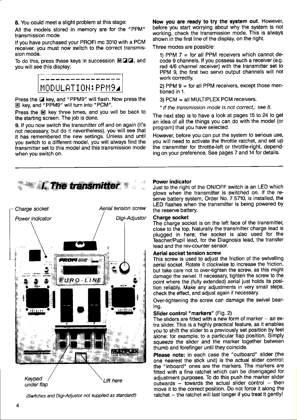
[::'"\'''*'
t\
LI\
|
'-'r
t,
Keypad
under
flap
(Switches
Digi-Adjustor
and
Aerial tension screw
here
Lift
not supplied
as standard!)
Power indicator
to the
Just
glows
serve
LED flashes
reserve battery
the
Charge socket
The Charge
close
plugged
Teabher/Pupil
lead and the
Aerial socket
This screw
aerial socket.
take care
but
damage
point
tion reliably.
check the
Over-tightening
Ing.
Slider
The sliders are
tra slider.
you
to shift the
älone:
squeeze
thumb
Please note:
one
"inboard"
the
fitted with a
adjustment
outwards
move it to the
ratchet - the
right of the ON/OFF
when the
battery system,
when the transmitter
socket
to the
where the
nearest the stick
top. Naturally
in here;
lead, for the
rev-counter
tension
is used
Rotate it clockwise
not to overtighten
the swivel.
(fully
Make any
effect, and
the screw
control
for example,
and
"markers"
fitted
is a highly
This
slider to a
the slider and
forefinger until
in each case
ones
fine
purposes.
-
towards
correct
ratchet
switch
transmitter
Order
is on the
the socket
sctew
to adjust
lf necessary
extended)
adjust again
with a new
to a
unit)
are the
ratchet which can
To do
the
position.
will last
is switched
No. 7 5710,
left face of
the transmitter
is also used
Diagnosis
sensor.
the friction
to
the
tighten
aerial
adjustments
necessary.
if
can damage
(Fig.
2)
form of
practical
previously
particular
the
they coincide.
actual slider
feature, as
marker together
"outboard"
the
is the actual
markers.
push
this
Do not force
longer if
LED which
is an
on. lf the
is installed,
is
being
increase the
screw as
in
set
flap
be disengaged
powered
the transmitter,
charge
lead, the transJer
of the swivelling
the screw
just
holds its
very small steps,
the swivel
marker - an ex-
postion
position.
slider control:
The markers
the marker slider
control
you
treat
lead
for
friction,
this might
it
enables
by
Simply
between
slider
-
it
along
gently!
it
re-
the
by
is
the
to the
posi-
bear-
feel
(the
are
for
then
the
Page 7
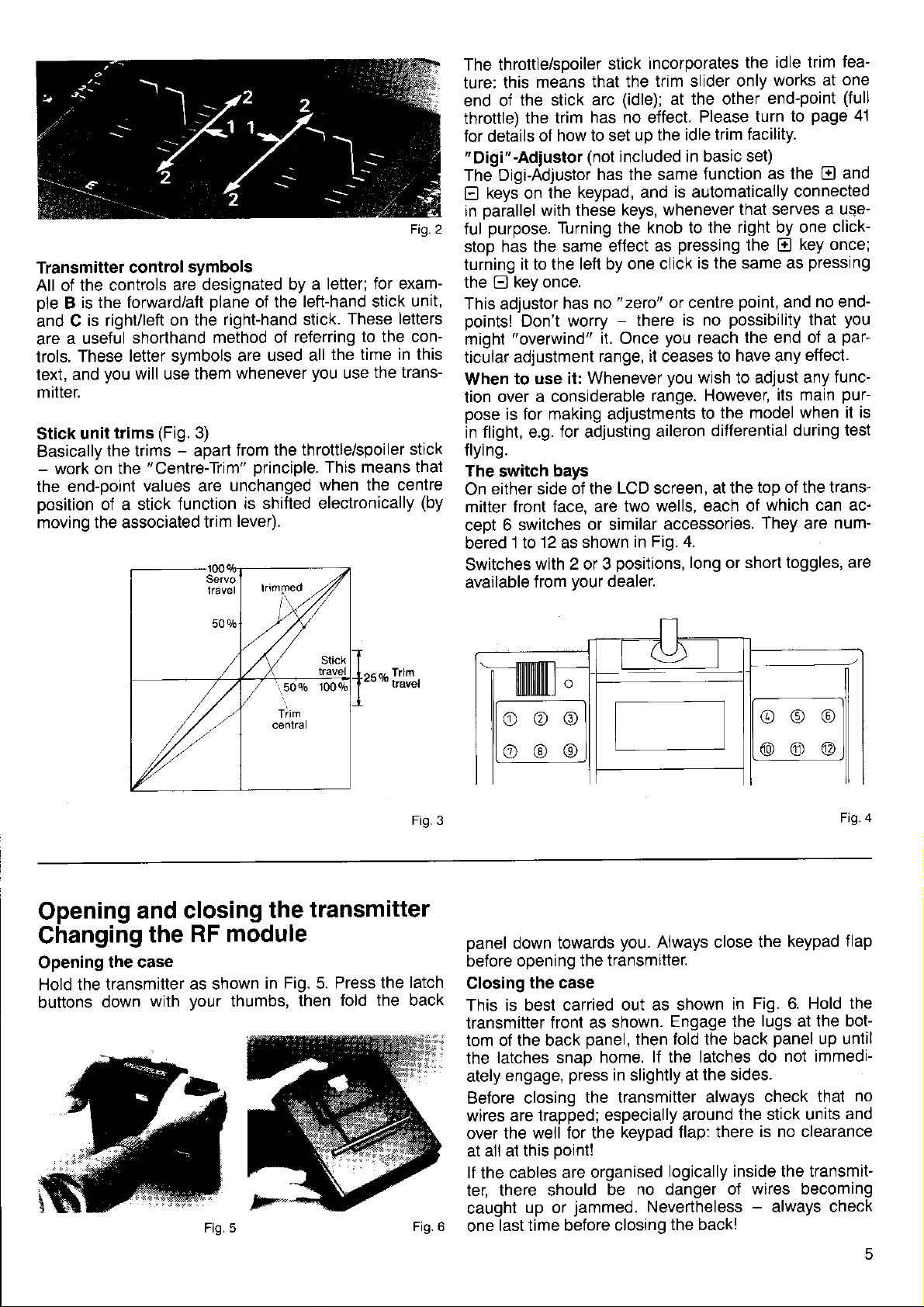
Transmitter
All of the controls
is the forward/att
ole B
and C
a useful
are
These
trols.
text, and
mitter.
unit
Stick
Basically
-
work on the
the end-point
position
moving the associated
control
is right/left
shorthand
letter symbols are
you
will use them
trims
the trims - apart
stick function
of a
symbols
are designated
on the
(Fig.
3)
"Centre-Trim"
values are
trim
letter; for exam-
piane
right-hand stick.
method ol
whenever
from
unchanged
lever).
by a
of the
principle.
is shifted electronically
left-hand stick
These letters
referring to the con-
used all
the throttle/spoiler
the time
you
use
This means that
when the centre
Fig. 2
unit,
in this
the trans-
stick
(by
The throttle/sooiler
ture: this
end of
throttle)
for details
"
Digi"-Adiustor
The Digi-Adjustor
keys on the
E
parallel
in
purpose.
ful
stop has
turning
the
This adjustor
points!
might
ticular
When
tion
pose
flight, e.g. for adjusting
in
flying.
The
On
mitter front face, are
cept 6 switches
bered
Switches
available
means
the stick
the trim
how to set up
of
with these
Turning the
the same effect
it to the left by one
key once.
E
Don't worry
"overwind"
adjustment
to use it:
over a considerable
for making adjustments
is
switch
either side
bays
12
1 to
with 2 or 3
from
stick
that the
arc
has no effect.
(not
has the same
keypad, and
has no
as shown
"zero"
-
il. Once
range, it ceases
Whenever
of the LCD screen,
or similar
positions,
your
dealer.
incorporates
trim slider only
(idle);
included
keys, whenever
there
two wells,
in
the other
at
Please
the idle trim
in basic set)
function
is automatically
knob to the
pressing
as
is the same as
click
or centre
is no
you
you
range. However,
aileron
accessories.
Fig. 4.
possibility
reach
to have any
wish to adjust any
the model
to
differential
at the
each of
long
or
the idle
turn to
tacility.
that serves a uQe-
right by one click-
the
point,
the end ot a
top of the trans'
short toggles,
trim fea-
works at
end-point
as the
connected
E
and
its main
during test
which can ac'
They
one
(full
page
and
El
key once;
pressing
no end-
you
that
par-
effect.
func-
pur-
when it is
num-
are
are
41
Opening
Ghanging
Opening
Hold the transmitter
buttons
and closing
RF module
the
the case
as shown
your
down
with
thumbs,
Fig. 5
transmitter
the
in
Fig.
Press the
5.
fold the back
then
Trim
o,{^
Fig.3
latch
Fig.6
ilililililtlil|
.
o@o
o@o
panel
down towards
before opening
Closing
This is best carried
transmitter
tom of the back
the
ately
Before closing
wires
over the
at
lf
the cables
ter, there should
caught
one
the case
latches snap
engage,
are trapped;
well tor the
all at this
up or
last time before
the transmitter.
front as shown.
panel,
home.
press
in slightly at
the transmitter
especially around
point!
are organised
be
jammed.
closing
@o@
@@@
you.
Always close the
out as shown
Engage the
then fold the back
lf
the
keypad flap: there
logically inside the transmit
no danger of
Nevertheless - always check
the back!
in
latches do
the sides.
always
the stick units
keypad
Fig. 6. Hold the
lugs
at
panel
not immedi-
check that
is no clearance
wires becoming
4
Ftg
flap
the bot-
up until
no
and
Page 8
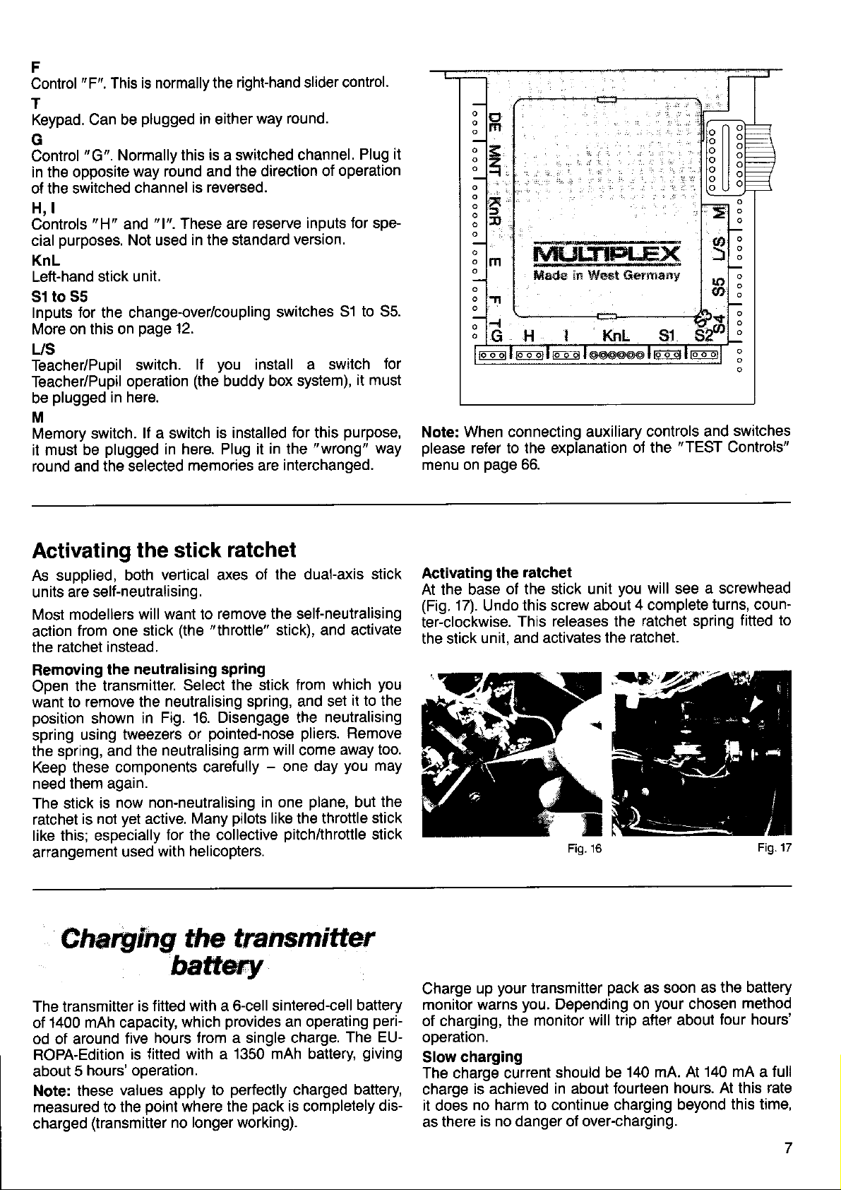
Changing the
Grasp the
it
oull
uo and
The crystal is
(Fig.
8). Pull out the crystal by its
plugging
correctly
Before
tag over to one side.
When
centre
plugging
relitting the module
of the
RF module;
module
out of its holder.
plugged
in a crystal make sure that both
in
the socket
unit,
the recessed
at
into the side of the
in
the module in
but
around
changing crystals
points (Fig.
plastic
module.
the
again,
not
do
the finger recess
bend the
press
7), then
RF module
When
tag.
pins
engage
plastic
down
in the
position.
This will help to ensure that
it is fitted
avoiding damage to the contacts.
Ftg.7
squarely,
thereby
in
the
panel
holder
receiver
(Fig.
Transmitter back
lnside
both sides there are holders for a spare
On
tals
formed
their correct
lnside the
a replacement fuse. Please note the specially
and
holder for
Don't lever them out - slide them!
double superhet
position
transmitter
Fuse
Take a
to
during
look
protect
rapid charging.
with the same
-
standard
2A may cause damage
than
Fig. 13. The basic
at
transmitter against excessive currents
the
type
commercial item). Charge currents
lf the fuse burns out, replace
(5
x 21mm,2 Ampere,
purpose
to the transmitter electron-
ics!
Cable compartment
The leads from
inside
the
To open the compartment
latches to one side
Pass the
wires from each connector
ment through the
through
ule.
dated
the openings on the side
Part of the
inside the compartment.
left at the switch
Always arrange
the cables
the stick units
the various switches are stowed away
(Fig.
compartment
cable
14).
push
and lift the cover off.
nearest opening. Lead them out again
"excess"
cable length can be accommo-
nearest the RF
Any spare cable
position.
the wires carefully and
forming a mass of unruly
or close to
the keypad cover well.
pair
of crys-
and
9).
of
crystals
the fuse is
it
quick-actjng
higher
one of the spring
into the comparl
mod-
is best
neatly, to
"spaghetti"
avoid
around
Outside
There is a well in the outside of the back
commodates
port
bar can be set
flush, at right-angles to
as a carrying
\
The connectors
Three
Starting
the
Control
sides
posed,
i.e.
stick units,
DE
Digi-Adjustor. lf
and
El
MNT MULTINAUT
KnR
Right-hand stick unit.
E
the transmitter aerial Ior transport. The sup-
Figs. 10
for the
"wrong"
the
positions:
to three ditferent
form
a back support, and upright
handle. Please refer to
Fig. 11
Fig. 13 Fig.
of the main electronics circuit
each fitted
from the
E
"E".
with
connectors
switches and so on. See
lefl,
these are:
you plug
f
unctions
(module
This is normally
in
this
will be reversed.
no longer available)
the left-hand slider control.
panel
which ac-
folded in
12.
to
Fil.12
Fig.
board
"peripherals",
Fig. 15.
are
way round,
14
14
ex-
6
Page 9
F
Control
T
Keypad.
G
Control
in the opposile
ol the switched
H, l
Controls
cial
KnL
Left-hand
51 to
Inputs for the change-over/coupling
More
US
Teacher/Pupil
Teacher/Pupil
be
M
Memory switch.
it must
round and
"F".
This
Can be
"G".
Normally this
purposes.
stick unit.
55
on this on
plugged
in here.
plugged
be
the selected
is normally the
plugged
way round and
channel
Not used
page
switch.
operation
lf a switch
in either
is
is reversed.
in the standard
12.
you
lf
(the
is installed
in here. Plug it
memories are interchanged.
right-hand slider control.
way round.
a switched
the direction of
buddy box system),
channel.
version.
switches
install a switch
for
in
the
Plug it
operation
51 to 55.
it must
purpose,
this
"wrong"
for
way
When connecting auxiliary
Note:
please
menu on
refer to the explanation
page
66.
controls and
of the
"TEST
switches
Controls"
Activating
As supplied, both
are self-neutralising.
units
Most modellers
action
the ratchet
Removing
Open
want to
position
spring
the spring, and
Keep these
need
The stick
ratchet
like this; especially
arrangement
trom one
the transmitter.
remove the
shown
using
them again.
is not
the stick
vertical axes
will want to
stick
instead.
neutralising spring
the
neutralising spring, and set
Fig. 16. Disengage the
in
tweezers or
the neutralising
components carefully
now non-neutralising
is
yet
active.
for the collective
with helicopters.
used
Charylng
ratchet
of the dual-axis
remove the self-neutralising
"throttle"
(the
Select
the stick from
pointed-nose
pilots
Many
the transm
stick), and activate
which
neutralising
pliers.
arm will come
-
one day
in one
plane,
like the throttle
pitch/throttle
itter
away too.
stick
you
it to the
Remove
you
may
the
but
stick
stick
ratchet
17).
Undo
the
of the stick unit
this screw about
This
and activates
Activating
At the base
(Fig.
ter-clockwise.
the stick unit,
you
releases the
the ratchet.
Fig. 16
will see
4 complete
ratchet spring
a screwhead
turns, coun'
fitted to
Fig.17
The transmitter
1400 mAh capacity,
of
od of around
ROPA-Edition
hours' operation.
5
about
Note: these
measured to lhe
charged
(transmiüer no longer working).
is fitted with a 6-cell sintered-cell
hours trom a single charge.
five
is {itted with a
values apply to
point
batt*y
which
where
provides
1350 mAh battery
perfectly
the
an operating
charged
pack
is completely
battery
perF
The EU-
giving
battery,
dis-
your
Charge
monitor warns
of charging,
operalron.
Slow
The charge current
charge
it does
as there
up
charging
is achieved in about
no harm to continue charging
is no danger ol over-charging.
transmitter
you.
Depending on
the monitor
should be
pack
as soon
your
will trip after about
140 mA. At
fourteen hours.
as the battery
chosen
140 mA a full
At this rate
beyond
method
tour hours'
this time,
Page 10
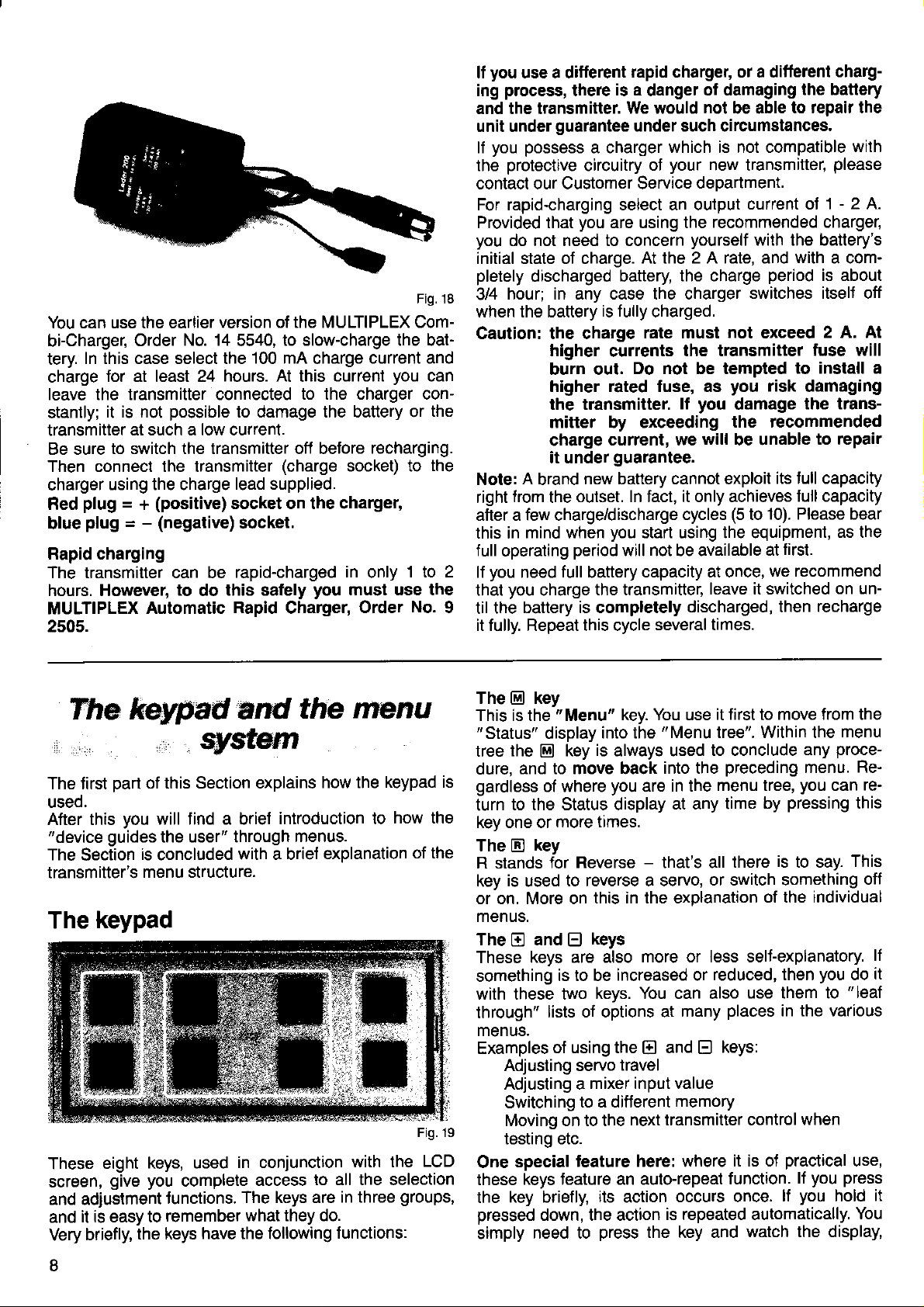
You can use the earlier
bi-Charger,
In this case select the
tery
charge
leave the transmitter connected
stantly;
transmitter
Be sure
Then connect the transmitter
charger
plug
Red
plug
blue
Rapid charging
The transmitter can be
hours. However,
MULTIPLEX
2505.
Order
for at least 24
it is not
to switch the transmitter off beJore
using the charge
=
possible
at such a low current.
(positive)
+
-
=
(negative)
Automatic
version of the MULTIPLEX Com-
No. 14
to
do
hours. At
lead supplied.
socket on the charger,
rapid-charged
this salely
Rapid
to slow-charge the bat-
5540,
100 mA
this
to the charger con-
to damage the battery or
(charge
socket.
Charger,
charge
you
current and
current
recharging.
socket) to
in
only
must use the
Order
Fig. 18
you
1to 2
No.
can
the
the
I
you
lf
use a ditferent
process,
ing
and the transmitter.
unit under
you possess
lf
protective
the
contact our Customer Service
For rapid-charging select an output
Provided that
you
do not need to concern
initial state of charge.
pletely
hour; in any case the charger
3/4
when the battery
Caution: the charge
Note: A brand
from
right
after a few charge/discharge
this in
full
operating
you
lf
need
you
that
til the
battery is completely
it fully. Repeat thrs cycle
there
guarantee
circuitry
you
discharged battery
higher
burn out.
higher rated fuse, as
the transmitter.
mitter by exceeding
charge
it under
new battery cannot exploit
outset. In fact, it only achieves
the
mind when
period
full
charge
rapid charger, or a difterent
is a
danger
We would
under such circumstances.
a charger
of
are using the
At
is fully
battery
the ilansmitter,
charged.
rate must
currents
Do not be tempted
current, we
guarantee.
you
start using the equipment,
will not be available
capacity at once,
several times.
of damaging
not
be able
which is not compatible
your
new transmitter,
deDartment.
recommended charger,
yourself
2 A rate, and
the
the charge
not
the transmitter
you
you
lf
cycles
damage
the recommended
will
be unable
(5
leave it switched
discharged, then
charg-
the battery
to repair the
with
please
-
current ol 1
with the battery's
with
period
switches itsel{ off
exceed
to install a
risk
its full capacity
full capacity
10). Please bear
to
first.
at
we recommend
2 A.
a com-
is about
2 A. At
fuse will
damaging
the trans-
to repair
as the
on un-
recharge
The
The tirst
useo.
After this
"device
The
Section
transmitter's
The
These
screen,
and adiustment
it is easy to
and
briefly,
Very
keypad aN
part
of this Section explains
you
will find a brief
guides
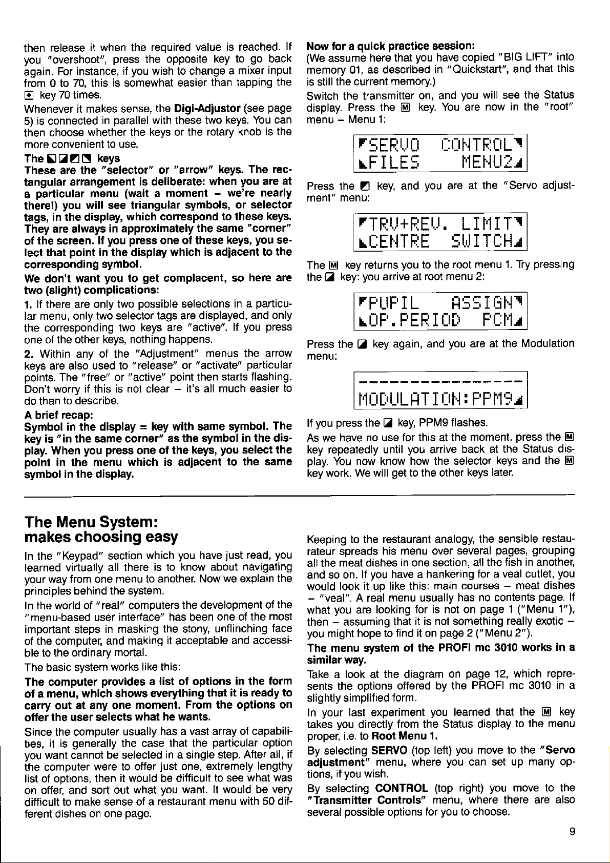
keypad
eight
give you
the user" through
is
concluded
menu structure.
keys, used
tunctions.
remember
the keys
qy$tgfi
introduction to
menus.
with a brief
in conjunction
complete
have the following
access
The keys are
what they do.
the
menu
how the
explanation
to all the selection
functions:
keypad is
how the
with the
in three
of the
Fig. 19
LCD
groups,
The
This is the
tree
dure,
gardless
turn
key one or
The
R stands
key
or on. More on
menus.
The E and
These
something
with these two
through"
menus.
Examples
One
these
the
pressed
simply
key
El
"Menu"
display
the m key
and to move back
of where
to the Status display
key
tr
is
used
keys are also
lists of options at
Adjusting servo
Adjusting a
Switching
Moving on to the
testing etc.
special
keys Jeature an auto-repeat
key briefly,
down, the action
need to
is
more times.
for Reverse - that's all
to reverse a servo,
this in the explanation
keys
El
is to be
keys. You can also
of using the
mixer input value
to a different
teature here: where
its
press
key. You use
into the
always used
you
"Menu
into the
are
more or less sellexplanatory
increased or
and
E)
travel
next transmitter control
action
is repeated automatically.
the key and
it first
tree". Within the
to conclude
preceding
menu tree,
in the
at any time
or switch something
reduced, then
places
many
keys:
E
memory
function.
occurs once.
move from the
to
pressing
by
is
there
of the individual
use them to
in the various
it is of
practical
lf
watch the display,
menu
proce-
any
menu.
you
can
to say.
you
when
press
you
lf
you
hold
Re-
re-
this
This
off
lf
it
do
"leaf
use,
it
You
I
Page 11
release
then
"overshoot",
you
again.
from 0 to
E
Whenever
5)
then
more convenient
The
These
tangular
a
there!)
tags,
They are always
of
lect that
corresponding
We don't
two
1,
lar menu, only
the
one
2. Within any
keys are also
points.
Don't
do than
A
Symbol
key
play.
point
symbol
For
key 70 times.
is
connected
choose
IZZN
particular
in the display,
the screen.
(slight)
lf there are only
corresponding
of the other
worry if this is not clear
briet
"in
is
When
in the menu
it when the
instance,
70, this
it makes sense,
in
whether the keys or the
to use.
keys
are the
arrangement
you
point
The
to describe.
recap:
in the display
in the display.
"selector"
menu
will see triangular
in approximately
you
It
in the
symbol.
you
want
complications:
two selector tags are
keys, nothing
of the
used to
"
trce" or
the same corner'r
you press
required value
press
you
if
is
somewhat
parallel
(wait
which correspond
press
display
to
two
two keys are
"release"
"active"
which is adiacent
opposite
the
wish to change a
easier
the Digi-Adiustor
with these two
"afto^ "
or
is deliberate:
a moment
symbols, or
the
one ol these
which is
get
complacent, so
possible
"Adjustment"
=
one
selections
"active".
happens.
"activate"
or
point
-
it's all much easier
key with same symbol.
as the symbol
ot the
keys,
is reached.
key to
than tapping
rotary knob
keys. The
when
-
same
adiacent
displayed, and
menus the
then
go
mixer
(see
keys. You can
is the
you
are
we're nearly
selector
to these
"
cornet"
you
keys,
to the
here are
particu-
in a
press
you
lf
arrow
particular
starts flashing.
in the dis-
you
select the
to the same
lf
back
input
the
page
rec-
at
keys.
se-
only
to
The
Now
We
memory 01,
is still
Switch
display.
menu
a
assume
the current
-
here that
as described
the transmitter
Press the
Menu 1:
quick practice
for
r
PROFI mc
3O1O
EURO-LINE
menu
Sheet
rTHLI+FlEtJ.
structure
1
SERVO
LIlllTr
rl:El.lTFiE 5lrllTt-Hr
MEMORY
7L:tlPV
r5H I FT
Eh FIE5TFI FPI'I:T
t. 5r:rr.rllllllErEr : IEl
Menu 1
r_;EEtJr_r
r-:r:rt.lTF:üLt
rF I LE!; l'lEHUfu
Htll,lEt
t-:H1"..
TE I l'1.i
Menu 2
TFUFIL
rr:F . F'EF:I
II5!;IEI.]t
tltt
Fl:l'L
BB File number'1 ...30, Fx
F I E5Tll File name, I characters
PFll9 Transmissionmode
l. SBU Battery voltage,
llllll
tlB | 2B Operating
Battery voltage, bar
rtlül'lEr I
digital
period
graph,
in
hours rminutes
CONT ROL
-::trl.
6 blocks
!:ET UF'\
TE!:Tr
--
FLTFIL r4ütiE
: IJFF
15
Pupil mode ON means:
Trim on the
is not active
pupil
transmitter
r]rlHTE:lrL5
I
FIUIIDEE
Select control
and assign
Select MEMORY at bottom
which copes
For the moment, the bottom
thing else
2. You might
"contd.".
In Root Menu 2 things continue
function
with everything to do with memories.
which the transmitter
like
rFt_tF
LIJF. FEF;
you get
On the
left
--
r
to think
I L
I Lltr F
to the
pupil
--t:tF
Reset operating
r +FII
.'+FlU[t[tE /'+ELEIJt]
Release functions,
to be controlled by the
left, and
right
of this option as
in
H:;5I
menu and the operating
ER. FEFr I
t--t['--
F:E5ET: Erlr l€, r
period
to 00:00 Select
ASS/GN
Tt.UHTFIUL
rTEFtlH
LEE
option
has
to
the same
J+5F'U
pupil
you
find a
hides every-
offer, via Menu
menu
"more"
way:
I L
rif.lr
tll'p
l'1ltI:,LlLET I
modulationl
PPM 7
PPM 9
PCM
t:tl.,l:
FF tl'i..
!;EF:l..lr.lr
l-l5F:-l'l
rLt!:F:-l'1I
rlHF,1! .". /
Define user mixers:
period
cause
sidedown!
known as a
or
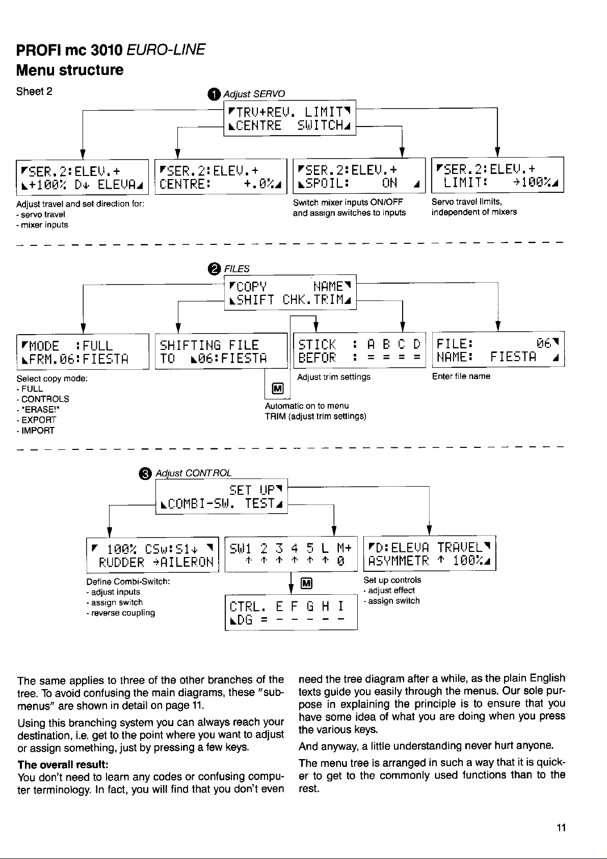
menu structure. Have a look at the diagram above.
will
hidden
This is intended to show that there are
which are accessible from the
they are
change), and
I lir
i:+T+E:j
li 1
select USR-MIX 1,2,3
select input INP 1,
assign function
2,
3,4
timer; on the righl to
Automatic
ASSIGN SERVO
H!;51rjH SEELJ|| 1
Select servo
and assign
on to
"Assign"
of the similarity to a tree - albeit one
-
this type of menu arrangement is otten
"menu
for example, that there are
see,
behind
tree", or
the " Files" menu.
-
"Files"
"Copy", "Shift"
"Chk.Trim"
(switch
(check,
Tü I.IILEF:UH r
lunction
menu
and
more technically, as a
four more menus
four
menu; in this
models),
match).
"Name"
"PCM".
growing
"dead
ends"
(enter,
I
Be-
up-
You
case
10
Page 13
PROFIMC
3O1O
EURO-LINE
Menu
r!:EE.l:
r+lBtlil
Adjust
rl{u[:'E
\FFll'.|,
Select
-
FULL
-
CONTROLS
.ERASE!'
.
EXPORT
-
IMPORT
structure
ELE\.r.
F+
travel and set direction
:
r:1b:
mod6:
copy
+
ELEl..lF/
FULL
FIE5TH
15EFl.
ELEU.
i:
I:EHTEE:
for:
@
5HIFTlHIJ
Tlt rr:rh:FIESTH
rTEr.r+FELr.
rr-:El.lTEE
+
+.
ü:1.I
LII'lIT!
5til I TtlHr
7::EF:.
r:;Fl.t
Switch
and assign
ntes
rl:ilF'i
r:;H I FT
FILE
Aulomalic on to
TRIM
HF,tl'lEr
t_:H1.,.
TF:l l'1r
5T I
EEFI:IF:
Adjust trim
(adjusl
trim setlings)
l: ELELT,
I L:
inputs
mixer
switches
ON/OFF
r::ti
settangs
menu
+
l:lt{
to inputs
/
F I LE:
HFII.IE:
Enter
file name
ELELI.
+
+
1LlE:.:/
EE,I
FIE5TF
/
Define
-
adjust
-
assign switch
-
reverse couplrng
The same
tree.
menus" are
Using
destination,
or assign
The overall
You don't
terminology.
ter
applies
To avoid confusing
shown
this branching
i.e.
something,
result:
need to learn any
r
rjrJ:,j rl5L,r:
l
F:LITlIIEE
Combi-Switch:
inputs
to three
the
in
detail
system
to the
just
you
point
by
get
In fact,
ROL
CONT
5ET
-5t'l.
rt_:Ltl'1E
I
51+
+FI
I LEEI.]H
r
TE5Tr
ITFIL.
LLT|I
of the other branches
main diagrams,
page
on
you
pressing
codes or
will
11.
can always
where
you
tew keys.
a
conJusing compu-
find
that
want to adjust
you
of
"sub-
these
reach
don't even
I]FI
F F ,-. rr t
LFtlnl
-
the
need the
texts
pose
your
have some
the various
And anyway,
The menu tree
er to
rest.
rII:
ELEIJH
H!;Vl'ltlETF;
up controls
Set
-
adjust etfect
-
assign
tree diagram
you
guide
in explaining
get
easily
idea of
what
keys.
a little understanding
is arranged
to the commonly
TFIHUELT
+
switch
after a
through the
principle
the
you
are
in
used
FJrili:^r
1
while, as the
plain
menus. Our sole
is to ensure
doing when
never hurt anyone.
a way that
such
Junctions
English
pur-
you
that
you press
quick-
it is
than to the
'11
Page 14
t.r
,
This
section
and
cal,
However, sooner or
of this information,
switches or
As we have already seen on
connectors are described,
types of connector.
First there are the connectors
only: Digi-Adjustor
(M).
There
unit must be connected
each
Next comes the
These are
Here a brief explanation
C, D are
gether
(right-hand
connected
The remaining inputs are
is where
switches"
What are
Well, in coarse terms, these
ments" on
something on
units,
which
So
switches?
These switches
something
tween
activate
f lap/elevator
An
The switch
does
and
as it is connected
the sliders, and
you
what are change-over switches
different
"extra"
not fit into our
should
is necessarily somewhat
you
can skip
other exDansion units.
is not much to say about these sockets
group
connectons for the transmitter
not
shown
"KnU'
as
stick = C,
to the correct sockets
"change-over
are connected.
transmitter controls?
your
transmitter,
your
use to
coupled controls
release the aero-tow mechanism.
are usually used
on the model, but,
pre-set
coupling switch).
for the expert:
"Sl"
really be included as a
it for the moment
you
later
particularly
(DE),
of
individually; they are
(left-hand
D). The
model. They
values
is a special-purpose
neat
to input
will need to absorb
page
there are several diflerent
which have one
Keypad
in the correct
"letter
is necessary: the
stick
stick
marked
switches"
are all the
which
also, for example,
for example, to
(such
(e.9.
scheme.
"l".
However,
'
dry and theoreti-
you
il
when installing auxiliary
where the
Z
and Memory Switch
ff)
place.
inputs": A to
inputs A, B,
grouped
=
A, B) and
units must also
(KnL
and KnR).
to S5 and US.
51
and
"movable
you
use
include the 'wo stick
and coupling
not to actually
Dual Rates) or
as
Combi-Switch,
feature which
is
lt
a 3-stage
"transmitter
it
can
wish.
some
internal
purpose
-
l.
controls.
to-
"KnR"
be
This
"coupling
ele-
to operate
the switch
move
switch be-
to
or a
switch,
control",
be used
to one of the change€ver
in a similar
switches;
control.
An explanation
confuse
Section
Now we come
ble source of
According
ther a
switch,
transmitter.
Change-over
2-core connecting
not be used
Switches
ther a
switch
switch
Why?
inpüt
input sees a switch
the
be set to
And one more
In line with
ble to connect
to inouts
be a useful
can
many switched
On the
further Dots
Most users
these
cursion
you
give
new system.
What this all
When
always
tions.
When
pling
L/S.
When f itting auxiliary
the number
way
especially
matters at this
entitled
confusion.
to what we
transmitter control
depending on
But this
switches and
for this
which act
2-core or a 3-core
(2-position)
it must be 3-core.
When
"sees"
features. Our
switches,
you plug
whatever
its
end-ooint
what we have
E and F
other hand
instead of switches.
of the
into the
idea of the flexibility
an
means in
you
assign
yoursell
find
you
are
of wires
in combination
of these
"
For experts".
to
note
switches
feature for special
channels.
"
assigning
you
further difterence,
one
have
where
is only
lead. A switch
ourpose.
as transmitter
the lead
in a switch,
the unit
values.
instead of the standard
inputs G,
PROFI mc 3010
intention
realm of the unused
or adiust
dealing
will be dealing
switches
in the cable.
with a transmitter
special
point.
just
or a change-over
partly
lead.
as a crude
just
(preferably
practice:
transmitter
change-over
features
Please see
said, a switch
it is
connected
true:
coupling
is 2-core.
is
said,
H, I can also be
presenting
in
with the
you
switches
with a 3-core
controls
For a simple ON/OFF
the transmitter
potentiometer
a
as
pot,
which can only
perfectly
it is
3-position
models
hardly ever need
will
features" is
versatility of
and
controls,
"letter"
switches
with 51
must bear
or coupling
would only
page
and a
may have ei-
For a 3-stage
sliders.
which
this brieJ ex-
in the
69
possi-
can be
or coupling
inside the
lead can-
switches)
used with
abbrevia-
to S5 and
ei-
have a
control
So
possi-
This
require
just
to
your
you
will
or cou'
in mind
The
or
(Here
LIFT" into
OJ course,
every
When
will appear
of the
trolling
12
"Operations"
"Status"
again
memory 01, as described
and that
you
what
model memory.)
other
you
switch
on the LCD screen.
important things
most
your
display
we will assume that
not switched to a different
have
we are
the transmitter
model:
going
you
you
have copied
under
say next applies
to
on, the Status
provides
lt
need to
"Quickstart"
memory.
a summary
know
"BlG
to
display
lor
con-
rtrl
i
The top line:
=
number
Ol
the memory
operated
that
BIG
easier
PPM 9
(modulation). Also the same
the set.
the system.
you
last operated.
LIFT
than
=
EITiLIFT
. ErSrtllllllr:rri
of the
(or
=
Name of the
remembering
Transmitter's current
"current"
"list")
which
This usually
a number,
FFI'l'1
:
memory.
was in use
means:
model
as the
in English.
isn't it?
transmission
last time
trr
This is always
model
That's
mode
you
you
used
last time
the
Page 15
The second
line:
After the bar
display:
r:r.
i4r.IllIIII
=
transmitter
Y
8.24
very accurate,
glance
first
at
mediately after
At 6.9 Volts
V.
8.4
tery should
to the digital
Next
"boxes".
age display;
isnot
voltage.
tery
using
are
gradually
are
comes
lhe
and
play
is not as accurate
it
but
be
This is an analogue
it
so accurate.
The battery
the transmitter,
erased
shorter.
inherently approximate
you
gives
battery
unfortunately
but
-
a drawback
full
a
charge
the battery
recharged.
display
is
easier
Consider
Because
a useful
How to use
the operating
There
to
display)
oeriod timer
is not much to say
it is reset
it
to
press
menu:
period
zero. To do this
f]
E Z
--ÜFEFI.
EE:;ET:
Press the
00:00,
Return to
The operating
hours :
There
timer.
the
corded
and
minutes.
is nothing
When the
last displayed
value
key; the
Z
you
the Status display
done.
are
period
next time
display
else to
transmitter
time
vohage. The digital
not
of all digital
voltage
the
monitor trips, and
"bar"
is a
to understand
it as a rough
discharges steadily
and at the
from right to
of manujacturing
reliable as the digital
and
idea ol how things
consisting
version
same time
left; i.e. the bar
nature of the bar,
to assimilate
easy
displays.
is
about
ol the digital
glance,
at a
indicator of bat-
are
timer
about this
. You will now be at
FEFI
value displayed
with
worry about concerning
and starts
you
switch
timer; all
(starting
trom the Status
I LItI--
Et:l:
is in the form
is switched
ltit r
@ El El
again
on.
will
.
the operating
off,
from the
is
value
lm-
-
8.2
the bat'
to 6
of up
volt
it
but
you
while
the boxes
be-
tolerances,
the disdisplay,
going.
you
can do
change
it records
to
this
re-
very useful
A
The operating
At any
in use since
been
(you
zero
on this
The timer
you
often
period
ing
continues
and
practice
In
lows: set it to
The display
When should
The timer can
starts again
to measure
might be
flying time
It makes
you give
time
transmitter's
around
curate
consider
only
batteries
result
can
is to carry out
your
long
leature:
you
time
can do
page
for more details).
is cumulative,
switch
timer
the best
zero every time
shows
from
the
enough
per
most sense
the
operating
four hours, so
idea of
this value as
and
in variations of up
own transmitter
rlrl:2+
period
when
I reset the display?
count uo to
season.
how much
in the transmitter's
a
display
how long the
see
can
the last
that at any
the transmitter
stops counting
you
way of
hours :
zero. That's by
lifetime of the
for
transmitter battery
practical
time the timer
time - see
makes no difference
and it
on and
when
switch
"occasional
to reset
period
the display
on again.
managing the
you
recharge
minutes.
99 hours 59
no means
transmitter, although
flyers"
the timer
lrom a full charge
gives you
guide.
a
to +/-
you
current
lasts.
longer
experiment
actually
Slight
transmitter
reset to
was
the next section
ofl; the operat-
you
switch
timer is as
the battery
minutes, then
long enough
to count their
to zero every
lull charge.
a
quite
fly. But
can
differences
Your
20010.
to determine
please
consumption
best
has
how
off,
foF
it
it
The
is
an ac-
in
bet
how
How
sion
The transmitter
(e.9.
You
type
This is
From
"PPM/PCM"
You will see
to switch
modes
"UNl
have to set
receiver
of
how
the Status
can be used
9") and
you
you
do
display.
this:
l'lUttLlLHT
transmis-
between
the
PPM7, PPM9 and
with both
with PCM units
the transmission
wish to use.
it:
Display
press
(e.9.
EIZZ
I ül'lr
PPM
'PCM
mode to
to arrive at
FFI'1fu
PCM
receivers
DS').
match the
the
Press
start
Press the
versa).
change
Press
It is only
use a
4/6 channel
this type
the servos
rectlv
the
E
to flash.
E
That's all there
from PPM
three
El
necessary
receiver
receivers buill
of receiver
attached
"PPM7", 'PPMg"
key.
PPM will change
key.
is to it. Use
7 to PPM 9 and back.
times to
which cannot
get
back
to switch to
decode 9 channels
in 1979).
with the
to outputs
transmitter set
"PCM")
(or
PCM
to
the E or
to the Status
you
PPM 7
1 + 2
if
you
lf
attempt to
will not work cor-
will
(or
vice
key to
El
Display.
wish to
(e.9.
use
to PPM I,
13
Page 16
("ready
made lists')
In the transmitter's standard
15
No.
grams).
centage of the
tising
You
to the appropriate
Before
the direction of servo
page
You may like to use these examples as
for
"original",
scribed
copy.
The following example
as standard:
Memory
"FIESTA'
Memory
"SALTO'
Memory No. 8:
'F3B"
(Crow
Memory No. 9:
"CORTINI('
Memory No. 10:
"BlG
Memory
"RCl/F3A'
contain
These example
modellers.
can
you
28.
your
on
-
a
system)
LIFT' - a
"ready
models which
use any of these example lists
your
fly
own lists.
first copy it into an empty
page
No.
6:
-
typical simple
a
No. 7:
-
typical
a
typical FSB class
-
a typical tailless
typical simple
No. 11:
-
a typical
programmed"
memory as described on
model,
rotation,
you
lf
41)
and then
glider
powered
form, memories
model lists
programs
you
do
lists are available
glider
with
glider
embrace a
are actually
may
that is described on
and
not want to change
make modifications to the
V{ail
and
with
glider
powered
aerobatic
No. 6 to
(or pro-
per-
high
flown by
by switching
iust
well have to alter
the starting
memory
"flaperons"
"aileron
model
model
prac-
page
43.
point
the
(as
de-
brakes"
(roll)
Interchanging aileron
1. Select the
From the
r
ASSIGN CONTROLS
Status
fi
Display
r::r:rl.lTF:t:tl::
and
press
@ Z N Z
L FII LEE:I:II..I
Note: if
trol,
Z
2. Assign control
lows:
you
you
must first select Control
key then
oress ! EIE
r
H
worked
last
or E until A appears
El
A to the rudder
. Result:
different transmitter con-
on a
t_:ilt,lTF;uL:;
r FiUtitiEFi
Assign
3.
oress Z E E,
r
control
t:: t::t:tl..lTFtt_tLl
L FII LEF:LIH
4. Return to the Status
it finished.
Interchanging throttle/spoiler
elevator
1.
EIZNZ,
(pitch-axis):
Move to the
as described
r
t
t::üt..lTFlr.rL:,
E
ELEI.JI]TÜFJ
C to the ailerons
then
SIEIE
"ASSIGN
. Result:
Display:
CONTROLS"
above.
rudder
A. To do this
press
(collective
(tail
menu
.
resp. R0LL
in the display.
(or
(or
rotor), as fol-
tail
resp.
roll), as
resp. R|ILL
E E] E E]
resp. P I TrlH-FN
rotor):
press
the
TF I LRÜT
follows:
. That's
pitch)
menu with
and
I5
Memory
"MIRAGE"
Memory
"
HELI BOY" - a typical
"Schlueter"
Memory
"
RANGER"
"Heim"
Memory
'8K117'
head - head
In all the examples
is set up
Rudder
right-hand
Throttle
roll)
you
lf
structions
14
No. 12:
-
a typical delta
No. 13:
rotor head
No. 14:
-
a typical helicopter
head
rotor
No. 15:
-
a typical
linkage using virtual swashplate
as tollows:
(or
tail rotor) and elevator
stick.
(or
spoilers or collective
on the
left-hand
ditterent transminer
use a
on how to change
helicopter with
it is
stick.
model
helicopter with
with
"120
assumed
that the
(pitch-axis)
pitch)
mode,
the settings:
degree"
and aileron
here are briet
rotor
transmitter
on the
(or
you
il
Note:
you
trol,
key then E or
Z
2. Assign control B to
press
lows:
(or
PITCH-AXIS) appears.
r
t
Assign control
3.
as follows:
THROT/SPOIL
r
last worked
must first select Control
!,
E [ÜHTRÜ15
ELEUIlTÜE
press
rlüt.tTFiü15
ti
I THEITTLE
4. Return to the Status
times.
in-
procedure
The
described
in detail on
on a different transmitter
B.
until B appears
E
the elevator
then E or
and
D to throttle/spoiler
then
Z,
(or
COLL.
lor assigning
page
E
Result:
SIEE,
PITCH) appears.
Display by
the transmiüer controls
25.
To
do
in the display.
(pitch-axis),
repeatedly until
resp. P I TrlH-HH
(collective
then
or 5PU I Lt t{
resp.
pressing
press
this
or
El
Result:
rl0LL.
as
pitch),
E
@
con-
the
lol-
ELEV
I5
until
TllH
P I
four
is
Page 17
Example:
"FIESTA'
The
The ailerons are
cal differential).
left-hand stick.
coupling,
"FIESTA"
is
an
controlled by
The
"Combi-Switch"
radio-controlled
or
example of a
a single servo
airbrakes
are operated
supported.
towhook, if
simple model
(mechani-
with the
An aero-tow
fitted, is oper-
glider.
ated by
vide
tended.
standard,
the
a switched channel.
pitch
However, the mixing
and the user
feature.
mixer is featured to
A
trim compensation
when airbrakes are
input
has to set the
Memory No.: 6
pro-
ex-
is
to zero as
set
value if he needs
Summary:
Channel
controls
Servo
No
Function
inp.
1st
2nd inp.
Note: the
Switches:
"FLAP"
"SPOILER"
the
55 = Combi-Switch
Adiustments:
Possible
moditications: Combi-Switch
A B
Aileron Spoiler
I
AILERON
input of the
"ELEVATOR"
input can be set
Combi-Switch:
Aileron
All servos: travel
Airbrake ooeration
SPOILER
to any value by the
--
1000/0,
centre
C
D
Rudder i Elevator
SPOILER
RUDDER
mixer must be set to
0;
user.
rudder, following rate
1000/0.
00/0.
rudder - aileron, switched
via
instead of stick
slider
TOWHOOK
off
E
F G
Aero-tow
Page 18
Example:
"Salto"
The
inboard end of each
the
spoilers,
landing
the
servos,
up as
direction
with
"flaperons",
"SALTO"
is an example
which are used to
approach.
"electronic"
to act as
of a model
wing are
The ailerons are
differential.
i.e. they can be
camber-changing
2 rotating trailing edge
lose height and
operated by two
They are also set
moved in the same
f laps. As
with a V{ail.
to control
flaperons
At
which do
dynamic
small,
improve
can be switched
flaps and the spoilers
Drovide
not reach to
disadvantages,
and they
manoeuvrability.
automatic
the wing
the
should only be
off by
pitch
means of
are mixed
trim compensation.
root have
"flap
For this
Memory No.:
inherent
input" should be
for aerobatics to
used
reason the flap
the switch 53.
with the elevator,
7
aero-
kept
input
The
to
Summary:
Channel
controls
Servo
Function
1st inp.
rp.
lthi'p'
to
zr.ro
rp
sro
S1, 52
when
for the
modifications:
I
f
f
Switches:
Note:
Possible
No
FLAPERON
Dual Rates
for
adjusting
moment
the
Aileron
Flaperon
AILERON
on AILERON,
mixing inputs
Control
Use
of the
of Combi-Switch
Spoiler
Vtail
V-TAIL+
be very useJul
it can
FLAP input
V-TAIL+
ELEVATOR;
via stick
(controlled
53 switches
to switch
instead
via 55).
Elevator
Spoiler
SPOILER
the tlap input
off any
of slider
Flaperon
FLAPERON
AILERON
FLAP
to the ailerons
mixing
inputs
Aero-tow
Towhook
TOWHOOK
which are not needed
l
Page 19
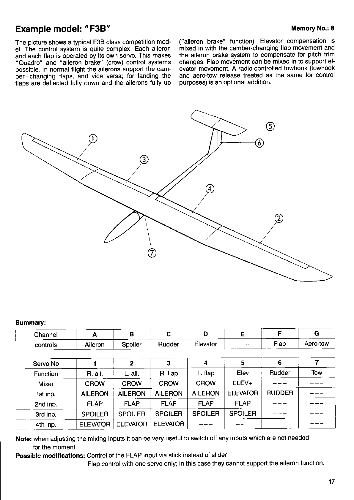
Example
model:
'FgB"
Memory
No.: I
picture
The
The control system
el.
each
and
"Quadro"
possible.
ber-changing
flaps are def
shows a typical
flap is operated by
"aileron
and
normal tlight the ailerons
In
flaps, and
lected f ully down
F3B class
quite
is
complex.
its own servo.
brake"
(crow)
vice versa; for
and the ailerons
competition
mod-
Each aileron
This makes
control systems
support the
cam-
landing the
Jully up
("aileron
brake"
mixed in with the
the aileron
changes.
evator
aero{ow
and
purposes)
brake system
movement can be
Flap
movement.
release treated as
is
optional addition.
an
function).
camber-changing
Elevator compensation
flap
to compensate
mixed in to support
A radio-controlled
towhook
the same
is
movement and
pitch
for
trim
eF
(towhook
for control
Summary:
Channel
Servo
Function
1st inp.
inp.
2nd
inp. SPOILER
3rd
4th inp.
when adjusting the
Note:
tor the moment
Possible
modifications:
No
Spoiler
r7z
L. ail.
CROW
nrr-enoru
FLAP
ELEVATOR ELEVATOR
mixing inputs
Control
Flap control with one
CROW
I nrLenor.r
SPOILER
it can be
of the FLAP
ELEVATOR
very
input via stick
servo only;
flap
R.
CROW
AILERON
SPOILER
useful
in this case they cannot support
Elevator
L. flap
CROW
AILERON ELEVATOR
FLAP
SPOILER
to switch off any
instead of slider
Elev
ELEV+
FLAP
SPOILER
inputs
Rudder
RUDDER
which are
the aileron
Aero-tow
not needed
function.
17
Page 20
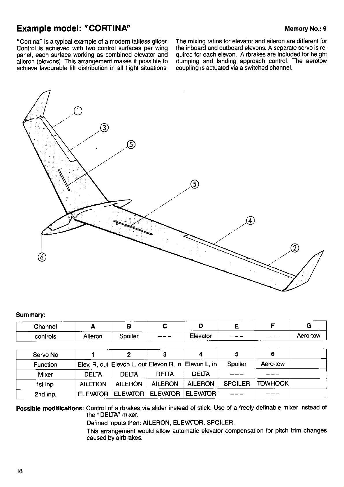
Example
"Cortina"
Control
panel,
aileron
achieve
each surtace working as combined elevator
model:
is a typical example
is
achieved
(elevons).
tavourable lift distribution in all flight situations.
"CORTINA"
of a modern tailless
with two control surfaces
This
arrangement
makes it
glider.
per
wing
and
possible
to
Memory
The mixing ratios for elevator and aileron
the inboard and outboard elevons. A seoarate
quired
dumping and
coupling
for
each elevon.
Airbrakes are included
landing approach control.
is actuated via a switched channel.
are different for
servo is re-
The
No.:
9
for height
aerotow
Summary:
Channel
controls
Servo
No 1
Function
Mixer
1st inp. AILERON
2nd inp.
Possible modifications:
18
Aileron Spoiler
Elev. R, out Elevon
DELTA DELTA
ELEVATORELEVA'TOR
A B c
2 3
L, oul Elevon R,
AILERON
AILERON AILERON SPOILER
ELEVATOR
Control of airbrakes
"
DELTA' mixer.
the
Defined
inputs then:
This arrangement
via slider
AILERON, ELEVATOR, SPOILER.
would allow automatic
caused bv airbrakes.
D
Elevator
4
in Elevon L, in Spoiler
DELTA
DELTA
ELEVATOR
instead of stick. Use
E
5 6
F G
Aero-tow
TOWHOOK
oJ a lreely definable
elevator compensation
tor
Aero-tow
mixer instead of
pitch
trim changes
Page 21

Example
"Big
The
Ailerons
model:
Litt"
landing
and
"BlG
represents
a simple
flaps are
LIFT"
powered
in addition
titted
model.
to the
standard
via the switched
controls.
channel.
An aero-tow
release
Memory
can be
operated
No. 10
Summary:
Adiustments:
-
Possible
modifications:
1
AILERON
Transmitter
Transmitter
Transmitter control
Combi-Switch:
All servos:
control
control
Aileron
1000/0, centre
travel
Combi-Switch
2
THROTTLE
Rate on aileron,
option:
option: throttle
option:
Dual
flap travel:
---
rudder,
rudder
00/0
-
3
RUDDER
trim:
idle
Oo/o,10oo/o
following rate
aileron,
]ELEVATOR
-30o/o
or switched
-------_
elevator,
1000/0
ofl
5
FLAP
ss-
Combi-Sw
rudder:600/o
6
AERO.TOW
19
Page 22
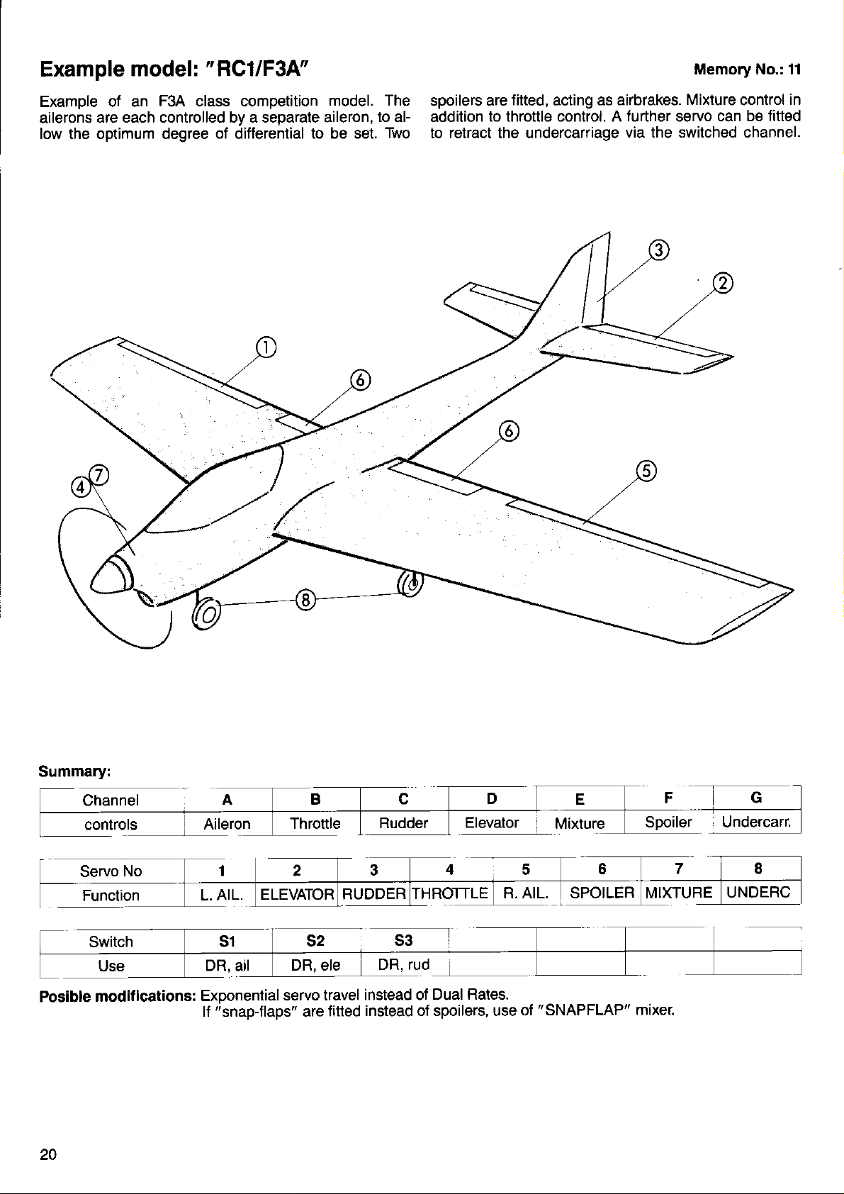
Example
model:
"RC1/F34"
Memory No.: 11
Examole of an
ailerons
low the optimum degree
are each controlled by a separate aileron,
F3A class comoetition
of
differential
model. The
to aF
to be set.
Two
spoilers are
addition
to retract the undercarriage
fitted,
acting
to throttle control. A further servo can
as airbrakes.
via the switched channel.
Mixture
control
in
be titted
Summary:
Channel
controls
Servo
Function
Posible
20
modifications:
No
L. AIL.
Exponential
"snapjlaps"
lf
servo travel
Throttle
titted
are
RUDDER
instead of
instead oJ spoilers, use
ROTTLE
Dual Rates.
Spoiler Undercarr.
R. AIL. MIXTURE
"SNAPFLAP"
of
mixer.
UNDERC
Page 23
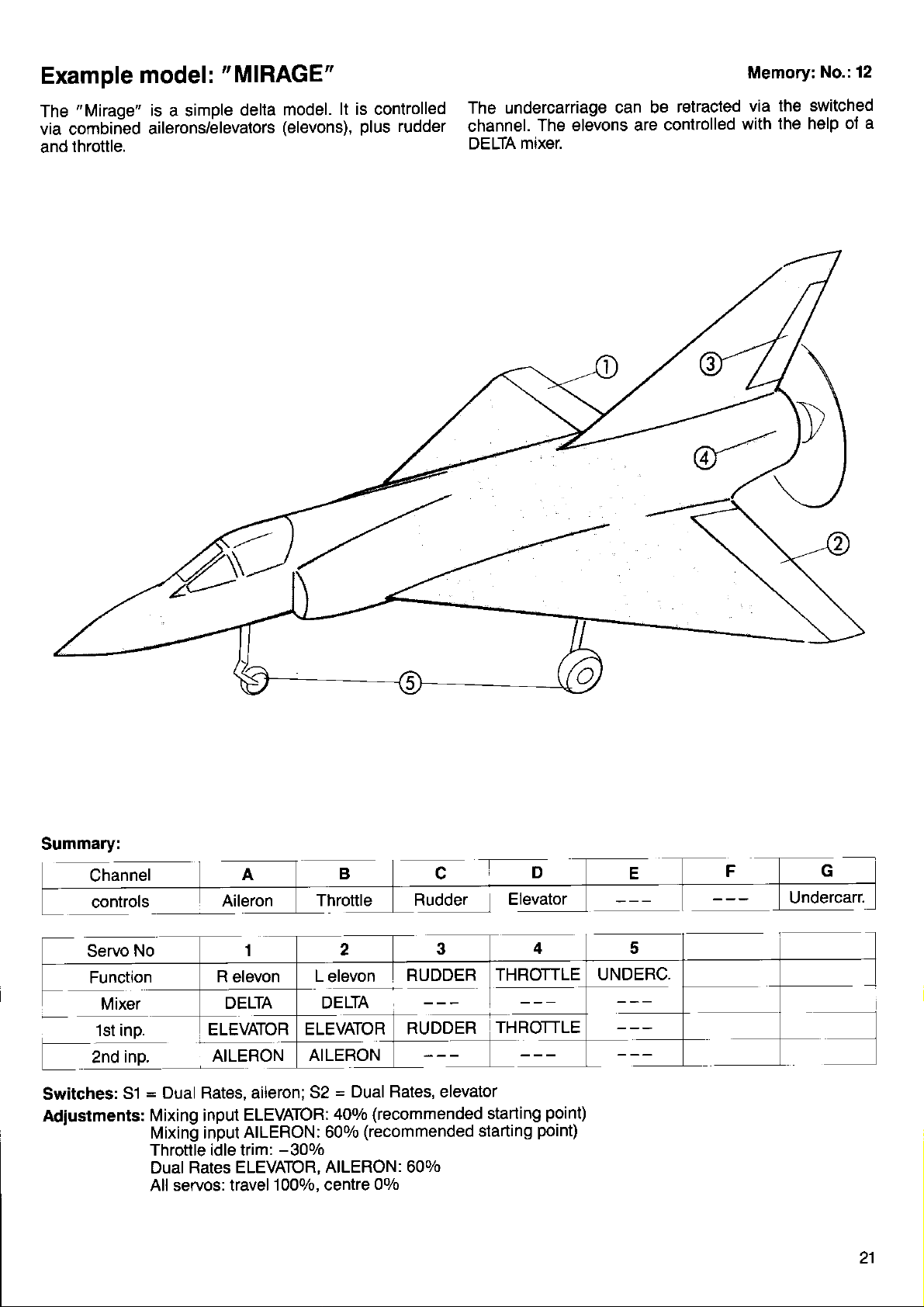
Example
"Mirage"
The
via combined
model :
is a simple
ailerons/elevators
and throttle.
"
MIRAGE"
model.
delta
(elevons),
lt is controlled
plus
rudder
The undercarriage
channel.
LrtsLtA mtxer.
The elevons are
can be
Memory:
retracted
controlled
via
with
No.: 12
the switched
the help of
a
Summary:
Channel
controls
Servo
Switches:
Adiustments:
'
No
Function
Mixer
'lst
inp.
inp.
2nd
51
DELTA
ELEVATOR
AILERON
=
Dual Rates, aileron;
Mixing input
Mixing input
Throttle idle trim:
DUAI RATCS
All servos: travel
ELEVATOR:
AILERON: 600/o
ELEVATOR,
1000/0, centre
Throttle
L
elevon
DELTA
ELEVATOR
AILERON
=
Dual Rates, elevator
52
400/0
-300/0
AILERON: 600/O
ry9q91
RUDDER
RUDDER
(recommended
(recommended
00/0
starting
rD
Elgy"to,
THROTTLE
THROTTLE
starting
point)
point)
Undercarr.
UNDERC,
21
Page 24
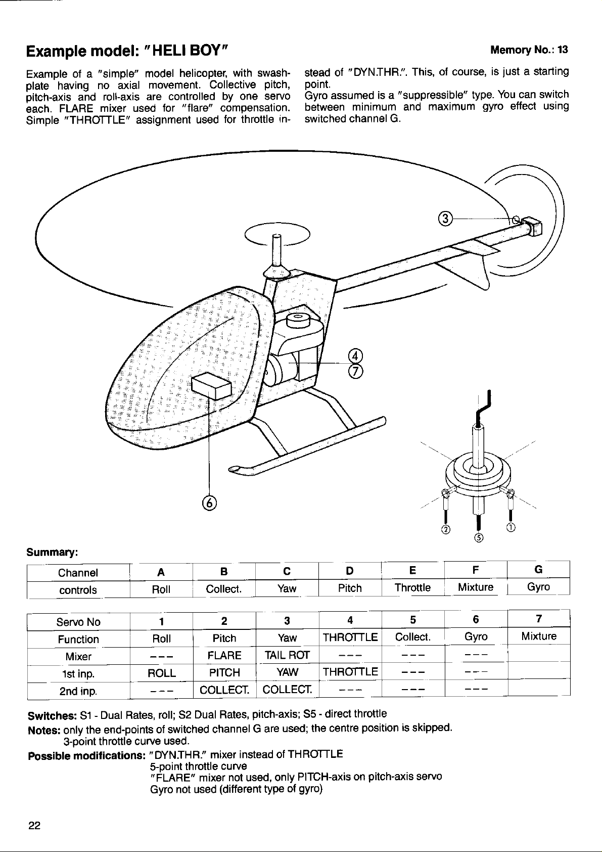
Example
Example
plate
pitch-axis
each.
Simple
having
FLARE
model:
"simple"
of a
no axial
and roll-axis
"THROTTLE"
"HELI
model
movement. Collective
are controlled
mixer used
assignment
BOY"
helicopter,
lot " flarc" compensation.
used
with swash-
pitch,
by one servo
tor throttle
in-
"DYN.THR.".
of
stead
ooint.
assumed
Gyro
between
switched channel
is a
minimum and
G.
of course,
This,
"suppressible"
maximum
type.
Memory
just
is
You can switch
gyro
No.: 13
a starting
effect using
Summary:
controls
Servo
Function
Mixer
1st inp.
2nd inp.
Switches:
Notes:
Possible
51
only
3-point
modifications:
No
-
Dual Rates,
the end-points
throttle
1
Roll
ROLL
roll; 52
of switched
curve
"DYN.THR."
5-Doint
"
FLARE"
Gyro
used.
throttle
not used
2 3
Pitch
FLARE
PITCH
coLLECr.
Dual Rates,
channel
mixer
curve
mixer
(different
pitch-axis;
instead of
nol
used,
Yaw THROTTLE
TAIL ROT
YAW
THROTTLE
coLLECt.
-
direct
55
G are
only
type
used; the
THROTTLE
PITCH-axis
ol
centre
gyro)
4
throttle
position
pitch'axis
on
Throttle
c 6
Collect.
is
skipped.
servo
Mixture
I
Gyro
Gyro
7
Mixture
Page 25

Example
Example
tuation
roll/collective
is
used.
this example
model:
helicopter
of a
system.
pitch
A separate
"DYNTHR."
"RANGER"
with the
The
swashplate
servos, and
provides
servo
is used.
71
"Heim"
the
swashplate
is actuated
"HElMHEAD"
pitch-axis
ac-
by two
mixer
control.
A
switched
means
In
ouired,
ca v
"suppressible"
between
of switched
"Heim"
as
gyro
maximum and
control
mechanics
Memory
is assumed,
"Flare"
H.
cater
which
minimum
mixing is not
for this
No.: 14
can be
effect by
re-
mechani-
Summary:
Channel
controls
Servo
Function
1st inp.
inp.
2nd
inp.
3rd
No
7)ffi
\_il--'
AB
Roll
Roll/col
HEIMHEAD
ROLL
]]i]]xollecl
PITCH
Yaw
TAIL ROT
YAW
coLLEgr.
Throttle
THR
DYN
THROTTLE
ROLL
YAW
Throttle
Roll/col
HEIMHEAD
Mixture
Gyro
GYRO
Mixture
MIXTURE
-
Switches:
Notes: Switch
Possible
31
s-ooint
moditications:
Dual Rates,
control
throttle curve
roll; 52 - Dual
H must be
3-point
Gyro
installed
used
throttle curve
not used
Rates,
(On/Off
(different
pitch-axis;
switch, 3-core
type of
55 - direct
lead)
gyro)
throttle
2.7
Page 26

Example
ExamDle of a
system.
vos, arranged
vide collective
Three servos
"HEAD-MlX"
model:
helicoDter with
The
swashplate
at
pitch, pitch-axis
are used,
mixer. The throttle
120
degrees
'B,K117"
"CPM"
is controlled directly
to each other,
in
swashplate
which
roll-axis
and
conjunction
is assigned to
control
by 3 ser-
pro-
control.
with the
"THROTTLE"
pressible" gyro
('DYNIHR.'is
is
tween minimum
switched control
unequal
board"
collective
servos.
H.
Memory No.: 15
alternative).
an
assumed,
and maximum effect
"Flare"
pitch
which can be switched
mixing can be achieved by
inputs to the
"centre"
"sup-
A
be-
by means of
"out-
and
Phase affects all rotor
Note:
change the Geometry settings,
pitch
tive
inDuts and check
head
servos
that thev are correct,
equally. Before
be sure to set up the collec-
you
Summary:
Channel
controls
Servo
No
Function
1st inp.
inp.
2nd
inp.
3rd
Ro/Co/Pi Ro/Co/Pi
HEAD-MIX
ROLL
PITCH
coLLECr.
HEAD-MIX
ROLL
PITCH COLLECT.
coLLEgr.
r 4th input: Geometry
Switches:
Notes:
51
Switch
3-Doint
Piich
(assuming
Collective
Possible
modif
24
-
Dual Rates,
control
throttle
input value
roll; 52
H must be fitted
curve used.
for
120 degree
pitch
input same
ications: s-point
Gyro
"centre
-
Dual Rates
(On/Off
servo"
arrangement)
for all three servos
throttle
not used
HEAD-MIX
pitch;
switch,
twice as
curve
(different
type
Ro/Co/Pi
PITCH
-
auto-rotation;
53
3-core
great
as for
gyro)
of
4f5I
Throttle
THROTTLE
lead)
"outboard
Throttle
Yaw
TAIL ROT
YAW
coLLEgr.
input:
sth
55 - direct
servos"
throttle
Gyro
GYRO
Phase
Mixture
MIXTURE
Page 27
i:
Assigning
f unctions
ot the
belore
new model.
very complicated
you
li
the
ried
lf,
swapped
right" and
signed"
We can difterentiate
ing:
Assigning
1.
functions
The examDle
egory
hand
Assigning the
2.
For
vo connected
evator:
swashplate
i,:
linking up, the
or
servos
and
setting up
you
have owned
"PROFI
out this
for example,
those
Another example
slider
example,
or
actually use
can
But don't
mc 3010",
"assigning"
you
connectors
"elevator
Junctions to sult
the transmitter
we
is to control the
this might
to receiver
in a helicopter
with a 12o-degree
is the first and
process
waiting for
another
have changed
over,
|eft", then
mentioned above
servos to
transmitter
most
which has to
the equipment
run and
you
process
between
would be
mean that servo
output
that servos
hide - there's
you.
radio control system
probably
have
without realising
switches
in order to set
you
have already
preference.
your
two torms of
controls
falls into
to decide
model's airbrakes.
the control
2) is to operate
1, 2 and 3
actuation system.
controls,
important
be carried
to the control
functions
No. 2
control
part
out
to control
nothing
beJore
already
up
that the
car
it.
round,
"aileron
"as-
assign-
this cat-
left-
(the
ser-
the el-
control a
earlier
On
facility
essential.
and
The assigning
with the
a
want to cover
page
Why do
This
ertheless
1. Many
or
a comDuter
much more
soecific
"left
2. Terms such
familiar
when
lective
tive
the receiver, and
volve that
rectly.
which can be
ln short:
Assigning draws
for the computer
was
useful.
45, under
we have to
question
information.
stick. uo/down".
to any
assigning
pitch"
pitch
lt
radio control
provided,
not
you
But
procedure
"miiing"
this
the title
is not all that
will try. Here
we
of the transmitter's
and
likely to
as
modeller. lf
the servos,
servo,
signal
prevents you
will always be
that all
channel
difficult to
systems
and
will soon
ot control
point
assign anything?
its
work in a sensible
For example,
"left
you
will automatically
a clear
your
in
see
can also be
here.
"Mixers".
easy to answer
are some
functions are carried
related software.
aileron"
you
that servo
can be
mixing arrangements
having
sort out.
line to
transmitter.
"total
this
in fact
that it
functions; but
lt is discussed
of the
"elevator"
"right
or
"tell"
certain that
available
to worry about
follow: for
adjustment"
it is not absolutely
is highly
extended
simply;
reasons:
The software
if it is
way
instead
collective"
transmitter,
the
No. 3 is the
the collec-
at socket
be carried
practical
to cope
we don't
in full
on
nev-
out
given
are
"coF
3 on
which
out cor-
details
you
and
by
is
of
in-
How to assign
transmitter
the
From
using
"BlG
The
display
the Status
key sequence
the
LIFT"
Display,
is
the model
still
will look
rt_:t:ttlTFjUL
rTElll.H
Select
the
The transmitter
controls
ter
control
A - D are
also
the
E and F are
printed
G
H
need these
connect
with those
"CONTROr
r
is what
t:l
key. This
Z
r tl I
(A
l) in the display.
to
starts to
printed
right-left
is normally
-
|
are
flash.
"A'
appears.
the symbols
on the
movement ot the
the two
on the transmitter
(as
not available
channels,
them to the
letters.
t_:Ltt..lTF:uL5
LEF:r:ttl
responds by showing
Now
transmitter
standard)
See
controls
move to the
@ZN.
like this:
We assume
in the current
L:EE
U5Fi-l'll
(transmitter
you
will see:
Press the
press
the
Try using the
for the
on
you
main circuit
Page
stick units.
casing.
right-hand stick
sliders; these
casing.
"switched
the
the standard
install extra switches
can
Z
"Assign"
again that
memory
l"lt:tr
iir
control) by
one
key repeatedly
El
key as
E
For example, C
letters
channel"
transmitter.
board sockets
pressing
oJ the
The let-
key.
Z
well.
The letters
unit.
are also
marked
menu
01.
nine
until
are
is
7.
No.
you
lf
and
now this
Bv
m-enu
In our example,
press
the
function which appears
The
(in
flash
Now things do
lf
vou
tions,
in
tions
AlLERon
ELEVator
RUDDeT
THROTtIe
2THR
SPOlLer
FLAP
RETRAct
]iOWHOok
MlXTUre
you
As
used functions:
Columns
Column 3
(including
Column
"AUX.
Wewill explain
much should be
you
S
our example
press
ihe transmitter
turn:
(tor
z ens.)
see,
1 and
4 is
1 - AUX.4"
the transmitter
select
leave the
key.
get
a little
the
E
ROLL-axis
PITCH-axis
YAW-axis
COLL.
GYRO
these
2 for fixed
Jor model boats
electric-powered
for the
are used
",/,"
obvious:
control.
"A"
showing
"AlLER"),
(or
include all the
after
more difficult.
key to
E)
will offer
PITCH
'extra-special
-
the
you
SHIPRUDeT
MOTOR
MOT.2
wing and
and electric-powered
aircraft).
when no other
last option
in this
letter now starts
the
leaf through
the following
(etectric)
most commonly
helicopters;
functions"
line of the
(flashing)
(etectric)
term
-
very soon!
and
to
the func-
Junc-
1
AUX.
o
AUX.
4
AUX.
models
1- 5.
"fits".
25
Page 28

We have
you
"pre-defined"
don't have to type
functions
these
anything in; all
select the right option. There is
you
select the terms from the list
gent"
transmitter works out what
next, and
The
is to carry
We will assume a model
prepares
itself
accordingly.
best way of coming to terms with
out a sample assigning
glider
ailerons and spoilers.
The right-hand
the left-hand
erated
with
It is obvious
hand stick, the left-hand
are not
Now we can
the
First
Key
going
"ASSIGN
the elevator:
leaf through with the
Z;
pears
under this
there is nothing
stick is to control
stick the rudder. The
the right-hand
slider.
that the forward/back movement
slider and the
to
be used.
get going
-
provided
CONTROLS" menu.
El
(right-hand
stick, forward/back).
the display already shows ELEV,
to be changed here)
Now the ailerons:
Key
Key
Now
Key
leaf through again
Z;
pears (right-hand
leaf through
N;
rudder:
the
leaf through
Z;
using
stick,
until AILER appears.
until A appears
left/right).
Key
leal through
!;
until RUDD appears.
Finally the spoilers:
Key
leaf through until F
Z;
PS.: if
you
wish,
appears
you
can asslgn the stick func-
tion B to the spoilers instead
Key
Sl;
leal
through until SPOIL appears.
you
for
you
also another reason: if
above,
you
are
this
so that
have to
your
likely
do
"intelli-
to ask
procedure
exercise.
with
elevator,
rudder,
elevator and aileron;
spoilers are to be oo-
of the left-
switch
you
that
and
E)
keys until D ap-
El
and E until G ap-
"No.
are still at
line
Ohe
left/right).
(left-hand
(right-hand
the
of
stick,
slider).
slider
is
That's
controls
There is
almost all there is to it. But what of the
(8,
E, G, H,
D?
a danger here that something has
assigned to these controls when the memory was last in
-
use
very least
see
something
it would offend
THROTTLE
it: this is where
lect the
them to
controls B, E, G, H, and I in turn,
",..'.",
This is typical of
even when they are
have
to tell them expressly, otherwise
something
unexpected!
The tidy-minded modeller
7"
transmitter controls to z .
be unnecessary. lt is
considerable conf
you
Now
with
really are finished,
@
key.'
the
which
could cause
the sensitive
against B, for
"
"
".
,
comes in. As described
example.
unless that has already
way
the
computers have to
supposed to do nothing at
should always assign
/',
...
€VOn
always
worth
usion.
and can
Incidentally:
so
In the
sequence for the assigning
out
And
You might
transmitter
Aileron"
example above we deliberately chose a
process; you
just
one
how
more
quickly
this can all be
thing:
have the bright idea
controls to the same function,
"C
and
=
Aileron". In that case the
ter would not know which instruction it
posed
has instrubted it to
valid
entry
.
1.
2.
3. Enter the name
to act upon, For this reason
consider the
entry. In our
"A
=
Aileron",
you
lf
want
rowrng:
Copy the results of
Switch
In
following
the
you
to,
memories; to No.
example
and accept
can skip a few
your
work into memory No.02;see
"FLAMINGO";
examples we assume that
02. See
see
it would ignore
pages
page
page
unused
already been
problems.
At the
glider guider
You've
guessed
above, se-
and assign
been done.
treated:
be
all,
they might do
unused
when it
appears to
doing, as it can avoid
leave
the menu
complex
will
soon find
done.
of assigning two
e.g.
"A
compu-
was sup-
programmer
our
"last
one" as the
"C
=
Aileron".
point
at this
43.
43.
you
have done all this.
the
and do the fol-
page
41.
to
you
-
tirst
How to assign the servos
"assigning
By
transmitter
which servo, i.e.
To make it
is designated with the number of the receiver output
socket to which it is connected:
The servo connected
fore servo No.
2, and so
At this
of which
strongly
zo
on.
point you
number
recommend
the servos" we mean inJorming the
which tunctions
you
determine
quite
clear which servo we mean, each servo
Receiver
are to be carried out bv
the
B
1ls
z
3
5
6
7
functions.
servo
Servo No. 1
Servo No. 2
Servo No. 3
Servo
Servo No. 5
Servo No. 6
Servo No. 7
to receiver outDut No. 1 is there-
1,
that connected to output 2
is
have a more or less unrestricted choice
controls
which function. However, we
you
that
adopt a
"standard"
No. 4
servo No.
se-
quence,
this makes
as
the
whole
business of setting up
a new model easier to understand.
Our
suggestion
Servo
Servo
Servo
Servo
Servo No. 5
No. 1
No. 2
No.
No. 4
(adopted
Aileron
Elevator
Rudder
3
Throttle
Aileron 2
from the " ROYAL mc"):
(if
separate aileron
are used)
-
Servo
In
special cases
faces)
No.
you
I :
6
auxiliary
(e.9.
wings
will need to
functions
with multiple
arrange
things
control sur-
difterently; but
more of that later.
Now the
In the displays which follow we assume that
moved
preamble
memory
to
is
over,
"02
we
FLAMINGO", as described
can
get
down to business.
aDove.
Starting
from the
reach the
"ASSIGN
t155I
Status display,
SERVOS" menu. You will see this:
riH
5EFiLrü i
press
@ZNtr
1
TrJ llILEFiut'l r
servos
you
have
to
Page 29

Press the
"leaf
through",
to 9, then start
rise
bers
As an
the
The
example, stop
key.
Z
"3"
will stop
N
The
key.
pressing
by
at
flashing, and
"1"
starts to
the E or
again
No.
3
flash. Move
keys. The
E
from 1.
("3"
flashing),
and
the servo function
on, or
num-
press
in the
bottom
through
line
the options
the correct
you
leaf
lf
will offer
quence.
through
you
The series
will llash instead.
with the
Here
and
E
function to that servo.
with the
again
large number of
a
runs as
further functions
follows:
you
again
keys and assign
El
key, the transmitter
E
can
in se-
leaf
AILERON
ELEV(aro0
RUDDER
THROTTLE
2.THBOI
SPOILER
FLAP
B ETRAT.
TOWHOOK
MIXTURE
That's
closer
"first
The
tunctions
trol
quite
look:
lot to assimilate
a
division"
lor fixed-wing aircraft
in the transmitter
followed by
the specialised
and electric-powered
-
AUX.1
into the usual
Now
Here
ably been
mixers
"ready-made"
called
More
ple,
the
ample
trol surfaces
both
servos
then
must send
and 3.
each
You have
"
mixed
Right at the
table,
oplion.
left in the
However,
for
And one
l{
"
neutral
this to
AUX.4 are
pattern.
to the second
we meet
with
looking
listed
here are stored
up.
on this
we will
"Assigning
in
just
of a'V-TAIU'.
are
servos are
like this:
Servo
Servo
No. 2 controls:
No. 3 controls:
the transmitter
the elevator
you
All
need to do after
signal to send.
assigned servos
control f unction".
end of the
you
will see
A servo
shop
you
will see later that
it, and that
the " .
more tip:
you
connect
"
".
is
.
assigned,
position
set the servo
torm, and
window - that's one
ROLL
PITCH
YAW
COLL. PITCH
GYRO
includes
control assigning
models. As
for special
group
the
for in vain In this book
the
explain
servos"
As
each operated
"V-tail
automatically
list, as in the earliel
"
"
.'.
.
which does
"
.',
a servo to a
then
signal
(and
itself to
ooint.
SHIPRUDeT
(tail
rot)
in one
MOrOR
2.MOT
(electric)
go.
Let's take
(electric)
the familiar standard
and helicopters,
process.
functions
functions
"mixers",
for model boats
you
have
which
which
you
have
so far.
in the transmitter
just
need to be invoked,
section.
why the mixers are
process.
probably
you
Using our exam-
included
look at the ex-
Let's
the two con-
know
by one servo,
you
servos".
lt
now assign the
V-TAIL;
V-TAIL,
understands
rudder signals to servos
and
that is tell
2 and 3 as
it how much of
the
assignment
again - an apparently
"nothing"
could
way to save
good
very
useful.
option
can be
there is a
receiver output
the servo
receives an accurate
nothing else).
You can use
its exact mechanical
a
con-
as
They are
guessed,
not fit
do
prob-
All the
in
or
in
and thus
that it
2
"V'tail"
useless
really be
money.
reason
to which
centre
AUX. 1
AUX. 2
AUX 3
4
AUX.
FIXEO VALU
But back
ELEV +
V . TAIL
V-TAIL
FLAPERON
AIL.BR.
SNAPFLAP
QUADRO
DELTA
to the more
Don't be afraid
times;
let's
aileron
sign them as
the transmitter
discuss
"electronically
servos:
follows:
No. 1 controls:
Servo
No. 5 controls:
Servo
This ensures that
signal.
tion entitled
More on setting
"Transmitter
Let's imagine that
of which
each
travel and
servos.
control
trol functions
differential.
You could
lunction. The same
(even
But take care:
Always assign
left.
one
correct:
servo
you
lf
will work
Alternate does
outputs must be directly
not keep to this
do
incorrectly.
TAILROT.
HEIM
FLARE
+
"normal"
of assigning
knows all
HEAD
DYN. THR.
functions.
one control
about that.
differential"
you
as
need two servos
AILERON;
AILERON.
both servos
will receive
up aileron
control adjustment".
you
have a
you
wish to be
adjustable
You would
assign all
the
four servos to
applies to all
"
mixed" f unctions!).
control surtaces
not necessarily
sequential.
rule,
USR . MIX1
-
IVIIX
-
IVIIX
USB
USB
-
-
function several
For example,
ailerons,
for this,
with
you
the aileron
differential
model
in the Sec'
with 4 ailerons,
separately
then need 4 aileron
"Aileron"
the
the other con-
alternately:
one
mean that the
your
aileron differential
MIX2
MIX3
2
as-
Jor
right,
27
Page 30

Finally a
A model
ailerons.
GO" again).
First
Ailerons
Spoilers
Aero-tow release is operated by
Now to the assigning
(Note: you
assigned to the correct {unction when
servo
press
function
need to do this.)
practical
glider
sooilers and aero{ow release
you
make the connections
Elevator is operated by servo No. 2
Rudder is
are
are operated
will find that some of the
No. Don't
the keys
appears again. Of course,
example
with elevator and rudder, differential
operated by servo
operated
procedure,
put
be
"round
in
abbreviated
the receiver end:
at
No.
3
by Servos
by servo
off by this. Just for
the
clock" one time, until
No. 1
No. 4
servo
as described above:
servos are already
you
form.
"FLAMIN-
(the
and 5
No.
6
you
select that
never
practice,
the
actually
key; then leaf through with
N
key; leaf through until
Z
key; move
N
key; leal through with the
Z
appears.
key; leaf
N
key; move to
z
key; forwards
S
key;
Z
key; one back to
N
key; @ key until
Z
key;
N
key; E key
Z
All done.
Leave the menu
times, and
back
"AILERON"
leaf
through
you
"1"
to
"AILERON"
with E to
again
again
"4",
"SPOILER"
with
"TOWHOOK"
until
with
the
are back at the Status
"ELEV"
with the
with the E key
with the
E
E
appears.
key
El
El
with the E key
"5"
El
flashes
"6"
until
flashes.
key;
then
key
El
"2"
until
'RUDDER'
until
key.
key
flashes.
three
El
Display.
flashes.
more
';-;.
In
guage
servos" doesn't
more a
end" of the
produced
modified at all after they have been transmitted,
tect of any adjustment
made
In the following section we will describe
sic adjustments
Reversing
is
note this
never reversed - think
mixer: elevator correct,
the
rect. Moral: only
later.
You can also adjust the
"electronically"
Finally we
-
While
two
the exoerienced
to a niln
In this Section
ple"
is concerned
section
We will discuss
GO".
How to
the direction
Starting
"
Servo adjustment"
You will see
you
case
we modellers
matter
the servo itselt.
at
certainly
point
"servo":
separately
reversing servos is almost a daily
other Jacilities are
level
adjustments.
(page 45).
not tamiliar with
are
prone
are
mean
of adiusting and setting up the
transmitter. The
by the transmitter, and since they are not
which can be made to the servos.
the
direction
the most important aspect of this.
right now: the servos themselves are
rudder is now correct, but elevator
reverse
at the transmitter.
have
the
for
each side
modeller who wants to tune
refinement.
of
we
with mixers. This
this in conjunction with
attacking the servo
signals
is the
of servo rotation
for a moment
rudder incorrect. Now reverse
possibility
more for
are concerned
There is a more complex side,
same as
mixer inputl More on this
the
neutral
of adjusting servo travel
of neutral.
is
reverse
of servo
from the Status
this:
display,
menu.
rTE:r,r+E:Etr.
LL:EHTF:E
-;t,J I TI-HT
rather
the
to
use,
for
position
special
only with these
explained
sloppy
"adjusting
itself. lt is
each servo
if it had been
in
detail the ba-
(servo
of a simole
of the servo
necessity, the
cases, and
his
in the Mixer
"02
rotation
press
to reach the
Z
@
LIHITt
"servo
the
reverse)
Please
is incor-
svstem
"sim-
which
FLAMIN-
lan-
the
are
ef-
V-tail
for
Press the
After this vou will see:
Z
key
to select
rSEF:.
L+ l
you
First
want to revetse.
Press
Now
the desired servo. Once
want,
travel) begins to tlash.
Please note: the travel display
it - the
last
Now comes a typical example
useo:
Press this key, and
That action reversed the servo.
standard
control
"Mixers"
You leave the menu with the
twice
other
Fatal error; or a special
Really this belongs to the
but this is
How come this
You
good.
What's
Now, what
when setting the servo travel.
again
tem.
your
lf
This
For example:
that
rection ot the change in tail
tion must always occur
tional to the tail
have to tell the transmitter which servo
the
you
can
press
prefix
set.
case, when the servo concerned
function.
Section.
more
successful expedition
where
right - the servo runs to the
apply
You apply
happened?
reverses the movement and
servo
unusual
is
exactly
rjlrjr:i rj+
key. The servo No.
Z
press
the
the
you
you
now needs to be reversed,
key. The
fl
We will
return to
you
feature is normally an error?
left
have done is this:
leature is important
mixing tail rotor and throttle. In this case
what is required - regardless of the di-
rotor
"TRAVEL
1: t:tILEF;üH
tl I LEFjr
and
El
you
"+"
turns
cover
your
"feature"
"Travel
will look tor it.
-
the servo
in
deflection.
keys
E
have
displayed
percentage
has
depending
of how the
into
this
key;
m
starting
into
the
runs to the right again.
Turning it
for
rotor,
the throttle
the same
+ REVERSE"
you
("1")
starts to flash.
leaf
to
a symbol
"-",
This was a simple,
area
and
point,
land of the keypad.
adjustment"
you
removes the
the
direction,
through
the one
display
in front of
on how it was
El
or vice versa.
has no mixed
in detail in the
pressing
by
after
-
right
turned
press
so
past
past
back
El
helicopter
compensa-
to
you
(the
set
key is
El
yet
an-
section,
far, so
"0"
zero
prob-
once.
pilot.
propor
zö
Page 31
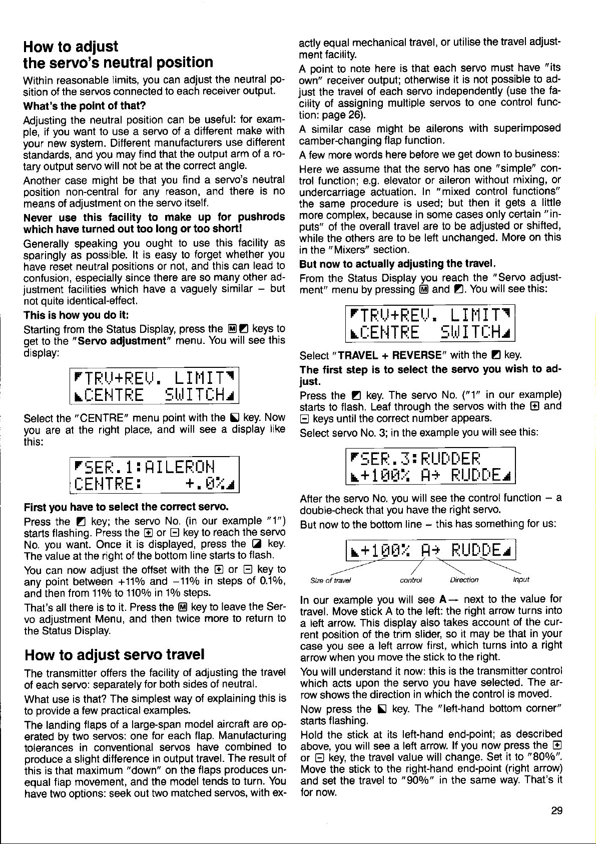
How to adjust
servo's
the
Within
sition
What's the
Adjusting
ple,
your
standards,
tary
Another
position
means of adjustment
Never use
which have
Generally
sparingly
have
confusion,
justment
not ouite
This is
Starting
get
display:
reasonable
the servos connected
of
the
you
if
want
new system.
output
case
non-central
as
reset neutral
facilities
identical-effect.
how
from the Status
to the
"Servo
neutral
Iimits,
point
of that?
neutral
you
and
servo
might be that
this facility to
turned out too
speaking
possible.
especially
you
position
to use a servo
Different
may find that the output
will not be at the correct
for
on the servo
you
positions
since there
which have a
it:
do
adiustment"
rTFjil+E
rt-:Et{TE:E
"CENTRE"
Select
you
this:
the
are at
the right
r:;EFj.
place,
1 : H I LEF:r:rl.{
|_:EHTFIE:
you
First
Press the
starts
No.
The value at
You can
any
and then
That's all
vo adjustment
the Status
How to
The transmitter
of each
What
provide
to
The
erated
tolerances
produce
this
eoual
have two
have to select
the servo
key;
Z
flashing.
you
point
Press the E or
want. Once
the right of the
now adjust
between
from 110/o to
there is to
Display.
the offset
+110/o
it. Press the
Menu,
it is displayed,
1100/o in 10l0 steps.
and
adjust servo
offers
servo: separately
use is that?
a
landing flaps
by two
in conventional
a slight
is that
maximum
flap movement, and
options: seek
The simplest
practical
few
of a large-span
servos: one
difference
"down"
position
you
can adjust
to
each
can be
of a ditferent
manufaclurers use
you
find a servo's
reason, and
any
itself.
make up
long or too short!
ought
lt is
Display,
Er,r.
menu
to use this
to forget
easy
not,
or
and
are so
vaguely similar
press
menu.
L I r'lI Tr
I TuHr
5til
point
with the
and will see
+.
the correct servo.
(in
No.
E
bottom
with the
and
then twice
travel
the facility
for
both
examples.
for each flap.
servos
in output travel.
on the
the model tends
out two
matched servos,
our example
key to reach
press
line
-110/o
key to leave the Ser-
E]
of
adiusting
sides of
way of explaining
model aircraft
have combined
flaps
neutral
the
receiver
useful:
the
You will see
for exam-
make
arm of a
angle.
there
pushrods
for
facility as
whether
this can
many other ad-
E Z
!
a display
po-
output.
with
difJerent
ro-
neutral
is no
you
lead to
-
but
keys to
this
key. Now
like
Ell:r
"l")
the servo
the
to
starts
or E key
E
in steps of 0.1ol0,
more to
neutral.
Manufacturing
The result of
produces
to turn.
key.
Z
flash.
return to
travel
the
this
are op-
un'
You
with ex-
to
is
to
mechanical
equal
actly
facility.
ment
A Doint to
own" receiver
just
the
cility of
tion:
A similar case
camber-changing
few more words
A
Here we assume
trol function;
undercarriage
same
the
more complex,
puts"
while the others
in the
now to actually
But
From the Status
ment"
note here
output;
travel of each
assigning
page
26).
e.g. elevator
actuation.
procedure
of the
"Mixers"
overall travel are
menu by
rTF
multiple servos
might be
f lap f
here before
that the servo
because
are to be
section.
adiusting
Display
pressing
Lr+F;Er,r,
rL:EtlTF:E
Select
The first step
iust.
Press
starts
Q
Select
"TRAVEL
the Z key.
to flash.
keys until the correct
servo
r::EF:.
r+
After the servo
double-check
But now to the
of tnvel
Size
In our example
travel.
a
rent
case
arrow
You will understand
which acts upon
row shows the
Now
starts
Hold the stick
above,
or E key, the
Move the
and set
for
Move stick
left
arrow.
position
you
when
press
flashing.
you
the travel
now.
see
stick to the
+ REVERSE"
is to
select
The servo
LeaJ through the
No.
in the example
3;
l Ut:tl.:
you
No.
you
that
bottom
you
A to the left: the
This display also
of the trim slider,
a left arrow
you
move the stick to
it now: this
the servo
direction
the
will see
key. The
!
its left-hand end-point;
at
a left arrow.
value will change. Set
travel
to
travel, or utilise
is that each
otherwise
independently
servo
ailerons
unction.
we
or aileron
"mixed
In
is
used;
in some cases
but then
to be adjusted
left unchanged.
the travel.
you
reach
and
El
L I i'1I
the travel
servo must
it is not
get
has one
Z.
possible
to one
with superimposed
down
"simple"
without
control
it
only certain
"Servo
the
will
You
T1
StrlITr::Hr
with the
the servo
No.
servos
number appears.
f,: E:l_l[rlrEF
H+ F:l-l[i[!El
will
have
line - this
control
will see
in which the control
right-hand end-point
"900/0"
the control
see
the right servo.
has
Direction
A- next to the
takes account
so it
which turns
first,
the right.
is the transmitter
you
have selected.
"left-hand
you
lf
in the same
Z
you
("1"
in our
with the
you
will see this:
something
right arrow
may
be
bottom corner"
now
adjust-
"its
have
to ad'
(use
control
to business:
mixing, or
functions"
gets
or shifted,
More on this
see
key.
wish to ad-
function
lnput
turns into
of the cur-
that in
into a right
is moved.
as described
press
it to
(right
way.
fa-
the
func-
con-
little
a
"in-
adjust-
this:
example)
and
El
-
a
for
us:
value for
your
control
The
ar-
the
E
"800/0".
anow)
That's it
29
Page 32
you
Are
The servo
stick
"stick
The servo
stick
"stick
lf
see
900/o.
The
irrelevant when adjusting
ception: see
travel
Leave the Servo
key.
Now
It
when making these
ooint
iikely
trim slider
The same applies
functions
ments, the right and
down arrows.
All
of the servo concerned;
though
There
travel
you
case the servo
the stick
less than
the
you
it to
tral). Quite
iust at
beginning
travel
the left
to
|eft".
travel
to the right
right".
you
that
prefix
makes no ditference
percentage
could
n key.
move
the right
move the stick to
now
the travel value alternates
in front of the
below); it shows
is reversed; see also
a few more
is
the direction
to confuse
instead, and
which correspond to
there are exceptions).
is no reason
adjustments.
set the
in that direction.
zero,
The servo will
the stick to the
(as
why
the moment!
feel
to
which
is
which
adjustment menu by
points:
you, you
values refer to the
left travel of the stick
would
i.e. a negative
you
you
at
corresponds
selected
corresponds
is
selected
travel value shown
how far
adjustments;
in which the arrow taces.
leave the stick at centre.
to all servos/control
left arrows are
this
why
For instance,
not move at all
You can even
left, as well as
have not changed
might want to
home with the system?
moving the
to
and then adiusted
moving the
to
and then
right
and
servo travel
whether the servo's
page
can
is usually
you
now move to the
"Servo
28:
you
the only
move
forward/back stick
replaced by up
normal nominal
should
in
the
value,
do that
adiusted by
you
left
then
between 80
is normally
(there
pressing
move the sticks
the
45
not set extreme
when
simply
by
when
that side
is an ex-
reversing".
important
lf it is not
corresponding
functions. For
degrees
example above
to zero;
you
set the travel
pressing
right when
you
of neu-
is
beyond
by
will
and
whole
the
E)
move-
and
travel
(aF
in that
move
to
move
us
-
Caution
travel to zero on both
that the servo
be
some
you
will have an apparently
which will drive
insanity . . .
The other side
one receiver
the servo
Servo
ting of up to
using this
servo
jamming
of
also like to bear
than 45 degrees usually
ment, due to the
ages.
How to
With
inputs exceeds
face
flaps at the
travel
you
lf
"LlMlT"
a trap
reason, but then
travel to zero by
travel can also be
lacility excessively,
(linear
limit servo
mixed functions it can
(mechanical
"LlMlT"
limit
are still at
key and
r::EFi.
for the unwary!
sides ol
does not
you
uncomfortably
of this coin:
output, check
1100/0 is
output servos
the
launch
possible.
mechanics
in mind that
geometry
maximum travel
the
limits), e.g.
position.
help.
can
"Adjust
the
you
will
:
1
LIIiIT:
you
Now
servo
Return
Full travel
Caution:
mitters
can set
separately,
to the Status display
is resumed
when data
the LIMIT
the maximum
for each direction.
when
is transferred
values are
Please don't
neutral. The
you
move at all.
forget that
nonJunctioning
you get
if
first whether
mistake!
set to more than
we
as, with certain
particular)
in
mechanically.
an output travel
provides
of standard
lf
you
have done
to the edge
close
"nothing
you
not recommend
do
you
very little extra
mechanical
travel
occur that the
mixed ailerons/flaps
Here the
SERVO"
following:
the
see
sum of mixer
of the control sur'
variable servo
menu,
H I LEFIÜI'I
+
1ül:tilr
possible
with
@ @ El.
you
erase
not transferred.
travel
a model
between
set the
result would
this for
do
it,
channel,
of
all" at
at
have set
usual: a sel-
types of
run the
You might
two trans-
risk
of more
move-
link-
with
press
the
for each
memory.
make travel
How
In the
sequence @ZZ
travel
rendered
physical
Let's
then
play
to
"swlTcH"
inouts for the servos
switchable.
switch
look at an
move
look something
will
is assigned to
to the
rSEFI.
l LEE::
rtl
the case,
lf this
the
Now
switch
servo
30
is not
keys.
EIE
press
between
1
by
51,
pressing
inputs switchable
menu, which
(starting
"switchable"
By
example: switch
"SWITCH"
like this:
you
trom the
can be switched
that travel
to memory
menu
1 : FLHFEFIIH
Ul'l
press
AlLeron
and
the two
the
El
inputs
Z
will llash.
key.
and
Alleron
reach
with the key
basic display),
ON/OFF
mean that a
we
input.
07 SALTO,
(E)ZZ).
The dis-
r
select servo
You
and
1 with
now
can
FLAP
At bottom
wavs switched
all
switched
or
tor
practice
In
1.
2.
3.
4. Return
Another
lf
servos
pear
way
have been switched
menu.
been assigned
wrong
in
Move to the
Select servo.
Z:
Select
fl:
Switch ON/OFF
El:
Repeat until
have been
trap tor the unwary:
which are
not to
you
intended,
The second
position.
you
right
and
the system
to
respond to
will
while the
on,
out using
"SWITCH"
input
you
2. and
ooint
covered.
controlled
then
OFF completely
possibility
to a
that the
see
the 53 switch.
works as
menu.
the
with
have covered all
continue until
the transmitter
you
may find that
physical
aileron
FLAP input can
follows:
key.
El
by mixed
is that the
switch
input is al-
the inputs.
all servos
functions ap-
controls
the inputs
in the
"SWITCH"
inputs have
which
is in the
be
in the
Page 33
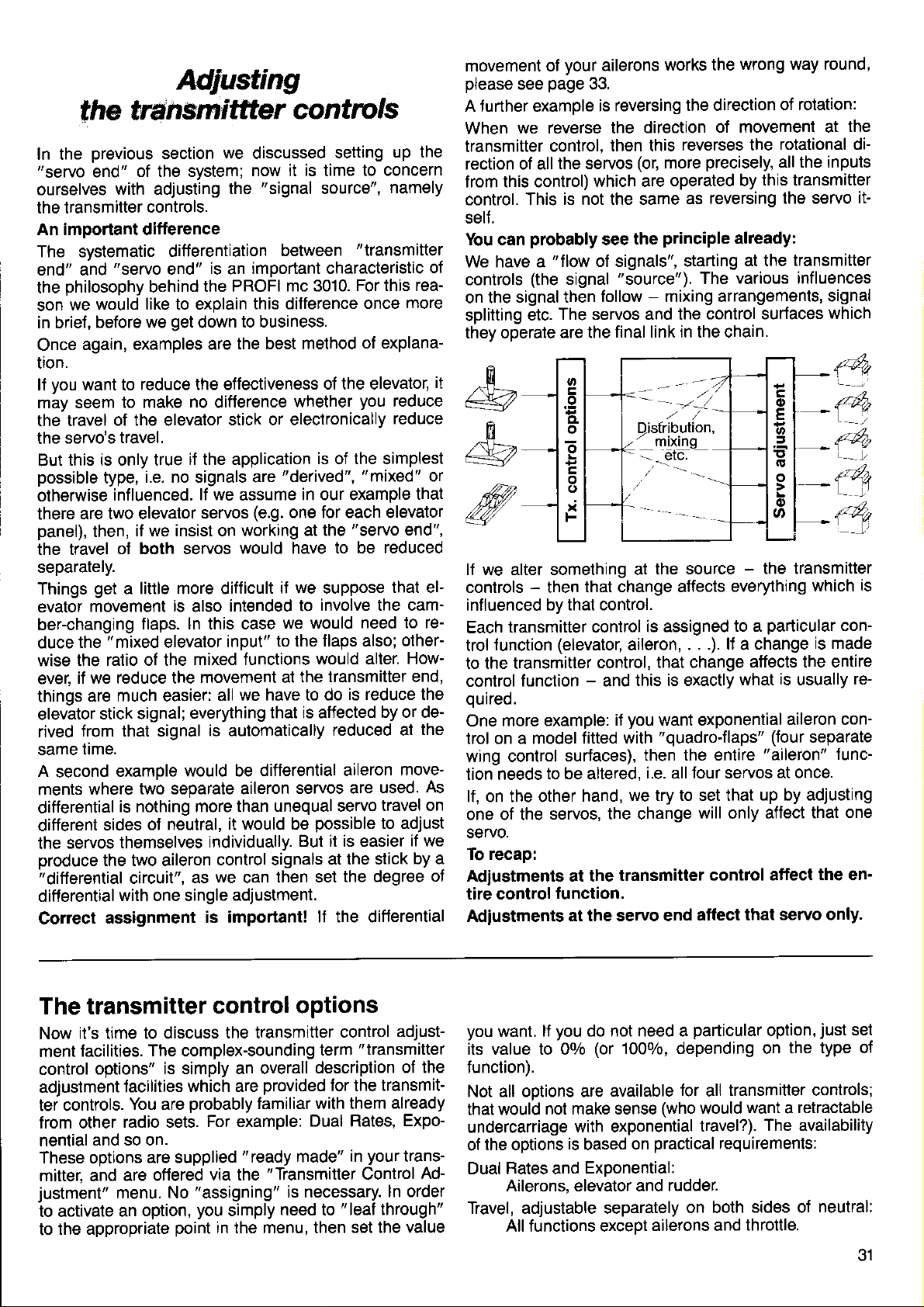
Adlusting
tfie lransmittter
In the
"servo
ourselves
the transmitter
An important difterence
The systematic
end" and
the
son
in brief
Once
üon.
ll vou want to
mäy seem
the travel
the servo's
But
possible
otherwise
there
panel),
the travel
separately.
Things
evator
ber-changrng
duce
wise the
ever,
things
elevator
rived
same
A
ments
differential
different
the
produce
"differential
differential
Correct
previous
end"
with adjusting
"servo
philosophy
would like to explain
we
before we
,
again, examples
of the elevator
this is only true
type,
influenced.
are two elevator
then,
get
movement
"mixed
the
ratio of the
if we reduce the
are much easier:
stick signal;
from that signal
time.
second
where
sides
servos
the two aileron
assignment
section
of the system;
controls.
ditferentiation
is
end"
behind
reduce the effectiveness
to make
travel.
i.e. no signals are
it we insist on
of both servos
a little more difficult
flaps. ln this case
example
two separate aileron
is nothing more than
ot neutral,
themselves
circuit",
with one single
the PROFI
get
down
are the
no
difference
if the application
lf we
servos
is
also
elevator
mixed functions
movement at
everything
is automatically
would be
individually.
control signals
we
as
is important!
contrcls
we
discussed
now it is time
"signal
the
between
important characteristic
an
mc 3010.
this difference
to business.
best method
stick or electronically
"derived",
assume
(e.9.
working at the
would have
il we suppose
intended to
we would
input"
all
it would be
to the flaps also;
we have to do
that ls affected
differential aileron
unequal servo
then set
can
adjustment.
setting
to concern
source",
"transmitter
For this rea-
once
of explana-
of the elevator,
whether
in our example
one for each elevator
the transmitter end,
servos are
But it is easier
you
is of the simplest
"mixed"
"servo
to
involve the cam-
would alter.
reduced at
possible
at the stick
lf the differential
reduced
be
need to re-
is reduce the
by or de-
used.
travel on
to adjust
the degree
up the
namely
of
more
it
reduce
reduce
or
that
end",
that el-
other-
How-
the
move-
As
if we
by a
of
your
movement of
please
A turther example
When
transmitter
rection of all
f rom this control)
control.
self.
You can
We have a
controls
on the
splitting
they operate
page
see
we reverse the
control,
This is not the same
probably
"flow
(the
signal then
etc.
ailerons
33.
is reversing
then this
the servos
signal
The servos and the
are the
(or,
which are
the
see
of signals", starting
"source").
follow - mixing arrangements,
final link in the chain.
I
&
m
Disfribution,
-
&
ffi
lf we alter something at
controls - then
influenced
transmitter control
Each
function
trol
to the transmitter
control
ourred.
One
trol on a model
wing control
tion needs
lf, on the other
one of the
servo.
To recap:
Adiustments at the
tire control
Adiustments
function - and
more example:
that change affects
by that control.
(elevator,
surfaces),
to be altered,
servos, the change
function.
at the servo end
aileron,
control,
this is exactly
you
it
fitted with
we try to set that
hand,
transmitter control
works the
the direction
direction
reverses the
more
operated by
as
principle
mixinq
the source
is assigned
.
that change
want exponential
"quadro-flaps"
then the entire
i.e. all four servos
wrong way round,
of movement at
precisely,
this transmitter
reversing the servo
already:
at the
various influences
The
control surfaces
-
the transmitter
everything
particular
to a
. .). li a change
affects the entire
what
(four
"aileron"
up by adjusting
will
affect that
affect that
only
affect
of rotation:
the
rotational di-
all the inputs
it-
transmitter
signal
which
which
is
usually
aileron con-
sepalate
at once.
servo only.
is
con-
is made
re-
func-
one
the en'
The transmitter
it's time to discuss
Now
facilities.
ment
control
adjustment
ter controls.
from other
nential
These options
mitter, and
justment"
to activate
to
options"
and so on.
the appropriate
The complex-sounding
is simply an overall
lacilities
You are
radio sets.
are supplied
are oflered
menu. No
option,
an
control options
which are
probably
For example:
via the
"assigning"
you
point
in the menu, then
the transmltter
provided
familiar with
"ready
"Transmitter
is necessary.
simply
need to
control
term
description
for the
Dual Rates,
made"
"leat
adjust-
"transmitter
of the
transmit-
them already
Expo-
your
in
set the
trans-
Control
ln order
through"
value
Ad-
you
want. lf
its value to 00/o
function).
Not all ootions are
that would
undercarriage
the options
of
Dual Rates and
Ailerons, elevator and
Travel, adjustable separately
All functions exceDt
you
do not need a
(or
1000/0, depending on
available
not make sense
with exponential
is
based
ExDonential:
on
particular
tor
(who
practical
rudder.
on both
ailerons and
option,
transmitter controls;
all
want a retractable
would
travel?).
The availability
requirements:
sides of
throttle.
just
the type of
neutral:
set
31
Page 34
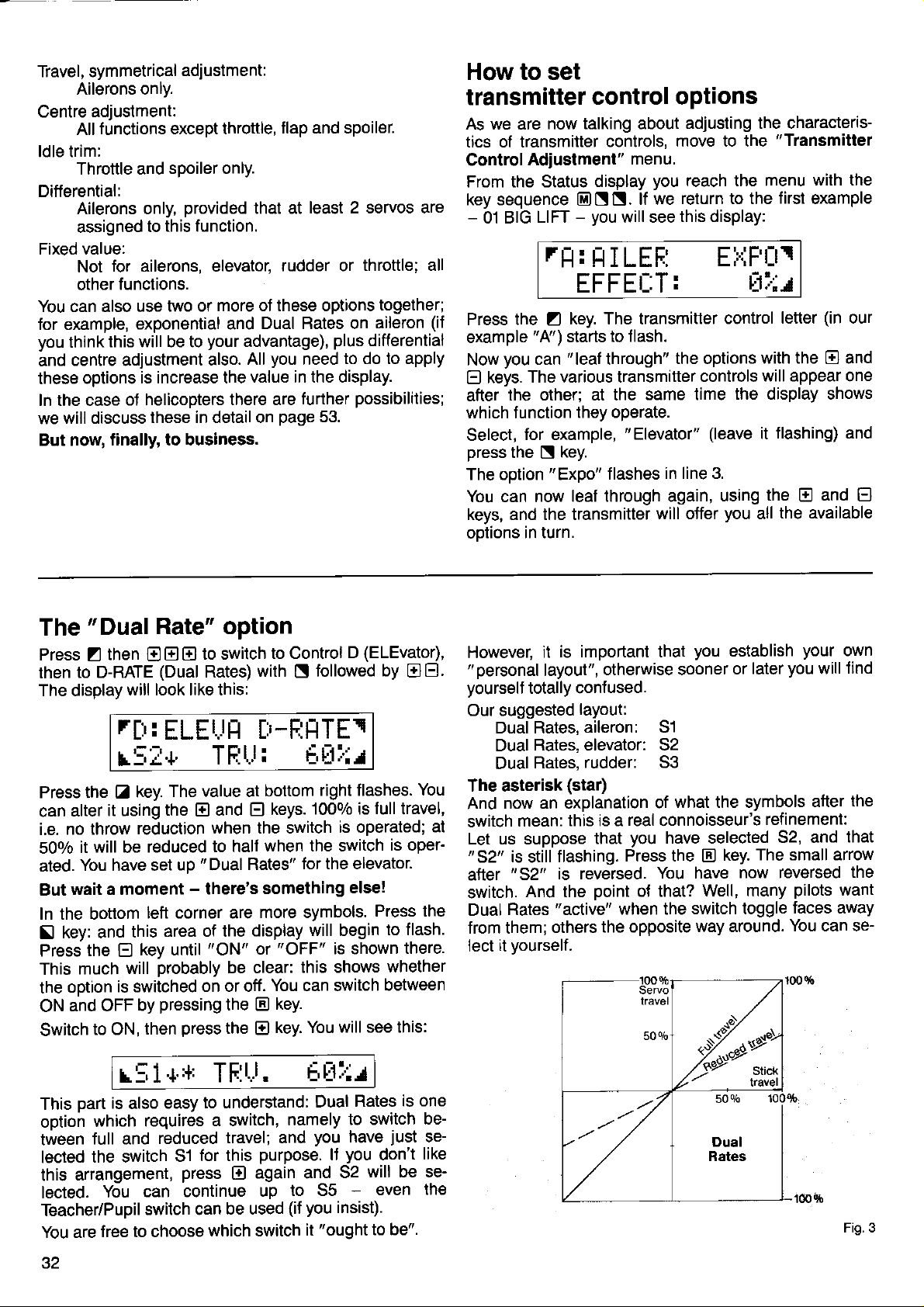
Travel, symmetrical
Ailerons only.
Centre
ldle trim:
Differential:
Fixed value:
You can also use
for example,
you
and
these
In the case
we
But now,
adjustment:
tunctions except throttle,
All
Throttle and
Ailerons only,
assigned
for ailerons, elevatot
Not
functions.
other
exponential and
this will be to
think
centre adjustment
options
of helicopters
will discuss
finally, to business.
adjustment:
spoiler only.
provided
this function.
to
two or
is increase the
these in detail on
flap and spoiler.
that at
more of these options
Dual Rates on
your
advantage),
All
also.
value in the display.
there are
least 2 servos are
Iudder or
plus
you
page
to do to apply
need
turther
possibilities;
53.
throttle; all
together;
aileron
differential
(il
How to set
transmitter
As we are
tics of transmitter
Control
From the Status
key sequence
-
Adiustment"
01 BIG
LIFT
rt:t:
control options
now talking about
controls,
menu.
display
EINN.
-
you
you
lf we
will see
HILEF:
EFFEL:T:
Press the
example
you
Now
keys.
E)
the other; at the
after
which function
Select,
press
The option
You can now
keys, and the transmitter
ootions in turn.
for example,
the
key. The transmitter
Z
"A')
starts to
"leaf
can
The various transmitter
they operate.
key.
N
"Expo"
leaf through again,
f lash.
through"
same time
"
Elevator"
flashes
will offer
adjusting the characteris-
move to the
reach the menu
return to the
this display:
"Transmitter
with the
first
example
fl:rip't_tr
E1::J
(in
control
the options
controls
(leave
in line 3.
using
you
letter
with the
will appear one
the display shows
flashing) and
it
the E and
all
El
the available
our
and
El
The
Press
then
The display
"DualRate"
then
Z
to D-RATE
will look like this:
r[:'
r5I+'
Press the
alter
can
no throw
i.e.
it
50o/o
You have set
ated.
wait a moment
But
In the bottom
key: and
Sl
the
Press
much
This
ootion
the
and OFF
ON
Switch
key.
tr
it using
reduction
will
be
this
E
will
is switched
by
to ON,
option
to switch
E E
E
(Dual
Rates)
:
ELEtJt:t
TFll.J:
The value at
the
reduced
left corner are
area of the
key until
probably
pressing
then
and
El
when the switch
to half
up " Dual
-
there's
"ON"
be clear:
on or off.
the
press
the
(ELEvator),
to Control
with N followed
D
[r-Fjt-tTEr
F-,lli:r
bottom
keys.
El
when the switch
Rates"
something
more symbols.
display
or
You can switch
E
@
right flashes.
1000/0 is
is operated;
for the elevator.
else!
will begin
"OFF"
key.
key. You
is shown
this shows
will see this:
by
OEl.
You
full
travel,
at
is oper'
Press the
to flash.
there.
whether
between
is important that
However,
"
personal
yourself
Our suggested
Dual Rates,
Dual
Dual
The asterisk
And
switch
Let us suppose
"52"
atter
swttch.
Dual
from them;
lect
it
layout",
totally contused.
layout:
aileron: 51
Rates, elevator: 52
Rates,
now an explanation
mean:
is
still
"52"
And the
Rates
it
vourself.
rudder: S3
(star)
this rs a
flashing.
is reversed.
"active"
others
you
otherwise sooner
what the symbols
of
real
connoisseur's
you
that
point
when the
the opposite
have selected
Press the
You have
ot that?
switch toggle
o/o
50
tr
Well, many
way around.
establish
later
or
The small arrow
key.
now reversed
your
you
will
after
refinement:
S2, and
pilots
faces away
You can se-
own
lind
the
that
the
want
r51+.+
part
is
This
option
tween
lected
arrangement,
this
lected.
Teacher/Pupil
You are
.tz
also
which
full and
the switch
requires
reduced
can continue
You
switch can
free to choose
TF:t"t.
to understand:
easy
a switch,
travel; and
for this
51
press
El
be used
which switch
Et:tl'lr
Dual
namely
you
purpose.
again and
up
ll
to 55
(it you
"ought
it
Rates
to switch
just
have
you
don't
will be se-
32
-
even
insist).
to be".
is one
bese-
like
the
Fig.3
Page 35
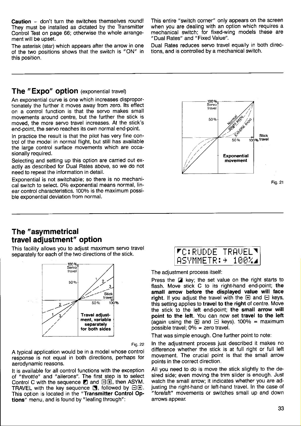
-
Caution
They
Control
ment will be uoset.
The asterisk
of the
this Dosition.
don't turn
must be installed
Test on
two
page
(star)
oositions
the switches
as dictated
otherwise
66;
which appears after
shows that
themselves
by the
the whole arrange-
the switch
Transmitter
the arrow
"ON"
is
round!
in one
in
This entire
when
mechanical switch;
"Dual
Dual Rates reduces
tions,
"switch
you
are dealing
Flates" and
is
and
controlled
corner" only
"Fixed
appears
with
for
servo travel equally
by a
option
an
fixed-wing models
Value".
mechanical switch.
on the screen
which requires a
these are
in both direc-
The
An exponential
tionately the
on a control
movements
moved, the
end-point,
In
trol of
the
sionally
Selecting
actly as described
need to
Exoonential
cal switch
ear control
ble
The
"Expo"
the servo
practice
large control
exDonential deviation
the
the model
required.
and setting up
repeat the
to
characteristics.
"asymmetrical
option
is one
curve
further it
function
around centre,
more servo travel
result is that the
is not switchable; so
select.
moves away from
is that the servo
reaches its own normal end-point.
in normal flight, but still
surface
for Dual Rates above, so
information in detail.
movements which are
this option are carried
00/o exoonential
from normal.
travel adjustment"
This facility
separately
allows
for each of the
you
to adiust
two directions of
(exponential
which increases dispropor
but the turther
increases.
pilot
there is no
is
1000/0
the
travel)
zero. lts effect
makes small
the stick
At the stick's
has very
has available
we do
means
normal, lin-
maximum
fine
con-
occa-
out ex-
not
mechani-
possi-
option
maximum servo
the stick.
travel
is
r[!
fi
FiU[i[iE
,-:r,rl'll,lETFi
TFjHtJELI
: + 1 rllr:.:r
Fig.21
A typical
resDonse
aerodynamic
It is available
of
Control C
TRAVEL
This option
tions"
application
is not equal in both directions,
reasons.
"throttle"
menu, and
for
and
with the sequence
with the key sequence
is located
would be
all control
"ailerons".
is found
functions
in
the
by
Fig.22
in a model whose control
perhaps
with the exception
The first step
and
Z
S,
"Transmitter
"leafing
then
ElE,
followed by
Control
through":
is to select
for
ASYM.
El E.
Op-
The adjustment
Press
flash. Move stick
small arrow
right. lf
this setting
the
point
(again
possible
That was simple enough.
In the adjustment
difference
movement-
points
All
sired
watch the small arrow;
justing
arrows appear.
the Z key; the set
you
stick to the
to the
using
travel; 00/o
in the correct direction.
you
need to do
side; even
'torclall'
the
process
betore the displayed
adjust the
applies to
left
left. You can now set
the
whether
The crucial
moving the üim slider
right-hand or left-hand travel.
movements or switches small
itself :
C to its
travel with the
travel to the
end-point;
and
El
=
zero travel.
One
process
the stick is at
point
is move the stick slightly
it indicates whether
value on the
right-hand end-point;
right of centre.
the small
keys). looo/o
E
further
just
described
is that the small arrow
right starts to
value will tace
and
El
arrow
travel to the
=
maximum
point
to note:
it makes
full right or
to the de-
is enough. Just
you
In the case
up and down
the
keys,
El
Move
will
left
full left
are ad-
no
of
Page 36

The
"symmetrical
travel adjustment"
option
This option is only available
ment facility
sense
fect would be the same as
olied.
you
lf
scribed above,
f
unction;
Here again:
for
both sides separately
here; with two differential aileron servos the ef-
have already tried out some ot the options de-
you
will have no trouble setting up this
it is carried out in exactly the same
1000/o = maximum
for
if
ailerons.
difterential
travel; 00/o
A travel adjust-
would make no
had
=
been
way.
no travel
ap-
Fig. 23
The
This is available
shift the centre
tronically";
trim sliders.
The maximum
enced
same
sliders).
The adjustment
end-point
The adiustment
Move to
transmitter control
press
D:ELEV"
with the
ing). You
"Centre
for most
position
has roughly
it
travels which
by the centre adjustment
way
as
of the corresponding
the
the Z key and then
appears.
El
will then see this:
"centre
the
range is up to
procedure
"Transmitter
key until
Trim"
D = Elevator as an
Press the S key and
"Centre"
option
control
of the transmitter control
the same effect as
trim" system used by the trim
Options"
functions. lt is used to
you
have set are not influ-
(i.e.
it works in the
1000/0, i.e. as far as the
transmitter control.
is
simple:
menu. Let's look at
leaf through until
appears
in line
"elec-
moving the
Fig.24
example.
leaf
"Ctrl
through
(flash-
3
First
Press the
flash. You can carry out the centre adjustment
want, using the E and
pleted
the
E
Here
are two
tor
this option.
Example 1:
You have seen that it is
1000/0, i.e. to
up to
extreme setting
associated servo
moved to one side.
the servo carries
This facility could be used for a
the brakes are extended
moved back
'lorward'
spond
full servo travel controlled by
Example 2:
With a well-built and carefully trimmed
tion of the trim sliders
only very slightly.
sliders as
the trims
alter
ting of the trim sliders
tion.
Caution: do
facility to
provided
key;
Z
the
adjustment,
key.
more
from the centre
hal{ of the stick travel
at all, and stays at
perhaps
your
when
not
"centre
for this
value
the
examples ot
one end-point.
-
in this example for one stick axis the
does not move at all when the stick
When it is moved to the other side
out its tull movement.
the most common application!
you
lf
centre adjustment,
you
use the
servos". There
up
(see page
displayed
keys.
E
return to the Status display with
possible
when the throttle stick
position.
full movement. You now have
half the stick movement.
is not
usually changed
adopt the
change
is
then always
transmitter control centre trim
29).
at bottom right will
you
Once
typical applications
to offset
you
It
glider
the
servo
position
you
models; the basic set-
is
a separate
have com-
the
centre
select such an
with
airbrakes:
Over the entire
does not re-
model the
in flight, or
of the
will not need to
the centre
facility
you
posi-
trim
posi-
by
is
is
34
r[r
:
ELEl.Jtl
t_:E[.lTFlEr
TEIf'l:
+11:r
Page 37

The
This option
trol
tle stick
its
the centre
throttle
throttle"
"ldle
function
trim slider
"idle"
position.
position
"half"
end-point)
is only available
Trim" option
(or
THROTTLE-2).
is only effective
stick
is
arc
lts effect
of the stick.
the
of
the trim slider has
for the
"THROTTLE"
lts effect is that
when the stick is at
steadily
reduced towards
In the whole of the
(especially
no
ldle trim
at
effect.
Stick
con-
the throt-
full-
"full
the
Fis.25
practical
The
adjust the
lull-throttle
ing its
Selecting
advantage
idle setting of the
position.
and adjusting
the other options already
Adiustment
0/o
0
range:
in the display:
oJ this option
carburettor
this option
described.
"throttle"
the
effect.
"throttle"
100 % in the display:
the
the idle
whole of
arc.
practice (special
In
is a sensible sefting.
300/0
further note:
One
Normally the
back". lf
copter),
idle
you
want
press
This reverses the entire stick
ward". This is
(-)
in lront of the set value, instead of a
the
then rotates
servo
as described on
cases excepted) a
position
it
y
the
the
of the throttle stick
other way round
key once at the adjustment
function; idle is then
indicated in the display by a
page
28.
in
wrong direction,
the
is that
you
without
is
the same
trim slider
trim slider
position
within the
has no
adjusts
one halt of the stick
value of 20 to
is
(e.9.
for a heli-
minus
plus
sign
reverse it
can
aftec!
as for
"stick
stage.
"for-
sign
(+).
lf
The
This option
been assigned
the
been
makes
"Asymmetrical
"Differential"
is only available if a transmitter control
"Assigning"
assigned
no
to the control
stage, and
"aileron".
to
sense,
or can be
travel adjustment".
t*=
To explain
The
signed
Transmitter control
ATLERON; servo 5
Starting
ter Control
leaf through
play,
how this works,
transmitter controls and
as follows:
=
from the Status Display,
Adjustment"
with
f lashing:
rH:
until
El
I I
HItit'l1'lETF:
option
function
if
least two servos have
at
In all other cases
replaced
50
\\
\'.\-
\so&
Difter.ntial
we will
=
A
AILERON
menu. Press the
you
take another
servos have been as-
AILERON; servo
move to the
see
"AILERON"
differential
the option
by
0,6
1(
^
\'.{;
'(
"Transmi!
"DlFFER."
N
example.
in the dis-
LEF: ['I FFEF'I
! +Ir:rlir
Fig. 26
key
has
1=
and
It is vital that the servos
at
erwise the differential
(see page
Press the
You can
using the
26).
key; the value at bottom
Z
now
E)
the degree of difterential
set
and
E
The f igures mean:
0/o -
0
no ditferential; same
lor both servos.
5O
o/o -
"down"
the
as the " uD"
1oo
o/o -
maximum ditferential: each aileron
but does not move down at
You don't need to
worry about anything else
ting up ditferential.
to the two servos automatically.
sent
When setting the degree ot
verse" the differential
You will
ailerons correctly,
ing this option
servos
lines, however, as
in model design
One
It is
find that it is
in conjunction
(see page
and radio installation.
more tip
sometimes
(which
easier and
regardless of
28). We
there are so
right settings by carrying
This is very
as an accessory:
able
Before
as
starting
already described, and select
scribed above; but
using the Digi-Adjustor,
easy
a flight,
this time don't leave the
are assigned correctly, oth-
movements
will not be correct
right will flash.
you
keys.
movement up and down
movement
is
half as large
only
movement.
all.
The differentiated
difterential
with the
possible
control signals are
you
key.
El
to set up differential
your
installation, by us-
with reversing one or both
cannot
also applies
quicker
give general guide-
possible
many
to other adjustments):
to find exactly the
out " in flight" adjustments.
which is avail-
move to the appropriate menu
"Adjust
Value"
menu!
require
moves uo,
when set-
"re-
can
variations
as de-
35
Page 38

Digi-Adjustor
The
and
adjusting
this
flying
Land
E]
nothing
keys, and
El
the degree
is to rotate the
case
(don't
the model,
(everything
key
more to be done).
is connected
has exactly
of differential.
Digi-Adjustor
look down at
then leave
gets
"in
parallel"
the same effect,
All
it!) until
stored
you
the menu by
automatically
with the
namely ol
you
need to do
while the model
satisfied.
are
pressing
-
El
in
the
there's
Caution!
Although
never aitempt
is
model is
the
the model
off
mistake, the
it is theoretically
make changes
to
flying. You
to find the
results could
would have to take
right key; and
be catastrophic!
possible, you
via the
keypad while
your
you
if
should
eyes
made a
The
what's
"Dual
iar to
close
The simplest
examore:
lmagine a
operated
Travel
that
grees
to use
ness
NoW
degrees)
ation
move
return to
In order
switch
that the
This
"Fixed
set
ated.
There
First, of course,
travel).
Second,
Value
Adiustment
scribed
Here
We will assume
follows:
Transmitter
This
connected
You
"Fixed
that?
Rates",
the advanced
terms with
model
by the
has been reduced
full flap movement
at the two
"Fixed
of the option).
on this
which is only
(say,
flaps to this fixed
the
normal operation
to achieve
to override
flaps take
is what
Value"
value when the
fixed
and overrides
are therefore
the switch
has to be
above
is another example:
means that
Move
Select
press
to the
Transmitter
rhe
N
will now
Value" option
"Exponential"
"Fixed
method of explaining
with
right-hand slider
slider end-points
Value", but
model there is a specitic
launching).
"Fixed
moves the control
selected.
is carried
for
that
control
the
to receiver
"Transmitter
key; rhen
see this
rF:t:tl_liri.
rrJFF
Fixed Value
Selecting
the
and so on are
modeller.
Value",
camber-changing
is in the
needed for a
Wouldn't
this it
"normal"
the
pre-set,
up a
Value"
the transmitter
tlvo things
the Fixed
which
out in a similar
"Dual
Rates''.
you
=
F
right-hand slider
output 6
Control
s
display:
He may not be on such
however.
=
(using
have assigned
AUX.I;
the
range
(this
it
does
it be nice
position
again afterwards?
would be necessary
flap control
fixed value.
is
about.
all
associated switch
to set up:
Value itself
"activate"
is to
gsrvo
control
F, d;:i.^"'"""'
"g;,
un,ir
1 FII:-1r
switch:
-
terms Jamil-
it is to describe
flaps which
transmitter
"Travel"
is not necessary
show up
Jlap
particular f light situ-
with a switch, then
function
control
way
g
controls
Adjustment"
control
option)
-5
to
the useful-
position (+15
if we could
signal, so
to a
itself.
o/o
(in
the
to that de-
the controls
=
AUX.1. this
the servo
"Flx-1"
an
are
so
+75 de-
for lhe
pre-
is
oper'
full
of
Fixed
as
menu.
appears
Stlli:,r
ln our examole
key; the display
probably
It will
turns to
Leaf through
you
the switch 55;
F.
must
Adiusting
Press the
hand corner
You can
El
other end-point.
750lo
one
Now
"Fixed
the servo
slider.
you
lf
roünd",
the
and
also
lmportant
When
ticed
can,
Fixed
For example,
camber-changing
"
SDeed".
In order
special
control
(nothing)'
lf-your brain
time
"ON".
will see an arrow
appear.
the Fixed
Z
now adjust
keys. 00/o
this means a
end-ooint.
you
can carry
Value"
can be controlled
When set to
just
have
now
vou
press
key, and
E
you
will find that
reversed.
note
"leafing
that there
fact, set up
in
Value-2)
to exploit
3-position
purpose,
Jor normal
More
present
to
this is to be
in the bottom
show
the E key until
with
and
at one
This means that
Value:
key; the
to flash.
starts
the'Fixed
means one servo
For
position
out a
function works:
"On"
set.
want the switch
the
S
the arrow
the direction
for F3B flyers:
through" the
further option
is a
two
which
you
you
is slill
you
could
flaps on a
this option,
switch
must not assign
usage;
on this on
lunctioning
further reJinement
a
the switch 55.
"OFF".
of the two
value shown
example,
key again;
"Fixed
left-hand
Press
"55"
possibly
positions
the switch
Value"
end-point;
you
if
half-way between
practical
when switch
in the normal
the servo
work the
to
"S5"
"S5"
after
options
Values"
select at
can
set up
two
you
"S1".
i.e' Icontrols
you
lf
page
69'
clearly'.
the
an asterisk).
in the bottom
test
runs
of switch
"Fixed
pre-set
glider:
will need to use
of this transmitter:
äffi'H:1'iT"Ut["i,n:t".ofi':llj]tt"flöt
toni,-insteäO
"stick
tary
stopwatch.
In the
momentary
press-button"
switch
lollowing
äiä
which
switch
noimat toggie
is one
is recommended
we assume
of this
type to
switch.'
example, or
you
that
"S4".
Press the
corner
set the
will flash.
will be
you
(Fixed Value and
will.
use the switch
it as
will flash.
key;
tr
appears
the asterisk
is set to
with the
1000/o the
centre and
to see how the
55 is
way with the
to the
"other
reversed'
actuation
have no-
may
Value-2".
positions
"Tow"
a transmitter
=
""
this is a
Sl
"OFF"
(after
Operate
"ON".
right-
and
El
value to
"Off",
position
way
Press
You
for
and
the
I for
good
ilJSffil
Th'e optionat
momen'
the
for operating
have connected
the
it
is
a
36
Page 39
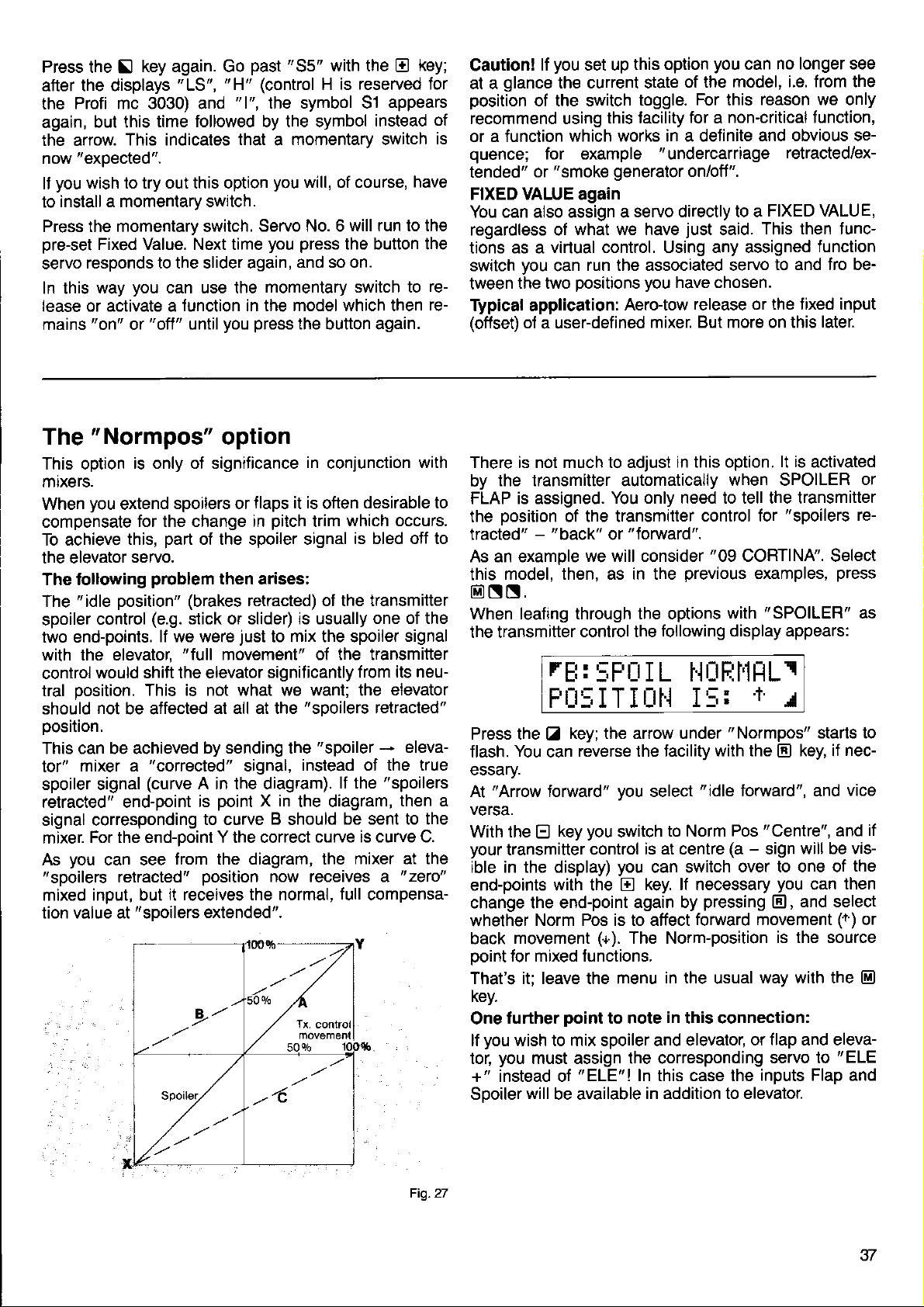
Press the
after the displays
Profi mc 3030) and
the
again,
the arrow.
now
lf
to
Press the momentary switch.
pre-set
servo
In this
lease or activate a
mains
but this
"expected".
you
wish to try out this option
install a momentary switch.
responds to the slider again,
"on"
key again. Go
N
This indicates
Fixed Value. Next time
way
or
"LS",
time followed by the symbol
you
can use the
function in the model which then
"off"
until
past
"H"
"1",
that a momentary switch
Servo No. 6
you press
"S5"
with the
(control
the symbol 51
you
you press
momentary switch to
is reserved for
H
will, of course,
the button the
and so on.
the button again.
E
appears
instead
will run to the
key;
of
is
have
rere-
you
lf
Caution!
glance
at a
position
recommend using
or a function
quence;
tended"
FIXED VAUE again
You can also assign a
regardless of
tions as a
switch
tween
Typical application:
(offset)
of the switch
or
you
the two
of
set up
the current state
this tacility
which works in a delinite
for example
"smoke
virtual control. Using any assigned
can
a user-defined
generator
what we have
run the associated servo
positions you
this option
toggle.
"undercarriage
servo directly to a
Aero-tow
mixer. But more on this
you
can
of the
just
have chosen.
model, i.e. from the
For
for a non-critical f unction,
on/otf".
release or the tixed input
reason we only
this
and obvious se-
This then func-
said.
no longer see
retracted/ex-
FIXED VALUE,
function
to and fro be-
later.
The
This option
mixers.
When
compensate
To achieve
the elevator
The following
The
spoiler
two end-points.
with the elevator,
control
tral
should
oosition.
This can be achieved
tor"
spoiler signal
retracted" end-point
signal corresponding
mixer.
As
"spoilers
mixed input, but
tion value at
"Normpos"
is only oJ significance
you
extend
"idle
position" (brakes
control
would shift the elevator
position.
not
be affected
mixer a
For the end-point Y the correct
you
can see
retracted"
spoilers or
for the change in
part
this,
servo.
problem
(e.9.
This is not what we want; the
"corrected"
(curve
"spoilers
of the spoiler signal
stick or slider) is usually
lf we were
"full
at all at the
by sending the
A in the diaglam).
point
is
to curve B should
from the diagram, the
position
it receives the normal,
extended".
Spoilet.
option
in
conjunction
flaps it is
pitch
trim
then arises:
retracted) of the transmitter
just
to mix the spoiler
movement" of the transmitter
significantly from
"sooilers
signal,
instead of the true
X in
the diagram,
curve is curve C.
now receives a
desirable to
often
which occurs.
is bled olf to
"spoiler
lf the
be sent to the
mixer at the
full
compensa-
,.4
with
one of the
signal
its neu-
elevator
retracted"
-
eleva-
"spoilers
then a
"
zeto"
There is not much to adjust
the transmitter automatically
by
FLAP is assigned.
the oosition
tracted"
As an example
model, then, as in the
this
@NN.
When leafing through the options
the transmitter
t'back"
-
rEt
You only need to tell the transmitter
of the transmitter
control the
"forward".
or
we will consider
:
:;Fü
FIJ:;ITIÜH
Press the
You
flash.
essary
"Arrow
At
versa.
With the
your
transmitter control
ible in the display)
end-points with the
change the end-point
whether
movement
back
point
for mixed functions.
That's it; leave the menu
key.
further
One
you
lf
wish to mix spoiler and elevator,
you
tor,
+" instead ot'ELE'I
Sooiler
key; the arrow under
Z
reverse the facility
can
forward"
key
E
Norm Pos is to affect
point
must assign the corresponding
will
be available
you
you
switch
you
E
(+).
The Norm-position
to note
in this option.
when SPOILER
control for
"09
previous
with
following display appears:
I L f.luFjlitlLl
I5:
"Normpos"
with the
select
is at centre
can switch
key. lf necessary
again by
In this case the
in addition to elevator.
"idle
to Norm
(a
pressing
forward movement
in the
in
usual
this connection:
lt is
activated
"spoilers
CORTINA". Select
examples,
"SPOILER"
T
1
El
forward", and
"Centre",
Pos
-
sign
over to one of
you
El,
is the source
way with the
or flap and eleva-
servo to
inputs Flap
press
starts to
nec-
key, if
vice
and
will be vis-
the
then
can
and select
(r')
"ELE
and
or
re-
as
if
or
E)
Fig.27
37
Page 40

lhe
How to use
"Com$-8vvitch"
The main use of the Combi-Switch
pilot
experienced
model
ouire co-ordinated control ol
der to
simultaneous control
lems,
The Combi-Switch
trols electronically.
on
switch between
coupled controls at any
You can choose
works:
or
The
preference.
"following"
A turther
"following
and
An explanation:
At a following rate of 500/0 the slave control
deflect
full throw. The only
from the
stick.
At a
to the same
At a following ßte
flects to
onlv at
this ooint.
extent;
cause there's
glider.
fly
a smooth turn
especially
and otl via a switch, so that
rudder follows
The
operate both controls with the aileron stick;
The ailerons tollow the
ooerate both controls with the
mode which
point
20oo/o.
to half its
following control surface
following rate of 1000/0 both control
its full
haltthrow. It the master stick
the master conlrol surlace
the slave control
o/o
50
handle the more
For aerodynamic reasons many
rudder
-
just
like the full-size. However,
of two functions can
for the less
is
The coupling can be be turned
"normal"
the way in which the coupling
you
In both cases
"slave")
(or
which needs
rate". lt can be set to any
full
travel
way
extent.
ol 200o/o the slave control
extent
no more movement available.
when the
practised pilot.
to
used
(separate
time in flight.
the ailerons;
rudder; in
choose is a matter of
you
f
unction
when the master control
getting greater
of
surface stays at
100 Vo
is to helD the less
demanding
and ailerons
present prob-
couple
retain full
via its own stick.
explanation
master
these two con-
possible
it is
controls) and
in this case
this case
rudder
is
stick.
control
point
to operate
surfaces move
control
is moved bevond
moves to
tull throw - be-
2OOo/o
\l\l
\t\l
flF
\\\
master slave
It is very difficult
as the
in
test
This is an
you
flight.
ideal following
doubt,
you
flights to find the best
ideal case for using
can then
\/\/
fln
\\
master
for us to make
rate varies from
with 1000/o
start
could
setting for smooth,
easily adjust
nq
\\
slave
recommendations
the tollowing
master slave
model to model. lf
then carry
and
the Digi-Adiustor,
forms of
gliders
here
between
surface will
movement
surface de-
surface
tidy turns.
re-
in or-
to
you
you
personal
of the
is
the
0
is
at
its own
is
it; full
Fig.28
here,
out
as
rate in
Now,
after this
hand:
You cannot set up the Combi-Switch until
ready assigned one transmitter control
one to
the
display
We will take as our example
You will find the soecial Combi-Switch
"
From
key sequence
see this display:
rudder. You will
function
is
already
Transmitter Control Adjustment".
the Status display
necessary
(e.g.
S5).
marked CS = Combi Switch.
Then
Eltr.
r
tilt_iij r_::,['J:
l
FlUtitiEFj
"55+"
bi-Switch. Press the
the
switch. lf
tion that appears
comes
indicates
and E keys
El
you
continue
"OFF".
r
that switch 55
N
is
Now the Combi-Switch
1t:1r:i:i [:11.il
E:Llt:'[1EF:
As we don't
("ON"),
The + arrow after
i.e. the controls
the direction
press
the
eration of the switch.
'l
arrow turns
Incidentally:
asterisk
you
Now
rudder the slave,
Press the Z key; the
press
you
lf
ternates
"AILERON
work. In our examole
to
governs
you
Now
the appropriate
leased", simply set the
keys, or the Digi-Adjustor;
In the display
want that at the moment,
then the E key, until
"35"
are coupled
of the arrow.
y
key now; this reverses the direction
into a r arrow.
when the switch
appears after the arrow
can select
the
between
governs
RUDDER",
have to set the value
you
r
whether aileron
or vice
key,
E
"RUDDER
RUDDER".
i.e. the aileron control
input
should
t1tit:.:
l
F:l_t;:'X,gp'
That's all there
key.
@
is to it:
preamble,
need to install a switch for
also
The
switch
"06
you
reach this menu with the
press
+f;
is selected as the Com-
key,
and
you
pressing
"ON".
can
Press
now
the
+H
"55+ "
indicates that the switch
-
if
you
lf
In the display
is in
in confirmation
versa.
following rate value starts
the bottom
governs
we will leave it at
for
field is already flashing,
you
value
in our example
see the
t_:5lr.l:
+tl
you
leave the menu with the
can
to the matter
to ailerons and
well on the left of the
FIESTA'.
menu
go
to
S
:,i+.
r
I LEFjr:rt.,l
"55+"
!
[tFF
flashes. Using
select
key the final op-
El
and
El,
is out of
r
I LEF:r:rt]
press
appears again.
you
move the switch in
wish to
you
will see that the
the ON
is
to be
line of the display
AILERON" and
Leave it as
is
following rate: as
the
with the E or
want
1000/0.
following:
:,i.+.
1
I LEFIüH
you
have al-
under
on. You will
a different
"ON"
reverse
position,
master and
you
"AILERON
the
be-
circuit:
again
El
is
on
this,
of op-
an
(++).
to flash.
aF
want
master.
"re-
i.e.
El
in
-
it
38
Page 41
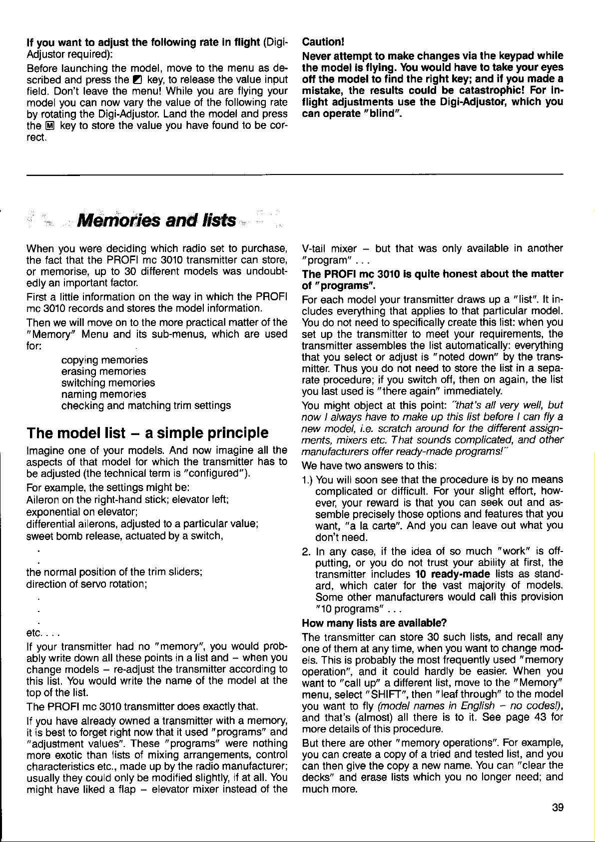
you
lf
Adjustor
Before launching the
scribed and
field.
model
by
the
rect.
want to adiust the
required):
press
the Z key, to
Don't leave the
you
rotating the
key to store the value
@
now vary the value of the following
can
Digi-Adjustor. Land the model and
following rate in flight
model, move to the
release
menu! While
you
have found to
the
you
are f lying
(Digi-
menu
as de-
value input
your
rate
press
cor-
be
Caution!
Never attempt to
the model is
off the
mistake, the results could be catastrophic!
flight adjustments use the
can operate
model to find the right
make
changes
flying. You would have to take
"blind".
via the
key;
Digi-Adiustor, which
keypad while
you
if
and
your
eyes
made a
For in-
you
Msmoäes and
When
the fact that the
or memorise,
edly
First a little information on the
mc 3010 records and stores
Then we
"
for:
The model
lmagine one
asoects
be
For example,
Aileron on the
exoonential
differential
sweet
the normal
direction
elc....
lf
ably
change
this list. You
too of the list.
The
lf
it is best to
"adjustment
more exotic than
characteristics
usually
might have liked a
you
were deciding
PROFI mc 3010 transmitter can store,
up to 30 different
an important
will move on to the more
Memory"
copyrng memones
erasrng
switching
namrng memofles
checking and
factor.
Menu
and
memones
memories
list
your
ot
of that model
ad.iusted
your
write down all these
PROFI mc 3010 transmitter does
you
(the
technical
the settings
right-hand stick; elevator
on elevator:
ailerons, adjusted
release, actuated by a switch,
bomb
position
of servo
transmitter
models
would write the name of the
have already owned
forget right now that
values".
they could only be
of the trim sliders;
rotation;
had no
-
re-adjust the transmitter according
lists oi mixing arrangements,
made
etc.,
flap - elevator mixer
which radio
the model information.
its
sub-menus,
matching trim settings
-
a simple
models. And now
for which the transmitter
term is
might
to a
"
memory",
points
a transmitter
These
"programs"
up by
modified slightly,
#$b
purchase,
to
set
models was
way in which the PROFI
practical
which are used
principle
imagine all the
"configured").
be:
left;
particular
you
in a list and
exactly that.
with a memory,
it
the radio manufacturer;
"programs"
used
undoubt-
matter
value;
would
-
model at the
were nothing
if
at all.
instead ot the
of
has to
prob-
when
control
the
you
to
and
You
V-tail mixer - but that
"program"
The PROFI
"
programs".
ol
For each model
cludes everything
You do
set up the transmitter
transmitter
you
that
mitter.
procedure;
rate
you
last used
might object at this
You
now I always
model, i-e. scratch around
new
ments, mixers etc. That sounds complicated,
manufactu rers offer ready-made
We have two answers to this:
1.) You will soon see
complicated
ever,
semble
want,
don't need.
2. In any case,
putting,
transmitter
ard,
Some
"
10
How many lists are available?
The transmitter
one ol
This is
els.
operation", and
want to
menu, select
you
want lo
and that's
more details of this
But there are other
you
can create a
can then
decks"
much more.
. . .
mc
3010
your
not need to speciJically create this
assembles the
select or adjust
you
Thus
your
"a
which cater for the
other manufacturers
programs"
them at any time,
"call
give
and erase
do not need to store the
you
if
"there
is
have to make up
or difficult.
reward is that
precisely
la carte".
iJ the rdea of so
you
or
includes 10 ready-made
. . .
can store 30 such
probably
it could hardly be easier.
a different
up"
"SHIFT",
(model
fly
(almost)
copy of a tried and
the copy a
was only available
quite
is
transmitter draws up a
that applies to that
to meet
switch
again"
that the
those options and
And
not trust
do
the most frequently used
then
all there
procedure.
"memory
lists which
honest about the
particular
your
requirements, the
list
automatically:
"noted
is
point:
For
you
you
when
list, move to the
"leaf
names
new name. You can
down" by the trans-
off, then on again, the
immediately.
"that's
this list before I can fly a
for the
programs!"
procedure
your
slight effort, how-
seek out and as-
can
leave out what
can
much
your
ability at
vast majority of models.
would call this
lists, and recall any
you
want to change
through"
in English ' no codes!),
is to it. See
operationst'.
tested list, and
you
no longer
in
"list".
list: when
everything
list in a sepa-
all very well, but
different
and other
is
no means
by
features that
"work"
lists as stand-
When
"Memory"
to the model
page
For
"clear
need;
another
matter
lt in-
model.
you
list
assign'
you
you
is off-
first, the
provision
mod-
"memory
you
43 for
example,
you
the
and
eo
Page 42

We don't
We
what
and
gram".
Now, it
"copying
store
enough.
not exactly
Joking
But
rect style
Everything
particulär
a
contained
the
different
Are
sionally
interchangeably.
one
most appropriate.
sionally
why, and
your
of
One
The
are
mind
have used
the transmitter
because
has become
memories".
even one
Copying
aside: everybody
we think
of thinking
contents
memory, and
we splitting
use
term,
sound
can always
mind.
important
model
actually
the
list is easier
a
model
the
a simple
it is worthwhile
the transmitter
that
model
in a memory.
of the
hairs?
the terms
In this
sometimes
However,
less than
point
which is shown
tlying,
is the
you
i{
to use the
want
"list"
word
actually
usual to
In fact it would be
memory chips
job,
when dealing
is included
memory
keep the
to
assembles
talk of
in a transmitter
either.
knows what
cultivating
When a
which are duplicated
so on.
We have to admit
"list",
manual we sometimes
the other,
if the
precise,
remember:
in the display,
"current"
ordinary
here, because
for each
to imagine
"storing
pretty
-
in the transmitter
the terms
a clear
with this
"needs
in a list, and
memory
"memory"
depending
then
idea of the
to know"
"sloppy"
you
model.
terms.
is
that
model,
than a
just
it
is copied,
that
and
terms
at least
list in the back
and
"pro-
models"
difficult
equipment.
the list
we occa-
"model"
on what
which
or
to
ain't big
is
mean.
and cor-
about
is
it is
in
a
the
use
is
occa-
know
you
you
lf
travel,
ways recorded
cally,
therefore
When
matically
expressly.
most
strains
But take care
Let us
and
to risk
Nevertheless,
experiment
Or
want
What to do?
Well, the solution
into a
memory and experiment
This also
While
should
and
For this
most
pler
make any
to mixing
immediately.
always
you
switch
restored,
We have
natural method
the old
imagine that
trimmed
making any
perhaps you
to use the same
different
applies
you
always
not
on
reason
important things
you
than
changes
ratios etc.),
in the
grey
-
it out
you
-
but
are unfamiliar
work on
"genuine
the
might think!
list
When
"uP
on again,
i.e.
there could
would
this
have built
to the
memory,
to the
"copying
you
to date".
you
found that
working, and
of
cells the
you
have test-flown
great
with
lurther changes
like to try something
would change
with minor
list,
problem
to
copies of
originals".
to
(e.9.
to the trims,
modification
the
then
"current"
(the
switch off,
"latest
this
need to store
never
is the easiest and
this
the one
least.
be a catch!
You would
care.
to this
your
a new, similar
modiJications.
is simple: copy
"shift"
then
your
heart's content.
"ready-made"
with the transmitter,
the original
memories"
learn at the start.
to servo
list) automati-
the memory
state"
is one of
is auto-
anything
a new
not want
"ideal
out as
hard-won
model, and
to the
sample
lt's sim-
is
al-
is
which
model
list".
an
list.
list
the
new
lists.
you
lists,
the
The
All the tasks
from the
reach
You will
"Memory"
connected
"Memory"
menu with the
this
see this display:
r[:[rF
t5H
you
here
From
Keys:
Copying
The term
memory
translerring
Naming
This allows
the
shifring
This
whose
Z:
"copying"
to another,
N:
list.
!:
is where
you
list
a
you
Menu
memories are carried
with
menu.
ti
I FT
select
list from one transmitter
enter or
to
you go
have already stored.
From the Status
key sequence
HHt'lEr
I]HFi.
the Jollowing
covers the
but also
modify the
to switch
TFI I I'1r
points
actual copying
related tasks,
to a ditferent
@ f)
to
model's
out
display
.
with the arrow
another.
you
one
of
such
name in
model
Trim
Z:
From
tion of the
time".
memory
you
Atter
matically,
moved since
Naturally,
ing memories.
transmitter
sliders
you
as
last switched
For example,
moved, but
These
below.
this sub-menu
trim sliders
More accurately:
shift
it is very
as
the last time
you
can
there
are still
if
you
four sub-menus
you
since
memories this
likely that the
also call
normal use,
In
is no automatic
at the
you
are not
position
off, so this
think
quite
are explained
check
can
has been
the last time
menu
you
up this
is a useful
that they
sure.
the
used
menu without
when
check
where they
whether the
moved
is called up auto-
you
since
you
trims
"new"
switch
that the the
were when
feature.
might
greater
in
posi"
last
this
used
have been
memory.
switch-
on the
trim
have been
detail
40
Page 43
The
From the Status
Menu
there
see this:
"Copy"
with
the
to the
"Copy"
key
Menu
Display
Menu with the Z key. You will then
you
reach
sequence
@S,
"
the
move from
and
Memory"
"Mode:"
the simple copying
later. At the moment we will only discuss the
copying
is the route to several
procedure.
process,
which is used
possible
We will discuss these
most frequently.
variations from
"normal"
rl'lü[iE
:
FULL
rFF:f'l. 15: El'l 1 1i
How to copy a
Here we assume that
Menu, as described above, and that the display
shown above.
tirst line
The
oornI.
The second
number
to copy. The transmitter suggests,
knowledge,
We will assume that
model
Press the N key; the memory number begins to flash.
You can now
or
This defines the
E
"BlG
keys,
(Mode:
line
name
and
the
LIFT" in memory No. 10.
"leaf
the Digi-Adjustor,
or
rIiUIlE
LFFjt'l. I
press
Now
flashing. You have now copied this list into the currently
active
Caution: all copying
currently active
Press the
now resides
the usual
Here is the whole
the
memory.
key
@
in the
way with the @ key.
model list
you
are already at the
ALL)
shows the
the model list which
of
"current"
through" the memories using the
"source".
model.
you
want to copy a model; e.g. the
The
:
t:'r :
key,
El
memory
and
and
procedures
you
are
current
procedure
not interest us at this
does
"source";
in
BIG LIFT appears.
until
display
namely
you
lack
the
looks like this:
FULL
rjl
E I
the
done. A copy of BIG LIFT
memory. Leave the menu
again
I FT
source
always
in brief:
memory stops
copy into the
"Copy"
is
as
the
want
of better
El
in
The
destination
copy is to be located) is always the current
memory).
Select
copy) in line 2. Press the
makes the
Note:
As
"delete"
Two more
Tip No.
On
cide not to copy anything, in spite of being at the
"Copy"
no vacant memory). You cannot
without doing anything, since
leave the
What to do?
There
The first: select as
then
on top of
Or
Tip No. 2
Let
copied a
overwritten the list stored there. Now
it's not a disaster. Please see
cue solution
the
copy.
you
have seen in the example,
the
tips
1
occasion
Menu
menu would
two ways out of this
are
press
the @ key. You have then copied the
itself, which means that nothing has changed.
the second:
us assume
list into the wrong memory, and have thus
(the
memory No. where the new
(the
source
L€ave the menu with the
"destination"
you
may have second thoughts, and de-
(1or
example,
just
switch off the transmitter.
that
(Memory
model which
key; the transmitter
El
memory
execute the copying
"source"
you
notice too late that
"
Mx").
before
you
may find that
just
pressing
problem.
the current memory, and
page
you
you
do not need to
you
leave the menu
the k key
you've
42 lor the final res-
want to
key.
@)
copy.
is
there
to
procedure.
model
you
have
it! But
done
How to erase
you
lJ
confusing
cant,
This is not absolutely essential, as
enter
contents
mind
unseen
prise
For this reason the transmitter offers the ootion of eras-
ing the contents
"Copy"
Here is where the
line we skipped earlier on.
are creating a
route is usually to
or emply.
when
assigning
of the memory in any case. However, bear
that some aspect of the
in the new
inopportune moment.
at an
memory.
a memory
"new"
list,
of a memory. This is done from the
line
list, the
pick
and adjusting overwrites the old
previous
it
and
could
"Mode: "
simplest
a memory which
everything which
model might lurk
give you
comes
and least
a nasty sur-
play
into
is va-
you
in
-
the
We
shall assume
Press the Z key, and
press
Now
controls)
into
appears. Press the
"ERASE".
that
the
key,
El
This is the mode
r[''lt_t[:rf
rFF:l'1.
press
Now
erased.
Note:
The erasure
memory.
tive)
the
Press
@
process
key, and the current
El
again to
you
are still at the
"ALLi'
on the
"CONTROLS"
and
key again, and
El
which we now need:
'+'EFiHIE
Ef,tFTtj
leave the menu.
always
works on the
right
"Copy"
starts to
menu.
(transmitter
it
memory is
current
flash.
turns
(ac-
41
Page 44

The
copying
Earlier on
copy
assignments and settings
servos,
As
the
"CONTBOL"
lf
signments and adjustments of the transmitter controls
are copied
not cooied.
The
Many
rangement of the transmitter controls, which they use
"TRANSMITTER
CONTROU'
mode
in
this Copying section
mode. This simply copies the entire
of transmitter controls and
into the new memory.
you
have already seen
"
ERASE' mode,
mode. This is
you
select the
reason for this mode:
pilots
"CONTROII'
into the current memory. The
have a
when
there
easily explained:
"standard"
we used the
you
is
also
copy mode, only the as-
assignment and ar-
"list",
leafed
through
(transmitter)
the
"servo
"ALL"
i.e.
all
to
side" is
for
only the servo arrangement is different,
this copying
adjustment
the
with many
It is never
could
and adjust
scribed earlier in this manual.
It is not necessary
TROLS". Apart trom the fact that
TROLS" tirst. the
when copying
every
more
just
model. lf
mode instead
procedure
complex
control
absolutely essential
as easily spend a
your
you
acquire a new model, in which
you
the normal assigning and
of
for
models
surfaces), this can save time.
transmitter controls step by step, as de-
to describe
Drocedure
"ALIJ'.
transmitter controls. For
the
(e.9.
helicopters, or models
to
little more time and assign
how
is exactlv the same as
this mode;
use
to copy
you
select
can use
"CON-
the
"CON-
you
The
copy
These two
fer
details
Note:
PORT
The
the
When
have come across
memories:
l there
However,
permanently,
tered" by the transmitter
1)
2) When
3)
And the
Well, the first case
take and erase
chance":
memory, and all
The
wrong memory by
contents,
"EXPORT"
and
mode
"exotic"
entire
"lists"
of this on
You may
EXPORT, which appear to have nothing to
and
"Mx"
point
"leafing
there are 31. Between memories No. 30 and
is
another
you
When
matically stores a copy ot the deleted
Mx.
matically
of
The transmitter automatically stores a copy of
current
anything in it, e.g. assignments or adiustments.
does this before the
memory takes effect,
cation.
you
you
stores a copy ot
"destination"
the
memory as
point
copy it back from
second
case
you
modes of copying are used to trans-
from one lransmitter to another. More
page
70.
be surpnsed to see terms such as
memory
no return
of
through" the
the fact that there are not really 30
memory designated
cannot use this memory to store a
like the other memories.
erase a memory the transmitter auto-
copy a memory, the transmitter auto-
all this?
of
quite
is
the wrong memory,
is well.
is
also clear:
mistake,
can still save
"IMPORT"
-
memories
itself, in
memory.
soon
modification in the current
and
the
the
you
as
only
obvious.
"Mx"
if
and overwrite
the
situation, because
you
may well
"Mx".
model
"adminis-
lt is
following way:
memory in
previous
start modifying
at the first moditi-
you
lf
you
have a
into the erased
you
contents
make a mis-
"second
into the
copy
previous
its
lM-
the
do with modelling. The reason
programmer
ter's
scribe the
the same time would fit within the maximum available
number oJ letters!
copy of the overwntten list is now in
it back
again
In
the
but the
always
haps the modification does not
fect. You know
is executed immediately in the current memory. Unless
you
made
on the copy, the original
The
automatic creation of a
risk. In
this
state"
the current memory, as described above.
There is
lt
Suppose
lists into each others' location.
intermediate storage
any free memory.
memory available,
is
easier
As an example, we will assume that
change
First copy No. 14 to No. 16. The transmitter automatically copies the
Now
a
back to
feature
from
your
bacon
third
case
reason is similar. When modifying a list there is
the danger that
a back-up copy beforehand, and
again, by copying the contents of
another
that
to use
the
contents
you
all
No. 14.
was forced
as accurately as
"Mx"
an emergency
need to
into
the correct
is saved.
the reasoning is not
you
(see page
now
by
list would
use:
you
want to
location. You
However, if
you
"Mx"
and vou are
can't do
as the intermediate store.
of memories No. 14 and 16.
previous
do
is
simple:
pick
to
will make a fatal error. Per-
produce
40) that every
be
"back-up
you
can recreate the
"swap
is
models", i.e. move two
To
do this
there
that. And in any
contents of
the contenls
copy
finished.
your
transmit-
words which
possible,
"Mx".
memory,
quite
lost for ever.
copy"
"Mx"
could,
you
No. 16 to
which
Simply copy
and
so obvious,
the desired ef-
are working
back into
you
in fact,
is no vacant
want
reduces
need
to
de-
at
once
change
"old
an
use
it
case
inter-
uMx".
42
Page 45

The
How to switch models
To switch
must already be stored in a memory, of course
just
the
change
As changing
the
key
You will see something like this:
You will see at once that
next to the word
"SHIFT"
the transmitter over to another model
need to
"current"
"MEMORY"
sequence
"call
memories); i.e.
Ff'r-rE,t.t hlühltrl
':U
'
L_rttIt I
Menu
it
model
models is a Memory
Menu from the
@ 13
T trT r'Ut' Ttr' T t'1 ,
"SHIFT".
up".
.
You
(the
model in use belore
you
do not have to
r_.t 1.
you
You will see a
need to worry about
don't
operation,
Status
r I t1. IttI
have to
"save"
move to
Display, with the
press
the
new
display:
SHIFTIHIl FILE
TI:I tEIl : EII UL I FT
Press the ! key; the memory No. begins to
"Leaf
or the
As the
the
way to
Once
example
are
There
trim sliders
through"
Digi-Adjustor.
numbers
model changes too, so that
your
you
"02
f inished - well,
is
iust
the memories using the E or E keys,
change,
destination.
have found the memory
FLAMINGO",
almost!
little
one
back to where they were last time
naturally the
you quickly
you
press
the
problem: you
flash.
actual
El
need to set the
name of
find
want - in our
key, and
you
-
-
you
you
it first.
key,
!
your
you
Jlew
the new model. The transmitter cannot do
plenty
has
To cater
it
automatically
of brain
foi
this,
5T I
EEFIJFIE
in
Note:
shifted
you
Exolanation
you
lf
son,
more, and
Normally, however,
the earlier
As an example, we will do this
in
the above display:
Under
Push
left
point
there is to it.
you push
ll
replaced by an arrow
what the
which
the correct setting.
Adjust the trim sliders
You
to the Status display.
the
the trims at all since
will see equals signs
not wish to
do
press
the @ key to leave the
you
positions.
"A"
you
the associated trim slider
righuleft) slowly to the right. At a
stick,
the arrow will turn into an
the trim slider further to the right, the
arrows
you
must
now finished, so
are
power,
"TRIM
the
you
when
til';
fairly
unlikely eventuality
in a moment!
adjust
are back to the Status display - all done!
you
see an arrow
pointing
mean: they indicate the direction
move
the trim slider
for B,
no muscle
but
POSITION" menu appears
shift memories.
r 11 l-r r-. l-r
rHtr'l-.LJ
riri
you
")
=
("
the trims, for whatever rea-
menu. Press
want
will
for
pointing
(transmitter
" = "
left. Now
C and
press
@
it by itself; it
power.
1}' 1
last Jlew this model,
instead of arrows.
to
transmitter control
D in
three times to
'+'
you
that
reset
sign - that's all
in order to reach
the same
have not
twice
El
the trims to
A
to the right.
"="
way.
return
=
is
in
control A
particular
you
can see
The
How
The transmitter stores
under the
easier
Mind
sible
For this
with a
priate
numoer.
There are certain
1. Names
"Characters"
certain
1O123456789:;=?
Please
"?"
a character.
For example,
is only 5 characters
You don't need to
ble characters, as
any others.
used and
"NAME"
to
enter or
numbers 1 to 30. For
to be able to recognise each model by
you,
this assumes that
names;
name. This name is then stored with the appro-
model
and
"Model
reason
(=
may
"special
note
that
"N'
"ASW
For instance, lower-case
are not made available to
menu
change a model name
the various models in its memory
No. 27" doesn't reveal much!
you
can differentiate
memory) No.,
restrictions to model names:
no more than 8 characters long.
be
in
this sense are
symbols",
ABCDEFGHIJKLMNOPQRSIUWXYZ
there is an extra character between
a blank space,
20" is 6 characters
long.
worry
the transmitter does not let
you
as user it
you give your
and displayed
letters, numbers and
as in the following list:
which is also considered
about sticking
vou.
models sen"model
each
long.
to the
letters
cannot
is much
its name.
list"
with the
"ASW20"
permissi-
you
use
be
Very important: the eighth character should
mally
requires a number as the eighth character, so do
use one
page
on
Here are a
ASW 20, ryPHOON, CORTINA, STUKA,
CORTINA3 or STUKA 01 are
page
Tip: ll
longer need,
to erase
name EMPTY automatically.
remember
makes much more sense to erase memories
no longer in use, than to continue to store
After this
From the Status display select
with the
lar
to this:
number. There rs a
be a
otherwise. More details of
68.
few
oossible
68 and
heed the warnings first!
you
have a model list in a memory
and
it altogether. The erasure
which memory is obsolete, but
necessary
key
sequence
names
you
want to mark it as such,
preamble
@ !
rrjrJFT
I:;H I FT
Now select the sub-menu
vou will see:
"special
also
You may think
the
. You will see a display simi-
function" which
memory
possible,
process
get
let's
"Memory"
HHf'lEr
I-:HI.I.
'NAME"
TE I I'1r
with
[l.
not nor-
switching
NONAME;
but read
which
"dead
you
it is
gives
it the
you
you
won't.
which
lists".
down to
menu,
This is what
not
no
best
will
lt
are
it:
43
Page 46

F I LE:
t'lFll'lE I FLHI'Il
The display
of the
"FLAMINGO".
and
you
lf
you
must first select the
the N key; the displayed
can now select
keys
E
displayed
is In the
We will imagine that
"CORTINA'.
automatically shows
"current"
want to change the
(or
will
new memory.
model. In our examole this
the number
the Digi-Adjustor)
also change,
you
The new name is to be
name or
memory No. To do this
F I LE:
HHHE:
Press the
Using
now change the
press
the
flashes. Change
keys.
the
the
turn of
Move to the next letter with the
key- The
Z
and
El
key
Q
"O".
E)
"C".
once, and
Press
the O to A, again using the
t_:t:rFjT
"C"
of CORTINA starts
keys,
or
In our example that
the
I]üI
l'ltiU^t
the number and name
is No. 06
pick
another
number starts to
you
want,
using
you
As
as it always relates to
have selected Number 09
do
"BAMBINO".
number,
press
flash. You
the
this, the name
El
and
what
rir'_-rl
I Ht:t ,r
tlashing.
the Digi-Adjustor,
"C"
turns into
key again, and the
Z
key,
Z
you
is
"8".
Now.it's
El
and so
can
simple;
"O"
and
on.
"underline"
The
with the Jlashing letter,
ing
cursor
you
Enter the
when
various characters appear
sequence stated on the
enter a space, select
,,7"
When
right, one character at a
don't
the eighth character, after
agarn.
For those of
puters,
The old name
each
Where there
overwrite
Now we will assume
cessfully and
Press the
more, and
E
display.
marks the current
would not see anything
new name letter by
you press
and,,N').
entering
worry. You simply
will recap:
we
letter is overwritten
with a space.
E]
you
character,
the
a name
you
with
is not
is to be
the new name is on display.
key
to
back to where
are
which
is known as the cursor: the
position.
at a blank space.
and
El
that
leave the menu; then
E
previous page.
"space"
the
you
time. lf
press
which the sequence begins
absolutely
"erased"
in turn by the new name.
"no
you
you
will see alternat
Without the cursor
letter. lf
keys,
in the display
can
the
new
have tackled
you
you
will see that the
symbol
only work from left to
you
make a
key until
Z
no experience
immediately;
letter",
you
started:
look caretully
in
the
you
lf
want to
(between
mistake,
you
reach
of
com-
instead
you
have to
this task
press
it
twice
the
Status
suc-
The
How to
The transmitter
sliders
gives you
think that
since
This is the Drocedure:
From the Status
"Memory"
You
"TRIM"
check the
by entering their
the chance
the trims might
the last time
menu. Now select
will
a display similar to this:
see
menu
position
"remembers"
you
flew.
display
!;T I L:Ii:
EEFr:rE:E
your
lf
rect the
the
under
you
leftJacing
display
trims as follows: slide
right. At a
"A"
were
were exactly
particular
would
to
arrow.
be
push
it further to the
replaced by an equals
of the
values in the
to check, if
have
press
!
rTtT.*.
like
point
trim
the
Dosition
"current
you
been shifted
and
El
"TRIM"
Fl Ei
.+,
one,
this
the trim slider A slowly to
the right-facing arrow
right,
sliders
of the trim
This
list".
switch
5l
with the Z key.
r:.
you
you
on and
accidentally
go
to
to the
[:'
would cor-
(=)
sign. lf
would see a
The arrow after
in which
match the current
In our example
the
trim back, until an equals
You can
Note:
Every time
menu appears, as
model in the
needed to adjust
to carry
tions as the
Caution:
Even if
temporarily, be sure
trim slider
time
you
right, the B trim
now leave the menu with the
on flying
you
you
slritch
the colon
have to move the trim slider
position
you
would have to
forward, the C trim left and the
sign appears at each
you
change models
you
will have been flying a different
meantime, and it is
the trims. And
with
the
last
are only entering
positions
you
time
memories.
f lew the model.
to set the trims.
tor that
(:)
indicates the direction
in
order
with the
trims set to the same
model will be lost next
stored
move the A trim to
@
(shift
very likely that
you
will certainly want
the data
position.
point.
key.
memories) this
tor a model
you
ll
don't,
to
D
you
posi-
the
44
Page 47

In this Section
transmitter has to otfer.
Before
familiar with the simpler setting-up tasks, such
assigning
servo travel and direction and so on.
cedures several
In our examples we will
model aircratt:
Section
tion
cialised
The
ated
this new type of
oler than
you
provide
we
helicooter mixers.
mixers
in a rather
What
Let's imagine a simple case:
Your model is fitted with camber-changing
ing flaps. They are
and thereby
However, one result of this is usually an alteration
pitch
trim of the
heavy.
order to
This manual
automated by
to the elevator. Of
direction, and
to
the electronics
signal
off" to
The net result is that the elevator servo
ot
signal.
Now we will
Your model
the wing
elevator. Once
remove that task
teeding a
servo.
The
the
signal.
The
keeo the model on an even keel.
worry that this
reaches the flaps, even
the elevator.
"flap"
the
net result is that the tlap servo
"elevator"
you
dive in here,
transmitter controls and servos, adjusting
times until
helicopters
(page
53).
here applies
provided
different
the
conventional
"mixing"?
is
increase the lift coefficient of the wing.
model - it
pilot
form of
passing a proportion
ot a suitable
are designed
signal
refine the
is
capable
flaps deflect down slightly
again the
proportion
signal in addition to
get
will
Nevertheless, all the basic informa-
"operating
then has to apply
course, this
part
from him and automate the
to know the
please
restrict
by the PROFI mc 3010 are oper-
way from normal. We think that
lowered for
"pitch
the flap signal
of
in
addition
arrangement
of tlying smaller-diameter
of the elevator signal
make sure that
you
teel at home with them.
are covered
in full measure
philosophy"
method.
becomes
trim compensation" can be
has
magnitude. You don't need
in
such a
when
pilot
could do
mixers which the
Practise these
ourselves to
landing approach,
the
nose-heavy or tail-
"up/'
of the
to be
part
to its main
(and
when
receives
fixed-wing
in a separate
to the spe-
is much sim-
flaps or land-
"down"
or
"flap
in the
"goes
way
its main
missing";
that
of it is
receives
"elevator"
complicate
you
apply
it, but we will
process
to the flap
you
in the
signal"
correct
the full
"bled
Fig.29
loops if
part
"flap"
oro-
part
are
as
in
it).
up-
by
of
For
considering
elegantly
the transmitter,
After
fined mixers"
since eveMhing always works
Now, modellers
probability
mixing function which our
vast experience,
reason there are the " User-detined
MlX") which
the
These
Section.
A
elevator/flap
just
about to become even
has suddenly sprouted spoilers,
make
affect the
You can
tion oJ the spoiler
the
the
The elevator servo
nals:
Our earlier
reason we will first discuss our
this
mixers. You will see that the concept
with
the simple and
with which
we
this
chance
year
too vague to cover lhe
it lose height rapidly. In most cases spoilers also
correct
pitch
the main
part
part
describe
(explanation
is high that
you
lo overcome the most exotic
user-defined
or two ago
mixer". Please
model's
probably
direction and of the correct
trim compensation
"elevator"
ot the
the
of
idea of a mixer is now creaking somewhat.
the characteristics of the
are by
has not thought of beforehand. For this
"tlap"
"spoiler"
nature inventive souls, and the
somebody
"define"
can
mixers are discussed in the Jinal
we might have said this:
more soohisticated.
pitch
trim.
what is
see
signal to the elevator servo; again
now receives the
signal
logical overall concept of
you
are by now familiar.
later); the description
in
the same
will find he needs a
programmer,
mixers"
yourself.
lorget
possibilities.
coming:
is automatically correct.
signal
signal
right now - it's
that
allowing the
we feed a
magnitude, and
new method
"pre-de-
way.
in
spite of
gives you
This
Droblems.
"that's
Our example
The model
following
of
fits in
is
briel,
his
("
USR-
Fig.30
an
is
pilot
to
propor-
in
sig-
Fig.
45
Page 48
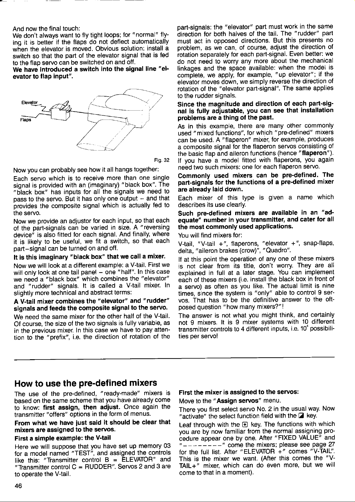
now the
And
We don't always
is
inq it
wf,en the elevator
switch
flap servo can
to the
have introduced
We
evator
you
Now
Each servo
signal
"6lack
pass
to the servo.
irrovides
final touch:
want to
better
so
to
if the flaps do
that the
flap input".
probably
can
which is to
provided
is
box"
with
has inputs
the composite
the servo.
provide
we
Now
part-signals
the
of
device"
is also
it is likely
part-signal
It is this
Now
will
we need
and
slightly
A V-tail
signals
We need
Of
imaginary
we will
look at one tail
only
a
"
rudder"
more
mixer combines
and
the same
course,
in the Drevious
to the
tion
an adjustor
fitted for each
to be
useful,
can be
look at a different
"black
signals.
technical
feeds
size of the
the
mixer.
"prefix",
fly tight
moved. Obvious
is
part
of the
be switched
a switch
see how
loops; for
not
elevator signal
on and
into the signal
it all hangs
receive
(imaginary)
an
for all
it has only
But
signal
the signals
which is actually
for each
varied in size.
be
can
signal.
we fit a switch,
turned on
"black
and off.
box" that
example:
panel
box"
-
one
which combines
lt is called
and abstract
"elevator"
the
the composite
for the other
mixer
two signals
In this case
i.e. the
direction
"normal"
deflect
automatically
solution:
off.
together:
more than
"black
we need
one output
input, so
A
And finally,
so that
we call
V'tail.
a
"half".
In this
the
V-tail mixer.
a
terms:
and
signal
to the servo.
half of
fully variable'
is
have to
we
of rotation
fly-
install
that
line
a
is Jed
"eh
Fig.32
one single
The
box".
to
-
and that
fed to
that each
"reversing
where
each
a mixer.
First we
case
"elevator"
In
"rudder"
Vtail.
the
as
pay
atten-
of the
part-signals:
direction
must act
oroblem,
for both
in opposed
as
rotation separately
need to
not
do
linkages
and the
comfllete,
elevalor
moves
rotation of the
to the
rudder signals.
Since
the magnitude
nal is fully adiustable,
problems
As in this example,
"
used
can
mixed
be used.
a composite
the basic
lf
vou
tlap and aileron
have a
neäd two such
Commonly
part-signals
already
are
Each
mixer of this
describes
Such
equatC"
the
You will
V{ail,
delta,
lf at this
is
pre-defined mixers are available
number
most commonly
find mixers
"V-tail
"aileron
point
not clear
explained
of these
each
a servo)
times,
as often
since
vos. That
posed question
The answer
not I
mixers.
transmitter
per
ties
servo!
"elevator"
the
halves
directions.
we can,
of course,
for each
worry any
space available:
we
apply,
for example,
down,
"elevator
we simply
part-signal".
and direction
you
are a thing
of the
there are
functions",
"flaperon"
A
signal
model
mixers:
used
tor the
for which
for the f laperon
fitted with
one
mixers
tunctions of
laid down.
type
its use clearly.
your
in
used
for:
+", flaperons,
brakes
the
Jrom
in lull at a
mixers
the system
has to be
(crow)",
operation
its title, don't
later stage.
(i.e.
you
as
ls
the definitive
"
how many
is not what
lt is I
controls
mixer systems
4 di{ferent
to
part
must work
of the
tail. The
But this
adjust
part-signal.
more about
reverse
the direction
Even better:
the
when
"up
elevator";
the direction
The same applies
each
of
can see
that
past.
many other
"
pre-defined" mixers
for example,
mixer,
servos
functions
(hence
flaperons,
for each flaperon
can be
is
transmitter,
pre-defined. The
pre-def
a
given
a
and cater
applications'
"elevator
"Quadro".
of any
+", snapJlaps,
one of these
worry.
You can
install the black
The actual
like.
"only"
to control
able
answer
mixers?"
you
might
!
think, and
with
inputs,
i.e. 10-
in the same
"rudder"
part
presents
we
mechanical
the model
if the
part-sig-
installation
commonly
produces
consisting
"tlaperon").
you
again
servo.
mixer
ined
in an
which
"ad-
name
for all
mixers
They are all
implement
in front of
box
limit is
nine
9 ser-
to the
oft-
certainly
10 different
possibili-
no
of
is
of
oJ
How to use
use oJ
The
based
know:
to
transmitter
what
From
mixers
First a simple
Here we
model
for a
this:
like
"Transmitter
to ooerate
46
the
the same
on
first assign,
"oJfers"
we have
are assigned
example:
will suppose
named
"Transmitter
control
the Vlail.
pre-defined mixers
the
that
then
in the
said
"
ready-made"
you
have already
adiust.
Once again
form oJ menus.
it
should
pre-defined,
scheme
options
iust
to the servos.
the V-tail
you
that
"TEST",
control
=
RUDDER".
C
have set
assigned
and
=
B
ELEVATOR"
Servos
mixers
come
clear
be
memory 03
up
the controls
2 and
is
the
that
and
3 are
First the
Move to
There
"activate"
Leaf through
vou
öedure
for the
This is the
TAIL+
come
mixer is assigned
"Assign
the
you
first select
the select
with the
are bv
now
afpear
full list.
mixer
"
mixer, which
to that
in a moment).
servos"
servo
function
E
familiar
one by
After
from the
one.
"ELEVATOR
we want.
can do
the servos:
to
menu.
in the usual
No.2
field with the
The
key.
normal assigning
"FIXED
After
(After
even
way.
key.
Z
lunctions with
VALUE" and
+" comes
this comes
more, but
"V-TAIU'.
the
we will
Now
which
pro-
"V-
Page 49

You will
Press the
whole
now
complete.
You have now " informed"
Servo
V-TAIL.
It
also
betore each of the two servos. In more
you
have
mixed function".
Leave the menu in the
Now we come to setting
Move to the " Servo adiustment" menu. Press the
key to
Select servo
You will see this:
Press
(stick
back) and then the other side
as if setting up
this case why
set both
you
lf
practice procedure,
this
the stick makes the elevator rise. lf this is not the case,
press
the
Note:
you
lf
set mixing
the mixer will operate in a " lineat" fashion, and
then
the control signals
on the
such a case,
you
time,
soon as the sum of the two
face exceeds 1000/0, i.e. when a lot of elevator and
der are applied simultaneously, the movement will be
restricted, as the servo and the control surface cannot
move to more than 1000/o of maximum. The etfect
aerodynamic
"
Linear" mixing
elegant
between
comoromise.
Now to the rudder
put:
ELEVATOR" is now replaced
You will see this:
Press the
both directions of
Here
side.
this:
see
H55Irjt.l SEFlr,IÜ
tJ-TFll
Tü
key, select servo No. 3 and repeat the
[!
for
thing
No. 2
knows
assigned servos 2 and 3 to the
select
the
to, say, 400/o.
have an actual model to hand while
El
other hand, leave both inputs at, say, 1000/0. In
solution, but in
the two extremes has
this servo.
operates
it is
that
the sub- menu
No. 2 in
rSEF:.
r+ I
key
\l
key, and it will be reversed.
if
will
asymmetry which can be disturbing.
r5EFj.
\+ I
key again, then set the " ruddet" input for
Sl
again, check that
the usual
r:
rittjt:.:
and adjust the lhrow to the one side
in
the
you
should set unequal movements, so
ratios
will never
you
apply elevator or
have full
(no
input.
rr
t:Jtit:.j
rotation; in
The
assignment
your
transmitter that:
V-TAIL,
usual
and Servo No. 3 operates
place
to
up
r.r-19
the appropriate mixer
way.
the mixer.
"TRAVEL
wav
i '_
Elt' ELEtltlr
(stick
normal way.
check at this
which add up to less than 1000/0,
travel available.
inouts
more than 1000/o) is the most
practice
Press the Z key, then
r.r.
There is no reason in
restricted. You
be
for either control sur-
a setting
proved
by
THIL
[:+ FIU[r[rEr
our example 600/0 for each
the
control surfaces
I
I
L r
process
abstract terms:
"V-Tail
REVERSE".
+
forward),
you
carry
point
rudder
a very effective
"Part:
"up"
that
one at a
However,
part-way
El.
RUDDER".
higher
just
could,
rud-
"ln-
move
is
Z
out
on
as
is
in the correct direction
Reverse the function, if necessary with the E key.
We hope
mind
servo No. 3!
Note:
Bear in mind that the travel inputs for the mixers
switched ON/OFF or assigned to a
you
page
And now a more complex
At
the start of this Section
featured
flaps
We will assume that transmitter
assigned
"spoiler"
The following
Servo No. 2: elevator
Servo
Servo No. 6: camber-changing flaps
Here we
although
an indirect
We will assume that the
closed) of
the stick is
At the
present
proportion
need to be
The
"
Normpos"
have not
otherwise
tion. Please reler to
You must
arrow
spoilers are
This action comoensates for the undesired basic mixino
inout
on the signal to the spoiler servo itself.
From now
other of
tively,
adjusting the elevator, as described above.
But enough of the
First
Move to the
sequence
For servo No. 4
mixing. So,
select servo
Now to the elevator.
Select servo
tunction field starts flashing. Leaf through with the
key.
After
"
ELEVA'IOR+
you
-
are
30.
and spoilers, and elevator to
basic
-
transmitter offers a better alternative,
in
before
its
you
step,
Once again the
"FIXED
didn't Jind that all too confusing. Never
you
not
pitch
to
tunction and control F to the
No. 4:
come to another special
it has nothing
sense.
control
pulled
namely full travel forwards.
would reach the elevator, and then would
"compensated
yet
you
set this option to
the display).
on take care that control C
end-points
could switch the
as always: assigning:
El El [l N
repeat
can
sure how to do this
trim compensation for camber-changing
"elevator"
the
servo assignments have also been made:
spoilers
D is
right back.
position
(Normal
tackled this feature,
will encounter
retracted with the
it räaches the mixer. lt has no eflect
preliminaries.
"Assign
(spoilers)
as with
iust
No. 4,
then assign
No. 2,
VALUE"
":
(if you
the
to do with mixing, is important in
"forward";to
very large
a
away" by some means.
Position)
page
37.
Assuming,
for
all
servos"
.
everything is clear; there is no
press
then
lamiliar
and
have a model handy).
whole
example
we
discussed a model which
function,
"basic
problems
your
"SPOILER"
"normal"
"SPOILER"
"list
operation
physical
please
flap mixing.
control
control D to the
"flap"
feature
position" (spoilers
extend the spoilers
signal
Of
control option.
you
should do it now;
in the next
"forurards"
that
forward!
stick
is
adjustments.
menu with
assignment, first
the Z key; the
of options" appears.
switch.
refer back to
B has
function.
is
this a certain
namely
(forward
is,
that
to
set
input
off
the
it.
to
now for
can be
lf
been
which,
already
the
you
lf
sec-
your
aä
at
or
one
Alterna-
when
key
control
E
47
Page 50
1155Iril..l
is the mixer
This
preamble
in the
follows.)
That's äll
Select
with the
For an unmixed
"FLAP";
tinue
name of
there
servo
Z
because
leafing through
the mixer
effect:
II:,5IIJH
Now to
Move
Servo
say about
point (if
The
really call
assigned
Well, that's
Select
In the second
we will set up
Release
flashes). Check
correct.
selves?
as this depends
length of
surfaces.
themselves;
ooint
degrees
then
vatues.
Now to the
Press the
ing, the display
the setting-up
to the
No. 4 is the
it: set
necessary)
flap
servo
the SNAPFLAP
servo No. 6.
r:-1EF:.
t
the
lf not,
We cannot
the actuating
lt is best
would
down. Set
the other,
"elevator"
!
that we need.
to the detail
is to it; flap servo
No. 6, then select
key. Leaf through
of the
"Servo
first
the direction of
(No.
it the snapJlap
your
how
+Itli:
line
input first.
this
input value
whether the
press
on
for
camber-changing
be around 5
and use the
key, then the
will
r5EFl.
r+ 1riifi:t
value tield with the
Activate the
Check
elevator
evator
with the
the desired
set
Repeat the
point
ing
flap detlection;
later on, during
tings
input
direction of
the
must move
with downJlap.
key. Apply
E
flap deflection
process
for both sides
you
5EFitlu
ELEtl.
Tr_r
(lt
description
i
+
is described
of mixers
next:
the servo
again with the
you
flap function
mixer, however,
'SNAPFLAP"
until
which
produces
5EH[.JÜ
TI:I
adjustment"
in the usual
6) comes
You see this:
SHHFFLI-IF^T
process.
to adjust.
one
way.
next. In this case
servo,
function to
transmitter
l.J-Ttl
i:
would now select
you
the
E
menu.
There is not
rotation and the
because
it. Hair-splitting?
it.
sees
l L
F't' FLHF
you
will see
the E key.
you
tell
your
model, and
arms on lhe servo
to measure
the slider to
inout.
look like this:
"FLAP"
field with the
direction of servo
But the values
exactly
-
10 degrees
E
El
what they should
particular
in
the result on
flaps a
the one end-point
and
key. With
keys to set the
El
ELEVATOR
E,: :;HHFFLIIF
Ert ELEt.Jl.lr
!
rotation; for snapjlaps
servo
in opposition
ls that
"full
up" at the
"full
for
would be around
will be able
test-flying.
to the flaps,
how it is?
elevator stick,
with the
down" elevator.
to find the optimum
I
r
in detail
which
function tield
key.
El
have to
appears:
desired
1
on the right. So
S
and the
good
up and
key once
lf not, reverse
or
El
A
-
5
con'
the
mixing
much to
centre
we
should
we have
(value
key
rotation
the flaps
i.e. up-el-
E
good
10 degrees
is
them-
be,
on the
control
starting
15 - 20
and
0/o
flash-
more.
the
and
keys.
start-
set-
you
Do
tor
remember that
---
f lap mixing switchablet
That comes
You can - or
switch
because
on
Now
sequence
Press the
appears
must be
coupling
press
You
elevator
case
First
is to carry oul
your
you
what
move to the SWITCH
EIZ Z
0l
and
pushed
is then effective.
the E key, and
finished
are
(more
No. 2.
move to the
Select servo
will look
like
rtEF:.
L+ 1
"ELEVATOR"
Input:
first. Release
check
Then set the travel
usetul starting
The
but we don't
in detail again.
select the
tunction
switchable
SNAPFLAP
Our
confident
site,
you
not always
tlying strip
"mild
error
doing,
The
supplied
thihg
the
input values.
Never attempt
when
Adiustor,
the E and
The basic
whlle
One
it
last example
Try
flap function
of the adjustments
control still
with a switch.
the direction of
"SPOILER"
input, set the
if necessary
Practise
tip:
with the
you
will also need to
make sense of the
can
stress situations"
-
unless
that is.
same
with the
yourself.
mixers unless
you
which is always switched
you
final thing
the transmitter
out
we wanted
next.
-
rather, must
PROFI
can and
mc 3010 sets
cannot do)
this task
tell the
(you
virtually
menu,
by
from the basic display.
key.
Iap the
El
repeatedly until
key
flashes. The arrow shows
lf
is
you
done.
to switch
want to reverse
in that direction
job
the
with the snapJlap
accurately:
ELEVATOR+)
TRAVEL & REVERSE
2 with the Z and
No.
El
this:
::
|i1fi:t
the input
point.
and
need to describe
In both cases
has already been
function.
mixed
Et ELEtJHT
is already there,
value field with
rotation;
itself on both
"FLAP"
value tor both sides.
The method
"adiusting
procedure.
ELETJ.
so
reverse it
sides: 900/o
inputs are
the adjustment
it is all
know
"business
of making the
described
inputs" until
Later on,
what to do, so that
test-flying
quite
as it
applies
are
keys,
El
rule
are
(this
(see
functions
quiet
as
is in
and calm out
your
workshop; and
you
you
if
transmitter,
lt is almost
to adiust
flying a
contident of
are
you
use
the
without assigning
impossible
you
know how to set
anything
model. Instead
when it makes sense
is
this:
keep the
flying!
you
has nothing to do
page
like to try out
might
control option
You will see that
36).
you
have made
"ovenide"
you
if
can easily
"ready-made
with mixers):
"
to make
transmitter
the eleva'
have to
which
do this
no restrictions
pressing
the key
"55+"
the switch
that
it ON, i.e. the
this,
servo.
Now to the
servo,
in our
menu.
The
keys.
display
+
we will set that up
the ! key, then
if necessary
would be a
adjusted
Reverse
at the
process.
there on
what
to use any of
and adiust
trom the
use the
"in
parallel"
to use
keypad
in addition to
Value" for the
Fixed
every aspect
regarding the slider
the slider
next,
procedure
as usual":
the
inputs
for the
you
are
flying
lt is
the
in
such
make an
you
are
lists"
any-
keypad
oigi-
with
it.
flap
shut
the
position
4a
Page 51

Description of the
"ready-made"
you
Now that
mixers are assigned and adjusted,
pre-defined
offered by the transmitter
have
become
mixers in the same sequence as they are
pre-defined,
mixers
familiar with the way the
here is a list
you
when
"leat
through" the
oDIrons.
With all
cally
standard oractice.
mixers
the stick unit trim sliders are automati-
included where it makes most sense, or where
You
don't
need
to concern vourself
with them at all.
Examoles:
"V-tail"
For a
"snap-flaps"
for
For each
of the servo)
mixing input
can be adjusted. The inputs can be switched
the elevator trim
it does not.
the size and the
works in
pretix (rotary
the usual
on and off wherever that is of oractical advantaoe.
the
of
it is
way;
sense
You can assign each mixer as often as
demands
Examole:
You must use the
less than that
"Quadro"
should not use it six times if
control surfaces
One more time
You can set any
altogether. This may make a
for a different, but similar
Examole:
With the
input to
"flaps"
it.
"Quadro"
number means
mixer at least
it is no longer a
that
mixer. However, there is no reason why
your
model has
on
each side.
-
just
to remind
input
lo
"
zerc"
you:
and
particular
purpose.
"Quadro"
zero,
and
"ailerons"
and
you
mixer
then
only.
you
could set the
have a mixer which involves
your
then
disregard
mixer
application
four
times;
you
wing
three
it
suitable
"elevator"
Mixers
The
lnouts:
for fixed-wing
"ELEVATOR+"
Elevator
Sooiler
FlaD
The mixer
is
mixer
usually assigned as
models
etevalor
sporler
flap
follows:
Elevator servo
Main application:
Standard
models
with
camber-changing
or landing
flaos and/or sDoilers.
The
"V-TAlf
mixer
lnDuts: Elevator
Rudder
mixer is
The
V-tail servos
usually
Main application:
Model aircraft
"V-TAIL+
The
Inputs:
Elevator
Rudder
Spoiler
assigned as follows:
with V-tails
"
mixer
elevator
ruooer
sporler
flap
Flap
The mixer is usually assigned as
follows:
V-tail servos
Main application:
Models with V-tail and/or spoilers and/or
camber-chang-
ing or landing flaps.
"aileron
The
lnouts:
brake"
Aileron
Flap
Sooiler
Elevator
The mixer is usually assigned as
Flap
and aileron servos. Usually
Main application:
Models in which the
as an aid to flight
(descent,
"aileron
The
Inputs: Flap
landing approach). Can also be used
brakes".
"SNAPFLAP"
Elevator
(Crow)
"Crow"
path
control
mixer
mixer
atleron
sporler
elevalor
follows:
4 servos.
configuration
in
certain
llight
,an
etevalor
The mixer is usually assigned as lollows:
Flao
servos
Main application:
F3A class aerobatic
"QUADRO"
The
lnouts:
Aileron
Flap
Elevator
mixer
models for
"souare"
aileron
elevator
The mixer is usually assigned as follows:
Flao and aileron servos
Main application:
Gliders
ailerons,
"Quadro"
with
flap conliguration
ailerons support flaps)
(flaps
is to
be used
situations
pure
for
manoeuvres
support
"FLAPERON"
The
Inputs:
The mixer
Aileron
Flap
is
usually assigned as
Flaperon servos
Main application:
Models
with f laperons
mixer
lollows:
(combination
aleron
flap
flap
i ailerons)
The " DELTA' mixer
lnDuts: Aileron
Elevator
The mixer is usually assigned as follows:
servos
(combination
ailerons/elevators)
Main application:
delta model aircraft and
flying wings.
49
Page 52

model
Mixers
The
Inputs:
for
"TAIL
ROTOR"
Collective
Yaw
value
Fixed
The mixer
is usually assigned
Tail rotor servo
Main application:
Model
via tail
The
Inputs:
helcopters
rotor
"HEIM
HEAD" mixer
Collective
Roll
The mixer
Swashplate
is usually assigned
actuation
Main application:
Model
helicopters
or similar
helicopters
mixer
pitch
with main
pitch
servos
with Heim-type
collective
fixed value
follows:
as
rotor torque
collective
follows:
as
pitch
yaw-axis
compensation
pitch
roll-axis
swashplate
linkage,
The', DYNAMIC-THROTTLE',
lnputs:
The mixer
"Throttle"
Throttle
Roll
Pitch-axis
Yaw
is usually assigned
servo
MiXCT
as
Main application:
which throttle
model helicopters
All
directly
by the
ing to the
SDecial
The
"without
feature:
"roll", "pitch-axis/r,
main and
"FLARE"
The
pilot,
power
prefixes",
tail rotors
mixer
Inputs: Pitch-axis
Collective oitch
in
is controlled
but
absorption
of the
and
power
the
as
rises from
collective
"yaw"
zerc
pitch-axis
throttle
roll-axis
pitch-axis
yaw-axis
tollows:
is not controlled
indirectly
main and
tail rotors.
inputs are
requirement
"on
both
pitch
throttle
servo
accord'
mixed
of
sides".
pitch-axas
servo
the
"HEAD-MIX"
The
Inputs: Collective
mixer
pitch
Roll
Pitch-axis
Geometry
Phase
The mixer
Swasholate
Main
Model
plate
The freely
In
contrast
Drevious
the
require.
for which
Once
used
This
exactly
switches
and
These
is usually
control
application:
helicopters
linkage
definable
to the
Section,
chance
they
exactly
means
off.
to select
This feature
pre-defined
no
have been
like the
that they
the same
provided
are
mixers
give you
servos
with
"pre-defined"
the
way. And
Note:
practice,
In
the
term
select:
Input 1 controls
(say)
tor
you
is all
That
now assign
can
you
when
need to do
the mixer
try out
the system,
No trims!
Right
input
the
Inout
E.G.
then, back
field with the
to defining
1
geometry
collective
pitch-axis
assigned
"Collective
as follows:
Pitch
mixers
mixers discussed
user-definable
precisely
caters
mixers are
"defined",
"pre-defined"
are assigned
for turning
total
"defining
aileron
key, and add
E
the mixing
for all
possible
provided.
these
mixers.
in exactly
individual
freedom!
mixers"
Input 2 controls
to define a
in the standard
you
will discover:
the USR-MIX
pitch
rolFaxis
phase
Mixing"
swash-
("USR-MlX"
in the
mixers
and
means
delta
the
give
inputs
applications
mixers can
adjusted
the same
way,
inputs
that
(say
eleva-
mixer.
way. However,
mixer, release
trim.
you
you
be
in
on
you
You
mixer is usually
The
Pitch-axis servo
Main application:
Helicopters
lueter,
with separate
"Shuttle"),it
mixers)
1. AIL +T
And the
wrong?
No, there's
modified
menu, select
input
altered
You may
this
you
lf
potential:
the
Since
can
assignment
vos has
to be
The USR
have the
Al this
before,
result?
nothing
USR-mixer.
the
field. The
USR
legend USR-MIX
mixer
lind this difficult
"trap"
alter the
in Jact offers
really clever,
are
have to
we
USR
(servo
its own USR
a drawback.
mixers
name, e.g. USR-MIX
same
point
in
answering
"My
will come back
we
transmitter
can indeed
assigned
"
tlarc"
Nothing!
wrong:
Move
appropriate
as follows:
pitch-axis
mixing
servo
is
desired.
Has the transmitter
you
lirst
must re-assign
to the servo
servo,
and activate
1 flashes
is
active.
bear
or complex,
immense
you
will already
re-activate the
but
possibilities.
have
mixer each
mixer definition between
1, 2, 3 etc.),
mrxer. But
so that each
-
of course
all be diflerent,
1.
game
question:
yours?"
your
has 6
to the
friends'
mixers; and
(e.9.
Sch-
gone
the
assignment
the
-
now the
with us;
realised
we
time,
servo
each
9 ser'
of the
-
but
we
there
they all
played
has
50
Page 53

Independent
which
of
mixers.
for all
oer
Sample
As
model aircraft.
habit of
the
motor). Quite
time
an easy
ing board.
Now,
in with
was aDDlied
need a
four channels.
servol
the
"throttle"
thinking
wouldn't
of the
you
can apply
These can
applications:
first example,
lmagine also
becoming
is opened
why this
about:
life, or
it
"throttle"
the
as the
"motor"
13 ready-made
I times,
be assigned
That means:
imagine
more and
(the
occurs
perhaps
maybe
be
and
he made a
if we could
nice
automatically,
throttle
"elevator"
was opened.
mixer systems,
you
now have
1.0 different
up to
that it
more tail'heavy,
more
we don't
the modeller
mixer.
possible
10"
an electric-powered
has the unpleasant
power
mistake at
mix down'elevator
that more
so
the USR
the
is ted to the
need to waste
just
the build-
We would
each
inputs
mixers
more
wanted
"down"
then
possible
Ot the
"MOTOR',
and
there
Now we will
see
is.
Press
function can be
until
Now to
El.
then
appears:
four
other
"name"
"lNP1",
"lNP1"
the
oJ the
is nothing to
"define"
which
the
"MOTOR"
the second
leaf through
key; and
Z
turns
rl_l5F:-t,lI
r I f iF
inputs
for
mixer)
be done
the
is the first
entered.
appears.
input.
"lNP.2".
into
with the
we need only
"ELEVATOR".
you
will see
here.
inputs
the
That's
in turn:
we
input;
"type
Leaf through
Press the
El
l':1
of input"
it done.
!
Press the
key until
+T+F:]
i
. i: ELEr,.rH
2: one
In line 1
"USR-MlX1";
in line 1
leave
can
=
with the
followed by
key,
key again,
Z
"
ELEVATOR"
jor
(Number
i.e.
you
will
it as
control
key
E
I
it
elevator
A
Second
screws
When
fed
other
Here
inouts
lf the
control
'MOTOR"
even
How
Every definable
mixei,
tions
That
Naturally,
will
signing"
Starting
ing"
"USR-MlX"
for a mixer
case
example:
motors
the
"right
with more
way round
we
"
two
more sophisticated,
to
we need
it is to send
is what
find
menu with
rudder" is applied,
current,
when
need tvvo
rudder"
from
"define"
in the
from the
and
rudder
rudder
molors
the transmitter,
"
and
to tell the
we mean
is done by
this
"bottom
menu.
with the
rutFt-f'lI
rIl'.|F.1:
will
we
Now
This will be
detine
USR
+
trim
molor
-
a USR-MIX
in a model boat
are required
and the
"left
mixers ol the
"
motor":
motor
+
trim
motor
+
trim
have already
MOTOR-2",
the mixer
mixer
to these
the key sequence @ Z N
has tour
by
right-hand
Status display,
key.
Z
etevalor
servo
mixer.
with
to support
left motor
the
right one
rudder"
we won't
but
transmitter
inputs.
"defining".
means
You will see
iil
is
applied.
same
controller
motor
R.H. motor
motor controller
motor
L.H.
been set
using
then
the assignments
the solution
inputs.
which control
of a
corner"
more to
+T+E:i
i
2 motors and
go
into that
To define
menu, which
this display:
rj".
the
mixer 1.
mixer
for the
first example.
rudder.
the
is to be
less; and
type for
for separate
of
the
then select
;
the
the
be
can
here.
the
func-
you
"As'
the
"Assign-
r
Now
It is always
undesirable
we ought
2
Select
input No.
really does
This
the usual
At this
you
are taken
menu,
not wish
The result
To assign
until vou see
'
you
lf
thö other
EVATOR".
The
second
For this
input
you
ft
relinement
work
later switch oft
Input4
This mixer
you
really
possible
left
to have a
input 3
(Nothing)
4; otherwise
appears.
with the
way
point
a
where
you
to do this,
your
of
finished.
are
here from an
look, to be
as discussed
Repeat
complete
"operating
little
immediately
can
just
work, in diagrammatic
n#liif_,if
ffiiilr8lil
mixer to
this
"Servo
want to adiust
mixers,
example
you
use
1; " RUDDER"
assign
out
is again set
'MOf
is automatically
what it is?
in diagrammatic
No. . controls
adjust both
USR mixer
to
-2'
inputs to
or set
to
motor
ruooet
motor 2
nothing
Inputs 3 and
that there
there,
leaf through
the task.
key.
@
carry out
press
could be
earlier
on the safe
above.
move on
with the
process
the
convenience"
the
to
this
again.
@
"",".
the elevator
USR-Mlxl'.
I
this servo,
in abbreviated
input 2.
the 3rd
to
(clue:
number
you
inputs
available.
bear
form:
"MOTOR"
Assign
2.
input, then
in
zero).
(Nothing).
molor
(motor
4 are not
something
mixer definition,
side:
you
ll
immediately
E
with input
Leave the
"Assign
process.
servo,
must then,
form:
Why
mind that
controller)
is built
lf
form:
leal through
ot seNo
and
"MO'rOR"
not try and
so
see
to
key until
4.
menu
a further
in
in:
sewos"
you
do
with
as
"EL-
to
you
can
cl
Page 54

now
And
What
With many mixers
slider
ple,
oossible
also
model.
On the
tion of the trim sliders should
"snapjlaps"
wing control surfaces
elevator
required when
It depends
whether
trims, and
You
We will return to
We had
one small,
happens to the trims?
positions
that applies
to trim the elevators
applies to
other hand there are
trim slider
you
choose this too:
can
this display:
with the
to a V-tail, otherwise
the elevator control of a
on an aerobatic
"control"
you
theretore on
want the
this applies equally to the USR
the first
very important difference:
but
it is necessary to include the
"pure
not be included.
should not deflect
is
shifted;
the elevator.
your particular
mixing inputs with or without
example
stick signal".
and rudder.
mixers in which the
model. In this case
flap movement is only
we discussed
For
exam-
it would not be
The
same
llying wing
posi-
Example:
when the
application,
mixers.
here.
trim
the
ru:,Ft-fl
r I l'lF.
Press the
you
lf
now
This means
tion is now
you press
lf
and the
One last time:
Please bear
you
that
you
alter their definition,
not take eftect.
key
Z
again;
press
the
"with
mixed in with the ELEVATOR
rU:;Fj-l'1
r I I'lF. :: ELEr-rH+Tr
the
El
mixing occurs
in mind
re-assign the USR-Mixers every time
must
I iiI
{:+T+F:i
r: ELEr"rH
"ELEVATOR"
key, " +T" will appear
E
trim", and
indicates that the
I :'i I
key again,
"without
(as
"+T"
already
otherwise the changes
flashes.
{: +T+F:
disappears again,
trims".
described above)
r
input:
i
next
trim
it.
to
posF
will
Over the course
has developed
machine.
radio control
PROFI mc 3010, with its
match
to the specialised
fined
ceivable
the
page
you
lf
lollowing Section
you
ll
we strongly advise
magazines
information
That is not because
but because
because
with a
as
this
copter
easy
tixed-wing
are explained
The
for all these requirements;
mixers, which can be used to
need. Experts
possibility
68).
already
are a beginner
is not
it
fixed-wing model. lt is far outside
manual to
control systems, as
to understand
models. Some of the commonly
of its existence the
into
a sophisticated
demands
system are no
"helicopter
will
"switching
of
have
some
probably present
will
to the world oJ the
you
and specialist books
in this
manual.
the PROFI
helicopters are
possible
go
into
the basics
nor as easy to
in
this section
model helicopter
and demanding
these machines
less
comprehensive.
vast flexibility, is more than a
thanks in in
mixers" and the user-de-
fulfil
also be
memories
experience with choppers
to read and study
to complement the
mc
3010
inherently complex.
to start with 2 or 3
and finer
they are by
imagine as those of
where necessary; and
make
almost
delighted to exploit
in flight"
problem.
no
whirling rotor,
modelling
is complicated,
functions,
the scope of
points
no means as
used terms
the
on
The
particular
any con-
(see
the
And
heli-
of
you
find
will
copter
In
are
so that
helicopter.
Even if
specialist
with
iar with the way the transmitter
As a minimum,
method of finding
selecting,
mitter controls.
Basically the
same
have said up to now on
and so on, applies
However, there
modern model
mixer right
eral mixers.
another
world.
But now: down to business.
some
terms" on
this Section
already familiar with the
we
you
fixed wing examples, so that
the
way
further explanations under
page
76.
we start from the assumption
way the transmitter works,
can concentrate
consider
you
should
correlating and adjusting
"helicopter"
for a fixed-wing model.
as
from
The
feature which is
yourself
you
your
in f
is
one
helicopter is tlown with at
the start, and
"collective
on the characteristics oJ the
an expert and a
at least carry out a
works.
should
way
working with memories, mixers
to the helicopter transmitter.
ull
fundamental difference: every
teel
around
transmitter is operated
most oJ them
Ditch/throttle
peculiar
"Some
that
helicopter
"dry
few
you
become
home with the
at
the menus, and
servos and trans-
Everything that we
to the
runs"
famiF
in the
least
feature
curve"
helicopter
heli-
you
with
one
sev-
is
52
Page 55
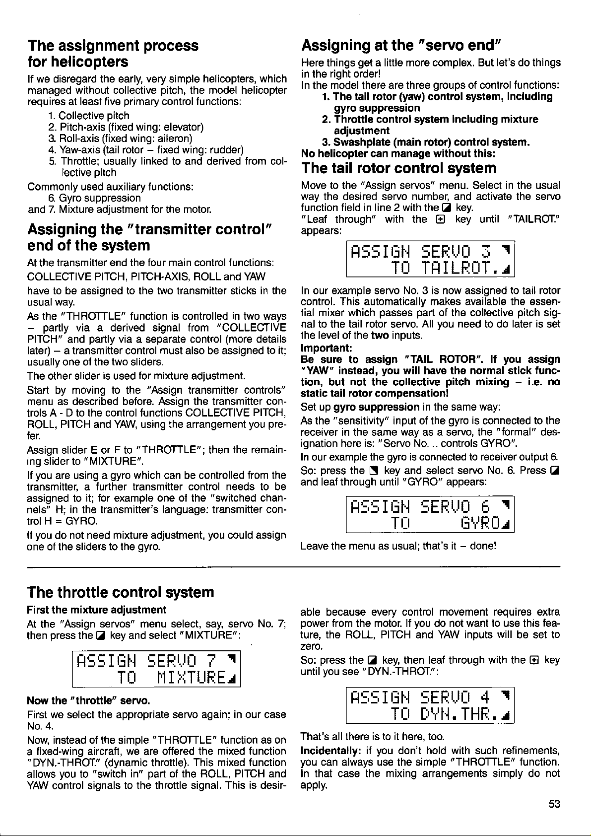
The assignment
helicopters
for
lf we disregard the early,
managed without collective
requires at least five
1.
Collective oitch
2. Pitch-axis
3. RolFaxis
4. Yaw-axis
Throttle;
5.
lective
Commonly used auxiliary functions:
6. Gyro suppression
7. Mixture adjustment for the motor.
and
(fixed
(fixed
(tail
usually
oitch
Assigning the
end
At
COLLECIIVE
have to be assigned to the two transmitter sticks
usuar
As the
PITCH" and
later) - a transmitter control
usually one ol the
The other slider
Start by
menu as described before. Assign the transmitter con-
trols
ROLL, PITCH and YAW using the arrangement
fer.
Assign slider E or F to
ing slider
lf
transmitter, a
assigned to
nels"
trol H = GYRO.
lf
one of the sliders to the
of the system
transmitter end the four main control f unctions:
the
PITCH, PITCH-AXIS, ROLL and YAW
way.
"THROTTLE"
-
partly
you
you
via a derived signal from
partly
two
is
used
moving to the
A - D to the control Junctions COLLECf IVE
to " MIXTURE".
are using a
H; in
do not need
gyro
further transmitter control needs to be
it; for
transmitter's language: transmitter con-
the
mixture
process
very
simple
pitch,
primary
wing: aileron)
rotor - fixed wing: rudder)
control
wing:
linked
elevator)
to and derived
"transmitter
function
via a separate control
sliders.
for mixture
"THROTTLE";
which
example
gyro.
is
must
"Assign
can be controlled
one of the
adjustment,
helicopters, which
the model helicopter
functions:
control
controlled
also be assigned to
"COLLECrIVE
(more
adjustment.
transmitter controls"
then
"switched
you
from
col-
"
in the
in
the remain-
could
ways
two
details
PITCH,
pre-
you
trom the
chan-
assign
it;
Assigning at the
Here
things
in the
In
the
1. The tail rotor
2.
3. Swashplate
No helicopter can manage without this:
get
a little more complex. But let's do things
right
order!
model there are three
gyro
suppression
Throttle
adiustment
control system
"servo
(yaw)
(main
end"
groups
control system,
rotor) control
of control functions:
including mixture
system.
including
The tail rotor control system
Move to the
way the desired servo number, and activate the servo
f unction field in line 2 with the Z key.
"
Leaf through" with the
appears:
In our example servo No. 3 is now assigned to tail rotor
control. This automatically makes available the essential mixer which
nal to the tail
the level of the two inputs.
lmportant:
Be
sure to assign
"YAW"
tion, but
tail rotor compensation!
static
Set up
As the
receiver in the same way as a servo, the
ignation
In
our example
press
So:
and leaf through until
"Assign
H5:,Iriil 5EF;r.Jü I
rotor
instead,
not
gyro
suppression
"sensitivity"
here is:
the S key and select servo No. 6. Press
r-r:,:,I
servos" menu. Select in the usual
key
E
TI:I TI]
passes part
servo.
"TAIL
you
will have the normal stick
the collective
input of the
"
Servo
gyro
the
is connected to receiver output 6.
"GYRO"
riH
I LEL-'IT. ^T
of the collective
you
All
ROTOR". lf
in the same way:
No. ..
controls GYRO".
5EF:Url ü
pitch
gyro
appears:
until
need
to do
mixing - i.e. no
is
connected to the
"formal"
"TAILROT."
I
later is
you
I
pitch
assign
func-
sig-
set
des-
Z
Tr:r tiirFtür
Leave the menu as usual; that's it - done!
The throttle control system
First the
At the
then
Now the
First
No. 4.
Now
fixed-wing aircraft, we are otfered the
a
"DYN.-THROT."
allows
YAW control signals
mixture adiustment
"Assign
press
servos" menu select, say, servo
the Z key and select
t1:,5IüH sEFlr,lr_t
TÜ
"throttle"
we
select
instead of the simple
you
to
servo.
the
appropriate
(dynamic
"switch
to the throttle signal. This is desir-
I'II !{TUFIE/
servo again; in our case
"THROTTLE"
throttle).
part
in"
of the ROLL, PITCH and
"MIXTURE":
T
This mixed tunction
No. 7;
I
function as on
mixed function
able because every control
power
ture. the ROLL. PITCH and YAW inouts
zeto.
So:
until vou see " DYN.-THROT.":
from the motor. lf
press
the
key, then leai through with the
tr
t:t5!;itjH :,EF:t.t[t 4
movement requires extra
you
do not want to use this
will
r
be set to
E
T[t ['tr't'], THF:. r
is
That's all there
lncidentally: if
you
can always use the simple
In that case the mixing arrangements simply do
appty.
it here,
to
you
too.
don't hold with such
"THROTTLE'
refinements,
lunction.
fea-
key
not
Page 56

The swashplate control
we
Here
nology,
systems,
other.
trol of collective
the
the
For this
of the
assignments
1. The
move along
rotor shatt;
Collective
via
inside the
shaft,
rotor shaft. Collective
cyclic
mechanically,
at the
plate
servos,
to each other.
There are therefore
axis and
tions.
you
lf
tive
transition
"
FLARE" to the Ditch-axis
Please
previous pitch-axis
2. The
CPM
linkage
swashDlate.
along
ally
cyclic
Three servos
three act on
as a 3-point
servos
A 4-point
You could even
the
ever
There are
three servos:
"120-degree
The
All three servos
the ooLLECTIVE
swashDlate
can't
as there are several
or designs,
In fact they all do the same
different systems
number of servos
reason we
three most important systems,
"classical"
a oushrod
or in a
is controlled by two
Servo
Servo
Servo
wish,
pitch
"CPM"
stands
the rotor shaft
produces
pitch
to control
rotor head, should a
come onto the
90-degree
required
the axis of the
it can only tilt.
pitch
hollow rotor
groove
pitch
rotor.
set at 90 degrees
pitch-
No. 1 controls
No. 2 controls
No. 5 controls COLLECTIVE
you
at a later stage,
from cruise
note that if
tor
is to some extent the
In this case
control.
the swashplate.
linkage.
linkage
two different
arrangement"
rises and
getting
avoid
which differ
pitch,
roll-axis and
make
and how they are used.
present
for
fixed swashplate
control
which runs
in the
and
mixed
are
"
higher
The
axis,
can mix in the
swashplate
collective
are again
the
arrangement
up",
swash-
Fio.33
three servos
which have entirely separale
to hoveo. To achieve
you
servo adjustments
"Collective
in the axial direction.
However, it is
the swashplate.
presents
"distribute"
market.
"go-degree
must tirst be assigned
PITCH signal;
falls
little deeper
a
different rotor
job:
quite
different
here
each:
is
",1
"*:*.
(+
clllocllr. lro|]l J S€rw 5
tor n ro
for
ROLL-axis
PITCH-axis
pitch-axis
you
if
find it necessary
servo.
change the
Pitch Mixing".
opposite of the
the swashplate
pitch
control; tilting
required, but in this case
This arrangement
possible
problem
no
more servos around
5 or
helicopter
methods of arranging
arrangement"
:
is the simpler
the result
evenlv
system
into the tech-
head control
widely from each
provide
they
pitch-axis.
demands on
a brief
description
U
l.
r.0ü!) Call€ciiv!
collective
PITCH
input to collec-
this, assign
assignment, all
will be lost.
This type of
is Jree to move
Moving it axi-
it
to use more
to the transmitter.
with these features
an equal
when the collective
con-
However,
the
and
,
ffi-'x
picn
pitch,
roll-
func-
(tor
the
the
fixed
produces
all
is known
these
and the
one.
part
of
is that the
I
AEargem.nt
pitch
control
outer servos are operated,
directions.
pitch-axis
The 120-degree arrangement distributes
the servos
For collective
receive an equal
nal. For roll control, once again,
vos are operated,
control.
outer
to the central one.
Even this is not the end of
ments must be different.
required to
the same amount.
far.
The same
the servos
This mixer offers
TIVE
each servo.
ROLL for the central
i.e. switched
The servo assignment
direction of the three
As
an
look like this
Finally the central
control.
more evenly.
however. all three servos
ones work together, but
produce a pitch-axis
"HEAD-MIX"
in both versions ot
collective
PITCH, PITCH-AXIS and
otf.
Servo
Servo
Servo
Naturally,
No. 1
No. 2 controls HEAD-MlX,
No. 5 controls
example to
(servo
H5:,ItjH :;EFjtJu
The 4-point linkage
with 2
ment
Your PROFI mc 3010
You assign
You will
oitch-
'HEAD-MIX"
find the necessary adjustments
9d
is operated. For roll control
in this case
servo alone
pitch
Any
control all three servos
part
of the COLLECTIVE
only the two outer ser-
in opposite directions.
must work: the two
in the opposite direction
the matter: the servo
The two outer servos,
movement, deflect by
The central one
mixer
geometry
pitch
roll-axis
pilch-axis
phase
the facility to
input which is not
controls
you
still
help
No. 2):
-
servo
is simple:
HEAD-MlX,
HEAD-MlX.
have to set the
inputs.
you
has to move twice as
is
used
the CPM rotor
feed
adjustable
ROLL-AXIS
is
simply
remember, the display
For
for controlling
required - e.g.
set to zero
magnitude and
:
TLt HEHtt-l'lI
practice,
is, in
axis servos.
makes everything
to, say, servos 3
lir
go-degree
a
to 6.
on
only the two
the
I
very simple.
page
Fig.34
in opposite
provides
loads to
again
PITCH sig-
pitch-axis
move-
when
head:
COLLEC-
inputs to
(00/o),
will
arrange-
62.
54
Page 57

"Heim"
The
3.
This swasholate
move axially,
to
pitch
tive
movement.
this
is only
by
controlled
(outboard)
two
when they
same direction
a collective
$t ashplate
is
also
and collec-
is achieved by
However, it
move in the
the
pitch
ment; when they
opposite
result
A bellcrank
directions
is a roll movement.
provided
is
Ditch-axis control.
is operated
axis
mounted at
by the
servo,
righlangles to
which
free
directly
servos;
result is
move-
move in
the
for
and this
pitch-
is
the rotor shatt.
and down
up
*
couples"
ingenious
mixing is achieved
The bellcrank
with the swashplate.
pitch-axis
control
design of the
automatically, so
"tloats",
The bellcrank
from collective
floating bellcrank
thus moves
and
pitch.
"flare"
pivot
no special
"flare"
"de-
By an
mixer is needed.
A soecial
"coilective
"HEIMHEAD"
oitch/roll"
collective
Servo assignment
Servo
Servo
Servo
No. 1 controls
No.
No. 2 controls
mixer is
servos.
pitch
roll-axis
is as Jollows:
HEIMHEAD
5 controls
HEIMHEAD
PITCH-AXIS
provided
for the two
Transmitter
The transmitter
control
tems,
need
ll the term
please
To some extent
fixed-wing
systems, exactly
which
them.
turn back to
models;
control options
oflers a series ol options
like the fixed-wing
you
"transmitter
"activate",
can
control
page
32
these ootions are
however, some of them
to helicopters.
helicopter-specific
The
options are explained
lowing section.
you
again,
Here
options
these
The
The term
"collective
"collective
ship between
the actual angle
and
Fio. 36
here:
are free to
-
or as
position
the
Colleclive
pitch
few of them - as
pitch
pitch
of collective
servo
SP
When the collective oitch
helicopter
(HP).
usually
is required to
The corresponding
stated by
hover: this
the helicopter
for helicopter control
tor helicopter
control sys-
and adjust,
options"
when
is not clear,
and read that section.
identical to
those tor
are specific
in the
make use of as
you
wish.
curve"
curve"
of the collective
o
stick is set to
angle ol
refers to the
pitch
pitch.
Please
Collective
pilch
slick
"Centre",
"Hover
is the
rotor blade
manufacturer, and
you
fol-
many of
relation-
stick
refer to
Fig.36
the
Point"
pitch
is
is
systems
following options are available:
The
ODtion
Dual Rate
Exponential
Travel adj., both
Centre adjust
ldle
value THROTTLE
Fixed
Throttle curve
hrot
Direc
Gyro ON/OFF
'"Coll€ctive
"
"Collective
usually
good
At the
in the range +2lo
starting
"maximum
rotor blades
mal flying; here abbreviated
discovered
best
according
At the " bottom
position - point
varies according
beginners
ommendation
You can
other.
centre
In tact, these
adjustment
collective
them in the
"Adiust
COLLECIIVE
with the
and
Note:
transmitter
"Centre"
minimum with the
As
tion with the
to this subject
Transmitter control
PITCH,
COLL.
s. PITCH, ROLL,
PITCH, ROLL, YAW MIXTURE,
THROTTLE
collEgrlvE
coLLECrlvEPITCH
e
GYRO
pitch
maximum" and
pitch-hover"
point
ROLL, YAW
PITCH, PITCH,
"coll.
in helicopier terminology.
your
for
collective
are set to the
practical
in
to the motor
end"
to stick
power
is
the
"P-".
to the
This setting
model and the
to the helicopter
here; experts
adjust all
three
adjustments are
and separate
pitch
transmitter control,
menu under these
controls"
PITCH
control.
ootion. and
option
collective
"throttle
pitch
curve",
in due course.
YAw, COLL. PITCH.
PITCH
pitch
+4 degrees;
own experiments.
maximum
to
flight testing,
available
"minimum
will have their
points
menu;
"Asymmetrical
is always adjusted
we will have
(tail
rotol)
ROLL, YAW
COLL. PITCH*-
minimum"
in helicopter terminology.
+3 degrees
pitch"
pitch
"P+".
position
stick
angle for
lts actual
value is
as it varies
(see
below).
collective
pitch"
is not critical and
pilot.
lt is best
manulacturer's
own ideas.
independently of each
no different
travel adjustment
you
and
terms. So:
will find
move to the
leaf through to the
the hover
Set
collective
point (HP)
pitch
maximum
Travel".
in conjunc-
to come back
is
a
the
nor-
for
rec-
from
of the
Page 58
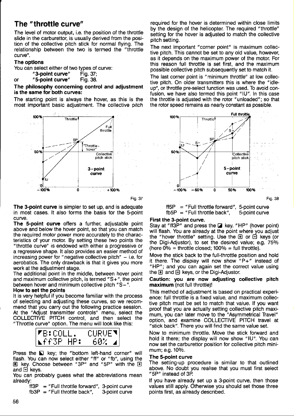
The
The
slide
tion of the collective
"throttle
level of motor output, i.e. the
curve"
position
of the throttle
in the carburettor, is usually derived trom the
pitch
for normal flying. The
stick
relationship betvveen the two is termed the
curve".
The
options
You can select either of two types of
or
The
is the same
The starting
most
"3-pointcurve"
"s-point
philosophy
curve"
concerning control
for
both curves:
point
important
basic adjustment. The collective
Fig.37;
Fig.38.
is always the hover, as this is the
curve:
and adiustment
posi-
"throttle
pitch
reouired for the hover is determined within close limits
by
the
design
of the helicopter. The required
"throttle"
setting for the hover is adjusted to match the collective
pitch
setting.
The next important
pitch.
tive
This cannot be set to any old value, however,
"corner
point"
is maximum collec-
as it deoends on the maximum oower oJ the motor. For
reason full
this
possible
collective
The last corner
throttle
ooint
tive oitch. On oider transmitters this is where the
up", or throttle
pre-select
fusion, we have also termed this
the throttle is adjusted with the rotor
the rotor
speed
remains
is
pitch
subsequently set to
"minimum
is
function was used. To avoid con-
set
first,
and the
throttle" at low
"lU'.
point
"unloaded";so
nearly
as
constant as
possible.
maximum
match it.
collec-
"idle-
In
this case
that
100fi
Throttle
SP
---:.7
Collective
pitch
stick
-
point
3
curue
IU
0+
Fig.37
The
3-point curve
in most cases. lt also forms the basis Jor the s-point
rve.
cu
The
s-point curve oflers a
above and below
required motor
the
teristics of
"throttle
regressive shape. lt
a
increasing
aerobatics.
work
The
additional Doint
maximum collective
and
between
How to
your
curve"
power
The only drawback is that it
the adjustment stage.
at
hover
the
set
It is very helpful
of selecting
mend that
At the
COLLECTIVE
"Throttle
and adiusting these
you
"Adjust
curve" ootion. The menu will look like this:
rEt:t::[tLL.
rf'f'IF HF: bül{ r
Press the
flash.
key.
@
and
E
You can
already:
Il
You
can
Choose between
keys.
probably
=
ff3P
=
fb3P
is
simpler
the hover
power
motor. By
is
endowed with either a
also
"negative
for
in the middle.
minimum
and
to
set up, and
further,
point,
so that
more
accurately to the charac-
setting these two
provides
an easier
collective
between
pitch,
is termed
collective Ditch
is
adequate
can
point
match
adjustable
you
points
progressive
method of
pitch"
gives you
"S+",
-
i.e. for
more
hover
the
"S-".
Doint
point
the
points
you
if
become familiar with the
carry out the
curves, so
following
practice
process
we recom-
session.
transmitter controls" menu, select the
PITCH
control, and then select the
[:UE:t-lEr
key;
now
"Full
"Full
"bottom
the
select either
guess
"3P"
what
left-hand
'fl'
and
'fb',
or
"5P"
corner"
using the
with
the abbreviations
throttle foMard". 3-ooint curve
throttle
back". 3-boint
curve
will
the
mean
or
E
'50c;t
-100!6
-100!6
ffsP
fbsP
First the 3-point curve.
Stay at
will flash. You
the
"fi3P"
"hover
,50c;t
"
=
Full
throttle forward". s-ooint curve
"Full
=
throttle back", s-point
press
and
are already at the
0 50%
the Z key.
point
throttle" setting. Use the
100!6
"HP"
(hover point)
where
or
El
curve
you
keys
El
Fig.38
adjust
(or
the Digi-Adjustor), to set the desired value; e.g. 750lo
(here
00/o = throttle closed; 1000/o = Jull throttle).
Move
the stick back to the
it
there.
"HP";
the
Caution:
maximum
This method
ence:
tive
proof
mum,
option, and examine COLLECTIVE PITCH travel at
"stick
and
and
E)
full
pitch
that
you
back".
The
display
you
can again
keys, or the Digi-Adjustor.
El
you
are now
(not
full throttle)!
of adjustment
throttle
must
you
is a fixed
be set to
are actually setting collective
can later move to the
There
you
Now to minimum throttle. Move the stick foMard and
hold it there; the display will now show
now set the carburettor
full-throttle
will now
set
adiusting
is
based on
value, and
match
will f ind
position
oosition and hold
"
show
P+ " instead
the correct value
collective
practical
maximum
value. lf
that
"Asymmetrical
the same
value
"1U".
for collective
experi-
collec-
you
pitch
Travel"
set.
You can
pitch
of
using
pitch
want
maxi-
mini-
mum; e.g. 100/0.
The
s-point curve
The setting-up
above.
"5P"
lf
values
points
No
instead of 3P
you
have
still apply. Otherwise
firsl, as already
procedure
doubt
you
is similar to that outlined
realise
that
you
must first
select
already set up a 3-point curve, then those
you
should set those three
described.
56
Page 59
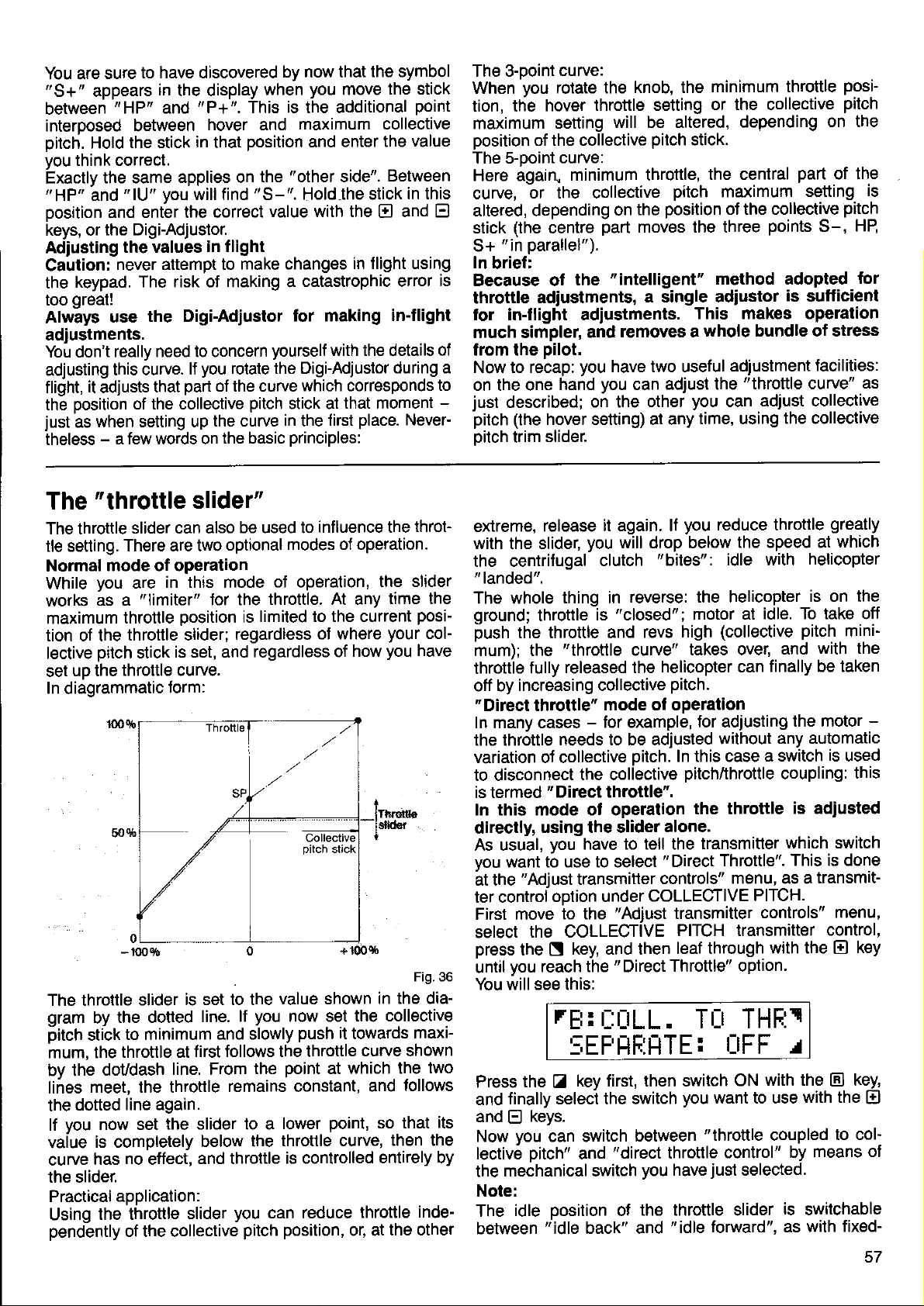
to have discovered
You are
"S+"
between
interDosed between
pitch.
vou
Exactly
"HP"
oosition
keys, or
Adjusting
Caution:
the
too
Always
adiustments.
Yoü don't
adjusting
flight,
the
just
theless
sure
in
appears
"HP"
the stick
Hold
think correct.
the same
"lU'
and
and enter the correct
the Digi-Adjuslor.
the values
never attempt to
keypad.
great!
use
really need to concern
this curve.
it
adjusts
position
when setting up
as
-
a few words on
the display
"P+".
and
in
applies on
you
will find
The risk of making a
the Digi-Adiustor
lf
part
that
of the collective
you
by now that
when
This is the additional
hover and
position
that
the
"S-".
in flight
make changes
rotate the Digi-Adjustor
of the curve
pitch
the curve
the basic
you
move
maximum collective
and enter
"other
value with the
for making
yourself
stick at
in
principles:
side".
Hold,the stick
in flight using
catastrophic error
with the details
which corresponds
that moment
first
the
the symbol
the stick
point
value
the
Between
in this
and
El
in-flight
during a
place.
Never-
The 3-ooint
When vou
tion, ttie
maximum
position
The s-ooint
Here again"
curve,
altered, depending
E
stick
"in
S+
In
brief:
is
Because ot
throttle
for in-flight adiustments.
much simpler,
of
from the
Now to recap:
to
on the one
-
just
described;
pitch
oitch trim
curve:
rotate the
hover
of the collective
br the collective
(the
parallel").
adiustments,
pilot.
(the
hover setting) at any
slider.
throttle setting
setting
curve:
minimum throttle,
the
and
you
hand
on the
part
"intelligent"
you
centre
knob, the
will be altered,
pitch
the
on
moves the three
a single adiustor
removes a
have two useful
can
other
minimum throttle
or the collective
stick.
the central
pitch
position
ad,ust the
maximum
ot the collective
method adopted
This makes operation
whole bundle of stress
adiustment
you
can
time, using
posipitch
depending
points
"throttle
adiust collective
on the
part
of
setting
pitch
S-,
is
sufficient
facilities:
curve"
the collective
the
is
HB
for
as
The
The throttle
tle setting.
Normal
While
works
maximum
tion of the
lective
set
ln diaorammatic
The throttle
gram
pitch
mum, the
bv the
lines
the
vaiue
curve
the slider.
"throttle
slider can also
There are two
mode of operation
you
are
"limiter"
as a
throttle
throttle slider;
pitch
stick
uD the
dotted
you
lf
Practical
Using
pendently
throttle curve.
slider
the dotted
by
to minimum
stick
throttle at
doudash
meet, the throttle
line again.
now set
is completely
no
has
application:
the throttle
of the collective
in this mode
position
is set, and
form:
line. From
the slider to a
effect,
slider"
be used to
optional
for the
is set to the
line.
and slowly
first follows the throttle
below the
and throttle
slider
throttle. At any
limited to the current
is
regardless
regardless of
you
lf
the
remains constant,
you
can reduce
pitch
influence the
modes of operation.
oJ operation,
ot where
value shown
now set the
push
it
point
lower
throttle curve,
is controlled
position,
which the
at
point,
throt-
the slider
time the
posi-
your
col-
you
how
towards
curve shown
and
throttle
or, at
have
rrg db
in the dia-
collective
maxi-
two
follows
so that
then the
entirely by
inde-
the other
extreme,
with the slider,
the centrifugal
"
landed".
The whole
ground;
push
mum): the
throttle
otf by
"Direct
In many cases
the throttle
variation ot collective oitch.
to disconnect
is termed
In this mode of operation
directly,
As usuä|,
vou
ät the
ter control
First move
select
press
until
You will see this:
release
throttle
the throttle and
fully
increasing collective
throttle"
"Direct
using the slider
you
want to use to select
'Adjust
option under
the collEgllvE
the
N
you
reach the " Direct
rE:
it again. lf
you
clutch
thing in
is
"throttle
released the
mode of operation
-
for example,
needs to be adjusted
the coliective
throttle".
have to tell the
transmitter
to the
key, and then
t-:uLL.
lEF HF:tlTE:
key first, lhen switch
Z
keys.
can switch
oosition
"idle
"direct
and
back" and
its
the
Press
finally select the switch
and
and
E
you
Now
lective
the
Note:
The
between
pitch"
mechanical switch
idle
you
reduce throtlle
will drop below
"bites":
reverse: the helicopter
"closed";
high
revs
curve"
'Adiust
takes over,
helicopter can
pitch.
In this case
pitchlthrottle
alone.
"Direct
controls"
COLLECIIVE
transmitter
PITcH transmitter
leaf through
Throttle" option.
the speed at
idle with
motor at
tor adiusting
the throttle
transmitter
idle. To take off
(collective
and
finally be taken
without
Throttle".
any automatic
a switch
coupling:
menu, as a
PITCH.
controls"
with the
TLr THF:1
r_rFF
with the
ON
you
want to use
between
you
the throttle slider
of
"throttle
throttle
just
have
"idle
forward", as
coupled
control"
selected.
is
greatly
which
helicopter
is on the
pitch
mini-
with the
the motor
is adiusted
which switch
This is done
transmit-
-
is
used
this
menu,
control,
key
El
r
key,
El
with the
by means
switchable
with fixed-
El
to col'
ot
Page 60

you
lt
models.
wing
transmitter
control.
controls"
You can
wish to
now select
Auto-rotation
be dedicated
One switch
tor.
When
two things:
does
1.
2.
will now
You
rotor?"
absent
oilch to
The PROFI
elegant
adiustment"
"doLLECIIVE
assign
ple, you
just'coming
PITCH
There
read the
What
There
1.
2. Assign
This should
"
hidden" under
is
To do
menu;
key and
keY.
E
will see
You
can
it is switched
lt
the throttle
sets
practising;
lor
Any limit set
transmitter
lective
require this
the servo
at
Normally, because
during
tail rotor
feature:
same switch
the
select
input to
is a further
note at the
you
have
are two
the
Set
tell
move again
this,
then on
select
the following
on collective
control end
pitch
movement
feature, adjust
only.
probably
auto-rotation,
has to be
mc 3010
you
menu, select
PITCH" input as
the switch
to that!),
"TAILROT"
possible
end ol this
to adiust:
points
"auto-rotation
"auto-rotation"
the
you
THROTTLE.
to the
"FlX-1"
the
do this,
menu
OFF
simply
to
where
and select
the
to auto-rotation,
pre-selected
to a
tor competition
thinking:
be
main rotor
removed.
offers
need to
"TAILROT",
as for auto-rotation.
"55"
then
also switchable
refinement
remember
throttle" to
you
to the
THROTTLE control.
(fixed
display:
move to the
"ldle"
as an
pitch
is lifted
available).
the
you
for auto'
make the coLLEcTlvE
section.
will
the
option and
auto-rotation
travel at
(to
collective
'what
power
mixing of collective
a very simple
move to the
switchable,
here:
"Fixed
switch.
find auto-rotation:
"Transmitter
value) option
"Adiusj
THROTTLE
adjust
selec-
the transmitter
setting
work).
make f ull col-
lf
about
and select
rotation
to this;
(idle
the
you
pitch
lf, for exam-
by
Press the
not
do
travel
the tail
torque
and
"Servo
the
then
(we're
"S5".
please
Value"
Optionsl
the
with
is
it
N
the throttle oosition
and switch
Switching
between
the
rE:
Jor the
forward
position
idle
THHr:rT
r[rFF
"auto-rotation
First:
Press the
throttle
the Digi-Adjustor;
or
Now define
Press the
using
switch
Now to the
For auto-rotation
switched
'SWITCH
TIVE PITCH"
Switch
switch
tion.
oress E
Sample
Z
setting
the auto-rotation
key, then
Sl
the E and
"S5".
That's all there
actual
ofi.
SERVO"
the'INPUT'to
to that too, but
55
To
this,
do
.
display,
throttle"
followed by
key
in the usual
0
E
problem.
the
This
inout to the
with the input
memory
r5EFI.
r[:[rLL,
r5EFt.
rFiiiEtl:
The net etfect
the throttle,
close
fixed value on,
travel.
The travels
REVERSE
is that by
set collective
and switch
adjusted
are
menu.
"idle"
is indicated
position
and back
(2,
by the
FIll-1r
E]':r
then set
El,
way with
-
is
100/o
select the
keys, as
collective
is
menu and assign
"F|XED
5: TH
a
switch:
is to
procedure:
the
auto-rotation
working
field still active
15, BK 117:
I LF;ÜT.
:
Trl I LF:r:rT.
5:
the
good
starting
switch
usual;
it.
pitch
VALUE" and assign
you
for example
input
switch 55.
in the opposite
!,5+.
-i5'+.+
operating
to a second
in the SERVO
the switch
pitch
otf, set a
of the slider
then
tr)'
prefix.
the desired
keys,
or
E
El
point.
want to use,
needs to be
move to the
"COLLEC'
the
direc-
(flashing),
r
r
S5
(variable)
collective
TRAVEL &
pitch
the
the
you
Gyro
"Suppression"
damping
override
to
and
the
There are
1.
from the
Some
which
from
tion
you
irol
ol device.
5ö
suppression
means
effect
it. This is essential,
reduce
not to counteract
pilot.
Gyros
with
transmitter.
ol these
is derived
receiver.
the
the receiver.
to
not need
do
nor a servo.
of the
unwanted
three basic
no
gyros
from the
to assign
There
reducing
gyro
as
movements due
flight
deliberate
types ot
special
These
facilities
also have
yaw
gyros
you
lf
are
"GYRO'
is nothing else
or eliminating
when the
the
gyro:
a
control signal
have only
using
pilot
gyro
is only intended
efforts
"suppression"
on the
tor
allowing
this type
to a transmitter
to say
the
wishes
gusts
to
emanating
one connec-
on this type
to
etc.,
part
of
control
effect,
gyro,
of
con'
2. Gyros
otf trom
For this
needed
the
put
ity sr,tiitcn
proportional
"Gyro
is therefore
3.
the
This is the
cerned
cial
mitter, and
the servo
gyro
whose
the transmitter.
type ot
(e.9.
"GYRO"
by the
Gyros
transmitter.
signal
name
input
suppression"
suppression"
set
with
type of
here.
is derived
this signal
outout
control"
sensitivity
gyro
a switched
channel
function;
from the
to
proportional
To
or
"G"),
you
"GYRO".
of
at the
"OFF".
gyro
with
control
"automatic
the sensitivity
from the
is then
"GYRO":
can be altered
transmitter
which
will also
This
gyro
is of
'GYRO"
sensitivity,
which we are
transmitted
this is termed
gyro
is then assigned
need a
is where the sensitiv-
is
connected.
no relevance
transmitter
YAW signal
suppression".
or switched
control
"servo"
"Automatic
here
adjustable
primarily
of the
gyro
in the trans-
gyro
to the
"automatic
is
to
out-
control
from
con-
a spe-
via
Page 61

How suppression
The transmitter
proportional
the direction
"sensitivity
the
nel. The
tivity of the
becomes.
resoonds
represented
signal,
further the stick
40 b the
generates
to the
movement). This signal
of
input" of the
gyro
less
the
to deliberate control
in Fig. 40. Fig.
corresponding
works
"suppress"
a
tail rotor stick
is moved, the more the sensF
is reduced; the
it has, and the
effect
position
gyro
movements.
40
a shows
gyro
signal
is transferred to
via a separate
less sensitive
more the model
the suppression
effect.
which is
(regardless
chan-
This
effect
practice
The system
We will suppose, as an
assigned
of
"Servo
As switch
2-oosition
it
with 3-core
travel when
is
value of 1000/o must be set at
Now all
on.
Move
and leaf through
Press N and
will see this display:
in
"transmitter
No. 6 controls
lor the Gyro function
switch
that is left is to switch
to
with 2-core lead, or a 3-position
lead. To be able
you
are using
the
to control H.
the
El
example,
control
GYRO", as already
to exploit the
a switch
the
"Transmitter
and
E
automatic suppression
Control
keys to select
you
that
=
H
you
with a 2-core lead a
"Centre"
GYRO"
described.
can use either
full
control
option.
Options"
"AUTO".
have
and
a
switch
menu
You
o
gyro
The
top and bottom
set
At the lransmitter
to control
lf a slider
suppression"
nitely
stick
is within
on the
two
has
setting
cooe
tion
usually
"GYRO".
is used,
adjustable
movement!).
the limits set
other hand,
limits set on the
proved
in
to be
is really one thing
with. Please
connection.
this
has two adjustors
steplessly
suppression,
quite
limits on
end a slider
it becomes
In this case the
you
gyro.
read the note at
the sensitivity
or a switch can be
possible
(not
to be confused
which is
on the
adequate;
gyro
"only"
can
practice,
In
too many
an
.
-
+
Fio.40 a
-
Fio.40 b
used
"gyro
infi-
facility
pilots
sec-
to
to
to
which are used
range.
to adiust
with
proportional
range of adjustment
itself. Using a switch,
switch
inlinitely adiustable
lhe end of this
between the
this latter
for most
rH:
tj'T'Fjt:t
:;I-IFF'F:E:;:;:
Press the
and that's
Tip:
Connect a servo
RO" output
able to see
With switch H set
tre, the servo
the stick, the servo
ate
point,
regardless
lf
this end-point,
stick:
lf necessary:
Depending
the
when the tail
maximum, and
In this case
ment"
through
key, then
sron.
Supplementary
1. Minimum
During
ner values"
suppression),
switch
beginning
lf the
carry
method:
Move
suppression
(you
doing
(see
its movement
you
now set switch
it receives the signal
suppression
gyro
it
'TRAVEL
can do it separately
is
Fig. 41).
key, then E .
A
it.
(instead
for this setting up
exactly how the suppression
will be at one end-point.
ol which side the stick
and is not affected
your
on
rotor stick is at centre,
it reduces as stick
you
menu. Select
you
until
You have
E.
notes
and maximum suooression
this description
for
suppression
between
H, were set on the
of the section.
does
the transmitter,
out at
to the
REVERSE", and set the
+
you
as
selting
the corner
"OFF"
gyro)
of a
process.
to
works
need to
reach
not otfer this
"Servo
and the tail
OFF
will run towards
proportional
H to ON, the servo
"gyro
particular gyro,
"the
wrong way round";
move to the " Servo
"TRAVEL
"Servo"
now " reversed"
we have assumed
(maximum
which
wish.
you
gyro
itself, as explained
feature, or
then there
adjustment"
When
for both directions!),
values for
HUT|_].
üFF
is replaced by
lo the receiver
to the stick
is moved to.
by movement ol
fully suppressed".
it may turn out that
suppression
detlection
REVERSE" and leal
+
No. 6. Press the
can move using
you
I
r
"ON";
"GY-
You will then be
works.
effect
rotor stick at cen-
you
lf
adjust the
gyro
now
oper'
the other end-
position;
runs
straight
is at a
increases.
adiust-
gyro
suppres-
want to
of
you
all
"cor-
at the
gyro
travel
that the
and minimum
you
is
an alternative
menu, select
"travel"
suppression
to
the
i.e.
Sl
the
are
59
Page 62
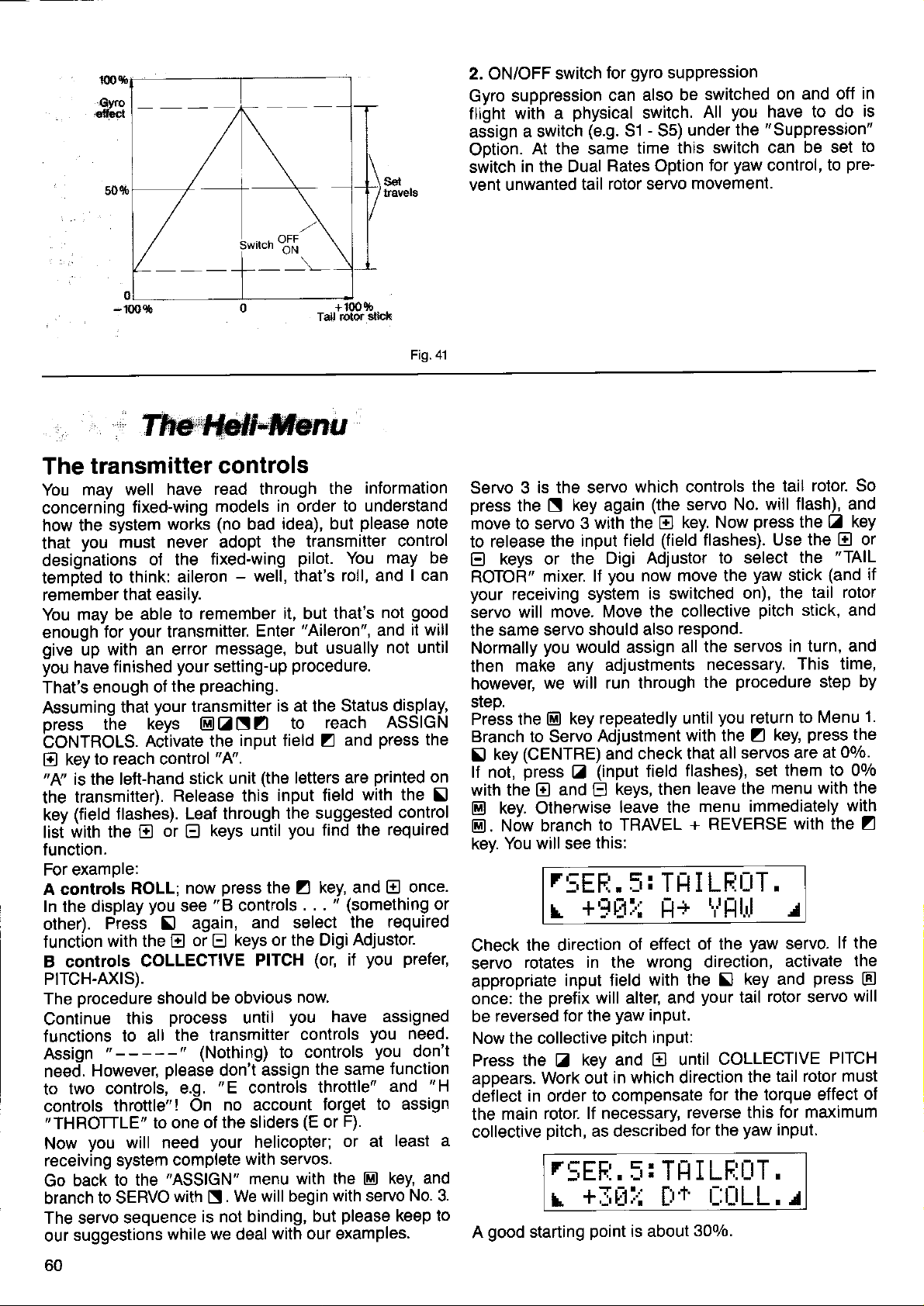
2. ON/OFF switch
Gyro suppression
with a
flight
assign
Ootion.
switch
vent unwanted
a switch
At the same
in the Dual
for
can
physical
(e.9.
Rates Option
rotor servo
tail
gyro
suppression
also be
switch.
Sl - 55)
time this
switched
you
All
under
switch can
for
movement.
have to do
"Suppression"
the
yaw
control,
on and off
be set
pre'
to
in
is
to
-100s
The
You
concerning
how the
that
desighations
tempted
remember
You may be
enough
give
you
That's enough
Assuminq
press
CONTROLS.
El
the
function.
A controls
transmitter
may well
system
you
must never adopt
to think:
for
with an error
up
finished
have
that
t-he
to reach control
key
"A"
is the left-hand
transmitter).
(field
key
list with
For examole:
In the display
other).
f
unction
B controls
PrTCH-AXrS).
The orocedure
Continue
functions
Assign
need.
two controls,
to
controls
"THROTTLE"
Now
receiving
Go
branch
The servo sequence
our
flashes).
the
Press
with the
"-----"
However,
throttle"! On
you
system
back to
to SERVO
suggestions
have read through
fixed-wing
works
of the
aileron
easily.
that
able to
your
kbys
Activate the
E
ROLL;
you
COLLECTIVE
this
to all
to one
will need
the
remember
transmitter.
your
preaching.
the
of
transmitter
vour
EIZ
stick unit
Release this
Leaf through
or
El
now
see
again,
5l
or
El
should be
process
the transmitter
(Nothing)
please
e.g.
complete
'ASSIGN"
with
is not binding,
while we deal
Tad rolor
controls
models in order
(no
fixed-wing
message,
setting-up
"4".
keys until
press
"B
keys or the Digi
E
obvious
don't
"E
no account
of the sliders
your
We
S.
idea), but
bad
the transmitter
pilot.
-
well, that's
it,
but
"Aileron",
Enter
but usually
procedure.
is at the Status
N Z
input field
controls
until
to
(the
letters are
input field
the suggested
you
the Z key, and
. . .
and select
PITCH
assign
controls
helicopter;
with servos.
menu with the
will begin with servo
(or,
now
you
controls
controls
to
the same
(E
but
with our examples.
+100q6
3üat(
Fig.41
information
the
to understand
please
You
roll, and
that's
reach
and
Z
with the
find the
"
(something
the
Adjustor.
you prefer,
if
have assigned
throttle
forget
F).
or
or at
El
please
note
control
may be
lcan
good
not
it will
and
not until
display,
ASSIGN
press
the
printed
control
required
once.
E
required
you
need.
you
don't
function
to assign
least a
key, and
No.3.
keep to
Servo 3
press
to release
El
your
servo
the same
then
srep.
on
with the
fl
or
the
move to servo
keys or the
ROTOR"
receiving system
will move.
Normally
make any
however,
Press the
Branch to servo
(CENTRE)
key
E
lf not,
@
@.
kev.
Check
servo
appropriate
once: the
be
Now the collective
Press
appears.
deJlect
the
collective
A
press Z (input
key. Otherwise
Nöw branch
You will see
the direction
rotates in the
reversed
the
in order
main
good
starting
is the servo
key again
N
3 with the
the input
mixer. ll
servo
you
would assign all
we will run through
key
E)
and
El
r5EFl.
+'-+Etil
r
input field
prefix
for the
key and
Z
work out
rotor. lf necessary,
pitch,
r5EF:.
+f,tlr:i
r
which controls
(the
servo
key. Now
El
(field
field
Digi Adjustor
you
now move the
is switched
Move the collective
should also
adjustments
repeatedly until
Adjustment
and check
keys, then
E
leave the
to TRAVEL
this:
respond.
with the
that all
flashes), set
field
5: TH I LFlr:rT.
Fl+
of effect
wrong direction,
with the
will
yaw
pitch
in which direction
to compensate
as described
and
alter,
input.
input:
El
until
i: TIl
[tt'
point
is about
the tail
No. will flashl and
press
flashes). Use the
to select
yaw
on), the
pitch
the servos
necessary.
procedure
the
you
return to
Z
servos are at
leave the
menu immediately
+ REVERSE
t,illllr.l
of the
your
reverse
for the
yaw
key and
f)
tail
COLLECTIVE
the
{or the torque
this for maximum
yaw
rotor. So
the
El
the
(and
stick
tail rotor
stick, and
in turn, and
This time,
step
Menu
press
key,
them to 00/o
menu with the
with the
J
servo.
activate
press
rotor
servo
PITCH
tail rotor must
effect
input.
I LF:ÜT,
t-:t-]LL.r
300/0.
key
or
E
"TAIL
if
by
1.
the
Oo/o.
with
Z
lf the
the
@
will
of
60
Page 63

Your tail
Z
FIXED VALUE
You only
which
this under
VALUE
leave it unchanged.
THROTTLE SERVO
Let's
menu
2
release
function using
set up
select
we
you
lf
torward, and
throttle servo should
Here
SCIECT thE
Press
"TRANSMITTER
Select OPTIONS,
Using
Release
you
preferred,
position
full throttle back
releasing the
curve
For a 3-ooint
And for a s-ooint
Note here
throttle.
Now
This
major
We will describe
you
lf
at
rotor mixer
key, then
move on to the
and
will
again
can select
tU
HP = Hover Point
lU = ldle Uo
S-
HP
S+
to the
is the only area
Schlueter
Heim
3-point
4-point CPM
3-point
present.
El).
need this
continues
with the
with the
ditferences.
wish, skip
"Auto-rotation".
"OFF"
is
Assign
inout field, and select the
the
a mixer circuit
"DYN.
with
stay
push
now
operate the
we need to set a basic
THROTTLE CURVE.
return to Menu
to
@
the
N
the input
using
with the
curve:
=
tdte
Throttle
=
Pre-idle
=
Hover Point
=
Pre-max. throttle
Throttle
that the throttle
rotor head
CPM
CPM
requires a lurther
if
to rotate during auto-rotation.
("SWITCH
key
@
"Assign
to
the E and
THROTTLE" here.
THROTTLE.
the throttle slider
move.
CONTROU'
then the Collective
selector key,
f ield with
a 3- or s-point
E
key
E
-
input field
help of the collective
Up
maximum
curve:
point
maximum
in which
5 difjerent
go-degree,
l2o-degree,
the examples
SCHLUETER
means
That
mixers).
Io Menu
select:
Now
no rotor
Return to
2, to ASSIGN
Menu 1 with the
input
your
helicopter
The default
SERVO"
next servo. Leave the
move through
and
servos". Select
keys. Later,
E
for aerobatic
collective
1, then branch
move on to
(ff
!
or
more details
keys, set
E)
=
(ff
full throttle
you
can set up
(servo
point
(servo
slider should
model helicopters
examples:
with virtual rotation
with virtual
with virtual
which are
head mixing
ASSIGN
ANd
has a tail
menu). For
Menu 1,
"THROTTLE"
if
flying,
For our experiment
(the
usual control)
pitch
adjustment,
adjustment
Pitch control.
similar
3 or
throttle
the full throttle
forward, lb
page
on
pitch
stick.
travel)
travel)
be set to
of no interest
(no
key, then
El
SERVOS.
(press
for FIXED
Adjustment
you
you
slick,
"CURVE".
56).
the throttle
rotation
rotation
the
rotor
More on
now
Menu
servo
curve as
electronic
6,
wish to
would
your
and
to the
menu.
flashes)
=
After
full
exhibit
move
Servo
Servo
Servo
Naturally this set-up
servos
Return to Menu
Adjustment,
Check
the approximate
appropriate
and
E
corresponding
can
necessary.
No. 1 controls
No. 2 controls
No. 4 controls
will only
to the corresponding
l with the
TRAVEL +
the direction of
input field with
(holding
keys
E
end-points)
reverse any of the servos
rotation oJ the servos
servo
HEIM
When
are
ing
Return to
and
Select
The two
puts
the
ment, TRAVEL +
Operate
the
corresponding
correct direction
we
speak
referring to the classic
pitch-axis
on to ASSIGN SERVOS.
(Assign)
Servo
Servo
Servo
1 + 4, and
key to return to
@
First select servo
-
and check
Reverse
Now look at servo
lective
reverse the collective
Now
rotation of one or both
pitch
for the two roll servos
ROLL stick and
3-point
rocker
Menu 1 with the
No. 1 controls
No. 2 controls
No. 4 controls
roll
servos
the collective
it il necessary.
should be
linkage,
90'degree
The 90-degree
the distribution
since
will describe the application
ertheless,
We assume
Menu 1 with the
and then
There
Once
Release
Select
Release the
Z ,
Repeat the
we
that
via ASSIGN to
you
assign the servos
Servo
Servo
Servo
No. 1 controls
No. 2 controls
No. 4 controls
more, to
the SERVO
the servos
Controls
and select
process
HEIM rotor head
of a
(see
the servos as
are connected
pitch-axis
the
Menu 1, then on to Servo
REVERSE.
l and the Collective
pitch
the direction
4. lf the direction
pitch
watch the servos.
servo,
then the
of rotation.
"HEAD-MlX"
arrangement
of forces
you
are at
key, then to
El
remind
input line with the selector
in turn
field
HEAD-MIX
with the second
ROLL-axis
PITCH-axis
COLLECTIVE
work if
receiver output
key, then
El
REVERSE.
travels.
the
HEIMHEAD
PITCH
HEIMHEAD
wrong, switch to
servos
ASSIGN SERVOS.
HEAD-MIX
HEAD-MIX
HEAD-MlX
you:
To
set
S,
transmitter controls
for both sides
version
page
also
key, then move to
E]
tollows:
servo
stick
of rotation of the servo.
input.
and the
is incorrect, select
roll input, and set
is swiftly
is very inefficient.
the Status display.
Menu 2 with the
lollows:
as
with the E or
again
with the
PITCH
you
connect
go
this, activate the
do
the travels
of centre.
with the
(HEIMHEAD)
with the freeJloat-
55).
to the
-
look at servo
with the selector
receiver out-
to output
Pitch input.
of rotation
this servo and
roll input: operate
lf the direction
losing
in
E
servo, and so
the
sockets.
to
Servo
and set up
with the
at the
You
key
trl
we
Menu 2
2.
Use
Adjust-
1 only
for col-
ot
the
the
popularity
Nev-
detail.
to
Move
key,
El
key
[1.
keys.
E
key
E
key.
on.
or
if
Page 64
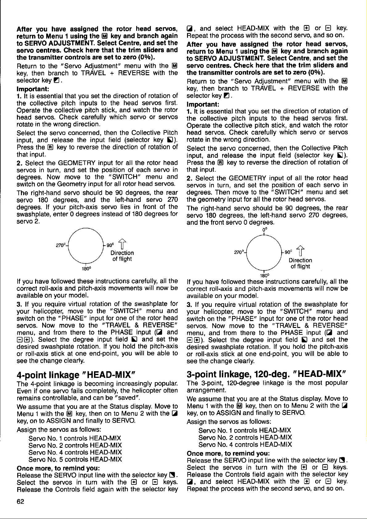
you
After
return to
to SERVO
servo
the transmitter
Return to the
kev then branch
seiector
have assigned
Menu 1 using the
ADJUSTMENT. Select
centres. Check
controls are set to
"Servo
Adjustment" menu
to TRAVEL +
key Z .
lmportant:
you
1. lt is essential
the collective
Operate
the collective
head servos. Check
in
rotate
Select
the
the servo
input, and
Press the
input.
that
2. Select
servos
the GEOMETRY
in turn, and
degrees.
switch
The
servo
degrees.
on the Geometry
right-hand servo should be
180 degrees, and the
lf
swashplate,
2.
servo
you
lf
have
correct
available
3. lf
your
roll-axis and
on
you
require
helicopter, move to the
switch on the
servos.
Now move to the
menu, and
EEI).
Select the degree
desired swashplate
roll-axis stick at one
or
the change clearly.
see
4-point
4-point linkage
The
if one servo
Even
remains controllable,
We assume
Menu
key, on to
Assign the servos
Once
Release
Select
Release the Controls
l with the
ASSIGN and finally to SERVO.
Servo
Servo
Servo
Servo
more, to remind
the SERVO
the servos
that
pitch
inputs to the
carefully which servo
wrong direction.
concerned, then the Collective
release the input field
key to reverse the direction of
tr
set the
Now move to the
your pitch-axis
enter 0 degrees
/\z\
,t0"1
\ /
\-,-/
1800
followed these instructions carefully,
oitch-axis
your
model.
virtual rotation of the swashplate
"PHASE"
from there
rotation.
linkage " HEAD-MlX"
is
lails
and can be
you
that
No. 1 controls
No. 2 controls
No. 4 controls HEAD-MIX
No. 5 controls
are at
key, then on to Menu
E
as follows:
input line with the selector
in
field again
the rotor
key and branch again
El
head
servos,
Centre, and set
here that the trim sliders
(Oo/o),
zerc
with the
REVERSE with the
set the direction of
head
pitch
stick, and
(selector
rotation of
servos
watch the
or
servos
key
rotation of
input for all the rotor
position
"SWITCH"
input for all
90
of each
rotor head servos.
degrees,
servo in
menu and
the
left-hand servo
servo
lies in front oJ the
instead of 180 degrees
ro.
ll
f
Direction
flight
of
all the
movements will
"SWITCH"
for one oJ the rotor
inDut
"TRAVEL
to the PHASE
lield
input
you
lf
end-point,
becoming
completely,
hold the
you
increasingly
the
"saved".
the Status display.
& REVERSE"
input
\l
will be able to
helicopter often
now be
menu and
(Z
and set the
pitch-axis
popular.
Move to
2 with the
HEAD-MIX
HEAD-MIX
HEAD-MIX
you:
key
turn
with the
with
or E keys.
El
the selector
the
and
El
first.
rotor
Pitch
5l).
head
rear
270
for
for
head
and
Zl
N.
key
and select
01,
Repeat
After
return to
to SERVO
servo
the
you
Menu 1 using the
ADJUSTMENT. Select
centres. Check
HEAD-MIX
process
with
have assigned
the transmitter controls
Return to the
key,
then branch
selector
key Z .
"Servo
Adjustment"
to TRAVEL
with the
second servo, and
the
the
E
here that the trim slide6
are set to
lmportant:
you
1. lt is essential
the collective
Operate
head
rotate in
Select
the collective
servos.
the
the servo concerned,
that
pitch
Check carefully
wrong direction.
input, and release the
Press the
input.
that
El
key to
2. Select the GEOMETRY
servos
degrees. Then
the
in turn, and set the
move to the
geometry
input
set the direction
inpuls to the head servos
pitch
stick, and
input field
reverse the direction
input of all
position
"SWITCH"
for
the rotor head servos.
all
The right-hand servo should
servo
and
lf
correct
available on
3.
your
switch on
servos.
menu, and
EE)).
desired
180
degrees,
the front servo 0 degrees.
you
followed these instructions carefully,
have
roll-axis and
your
you
lf
require virtual
helicopter, move to the
"PHASE"
the
Now move to the
lrom
Select
swashplate
or roll-axis stick at
see the change
3-point
The 3-point,
linkage, 120-deg.
12o-degree linkage
the left-hand servo
o0
/\z\
27ool
\ ,/
\--.'
18oo
oitch-axis
model.
rotation of the swashplate
input lor one ot the rotor
"TRAVEL
there
to the PHASE
the degree input
rotation. lf
one end-point,
clearly.
arrangemenr.
We
assume
1 with the
Menu
key, on to
ASSIGN and
that
you
key, then on to
E]
Assign the servos as
Servo No. 1 controls
Servo
Servo
Once more, to
Release the SERVO
Select
Release
Z
,
Repeat the
No. 2 controls HEAD-MIX
No. 4 controls
remind
input line with the selector
the servos
in turn with the
the Controls field again
and select
HEAD-MIX
process
with the second
are at
lollows:
the Status display.
linally to
HEAD-MIX
HEAD-MIX
you:
El
or
E
key.
so on.
rotor head servos,
key and branch again
Centre, and set
and
(0%).
zero
menu with the
+ REVERSE
with
of rotation of
first.
watch the rotor
which servo or servos
then the Collective
(selector
Pitch
key
!).
of rotation of
the rotor head
of each servo
menu and set
be 90 degrees,
the rear
270 degrees,
fto"
U
Direction
of flight
all the
movements
"SWITCH"
will now
menu and
head
REVERSE"
&
(Z
input
and
field S and set the
you
hold the
you
pitch-axis
will be able to
"HEAD-MlX"
or
popular
Move to
key
keys.
E)
key.
E)
is the most
Menu 2 with the
SERVO.
El
with the selector
with the E or
servo, and so on.
the
El
the
in
be
lor
Z
B.
key
62
Page 65

After
you
have assigned
return to Menu 1 using the
SERVO ADJUSTMENT.
to
servo centres. Check
the transmitter
controls are set
Return to the " Servo
then branch to TRAVEL +
key,
selector
key Z .
the rotor head servos,
key and branch again
@
Select Centre, and set
here that the trim sliders
to zero
Adjustment" menu
REVERSE with the
lmportant:
lt is
1.
essential
the collective
Operate
head servos.
the collective
Check carefully which servo
you
that
pitch
inputs to the
set the direction
head
pitch
stick, and watch the
rotate in the wrong direction. Select
cerned, then the Collective
(selector
the input
field
reverse the direction of
Select the GEOMETRY
servos
degrees.
the
The rioht-hand servo
servo
in turn. and set the
Move
geometry
-180
the
to
input for all the
degrees and the
"SWITCH"
should be 60 deqrees.
Pitch input, and
key
Press the
!).
rotation of that input.
input of all the
oosition
of each
menu and switch
rotor head
left-haid
oegrees.
the
and
(00/o).
with
the
El
of rotation of
servos
first.
rotor
or
servos
the servo con-
release
key to
E
rotor head
servo in
on
servos.
the rear
servo
300
300,,//
\ ,/ Direction
\--./
1800
you
have followed these instructions caretully,
lf
correct
available
3.
your
switch on the
servos. Now
menu, and
EE).
desired swashplate
or
see
This
required for
els according
tion
angle
roll-axis and
your
on
you
lJ
require virtual rotation of the swashplate
helicopter, move to the
"PHASE"
move
oitch-axis
model.
to the
from there to the
Select
the
degree
rotation. lf
roll-axis
at one end-point,
stick
the change clearly.
setting-up
provided
jig,
or check the settings by eye.
procedure
your
model. You can now set up the trav-
your
to
by the
\60"
f
of flisht
all the
movements will now be
"SWITCH"
inout lor one ot the rotor head
"TRAVEL
menu
REVERSE"
&
PHASE iHput
field
input
you
you
produces
own experience
and set
S]
hold'the
pitch-axis
will
be
the
or the informa-
helicopter manufacturer. Use an
lor
and
(Z
and
the
able to
program
Teacher/Pupil operation
"buddy-box"
control
model longevity.
of
system)
a radio-controlled
transmitter each,
lead,
Order
radiates an
a signal, but
ates
quency;
No. I 5121. Only
RF
instead
mitter through the cable,
For this
come
nals at all!
transmitter,
reason it is
from the
lf mixed
these signals
is
the best
model, Jrom the
"Teachet"
inter-connected by
signal.
The
it is not broadcast at
it is transferred to the
where it
vital
pupil's
transmitter
signals
twice.
Assign the transmitter
controls of the
mitter as follows:
A controls
e.g.
aileron B controls
and continue:
Servo
No. 1 controls
aileron Servo
elevator, etc.
you
lf
mc, be sure
pupil's
The
module.
switched
The teacher's
Teacher/Pupil
nate between
control",
are using a difterent
to
switch
transmitter.
pupil's
transmitter does
However,
if
one
out of circuit
when the
transmitter has to be
switch, by
"pupil
means of which he can alter-
has control" and
and can therefore
threatens.
(sometimes
known as
the
method of learning to
and
point
"Pupil"
view
of
have one
the Teacher/Pupil
the teacher's transmitter
pupil's
transmitter
gener-
Radio Fre-
teacher trans-
"processed".
is
that only
are sent
would be
basic signals
-
no mixed
sig-
to the teacher's
processed
pupil's
trans-
throttle, etc.
No. 2 controls
transmittet e.g.
mixers
all
"OFF"
not require an
ROYAL
at the
RF
is fitted, it is automatically
lead is
plugged
in.
fitted with a
"teacher
has
intervene whenever danger
Teacher/Pupil operation
main
four
sary, and
One
is not recommended
special advantage olfered
transmitter
just
rudder, or
terred, so that the
functions
stick
is that individual control
just
rudder
pupil
is basically restricted to the
(more
and elevator
can
srages.
We will assume
3010 transmitter
from now on that the
is the
"teacher"
The tollowing types can be
mitter:
Naturally, other
other MULTIPLEX
any
"diagnosis"
PROFI mc 3010 /3030 transmilters;
transmitter
(closed
loop, or direct
socket.
These
90", Cockpit"
include " ROYAL
and
mc";
"
EUROPA-Sprint".
The teacher transmitter
Teacher/Pupil switch.
be used:
can
ON/OFF switch,
switch,
The best
bays
must
short toggle Order
locations for
1,
6,
Z
connected
be
connector;
round
you
switch itself
page
on
66
long toggle Order
(see page
12
page
see
insert the connector,
is
the
under
The lollowing types of switch
No. 7 5697
"ouick
5).
inside
right way round.
"Testing
the
7. lt
does
the lransmitter
The two transmitters are
Teacher/Pupil
simply
plugged
Caution:
lead, Order
into both transmitter
ROYAL mc Co-Pilot lead Order
The
5122 cannot be used!
than this
in
any
by the PROFI
is
case).
unneces-
mc
functions - e.g.
-
"learn
can be trans-
ropes" in
the
PROFI mc
unit.
used as the
pupil
which is f itted with a
servo control)
"COMBI"
must be
"COMBI
and
fitted with a
No. 7 5698 ON/OFF
access"
The
to the switch are
plug
from the switch
transmitter to the
not matter which
but make sure that
This is
explained
controls".
inter-connected by
No.8
5121.
The lead
charge sockets.
3010
easy
trans-
"US"
way
the
the
is
No. I
AE
Page 66
1. Essential adjustments to the
Pupil
transmitter
it is not a PROFI mc
a.) lf
the transmitter to
set
suming that
off any
lorce.
Set all the transmitter stick trims to centre.
At this
(=
bers
mitter sticks. To do this, operate the
at the
outDut
Note down these
them
It is not
or swap
whether the
ter:
(collective pitch)
erences are taken care of later when the Teacher
transmitter
b)
Here
to
To do this
seouence
You
receiver which
it is connected to.
later when
roll) right"
For PROFI mc
the setting up
the transmitter to " Pupil mode".
set
will
it has
mixers, Dual Rates
point you
666nna1
necessary
plugs
pupil,
is
set uD.
move
@EaZ
see the
--
two transmission modes). Switch
should also check
numbers)
four
setting up the Teacher transmitter.
to
over. Similarly
lor example, f lies
"
lett"
ot
right" ot " left". These individual
3010
procedure
to the
.
following
FUFIL f,liltiE
I:;
Press Z and then
That's all there is to it. Leave the menu and return to
the Status display
When
later,
In the top line ol the display the model name and
'Pupil"
ter's way of telling
This
agaln
meantime,
Here again,
nel number) operates
find this
there
"Servo
controls
2.
you
wish to return to
switch
mode is maintained
you
back in exactly the same way.
will tlash alternately. This is the transmit-
-
even if the transmitter is switched otf in the
you
information in the
will find something like this:
No.3 controls
ELEVATOR", and so on.
Essential
tr.
with
will need to check which servo
adjustments
3010/3030 transmitter
"PPM"
servo
channel
reverse
i
transmitters:
transmission mode
which may
etc.
which
are controlled by the trans-
sticks
moves
numbers;
the transmitter controls,
it makes no
the same applies to
is
simple;
'"PUP|L"
display:
which receiver
and
you
"aileron
you
menu, with the
--
: r_rFF
'OFF'
El E El
"normal
you
that
until
which
control
RUDDER";
r
is replaced
tlight operations"
it is in
"Assign
"Pupil
it is
switched
function. You can
servos" menu;
"Servo
to the
(as-
in
be
num-
servo
and check
will need
difference
(helicop-
"throttle
pref-
just
need
key
"ON".
by
mode".
out
(chan-
No.2
Teacher transmitter
Here things
mc 3010 transmilter
you
are
You
can
pupil
and
example,
teacher
from his usual ways.
get
forced to choose between them:
in tact arrange the sticks of the teacher
transmitters
the
"aileron
little more
a
gives you
pupil
can
right"; neither needs to depart
complicated;
many options that
so
in
a diflerent
"aileron
fly
the PROFI
layout. For
left", and the
Even this is not so terribly difficult
need to know
There is
Teacher transmitter: the
You reach
You will
is how
a special
this
this:
see
.'+l:ll
your pupil
menu lor these adiustments
"TEACHER"
menu with the key sequence
LEE:
usually llies.
.'+:;Ft-tI
to set up; all
menu.
@ tr N A
L
you
in the
.r+FtLl[r[rE,r+ELEI-1fi
Note:
"arrangement"
The
functions in this menu
has
been selected
may
therefore
example, the ailerons may be in a different
the model is a helicooter the control functions will
appear as collective
you
Now
servo) numbers of the
over by the 4 main control
For
before
you
lf
"1";
Channel
taken
transmitter, and
stick.
you
lf
taken over, and control of ailerons
teacher,
lf it turns out that the control tunction is reversed
when the
key while the channel number
" - "
black background
the direction of rotation is reversed when it is
over".
Assign
same
The four
the
Caution:
When
Teacher/Puoil switch to
won't work at all!
And by the by ...
It is vital to determine
the teacher's transmitter controls
natively,
up
really
We recommend that
ments
field. At the take-off
atmosphere
You will undoubtedly have to change something or
other
to transfer
pupil.
have to tell the transmitter which channel
example,
"+
rl I LEE0H' starts flashing.
press
now
press
again, and
(or
1
over
leave the
pupil
arrow
remaining three control Junctions in the
the
way.
"arrow
four
control
trying out the system, do
you
the system.
"understand"
several
at the flying site, tor example, when
more
as the
look
slightly different
press
the
2,
etc.)
as the aileron signal in the teacher
"replaces"
slash unchanged,
is in control, simply
will
be
(inverse
keys"
function assignments in the menu.
can
iust
(although
times
quite
as
or
type of the four main stick
and
are based
"Teacher"
pitch,
roll,
pupil's
functions.
the
Z
key, the
El
it
becomes
in the
replaced
video); this
are each
"ON":
{irst
which channel
try everything out
in that case
what was
you
belore
strip
peacetul
fewer control tunctions to the
on the model which
model. The menu
in
some cases.
"corner";
pitch
system are to be taken
key. The
slash
"2",
pupil
the teacher's aileron
is
by a
used to activate one of
not forget to
otherwise the svstem
which function. Alter-
going
practise
you go
you
as in
yaw.
and
slash sign
is replaced by a
This means:
etc.
transmitter will be
nothing will be
remains with
press
flashing. The
still
white
indicates
when
you
on).
these
to the flying
will not find the
your
the
arrow on a
"taken
set
number
you
would not
adiust-
workshop.
you
want
For
(=
(i)
the
E
that
the
on
set
.
if
64
Page 67
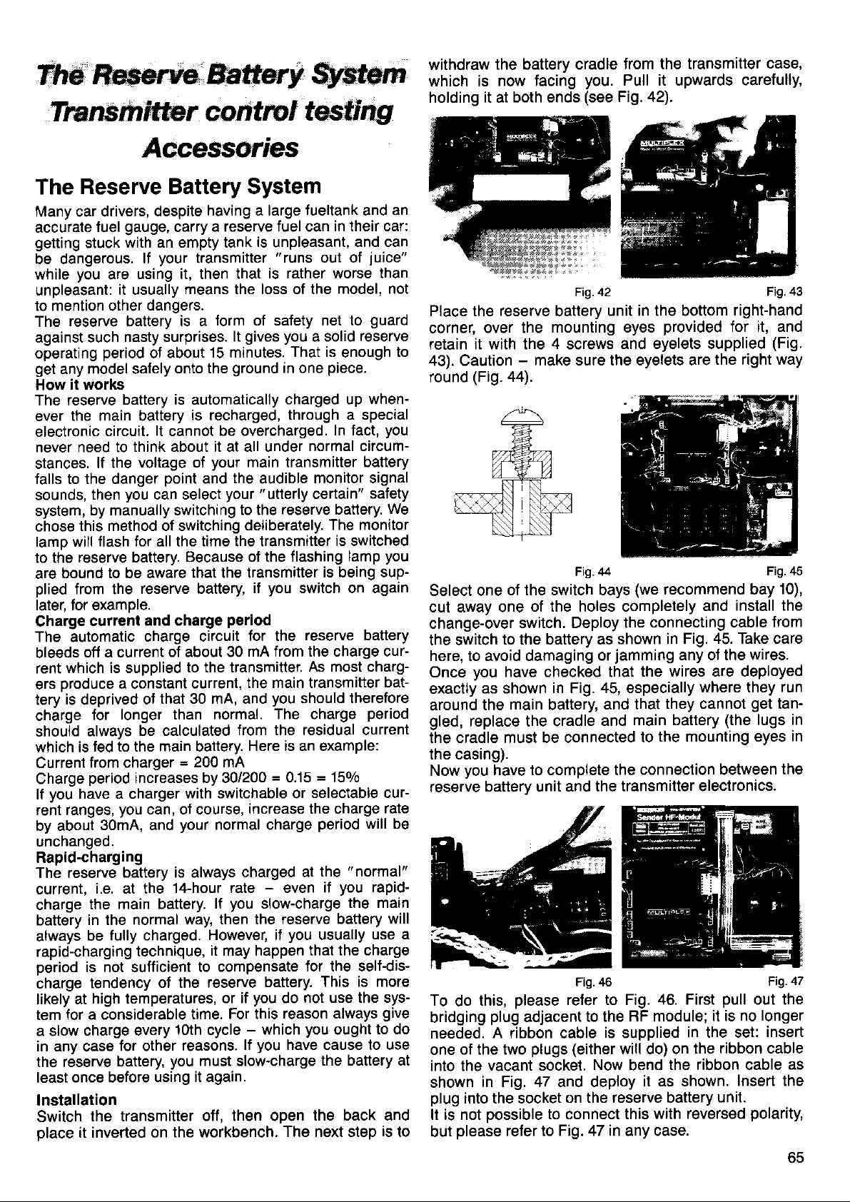
The
ns m itf-r; r c o
Tn
Rserve
Battery
$ctem
ntrc I testrhgl
withdraw the
which is
holding
now tacing
it
at both
battery cradle
you.
(see
ends
Fig. 42).
Jrom the transmitter
case,
Pull it upwards caretully,
The
Many car drivers,
accurate
getting
be dangerous.
while
unpleasant:
to mention other
The
against such
operatrng
get
How
The reserve
ever
electronic
never need to
stances.
falls to the danger
sounds,
system,
chose
lamo will
to the
are
plied
later. tor examole.
Charge
The automatic
bleeds
rent
ers oroduce
tery
charge
should
which is
Current
Charge
lf
rent ranges,
by about
unchanged.
Rapid-charging
The reserve
current,
charge
battery
always
rapid-charging
period
charge
likely at
tem
a slow
in any case
the reserve
least
lnstallation
Switch
place
Reserve Battery System
despite
gauge,
fuel
with an empty tank
stuck
you
are
reserve battery is a
period
any model safely
it works
the main battery
circuit.
lf the
then
by manually switching
this method of switching
flash for all the time the transmitter
reserve battery. Because
bound to be aware
from the
current
oft a current
which is supplied
is
deprived
for
always
fed to the main battery.
from charger
period
you
have a charger
30mA, and
i.e. at the
the
in the normal
fully charged.
be
is not sufficient
tendency
high temperalures,
for a considerable
charge every
once before
the transmitter
it inverted on
your
lf
using it, then that
it usually
dangers.
nasty surprises.
of about
battery is automatically
lt
think about it at all under
voltage of
you
can select
reserve battery
and charge
charge circuit
a constant
that 30 mA, and
ot
longer than
be calculated
increases by 30/200
you
can, of course,
battery is always
main battery.
technique,
oJ the reserve
for other
battery,
using it again
having a large lueltank and
a reserve fuel can
carry
is
unpleasant,
transmitter
means the loss of the
form of safety net to
15 minutes.
onto the
cannot
point
of about 30
to the transmitter.
=
with switchable or
your
14-hour rate - even
way, then the
10th cycle
reasons.
you
the workbench.
ground
is recharged,
be overcharged.
your
and
your
that the transmitter
period
current,
normal. The charge
200 mA
normal charge
you
lf
However, if
it may happen
to compensate
or if
time. For this
must slow-charge
oft, then open
"runs
is rather worse than
gives you
lt
That is
in one
charged up
through a special
main transmitter battery
the
audible
"utterly
reserve battery.
to the
deliberately.
of the flashing
you
if
for the
mA from the charge curthe main transmitter
from the residual current
Here is an example:
increase the charge
charged at
you
-
lf
switch on again
you
should therefore
=
0.15
slow-charge
reserve battery
you
battery.
do
reason always
which
you
have cause to use
The next step
an
in their car:
and can
out of
a solid
normal circum-
monitor signal
certainf'
is being sup-
reserve battery
As most charg-
=
selectable cur-
period
the
if
usually
that the charge
for the self-dis-
This is more
not use the sys-
you
the battery at
the back and
juice"
model, not
guard
reserve
enough
piece.
ln fact,
The monitor
is switched
lamp
150/0
"normal"
you
the main
ought
to
when-
you
safety
We
you
bat-
period
rate
will be
rapid-
will
use a
give
to do
is
to
42 Fig.43
Fig.
Place the
corner,
over the
reserve
battery
mounting eyes
unit in the bottom
retain it with the 4 screws
-
43). Caution
round
(Fig.
Select one
cut away one
change-over
the switch
make
44).
of the switch bays
of the holes completely
switch. Deploy the
to the battery as
here, to avoid damaging
you
Once
exactly
around
gled,
cradle must be connected
the
have checked that
as shown
in Fig. 45, especially
the main battery,
replace the cradle
the eyelets are
sure
Fig.44
shown in
jamming
or
and that
and
the casing).
you
Now
reserve
To
bridging
needed.
one
into the
shown
plug
It is not
but
have to complete the
battery unit and the
Fig.46
do
this,
plug
please
adjacent
refer to Fig.
to the
A ribbon cable
plugs
ot the two
(either
vacant socket.
in Fig. 47 and deploy
into the socket
possible
please
refer to Fig. 47 in any case.
on the reserve battery
to connect this
is
will do) on
Now
right-hand
provided
and eyelets supplied
for it, and
(Fig.
the right way
Fig.45
Fig.45
(we
recommend bay
install the
and
connecting cable
10),
lrom
Fig. 45. Take care
any ot the wires.
the wires are deployed
where they run
they cannot
main battery
the mounting eyes
to
connection between
get
(the
tan-
lugs in
the
transmitter electronics.
Fig.
46. First
RF module; it is
supplied
pull
out the
no longer
in the set:
insert
the ribbon cable
the ribbon cable
bend
it as shown.
Insert the
unit.
with reversed
polarity,
in
47
as
oc
Page 68

Now check
that the
mechanics.
everything one
ribbon cable
and
vou
last time. Convince
cannot obstruct
done. Close
are
yoursell
the stick
the transmitter.
this time on
From
transmitter
that the reserve
sure
as often as
please
be sure
possible,
battery
to slow-charge
so that
you
is fully charged.
your
can
be
The
All the sliders and
in
wrong
will be
transmitter
under
you
descriptive
This
1.
2. You can
"Transmitter
switched
particular
a
way round, the aids
incorrect.
their abbreviations
undoubtedly
menu is used
You can establish
installed the
are
nected to the
only usually
switches,
switches
the
transmitter,
orientation.
You will be aware
"recognises"
only
prefer
names.
to
whether the sliders
"right
main
question
in
but it also applies
to
suit
tind out
quickly,
where any
do
circuit
your personal
know by the designation
plugged
in at the
designation
But f irst a
trol" test
test
there
used
not strictly
You will
Transmitter
directly:
minor correction:
is not
the two transmitter
no need to do so.
is
to tesl all the switches,
"transmitter
recall
controls
sticks and sliders
trols. But switches
they are
tions,
switch
over
the
and
switch,
68), and
nated
Now
The
connected
letters - inputs
or
-
G or
switches,
Teacher/Pupil
Finally there
LS.
which has
which belongs
"
M".
we have
iogged
TEST menu
TER CONTROLS"
it with
reach
key. You
Z
directions
do
El
will
not
main
the transmitter
quite
accurate,
controls'
(page 12) the following:
"move"
can also
to
H). There are also
which include
switch.
is the
its
own
your
is
under
menu. From the Status
and
N.
the following
see
concern
5tjtliI45Ll'1+
.t. 't'
.t 't' .t .t.
$
@
Fig.
Figure a
In
and
stands
Operate
arrow under
I::TF:L,IT
rltü='t'---
a
you
will see the
change-over
for the
the aileron
"51"
switches;
"Memory"
Dual-Rates switch
will reverse.
Control
functions
Test" menu
must
lf they are
to adjustment
by now that
the sliders
51
-
S5 and
E - I,
to remember
two things:
way round",
board correctly.
if
you
you
wish
when
preference.
without opening
and
particular
printed
circuit
the term
switch
on the sticker)
board,
"
knows" it.
"transmitter
i.e. under
because
-
stick units
simply because
In fact, this
i.e. even
those which are
something
typical transmitter
are
be transmitter
"transmitter
(e.9.
A - |
control"
a switched channel
coupling and
Dual-Rates switches
They
special
neither
to
memory, back
the
Select the
designated
are
"Memory"
function
group.
"ADJUST
point
display
for the moment):
us
til
IJ
F
"
switch.
H
names" of the coupling
"M+"
the
installed
be
installed the
in the menus
the
and switches
LS, while
English
their
and switches
and/or con-
This is
install extra
to relocate
the
(which you
is
what
con-
you
cannot
menu can be
on the
model
con-
controls
if
connecchange-
and
51 - 55
change-over
page
(see
lt is
desig-
to business:
TRANSMIT-
display,
you
TEST with the
(the
arrow
Fig.
a
I
Fig. b
far right
at
(far
left): the
you
This should
1. The aileron
2. lf the direction of
switch
correctly.
Try the same
the Combi-Switch.
You
should
Dual Rates aileron
Dual Rates elevator
Dual Rates
Combi-Switch
This is the
though
arrows can
installed. Nothing
standardWhen
"0"
(centre
ot a"2".
you
lf
existing switch
arrow direction
gle
are
switch
circuit
to Fig. b,
Now
@.
In Figure b
nations
zontal
arrow under
you
move the slider back,
you
lf
you
will
horizontal
by a
point.
tre
position
the transmitter,
on
ence.
lf no transmitter
inputs
trol
will appear
ll a transmitter
round,
the same as
play,
then
tell
Dual-Rates switch
toggle are
you
you
operate
the same, then
with the other
find this arrangement:
rudder = 53
"
tactory-standard
not need to
do
only be reversed
the
position
subsequently
to a
and
not the same.
itself
board
round. Don't
-
that has
which
you
will see
E - l; under each
line. It
move the slider
you
move the
"E"
should also
find a
i.e. the direction of
position
line. This is the exact
Component
being slightly
but in
control
(G,
H, I
as
there at all
control
the direction
reverse its
things.
two
is connected to
the arrow and
the switch
Dual-Rates switches
=
51
=
52
=
55
"
switch arrangement
keep to it). Naturally
if the switches
is
connected
Memory
of switch) should
Fig.48
tit
another
to these inputs as
change-over
switch,
new location,
position
the
In this case
of
you
reverse the
no
ettect!
you
slowly around
at
tolerances
different
is
standard)
times.
plug
not
will
the transmitter
one either an arrow
left-hand slider
the arrow should
which lhe arrow
practice
connected
is fitted the
at the
see
point
forward
may
from the scale
this
then this
the switch
of the arrow
main
"51".
position
the
change to a
of
is installed
and
switch
Fig.49
or move an
it may be that
the switch
the
tog-
must turn
plug
at
press
you
until
control desig-
hori-
or a
forward, the
(up).
When
reverse.
its centre
"electrical"
result in this
makes no differ-
to one of the con-
horizontal line
wrong way
toggle is
circuit
point,
is replaced
cen-
printed
in the dis-
board.
the
(althe
are
the
"1"
the
the
not
oo
Page 69

Please note this difference
the other switches,
controls
and
between
above,
quite
It is
find that they only
will
difficult to describe
take a
moment to carry out!
these
transmitter
the
described
as
checks, but
you
Accessories
tops
Stick
The transmitter
short,
Each one
Select
To
you
altogether.
required
(Fig.
Stick
The long and
with a
Fig.
control"
As a
medium-length,
the
adjust
Using
or change
it
teel
length, then turn
52).
press-button
press-button (momentary
53. This can
or as
the
transmitter control:
mechanism
the stopwatch
switch
Stick
It is also
possible
rop.
The advantage
teel the current
and
see
time.
Applications:
Fixed
wing: flap switch
auto-rotation
press-button
The
MULTIPLEX Service
the
you
if
us
aooendrx.
is supplied
can be adjusted
length which suits
"unlatch",
the new
Slip
medium-length
then be used
a reversing or
press-button:
As change-over/coupling
to tit an ON/OFF
of this
switch
and
want the
Fig.50
with 3
long.
and
length by about
in
your preference.
the stick
then
r-rg.52
top, rotate the
adjust the
grip
into
it through about
stick tops
contact),
either as a
coupling switch.
actuating
form of switch
position
tow
switch can
Department.
job
done;
addresses
pairs
of stick
10mm.
grip
length or
place,
pull
it to the
set
180 degrees
can be fitted
as shown
"transmitler
a tow'release
switch: operating
switch
the switch at
of
release
only be
to the stick
is that
you
Helicopter:
installed by
Please contact
in the
are
Fig.51
tops:
until
it
off
in
Fig.53
can
any
Relocating or
The switches
transmitter
modellers'
However,
preference.
own
switch
blank
Additional
you
wrsh to rearrange
please
bear in
The Digi-Adjustor can
(see
5 and
6
one adjacent switch
you
lf
have switches
switches
furthest from
row
you
lf
remove
using
want to change
the existing
the special spanner
want to re-locate
remove
and
With the switches
switch
panel
squeezing
you
wish to change
ll
you
must remove
the washer on
that
the spacing
as
direction
washer
as necessary,
Adjustor is central
re-tightened
It is best
switch
the
can
panel
plastic
easily be
modelling
Caution:
take care
installing switches
and their
have been chosen
practical
you
requirements.
free to move
are
The transmitter
panels
legend sheets
and
switches are available
the
mind the following
only be
page
5); its
bay.
with a short
with a
long toggle should only
you.
the switch
switches; undo
the Digi-Adjustor,
the rotary
knob.
removed,
out of the
its central
transmitter
snap fixing and
the
the switch
the fixing screw
of the switch
is different
lrom the
and check
its hole. The
in
when this
to cut out
before
is much
is the case.
the holes
you
thinner at the
done with a sharp,
knife.
the switch
not to cut
panels
out the
the MULTIPLEX Service
with a new
Install the switch(es).
permanently
through
to ensure
round.
page 7 ("Connectors
board")
panel.
Before tightening
and deploying
"Transmitter
the
that the switches
You will
find more details
on the
and
page
12
switches").
location on
carefully
the
switches
is supplied
in
layout of
the standard
to meet most
to suit
to help
several
versions.
your
transmittet
your
with two
you.
points:
titted in switch bays
1, 2,
mounting bracket obstructs
toggle
supplied
you
can
installed, other
be fitted in
layout
you
knurled nuts
the
with the set.
grubscrew
the
undo
press
the existing
the
must first
you
lf
from the inside,
position
of the
panel
pushing
first.
it out.
Digi-Adjustor,
Please note
is not symmetlical,
in the right/left
bays
fore/aft direction.
that the shaft
Turn the
of the
fixing screw can
install
you
need in the
it in the transmitter.
positions,
hole
new
this
pointed-blade
only fit one
wrong holes!
Department
the connecting
Control
Test"
are installed
way round
lf necessary,
will help
you
the fixing
leads, run
page
(see
the right
out
nut
66),
way
about switches
main electronics
("Transmitter
controls and
circuit
lf
by
be
As
-
on
ot
Page 70
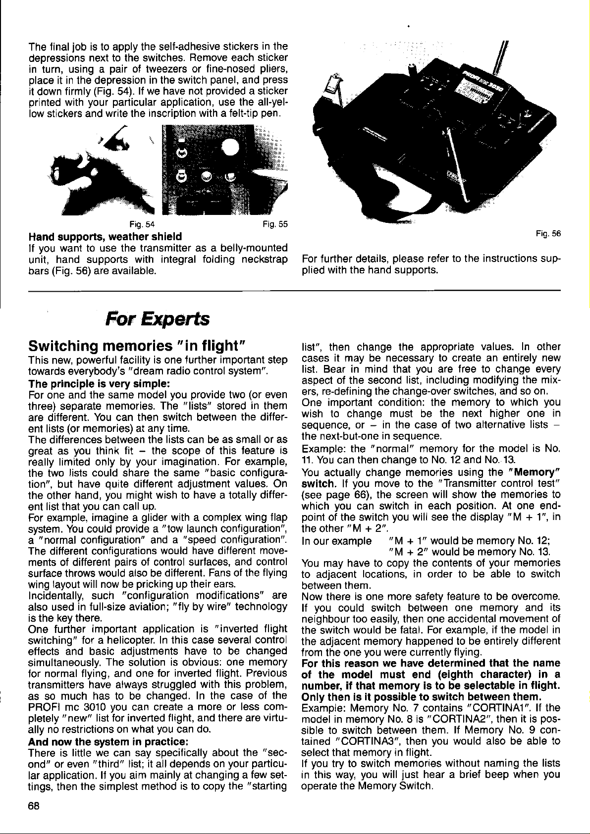
job
final
The
deoressions
in turn, using a
place
it in the depression
it
down
printed
low stickers and
is to apply the self-adhesive
next to the switches.
(Fig.
firmly
your particular
with
pair
of tweezers or
lf we have not
54).
wnte
the
stickers in the
Remove
fine-nosed
in the switch
application, use the all-yel-
inscription with a felttip
panel,
provided
each
and
a sticker
sticker
pliers,
press
pen.
Fig.54
Hand supports,
you
lf
unit,
bars
want to use the transmitter as a belly-mounted
hand supports
(Fig.
56) are
Switching
This new,
towards everybody's
The
For one and
three)
are different.
lists
ent
The
great
really
the two
tion", but
the other
list that
ent
For example,
system.
"normal
a
The different configurations
ments
surface
wing
Incidentally, such
also used
is the
One
switching"
eflects
simultaneously.
normal flying, and one
for
transmitters
as so
PROFI
pletely
ally
And now the system
There is
ond"
lar application.
tings, then
powerful
principle
separate
(or
differences
you
as
limited only by
lists could share the same
have
hand,
You could
of different
throws
layout will now be
in full-size aviation;
key
there.
further
and basic adjustments
much has to be changed.
mc 3010
"new"
no restrictions on
little we
or even
weather shield
with integral folding neckstrap
available.
fur
$rperts
memories
facility is one turther important step
"dream
is very simple:
the same model
memories. The
You can then switch between
memories)
between the
think
qurte
you
you
can call up.
imagine a
configuration" and
would
important application is
for a
The
have
list tor inverted
"third"
lf
the
simplest
at
fit
your
diflerent adjustment
might wish to have a totally differ-
provide
pairs
also be
pricking
"configuration
helicopter. In this case several control
solution
always
you
can create
what
in
say specifically about
can
list; it all depends on
you
aim
radio control system".
you
any time.
lists
-
the scope
imagination. For example,
glider
with
"tow
a
would have different
of
control
difterent. Fans of the
is obvious: one
for inverted tlight.
struggled
flight, and there are
you
practice:
mainly
method
Frg.55
"in
flight"
provide
"lists"
can be
launch configuration",
"speed
a
up their ears.
"f
ly
have to be changed
can
at changing
is
stored
of this teature is
"basic
a complex
surtaces, and control
modifications" are
wire" technology
by
"inverted
with
In the case of
a more or less com-
do.
to copy
(or
two
as small or as
values. On
configuration".
this
your particuthe
even
in
them
the differ-
configura-
wing f lap
move-
flying
flight
memory
Previous
problem,
virtu-
"sec-
the
a few set-
"starting
For further details,
plied
with the hand supports.
list", then change the appropriate
cases
list. Bear in mind that
aspect
ers,
One
wish to change
seouence.
the next-but-one
Example:
11. You
You actually change
switch.
(see
which
point
the other
In our example
You may have to copy
to adjacent
between
Now there
lf
neighbour too easily, then one accidental
the switch
the adjacent
from the one
For this reason
of
number,
the
Only
Example: Memory
model in memory
sible
tained
select
lf
in this
operate the Memory Switch.
it may be necessary to create an
of the second list,
re-defining the change-over switches, and so
important
or - in the case o1 two alternative
the
then change to No. 12 and
can
you
lf
page
66), the screen
you
can switch
of the switch
"M
them.
is
you
could switch between
would be fatal. For examole,
the model must end
il
that
then is
to switch between them.
"CORTINA3",
that memory in
you
try to switch memories
you
way,
please
condition:
must
in
seouence.
"normal"
move
you
+ 2".
"M
locations, in order to be able to switch
more
one
memory happened to be entirely different
you
were
we have
memory is to be selectable
possible
it
No. 7
No.8 is
will
refer to the instructions sup-
you
are
including modifying the mix-
the memory to
the next higher one in
be
memory
memories using the
to
+ 1" would be memory
then
flight.
just
"Transmitter
the
will
in each
will
see
the
contents
safety
currently
determined
(eighth
to
switch
contains
"CORT|NA2",
you
without naming the lists
hear a brief beep
Fig.56
values. In other
entirely new
free
to change
for
show
position.
the display
feature to be overcome.
one memory and
flying.
between them.
"CORT|NA1".
lf Memory No.9 con-
would also be able to
model is No.
the
No. 13.
control test"
the memories to
At
your
of
movemenl of
if
the
that the name
character) in a
then it is
every
on.
which
"Memory"
"M
when
you
-
lists
one end-
in
+ 1",
No. 12;
memories
its
model in
in flight.
lf the
pos-
you
68
Page 71

Three
1. In
"CORT-T11"
instead of
"CORT|NA3".
turther tips on
the example
instead ol
"CORTINA2"
In this case
NF for normal
names
purpose.
not
2. lI
the keypad,
the
pen: you
will then remind
inal numbers
The f
very inlormative
you
change
please
"basic"
position.
want to change
this subiect.
above
you
"CORTINAI',
and
flight, and
you
on their own.
memories
check
that the
Otherwise
to, say, Memory
the names
could
use
"CORT-NF2"
"CORT-HS3"
TL
stands
HS for
of which
for tow
high speed.
list serves
must remain; but
in the
"normal"
Memory Switch
following
the
No. 13.
instead of
launch,
The
which
they are
trom
way
is in
will hap-
Let's
suppose
set up as
in the
changes
end uo at
that it contains
"switchable"
a
wrong
to the
position,
new
No. 14 or
able confusion.
Please don't
3.
tasks; it always
example,
berchanging
as easy
Control
to use the
options,
up another
use this
"costs"
you
could execute
f lap by switching
memory.
model list which
a
lf the Memory
one.
transmitter
the
memory, and instead
No. 15. This can
Jeature tor
you
one or two
lead to consider-
"simple"
a simple change
"Fixed
and this alternative
memories; but
Value"
from the
would
you
have
Switch
immediately
you
of No.
13
switching
memories.
For
of cam-
just
it is
Transmitter
not
swallow
is
Servo
with
On
process
turing separately
ailerons.
For
which act
of
feature differential
longer be
Exahple:
In such
sequential
An example
assignment
more than
page
26 we discussed
for the aileron
controlled,
The recommended
=
Servo
Servo
No. 1
No. 5
wings
used.
"Quadro-flap"
cases
which have
Aileron 1
=
Aileron
(mixed)
as
movements, this assignment
the servos
pairs".
will make this
for wings
two controlsurfaces.
"traditional"
the
servos
of models
electronically
assignment
2
more than 2 control
ailerons,
arrangement
and all
(see
must be
clear:
assigning
with wings
fea-
differentiated
is as follows:
can
91).
all
to
no
"in
surfaces,
of which are
page
assigned
In the drawing
3 control surfaces
ailerons,
have already explained
We
(with
vos
cussed
ootion. Now all
vos at the assignment
In our example,
like this:
out
Servo
Servo
Servo
Servo
Servo
Servo
No. 1 controls QUADRO
No. 2
No. 3 controls QUADRO
No. 4 controls
No. 5 controls QUADRO
No. 6 controls
This should
you
per
stop at
do
servos
simply
lf
movement
we show an
per
wing, all of which
and all
selecting
of which
"QUADRO"
the
and adiusting
that remains
stage.
assigning
controls QUADRO I
OUADRO J
QUADRO I
make everything
panel, (normal
wing
No. 4.
not keep to this sequence,
will not be correct.
"extreme"
wing
layout, with
are to work as
require diflerential
you
how
control the six ser-
mixer); we
the
is the order
"
in sequential
Outboard
I
of control
Centre
I
movemenl.
have
"Differential"
of the six ser-
pairs"
pair
surfaces
pair
of control surfaces
Inboard
I
of control
lf
clear.
Quadro
pair
surfaces
you
have only
arrangement),
differential
also
works
aileron
dis-
two
The
We have already
36,
"
noticed already
assigning
What
"Sl"
switch),
input
has an
position"
lf,
if the slider
(OFF).
side
point
end-point
case
"Sl"
in connection
Fixed
is
is
another
"l".
for example,
lf
of
again,
the other
switch
Value 1" and
that
the switches
"Sl"?
"non-hardware"
in this case
Firstly,
"idle
at both
you
"Sl"
of the slider
"Sl"
position"
end-Points.
you
is set
move the slider
switches
"Sl"
"side"
mentioned the
with the transmitter
"Fixed
"Sl"
is offered in the
51 - 52.
coupled
"three-position
is
a
in the centre,
connect
to centre, then
on. lf the slider
switches off
the same
"Sl"
of
"Sl"
Value 2".
switch,
to the transmitter
a slider
to one end-point,
immediately.
is switched
control to
"Sl"
applies;
Fig.57
page
switch
control
and a
leaves
on
options
You may have
menus
(i.e.
switch",
is
on and off.
when
a software
control
i.e. it
"working
"1",
and
at
also
one
then
the end-
At the other
in this
only
idle
"Sl"
ln this case
ooint switches
imagination
functions.
ing
main application
The
has the same
were
you
can use
ever.
In this
case a
nected to
(short
toggle)
"hardware"
It this
in this application)
the
ates
is a 3-position
effect
with the switches
used
compare
tions;
change-over
And that
dif{erent
"real
input
"1";
or Order
switch
"software"
is operated,
this with 51 - 55,
switches.
is exactly
"
Fixed
what we
Values" !
effect as
fitted to
the slider.
this feature
"Sl"
of
hardware"
for
No. 7 5700
switch
change-over
51 - 55;
is rather simpler,
3-stage switch
example
(long
(actually
a transmitter control
then of course
"Sl"
switch,
but which
which are
need to switch between
if two end-
With a little
for many
Order
No.7 5699
toggle).
well. The
as
which can
has 3
only simple
interest-
how-
is con-
it oper-
final
be
posF
2
Aq
Page 72

"Sl"
main application of
The
transmitter control options
the
A further example
ber-changing
We will assume that transmitter control
to the
OPTIONS"
FLAP".
Press the N key, and
ootion.
Press the
El
"FLAP"
menu, and from there to
key
!
key, and then leaf through to
rE:
will make eveMhing clear:
flaps with 2 switchable
function. Move to the
("switch
FLHF F I ii- 1I
is in
conjunctlon
"FlX-1"
positions".
E is assigned
"CONTROL
leaf
through
corner"), switch ON with the
"1":
to the
L I +. lt:tttllr
pressing
After
Fixed
While
tion.
that
so
itself!
servo
the Z key
Value; for
you
example,
you
are setting this up, operate the switch
can see the results of
you
"tow-launch"
the
now set the first
can
your
with
"
FIX-2'.
and
efforts at
"cam-
"CONTROL
E:
"FlX-l"
posi-
flap
the
Now to the second
Press the N key again, leaf through
"Flx-2"
the
You will see this display:
oprion.
rE:FLI]F
t:ttllt/
Press the Z key and
position (e.9.
during the adjustment
so that
Once
flaps can be controlled in the
Switch at centre:
The Jlap servo
Switch at the end-points:
The flao servo
Dositions.
you
can see the effect directly.
you
have finished the
Fixed Value:
FIii-i!
: rll.;;^r
5I
you
can adjust
speed).
is
runs
Here
again,
procedure (opposite
setting
lollowing way:
controlled by the slider.
to one or
other of the
operate the switch
with the
up
El
the other flap
end-point),
process,
ore-selected
key to
the
Transferring
programs
between two transmitters
you
Let's imagine that
list lor
a
leagues buys a kit of the same
sesses
your
program
dealer,
mitter a suitable
you.
Programs
direction between
As
need
You
Transfening data between lwo transmitters
as copying
tion
memory, which
For IMPORT that
For
We will assume that
the current
12, then
be overwritten,
in that transmitter.
For this reason
in any doubt,
memory.
First
Connect the two
inserting the
both transmitters
your
model
a PROFI mc 3010,
hard work with him by transferring a copy of
to his transmitter. You may even
as a special service,
(model
you
will
see,
is
the transfer
transter in either direction:
can
From
("
From
for a transfer is therefore always the current
EXPORT this means that
IMPORT.
your
Export").
another
from one memory to another.
you
memory. lf
memory 05 in the destination transmitter
regardless of which memory
you
rather than risk overwriting a colleague's
transmitters with the transfer lead, by
plugs
have worked hard
"XYZ",
list for
lists)
two PROFI mc 3010 transmitters.
this is a very simple matter.
lead,
transmitter
transmitter to
have selected
is
exactly
you
you
should always
in the two charge sockets. Switch
on.
On
and then one of
model. lf he
you
can share the
will
copy
helicopter he has
the
can be
Order
have
the transmitter which
transferred in either
No. I 5120.
to
another
yours ("lmport").
in
what is required.
you
selected
now EXPORT from memory
IMPORT if
at
find
into
is the
The
your
transmitter.
must take care.
memory 05 as
perfecting
your
col-
pos-
also
fruits of
your
your
that
your
trans-
just
sold
you
All
transmitter
same
destina-
will
is
current
you
are
is
to
IMPORT select the target or destination
current
Move to the COPY
Release
the
The display
Now
the second
do this
number using E or
09. The display should
Press the
place
lf
Jind
source transmitter.
lf for any reason the transter does
laulty cable, cable
not switched on),
sage
the transfer
EXPORT.
This is
explanation.
First move to the
the
the destination of the data transfer.
memory) using the
MODE with
key until
El
you
reach the
will look like
rt']ütiE
rFF:f'l
you
have to inform
transmitter from which it
press
r[,][t[:'E
rFF:t'l,
E)
in a fraction of a second after
you
now
take a
it
that
contains
"MODE:-Error-".
again.
a similar
memory which, in the second transmitter,
.
and select the desired source
N
E.
key and
look
the same data as memory 09
not
your
operation, so
"SHIFT
SHIFT
MEMORY menu with
the
Z
this:
!
rirt !
t:l'-1 :
Ei:TEE:H
your
In our example this
now look like this:
:
EiiTEFjH
you
are done.
your
at
plugged
transmitter will show the
Put the
MEMORY"
MEMORY
key
and
IMPORT mode.
I t'lFrlE:T
transmitter the
is
It'lFt:tFjT
The transfer takes
you press
current memory
not take
in, source transmitter
problem
we
can cut down
memory
leaf through with
fetch
to
right
menu
(=
menu.
To
will
in
the
mes-
try
the
to be
.
EIS)Z
memory in
data.
memory
is memory
the key.
you
place (e.9.
and
and select
is
70
Page 73

Move
"
the
The display
number
to the
MODE:EXPORT".
key.
Sl
06
"COPY
should
Jlashing:
rf'lü['E
rFFlt''1.
MEMORY"
Activate the source
look like this,
:
E:":FüFtT
menu, then
memory
with the memory
ut: FiEITH
to
using
Two further
you
1. ll
copy or delete
switch
memories
2. To ensure
versions
with memories 1 to
ble
points:
should
the transmitter
will then be unchanged.
that import/export
of the transmitter,
wish to interrupt an
process
off briefly.
15 and
you
atter
The data
is
this f unction
Mx.
import, export,
have started, simply
in
possible
is only
model
the
between all
possi-
the
Press
The
FIXED
virtual
you
wish to operate a
lf
switch),
for the
two fixed servo
are
Assign
Move to the
Select
assign
When
FIXED
Set up
Move to the
with the sequence
menu
ll. Tho
Connecting
receiver
The
Servos,
MULTINAUT-p|uS
directly
receiver battery
The
"switch
key, and the data
@
VALUE
"transmitter
you
do not
purpose.
first:
the servo
it to the
you
assign
VALUE
as tollows:
ADJUST / SERVO
need to
Assuming, that
positions.
ASSIGN/SERVO
you
FIXED VALUE
the
will not
reeeiYing
servos
is the
motor
to it.
harness"
controllers,
receiver
(Fig.
will
be
control"
servo with a stick
"lose"
wish to use,
"genuine"
appear.
@ Z Z,
"heart"
is connected
60).
a transmttter
is, that all
menu
press
"transmitter
transmitter control,
/ TRAVEL
and
and
batteries
the receiving
of
switch
modules
to the
transferred.
(or
function
a
control
you
need
with
@Z[!N.
the Z key, and
control".
+ REVERSE
select the
servo
s1stem
system.
modules and
are connected
receiver via a
you
which
press
position.
In the
determine
vatue.
The servo
determined
be able
level with the
with ! . Now
end-point,
position
ond
For reasons
smaller
be connected
can
marked,
connected directly,
number;
What
an expansion
of a
sists
to the
two sockets
the
have assrgned
set the servo
and
S,
"SWITCH
which switch
position
in the menu ADJUST/SERVO/CENTRE.
to do this,
press
receivers are combined,
for example,
in this case channel
you
if
need both
plug
receiver socket;
SERVO"
for the second
you
key, and activate
m
move the
the
for the
of space, certain
servo.
to one socket.
adapter
and two sockets.
on the adapter
FIXED VALUE.
to
position
menu
is associated
first
must
physical
key, and set the desired
Z
"8/9".
and
functions?
(Order
the two servos
Only one
this is always
8.
No.8 5060),
for the first switch
you
now
with the fixed
switch
go
back by one
Centre adjustment
switch to the
output sockets
that two servos
so
This type
In this case
plug
The
(Fig.
61).
ol
servo can be
which con'
is connected
are connected
Finally
have to
position
To
menu
other
sec-
on the
socket
lower
the
you
need
to
is
is
The receiver
l to a
servos
corresoonds
servo output
maximum
which can
to
sockets are
oJ 10, depending
be connected.
one control
function.
numbered
on the
Each servo
number of
Fis.60
from
output
Fig.61
71
Page 74
The switch
is
This
in the harness
rated
syslem
the model's
Switch
please
details.
socket
harness supplied
charge socket
means
to open up the
ing
harness
plugged
on and
harnesses
refer to the
Some
for charging
that the battery
into socket
otf. The switch
fuselage side.
versions are
is integral
"
8". The switch
is used to
are available
main MULTIPLEX
the receiver battery.
with the set
can be recharged
model
turn the whole
itself can be
in several
fitted with a separate
(Order
with the switch casing.
(Fig.
62).
incorpo-
receiving
installed
forms;
catalogue
On the switch
No. I 5100)
This
without
hav-
in
for
the
Fig.62
PPM or
PCM
of the
information
the
receiver is able
ues lo send
it again
Safe).
On the
lead to the PCM
much later than
PPM
tage if
model, because
transmitter
Which types
can
PCM
MULTIPLEX
All
new transmitter.
PPM
when set
or I channels
means that
This
receivers
decode
Fail-Safg
Only
After about
servo
vos are
of the
ture
it can
Single-superhet
you
lf
VHF radio
MHz), conventional
perhet)
ence.
duces
perhet
different
gether
PCM?
(Pulse
two transmission
receives a signal
Thus PCM eliminates
other hand, this
(Pulse
you
require ultrajast control
at a
Modulation)
Code
methods.
is
encoded
to recognise
the last
Position Modulation) still
"good"
from the transmitter
interference suppression
pilot
failing to
with a PPM system.
information is broadcast
the
faster rate than bv a
receiver
of
be used?
PCM receivers can
to PPM, the transmitter
(see page
you
(and
all FM
least 7 channels)
at
("emergency
available
runs to the
automatically
work.
with PCM-DS
0.8 seconds
receiver, and
250lo
13 for method
use all
can
PPM receivers
of interference
Dosition,
reset to centre.
must be switched on
or double-superhet?
your
operate
transmitter
in the
In technical terms:
adjacent-channel
receiver. The double-superhet
technology
model
35 MHz band can
which eliminates the
in the vicinity of a
(frequency
radio control systems
the
interlerence
is
the
In the case of
by the transmitter.
interference, and contin-
signals to the servos
jittering.
servo
notice interference until
response
PCM transmitter.
broadcasts
MULTIPLEX
with this transmitter.
position"
receivers!
and all
suffer
powerful
"intelligent"
more
PCM
until
(see
has the advan-
your
from
by the
your
be used
lor
Fail-sate
range
to the single-su-
receiver utilises
with
either
of switching).
FM PPM
which can
servos)
the throttle
the other ser-
is a fea-
before
powerful
103 to
(single-su-
from interfer-
transmitter
problem
alto-
The
Fail
can
7
105
pro-
Arrangement
of battery,
receiver
The diagram below
arrangement
model. We
your
system
vou start construction.
The
When installing the
observe
receiver
a
Keep the
motors and electric
.
Lead the receiver aerial
shortest
o
Protect the receiver
foam rubber and stowing
.
Never alter
.
Deploy the receiver aerial
possible.
a
your
lf
ments, do not deploy
fuselage
.
Do not stick the
model
screenrng).
Range
Range testing
safety
have cooked
levels when
of the
recommend that
is to be installed
following
the
receiver
possible
the length of
Never leave it coiled up
model
(signal
which is reinlorced
testing
can make a significant
up a standard
RC
Servo Switch
receiver
points:
well
ignition systems.
route.
from vibration by
incorporates carbon
screening)
receiver aerial
you
servos
shows
away
the receiver aerial
are
the most
system
out o{ the
it
the receiver aerial.
operating
components
you
decide
in the new
in the model,
trom
loosely in the model.
in as straight
to any
with carbon
recipe
model
Receiver
powerf
model by the
wrapping
in the
f ibre reinforce-
part
fibre
improvement to
your
for range testing
and
favourable
in the
exactly
ul electric
a line as
model.
inside the
model.
how
before
Fig.63
please
it in
of the
(signal
We
72
Page 75
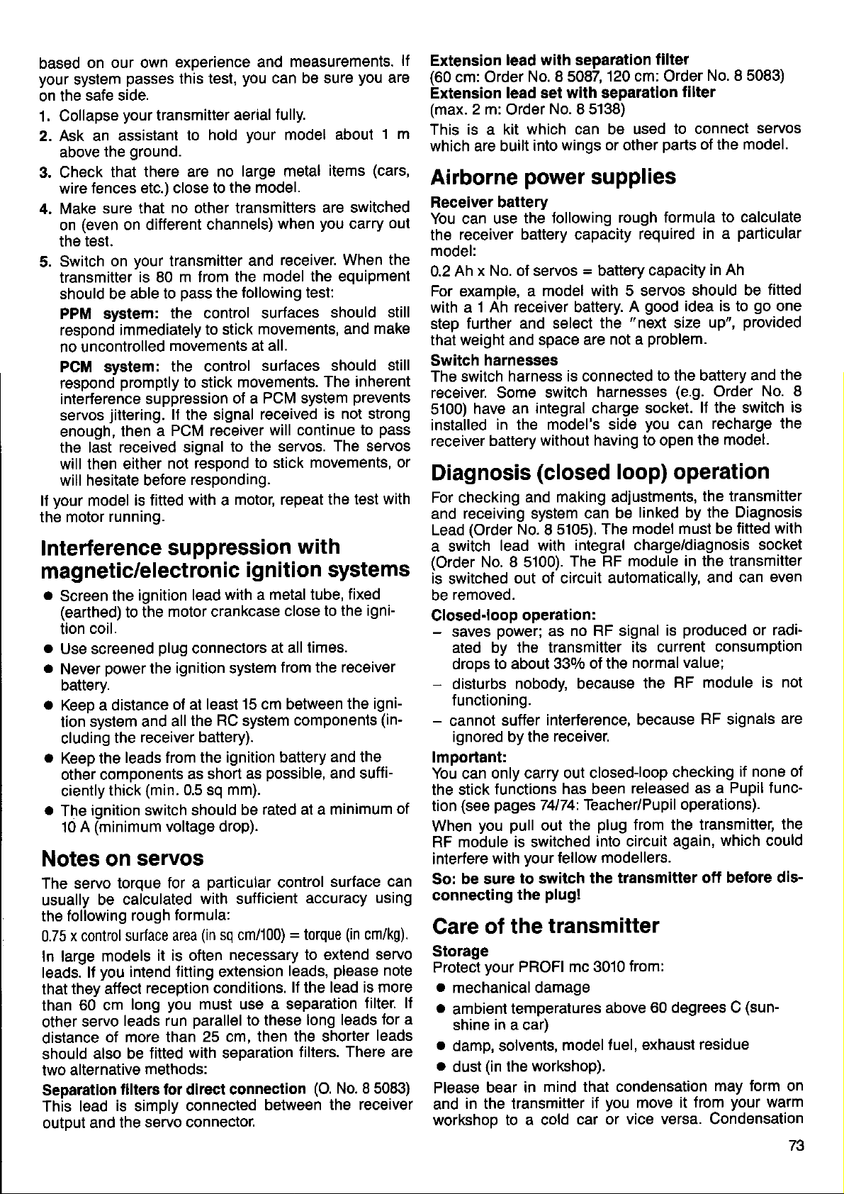
based
your
on the
1.
2. Ask an assistant
3. Check
4, Make
5.
ll
the motor
Interference
on our own experience
system
Collapse
above
wire
(even
on
the
Switch
transmitter
should be able
PPM system:
respond immediately
no uncontrolled
PCM system:
respond
interference suppression
servos
enough,
the last
will then either
will hesitate before
your
passes
safe side.
your
ground.
the
that
fences etc.) close to
sure that
on different
test.
your
on
promptly
jittering.
then a
received signal
model
is fitted with a
running.
this test,
transmitter
hold
to
there are no
no other transmitters
channels)
transmitter
is
m trom the
80
pass
to
the control surfaces
to stick
movements at all.
the control
to stick
lf
the signal
PCM receiver
not respond
responding.
suppression
magnetic/electronic
.
Screen
(earthed)
tion coil.
a
Use screened
a
Never
battery.
a
Keep a distance
tion system
cluding
.
Keep the
other components
ciently
.
ignition switch should
The
(minimum
A
10
Notes on
The servo
usually
the following
x control surface
0.75
In large
leads.
that they
than
other
distance
should
two
Separation
This
outDut
lf
60 cm
servo
also be
alternative
lead
and the
ignition lead
the
to the
power
the
leads from the
thick
motor crankcase
plug
connectors
the ignition system
of at least
and all
receiver battery).
(min.
the
short as
as
0.5 sq
voltage drop).
servos
torque for a
calculated
be
rough
models
you
affect
of more than
it is often
intend titting extension
reception conditions.
long
leads run
fitted
methods:
tilters for direct connection
is
simply
servo connector.
particular
with sufficient
formula:
(in
area
you
musl use
parallel
25 cm, then
with
connected
and
you
aerial
your
large metal
the model.
and
model the equipment
following test:
the
movements, and
surfaces should
movements.
PCM system
of a
received
will continue
to the servos.
to stick movements,
motor, repeat the
ignition systems
with a metal tube,
15 cm between
RC
system
ignition battery
possible,
mm).
rated at a minimum
be
sq cm/100) = torque
necessary to extend
to these
separation
between
measurements.
can be sure
lully.
model
when
receiver. When the
you
about
items
are switched
you
should
The inherent
is not strong
The servos
1 m
(cars,
carry
make
prevents
pass
to
test with
with
fixed
close to
at all
from
components
control
leads,
ll
a separation
the shorter
the igni-
times.
the receiver
the igni-
(in-
and the
and suffi-
surface
accuracy
lead is more
the
long leads
filters. There are
(O.
the receiver
using
(in
cm/kg).
servo
please
No. I5083)
note
filter. lf
for a
leads
lf
Extension
(60
are
cm: Order
Extension
(max.
This is a kit
which are built
Airborne
Receiver battery
You can use
out
the
model:
0.2 Ah
For example, a
with a
still
step
that weight and
Switch
still
The switch
receiver. Some
5100)
installed
receiver battery
or
Diagnosis
For checking
and
Lead
a switch
(Order
is
switched
removed.
be
Closed-loop
-
saves
ated by
droDs
-
disturbs
functioning.
-
cannot
ignored by the
lmportant:
You can
the stick
tion
of
When
RF
interfere
can
So: be sure
connecting
Care
Storage
Protect
.
mechanical damage
.
ambient
shine in a car)
a
damp, solvents,
.
dust
Please
and
workshoo to a cold
lead with separation
No. I5082
lead set with separation
2 m:
Order
No.
which can be used
wings or other
into
power
the lollowing
receiver battery capacity
x No. of servos = battery
model with 5 servos
1 Ah receiver battery.
further and select
space are
harnesses
harness is connected
switch
have an
integral charge socket.
in the model's side
without having to open
(closed
and making adjustments,
receiving system can
(Order
(see
module is switched
in the transmitter
No.
I5105).
lead with
No. 8 5100).
out of circuit
operation:
power;
to about 330/o
suffer
only carry out closedloop
functions
pages
you pull
with
of the
your
(in
the workshop).
bear in
as
the transmitter
nobody, because
interference, because
receiver.
has been
74174:
out
your
fellow modellers.
to
switch
plug!
the
transmitter
PROFI mc 3010
temperatures
model
mind that condensation
120 cm: Order
I5138)
supplies
rough tormula
A
"next
the
not a
harnesses
loop) operation
be
model must be
The
integral charge/diagnosis
The RF
no RF signal
Teacher/Pupil
the
car or
module in the transmitter
automatically,
its current
of the
the
normal value;
released as a
plug
from the transmitter,
into circuit
transmitter off
from:
above
fuel, exhaust
you
il
move it
vice versa. Condensation
filter
No. I5083)
filter
to connect
parts
of the model.
required
capacity
good
problem.
to the battery and
you
linked by the Diagnosis
the
60 degrees C
in a
in Ah
should be
idea is to
size up",
(e.9.
Order
lJ the switch
recharge the
can
the model.
the transmitter
and can
produced
is
RF module
RF signals
checking
operations).
again,
residue
may form on
from
servos
to calculate
particular
fitted
go
one
provided
the
No.8
is
fitted with
socket
even
or radi-
consumption
is not
are
if none of
Pupil func-
the
which could
before dis-
(sun-
your
warm
73
Page 76

prevent
may
are not sure,
transmitter
transmitter
Cleaning
great
Take
ter when
Do not use any
the transmitter
adeauate.
Dust is best
Maintenance
Your PROFI
which
essential
working tunctions
the transmitter
carry out a careful
warm up or cool
should be
the transmitter
care that
you
reouire maintenance. Nevertheless
safety
cleaning the case.
are
abrasive or solvent-based
case. A
removed with a soft
mc
3010
measure to
periodically.
completely dry
no liquids
mild household cleaner
working
range test, and
down thoroughly.
get
paintbrush.
transmitter contains
check
The transmitter battery
Please
their
cycres.
.
a
.
note that new battery
full capacity until after about
rapid-charge
Charge
have
times at
ing them.
Do
that
Charge up batteries
perature
new,
not
been used
the normal
not rapid-charge a battery unless
it was designed
is in the range 0
(slow)
for it.
for a long time) at
only when the ambient
packs
batteries
rate
to 40 degrees C.
properly.
inside.
inside the
cleaner on
radio range and all
not achieve
do
10 charge/discharge
packs
(or
least three
before
rapid- charg-
you
you
lf
let lhe
The
transmit-
quite
is
parts
no
it is an
which
cerlain
tem-
o
Avoid
.
.
Storing batteries
you
11
take special
State
Experience shows that
discharged
Self-discharge
NC
unfavourable
age they are
Maintenance charging
The transmitter battery can be
for use at any time, by
70 mA. The MULTIPLEX Combi-Charger
5540 includes a
For
Teleohone Service
day
lowing number: 01049
placing
on the cells themselves.
and
Replace old batteries
packs
NC
waste, and must be disposed
chuck
them
not use
do
of charge
packs
lose about 10lo of their charge
mechanical
fall into the category
in the rubbish bin!
your
note of the following
(empty)
generally
state.
conditions,
70 mA output.
MULTIPLEX
questions
to Thursday between
regarding the transmitter and
is available.
-7233-7390.
stress on the
good
in
transmitter
NC
i.e.
completely
charging it constantly at about
time.
of
points:
packs
should be stored
after
kept topped up, ready
Hot-Line
You
2.00 and 4.00
properly.
three months' stor-
flat.
power
of dangerous
for a long
per
Order No.
can call
pm
leads
Don't
period,
under
day
its
use
us Mon-
on the
just
in a
14
our
fol-
Types of servo
The right servo
Servos
They
operate
mechanisms.
round" servo
ally
Principal differences
Type ot output
Most servos
put
degrees.
undercarriages
move through
lation a
The
to alter
lever, as is the case
Power
Servo
and
requires a
more current) or a
slows
lf speed
carriage
In large,
own.
soeed.
you
larger than
are
move the control surtaces
throttle arms and
ofter the best
arm rotates, usually
For special
linear-output servo
fundamental disadvantage
servo travel by
(torque)
power
the reduction
down
is unimportant - e.g.
-
heavy models our
They offer outstanding
lf several
should always select
lor
every
the muscles of
For most
quite good
is
price : performance
in servos:
are of the
-
+/- 90 degrees.
is
determined
more
its response).
the slow
normal capacity.
"rotary-output"
purposes
there are
fitting a longer or shorter
with rotary servos.
ratio of the
powerful
higher
Power Servo is the best solution.
Profi
application
your
radio
control
and steering
brakes, switches and
purposes
enough.
through an angle
high-power servos
offers distinct advantages.
by the
gearbox.
motor
gear
for a retractable under-
Profi
power
servos
a receiver battery
high-quality
a
These servos usu-
ratio.
-
e.g. for retractable
In some types of
is that
Servos
it is not
power
(which
reduction
combined
are used
linkages,
The out-
type.
ol +l-
possible
the motor
ol
Greater
consumes
ratio
come into their
with high
in a model,
system.
release
"all-
45
which
instaF
output
power
(which
with a
Speed
Servo
ratios.
expense
servos
speed
Resolution
This is where the orecision
Our
Dimensions
For
by far the
size, combined
we
The mc
(or:
Our
and orovide characteristics
possible
For example:
The servos
mc, Power-mc
many an unusual
speed, as
A low reduction ratio
power.
oJ
quite
are
models
(accuracy)
top models achieve
purposes
some
most important
recommend our Pico Servo.
servo
the computer
mc servos are
with
in this family
in
a car,
For
fast
require
and weight
specialised
-
especially
plenty
with
family
your
in
controlled by a
conventional
.
higher continuous
.
smaller deadband
.wider
o
and Jumbo-mc - are
operating
programmability
intractable
and
is a tunction of
gives
most applications our standard
enough.
of a servo
a resolution
requirement is minimum
power.
of
servo)
which have never been
technology.
-
Micro-mc, Royal-mc, Profi-
gearbox
high speed, at the
Only extremely
Speed Servos.
manifests itself.
figure ol O.2o/o.
wing installation
for
For such cases
micro-processor
performance
voltage range
capable of solving
problem.
high-
-
74
Page 77

Sp_ecialist-terms
fixed-wing
tci
ref,erri ng
aircraft
Spoilers:
A'vague
which
wing
brakes
tlected
term used
primarily produces
lift). For example: airbrakes,
camber-changing
or
more than 30 degrees
for any
part
drag
the control system
of
(and
sometimes aftects
rotating trailing
which
flaps
negative
or
be de-
can
positive.
edge
Dividing the
the functions
up
more efficiently
long-span
aileron
In the
movement
greater
hand, the llap
should
ensure docile
Aibron Carn!,or
flaperon into two
ol aileron and camber-changing
in aerodynamic
wings
(better
response).
interests of
good
of the outboard
than that of the
movement oJ the
greater
be
than that of the
stall behaviour.
makes it
terms,
possible
particularly
lift distribution and
aileron
response,
the aileron
control surface
inboard surface;
on the other
inboard control surface
outboard surface,
-
Carnber
-
charu|.ng
cttarying
naB
lbB
to set
tlap
on
improved
should be
to
camber-changing
Control
surfaces
vary the camber
characteristics
requirements.
increase
an
a slight
around
lf flaps
rises considerably.
drag
(spoilers,
aid
in the wing's
increase in drag. Small
2 - 3 degrees,
are deflected
flaps
at the trailing
of the
of the
Positive def lections
crow system).
Flaperons:
Fuli-span
which
Delta
Full-length
models
elevons
control surtaces
double as
ailerons and
("elevons"):
control
surfaces at
without a tailplane
double
as ailerons
(or
simply
flaps)
edge of the
wing, used to
wing section, and thus
wing, to suit
lift
coeflicient
particular
(flaps
(slow
down)
negative deflec-
reduce drag
more than about
Flaps
at the
for high-speed
+30 degrees,
make a usetul
wing trailing edge,
camber-changing
Cambr-
cha.qang nap
the wing trailing
(delta,
flying wing).
and elevators.
Fis 65
also the
Jlight
produce
flight), with
tions,
llight.
landing
flaps.
Fig.66
edge, on
The
crow system
An
extension
the mixed control
control surfaces
(flap
down),
position
(F3B
class)
(aileron
the
of
surlaces as
are set to a
the outboard surfaces
(flap
up). Used on
which are
sooilers.
Oandr€r
Snap-flaps:
Mixed
Often used
of the
changing
increase
accompanied
reduced.
of
"square"
function: elevator
on aerobatic
elevator.
lf up-elevator
flaps are deflected
in the wing's
by up{lap,
The overall effect
very tight
looping manoeuvres
figures.
brakes)
"Quadro"
positive
high-performance
not Jitted with
-
a*Lnging
p
lt
-
camber-changing
models
is applied,
lift coefficient.
and the
is that the aircraft
Fis 68
mixed function, utilising
"spoilers".
to a negative
The inboard
braking
position
braking
gliders
proper
spolbr
Apoibr
to reinforce
airbrakes or
Fig.69
flaps.
the effect
the camber-
down; the
wing's
result is an
Down-elevator
litt
coefficient
is
is
is capable
-
ideal for the
euadro:
Full-length
separate
as aileron
control
flaps
and
surfaces
per
wing.
camber-changing
(flaperons)
Each control surface
tlap.
divided
Fis 6/
into two
doubles
"
(or
V-tail
buttertly
Combined elevator
When elevator
the same
in opposite
direction.
directions.
tail')
and
is applied,
When rudder
rudder in the
both control
surfaces
is applied, they
form of a
move in
Fig. 70
"V".
move
TC
Page 78

Diffierential:
Term used
compensate
known
lf ailerons
aileron
moment
to the
is then
This makes
lor unequal
for the
as adverse
move an
the outside of
on
in the opposite direction
increase
required
for ditficult control
aileron
"
negative"
yaw.
equal amount
in
to
an increased
drag;
counler
movements,
roll effect,
up and down,
the turn
the
produces
to that
rudder
yaw.
characteristics
intended to
otherwise
the
yawing
a
oJ the turn, due
movement
loss
and a
ot efficiency,
model
Unequal
than do!\,n) can
it altogether.
The effect
depending
For
this
As a
tests.
ulmovement,
which can be
gliders.
aileron
of adverse
on the aircraft's
reason it
good
and 500/o-700lo
mo/emenb
is
always
starting
this effect
yaw
reduce
very noticeable
(much
varies
geometry
necessary
point
down-movement.
more up movement
greatly,
or even eliminate
from model to
wing sections.
and
to carry out
we recommend
in large span
model,
practical
1000/o
Some
Swashplate:
This comoonent
ments from the
rotor blades.
Collective
Generally
tive".
Variation
same
It no change
force is coincident
Cyclic
Generally
A variation
course
olane
force
used
Ditch-axis control:
The resultant
back
ward). Corresponds
Jixed-wing
roll-axis control:
The
Corresponds
craft.
Tail rotor:
Produces
main
trol, corresponding
craft.
Gyro:
The
sends
control system.
main
gyro
Gyro suppression:
This system
the
movements around
Pitch^hrottle
ln
an
stant at
opening
Ditch
between
in the
derived
helicopter
mixes and transfers
fixed control
pitch
variation:
known as collective
in the
time, to control
pitch
known as
of one
of the
is no longer coincident
lor:
(when
resultant
a torce
rotor
gyro
appropriate
rotor results
important aid to the
is an
gyro,
so
ideal
all motor
and closing
is increased or decreased.
collective
form of a
from the
pitch
lift.
is made to cyclic
with the
variation:
in rotor blade
rotor blades
viewed from behind
aircraft.
lift force oJ the
to aileron
in
single-rotor
registers unwanted
reduces or entirely
that the
helicopter the
"cyclic
rotation. The effective
lift force of the
to up-
which counteracts
to
corrective
As
every
in a change
the
curve:
power
pitch
graph,
collective
terms
mechanisms to the
pitch,
angle
rudder control
the
of all
rotor
pitch",
pitch
is tilted, and the
with the
rotor is tilted
and down-elevator
rotor is tilted to
movement
helicopters.
signals
control command
in main rotor torque,
pilot.
pilot
can
yaw
axis.
rotor
speed
settings;
throttle whenever
and throttle
"curve";the
or
pitch
or simply
rotor blades at
pitch,
shaft.
or simply
which alters over
the model,
on a
Used
in a fixed-wing air-
yaw-movements,
suppresses
effect
would remain con-
this is achieved
can be considered
signal.
all control
the
result
rotor shaft.
fixed-wing air-
the torque
to the tail
last, intentional
The relationship
throttle
move-
rotating
"collec-
the
resultant
"cyclic".
the
is that the
resultant
lt is
forward or
looking
right or left.
for
involving
the effect
for-
on a
of the
yaw
con-
and
rotor
the
the
collective
signal
lift
lift
of
by
is
"3-Doint
Corner
and
"s-ooint
As above, but
corner
allows the
more accurately
istics.
Throttle
Throttle setting
conditions.
"Schlueter"
A seoarate servo
tor each
tions
oitch-axis
Characteristic
swashplate
axially; collective
controlled
oushrod
hollow
"Heim"
The Junctions collective
oitch
electronically
to two servos.
vos control
in the
"
uo/down" directions.
The oitch-axis
mechanically
Jrom collective
separate
controls
movement
Dlate.
Soecial
cal
Dossible.
curve":
points
maximum collective
points
rotor shaft
and roll are
flare compensation
for minimum collective,
pitch.
curve":
wilh two additional
mentioned above.
power
rotor
to the
pre-select (ldle-Up):
for rotor
control system
of the three
collective
and roll-axis.
feature: the
cannot
by means
located
control system:
"righVleft"
pitch-axis
feature:
inside the
and
These ser-
the swashplate
function is
de-coupled
pitch.
the
pitch-axis
of the swash-
mechanF
requirements to be
motor's
idle speed under
is used
func-
pitch,
move
pitch
is
of a
mixed
passed
and
A
servo
is
power
:
-\
hover collective
points
The s-point curve
between
output character-
"no{oad"
the
matched
Fig.71
76
Page 79

"CPM"
Abbreviation
nals for collective
tronically
servos
similar
imised.
control system
for
Collective
"composed"
and swashplate
mechanics, so
pitch, pitch-axis
(HEAD
and
there are
mechanical complexity
Mlx):
Pitch lvlixing. The control sig-
roll-axis are elec-
and
sent to the servos.
no mixer levers or
Between
is min-
Virtual swashplate
(or
lf a 3plate
swashplate
the rotor disc, as
locate
ti-blade
highest
rotated through
be
blade system,
can be
tual)
more) bladed rotor
intended for a 2-bladed system,
no longer corresponds
the mechanical
rotor at a
point.
mixed electronically to achieve
rotation ot the swashplate.
rotation:
it is not
linkage to each blade of a
point
90
lf
the swashplate
the
appropriate
pitch-axis
the
is mounted on a swash-
then the
to the
possible
degrees in advance
and
in design terms to
control system cannot
angle
roll-axis servo signals
an apparent
tilt of the
inclination of
to match the
mul-
of its
(vir-
Arrangrm€d
Frequency
crystals
frequency bands are available
Four
models in the U.K.:
The latter band
mc 3010
the first three bands.
The easiest
compare
of long
your
On
pressing
do that:
be changed.
swapped
A channel,
frequency band.
frequency
spot
station.
are diff
numbers.
and spot
transmitter and
them with the
(LW),
wave
radio
knob. With radio control
a
the transmitter
for a new one.
or spot frequency,
Instead ol
icult to
9d
bands, channels,
frequencies
l\llqz
27
35
40
459 MHz band
is used
way of
you
The receiver, on the other
corresponds
remember, we use standardised
band
MHz
band
MHz
band
very little
receiver are only available
imagining frequency bands
wavebands on
medium wave
can
has
Going back
the frequencies themselves,
the
for
(A
und B band)
present;
at
your
(MW),
probably
RF module
an
is a narrow section
to our
to one radio
and so
change
equipment
hand,
radio
transmitter, or
control
the
radio. Think
on.
bands by
we
which has to
analogy,
ot
PROFI
on
is to
can't
must
be
of one
which
channel
The crystals
frequency and the channel.
the
matched to each other
whv:
in the transmitter and
Always use
MULTIPLEX radio control
The
channel
the crystal.
=
transmitter)
Transmitter crystals
casing, and
number
next to it
"normal"
vellow one.
Caution:
Ordinary
cannol
receiver crystals
be used
ble-suoerhet
Double-superhets
a
special types
They are fitted
tals).
integral colourless
an
holder
tic
(Fig.
with extreme
genuine
is
you
or an
"E"
are enclosed
receiver crystals
with doureceivers.
require
(DS
crys-
with
plas-
66).
receiver determine
They must therefore
precision.
MULTIPLEX crystals
in
equipment!
always
printed
will see either
one face of
on
"S"
an
(Sender
(Empfaenger = receiver).
in a transparent
in a transparent
be
That is
your
blue
Fig. 66
77
 Loading...